Service Manual FORD Everest 2001-2007 [PDF]
2001 RANGER Repair Manual Supplement (F175-10-01I) CONTENTS Title General Information 2001 RANGER WL3 EVEREST W LT 3 R
101 0 54MB
Papiere empfehlen


![Service Manual FORD Everest 2001-2007 [PDF]](https://vdoc.tips/img/200x200/service-manual-ford-everest-2001-2007.jpg)
- Author / Uploaded
- โจ้ สแปร์แร็ค
Datei wird geladen, bitte warten...
Zitiervorschau
2001 RANGER Repair Manual Supplement (F175-10-01I)
CONTENTS Title General Information
2001 RANGER WL3 EVEREST W LT 3 REPAIR MANUAL Supplement
Engine
As all information in this manual was the best available at the time of printing, vehicle specification and other information will be updated in Service Information.
GI G6
B1
WL, WL Turbo, WL-3, WLT-3
B2
F2
B3
Lubrication System
D
Cooling System
E
Fuel and Emission Control Systems
FOREWORD This Manual has been prepared to provide information covering normal service repairs and maintenance for the RANGER SERIES.
G6
F1
WL, WL Turbo, WL-3, WLT-3
F2
F2 CIS
F3
F2 CARB
F4
Engine Electrical System
G
Clutch
H
Manual Transmission
M15M-D M15MX-D R15M-D R15MX-D Transfer
Ford Motor Company APPLICATION: This manual is applicable to vehicles which are equipped with Euro 3 Regulation Model (WL-3 and WLT-3 engines). The applicable Vehicle Identification Numbers (VIN) and related materials are shown on the following page.
Section
ST
J1 J2 J3
Propeller Shaft
L
Front and Rear Axles
M
Steering System
N
Braking System
P
Suspension
R
Body
S
Body Electrical System
T
Heater and Air Conditioner Systems
U
Technical Data
TD
Special Tools
ST
There are explanations given only for the sections marked with shadow ( ). 2001 Ford Motor Company All rights reserved. Reproduction by any means, electronic or mechanical including photocopying, recording or by any information storage and retrieval system or translation in whole or part is not permitted without written authorization from Ford Motor Company. PRINTED IN JAPAN, SEPTEMBER, 2001 F175-10-01I Revised 4/2002 (Ref. No. LF012/02)
Form No.LF012/02
2001 RANGER Repair Manual Supplement (F175-10-01I)
VEHICLE IDENTIFICATION NUMBERS (VIN) WF0 WF0 WF0 WF0 WF0 WF0 WF0 WF0 WF0
LMBE40:W LMBD20:W LMDD20:W LMDE40:W LMFE40:W BMBD20:W LMAD20:W BMDE40:W BMDD20:W
204506204506204506204506204506204506204506204506204506-
RELATED MATERIALS RANGER Training Manual . . . . . . . . . . . . . . . . . . . . . . . . RANGER Repair Manual . . . . . . . . . . . . . . . . . . . . . . . . . RANGER Overhaul Manual . . . . . . . . . . . . . . . . . . . . . . . RANGER Body Measurement Chart Manual . . . . . . . RANGER Wiring Diagrams (General L.H.D.) . . . . . . . RANGER Wiring Diagrams (General R.H.D.) . . . . . . . RANGER Wiring Diagrams Supplement (General L.H.D.) . . . . . . . . . . . . . . . . . . . . . . . . . . . . . . . . . RANGER Wiring Diagrams Supplement (General R.H.D.) . . . . . . . . . . . . . . . . . . . . . . . . . . . . . . . . .
F326-10-99A F161-10-99A F161-20-99A F330-10-99K F161-30-99A F161-40-99A F175-20-01I F175-30-01I
D Euro 3 and non Euro 3 regulation models are distinguished as follows: Ċ Euro 3 Regulation models (WL-3, WLT-3) are equipped with an EGR water cooler in the engine room. Ċ NonĆEuro 3 Regulation models are not equipped with an EGR water cooler in the engine room.
ZCF4016W200
Revised 4/2002 (Ref. No. LF012/02)
Form No.LF012/02
GENERAL INFORMATION VIN CODE . . . . . . . . . . . . . . . . . . . . . . . . . . . . . . . . GI-2 VIN CODE . . . . . . . . . . . . . . . . . . . . . . . . . . . . . . . GI-2 ELECTRICAL SYSTEM . . . . . . . . . . . . . . . . . . . . . GI-4 CONNECTORS . . . . . . . . . . . . . . . . . . . . . . . . . . . GI-4 NEW STANDARDS . . . . . . . . . . . . . . . . . . . . . . . . GI-7 NEW STANDARDS TABLE . . . . . . . . . . . . . . . . . GI-7 ABBREVIATIONS . . . . . . . . . . . . . . . . . . . . . . . . . . GI-9 ABBREVIATIONS TABLE . . . . . . . . . . . . . . . . . . GI-9 SCHEDULED MAINTENANCE . . . . . . . . . . . . . GI-10 SCHEDULED MAINTENANCE TABLE . . . . . . GI-10
GI-1
Form No.F175-10-01I
GI
VIN CODE
VIN CODE VIN CODE
ZCF200800021W02
YBR2010W002
D Euro 3 and non Euro 3 regulation models are distinguished as follows: Ċ Euro 3 Regulation models (WL-3, WLT-3) are equipped with an EGR water cooler in the engine room. Ċ NonĆEuro 3 Regulation models are not equipped with an EGR water cooler in the engine room.
GI-2
Form No.F175-10-01I
VIN CODE
GI
ZCF4016W200
GI-3
Form No.F175-10-01I
ELECTRICAL SYSTEM
ELECTRICAL SYSTEM CONNECTORS
D Inspect the terminals of waterproof connectors from the connector side since they cannot be accessed from the wiring harness side. ZCF201700006W02
Disconnecting Connectors D When disconnecting connector, grasp the connectors, not the wires.
Caution D To prevent damage to the terminal, wrap a thin wire around the tester probe before inserting into terminal.
WGIWXX0041E
D Connectors can be disconnected by pressing or pulling the lock lever as shown.
WGIWXX0045E
Terminals Inspection D Pull lightly on individual wires to verify that they are secured in the terminal.
WGIWXX0042E
Locking Connector D When locking connectors, listen for a click indicating they are securely locked.
WGIWXX0064E
Replacement D Use the appropriate tools to remove a terminal as shown. When installing a terminal, be sure to insert it until it locks securely. D Insert a thin piece of metal from the terminal side of the connector and with the terminal locking tab pressed down, pull the terminal out from the connector.
WGIWXX0043E
Inspection D When a tester is used to inspect for continuity or measuring voltage, insert the tester probe from the wiring harness side.
WGIWXX0046E
WGIWXX0044E
GI-4
Form No.F175-10-01I
ELECTRICAL SYSTEM Sensors, Switches, and Relays D Handle sensors, switches, and relays carefully. Do not drop them or strike them against other objects.
D When replacing a pullout fuse, use the fuse puller.
GI
WGIWXX0050E WGIWXX0047E
Wiring Harness Wiring color codes D TwoĆcolor wires are indicated by a twoĆcolor code symbol. D The first letter indicates the base color of the wire and the second the color of the stripe. CODE
COLOR
CODE
COLOR
B
Black
O
Orange
BR
Brown
P
Pink
G
Green
R
Red
GY
Gray
V
Violet
L
Blue
W
White
LB
Light Blue
Y
Yellow
LG
Light Green
Direction of View for Connector Part-side connector Direction of view is from the terminal side.
WGIWXX0100E
* : Part names are shown only when there are multiple connector drawings.
Vehicle harness side connector Direction of view is from the harness side.
WGIWXX0048E
Fuse Replacement D When replacing a fuse, be sure to replace it with one of the same capacity. If a fuse fails again, the circuit probably has a short and the wiring should be inspected. D Be sure that the negative battery cable is disconnected before replacing a main fuse.
WGIWXX0101E
* : Part names are shown only when there are multiple connector drawings.
WGIWXX0049E
GI-5
Form No.F175-10-01I
ELECTRICAL SYSTEM Other Vehicle harness-side connectors, such as the DLC2, have to be viewed from the terminal side.
WGIWXX0102E
GI-6
Form No.F175-10-01I
NEW STANDARDS
NEW STANDARDS NEW STANDARDS TABLE
ZCF202800020W01
D The following is a comparison of the previous standard and the new standard. New Standard Abbreviation AP
Name
Previous Standard Abbreviation
Name
Accelerator Pedal
Ċ
Accelerator Pedal
ACL
Air Cleaner
Ċ
Air Cleaner
A/C
Air Conditioning
Ċ
Air Conditioning
Barometric Pressure
Ċ
Atmospheric Pressure
B+
Battery Positive Voltage
VB
Battery Voltage
Ċ
Brake Switch
Ċ
Stoplight Switch
Ċ
Calibration Resistor
Ċ
Corrected Resistance
BARO
CMP sensor Camshaft Position Sensor
Ċ
Crank Angle Sensor
CAC
Charge Air Cooler
Ċ
Intercooler
CLS
Closed Loop System
Ċ
Feedback System
CTP
Closed Throttle Position
Ċ
Fully Closed
Closed Throttle Position Switch
Ċ
Idle Switch
Ċ
Clutch Position
Ċ CPP
Clutch Pedal Position
CIS
Continuous Fuel Injection System
CS sensor
Control Sleeve Sensor
CKP sensor Crankshaft Position Sensor
EGI CSP sensor
#6
Electronic Gasoline Injection System Control Sleeve Position Sensor
Ċ
Crank Angle Sensor 2
DLC
Data Link Connector
Ċ
Diagnosis Connector
DTM
Diagnostic Test Mode
Ċ
Test Mode
DTC
Diagnostic Trouble Code
Ċ
Service Code(s)
DI
Distributor Ignition
Ċ
Spark Ignition
DLI
Distributorless Ignition
Ċ
Direct Ignition
Electronic Ignition
Ċ
Electronic Spark Ignition
ECT
Engine Coolant Temperature
Ċ
Water Thermo
EM
Engine Modification
Ċ
Engine Modification
Ċ
EI
Remark
#6
#1
#2
Engine Speed Input Signal
Ċ
Engine RPM Signal
EVAP
Evaporative Emission
Ċ
Evaporative Emission
EGR
Exhaust Gas Recirculation
Ċ
Exhaust Gas Recirculation
FC
Fan Control
Ċ
Fan Control
FF
Flexible Fuel
Ċ
Flexible Fuel
4GR
Fourth Gear
Ċ
Overdrive
Fuel Pump Relay
Ċ
Circuit Opening Relay
#3
Fuel Cut Valve
#6
Ċ FSO solenoid
Fuel Shut Off Solenoid
FCV
GEN
Generator
Ċ
Alternator
GND
Ground
Ċ
Ground/Earth
HO2S
Heated Oxygen Sensor
Ċ
Oxygen Sensor
IAC
With heater
Idle Air Control
Ċ
Idle Speed Control
Ċ
IDM Relay
Ċ
Spill Valve Relay
Ċ
Incorrect Gear Ratio
Ċ
Ċ
Injection Pump
FIP
Fuel Injection Pump
Ċ
Input/Turbine Speed Sensor
Ċ
Pulse Generator
IAT
Intake Air Temperature
Ċ
Intake Air Thermo
KS
Knock Sensor
Ċ
Knock Sensor
GI-7
Form No.F175-10-01I
#6 Ċ #6
GI
NEW STANDARDS New Standard Abbreviation
Name
Name
MIL
Malfunction Indicator Lamp
Ċ
Malfunction Indicator Light
MAP
Manifold Absolute Pressure
Ċ
Intake Air Pressure
Ċ
Airflow Sensor
MAF sensor Mass Air Flow Sensor MFI
Multiport Fuel Injection
Ċ
Multiport Fuel Injection
OBD
On Board Diagnostic
Ċ
Diagnosis/Self Diagnosis
OL
Open Loop
Ċ
Open Loop
Ċ
Output Speed Sensor
Ċ
Vehicle Speed Sensor 1
OC
Oxidation Catalytic Converter
Ċ
Catalytic Converter
O2S
Oxygen Sensor
Ċ
Oxygen Sensor
PNP
Park/Neutral Position
Ċ
Park/Neutral Range
PCM Control Relay
Ċ
Main Relay
Ċ
Power Steering Pressure
Ċ
Remark
#6
PSP
Power Steering Pressure
PCM
Powertrain Control Module
ECU
Ċ
Pressure Control Solenoid
Ċ
Line Pressure Solenoid Valve
Pulsed Secondary Air Injection
Ċ
Secondary Air Injection System
Pulsed injection
Pump Speed Sensor
Ċ
NE Sensor
#6
Secondary Air Injection
Ċ
Secondary Air Injection System
Injection with air pump
Secondary Air Pulse Valve
Ċ
Reed Valve
Sequential Multiport Fuel Injection
Ċ
Sequential Fuel Injection
Ċ
1ć2 Shift Solenoid Valve
Ċ
Shift A Solenoid Valve
Ċ
2ć3 Shift Solenoid Valve
Ċ
Shift B Solenoid Valve
PAIR Ċ AIR SAPV SFI Ċ
Shift Solenoid A
Ċ
Shift Solenoid B
Ċ
Engine Control Unit
Shift Solenoid C
Ċ
3ć4 Shift Solenoid Valve
3GR
Third Gear
Ċ
3rd Gear
TWC
Three Way Catalytic Converter
Ċ
Catalytic Converter
Throttle Body
Ċ
Throttle Body
Throttle Position Sensor
Ċ
Throttle Sensor
TB TP sensor TCV
Timer Control Valve
TCC
Torque Converter Clutch
Ċ
Lockup Position
TCM
Transmission (Transaxle) Control Module
Ċ
EC-AT Control Unit
Ċ
Transmission (Transaxle) Fluid Temperature Sensor
Ċ
ATF Thermosensor
TR
Transmission (Transaxle) Range
Ċ
Inhibitor Position
TC
Turbocharger
Ċ
Turbocharger
Vehicle Speed Sensor
Ċ
Vehicle Speed Sensor
Voltage Regulator
Ċ
IC Regulator
Volume Air Flow Sensor
Ċ
Airflow Meter
Warm Up Three Way Catalytic Converter
Ċ
Catalytic Converter
VSS VR VAF sensor WU-TWC #1 : #2 : #3 : #4 : #5 : #6 :
Previous Standard Abbreviation
TCV
Timing Control Valve
#4
#6
#5
WOT Wide Open Throttle Ċ Fully Open Diagnostic trouble codes depend on the diagnostic test mode. Controlled by the PCM In some models, there is a fuel pump relay that controls pump speed. That relay is now called the fuel pump relay (speed). Device that controls engine and powertrain Directly connected to exhaust manifold Part name of diesel engine
GI-8
Form No.F175-10-01I
ABBREVIATIONS
ABBREVIATIONS ABBREVIATIONS TABLE
ZCF203000011W01
A/C
Air conditioner
ABDC
After bottom dead center
ACC
Accessories
ATDC
After top dead center
BBDC
Before bottom dead center
BTDC
Before top dead center
EX
Exhaust
IN
Intake
L.H.D.
Left hand drive
OFF
Switch off
ON
Switch on
PCV
Positive crankcase ventilation
R.H.D.
Right hand drive
SST
Special service tool
TDC
Top dead center
GI-9
Form No.F175-10-01I
GI
SCHEDULED MAINTENANCE
SCHEDULED MAINTENANCE SCHEDULED MAINTENANCE TABLE
ZCF203400013W01
Chart symbols:
I : Inspect and repair, clean, adjust, or replace if necessary. (OilĆpermeated air cleaner elements cannot be cleaned using the airĆblow method.) R : Replace T : Tighten L : Lubricate C : Clean
Remarks: D To ensure efficient operation of the engine and all systems related to emission control, the ignition and fuel systems must be serviced regularly. It is strongly recommended that all servicing related to these systems be done by an authorized Ford Dealer. D After the described period, continue to follow the described maintenance at the recommended intervals. D Refer below for a description of items marked* in the maintenance chart. *1: (WL-3) Replacement of the timing belt is required at every 90,000 km (54,000 miles). Failure to replace the timing belt may result in damage to the engine. (WLT-3) Replacement of the timing belt is required at every 100,000 km (60,000 miles). Failure to replace the timing belt may result in damage to the engine. *2: Also inspect and adjust the power steering and air conditioner drive belts, if installed. *3: If the vehicle is operated under any of the following conditions, change the engine oil and oil filter more often than recommended intervals. a. Driving in dusty conditions. b. Extended periods of idling or low speed operation. c. Driving for long period in cold temperatures or driving regularly at short distance (iess than 8 km/5 miles) only. *4: If the vehicle is operated in very dusty or sandy areas, inspect and if necessary, clean or replace the air cleaner element more often than the recommended intervals. *5: If the brakes are used extensively (for example, continuous hard driving or mountain driving) or if the vehicle is operated in extremely humid climates, change the brake fluid annually.
WL-3 Maintenance Interval (Number of months or km (miles), wichever comes first) Months
Maintenance Item (
12
24
36
48
60
72
84
96
108
120
132
144
1000 Km
15
30
45
60
75
90
105
120
135
150
165
180
1000 Miles)
(9)
(18)
(27)
(36)
(45)
(54)
(63)
(72)
(81)
(90)
(99)
(108)
ENGINE Engine valve clearance
I
I
I
I
I
I
Engine timing belt
*1
Replace every 90,000 km (54,000 miles)
Drive belts
*2
I
I
I
I
I
I
I
I
I
I
I
I
Engine oil
*3
R
R
R
R
R
R
R
R
R
R
R
R
Oil filter
*3
R
R
R
R
R
R
R
R
R
R
R
R
COOLING SYSTEM Cooling system
I
Engine coolant (for Europe)
I
I
I
I
I
Replace at first 4 years or 90,000 km (54,000 miles) ; after that, every 2 years
FUEL SYSTEM Air cleaner element
*4
C
R
Fuel filter Fuel lines & hoses
C
R
C
R I
I
I
R
C
R
R I
I
I
C
R
C
R I
I
I
R R
I
I
I
EMISSION CONTROL SYSTEM E.G.R. system (if installed)
I
I
I
ELECTRICAL SYSTEM Battery electrolyte level & specific gravity
I
I
I
I
I
I
I
I
I
I
I
I
Brake & clutch pedal
I
I
I
I
I
I
I
I
I
I
I
I
Clutch fluid
I
I
I
I
I
I
I
I
I
I
I
I
CHASSIS & BODY
GI-10
Form No.F175-10-01I
SCHEDULED MAINTENANCE Maintenance Interval (Number of months or km (miles), wichever comes first) Months
Maintenance Item (
12
24
36
48
60
72
84
96
108
120
132
144
1000 Km
15
30
45
60
75
90
105
120
135
150
165
180
1000 Miles)
(9)
(18)
(27)
(36)
(45)
(54)
(63)
(72)
(81)
(90)
(99)
(108)
I
I
I
I
I
I
I
I
I
I
I
I
Brake lines, hoses & connections Brake fluid
I
R
I
R
I
R
I
R
I
R
I
R
Parking brake
*5
I
I
I
I
I
I
I
I
I
I
I
I
Power brake unit & hoses
I
I
I
I
I
I
I
I
I
I
I
I
Disc brakes
I
I
I
I
I
I
I
I
I
I
I
I
Drum brakes
I
I
I
I
I
I
I
I
I
I
I
I
Manual steering gear oil (if installed)
I
Power steering fluid & lines
I
I
I
I
I
I
I
I
I
I
I
I
I
I
I
I
I
Steering operations & gear housing
I
I
I
I
I
I
Steering linkages, tie rod ends & arms
I
I
I
I
I
I
Manual transaxle oil
R
Rear differential oil (2WD)
R
R
Front and rear differential oil (4WD)
R
Transfer oil
R
Propeller shaft joints (4WD)
I
R
I
R
R
R
L
I
R
I
R
L
Front wheel bearing grease
R
I
R
I
R
L
I
Driveshaft dust boots (4WD)
I
I
R
I
R
R
L
R
Front suspension & ball joints
R I
R
I
R
I I
L
L
R I
I
R I
I
I
I
I
Bolts & nuts on chassis & body
T
T
T
T
T
T
T
T
T
T
T
T
Wheel nuts
T
T
T
T
T
T
T
T
T
T
T
T
Exhaust system heat shields
I
I
I
I
I
I
WLT-3 Maintenance Interval (Number of months or km (miles), wichever comes first) Maintenance Item (
Months
6
12
18
24
30
36
42
48
54
60
66
72
78
84
90
96
1000 Km
10
20
30
40
50
60
70
80
90
100 110 120 130 140 150 160
1000 Miles) (6) (12) (18) (24) (30) (36) (42) (48) (54) (60) (66) (72) (79) (84) (90) (96)
ENGINE Engine valve clearance (for Europe)
I
I
I
I
I
Engine timing belt
*1
Replace every 100,000 km (60,000 miles)
Drive belts
*2
I
I
I
I
I
I
I
I
I
I
I
I
I
I
I
I
Engine oil
*3
R
R
R
R
R
R
R
R
R
R
R
R
R
R
R
R
Oil filter
*3
R
R
R
R
R
R
R
R
R
R
R
R
R
R
R
R
COOLING SYSTEM Cooling system
I
Engine coolant (for Europe)
I
I
I
I
I
I
I
Replace at first 4 years or 100,000 km (60,000 miles) ; after that, every 2 years
FUEL SYSTEM Air cleaner element
*4
C
R
C
I
I
I
Fuel filter Fuel lines & hoses
R
C
R
C
I
I
I
R I
R
C
R
C
I
I
I
R I
R
C
R
C
I
I
I
R I
R R I
EMISSION CONTROL SYSTEM E.G.R. system (if installed)
I
I
ELECTRICAL SYSTEM Battery electrolyte level & specific gravity
I
I
I
I
I
I
I
I
CHASSIS & BODY Brake & clutch pedal
I
I
I
I
I
GI-11
Form No.F175-10-01I
I
I
I
I
I
I
I
I
I
I
I
SCHEDULED MAINTENANCE Maintenance Interval (Number of months or km (miles), wichever comes first) Maintenance Item (
Months
6
12
18
24
30
36
42
48
54
60
66
72
78
84
90
96
1000 Km
10
20
30
40
50
60
70
80
90
100 110 120 130 140 150 160
1000 Miles) (6) (12) (18) (24) (30) (36) (42) (48) (54) (60) (66) (72) (79) (84) (90) (96)
Clutch fluid
I
Brake lines, hoses & connections Brake fluid
I
I
I
I *5
Parking brake
I
I
I
I
I
I
I
I
I
I
I
I
I
I
I
I
I
I
I
I
I
R
I
I
I
R
I
I
I
R
I
I
I
R
I
I
I
I
I
I
I
I
I
I
I
I
I
I
I
I
Power brake unit & hoses Disc brakes
I
I I
I
I I
I
I I
I
I I
I
I I
I
I I
I
I I
I
I I
I
Drum brakes
I
I
I
I
I
I
I
I
Manual steering gear oil (if installed)
I
I
I
I
I
I
I
I
Power steering fluid & lines
I
I
I
I
I
I
I
I
I
I
I
I
I
I
I
I
Steering operations & gear housing
I
I
I
I
I
I
I
I
Steering linkages, tie rod ends & arms
I
I
I
I
I
I
I
I
Manual transaxle oil
I
R
I
R
I
R
I
R
Rear differential oil (2WD)
I
R
I
R
I
R
I
R
Front and rear differential oil (4WD)
R
I
R
I
R
I
R
I
Transfer oil
R
I
R
I
R
I
R
I
Propeller shaft joints (4WD)
L
L
L
L
L
L
L
L
Front wheel bearing grease
R
R
R
R
Front suspension & ball joints
I
I
I
I
Driveshaft dust boots (4WD)
I
I
I
I
Bolts & nuts on chassis & body
T
T
T
T
T
T
T
T
Wheel nuts
T
T
T
T
T
T
T
T
Exhaust system heat shields
I
I
GI-12
Form No.F175-10-01I
I
I
ENGINE (WL, WL Turbo, WL-3, WLT-3) FEATURES OUTLINE . . . . . . . . . . . . . . . . . . . . . . . . . . . . . . . . . OUTLINE OF CONSTRUCTION . . . . . . . . . . . . FEATURES . . . . . . . . . . . . . . . . . . . . . . . . . . . . . . SPECIFICATIONS . . . . . . . . . . . . . . . . . . . . . . . . ENGINE MECHANISM . . . . . . . . . . . . . . . . . . . . . CRANKSHAFT PULLEY DESCRIPSION . . . . . TIMING GEAR . . . . . . . . . . . . . . . . . . . . . . . . . . . .
B2-2 B2-2 B2-2 B2-2 B2-3 B2-3 B2-4
SERVICE OUTLINE . . . . . . . . . . . . . . . . . . . . . . . . . . . . . . . . . SUPPLEMENTAL SERVICE INFORMATION . VALVE CLEARANCE . . . . . . . . . . . . . . . . . . . . . . . VALVE CLEARANCE INSPECTION/ADJUSTMENT . . . . . . . . . . . . . . ROCKER ARM . . . . . . . . . . . . . . . . . . . . . . . . . . . . ROCKER ARM REMOVAL/INSTALLATION . . . FRONT OIL SEAL . . . . . . . . . . . . . . . . . . . . . . . . . FRONT OIL SEAL REPLACEMENT . . . . . . . . .
B2-1
Form No.F175-10-01I
B2-5 B2-5 B2-5 B2-5 B2-7 B2-7 B2-9 B2-9
B2
OUTLINE
OUTLINE OUTLINE OF CONSTRUCTION
ZCF230201001W01
D The Euro 3 Regulation, WL-3 and WLT-3 models have been adopted . D The construction and operation of the WL-3 and WLT-3 engines are the same as that of the previous RANGER (UN) WL,WL Turbo engine models, except for the following features. (See RANGER TRAINING MANUAL F326-10-99A.) FEATURES
ZCF230201001W02
Reduced noise and vibration (WL-3, WLT-3 models) D Torsional damper pulley (Crankhsaft pulley) D Timing gear (Injection pump gear) SPECIFICATIONS
ZCF230201001W03
Specification
Item
WL
WL Turbo
Type
WLT-3
Diesel, 4Ćcycle
Cylinder arrangement and number
In-line, 4Ćcylinder
Combustion chamber
Swirl type
Valve system
OHC, timing gear and belt driven,12 valves
Displacement Bore
WL-3
(ml {cc, cu in})
stroke
(mm {in})
93.0 21.9, 21.6*1
Compression ratio Compression pressure IN Valve timing EX
(kPa
{kgf/cm2,
psi} [rpm])
3.62} 21.6
19.9
2,942 {30, 427} [200]
BTDC (°)
8
10
8
Close
ABDC (°)
28
24
23
Open
BBDC (°)
61
Close
ATDC (°)
9
(mm {in}) EX
Engine cold
0.05Ċ0.15 {0.0020Ċ0.0059} (0.10 ± 0.05 {0.0039 ± 0.0019})
Engine hot (Reference)
0.15 {0.0059}
Engine cold
0.15Ċ0.25 {0.0060Ċ0.0098} (0.20 ± 0.05 {0.0078 ± 0.0019})
Engine hot (Reference)
0.25 {0.0098}
*1 : General
Bold frames: New specifications
B2-2
Form No.F175-10-01I
92.0 {3.66
20.1, 19.8*1
Open
IN Valve clearance
2,499 {2,499, 152.4}
ENGINE MECHANISM
ENGINE MECHANISM CRANKSHAFT PULLEY DESCRIPSION
ZCF232439000W01
Function/Structure (WL-3, WLT-3 models) D The shape of the crankshaft pulley has been modified to reduce noise and torsional vibration during high speed rotation of the crankshaft.
ZCF2224W001
B2-3
Form No.F175-10-01I
B2
ENGINE MECHANISM TIMING GEAR
ZCF232439000W02
Injection Pump Gear (WL-3, WLT-3 models) D The gears are helical. Injection pump gear is combined with a scissors gear. D The scissors gear, through the force of the scissors gear spring, prevents the teeth of the injection pump gear from moving back and forth (backlash) between the teeth of the No.2 idler gear, with which the injection pump gear is meshed, and thus reduces gear noise. D When removing the injection pump gear, fix the scissors gear to the injection pump gear using a lock bolt (M8 x 1.25, length under the bolt head is approximately 14 mm {0.55 in} to prevent the scissors gear from rotating under the spring force.
ZCF2224W002
B2-4
Form No.F175-10-01I
OUTLINE, VALVE CLEARANCE
OUTLINE
VALVE CLEARANCE
SUPPLEMENTAL SERVICE INFORMATION
ZCF230201001W06
D The following changes have been made since the publication of the RENGER REPAIR MANUAL (F161-10-99A). Valve clearance D Inspection/Adjustment procedure has been modified. Rocker arm D Removal/Installation procedure has been modified. Front oil seal D Replacement procedure has been modified.
VALVE CLEARANCE INSPECTION/ADJUSTMENT
ZCF231112111W01
1. Remove the EGR pipe (WL-3,WLT-3). (See F2-55 EGR SYSTEM REMOVAL/INSTALLATION.) 2. Remove the cylinder head cover. 3. Turn the crankshaft and align the timing mark with the indicator pin so that the piston of the No. 1 or No. 4 cylinders is at TDC of the compression. 4. Measure the valve clearances A with the No.1 cylinder at TDC of compression, and those of B with the No.4 cylinder at TDC of compression. Valve clearance [Engine cold] IN: 0.05 Ċ 0.15 mm {0.0020 Ċ 0.0059 in} [Engine cold] 0.15 mm {0.0059 in} [Engine hot (reference)] EX: 0.15 Ċ0.25 mm {0.0060 Ċ 0.0098 in} [Engine cold] 0.25 mm {0.0098 in} [Engine hot (reference)]
ZCF2212W001
Caution D Loosening the locknut and the adjust screw while the cam lobe is not pressing down the rocker arm will damage the claw of the rocker arm. When loosening the locknut and the adjust screw, rotate the crankshaft clockwise and be sure that the cam lobe presses down the rocker arm firmly as shown in the figure.
ZCF2212W002
5. If not within the specification, adjust and recheck the valve clearance. 6. Turn the crankshaft one full turn and measure the remaining valve clearances. Adjust if necessary.
B2-5
Form No.F175-10-01I
B2
VALVE CLEARANCE Tightening torque 16Ċ20 N·m {1.6Ċ2.1 kgf·m, 12Ċ15 ft·lbf}
ZCF2212W003
7. Install the cylinder head cover. 8. Install the EGR pipe (WL-3,WLT-3). (See F2-55 EGR SYSTEM REMOVAL/INSTALLATION.)
B2-6
Form No.F175-10-01I
ROCKER ARM
ROCKER ARM ROCKER ARM REMOVAL/INSTALLATION
ZCF232112010W01
Caution D Removing the camshaft under load can break the camshaft. When removing the camshaft, be sure to prevent the camshaft from pressing down the rocker arm. (See B2-5 VALVE CLEARANCE INSPECTION/ADJUSTMENT.) 1. Disconnect the negative battery cable. 2. Remove the EGR pipe (WL-3,WLT-3). (See F2-55 EGR SYSTEM REMOVAL/INSTALLATION.) 3. Remove the air intake pipe and breather chamber. 4. Remove the timing belt. 5. Remove the order indicated. 6. Install in the reverse order of removal.
ZCF2221W001
1
Cylinder head cover
2
Camshaft pulley (See B2-8 Camshaft pulley Removal Note) (See B2-9 Camshaft Pulley Installation Note)
3
Seal plate (See B2-9 Seal plate Installation Note)
B2-7
Form No.F175-10-01I
4
Camshaft (See B2-8 Camshaft Removal Note) (See B2-8 Camshaft Installation Note)
5
Rocker arm (See B2-8 Rocker Arm Installation Note)
6
Pivot
B2
ROCKER ARM Camshaft pulley Removal Note D Hold the camshaft using a wrench cast hexagon.
Camshaft Installation Note 1. Apply silicone sealant to the camshaft cap mounting surfaces as shown. Prevent sealant from getting onto the camshaft journal, oil seal surface, and camshaft thrust surface.
ZCF2221W002
Camshaft Removal Note Note D Mark the camshaft cap so that they can be reinstalled in the position from which they were removed.
ZCF2221W005
2. Tighten the camshaft cap bolts gradually in three or four steps in the order shown.
D Loosen the camshaft cap bolts in three or four steps in the order shown.
ZCF2221W006
ZCF2221W003
Rocker Arm Installation Note D If a new rocker arm is used, set dimension A as follows.
3. Apply clean engine oil to the new oil seal. 4. Push the oil seal slightly in by hand. 5. Tap the oil seal into the cylinder head using the SST and the a hammer. 6. To ensure that the oil seal is installed accurately, measure distance between the end of the cylinder head and the face of the oil seal.
Dimension A 0Ċ4 mm {0Ċ0.1 in}
ZCF2221W007
ZCF2221W004
B2-8
Form No.F175-10-01I
2001 RANGER Repair Manual Supplement (F175-10-01I)
ROCKER ARM, FRONT OIL SEAL
FRONT OIL SEAL
Seal plate Installation Note • Tighten the seal plate bolts in the order shown.
FRONT OIL SEAL REPLACEMENT ZCF232010602W01
1
2
3
ZCF2221W008
Camshaft Pulley Installation Note • Hold the camshaft by using a wrench on the cast hexagon and tighten the pulley lock bolt.
1. 2. 3. 4. 5. 6. 7. 8.
Caution • There are two types of crankshaft pulley lock bolts. • When replacing the bolts, measure the stem length of the bolts and replace them with the same length of bolt. • Otherwise, the bolts will contact the crankshaft pulley resulting in improper installation. Disconnect the negative battery cable. Drain the engine coolant. Remove the radiator hose. Remove the radiator cowling and cooling fan. Remove in the order indicated in the table. Install in the reverse order of removal. Inspect the engine oil level. Adjust the drive belt deflection. SST OIL
R SST
3
2
ZCF2221W002
1 BOLT STEM LENGTH 30.5 mm {1.2 in} : 350—390 {35—40, 260—280} BOLT STEM LENGTH 36.5 mm {1.4 in} : 392—441 {40—44, 290—325}
N·m {kgf·m, ft·lbf} CE2220WR01
1 2
3
Drive belt Crankshaft pulley (See B2-9 Crankshaft pulley Removal Note) (See B2-10 Crankshaft pulley Installation Note) Front oil seal (See B2-10 Front Oil Seal Removal Note) (See B2-10 Front Oil Seal Installation Note)
Crankshaft pulley Removal Note • Hold the crankshaft by using the SST Caution • Turning the crankshaft after the crankshaft pulley is removed can dislocate the timing gear. • Removing the key can cause the key grooves to become misaligned.
49 S011 102A CE2220W002
B2–9
Revised 11/2005 (Ref. No. LF030/05)
B2
FRONT OIL SEAL Caution (WL-3, WLT-3) D The TDC sensor plate is a very important part for engine operation control; any deformation of the plate may disable the operation control. When disassembling/assembling the crankshaft pulley, be very careful not to deform the plate by interference with other parts or improper handling.
Crankshaft pulley Installation Note D Hold the crankshaft using the SST
CE2220W006
CE2220W003
Front Oil Seal Removal Note 1. Cut the oil seal lip using a razor knife. 2. Remove the oil seal using a screwdriver protected with a rag.
Caution (WL-3, WLT-3) D The TDC sensor plate is a very important part for engine operation control; any deformation of the plate may disable the operation control. When disassembling/assembling the crankshaft pulley, be very careful not to deform the plate by interference with other parts or improper handling.
CE2220W004
CE2220W003
Front Oil Seal Installation Note 1. Apply clean engine oil to the new oil seal lip. 2. Push the oil seal slightly in by hand. 3. Tap the oil seal in evenly using the SST and a hammer. 4. To ensure that the oil seal is installed accurately, measure the distance between the end of the gear case cover and the face of the front oil seal.
CE2220W005
B2-10
Form No.F175-10-01I
COOLING SYSTEM FEATURES OUTLINE . . . . . . . . . . . . . . . . . . . . . . . . . . . . . . . . . . OUTLINE OF CONSTRUCTION . . . . . . . . . . . . . SPECIFICATIONS . . . . . . . . . . . . . . . . . . . . . . . . . COOLANT FLOW DIAGRAM . . . . . . . . . . . . . . . .
E-2 E-2 E-2 E-3
E
E-1
Form No.F175-10-01I
OUTLINE
OUTLINE OUTLINE OF CONSTRUCTION
ZCF360201004W01
D The construction and operation of the cooling systems of the Euro 3 Regulation models is essentially carried over from that of the current RANGER (UN)/RANGER WL, WL Turbo models (non-Euro 3 regulation models). (See RANGER Training Manual F326-10-99A.) D Euro 3 and non Euro 3 regulation models are distinguished as follows: Ċ Euro 3 Regulation models are equipped with an EGR water cooler in the coolant flow diagram. SPECIFICATIONS
ZCF360201004W02
Engine
Item
F2
G6
Cooling system Coolant capacity (Approximate quantity) (L {US qt, lmp qt}) Water pump
WL
7.5 {7.9, 6.6}
9.4 {9.9,8.3}
Without heater
6.9 {7.3, 6.1}
8.8 {9.3, 7.7}
Type
Centrifugal, timing belt driven
Type
Wax, flowcontrol
Wax, two-stage
Wax, bottom by-pass
83.5Ċ89.5 {183Ċ193}
Sub: 83.5Ċ89.5 {183Ċ193} Main: 86.5Ċ89.5 {188Ċ193}
80Ċ84 {176Ċ183}
Opening temperature
(°C {°F})
FullĆopen temperature
(°C {°F})
FullĆopen lift (mm {in})
WLT-3
Centrifugal, V-belt driven
100 {212} 8.5 {0.33} min
95 {203}
Sub: 1.5 {0.06} min Main: 8.0 {0.31} min
Type
8.5 {0.33} min. Corrugated fin
Cap valve opening pressure (kPa {kgf/cm2, psi})
74Ċ102 {0.75Ċ1.05, 10.7Ċ14.9}
Type Cooling g fan
WL turbo
With heater
Thermostat
Radiator
WL-3
WaterĆcooled, force circulation
94 122 {0 94Ċ122 {0.95Ċ1.25, 95 1 25 13.6Ċ17.7} 13 6 17 7} ThermoĆmodulation
Outer diameter Blade
Number Bold frames : New specification
(mm {in})
380 {15.0} {15 0}
410 {16.1} {16 1}
440 {17.3} {17 3}
7
8
10
E-2
Form No.F175-10-01I
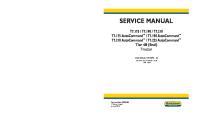
OUTLINE COOLANT FLOW DIAGRAM
ZCF360201004W03
F2, G6
E
ZBE3602W001
WL, WL TURBO
ZBE3602W003
1
Coolant reservoir
6
Cylinder block
2
Radiator
7
Cylinder head
3
Thermostat
8
Heater
4
Water pump
9
Turbocharger
5
Oil cooler
E-3
Form No.F175-10-01I
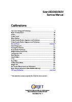
OUTLINE WL-3, WLT-3
ZBE3602W002
1
Coolant reservoir
6
Cylinder block
2
Radiator
7
Cylinder head
3
Thermostat
8
Heater
4
Water pump
9
Turbocharger
5
Oil cooler
10
EGR water cooler
E-4
Form No.F175-10-01I
FUEL AND EMISSION CONTROL SYSTEMS FEATURES OUTLINE . . . . . . . . . . . . . . . . . . . . . . . . . . . . . . . . . F2-3 OUTLINE OF CONSTRUCTION . . . . . . . . . . . . F2-3 FEATURES . . . . . . . . . . . . . . . . . . . . . . . . . . . . . . F2-3 SPECIFICATIONS . . . . . . . . . . . . . . . . . . . . . . . . F2-4 CONTROL SYSTEM DIAGRAM . . . . . . . . . . . . F2-4 CONTROL SYSTEM WIRING DIAGRAM . . . . F2-6 INTAKE-AIR SYSTEM . . . . . . . . . . . . . . . . . . . . . F2-9 OUTLINE . . . . . . . . . . . . . . . . . . . . . . . . . . . . . . . . F2-9 TURBOCHARGER DESCRIPTION . . . . . . . . . . F2-9 GLOW PLUG DESCRIPTION . . . . . . . . . . . . . . F2-10 ACCELERATOR PEDAL COMPONENT DESCRIPTION . . . . . . . . . . . . . . . . . . . . . . . . . F2-10 FUEL SYSTEM . . . . . . . . . . . . . . . . . . . . . . . . . . . F2-11 OUTLINE . . . . . . . . . . . . . . . . . . . . . . . . . . . . . . . F2-11 STRUCTUAL VIEW . . . . . . . . . . . . . . . . . . . . . . F2-11 SYSTEM DIAGRAM . . . . . . . . . . . . . . . . . . . . . . F2-12 INJECTION PUMP DESCRIPTION . . . . . . . . . F2-12 OVERFLOW VALVE DESCRIPTION . . . . . . . F2-14 ELECTRONIC GOVERNOR DESCRIPTION . F2-15 TIMER CONTROL VALVE DESCRIPTION . . F2-16 EMISSION SYSTEM . . . . . . . . . . . . . . . . . . . . . . F2-17 OUTLINE . . . . . . . . . . . . . . . . . . . . . . . . . . . . . . . F2-17 STRUCTURAL VIEW . . . . . . . . . . . . . . . . . . . . . F2-17 SYSTEM DIAGRAM . . . . . . . . . . . . . . . . . . . . . . F2-18 EGR SYSTEM . . . . . . . . . . . . . . . . . . . . . . . . . . . F2-18 EGR SORENOID VALVE (VACUUM, VENT) DESCRIPTION . . . . . . . . . . . . . . . . . . . . . . . . . F2-19 EGR CONTROL SOLENOID VALVE DESCRIPTION . . . . . . . . . . . . . . . . . . . . . . . . . F2-20 EGR WATER COOLER DESCRIPTION . . . . . F2-20 INTAKE SHUTTER VALVE DESCRIPTION . . F2-21 INTAKE SHUTTER SOLENOID VALVE DESCRIPTION . . . . . . . . . . . . . . . . . . . . . . . . . F2-21 CONTROL SYSTEM . . . . . . . . . . . . . . . . . . . . . . F2-22 OUTLINE . . . . . . . . . . . . . . . . . . . . . . . . . . . . . . . F2-22 STRUCTURAL VIEW . . . . . . . . . . . . . . . . . . . . . F2-22 BLOCK DIAGRAM . . . . . . . . . . . . . . . . . . . . . . . F2-24 CONTROL SYSTEM DEVICE AND CONTROL RELATIONSHIP CHART . . . . . . . . . . . . . . . . . F2-26 PCM DESCRIPTION . . . . . . . . . . . . . . . . . . . . . F2-27 MASS AIR FLOW (MAF)/INTAKE AIR TEMPERATURE (IAT) SENSOR DESCRIPTION . . . . . . . . . . . . . . . . . . . . . . . . . F2-27 INTAKE AIR TEMPERATURE (IAT) SENSOR NO.2 DESCRIPTION . . . . . . . . . . . . . . . . . . . . F2-28 FUEL TEMPERATURE SENSOR DESCRIPTION . . . . . . . . . . . . . . . . . . . . . . . . . F2-29 PUMP SPEED SENSOR DESCRIPTION . . . . F2-29 CONTROL SLEEVE (CS) SENSOR DESCRIPTION . . . . . . . . . . . . . . . . . . . . . . . . . F2-30 TIMER POSITION SENSOR DESCRIPTION F2-31 INJECTION PUMP EPROM DESCRIPTION . F2-31 TDC SENSOR DESCRIPTION . . . . . . . . . . . . . F2-32 EGR VALVE POSITION SENSOR DESCRIPTION . . . . . . . . . . . . . . . . . . . . . . . . . F2-32 BOOST SENSOR DESCRIPTION . . . . . . . . . . F2-33 PCM CONTROL RELAY DESCRIPTION . . . . F2-33 ACCELERATOR POSITION SENSOR DESCRIPTION . . . . . . . . . . . . . . . . . . . . . . . . . F2-34 IDLE SWITCH DESCRIPTION . . . . . . . . . . . . . F2-35
F2-1
Form No.F175-10-01I
CLUTCH SWITCH DESCRIPTION . . . . . . . . . NEUTRAL SWITCH DESCRIPTION . . . . . . . . FUEL INJECTION AMOUNT CONTROL . . . . FUEL INJECTION TIMING CONTROL . . . . . . EGR CONTROL . . . . . . . . . . . . . . . . . . . . . . . . . ON-BOARD DIAGNOSTIC . . . . . . . . . . . . . . . . OUTLINE . . . . . . . . . . . . . . . . . . . . . . . . . . . . . . . DTC . . . . . . . . . . . . . . . . . . . . . . . . . . . . . . . . . . . . PID/DATA MONITOR AND RECORD . . . . . . . SIMULATION TEST . . . . . . . . . . . . . . . . . . . . . .
F2-36 F2-36 F2-37 F2-39 F2-40 F2-42 F2-42 F2-42 F2-44 F2-45
SERVICE OUTLINE . . . . . . . . . . . . . . . . . . . . . . . . . . . . . . . . SUPPLEMENTAL SERVICE INFORMATION ENGINE TUNE-UP . . . . . . . . . . . . . . . . . . . . . . . ENGINE TUNEĆUP . . . . . . . . . . . . . . . . . . . . . . . INTAKE-AIR SYSTEM . . . . . . . . . . . . . . . . . . . . VACUUM TUBE ROUTING DIAGRAM . . . . . . TURBOCHARGER INSPECTION . . . . . . . . . . GLOW PLUG REMOVAL/INSTALLATION . . . GLOW PLUG INSPECTION . . . . . . . . . . . . . . . ACCELERATOR PEDAL COMPONENT REMOVAL/INSTALLATION . . . . . . . . . . . . . . . ACCELERATOR PEDAL COMPONENT DISASSEMBLY/ASSEMBLY . . . . . . . . . . . . . . FUEL SYSTEM . . . . . . . . . . . . . . . . . . . . . . . . . . . INJECTION PUMP INSPECTION . . . . . . . . . . FUEL SHUT OFF (FSO) SOLENOID INSPECTION . . . . . . . . . . . . . . . . . . . . . . . . . . . ELECTRONIC GOVERNOR INSPECTION . . TIMER CONTROL VALVE (TCV) INSPECTION . . . . . . . . . . . . . . . . . . . . . . . . . . . EMISSION SYSTEM . . . . . . . . . . . . . . . . . . . . . . EGR SYSTEM REMOVAL/INSTALLATION . . EGR VALVE INSPECTION . . . . . . . . . . . . . . . . EGR SOLENOID VALVE (VACUUM) INSPECTION . . . . . . . . . . . . . . . . . . . . . . . . . . . EGR SOLENOID VALVE (VENT) INSPECTION . . . . . . . . . . . . . . . . . . . . . . . . . . . EGR CONTROL SOLENOID VALVE INSPECTION . . . . . . . . . . . . . . . . . . . . . . . . . . . INTAKE SHUTTER VALVE ACTUATOR INSPECTION . . . . . . . . . . . . . . . . . . . . . . . . . . . INTAKE SHUTTER SOLENOID VALVE INSPECTION . . . . . . . . . . . . . . . . . . . . . . . . . . . CONTROL SYSTEM . . . . . . . . . . . . . . . . . . . . . . CONTROL SYSTEM COMPONENT . . . . . . . . PCM REMOVAL/INSTALLATION . . . . . . . . . . . PCM INSPECTION . . . . . . . . . . . . . . . . . . . . . . . MASS AIR FLOW (MAF)/INTAKE AIR TEMPERATURE (IAT) SENSOR INSPECTION . . . . . . . . . . . . . . . . . . . . . . . . . . . INTAKE AIR TEMPERATURE (IAT) SENSOR NO.2 INSPECTION . . . . . . . . . . . . . . . . . . . . . ENGINE COOLANT TEMPERATURE (ECT) SENSOR INSPECTION . . . . . . . . . . . . . . . . . . FUEL TEMPERATURE SENSOR INSPECTION . . . . . . . . . . . . . . . . . . . . . . . . . . . PUMP SPEED SENSOR INSPECTION . . . . . CONTROL SLEEVE (CS) SENSOR INSPECTION . . . . . . . . . . . . . . . . . . . . . . . . . . .
F2-46 F2-46 F2-47 F2-47 F2-48 F2-48 F2-48 F2-49 F2-50 F2-50 F2-51 F2-52 F2-52 F2-53 F2-54 F2-54 F2-55 F2-55 F2-56 F2-56 F2-56 F2-57 F2-57 F2-57 F2-59 F2-59 F2-60 F2-61 F2-65 F2-66 F2-66 F2-67 F2-68 F2-68
F2
OUTLINE TIMER POSITION SENSOR INSPECTION . . F2-69 INJECTION PUMP EPROM INSPECTION . . F2-69 TDC SENSOR REMOVAL/INSTALLATION . . F2-70 TDC SENSOR INSPECTION . . . . . . . . . . . . . . F2-70 EGR VALVE POSITION SENSOR INSPECTION . . . . . . . . . . . . . . . . . . . . . . . . . . . F2-70 BOOST SENSOR INSPECTION . . . . . . . . . . . F2-71 PCM CONTROL RELAY INSPECTION . . . . . F2-71 ACCELERATOR POSITION SENSOR INSPECTION . . . . . . . . . . . . . . . . . . . . . . . . . . . F2-71 ACCELERATOR POSITION SENSOR ADJUSTMENT . . . . . . . . . . . . . . . . . . . . . . . . . F2-72 IDLE SWITCH INSPECTION . . . . . . . . . . . . . . F2-73 IDLE SWITCH ADJUSTMENT . . . . . . . . . . . . . F2-73 CLUTCH SWITCH INSPECTION . . . . . . . . . . . F2-74 NEUTRAL SWITCH INSPECTION . . . . . . . . . F2-75 ON-BOARD DIAGNOSTIC . . . . . . . . . . . . . . . . F2-76 FOREWORD . . . . . . . . . . . . . . . . . . . . . . . . . . . . F2-76 OBD READ/CLEAR DIAGNOSTIC TEST RESULTS . . . . . . . . . . . . . . . . . . . . . . . . . . . . . . F2-76 OBD PARAMETER IDENTIFICATION (PID) ACCESS . . . . . . . . . . . . . . . . . . . . . . . . . . . . . . . F2-76 ONĆBOARD DIAGNOSTIC TEST . . . . . . . . . . F2-77 DTC TABLE . . . . . . . . . . . . . . . . . . . . . . . . . . . . . F2-77 DTC P0100 . . . . . . . . . . . . . . . . . . . . . . . . . . . . . F2-79 DTC P0105 . . . . . . . . . . . . . . . . . . . . . . . . . . . . . F2-82 DTC P0110 . . . . . . . . . . . . . . . . . . . . . . . . . . . . . . F2-84 DTC P0115 . . . . . . . . . . . . . . . . . . . . . . . . . . . . . . F2-87 DTC P0120 . . . . . . . . . . . . . . . . . . . . . . . . . . . . . F2-90 DTC P0180 . . . . . . . . . . . . . . . . . . . . . . . . . . . . . F2-93 DTC P0251 . . . . . . . . . . . . . . . . . . . . . . . . . . . . . F2-96 DTC P0335 . . . . . . . . . . . . . . . . . . . . . . . . . . . . . F2-98 DTC P0400 . . . . . . . . . . . . . . . . . . . . . . . . . . . . . F2-99 DTC P0500 . . . . . . . . . . . . . . . . . . . . . . . . . . . . F2-101 DTC P0510 . . . . . . . . . . . . . . . . . . . . . . . . . . . . F2-103 DTC P0606 . . . . . . . . . . . . . . . . . . . . . . . . . . . . F2-104 DTC P1110 . . . . . . . . . . . . . . . . . . . . . . . . . . . . . F2-105 DTC P1182 . . . . . . . . . . . . . . . . . . . . . . . . . . . . . F2-108 DTC P1189 . . . . . . . . . . . . . . . . . . . . . . . . . . . . . F2-109 DTC P1195 . . . . . . . . . . . . . . . . . . . . . . . . . . . . . F2-110 DTC P1226 . . . . . . . . . . . . . . . . . . . . . . . . . . . . F2-111 DTC P1312 . . . . . . . . . . . . . . . . . . . . . . . . . . . . F2-113 DTC P1318 . . . . . . . . . . . . . . . . . . . . . . . . . . . . F2-115 DTC P1402 . . . . . . . . . . . . . . . . . . . . . . . . . . . . F2-117 DTC P1602 . . . . . . . . . . . . . . . . . . . . . . . . . . . . F2-120 DTC P1603 . . . . . . . . . . . . . . . . . . . . . . . . . . . . F2-122 DTC P1604 . . . . . . . . . . . . . . . . . . . . . . . . . . . . F2-123 DTC P1621 . . . . . . . . . . . . . . . . . . . . . . . . . . . . F2-123 DTC P1622 . . . . . . . . . . . . . . . . . . . . . . . . . . . . F2-124 DTC P1623 . . . . . . . . . . . . . . . . . . . . . . . . . . . . F2-124 DTC P1624 . . . . . . . . . . . . . . . . . . . . . . . . . . . . F2-125 DTC P1649 . . . . . . . . . . . . . . . . . . . . . . . . . . . . F2-125 TROUBLESHOOTING . . . . . . . . . . . . . . . . . . . . F2-128 FORWORD . . . . . . . . . . . . . . . . . . . . . . . . . . . . F2-128 INTERMITTENT CONCERN TROUBLESHOOTING . . . . . . . . . . . . . . . . . . F2-128 TROUBLESHOOTING ITEM TABLE . . . . . . . F2-129 QUICK DIAGNOSIS CHART . . . . . . . . . . . . . F2-131 NO.1 MELTING OF MAIN OR OTHER FUSES . . . . . . . . . . . . . . . . . . . . . . . . . . . . . . . F2-134 NO.2 WILL NOT CRANK . . . . . . . . . . . . . . . . . F2-134 NO.3 HARD TO START/LONG CRANK/ERRATIC START/ERRATIC CRANK . . . . . . . . . . . . . . . F2-135 NO.4 ENGINE STALLSĆAFTER START/AT IDLE . . . . . . . . . . . . . . . . . . . . . . . F2-136
NO.5 CRANKS NORMALLY BUT WILL NOT START . . . . . . . . . . . . . . . . . . . . . . . . . . . F2-140 NO.6 SLOW RETURN TO IDLE/FAST IDLE F2-142 NO.7 ENGINE RUNS ROUGH/ROLLING IDLE . . . . . . . . . . . . . . . . . . . . . . . . . . . . . . . . . F2-143 NO.8 RUNS ON . . . . . . . . . . . . . . . . . . . . . . . . F2-145 NO.9 ENGINE STALLS/QUITS, ENGINE RUNS ROUGH, MISSES, BUCK/JERK, HESITATION/STUMBLE, SURGES . . . . . . F2-145 NO.10 LACK/LOSS OF POWER . . . . . . . . . . F2-147 NO.11 POOR FUEL ECONOMY . . . . . . . . . . F2-149 NO.12 HIGH OIL CONSUMPTION/LEAKAGE . . . . . . . . . . . . . F2-151 NO.13 COOLING SYSTEM CONCERNSĆOVERHEATING . . . . . . . . . . . F2-152 NO.14 COOLING SYSTEM CONCERNSĆRUNS COLD . . . . . . . . . . . . . . . . . . . . . . . . . . . . . . . . F2-153 NO.15 EXCESSIVE BLACK SMOKE . . . . . . F2-153 NO.16 ENGINE NOISE . . . . . . . . . . . . . . . . . . F2-154 NO.17 VIBRATION CONCERNS (ENGINE) F2-156 NO.18 A/C DOES NOT WORK SUFFICIENTLY . . . . . . . . . . . . . . . . . . . . . . . . F2-156 NO.19 A/C ALWAYS ON OR A/C COMPRESSOR RUNS CONTINUOUSLY . . . . . . . . . . . . . . . . F2-157 NO.20 INTERMITTENT CONCERNS . . . . . . F2-158 NO.21 CONSTANT VOLTAGE . . . . . . . . . . . . F2-159
F2-2
Form No.F175-10-01I
OUTLINE
OUTLINE OUTLINE OF CONSTRUCTION
ZCF400202000W01
D To match the Euro 3 Regulation, WL-3 and WLT-3 models have been adopted which have electronic control type injection pump. D The construction and operation of the fuel and emission control systems of the Euro 3 Regulation models is essentially carried over from that of the current RANGER (UN)/RANGER WL, WL Turbo models (nonĆEuro 3 regulation models.) (See RANGER TRAINING MANUAL F326-10-99A.) except for the following features. D Euro 3 and non Euro 3 regulation models are distinguished as follows: Ċ Euro 3 Regulation models are equipped with an EGR water cooler in the engine room. Ċ NonĆEuro 3 Regulation models are not equipped with an EGR water cooler in the engine room.
F2
ZCF4002W004
1
EGR water cooler
FEATURES
ZCF400202000W02
Improved Emission Performance D An electric controlled type injection pump has been adopted on the Euro 3 Regulation models. D An EGR valve position sensor has been added to the Euro 3 Regulation model. D An EGR water cooler has been added to the Euro 3 Regulation models. D An intake shutter valve has been added to the Euro 3 Regulation WLT-3 engine models. D A turbocharger that is smaller than the WL Turbo engine has been added on the Euro 3 Regulation WL-3 models. Improved Drivability D A turbocharger that is smaller than the WL Turbo engine has been adopted on the Euro 3 Regulation WL-3 models. Improved Serviceability D DTCs have been added to Euro 3 Regulation models. D PID DATA MONITOR and SIMULATION functions have been added to the Euro 3 Regulation models, using WDS or equivalent.
F2-3
Form No.F175-10-01I
OUTLINE SPECIFICATIONS
ZCF400202000W03
Euro 3 Regulation models
Item
WLĆ3
Non Euro 3 Regulation models
WLTĆ3
WL
Air cleaner element
Type
Supercharger type
Type
Turbocharger with charge air cooler
Glow plug
Type
Ceramic type
Injection pump
Type
Fuel tank
Non woven fabric (dry)
EGR control
Type
Turbocharger with charge air cooler
SelfĆtemperature control type
63 {67, 55}*1,70 {74, 62}
(L {US gal, lmp gal}) Type
Ć
Bosch VE distributor
Capacity
Catalyst
WL Turbo
Oxidation catalyst converter Duty control type
Ć
PCV system Type *1 : Stretch cab 2WD Bold frames : New specifications
ON/OFF
Closed type
CONTROL SYSTEM DIAGRAM
ZCF400202000W04
Euro 3 Regulation Models
ZCF4002W001
1
PCM
7
Intake shutter valve actuator
2
Air cleaner
8
Intake manifold
3
Turbocharger
9
Glow plug
4
Intake shutter solenoid valve
10
WLĆ3
5
Charge air cooler
11
Fuel tank
6
Intake shutter valve
12
Sedimentor switch
F2-4
Form No.F175-10-01I
OUTLINE 13
Fuel filter
34
CS sensor
14
Fuel warmer (if equipped)
35
Electronic govenor
15
Injection pump
36
Injection pump EPROM
16
Injection nozzle
37
FSO solenoid
17
Wastegate dumper
38
TCV
18
Oxidation catalytic converter
39
Timer position sensor
19
EGR valve
40
Pump speed sensor
20
EGR valve position sensor
41
Accelerator position sensor
21
EGR solenoid valve (vent)
42
Idle switch
22
EGR solenoid valve (vacuum)
43
Barometric pressure sensor
23
EGR control solenoid valve
44
Engine switch
24
EGR water cooler
45
Starter (starter signal)
25
Vacuum pump
46
A/C switch
26
Glow plug relay
47
VSS
27
To battery
48
DLC (TEN)
28
IAT sensor No.2
49
Neutral switch
29
Boost sensor
50
Clutch switch
30
TDC sensor
51
WLTĆ3
31
ECT sensor
52
MAF/IAT sensor
32
PCM control relay
53
To PCM
33
Fuel temperature sensor
F2-5
Form No.F175-10-01I
F2
OUTLINE CONTROL SYSTEM WIRING DIAGRAM
ZCF400202000W05
Euro 3 Regulation Models
ZCF4002W002
F2-6
Form No.F175-10-01I
OUTLINE
F2
ZCF4002W003
1
PCM
6
EGR solenoid valve (vent)
2
DLC
7
Intake shutter solenoid valve
3
Neutral switch
8
WLT-3 engine only
4
Clutch switch
9
Immobilizer unit
5
EGR solenoid valve (vacuum)
10
Engine switch
F2-7
Form No.F175-10-01I
OUTLINE 11
Battery
31
TDC sensor
12
Starter
32
Timer position sensor
13
Generator
33
Injection pump EPROM
14
Instrument cluster
34
PCM control relay
15
Generator warning light
35
EGR control solenoid valve
16
Sedimentor switch
36
Idle switch
17
Oil pressure switch
37
MAF/IAT sensor
18
Heat gauge unit
38
ECT sensor
19
Vehicle speedometer sensor
39
IAT sensor No.2
20
VSS
40
Glow plug relay
21
Glow indicator light
41
Glow plug
22
Boost sensor
42
Vacuum switch
23
EGR valve position sensor
43
Fuel warmer
24
Accelerator position sensor
44
With fuel warmer
25
FSO solenoid
45
A/C relay
26
TCV
46
A/C amplifier
27
Fuel temperature sensor
47
A/C switch
28
CS sensor
48
Blower motor relay
29
Electronic governor
49
Fan switch
30
Pump speed sensor
50
Sedimentor warning light
F2-8
Form No.F175-10-01I
INTAKE-AIR SYSTEM
INTAKE-AIR SYSTEM OUTLINE
ZCF401001005W01
Euro 3 Regulation Models D The construction and operation of the intake-air system of the Euro 3 Regulation models is essentially carried over from that of the current RANGER (UN)/RANGER WL, WL Turbo models, except for following. (See RANGER TRAINING MANUAL F326-10-99A.) Ċ A small size turbocharger comparable to the one on the previous WL Turbo model has been adopted on the WL-3 models to improve response and engine torque at low/middle speeds. Ċ An intake shutter valve has been installed on the intake manifold to improve emission performance. (WLT-3 models) Ċ A ceramic type glow plug has been adopted to improve emission performance when starting under cold conditions. TURBOCHARGER DESCRIPTION
ZCF401013700W01
Euro 3 Regulation Models (WL-3) Outline D To improve emission performance and engine power in conformance to the Euro 3 regulation, a turbocharger has been added to the existing WL engine type. D Compared to the WLT-3 engine turbocharger, smaller turbine wheels have been adopted, improving response and engine torque at low/middle speeds. Function D The turbocharger uses exhaust gas pressure to compress the intake air. Structure/operation D A wastegate valve, an exhaust-pressure control type valve with a simple structure, has been adopted. D When exhaust pressure is low, the wastegate valve is closed by spring resistance from the wastegate damper spring. D When exhaust pressure from the exhaust manifold exceeds the set value, the wastegate valve overcomes spring resistance of the wastegate damper. As a result, the exhaust pressure is released to the turbine wheel downstream and the air charging pressure is controlled.
ZCF4010W101
1
Low exhaust-pressure
4
Wastegate valve
2
Exhaust-pressure exceeds set value
5
Turbocharger
3
Wastegate dumper
6
Exhaust gas flow
F2-9
Form No.F175-10-01I
F2
INTAKE-AIR SYSTEM GLOW PLUG DESCRIPTION
ZCF401018601W01
Euro 3 Regulation Models Function D Glow plug improves ignitability and combustibility of intake air by generating heat. Structure/Operation D Ceramic material is used on the glow area end for selfĆcontrol of heat.
ZCF4010W011
1
Glow plug
2
Glow area end
ACCELERATOR PEDAL COMPONENT DESCRIPTION
ZCF401041600W01
Euro 3 Regulation Models Structure D Accelerator pedal components consist of an accelerator pedal, idle switch, and accelerator position sensor.
ZCF4010W012
1
Accelerator position sensor
2
Idle switch
3
F2-10
Form No.F175-10-01I
Accelerator pedal
FUEL SYSTEM
FUEL SYSTEM OUTLINE
ZCF401201006W01
Euro 3 Regulation Models D The construction and operation of the fuel system of the Euro 3 Regulation models is essentially carried over from that of the current RANGER (UN)/RANGER WL, WL Turbo models, except for following. (See RANGER TRAINING MANUAL F326-10-99A.) Ċ An electronic control type injection pump has been adopted to improve the emission performance. STRUCTUAL VIEW
ZCF401201006W02
Euro 3 Regulation Models
ZCF4012W020
1
Injection pump
6
Fuel filter
2
Electronic governor
7
Injection nozzle
3
TCV
8
Sedimentor switch
4
FSO solenoid
9
Fuel warmer (if equipped)
5
Overflow valve
F2-11
Form No.F175-10-01I
FUEL SYSTEM SYSTEM DIAGRAM
ZCF401201006W03
Euro 3 Regulation Models
ZCF4012W011
1
Fuel tank
7
FSO solenoid
2
Fuel filter
8
Overflow valve
3
Injection pump
9
Fuel warmer (if equipped)
4
Injection nozzle
10
Sedimentor switch
5
Electronic governor
11
Fuel flow
6
TCV
INJECTION PUMP DESCRIPTION
ZCF401213800W01
Euro 3 Regulation Models Outline D Due to the adoption of the electronic control type injection pump, the PCM electrically controls the adjustment of the fuel injection amount and timing, which has been controlled mechanically in nonĆ Euro 3 regulation models. The PCM detects the engine driving condition according to the input signals from the sensors, and determines the optimal fuel injection amount and timing. Function D The injection pump distributes and force feeds the fuel to the injection nozzle with the optimal injection amount and timing according to the engine condition.
F2-12
Form No.F175-10-01I
FUEL SYSTEM Structure D The electronic control type injection pump consists of a pump mechanism, which has the same construction as the conventional mechanical injection pump, and electronic control parts such as an electronic governor and a timer control valve.
ZCF4012W013
1
Injection pump crossĆsectional view
3
Pump mechanism
2
Electronic governor
4
Timer control valve
Operation Injection amount adjustment D As with the conventional mechanical injection pump, the fuel is increased or decreased by moving the control sleeve and changing the injection end timing. When the control sleeve moves to the left, the effective stroke, which determines the injection amount, is reduced and the injection amount is also reduced. On the other hand, when the control sleeve moves to the right, the effective stroke increases and the injection amount also increases. D In the electronic control type injection pump, the control sleeve position is moved by the electronic governor.
ZCF4012W014
1
Control sleeve
4
Fuel decrease
2
Plunger
5
Fuel increase
3
Effective stroke
F2-13
Form No.F175-10-01I
FUEL SYSTEM Injection Timing Adjustment D As with the conventional mechanical injection pump, the fuel injection timing is determined by moving the timer piston to change the relative position of the roller holder that contacts the cam plate. D In the electronic control type injection pump, the fuel pressure that actuates the timer piston is controlled by the timer control valve.
ZCF4012W015
1
Timer control valve
3
Roller holder
2
Timer piston
4
Cam plate
OVERFLOW VALVE DESCRIPTION
ZCF401213800W02
Euro 3 Regulation Models Function D The overflow valve maintains a constant fuel pressure in the pump chamber to stabilize the pressure when the fuel is drawn to the high pressure chamber and ensures the optimal fuel injection amount. Structure/Operation D The overflow valve is installed on the end face (injection side) of the electronic governor cover.The check valve contains a ball and spring which regulates the pressure in the pump chamber and prevents overflow from occuring through the set force of the spring.
ZCF4012W016
1
Overflow valve crossĆsectional view
4
Check ball
2
From pump chamber
5
Spring
3
To fuel tank
F2-14
Form No.F175-10-01I
FUEL SYSTEM ELECTRONIC GOVERNOR DESCRIPTION
ZCF401213800W03
Euro 3 Regulation Models Structure D The electronic governor is installed on the upper part of the injection pump and consists of a coil, rotor, shaft, and control sleeve (CS) sensor.
ZCF4012W018
1
Electronic governor crossĆsectional view
7
Shaft
2
Coil
8
Control sleeve
3
Control sleeve (CS) sensor
9
Ball pin
4
Return spring
10
Magnet filter
5
Rotor
11
Governor chamber
6
Core
Operation D In contrast to the current type of injection pump, this injection pump adjusts the injection amount electromagnetically. The control sleeve (CS) sensor detects the control sleeve position and sends feedback to the PCM. D When electricity passes through the coil, the core becomes magnetized, and the rotor rotates within the regulated limit. The strength of the magnetization is determined by the input flow of electricity. The magnetic force which occurs in the core causes the rotor to rotate until it balances with the return spring's tension. D The governor chamber and pump chamber are connected through the magnet filter, and the coil is cooled by the flow of fuel into the governor chamber. The magnet filter prevents the entry of steel chips into the electronic governor. D On the tip of the shaft, which is pressed in the rotor, a ball pin is installed eccentrically against the shaft. The ball pin is inserted in the control sleeve hole and the control sleeve position is moved when the rotor is rotated. D When the electric current output from the PCM as fuel injection amount is large, the electric current that flows in the coil also increases, widening the rotation angle of the rotor. As a result, the control sleeve position moves in the direction that fuel injection amount increases (right side).
F2-15
Form No.F175-10-01I
FUEL SYSTEM
ZCF4012W019
1
Magnetized
6
Shaft
2
Core
7
Ball pin
3
Rotor
8
Control sleeve
4
Coil
9
Fuel decrease
5
Electricity passes
10
Fuel increase
TIMER CONTROL VALVE DESCRIPTION
ZCF401213800W04
Euro 3 Regulation Models Function D The TCV is mounted to the bottom of the injection pump. The TCV is a solenoid valve that controls the position of the timer piston that modifies the fuel injection timing. Structure/Operation D The TCV is located between the oil passages that connect the highĆand lowĆpressure chambers. The TCV opens and closes the sheet part of the end of the needle in the TCV with the control signal (duty signal) from the PCM, and adjusts the timer piston position by adjusting the fuel pressure of the highĆpressure chamber. (Valve open: toward retard; valve closed: toward advance)
ZCF4012W017
1
Injection pump
2
TCV
3
Timer position sensor
4
Roller holder
5
LowĆpressure chamber
6
HighĆpressure chamber
7
Timer piston D A side: retard D B side: advance
F2-16
Form No.F175-10-01I
EMISSION SYSTEM
EMISSION SYSTEM OUTLINE
ZCF401601007W01
Euro 3 Regulation Models D The construction and operation of the emission system of the Euro 3 Regulation models is essentially carried over from that of the current RANGER (UN)/RANGER WL, WL Turbo models, except for following. (See RANGER TRAINING MANUAL F326-10-99A.) Ċ The EGR system has been strengthened to comform to the Euro 3 Regulation. D An intake shutter valve has been adopted. (WLT-3) D An EGR water cooler has been adopted. D An EGR valve control type for WL-3 and WLT-3 has been changed from ON/OFF control type which is used for current WL and WL Turbo, to duty control using EGR solenoid valves. (vent and vacuum.) STRUCTURAL VIEW
ZCF401601007W02
Euro 3 Regulation Models
ZCF4016W013
1
EGR valve
5
EGR solenoid valve (vent)
2
Intake shutter valve (WLTĆ3)
6
EGR control solenoid valve
3
EGR water cooler
7
Intake shutter solenoid valve (WLTĆ3)
4
EGR solenoid valve (vacuum)
8
Air filter
F2-17
Form No.F175-10-01I
EMISSION SYSTEM SYSTEM DIAGRAM
ZCF401601007W03
Euro 3 Regulation Models
ZCF4016W014
1
EGR valve
7
WLTĆ3
2
EGR solenoid valve (vent)
8
Intake shutter solenoid valve
3
EGR solenoid valve (vacuum)
9
Intake shutter valve actuator
4
EGR control solenoid valve
10
Intake shutter valve
5
EGR water cooler
11
Oxidation catalytic converter
6
Vacuum pump
12
To PCM
EGR SYSTEM
ZCF401601075W01
Euro 3 Regulation Models Outline D An intake shutter valve has been adopted upstream of the intake manifold where the exhaust gas is introduced. D By closing the intake shutter valve and generating vacuum in the intake manifold during exhaust gas introduction, the gas is led to the combustion chamber efficiently and the amount of NOx has been reduced. D The newly adopted EGR water cooler cools EGR gas and improves the intakeĆair charging efficiency, reducing black smoke. Operation D To open the EGR valve and increase the EGR amount, increase the EGR solenoid valve (vacuum) control duty valve to increase the vacuum applied to the EGR valve. To close the EGR valve to decrease the EGR amount, increase the EGR solenoid valve (vent) control duty valve to decrease the vacuum applied to the EGR valve. D When the PCM energizes the intake shutter solenoid valve during the exhaust gas introduction at low engine speed, the vacuum passage is opened and vacuum is applied to the intake shutter valve actuator. Due to this, the intake shutter valve is closed and vacuum is generated downstream of the intake manifold after the intake shutter valve, realizing easier introduction of the exhaust gas to the combustion chamber.
F2-18
Form No.F175-10-01I
EMISSION SYSTEM System diagram
ZCF4016W015
1
EGR valve
7
Intake shutter solenoid valve
2
EGR solenoid valve (vent)
8
Intake shutter valve actuator
3
EGR solenoid valve (vacuum)
9
Intake shutter valve
4
EGR control solenoid valve
10
WLTĆ3
5
EGR water cooler
11
To PCM
6
Vacuum pump
EGR SORENOID VALVE (VACUUM, VENT) DESCRIPTION
ZCF401618741W01
Euro 3 Regulation Models Function D EGR solenoid valve (vacuum) and EGR solenoid valve (vent) open/close the passage which brings vacuum generated in the vacuum pump to the diaphragm, and control the EGR valve opening. Structure/Operation D Vent side solenoid valve is connected to the EGR valve diaphragm through EGR control solenoid valve, and the vacuum side solenoid valve is connected to vacuum pump. D Solenoid valve consists of a solenoid coil, spring, plunger and air filter. D Vacuum side solenoid valve increases the angle of the valve opening by increasing vacuum on EGR valve via the EGR control signal (duty signal). D Vent side solenoid valve decreases the angle of the valve opening by releasing vacuum on EGR valve via the EGR control signal (duty signal). D Based on the combination of the vent side and vacuum side solenoid valves, the EGR valve opening angle is controlled.
F2-19
Form No.F175-10-01I
EMISSION SYSTEM EGR CONTROL SOLENOID VALVE DESCRIPTION
ZCF401618741W04
Euro 3 Regulation Models Function D EGR valve changes the pressure on the diaphragm of the EGR valve from vacuum to atmospheric pressure. Structure/Operation D EGR control solenoid valve consists of coil, spring, and plunger. D When EGR valve is not energized, the passage between the diaphragm and atmospheric air side is open. D When specified conditions are satisfied, the solenoid coils become energized and electromagnetic, and then pull the plunger. At this time, the passage between the diaphragm and atmospheric air side is closed and the passage between the diaphragm and vacuum pump side is opened. EGR WATER COOLER DESCRIPTION
ZCF401620302W01
Euro 3 Regulation Models Function D EGR water cooler cools recircurated exhaust gas from the intake manifold. Structure/Operation D EGR water cooler has an EGR passage and coolant passage.
ZCF4016W012
1
EGR water cooler
4
EGR passage
2
Coolant flow
5
Coolant passage
3
Exhaust gas flow
F2-20
Form No.F175-10-01I
EMISSION SYSTEM INTAKE SHUTTER VALVE DESCRIPTION
ZCF401620100W01
Euro 3 Regulation Models (WLTĆ3) Function D When the exhaust gas recirculation system is operated, the intake shutter valve closes, vacuum is generated in the intake manifold, and EGR gas is efficiently transported to the combustion chamber. As a result, NOx is reduced. D When the engine is idling, the intake shutter valve closes and reduces air intake noise. Structure/Operation D When the exhaust gas recirculation system is operated and vacuum is applied to the diaphragm of the intake shutter valve actuator, the internal lever is pulled and the intake shutter valve closes.
ZCF4016W011
1
Intake shutter valve
2
Intake shutter valve actuator
3
Intake manifold
INTAKE SHUTTER SOLENOID VALVE DESCRIPTION
ZCF401613937W01
Euro 3 Regulation Models (WLTĆ3) Function D The intake shutter solenoid valve switches the opening/closing of the passage where the vacuum generated in the vacuum pump is led to the diaphragm of the intake shutter valve actuator. Structure D The intake shutter solenoid valve consists of a solenoid coil, a spring, a plunger, etc. Operation D The vacuum passage between the intake shutter valve actuator and the vacuum pump is opened or closed depending upon whether the intake shutter solenoid valve is energized or deĆenergized.
F2-21
Form No.F175-10-01I
CONTROL SYSTEM
CONTROL SYSTEM OUTLINE
ZCF404001070W01
Euro 3 Regulation Models D The construction and operation of the control system of the Euro 3 Regulation models is essentially carried over from that of the current RANGER (UN)/RANGER WL, WL Turbo models, except for following. (See RANGER TRAINING MANUAL F326-10-99A.) Ċ Fuel injection amount control has been adopted to improve emission performance. Ċ Fuel injection timing control has been adopted to improve emission performance. Ċ The EGR valve control type for Euro 3 Regulation models has been changed from previous ON/OFF control type to duty control using EGR solenoid valves (vent and vacuum). Ċ Due to the adoption of the electronic control type injection pump, the immobilizer control has been modified. STRUCTURAL VIEW
ZCF404001070W02
Euro 3 Regulation Models
ZCF4040W045
F2-22
Form No.F175-10-01I
CONTROL SYSTEM 1
PCM (integrated with barometric pressure sensor)
14
Timer position sensor
2
MAF/IAT sensor
15
Control sleeve (CS) sensor
3
IAT sensor No.2
16
EGR position sensor
4
Boost sensor
17
Glow plug relay
5
ECT sensor
18
PCM control relay
6
TDC sensor
19
A/C relay
7
Accelerator position sensor
20
DLC
8
Idle switch
21
Battery
9
Clutch switch
22
A/C switch
10
Fuel temperature sensor
23
Engine switch
11
Pump speed sensor
24
Starter
12
Injection pump EPROM
25
Glow indicator light
13
Timer control valve
26
Neutral switch
F2-23
Form No.F175-10-01I
CONTROL SYSTEM BLOCK DIAGRAM
ZCF404001070W03
Euro 3 Regulation Models
ZCF4040W100
1
Fuel injection amount control
6
FSO solenoid
2
Fuel injection timing control
7
Electronic governor
3
Idle speed control
8
CS sensor
4
Glow control
9
A/C cut-off control
5
EGR control
10
Immobilizer system
F2-24
Form No.F175-10-01I
CONTROL SYSTEM 11
MAF/IAT sensor
26
Battery
12
ECT sensor
27
DLC
13
Accelerator position sensor
28
Starter (starter signal)
14
Idle switch
29
Barometric pressure sensor (integrated in PCM)
15
IAT sensor No.2
30
Timer position sensor
16
Pump speed sensor
31
EGR valve position sensor
17
Fuel temperature sensor
32
Timer control valve
18
Injection pump EPROM
33
EGR solenoid valve (vacuum)
19
TDC sensor
34
EGR solenoid valve (vent)
20
Boost sensor
35
EGR control solenoid valve
21
Neutral switch
36
Glow indicator light (instrument cluster)
22
Clutch switch
37
Glow plug relay
23
VSS
38
A/C relay
24
A/C switch
39
PCM
25
Immobilizer unit (with immobilizer system)
40
Intake shutter solenoid valve (WLTĆ3)
F2-25
Form No.F175-10-01I
CONTROL SYSTEM CONTROL SYSTEM DEVICE AND CONTROL RELATIONSHIP CHART
ZCF404001070W04
Euro 3 Regulation Models
ZCF4040W046
F2-26
Form No.F175-10-01I
CONTROL SYSTEM PCM DESCRIPTION
ZCF404018880W01
Euro 3 Regulation Models Function D Based on the signal from each input sensor, the PCM outputs a drive (operation) signal to the drive parts (solenoid, etc.), which require an optimum control amount according to the engine condition (engine speed, engine coolant temperature, etc.). D The PCM is located in the underfoot area of the right side seat.
ZCF4040W035
MASS AIR FLOW (MAF)/INTAKE AIR TEMPERATURE (IAT) SENSOR DESCRIPTION
ZCF404013210W01
Euro 3 Regulation Models Structure D A hot-wire type MAF sensor is used. D IAT sensor No.1 has integrated into the MAF/IAT sensor.
ZCF4040W037
1
MAF sensor
9
Cold wire
2
IAT sensor No.1
10
Intake airflow
3
MAF sensor power supply
11
From PCM control relay
4
MAF sensor GND
12
Comparison circuit
5
MAF sensor output
13
Constant resistor
6
IAT sensor No.1 output
14
PCM
7
IAT sensor No.1 GND
15
CPU
8
Hot wire
F2-27
Form No.F175-10-01I
CONTROL SYSTEM Operation D The hot-wire (heat resistor) type MAF sensor detects the mass intake airflow that corresponds to the output current. D The output current is controlled by the control circuit in the MAF sensor and heats the hot wire (heat resistor) so that the temperature difference between the heat resistor and the intake air is constant. D The output current required to maintain the heat resistor temperature is proportional to the intake airflow volume. The output current characteristic against the mass intake airflow is as shown in the figure below. D The cold wire (cold resistor) corrects the variation in resistance of the hot wire (heat resistor) which is caused by the intake air temperature.
Y6E4040W014
1
Mass intake airflow
3
Low
2
Output current
4
High
INTAKE AIR TEMPERATURE (IAT) SENSOR NO.2 DESCRIPTION
ZCF404018845W01
Euro 3 Regulation Models Function D The intake air sensor No.2 is installed in the air pipe between the charge air cooler and the intake manifold. By utilizing a thermistor of which resistance varies with supercharged air temperature, the sensor detects temperature in the intake manifold. D The detected intake air temperature is used for correction of fuel injection amount control.
ZCF4040W036
1
IAT sensor No.2
2
Detecting part
3
F2-28
Form No.F175-10-01I
Connector
CONTROL SYSTEM FUEL TEMPERATURE SENSOR DESCRIPTION
ZCF404013809W01
Euro 3 Regulation Models Function D The fuel temperature sensor is built into the electronic governor at the top of the injection pump. The fuel temperature sensor detects the fuel temperature required for correction of the fuel injection amount according to the change in the thermistor's resistance value and sends it to the PCM. D The resistance characteristic of the fuel temperature sensor is as shown.
ZCF4040W038
1
Injection pump
5
Low
2
Fuel temperature sensor
6
High
3
High
7
Resistance
4
Low
8
Fuel temperature
PUMP SPEED SENSOR DESCRIPTION
ZCF404013801W01
Euro 3 Regulation Models Function D The pump speed sensor is mounted to the side of the injection pump and detects the engine speed with the sensor ring press-fitted to the drive shaft in the injection pump. Structure/Operation D The pump speed sensor detects the alternating voltage produced by the change in the magnetic field of the projection on the sensor ring press-fitted to the drive shaft as an engine speed signal and as a cylinder discrimination signal. D The TDC sensor also detects the engine speed signal, but in the event that the TDC sensor malfunctions, the pump speed sensor detects the engine speed signal and inputs it to the PCM.
ZCF4040W040
1
Injection pump
2
F2-29
Form No.F175-10-01I
Pump speed sensor
CONTROL SYSTEM CONTROL SLEEVE (CS) SENSOR DESCRIPTION
ZCF404013805W01
Euro 3 Regulation Models Function D The CS sensor detects the control sleeve position and is used as a fuel injection amount feedback signal in the PCM. Structure/Operation D The CS sensor is mounted to the top of the electronic governor. D The CS sensor consists of a sleeve position detection part and a temperature correction part. The sleeve position detection part has a movable plate which rotates with the sensor coil and the governor shaft, and modifies the strength of the sensor coil's magnetic field according to the rotation of the movable plate (control sleeve position). The temperature correction part has a temperature correction coil and a fixed plate, and modifies the strength of the correction coil's magnetic field according to the temperature. D Basically, the CS sensor detects the sleeve position depending on the change in strength of the sensor coil's magnetic field. However, the strength of the magnetic field will also change depending on the temperature of the coil. As a result, the CS sensor, by constantly comparing and correcting the opposing temperature correction coil's magnetic field, calculates an accurate rotation angle as a voltage and thereby detects the control sleeve position.
ZCF4040W041
1
Injection pump
2
F2-30
Form No.F175-10-01I
CS sensor
CONTROL SYSTEM TIMER POSITION SENSOR DESCRIPTION
ZCF404013807W01
Euro 3 Regulation Models Function D The timer position sensor detects the timer piston position and is used as a fuel injection timing feedback signal in the PCM Structure/Operation D The timer position sensor is mounted to the low pressure chamber side and consists of a core rod, a coil, and a bobbin D The core rod is mounted to the timer piston. The core rod moves the middle of the coil with the timer piston to change the strength of the coil's magnetic field and detects this voltage change as the timer piston position.
ZCF4040W044
1
Injection pump
5
Core rod
2
Timer control valve
6
Coil
3
Timer position sensor
7
LowĆpressure chamber
4
Bobbin
8
Timer piston
INJECTION PUMP EPROM DESCRIPTION
ZCF404013802W01
Euro 3 Regulation Models Function D For accurate fuel injection control, injection pump production variance/mechanical variance is added to injection pump EPROM as a correction value. Structure/Operation D Injection pump EPROM is installed on the top of injection pump. D Injection pump EPROM varies in characteristics. When there is any malfunction, contact the injection pump supplier, Bosch Automotive Systems Corporation for repair.
ZCF4040W049
1
Injection pump EPROM
F2-31
Form No.F175-10-01I
CONTROL SYSTEM TDC SENSOR DESCRIPTION
ZCF404018230W01
Euro 3 Regulation Models Function D TDC sensor detects crankshaft speed signal. Structure/Operation D TDC sensor is installed near crankshaft pulley. D TDC sensor is a hall-element type and it detects hall voltage generated by the change in magnetic flux of the magnet inside the sensor and hall element as the crankshaft speed signal. D Crankshaft speed signal is detected directly from the fin and window area on the plate. D TDC sensor also detects the engine speed signal and inputs it to the PCM in case the pump speed sensor has a malfunction in detecting the engine speed signal.
ZCF4040W048
1
TDC sensor
4
Plate
2
Window area
5
View A
3
Fin area
EGR VALVE POSITION SENSOR DESCRIPTION
ZCF404020300W01
Euro 3 Regulation Models Function D The EGR valve position sensor measures EGR valve lift amount and sends signal to the PCM, allowing the PCM to diagnose a EGR system malfunction when there is a discrepancy between target and actual opening angles of the EGR valve.
ZCF4040W058
1
EGR valve
2
EGR valve position sensor
3
F2-32
Form No.F175-10-01I
PCM
CONTROL SYSTEM BOOST SENSOR DESCRIPTION
ZCF404018660W01
Euro 3 Regulation Models Function D The boost sensor detects the intake air pressure as an absolute pressure, and sends it to the PCM as an intake air pressure signal. D The boost sensor is installed in the air pipe between the charge air cooler and the intake manifold. Operation D The boost sensor is filled with crystal (silicon) and it is the semi-conductor pressure sensor which utilizes the characteristic of the electrical resistance that changes when the crystal is pressurized. *Absolute pressure is the pressure when vacuum is set as 0 kPa {0 mmHg, 0 inHg}.
ZCF4040W029
1
Boost sensor
4
Output voltage
2
Vacuum chamber (Integrated with a silicon chip)
5
Sensor output characteristic
3
Supercharged pressure
6
pressure
PCM CONTROL RELAY DESCRIPTION
ZCF404018880W04
Euro 3 Regulation Models Operation D The PCM control relay controls power to PCM and output part when the engine switch is turned ON/OFF.
ZCF4040W030
1
PCM control relay
2
F2-33
Form No.F175-10-01I
PCM control relay connector
CONTROL SYSTEM ACCELERATOR POSITION SENSOR DESCRIPTION
ZCF404041602W01
Euro 3 Regulation Models Function D The accelerator position sensor is installed on the accelerator pedal, and detects how much the accelerator pedal is being depressed from the change in the resistance value (variable resistance).
ZCF4040W031
1
Accelerator position sensor
5
Accelerator position signal (monitor)
2
Accelerator pedal component
6
Accelerator position signal (main)
3
External view
7
Power supply
4
GND
Structure/Operation D The accelerator position sensor is a potentiometer type and works is the same way as the throttle position sensor. D The accelerator position sensor contains two circuits for detecting accelerator position: main circuit and monitor circuit. The main circuit is used for the controls operated by the PCM (e.g. fuel injection amount control). The monitor circuit is used for detecting malfunctions in the accelerator position sensor. D When voltage difference between the main and monitor circuits increases, the PCM determines that the accelerator position sensor is malfunctioning and stores DTC P0120. Thus, a detection condition item has been added to DTC P0120. D The input voltage characteristic of the accelerator position sensor is as shown (figure 1.)
ZCF4040W032
1
Accelerator position sensor
9
High
2
PCM
10
Low
3
Power supply
11
Input voltage
4
Main (input)
12
Not accelerated
5
Monitor (input)
13
Fully accelerated
6
GND
14
Accelerator pedal position
7
CPU
15
Close
8
Figure 1.
16
Open
F2-34
Form No.F175-10-01I
CONTROL SYSTEM IDLE SWITCH DESCRIPTION
ZCF404066470W01
Euro 3 Regulation Models Function D The idle switch is mounted to the accelerator pedal and inputs to the PCM whether the accelerator pedal is depressed or released. The PCM detects the idle switch signal as an idle signal. D The idle signal inputted to the PCM is compared with the accelerator opening signal detected from the accelerator position sensor, and on-board diagnostic of the idle switch and the accelerator position sensor is performed.
ZCF4040W033
1
Accelerator pedal component
2
Idle switch
Structure/Operation D When the push rod is pushed in (the accelerator pedal is released) a preset amount, the contact of the idle switch closes, and the PCM determines that the engine is idling. When the contact of the idle switch is open (OFF), the PCM determines that the engine is not idling.
ZCF4040W056
1
Idle switch
3
Off (accelerator pedal is depressed)
2
Push rod
4
On (accelerator pedal is released)
F2-35
Form No.F175-10-01I
CONTROL SYSTEM CLUTCH SWITCH DESCRIPTION
ZCF404017640W01
Euro 3 Regulation Models Function D The clutch switch detects the clutch connection condition. D The clutch switch is connected parallel to the neutral switch, and both the switches are connected to the PCM. D The clutch and neutral switch is a switch that detects whether the engine is under a loaded condition (engine output is transmitted to the road surface) or under an unloaded condition (engine output is not transmitted to the road surface). Structure/Operation D The clutch switch is mounted to the top of the clutch pedal. When the clutch pedal is depressed, the contact of the clutch switch closes (ON) and the PCM detects 0V. When the clutch pedal is released, the contact opens (OFF) and the PCM detects 12V.
ZCF4040W053
1
Clutch switch
5
PCM
2
Push rod
6
Neutral switch
3
On (clutch pedal is depressed)
7
Clutch switch
4
Off (clutch pedal is released)
NEUTRAL SWITCH DESCRIPTION
ZCF404017640W03
Euro 3 Regulation Models Function D The neutral switch detects the gear shift lever position (neutral). D The neutral switch is connected parallel to the clutch switch, and both the switches are connected to the PCM. D The neutral and clutch switch is a switch that detects whether the engine is under a loaded condition (engine output is transmitted to the road surface) or under an unloaded condition (engine output is not transmitted to the road surface). Structure/Operation D The neutral switch is mounted to the transmission. When the shift lever is in the neutral position, the contact of the switch closes (ON) and the PCM detects this as 0V. When in any gear, the contact opens (OFF) and the PCM detects this as 12V.
ZCF4040W034
1
Neutral switch
5
PCM
2
Push rod
6
Neutral switch
3
Off
7
Clutch switch
4
On
F2-36
Form No.F175-10-01I
CONTROL SYSTEM FUEL INJECTION AMOUNT CONTROL
ZCF404001070W06
Euro 3 Regulation Models Outline D Fuel injection amount control optimally controls the amount of fuel injected according to the engine operating condition. The PCM determines the engine operating condition based on the signals of the input sensors in the figure below and drives the governor with the control signal of the fuel injection amount calculated from this.
ZCF4040W101
F2-37
Form No.F175-10-01I
CONTROL SYSTEM 1
PCM
19
A/C switch
2
Fuel injection amount at engine start
20
Boost sensor
3
Maximum fuel injection amount
21
Neutral switch
4
Idle speed feedback correction
22
Clutch switch
5
Basic fuel injection amount at idle
23
IAT sensor No.2
6
Correction
24
Accelerator position sensor
7
Cylinder and differential learning
25
Idle switch
8
Idle load learning
26
ECT sensor
9
Basic fuel injection amount at normal operation
27
Starter
10
Fuel temperature correction
28
Engine switch
11
Injection pump EPROM
29
DLC
12
Control sleeve position feedback correction
30
VSS
13
Target control sleeve position calculation
31
Battery
14
Electronic governor drive control
32
Electronic governor
15
CS sensor
33
FSO solenoid
16
Fuel temperature sensor
34
Barometric pressure sensor (integrated in PCM)
17
Pump speed sensor
35
MAF/IAT sensor
18
TDC sensor
Control outline D The PCM controls fuel injection timing by moving the position of the control sleeve that drives the electronic governor mounted to the injection pump and determines the end of fuel injection. D The PCM calculates the target fuel injection amount based on input signals, and determines the target control sleeve position according to this calculation. D The PCM drives the electronic governor with the CS sensor so that the actual detected control sleeve position approaches the target control sleeve position. D The relationship of each signal to fuel injection timing control is shown below. (Verify with block diagram.) Basic fuel injection amount at normal operation D The basic fuel injection amount is preĆprogrammed into the PCM and is determined by engine speed and the amount that the accelerator pedal is depressed. Fuel injection amount at engine start D The fuel injection amount at engine start is preĆprogrammed into the PCM and is determined by engine speed and engine coolant temperature. Basic fuel injection amount at idle D The basic fuel injection amount at idle is determined by performing feedback correction of the actual engine speed to approach the target idle speed programmed into the PCM for the injection amount required based on the basic fuel injection amount, cylinder and differential learning, and idle load learning. Target idle speed Engine condition
Target idle speed (rpm)
Unloaded, idling
720
A/C operating
750
Idle load learning D By accounting for correction values of various loads, such as A/C operation at idle, idle load learning maintains idle speed stability that accompanies load modifies. Cylinder and differential learning D Because there is mechanical variation in the injection pump and the engine, with only a uniform injection amount programmed into the PCM, there will be differences in engine speed in each vehicle. D Differential learning maintains stable idle speed by preĆlearning corrected fuel amounts according to the variation of each vehicle and accounting for this in the basic fuel injection amount. D Cylinder learning stabilizes idle speed by detecting the variation in fuel injection amount of each cylinder that results from combinations of injection pumps and injection nozzles from the change in gear speed of the crankshaft and correcting the injection amount suitable to each cylinder.
F2-38
Form No.F175-10-01I
CONTROL SYSTEM Maximum fuel injection amount D Maximum fuel injection amount is the maximum value for the basic fuel injection amount at idle and the basic fuel injection amount at normal operation, and is determined by intake air temperature, atmospheric pressure, and engine speed. Target control sleeve position calculation D The target control sleeve position is calculated from the fuel injection amount calculated in the PCM. Electronic governor drive control D Performs feedback control of the duty signal so that the actual control sleeve position inputted from the CS sensor approaches the target control sleeve position. FUEL INJECTION TIMING CONTROL
ZCF404001070W07
Euro 3 Regulation Models Outline D Fuel injection timing is a control that determines optimal fuel injection timing according to engine operating condition. The PCM determines the engine operating condition based on the signals of the input sensors in the figure below. The timer control valve is driven by the control signal of the fuel injection timing calculated form this.
ZCF4040W102
1
PCM
5
Atmospheric pressure correction
2
Basic fuel injection timing
6
Timer position feedback correction
3
Basic fuel injection timing at engine start
7
Target timer position calculation
4
Basic fuel injection timing at normal operation
8
Timer control valve drive control
F2-39
Form No.F175-10-01I
CONTROL SYSTEM 9
Timer position sensor
15
Accelerator position sensor
10
Pump speed sensor
16
ECT sensor
11
TDC sensor
17
Starter
12
Neutral switch
18
Engine switch
13
Clutch switch
19
Timer control valve
14
Barometric pressure sensor (integrated in PCM)
Control outline D The PCM controls fuel injection timing by driving the timer control valve mounted to the injection pump by modifying the hydraulic pressure applied to the timer piston and by moving the position of the timer piston. D The PCM calculates the target fuel injection amount based on input signals, and determines the opening angle of the timer control valve according to this calculation. D The timer control valve is driven by the duty signal sent from the PCM. The longer the duty signal is ON, the more the valve opens, and injection timing also becomes faster. D The relationship of each signal to fuel injection timing control is shown below. Basic fuel injection timing D Basic fuel injection timing is preĆprogrammed into the PCM and is determined by engine speed and fuel injection amount. Correction at engine start D A correction value suitable for starting is preĆprogrammed into the PCM and is determined by engine speed and engine coolant temperature. Correction at driving D A correction value suitable for driving is preĆprogrammed into the PCM and is determined by engine speed and engine coolant temperature. Target timer position calculation D The target timer piston position is calculated from fuel injection timing calculated in the PCM. TCV drive control D Timer control valve drive control performs feedback control by sending a duty signal to the timer control valve to make the actual timer position approach the target timer position. EGR CONTROL
ZCF404001070W08
Euro 3 Regulation Models Outline D PCM controls two duty-solenoid valves to control the EGR valve to obtain the optimum EGR amount depend on engine operating condition. Due to this, emission performance and drivability has been improved. D When introducing the exhaust gas during low engine speed, the PCM turns the intake shutter solenoid valve on to close the intake shutter valve. Thus the exhaust gas is led to the combustion chamber efficiently and less NOx is emitted.
F2-40
Form No.F175-10-01I
CONTROL SYSTEM Block diagram
ZCF4040W055
1
PCM
9
EGR solenoid valve (vent)
2
MAF/IAT sensor
10
Accelerator position sensor
3
ECT sensor
11
Idle switch
4
Pump speed sensor
12
TDC sensor
5
Barometric pressure sensor (integrated in PCM)
13
Neutral switch
6
Starter
14
Clutch switch
7
EGR control solenoid valve
15
VSS
8
EGR solenoid valve (vacuum)
16
Intake shutter solenoid valve (WLTĆ3)
Operation D To improve emission performance, target EGR valve position has been decided based on intake air flow, engine speed and engine coolant temperature. D The PCM controls the vacuum applied to EGR valve by opening and closeing two-duty solenoid valve. D The flow amount of the EGR is calculated from the difference between the following amounts: Ċ Target intake air amount that is mainly calculated from engine speed and fuel injection amount Ċ Actual intake air amount that is mainly detected by MAF/IAT sensor D The PCM turns the intake shutter solenoid valve on to close the intake shutter valve when the EGR operation at low engine speed. D The PCM turns the intake shutter solenoid valve on when all of the following conditions are met. Ċ Engine coolant temperature is above threshold level. Ċ Intake air temperature is above threshold level. Ċ Barometric pressure is above threshold level. Ċ Engine speed is below threshold level. Ċ Vehicle speed is below threshold level.
F2-41
Form No.F175-10-01I
ON-BOARD DIAGNOSTIC
ON-BOARD DIAGNOSTIC OUTLINE
ZCF407018881W01
Euro 3 Regulation Models D DTCs for added parts, monitoring PIDs and simulation PIDs have been added to improve serviceability. DTC
ZCF407018881W02
Euro 3 Regulation Models D To match regulation the DTCs of Euro 3 Regulation model have been changed from 2 digits to 4 digits. D Due to the electric controlled injection pump has been added, the DTCs for their sensors and actuators have been added to improve the serviceability. : Applicable Diagnosed circuit/ system
MAF sensor
Boost sensor
IAT sensor No.1
ECT sensor
Accelerator position sensor
Fuel temperature sensor
DTC
Detection condition
Fail - safe D Inhibits EGR control. D Turns EGR solenoid valve (vacuum/vent) off.
P0100
D PCM monitors input voltage from MAF/IAT sensor when engine is running. If PCM detects either of following conditions, PCM determines that MAF circuit has a malfunction. Ċ Input voltage at PCM terminal 4E is below 0.25 V. Ċ Input voltage at PCM terminal 4E is above 4.90 V.
D Sets boost pressure for control approx. 101 kPa {760 mmHg, 30 inHg}.
P0105
D PCM monitors input voltage from boost sensor when engine switch is turned ON. If PCM detects either of following conditions, PCM determines that boost sensor circuit has a malfunction. Ċ Input voltage at PCM terminal 1P is below 0.19 V. Ċ Input voltage at PCM terminal 1P is above 4.90 V.
P0110
D PCM monitors IAT sensor No.1 signal at PCM terminal 1J. If voltage at PCM terminal 1J is below 0.13 V or above 4.90 V, PCM determines that IAT sensor No.1 circuit has a malfunction.
D Sets IAT sensor No.1 for control 25 °C {77 °F}.
P0115
D PCM monitors ECT sensor signal at PCM terminal 1T. If voltage at PCM terminal 1T is below 0.19 V or above 4.90 V, PCM determines that ECT sensor circuit has a malfunction.
D Sets accelerator position when idle switch off. D Sets accelerator position 0 V when idle switch on.
P0120
D PCM monitors accelerator position sensor signal at PCM terminal 1R. If PCM detects either of following conditions, PCM determines that accelerator position sensor circuit has a malfunction. Ċ Input voltage at PCM terminal 1R is below 0.29 V. Ċ Input voltage at PCM terminal 1R is above 4.80 V. Ċ Input voltage at PCM terminal 1R is above 1.35 V with idle switch ON. D PCM monitors difference voltage between main circuit and monitor circuit of accelerator position sensor. If difference voltage between PCM terminal 1R and 2C is above 0.90 V, PCM determines that accelerator position sensor has a malfunction.
P0180
D PCM monitors fuel temperature sensor signal at PCM terminal 1L. If voltage at PCM terminal 1L is below 0.19 V or above 4.59 V, PCM determines that fuel temperature sensor circuit has malfunction.
D Sets fuel temperature for control 55 °C {131 °F}.
F2-42
Form No.F175-10-01I
D Sets ECT sensor for control at engine running 60 °C {140 °F}. D Sets ECT sensor for control at engine starting 0 °C {32 °F}
Memory function
ON-BOARD DIAGNOSTIC Diagnosed circuit/ system
DTC
Detection condition
Injection amount control system
P0251
D PCM monitors difference voltage between target injection amount and actual injection amount while engine running. If difference voltage is above threshold for 0.5 s, PCM determines that injection amount control system is malfunctioning.
D Turns FSO solenoid off. D Turns electronic governor off.
TDC sensor
P0335
D If PCM does not receive input signal from TDC sensor when engine is running, PCM determines that TDC sensor circuit has a malfunction.
D Detects engine speed using pump speed sensor.
EGR system
P0400
D PCM monitors EGR valve position sensor signal at PCM terminal 1F. If voltage at PCM terminal 1F is below 0.66 V when engine is idle, PCM determines that EGR system has a malfunction.
D Turns EGR solenoid valve (vacuum/vent) off.
VSS
P0500
D PCM detects after following conditions, PCM determines that VSS sensor circuit has a malfunction: Ċ Gear is in position other than neutral. Ċ Engine speed is above 4,000 rpm. Ċ Vehicle speed is below 3.76 km/h {2.33 mph}.
Fail - safe
ć
Idle switch
P0510
D PCM detects after following conditions, PCM determines that idle switch has a malfunction: Ċ Output voltage from idle switch is above 1.35 V with idle switch ON. Ċ Output voltage from idle switch is below 0.86 V with idle switch OFF.
PCM
P0606
D PCM detects internal malfunction.
IAT sensor No.2
P1110
D PCM monitors IAT sensor No.2 signal at PCM terminal 1J. If voltage at PCM terminal 1J is below 0.14 V or above 4.90 V, PCM determines that IAT sensor No.2 circuit has a malfunction.
D Sets IAT sensor No.2 for control 25 °C {77 °F}.
D Turns FSO solenoid off.
P1182
D When the engine switch is turned off while the engine is running, if the decrease in engine speed is 200 rpm or less 2 seconds after the engine switch is turned off, PCM determines that FSO solenoid has malfunction.
D Detects pump speed using TDC sensor.
P1189
D PCM monitors pump speed sensor signal at PCM terminal 2D and 2K. If difference between engine speeds detected by the pump speed sensor and the TDC sensor is 500 rpm or more for 1 second continuously under the following conditions, PCM determines that pump speed sensor circuit has malfunction. Ċ Engine speed detected by the pump speed sensor is lower than that detected by the TDC sensor Ċ Engine is running
P1195
D PCM monitors input voltage from BARO sensor integrated in PCM. If input voltage from BARO sensor is below 1.50 V or above 4.50 V, PCM determines that BARO sensor circuit is malfunctioning.
D Sets BARO sensor for control approx. 101 kPa {760 mmHg, 30 inHg}.
P1226
D PCM monitors input voltage from CS sensor. If input voltage from CS sensor is below 0.23 V or above 4.68 V, PCM determines that CS sensor circuit is malfunctioning.
D Turns FSO solenoid off. D Turns electronic governor off. D Sets TCV position specified value.
P1312
D PCM monitors difference voltage between target injection timing and actual injection timing while ECT is above 80 °C {176 °F} and engine running. If difference voltage is above threshold for 5 seconds, PCM determines that injection timing control system is malfunctioning.
FSO solenoid
Pump speed sensor
BARO sensor Control sleeve(CS) sensor
TCV
F2-43
Form No.F175-10-01I
ć
ć
Memory function
ON-BOARD DIAGNOSTIC Diagnosed circuit/ system
Memory function
DTC
Detection condition
P1318
D PCM monitors input voltage from timer position sensor. If input voltage from timer position sensor is above 4.50 Vor above 4.90 V, PCM determines that timer position sensor circuit is malfunctioning.
D Sets TCV position specified value.
EGR system
P1402
D If PCM detects EGR valve position sensor voltage at PCM terminal 1F below 0.10 V or above 4.90 V after engine start, PCM determines that EGR position circuit has a malfunction.
D Turns EGR control solenoid valve (vacuum/vent) off.
Immobilizer system
P1602*
D Command transmission from the PCM to the immobilizer unit exceeds limit. D No response from immobilizer unit
ć
ć
Immobilizer system
P1603*
D Code word is not registered in PCM.
ć
ć
Immobilizer system
P1604*
D Key ID numbers are not registered in PCM.
ć
ć
Immobilizer system
P1621*
D Code word stored in PCM and immobilizer unit does not match
ć
ć
Immobilizer system
P1622*
D ID number stored in immobilizer unit (IU) and PCM does not match. This DTC is indicated only after immobilizer unit is replaced and reprogramming system.
ć
ć
Immobilizer system
P1623*
D PCM internal EPROM damaged.
ć
ć
Immobilizer system
P1624*
D PCM detected immobilizer system communication malfunction more than three times
ć
ć
Injection pump EPROM
P1649
D If PCM cannot access to injection pump EPROM, PCM determines that the injection pump EPROM circuit has malfunction.
Timer position sensor
Fail - safe
D Inhibits correction control using injection pump EPROM.
* : With immobilizer system
PID/DATA MONITOR AND RECORD
ZCF407018881W03
Euro 3 Regulation Models D The PID/DATA monitor function has been added for the Euro 3 Regulation models. D The PIDs can confirm using SST (WDS or equivalent). PID Monitor table Monitor item (Display on NGS tester)
Monitoring item
Condition/unit
PCM terminal
ACCS
A/C relay
ON/OFF
4L
ACSW
A/C switch
ON/OFF
3C
ARPMDES
Target engine speed
RPM
ć
BARO
Barometric pressure in PCM
kPa/Bar/psi
Barometric pressure sensor voltage in PCM
V
CS P
Control sleeve signal voltage
V
ECT
Engine coolant temperature
°C/°F
ć 1Q 1T
Engine coolant temperature signal voltage
V
EGRA
EGR solenoid valve (vent)
%
4Q
EGRV
EGR solenoid valve (vacuum)
%
4T
EGRVP
EGR valve position
V
1F
FLT
Fuel temperature
°C/°F
1L
FLT V
Fuel temperature signal voltage
FSOV
FSO solenoid control
F2-44
Form No.F175-10-01I
V
1L
ON/OFF
4W
ON-BOARD DIAGNOSTIC Monitor item (Display on NGS tester)
Monitoring item
Condition/unit
PCM terminal
GPC
Glow plug control
ON/OFF
4V
GPL
Glow indicator light
ON/OFF
4S
IASV
Intake shutter valve
ON/OFF
4Z
IAT
Intake air temperature (IAT sensor No.2)
°C/°F
Intake air temperature signal voltage (IAT sensor No.2)
V
Intake air temperature (IAT sensor No.1)
°C/°F
Intake air temperature (IAT sensor No.1)
V
IATDC IDLE SW
Idle switch
MAF
MAF sensor signal voltage
MAINRLY
PCM control relay
MAP
Boost pressure
1J 3D
ON/OFF
3O
V
4E
ON/OFF
3B
kPa/Bar/psi
Boost sensor signal voltage PNP
Neutral/clutch position
RPM STARTER TPS
1P
V ON/OFF
1D
Engine speed
RPM
1H
Engine switch
ON/OFF
1U
Timer position sensor
%
1K
test
TEN terminal (in DLC)
ON/OFF
2A
TP
Accelerator position sensor No.1 signal voltage
V
1R
TP2 V
Accelerator position sensor No.2 signal voltage
V
2C
VPWR
Battery positive voltage
V
4C
VSS
Vehicle speed
KPH/MPH
1N
SIMULATION TEST
ZCF407018881W04
Euro 3 Regulation Models D The simulation function has been added for the Euro 3 Regulation models. D The following output devices can activate using SST (WDS or equivalent). Simulation test item table Simulation item
: Applicable Definition
Operation
Test condition IG ON
Idle
ACCS
A/C relay
GOVERNOR
Electronic governor
Actuate by any duty value (0.5 Ċ 3.5 V)
EGRA
EGR solenoid valve (vent) control
Actuate by any duty value (0 Ċ 100%)
4T
EGRV
EGR solenoid valve (vacuum) control
Actuate by any duty value (0 Ċ 100%)
4Q
FSOV
FSO solenoid valve
ON or OFF
4W
GPL
Glow indicator light
ON or OFF
4S
GPC
Glow plug relay
ON or OFF
4V
IASV
Intake shutter valve solenoid valve
ON or OFF
4Z
Actuate by any duty value (0 Ċ 100%)
4U
TCV
ON or OFF
PCM terminal
Timer control valve
F2-45
Form No.F175-10-01I
4L ć
4X, 4Y
OUTLINE
OUTLINE SUPPLEMENTAL SERVICE INFORMATION
ZCF400202000W06
D The following changes and/or additions have been made since publication of the RANGER REPAIR MANUAL (F161-10-99A). Engine tuneĆup D Engine tune up procedure has been modified. Intake-air system D Vacuum tube routing diagram has been modified. Turbocharger (WLĆ3) D Inspection procedure has been added. Glow plug D Removal/installation procedure has been modified. D Inspection procedure has been modified. Accelerator pedal component D Removal/installation procedure has been modified. D Disassembly/assembly procedure has been modified. Injection pump D Inspection procedure has been modified. Fuel shut off (FSO) solenoid D Inspection procedure has been added. Electronic governor D Inspection procedure has been added. Timer control valve (TCV) D Inspection procedure has been added. EGR system D Removal/installation procedure has been added. EGR valve D Inspection procedure has been modified. EGR solenoid valve (vacuum) D Inspection procedure has been added. EGR solenoid valve (vent) D Inspection procedure has been added. EGR control solenoid valve D Inspection procedure has been added. Intake shutter valve actuator (WLTĆ3) D Inspection procedure has been added. Intake shutter solenoid valve (WLTĆ3) D Inspection procedure has been added. Control system D Component parts has been modified. PCM D Removal/installation procedure has been modified. D Inspection procedure has been modified. Mass air flow (MAF)/Intake Air Temperature (IAT) sensor D Inspection procedure has been added. Intake air temperature (IAT) No.2 sensor D Inspection procedure has been added. Engine coolant temperature (ECT) sensor D Inspection procedure has been modified. Fuel temperature sensor D Inspection procedure has been added. Pump speed sensor D Inspection procedure has been added. Control sleeve (CS) sensor D Inspection procedure has been added. Timer position sensor D Inspection procedure has been added.
Injection pump EPROM D Inspection procedure has been added. TDC sensor D Removal/installation procedure has been modified. D Inspection procedure has been added. EGR valve position sensor D Inspection procedure has been added. Boost sensor D Inspection procedure has been added. PCM control relay D Inspection procedure has been added. Accelerator position senor D Inspection procedure has been added. D Adjustment procedure has been added. Idle switch D Inspection procedure has been added. D Adjustment procedure has been added. Clutch switch D Inspection procedure has been added. Neutral switch D Inspection procedure has been added. On-board diagnostic D Inspection procedure has been modified. Troubleshooting D Inspection procedure has been modified.
F2-46
Form No.F175-10-01I
ENGINE TUNE-UP
ENGINE TUNE-UP ENGINE TUNEĆUP
ZCF400802000W01
Euro 3 Regulation Models Engine tuneĆup 1. Prepare for the engine tuneĆup. (1) Warm up the engine to normal operating temperature. (2) Shift the transmission into neutral (MT) or P range (AT). (3) Turn off all electrical loads. 2. Turn on the test mode. Caution D Connecting to the wrong DLC terminal may cause a malfunction. Carefully connect only to the specified terminal. (1) Connect DLC terminal TEN to the body ground using a jumper wire.
XME3908W005
3. Verify that the idle speed is within the specification. Specification 695Ċ745 (720 ± 25) rpm D If not as specified, inspect the following parts. Ċ Accelerator position sensor Ċ ECT sensor Ċ TDC sensor Ċ Pump speed sensor D If the parts are normal, replace the PCM. 4. Turn off the test mode. (1) Disconnect the jumper wire. 5. Inspect the idleĆup speed. (1) Verify that the idleĆup speed is within the specification under the following load condition. (Excludes temporary idle speed drop just after the electrical loads turn on.) D If not as specified, replace the PCM. Specification Load condition A/C ON
IdleĆup speed (rpm) Neutral (MT) P range (AT) 725Ċ775 (750 ± 25)
F2-47
Form No.F175-10-01I
INTAKE-AIR SYSTEM
INTAKE-AIR SYSTEM VACUUM TUBE ROUTING DIAGRAM
ZCF401020030W01
Euro 3 Regulation Models
ZCF4010W004
TURBOCHARGER INSPECTION
ZCF401013700W02
Euro 3 Regulation Models (WLć 3) Compressor wheels inspection 1. Remove the air hose. 2. Remove the joint pipe. 3. Set the small mirror as shown and inspect the compressor wheel from view A.
Note D To make work accurate, use a penlight to inspect.
ZCF4010W007
F2-48
Form No.F175-10-01I
INTAKE-AIR SYSTEM 4. Inspect all fins of compressor wheel while rotating the compressor wheel by hand. D If the compressor wheel is interfering with the housing, it is likely that more than two fins are damaged, cracked or bent. Replace the turbocharger. Note D If scratches are found inside the housing but the fins are okay, the turbocharger is okay. Scratches are made in the turbocharger made by factory.
ZCF4010W010
GLOW PLUG REMOVAL/INSTALLATION
ZCF401018601W02
Euro 3 Regulation Models Caution D Do not damage the heated section of the glow plug. D Do not reuse a glow plug that has been dropped over a height of 10 cm, even when there are no scratches and resistance is normal (0.5 ohms at normal temperature). D Do not remove the glow plug unless you are replacing it.
ZCF4010W008
Turbine wheel inspection 1. Remove the air hose. 2. Remove the joint pipe. 3. Set the small mirror as shown and inspect the turbine wheel from view B.
1. Disconnect the negative battery cable. 2. Remove in the order indicated in the table.
Note D To make work accurate, use a penlight to inspect.
1
Glow plug cord
2
Glow plug (See F2-49 Glow plug removal note) (See F2-49 Glow plug installation note) (See F2-50 Glow plug cleaning before installation note)
ZCF4010W009
4. Inspect all fins of turbine wheel while rotating the turbine wheel by hand. D If the turbine wheel is interfering with the housing, it is likely that one or more fins are damaged, cracked or bent. Replace the turbocharger. Note D Grinding marks on the shaft are normal. This mark is for adjusting the shaft balance at the factory.
F2-49
Form No.F175-10-01I
ZCF4010W001
3. Install in the reverse order of removal. Glow plug removal note 1. When removing the glow plug, first loosen it at least one pitch using a tool, then loosen by hand. Glow plug installation note 1. Tighten the glow plug it at least one pitch by hand, and continue tightening with a tool.
INTAKE-AIR SYSTEM Glow plug cleaning before installation note
R.H.D.
Caution D Carbon on the glow plug can damage the glow plug and engine. Remove carbon on the glow plug and fitting holes before installing the glow plug. 1. Wrap tape on both a 5.5 mm and a 5.7 mm drills, starting from the tip to a point 50 mm from the tip.
ZCF4010W002
2. Push in the 5.5 mm drill until the section covered with tape is fully inserted. 3. Turn the drill by hand to remove the carbon on the fitting holes. 4. Repeat steps 2. and 3. for the 5.7 mm drill. GLOW PLUG INSPECTION
ZCF4010W013
L.H.D.
ZCF401018601W03
Euro 3 Regulation Models 1. Remove the glow plug cord. (See F2-49 GLOW PLUG REMOVAL/INSTALLATION.) 2. Inspect for continuity between the glow plug terminal and the cylinder head using an ohmmeter.
ZCF4010W005
YYJ4010W105
D If there is no continuity, replace the glow plug. Glow plug resistance Approx. 0.5 ohm [20°C {68°F}] 3. Install the glow plug cord. ACCELERATOR PEDAL COMPONENT REMOVAL/INSTALLATION
ZCF401041600W02
Euro 3 Regulation Models 1. Disconnect the negative battery cable. 2. Remove the column cover. (See Section N) 3. Remove in the order indicated in the table. 4. Install in the reverse order of removal.
1
Brake switch connector
2
Idle switch connector
3
Accelerator position sensor connector
4
Spring pin
5
Clevis pin
6
E clip
7
Pin
8
Bushing
9
Push rod
10
Clevis
11
Nut
12
Nut
13
Pedal component (See F2-51 Pedal component installation note)
14
Accelerator pedal component
F2-50
Form No.F175-10-01I
INTAKE-AIR SYSTEM Pedal component installation note D Carry out the BRAKE PEDAL HEIGHT INSPECTION" procedure after installing the pedal component. (See Section P) D Carry out the CLUTCH PEDAL INSPECTION" procedure after installing the pedal component. (See Section H) ACCELERATOR PEDAL COMPONENT DISASSEMBLY/ASSEMBLY
ZCF401041600W03
Euro 3 Regulation Models 1. Disassemble in the order indicated in the table. 2. Assemble in the reverse order of disassembly.
ZCF4010W006
1
Accelerator pedal
2
Idle switch (SeeF2-73 IDLE SWITCH ADJUSTMENT)
3
Accelerator position sensor (See F2-72 ACCELERATOR POSITION SENSOR ADJUSTMENT)
F2-51
Form No.F175-10-01I
FUEL SYSTEM
FUEL SYSTEM INJECTION PUMP INSPECTION
ZCF401213800W05
Euro 3 Regulation Models Injection pump inner parts inspection Caution D Injection pump is sealed to maintain proper function. Special tools and testers are required when disassembling the injection pump. Disassembling the injection pump without special tools and testers will cause a malfunction. D Consult authorized BOSCH parts distributor for repair if any of the injection pump inner parts are possibly malfunctioning.
ZCF4012W007
Terminal
Part name
A
Ć
B
TCV (ć)
C
TCV (+)
D
Injection pump auxiliary parts inspection Caution D Consult authorized BOSCH parts distributor for repair if any of the following injection pump auxiliary parts are possibly malfunctioning: 1. Electronic governor 2. Timer position sensor 3. Control sleeve (CS) sensor 4. Fuel temperature sensor 5. Timer control valve (TCV)
Ć
E
Fuel temperature sensor (ć)
F
CS sensor
G
CS sensor (+)
H
CS sensor (ć)
I
Electronic governor (+)
J
FSO solenoid
K
Fuel temperature sensor (+)
L
Electronic governor (ć)
Location of the connectors on the injection pump
ZCF4012W006
Terminal
ZCF4012W003
F2-52
Form No.F175-10-01I
Part name
A
Timer position sensor
B
Timer position sensor (ć)
C
Timer position sensor (+)
D
Injection pump EPROM (VCC)
E
Injection pump EPROM (DI/DO)
F
Injection pump EPROM (CLK)
G
Injection pump EPROM (CS)
H
Injection pump EPROM (GND)
FUEL SYSTEM D If as specified, but the engine does not start, perform the following off-vehicle inspection.
ZCF4012W005
Terminal
Part name
A
Pump speed sensor (+)
B
Pump speed sensor (ć)
ZCF4012W009
Specification
ZCF4012W010
Terminal
FSO temperature (°C {°F})
Resistance (ohm)
13Ċ33 {55.4Ċ91.4}
7.5Ċ9.7
Off-vehicle inspection Operation inspection 1. Remove the FSO solenoid. 2. Connect the battery positive voltage to the FSO solenoid terminal and ground the FSO solenoid body. 3. Verify that the valve stem is drawn into the valve. D If not as specified, replace the FSO solenoid. D If as specified, carry out the Circuit Open/Short Inspection."
Part name
A
TCV body (+)
B
TCV body (ć)
FUEL SHUT OFF (FSO) SOLENOID INSPECTION
ZCF401213800W06
Euro 3 Regulation models On-vehicle inspection Continuity inspection Note D Perform the following test only when directed. 1. Disconnect the negative battery cable. 2. Disconnect the injection pump connector A. 3. Inspect for continuity between the terminals under the following conditions.
ZCF4012W002
Circuit Open/Short Inspection 1. Inspect for an open or short circuit in the following wiring harnesses. D If there is an open or short circuit, repair or replace wiring harnesses. Open circuit D Power circuit (injection pump connector A terminal J and PCM connector terminal 4W)
ZCF4012W008
4. Remove the terminal cover of the FSO solenoid. 5. Verify that the resistance between the FSO solenoid terminal and the FSOsolenoid body is within the specification. D If not as specified, replace the FSO solenoid.
F2-53
Form No.F175-10-01I
ZCF4012W001
Short circuit D Injection pump connector A terminal J and PCM connector terminal 4W to GND.
FUEL SYSTEM D If no continuity is detected, perform resistance inspection.
ELECTRONIC GOVERNOR INSPECTION
ZCF401213800W07
Euro 3 Regulation models Resistance inspection Note D Perform the following test only when directed. 1. Disconnect the negative battery cable. 2. Disconnect the injection pump connector A. 3. Inspect for resistance between the terminals under the following conditions. D Consult authorized BOSCH parts distributor for repair if the electronic governor is possibly malfunctioning. D If as specified, carry out the Circuit Open/Short Inspection."
ZCF4012W004
Resistance inspection 1. Disconnect the negative battery cable. 2. Disconnect the injection pump connector D. D Consult authorized BOSCH parts distributor for repair if the timer control valve (TCV) is possibly malfunctioning. D If as specified, carry out the Circuit Open/Short Inspection." Specification Terminal
Atmospheric temperature (°C {°F})
Resistance (ohm)
AĊB
10Ċ30 {50Ċ86}
10.3Ċ11.7
ZCF4012W004
Specification Terminal
Atmospheric temperature (°C {°F})
Resistance (ohm)
IĊL
18Ċ28 {64.4Ċ82.4}
0.58Ċ0.84
Circuit Open/Short Inspection 1. Inspect for an open or short circuit in the following wiring harnesses. D If there is an open or short circuit, repair or replace wiring harnesses. Open circuit D Power circuit (Injection pump connector A terminal I and PCM connector terminal 4x) D Signal circuit (Injection pump connector A terminal L and PCM connector terminal 4Y) Short circuit D Electronic governor connector terminal L and PCM connector terminal 4Y to GND. TIMER CONTROL VALVE (TCV) INSPECTION
ZCF401213800W08
Euro3 Regulation models Continuity inspection
ZCF4012W010
Circuit Open/Short Inspection 1. Inspect for an open or short circuit in the following wiring harnesses. D If there is an open or short circuit, repair or replace wiring harnesses. Open circuit D Power circuit (Injection pump connector D terminal A and PCM control relay connector terminal D) D Signal circuit (Injection pump connector D terminal B and PCM connector terminal 4U) Short circuit D Injection pump connector D terminal B and PCM connector terminal 4U to GND.
Note D Perform the following test only when directed. 1. Disconnect the negative battery cable. 2. Disconnect the injection pump connector A. 3. Inspect for continuity between the terminals B and C using an ohmmeter.
F2-54
Form No.F175-10-01I
EMISSION SYSTEM
EMISSION SYSTEM EGR SYSTEM REMOVAL/INSTALLATION
ZCF401601075W02
Euro 3 Regulation Models 1. Disconnect the negative battery cable. 2. Remove in the order indicated in the table. 3. Install in the reverse order of removal.
ZCF4016W009
1
EGR pipe
3
EGR valve
2
EGR water cooler
4
Intake shutter valve (WLTĆ3)
EGR system installation note 1. Temporarily tighten bolts and nuts in order of A to E.
F2-55
Form No.F175-10-01I
2. Tighten the bolts and nuts in order of A to E.
ZCF4016W010
EMISSION SYSTEM EGR VALVE INSPECTION
ZCF401620300W01
Euro 3 Regulation models 1. Inspect for airflow between 1 and 2 when vacuum is applied using a vacuum pump as shown in the figure. D If not as specified, replace the EGR valve. Specification Vacuum kPa {mmHg, inHg}
Airflow
Below ć30.0Ċ ć36.6 {ć225Ċ ć275,ć8.9 Ċ ć10.8}
Yes
Except above
No
Open circuit D Power circuit (EGR solenoid valve (vacuum) connector terminal A and PCM control relay connector terminal D) D GND circuit (EGR solenoid valve (vacuum) connector terminal B and PCM connector terminal 4T) Short circuit D EGR solenoid valve (vacuum) connector terminal A and PCM control relay connector terminal D to GND EGR SOLENOID VALVE (VENT) INSPECTION
ZCF401618741W03
Euro 3 Regulation Models 1. Inspect airflow between the ports under the following conditions. D If not as specified, replace the EGR solenoid valve (vent). D If as specified, carry out the Circuit Open/Short Inspection."
ZCF4016W008
EGR SOLENOID VALVE (VACUUM) INSPECTION
ZCF4016W003
ZCF401618741W02
Euro 3 Regulation Models 1. Inspect airflow between the ports under the following conditions. D If not as specified, replace the EGR solenoid valve (vacuum). D If as specified, carry out the Circuit Open/Short Inspection."
ZCF4016W006 ZCF4016W004
ZCF4016W005
Circuit Open/Short Inspection 1. Inspect for an open or short circuit in the following wiring harnesses. D If there is an open or short circuit, repair or replace wiring harnesses.
Circuit Open/Short Inspection 1. Inspect for an open or short circuit in the following wiring harnesses. D If there is an open or short circuit, repair or replace wiring harnesses. Open circuit D Power circuit (EGR solenoid valve (vent) connector terminal A and PCM control relay connector terminal D) D GND circuit (EGR solenoid valve (vent) connector terminal B and PCM connector terminal 4Q) Short circuit D EGR solenoid valve (vent) connector terminal A and PCM control relay connector terminal D to GND
F2-56
Form No.F175-10-01I
EMISSION SYSTEM EGR CONTROL SOLENOID VALVE INSPECTION
ZCF401618741W05
Euro 3 Regulation Models 1. Inspect airflow between the ports under the following conditions. D If not as specified, replace the EGR control solenoid valve. D If as specified, carry out the Circuit Open/Short Inspection."
Specification Vacuum kPa {mmHg, inHg}
Rod movement
Below ć5.3 {ć40, ć1.57}
Starts to move
Above ć26.6 {ć200, ć7.9}
Fully pulled
YTA4114W105
ZCF4016W001
Circuit Open/Short Inspection 1. Inspect for an open or short circuit in the following wiring harnesses. D If there is an open or short circuit, repair or replace wiring harnesses. Open circuit D Power circuit (EGR control solenoid valve connector terminal A and PCM control relay connector terminal D) D GND circuit (EGR control solenoid valve connector terminal B and PCM connector terminal 4I) Short circuit D EGR control solenoid valve connector terminal A and PCM control relay connector terminal D to GND INTAKE SHUTTER VALVE ACTUATOR INSPECTION
ZCF401620100W02
ZCF4016W007
INTAKE SHUTTER SOLENOID VALVE INSPECTION
ZCF401613937W02
Euro 3 Regulation Models (WLTĆ3) 1. Inspect airflow between the ports under the following conditions. D If not as specified, replace the intake shutter solenoid valve. D If as specified, carry out the Circuit Open/Short Inspection."
YTA4114W105
Euro 3 Regulation models (WLTĆ3) 1. Disconnect the vacuum hose from the intake shutter valve actuator. 2. Connect a vacuum pump to the intake shutter valve actuator. 3. Apply vacuum and verify that the rod moves. D If the rod does not move, replace the intake shutter valve.
ZCF4016W002
F2-57
Form No.F175-10-01I
EMISSION SYSTEM Circuit Open/Short Inspection 1. Inspect for an open or short circuit in the following wiring harnesses. D If there is an open or short circuit, repair or replace wiring harnesses. Open circuit D Power circuit (intake shutter solenoid valve connector terminal A and PCM control relay connector terminal D) D GND circuit (intake shutter solenoid valve connector terminal B and PCM connector terminal 4Z) Short circuit D Intake shutter solenoid valve connector terminal A and PCM control relay connector terminal D to GND
F2-58
Form No.F175-10-01I
CONTROL SYSTEM
CONTROL SYSTEM CONTROL SYSTEM COMPONENT
ZCF404001070W05
Euro 3 Regulation Models
ZCF4040W045
1
PCM
13
TCV
2
MAF/IAT sensor
14
Timer position sensor
3
IAT sensor No.2
15
Control sleeve (CS) sensor
4
Boost sensor
16
EGR valve position sensor
5
ECT sensor
17
Glow plug relay
6
TDC sensor
18
PCM control relay
7
Accelerator position sensor
19
A/C relay
8
Idle switch
20
DLC
9
Clutch switch
21
Battery
10
Fuel temperature sensor
22
A/C switch
11
Pump speed sensor
23
Engine switch
12
Injection pump EPROM
24
Starter
Form No.F175-10-01I
F2-59
CONTROL SYSTEM 25
Glow indicator light
26
Neutral switch
PCM REMOVAL/INSTALLATION
ZCF404018880W02
Euro 3 Regulation Models 1. Disconnect the battery negative cable. 2. Remove the passenger's side front side trim. 3. Remove in the order indicated in the table.
ZCF4040W050
1
2
Set bolt (with immobilizer) (See F2-61 Set bolt removal note) (See F2-61 Set bolt installation note) PCM cover
3
PCM connector
4
PCM
5
Bracket
F2-60
Form No.F175-10-01I
CONTROL SYSTEM Set bolt removal note 1. Using a chisel and a hammer, cut a groove on the head of the set bolt so that a screwdriver can be inserted. 2. Loose the set bolt by using an impact screwdriver or pliers.
Set bolt installation note 1. Install new set bolt and tighten it until the neck of the bolt is cut.
ZCF4040W052
ZCF4040W051
PCM INSPECTION
ZCF404018880W03
Euro 3 Regulation Models Caution D The PCM terminal voltages vary with change in measuring conditions and vehicle conditions. Always carry out a total inspection of the input systems, output systems, and PCM to determine the cause of trouble. Otherwise, diagnosis will be incorrect. Note D PIDs for the following parts are not available on this model. Go to the appropriate part inspection page. Ċ Electronic governor Ċ Pump speed sensor Ċ Injection pump EPROM Ċ EGR control solenoid valve 1. Connect the WDS or equivalent to the DLC. (See F2-77 ON-BOARD DIAGNOSTIC TEST) 2. Turn the engine switch on. 3. Measure the value. D If value is not within the specification, follow the instructions in Action column. PID Monitor Table Monitor item (Definition)
Unit/ Condition
Action
Engine switch is on: OFF A/C switch is on and fan switch is on at idle: ON
Inspect following PIDs: TP, ECT, ACSW, PNP, VS, STARTER. Inspect A/C relay. (See Section U)
A/C switch and fan switch is on with engine switch on: ON A/C switch is off with engine switch on: OFF
Inspect refrigerant pressure switch. (See Section U)
A/C ON: 750 rpm Other: 720 rpm
Inspect A/C switch. (See Section U)
kPa Bar psi
Elevation 0Ċ400 m {0Ċ1310 ft}: 100Ċ103 kPa {1.00Ċ1.03 Bar, 14.5Ċ14.9 psi}
Replace PCM.
V
Elevation 0Ċ400 m {0Ċ1310 ft}: approx. 4.0 V
ACCS (A/C relay)
ON/OFF
ACSW (A/C switch)
ON/OFF
ARPMDES (Target engine speed)
rpm
BARO (Barometric pressure in PCM)
Condition/Specification
CS P (Control sleeve signal voltage)
V
Engine switch is off: below 1.0 V Engine switch is on or idle: approx. 2.5 V
F2-61
Form No.F175-10-01I
PCM terminal 4L
3C Ć
Ć
Inspect control sleeve (CS) sensor. (See F2-68 CONTROL SLEEVE (CS) SENSOR INSPECTION)
1Q
CONTROL SYSTEM Monitor item (Definition)
Unit/ Condition
ECT (Engine coolant temperature)
°C
Condition/Specification
PCM terminal
Inspect ECT sensor. (See F2-66 ENGINE COOLANT TEMPERATURE (ECT) SENSOR INSPECTION)
1T
Inspect following PIDs: ECT, TP, IDLE SW, MAF, IAT, RPM, EGRVP. Inspect EGR solenoid valve (vent). (See F2-56 EGR SOLENOID VALVE (VENT) INSPECTION)
4Q
Inspect following PIDs: ECT, TP, IDLE SW, MAF, IAT, RPM, EGRVP. Inspect EGR solenoid valve (vent). (See F2-56 EGR SOLENOID VALVE (VACUUM) INSPECTION)
4T
Engine switch is on: approx. 0.6 V Idle: above 3.0 V
Inspect EGR valve position sensor. (See F2-70 EGR VALVE POSITION SENSOR INSPECTION)
1F
Fuel temperature is 20°C {68°F}: 20°C {68°F}:
Inspect fuel temperature sensor. (See F2-67 FUEL TEMPERATURE SENSOR INSPECTION)
1L
Fuel temperature is 20°C {68°F}: 2.4Ċ2.6 V Fuel temperature is 70°C {158°F}: 0.7Ċ0.9 V
Inspect fuel temperature sensor. (See F2-67 FUEL TEMPERATURE SENSOR INSPECTION)
1L
ON/OFF
Idle: ON Engine switch is on: ON Engine speed is above 5,100 rpm: OFF DTC P1182, P0251, P0606, P1226 is detected: OFF
Follow appropriate DTC troubleshooting (See F2-77 DTC TABLE)
Inspect following PIDs: ECT, VSS, VPWR. Inspect glow plug relay. (See T-6 RELAY INSPECTION)
GPC (Glow plug control)
ON/OFF
ECT below 60°C {140°F} D For 15 s after engine switch on: ON D After 6.5 sĊ10 min elapse from engine switch on: OFF D For 6.5 sĊ10 min after engine started: ON D After 15 s elapse from engine started: OFF ECT above 60°C {140°F} D For 6.5 s after engine switch on: ON D After 6.5 s elapse from engine switch on: OFF
GPL (Glow indicator light)
ON/OFF
For 4 s after engine switch on (ECT is Inspect instrument cluster. 20 °C {68 °F}): ON (See Section T)
Engine switch is on: 0Ċ100% Idle: 0Ċ100% %
Engine switch is on: 0Ċ100% Idle: 0Ċ100%
EGRV (EGR solenoid valve (vacuum))
%
EGRVP (EGR valve position)
V
°C
FLT V (Fuel temperature signal voltage)
FSOV (FSO solenoid control)
IASV (Intake shutter valve)
IAT (IAT sensor No.2)
ECT is 20°C {68°F}: 3.0Ċ3.2 V ECT is 85°C {185°F}: 0.7Ċ0.9 V
V
EGRA (EGR solenoid valve (vent))
FLT (Fuel temperature sensor)
°F
ECT is 20°C {68°F}: 20°C {68°F} ECT is 85°C {185°F}: 85°C {185°F}
Action
°F
V
ON/OFF
°C
°F V
Engine switch is on: OFF Idle: ON IAT is 20°C {68°F}: 20°C {68°F} IAT is 30°C {86°F}: 30°C {86°F} IAT is 20°C {68°F}: 2.3Ċ2.5 V IAT is 30°C {86°F}: 1.8Ċ2.0 V
F2-62
Form No.F175-10-01I
4W
4V
4S
Inspect following PIDs: RPM, BARO, ECT, IAT, VS Inspect intake shutter solenoid valve. (See F2-57 INTAKE SHUTTER SOLENOID VALVE INSPECTION
4Z*
Inspect IAT sensor No.2. (See F2-66 INTAKE AIR TEMPERATURE (IAT) SENSOR NO.2 INSPECTION)
1J
CONTROL SYSTEM Monitor item (Definition)
Unit/ Condition °C
IATDC (IAT sensor No.1)
°F
ON/OFF
MAF (MAF sensor input voltage)
V
MAINRLY (PCM control relay)
ON/OFF
MAP (Boost sensor)
kPa Bar psi
PNP (Neutral/clutch switch)
ON/OFF
RPM (Engine speed)
rpm
STARTER (Engine switch)
ON/OFF
TPS (Timer position sensor signal)
%
TEST (TEN terminal (in DLC))
ON/OFF
V
TP2 V (Accelerator position signal voltage)
V
VPWR (Battery positive voltage)
V
VSS (Vehicle speed)
km/h
mph
PCM terminal 3D
Accelerator pedal is released: ON Other: OFF
Inspect idle switch. (See F2-73 IDLE SWITCH INSPECTION)
3O
Engine switch is on: below 1.0 V Idle: 1.6Ċ2.0 V
Inspect MAF/IAT sensor. (See F2-65 MASS AIR FLOW (MAF)/INTAKE AIR TEMPERATURE (IAT) SENSOR INSPECTION)
4E
Engine switch is on: ON Other: OFF
Inspect engine switch. (See Section T)
3B
Idle: 101kPa {1.01 Bar, 14.7psi}
Inspect boost sensor. (See F2-71 F2 71 BOOST SENSOR INSPECTION)
1P
Neutral position or clutch pedal is depressed: ON Others: OFF
Inspect neutral and clutch switch. (See F2-75 NEUTRAL SWITCH INSPECTION) (See F2-74 CLUTCH SWITCH INSPECTION)
1D
A/C ON: 725Ċ775rpm Other: 695Ċ745rpm
Inspect following PIDs: TP V, MAP V, RPM
1H
Engine switch at START: ON Other: OFF
Inspect engine switch. (See Section T)
1U
Engine switch is ON: 0% Idle: 100%
Inspect timer position sensor. (See F2-69 TIMER POSITION SENSOR INSPECTION)
1K
Terminal TEN (DLC) is shorted to GND: ON Terminal TEN (DLC) is open: OFF
Inspect wiring from DLC terminal TEN to PCM terminal 2A.
Accelerator pedal is depressed: 3.4Ċ3.8 V Accelerator pedal is released:0.5Ċ0.7 V
Inspect accelerator position sensor. (See F2-71 ACCELERATOR POSITION SENSOR INSPECTION)
1R
Accelerator pedal is depressed: 3.4Ċ3.8 V Accelerator pedal is released: 0.5Ċ0.7 V
Inspect accelerator position sensor. (See F2-71 ACCELERATOR POSITION SENSOR INSPECTION)
2C
Engine switch is ON: B+ Other: below 1.0 V
Inspect PCM control relay. (See T-6 RELAY INSPECTION)
4C
Vehicle speed is 20 km/h {12.5 mph}: 20 km/h {12.5 mph} Vehicle speed is 40 km/h {25 mph}: 40 km/h {25 mph}
Inspect Instrument cluster. (See Section T)
F2-63
Form No.F175-10-01I
Action Inspect MAF/IAT sensor. (See F2-65 MASS AIR FLOW (MAF)/INTAKE AIR TEMPERATURE (IAT) SENSOR INSPECTION)
Idle: approx. 2.6V
V
TP V (Accelerator position signal voltage)
IAT is 20°C {68°F}: 20°C {68°F} IAT is 30°C {86°F}: 30°C {86°F} IAT is 20°C {68°F}: 2.3Ċ2.5 V IAT is 30°C {86°F}: 1.8Ċ2.0 V
V
IDLE SW (Idle switch)
Condition/Specification
2A
1N
CONTROL SYSTEM Not using SSTs (WDS or equivalent) at constant voltage terminal inspection 1. Turn the engine switch to ON. 2. Measure the voltage between the accelerator position sensor connector (vehicle side) terminal A and body GND using a voltmeter.
3
Verify there is no continuity between the accelerator position sensor connector (vehicle side) terminal A and battery positive harness using an ohmmeter. D If there is continuity, repair the related harnesses.
ZCF4040W017
(1) Measurement voltage is 0 V. 1 Turn the engine switch to OFF. 2 Disconnect the accelerator position sensor connector (applied constant voltage). 3 Verify there is no continuity between the accelerator position sensor connector (vehicle side) terminal A and body GND using an ohmmeter. D If there is continuity, repair the related harnesses.
ZCF4040W017
(3) Measurement voltage is approx. 5 V. D Constant voltage terminal of PCM is okay. Not using SSTs (WDS or equivalent) at GND terminal inspection 1. Turn the engine switch to OFF. 2. Disconnect the PCM connectors. 3. Inspect for continuity between the PCM GND terminals and body GND using an ohmmeter. D If there is no continuity, repair the related harnesses. PCM GND terminal 1B 4A 4B
ZCF4040W017
4
Inspect for continuity between the PCM connector (vehicle side) terminal 1A and accelerator position sensor connector (vehicle side) terminal A (applied constant voltage) using an ohmmeter. D If there is no continuity, repair the related harnesses.
Not using SSTs (WDS or equivalent) at power supply terminal inspection 1. Turn the engine switch to ON. 2. Disconnect the PCM connectors. 3. Measure the voltage between the PCM battery power terminal connectors and body GND using an ohmmeter. D If not as specified, repair the related harnesses. Power supply terminal voltage: B+ PCM power supply terminal 1C
ZCF4040W017
(2) Measurement voltage is B+. 1 Turn the engine switch to OFF. 2 Disconnect the battery positive harness and battery negative harness.
F2-64
Form No.F175-10-01I
CONTROL SYSTEM D GND circuit (MAF/IAT sensor connector terminal B and PCM connector terminal 4A)
Not using SSTs (WDS or equivalent) at serial communication terminal inspection 1. Turn the engine switch to OFF. 2. Disconnect the PCM connectors. 3. Verify there is continuity between the PCM connector terminal 2B and DLC KLN terminal. D If not as specified, repair the related harnesses.
ZCF4040W009
Short circuit D MAF/IAT sensor connector terminal A and PCM control relay connector terminal D to GND D MAF/IAT sensor connector terminal C and PCM connector terminal 4E to GND
MASS AIR FLOW (MAF)/INTAKE AIR TEMPERATURE (IAT) SENSOR INSPECTION
IAT sensor No.1 resistance inspection 1. Disconnect the MAF/IAT sensor connector. 2. Measure the resistance between MAF/IAT sensor terminals D and E using an ohmmeter. D If not as specified, replace the MAF/IAT sensor. D If as specified, carry out the Circuit open/short inspection."
Euro 3 Regulation Models
Specification
ZCF4040W057
ZCF404013210W02
Note D Perform the following inspection only when directed.
Ambient temperature (°C {°F})
Resistance (kilo ohm)
20 {68}
2.2Ċ2.7
30 {86}
1.4Ċ1.9
MAF sensor voltage inspection 1. Turn the engine switch to ON. 2. Set the WDS or equivalent and monitor the MAF PID. D If not as specified, perform the Circuit open/short inspection." MAF PID below 1.0 V 3. Start the engine and warm up the engine completely. 4. Monitor the MAF PID at idle. D If not as specified, perform the Circuit open/short inspection." MAF PID 1.6Ċ2.0 V CIrcuit open/short inspection 1. Inspect for an open or short circuit in the following wiring harnesses. D If there is an open or short circuit, repair or replace wiring harnesses. Open circuit D Power circuit (MAF/IAT sensor connector terminal A and PCM control relay connector terminal D) D Signal circuit (MAF/IAT sensor connector terminal C and PCM connector terminal 4E)
F2-65
Form No.F175-10-01I
ZCF4040W022
CONTROL SYSTEM
ZCF4040W010
CIrcuit open/short inspection 1. Inspect for an open or short circuit in the following wiring harnesses. D If there is an open or short circuit, repair or replace wiring harnesses. Open circuit D Signal circuit (MAF/IAT sensor connector terminal D and PCM connector terminal 3D) D GND circuit (MAF/IAT sensor connector terminal E and PCM connector terminal 1B) Short circuit D MAF/IAT sensor connector terminal D and PCM connector terminal 3D INTAKE AIR TEMPERATURE (IAT) SENSOR NO.2 INSPECTION
ZCF4040W023
ZCF404018845W02
Euro 3 Regulation Models Inspection of resistance Note D Perform the following test only when directed.
Circuit open/short inspection 1. Inspect for an open or short circuit in the following siring harnesses. D If there is an open or short circuit, repair or replace wiring harnesses. Open circuit D Signal circuit (IAT sensor No.2 connector terminal A and PCM connector terminal J) D GND circuit (IAT sensor No.2 connector terminal B and PCM connector terminal B)
1. Place the IAT sensor No.2 in water with a thermometer, and heat the water gradually.
ZCF4040W015
Short circuit D IAT sensor No.2 connector terminal A and PCM connector terminal J to GND. W5U140WZC
2. Measure the resistance of the IAT sensor No.2 using an ohmmeter. D If not as specified, replace the IAT sensor No.2. D If IAT sensor No.2 is okay, but PID value is out of specification, perform the Circuit open/short inspection."
ENGINE COOLANT TEMPERATURE (ECT) SENSOR INSPECTION
ZCF404018840W01
Euro 3 Regulation Models Resistance inspection Note D Perform the following test only when directed.
Specification Water temperature (°C {°F})
Resistance (kilohm)
20 {68}
2.21Ċ2.69
80 {176}
0.29Ċ0.354
F2-66
Form No.F175-10-01I
CONTROL SYSTEM 1. Place the sensor in water with a thermometer, and heat the water gradually.
Circuit open/short inspection 1. Inspect for an open or short circuit in the following wiring harnesses. D If there is an open or short circuit, repair or replace wiring harness. Open circuit D Reference voltage circuit (ECT sensor connector terminal A and PCM connector terminal 1T) D GND circuit (ECT sensor connector terminal B and PCM connector terminal 1B)
ZCF4040W006
ZCF4040W016
W5U140WZC
2. Measure the resistance between the ECT sensor terminals using an ohmmeter. D If not as specified, replace the ECT sensor. D If ECT sensor is okay, but PID value is out of specification, perform the Circuit open/short inspection." Specification Engine coolant temperature (°C {°F})
Resistance (kilohm)
20 {68}
2.27Ċ2.73
80 {176}
0.29Ċ0.34
Short circuit D ECT sensor connector terminal A and PCM connector terminal 1T to GND. FUEL TEMPERATURE SENSOR INSPECTION
ZCF404013809W02
Euro 3 Regulation Models Resistance Inspection Note D Perform the following test only when directed. 1. Disconnect the negative battery cable. 2. Disconnect the injection pump connector A. 3. Inspect the resistance between the terminals under the following condition. D Consult authorized BOSCH parts distributor for repair if the fuel temperature sensor is possibly malfunctioning. D If fuel temperature sensor is okay, but PID value is out of specification, perform the Circuit open/short inspection."
ZCF4040W001
Specification
Z5U140WZ5
F2-67
Form No.F175-10-01I
Terminal
Atmospheric temperature °C {°F}
Resistance (ohm)
EĊK
20Ċ30 {68Ċ86}
1.4Ċ2.6
CONTROL SYSTEM Circuit open/short inspection 1. Inspect for an open or short circuit in the following wiring harnesses. D If there is an open or short circuit, repair or replace wiring harnesses. Open circuit D Power supply circuit (Injection pump connector A terminal K and PCM connector terminal 1L) D Ground circuit (Injection pump connector A terminal E and PCM connector terminal 1B)
Circuit open/short inspection 1. Inspect for an open or short circuit in the following wiring harnesses. Open circuit D Power circuit (Pump speed sensor connector terminal A and PCM connector terminal 2K) D GND circuit (Pump speed sensor connector terminal B and PCM connector terminal 2D)
ZCF4040W003
Short circuit D Pump speed sensor connector terminal A and PCM connector terminal 2K to GND
ZCF4012W001
Short circuit D Injection pump connector A terminal K and PCM connector terminal 1L to GND PUMP SPEED SENSOR INSPECTION
CONTROL SLEEVE (CS) SENSOR INSPECTION
ZCF404013805W02
ZCF404013801W02
Euro 3 Regulation Models Resistance Inspection Note D Perform the following test only when directed. 1. Disconnect the negative battery cable. 2. Disconnect the connector C of the injection pump auxiliary part. (See F2-52 Injection pump auxiliary parts inspection) 3. Inspect the resistance between the terminals A and B under the following condition. D Consult authorized BOSCH parts distributor for repair if the pump speed sensor is possibly malfunctioning: D If pump speed sensor is okay, but PID value is out of specification, perform the Circuit open/short inspection."
Euro 3 regulation Models Resistance inspection Note D Perform the following test only when directed. 1. Disconnect the negative battery cable. 2. Disconnect the injection pump connector A. 3. Inspect the resistance between the terminals under the following condition. D Consult authorized BOSCH parts distributor for repair if the CS sensor is possibly malfunctioning: D If the CS sensor is okay, but PID value is out of specified, perform the CS sensor circuit open/short inspection."
ZCF4040W001
Specification ZCF4040W002
Specification Terminal
Atmospheric temperature °C {°F}
Resistance (ohm)
AĊB
20Ċ30 {68Ċ86}
1.46Ċ1.78
Terminal
Atmospheric temperature °C {°F}
Resistance (ohm)
GĊH
18Ċ28 {66.4Ċ82.4}
11.2Ċ12.4
GĊF
18Ċ28 {66.4Ċ82.4}
5.6Ċ6.2
FĊH
18Ċ28 {66.4Ċ82.4}
5.6Ċ6.2
F2-68
Form No.F175-10-01I
CONTROL SYSTEM CS sensor circuit open/short inspection 1. Inspect for an open or short circuit in the following wiring harnesses. D if there is an open or short circuit, repair or replace wiring harnesses. Open circuit D Power circuit (Injection pump connector A terminal G and PCM connector terminal 1O) D CS sensor signal circuit (CS sensor connector terminal F and PCM connector terminal 1Q) D Ground circuit (Injection pump connector A terminal H and PCM connector terminal 1M)
Specification Terminal
Resistance (ohm)
Atmospheric temperature °C {°F}
AĊB
76.3Ċ87.7
15Ċ35 {59Ċ95}
AĊC
76.3Ċ87.7
15Ċ35 {59Ċ95}
Circuit open/short inspection 1. Inspect for an open or short circuit in the following wiring harnesses. D If there is an open or short circuit, repair or replace wiring harnesses. Open circuit D Power circuit (Injection pump connector B terminal C and PCM connector terminal 1I) D Timer position signal circuit (Injection pump connector B terminal A and PCM connector terminal 1K) D Ground circuit (Injection pump connector B and PCM connector terminal 1G)
ZCF4012W001
Short circuit D Injection pump connector A terminal G and PCM connector terminal 1O to GND D Injection pump connector A terminal F and PCM connector terminal 1Q to GND TIMER POSITION SENSOR INSPECTION
ZCF4040W005
ZCF404013807W02
Euro 3 Regulation Models Resistance inspection Note D Perform the following test only when directed. 1. Disconnect the negative battery cable. 2. Disconnect the injection pump connector B. 3. Inspect the resistance between the terminals under the following condition. D Consult authorized BOSCH parts distributor for repair if the timer position sensor is possibly malfunctioning: D If timer position sensor is okay, but PID value is out of specification, perform the Circuit open/short inspection."
Short circuit D Injection pump connector B terminal C and PCM connector terminal 1I to GND D Injection pump connector B terminal A and PCM connector terminal 1K to GND INJECTION PUMP EPROM INSPECTION
ZCF404013802W02
Euro 3 Regulation Models Caution D Do not input voltage to B terminal in the injection pump EPROM.Doing so will cause a malfunction of the injection pump EPROM. Note D Perform the following test only when directed.
ZCF4040W004
F2-69
Form No.F175-10-01I
1. Disconnect the negative battery cable. 2. Disconnect the injection pump connector B. 3. Inspect for an open or short circuit in the following wiring harnesses. D If there is an open or short circuit, repair or replace wiring harnesses. D If the wiring harnesses are okay, but the injection pump EPROM is possibly malfunctioning, consult authorized BOSCH parts distributor for repair.
CONTROL SYSTEM TDC SENSOR INSPECTION
ZCF404018230W03
Euro 3 Regulation Models Wave profile Inspection 1. Set oscilloscope. Measuring terminals PCM terminal: 1H(+)⇔1B(Ć) 2. Verify that output voltage when ON and OF and output pattern are within the specification. ZCF4040W005
Circuit open/short inspection Open circuit D Power Circuit (Injection pump connector B terminal D and PCM connector terminal 1A) D Injection pump EPROM signal Circuit (Injection pump connector B terminal E and PCM connector terminal 1S) D Injection pump EPROM signal Circuit (Injection pump connector B terminal F and PCM connector terminal 2E) D Injection pump EPROM signal Circuit (Injection pump connector B terminal G and PCM connector terminal 2L) D GND circuit (Injection pump connector B H and PCM connector terminal 1B) Short circuit D Power Circuit (Injection pump connector B terminal D and PCM connector terminal 1A to GND) D Injection pump EPROM signal Circuit (Injection pump connector B terminal E and PCM connector terminal 1S to GND) D Injection pump EPROM signal Circuit (Injection pump connector B terminal F and PCM connector terminal 2E to GND) D Injection pump EPROM signal Circuit (Injection pump connector B terminal G and PCM connector terminal 2L to GND)
ZCF4040W043
3. If not as specified, perform the following inspections and repair or replace the malfunctioning part. D When output voltage is approc.5.0V constant Ċ Open circuit between PCM terminal 1H and TDC sensor terminal B D When output voltage is approx. 0V constant Ċ Short circuit between PCM terminal 1H and TDC sensor terminal B Ċ Open/Short circuit between power TDC sensor terminal A and PCM control relay terminal D D When NE signal is ON and OFF with low output voltage or no oscillation Ċ TDC sensor plate read station has malfunction
TDC SENSOR REMOVAL/INSTALLATION
ZCF404018230W02
Euro 3 Regulation Models 1. Disconnect the negative battery cable. 2. Remove the crankshaft pulley. 3. Remove in the order indicated in the table. 4. Install in the reverse order of removal. 5. Verify that there is no interference between the TDC sensor and the plate.
ZCF4040W042
EGR VALVE POSITION SENSOR INSPECTION
ZCF404020300W02
Euro 3 Regulation Models Note D Perform the following inspection only when directed.
ZCF4040W024
1
TDC sensor installation bolt
2
TDC sensor
EGR valve position sensor voltage inspection 1. Turn the engine switch to ON. 2. Set the WDS or equivalent and monitor the EGRVP PID. D If not as specified, perform the Circuit open/short inspection."
F2-70
Form No.F175-10-01I
CONTROL SYSTEM Open circuit D Boost circuit (Boost sensor connector terminal B and PCM connector terminal 1P) D Constant voltage circuit (Boost sensor connector terminal A and PCM connector terminal 1A) D Ground circuit (Boost sensor connector terminal C and PCM connector terminal 1B)
EGRVP PID approx. 0.6 V 3. Start the engine and warm up the engine completely. 4. Monitor the EGRVP PID. D If not as specified, perform the Circuit open/short inspection." EGRVP PID above 3.0V CIrcuit open/short inspection 1. Inspect for an open or short circuit in the following wiring harnesses. D If there is an open or short circuit, repair or replace wiring harnesses. Open circuit D Power circuit (EGR valve position sensor connector terminal B and PCM connector terminal 1A) D Signal circuit (EGR valve position sensor connector terminal C and PCM connector terminal 1F) D GND circuit (EGR valve position sensor connector terminal A and PCM connector terminal 1B)
ZCF4040W011
Short circuit D Boost circuit (Boost sensor connector terminal B and PCM connector terminal 1P to GND) D Constant voltage circuit (Boost sensor connector terminal A and PCM connector terminal 1A to GND) PCM CONTROL RELAY INSPECTION
ZCF404018880W05
Euro 3 Regulation Models 1. Inspect the PCM control relay. (See T-6 RELAY INSPECTION.) ACCELERATOR POSITION SENSOR INSPECTION
ZCF404041602W02
Euro3 Regulation models ZCF4040W009
Short circuit D EGR valve position sensor connector terminal B and PCM connector terminal 1A to GND D EGR valve position sensor connector terminal C and PCM connector terminal 1F to GND BOOST SENSOR INSPECTION
ZCF404018660W02
Euro 3 Regulation Models Note D Perform the following test only when detected. 1. Inspect the boost sensor for damage and cracks. 2. Inspect vacuum hose for improper routing, kinks or leakage. D If the above are okay, perform the Circuit open/short inspection." D If the above open or short circuit are correct, replace the boost sensor. Circuit open/short inspection 1. Inspect for an open or short circuit in the following wiring harnesses. D If there is an open or short circuit, repair or replace wiring harnesses.
F2-71
Form No.F175-10-01I
Note D Perform the following test only when directed. 1. Visually inspect all accelerator pedal components for looseness. 2. Verify that the accelerator position sensor is installed to the accelerator pedal properly. 3. Check the power circuit voltage. (1) Verify that the voltage between the PCM terminals 1A (power circuit) and 1B (ground circuit) is 4.75Ċ5.25 V. Note D Voltage at the PCM terminal 1R may deviate when the power circuit voltage is abnormal.
ZCF4040W019
CONTROL SYSTEM (1) Verify that the voltage between the PCM terminals 1A (power circuit) and 1B (ground circuit) is 4.75Ċ5.25 V.
4. Verify that the voltage between the PCM terminals 1R (accelerator position detection signal) and 1B is as shown below according to the accelerator pedal conditions. D If not as specified, carry out the Circuit Open/Short Inspection." D If the circuit is OK, replace the accelerator position sensor.
Note D Voltage at the PCM terminal 1R may deviate when the power circuit voltage is abnormal.
Specification Accelerator pedal condition
Output voltage (V)
Fully released
0.5Ċ0.7(Target value: 0.6)
Gradually depressed
Increases linearly
Fully depressed
3.4Ċ3.8(Target value: 3.6)
Circuit Open/Short Inspection 1. Inspect for an open or short circuit in the following wiring harnesses. D If there is an open or short circuit, repair or replace wiring harnesses. Open circuit D Power circuit (Accelerator position sensor connector terminal A and PCM connector terminal 1A) D Signal circuit (Accelerator position sensor connector terminal B and PCM connector terminal 1R) D Signal circuit (Accelerator position sensor connector terminal C and PCM connector terminal 2C) D GND circuit (Accelerator position sensor connector terminal D and PCM connector terminal 1B) Short circuit D Accelerator position sensor connector terminal B and PCM connector terminal 1R to GND. D Accelerator position sensor connector terminal C and PCM connector terminal 2C to GND. ACCELERATOR POSITION SENSOR ADJUSTMENT
ZCF4040W019
4. Adjust the output voltage when the accelerator pedal is fully released. (1) Verify that the voltage between the PCM terminals 1R (accelerator position detection signal) and 1B is as shown below according to the accelerator pedal conditions. D If not as specified, move the accelerator position sensor to adjust the installation position of the accelerator position sensor so that the PCM terminal 1R voltage is within the specification. Specification Accelerator pedal condition
Output voltage (V)
Fully released
0.5Ċ0.7(Target value: 0.6)
Gradually depressed
Increases linearly
ZCF404041602W03
Euro3 Regulation models Caution D Adjusting the accelerator position sensor unnecessarily may adversely affect engine control. Therefore, adjust accelerator position sensor only when it is replaced. Note D Perform the following test only when directed. D Accelerator position sensor adjustment is based on the output voltage with the accelerator pedal fully released. Therefore, be sure to adjust according to the following procedure. (Begin adjustment with the accelerator pedal fully released.) 1. Visually inspect all accelerator pedal components for looseness. 2. Install the accelerator position sensor. 3. Check the power circuit voltage.
ZCF4040W020
5. Verify that the output voltage when the accelerator pedal is fully depressed. (1) Depress the accelerator pedal fully and verify that the voltage at the PCM terminal 1R is within the specification. Specification 3.4Ċ3.8V (Target value: 3.6 V) 6. After completion of Steps 1. through 5, inspect the idle switch.
F2-72
Form No.F175-10-01I
CONTROL SYSTEM IDLE SWITCH INSPECTION
ZCF404066470W02
Euro3 Regulation models Note D Perform the following test only when directed. 1. Verify that the accelerator position sensor is normal. 2. Visually inspect all accelerator pedal components for looseness. 3. Verify that the idle switch is installed to the accelerator pedal properly. 4. Verify that the power circuit voltage. (1) Verify that the voltage between the PCM terminals 1A (power circuit) and 1B (ground circuit) is 4.75Ċ5.25 V. Note D Voltage at the PCM terminal 1R may deviate when the power circuit voltage is abnormal.
Open circuit D Signal circuit (Idle switch connector terminal A and PCM connector terminal 3O) D GND circuit (Idle switch connector terminal B and body GND) D Power circuit (Accelerator position sensor connector terminal A and PCM connector terminal 1A) D Signal circuit (Accelerator position sensor connector terminal B and PCM connector terminal 1R) D Signal circuit (Accelerator position sensor connector terminal C and PCM connector terminal 2C) D GND circuit (Accelerator position sensor connector terminal D and PCM connector terminal 1B) Short circuit D Idle switch connector terminal A and PCM connector terminal 3C to GND. D Accelerator position sensor connector terminal B and PCM connector terminal 1R to GND. D Accelerator position sensor connector terminal C and PCM connector terminal 2C to GND. IDLE SWITCH ADJUSTMENT
ZCF404066470W03
Euro3 Regulation models Caution D Adjusting the idle switch unnecessarily may adversely affect engine control. Therefore, adjust the idle switch only when it is replaced. Note D Perform the following test only when directed. ZCF4040W025
5. Verify that the voltage at the PCM terminal 3O (idle signal) is 1 V or less with the accelerator pedal fully released. 6. Depress the accelerator pedal gradually and hold the pedal when the PCM terminal 3O voltage changes to approximately 10 V. 7. Verify that the voltage between the PCM terminals 1R (accelerator position detection signal) and 1B is within the specification. D If not as specified, carry out the Circuit Open/Short Inspection." D If the circuit is OK, replace the idle switch. Specification 1.0Ċ1.2 V (Target value: 1.1 V) Circuit Open/Short Inspection 1. Inspect for an open or short circuit in the following wiring harnesses. D If there is an open or short circuit, repair or replace wiring harnesses.
F2-73
Form No.F175-10-01I
1. Verify that the accelerator position sensor is normal. 2. Visually inspect all accelerator pedal components for looseness. 3. Loosen the locknut that secures the idle switch. 4. Verify that the power circuit voltage. (1) Verify that the voltage between the PCM terminals 1A (power circuit) and 1B (ground circuit) is 4.75Ċ5.25 V. Note D Voltage at the PCM terminal 1R may deviate when the power circuit voltage is abnormal.
CONTROL SYSTEM CLUTCH SWITCH INSPECTION
ZCF404017640W02
Euro 3 Regulation Models Inspection of Continuity Note D Perform the following test only when directed. 1. Inspect continuity between the clutch switch terminals using an ohmmeter. D If not as specified, replace the clutch switch. D If clutch switch is okay, but PID value is out of specification, perform the Circuit open/short inspection." Specification ZCF4040W025
5. Depress the accelerator pedal by hand and secure it when the voltage between the PCM terminals 1R (accelerator position detection signal) and 1B is within the range specified below. Voltage range 1.0Ċ1.2V (Target value: 1.1 V)
ZCF4040W054
ZCF4040W007
ZCF4040W026
6. Turn the idle switch under the condition in Step 5. Secure the idle switch when the continuity turns from OFF to ON, and tighten the locknut.
ZCF4040W028
2. Reconnect the clutch switch connector. Circuit open/short inspection 1. Inspect for an open or short circuit in the following wiring harnesses. D If there is an open or short circuit, repair or replace wiring harnesses. Open circuit D Power circuit (Clutch switch connector terminal A and PCM connector terminal 1D) D GND circuit (Clutch switch connector terminal B and GND.) Short circuit D Clutch switch connector terminal A and PCM connector terminal 1D to GND.
7. Release the accelerator pedal. Depress the accelerator pedal again and verify that the idle switch continuity changes from OFF to ON when the PCM terminal 1R voltage is within 1.0Ċ1.2 V. D If the continuity does not change, repeat Step 6.
F2-74
Form No.F175-10-01I
CONTROL SYSTEM NEUTRAL SWITCH INSPECTION
ZCF404017640W04
Euro 3 Regulation Models Note D Perform the following inspection only when directed. Continuity inspection 1. Inspect for continuity between the neutral switch terminals using an ohmmeter.
ZCF4040W018
D If the neutral switch is okay, but the PNP PID is out of specification, carry out of the Circuit open/short inspection." D If not as specified, replace the neutral switch. Specification
ZCF4040W047
Circuit open/short inspection 1. Inspect for an open or short circuit in the following wiring harnesses. D If there is an open or short circuit, repair or replace wiring harnesses. Open circuit D Power circuit (neutral switch terminal A and PCM terminal 1D) D GND circuit (neutral switch terminal B and GND) Short circuit D Neutral switch terminal A and PCM connector terminal 1D to GND
F2-75
Form No.F175-10-01I
ON-BOARD DIAGNOSTIC
ON-BOARD DIAGNOSTIC FOREWORD
ZCF407018881W05
Euro 3 Regulation Models D When the customer reports a vehicle malfunction, check the warning light indication and diagnostic trouble code (DTC), then diagnose the malfunction according to following flowchart. Ċ If a DTC exists, diagnose the applicable DTC inspection. (See F2-77 DTC TABLE.) Ċ If no DTC exists and the warning light does not illuminate or flash, diagnose the applicable symptom troubleshooting. (See F2-129 TROUBLESHOOTING ITEM TABLE)
YMU102WBX
*: Generator Warning Light, Security Light and Glow Indicator Light Flashing OBD READ/CLEAR DIAGNOSTIC TEST RESULTS
ZCF407018881W06
Euro 3 Regulation Models D This retrieves all stored DTCs in PCM and clears the DTC. OBD PARAMETER IDENTIFICATION (PID) ACCESS
ZCF407018881W07
Euro 3 regulation Models D The PID mode allows access to certain data values, analog and digital inputs/outputs, calculated values and system status information. Since PID values for output devices are PCM internal data values, inspect each device to identify which output device has a malfunction.
F2-76
Form No.F175-10-01I
ON-BOARD DIAGNOSTIC ONĆBOARD DIAGNOSTIC TEST
ZCF407018881W08
Euro 3 Regulation Models DTCs retrieving procedure 1. Perform the necessary vehicle preparation and visual inspection. 2. Connect WDS or equivalent to the vehicle DLC located the engine room.
PID/DATA monitor and record procedure 1. Perform the necessary vehicle preparation and visual inspection. 2. Connect WDS or equivalent to the vehicle DLC located the engine room.
ZCF4070W012
3. Access and monitor PIDs by WDS or equivalent. ZCF4070W012
3. Retrieve DTC by WDS or equivalent. DTC TABLE DTC
ZCF407018881W09
Output pattern
Possible cause MAF circuit malfunction WALTPX0100
Boost sensor circuit malfunction WALTPX0105
(See F2-82 DTC P0105)
IAT No.1circuit malfunction WALTPX0110
(See F2-84 DTC P0110)
ECT circuit malfunction WALTPX0115
(See F2-87 DTC P0115)
Accelerator position sensor circuit malfunction
(See F2-90 DTC P0120)
Fuel temperature sensor malfunction
(See F2-93 DTC P0180)
Injection amount control system malfunction
(See F2-96 DTC P0251)
TDC sensor circuit malfunction
(See F2-98 DTC P0335)
P0100
P0105
P0110
P0115
P0120 WALTPX0120
P0180 WALTPX0180
P0251 WALTPX0251
P0335 WALTPX0335
F2-77
Form No.F175-10-01I
Page (See F2-79 DTC P0100)
ON-BOARD DIAGNOSTIC DTC
Output pattern
Possible cause EGR system malfunction
Vehicle speed sensor (VSS) circuit malfunction
(See F2-101 DTC P0500)
Idle switch malfunction WALTPX0510
(See F2-103 DTC P0510)
PCM malfunction WALTPX0606
(See F2-104 DTC P0606)
IAT No.2 circuit malfunction WALTPX1110
(See F2-105 DTC P1110)
Fuel shut off (FSO) solenoid malfunction
(See F2-108 DTC P1182)
Pump speed sensor circuit malfunction
(See F2-109 DTC P1189)
BARO circuit malfunction
(See F2-110 DTC P1195)
Control sleeve (CS) sensor circuit malfunction
(See F2-111 DTC P1226)
Timer control valve circuit malfunction
(See F2-113 DTC P1312)
Timer position sensor circuit malfunction
(See F2-115 DTC P1318)
P0400 WALTPX0400
P0500 WALTPX0500
P0510
P0606
P1110
P1182 WALTPX1182
P1189 WALTPX1189
P1195 WALTPX1195
P1226 WALTPX1226
P1312 WALTPX1312
P1318 WALTPX1318
P1402 WALTPX1402TIF
P1602 *
WALTPX1602
P1603 *
WALTPX1603
P1604 *
WALTPX1604
F2-78
Form No.F175-10-01I
Page (See F2-99 DTC P0400)
(See EGR valve position sensor circuit F2-117 DTC malfunction P1402) Immobilizer unit-PCM communication error
(See F2-120 DTC P1602)
Code word is not registered in PCM
(See F2-122 DTC P1603)
Key ID numbers are not registered in PCM
(See F2-123 DTC P1604)
ON-BOARD DIAGNOSTIC DTC
Output pattern
Possible cause
P1621 *
WALTPX1621
P1622 *
Code word does not match after engine cranking
Key ID number does not match
(See F2-124 DTC P1622)
Code word or key ID number read/write error in PCM
(See F2-124 DTC P1623)
Immobilizer system communication counter = 0
(See F2-125 DTC P1624)
Injection pump EPROM circuit malfunction
(See F2-125 DTC P1649)
WALTPX1622
P1623 *
WALTPX1623
P1624 *
WALTPX1624
P1649 WALTPX1649
*
Page (See F2-123 DTC P1621)
: With immobilizer system
DTC P0100 DTC P0100 DETECTION CONDITION
POSSIBLE CAUSE
ZCF407018881W10
MAF circuit malfunction D PCM monitors input voltage from MAF/IAT sensor when engine is running. If PCM detects either of following conditions, PCM determines that MAF circuit has a malfunction. Ċ Input voltage at PCM terminal 4E is below 0.25 V. Ċ Input voltage at PCM terminal 4E is above 4.90 V. D D D D D D D
MAF/IAT sensor malfunction Connector or terminal malfunction Short to GND in wiring between MAF/IAT sensor terminal C and PCM terminal 4E Open circuit in wiring between MAF/IAT sensor terminal C and PCM terminal 4E Open circuit in wiring between MAF/IAT sensor terminal B and PCM terminal body GND PCM malfunction Open circuit in wiring between MAF/IAT sensor terminal A and PCM control relay terminal D
LOW INPUT
ZCF4070W001
F2-79
Form No.F175-10-01I
ON-BOARD DIAGNOSTIC DTC P0100
MAF circuit malfunction
HIGH INPUT
ZCF4070W002
ZCF4070W003
Diagnostic procedure STEP 1
2
3
INSPECTION
ACTION
VERIFY RELATED SERVICE INFORMATION AVAILABILITY D Check for related Service Information availability availability. D Is any related Service Information available?
Yes
Perform repair or diagnosis according to available Service Information. D If vehicle is not repaired, go to next step.
No
Go to next step.
VERIFY CURRENT INPUT SIGNAL STATUS D Turn engine switch (engine OFF). q D Connect WDS or equivalent. D Start engine. D Access MAF PID using WDS or equivalent. D Is MAF PID within 0.25ĊĂ4.90 V?
Yes
Go to Step 11.
No
Go to next step.
INSPECT MAF/IAT SENSOR CONNECTOR FOR POOR CONNECTION OFF D Turn engine switch to OFF. D Disconnect MAF/IAT sensor connector. D Check for poor connection (damaged, pulled-out terminals, corrosion, etc.). D Is there a malfunction?
Yes
Repair or replace terminals, then go to Step 9.
No
If MAF PID is below 0.25 V in previous step, go to next step. If MAF PID is above 4.90 V in previous step, go to Step 8.
F2-80
Form No.F175-10-01I
ON-BOARD DIAGNOSTIC STEP 4
5
6
7
8
9
11
12
13
INSPECTION
ACTION
CHECK POWER SUPPLY CIRCUIT FOR OPEN CIRCUIT D Turn engine switch to ON (Engine OFF). D Check voltage at MAF/IAT sensor terminal A (harness-side). D Is voltage B+?
Yes
Go to next step.
No
Inspect for open circuit in wiring harness between MAF/IAT sensor terminal A (harness-side) and PCM control relay terminal D (harness-side). Repair or replace harness, then go to Step 11.
INSPECT PCM CONNECTOR FOR POOR CONNECTION D Turn engine switch to OFF. D Disconnect PCM connector. connector D Check for poor connection (damaged, pulled-out terminals, corrosion, etc.). D Is there a malfunction?
Yes
Repair terminal, then go to Step 11.
No
Go to next step.
INSPECT MAF SENSOR SIGNAL CIRCUIT FOR OPEN CIRCUIT / D Check for continuityy between MAF/IAT sensor terminal C (harness-side) and PCM connector terminal 4E (harness-side). D Is there continuity?
Yes
Go to next step.
No
Repair or replace suspected harness, then go to Step 11.
INSPECT MAF SENSOR SIGNAL CIRCUIT FOR SHORTS D Check for continuity between following circuits: Ċ MAF/IAT sensor terminal C (harness-side) and body GND Ċ MAF/IAT sensor connector terminals B and C (harness-side) D Is there continuity?
Yes
Repair or replace suspected harness, then go to Step 11.
No
Inspect MAF/IAT sensor, then go to Step 11. (See F2-65 MASS AIR FLOW (MAF)/INTAKE AIR TEMPERATURE (IAT) SENSOR INSPECTION)
INSPECT MAF SENSOR GROUND CIRCUIT FOR OPEN CIRCUIT / D Check for continuityy between MAF/IAT sensor terminal B (harness-side) and body GND. D Is there continuity?
Yes
Go to next step.
No
Repair or replace suspected harness, then go to Step 11.
INSPECT MAF SENSOR SIGNAL CIRCUIT FOR SHORT TO POWER CIRCUIT g switch to ON ((Engine g OFF). ) D Turn engine D Measure voltage between MAF/IAT sensor terminal C (harness-side) and body GND. D Is voltage 0 V?
Yes
Go to next step.
No
Repair or replace suspected harness, then go to Step 11.
INSPECT POOR CONNECTION OF PCM CONNECTOR switch to OFF. D Turn engine g D Disconnect PCM connector. D Check for poor connection at terminals 4E and 4A (damaged, pulled-out terminals, corrosion, etc.). D Is there a malfunction?
Yes
Repair terminal, then go to next step.
No
Inspect MAF/IAT sensor, then go to next step. (See F2-65 MASS AIR FLOW (MAF)/INTAKE AIR TEMPERATURE (IAT) SENSOR INSPECTION)
VERIFY TROUBLESHOOTING OF DTC P0100 COMPLETED D Make sure to reconnect all disconnected connectors. D Turn engine switch to ON (engine OFF). OFF) D Clear DTC from PCM memory using WDS or equivalent. D Start engine. D Is same DTC present?
Yes
Replace PCM, then go to next step.
No
Go to next step.
VERIFY AFTER REPAIR PROCEDURE D Perform AFTER REPAIR PROCEDURE". (See Section F2) D Is there any DTC present?
Yes
Go to applicable DTC inspection. (See F2-77 DTC TABLE)
No
Troubleshooting completed.
F2-81
Form No.F175-10-01I
ON-BOARD DIAGNOSTIC DTC P0105 DTC P0105 DETECTION CONDITION
POSSIBLE CAUSE
ZCF407018881W11
Boost sensor circuit malfunction D PCM monitors input voltage from boost sensor when engine switch is turned ON. If PCM detects either of following conditions, PCM determines that boost sensor circuit has a malfunction. Ċ Input voltage at PCM terminal 1P is below 0.19 V. Ċ Input voltage at PCM terminal 1P is above 4.90 V. D D D D D D D
Boost sensor malfunction Connector or terminal malfunction Short to GND in wiring between boost sensor terminal B and PCM terminal 1P Open circuit in wiring between boost sensor terminal B and PCM terminal 1P Open circuit in wiring between boost sensor terminal A and PCM terminal 1B Open circuit in wiring between boost sensor terminal C and PCM terminal 1A PCM malfunction
LOW INPUT
ZCF4070W004
HIGH INPUT
ZCF4070W005
ZCF4070W006
F2-82
Form No.F175-10-01I
ON-BOARD DIAGNOSTIC Diagnostic procedure STEP 1
2
3
4
5
6
7
8
9
INSPECTION
ACTION
VERIFY RELATED SERVICE INFORMATION AVAILABILITY D Check for related Service Information availability availability. D Is any related Service Information available?
Yes
Perform repair or diagnosis according to available Service Information. D If vehicle is not repaired, go to next step.
No
Go to next step.
VERIFY CURRENT INPUT SIGNAL STATUS D Turn engine switch to ON (engine OFF). q D Connect WDS or equivalent. D Start engine. D Access MAP PID using WDS or equivalent. D Is MAP PID within 0.19ĊĂ4.90 V?
Yes
Go to Step 11.
No
Go to next step.
INSPECT POOR CONNECTION OF BOOST SENSOR CONNECTOR OFF D Turn engine switch to OFF. D Disconnect boost sensor connector. D Check for poor connection (damaged, pulled-out terminals, corrosion, etc.). D Is there a malfunction?
Yes
Repair or replace terminals, then go to Step 9.
No
If MAP PID is below 0.19 V in previous step, go to next step. If MAP PID is above 4.90 V in previous step, go to Step 8.
CHECK POWER SUPPLY CIRCUIT FOR OPEN CIRCUIT D Turn engine switch to ON (Engine OFF). D Check voltage at boost sensor terminal C (harness-side). D Is voltage B+?
Yes
Go to next step.
No
Inspect for open circuit in wiring harness between boost sensor terminal C (harness-side) and PCM terminal 1A (harness-side). Repair or replace harness, then go to Step 11.
INSPECT PCM CONNECTOR FOR POOR CONNECTION D Turn engine switch to OFF. connector D Disconnect PCM connector. D Check for poor connection (damaged, pulled-out terminals, corrosion, etc.). D Is there a malfunction?
Yes
Repair terminal, then go to Step 11.
No
Go to next step.
INSPECT BOOST SENSOR SIGNAL CIRCUIT FOR OPEN CIRCUIT D Check for continuityy between boost sensor terminal B (harness-side) and PCM connector terminal 1P (harness-side). D Is there continuity?
Yes
Go to next step.
No
Repair or replace suspected harness, then go to Step 11.
INSPECT BOOST SENSOR SIGNAL CIRCUIT FOR SHORTS D Check for continuity between following circuits: Ċ Boost sensor terminal B (harness-side) and body GND Ċ Boost sensor connector terminals A and B (harness-side) D Is there continuity?
Yes
Repair or replace suspected harness, then go to Step 11.
No
Inspect boost sensor, then go to Step 11. (See F2-71 BOOST SENSOR INSPECTION)
INSPECT BOOST SENSOR GROUND CIRCUIT FOR OPEN CIRCUIT D Check for continuityy between boost sensor terminal A (harness-side) and PCM connector terminal 1B (harness-side). D Is there continuity?
Yes
Replace boost sensor, then go to Step 11.
No
Repair or replace suspected harness, then go to Step 11.
INSPECT BOOST SENSOR SIGNAL CIRCUIT FOR SHORT TO POWER CIRCUIT g switch to ON ((Engine g OFF). ) D Turn engine D Measure voltage between boost sensor terminal B (harness-side) and body GND. D Is voltage 0 V?
Yes
Go to next step.
No
Repair or replace suspected harness, then go to Step 11.
F2-83
Form No.F175-10-01I
ON-BOARD DIAGNOSTIC STEP 10
11
12
INSPECTION
ACTION
INSPECT PCM CONNECTOR FOR POOR CONNECTION D Turn engine switch to OFF. connector D Disconnect PCM connector. D Check for poor connection at terminals 1A, 1B and 1P (damaged, pulled-out terminals, corrosion, etc.). D Is there a malfunction?
Yes
Repair terminal, then go to next step.
No
Inspect boost sensor, then go to next step. (See F2-71 BOOST SENSOR INSPECTION)
VERIFY TROUBLESHOOTING OF DTC P0105 COMPLETED D Make sure to reconnect all disconnected connectors. OFF) D Turn engine switch to ON (engine OFF). D Clear DTC from PCM memory using WDS or equivalent. D Start engine. D Is same DTC present?
Yes
Replace PCM, then go to next step.
No
Go to next step.
VERIFY AFTER REPAIR PROCEDURE D Perform AFTER REPAIR PROCEDURE". (See Section F2) D Is there any DTC present?
Yes
Go to applicable DTC inspection. (See F2-77 DTC TABLE)
No
Troubleshooting completed.
DTC P0110 DTC P0110 DETECTION CONDITION
POSSIBLE CAUSE
ZCF407018881W12
IAT No. 1 circuit malfunction D PCM monitors IAT sensor No. 1 signal at PCM terminal 1J. If voltage at PCM terminal 1J is below 0.13 V or above 4.90 V, PCM determines that IAT sensor No. 1 circuit has a malfunction. D D D D D D D D D
IAT sensor No. 1 malfunction Short to GND circuit between IAT sensor No. 1 terminal D and PCM terminal 3D IAT No. 1 signal and IAT GND circuit are shorted each other. Poor connection at IAT sensor No. 1 or PCM connector PCM malfunction Open circuit between IAT sensor No. 1 terminal D and PCM terminal 3D Short to power circuit between IAT sensor No. 1 terminal D and PCM terminal 3D Open circuit between IAT sensor No. 1 terminal E and PCM terminal 1B Short to power circuit between IAT sensor No. 1 terminal E and PCM terminal 1B
LOW INPUT
ZCF4070W052
F2-84
Form No.F175-10-01I
ON-BOARD DIAGNOSTIC DTC P0110
IAT No. 1 circuit malfunction
HIGH INPUT
ZCF4070W053
ZCF4070W060
Diagnostic procedure STEP 1
2
3
4
INSPECTION
ACTION
VERIFY RELATED SERVICE INFORMATION AVAILABILITY D Check for related Service Information availability availability. D Is any related Service Information available?
Yes
Perform repair or diagnosis according to available Service Information. D If vehicle is not repaired, go to next step.
No
Go to next step.
CLASSIFY IF INTERMITTENT CONCERN OR CONTINUOUS CONCERN D Clear DTC from PCM memory. D Turn engine switch to OFF then ON (Engine OFF). D Is same DTC present?
Yes
Go to next step.
No
Intermittent concern exists. Go to INTERMITTENT CONCERN TROUBLESHOOTING procedure. (See F2-128 INTERMITTENT CONCERN TROUBLESHOOTING)
VERIFY CURRENT INPUT SIGNAL STATUSĆHIGH OR LOW INPUT D Start engine. D Access IATDC PID using WDS or equivalent. D Is IATDC PID within 0.13Ċ4.90 V?
Yes
Go to Step 16.
INSPECT IAT SENSOR No. 1 TERMINAL D Turn engine switch to OFF. D Disconnect IAT sensor No. 1 connector. D Check for bent terminal of IAT sensor No. 1 terminals D and E (part-side). D Is there a malfunction?
Yes
Repair or replace terminal, then go to Step 16.
No
Go to next step.
No
F2-85
Form No.F175-10-01I
D IF IATDC PID is below 0.13 V, go to next step. D IF IATDC PID is above 4.90 V, go to Step 9.
ON-BOARD DIAGNOSTIC STEP 5
6
7
8
9
10
11
12
13
14
INSPECTION
ACTION
CLASSIFY IF IAT SENSOR No. 1 MALFUNCTION OR HARNESS MALFUNCTION OFF) D Turn engine switch to ON (Engine OFF). D Access IATDC PID using WDS or equivalent. D Is IATDC PID below 0.13 V?
Yes
Go to next step.
No
Go to Step 10.
INSPECT IAT SENSOR No. 1 SIGNAL CIRCUIT FOR SHORT TO GND D Turn engine switch to OFF. connector D Disconnect PCM connector. D Check for continuity between IAT sensor No. 1 terminal D (harness-side) and body GND. D Is there continuity?
Yes
Repair or replace shorted harness, then go to Step 16.
No
Go to next step.
INSPECT IAT SENSOR No. 1 CIRCUITS FOR SHORT D Check for continuity between IAT sensor No. No 1 terminals D and E (harness-side). D Is there continuity?
Yes
Repair or replace shorted harness, then go to Step 16.
No
Go to Step 16.
INSPECT IAT SENSOR No. 1 CONNECTOR FOR POOR CONNECTION D Turn engine switch to OFF. D Disconnect IAT sensor No. No 1 connector. connector D Check for poor connection (damaged, pulled-out pins, corrosion, etc.). D Is there a malfunction?
Yes
Repair or replace terminal, then go to Step 16.
No
Go to next step.
INSPECT IAT SENSOR No. 1 D Inspect IAT sensor No. 1. ((See F2-65 MASS AIR FLOW (MAF)/INTAKE AIR TEMPERATURE (IAT) SENSOR INSPECTION) D Is it okayĂ?
Yes
Go to next step.
No
Replace IAT sensor No. 1, then go to Step 16.
INSPECT IAT SENSOR No. 1 SIGNAL CIRCUIT FOR SHORT TO POWER switch to ON ((Engine OFF). D Turn engine g g ) D Measure voltage between IAT sensor No. 1 terminal D (harness-side) and body GND. D Is voltage B+?
Yes
Repair or replace shorted harness, then go to Step 16.
No
Go to next step.
INSPECT IAT SENSOR No. 1 GND CIRCUIT FOR SHORT TO POWER D Measure voltage between IAT sensor No. No 1 terminal E (harness-side) and body GND. D Is voltage B+?
Yes
Repair or replace shorted harness, then go to Step 16.
No
Go to next step.
INSPECT PCM CONNECTOR FOR POOR CONNECTION D Turn engine switch to OFF. D Disconnect PCM connector. connector D Inspect PCM terminals 3D and 1B (damaged, pulledĆout pins, corrosion, etc.). D Is there a malfunction?
Yes
Repair or replace terminal, then go to Step 16.
No
Go to next step.
INSPECT IAT SENSOR No. 1 SIGNAL CIRCUIT FOR OPEN D Check for continuityy between IAT sensor No. 1 terminal D (harness-side) and PCM terminal 3D. D Is there continuity?
Yes
Go to next step.
No
Repair or replace open harness, then go to Step 16.
INSPECT IAT SENSOR No. 1 GND CIRCUIT FOR OPEN D Check for continuityy between IAT sensor No. 1 terminal E (harness-side) and PCM terminal 1B (harnessĆside). D Is there continuity?
Yes
Go to next step.
No
Repair or replace open harness, then go to next step.
F2-86
Form No.F175-10-01I
ON-BOARD DIAGNOSTIC STEP 15
16
INSPECTION
ACTION
VERIFY TROUBLESHOOTING OF DTC P1110 COMPLETED D Make sure to reconnect all disconnected connectors connectors. D Clear DTC from PCM memory. D Start engine. D Is same DTC present?
Yes
Replace PCM, then go to next step.
No
Go to next step.
VERIFY AFTER REPAIR PROCEDURE D Perform AFTER REPAIR PROCEDURE". (See Section F2) D Is there any DTC present?
Yes
Go to applicable DTC inspection. (See F2-77 DTC TABLE)
No
Troubleshooting completed.
DTC P0115 DTC P0115 DETECTION CONDITION
POSSIBLE CAUSE
ZCF407018881W13
ECT circuit malfunction D PCM monitors ECT sensor signal at PCM terminal 1T. If voltage at PCM terminal 1Tis below 0.19 V or above 4.90 V, PCM determines that ECT sensor circuit has a malfunction. D D D D D D D D D
ECT sensor malfunction Short to GND circuit between ECT sensor terminal A and PCM terminal 1T ECT signal and ECT GND circuit are shorted each other. Poor connection at ECT sensor or PCM connector PCM malfunction Open circuit between ECT sensor terminal A and PCM terminal 1T Short to power circuit between ECT sensor terminal A and PCM terminal 1T Open circuit between ECT sensor terminal B and PCM terminal 1B Short to power circuit between ECT sensor terminal B and PCM terminal 1B
LOW INPUT
ZCF4070W016
F2-87
Form No.F175-10-01I
ON-BOARD DIAGNOSTIC DTC P0115
ECT circuit malfunction
HIGH INPUT
ZCF4070W007
ZCF4070W017
Diagnostic procedure STEP 1
2
3
4
5
6
INSPECTION
ACTION
VERIFY RELATED REPAIR INFORMATION AVAILABILITY D Check for related Service Information availability availability. D Is any related Service information available?
Yes
Perform repair or diagnosis according to available Service information. D If vehicle is not repaired, go to next step.
No
Go to next step.
CLASSIFY INTERMITTENT CONCERN OR CONTINUOUS CONCERN D Turn engine switch ON (engine OFF). OFF) D Connect the WDS or equivalent. D Clear DTC from PCM memory. D Turn engine switch to OFF then ON (Engine OFF). D Is same DTC present?
Yes
Go to next step.
No
Intermittent concern is existing. Go to INTERMITTENT CONCERN TROUBLESHOOTING procedure. (See F2-128 INTERMITTENT CONCERN TROUBLESHOOTING)
VERIFY CURRENT INPUT SIGNAL STATUSćCIRCUIT MALFUNCTION D Start engine. D Access ECT PID using WDS or equivalent. D Is ECT PID within 0.19Ċ4.90 V?
Yes
Go to Step 13.
INSPECT TERMINAL FOR BENDING D Turn engine switch to OFF. D Disconnect ECT sensor connector. D Check for bent of ECT sensor terminals A and B (part-side). D Is there any concerns?
Yes
Repair or replace terminal, then go to Step 13.
No
Go to next step.
INSPECT ECT SIGNAL CIRCUIT FOR SHORT TO GND D Turn engine switch to OFF. connector D Disconnect PCM connector. D Check continuity between ECT sensor terminal A (harness-side) and body GND. D Is there continuity?
Yes
Repair or replace shorted harness, then go to Step 13.
No
Go to next step.
INSPECT ECT CIRCUIT FOR SHORT D Check continuityy between ECT sensor terminals A and B (harness-side). D Is there continuity?
Yes
Repair or replace shorted harness, then go to step 13.
No
Go to Step 13.
Form No.F175-10-01I
No
D If ECT PID is below 0.19 V, go to next step. D If ECT PID is above 4.90 V, go to Step 7.
F2-88
ON-BOARD DIAGNOSTIC STEP 7
8
9
10
11
12
13
14
INSPECTION
ACTION
INSPECT ECT SENSOR CONNECTOR FOR POOR CONNECTION D Turn engine switch to OFF. connector D Disconnect ECT sensor connector. D Check for poor connection (damaged, pulled-out terminals, corrosion, etc.). D Are there any concerns?
Yes
Repair or replace terminal, then go to Step 13.
No
Go to next step.
CLASSIFY ECT SENSOR OR HARNESS MALFUCNTION p wire between terminals A D Connect jjumper and B (harness-side). D Access ECT PID using WDS or equivalent. D Is ECT PID approx. 0 V?
Yes
Replace ECT sensor, then go to Step 13.
No
Go to next step.
INSPECT ECT SENSOR SIGNAL CIRCUIT FOR SHORT TO POWER g switch to ON ((Engine g OFF). ) D Turn engine D Measure voltage between ECT sensor terminal A (harness-side) and body GND. D Is voltage B+?
Yes
Repair or replace shorted harness, then go to Step 13.
No
Go to next step.
INSPECT PCM CONNECTOR FOR POOR CONNECTION D Disconnect PCM connector. D Check for poor connection at terminals 1T and 1B (damaged, pulled-out terminals, corrosion, etc.). D Are there any concerns?
Yes
Repair or replace terminal, then go to Step 13.
No
Go to next step.
INSPECT ECT SENSOR SIGNAL CIRCUIT FOR OPEN CIRCUIT D Check continuityy between ECT sensor terminal A (harness-side) and PCM terminal 1T. D Is there continuity?
Yes
Go to next step.
No
Repair or replace open harness, then go to Step 13.
INSPECT ECT SENSOR GROUND CIRCUIT FOR OPEN CIRCUIT D Check continuityy between ECT sensor terminal B (harness-side) and PCM terminal 1B. D Is there continuity?
Yes
Go to next step.
No
Repair or replace open harness, then go to next step.
VERIFY TROUBLESHOOTING OF DTC P0115 COMPLETED D Make sure to reconnect all disconnected connectors. D Turn engine switch to ON (engine OFF). OFF) D Clear DTC from PCM memory using WDS or equivalent. D Start engine. D Is same DTC present?
Yes
Replace PCM, then go to next step.
No
Go to next step.
VERIFY AFTER REPAIR PROCEDURE D Perform After Repair Procedure" (See Section F2) D Is there any DTC present?
Yes
Go to applicable DTC inspection. (See F2-77 DTC TABLE)
No
Troubleshooting completed.
F2-89
Form No.F175-10-01I
ON-BOARD DIAGNOSTIC DTC P0120 DTC P0120
DETECTION CONDITION
POSSIBLE CAUSE
ZCF407018881W14
Accelerator position sensor circuit malfunction D PCM monitors accelerator position sensor signal at PCM terminal 1R. If PCM detects either of following conditions, PCM determines that accelerator position sensor circuit has a malfunction. Ċ Input voltage at PCM terminal 1R is below 0.29 V. Ċ Input voltage at PCM terminal 1R is above 4.80 V. Ċ Input voltage at PCM terminal 1R is above 1.35 V with idle switch ON. D PCM monitors difference voltage between main circuit and monitor circuit of accelerator position sensor. If difference voltage between PCM terminal 1R and 2C is above 0.90 V, PCM determines that accelerator position sensor has a malfunction. D D D D D D D D D D D D D D D
Accelerator position sensor malfunction Poor connection at accelerator position sensor or PCM connector Open circuit between accelerator position sensor terminal B and PCM terminal 1R Short to GND circuit between accelerator position sensor terminal B and PCM terminal 1R Open circuit between accelerator position sensor terminal A and PCM terminal 1A Short to GND circuit between accelerator position sensor terminal A and PCM terminal 1A Open circuit between accelerator position sensor terminal C and PCM terminal 2C Short to GND circuit between accelerator position sensor terminal C and PCM terminal 2C PCM malfunction Open circuit between accelerator position sensor terminal D and PCM terminal 1B Short to reference voltage (Vref) supply circuit between accelerator position sensor terminal B and PCM terminal 1R Short to reference voltage (Vref) supply circuit between accelerator position sensor terminal C and PCM terminal 2C Electrical corrosion in accelerator position signal circuit Voltage drops in reference voltage (Vref) supply circuit Idle switch malfunction
F2-90
Form No.F175-10-01I
ON-BOARD DIAGNOSTIC DTC P0120
Accelerator position sensor circuit malfunction
ZCF4070W18
Diagnostic procedure STEP 1
INSPECTION
ACTION
VERIFY RELATED SERVICE INFORMATION AVAILABILITY D Check for related Service Information availability availability. D Is any related Service Information available?
Yes
Perform repair or diagnosis according to available Service Information. D If vehicle is not repaired, go to next step.
No
Go to next step.
F2-91
Form No.F175-10-01I
ON-BOARD DIAGNOSTIC STEP 2
3
4
5
6
7
8
9
INSPECTION
ACTION
CLASSIFY IF INTERMITTENT CONCERN OR CONTINUOUS CONCERN OFF) D Turn engine switch ON (engine OFF). D Connect the WDS or equivalent. D Clear DTC from PCM memory. D Turn engine switch to OFF then ON (Engine OFF). D Is same DTC present?
Yes
Go to next step.
No
Intermittent concern exists. Go to INTERMITTENT CONCERN TROUBLESHOOTING procedure. (See F2-128 INTERMITTENT CONCERN TROUBLESHOOTING)
INSPECT ACCELERATOR POSITION SENSOR CONNECTOR FOR POOR CONNECTION D Turn engine switch to OFF. D Disconnect accelerator p position sensor connector. D Check for poor connection (damaged, pulled-out pins, corrosion, etc.). D Is there a malfunction?
Yes
Repair or replace connector, then go to next step.
No
Go to next step.
INSPECT ACCELERATOR POSITION SENSOR TERMINAL D Check for bent terminal of accelerator position sensor terminals (part-side). D Is there a malfunction?
Yes
Repair or replace terminal, then go to Step 11.
No
Go to next step.
CHECK TERMINAL VOLTAGE AT ACCELERATOR POSITION SENSOR D Check voltage at accelerator position sensor terminals A, B and C (part-side). D Is voltage approx. 5 V?
Yes
Go to next step.
No
D If voltage is approx. B+, repair or replace appropriate harnesses. Then, go to Step 11. D If voltage is approx. 0V, go to Step 8
VERIFY ACCELERATOR POSITION SENSOR CIRCUIT FOR SHORT TO REFERENCE VOLTAGE (VREF) SUPPLY CIRCUIT D Check continuity between following terminals: position sensor terminals A Ċ Accelerator p and B (part-side) Ċ Accelerator position sensor terminals A and C (part-side) D Is there continuity?
Yes
Repair or replace appropriate harnesses, then go to Step 11.
No
Go to next step.
VERIFY ACCELERATOR POSITION SENSOR CIRCUIT FOR SHORT TO GND D Check continuity between following terminals: Ċ Accelerator position sensor terminal A (part-side) and body GND Ċ Accelerator position sensor terminal B (part-side) and body GND Ċ Accelerator position sensor terminal C (part-side) and body GND D Is there continuity?
Yes
Repair or replace appropriate harnesses, then go to Step 11.
No
Go to next step.
INSPECT PCM CONNECTOR FOR POOR CONNECTION D Disconnect PCM connector. D Inspect PCM terminals 1A, 1R, 1B and 2C (damaged, pulled-out pins, corrosion, etc.). D Is there a malfunction?
Yes
Repair or replace terminal, then go to Step 11.
No
Go to next step.
VERIFY ACCELERATOR POSITION SENSOR MAIN CIRCUIT,MONITOR CIRCUIT AND GND CIRCUIT FOR OPEN CIRCUIT D Check continuity between following terminals: Ċ Accelerator position sensor terminal A ((harness-side)) and PCM terminal 1A Ċ Accelerator position sensor terminal B (harness-side) and PCM terminal 1R Ċ Accelerator position sensor terminal C (harness-side) and PCM terminal 2C Ċ Accelerator position sensor terminal D (harness-side) and PCM terminal 1B D Is there continuity?
Yes
Go to next step.
No
Repair or replace appropriate harnesses, then go to Step 11.
F2-92
Form No.F175-10-01I
ON-BOARD DIAGNOSTIC STEP 10
11
12
INSPECTION
ACTION
INSPECT ACCELERATOR POSITION SENSOR D Make sure to reconnect all disconnected connectors. sensor D Inspect accelerator position sensor. (See F2-71 ACCELERATOR POSITION SENSOR INSPECTION) D Is it okay?
Yes
Go to next step.
No
Replace accelerator position sensor, then go to Step 11.
VERIFY TROUBLESHOOTING OF DTC P0120 COMPLETED D Make sure to reconnect all disconnected connectors. D Turn engine switch ON (engine OFF). OFF) D Connect the WDS or equivalent. D Clear DTC from PCM memory. D Start engine. D Is same DTC present?
Yes
Replace PCM, then go to next step.
No
Go to next step.
VERIFY AFTER REPAIR PROCEDURE D Perform AFTER REPAIR PROCEDURE". (See Section F2) D Is there any DTC present?
Yes
Go to applicable DTC inspection. (See F2-77 DTC TABLE)
No
Troubleshooting completed.
DTC P0180 DTC P0180 DETECTION CONDITION
POSSIBLE CAUSE
ZCF407018881W15
Fuel temperature sensor malfunction D PCM monitors fuel temperature sensor signal at PCM terminal 1L. If voltage at PCM terminal 1L is below 0.19 V or above 4.59 V, PCM determines that fuel temperature sensor circuit has malfunction. D D D D D D D D D
Fuel temperature sensor malfunction Short to GND circuit between fuel temperature sensor terminal K and PCM terminal 1L Fuel temperature signal and fuel temperature GND circuit are shorted each other. Poor connection at fuel temperature sensor or PCM connector PCM malfunction Open circuit between fuel temperature sensor terminal K and PCM terminal 1L Short to power circuit between fuel temperature sensor terminal K and PCM terminal 1L Open circuit between fuel temperature sensor terminal E and PCM terminal 1B Short to power circuit between fuel temperature sensor terminal E and PCM terminal 1B
LOW INPUT
ZCF4070W008
F2-93
Form No.F175-10-01I
ON-BOARD DIAGNOSTIC DTC P0180
Fuel temperature sensor malfunction
HIGH INPUT
ZCF4070W009
ZCF4070W019
Diagnostic procedure STEP
2
3
4
5
INSPECTION
ACTION
VERIFY RELATED SERVICE INFORMATION AVAILABILITY D Check for related Service Information availability availability. D Is any related Service Information available?
Yes
Perform repair or diagnosis according to available Service Information. D If vehicle is not repaired, go to next step.
No
Go to next step.
CLASSIFY INTERMITTENT CONCERN OR CONTINUOUS CONCERN OFF) D Turn engine switch to ON (engine OFF). D Connect the WDS or equivalent. D Clear DTC from PCM memory. D Turn engine switch to OFF then ON (Engine OFF). D Is same DTC present?
Yes
Go to next step.
No
Intermittent concern exists. Go to INTERMITTENT CONCERN TROUBLESHOOTING procedure. (See F2-128 INTERMITTENT CONCERN TROUBLESHOOTING)
VERIFY CURRENT INPUT SIGNAL STATUSĆHIGH OR LOW INPUT D Start engine. D Access FLT V PID using WDS or equivalent. D Is FLT V PID within 0.19Ċ4.59 V?
Yes
Go to Step 15.
INSPECT FUEL TEMPERATURE SENSOR TERMINAL D Turn engine switch to OFF. D Disconnect fuel temperature sensor p connector. D Check for bent terminal of fuel temperature sensor terminals K and E (part-side). D Is there a malfunction?
Yes
Repair or replace terminal, then go to Step 15.
No
Go to next step.
CLASSIFY FUEL TEMPERATURE SENSOR MALFUNCTION OR HARNESS MALFUNCTION D Turn engine switch to ON (Engine OFF). D Access FLT V PID using WDS or equivalent. D Is FLT V PID below 0.19 V?
Yes
Go to next step.
No
Inspect fuel temperature sensor, then go to Step 15. (See F2-67 FUEL TEMPERATURE SENSOR INSPECTION)
No
D IF FLT V PID is below 0.19 V, go to next step. D IF FLT V PID is above 4.59 V, go to Step 8.
F2-94
Form No.F175-10-01I
ON-BOARD DIAGNOSTIC STEP 6
7
8
9
10
11
12
13
14
INSPECTION
ACTION
INSPECT FUEL TEMPERATURE SENSOR SIGNAL CIRCUIT FOR SHORT TO GND D Turn engine switch to OFF. D Disconnect PCM connector. D Check for continuity between fuel temperature sensor terminal K (harness-side) and body GND. D Is there continuity?
Yes
Repair or replace shorted harness, then go to Step 15.
No
Go to next step.
INSPECT FUEL TEMPERATURE SENSOR CIRCUITS FOR SHORT D Check for continuityy between fuel temperature sensor terminals K and E (harness-side). D Is there continuity?
Yes
Repair or replace shorted harness, then go to Step 15.
No
Go to Step 16.
INSPECT FUEL TEMPERATURE SENSOR CONNECTOR FOR POOR CONNECTION D Turn engine switch to OFF. p D Disconnect fuel temperature sensor connector. D Check for poor connection (damaged, pulled-out pins, corrosion, etc.). D Is there a malfunction?
Yes
Repair or replace terminal, then go to Step 15.
No
Go to next step.
INSPECT FUEL TEMPERATURE SENSOR D Inspect fuel temperature sensor. (See F2-67 F2 67 FUEL TEMPERATURE SENSOR INSPECTION) D Is it okayĂ?
Yes
Go to next step.
No
Replace fuel temperature sensor, then go to Step 15.
INSPECT FUEL TEMPERATURE SENSOR SIGNAL CIRCUIT FOR SHORT TO POWER D Turn engine switch to ON (Engine OFF). D Measure voltage between fuel temperature sensor terminal K (harness-side) and body GND. D Is voltage B+?
Yes
Repair or replace shorted harness, then go to Step 15.
No
Go to next step.
INSPECT FUEL TEMPERATURE SENSOR GND CIRCUIT FOR SHORT TO POWER g between fuel temperature p D Measure voltage sensor terminal E (harness-side) and body GND. D Is voltage B+?
Yes
Repair or replace shorted harness, then go to Step 15.
No
Go to next step.
INSPECT PCM CONNECTOR FOR POOR CONNECTION D Turn engine switch to OFF. connector D Disconnect PCM connector. D Inspect PCM terminals 1L and 2E(damaged, pulledĆout pins, corrosion, etc.). D Is there a malfunction?
Yes
Repair or replace terminal, then go to Step 15.
No
Go to next step.
INSPECT FUEL TEMPERATURE SENSOR SIGNAL CIRCUIT FOR OPEN CIRCUIT D Check for continuityy between fuel temperature sensor terminal K (harness-side) and PCM terminal 2E. D Is there continuity?
Yes
Go to next step.
No
Repair or replace open harness, then go to Step 15.
INSPECT FUEL TEMPERATURE SENSOR GND CIRCUIT FOR OPEN CIRCUIT D Check for continuity between fuel temperature sensor terminal E (harness-side) and PCM terminal 1L (harnessĆside). D Is there continuity?
Yes
Go to next step.
No
Repair or replace open harness, then go to next step.
F2-95
Form No.F175-10-01I
ON-BOARD DIAGNOSTIC STEP 15
16
INSPECTION
ACTION
VERIFY TROUBLESHOOTING OF DTC P0180 COMPLETED D Make sure to reconnect all disconnected connectors. OFF) D Turn engine switch to ON (engine OFF). D Clear DTC from PCM memory using WDS or equivalent. D Start engine. D Is same DTC present?
Yes
Replace PCM, then go to next step.
No
Go to next step.
VERIFY AFTER REPAIR PROCEDURE D Perform AFTER REPAIR PROCEDURE". (See Section F2) D Is there any DTC present?
Yes
Go to applicable DTC inspection. (See F2-77 DTC TABLE)
No
Troubleshooting completed.
DTC P0251 DTC P0251 DETECTION CONDITION
POSSIBLE CAUSE
ZCF407018881W16
Injection amount control system malfunction D PCM monitors difference voltage between target injection amount and actual injection amount while engine running. If difference voltage is above threshold for 0.5 s, PCM determines that injection amount control system is malfunctioning. D D D D D D D
Connector or terminal malfunction Open circuit in wiring between injection pump connector A terminal I and PCM control relay terminal D Open circuit in wiring between injection pump connector A terminal I and PCM terminal 4X Open or Short to GND in wiring between injection pump connector A terminal L and PCM terminal 4Y Electronic governor malfunction Injection pump (injection amount control) malfunction PCM malfunction
ZFC4070W205
Diagnostic procedure STEP 1
INSPECTION VERIFY RELATED SERVICE INFORMATION AVAILABILITY D Check for related Service Information availability availability. D Is any related Service Information available?
ACTION Yes
Perform repair or diagnosis according to Service Information. D If vehicle is not repaired, go to next step.
No
Go to next step.
F2-96
Form No.F175-10-01I
ON-BOARD DIAGNOSTIC STEP 2
3
4
5
6
7
8
9
10
11
INSPECTION
ACTION
VERIFY CURRENT INPUT SIGNAL STATUS-IS CONCERN INTERMITTENT OR CONSTANT? D Turn engine switch to ON (Engine OFF). D Clear DTC from PCM memory using WDS or equivalent. D Start engine. D Is same DTC present?
Yes
Go to next step.
No
Intermittent concern exists. Go to INTERMITTENT CONCERN TROUBLESHOOTING Procedure. (See F2-128 INTERMITTENT CONCERN TROUBLESHOOTING)
VERIFY OTHER DTC IS PRESENT D Is other DTC present?
Yes
Perform appropriate DTC troubleshooting procedure. (See F2-77 DTC TABLE) then go to Step 8.
No
Go to next step.
INSPECT INJECTION PUMP CONNECTOR FOR POOR CONNECTION D Turn engine switch to OFF. A D Disconnect injection pump connector A. D Check for poor connection (damaged, pulled-out pins, corrosion, etc.). D Is there a malfunction?
Yes
Repair or replace terminal, then go to Step 9.
No
Go to next step.
INSPECT ELECTRONIC GOVERNOR POWER CIRCUIT g g ) D Turn engine switch to ON ((Engine OFF). D Measure voltage between injection pump connector A terminal I (harness-side) and body GND. D Is voltage B+?
Yes
Go to next step.
No
Repair or replace electronic governor power circuit for open, then go to Step 9.
INSPECT ELECTRONIC GOVERNOR CONTROL CIRCUIT FOR SHORT TO GND D Turn engine switch to OFF. D Check for continuity pump y between injection j p p connector A terminal L (harness-side) and body GND. D Is there continuity?
Yes
Repair or replace electronic governor control circuit for short to GND, then go to Step 9.
No
Go to next step.
INSPECT PCM CONNECTOR FOR POOR CONNECTION D Disconnect PCM connector. D Check for poor connection (damaged, pulled-out pins, corrosion, etc.). D Is there a malfunction?
Yes
Repair or replace terminal, then go to Step 9.
No
Go to next step.
INSPECT ELECTRONIC GOVERNOR CONTROL CIRCUIT FOR OPEN CIRCUIT D Check for continuity between injection pump (harness side) and connector A terminal L (harness-side) PCM terminal 4Y (harness-side). D Is there continuity?
Yes
Injection pump may have malfunction. Consult your distributor for inspection of injection pump. Go to next step.
No
Repair or replace electronic governor control circuit for open, then go to next step.
INSPECT ELECTRONIC GOVERNOR D Perform electronic governor Inspection. (SeeF2-54 ELECTRONIC GOVERNOR INSPECTION) D Is electronic governor okay?
Yes
Injection pump may have mechanical malfunction. Consult your distributor for inspection of injection pump. Then go to next step.
No
Consult your distributer for replacement of electronic governor. Then go to next step.
VERIFY TROUBLESHOOTING OF DTC P0251 COMPLETED D Make sure to reconnect all disconnected connectors. D Turn engine switch to ON (Engine OFF). OFF) D Clear DTC from PCM memory using WDS or equivalent. D Start engine. D Is same DTC present?
Yes
Replace PCM, then go to next step.
No
Go to next step.
VERIFY AFTER REPAIR PROCEDURE D Perform AFTER REPAIR PROCEDURE". (See Section F2) D Is there any DTC present?
Yes
Go to applicable DTC inspection. (See F2-77 DTC TABLE)
No
Troubleshooting completed.
F2-97
Form No.F175-10-01I
ON-BOARD DIAGNOSTIC DTC P0335 DTC P0335 DETECTION CONDITION
POSSIBLE CAUSE
ZCF407018881W17
TDC sensor circuit malfunction D If PCM does not receive input signal from TDC sensor when engine is running, PCM determines that TDC sensor circuit has a malfunction. D D D D D D D D
TDC sensor malfunction Poor connection at TDC sensor or PCM connector PCM malfunction Short to GND circuit between TDC sensor terminal B and PCM terminal 1H Open circuit between TDC sensor terminal B and PCM terminal 1H Open circuit between TDC sensor terminal A and PCM control relay terminal D Open circuit between TDC sensor terminal C and PCM terminal 1B TDC sensor pulse wheel malfunction
ZCF4070W050
Diagnostic procedure STEP 1
2
INSPECTION
ACTION
VERIFY RELATED SERVICE INFORMATION AVAILABILITY D Check for related Service Information availability availability. D Is any related Service Information available?
Yes
Perform repair or diagnosis according to available Service Information. D If vehicle is not repaired, go to next step.
No
Go to next step.
INSPECT TDC SENSOR D Inspect TDC sensor. (See F2-70 TDC SENSOR INSPECTION) D Is it okay?
Yes
Check for poor connection (damage/pulled-out terminals, corrosion, etc), bent terminals of TDC sensor connector or plate. D Repair if necessary, then go to Step 9
No
Replace TDC sensor, then go to Step 9.
F2-98
Form No.F175-10-01I
ON-BOARD DIAGNOSTIC STEP 3
4
5
6
7
8
9
10
INSPECTION
ACTION
INSPECT PCM CONNECTOR FOR POOR CONNECTION D Turn engine switch to OFF. D Disconnect PCM connector. D Check for poor connection at terminals 1B and 1H (damaged, pulled-out terminals, corrosion, etc.). D Is there a malfunction?
Yes
Repair or replace terminal, then go to Step 9.
No
Go to next step.
INSPECT TDC SENSOR TERMINAL D Turn engine switch OFF. OFF D Disconnect TDC sensor connector. D Check bent terminal of TDC sensor terminals A, B and C (part-side). D Is there a malfunction?
Yes
Repair or replace terminal, then go to Step 9.
No
Inspect for open circuit in wiring harness between TDC sensor terminal A (harness-side) and PCM control relay terminal D (harness-side). Repair or replace harness, then go to Step 9.
CHECK POWER SUPPLY CIRCUIT FOR OPEN CIRCUIT D Turn engine switch to ON (Engine OFF). D Check voltage at TDC sensor terminal A (harness-side). D Is voltage B+?
Yes
Go to next step.
No
Inspect for open circuit in wiring harness between TDC sensor terminal A (harness-side) and PCM control relay terminal D (harness-side). Repair or replace harness, then go to Step 9.
INSPECT TDC CIRCUIT FOR OPEN CURCUIT D Check for continuity between TDC sensor terminal B (harness-side) (harness side) and PCM connector terminal 1H (harness-side). D Is there continuity?
Yes
Go to next step.
No
Repair or replace suspected harness, then go to Step 9.
INSPECT TDC CIRCUIT FOR SHORT TO GND D Check for continuityy between TDC sensor terminal B (harness-side) and body GND. D Is there continuity?
Yes
Repair or replace suspected harness, then go to Step 9.
No
Go to next step.
INSPECT TDC SENSOR GROUND CIRCUIT FOR OPEN CIRCUIT D Check for continuityy between TDC sensor terminal C (harness-side) and PCM connector terminal 1B (harness-side). D Is there continuity?
Yes
Go to next step.
No
Repair or replace suspected harness, then go to Step 9.
VERIFY TROUBLESHOOTING OF DTC P0335 COMPLETED D Make sure to reconnect all disconnected connectors. OFF) D Turn engine switch to ON (engine OFF). D Clear DTC from PCM memory using WDS or equivalent. D Start engine. D Is same DTC present?
Yes
Replace PCM, then go to next step.
No
Go to next step.
VERIFY AFTER REPAIR PROCEDURE D Perform AFTER REPAIR PROCEDURE". (See Section F2) D Is there any DTC present?
Yes
Go to applicable DTC inspection. (See F2-77 DTC TABLE)
No
Troubleshooting completed.
DTC P0400 DTC P0400 DETECTION CONDITION POSSIBLE CAUSE
ZCF407018881W18
EGR system malfunction D PCM monitors EGR valve position sensor signal at PCM terminal 1F. If voltage at PCM terminal 1F is below 0.66 V when engine is idle, PCM determines that EGR system has a malfunction. D D D D D
EGR valve malfunction EGR solenoid valve (vacuum) malfunction EGR solenoid valve (vent) malfunction EGR control solenoid valve malfunction PCM malfunction
F2-99
Form No.F175-10-01I
ON-BOARD DIAGNOSTIC Diagnostic procedure STEP 1
2
3
4
5
5
INSPECTION
ACTION
VERIFY RELATED REPAIR INFORMATION AVAILABILITY D Check for related Service Bulletins and/or on line repair information availability. availability on-line D Is any related repair information available?
Yes
Perform repair or diagnosis according to available repair information. D If vehicle is not repaired, go to next step.
No
Go to next step.
INSPECT FOR APPROPRIATE SOLENOID VALVES D Inspect for following solenoid valves. Ċ EGR solenoid valve (vacuum) (See F2-56 EGR SOLENOID VALVE (VACUUM) INSPECTION) Ċ EGR solenoid valve (vent) (See F2-56 EGR SOLENOID VALVE (VENT) INSPECTION) Ċ EGR control solenoid valve (See F2-57 EGR CONTROL SOLENOID VALVE INSPECTION) D Are solenoid valves okay?
Yes
Go to next step.
No
Replace appropriate solenoid valves, then go to next step.
INSPECT VACUUM HOSE CONDITION vacuum hoses for clogging, D Inspect p gg g, anyy damages, freeze, or vacuum leakage. D Is there any concern?
Yes
Replace vacuum hoses, then go to Step 5.
No
Go to next step.
INSPECT EGR VALVE MALFUNCTION D Turn ignition key to OFF. D Remove EGR valve. D Inspect EGR valve. (See F2-56 EGR VALVE INSPECTION) D Is EGR valve okay?
Yes
Go to next step.
No
Replace EGR valve, then go to Step 5.
VERIFY TROUBLESHOOTING OF DTC P0400 COMPLETED D Make sure to reconnect all disconnected connectors. D Turn engine switch ON (engine OFF). D Clear DTC from memory using WDS or equivalent. D Start the engine. D Warm-up engine until ECT PID is above 70 °C {158 °F}. D Is same DTC present?
Yes
Go to next step.
No
Replace PCM, then go to next step.
VERIFY AFTER REPAIR PROCEDURE D Perform AFTER REPAIR PROCEDURE" (See section F2) D Is there any DTC present?
Yes
Go to applicable DTC inspection. (See F2-77 DTC TABLE)
No
Troubleshooting completed.
F2-100
Form No.F175-10-01I
ON-BOARD DIAGNOSTIC DTC P0500 DTC P0500 DETECTION CONDITION
POSSIBLE CAUSE
ZCF407018881W19
Vehicle speed sensor (VSS) circuit malfunction D PCM detects after following conditions, PCM determines that VSS sensor circuit has a malfunction: Ċ Gear is in position other than neutral. Ċ Engine speed is avobe 4,000 rpm. Ċ Vehicle speed is below 3.76 km/h {2.33 mph}. D D D D D D D D D
PCM malfunction Instrument cluster (vehicle speedometer sensor) malfunction Open circuit between PCM terminal 1N and instrument cluster terminal 1M Short to ground between PCM terminal 1N and instrument cluster terminal 1M VSS malfunction Open circuit between vehicle speed sensor terminal A and instrument cluster terminal 1L Short to ground between vehicle speed sensor terminal A and instrument cluster terminal 1L Open circuit between vehicle speed sensor terminal B and instrument cluster terminal 1M Short to ground between vehicle speed sensor terminal B and instrument cluster terminal 1M
ZCF4070W059
Diagnostic procedure STEP 1
INSPECTION
ACTION
VERIFY RELATED SERVICE INFORMATION AVAILABILITY D Check for related Service Information availability availability. D Is any related Service information available?
Yes
Perform repair or diagnosis according to available Service information. D If vehicle is not repaired, go to next step.
No
Go to next step.
F2-101
Form No.F175-10-01I
ON-BOARD DIAGNOSTIC STEP 2
3
4
5
6
7
8
9
INSPECTION
ACTION
CHECK SPEEDOMETER Ch k speedometer. d t D Check D Does vehicle speedometer needle move?
Yes
Go to next step.
No
Inspect speedometer, then go to next step. (See Section T.)
CLASSIFY INTERMITTENT CONCERN OR CONTINUOUS CONCERN OFF) D Turn engine switch ON (engine OFF). D Clear DTC from PCM using WDS or equivalent. D Turn engine switch to OFF then ON (engine OFF). D Is same DTC present?
Yes
Go to next step.
No
Intermittent concern exists. Go to INTERMITTENT CONCERN TROUBLESHOOTING procedure. (SeeF2-128 INTERMITTENT CONCERN TROUBLESHOOTING.)
INSPECT POOR CONNECTION OF PCM CONNECTOR D Disconnect PCM connector. D Check for poor connection at terminal 1N (damaged/pulled-out terminals, corrosion, etc.). D Are there any concerns?
Yes
Repair or replace terminal, then go to Step 8.
No
Go to next step.
INSPECT INSTRUMENT CLUSTER CIRCUIT FOR OPEN CIRCUIT D Check continuity between PCM terminal 1N and instrument cluster 1M (harness-side). D Is there continuity?
Yes
Go to next step.
No
Repair or replace harness, then go to Step 8.
INSPECT INSTRUMENT CLUSTER CIRCUIT FOR SHORT TO GROUND D Check for continuity between PCM terminal 1N (harness-side) and body ground. D Is there continuity?
Yes
Repair or replace harness, then go to Step 8.
No
Go to next step.
INSPECT INSTRUMENT CLUSTER CONNECTOR FOR POOR CONNECTION D Disconnect instrument cluster connector. D Check for poor connection at terminal 1M (damaged/pulled-out terminals, corrosion, etc.). D Are there any concerns?
Yes
Repair or replace terminal, then go to Step 8.
No
Go to next step.
VERIFY TROUBLESHOOTING OF DTC P0500 COMPLETED D Make sure to reconnect all disconnected connectors. D Turn engine switch ON (engine OFF). D Clear DTC from memory using WDS or equivalent. g D Start engine. D Warm up engine. D Drive vehicle under following conditions for 10 seconds or more. Ċ Engine speed: 4,000 rpm or above Ċ Gear: other than neutral. Ċ Vehicle speed: 3.76 km/h {2.33 mph} or above D Is same DTC present?
Yes
Replace PCM, then go to next step.
No
Go to next step.
VERIFY AFTER REPAIR PROCEDURE D Perform After Repair p Procedure". (See Section F2.) D Is there any DTC present?
Yes
Go to applicable DTC inspection.
No
Troubleshooting completed.
F2-102
Form No.F175-10-01I
ON-BOARD DIAGNOSTIC DTC P0510 DTC P0510 DETECTION CONDITION
POSSIBLE CAUSE
ZCF407018881W20
Idle switch malfunction D PCM detects after following conditions, PCM determines that idle switch has a malfunction: Ċ Output voltage from accelerator position sensor is avobe 1.35 V with idle switch ON. Ċ Output voltage from accelerator position sensor is below 0.86 V with idle switch OFF. D D D D D D
Idle switch malfunction Short to GND circuit between idle switch terminal A and PCM terminal 3O Poor connection at idle switch or PCM connector PCM malfunction Open circuit between idle switch terminal A and PCM terminal 3O Open circuit between idle switch terminal B and body GND
ZFC4070W051
Diagnostic procedure STEP 1
2
3
4
INSPECTION
ACTION
VERIFY RELATED SERVICE INFORMATION AVAILABILITY D Check for related Service Information availability availability. D Is any related Service Information available?
Yes
Perform repair or diagnosis according to available Service Information. D If vehicle is not repaired, go to next step.
No
Go to next step.
CLASSIFY IF INTERMITTENT CONCERN OR CONTINUOUS CONCERN D Clear DTC from PCM memory. D Turn engine switch to OFF then ON (Engine OFF). D Is same DTC present?
Yes
Go to next step.
No
Intermittent concern exists. Go to INTERMITTENT CONCERN TROUBLESHOOTING procedure. (See F2-128 INTERMITTENT CONCERN TROUBLESHOOTING)
CHECK IDLE SWITCH idle switch. D Inspect p (See F2-73 IDLE SWITCH INSPECTION) D Is it okay?
Yes
Go to next step.
No
Replace idle switch, then go to Step 9
INSPECT IDLE SWITCH TERMINAL D Turn engine switch to OFF. D Disconnect idle switch connector. D Check for bent terminal of idle switch terminals A and B (part-side). D Is there a malfunction?
Yes
Repair or replace terminal, then go to Step 9.
No
Go to next step.
F2-103
Form No.F175-10-01I
ON-BOARD DIAGNOSTIC STEP 5
6
7
8
9
10
INSPECTION
ACTION
INSPECT IDLE SWITCH SIGNAL CIRCUIT FOR SHORT TO GND D Turn engine switch to OFF. connector D Disconnect PCM connector. D Check for continuity between idle switch terminal A (harness-side) and body GND. D Is there continuity?
Yes
Repair or replace shorted harness, then go to Step 9.
No
Go to next step.
INSPECT PCM CONNECTOR FOR POOR CONNECTION D Turn engine switch to OFF. connector D Disconnect PCM connector. D Inspect PCM terminals 3O (damaged, pulledĆout pins, corrosion, etc.). D Is there a malfunction?
Yes
Repair or replace terminal, then go to Step 9.
No
Go to next step.
INSPECT IDLE SWITCH SIGNAL CIRCUIT FOR OPEN CIRCUIT D Check for continuityy between idle switch terminal A (harness-side) and PCM terminal 3O. D Is there continuity?
Yes
Go to next step.
No
Repair or replace open harness, then go to Step 9.
INSPECT IDLE SWITCH GND CIRCUIT FOR OPEN CIRCUIT D Check for continuity between idle switch terminal B (harness-side) and body GND. D Is there continuity?
Yes
Go to next step.
No
Repair or replace open harness, then go to next step.
VERIFY TROUBLESHOOTING OF DTC P0510 COMPLETED D Make sure to reconnect all disconnected connectors. D Turn engine switch ON (engine OFF). OFF) D Clear DTC from PCM memory using WDS or equivalent. D Start engine. D Is same DTC present?
Yes
Replace PCM, then go to next step.
No
Go to next step.
VERIFY AFTER REPAIR PROCEDURE D Perform AFTER REPAIR PROCEDURE". (See Section F2) D Is there any DTC present?
Yes
Go to applicable DTC inspection. (See F2-77 DTC TABLE)
No
Troubleshooting completed.
DTC P0606 DTC P0606 DETECTION CONDITION POSSIBLE CAUSE
ZCF407018881W21
PCM malfunction D PCM detects internal malfunction. D PCM malfunction
Diagnostic procedure STEP 1
2
3
INSPECTION
ACTION
VERIFY RELATED SERVICE INFORMATION AVAILABILITY D Check for related Service Information availability availability. D Is any related Service Information available?
Yes
Perform repair or diagnosis according to Service Information. D If vehicle is not repaired, go to next step.
No
Go to next step.
VERIFY DTC P0606 DETECTED AGAIN D Clear DTC from memory using WDS or equivalent equivalent. D Turn engine switch to OFF, then start engine. D Is same DTC present?
Yes
Replace PCM, then go to next step.
No
Go to next step.
VERIFY AFTER REPAIR PROCEDURE D Perform AFTER REPAIR PROCEDURE". (See Section F2) D Is there any DTC present?
Yes
Go to applicable DTC inspection. (See F2-77 DTC TABLE)
No
Troubleshooting completed.
F2-104
Form No.F175-10-01I
ON-BOARD DIAGNOSTIC DTC P1110 DTC P1110 DETECTION CONDITION
POSSIBLE CAUSE
ZCF407018881W22
IAT sensor No.2 circuit malfunction D PCM monitors IAT sensor No.2 signal at PCM terminal 1J. If voltage at PCM terminal 1J is below 0.14 V or above 4.90 V, PCM determines that IAT sensor No.2 circuit has a malfunction. D D D D D D D D D
IAT sensor No.2 malfunction Short to GND circuit between IAT sensor No.2 terminal A and PCM terminal 1J IAT No.2 signal and IAT GND circuit are shorted each other Poor connection at IAT sensor No.2 or PCM connector PCM malfunction Open circuit between IAT sensor No.2 terminal A and PCM terminal 1J Short to power circuit between IAT sensor No.2 terminal A and PCM terminal 1J Open circuit between IAT sensor No.2 terminal B and PCM terminal 1B Short to power circuit between IAT sensor No.2 terminal B and PCM terminal 1B
LOW INPUT
ZCF4070W013
HIGH INPUT
ZCF4070W014
ZCF4070W015
Diagnostic procedure STEP 1
INSPECTION
ACTION
VERIFY RELATED SERVICE INFORMATION AVAILABILITY D Check for related Service Information availability availability. D Is any related Service Information available?
Yes
Perform repair or diagnosis according to available Service Information. D If vehicle is not repaired, go to next step.
No
Go to next step.
F2-105
Form No.F175-10-01I
ON-BOARD DIAGNOSTIC STEP 2
3
4
5
6
7
8
9
10
11
INSPECTION
ACTION
CLASSIFY IF INTERMITTENT CONCERN OR CONTINUOUS CONCERN OFF) D Turn engine switch ON (engine OFF). D Connect the WDS or equivalent. D Clear DTC from PCM memory. D Turn engine switch to OFF then ON (Engine OFF). D Is same DTC present?
Yes
Go to next step.
No
Intermittent concern exists. Go to INTERMITTENT CONCERN TROUBLESHOOTING procedure. (See F2-128 INTERMITTENT CONCERN TROUBLESHOOTING)
VERIFY CURRENT INPUT SIGNAL STATUSĆHIGH OR LOW INPUT D Start engine. D Access IAT PID using WDS or equivalent. D Is IAT PID within 0.14Ċ4.90 V?
Yes
Go to Step 15.
No
D If IAT PID is below 0.14 V, go to next step. D If IAT PID is above 4.90 V, go to Step 8.
INSPECT IAT SENSOR No.2 TERMINAL D Turn engine switch to OFF. D Disconnect IAT sensor No.2 connector. D Check for bent terminal of IAT sensor No.2 terminals A and B (part-side). D Is there a malfunction?
Yes
Repair or replace terminal, then go to Step 17.
No
Go to next step.
CLASSIFY IAT SENSOR No.2 MALFUNCTION OR HARNESS MALFUNCTION D Turn engine switch to ON (Engine OFF). OFF) D Access IAT PID using WDS or equivalent. D Is IAT PID below 0.14 V?
Yes
Go to next step.
No
Go to Step 9.
INSPECT IAT SENSOR No.2 SIGNAL CIRCUIT FOR SHORT TO GND D Turn engine switch to OFF. D Disconnect PCM connector. D Check for continuity between IAT sensor No.2 terminal A (harness-side) and body GND. D Is there continuity?
Yes
Repair or replace shorted harness, then go to Step 15.
No
Go to next step.
INSPECT IAT SENSOR No.2 CIRCUITS FOR SHORT D Check for continuity between IAT sensor No.2 terminals A and B (harness-side). D Is there continuity?
Yes
Repair or replace shorted harness, then go to Step 15.
No
Go to Step 15.
INSPECT IAT SENSOR No.2 CONNECTOR FOR POOR CONNECTION D Turn engine switch to OFF. No 2 connector. connector D Disconnect IAT sensor No.2 D Check for poor connection (damaged, pulled-out pins, corrosion, etc.). D Is there a malfunction?
Yes
Repair or replace terminal, then go to Step 15.
No
Go to next step.
INSPECT IAT SENSOR No.2 D Inspect IAT sensor No.2. ((See F2-65 MASS AIR FLOW (MAF)/INTAKE AIR TEMPERATURE (IAT) SENSOR INSPECTION) D Is it okayĂ?
Yes
Go to next step.
No
Replace IAT sensor No.2, then go to Step 15.
INSPECT IAT SENSOR No.2 SIGNAL CIRCUIT FOR SHORT TO POWER g switch to ON ((Engine g OFF). ) D Turn engine D Measure voltage between IAT sensor No.2 terminal A (harness-side) and body GND. D Is voltage B+?
Yes
Repair or replace shorted harness, then go to Step 15.
No
Go to next step.
INSPECT IAT SENSOR No.2 GND CIRCUIT FOR SHORT TO POWER No 2 D Measure voltage between IAT sensor No.2 terminal B (harness-side) and body GND. D Is voltage B+?
Yes
Repair or replace shorted harness, then go to Step 15.
No
Go to next step.
F2-106
Form No.F175-10-01I
ON-BOARD DIAGNOSTIC STEP 12
13
14
15
16
INSPECTION
ACTION
INSPECT PCM CONNECTOR FOR POOR CONNECTION D Turn engine switch to OFF. connector D Disconnect PCM connector. D Inspect PCM terminals 1J and 1B (damaged, pulledĆout pins, corrosion, etc.). D Is there a malfunction?
Yes
Repair or replace terminal, then go to Step 15.
No
Go to next step.
INSPECT IAT SENSOR No.2 SIGNAL CIRCUIT FOR OPEN CIRCUIT D Check for continuityy between IAT sensor No.2 terminal A (harness-side) and PCM terminal 1J. D Is there continuity?
Yes
Go to next step.
No
Repair or replace open harness, then go to Step 15.
INSPECT IAT SENSOR No.2 GND CIRCUIT FOR OPEN CIRCUIT D Check for continuityy between IAT sensor No.2 terminal B (harness-side) and PCM terminal 1B (harnessĆside). D Is there continuity?
Yes
Go to next step.
No
Repair or replace open harness, then go to next step.
VERIFY TROUBLESHOOTING OF DTC P0110 COMPLETED D Make sure to reconnect all disconnected connectors. D Turn engine switch to ON (engine OFF). OFF) D Clear DTC from PCM memory using WDS or equivalent. D Start engine. D Is same DTC present?
Yes
Replace PCM, then go to next step.
No
Go to next step.
VERIFY AFTER REPAIR PROCEDURE D Perform AFTER REPAIR PROCEDURE". (See Section F2) D Is there any DTC present?
Yes
Go to applicable DTC inspection. (See F2-77 DTC TABLE)
No
Troubleshooting completed.
F2-107
Form No.F175-10-01I
ON-BOARD DIAGNOSTIC DTC P1182 DTC P1182 DETECTION CONDITION POSSIBLE CAUSE
ZCF407018881W23
Fuel shut off (FSO) solenoid malfunction D When the engine switch is turned off while the engine is running, if the decrease in engine speed is 200 rpm or less 2 seconds after the engine switch is turned off, PCM determines that FSO solenoid has malfunction. D FSO solenoid malfunction D Short to power circuit between injection pump connector A terminal J and PCM terminal 4W D PCM malfunction
ZCF4070W102
Diagnostic procedure STEP 1
2
3
4
INSPECTION
ACTION
VERIFY RELATED SERVICE INFORMATION AVAILABILITY D Check for related Service Information availability availability. D Is any related Service Information available?
Yes
Perform repair or diagnosis according to available Service Information. D If vehicle is not repaired, go to next step.
No
Go to next step.
CLASSIFY IF INTERMITTENT CONCERN OR CONTINUOUS CONCERN D Clear DTC from PCM memory. D Start engine. D Turn engine switch to OFF and wait for 2 seconds or more, then ON (Engine OFF). D Is same DTC present?
Yes
Go to next step.
No
Intermittent concern exists. Go to INTERMITTENT CONCERN TROUBLESHOOTING procedure. (See F2-128 INTERMITTENT CONCERN TROUBLESHOOTING)
INSPECT FSO SOLENOID CIRCUIT FOR SHORT TO POWER D Inspect the voltage between injection pump connector A terminal J and body ground. D Is voltage B+?
Yes
Repair or replace harness, then go to Step 5.
No
Go to next step.
INSPECT FSO SOLENOID D Perform FSO solenoid inspection. (See F2-53 F2 53 FUEL SHUT OFF (FSO) SOLENOID INSPECTION) D Is FSO solenoid okay?
Yes
Go to next step.
No
Replace FSO solenoid, then go to next step.
F2-108
Form No.F175-10-01I
ON-BOARD DIAGNOSTIC STEP 5
6
INSPECTION
ACTION
VERIFY TROUBLESHOOTING OF DTC P0110 COMPLETED D Make sure to reconnect all disconnected connectors connectors. D Clear DTC from PCM memory. D Start engine. D Is same DTC present?
Yes
Replace PCM, then go to next step.
No
Go to next step.
VERIFY AFTER REPAIR PROCEDURE D Perform AFTER REPAIR PROCEDURE". (See Section F2) D Is there any DTC present?
Yes
Go to applicable DTC inspection. (See F2-77 DTC TABLE)
No
Troubleshooting completed.
DTC P1189 DTC P1189 DETECTION CONDITION
POSSIBLE CAUSE
ZCF407018881W24
Pump speed sensor circuit malfunction D PCM monitors pump speed sensor signal at PCM terminal 2D and 2K. If difference between engine speeds detected by the pump speed sensor and the TDC sensor is 500 rpm or more for 1 second continuously under the following conditions, PCM determines that pump speed sensor circuit has malfunction. Ċ Engine speed detected by the pump speed sensor is lower than that detected by the TDC sensor Ċ Engine is running D D D D D D D D
Pump speed sensor malfunction Poor connection at pump speed sensor or PCM connector Pump speed sensor circuits are shorted each other. Short to GND circuit between pump speed sensor terminal A and PCM terminal 2K Short to GND circuit between pump speed sensor terminal B and PCM terminal 2D Open circuit between pump speed sensor terminal A and PCM terminal 2K Open circuit between pump speed sensor terminal B and PCM terminal 2D PCM malfunction
ZCF4070W100
Diagnostic procedure STEP 1
INSPECTION
ACTION
VERIFY RELATED SERVICE INFORMATION AVAILABILITY D Check for related Service Information availability availability. D Is any related Service Information available?
Yes
Perform repair or diagnosis according to available Service Information. D If vehicle is not repaired, go to next step.
No
Go to next step.
F2-109
Form No.F175-10-01I
ON-BOARD DIAGNOSTIC STEP 2
3
4
5
6
7
8
9
INSPECTION
ACTION
VERIFY PUMP SPEED SENSOR VOLTAGE D Disconnect pump speed sensor connector. D Connect voltmeter pump speed sensor (part side) terminals A and B (part-side). D Check voltage in AC range while cranking engine. D Is any voltage reading?
Yes
Go to Step 4.
No
Go to next step.
VERIFY PUMP SPEED SENSOR D Perform pump speed sensor inspection. (See F2-68 PUMP SPEED SENSOR INSPECTION) D Is I pump speed d sensor okay? k ?
Yes
Check for poor connection (damaged, pulled-out terminals, corrosion, etc.) or bent terminal of pump speed sensor. D Repair or replace if necessary, then go to Step 8.
No
Go to next step.
INSPECT PCM CONNECTOR POOR CONNECTION D Turn engine switch OFF. D Disconnect PCM connector. D Check for poor connection at terminals 2K and 2D (damaged, pulled-out terminals, corrosion, etc.). D Is there any malfunction?
Yes
Repair or replace terminal, then go to Step 8.
No
Go to next step.
INSPECT PUMP SPEED SENSOR CIRCUIT FOR OPEN CIRCUIT D Inspect the following terminals for continuity: p speed p Ċ Between p pump sensor terminal A and PCM terminal 2K Ċ Between pump speed sensor terminal B and PCM terminal 2D D Is there continuity?
Yes
Go to next step.
No
Repair or replace open harness, then go to Step 8.
INSPECT PUMP SPEED SENSOR CIRCUIT FOR SHORT TO GROUND D Inspect the following terminals for continuity: p speed p Ċ Between p pump sensor terminal A and body ground Ċ Between pump speed sensor terminal B and body ground D Is there continuity?
Yes
Repair or replace harness, then go to Step 8.
No
Go to next step.
INSPECT PUMP SPEED SENSOR CIRCUIT FOR SHORT TO EACH OTHER D Check continuity between pump speed sensor terminals A and B (harness-side). D Is there continuity?
Yes
Repair or replace harness, then go to next step.
No
Go to next step.
VERIFY TROUBLESHOOTING OF DTC P1189 COMPLETED D Make sure to reconnect all disconnected connectors connectors. D Clear DTC from PCM memory. D Start engine. D Is same DTC present?
Yes
Replace PCM, then go to next step.
No
Go to next step.
VERIFY AFTER REPAIR PROCEDURE D Perform AFTER REPAIR PROCEDURE". (See Section F2) D Is there any DTC present?
Yes
Go to applicable DTC inspection. (See F2-77 DTC TABLE)
No
Troubleshooting completed.
DTC P1195 DTC P1195 DETECTION CONDITION POSSIBLE CAUSE
ZCF407018881W25
BARO circuit malfunction D PCM monitors input voltage from BARO sensor integrated in PCM. If input voltage from BARO sensor is below 1.50 V or above 4.50 V, PCM determines that BARO sensor circuit is malfunctioning. D BARO sensor malfunction (integrated in PCM) D PCM malfunction
F2-110
Form No.F175-10-01I
ON-BOARD DIAGNOSTIC Diagnostic procedure STEP 1
2
3
INSPECTION
ACTION
VERIFY RELATED SERVICE INFORMATION AVAILABILITY D Check for related Service Information availability availability. D Is any related Service Information available?
Yes
Perform repair or diagnosis according to Service Information. D If vehicle is not repaired, go to next step.
No
Go to next step.
VERIFY DTC P1195 DETECTED AGAIN D Clear DTC from memory using WDS or equivalent equivalent. D Turn engine switch to OFF, then start engine. D Is same DTC present?
Yes
Replace PCM, then go to next step.
No
Go to next step.
VERIFY AFTER REPAIR PROCEDURE D Perform AFTER REPAIR PROCEDURE". (See Section F2) D Is there any DTC present?
Yes
Go to applicable DTC inspection. (See F2-77 DTC TABLE)
No
Troubleshooting completed.
DTC P1226 DTC P1226 DETECTION CONDITION
POSSIBLE CAUSE
ZCF407018881W26
Control sleeve (CS) sensor circuit malfunction D PCM monitors input voltage from CS sensor. If input voltage from CS sensor is below 0.23 V or above 4.68 V, PCM determines that CS sensor circuit is malfunctioning. D D D D
CS sensor malfunction PCM malfunction Connector or terminal malfunction Open or short to ground circuit between CS sensor terminal (injection pump connector A) F and PCM terminal 1Q D Open or short to ground circuit between CS sensor terminal (injection pump connector A) G and PCM terminal 1O D Open circuit between CS sensor terminal (injection pump connector A) H and PCM terminal 1M
ZCF4070W101
F2-111
Form No.F175-10-01I
ON-BOARD DIAGNOSTIC Diagnostic procedure STEP 1
2
3
4
5
6
7
8
9
INSPECTION
ACTION
VERIFY RELATED SERVICE INFORMATION AVAILABILITY D Check for related Service Information availability availability. D Is any related Service Information available?
Yes
Perform repair or diagnosis according to Service Information. D If vehicle is not repaired, go to next step.
No
Go to next step.
VERIFY DTC P1226 DETECTED AGAIN D Clear Cl DTC from f memory using i WDS or equivalent. D Turn engine switch to OFF, then start engine. D Is same DTC present?
Yes
Go to next step.
No
Intermittent concern exists. Go to INTERMITTENT CONCERN TROUBLESHOOTING procedure. (See F2-128 INTERMITTENT CONCERN TROUBLESHOOTING)
INSPECT CS SENSOR CONNECTOR POOR CONNECTION D Turn engine switch to OFF. connector D Disconnect CS sensor connector. D Check for poor connection (damaged, pulled-out pins, corrosion, etc.). D Is there a malfunction?
Yes
Repair or replace terminal, then go to Step 8.
No
Go to next step.
INSPECT PCM CONNECTOR POOR CONNECTION D Turn engine switch to OFF. connector D Disconnect PCM connector. D Check for poor connection (damaged, pulled-out pins, corrosion, etc.). D Is there a malfunction?
Yes
Repair or replace terminal, then go to Step 8.
No
Go to next step.
INSPECT CS SENSOR CIRCUIT FOR SHORT TO GROUND D Inspect the following terminals for continuity: j p p connector A Ċ Between injection pump terminal F and body ground Ċ Between injection pump connector A terminal G and body ground D Is there continuity?
Yes
Repair or replace harness, then go to Step 8.
No
Go to next step.
INSPECT CS SENSOR CIRCUIT FOR OPEN CIRCUIT D Inspect the following terminals for continuity: Ċ Between injection pump connector A terminal F and PCM terminal 1Q Ċ Between injection pump connector A terminal G and PCM terminal 1O Ċ Between injection pump connector A terminal H and PCM terminal 1M D Is there continuity?
Yes
Go to next step.
No
Repair or replace open harness, then go to Step 8.
INSPECT CS SENSOR D Perform CS sensor inspection. (See F2-68 CONTROL SLEEVE (CS) SENSOR INSPECTION) D Is CS sensor okay?
Yes
Injection pump may have a malfunction. Consult your distributer for inspection of injection pump. Then go to next step.
No
Consult your distributer for replace of CS sensor. Then go to next step.
VERIFY TROUBLESHOOTING OF DTC P1226 COMPLETED D Turn engine switch to OFF and ON (Engine OFF). ) D Clear DTC from memory using WDS or equivalent. D Start engine. D Is same DTC present?
Yes
Replace PCM, then go to next step.
No
Go to next step.
VERIFY AFTER REPAIR PROCEDURE D Perform AFTER REPAIR PROCEDURE". (See Section F2) D Is there any DTC present?
Yes
Go to applicable DTC inspection. (See F2-77 DTC TABLE)
No
Troubleshooting completed.
F2-112
Form No.F175-10-01I
ON-BOARD DIAGNOSTIC DTC P1312 DTC P1312 DETECTION CONDITION
POSSIBLE CAUSE
ZCF407018881W27
Timer control valve circuit malfunction D PCM monitors difference voltage between target injection timing and actual injection timing while ECT is above 80°C {176°F} and engine running. If difference voltage is above threshold for 5 s, PCM determines that injection timing control system is malfunctioning. D D D D D D D
Connector or terminal malfunction Open circuit in wiring between injection pump connector A terminal C and PCM control relay terminal D Short to GND in wiring between injection pump connector A terminal B and PCM terminal 4U Open circuit in wiring between injection pump connector A terminal B and PCM terminal 4U TCV malfunction Injection pump (injection timing control) malfunction PCM malfunction
ZCF4070W201
Diagnostic procedure STEP 1
2
3
INSPECTION
ACTION
VERIFY RELATED SERVICE INFORMATION AVAILABILITY D Check for related Service Information availability availability. D Is any related Service Information available?
Yes
Perform repair or diagnosis according to Service Information. D If vehicle is not repaired, go to next step.
No
Go to next step.
VERIFY IF CURRENT INPUT SIGNAL STATUS-IS CONCERN INTERMITTENT OR CONSTANT? OFF) D Turn engine switch to ON (Engine OFF). D Clear DTC from PCM memory using WDS or equivalent. D Start engine. D Access ECT PID using WDS or equivalent. D Wait until ECT PID is above 80°C {176°F}. D Is same DTC present?
Yes
Go to next step.
No
Intermittent concern exists. Go to INTERMITTENT CONCERN TROUBLESHOOTING Procedure. (See F2-128 INTERMITTENT CONCERN TROUBLESHOOTING)
VERIFY OTHER DTC IS PRESENT D Is other DTC present?
Yes
Perform appropriate DTC troubleshooting procedure. (See F2-77 DTC TABLE) then go to Step 8.
No
Go to next step.
F2-113
Form No.F175-10-01I
ON-BOARD DIAGNOSTIC STEP 4
5
6
7
8
9
10
11
INSPECTION
ACTION
INSPECT INJECTION PUMP CONNECTOR POOR CONNECTION D Turn engine switch to OFF. A D Disconnect injection pump connector A. D Check for poor connection (damaged, pulled-out pins, corrosion, etc.). D Is there a malfunction?
Yes
Repair or replace terminal, then go to Step 9.
No
Go to next step.
INSPECT TCV POWER CIRCUIT D Turn engine switch to ON (Engine OFF). D Measure voltage between injection pump connector A terminal C (harness-side) and body GND. D Is voltage B+?
Yes
Go to next step.
No
Repair or replace TCV power circuit for open, then go to Step 9.
INSPECT TCV CONTROL CIRCUIT FOR SHORT TO GND D Turn engine switch to OFF. D Check for continuity pump y between injection j p p connector A terminal C (harness-side) and body GND. D Is there continuity?
Yes
Repair or replace TCV control circuit for short to GND, then go to Step 9.
No
Go to next step.
INSPECT PCM CONNECTOR POOR CONNECTION D Disconnect PCM connector. D Check for poor connection (damaged, pulled-out pins, corrosion, etc.). D Is there a malfunction?
Yes
Repair or replace terminal, then go to Step 9.
No
Go to next step.
INSPECT TCV CONTROL CIRCUIT FOR OPEN D Check for continuity between injection pump connector A terminal C (harness-side) and PCM terminal t i l 4U (h (harness-side). id ) D Is there continuity?
Yes
Injection pump may have malfunction. Consult your distributor for inspection of injection pump. Go to next step.
No
Repair or replace TCV control circuit for open, then go to next step.
INSPECT TCV D Perform TCV Inspection. (SeeF2-54 TIMER CONTROL VALVE (TCV) INSPECTION) D Is TCV okay?
Yes
Injection pump may have mechanical malfunction. Consult your distributor for inspection of injection pump. Then go to next step.
No
Consult your distributor for replacement of TCV. Then go to next step.
VERIFY TROUBLESHOOTING OF DTC P1312 COMPLETED D Make sure to reconnect all disconnected connectors. D Turn engine switch to ON (Engine OFF). D Clear DTC from PCM memory using WDS or equivalent. D Start engine. D Access ECT PID using WDS or equivalent. D Wait until ECT PID is above 80°C {176°F}. D Is same DTC present?
Yes
Replace PCM, then go to next step.
No
Go to next step.
VERIFY AFTER REPAIR PROCEDURE D Perform AFTER REPAIR PROCEDURE". (See Section F2) D Is there any DTC present?
Yes
Go to applicable DTC inspection. (See F2-77 DTC TABLE)
No
Troubleshooting completed.
F2-114
Form No.F175-10-01I
ON-BOARD DIAGNOSTIC DTC P1318 DTC P1318 DETECTION CONDITION
POSSIBLE CAUSE
ZCF407018881W28
Timer position sensor circuit malfunction D PCM monitors input voltage from timer position sensor. If input voltage from timer position sensor is below 0.25 V or above 4.90 V, PCM determines that timer position sensor circuit is malfunctioning. D D D D
Timer position sensor malfunction PCM malfunction Connector or terminal malfunction Open or short to ground circuit between timer position sensor terminal (injection pump connector B) A and PCM terminal 1K D Open or short to ground circuit between timer position sensor terminal (injection pump connector B) C and PCM terminal 1I D Open circuit between timer position sensor terminal (injection pump connector B) B and PCM terminal 1G
ZCF4070W203
Diagnostic procedure STEP 1
2
3
INSPECTION
ACTION
VERIFY RELATED SERVICE INFORMATION AVAILABILITY D Check for related Service Information availability availability. D Is any related Service Information available?
Yes
Perform repair or diagnosis according to Service Information. D If vehicle is not repaired, go to next step.
No
Go to next step.
VERIFY DTC P1318 DETECTED AGAIN D Clear Cl DTC from f memory using i WDS or equivalent. D Turn engine switch to OFF, then start engine. D Is same DTC present?
Yes
Go to next step.
No
Intermittent concern exists. Go to INTERMITTENT CONCERN TROUBLESHOOTING procedure. (See F2-128 INTERMITTENT CONCERN TROUBLESHOOTING)
INSPECT TIMER POSITION SENSOR CONNECTOR FOR POOR CONNECTION D Turn engine switch to OFF. connector D Disconnect timer position sensor connector. D Check for poor connection (damaged, pulled-out pins, corrosion, etc.). D Is there a malfunction?
Yes
Repair or replace terminal, then go to Step 8.
No
Go to next step.
F2-115
Form No.F175-10-01I
ON-BOARD DIAGNOSTIC STEP 4
5
6
7
8
9
INSPECTION
ACTION
INSPECT PCM CONNECTOR FOR POOR CONNECTION D Turn engine switch to OFF. connector D Disconnect PCM connector. D Check for poor connection (damaged, pulled-out pins, corrosion, etc.). D Is there a malfunction?
Yes
Repair or replace terminal, then go to Step 8.
No
Go to next step.
INSPECT TIMER POSITION SENSOR CIRCUIT FOR SHORT TO GROUND D Inspect the following terminals for continuity: Ċ Between injection pump j p p connector B terminal A and body ground Ċ Between injection pump connector B terminal C and body ground D Is there continuity?
Yes
Repair or replace harness, then go to Step 8.
No
Go to next step.
INSPECT TIMER POSITION SENSOR CIRCUIT FOR OPEN D Inspect the following terminals for continuity: Ċ Between injection pump connector B terminal A and PCM terminal 1K Ċ Between injection pump connector B terminal C and PCM terminal 1I Ċ Between injection pump connector B terminal B and PCM terminal 1G D Is there continuity?
Yes
Go to next step.
No
Repair or replace open harness, then go to Step 8.
INSPECT TIMER POSITION SENSOR D Perform timer position sensor inspection. (See F2-69 TIMER POSITION SENSOR INSPECTION) D Is timer position sensor okay?
Yes
Injection pump may have a malfunction. Consult your distributor for inspection of injection pump. Then go to next step.
No
Consult your distributor for replace of timer position sensor. Then go to next step.
VERIFY TROUBLESHOOTING OF DTC P1318 COMPLETED D Turn engine switch to OFF and ON (Engine ) OFF). D Clear DTC from memory using WDS or equivalent. D Start engine. D Is same DTC present?
Yes
Replace PCM, then go to next step.
No
Go to next step.
VERIFY AFTER REPAIR PROCEDURE D Perform AFTER REPAIR PROCEDURE". (See Section F2) D Is there any DTC present?
Yes
Go to applicable DTC inspection. (See F2-77 DTC TABLE)
No
Troubleshooting completed.
F2-116
Form No.F175-10-01I
ON-BOARD DIAGNOSTIC DTC P1402 DTC P1402 DETECTION CONDITION
POSSIBLE CAUSE
ZCF407018881W29
EGR valve position sensor circuit malfunction D If PCM detects EGR valve position sensor voltage at PCM terminal 1F below 0.10 V or above 4.90 V after engine start, PCM determines that EGR valve position circuit has a malfunction. D D D D D D D D D D D D
EGR valve position sensor malfunction Connector or terminal malfunction Open circuit between EGR valve position sensor terminal C and PCM terminal 1F. Short to ground circuit between EGR valve position sensor terminal C and PCM terminal 1F. Open circuit between EGR valve position sensor terminal B and PCM terminal 1A. Short to ground circuit between EGR valve position sensor terminal B and PCM terminal 1A. Open circuit between EGR valve position sensor terminal A and PCM terminal 1B Short to reference voltage (Vref) supply circuit between EGR valve position sensor terminal C and PCM terminal 1F PCM malfunction MAF sensor malfunction Electrical corrosion in EGR valve position signal circuit Voltage drops in ground circuit or reference voltage (Vref) supply circuit
ZCF4070W202
Diagnostic procedure STEP 1
2
INSPECTION
ACTION
VERIFY RELATED SERVICE INFORMATION AVAILABILITY D Check for related Service Information availability availability. D Is any related Service Information available?
Yes
Perform repair or diagnosis according to Service Information. D If vehicle is not repaired, go to next step.
No
Go to next step.
CLASSIFY IF INTERMITTENT CONCERN OR CONTINUOUS CONCERN D Turn engine switch to OFF then ON (Engine OFF). D Is same DTC present?
Yes
Go to next step.
No
Intermittent concern is existing. Go to INTERMITTENT CONCERN TROUBLESHOOTING procedure. (See F2-128 INTERMITTENT CONCERN TROUBLESHOOTING)
F2-117
Form No.F175-10-01I
ON-BOARD DIAGNOSTIC STEP 3
4
5
6
7
8
9
10
11
INSPECTION
ACTION
INSPECT EGR VALVE POSITION SENSOR CONNECTOR D Turn engine switch to OFF. D Disconnect EGR valve p position sensor connector. D Check for poor connection (damaged, pulled-out pins, corrosion, etc.). D Are there any concerns?
Yes
Repair terminal, then go to Step 18.
No
Go to next step.
CHECK POWER SUPPLY CIRCUIT VOLTAGE AT EGR VALVE POSITION SENSOR CONNECTOR D Turn engine switch to ON (Engine OFF). D Measure voltage between EGR valve position sensor terminal B (harness-side) and body ground. D Is voltage within 4.5ĊĂ5.5 V?
Yes
Go to Step 9.
No
D If voltage is B+, repair or replace shorted harness, then go to Step 18. D If voltage is approx. 0 V, go to next step.
INSPECT EGR VALVE POSITION SENSOR POWER SUPPLY CIRCUIT FOR SHORT TO GROUND D Check continuity between EGR valve position sensor terminal B (harness-side) and body ground. D Is there continuity?
Yes
Repair or replace shorted harness, then go to Step 18.
No
Go to next step.
INSPECT EGR VALVE POSITION SENSOR POWER SUPPLY AND GROUND CIRCUIT FOR SHORT TO EACH OTHER D Check continuity between EGR valve position sensor terminals B (harness-side) and A (harness-side). D Is there continuity?
Yes
Repair or replace shorted harness, then go to Step 18.
No
Go to next step.
CHECK PCM CONNECTOR D Disconnect PCM connector. D Check for poor connection at terminal 1A (damaged, pulled-out pins, corrosion, etc.). D Is there any concern?
Yes
Repair terminal, then go to Step 18.
No
Go to next step.
VERIFY EGR VALVE POSITION SENSOR POWER SUPPLY CIRCUIT FOR OPEN CIRCUIT D Check continuity between EGR valve position sensor terminal B (harness-side) and PCM terminal 1A (harness-side). D Is there continuity?
Yes
Go to Step 18.
No
Repair or replace suspected harness, then go to Step 18.
CHECK SIGNAL CIRCUIT VOLTAGE AT EGR VALVE POSITION SENSOR CONNECTOR D Turn engine switch to ON (Engine OFF). OFF) D Measure voltage between EGR valve position sensor terminal C (harness-side) and body ground. D Is voltage within 4.5ĊĂ5.5 V?
Yes
Go to Step 15.
No
D If voltage is B+, repair or replace shorted harness, then go to Step 18. D If voltage is approx. 0 V, go to Step 11.
INSPECT EGR VALVE POSITION SENSOR POWER SUPPLY AND SIGNAL CIRCUIT FOR SHORT TO EACH OTHER D Check continuity between EGR valve position sensor terminals B (harness-side) and C (harness-side). D Is there continuity?
Yes
Repair or replace shorted harness, then go to Step 18.
No
Go to next step.
INSPECT EGR VALVE POSITION SENSOR SIGNAL CIRCUIT FOR SHORT TO GROUND position D Check continuityy between EGR valve p sensor terminal C (harness-side) and body ground. D Is there continuity?
Yes
Repair or replace shorted harness, then go to Step 18.
No
Go to next step.
F2-118
Form No.F175-10-01I
ON-BOARD DIAGNOSTIC STEP 12
13
14
15
16
17
18
19
INSPECTION
ACTION
INSPECT EGR VALVE POSITION SENSOR SIGNAL AND GROUND CIRCUIT FOR SHORT EACH OTHER D Check continuity between EGR valve position sensor terminals C (harness-side) and A (harness-side). D Is there continuity?
Yes
Repair or replace shorted harness, then go to Step 18.
No
Go to next step.
CHECK PCM CONNECTOR D Disconnect PCM connector. D Check for poor connection at terminal 1F (damaged, pulled-out pins, corrosion, etc.). D Is there any concern?
Yes
Repair terminal, then go to Step 18.
No
Go to next step.
VERIFY EGR VALVE POSITION SENSOR SIGNAL CIRCUIT FOR OPEN CIRCUIT D Disconnect PCM connector. D Check continuity between EGR valve position sensor terminal C (harness-side) and PCM terminal 1F (harness-side). D Is there continuity?
Yes
Go to Step 18.
No
Repair or replace suspected harness, then go to Step 18.
CHECK PCM CONNECTOR D Disconnect PCM connector. D Check for poor connection at terminal 1B (damaged, pulled-out pins, corrosion, etc.). D Is there any concern?
Yes
Repair terminal, then go to Step 18.
No
Go to next step.
VERIFY EGR VALVE POSITION SENSOR GROUND CIRCUIT FOR OPEN CIRCUIT position D Check continuityy between EGR valve p sensor terminal A (harness-side) and PCM terminal 1B (harness-side). D Is there continuity?
Yes
Go to next step.
No
Repair or replace suspected harness, then go to Step 18.
INSPECT EGR VALVE POSITION SENSOR D Perform EGR valve position sensor inspection inspection. (See section F2) D Is EGR position sensor okay?
Yes
Go to next step.
No
Replace EGR valve position sensor, then go to next step.
VERIFY TROUBLESHOOTING OF DTC P1402 COMPLETED D Make sure to reconnect all disconnected connectors. D Start engine. D Clear DTC from PCM memory using WDS or equivalent. D Is same DTC present?
Yes
Replace PCM, then go to next step.
No
Go to next step.
VERIFY AFTER REPAIR PROCEDURE D Perform After Repair Procedure" (See Section F2) D Is there any DTC present?
Yes
Go to applicable DTC inspection. (See F2-77 DTC TABLE)
No
Troubleshooting completed.
F2-119
Form No.F175-10-01I
ON-BOARD DIAGNOSTIC DTC P1602 DTC P1602 DETECTION CONDITION
ZCF407018881W30
Immobilizer unit-PCM communication error D Command transmission from the PCM to the immobilizer unit exceeds limit. D No response from immobilizer unit D Immobilizer unit malfunction
POSSIBLE CAUSE
D D D D D D D D D D
Coil (immobilizer system) malfunction Key (transponder) malfunction PCM malfunction Open circuit in wiring between immobilizer unit terminal A and PCM terminal 2L Open circuit in wiring between immobilizer unit terminal C and body ground Open circuit in wiring between immobilizer unit terminal F and coil terminal A Open circuit in wiring between immobilizer unit terminal D and coil terminal C Short to ground circuit in wiring between immobilizer unit terminal A and PCM terminal 2L Short to ground circuit in wiring between immobilizer unit terminal F and coil terminal A Short to ground circuit in wiring between immobilizer unit terminal D and coil terminal C
ZCF4070W301
Diagnostic procedure STEP 1
2
3
INSPECTION
ACTION
VERIFY RELATED REPAIR INFORMATION AVAILABILITY D Check for related Service Information availability availability. D Is any related repair information available?
Yes
Perform repair or diagnosis according to available repair information. D If vehicle is not repaired, go to next step.
No
Go to next step.
CLASSIFY IF NO DTC DETECTED OR SOME DTC DETECTED D Clear DTC from memory using WDS or equivalent equivalent. D Turn ignition key to OFF and ON (Engine OFF). D Has DTC P1624 been detected?
Yes
Go to step 10.
No
Go to next step.
INSPECT IMMOBILIZER UNIT CONNECTOR FOR POOR CONNECTION D Turn ignition key to OFF. connector D Disconnect immobilizer unit connector. D Check for poor connection (damaged, pulled-out terminals, corrosion, etc.). D Is there any malfunction?
Yes
Repair or replace terminals, then go to Step 19.
No
Go to next step.
F2-120
Form No.F175-10-01I
ON-BOARD DIAGNOSTIC STEP 4
INSPECTION
ACTION
INSPECT GROUND CIRCUIT OF IMMOBILIZER UNIT FOR OPEN CIRCUIT D Measure resistance between immobilizer unit terminal C (harness-side) and body ground. D Is there any continuity?
Yes
Go to next step.
No
Repair or replace harness for open, then go to Step 19.
INSPECT COIL TERMINAL D Disconnect coil connector. D Check for bent terminals. D Is there any malfunction?
Yes
Repair or replace terminals, then go to Step 19.
No
Go to next step.
INSPECT COIL FOR SHORT CIRCUIT D Check continuityy between coil terminal A (part-side) and body ground. D Is there any continuity?
Yes
Replace coil, then go to Step 19.
No
Go to next step.
INSPECT COIL CIRCUIT FOR SHORT D Connect coil connector. D Check continuityy between immobilizer unit terminal F (harness-side) and body ground. D Is there any continuity?
Yes
Repair or replace harness for short circuit, then go to Step 19.
No
Go to next step.
INSPECT PCM CONNECTOR FOR POOR CONNECTION D Disconnect PCM connector. D Check for poor connection (damaged, pulled-out terminals, corrosion, etc.). D Is there any malfunction?
Yes
Repair or replace harness, then go to Step 19.
No
Go to next step.
INSPECT COMMUNICATION LINE FOR OPEN CIRCUIT D Connect break out box with PCM disconnected disconnected. D Measure continuity between immobilizer unit terminal A (harness-side) and PCM terminal 2L. D Is there any continuity?
Yes
Go to step 19.
No
Repair or replace harness for open circuit, then go to Step 19.
CLASSIFY MALFUNCTION BY ANOTHER DETECTED DTCS D Has DTC P1602 detected?
Yes
Go to Step 14.
No
Go to next step.
INSPECT COIL CONNECTOR FOR POOR CONNECTION D Disconnect coil connector. D Check for poor connection (damaged, pulled-out terminals, corrosion, etc.). D Are there any malfunctions?
Yes
Repair or replace harness, then go to Step 19.
No
Go to next step.
INSPECT COIL FOR OPEN CIRCUIT D Disconnect coil connector. D Measure resistance between coil terminals (part-side). D Is there any continuity?
Yes
Go to next step.
No
Replace coil, then go to Step 19.
INSPECT COIL CIRCUIT FOR OPEN CIRCUIT D Connect coil connector. D Measure the resistance between immobilizer connector F and D (harness-side). D Is there any continuity?
Yes
Go to Step 19.
No
Repair or replace harness for open circuit, then go to Step 19.
14
CLASSIFY MALFUNCTION BY ANOTHER DETECTED DTCS. H iimmobilizer bili i DTC 03 d d? D Has unit detected?
Yes
Key has not transponder, change to registered key. Then go to Step 19.
No
Go to next step.
15
CLASSIFY MALFUNCTION BY ANOTHER DETECTED DTCS. D Has immobilizer unit DTC 01 detected?
Yes
Key that using for ignition is not registered. Reprogram key or using another registered key, then go to next step. (See T-8 IMMOBILIZER SYSTEM REPROGRAM PROCEDURE)
No
Go to next step.
5
6
7
8
9
10
11
12
13
F2-121
Form No.F175-10-01I
ON-BOARD DIAGNOSTIC STEP 16
17
18
19
20
INSPECTION
ACTION
INSPECT IMMOBILIZER UNIT CONNECTOR FOR POOR CONNECTION D Turn ignition key to OFF. connector D Disconnect immobilizer unit connector. D Check for poor connection (damaged, pulled-out terminals, corrosion, etc.). D Are there any malfunctions?
Yes
Repair or replace harness, then go to next step.
No
Go to next step.
INSPECT IMMOBILIZER UNIT POWER CIRCUIT FOR OPEN CIRCUIT D Turn ignition key to ON (Engine OFF). OFF) D Measure voltage between immobilizer connector J (harness-side) and body ground. D Is there voltage B+?
Yes
Go to next step.
No
Repair or replace harness for open circuit, then go to Step 19.
INSPECT COMMUNICATION LINE FOR SHORT HARNESS D Measure resistance between immobilizer unit terminal A (harness-side) and body ground. D Is there any continuity?
Yes
Repair or replace harness for short, then go to next step.
No
Go to next step.
VERIFY TROUBLESHOOTING OF DTC P1602 COMPLETED D Make sure to reconnect all disconnected connectors. D Clear DTC from memory using WDS or equivalent. D Turn ignition key to OFF, then start engine. D Is same DTC present?
Yes
Replace PCM, then go to next step.
No
Go to next step.
VERIFY AFTER REPAIR PROCEDURE D Perform After Repair Procedure" (See Section F2) D Is there any DTC present?
Yes
Go to applicable DTC inspection. (See F2-77 DTC TABLE.)
No
Troubleshooting completed.
DTC P1603 DTC P1603 DETECTION CONDITION POSSIBLE CAUSE
ZCF407018881W31
Code word is not registered in PCM D Code word is not registered in PCM. D Immobilizer system reprogram procedure (code word) was not performed after replacing PCM.
Diagnostic procedure STEP 1
2
3
4
INSPECTION
ACTION
VERIFY RELATED REPAIR INFORMATION AVAILABILITY D Check for related Service Information availability availability. D Is any repair information available?
Yes
Perform repair or diagnosis according to available repair information. D If vehicle is not repaired, go to next step.
No
Go to next step.
VERIFY DTC P1603 DETECTED AGAIN D Clear DTC from memory using WDS or equivalent. D Turn ignition key to OFF engine OFF, then start engine. D Is same DTC present?
Yes
Perform code word reprogram procedure. (See T-8 IMMOBILIZER SYSTEM REPROGRAM PROCEDURE)
No
Go to next step.
VERIFY TROUBLESHOOTING OF DTC P1603 COMPLETED g WDS or D Clear DTC from memoryy using equivalent. D Turn ignition key to OFF, then start engine. D Is same DTC present?
Yes
Replace PCM, then go to next step.
No
Go to next step.
VERIFY AFTER REPAIR PROCEDURE D Perform After Repair Procedure" (See Section F2) D Is there any DTC present?
Yes
Go to applicable DTC inspection. (See F2-77 DTC TABLE.)
No
Troubleshooting completed.
F2-122
Form No.F175-10-01I
ON-BOARD DIAGNOSTIC DTC P1604 DTC P1604 DETECTION CONDITION POSSIBLE CAUSE
ZCF407018881W32
Key ID numbers are not registered in PCM D Key ID numbers are not registered in PCM. D Immobilizer system reprogram procedure (key IDs) was not performed after replacing PCM.
Diagnostic procedure STEP 1
2
3
4
INSPECTION
ACTION
VERIFY RELATED REPAIR INFORMATION AVAILABILITY D Check for related Service Information availability availability. D Is any repair information available?
Yes
Perform repair or diagnosis according to available repair information. D If vehicle is not repaired, go to next step.
No
Go to next step.
VERIFY DTC P1604 DETECTED AGAIN D Clear DTC from memory using WDS or equivalent. OFF then start engine. engine D Turn ignition key to OFF, D Is same DTC present?
Yes
Perform key ID number reprogram procedure. (See T-8 IMMOBILIZER SYSTEM REPROGRAM PROCEDURE)
No
Go to next step.
VERIFY TROUBLESHOOTING OF DTC P1604 COMPLETED g WDS or D Clear DTC from memoryy using equivalent. D Turn ignition key to OFF, then start engine. D Is same DTC present?
Yes
Replace PCM, then go to next step.
No
Go to next step.
VERIFY AFTER REPAIR PROCEDURE D Perform After Repair Procedure" (See Section F2) D Is there any DTC present?
Yes
Go to applicable DTC inspection. (See F2-77 DTC TABLE.)
No
Troubleshooting completed.
DTC P1621 DTC P1621 DETECTION CONDITION POSSIBLE CAUSE
ZCF407018881W33
Code word does not match after engine cranking D Code word stored in PCM and immobilizer unit does not match D Immobilizer system reprogram procedure (code word) was not performed correctly after replacing immobilizer unit or PCM.
Diagnostic procedure STEP 1
2
3
4
INSPECTION
ACTION
VERIFY RELATED REPAIR INFORMATION AVAILABILITY D Check for related Service Information availability availability. D Is any repair information available?
Yes
Perform repair or diagnosis according to available repair information. D If vehicle is not repaired, go to next step.
No
Go to next step.
VERIFY DTC P1621 DETECTED AGAIN D Clear DTC from memory using WDS or equivalent. OFF then start engine. engine D Turn ignition key to OFF, D Is same DTC present?
Yes
Perform code word reprogram procedure. (See T-8 IMMOBILIZER SYSTEM REPROGRAM PROCEDURE)
No
Go to next step.
VERIFY TROUBLESHOOTING OF DTC P1621 COMPLETED g WDS or D Clear DTC from memoryy using equivalent. D Turn ignition key to OFF, then start engine. D Is same DTC present?
Yes
Replace PCM, then go to next step.
No
Go to next step.
VERIFY AFTER REPAIR PROCEDURE D Perform After Repair Procedure" (See Section F2) D Is there any DTC present?
Yes
Go to applicable DTC inspection. (See F2-77 DTC TABLE.)
No
Troubleshooting completed.
F2-123
Form No.F175-10-01I
ON-BOARD DIAGNOSTIC DTC P1622 DTC P1622 DETECTION CONDITION POSSIBLE CAUSE
ZCF407018881W34
Key ID number does not match D ID number stored in immobilizer unit (IU) and PCM does not match. This DTC is indicated only after immobilizer unit is replaced and reprogramming system. D Transformation of key ID number stored in PCM.
Diagnostic procedure STEP 1
2
3
4
5
INSPECTION
ACTION
VERIFY RELATED REPAIR INFORMATION AVAILABILITY D Check for related Service Information availability availability. D Is any repair information available?
Yes
Perform repair or diagnosis according to available repair information. D If vehicle is not repaired, go to next step.
No
Go to next step.
VERIFY DTC P1622 DETECTED AGAIN D Clear DTC from memory using WDS or equivalent equivalent. D Turn ignition key to OFF, then start engine. D Is same DTC present?
Yes
Go to next step.
No
Go to Step 4.
CHECK IF ENGINE STARTS NORMALLY USING ANOTHER REGISTERED KEY D Does engine start with another registered key?
Yes
Previous key is defective. Discard it.
No
Go to next step.
VERIFY TROUBLESHOOTING OF DTC P1622 COMPLETED D Clear DTC from memoryy using g WDS or equivalent. D Turn ignition key to OFF, then start engine. D Is same DTC present?
Yes
Replace PCM, then go to next step.
No
Go to next step.
VERIFY AFTER REPAIR PROCEDURE D Perform After Repair Procedure" (See Section F2) D Is there any DTC present?
Yes
Go to applicable DTC inspection. (See F2-77 DTC TABLE.)
No
Troubleshooting completed.
DTC P1623 DTC P1623
ZCF407018881W35
Code word or key ID number read/write error in PCM
DETECTION CONDITION
D PCM internal EEPROM damaged.
POSSIBLE CAUSE
D PCM internal EEPROM damaged.
Diagnostic procedure STEP 1
2
3
INSPECTION
ACTION
VERIFY RELATED REPAIR INFORMATION AVAILABILITY D Check for related Service Information availability availability. D Is any repair information available?
Yes
Perform repair or diagnosis according to available repair information. D If vehicle is not repaired, go to next step.
No
Go to next step.
VERIFY DTC P1623 DETECTED AGAIN D Clear DTC from memory using WDS or equivalent equivalent. D Turn ignition key to OFF, then start engine. D Is same DTC present?
Yes
Replace PCM, then go to next step.
No
Go to next step.
VERIFY AFTER REPAIR PROCEDURE D Perform After Repair Procedure" (See Section F2) D Is there any DTC present?
Yes
Go to applicable DTC inspection. (See F2-77 DTC TABLE.)
No
Troubleshooting completed.
F2-124
Form No.F175-10-01I
ON-BOARD DIAGNOSTIC DTC P1624 DTC P1624 DETECTION CONDITION POSSIBLE CAUSE
ZCF407018881W36
Immobilizer system communication counter = 0 D PCM detected immobilizer system communication malfunction three times or more D Attempted to start engine three times or more under malfunction. D Code word mismatch
Diagnostic procedure STEP 1
INSPECTION
ACTION
VERIFY RELATED REPAIR INFORMATION AVAILABILITY D Check for related Service Information availability availability. D Is any repair information available?
Yes
Perform repair or diagnosis according to available repair information. D If vehicle is not repaired, go to next step.
No
Go to next step.
2
FOLLOW OTHER DETECTED DTC FIRST D Turn ignition key to OFF and to START. H P1602 b d? D Has been d detected?
Yes
Go to DTC P1602 inspection. (See F2-120 DTC P1602.)
No
Go to next step.
3
INSPECT IMMOBILIZER UNIT CONNECTOR FOR POOR CONNECTION H P1621 b d? D Has been d detected?
Yes
Go to DTC P1621 inspection. (See F2-123 DTC P1621.)
No
Go to next step.
VERIFY TROUBLESHOOTING OF DTC P1624 COMPLETED D Make sure to reconnect all disconnected connectors. D Clear DTC from memory using WDS or equivalent. D Turn ignition key to OFF, then start engine. D Is same DTC present?
Yes
Replace PCM, then go to next step.
No
Go to next step.
VERIFY AFTER REPAIR PROCEDURE D Perform After Repair Procedure" (See Section F2) D Is there any DTC present?
Yes
Go to applicable DTC inspection. (See F2-77 DTC TABLE.)
No
Troubleshooting completed.
4
5
DTC P1649 DTC P1649 DETECTION CONDITION
ZCF407018881W37
Injection pump EPROM circuit malfunction D If PCM cannot access to injection pump EPROM, PCM determines that the injection pump EPROM circuit has malfunction. D D D D
POSSIBLE CAUSE
D D D D
Injection pump EPROM malfunction PCM malfunction Connector or terminal malfunction Open circuit between injection pump EPROM terminal (injection pump connector B) D and PCM terminal 1A Open or short to ground circuit between injection pump EPROM terminal (injection pump connector B) F and PCM terminal 2E Open or short to ground circuit between injection pump EPROM terminal (injection pump connector B) G and PCM terminal 2L Open or short to ground circuit between injection pump EPROM terminal (injection pump connector B) E and PCM terminal 1S Open circuit between injection pump EPROM terminal (injection pump connector B) H and PCM terminal 1B
F2-125
Form No.F175-10-01I
ON-BOARD DIAGNOSTIC DTC P1649
Injection pump EPROM circuit malfunction
ZCF4070W204
Diagnostic procedure STEP 1
2
3
4
INSPECTION
ACTION
VERIFY RELATED SERVICE INFORMATION AVAILABILITY D Check for related Service Information availability availability. D Is any related Service Information available?
Yes
Perform repair or diagnosis according to Service Information. D If vehicle is not repaired, go to next step.
No
Go to next step.
VERIFY DTC P1649 DETECTED AGAIN D Clear Cl DTC from f memory using i WDS or equivalent. D Turn engine switch to OFF, then start engine. D Is same DTC present?
Yes
Go to next step.
No
Intermittent concern exists. Go to INTERMITTENT CONCERN TROUBLESHOOTING procedure. (See F2-128 INTERMITTENT CONCERN TROUBLESHOOTING)
INSPECT INJECTION PUMP EPROM CONNECTOR FOR POOR CONNECTION D Turn engine switch to OFF. D Disconnect injection pump j p p EPROM connector. D Check for poor connection (damaged, pulled-out pins, corrosion, etc.). D Is there a malfunction?
Yes
Repair or replace terminal, then go to Step 9.
No
Go to next step.
INSPECT INJECTION PUMP EPROM POWER CIRCUIT FOR OPEN CIRCUIT g between injection j p pump p D Measure voltage connector B terminal D (harness-side) and body GND. D Is voltage approx. 5V?
Yes
Go to next step.
No
Repair or replace open harness, then go to Step 9.
F2-126
Form No.F175-10-01I
ON-BOARD DIAGNOSTIC STEP 5
6
7
8
9
10
INSPECTION
ACTION
INSPECT PCM CONNECTOR FOR POOR CONNECTION D Turn engine switch to OFF. connector D Disconnect PCM connector. D Check for poor connection (damaged, pulled-out pins, corrosion, etc.). D Is there a malfunction?
Yes
Repair or replace terminal, then go to Step 9.
No
Go to next step.
INSPECT INJECTION PUMP EPROM CIRCUIT FOR SHORT TO GND D Inspect the following terminals for continuity: Ċ Between injection pump connector B ground terminal F and bodyy g Ċ Between injection pump connector B terminal G and body ground Ċ Between injection pump connector B terminal E and body ground D Is there continuity?
Yes
Repair or replace harness, then go to Step 9.
No
Go to next step.
INSPECT INJECTION PUMP EPROM CIRCUIT FOR OPEN CIRCUIT D Inspect the following terminals for continuity: Ċ Between injection pump connector B terminal F and PCM terminal 2E j p pump p connector B Ċ Between injection terminal G and PCM terminal 2L Ċ Between injection pump connector B terminal E and PCM terminal 1S Ċ Between injection pump connector B terminal H and PCM terminal 1B D Is there continuity?
Yes
Go to next step.
No
Repair or replace open harness, then go to Step 9.
INSPECT INJECTION PUMP EPROM D Perform injection pump EPROM inspection. (See F2-69 INJECTION PUMP EPROM INSPECTION) D Is injection pump EPROM okay?
Yes
Injection pump may have a malfunction. Consult your distributer for inspection of injection pump. Then go to next step.
No
Consult your distributer for replace of injection pump EPROM. Then go to next step.
VERIFY TROUBLESHOOTING OF DTC P1649 COMPLETED D Turn engine switch to OFF and ON (Engine ) OFF). D Clear DTC from memory using WDS or equivalent. D Start engine. D Is same DTC present?
Yes
Replace PCM, then go to next step.
No
Go to next step.
VERIFY AFTER REPAIR PROCEDURE D Perform AFTER REPAIR PROCEDURE". (See Section F2) D Is there any DTC present?
Yes
Go to applicable DTC inspection. (See F2-77 DTC TABLE)
No
Troubleshooting completed.
F2-127
Form No.F175-10-01I
TROUBLESHOOTING
TROUBLESHOOTING FORWORD
ZCF408018881W01
D Before proceeding with the following troubleshooting: Ċ See Section GI to understand the basic troubleshooting procedure. Ċ Perform the DTC inspection. Ċ If a DTC is displayed, proceed with inspection steps for the code. Ċ When the engine can be started, perform "ENGINE TUNE-UP." (See F2-47 ENGINE TUNE-UP.)
Y3U103WN3
INTERMITTENT CONCERN TROUBLESHOOTING
ZCF408018881W02
Vibration Method D If malfunction occurs or becomes worse while driving on a rough road or when engine is vibrating, perform the steps below.
Note D If engine starts and runs, perform the following steps at idle.
Note D There are several reasons vehicle or engine vibration could cause an electrical malfunction. Some of the things to check for are: Ċ Connectors not fully seated. Ċ Wire harnesses not having full play. Ċ Wires laying across brackets or moving parts. Ċ Wires routed too close to hot parts. D An improperly routed, improperly clamped, or loose harness can cause wiring to become pinched between parts. D The connector joints, points of vibration, and places where wire harnesses pass through the fire wall, body panels, etc. are the major areas to be checked. Inspection Method for Switch Connectors or Wires 1. Connect SSTs (WDS or equivalent) to DLC. 2. Turn engine switch to ON (Engine OFF). Note D If engine starts and runs, perform the following steps at idle. 3. Access PIDs for the switch you are inspecting. 4. Turn switch on manually. 5. Shake each connector or wire harness a bit vertically and horizontally while monitoring the PID. D If PID value is unstable, check for poor connection.
Inspection Method for Sensor Connectors or Wires 1. Connect SSTs (WDS or equivalent) to DLC. 2. Turn engine switch to ON (Engine OFF).
3. Access PIDs for the switch you are inspecting. 4. Shake each connector or wire harness a bit vertically and horizontally while monitoring the PID. D If PID value is unstable, check for poor connection.
Y3U103WN4
Inspection Method for Sensors 1. Connect SSTs (WDS or equivalent) to DLC. 2. Turn engine switch to ON (Engine OFF). Note D If engine starts and runs, perform the following steps at idle. 3. Access PIDs for the switch you are inspecting. 4. Vibrate the sensor slightly with your finger. D If PID value is unstable or malfunction occurs, check for poor connection and/or poorly mounted sensor. Inspection Method for Actuators or Relays 1. Connect SSTs (WDS or equivalent) to DLC. 2. Turn engine switch to ON (Engine OFF). Note D If engine starts and runs, perform the following steps at idle. 3. Prepare the SIMULATION TEST for actuators or relays that you are inspecting.
F2-128
Form No.F175-10-01I
TROUBLESHOOTING 4. Vibrate the actuator or relay with your finger for 3 s after SIMULATION TEST is activated. D If variable click sound is heard, check for poor connection and/or poorly mounted actuator or relay.
When testing a vehicle with a water leakage problem, special caution must be used. 1. Connect SSTs (WDS or equivalent) to DLC if you are inspecting sensors or switches. 2. Turn engine switch to ON (Engine OFF). Note D If engine starts and runs, perform the following steps at idle. 3. Access PIDs for sensor or switch if you are inspecting sensors or switches. 4. If you are inspecting the switch, turn it on manually. 5. Spray water onto the vehicle or run it through a car wash. D If PID value is unstable or malfunction occurs, repair or replace part as necessary.
Y3U103WN5
Note D Vibrating relays too strongly may result in open relays. Water Sprinkling Method If malfunction occurs only during high humidity or rainy/snowy weather, perform the following steps. Caution D Indirectly change the temperature and humidity by spraying water onto the front of the radiator. D If a vehicle is subject to water leakage, the leakage may damage the control module.
Y3U103WTJ
TROUBLESHOOTING ITEM TABLE
ZCF408018881W03
D Confirm trouble symptom using the following diagnostic index, then go to appropriate troubleshooting chart. No.
TROUBLESHOOTING ITEM
DESCRIPTION
1
Melting of main or other fuses
Starter does not work.
2
Will not crank
Starter does not work.
Hard to start/long crank/erratic start/erratic crank
Starter cranks engine at normal speed but engine requires excessive cranking time before starting.
4
Engine stalls.
Engine stops unexpectedly at idle and/or after start.
5
Cranks normally but will not start
Starter cranks engine at normal speed but engine will not run.
Slow return to idle/fast idle
Engine takes more time than normal to return to idle speed. Engine speed continues at fast idle after warm-up.
Engine runs rough/rolling idle
Engine speed fluctuates between specified idle speed and lower speed and engine shakes excessively. Idle speed is too slow and engine shakes excessively.
Runs on
Engine runs after engine switch is turned off.
3
6 7 8
9
Engine stalls/quits.
Acceleration/cruise
Engine stops unexpectedly at beginning of acceleration, during acceleration or while cruising.
Engine runs rough.
Acceleration/cruise
Engine speed fluctuates during acceleration or cruising.
Misses
Acceleration/cruise
Engine misses during acceleration or cruising.
Buck/jerk
Acceleration/cruise/ deceleration
Vehicle bucks/jerks during acceleration, cruising, or deceleration.
Hesitation/stumble Surges 10
After start/at idle
Lack/loss of power
Acceleration
Momentary pause at beginning of acceleration or during acceleration
Acceleration/cruise
Momentary minor irregularity in engine output
Acceleration/cruise
Performance is poor under load (e.g., power down when climbing hills).
F2-129
Form No.F175-10-01I
TROUBLESHOOTING No.
TROUBLESHOOTING ITEM
DESCRIPTION
11
Poor fuel economy
Fuel economy is unsatisfactory.
12
High oil consumption/leakage
13
Cooling system concerns
Overheating
Engine runs at higher than normal temperature/overheats.
14
Cooling system concerns
Runs cold
Engine does not reach normal operating temperature.
15
Excessive black smoke
Excessive black smoke is observed in exhaust gas.
16
Engine noise
Engine noise from under hood
17
Vibration concerns (engine)
Vibration from under hood or drive line
18
A/C does not work sufficiently.
A/C does not work sufficiently.
19
A/C is always on or A/C compressor runs continuously.
A/C compressor magnetic clutch does not disengage.
20
Intermittent concerns
Intermittent concerns
21
Constant voltage
Incorrect constant voltage
Oil consumption is excessive.
F2-130
Form No.F175-10-01I
TROUBLESHOOTING QUICK DIAGNOSIS CHART
ZCF408018881W04
F2-131
Form No.F175-10-01I
Y6E4080W002
TROUBLESHOOTING
ZCF4080W001
F2-132
Form No.F175-10-01I
TROUBLESHOOTING
ZCF4080W002
F2-133
Form No.F175-10-01I
TROUBLESHOOTING NO.1 MELTING OF MAIN OR OTHER FUSES 1
ZCF408018881W05
Melting of main or other fuses
[TROUBLESHOOTING HINTS] Inspect condition of fuse.
Y6E4080W001
Damaged fuse
Related wiring harness
MAIN (80 A)
MAIN fuse D Generator D Engine switch Ċ ENG fuse D Blower relay Ċ Blower fan motor D A/C relay Ċ Refrigerant pressure switch D FIP fuse
BTN (30 A)
BTN fuse D ROOM fuse
GLOW (60 A)
ENG (15 A) FIP (15 A)
ROOM (10 A)
GLOW fuse D Glow plug relay Ċ Glow plug ENG fuse D PCM FIP fuse D PCM control relay Ċ PCM ROOM fuse D PCM
NO.2 WILL NOT CRANK 2
ZCF408018881W06
Will not crank
DESCRIPTION POSSIBLE CAUSE
D Starter does not work. D Open starter circuit between battery and starter through engine switch D Starter malfunction D Seized/hydrolocked engine or flywheel
Diagnostic procedure STEP 1
INSPECTION D Verify following: Ċ Batteryy connection Ċ Battery condition Ċ Fuses D Are all items okay?
ACTION Yes
Go to next step.
No
Service as necessary. Repeat Step 1.
F2-134
Form No.F175-10-01I
TROUBLESHOOTING STEP
INSPECTION
ACTION
2
D Is clicking sound heard from starter when i switch it h iis tturned d tto START? engine
Yes
Go to next step.
No
Go to Step 6.
3
D Do any other electrical accessories work?
Yes
Go to next step.
No
Inspect charging system. (See Section G)
D Disconnect battery negative cable. D Disconnect engine switch and starter connectors. D Inspect for electrical connections, loose wire bent or corroded terminals. wire, terminals D Inspect for continuity on following circuits Ċ Engine switch and starter Ċ Battery cable and starter magnetic switch D Are all circuits okay?
Yes
Go to next step.
No
Repair or replace open circuits.
D Inspect engine switch. (See Section T) D Are all circuits okay?
Yes
Go to next step.
No
Replace engine switch.
6
D Inspect starting system. (See section G) D Is starting system okay?
Yes
Inspect for seized/hydrolocked engine, flywheel or drive plate. (See Section H)
No
Repair or replace components as required.
7
D Verify test results. If okay, return to diagnostic index to service any additional symptoms.
4
5
NO.3 HARD TO START/LONG CRANK/ERRATIC START/ERRATIC CRANK 3
ZCF408018881W07
Hard to start/long crank/erratic start/erratic crank
DESCRIPTION
POSSIBLE CAUSE
D Starter cranks engine at normal speed but engine requires excessive cranking time before start. D Battery is in normal condition. D D D D D D D D D D D D D D D D
Poor fuel quality Starting system malfunction Intake-air system restriction Incorrect idle speed Engine overheating Glow system malfunction Fuel filter clogging Fuel line restriction Fuel leakage Exhaust system restriction Incorrect fuel injection timing Injection pump malfunction Injection nozzle malfunction Low engine compression Injection pump EPROM malfunction EGR system malfunction
Diagnostic procedure STEP 1
2
3
INSPECTION
ACTION
D Inspect for following: Ċ Fuel quality including water contamination Ċ Fuel line/fuel filter clogging Ċ Intake-air system restriction D Are all items okay?
Yes
Go to next step.
No
Service as necessary. Repeat Step 1.
D Is engine overheating?
Yes
Go to symptom troubleshooting NO.13 COOLING SYSTEM CONCERNS-OVERHEATING."
No
Go to next step.
Yes
DTC is displayed: D Go to appropriate DTC test.
No
No DTC is displayed: D Go to next step.
D D D D
Connect WDS or equivalent to DLC. Turn engine switch to ON position. R i Retrieve any DTC DTC. Is DTC displayed?
F2-135
Form No.F175-10-01I
TROUBLESHOOTING STEP
INSPECTION
ACTION
4
D Does engine start normally after warm-up?
Yes
Inspect glow plug and glow plug relay. (SeeF2-50 GLOW PLUG INSPECTION) (See Section F2) Replace any malfunctioning part as necessary. If glow system is okay, go to next step.
No
Go to next step.
5
D Is idle speed correct?
Yes
Go to next step.
No
Adjust idle speed. (See F2-47 ENGINE TUNE-UP)
Yes
Repair or replace as necessary.
No
Go to next step.
6
D Is there any restriction in exhaust system?
7
D Inspect for fuel leakage from fuel pipe. I any ffuell lleakage k ffound d on ffuell pipe? i ? D Is
Yes
Repair or replace as necessary.
No
Go to next step.
8
D Measure engine compression. D Is I compression i okay? k ?
Yes
Go to Step 10.
No
Go to next step.
9
D Inspect timing belt for following: Ċ Chipping of gear teeth Ċ Breakage, damage or cracks Ċ Low tension D Is timing belt okay?
Yes
Inspect for following: D Burnt valve D Worn piston, piston ring or cylinder D Damaged cylinder head gasket D Damaged valve seat D Worn valve stem or valve guide Repair or replace as necessary.
No
If timing is incorrect, adjust timing If timing belt is not okay, replace timing belt.
D Inspect injection timing. D Is I injection i j ti titiming i okay? k ?
Yes
Go to next step.
No
Inspect TCV. (See F2-54 TIMER CONTROL VALVE (TCV) INSPECTION) If TCV is okay, adjust injection timing.
D Remove and injection nozzle for following: Ċ Clogged nozzle Ċ Faulty nozzle gasket Ċ Incorrect valve opening pressure D Is injection nozzle okay?
Yes
Inspect following: D Starting signal (PCM terminal 1U) If okay, remove and inspect injection pump.
No
Repair or replace injection nozzle.
10
11
12
D Verify test results. If okay, return to diagnostic index to service any additional symptoms.
NO.4 ENGINE STALLSĆAFTER START/AT IDLE 4 DESCRIPTION
POSSIBLE CAUSE
ZCF408018881W08
Engine stallsĊafter start/at idle D Engine stops unexpectedly at idle and/or after start. D D D D D D D D D D D D D D D D D D D D
Poor fuel quality Intake-air system restriction Incorrect idle speed Engine overheating A/C system improper operation Immobilizer system activation or malfunction FSO solenoid malfunction PCM control relay malfunction Glow system malfunction Fuel leakage Fuel line restriction Fuel filter clogging Incorrect fuel injection timing Injection pump malfunction Injection nozzle malfunction Low engine compression EGR system malfunction MAF/IAT sensor malfunction IAT sensor N0.2 malfunction VSS malfunction
F2-136
Form No.F175-10-01I
TROUBLESHOOTING Diagnostic procedure STEP 1
INSPECTION
ACTION
Note D Following test should be performed on vehicles with immobilizer system. D Go to Step 12 for vehicles without immobilizer system.
Yes
Both conditions appear: D Go to Step 4.
No
Either or other condition appear: D Go to next step.
D Does engine stall approx. 2 s after engine i started? is t t d?
Yes
Go to next step.
No
Immobilizer system is okay. Go to Step 12.
D Is immobilizer unit connector securely connected t d tto iimmobilizer bili unit? it?
Yes
Go to next step.
No
Connect immobilizer unit connector securely. Return to Step 2.
D Does immobilizer indicator light flash and indicate any of following immobilizer system DTCs? Ċ DTC: DTC 01, 01 02, 02 03, 03 11, 11 21
Yes
Go to ONĆBOARD DIAGNOSTIC FUNCTION" of immobilizer system. (See T-16 DTC TABLE)
No
Go to next step.
D Does immobilizer indicator light illuminate?
Yes
Go to Step 8.
No
Go to next step.
D Does immobilizer indicator light flash and indicate following immobilizer system DTC more than 135 s after engine switch is turned to ON? Ċ DTC: 24, 30
Yes
Go to ONĆBOARD DIAGNOSTIC FUNCTION" of immobilizer system. (See T-16 DTC TABLE)
No
Go to next step.
D Turn engine switch to OFF. D Disconnect immobilizer unit connector. D Connect C jjumper wire i b between iimmobilizer bili unit connector terminal M and GND. D Turn engine switch to ON. D Does immobilizer indicator light illuminate?
Yes
Reconnect immobilizer unit connector. Go to next step.
No
Inspect for open circuit between immobilizer unit connector terminal M and instrument cluster. If okay, inspect immobilizer indicator light bulb. Repair or replace if necessary. Reconnect immobilizer unit connector, then return to Step 4.
D Connect WDS or equivalent to DLC and retrieve DTC. D Is any of following DTC displayed? Ċ DTC: P1602, P1603, P1604, P1621, P1622, P1624
Yes
Go to appropriate DTC test.
No
Go to next step.
D Disconnect accelerator position sensor connector connector. D Inspect continuity between GND terminal at accelerator position sensor vehicle harness connector and body GND. D Is there continuity?
Yes
Go to next step.
No
Access PCM connector. Inspect for continuity between PCM connector 4A and 4B terminals and body GND. Repair or replace as necessary.
D Turn engine switch to ON. D Access B+ PID. D Is B+ PID okay?
Yes
Go to next step.
No
Repair or replace wiring harness.
Yes
Inspect for open circuit between PCM connector terminal 2I and immobilizer unit connector terminal A.
No
Repair or replace wiring harness between immobilizer unit connector terminal J and fuse panel.
D Connect WDS or equivalent to DLC. D Do following conditions appear? Ċ Engine is not completely started Ċ DTC P1624 is displayed 2
3
4
5 6
7
8
9
10
B+ PID Battery positive voltage 11
D Disconnect immobilizer unit connector. D Turn engine switch to ON. D Is I there h b battery voltage l at iimmobilizer bili unit i connector terminal J?
F2-137
Form No.F175-10-01I
TROUBLESHOOTING STEP 12
13
INSPECTION
ACTION
D Inspect for following: Ċ Fuel quality including water contamination Ċ Fuel line restriction Ċ Loose bands on intake-air system Ċ Cracks on intake-air system parts Ċ Intake-air system restriction D Are all items okay?
Yes
Go to next step.
No
Service as necessary. Repeat Step 12.
D Is engine overheating?
Yes
Go to symptom troubleshooting NO.13 COOLING SYSTEM CONCERNS-OVERHEATING."
No
Go to next step.
Yes
Go to next step.
No
Go to symptom troubleshooting NO.21 CONSTANT VOLTAGE."
Yes
DTC is displayed: D Go to appropriate DTC test. Communication error message is displayed: D Inspect for following: Ċ Open circuit between PCM control relay and PCM terminal 4C Ċ Open PCM control relay GND circuit Ċ PCM control relay is stuck open Ċ Open PCM GND circuit (terminal 4A or 4B) Ċ Poor connection of vehicle body GND
No
No DTC is displayed: D Go to next step.
Yes
Go to next step.
No
Go to Step 18.
D Inspect for glow plug and glow plug relay. (See F2-50 F2 50 GLOW PLUG INSPECTION) (See Section F2) D Is glow system operation normal?
Yes
Go to next step.
No
Repair or replace any malfunctioning parts according to glow system operation results.
D Access RPM PID. D Is I RPM PID indicating i di ti engine i speed dd during i cranking engine?
Yes
Go to next step.
No
Inspect for following: D Open or short circuit in pump speed sensor D Open or short circuit in pump speed sensor harnesses D Open or short circuit between pump speed sensor and PCM terminals 2K and 2D
Yes
Go to next step.
No
A/C is always on: D Go to symptom troubleshooting "NO.19 A/C IS ALWAYS ON OR A/C COMPRESSOR RUNS CONTINUOUSLY." Other symptoms: D Inspect following: Ċ Refrigerant charging amount Ċ Cooling fan and/or condenser fan operation
14
Note D Ignore DTC P0120 while performing this test. D Disconnect accelerator position sensor connector. D Measure voltage at accelerator position sensor connector VREF terminal with engine switch ON. Specification 4.5Ċ5.5 V D Is voltage okay?
15
16 17
18
19
D D D D
Connect WDS or equivalent to DLC. Turn engine switch to ON. Retrieve any DTC. Is DTC displayed?
D Does engine run normal after warm-up?
Note D The following test should be performed on the vehicles with A/C system. If the following test cannot be performed due to engine stalls, go to next step. D Go to next step for the vehicles without A/C system. D Connect pressure gauge to A/C lines. D Turn blower switch on. D Is pressure within specifications? (See Section U)
F2-138
Form No.F175-10-01I
TROUBLESHOOTING STEP
INSPECTION
ACTION
20
D Depress accelerator pedal slightly. D Crank engine. D Does engine start now?
Yes
Inspect and adjust idle speed. (See F2-47 ENGINE TUNE-UP) If symptom still appears, go to next step.
No
Go to next step.
21
D Perform FSO solenoid inspection. (S F2-53 (See F2 53 FUEL SHUT OFF (FSO) SOLENOID INSPECTION) D Is FSO solenoid okay?
Yes
Go to next step.
No
Inspect for following: D Stuck FSO solenoid D Open circuit in FSO solenoid D Poor GND of FSO solenoid D Open circuit between FSO solenoid and PCM connector terminal 4W Repair or replace any malfunctioning parts.
D Inspect fuel leakage from fuel pipe. I any ffuell lleakage k ffound d on ffuell pipe? i ? D Is
Yes
Repair or replace as necessary.
No
Go to next step.
D Access EGR PID. D Read R d EGR PID d during i cranking ki engine. i (See F2-61 PCM INSPECTION) D Is EGR PID okay?
Yes
Go to next step.
No
Inspect following: D EGR solenoid valve (vent) D EGR solenoid valve (vacuum) D EGR valve D Vacuum hose connections D Wiring harness between EGR solenoid valve (vacuum) and PCM terminal 4T Repair or replace as necessary.
D Inspect injection timing. D Is I injection i j ti titiming i okay? k ?
Yes
Go to next step.
No
Inspect TCV. (See F2-54 TIMER CONTROL VALVE (TCV) INSPECTION) If TCV is okay, adjust injection timing.
25
D Inspect fuel filter for clogging. I fuel f l filt k ? D Is filter okay?
Yes
Go to next step.
No
Replace fuel filter cartridge.
26
D Remove injection nozzle. D Inspect injection nozzle for following: Ċ Clogged nozzle Ċ Seized needle valve Ċ Incorrect valve opening pressure Ċ Faulty nozzle gasket D Is injection nozzle okay?
Yes
Go to next step.
No
Repair or replace injection nozzle.
D Measure engine compression. D Is I compression i okay? k ?
Yes
Go to Step 29.
No
Go to next step.
D Inspect timing belt for following: Ċ Chipping of gear teeth Ċ Low tension Ċ Breakage, damage or cracks D Is timing belt okay?
Yes
Inspect for following: D Burnt valve D Worn piston, piston ring or cylinder D Damaged cylinder head gasket D Damaged valve seat D Worn valve seat or valve guide Repair or replace as necessary.
No
If timing is incorrect, adjust timing. If timing belt is not okay, replace timing belt.
Yes
Inspect following: D Idle switch D Neutral switch D Start signal (PCM terminal 1U) D MAF/IAT sensor D IAT sensor No.2 D VSS D Pump speed sensor If okay, remove and inspect injection pump.
No
Adjust valve clearance.
22 23
24
27 28
29
D Is valve clearance correct?
30
D Verify test results. If okay, return to diagnostic index to service any additional symptoms.
F2-139
Form No.F175-10-01I
TROUBLESHOOTING NO.5 CRANKS NORMALLY BUT WILL NOT START 5
ZCF408018881W09
Cranks normally but will not start
DESCRIPTION
D D D D
Starter cranks engine at normal speed but engine will not run. Refer to No.4 ENGINE STALLS" if this symptom appears after engine stall. Fuel is in tank. Battery is in normal condition.
POSSIBLE CAUSE
D D D D D D D D D D D D D D
Poor fuel quality Intake-air system restriction Fuel line restriction EGR system malfunction FSO solenoid malfunction Glow system malfunction Fuel leakage Fuel filter clogging Incorrect fuel injection timing Injection pump malfunction Injection nozzle malfunction Immobilizer system activation or malfunction Low engine compression PCM control relay malfunction
Diagnostic procedure STEP 1
INSPECTION Note D The following test should be performed on the vehicles with immobilizer system. D Go to Step 12 for vehicles without immobilizer system.
Yes
Both conditions appear: D Go to Step 4.
No
Either of other condition appears: D Go to next step.
D Does engine stall after approx. 2 s since engine i iis started? t t d?
Yes
Go to next step.
No
Immobilizer system is okay. Go to Step 12.
D Is immobilizer unit connector securely t d tto iimmobilizer bili it? connected unit?
Yes
Go to next step.
No
Connect immobilizer unit connector securely. Return to Step 2.
D Does immobilizer indicator light flash and indicate any of following immobilizer system DTC? Ċ DTC: DTC 01, 01 02, 02 03, 03 11, 11 21
Yes
Go to ONĆBOARD DIAGNOSTIC FUNCTION" of immobilizer system. (See T-16 DTC TABLE)
No
Go to next step.
D Does immobilizer indicator light illuminate?
Yes
Go to Step 8.
No
Go to next step.
D Does immobilizer indicator light flash and indicate any of following immobilizer system DTCs after more than 135 s after engine switch is turned to ON? Ċ DTC: 24, 30
Yes
Go to ONĆBOARD DIAGNOSTIC FUNCTION" of immobilizer system. (See T-16 DTC TABLE)
No
Go to next step.
D Turn engine switch to OFF. D Disconnect immobilizer unit connector. C jjumper wire i b bili D Connect between iimmobilizer unit connector terminal M and GND. D Turn engine switch to ON. D Does immobilizer indicator light illuminate?
Yes
Reconnect immobilizer unit connector. Go to next step.
No
Inspect for open circuit between immobilizer unit connector terminal M and instrument cluster. If okay, inspect immobilizer indicator light bulb. Repair or replace if necessary. Reconnect immobilizer unit connector, then return to Step 4.
D Connect WDS or equivalent to DLC and retrieve DTC. D Is any of following DTC displayed? Ċ DTC: P1602, P1603, P1604, P1621, P1622, P1624
Yes
Go to appropriate DTC test.
No
Go to next step.
D Connect WDS or equivalent to DLC. D Do following conditions appear? Ċ Engine is not completely started. Ċ DTC P1624 is displayed. 2
3
4
5 6
7
8
ACTION
F2-140
Form No.F175-10-01I
TROUBLESHOOTING STEP 9
10
11
12
INSPECTION Yes
Go to next step.
No
Access PCM connector. Inspect for continuity between PCM connector 4A/4B terminals and body GND. Repair or replace as necessary.
D Turn engine switch to ON. D Access B+ PID. D Is B+ PID okay? B+ PID Battery positive voltage
Yes
Go to next step.
No
Repair or replace wiring harness.
D Disconnect immobilizer unit connector. D Turn engine switch to ON. I there h b l bili i D Is battery voltage at iimmobilizer unit connector terminal J?
Yes
Inspect for open circuit between PCM connector terminal 2I and immobilizer unit connector terminal A.
No
Repair or replace wiring harness between immobilizer unit connector terminal J and fuse panel.
D Inspector for following: Ċ Fuel quality including water contamination Ċ Fuel line restriction Ċ Loose bands on intake-air system Ċ Cracks on intake-air system parts Ċ Intake-air system restriction D Inspect fuses. D Are all items okay?
Yes
Go to next step.
No
Service as necessary. Repeat Step 12.
Yes
Go to next step.
No
Go to symptom troubleshooting "NO.21 CONSTANT VOLTAGE."
Yes
DTC is displayed: D Go to appropriate DTC test.
No
No DTC is displayed: D Go to next step.
D Turn engine switch to ON. D Is I FSO solenoid l id operation ti sound dh heard? d?
Yes
Go to Step.
No
Inspect for following: D Stuck FSO solenoid D Open circuit in FSO solenoid D Poor GND of FSO solenoid D Open circuit between FSO solenoid and PCM connector terminal 4W Repair or replace any malfunctioning parts.
D Inspect glow plug and glow plug relay. (See F2-50 F2 50 GLOW PLUG INSPECTION) (See Section F2) D Is glow system operation normal?
Yes
Go to next step.
No
Repair or replace any malfunctioning part according to glow system operation results.
D Inspect for fuel leakage from fuel pipe. D Is I any ffuell lleakage k ffound d on ffuell pipe? i ?
Yes
Repair or replace as necessary.
No
Go to next step.
D Measure engine compression. D Is I compression i okay? k ?
Yes
Go to Step 20.
No
Go to next step.
13
Note D Ignore DTC P0120 while performing this test. D Turn engine switch to ON. l t position iti sensor D Di Disconnectt accelerator connector. D Measure voltage at accelerator position sensor connector VREF terminal. Specification 4.5Ċ5.5 V D Is voltage okay?
14
15
16
17 18
ACTION
D Disconnect accelerator position sensor connector connector. D Inspect for continuity between GND terminal at accelerator position sensor vehicle harness connector and body GND. D Is there continuity?
D D D D
Connect WDS or equivalent to DLC. Turn engine switch to ON position. R i Retrieve any DTC DTC. Is DTC displayed?
F2-141
Form No.F175-10-01I
TROUBLESHOOTING STEP
INSPECTION
19
D Inspect timing belt for following Ċ Chipping of gear teeth Ċ Low tension Ċ Breakage, damage or cracks D Is timing belt okay?
20
21 22
23
24
25
ACTION Yes
Inspector for following: D Burnt valve D Worn piston, piston ring or cylinder D Damaged cylinder head gasket D Damaged valve seat D Worn valve system or valve guide Repair or replace as necessary.
No
If timing is incorrect, adjust timing. If timing belt is not okay, replace timing belt.
D Inspect injection timing D Is I injection i j ti titiming i okay? k ?
Yes
Go to next step.
No
Inspect TCV. (See F2-54 TIMER CONTROL VALVE (TCV) INSPECTION) If TCV is okay, adjust injection timing.
D Inspect fuel filter for clogging. D Is I fuel f l filt filter okay? k ?
Yes
Go to next step.
No
Replace fuel filter cartridge.
D Access EGR PID. D Read R d EGR PID d during i cranking ki engine. i (See F2-61 PCM INSPECTION) D Is PID value okay?
Yes
Go to next step.
No
Inspect following: D EGR solenoid valve (vent) D EGR solenoid valve (vacuum) D EGR valve D Vacuum hose between EGR solenoid valve D Wiring harness between EGR solenoid valve (vacuum) and PCM terminal 4T Repair or replace as necessary.
D Remove injection nozzle. D Inspect injection nozzle for following: Ċ Clogged nozzle Ċ Seized needle valve Ċ Incorrect valve operating pressure Ċ Faulty nozzle okay? D Is injection nozzle okay?
Yes
Go to next step.
No
Repair or replace injection nozzle.
D Is valve clearance correct?
Yes
Inspect following: D Pump speed sensor If okay, remove and inspect injection pump.
No
Adjust valve clearance.
D Verify test results. If okay, return to diagnostic index to service any additional symptoms.
NO.6 SLOW RETURN TO IDLE/FAST IDLE 6
ZCF408018881W10
Slow return to idle/fast idle
DESCRIPTION
POSSIBLE CAUSE
D Engine takes more time than normal to return to idle speed. D Engine speed continues at fast idle after warm-up D D D D D D
Malfunction of ECT sensor Thermostat is stuck open. Air leakage from intake-air system Fuel injection timing is incorrect. Incorrect adjustment of accelerator cable free play Incorrect adjustment of idle speed
Diagnostic procedure STEP 1
2
INSPECTION D D D D
Connect WDS or equivalent to DLC. Turn engine switch to ON. R i Retrieve any DTC DTC. Is DTC displayed?
D Inspect injection timing. D Is I injection i j ti titiming i okay? k ?
ACTION No
No DTC is displayed: D Go to next step.
Yes
DTC is displayed: D Go to appropriate DTC test.
Yes
Go to next step.
No
Inspect TCV. (See F2-54 TIMER CONTROL VALVE (TCV) INSPECTION) If TCV is okay, adjust injection timing.
F2-142
Form No.F175-10-01I
TROUBLESHOOTING STEP
INSPECTION
3
4 5
ACTION
D Inspect for air leakage from intake-air components while racing to system y p g engine g higher speed. D Is there any air leakage?
Yes
Repair or replace as necessary.
No
Go to next step.
D Remove thermostat and inspect operation. (See Section E) D Is I thermostat h okay? k ?
Yes
Inspect and adjust idle speed. (See F2-47 ENGINE TUNE-UP)
No
Replace thermostat.
D Verify test results. If okay, return to diagnostic index to service any additional symptoms.
NO.7 ENGINE RUNS ROUGH/ROLLING IDLE 7
ZCF408018881W11
Engine runs rough/rolling idle
DESCRIPTION
POSSIBLE CAUSE
D Engine speed fluctuates between specified idle speed and lower speed and engine shakes excessively. D Idle speed is too slow and engine shakes excessively. D D D D D D D D D D D D D D D
Poor fuel quality Air leakage from intake-air system Intake-air system restriction Incorrect idle speed Engine overheating A/C system improper operation EGR system improper operation Glow system malfunction Fuel leakage Fuel filter clogging Fuel line restriction Incorrect fuel injection timing Injection pump malfunction Injection nozzle malfunction Low engine compression
Diagnostic procedure STEP 1
2
3
4 5
INSPECTION
ACTION
D Inspect for following: Ċ Proper fuel quality including water contamination Ċ Loose bands on intake-air system Ċ Cracks on intake-air system parts Ċ Intake-air system restriction D Are all items okay?
Yes
Go to next step.
No
Service as necessary. Repeat Step 1.
D Is engine overheating?
Yes
Go to symptom troubleshooting "NO.13 COOLING SYSTEM CONCERNS-OVERHEATING."
No
Go to next step.
Yes
No DTC is displayed: D Go to next step.
No
DTC is displayed: D Go to appropriate DTC test.
Yes
Go to next step.
No
Go to step 6.
Yes
Go to step 7.
No
Repair or replace any malfunctioning part according to glow system operation results.
D D D D
Connect WDS or equivalent to DLC. Turn engine switch to ON. R i Retrieve any DTC DTC. Is DTC displayed?
D Does engine run normal after warm-up? D Inspect glow plug and glow plug relay. (SeeF2 50 GLOW PLUG INSPECTION) (SeeF2-50 (See Section F2) D Is glow system operation normal?
F2-143
Form No.F175-10-01I
TROUBLESHOOTING STEP 6
INSPECTION Note D The following test should be performed on the vehicles with A/C system. If the following test cannot be performed due to engine stalls, go to next step. D Go to next step for the vehicle without A/C system.
ACTION Yes
Go to next step.
No
A/C is always on: D Go to symptom troubleshooting NO 19. A/C IS ALWAYS ON OR A/C COMPRESSOR RUNS CONTINUOUSLY." For other symptoms: D Inspect following: Ċ Refrigerant charging amount Ċ Cooling fan and/or condenser fan operation
Yes
Inspect and adjust idle speed. (See F2-47 ENGINE TUNE-UP) If symptom still appears, go to next step.
No
Go to next step.
D Inspect fuel leakage from fuel pipe. D Is I any ffuell lleakage k ffound d on ffuell pipe? i ?
Yes
Repair or replace as necessary.
No
Go to next step.
D Perform EGR system inspection. D Is I EGR system t okay? k ?
Yes
Go to next step.
No
Inspect following: D EGR solenoid valve (vent) D EGR solenoid valve (vacuum) D EGR valve D Vacuum hose connection D Wiring harness between EGR solenoid valve (vacuum) and PCM terminal 4T Repair or replace as necessary.
D Measure engine compression. I compression i okay? k ? D Is
Yes
Go to Step 12.
No
Go to next step.
D Inspect timing belt for following: Ċ Chipping of gear teeth Ċ Low tension Ċ Breakage, damage or cracks D Is timing belt okay?
Yes
Inspect for following: D Burnt valve D Worm piston, piston ring or cylinder D Damaged cylinder head gasket D Damaged valve seat D Worn valve stem or valve guide Repair or replace as necessary
No
If timing is incorrect, adjust timing. If timing belt is not okay, replace timing belt.
D Inspect injection timing. D Is I injection i j ti titiming i okay? k ?
Yes
Go to next step.
No
Inspect TCV. (See F2-54 TIMER CONTROL VALVE (TCV) INSPECTION) If TCV is okay, adjust injection timing.
D Inspect fuel filter for clogging. I fuel f l filt k ? D Is filter okay?
Yes
Go to next step.
No
Replace fuel filter cartridge.
14
D Inspect fuel line for restriction. D Is I any restriction t i ti ffound d iin ffuell liline? ?
Yes
Repair or replace as necessary.
No
Go to next step.
15
D Remove injection nozzle. D Inspect injection nozzle for following: Ċ Clogged nozzle Ċ Seized needle valve Ċ Incorrect valve opening pressure Ċ Faulty nozzle gasket D Is injection nozzle okay?
Yes
Go to next step.
No
Repair or replace injection nozzle.
16
D Is valve clearance correct?
Yes
Inspect following: D VSS D Pump speed sensor If okay, remove and inspect injection pump.
No
Adjust valve clearance.
17
D Verify test results. If okay, return to diagnostic index to service any additional symptoms.
D Connect pressure gauge to A/C lines. D Turn blower switch on. D Is pressure within specifications? (See Section U) 7
8 9
10 11
12
13
D Depress accelerator pedal slightly. D Crank engine. D Does engine start now?
F2-144
Form No.F175-10-01I
TROUBLESHOOTING NO.8 RUNS ON 8
ZCF408018881W12
Runs on
DESCRIPTION POSSIBLE CAUSE
D Engine runs after engine switch is turned to OFF. D FSO solenoid malfunction.
Diagnostic procedure STEP
INSPECTION
ACTION
1
D D D D
Run engine at idle speed. Disconnect FSO solenoid connector. Make sure engine stops. Does engine stop?
Yes
Inspect for following: D Short to power line between engine switch and FSO solenoid Inspect circuit between FSO solenoid and PCM terminal 4W. Repair or replace wiring harness.
2
D Verify test results. If okay, return to diagnostic index to service any additional symptoms.
No
Inspect FSO solenoid for being stuck open.
NO.9 ENGINE STALLS/QUITS, ENGINE RUNS ROUGH, MISSES, BUCK/JERK, HESITATION/STUMBLE, SURGES
ZCF408018881W13
Engine stalls/quitsĊacceleration/cruise Engine runs roughĊacceleration/cruise MissesĊacceleration/cruise Buck/jerkĊacceleration/cruise/deceleration Hesitation/stumbleĊacceleration SurgesĊacceleration/cruise
9
DESCRIPTION
D D D D D D
Engine stops unexpectedly at beginning of acceleration or during acceleration or while cruising. Engine speed fluctuates during acceleration or cruising. Engine misses during acceleration or cruising. Vehicle bucks/jerks during acceleration, cruising or deceleration. Momentary pause at beginning of acceleration or during acceleration Momentary minor irregularity in engine output
POSSIBLE CAUSE
D D D D D D D D D D D D D D D D D D D
Poor fuel quality Glow system malfunction Air leakage from intake-air system Purge solenoid valve malfunction Intake-air system restriction Air cleaner restriction Engine overheating A/C system improper operation Turbocharger malfunction EGR system malfunction Fuel line restriction Fuel filter clogging Incorrect fuel injection timing Incorrect idle speed Injection pump malfunction Injection nozzle malfunction Low engine compression Exhaust system restriction Clutch slippage
Diagnostic procedure STEP 1
2
3
INSPECTION D Is idle speed stable?
D Is engine overheating?
D D D D
Connect WDS or equivalent to DLC. Turn engine switch to ON. Retrieve R i any DTC DTC. Is DTC displayed?
ACTION Yes
Go to next step.
No
Go to symptom troubleshooting "NO.7 ENGINE RUNS ROUGH/ROLLING IDLE."
Yes
Go to symptom troubleshooting "NO.13 COOLING SYSTEM OVERHEATING."
No
Go to next step.
Yes
DTC is displayed: D Go to appropriate DTC test.
No
No DTC is displayed: D Go to next step.
F2-145
Form No.F175-10-01I
TROUBLESHOOTING STEP
INSPECTION
ACTION
4
D Does symptom disappear after warm-up?
Yes
Go to next step.
No
Go to Step 6.
5
D Inspect glow plug and glow plug relay. (See F2-50 F2 50 GLOW PLUG INSPECTION) (See Section F2) D Is glow system operation normal?
Yes
Go to next step.
No
Repair or replace any malfunctioning part according to glow system operation results.
Note D The following test should be performed on the vehicles with A/C system. D Go to next step for the vehicles without A/C system.
Yes
Go to next step
No
A/C is always on: D Go to symptom troubleshooting "NO.19 A/C IS ALWAYS ON OR A/C COMPRESSOR RUNS CONTINUOUSLY." For other symptoms: D Inspect following: Ċ Refrigerant charging amount Ċ Cooling fan and condenser fan operation
Yes
Go to next step.
No
Clean or replace as necessary.
Yes
Retighten hose bands. If concern is resolved, complete inspection. If concern still exists, go to next step.
No
Turbocharger is okay. Go to next step.
D Perform EGR system inspection. D Is I EGR system t okay? k ?
Yes
Go to next step.
No
Inspect following: D EGR solenoid (vent) D EGR solenoid (vacuum) D EGR valve D Vacuum hose connections D Wiring harnesses between EGR solenoids and PCM terminals Repair or replace as necessary.
D Is there any restriction in exhaust system?
Yes
Repair or replace as necessary.
No
Go to next step.
D Remove injection nozzle. D Inspect injection nozzle for following: Ċ Clogged nozzle Ċ Seized needle valve Ċ Incorrect valve opening pressure Ċ Faulty nozzle gasket D Is injection nozzle okay?
Yes
Go to next step.
No
Repair or replace injection nozzle.
D Inspect fuel line for restriction. D Is I any restriction t i ti ffound d iin ffuell liline? ?
Yes
Repair or replace as necessary.
No
Go to next step.
D Inspect p fuel filter for clogging. gg g D Is fuel filter okay?
Yes
Go to next step.
No
Replace fuel filter cartridge.
D Measure engine compression. D Is I compression i okay? k ?
Yes
Go to Step 16.
No
Go to next step.
6
D Connect pressure gauge to A/C lines. D Turn blower switch on. D Is pressure within specifications? (See Section U) 7
8
D Inspect air cleaner and/or intake-air y for clogging gg g or restriction. system D Are air cleaner and intake-air system okay? Note D The following test should be performed on the vehicles with turbocharger system. D Inspect hose bands between following parts: t Ċ Turbocharger compressor housing and air cleaner Ċ Turbocharger compressor housing and charge air cooler D Are hose bands loose?
9
10 11
12 13 14
F2-146
Form No.F175-10-01I
TROUBLESHOOTING STEP 15
16
17
INSPECTION
ACTION
D Inspect timing belt for following: Ċ Chipping of gear teeth Ċ Low tension Ċ Breakage damage or cracks D Is timing belt okay?
D Inspect injection timing. D Is injection timing okay?
Yes
Inspect for following: D Burnt valve D Worn piston, piston ring or cylinder D Damaged cylinder head gasket D Damaged valve seat D Worn valve stem and valve guide Repair or replace as necessary.
No
If timing is incorrect, adjust timing. If timing belt is not okay, replace timing belt.
Yes
Inspect following: D Clutch for slippage D Pump speed sensor If okay, remove and inspect injection pump.
No
Inspect TCV. (See F2-54 TIMER CONTROL VALVE (TCV) INSPECTION) If TCV is okay, adjust injection timing.
D Verify test results. If okay, return to diagnostic index to service any additional symptoms.
NO.10 LACK/LOSS OF POWER 10
ZCF408018881W14
Lack/loss of powerĊacceleration/cruise
DESCRIPTION
POSSIBLE CAUSE
D Performance is poor under load (e.g., power down when climbing hills). D D D D D D D D D D D D D D D D D D D
Poor fuel quality Air leakage from intake-air system Intake-air system restriction Air cleaner restriction Engine overheating A/C system improper operation EGR system malfunction Clutch slippage Exhaust system restriction Fuel line restriction Fuel filter clogging Incorrect fuel injection timing Incorrect idle speed Injection pump malfunction Injection nozzle malfunction Low engine compression pressure Turbocharger malfunction Brake system dragging Intake shutter valve malfunction
Diagnostic procedure STEP 1
INSPECTION D Is idle speed stable?
ACTION Yes
Go to next step.
No
Go to symptom troubleshooting "NO.7 ENGINE RUNS ROUGH/ROLLING IDLE."
2
D Is engine overheating?
Yes
Go to symptom troubleshooting "NO.13 COOLING CONCERNS-OVERHEATING."
No
Go to next step.
3
D Is engine overheating?
Yes
Go to symptom troubleshooting "No.16 COOLING SYSTEM CONCERNS-OVERHEATING."
No
Go to next step.
Yes
Go to next step.
No
A/C is always on: D Go to symptom troubleshooting "NO.19 A/C IS ALWAYS ON OR A/C COMPRESSOR RUNS CONTINUOUSLY." For other symptoms: D Inspect following: Ċ Refrigerant charging amount Ċ Cooling fan and condenser fan operation
4
D D D D
Connect WDS or equivalent to DLC. Turn T engine i switch it h tto ON ON. Retrieve any DTC. Is DTC displayed?
F2-147
Form No.F175-10-01I
TROUBLESHOOTING STEP
INSPECTION
ACTION
5
D Inspect A/C cut-off operation. D A/C cut-off t ff work k properly? l ? D Does
Yes
Go to next step.
No
Inspect A/C cut-off system components.
6
D Inspect air cleaner and/or intake-air y for clogging gg g or restriction. system D Are air cleaner and intake-air system okay?
Yes
Go to next step.
No
Clean or replace as necessary.
Yes
Retighten hose bands. If concern is resolved, complete inspection. If concern still exists, go to next step.
No
Turbocharger is okay. Go to next step.
D Remove parts necessary to inspect turbocharger. Do not remove turbocharger. D Inspect if turbocharger compressor wheel is bent,, damaged, g , or interfering g with housing on vehicle. (See F2-48 TURBOCHARGER INSPECTION) D Is there any problem?
Yes
Replace turbocharger.
No
Go to next step.
D Inspect if turbocharger compressor wheel locknut is loose or has fallen down inside turbocharger. D Is there any problem?
Yes
Replace turbocharger.
No
Go to next step.
D Turn turbocharger compressor wheel by hand hand. D Does wheel turn easily and smoothly?
Yes
Go to next step.
No
Replace turbocharger.
D Inspect if turbocharger turbine wheel is damaged, cracked or interfering with housing on vehicle.
Yes
Replace turbocharger.
No
Go to next step.
7
Note D The following test should be performed on the vehicles with turbocharger system. D Go to Step 16 for the vehicles without turbocharger system. D Inspect hose bands between following parts: Ċ Turbocharger compressor housing and air cleaner Ċ Turbocharger compressor housing and charge air cooler D Are hose bands loose?
8
9
10
11
Note D Inspect all fins on each turbine wheel. D Is there any problem? 12
D Is any engine oil found inside turbocharger turbine housing?
Yes
Excessive amount of oil is found: D Replace turbocharger. Small amount of oil is found: D Wipe oil out of vehicle, then go to next step.
No
Go to next step.
13
D Is any engine oil found inside turbocharger compressor housing?
Yes
Wipe oil out of vehicle and install all removed parts in Step 8. Then, go to next step.
No
Turbocharger is okay. Install all removed parts in Step 8. Then, go to next step.
Yes
Go to next step.
No
Inspect following: D EGR solenoid (vent) D EGR solenoid (vacuum) D EGR valve D Vacuum hose connections D Wiring harnesses between EGR solenoids and PCM terminals Repair or replace as necessary.
14
D Perform EGR system inspection. D Is I EGR system t okay? k ?
F2-148
Form No.F175-10-01I
TROUBLESHOOTING STEP
INSPECTION
ACTION
15
D Is there any restriction in exhaust system?
Yes
Repair or replace as necessary.
No
Go to next step.
16
D Remove injection nozzle. D Inspect injection nozzle for following: Ċ Clogged nozzle Ċ Seized needle valve Ċ Incorrect valve opening pressure Ċ Faulty nozzle gasket D Is injection nozzle okay?
Yes
Go to next step.
No
Repair or replace injection nozzle.
17
D Inspect fuel filter for clogging. D Is I fuel f l filt filter okay? k ?
Yes
Go to next step.
No
Replace fuel filter cartridge.
18
D Measure engine compression. D Is I compression i okay? k ?
Yes
Go to Step 20.
No
Go to next step.
D Inspect timing belt for following: Ċ Chipping of gear teeth Ċ Low tension Ċ Breakage, damage or cracks D Is timing belt okay?
Yes
Inspect following: D Burnt valve D Worn piston, piston ring or cylinder D Damaged cylinder head gasket D Damaged valve seat D Worn valve stem and valve guide Repair or replace as necessary.
No
If timing is incorrect, adjust timing. If timing belt is not okay, replace timing belt.
Yes
Inspect following: D Boost sensor D Brake system for dragging D Clutch for slippage If okay, remove and inspect injection pump.
No
Inspect TCV. (See F2-54 TIMER CONTROL VALVE (TCV) INSPECTION) If TCV is okay, adjust injection timing.
19
20
21
D Inspect injection timing. D Is injection timing okay?
D Verify test results. If okay, return to diagnostic index to service any additional symptoms.
NO.11 POOR FUEL ECONOMY 11 DESCRIPTION
POSSIBLE CAUSE
ZCF408018881W15
Poor fuel economy D Fuel economy is unsatisfactory. D D D D D D D D D D D D D D D
Incorrect adjustment of idle speed Accelerator pedal misadjustment Air cleaner restriction Engine cooling system malfunction Poor fuel quality Improper coolant level Turbocharger malfunction Improper engine compression Exhaust system clogging Injection timing is incorrect Injection nozzle malfunction Injection pump malfunction Fuel leakage Brake dragging EGR system malfunction
Diagnostic procedure STEP 1
INSPECTION D Inspect for following: Ċ Fuel quality including water contamination Ċ Air cleaner element restriction D Inspect coolant level D Are all items okay?
ACTION Yes
Go to next step.
No
Service as necessary. Repeat Step 1.
F2-149
Form No.F175-10-01I
TROUBLESHOOTING STEP 2
3
4
5
6 7
8
INSPECTION D D D D
Connect WDS or equivalent to DLC. Turn engine switch to ON. R i Retrieve any DTC DTC. Is DTC displayed?
DTC is displayed: Go to appropriate DTC test.
No
No DTC is displayed: Go to next step.
D Access ECT PID. D Drive vehicle while monitoring PID. PID (See F2-61 PCM INSPECTION) D Is PID within specification?
Yes
Go to next step.
No
Inspect for coolant leakage, cooling fan and condenser fan operations or thermostat operation.
D Inspect idle speed. (S F2 (See F2-47 47 ENGINE TUNE TUNE-UP) UP) D Is idle speed okay?
Yes
Go to next step.
No
Go to symptom troubleshooting "NO.6 SLOW RETURN TO IDLE/FAST IDLE."
D Perform EGR system inspection. D Is I EGR system t okay? k ?
Yes
Go to next step.
No
Inspect following: D EGR solenoid (vent) D EGR solenoid (vacuum) D EGR valve D Vacuum hose connections D Wiring harness between EGR solenoids and PCM terminals Repair or replace as necessary.
D Inspect fuel leakage from fuel pipe. D Is I any ffuell lleakage k ffound d on ffuell pipe? i ?
Yes
Repair or replace as necessary.
No
Go to next step.
D Remove injection nozzle. D Inspect injection nozzle for following: Ċ Clogged nozzle Ċ Seized needle valve Ċ Incorrect valve opening pressure Ċ Faulty nozzle gasket D Is injection nozzle okay?
Yes
Go to next step.
No
Repair or replace injection nozzle.
Yes
Go to next step.
No
Replace turbocharger.
Yes
Inspect exhaust system.
No
Go to next step.
Note D The following test should be performed on the vehicles with turbocharger system. D Perform turbocharger inspection. (See F2-48 TURBOCHARGER INSPECTION) D Is turbocharger okay?
9
ACTION Yes
D Is there restriction in exhaust system?
10
D Is brake system functioning properly?
Yes
Go to next step.
No
Inspect for cause.
11
D Measure engine compression. D Is I compression i okay? k ?
Yes
Go to Step 13.
No
Go to next step.
12
D Inspect timing belt for following: Ċ Chipping or gear teeth Ċ Low tension Ċ Breakage, damage or cracks D Is timing belt okay?
Yes
Inspect for following: D Burnt valve D Worn piston, piston ring or cylinder D Damaged cylinder head gasket D Damaged valve seat D Worn valve stem and valve guide Repair or replace as necessary.
No
If timing is incorrect, adjust timing. If timing belt is not okay, replace timing belt.
Yes
Inspect following: D Boost sensor D Injection pump
No
Adjust injection timing.
13
D Inspect injection timing. D Is injection timing okay?
14
D Verify test results. If okay, return to diagnostic index to service any additional symptoms.
F2-150
Form No.F175-10-01I
TROUBLESHOOTING NO.12 HIGH OIL CONSUMPTION/LEAKAGE 12
ZCF408018881W16
High oil consumption/leakage
DESCRIPTION POSSIBLE CAUSE
D Oil consumption is excessive. D D D D D D
Improper engine oil level Improper dipstick Improper engine oil viscosity Engine internal parts malfunction Oil leakage Turbocharger malfunction
Diagnostic procedure STEP 1
INSPECTION
ACTION Yes
Go to next step.
No
Service as necessary. Repeat Step 1.
Yes
Replace turbocharger.
No
Go to next step.
D Inspect if turbocharger compressor wheel locknut is loose or has fallen down inside turbocharger. D Is there any problem?
Yes
Replace turbocharger.
No
Go to next step.
D Turn turbocharger compressor wheel by hand hand. D Does wheel turn easily and smoothly?
Yes
Go to next step.
No
Replace turbocharger.
D Inspect if turbocharger turbine wheel is damaged, cracked or interfering with housing on vehicle.
Yes
Replace turbocharger.
No
Go to next step.
Yes
Excessive amount of oil is found: D Replace turbocharger. Small amount of oil is found: D Wipe oil of vehicle, then go to next step.
No
Go to next step.
D Is any engine oil found inside turbocharger compressor h housing? i ?
Yes
Wipe oil out of vehicle, then go to next step.
No
Go to next step.
8
D Is any engine oil found around oil pipes attached on turbocharger centre housing?
Yes
If oil leaks from damaged pipe, replace oil pipe. Then, go to next step.
No
Go to next step.
9
D Is any engine oil found inside air intake pipes i or h hoses? ?
Yes
Wipe engine oil out.
No
Turbocharger is okay. Install all removed parts in Step 2. Then go to next step.
2
D Verify following: p dipstick p Ċ Proper Ċ Proper engine viscosity Ċ Engine oil level D Are all items okay? Note D The following test should be performed on the vehicles with turbocharger system. D Remove parts necessary to inspect turbocharger. D Do not remove turbocharger. D Inspect if turbocharger compressor wheel is bent, damaged, or interfering with housing on vehicle. D Is there any problem?
3
4
5
Note D Inspect all fins on each turbine wheel. D Is there any problem? 6
7
D Is any engine oil found inside turbocharger turbine housing?
F2-151
Form No.F175-10-01I
TROUBLESHOOTING STEP 10
11
INSPECTION D Measure engine compression. I compression i okay? k ? D Is
ACTION Yes
Inspect oil leakage from outside of engine.
No
Inspect for following: D Damaged valve seat D Worn valve stem and valve guide D Worn or stuck piston ring D Worn piston, piston ring or cylinder Service as necessary.
D Verify test results. If okay, return to diagnostic index to service any advice additional symptoms.
NO.13 COOLING SYSTEM CONCERNSĆOVERHEATING 13
ZCF408018881W17
Cooling system concerns-overheating
DESCRIPTION
POSSIBLE CAUSE
D Engine runs at higher than normal temperature/overheats. D D D D D D D D D D D D D
Cooling fan malfunction Condenser fan malfunction Low drive belt tension Drive belt damage Improper coolant level Thermostat malfunction Radiator clogging Improper water/anti-freeze mixture Improper or damaged radiator cap Radiator hose damage Coolant leakage (engine internal, turbocharger, external) A/C system malfunction EGR system malfunction
Diagnostic procedure STEP 1
2
3
INSPECTION
ACTION
D Inspect following: Ċ Engine coolant level Ċ Coolant leakage Ċ Water and anti-freeze mixture Ċ Radiator condition Ċ Collapsed or restricted radiator hoses Ċ Radiator pressure cap Ċ Drive belt tension Ċ Drive belt Ċ Fan rotational direction Ċ Cooling fan D Are all items okay?
Yes
Go to next step.
No
Service as necessary. Repeat Step 1.
D D D D
Connect WDS or equivalent to DLC. Turn engine switch to ON. R i Retrieve any DTC DTCs. Is DTC displayed?
Yes
DTC is displayed: D Go to appropriate DTC test.
No
No DTC is displayed: D Go to next step.
Note D The following test should be performed on the vehicles with A/C system. Go to Step 5 for vehicles without A/C system.
Yes
Go to next step.
No
Go to symptom troubleshooting "NO.19 A/C IS ALWAYS ON OR A/C COMPRESSOR RUNS CONTINUOUSLY."
Yes
Go to next step.
No
Condenser fan does not operate: D Inspect for following: Ċ Condenser fan relay is stuck open. Ċ Condenser fan motor malfunction Ċ Condenser fan motor GND open Ċ Open circuit between condenser fan motor and relay Ċ Open circuit between condenser fan relay and PCM terminal 3C Ċ Open battery power circuit of condenser fan relay
D Start engine and run it at idle speed. D Turn A/C switch off. D Does A/C compressor disengage? 4
D Start engine and run it at idle speed. D Turn T A/C switch it h on if equipped. i d D Do condenser fan and/or cooling fan operate?
F2-152
Form No.F175-10-01I
TROUBLESHOOTING STEP
INSPECTION
ACTION
5
D Is drive belt okay?
Yes
Go to next step.
No
Replace drive belt.
6
D Is there any leakage around heater unit in passenger compartment? t t?
Yes
Inspect and service heater for leakage.
No
Go to next step.
D Is there any leakage at coolant hoses and/or d/ radiator? di t ?
Yes
Replace malfunctioning parts.
No
Go to next step.
D Perform EGR system inspection. I EGR system t k ? D Is okay?
Yes
Go to next step.
No
Inspect following: D EGR solenoid (vent) D EGR solenoid (vacuum) D EGR valve D Vacuum hose connections D Wiring harness between EGR solenoid and PCM terminals Repair or replace as necessary.
D Cool down engine. D Remove thermostat and inspect operation. D Is I thermostat h okay? k ?
Yes
Thermostat is okay. Inspect cylinder block for leakage or blockage.
No
Replace thermostat.
7 8
9
10
D Verify test results. If okay, return to diagnostic index to service any additional symptoms
NO.14 COOLING SYSTEM CONCERNSĆRUNS COLD 14 DESCRIPTION POSSIBLE CAUSE
ZCF408018881W18
Cooling system concernsĊruns cold D Engine normal operating temperature. D Thermostat malfunction D Condenser fan system malfunction D Cooling fan system malfunction
Diagnostic procedure STEP 1 2
3
4
INSPECTION
ACTION
D Is customer complaint Lack of passenger compartment t th heat" t" only? l ?
Yes
Inspect A/C and heater system.
No
Go to next step.
D Does engine speed continue at fast idle?
Yes
Go to symptom troubleshooting "NO.6 SLOW RETURN TO IDLE/FAST IDLE."
No
Go to next step.
Yes
Inspect cooling fan and condenser fan operation. If both or either fan operate abnormally, inspect for following: D Condenser fan relay is stuck closed D Short to GND between condenser fan relay and PCM terminal 3C D Circuit between condenser fan relay and fan motor shorts to battery supply line
No
Replace thermostat.
D Remove thermostat and inspect operation. (See Section E) D Is thermostat okay?
D Verify test results. If okay, return to diagnostic index to service any additional symptoms.
NO.15 EXCESSIVE BLACK SMOKE 15 DESCRIPTION
POSSIBLE CAUSE
ZCF408018881W19
Excessive black smoke D Excessive black smoke is observed in exhaust gas. D D D D D D D
Air cleaner element restriction Incorrect fuel injection timing Injection nozzle malfunction Injection pump malfunction Low engine compression EGR System Malfunction Intake shutter valve malfunction
F2-153
Form No.F175-10-01I
TROUBLESHOOTING Diagnostic procedure STEP 1
INSPECTION D D D D
Connect WDS or equivalent to DTC. Turn engine switch to ON. R i Retrieve any DTC DTC. Is DTC displayed?
ACTION Yes
DTC is displayed: D Go to appropriate DTC test.
No
No DTC is displayed: D Go to next step.
2
D Does any other symptom exist?
Yes
Go to appropriate flow chart.
No
Go to next step.
3
D Inspect air cleaner element for clogging. D Is I air i cleaner l element l t okay? k ?
Yes
Go to next step.
No
Repair or replace air cleaner element.
4
D Inspect injection timing. D Is I injection i j ti titiming i okay? k ?
Yes
Go to next step.
No
Inspect TCV. (See F2-54 TIMER CONTROL VALVE (TCV) INSPECTION) If TCV is okay, adjust injection timing.
D Remove injection nozzle. D Inspect injection nozzle for following: Ċ Clogged nozzle Ċ Seized needle valve Ċ Incorrect valve opening pressure Ċ Faulty nozzle gasket D Is injection nozzle okay?
Yes
Go to next step.
No
Repair or replace injection nozzle.
D Perform EGR system inspection. D Is I EGR system t okay? k ?
Yes
Go to next step.
No
Inspect following: D EGR solenoid (vent) D EGR solenoid (vacuum) D EGR valve D Vacuum hose connections D Wiring harness between EGR solenoids and PCM terminals Repair or replace as necessary.
D Measure engine compression. D Is compression okay?
Yes
Inspect following: D Boost sensor D Injection pump
No
Inspect following: D Damaged valve seat D Worn valve stem and valve guide D Worn or stuck piston ring D Worn piston, piston ring or cylinder Service as necessary.
5
6
7
8
D Verify test results. If okay, return to diagnostic index to service any additional symptoms.
NO.16 ENGINE NOISE 16 DESCRIPTION
POSSIBLE CAUSE
ZCF408018881W20
Engine noise D Engine noise from under hood D D D D D D D D D D D D
Engine internal damage Timing belt displacement Injection nozzle malfunction Loose attaching bolts or worn parts Improper drive belt tension Air leakage from intake-air system Turbocharger operating noise Improper injection timing ECT sensor malfunction EGR system malfunction IAT sensor No.2 malfunction Injection pump malfunction
Diagnostic procedure STEP 1
INSPECTION D Is squeal, click or chirp sound present?
ACTION Yes
Inspect engine oil level or drive belts.
No
Go to next step.
F2-154
Form No.F175-10-01I
TROUBLESHOOTING STEP
INSPECTION
ACTION
2
D Is rumble or grind sound present?
Yes
Inspect drive belt.
No
Go to next step.
3
D Is rattle sound present?
Yes
Inspect location of rattle for loose parts.
No
Go to next step.
Yes
Inspect for vacuum leakage.
No
Go to next step.
Yes
Inspect exhaust system for loose parts.
No
Go to next step.
Yes
DTC is displayed: D Go to appropriate DTC test.
No
No DTC is displayed: D Go to next step.
D Access ECT PID. D Inspect ECT PID while warming up engine. engine D Is PID value correct?
Yes
Go to next step.
No
Inspect ECT sensor and related wiring harnesses.
D Access IAT PID. D Inspect IAT PID while running engine. engine D Is PID value correct?
Yes
Go to next step.
No
Inspect IAT sensor and related wiring harnesses.
D Inspect injection timing. D Is I injection i j ti titiming i okay? k ?
Yes
Go to next step.
No
Inspect TCV. (See F2-54 TIMER CONTROL VALVE (TCV) INSPECTION) If TCV is okay, adjust injection timing.
Yes
Go to next step.
No
Inspect following: D EGR solenoid (vent) D EGR solenoid (vacuum) D EGR valve D Vacuum hose connections D Wiring harnesses between EGR solenoids and PCM terminals Repair or replace as necessary.
Yes
Replace turbocharger.
No
Go to next step.
D Inspect if turbocharger compressor wheel locknut is loose or has fallen down inside turbocharger. D Is there any problem?
Yes
Replace turbocharger.
No
Go to next step.
D Turn turbocharger compressor wheel by hand hand. D Does wheel turn easily and smoothly?
Yes
Go to next step.
No
Replace turbocharger.
D Inspect if turbocharger turbine wheel is g , cracked or interfering g with damaged, housing on vehicle. D Is there any problem?
Yes
Replace turbocharger.
No
Go to next step.
D Is any engine oil found inside turbocharger turbine housing?
Yes
Excessive amount of oil is found: D Replace turbocharger. Small amount of oil is found: D Wipe oil out of vehicle, then, go to next step.
No
Go to next step.
4 5 6
7
8
9
10
11
D Is hiss sound present? D Is rap or roar sound present? D D D D
Connect WDS or equivalent to DTC. Turn engine switch to ON. Retrieve R i any DTC DTC. Is DTC displayed?
D Perform EGR system inspection. IIs EGR system t okay? k ?
Note D The following test should be performed on the vehicles with turbocharger system. t necessary tto iinspectt D R Remove parts turbocharger. D Inspect if turbocharger compressor wheel is bent, damaged, or interfering with casing on vehicle. D Is there any problem?
12
13
14
15
F2-155
Form No.F175-10-01I
TROUBLESHOOTING STEP 16
17
18
19
20
INSPECTION D Is any engine oil found inside turbocharger compressor housing? D Is any exhaust gas leakage found around location where turbocharger is attached to exhaust manifold? D Are any centre housing and turbine housing attaching bolts loose?
D Remove injection nozzle. D Inspect for following: Ċ Clogged nozzle Ċ Seized needle valve Ċ Incorrect valve opening pressure Ċ Faulty nozzle gasket Ċ After-dripping D Is injection nozzle okay?
ACTION Yes
Wipe oil out of vehicle. Then, go to next step.
No
Go to next step.
Yes
Remove turbocharger. Inspect for cracks on centre housing inlet surface. If cracks are found, replace turbocharger.
No
Go to next step.
Yes
Retighten loose bolts. If a bolt is found to be missing, attach appropriate new bolt.
No
Turbocharger is okay. Install all removed parts in Step 11. Go to next step.
Yes
Inspect for following: D Metal flow D Bent connecting rod D Damaged valve seat
No
Replace injection nozzle or gasket.
D Verify test results. If okay, return to diagnostic index to service any additional symptoms.
NO.17 VIBRATION CONCERNS (ENGINE) 17 DESCRIPTION POSSIBLE CAUSE
ZCF408018881W21
Vibration concerns (engine) D Vibration from under hood or driveline D Loose attaching bolts or worn parts D Components malfunction such as worn parts
Diagnostic procedure STEP 1
2
INSPECTION D Inspect following components for loose attaching bolts or worn parts: Ċ Cooling fan Ċ Drive belt and pulley Ċ Engine mounts Ċ Exhaust system D All items i okay? k ?
ACTION Yes
Inspect following systems: D Wheels D Transmission and amounts D Driveline D Suspension Service as necessary.
No
Readjust or retighten engine mount installation position. Service as necessary for other parts.
D Verify test results. If okay, return to diagnostic index to service any additional symptoms.
NO.18 A/C DOES NOT WORK SUFFICIENTLY 18 DESCRIPTION
POSSIBLE CAUSE
ZCF408018881W22
A/C does not work sufficiently. D A/C compressor magnetic clutch does not engage when A/C switch is turned on. D D D D D D D D D D
Improper refrigerant charging amount Open A/C magnetic clutch Open circuit in related wire harnesses Poor GND of A/C magnetic clutch A/C low/high pressure switch is stuck open. A/C relay is stuck open. Seized A/C compressor ECT sensor malfunction Improper magnetic clutch clearance Accelerator position sensor malfunction
F2-156
Form No.F175-10-01I
TROUBLESHOOTING Diagnostic procedure STEP 1
2
3
4
5
6
INSPECTION D D D D
Connect WDS or equivalent to DLC. Turn engine switch to ON. R i Retrieve any DTC DTC. Is DTC displayed?
ACTION Yes
DTC is displayed: D Go to appropriate DTC test.
No
No DTC is displayed: D Go to next step.
D Turn engine switch on. D Set S t the th fan f switch it h tto 1 1st, t 2 2nd, d 3 3rd, d or 4th position. D Verify the blower motor is operating. D Is blower motor okay?
Yes
Go to next step.
No
Inspect for following: D Poor ground of fan switch D Open circuit in blower resistor D Poor contact of fan switch D Blower relay is stuck open D Open circuit in blower relay coil D Seized blower motor D Open circuit in blower motor coil D Open circuit between blower motor and resistor D Open circuit between fan switch and resistor Repair or replace as necessary.
D D D D
Connect WDS or equivalent to DTC. Access A ACSW PID PID. Turn engine switch on. Set the fan switch to 1st, 2nd, 3rd, or 4th position. D Turn A/C switch on. D Dose ACSW PID read ON?
Yes
Go to next step.
No
Inspect for following: D Frost switch is stuck open. D Poor contact of microswitch in heater control unit D Open circuit between PCM connector terminal 3C and frost switch connector terminal D Open circuit between frost switch connector terminal and fan switch connector terminal Repair or replace as necessary.
D Start the engine and run it at idle speed. D Set S t the th ffan switch it h tto 1 1stt position. iti D Measure the voltage at terminal of A/C relay connector terminal C. Specification More than 10.5 V D Is voltage correct?
Yes
Go to next step.
No
Inspect for following: D Open circuit A/C relay coil D Poor connect in A/C relay D A/C relay stuck open D Open circuit between PCM connector terminal 4L and A/C relay connector terminal D Open circuit in battery supply line D Open circuit between engine switch and A/C relay connecter terminal D Engine coolant temperature sensor malfunction Repair or replace as necessary.
D Disconnect the A/C magnetic clutch connector. D Measure the A/C magnetic clutch connector terminal voltage. Specification M th 10.5 10 5 V More than D Is voltage correct?
Yes
Inspect for following: D Poor ground of A/C magnetic clutch D Open circuit in magnetic clutch coil D Refrigerant charging amount Repair or replace as necessary.
No
Inspect for following: D Open circuit between pressure switch connector terminal and A/C magnetic clutch connector terminal D Refrigerant changing amount D A/C pressure switch is stuck open. D Magnetic clutch clearance D A/C compressor is seized Repair or replace as necessary.
D Verify test results. If okay, return to diagnostic index to service any additional symptoms.
NO.19 A/C ALWAYS ON OR A/C COMPRESSOR RUNS CONTINUOUSLY 19
A/C always ON or A/C compressor runs continuously
DESCRIPTION
D A/C compressor magnetic clutch does not disengage.
POSSIBLE CAUSE
D D D D D D
Improper magnetic clutch clearance Short to GND circuit between PCM and A/C relay Short to GND circuit between PCM and A/C switch Short to power line between A/C relay and pressure switch A/C low/high pressure switch is stuck closed. A/C relay is stuck closed.
F2-157
Form No.F175-10-01I
ZCF408018881W23
TROUBLESHOOTING Diagnostic procedure STEP 1
2
3
4
INSPECTION
ACTION
D D D D
Connect WDS or equivalent to DLC. Turn engine switch to ON. R i Retrieve any DTC DTC. Is DTC displayed?
Yes
DTC is displayed: D Go to appropriate DTC test.
No
No DTC is displayed: D Go to next step.
D D D D D
Connect WDS or equivalent to DLC. Access A ACSW PID PID. Turn engine switch on. Turn blower switch off. Dose ACSW PID read ON?
Yes
Go to next step.
No
Inspect for following: D Short to ground circuit between PCM connector terminal 3C and frost switch D Short to ground circuit between frost switch and blower switch connector terminal Repair or replace as necessary.
D Start engine and run it at idle speed. D Turn blower switch off. M h voltage l i l off A/C D Measure the at terminal relay connector terminal C. Specification 0V D Is voltage correct?
Yes
Inspect for magnetic clutch clearance. Adjust it as necessary.
No
Inspect for following: D Short to ground circuit between PCM connector terminal 4L and A/C relay terminal C D A/C relay is stuck to close. D Short to power line between A/C relay connector terminal C and A/C pressure switch D Short to power line between pressure switch and A/C compressor magnetic clutch connector Repair or replace as necessary.
D Verify test results. If okay, return to diagnostic index to service any additional symptoms.
NO.20 INTERMITTENT CONCERNS 20 DESCRIPTION
ZCF408018881W24
Intermittent concerns D Symptom occurs randomly and is difficult diagnose.
POSSIBLE CAUSE
-
Diagnostic procedure STEP 1
2
3
INSPECTION
ACTION
D Talk to customer. D Retrieve vehicle service history. D Does vehicle have a number of previous repairs and components replaced for a certain symptom?
Yes
Go to appropriate flow chart.
No
Go to next step.
D Connect WDS or equivalent to DLC. D If input is switch-type component, turn on manually. D Turn engine switch to ON. D Access PIDs for suspect component. component wiggle D Lightly tap on suspect component, and pull each wire/connector at suspect component or PCM. D Are any PID values out of range, or do they suddenly change and go back into range?
Yes
Inspect each wire for corrosion, bent or loose terminal crimps.
No
Go to Symptom Index.
D Start engine. D Lightly tap on suspect component, wiggle and pull each wire/connector at suspect PCM component or PCM. D Are any PID values out of range, or do they suddenly change and go back into range?
Yes
Inspect each wire for corrosion, bent or loose terminals and poor wire terminal crimps.
No
Go to next step.
F2-158
Form No.F175-10-01I
TROUBLESHOOTING STEP 4
INSPECTION
ACTION
D Accurately spray water on suspect component wire, component or vacuum line related to possible fault area. D Are any PID values out of range, or suddenly change and go back into range, or was there a noticeable engine misfire/stumble?
Yes
Fault occurred while spraying on component: D Replace part and verify repair. Fault occurred while spraying wiring: D Inspect each wire for corrosion, bent or loose terminals and poor wire terminal crimps. Fault occurred while spraying vacuum line: D Repair vacuum hoses.
No
Inspect wire and connector at suspect component for corrosion, bent or loose terminals, poor wire terminal crimps and high tension of wire. Repair as necessary.
NO.21 CONSTANT VOLTAGE 21
ZCF408018881W25
Constant voltage
DESCRIPTION
D Incorrect constant voltage D Constant voltage circuit malfunction
POSSIBLE CAUSE
Note D Accelerator position sensor and boost sensor use constant voltage.
Diagnostic procedure STEP 1
2 3
4
5
INSPECTION
ACTION
D Disconnect accelerator position sensor connector. D Turn engine switch to ON position. D Measure voltage between following accelerator position sensor connector terminals: Ċ Constant voltage terminal and GND terminal D Is constant voltage above 6.0 V?
Yes
Repair constant voltage circuit short to power in harness.
No
Go to next step.
D Is voltage across battery terminals above 10 5 V? 10.5
Yes
Go to next step.
No
Inspect charging system.
D Turn engine switch to OFF. D Disconnect sensor where constant voltage inspection failed. g between battery yp D Measure voltage positive post and GND circuit at appropriate sensor vehicle harness connector. D Is voltage above 10.5 V and within 1.0 V of battery voltage?
Yes
Go to next step.
No
Go to Step 9.
D D D D
Yes
Inspect for open constant voltage supply circuit between PCM connector terminal 1A and suspect sensor connector.
No
Go to next step.
Yes
Reconnect EGR solenoid valve (vacuum). Go to next step.
No
Battery power is not present. Inspect following: D MAIN fuse and/or PCM fuse D PCM control relay D Open circuit between MAIN fuel and PCM control relay D Open circuit between PCM control relay and EGR solenoid valve (vacuum) D Open circuit between PCM control relay and PCM terminal 3B D Open circuit between PCM control relay and PCM terminal 4C/4D
Turn engine switch to ON. Connect WDS or equivalent to DTC. Attempt to access ECT PID. PID Can ECT PID be accessed?
D Turn engine switch to OFF. D Disconnect accelerator position sensor connector. D Disconnect EGR solenoid valve (vacuum) connector. D Turn engine switch to ON. D Measure voltage between power supply circuit at EGR solenoid valve (vacuum) connector and battery negative post. D Is voltage above 10.5 V?
F2-159
Form No.F175-10-01I
TROUBLESHOOTING STEP 6
7
8
9
10
11
INSPECTION
ACTION
D Turn engine switch to OFF. D Leave accelerator position sensor disconnected. D Disconnect MAF/IAT sensor connector. D Turn engine switch to ON. D Measure voltage between following accelerator position sensor connector terminals: Ċ Constant voltage terminal and GND terminal D Is voltage 4.0Ċ6.0 V?
Yes
Replace MAF/IAT sensor.
No
Go to next step.
D Turn engine switch to OFF. D Leave accelerator position sensor and MAF/IAT sensor connectors disconnected. D Disconnect boost sensor connector. D Turn engine switch to ON. ON D Measure voltage between constant voltage and GND terminals at accelerator position sensor connector. D Is voltage 4.0Ċ6.0 V?
Yes
Replace boost sensor.
No
Go to next step.
D Turn engine switch to OFF. D Leave accelerator position sensor disconnected. D Disconnect MAF/IAT sensor and boost sensor connectors. D Turn engine switch to ON. D Connect WDS or equivalent to DLC. D Access B+ PID. D Is B+ PID above 10.5 V?
Yes
Inspect constant voltage circuit for shorting to GND.
No
Inspect for open battery power supply circuit between PCM control relay and PCM terminal 4C/4D.
D D D D
Yes
Go to next step.
No
Go to Step 11.
D Are DTCs present for two or more following sensors connected to PCM 1B terminal? D Boost sensor D MAF/IAT sensor D Accelerator position sensor D ECT sensor D IAT sensor No.2 D Fuel temperature sensor D EGR position sensor
Yes
Go to next step.
No
Inspect for poor GND circuit of sensor where constant voltage inspection failed.
D Turn engine switch to OFF. D Disconnect WDS or equivalent from DLC. D Disconnect sensor where constant voltage g inspection failed. D Inspect for continuity between GND circuit at appropriate sensor connector and body GND. D Is there continuity?
Yes
Go to next step.
No
Inspect for open GND circuit between following terminals: D PCM connector 4A/4B terminals and GND D PCM connector 4A/4B and 1B terminals
Turn engine switch to ON. q to DLC. Connect WDS or equivalent Attempt to access ECT PID. Can ECT PID be accessed?
F2-160
Form No.F175-10-01I
MANUAL TRANSMISSION (R15M-D, R15MX-D) FEATURES OUTLINE . . . . . . . . . . . . . . . . . . . . . . . . . . . . . . . . . J2-2 OUTLINE OF CONSTRUCTION . . . . . . . . . . . . J2-2 FEATURES . . . . . . . . . . . . . . . . . . . . . . . . . . . . . . J2-2 SERVICE OUTLINE . . . . . . . . . . . . . . . . . . . . . . . . . . . . . . . . . SUPPLEMENTAL SERVICE INFORMATION . MANUAL TRANSMISSION . . . . . . . . . . . . . . . . . MANUAL TRANSMISSION REMOVAL/INSTALLATION . . . . . . . . . . . . . . . .
J2-3 J2-3 J2-3 J2-3
J2
J2-1
Form No.F175-10-01I
OUTLINE
OUTLINE OUTLINE OF CONSTRUCTION
ZCF520201029W01
D The construction and operation of the manual transmission is essentially carried over from that of the current RANGER, except for the following specifications. (See RANGER Training Manual F326Ć1*Ć99A.) FEATURES
ZCF520201029W02
Improved Emission Performance D The neutral switch has been added to the transmission of WL-3 and WLT-3 engine models.
J2-2
Form No.F175-10-01I
OUTLINE, MANUAL TRANSMISSION
OUTLINE SUPPLEMENTAL SERVICE INFORMATION
ZCF520201029W03
D The following changes and/or additions have been made since publication of the RANGER Repair Manual (F161Ć1*Ć99A). Manual transmission D Removal/installation procedure has been modified.
MANUAL TRANSMISSION MANUAL TRANSMISSION REMOVAL/INSTALLATION
ZCF521001029W01
4x2 (R15M-D) 1. Disconnect the negative battery cable. 2. Drain the transmission oil into a container. 3. Remove the propeller shaft. 4. Remove the starter. 5. Remove in the order indicated in the table. 6. Install in the reverse order of removal. 7. Add the specified amount and type transmission oil. 8. Warm up the engine and transmission, inspect for oil leakage, and verify the transmission operation.
J2
J2-3
Form No.F175-10-01I
MANUAL TRANSMISSION
ZCF5210W001
1
Shift lever knob
12
Vehicle speedometer sensor connector
2
Console
13
Back-up light switch connector
3
Dust boot
14
Neutral switch connector
4
Change boot upper plate
15
Front pipe bracket
5
Boot
16
Clutch release cylinder
6
Dust boot
17
7
Gasket
Crossmember See J2-5 Crossmember removal note
8
Wave washer
18
Transmission lower mount
9
Change bush
19
10
Change lever
Transmission See J2-5 Transmission removal note See J2-5 Transmission installation note
11
Change seat
J2-4
Form No.F175-10-01I
MANUAL TRANSMISSION Crossmember removal note D Securely support the transmission on a transmission jack, then remove the crossmember. Transmission removal note Warning D Do not allow the transmission to fall from the transmission jack. D Maintain the stability of the transmission while removing it.
ZCF5210W002
Transmission installation note Warning D A transmission that is not securely supported on a transmission jack is dangerous. It can slip or fall, causing serious injury. Never work without the transmission jack until crossmember installation is finished.
J2
1. Place the transmission on a transmission jack. 2. Maintain the stability of the transmission while installing the jacks.
ZCF5210W002
J2-5
Form No.F175-10-01I
MANUAL TRANSMISSION 4x4 (R15MX-D) 1. Disconnect the negative battery cable. 2. Drain the transmission and transfer oil into a container. 3. Remove the front and rear propeller shaft. 4. Remove the starter. 5. Remove in the order indicated in the table. 6. Install in the reverse order of removal. 7. Add the specified amount and type transmission and transfer oil. 8. Warm up the engine and transmission, inspect for oil leakage, and verify the transmission operation.
ZCF5210W003
1
Shift lever knob
9
Change bush
2
Console
10
Change lever
3
Dust boot
11
Change seat
4
Change boot upper plate
12
Transfer under cover
5
Boot
13
Vehicle speedometer sensor connector
6
Dust boot
14
Back-up light switch connector
7
Gasket
15
Transfer neutral switch connector (RFW model)
8
Wave washer
16
4x4 indicator switch connector
J2-6
Form No.F175-10-01I
MANUAL TRANSMISSION 17
Neutral switch connector
18
Front pipe bracket
19
Clutch release cylinder
20
Crossmember
21
Transmission lower mount
22
Transmission and transfer See J2-7 Transmission and transfer removal note See J2-7 Transmission and transfer installation note
Transmission and transfer removal note Warning D Do not allow the transmission to fall from the transmission jack. D Maintain the stability of the transmission and transfer while removing the jacks.
J2 ZCF5210W004
Transmission and transfer installation note Warning D A transmission and transfer that are not securely supported on a transmission jack are dangerous. They can slip or fall, causing serious injury. Never work without the transmission jack until crossmember installation is finished. 1. Place the transmission and transfer on a transmission jack. 2. Maintain the stability of the transmission and transfer while installing the jacks.
ZCF5210W004
J2-7
Form No.F175-10-01I
FRONT AND REAR AXLES FEATURES OUTLINE . . . . . . . . . . . . . . . . . . . . . . . . . . . . . . . . . . OUTLINE OF CONSTRUCTION . . . . . . . . . . . . . FEATURES . . . . . . . . . . . . . . . . . . . . . . . . . . . . . . . SPECIFICATION . . . . . . . . . . . . . . . . . . . . . . . . . . .
M-2 M-2 M-2 M-2
M
M-1
Form No.F175-10-01I
OUTLINE
OUTLINE OUTLINE OF CONSTRUCTION
ZCF630201018W01
D The construction and operation of the front and rear axles for the WLć3 engine model is essentially carried over from that of the current RANGER WL engine model, except the following features. (See RANGER Training Manual F326Ć10Ć99A.) D The construction and operation of the front and rear axles for the WLTć3 engine model is the same as that of the current RANGER WL Turbo engine model. (See RANGER Training Manual F326Ć10Ć99A.) FEATURES
ZCF630201018W02
Optimised engine characteristic D The final gear ratio for the WLć3 engine model has been changed from that of the current WL engine model. SPECIFICATION
ZCF630201018W03
Specification New Ranger (UN)
Item
2WD
4WD
WLć3
WLTć3
Current Ranger (UN) 2WD
4WD
Front axle Wheel bearing type
Taper roller bearing
←
Wheel bearing type
Taper roller bearing
←
SemiĆfloating
←
Support type Rear axle
Banjo type
←
Length
(mm {in})
739.5 {29.1}
←
Diameter
(mm {in})
33.0 {1.3}
←
Reduction gear
Hypoid gear
←
Differential gear
Straight bevel gear
←
Casing
Ring gear size
(mm {in})
Final gear ratio
3.909 Grade Viscosity
Rear differential
Standard Capacity (Approximate quantity)
←
203.2 {8.00} 4.444
3.909 (F2 CIS), 4.444 (F2 CARB), 4.100 (WL)
4.444 ( WL Turbo, G6), 4.777 (WL)
API service GLĆ5
←
SAE 90
←
1.40 {1.48, 1.23}
1.85 {1.96, 1.63}
←
(L {US qt, lmp qt})
Oil
Grade Viscosity LSD
Capacity (Approximate quantity)
API service GLĆ6
←
SAE 90
←
1.40 {1.48, 1.23}
(L {US qt, lmp qt})
M-2
Form No.F175-10-01I
1.85 {1.96, 1.63}
←
OUTLINE Specification New Ranger (UN)
Item
Current Ranger (UN)
2WD
4WD
WLć3
WLTć3
Reduction gear
Ċ
Hypoid gear
←
Differential gear
Ċ
Straight bevel gear
←
Ċ
184 {7.25}
←
Final gear ratio
Ċ
4.444
Grade
Ċ
API service GLĆ5
←
Viscosity
Ċ
Above ć18 °C {0 °F}: SAE90 Below ć18 °C {0 °F}: SAE80
←
Capacity (Approximate quantity)
Ċ
1.5 {{1.6,, 1.3}}
Ring gear size
Frontt F differential
(mm {in})
Oil
2WD
4WD
4.444 ( WL Turbo, G6), 4.777 (WL)
Ċ
1.5 {1.6, 1.3} (RFW) 1 2 {1.3, 1.2 {1 3 1.1} 1 1} (MFW)
Ċ
(L {US qt, lmp qt}) Drive shaft
Joint type
Wheel side Differential side
Shaft diameter Bold frames : New specifications
(mm {in})
Ċ
Bell joint
←
Ċ
Double offset joint
←
Ċ
28 {1.1}
←
M
M-3
Form No.F175-10-01I
BODY ELECTRICAL SYSTEM FEATURES OUTLINE . . . . . . . . . . . . . . . . . . . . . . . . . . . . . . . . . . OUTLINE OF CONSTRUCTION . . . . . . . . . . . . . FEATURES . . . . . . . . . . . . . . . . . . . . . . . . . . . . . . . IMMOBILIZER SYSTEM . . . . . . . . . . . . . . . . . . . . . OUTLINE . . . . . . . . . . . . . . . . . . . . . . . . . . . . . . . . . STRUCTURAL VIEW . . . . . . . . . . . . . . . . . . . . . . . SYSTEM WIRING DIAGRAM . . . . . . . . . . . . . . . .
T-2 T-2 T-2 T-2 T-2 T-3 T-4
SERVICE OUTLINE . . . . . . . . . . . . . . . . . . . . . . . . . . . . . . . . . . T-5 SUPPLEMENTAL SERVICE INFORMATION . . T-5 POWER SYSTEM . . . . . . . . . . . . . . . . . . . . . . . . . . . T-5 RELAY LOCATION . . . . . . . . . . . . . . . . . . . . . . . . . T-5 RELAY INSPECTION . . . . . . . . . . . . . . . . . . . . . . . T-6 IMMOBILIZER SYSTEM . . . . . . . . . . . . . . . . . . . . . T-7 IMMOBILIZER UNIT INSPECTION . . . . . . . . . . . T-7 IMMOBILIZER SYSTEM REPROGRAM PROCEDURE . . . . . . . . . . . . . . . . . . . . . . . . . . . . T-8 CODE WORD INPUT PROCEDURE . . . . . . . . T-14 ON-BOARD DIAGNOSTIC [IMMOBILIZER SYSTEM] . . . . . . . . . . . . . . . . . . . . . . . . . . . . . . . . T-16 FOREWORD . . . . . . . . . . . . . . . . . . . . . . . . . . . . . T-16 DTC TABLE . . . . . . . . . . . . . . . . . . . . . . . . . . . . . . T-16 DTC 01 . . . . . . . . . . . . . . . . . . . . . . . . . . . . . . . . . . T-17 DTC 02 . . . . . . . . . . . . . . . . . . . . . . . . . . . . . . . . . . T-17 DTC 03 . . . . . . . . . . . . . . . . . . . . . . . . . . . . . . . . . . T-17 DTC 11 . . . . . . . . . . . . . . . . . . . . . . . . . . . . . . . . . . T-18 DTC 21 . . . . . . . . . . . . . . . . . . . . . . . . . . . . . . . . . . T-19 DTC 24 . . . . . . . . . . . . . . . . . . . . . . . . . . . . . . . . . . T-19 DTC 30 . . . . . . . . . . . . . . . . . . . . . . . . . . . . . . . . . . T-20
T
T-1
Form No.F175-10-01I
OUTLINE, IMMOBILIZER SYSTEM
OUTLINE OUTLINE OF CONSTRUCTION
ZCF810201088W01
D The construction and operation of the body electrical system is essentially carried over from that of the current RANGER model, except the following features. (See RANGER Training Manual F326-10-99A.) FEATURES
ZCF810201088W02
Improved Security D The immobilizer system has been modified.
IMMOBILIZER SYSTEM OUTLINE
ZCF812267000W01
D The immobilizer system is essentially carried over from that of the current RANGER model. However, some items have been changed and/or added to improve security. Refer to the following table. Comparison with current LASER model Item
Immobilizer unit
Comparison D Key reminder switch ON/OFF signal detection function is added. D Starter relay control function is added. D System operation is changed. D The operation is the same as that of current LASER model.
Key (transponder) Coil
Same as the current LASER model
On-board diagnostic function ID number input procedure Code word input procedure
Procedure is changed. changed
T-2
Form No.F175-10-01I
IMMOBILIZER SYSTEM STRUCTURAL VIEW
ZCF812267000W02
ZCF8122W108
1
Security light
4
Immobilizer unit
2
Key (transponder)
5
PCM
3
Coil
6
Starter relay
T
T-3
Form No.F175-10-01I
IMMOBILIZER SYSTEM SYSTEM WIRING DIAGRAM
ZCF812267000W05
YLE8122W002
1
Security light
6
Engine switch (Start position)
2
Key reminder switch
7
Starter relay
3
Coil
8
Starter
4
Immobilizer unit
9
ROOM 10 A fuse
5
PCM
10
ENGINE 15 A fuse
T-4
Form No.F175-10-01I
OUTLINE, POWER SYSTEM
OUTLINE SUPPLEMENTAL SERVICE INFORMATION
ZCF810201088W03
D The additions and modifications have been made since publication of the below manuals, as follows. Ċ Ford RANGER Repair Manual (F161-10-99A) Relay D Inspection procedure has been added. Immobilizer unit D Inspection procedure has been modified. Immobilizer system D Reprogram procedure has been modified. D Code word input procedure has been modified. OnĆboard diagnostic D Immobilizer system procedure has been modified.
POWER SYSTEM RELAY LOCATION
ZCF811066191W01
T
ZCF8110W101
T-5
Form No.F175-10-01I
POWER SYSTEM RELAY INSPECTION
D If not as specified, replace the relay.
ZCF811066191W02
Relay Type Terminal type Four terminal Four-terminal
Parts name
Type A
Starter relay
Type B
PCM control relay
Note D The inspection of theft-deterrent relay has not been changed.
Y5A8110W151
Four-terminal Type A 1. Remove the relay. 2. Inspect for continuity between the relay terminals using an ohmmeter.
ZCF8110W102
D If not as specified, replace the relay.
Z5U914WAK
Type B 1. Remove the relay. 2. Inspect for continuity between the relay terminals using an ohmmeter.
ZCF8110W103
T-6
Form No.F175-10-01I
IMMOBILIZER SYSTEM
IMMOBILIZER SYSTEM IMMOBILIZER UNIT INSPECTION
ZCF812267003W01
1. Measure the voltage at the immobilizer unit terminals as indicated below. 2. Disconnect the immobilizer unit connector before inspecting for continuity at terminal C. D If not as specified, inspect the parts listed under Action." D If the parts and wiring harnesses are okay but the system still does not work properly, replace the immobilizer unit. Terminal Voltage Table (Reference)
ZCF8170W103
Terminal
A
Signal Communication with PCM
B C
D E
Connected to
PCM
Ċ GND
Ċ GND
Power supply to coil
Coil
Ċ
Ċ
F
Key ID number input
Coil
H
Keyy reminder switch input
Keyy reminder switch
J
K
L
M N
BackĆup power supply
Starter relay output
Power supply
Security light output Ċ
Battery
Starter relay
Engine switch
Security light Ċ
Test condition Engine switch at ON position
B+
Engine switch at LOCK position
Below 1.0
Ċ
Ċ
Under any condition: inspect for continuity to ground
Yes
Key removed from key cylinder
Below 1.0
Key inserted into key cylinder
Cannot be measured
Ċ
Ċ
Key removed from key cylinder
Below 1.0
Key inserted into key cylinder
Cannot be measured
Key removed from key cylinder
Below 1.0
Key inserted into key cylinder Under any condition
B+ B+
Engine switch at ON position
Below 1.0
Engine switch at LOCK position
0
Engine switch at ON position
B+
Engine switch at OFF position
Below 1.0
Security light neither illuminates nor blinks Ċ
T-7
Form No.F175-10-01I
Voltage (V)/continuity
B+ Ċ
Action D Inspect p PCM D Inspect related harness Ċ D Inspect GND
D Inspect p coil D Inspect related harness Ċ p D Inspect coil D Inspect related harness
p D Inspect keyy reminder switch D Inspect related harness
T D Inspect ROOM 10 A fuse D Inspect related harness p D Inspect starter relayy D Inspect related harness
p D Inspect ENGINE 15 A fuse D Inspect related harness D Inspect security light D Inspect related harness Ċ
IMMOBILIZER SYSTEM IMMOBILIZER SYSTEM REPROGRAM PROCEDURE
ZCF812267000W03
Note D When an error occurs during the reprogram procedures, except when both the immobilizer unit and PCM are replaced, repeat the procedure from Step 1. If you still cannot reprogram, confirm how many keys can start the engine. Then, perform the key replacement or additional reprogram procedure according to the valid key number. D To make a copy of the key or replace the immobilizer system component parts (the key(s), steering lock, immobilizer unit, and/or PCM), the customer should bring all keys to the dealer. This is because the previously programmed key IDs are erased when reprogramming the key IDs into the immobilizer unit and PCM. D If the customer has only one valid key when replacing the immobilizer system component parts, the dealer should contact a distributor to obtain the code word. D To replace the immobilizer unit or PCM, there should be at least one valid key. Otherwise, both the immobilizer unit and PCM should be replaced. D The immobilizer unit and PCM cannot be changed from one car to another. If an immobilizer unit or PCM is replaced with one from another car, the engine will not start. Reprogramming of the IDs and code word of an immobilizer unit that has already been programmed is not possible. D The immobilizer unit and PCM should not be newly replaced as a trial during troubleshooting. If this is done, the ID and code word will be programmed into the new unit and it cannot be used for other cars even if you find that the old unit was normal. D The immobilizer system cannot be deactivated. D Confirm that all keys registered can start the engine after the reprogram procedure. When confirming, wait for more than 5 seconds before inserting the next key. D When the customer does not need to register more than two keys, the following procedures can be stopped after registering two keys. D If the key cannot be registered in spite of the fact that the immobilizer system operates normally, there may be a malfunction with the key reminder switch or wiring harness. Key Replacement or Addition When the customer has two or more valid keys
Y5A8122W102
Note D If no specific time interval is given, each step should be performed within 30 seconds of the previous step. 1. Cut new transponder-equipped key(s). 2. Insert key 1 into the steering lock and hold for 1 second or more. 3. Remove and insert key 1 five times at no more than 1-second intervals. (1) After the final key insertion, verify that the security light illuminates. (2) Remove the key from the steering lock and verify that the security light goes off. 4. Insert key 2 into the steering lock and turn the key to the ON position. (1) Verify that the security light illuminates for 1Ċ2 seconds. (2) After verifying that the security light goes off, turn the key to the LOCK position and remove from the steering lock. 5. Insert key 3 into the steering lock and turn the key to the ON position. (1) Verify that the security light illuminates for 1Ċ2 seconds. (2) After verifying that the security light goes off, turn the key to the LOCK position. 6. If there are 4Ċ8 keys (valid and/or new keys), repeat Step 5 with each key. 7. Wait for 30 seconds.
T-8
Form No.F175-10-01I
IMMOBILIZER SYSTEM When the customer has only one or no valid key (code word is required)
Y5A8122W103
Note D If no specific time interval is given, each step should be performed within 30 seconds of the previous step. 1. Cut new transponder-equipped key(s). 2. Insert key 1 into the steering lock and hold for 1 second or more. 3. Remove and insert key 1 five times at no more than 1-second intervals. (1) After the final key insertion, verify that the security light flashes. (300 ms ONĊ300 ms OFF) (2) Wait for 5 minutes until the security light flashes at 1.2-second intervals. (3) Input the code word. (See T-14 CODE WORD INPUT PROCEDURE.) (4) After verifying that the security light has switched from flashing to straight illumination, turn the key to the ON position. (5) After verifying that the security light goes off, turn the key to the LOCK position and remove from the steering lock. 4. Insert key 2 into the steering lock and turn the key to the ON position. (1) Verify that the security light illuminates for 1Ċ2 seconds. (2) After verifying that the security light goes off, turn the key to the LOCK position and remove from the steering lock. 5. Insert key 3 into the steering lock and turn the key to the ON position. (1) Verify that the security light illuminates for 1Ċ2 seconds. (2) After verifying that the security light goes off, turn the key to the LOCK position. 6. If there are 4Ċ8 keys (valid and/or new keys), repeat Step 5 with each key. 7. Wait for 30 seconds. 8. After reprogramming, clear DTCs stored in the PCM. Steering Lock Replacement When the customer has two or more valid keys from the old steering lock
T
ZCF8122W101
Note D When replacing the steering lock, the coil and keys should be replaced as a set. D If no specific time interval is given, each step should be performed within 30 seconds of the previous step. 1. Remove the steering lock. 2. Connect the engine switch connector and key reminder switch connector to a new steering lock. 3. Connect the coil connector to the removed steering lock as shown in the figure. 4. Insert key 1 into the removed steering lock.
T-9
Form No.F175-10-01I
IMMOBILIZER SYSTEM 5. Insert key 3 into the new steering lock and hold for 1 second or more. 6. Remove and insert key 3 five times at no more than 1-second intervals. (1) After the final key insertion, verify that the security light illuminates. (2) Remove the key from the steering lock and verify that the security light goes off. Note D Perform Steps 7, 8 and 9 within 30 seconds after Step 6Ċ(2). 7. Remove key 1 from the steering lock. 8. Insert key 2 into the removed steering lock. 9. Insert key 3 into the new steering lock and turn the key to the ON position. (1) Verify that the security light illuminates. 10. After verifying that the security light goes off, turn the key to the LOCK position. Note D Perform Steps 11 and 12 within 30 seconds after Step 10. 11. Disconnect the coil connector from the removed steering lock and connect to the new steering lock. 12. Turn key 3 to the ON position and verify that the security light illuminates. 13. After verifying that the security light goes off, turn key 3 to the LOCK position and remove from the steering lock. 14. Insert key 4 into the new steering lock and turn the key to the ON position. (1) Verify that the security light illuminates. (2) After verifying that the security light goes off, turn the key to the LOCK position and remove from the steering lock. 15. Insert key 5 into the new steering lock and turn the key to the ON position. (1) After verifying that the security light goes off, turn the key to the LOCK position. 16. Wait for 30 seconds. 17. Install the new steering lock to the vehicle. When the customer has only one or no valid key (code word is required)
Y5A8122W105
Note D When replacing the steering lock, the coil and keys should be replaced as a set. D If no specific time interval is given, each step should be performed within 30 seconds of the previous step. 1. Replace the steering lock. 2. Insert key 1 into the steering lock and hold for 1 second or more. 3. Remove and insert key 1 five times at no more than 1-second intervals. (1) After the final key insertion, verify that the security light flashes. (300 ms ONĊ300 ms OFF) (2) Wait for 5 minutes until the security light flashes at 1.2-second intervals. (3) Input the code word. (See T-14 CODE WORD INPUT PROCEDURE.) (4) After verifying that the security light has switched from flashing to straight illumination, turn the key to the ON position. (5) After verifying that the security light goes off, turn the key to the LOCK position and remove from the steering lock. 4. Insert key 2 into the steering lock and turn the key to the ON position. (1) Verify that the security light illuminates for 1Ċ2 seconds.
T-10
Form No.F175-10-01I
IMMOBILIZER SYSTEM (2) After verifying that the security light goes off, turn the key to the LOCK position and remove from the steering lock. 5. Insert key 3 into the steering lock and turn the key to the ON position. (1) Verify that the security light illuminates for 1Ċ2 seconds. (2) After verifying that the security light goes off, turn the key to the LOCK position. 6. If there are 4Ċ8 keys (valid and/or new keys), repeat Step 5 with each key. 7. Wait for 30 seconds. 8. After reprogramming, clear DTCs stored in the PCM. Immobilizer Unit Replacement When the customer does not have valid key D PCM needs to be replaced with immobilizer unit. Perform Both Immobilizer unit and PCM Replacement" of the IMMOBILIZER SYSTEM REPROGRAM PROCEDURE. (See T-13 Both Immobilizer Unit and PCM Replacement.) When the customer has at least one valid key (code word is required)
Y5A8122W106
Note D If no specific time interval is given, each step should be performed within 30 seconds of the previous step. 1. Cut new transponder-equipped key(s) if necessary. 2. Replace immobilizer unit. 3. Insert key 1 into the steering lock and turn the key to the ON position. (1) Verify that the security light illuminates. 4. After the security light goes off, turn key 1 to the LOCK position. (1) Remove the key from the steering lock and wait for 2 seconds or more. 5. Insert key 2 into the steering lock and hold 1 second or more. 6. Remove and insert key 2 five times at no more than 1-second intervals. (1) After the final key insertion, verify that the security light flashes. (300 ms ONĊ300 ms OFF) (2) Wait for 5 minutes until the security light flashes at 1.2-second intervals. (3) Input the code word. (See T-14 CODE WORD INPUT PROCEDURE.) (4) After verifying that the security light has switched from flashing to straight illumination, turn the key to the ON position. (5) After verifying that the security light goes off, turn the key to the LOCK position and remove from the steering lock. 7. Insert key 1 into the steering lock and turn the key to the ON position. (1) Verify that the security light illuminates for 1Ċ2 seconds. (2) After verifying that the security light goes off, turn the key to the LOCK position and remove from the steering lock. 8. Insert key 3 into the steering lock and turn the key to the ON position. (1) Verify that the security light illuminates for 1Ċ2 seconds. (2) After the security light goes off, turn the key to the LOCK position. 9. If there are 4Ċ8 keys (valid and/or new keys), repeat Step 8 with each key. 10. Wait for 30 seconds. 11. After reprogramming, clear DTCs stored in the PCM.
T-11
Form No.F175-10-01I
IMMOBILIZER SYSTEM PCM Replacement When the customer does not have valid key D Immobilizer unit needs to be replaced with PCM. Perform Both Immobilizer Unit and PCM Replacement" of the IMMOBILIZER SYSTEM REPROGRAM PROCEDURE. (See T-13 Both Immobilizer Unit and PCM Replacement.) When the customer has two or more valid keys
Y5A8122W107
Note D If no specific time interval is given, each step should be performed within 30 seconds of the previous step. 1. Cut new transponder-equipped key(s) if necessary. 2. Replace the PCM. 3. Insert key 1 into the steering lock and turn the key to the ON position. (1) Verify that the security light illuminates. (2) After verifying that the security light goes off, turn the key to the LOCK position. 4. Remove and insert key 1 five times at no more than 1-second intervals. (1) After the final key insertion, verify that the security light illuminates. (2) Remove the key from the steering lock and verify that the security light goes off. 5. Insert key 2 into the steering lock and turn the key to the ON position. (1) Verify that the security light illuminates for 1Ċ2 seconds. (2) After verifying that the security light goes off, turn the key to the LOCK position and remove from the steering lock. 6. Repeat Step 5 with key 1. 7. Insert key 3 into the steering lock and turn the key to the ON position. (1) Verify that the security light illuminates for 1Ċ2 seconds. (2) After verifying that the security light goes off, turn the key to the LOCK position. 8. If there are 4Ċ8 keys (valid and/or new keys), repeat Step 7 with each key. 9. Wait for 30 seconds. When the customer has only one valid key (code word is required)
Y5A8122W108
Note D If no specific time interval is given, each step should be performed within 30 seconds of the previous step. 1. Cut new transponder-equipped key(s) if necessary. 2. Replace the PCM. 3. Insert key 1 into the steering lock and turn the key to the ON position. (1) Verify that the security light illuminates.
T-12
Form No.F175-10-01I
IMMOBILIZER SYSTEM 4. After verifying that the security light goes off, turn key 1 to the LOCK position. (1) Remove the key from the steering lock and wait for 2 seconds or more. 5. Insert key 2 into the steering lock and wait for 1 second or more. 6. Remove and insert key 2 five times at no more than 1-second intervals. (1) After the final key insertion, verify that the security light flashes. (300 ms ONĊ300 ms OFF) (2) Wait for 5 minutes until the security light flashes at 1.2-second intervals. (3) Input the code word. (See T-14 CODE WORD INPUT PROCEDURE.) (4) After verifying that the security light has switched from flashing to straight illumination, turn the key to the ON position. (5) After verifying that the security light goes off, turn the key to the LOCK position and remove from the steering lock. 7. Insert key 3 into the steering lock and turn the key to the ON position. (1) Verify that the security light illuminates for 1Ċ2 seconds. (2) After verifying that the security light goes off, turn the key to the LOCK position. 8. If there are 4Ċ8 keys (valid and/or new keys), repeat Step 8 with each key. 9. Wait for 30 seconds. 10. After reprogramming, clear DTCs stored in the PCM. Both Immobilizer Unit and PCM Replacement When the customer has two or more valid keys Note D Keys may be valid or new. D When an error occurs in Steps 1 to 3, repeat the procedure from Step 1. D When an error occurs in Step 4, perform the Reprogram error recovery procedure for both immobilizer unit and PCM replacement." D If no specific time interval is given, each step should be performed within 30 seconds of the previous step. 1. Cut new transponder equipped key(s) if necessary. 2. Replace immobilizer unit and PCM. 3. Using key 1, turn engine switch to ON position. Observe security light illuminates and then goes out. (1) Turn key 1 to LOCK position. Observe security light blinks once repeatedly. 4. Using key 2, turn engine switch to ON position. Observe security light illuminates and then goes out. (1) Turn key 2 to LOCK position. Observe security light blinks twice repeatedly. 5. Using key 3, turn engine switch to ON position. Observe security light illuminates and then goes out. (1) Turn key 3 to LOCK position. Observe security light blinks three times repeatedly. 6. If there are 4Ċ8 keys (valid and/or new keys), repeat Step 4. 7. Wait for 30 seconds to quit reprogram mode. Reprogram error recovery procedure for both immobilizer unit and PCM replacement Note D If no specific time interval is given, each step should be performed within 30 seconds of the previous step. 1. Insert key 1 into the steering lock and turn the key to the ON position. (1) Verify that the security light illuminates. (2) After verifying that the security light goes off, turn the key to the LOCK position. 2. Remove and insert key 1 five times at no more than 1-second intervals. (1) After the final key insertion, verify that the security light illuminates. (2) Remove the key from the steering lock and verify that the security light goes off. 3. Insert key 2 into the steering lock and turn the key to the ON position. (1) Verify that the security light illuminates for 1Ċ2 seconds. (2) After verifying that the security light goes off, turn the key to the LOCK position and remove from the steering lock. 4. Insert key 3 into the steering lock and turn the key to the ON position. (1) Verify that the security light illuminates for 1Ċ2 seconds. (2) After verifying that the security light goes off, turn the key to the LOCK position. 5. Wait for 30 seconds.
T-13
Form No.F175-10-01I
IMMOBILIZER SYSTEM CODE WORD INPUT PROCEDURE
ZCF812267000W04
Note D A code word is composed of eight digits from 1Ċ9 and is part of the immobilizer unit from the manufacturer. Each unit has its own code word. To obtain the code word, you need to have the immobilizer serial number, then ask the distributor. D To input the code word into the PCM, turn the engine key and count the number of flashes of the security light. The calculation of the number of flashes of the security light comes with the timing of the turning of the key. 1. Wait for 5 minutes until security light flashes slowly. (300 ms ONĊ300 ms OFF → 1.2 s ONĊ1.2 s OFF) 2. Input the code word as shown in the example below.
ZCF8122W102
(1) Turn engine switch to ON position while security light is off and count three illumination cycles. As the light goes out after the third illumination, turn key to LOCK position. (2) Wait at least one illumination cycle and within 30 seconds of going to LOCK position, turn engine switch to ON position while security light is off and count one illumination cycle. As the light goes out after the first illumination, turn key to LOCK position. (3) Repeat Step (2) for rest of six digits. 3. When code word is registered correctly in the PCM, the security light stops flashing and illuminates. 4. As soon as the security light stops flashing and illuminates, the following immobilizer system reprogram procedure should be started. Note D If the code word is not input correctly, the security light goes out after all eight digits are input. In this case, perform the Code Word Input Error Recovery Procedure." Examples of Incorrect Input of Code Word Note D The security light must flash one or more times between the digits of the code word. D If the code word is input incorrectly, the security light goes out. Remove and insert key five times and repeat the procedure to input all eight figures for the code word. D When an error occurs during the reprogram procedures except when both the immobilizer unit and PCM are replaced, repeat the procedure from Step 1. If you still cannot reprogram, confirm how many keys can start the engine. Then, perform the key replacement or addition reprogram procedure according to the valid key number. D The security light flashes ten or more times while the engine switch is at ON position.
ZCF8122W103
T-14
Form No.F175-10-01I
IMMOBILIZER SYSTEM D The engine switch is turned to ON position and LOCK position while the security light is off.
ZCF8122W104
D The engine switch is turned to LOCK position and ON position while the security light is on.
ZCF8122W105
D The engine switch is turned to LOCK position and ON position while the security light is off.
ZCF8122W106
D An unmatched code word is input to the immobilizer unit. Code Word Input Error Recovery Procedure 1. Remove and insert key five times at no more than 1-second intervals. 2. Repeat the CODE WORD INPUT PROCEDURE."
T-15
Form No.F175-10-01I
ON-BOARD DIAGNOSTIC [IMMOBILIZER SYSTEM]
ON-BOARD DIAGNOSTIC [IMMOBILIZER SYSTEM] FOREWORD
ZCF817067000W01
Caution D When the engine does not start or stalls and the following DTCs are not indicated, go to engine symptom troubleshooting. Note D If engine condition is normal but light stays on, inspect for short circuit between security light and immobilizer unit connector terminal M. Repair or replace the wiring harness if necessary. 1. Turn the engine switch to START position for 2 seconds, then back to ON position. 2. Wait for 2 minutes. 3. Verify the security light condition and read the DTC if indicated. 4. Verify the DTC with WDS or equivalent. 5. If the DTC is indicated, go to troubleshooting referring to the DTC table. DTC TABLE DTC
ZCF817067000W02
Output pattern
Description
01 WALTPX0001
02 WALTPX0002
03 WALTPX0003
11 WALTPX0011
21 WALTPX0021
24 WALTPX0024
30
Page
ID number unregistered in immobilizer unit is input after engine switch is turned to ON position or engine cranking.
(See T-17 DTC 01)
ID number format error (voltage range, frequency)
(See T-17 DTC 02)
ID number is not input into immobilizer unit after engine switch is turned to ON position or cranking engine.
(See T-17 DTC 03)
Coil or wiring harness between immobilizer unit and coil is open circuit.
(See T-18 DTC 11)
Code word/ID number stored in immobilizer unit EEPROM cannot be read.
(See T-19 DTC 21)
Open or short circuit in wiring harness between immobilizer unit and PCM.
(See T-19 DTC 24)
Immobilizer unitĊPCM communication error
(See T-20 DTC 30)
WALTPX0030
Note D Perform the following if the security light stays on: Ċ If engine stalls, go to symptom troubleshooting NO.7 ENGINE RUNS ROUGH/ROLLING IDLE." (See F2-143 NO.7 ENGINE RUNS ROUGH/ROLLING IDLE.) Ċ If engine will not start, go to symptom troubleshooting NO.5 CRANKS NORMALLY BUT WILL NOT START." (See F2-140 NO.5 CRANKS NORMALLY BUT WILL NOT START) Ċ If engine condition is normal but light stays on, inspect for continuity between the following wiring harness and body ground: security light and immobilizer unit connector terminal M. Repair or replace the wiring harness.
T-16
Form No.F175-10-01I
ON-BOARD DIAGNOSTIC [IMMOBILIZER SYSTEM] DTC 01
ZCF817067000W03
DTC 01 POSSIBLE CAUSE
ID number unregistered in immobilizer unit is input after engine switch is turned to ON position or engine cranking. D ID number is unregistered in immobilizer unit.
Diagnostic procedure STEP
INSPECTION
Ċ
Ċ
ACTION Ċ
Go to ID number input procedure. (See T-8 Key Replacement or Addition )
DTC 02
ZCF817067000W04
DTC 02 POSSIBLE CAUSE
ID number format error (voltage range, frequency) D Defective transponder in the key
Diagnostic procedure STEP
INSPECTION
Ċ
Ċ
ACTION Ċ
Dispose of defective key. Duplicate key if necessary. (See T-8 Key Replacement or Addition )
DTC 03
ZCF817067000W05
DTC 03 POSSIBLE CAUSE
ID number is not input into immobilizer unit after engine switch is turned to ON position or cranking engine. D D D D
No transponder in the key Defective transponder in the key (ID number is not output.) Defective coil at steering lock Defective wiring harness between coil and immobilizer unit
ZCF8170W102
Diagnostic procedure STEP
INSPECTION
ACTION
1
D Does security light indicate DTC 11?
Yes
Go to DTC 11.
No
Go to next step.
2
D Does security light indicate DTC 30?
Yes
Go to DTC 30.
No
Go to next step.
Yes
Dispose of defective key. Duplicate key if necessary. (See T-8 Key Replacement or Addition .)
No
Go to next step.
Yes
Repair the wiring harness connected to terminals A and/or C.
No
Troubleshooting is completed.
3
4
INSPECT FOR OTHER PROPER KEYS D Does engine start with other proper keys?
INSPECT COIL CIRCUIT FOR SHORT TO GND OR COIL CIRCUIT FOR CONTINUITY D Disconnect the coil connector. D Inspect for short circuits between coil connector terminals A and C and ground, ground and also between coil connector terminals A and C. D Is there a short?
T-17
Form No.F175-10-01I
ON-BOARD DIAGNOSTIC [IMMOBILIZER SYSTEM] DTC 11
ZCF817067000W06
DTC 11 POSSIBLE CAUSE
Coil or wiring harness between immobilizer unit and coil is open circuit. D D D D
Open circuit in coil Poor connection of coil connector Poor connection of immobilizer unit Defective wiring harness between immobilizer unit and coil
ZCF8170W101
Diagnostic procedure STEP 1
2
3
INSPECTION
ACTION
INSPECT CONNECTOR CONNECTION D Is connector of coil or immobilizer unit connected securely?
Yes
Go to next step.
No
Connect connector securely.
INSPECT COIL CIRCUIT FOR CONTINUITY D Is there continuity between coil terminals A and C?
Yes
Go to next step.
No
Replace coil.
INSPECT COIL CIRCUIT FOR OPEN CIRCUIT D Disconnect coil connector and immobilizer unit connector. D Inspect for open circuit in wiring harness: Ċ Immobilizer unit D to coil C, and immobilizer unit F to coil A Ċ Immobilizer unit D to coil A, and immobilizer unit F to coil C D Is there an open?
Yes
Replace immobilizer unit and reprogram immobilizer system. (See T-11 Immobilizer Unit Replacement)
No
Repair wiring harness between coil and immobilizer unit.
Note D Vehicle harness which is connected to immobilizer unit terminals D and F, uses a twisted pair wire. Because twisted pair wire does not have polarity, immobilizer unit connector terminal D may be connected to coil connector terminal A or C. Likewise, immobilizer unit connector terminal F may be connected to coil connector terminal A or C.
T-18
Form No.F175-10-01I
ON-BOARD DIAGNOSTIC [IMMOBILIZER SYSTEM] DTC 21
ZCF817067000W07
DTC 21 POSSIBLE CAUSE
Code word/ID number stored in immobilizer unit EEPROM cannot be read. D Defective immobilizer unit
Diagnostic procedure STEP Ċ
INSPECTION INSPECT IMMOBILIZER UNIT D Turn engine switch from LOCK position to START position for 2 seconds. D Does D security it lilight ht iindicate di t DTC 21 again? i ?
ACTION Yes
Replace immobilizer unit and reprogram immobilizer system. (See T-11 Immobilizer Unit Replacement )
No
Immobilizer system is okay.
DTC 24
ZCF817067000W08
DTC 24 POSSIBLE CAUSE
Open or short circuit in wiring harness between immobilizer unit and PCM D D D D
Defective immobilizer unit Defective PCM Poor connection of connector Defective wiring harness
ZCF8170W103
Diagnostic procedure STEP 1
2
3
INSPECTION
ACTION
INSPECT CONNECTOR CONNECTION D Are both immobilizer unit and PCM connectors connected properly?
Yes
Go to next step.
No
Connect connectors properly.
INSPECT COMMUNICATION CIRCUIT FOR CONTINUITY D Disconnect immobilizer unit and PCM connectors. D Is there continuity between immobilizer unit connector terminal A and following PCM connector terminal? Ċ Terminal 3S
Yes
Go to next step.
No
Repair wiring harness between PCM and immobilizer unit.
INSPECT IMMOBILIZER UNIT FOR SHORT TO GND D Is there continuity between immobilizer unit connector terminal A and ground?
Yes
Repair short circuit in wiring harness between PCM and immobilizer unit.
No
Go to next step.
T-19
Form No.F175-10-01I
ON-BOARD DIAGNOSTIC [IMMOBILIZER SYSTEM] STEP 4
INSPECTION INSPECT COMMUNICATION CIRCUIT D Connect PCM connector. D Turn engine switch to ON position. D Measure voltage at immobilizer unit connector terminal A. D Is voltage more than 10 V?
ACTION Yes
Replace immobilizer unit and reprogram immobilizer system. (See T-11 Immobilizer Unit Replacement) Note D Confirm that voltage at immobilizer unit connector terminal L is more than 10 V when turning engine switch to ON position after repairing malfunction of DTC 24. If not as specified, repair wiring harness between ENGINE 15 A fuse and immobilizer unit.
No
Replace PCM and reprogram immobilizer system. (See T-12 PCM Replacement) Note D Confirm that voltage at immobilizer unit connector terminal L is more than 10 V when turning engine switch to ON position after repairing malfunction of DTC 24. If not as specified, repair wiring harness between ENGINE 15 A fuse and immobilizer unit.
DTC 30
ZCF817067000W09
DTC 30 POSSIBLE CAUSE
Immobilizer unitĊPCM communication error D Defective immobilizer unit D Defective PCM
Diagnostic procedure STEP Ċ
INSPECTION INSPECT INNER CIRCUIT OF IMMOBILIZER UNIT D Replace immobilizer unit and reprogram immobilizer system. (See T-11 Immobilizer Unit Replacement ) D Does engine start?
ACTION Yes
Immobilizer unit was defective.
No
Replace PCM and reprogram immobilizer system. (See T-12 PCM Replacement )
T-20
Form No.F175-10-01I
TECHNICAL DATA TECHNICAL DATA . . . . . . . . . . . . . . . . . . . . . . . . . TD-2 ENGINE . . . . . . . . . . . . . . . . . . . . . . . . . . . . . . . . . TD-2 FUEL AND EMISSION CONTROL SYSTEMS TD-2
TD
TD-1
Form No.F175-10-01I
TECHNICAL DATA
TECHNICAL DATA ENGINE
ZCF931001001W01
Engine
Item
Valve clearance [Engine cold]
WL, WL Turbo, WLĆ3, WLTĆ3 (mm {in})
IN
0.05Ċ0.15 {0.0020Ċ0.0059} (0.10 ± 0.05 {0.0039 ± 0.0020}) 0.15 {0.0059} [Engine hot (Reference)]
EX
0.15Ċ0.25 {0.0060Ċ0.0098} (0.20 ± 0.05 {0.0079 ± 0.0020}) 0.25 {0.0098} [Engine hot (Reference)]
Camshaft oil seal tapping amount
(mm {in})
0.5Ċ1.0 {0.02Ċ0.03}
Front oil seal tapping amount
(mm {in})
0Ċ0.4 {0Ċ0.015}
FUEL AND EMISSION CONTROL SYSTEMS Item
ZCF931001087W01
Engine WL-3
Idle speed (rpm)
WLT-3 695Ċ745(720 ± 25)
When A/C is operated
725Ċ775 (750 ± 25)
Idle up speed (rpm) When P/S is operated
-
When engine is cold
-
TD-2
Form No.F175-10-01I
SPECIAL TOOLS SPECIAL TOOLS . . . . . . . . . . . . . . . . . . . . . . . . . . ST-2 ENGINE . . . . . . . . . . . . . . . . . . . . . . . . . . . . . . . . . ST-2 FUEL AND EMISSION CONTROL SYSTEMS ST-2
ST
ST-1
Form No.F175-10-01I
SPECIAL TOOLS
SPECIAL TOOLS ENGINE
ZCF941001001W01
49 S010 001
49 S011 102A
49 S010 301
Oil seal installer
Crankshaft lock tool
Oil seal installer
TB014001X
TS011102A
TS010301X
FUEL AND EMISSION CONTROL SYSTEMS
ZCF941001087W01
WDS
Ċ
TWDS00000
ST-2
Form No.F175-10-01I
Ċ
CONTENTS Title
EVEREST Repair Manual
General Information
This Manual has been prepared to provide information covering normal service repairs and maintenance for the Everest Series. As all information in this manual was the best available at the time of printing, all alternations related to modifications will be noticed by Service Information.
Ford Motor Company APPLICATION: This manual is applicable to vehicles beginning with the Vehicle Identification Numbers (VIN), shown on the following page.
GI G6
B1
WL Turbo
B2
Engine Lubrication System
D
Cooling System
E
Fuel and Emission Control Systems
FOREWORD
Section
G6
F1
WL Turbo
F2
Engine Electrical System
G
Clutch
H
Manual Transmission
M15M–D M15MX–D R15M–D R15M–D
J1
Transfer
J3
J2
Propeller Shaft
L
Front and Rear Axles
M
Steering System
N
Braking System
P
Suspension
R
Body
S
Body Electrical System
T
Heater and Air Conditioner Systems
U
Technical Data
TD
Special Tools
ST
There are explanations given only for the sections marked with shadow ( ). © 2003 Ford Motor Company PRINTED IN , JANUARY 2003 F183–10–03A
VEHICLE IDENTIFICATION NUMBERS (VIN) MNB MNB MNB MNB MNB MNB MNC MNC MNC MNC MND MND
BS4D40✻W LS4D40✻W BS4D70✻W LS4D70✻W BSYD40✻W LSYD40✻W BS4D40✻W LS4D40✻W BS4D70✻W LS4D70✻W BS417✻✻W LS417✻✻W
100001— 100001— 100001— 100001— 100001— 100001— 100001— 100001— 100001— 100001— 100001— 100001—
RELATED MATERIALS RANGER Repair Manual RANGER Training Manual RANGER Repair Manual Supplement . . . . . . . . . . . . . . RANGER Repair Manual Supplement . . . . . . . . . . . . . . RANGER Repair Manual Supplement . . . . . . . . . . . . . . RANGER Repair Manual Supplement . . . . . . . . . . . . . . RANGER Repair Manual (European, General specs.) . . . . . . . . . . . . . . . . . . . . RANGER Training Manual (European, General specs.) . . . . . . . . . . . . . . . . . . . . RANGER Overhaul Manual (European, General specs.) . . . . . . . . . . . . . . . . . . . . RANGER Repair Manual Supplement (Australian, General (L.H.D. R.H.D.) specs.) . . . . . . . Manual Transmission Workshop Manual M15M–D M15MX–D Manual Transmission Workshop Manual R15M–D R15MX–D EVEREST Bodyshop Manual . . . . . . . . . . . . . . . . . . . . . EVEREST Wiring Diagram (General (L.H.D.) specs.) . . . . . . . . . . . . . . . . . . . . . . . EVEREST Wiring Diagram (General (R.H.D.) specs.). . . . . . . . . . . . . . . . . . . . . . .
F165–10–99J F166–10–00G F172–10–00J F176–10–01H F161–10–99A F326–10–99A F161–20–99A F182–10–02I
F337–10–03A F183–20–03A F183–30–03A
GENERAL INFORMATION
GI
GI
HOW TO USE THIS MANUAL ............................. GI-2 RANGE OF TOPICS .......................................... GI-2 VIN CODE............................................................. GI-2 VIN CODE.......................................................... GI-2 NEW STANDARDS .............................................. GI-3 NEW STANDARDS TABLE ............................... GI-3 ABBREVIATIONS ................................................ GI-5 ABBREVIATIONS .............................................. GI-5 SCHEDULED MAINTENANCE ............................ GI-6 SCHEDULED MAINTENANCE TABLE ............. GI-6
GI–1
HOW TO USE THIS MANUAL, VIN CODE
HOW TO USE THIS MANUAL RANGE OF TOPICS
AVF201000001W01
• This manual indicates only changes/additions, as it is supplemental to the related materials. Therefore it may not contain the necessary reference service procedures to perform the service indicated in this manual.
End Of Sie
VIN CODE VIN CODE
AVF200800021W01
M N B L SY D 4 0 3W 1 2 3 4 5 6 Serial No. Plant For Gulf : Model Year For Others : Production Year For Gulf: Check Digit For Others: No meaning Engine type Gross vehicle weight
Body style
W= A.A.Thailand 4= 2004, 5= 2005 . . . 3= 2003, 4= 2004, 5= 2005 . . . *=0 to 9, X 0 4= WL Turbo, 7= G6 For Gulf: 1= 5001—6000 lbs {2268—2721 kg} For Others: D= 5001—6000 lbs {2268—2721 kg} For Thailand: Y= New pickup without box
For General (L.H.D. R.H.D.), Thailand, Gulf: 4= New wagon
Product source Air bag
World manufacturer indication
S= Japan B= Without air bag L= With air bag (Driver & Passenger) MNB= FORD (General (R.H.D.), Thailand) MNC= FORD (General (L.H.D.)) MND= FORD (Gulf) AVF2008W001
End Of Sie
GI–2
NEW STANDARDS
NEW STANDARDS GI
NEW STANDARDS TABLE • The following is a comparison of the previous standard and the new standard. New Standard Abbreviation AP ACL A/C BARO B+ — — CMP sensor CAC CLS CTP — CPP CIS CS sensor CKP sensor DLC DTM DTC DI DLI EI ECT EM — EVAP EGR FC FF 4GR — FSO solenoid GEN GND HO2S IAC — — — — IAT KS MIL MAP MAF sensor MFI OBD
Name Accelerator Pedal Air Cleaner Air Conditioning Barometric Pressure Battery Positive Voltage Brake Switch Calibration Resistor Camshaft Position Sensor Charge Air Cooler Closed Loop System Closed Throttle Position Closed Throttle Position Switch Clutch Pedal Position Continuous Fuel Injection System Control Sleeve Sensor Crankshaft Position Sensor Data Link Connector Diagnostic Test Mode Diagnostic Trouble Code Distributor Ignition Distributorless Ignition Electronic Ignition Engine Coolant Temperature Engine Modification Engine Speed Input Signal Evaporative Emission Exhaust Gas Recirculation Fan Control Flexible Fuel Fourth Gear Fuel Pump Relay
AVF202800020W01
Previous Standard Abbreviation — — — — VB — — — — — — — — EGI CSP sensor — — — — — — — — — — — — — — — —
Name
Remark
Accelerator Pedal Air Cleaner Air Conditioning Atmospheric Pressure Battery Voltage Stoplight Switch Corrected Resistance Crank Angle Sensor Intercooler Feedback System Fully Closed Idle Switch Clutch Position Electronic Gasoline Injection System Control Sleeve Position Sensor Crank Angle Sensor 2 Diagnosis Connector Test Mode Service Code(s) Spark Ignition Direct Ignition Electronic Spark Ignition Water Thermo Engine Modification Engine RPM Signal Evaporative Emission Exhaust Gas Recirculation Fan Control Flexible Fuel Overdrive Circuit Opening Relay
#6
#6
#1
#2
#3
Fuel Shut Off Solenoid
FCV
Fuel Cut Valve
#6
Generator Ground Heated Oxygen Sensor Idle Air Control IDM Relay Incorrect Gear Ratio Injection Pump Input/Turbine Speed Sensor Intake Air Temperature Knock Sensor Malfunction Indicator Lamp Manifold Absolute Pressure Mass Air Flow Sensor Multiport Fuel Injection On Board Diagnostic
— — — — — — FIP — — — — — — — —
Alternator Ground/Earth Oxygen Sensor Idle Speed Control Spill Valve Relay
With heater
— Fuel Injection Pump Pulse Generator Intake Air Thermo Knock Sensor Malfunction Indicator Light Intake Air Pressure Airflow Sensor Multiport Fuel Injection Diagnosis/Self Diagnosis
#6 #6
GI–3
NEW STANDARDS New Standard
Previous Standard
Abbreviation OL — OC O2S PNP — PSP PCM —
Open Loop Output Speed Sensor Oxidation Catalytic Converter Oxygen Sensor Park/Neutral Position PCM Control Relay Power Steering Pressure Powertrain Control Module Pressure Control Solenoid
Abbreviation — — — — — — — ECU —
PAIR
Pulsed Secondary Air Injection
—
Secondary Air Injection System
Pump Speed Sensor
—
NE Sensor
Secondary Air Injection
—
Secondary Air Injection System
— AIR SAPV SFI
Name
Secondary Air Pulse Valve Sequential Multiport Fuel Injection
—
Shift Solenoid A
—
Shift Solenoid B
— 3GR TWC TB TP sensor TCV TCC
Shift Solenoid C Third Gear Three Way Catalytic Converter Throttle Body Throttle Position Sensor Timer Control Valve Torque Converter Clutch Transmission (Transaxle) Control TCM Module Transmission (Transaxle) Fluid — Temperature Sensor TR Transmission (Transaxle) Range TC Turbocharger VSS Vehicle Speed Sensor VR Voltage Regulator VAF sensor Volume Air Flow Sensor Warm Up Three Way Catalytic WU-TWC Converter WOT Wide Open Throttle
— — — — — — — — — — — TCV —
Name Open Loop Vehicle Speed Sensor 1 Catalytic Converter Oxygen Sensor Park/Neutral Range Main Relay Power Steering Pressure Engine Control Unit Line Pressure Solenoid Valve
Reed Valve Sequential Fuel Injection 1–2 Shift Solenoid Valve Shift A Solenoid Valve 2–3 Shift Solenoid Valve Shift B Solenoid Valve 3–4 Shift Solenoid Valve 3rd Gear Catalytic Converter Throttle Body Throttle Sensor Timing Control Valve Lockup Position
—
EC-AT Control Unit
—
ATF Thermosensor
— — — — —
Inhibitor Position Turbocharger Vehicle Speed Sensor IC Regulator Airflow Meter
—
Catalytic Converter
—
Fully Open
Remark
#6 #4 Pulsed injection #6 Injection with air pump
#6
#5
#1 : Diagnostic trouble codes depend on the diagnostic test mode. #2 : Controlled by the PCM #3 : In some models, there is a fuel pump relay that controls pump speed. That relay is now called the fuel pump relay (speed). #4 : Device that controls engine and powertrain #5 : Directly connected to exhaust manifold #6 : Part name of diesel engine
End Of Sie
GI–4
ABBREVIATIONS
ABBREVIATIONS ABBREVIATIONS ABS E/L ELR ESA HI LH L.H.D. LO LSD LSPV M PCM PID PRC P/S RFW R.H.D. SST TP WDS 4×2 4×4
GI AVF203000011W01
Antilock brake system Electric load Emergency locking retractor Electronic spark advance High Left hand Left hand drive Low Limited slip differential Load sensing proportioning valve Motor Powertrain control module Parameter identification Pressure regulator control Power steering Remote freewheel Right hand drive Special service tool Throttle position Worldwide diagnostic system 4 wheel-2 drive 4 wheel-4 drive
End Of Sie
GI–5
SCHEDULED MAINTENANCE
SCHEDULED MAINTENANCE SCHEDULED MAINTENANCE TABLE
AVF203400013W01
For General (L.H.D. R.H.D.)
Months × 1000 km ×1000 miles
Maintenance Item
Maintenance Interval (Number of months or kilometers (miles), whichever comes first) 6 12 18 24 30 36 42 48 54 60 66 72 78 84 90 96 10 20 30 40 50 60 70 80 90 100 110 120 130 140 150 160 6 12 18 24 30 36 42 48 54 60 66 72 78 84 90 96
GASOLINE ENGINE Idle speed *
Air cleaner element 1 Fuel lines and hoses Initial ignition timing Spark plugs Evaporative system (if equipped) DIESEL ENGINE
I C
Air cleaner element 1 Fuel lines and hoses GASOLINE and DIESEL ENGINE Drive belts *3 Engine
oil *
4
Oil filter *4 Cooling system Engine coolant Fuel filter Battery electrolyte level and specific gravity Brake and clutch pedals Clutch fluid Brake lines, hoses and connections Brake fluid *5 Parking brake Power brake unit and hoses Disc brakes Drum brakes Power steering fluid and lines Steering operation and gear housing Steering linkages tie rod ends and arms Manual transmission oil Rear differential oil (2WD) Front and rear differential oil (4WD) Transfer oil (4WD) Drive shaft dust boots (4WD) Propeller shaft joints (4WD) Front suspension ball joints Wheel nuts Exhaust system heat shields Bolts and nuts on chassis and body
GI–6
C
I I
Engine timing belt *2 Engine valve clearance *
C
I R
I
I I R I
I
I
I C
C
I C
I I
R
I C
I I R I
I
C
I C
I I
R
I C
I I R I
I
C
I C
I I
R
I
I I R I
I
I
Replace every 100,000 km (60,000 miles) I
I
I
I
C
C
R
C
C
R
C
C
R
C
C
R
C
C
R
C
I
I
I
I
I
I
I
I
I
I
I
I
I
I
I
I
I
I
I
I
I
I
I
I
I
I
I
I
I
I
I
I
R
R
R
R
R
R
R
R
R
R
R
R
R
R
R
R
R
R
R
R
R
R
R
R
R
R
R
R
R
R
R
R
I
I
I
R I I I I I I I
I
I I I I I I I I I I
I I I I I I I
I I I R I I I I I I
I I Replace every 2 years R
I I I I I I I
I I I I I I I I I I
I I I I I I I
I I I R I I I I I I
I
I I I I
I I I I I I I I I I
I
R
I I I
I
R
I I I I I I I
I I I R I I I I I I
I I I I I I I
I I I I I I I I I I
I I I I I I I
I I I R I I I I I I
I
I
I
I
I
I
I
I
I I R R
R R I I I L I T I T
I I R R
R R I I I L I T I T
I I R R
R R I I I L I T I T
I I R R
R R I I I L I T I T
L T T
L T T
L T T
L T T
SCHEDULED MAINTENANCE Chart symbols: I : Inspect: Inspect and clean, repair, adjust or replace if necessary. R : Replace T : Tighten L : Lubricate C : Clean
GI
Remarks: • To ensure efficient operation of the engine and all systems related to emission control, the ignition and fuel systems must be serviced regularly. It is strongly recommended that all servicing related to these systems be done by an authorized Ford Dealer. • After the prescribed period, continue to follow the described maintenance at the recommended intervals. • Refer below for a description of items marked* in the maintenance chart. *1: If the vehicle is operated in very dusty or sandy areas, inspect and if necessary, clean or replace the air cleaner element more often than the recommended intervals. *2: Replacement of the timing belt is required at every 100,000 km {60,000 miles}. Failure to replace the timing belt may result in damage to the engine. *3: Also adjust and inspect the power steering and air conditioner drive belts, if equipped. *4: If the vehicle is operated under any of the following conditions, change the engine oil and oil filter more often than recommended intervals. a. Driving in dusty conditions. b. Extended periods of idling or low speed operation. c. Driving for long period in cold temperatures or driving regularly at short distance (less than 8 km/5 miles) only. *5: If the brakes are used extensively (for example, continuous hard driving or mountain driving) or if the vehicle is operated in extremely humid climates, change the brake fluid annually.
For Thailand
Maintenance Item
Maintenance Interval (Number of months or kilometers (miles), whichever comes first) Months 6 12 18 24 30 36 42 48 ×1000 km 1.5 10 20 30 40 50 60 70 80 ×1000 miles 0.9 6 12 18 24 30 36 42 48
ENGINE Engine valve clearance
I
I
*
Engine timing belt 1 Drive belts *2
I
54 90 54
I
60 100 60 I
Replace every 100,000 km A
I
I
I
I
I
I
I
I
I
I
R
R
R
R
R
R
R
R
R
R
Engine oil filter 3 COOLING SYSTEM Cooling system Engine coolant FUEL SYSTEM
R
R
R
R
R
R
R
R
R
R
Air cleaner element *4 Fuel filter Fuel lines and hoses ELECTRICAL SYSTEM Battery electrolyte level and specific gravity CHASSIS & BODY Brake and clutch pedals Brake lines, hoses and connections Brake fluid *5 Clutch fluid Parking brake Power brake unit and hoses Disc brakes (front) Drum brakes (rear) Power steering fluid and lines Steering operation and gear housing Steering linkages, tie rod ends and arms
C
*
Engine oil 3 *
I
I
C
I I Replace every 2 years R
C
C I
R
I
I
C
C
R
C
I
I
R I
I
I
I
I
I
R I
I
I
I
I
I
I
I
I
I
I
I
I I I I I I I I I I I
I
I I R I I I I I I I I
I
I I I I I I I I I I I
I
I I R I I I I I I I I
I
I I I I I I I I I I I
I I I I I
I I I I I
I I I I I
I I I I I
I I I I I
GI–7
SCHEDULED MAINTENANCE Maintenance Interval (Number of months or kilometers (miles), whichever comes first) Months 6 12 18 24 30 36 42 48 Maintenance Item × 1000 km 1.5 10 20 30 40 50 60 70 80 ×1000 miles 0.9 6 12 18 24 30 36 42 48 Manual transmission oil I I I R I I I R Front differential oil (4WD) R R Rear differential oil R R Transfer oil (4WD) R R Propeller shaft joints (4WD) L L L L Wheel nuts T T T T T Driveshaft dust boots (4WD) I I I I Front suspension ball joints I I Bolts and nuts on chassis and body T T T T T Exhaust system heat shields I I
54 90 54 I
60 100 60 I
L T I T
Chart symbols: I : Inspect: Inspect and clean, repair, adjust or replace if necessary. A : Adjust: Examination resulting in adjustment or replacement R : Replace T : Tighten L : Lubricate C : Clean (by air blow) Remarks: • To ensure efficient operation of the engine and all systems related to emission control, the ignition and fuel systems must be serviced regularly. It is strongly recommended that all servicing related to these systems be done by an authorized Ford Dealer. • After 100,000 km or 60 months, continue to follow the described maintenance at the recommended intervals. • Refer below for a description of items marked* in the maintenance chart. *1: Replacement of the timing belt is required at every 100,000 km. Failure to replace the timing belt may result in damage to the engine. *2: Also adjust and inspect the power steering and air conditioner drive belts, if equipped. *3: If the vehicle is operated under any of the following conditions, change the engine oil and oil filter more often than recommended intervals. a. Driving in dusty conditions. b. Extended periods of idling or low speed operation. c. Driving for long period in cold temperatures or driving regularly at short distance (less than 8 km) only. *4: If the vehicle is operated in very dusty or sandy areas; • Inspect the air cleaner element at every 5,000 km or 3 months. Clean or replace if necessary. • Replace the air cleaner element at every 20,000 km or 12 months. *5: If the brakes are used extensively (for example, continuous hard driving or mountain driving) or if the vehicle is operated in extremely humid climates, change the brake fluid annually.
End Of Sie
GI–8
FUEL AND EMISSION CONTROL SYSTEMS (G6)
F1
FEATURES OUTLINE .............................................................. F1-2 OUTLINE OF CONSTRUCTION ....................... F1-2 FEATURES ........................................................ F1-2 SPECIFICATIONS ............................................. F1-2 CONTROL SYSTEM WIRING DIAGRAM.......... F1-3 CONTROL SYSTEM DIAGRAM........................ F1-5 FUEL SYSTEM ..................................................... F1-6 FUEL SYSTEM OUTLINE ................................. F1-6 FUEL SYSTEM STRUCTURAL VIEW............... F1-6 CONTROL SYSTEM............................................. F1-7 CONTROL SYSTEM OUTLINE ......................... F1-7 CONTROL DEVICES AND CONTROL RELATIONSHIP CHART ................................ F1-7 BLOCK DIAGRAM ............................................. F1-8 IDLE AIR CONTROL (IAC) ................................ F1-8 IMMOBILIZER SYSTEM .................................... F1-8 ON-BOARD DIAGNOSTIC................................... F1-9 ON-BOARD DIAGNOSTIC OUTLINE................ F1-9 DTC.................................................................... F1-9 PID/DATA MONITOR AND RECORD ............. F1-10 SIMULATION TEST ......................................... F1-10 SERVICE OUTLINE ............................................................ F1-11 SUPPLEMENTAL SERVICE INFORMATION ............................ F1-11 ENGINE TUNE-UP ............................................. F1-11 IDLE-UP SPEED INSPECTION....................... F1-11 FUEL SYSTEM ................................................... F1-12 FUEL TANK REMOVAL/INSTALLATION ........ F1-12 CONTROL SYSTEM........................................... F1-15 PCM INSPECTION .......................................... F1-15 ON-BOARD DIAGNOSTIC................................. F1-20 DTC TABLE ..................................................... F1-20 DTC P1602 ...................................................... F1-21 DTC P1603 ...................................................... F1-23 DTC P1604 ...................................................... F1-24 DTC P1621 ...................................................... F1-24 DTC P1622 ...................................................... F1-25 DTC P1623 ...................................................... F1-25 DTC P1624 ...................................................... F1-26 TROUBLESHOOTING........................................ F1-27 SYMPTOM QUICK DIAGNOSIS CHART..................................... F1-27 NO.4 ENGINE STALLS-AFTER START/AT IDLE............................................ F1-28 NO.5 CRANDS NORMALLY BUT WILL NOT START ........................................ F1-31 NO.9 LOW IDLE/STALLS DURING DECELERATION .......................................... F1-34
NO.10 ENGINE STALLS/QUITS, ENGINE RUNS ROUGH, MISSES, BUCK/JERK, HESITATION/STUMBLE, SURGES ....................................................... F1-35 NO.11 LACK/LOSS OF POWER-ACCELERATION/CRUISE............. F1-37 NO.12 KNOCKING/ PINGING-ACCELERATION/CRUISE ........... F1-39 NO.13 POOR FUEL ECONOMY ..................... F1-40 NO.14 EMISSION COMPLIANCE ................... F1-41 NO.15 HIGH OIL CONSUMPTION/LEAKAGE ......................... F1-43 NO.16 COOLING SYSTEM CONCERNS-OVERHEATING ...................... F1-43 NO.17 COOLING SYSTEM CONCERNS-RUNS COLD ........................... F1-44 NO.18 EXHAUST SMOKE............................... F1-45 NO.19 FUEL ODOR (IN ENGINE COMPARTMENT) .................... F1-46 NO.20 ENGINE NOISE.................................... F1-47 NO.21 VIBRATION CONCERNS (ENGINE) ................................ F1-47 NO.22 A/C DOES NOT WORK SUFFICIENTLY ................................ F1-48 NO.23 A/C IS ALWAYS ON OR A/C COMPRESSOR RUNS CONTINUOUSLY.......................................... F1-48 NO.24 A/C DOES NOT CUT OFF UNDER WIDE OPEN THROTTLE (WOT) CONDITIONS.................................... F1-49 NO.25 EXHAUST SULPHUR SMELL.............. F1-50 NO.26 INTERMITTENT CONCERNS.............. F1-50 NO.27 CONSTANT VOLTAGE ........................ F1-51 DIAGNOSTIC INSPECTION............................ F1-53 NO.1 WET/CARBON STUCK ON SPECIFIC PLUG........................................... F1-53 NO.2 GRAYISH WHITE WHTH SPECIFIC PLUG........................................... F1-54 NO.3 WET/CATRBON STUCK ON ALL PLUGS................................................... F1-54 NO.4 GRAYISH WHITE WITH ALL PLUGS................................................... F1-55
F1–1
F1
OUTLINE
OUTLINE OUTLINE OF CONSTRUCTION
AVF390218881W01
• The fuel and emission control system is essentially carried over those of the current RANGER G6 engine models except for the following features. (See RANGER Training Manual F326-10-99A.)
End Of Sie FEATURES
AVF390218881W02
Improved Serviceability • Due to the introduction of the WDS, PID names have been changed and some PIDs have been added to provide more detailed information. • Due to the adoption of the immobilizer system, DTCs have been added (Vehicle with immobilizer system). Improved Security • The immobilizer system has been adopted. Therefore, DTCs have been added. The construction and operation of the immobilizer system is the same as that of LASER FP engine model with immobilizer system. Improved idle stability • With the adoption of the rear A/C, the idle-up speed for the condition when the A/C is on has been increased. Modifications to match the vehicle characteristics • Fuel tank has been changed.
End Of Sie SPECIFICATIONS
AVF390218881W03
Item Air cleaner element Idle air control (IAC) valve Fuel injector
Pressure regulator Fuel pump Fuel tank Fuel Catalyst Evaporative emission control system PCV system *1 *2
Type Type Type Fuel delivery type Drive type Regulating pressure (kPa {kgf/cm2, psi}) Type Capacity (L {US gal, lmp gal}) Specification Type Type Type
: Double cab 2WD, stretch cab 2WD : Double cab 4WD, stretch cab 4WD, regular cab Bold frames: New specification
End Of Sie
F1–2
Specification EVEREST Current RANGER Paper element (dry type) Duty control Hi-ohmic Top-feed Voltage 280 {2.9, 41} Impeller (in-tank) 63.0 {16.6, 13.9}*1 70.0 {18.5, 15.4}*2 Unleaded (RON 90 or higher) TWC (monolithic) Canister Closed
71.0 {18.8, 15.6}
OUTLINE CONTROL SYSTEM WIRING DIAGRAM
AVF390218881W04
With Immobilizer System CMP SENSOR 2E
1F
2U MAF SENSOR
2O
O2 SENSOR
2V 2N
ECT SENSOR
FUEL INJECTOR NO. 3 FUEL INJECTOR NO. 1 FUEL INJECTOR NO. 4 FUEL INJECTOR NO. 2
F1
2A
2Q
2F
IAT SENSOR 2L TP SENSOR
IMMOBILIZER UNIT
IGNITER
1G
2M A/C RELAY
2K 1J 2D 2Z
2C A/C SWITCH
PCM 1Q
M
TO INSTRUMENT CLUSTER IAC VALVE
2W PURGE SOLENOID VALVE
FAN SWITCH
FUEL PUMP P
2X CTP SWITCH
PRC SOLENOID VALVE
1N 1L PSP SWITCH
2T
MAIN RELAY
FUEL PUMP RELAY
1P 2B VSS
1M INSTRUMENT CLUSTER
DLC
1D DLC 1K
1E
1V
1B
NEUTRAL SWITCH CLUTCH SWITCH
IGNITION SWITCH
1A
BRAKE SWITCH 1O BRAKE LIGHT
AVF3940W009
F1–3
OUTLINE Without Immobilizer System CMP SENSOR 2E
FUEL INJECTOR NO. 3 2U
MAF SENSOR
2O 2V
O2 SENSOR 2N
2A
2Q
2F
FUEL INJECTOR NO. 1 FUEL INJECTOR NO. 4 FUEL INJECTOR NO. 2
ECT SENSOR
IAT SENSOR
IGNITER
1H 2L
TP SENSOR
A/C RELAY
2M
1J
2K 2Z
2D
TO INSTRUMENT CLUSTER IAC VALVE
2C 2W PCM
PURGE SOLENOID VALVE
A/C SWITCH 1Q
M
FUEL PUMP P
2X FAN SWITCH
PRC SOLENOID VALVE
CTP SWITCH 1N
2T
1L 2B
PSP SWITCH
MAIN RELAY
1P VSS
1M INSTRUMENT CLUSTER
FUEL PUMP RELAY
1D DLC 1E
NEUTRAL SWITCH CLUTCH SWITCH
1V 1B IGNITION SWITCH
1K
DLC BRAKE SWITCH
1A 1O
BRAKE LIGHT
AVF3940W008
End Of Sie
F1–4
OUTLINE CONTROL SYSTEM DIAGRAM
AVF390218881W05
FUEL FILTER (HIGH–PRESSURE)
PULSATION DAMPER
PURGE SOLENOID VALVE
EVAPORATIVE GAS CHECK VALVE (TWO–WAY) CHARCOAL CANISTER PRESSURE REGULATOR
ROLLOVER VALVE
F1
PRC SOLENOID VALVE
FUEL PUMP
IAT SENSOR
TP SENSOR, CTP SWITCH
FUEL FILTER (LOW–PRESSURE)
AIR VALVE
AIR CLEANER FUEL INJECTOR MAF SENSOR ECT SENSOR IAC VALVE
TWC O2S
: TO PCM AVF3940W007
End Of Sie
F1–5
FUEL SYSTEM
FUEL SYSTEM FUEL SYSTEM OUTLINE
AVF391201006W01
• The fuel system is essentially carried over from that of the current RANGER G6 engine models. (See RANGER Training Manual F161-10-99A.) — The shape of the fuel tank has been changed, accordingly the number of rollover valves has been reduced from 2 to 1.
End Of Sie FUEL SYSTEM STRUCTURAL VIEW
AVF391201006W02
ROLLOVER VALVE
FUEL PUMP UNIT
FROM PRESSURE REGULATOR NONRETURN VALVE
TO FUEL FUEL FILTER (HIGH PRESSURE)
FUEL FILTER (LOW PRESSURE) FUEL PUMP BODY FROM FUEL PUMP UNIT
FUEL FILTER (HIGH PRESSURE) TO PULSATION DAMPER AVF3912W007
End Of Sie
F1–6
CONTROL SYSTEM
CONTROL SYSTEM CONTROL SYSTEM OUTLINE
AVF394018881W01
• The construction and operation of the EVEREST is essentially carried over from that of the current RANGER, except for the following. — The idle-up speed has been changed. — A PCM compliant with the immobilizer system has been added.
End Of Sie CONTROL DEVICES AND CONTROL RELATIONSHIP CHART
AVF394018881W02
Engine Control System Input devices
x x x x x x
x
x
x x
x
Immobilizer system*1
x
A/C cut-off control
x x x
x x x x x
Purge control
x x x x x x x
ESA control
x x x x x x
PRC
MAF sensor TP sensor IAT sensor CMP sensor (in distributor) ECT sensor BARO sensor (in PCM) O2S CTP sensor PSP switch Neutral/clutch switch Brake switch A/C switch Battery DTC (Terminal TEN) Immobilizer unit (with immobilizer system)*1
Fuel pump control
IAC
Component
Fuel injection control
x: Applicable
x x x
x x
x
x
x x x
x
x
x
x
x AVF3940W005
*1 : With immobilizer unit Bold frames: New specification Output devices Immobilizer system*1
x x
A/C cut-off control
ESA control
x x
Purge control
PRC
IAC Fuel injector PRC solenoid valve Igniter Purge solenoid valve A/C relay Fuel pump relay
Fuel pump control
IAC
Component
Fuel injection control
x: Applicable
x x x x x x AVF3940W006
*1 : With immobilizer unit Bold frames: New specification
F1–7
F1
CONTROL SYSTEM End Of Sie
BLOCK DIAGRAM
AVF394018881W03
MAF SENSOR PCM IAT SENSOR TP SENSOR CMP SENSOR (IN DISTRIBUTOR)
IAC
ECT SENSOR
IMMOBILIZER SYSTEM
O2S
IAC VALVE
ESA CONTROL
PURGE SOLENOID VALVE
FUEL INJECTION CONTROL
FUEL INJECTOR
FUEL PUMP CONTROL
FUEL PUMP RELAY
PSP SWITCH
PRC
PRC SOLENOID VALVE
BRAKE SWITCH
PURGE CONTROL
PURGE SOLENOID VALVE
A/C CUT-OFF CONTROL
A/C RELAY
CTP SWITCH NEUTRAL SWITCH CLUTCH SWITCH
A/C SWITCH BATTERY DLC IMMOBILIZER UNIT AVF3940W003 End Of Sie
IDLE AIR CONTROL (IAC)
AVF394018881W04
Idle Speed • A comparison of the idle speeds for EVEREST G6 engine model and current RANGER G6 engine model is as shown in the following table. Condition No load A/C is operating Electrical load is on P/S is operating
Idle speed (rpm) EVEREST
Current RANGER 730—770
780—880
700—800 700—800 700—800
Bold frames: New specification
End Of Sie IMMOBILIZER SYSTEM
AVF394018881W05
• Immediately after the engine is started, the immobilizer unit judges if the ignition key is valid or not. When the key is valid, the PCM continues to run the engine. When the key is invalid, the immobilizer unit actuates the PCM to carry out the fuel cut-off and the ignition cut-off operations, and as result, the engine stops in a few seconds.
End Of Sie
F1–8
ON-BOARD DIAGNOSTIC
ON-BOARD DIAGNOSTIC ON-BOARD DIAGNOSTIC OUTLINE
AVF397018881W01
• The construction and operation of the on-board diagnostic system is essentially carried over from that of the current RANGER G6 engine models, except for the following. (See Ford RANGER Training Manual F326-1099A.) (See Ford RANGER Repair Manual F161-10-99A.) — Some DTC have been added. — The OBD tester has been changed from the NGS tester to WDS. Therefore, the PID names have been changed.
End Of Sie DTC • The DTCs shown below have been added for the detection logic or condition.
AVF397018881W02
Immobilizer System Immobilizer unit-PCM communication error (P1602) • Command transmission from the PCM to the immobilizer unit exceeds the limit. • No response from the immobilizer unit. Code word unregistered in PCM (P1603) • Code word unregistered. Key ID numbers are not registered in PCM (P1604) • Key ID numbers are not registered in the PCM. Code words do not match after engine cranking (P1621) • Code words stored in the PCM and immobilizer unit do not match. Key ID number mismatch (P1622) • ID numbers stored in the immobilizer unit (IU) and the PCM do not match. This DTC is indicated only after the immobilizer unit is replaced and system is reprogrammed. Code word or key ID number read/write error in PCM (P1623) • PCM internal EEPROM damaged. Immobilizer system communication counter = 0 (P1624) • PCM detected immobilizer system communication malfunction more than three times.
End Of Sie
F1–9
F1
ON-BOARD DIAGNOSTIC PID/DATA MONITOR AND RECORD
AVF397018881W03
• The PID/DATA monitoring items for the fuel and emission control system is as shown in the table below. Monitor item table —: Not applicable PID item ACCS ACSW ARPMDES
EVAPCP
Definition A/C relay A/C switch Target engine speed Barometric pressure Barometric pressure signal voltage Brake switch Clutch pedal position switch/neutral switch circuit Engine coolant temperature Engine coolant temperature signal voltage Purge solenoid valve duty value
FP
Fuel pump relay
FPRC FUELPW1 IAC
PRC solenoid valve Fuel injection duration IAC valve control Intake-air temperature Intake-air temperature signal voltage Idle switch (TP sensor) Engine load Long term fuel trim Mass air flow amount Mass air flow signal voltage Malfunction indicator light O2S signal voltage PSP switch Engine speed Short term fuel trim Ignition timing TEN terminal condition TP sensor signal voltage Battery positive voltage Vehicle speed
BARO BOO CPP/PNP ECT
IAT IDLE SW LOAD LONGFT1 MAF MIL O2S11 PSP RPM SHRTFT1 SPARKADV Test TP VPWR VSS
Unit/Condition ON/OFF ON/OFF rpm kPa or inHg V ON/OFF Drive/Neutral °C or °F V %
PCM terminal 1J 1Q — — — 1O 1V 2Q 2Q 2X
ON/OFF
1G*1, 1H*2 2T 2U,2V 2W 2L 2L 1N — — 2O 2O 1E 2N 1P 2E — 2F 1K 2M 1A,1B 1M
ON/OFF ms ms °C or °F V ON/OFF % % g/s or lb/m V ON/OFF V High/Low rpm % °(BTDC) ON/OFF V V km/h or mph
*1 : With immobilizer system *2 : Without immobilizer system End Of Sie
SIMULATION TEST
AVF397018881W04
• The simulation test items for the fuel and emission control systems are as shown in the table below. Simulation item table ×: Applicable —: Not applicable Simulation item ACCS EVAPCP FP FPRC FUELPW1 IAC INJ 1 INJ 2
Applicable component
F1–10
Test condition IG ON Idle × × × ×
A/C relay Purge solenoid valve
ON or OFF Actuated by any duty value
Fuel pump relay
ON or OFF
×
×
PRC solenoid valve Fuel injection duration Idle air control Fuel injector No.1 and No.3 Fuel injector No.2 and No.4
ON or OFF Actuated fuel injection time Actuated IAC valve opening time OFF OFF
× — × — —
× × × × ×
*1 : With immobilizer system *2 : Without immobilizer system End Of Sie
Operation
PCM terminal 1J 2X 1G*1, 1H*2 2T 2U, 2V 2W 2U 2V
OUTLINE, ENGINE TUNE-UP
OUTLINE SUPPLEMENTAL SERVICE INFORMATION
AVF390218881W06
• The following changes and/or additions have been made since publication of the Ford RANGER Repair Manual (F161-10-99A). Idle-up speed • Inspection procedure has been modified. Fuel tank • Removal/installation procedure has been modified. PCM • Inspection procedure has been modified. On-board diagnostic • Inspection procedure has been modified. TROUBLESHOOTING • Diagnostic procedure has been modified.
End Of Sie
ENGINE TUNE-UP IDLE-UP SPEED INSPECTION
AVF390802000W01
Using the SSTs (WDS or equivalent) 1. Turn off the electrical loads. 2. Warm up the engine as follows. (1) Start the engine. (2) Maintain the engine speed at approx. 3,000 rpm until the cooling fans start to operate. (3) Release the accelerator pedal. (4) Wait until the cooling fans stop. 3. Verify that the idle speed is normal. 4. Verify that the idle-up speed (WDS: RPM PID) is within the specification using WDS or equivalent. • If not as specified with all load conditions, inspect the IAC valve. • If not as specified with some load conditions, inspect the CMP sensor, harnesses, and connectors. Idle speed Condition
Engine speed (rpm)*1
E/L ON *2
700—800
P/S ON *3
700—800
*4
780—880
A/C ON
*1 *2 *3 *4
: Excludes temporary idle speed drop just after the electrical loads (E/L) are turned on. : Headlight is on, fan switch is above 1st, cooling fan is operating, rear window defroster is on. : Steering wheel is fully turned. : A/C switch and fan switch are on.
F1–11
F1
ENGINE TUNE-UP, FUEL SYSTEM Not Using the SSTs (WDS or equivalent) 1. Turn off the electrical loads. 2. Warm up the engine as follows. (1) Start the engine. (2) Maintain the engine speed at approx. 3,000 rpm until the cooling fan starts to operate. (3) Release the accelerator pedal. (4) Wait until the cooling fan stops. 3. Turn on the test mode. Caution • Connecting to the wrong DLC terminal may cause a malfunction. Carefully connect only to the specified terminal. 4. Connect DLC terminal TEN to the body GND using a jumper wire. 5. Verify that the idle-up speed is within the specification. • If not as specified with all load conditions, inspect the IAC valve. • If not as specified with some load conditions, inspect the related input switches, harnesses, and connectors.
JUMPER WIRE TEN
Idle speed Condition
Engine speed (rpm)*1
*2
700—800
P/S ON *3
700—800
*4
780—880
E/L ON A/C ON
*1 *2 *3 *4
AVF3908W001
: Excludes temporary idle speed drop just after the electrical loads (E/L) are turned on. : Headlight is on, fan switch is above 1st, cooling fan is operating, rear window defroster is on. : Steering wheel is fully turned. : A/C switch and fan switch are on.
End Of Sie
FUEL SYSTEM FUEL TANK REMOVAL/INSTALLATION
AVF391242110W01
Warning • Repairing a fuel tank that has not been properly steam cleaned can be dangerous. Explosion or fire may cause death or serious injury. Always properly steam clean a fuel tank before repairing it. • Fuel line spills and leakage are dangerous. Fuel can ignite and cause serious injuries or death and damage. Fuel can also irritate skin and eyes. To prevent this, do not damage the sealing surface of the fuel pump unit when removing or installing. 1. 2. 3. 4. 5. 6.
Level the vehicle. Complete the “BEFORE REPAIR PROCEDURE”. Disconnect the negative battery cable. Drain the fuel from the drain plug. Remove in the order indicated in the table. Install in the reverse order of removal.
F1–12
FUEL SYSTEM 7. Complete the “AFTER REPAIR PROCEDURE”. 5 1.1—2.1 N·m {11—22 kgf·cm, 10—19 in·lbf}
10
8
R
2
B
1.1—2.1 N·m {11—22 kgf·cm, 10—19 in·lbf}
9
SEAL RUBBER
7.9—10.7 N·m {80—110 kgf·cm, 70—94 in·lbf}
3
15
R
F1
A
6 2.5—4.6 N·m {25—47 kgf·cm, 22—40 in·lbf}
13 R
7
14
11.8—16.6 N·m {120—170 kgf·cm, 105—147 in·lbf}
11 2.5—3.5 N·m {25—36 kgf·cm, 22—26 in·lbf}
12 R 16—22 {1.6—2.3, 12—16}
7.9—10.7 N·m {80—110 kgf·cm, 69.5—95.4 in·lbf}
4 DRAIN PLUG
1
11.8—16.6 N·m {120—170 kgf·cm, 105—147 in·lbf} 16—22 {1.6—2.3, 12—16}
26—32 {2.6—3.3, 19—23} 32—46 N·m {3.2—4.7, 24—33}
N·m {kgf·m, ft·lbf} AVF3912W006 .
1 2 3
4 5 6
7
Fuel-filler pipe protector Joint hose (See F1–14 Joint Hose Installation Note) Breather hose (See F1–14 Evaporative Hose, Breather Hose Installation Note) Under guard Fuel hose Evaporative hose (to charcoal canister) (See F1–14 Evaporative Hose, Breather Hose Installation Note) Fuel tank
8 9
10 11 12 13 14 15
Fuel pump unit Evaporative hose (See F1–14 Evaporative Hose, Breather Hose Installation Note) Rollover valve Dust cover Fuel-filler pipe Fuel inlet pipe Nonreturn valve Evaporative gas check valve (two-way) (See F1–14 Evaporative Gas Check valve (Twoway) Installation Note)
F1–13
FUEL SYSTEM Evaporative Gas Check valve (Two-way) Installation Note 1. Install the arrow mark of the evaporative gas check valve (two-way) facing the charcoal canister.
CHARCOAL CANISTER SIDE
FUEL TANK SIDE
AVF3912W001
Evaporative Hose, Breather Hose Installation Note 1. Fit the breather hose onto the respective fittings, and install clamps as shown. 10 mm {0.39 in}
10 mm {0.39 in}
BREATHER HOSE
EVAPORATIVE HOSE
AVF3912W002
Joint Hose Installation Note 1. Fit the joint hose onto the respective fittings, and install clamps as shown.
20 mm {0.79 in}
JOINT HOSE
6.0 mm {0.24 in} MAX 180°
FUEL TANK SIDE
BREATHER HOSE 8—12 mm {0.32—0.47 in}
VIEW A
40°
8—12 mm {0.32—0.47 in}
FUEL-FILLER PIPE PROTECTOR VIEW B
FUEL INLET PIPE
JOINT HOSE 20 mm {0.79 in}
JOINT HOSE 6.0 mm {0.24 in} MAX
BREATHER HOSE
45°
FUEL-FILLER PIPE JOINT HOSE AVF3912W005
End Of Sie
F1–14
CONTROL SYSTEM
CONTROL SYSTEM PCM INSPECTION
AVF394018880W01
Caution • The PCM terminal voltages vary with change in measuring conditions and vehicle conditions. Always carry out a total inspection of the input systems, output systems, and PCM determine the cause of trouble. Otherwise, diagnosis will be incorrect. Using SST (WDS or Equivalent) Note • PIDs for the following parts are not available on this model. Go to the appropriate part inspection page. — Water temperature sender unit (Integrated with ECT sensor) — CMP sensor — Main relay 1. Connect the SSTs (WDS or equivalent) to the DLC. 2. Turn the ignition switch to the ON position. 3. Measure the PID value. • If PID value is not within the specification, inspect the parts listed under “Inspection item(s)”. Note • The PID/DATA MONITOR function monitors the calculated value of the input/output signals in the PCM. Therefore, an output device malfunction is not directly indicated as a malfunction of the monitored value for the output device. If a monitored value of an output device is out of specification, inspect the monitored value of the input device related to the output control. • Perform the simulation test for the output device after PID/DATA measurement is completed. PID/DATA monitor table (reference) Monitor item (definition) ACCS (A/C relay)
ACSW (A/C switch)
ARPMDES (Target engine speed)
BARO
BOO (Brake switch) CPP/PNP (Shift lever position) ECT (Engine coolant temperature) EVAPCP (Purge solenoid valve duty value)
Unit/ Condition
Condition/Specification PCM Inspection item(s) (Reference) terminal Inspect the following monitor items: Ignition switch ON: OFF ON/OFF A/C switch ON and fan switch ON at — RPM, TP, ECT, ACSW 1J idle: ON A/C relay A/C switch and fan switch ON at ignition switch ON: ON ON/OFF A/C switch 1Q A/C switch OFF at ignition switch ON: OFF Inspect the following monitor items: No load: 750 rpm — IAT, RPM, ECT, MAF, TP, ACSW, E/L operating: 750 rpm RPM PSP — P/S operating: 750 rpm IAC valve A/C ON: 830 rpm CMP sensor Below 400 m {0.25 mile} above sea kPa or inHg level: 100—103 kPa {1.02—1.05 kgf/cm2} DTC inspection — Below 400 m {0.25 mile} above sea V level: 3.9—4.0 V Brake pedal depressed: ON ON/OFF Brake switch 1O Brake pedal released: OFF Neutral position and clutch pedal Drive Neutral switch depressed: Drive 1V /Neutral Clutch switch Others: Neutral ECT 20 °C {68 °F}: 20 °C {68 °F} °C °F ECT 60 °C {140 °F}: 60 °C {140 °F} ECT sensor 2Q ECT 20 °C {68 °F}: 2.2—2.4 V V After warms up: Below 1.0 V Inspect the following monitor items: Ignition switch ON: 0% — IAT, RPM, ECT, MAF, % 2X Idle: 0% O2S11,BARO, TP, VPWR Purge solenoid valve
F1–15
F1
CONTROL SYSTEM Monitor item (definition)
Unit/ Condition
Condition/Specification (Reference)
FP (Fuel pump relay)
ON/OFF
Ignition switch ON: OFF Idle: ON Cranking: ON
FPRC (PRC solenoid valve)
ON/OFF
Ignition switch on: OFF Idle: OFF Engine start at hot condition: ON
FUELPW1(Fuel injector duration)
ms
Ignition switch ON: 0 ms Idle (after warm up): 3.0—5.0 ms
IAC (IAC valve)
ms
Idle: Approx. 2.4—2.7 ms
IAT (Intake air temperature) IDLE SW (CTP switch)
°C
°F V
ON/OFF
LOAD (Engine load)
%
LONGFT1 (long term fuel trim)
% g/s or lb/m
MAF (Mass airflow) V MIL (Malfunction indicator lamp)
ON/OFF
O2S11 (Front oxygen sensor)
V
PSP (Power steering pressure switch)
High/Low
RPM (Engine speed)
rpm
SHRTFT1 (Short term fuel trim)
%
SPARKADV (Ignition timing)
° (BTDC)
Test (TEN terminal (DLC))
ON/OFF
TP (TP sensor signal voltage) VPWR (Battery positive voltage) VSS (Vehicle speed)
V V
km/h
Terminal TEN (DLC) short to GND: 4°—6° BTDC Idle: –1°—30° BTDC Terminal TEN (DLC) short to GND: ON Terminal TEN (DLC) open: OFF CTP: 0.4—0.6 V WOT: 3.4—4.7 V Constant: B+
Vehicle speed 20 km/h {12 mph}: 20 km/h {12 mph} mph Vehicle speed 40 km/h {25 mph}: 40 km/h {25 mph}
*1 : With immobilizer system *2 : Without immobilizer system
F1–16
IAT 20 °C {68 °F}: 20 °C {68 °F} IAT 30 °C {86 °F}: 30 °C {86 °F} IAT 20 °C {68 °F}: 2.5—2.6 V IAT 30 °C {86 °F}: 1.7—1.9 V Accelerator depressed: OFF Accelerator released: ON Ignition switch ON: 0% Idle (after warm up): approx.19% Idle (after warm up): approx.–14— 14% Ignition switch ON: approx. 0 g/s Idle (after warm up): 1.5 g/s Ignition switch ON: 1.0—2.0 V Idle (after warm up): 1.9—2.8 V Ignition switch ON: ON Idle: OFF Ignition switch ON: 0.1—1.0 V Idle (after warm up): 0.1—1.0 V Acceleration (after warm up): 0.5—1.0 V Deceleration (after warm up): 0—0.5 V Steering wheel fully turned: High Steering wheel in straight ahead position: Low No load: 730—770 rpm E/L operating: 700—800 rpm P/S operating: 700—800 rpm A/C ON: 780—880 rpm Idle (after warm up): approx.–30— 25%
Inspection item(s) Inspect the following monitor items: — RPM — CMP sensor Fuel pump relay Inspect the following monitor items: — ECT, IAT, RPM, VPWR PRC solenoid valve Inspect the following monitor items: — IAT, MAF, TP, ECT, RPM, O2S11, TR, PSP, ACSW, VPWR Fuel injector Inspect the following monitor items: — IAT, RPM, ECT, MAF, TP, PSP, ACSW IAC valve
PCM terminal 1G*1 1H*2 2T
2U, 2V
2W
IAT sensor
2L
CTP switch
1N
MAF sensor
—
DTC inspection (See F1–20 DTC TABLE)
—
MAF sensor
2O
DTC inspection (See F1–20 DTC TABLE)
1E
O2S
2N
PSP switch
1P
CMP sensor
2E
DTC inspection (See F1–20 DTC TABLE) Inspect the following monitor items: — MAF, TP, ECT, RPM, PSP, ACSW, VPWR, TEST, CPP/PNP CMP sensor Idle speed and ignition timing
—
2F
Wiring from DLC terminal TEN to PCM terminal 1K
1K
TP sensor
2M
Main relay Battery
1A, 1B
Vehicle speedometer sensor Vehicle speed sensor
1M
CONTROL SYSTEM Using Voltmeter (Not Using SSTs (WDS or equivalent)) 1. Remove the PCM. 2. Reconnect the PCM connector and battery negative terminal. Note • With the PCM connector connected, GND the voltmeter negative (–) lead and measure voltage at each PCM terminal by inserting the voltmeter positive (+) lead. 3. Measure the voltage at PCM terminal using a voltmeter. 4. If any incorrect voltage is detected, inspect related systems, wiring harnesses and connectors referring to the action column in the terminal voltage list. Terminal voltage table (Reference) 2Y 2W 2U
2S 2Q 2O 2M 2K
2I 2G 2E
2C 2A
1U
1S 1Q 1O 1M 1K 1I 1G 1E
1C 1A
2Z 2X 2V
2T 2R 2P 2N 2L
2J 2H 2F
2D 2B
1V
1T 1R 1P 1N 1L 1J 1H 1F
1D 1B
F1
AVF3940W002
Terminal
Signal
Connected to
1A
Back-up power supply
Battery
1B
Power supply
Main relay
1C
—
Test condition Constant
—
1D
Serial communication
DLC (Terminal KLN)
1E
DTC output
DLC (Terminal FEN)
1F*1
Immobilizer communication
Immobilizer unit
1G*1
Fuel pump control
Fuel pump relay
1H*2
Fuel pump control
Fuel pump relay
1I
—
—
1J
A/C control
A/C relay
1K
Diagnostic test mode
DLC (Terminal TEN)
1L
Transmission distinction
GND
Voltage (V) B+
Ignition switch OFF Below 1.0 Ignition switch ON B+ — — Carry out inspection according to DTC. DTC output is a part of serial — communication. Judgement by terminal voltage is not possible. Ignition switch No DTC Below 1.0 on and terminal stored TEN (in DLC) Below short to chassis DTC stored 1.0—B+ GND Because this terminal is for serial communication, good/no good judgment by terminal voltage is not possible. Carry out inspection according to diagnostic trouble codes. Ignition switch ON B+ Cranking Below 1.0 Idle Below 1.0 Ignition switch ON B+ Cranking Below 1.0 Idle Below 1.0 — — A/C switch ON B+ Ignition switch ON A/C switch OFF B+ Ignition switch A/C switch ON Below 1.0 OFF A/C switch OFF Below 1.0 Terminal TEN B+ (DLC) open Ignition switch Terminal TEN ON (DLC) short to Below 1.0 GND Constant
Inspection item(s) • ROOM fuse • Related harness • Related harness —
• Related harness
• Related harness
• Immobilizer unit • Related harness
• Fuel pump relay • Related harness • Fuel pump relay • Related harness — • A/C relay • Related harness
• Related harness
Below 1.0 • Related harness
F1–17
CONTROL SYSTEM Terminal
Signal
Connected to
Test condition
Vehicle stopped 1M
Vehicle speed
VSS Vehicle running
1N
CTP
CTP switch
1O
Brake
Brake switch
1P
Power steering pressure
PSP switch
1Q
A/C
1R 1S 1T 1U
1V
A/C switch — — — —
Load/no load distinction
2A 2B 2C
GND GND GND
2D
Analog GND
2E
SGT
2F
IGT control
2G 2H 2I 2J
— — — — Constant voltage (Vref)
2K 2L
2M
F1–18
IAT
TP
— — — —
Neutral/clutch switch
GND GND GND MAF sensor, IAT sensor, ECT sensor, O2S, TP sensor CMP sensor (integrated into distributor) Ignition control module
Voltage (V) Below 1.0 or Approx. 5.0 Approx. 5.0
Inspection item(s)
• VSS • Related harness
Accelerator pedal Ignition switch depressed ON Accelerator pedal released Brake pedal depressed Brake pedal released Steering wheel straight ahead position Idle Steering wheel fully turned A/C switch and Ignition switch fan switch ON ON A/C switch OFF — — — — Transmission neutral position or clutch pedal Ignition switch depressed ON Other than transmission neutral or clutch pedal released Constant Constant Constant
Below 1.0 • Related harness Below 1.0 • Related harness Below 1.0 • Related harness
Constant
Below 1.0 • Related harness
Ignition switch ON Idle
B+ Below 1.0
B+ • Brake switch Below 1.0 • Related harness B+
Idle
— — — —
— — — —
TP sensor
Ignition switch ON
IAT sensor
Ignition switch ON
TP sensor
Ignition switch ON
IAT 20°C {68°F} Accelerator pedal released Accelerator pedal depressed
• PSP switch • Related harness
Below 1.0 Below 1.0 • A/C switch • Related harness B+ — — — — — — — — Below 1.0 • Neutral switch • Clutch switch • Related harness B+
5.0 1.8—2.3
Ignition switch ON
• CTP switch • Related harness
• CMP sensor • Related harness
Below 1.0 • Ignition control module 0.35—0.5 • Related harness — — — — — — — — 4.5—5.5
• Related harness
2.15
• IAT sensor • Related harness
0.4—0.6 3.4—4.7
• TP sensor • Related harness
CONTROL SYSTEM Terminal
2N
2O
Signal
O2S
2Q
ECT
2R 2S
2T
MAF sensor
—
— ECT sensor
— —
Pressure regulator control
2U Fuel injector control 2V
— —
PRC solenoid valve
Fuel injector No.1, No.3 Fuel injector No.2, No.4
2W
IAC
IAC valve
2X
Purge control
Purge solenoid valve
2Y 2Z
— Engine speed output
Test condition Ignition switch ON Engine cold Idle
O2S
Mass airflow
2P
Connected to
— Tachometer (integrated into instrument cluster)
Voltage (V) 0.55 0.0—1.0 0.0—1.0 0.5—1.0 0.0—0.5 1.45 2.15
Inspection item(s)
• O2S • Related harness
Acceleration After warm up Deceleration Ignition switch ON Idle (after warm up) • MAF sensor • Related harness Engine speed 3,000rpm 2.73 (after warm up) — — — IAT 20°C 1.02 Ignition switch {68°F} • ECT sensor ON • Related harness After warm up 0.58 — — — — — — For 120 s. after ignition switch Below 1.0 ECT above ON 90°C {194°F} • PRC solenoid valve (Hot condition) For 120 s. after Below 1.0 • Related harness engine start Ignition switch Others B+ ON Ignition switch ON B+ • Fuel injector • Related harness Idle B+ Ignition switch ON B+ • Fuel injector • Related harness Idle B+ Ignition switch ON Below 1.0 • IAC valve Approx. • Related harness Idle (after warm up) 1.0 Ignition switch ON Below 1.0 • IAC valve Approx. Idle • Related harness 1.0 — Driving in gear — — — — Ignition switch ON B+ • Instrument cluster Idle 4.9—7.0 • Related harness
*1 : With immobilizer system *2 : Without immobilizer system
End Of Sie
F1–19
F1
ON-BOARD DIAGNOSTIC
ON-BOARD DIAGNOSTIC DTC TABLE
AVF397018881W05
DTC No. P0100 P0115 P0120 P0134 P0340 P0443 P0550 P1110 P1170 P1195 P1250
MAF circuit malfunction ECT circuit malfunction TP sensor circuit malfunction HO2S circuit no activity detected CMP sensor circuit malfunction Evaporative emission solenoid system purge control valve circuit malfunction PSP switch circuit malfunction IAT sensor circuit malfunction HO2S no inversion BARO circuit malfunction Pressure regulator control (PRC) valve circuit malfunction
P1602*1
Immobilizer unit-PCM communication error
(See F1–21 DTC P1602)
P1603*1
Key ID numbers are not registered in PCM
(See F1–23 DTC P1603)
Code word is not registered in PCM
(See F1–24 DTC P1604)
P1604*1 P1608
Condition
PCM internal circuit malfunction
Page – – – – – – – – – – –
–
P1621*1
Code word does not match after engine cranking
(See F1–24 DTC P1621)
P1622*1
Key ID number does not match
(See F1–25 DTC P1622)
P1623*1
Code word or key ID number read/write error in PCM
(See F1–25 DTC P1623)
P1624*1
Immobilizer system communication counter = 0
(See F1–26 DTC P1624)
*1 : With immobilizer system
End Of Sie
F1–20
ON-BOARD DIAGNOSTIC DTC P1602
AVF397001083W01
DTC P1602 Immobilizer unit-PCM communication error DETECTION • Command transmission from the PCM to the immobilizer unit exceed the limit. CONDITION • No response from the immobilizer unit • Immobilizer unit malfunction • Coil (immobilizer system) malfunction • Key (transponder) malfunction • PCM malfunction • Open circuit in wiring between immobilizer unit terminal A and PCM terminal 1F POSSIBLE • Open circuit in wiring between immobilizer unit terminal B and body ground CAUSE • Open circuit in wiring between immobilizer unit terminal F and coil terminal A • Open circuit in wiring between immobilizer unit terminal D and coil terminal C • Short to ground circuit in wiring between immobilizer unit terminal A and PCM terminal 1F • Short to ground circuit in wiring between immobilizer unit terminal F and coil terminal A • Short to ground circuit in wiring between immobilizer unit terminal D and coil terminal C COIL
IMMOBILIZER UNIT
16 3
5 11 C
16 3
3 16
13
12 7
A
COIL
C
9 18
A
16 3
8 1F
3 16 B
F
5 11
HARNESS SIDE CONNECTOR
PCM
17
J
D
6
F1
4
IMMOBILIZER UNIT HARNESS SIDE CONNECTOR
PCM HARNESS SIDE CONNECTOR
A
A J
F
D
B
1F
Diagnostic procedure STEP INSPECTION 1 VERIFY RELATED REPAIR INFORMATION AVAILABILITY • Check for related Service Information availability. • Is any related Service Information available? 2 CLASSIFY NO DTC DETECTED OR SOME DTC DETECTED • Clear the DTC from the memory using WDS or equivalent. • Turn the ignition switch to the OFF and ON position (Engine off). • Has DTC P1624 been detected? 3 INSPECT IMMOBILIZER UNIT CONNECTOR FOR POOR CONNECTION • Turn the ignition switch to the OFF position. • Disconnect the immobilizer unit connector. • Check for poor connection (damaged, pulledout terminals, corrosion, etc.). • Is there any malfunction?
ACTION Yes Perform repair or diagnosis according to the available Service Information. • If the vehicle is not repaired, then go to the next step. No Go to the next step. Yes Go to Step 10. No Go to the next step.
Yes Repair or replace the terminals, then go to Step 19. No Go to the next step.
F1–21
ON-BOARD DIAGNOSTIC STEP INSPECTION 4 INSPECT GND CIRCUIT OF IMMOBILIZER UNIT FOR OPEN CIRCUIT • Measure the resistance between the immobilizer unit terminal B (wiring harnessside) and body GND. • Is there any continuity? 5 INSPECT COIL TERMINAL • Disconnect the coil connector. • Check for bent terminals. • Is there any malfunction? 6 INSPECT COIL FOR SHORT CIRCUIT • Check the continuity between coil terminal A (part-side) and body GND. • Is there any continuity? 7 INSPECT COIL CIRCUIT FOR SHORT • Connect the coil connector. • Check the continuity between immobilizer unit terminal F (wiring harness-side) and body GND. • Is there any continuity? 8 INSPECT PCM CONNECTOR FOR POOR CONNECTION • Disconnect the PCM connector. • Check for poor connection (damaged, pulledout terminals, corrosion, etc.). • Is there any malfunction? 9 INSPECT COMMUNICATION LINE FOR OPEN CIRCUIT • Measure the continuity between immobilizer unit terminal A (wiring harness-side) and PCM terminal 1F. • Is there any continuity? 10 CLASSIFY MALFUNCTION BY ANOTHER DETECTED DTC • Has DTC P1602 been detected? 11 INSPECT COIL CONNECTOR FOR POOR CONNECTION • Disconnect the coil connector. • Check for poor connection (damaged, pulledout terminals, corrosion, etc.). • Are there any malfunctions? 12 INSPECT COIL FOR OPEN CIRCUIT • Disconnect the coil connector. • Measure the resistance between the coil terminals (part-side). • Is there any continuity? 13 INSPECT COIL CIRCUIT FOR OPEN CIRCUIT • Connect the coil connector. • Measure the resistance between immobilizer connector F and D (wiring harness-side). • Is there any continuity? 14 CLASSIFY MALFUNCTION BY ANOTHER DETECTED DTC • Has immobilizer unit DTC 03 been detected? 15
CLASSIFY MALFUNCTION BY ANOTHER DETECTED DTC • Has immobilizer unit DTC 01 been detected?
F1–22
ACTION Yes Go to the next step. No Repair or replace the wiring harness, then go to Step 19.
Yes Repair or replace the terminals, then go to Step 19. No Go to the next step.
Yes Replace the coil, then go to Step 19. No Go to the next step.
Yes Repair or replace the wiring harness, then go to Step 19. No Go to the next step.
Yes Repair or replace the wiring harness, then go to Step 19. No Go to the next step.
Yes Go to step 19. No Repair or replace the wiring harness, then go to Step 19.
Yes Go to Step 14. No Go to the next step. Yes Repair or replace the wiring harness, then go to Step 19. No Go to the next step.
Yes Go to the next step. No Replace the coil, then go to Step 19.
Yes Go to Step 19. No Repair or replace the wiring harness, then go to Step 19.
Yes The key has not transponder, change to registered key. Then go to Step 19. No Go to the next step. Yes The ignition switch is not registered. Reprogram key or using another registered key, then go to the next step. No Go to the next step.
ON-BOARD DIAGNOSTIC STEP INSPECTION 16 INSPECT IMMOBILIZER UNIT CONNECTOR FOR POOR CONNECTION • Turn the ignition switch to the OFF position. • Disconnect the immobilizer unit connector. • Check for poor connection (damaged, pulledout terminals, corrosion, etc.). • Are there any malfunctions? 17 INSPECT IMMOBILIZER UNIT POWER CIRCUIT FOR OPEN CIRCUIT • Turn the ignition switch to the ON position (Engine off). • Measure the voltage between immobilizer connector J (wiring harness-side) and body GND. • Is voltage B+? 18 INSPECT COMMUNICATION LINE FOR SHORT HARNESS • Measure the resistance between immobilizer unit terminal A (wiring harness-side) and body GND. • Is there any continuity? 19 VERIFY TROUBLESHOOTING OF DTC P1602 COMPLETED • Make sure to reconnect all disconnected connectors. • Clear the DTC from memory using WDS or equivalent. • Turn the ignition switch to the OFF position, then start the engine. • Is same DTC present? 20 VERIFY AFTER REPAIR PROCEDURE • Perform “After Repair Procedure” • Is there any DTC present?
ACTION Yes Repair or replace the wiring harness, then go to the next step. No Go to the next step.
Yes Go to the next step. No Repair or replace the wiring harness, then go to Step 19.
F1 Yes Repair or replace the wiring harness, then go to the next step. No Go to the next step.
Yes Replace the PCM, then go to the next step. No Go to the next step.
Yes Go to the applicable DTC inspection. (See F1–20 DTC TABLE) No Troubleshooting completed.
End Of Sie
DTC P1603
AVF397001083W02
DTC P1603 Key ID numbers are not registered in PCM DETECTION • The key ID numbers are not registered in PCM. CONDITION POSSIBLE • The immobilizer system reprogram procedure (key ID) was not performed after replacing the PCM. CAUSE
Diagnostic procedure STEP INSPECTION 1 VERIFY RELATED SERVICE INFORMATION AVAILABILITY • Check for related Service Information availability. • Is any related Service Information available? 2 VERIFY DTC P1603 DETECTED AGAIN • Clear the DTC from memory using WDS or equivalent. • Turn the ignition switch to the OFF position, then start the engine. • Is the same DTC present? 3 VERIFY TROUBLESHOOTING OF DTC P1603 COMPLETED • Clear the DTC from memory using WDS or equivalent. • Turn the ignition switch to the OFF position, then start the engine. • Is the same DTC present? 4 VERIFY AFTER REPAIR PROCEDURE • Perform “After Repair Procedure” • Is there any DTC present?
ACTION Yes Perform repair or diagnosis according to the available Service Information. • If the vehicle is not repaired, go to the next step. No Go to the next step. Yes Perform the code word reprogram procedure. No Go to the next step.
Yes Replace the PCM, then go to the next step. No Go to the next step.
Yes Go to the applicable DTC inspection. (See F1–20 DTC TABLE) No Troubleshooting completed.
F1–23
ON-BOARD DIAGNOSTIC End Of Sie
DTC P1604
AVF397001083W03
DTC P1604 Code word unregistered in PCM DETECTION • The code word unregistered in PCM. CONDITION POSSIBLE • The immobilizer system reprogram procedure (code word) was not performed after replacing the PCM. CAUSE
Diagnostic procedure STEP INSPECTION 1 VERIFY RELATED SERVICE INFORMATION AVAILABILITY • Check for related Service Information availability. • Is any related Service Information available? 2 VERIFY DTC P1604 DETECTED AGAIN • Clear the DTC from memory using WDS or equivalent. • Turn the ignition switch to the OFF position, then start the engine. • Is the same DTC present? 3 VERIFY TROUBLESHOOTING OF DTC P1604 COMPLETED • Clear the DTC from memory using WDS or equivalent. • Turn the ignition switch to the OFF position, then start the engine. • Is the same DTC present? 4 VERIFY AFTER REPAIR PROCEDURE • Perform “After Repair Procedure” • Is there any DTC present?
ACTION Yes Perform repair or diagnosis according to the available Service Information. • If the vehicle is not repaired, go to the next step. No Go to the next step. Yes Perform the code word reprogram procedure. No Go to the next step.
Yes Replace the PCM, then go to the next step. No Go to the next step.
Yes Go to the applicable DTC inspection. (See F1–20 DTC TABLE) No Troubleshooting completed.
End Of Sie
DTC P1621
AVF397001083W04
DTC P1621 Code words do not match after engine cranking DETECTION • The code words stored in PCM and Immobilizer unit do not match CONDITION POSSIBLE • The immobilizer system reprogram procedure (code word) was not performed correctly after replacing the CAUSE immobilizer unit or PCM.
Diagnostic procedure STEP INSPECTION 1 VERIFY RELATED SERVICE INFORMATION AVAILABILITY • Check for related Service Information availability. • Is any related Service Information available? 2 VERIFY DTC P1621 DETECTED AGAIN • Clear the DTC from memory using WDS or equivalent. • Turn the ignition switch to the OFF position, then start the engine. • Is the same DTC present? 3 VERIFY TROUBLESHOOTING OF DTC P1621 COMPLETED • Clear the DTC from memory using WDS or equivalent. • Turn the ignition switch to the OFF position, then start the engine. • Is the same DTC present? 4 VERIFY AFTER REPAIR PROCEDURE • Perform “After Repair Procedure” • Is there any DTC present? End Of Sie
F1–24
ACTION Yes Perform repair or diagnosis according to the available Service Information. • If the vehicle is not repaired, go to the next step. No Go to the next step. Yes Perform the code word reprogram procedure. No Go to the next step.
Yes Replace the PCM, then go to the next step. No Go to the next step.
Yes Go to the applicable DTC inspection. (See F1–20 DTC TABLE) No Troubleshooting completed.
ON-BOARD DIAGNOSTIC DTC P1622
AVF397001083W05
DTC P1622 Key ID number mismatch DETECTION • The ID numbers stored in the immobilizer unit (IU) and the PCM do not match. This DTC is indicated only CONDITION after the immobilizer unit is replaced and the system is reprogrammed. POSSIBLE • The transformation of key ID number stored in the PCM. CAUSE
Diagnostic procedure STEP INSPECTION 1 VERIFY RELATED SERVICE INFORMATION AVAILABILITY • Check for related Service Information availability. • Is any related Service Information available? 2 VERIFY DTC P1622 DETECTED AGAIN • Clear the DTC from memory using WDS or equivalent. • Turn the ignition switch to the OFF position, then start the engine. • Is the same DTC present? 3 CHECK ENGINE IS STARTING NORMALLY USING ANOTHER REGISTERED KEY • Does the engine start with another registered key? 4 VERIFY TROUBLESHOOTING OF DTC P1622 COMPLETED • Clear the DTC from memory using WDS or equivalent. • Turn the ignition switch to the OFF position, then start the engine. • Is the same DTC present? 5 VERIFY AFTER REPAIR PROCEDURE • Perform “After Repair Procedure” • Is there any DTC present?
ACTION Yes Perform repair or diagnosis according to the available Service Information. • If the vehicle is not repaired, go to the next step. No Go to the next step. Yes Go to the next step. No Go to Step 4.
Yes The previous key is defective. Discard it. No Go to the next step.
Yes Replace the PCM, then go to the next step. No Go to the next step.
Yes Go to the applicable DTC inspection. (See F1–20 DTC TABLE) No Troubleshooting completed.
End Of Sie
DTC P1623
AVF397001083W06
DTC P1623 Code word or key ID number read/write error in PCM DETECTION • The PCM internal EEPROM damaged. CONDITION POSSIBLE • The PCM internal EEPROM damaged. CAUSE
Diagnostic procedure STEP INSPECTION 1 VERIFY RELATED SERVICE INFORMATION AVAILABILITY • Check for related Service Information availability. • Is any related Service information available? 2 VERIFY DTC P1623 DETECTED AGAIN • Clear the DTC from memory using WDS or equivalent. • Turn the ignition switch to the OFF position, then start the engine. • Is the same DTC present? 3 VERIFY AFTER REPAIR PROCEDURE • Perform “After Repair Procedure” • Is there any DTC present?
ACTION Yes Perform repair or diagnosis according to the available Service Information. • If the vehicle is not repaired, go to the next step. No Go to the next step. Yes Replace the PCM, then go to the next step. No Go to the next step.
Yes Go to the applicable DTC inspection. (See F1–20 DTC TABLE) No Troubleshooting completed.
End Of Sie
F1–25
F1
ON-BOARD DIAGNOSTIC DTC P1624
AVF397001083W07
DTC P1624 Immobilizer system communication counter = 0 DETECTION • The PCM detected immobilizer system communication malfunction more than three times CONDITION POSSIBLE • Try to start the engine more than three times under the malfunction condition. CAUSE • Code word mismatch
Diagnostic procedure STEP INSPECTION 1 VERIFY RELATED SERVICE INFORMATION AVAILABILITY • Check for related Service Information availability. • Is any related Service Information available? 2 FOLLOW OTHER DETECTED DTC FIRST • Turn the ignition switch to the OFF and START position. • Has P1602 been detected? 3 INSPECT IMMOBILIZER UNIT CONNECTOR FOR POOR CONNECTION • Has P1621 been detected? 4
5
VERIFY TROUBLESHOOTING OF DTC P1624 COMPLETED • Make sure to reconnect all connectors. • Clear the DTC from memory using WDS or equivalent. • Turn the ignition switch to the OFF position, then start the engine. • Is the same DTC present? VERIFY AFTER REPAIR PROCEDURE • Perform “After Repair Procedure” • Is there any DTC present?
End Of Sie
F1–26
ACTION Yes Perform repair or diagnosis according to the available Service Information. • If the vehicle is not repaired, go to the next step. No Go to the next step. Yes Go to DTC P1602 inspection. (See F1–21 DTC P1602) No Go to the next step. Yes Go to DTC P1621 inspection. (See F1–24 DTC P1621) No Go to the next step. Yes Replace the PCM, then go to the next step. No Go to the next step.
Yes Go to the applicable DTC inspection. (See F1–20 DTC TABLE) No Troubleshooting completed.
TROUBLESHOOTING
TROUBLESHOOTING SYMPTOM QUICK DIAGNOSIS CHART
AVF398018881W01
X : Applicable
1
Melting of main or other fuses
2
Will not crank Hard to start/long crank/erratic start/erratic crank
3 4 5 6 7 8 9
10
After start/at idle Engine stalls. Cranks normally but will not start
X
X
X
Slow return to idle Engine runs rough/rolling idle
X
Fast idle/runs on
X
Low idle/stalls during deceleration Engine stalls/quits. Acceleration/cruise Acceleration/cruise Engine runs rough. Acceleration/cruise Misses Acceleration/cruise/ Buck/jerk deceleration Acceleration Hesitation/stumble Acceleration/cruise Surges
X
X
X
X
X
X
X
X
X
X
X
X
X
X
X
X
X
X
X
X
X
X
X
X
X
X
X
X
X
X
X
X
X X
X
X
X
X
X
X
X
X
X
X
X
X
X
X
X
X
X
X
X
X
X
X
X
X
X
X
X
X
X
X
X
X
X
X
X
X
X
X
X
X
X
X
X
X
X
X
X
X
X
X
X
X
X
X
X
X
X
X
X
X
X
X
X
X
X
X
X
X
X
X
X
X
13
Poor fuel economy Emissions compliance
X
14 15
High oil consumption/leakage
X
16
Cooling system concerns
Overheating
17
Cooling system concerns
Runs cold
18 19
Exhaust smoke
20
Engine noise
21
Vibration concerns (engine) A/C does not work sufficiently.
Acceleration/cruise Acceleration/cruise
X
X X
X
X
X X
X
X
X
X
X
X
X
X
X
X
X
X
X
Fuel odor (in engine compartment)
F1
X
X
knocking/pinging
25
Fuel pump boky malfunction (Mechanical or electrical)
X
X
12
24
Fuel hoses restricted or clogged Pressure regulator malfunction
X
X
Lack/loss of power
23
Injectors malfunction (Leakage or clogging, inoperative)
X
11
22
Catalytic converter malfunction Exhaust system restricted or clogged Improper air/fuel mixture ratio control PRC solenoid valve inproper operation Fuel filters restricted or clogged Fuelleakage from fuel system (Including insulator, injector O-ring)
Troubleshooting item
V-reference supply circuit malfunction PCV valve malfunction Evaporative emission control system malfunction
ECT sensor malfunction Main relay malfunction (Mechanical or electrical)
Posslble factor
X
X X
X
A/C is always on or A/C compressor runs continuously. A/C is not cut off under WOT conditions.
26
Exhaust sulphur smell Intermittent concerns
27
Constant voltage
X X
X
X
X
X
X
X
X
AVF3980W001
End Of Sie
F1–27
TROUBLESHOOTING NO.4 ENGINE STALLS-AFTER START/AT IDLE
AVF398018881W02
4 DESCRIPTION
ENGINE STALLS-AFTER START/AT IDLE • Engine stops unexpectedly at idle and/or after start. • A/C system operation is improper • Air leakage from intake-air system parts • Purge solenoid valve malfunction • Improper operation of IAC valve • No signal from CMP sensor due to sensor related wire or wrong installation • Vacuum leakage • Low engine compression • Spark leakage from high-tension leads • Poor fuel quality • PCV valve malfunction • Air cleaner restriction • Restriction in exhaust system • Electrical connector disconnection • Open or short circuit in fuel pump body and related harness • No battery power supply to PCM or poor GND POSSIBLE CAUSE • Inadequate fuel pressure • Fuel pump body mechanical malfunction • Fuel leakage from fuel injector • Pressure regulator control (PRC) system malfunction • Immobilizer system malfunction (if equipped) Warning The following troubleshooting flow chart contains the fuel system diagnosis and repair procedures. Read the following warnings before performing the fuel system services: • Fuel vapor is hazardous. It can easily ignite, causing serious injury and damage. Always keep sparks and flames away from fuel. • Fuel line spills and leakage are dangerous. Fuel can ignite and cause serious injuries or death and damage. Fuel can also irritate skin and eyes. To prevent this, always complete "BEFORE REPAIR PROCEDURE" and "AFTER REPAIR PROCEDURE" described in this manual.
Diagnostic procedure STEP 1
2
INSPECTION Note • Following test should be performed on vehicles with immobilizer system. Connect WDS or equivalent to DLC. Do following conditions appear? • Engine is not completely started • DTC P1624 is displayed Does engine stall approx. 2 s after engine is started?
3
Is immobilizer unit connector securely connected to immobilizer unit?
4
Does immobilizer indicator light flash and indicate any of following immobilizer system DTCs? • DTC: 01, 02, 03, 11, 21
5
Does immobilizer indicator light illuminate?
6
Does immobilizer indicator light flash and indicate following immobilizer system DTC more than 135 s after engine switch is turned to ON?. • DTC: 24, 30
7
Turn ignition switch to OFF. Disconnect immobilizer unit connector. Connect jumper wire between immobilizer unit connector terminal M and GND. Turn ignition switch to ON. Does immobilizer indicator light illuminate?
F1–28
RESULTS ACTION Yes Both conditions appear: Go to step 4. No Either or other condition appear: Go to next step.
Yes No Yes No Yes
No Yes No Yes
No Yes No
Go to next step. Immobilizer system is okay. Go to step 12. Go to next step. Go to step 2. Go to “ON-BOARD DIAGNOSTIC FUNCTION” of immobilizer system. (See F1–20 DTC TABLE) Go to next step. Go to step 8. Go to next step. Go to “ON-BOARD DIAGNOSTIC FUNCTION” of immobilizer system. (See F1–20 DTC TABLE) Go to next step. Reconnect immobilizer unit connector. Go to next step. Inspect for open circuit between immobilizer unit connector terminal M and instrument cluster. If okay, inspect immobilizer indicator light bulb. Repair or replace if necessary. Reconnect immobilizer unit connector, then return to Step 4.
TROUBLESHOOTING STEP INSPECTION RESULTS ACTION 8 Connect WDS or equivalent to DLC and retrieve Yes Go to appropriate DTC test. DTC. No Go to next step. Is any of following DTC displayed? • DTC: P1602, P1603, P1604, P1621, P1622, P1624 9 Disconnect throttle position sensor connector. Yes Go to next step. Inspect continuity between GND terminal at No Access PCM connector. throttle position sensor vehicle harness Inspect for continuity between PCM connector 2A, 2B, connector and body GND. 2C terminals and body GND. Is there continuity? Repair or replace as necessary. 10 Turn ignition switch to ON. Yes Go to next step. Access VPWR PID. No Repair or replace wiring harness. Is VPWR PID okay? VPWR PID Battery positive voltage 11 Disconnect immobilizer unit connector. Yes Inspect for open circuit between PCM connector Turn engine switch to ON. terminal F and immobilizer unit connector terminal A. Is there battery voltage at immobilizer unit No Repair or replace wiring harness between immobilizer connector terminal J? unit connector terminal J and fuse panel. 12 Verify following: Yes Go to next step. • Vacuum connection No Service as necessary. • Air cleaner element Repeat Step 12. • No air leakage from intake-air system • No restriction of intake-air system • Proper sealing of intake manifold (e.g. IAC valve) • Ignition wiring • Fuel quality (e.g. proper octane, contamination, winter/summer blend) • Electrical connections • Smooth operation of throttle valve Are all items okay? 13 Turn ignition switch ON. Yes Go to next step. Disconnect TP sensor connector. No Go to symptom troubleshooting No.27 “Constant Measure voltage at TP sensor connector VREF voltage”. terminal with ignition switch ON. Voltage 4.5—5.5 V Is voltage okay? 14 Connect WDS or equivalent to DLC. Yes DTC displayed: Turn ignition switch ON. Go to appropriate DTC test. Communication error message is displayed: Retrieve any DTC. Inspect for following: Is DTC displayed? • Open circuit between main relay and PCM terminal 1B • Open main relay GND circuit • Main relay stuck open • Open PCM GND circuit (PCM terminal 2A, 2B or 2C) • Poor connection of vehicle body GND No No DTC displayed: Go to next step. 15 Attempt to start engine at part throttle. Yes Inspect IAC valve and wiring harness. Does engine run smoothly at part throttle? No Go to next step. 16 Connect WDS or equivalent to DLC. Yes Go to next step. Access RPM PID. No Inspect for following: Is RPM PID indicating engine speed during • Open or short circuit in CMP sensor cranking of engine? • Open or short circuit between CMP sensor and PCM terminal 2E • Open or short circuit in CMP sensor harnesses If CMP sensor and harness okay, go to next step. 17 Visually inspect CMP sensor. Yes Go to next step. Is CMP sensor okay? No Replace malfunctioning parts. 18 Inspect for cracks on high-tension leads. Yes Repair suspected high-tension lead. Are there any cracks on high-tension leads? No Go to next step.
F1–29
F1
TROUBLESHOOTING STEP INSPECTION RESULTS ACTION 19 Is strong blue spark visible at each disconnected Yes Go to next step. high-tension lead while cranking engine? If symptom occurs with A/C ON, go to Step 25. No Inspect for following: • Open or short circuit in ignition coil • Open circuit in high-tension leads • Open circuit between igniter connector GND terminal and body GND • Open circuit between ignition switch and ignition coil • Open circuit between ignition coil and condenser • Open circuit between condenser and igniter • Open circuit between igniter and PCM terminal 2F 20 Inspect spark plug condition. Yes Spark plug is wet or covered with carbon: Is spark plug wet, covered with carbon, or Inspect for fuel leakage from injector. grayish white? Spark plug is grayish white: Inspect for clogged fuel injector. No Go to next step. 21 Remove and shake PCV valve. Yes Go to next step. Does PCV valve rattle? No Replace PCV valve. 22 Is there any restriction in the exhaust system? Yes Inspect exhaust system. No Go to next step. Yes Go to next step. 23 Install fuel pressure gauge between fuel main pipe and fuel distributor. No Zero or low: Connect jumper wire between F/P terminal at Inspect fuel pump circuit. DLC and GND. Inspect for open fuel pump relief valve. Turn ignition switch ON. Inspect for fuel leakage inside pressure regulator. Is fuel line pressure correct with ignition switch Inspect for clogged main fuel line. ON? Inspect PRC solenoid valve, related vacuum hose and Fuel line pressure related harnesses. 270—310 kPa High: {2.7—3.2 dgf/cm2, 39—45 psi} Inspect pressure regulator for high pressure cause. Inspect for clogged fuel return line. Yes Go to next step. 24 Visually inspect for fuel leakage at fuel injector, O-ring, and fuel line. Service as necessary. No Inspect pressure regulator diaphragm condition. Does fuel line pressure hold after ignition switch If condition is okay, inspect fuel injector. is turned OFF? If condition is not okay, replace pressure regulator. Fuel line pressure More than 150 kPa {1.5 dgf/cm2, 21 psi} for 5min. 25 Note Yes Go to next step. • The following test is for stall concerns with No If A/C is always ON, go to symptom troubleshooting A/C ON. If other symptoms exist, go to No.23 “A/C is always ON/A/C compressor runs next step. continuously”. For other symptoms, inspect following: Connect pressure gauges to A/C low and • Refrigerant charging amount high pressure side lines. Turn A/C ON and measure low side and high side pressure. Is pressure within specifications? 26 Disconnect vacuum hose between purge Yes Inspect if purge solenoid valve sticks to open. solenoid valve and dynamic chamber from purge Inspect evaporative emission control system. solenoid side. Plug opening end of vacuum No Go to next step. hose. Start engine. Is engine stall now eliminated? 27 Is air leakage felt of heard at intake-air system Yes Repair or replace. components while racing engine to higher No Go to next step. speed? 28 Is engine compression correct? Yes Inspect valve timing. No Inspect for cause. 29 Verify test results. • If okay, return to diagnostic index to service any additional symptoms. End Of Sie
F1–30
TROUBLESHOOTING NO.5 CRANDS NORMALLY BUT WILL NOT START
AVF398018881W03
5
CRANKS NORMALLY BUT WILL NOT START • Starter cranks engine at normal speed but engine will not run. • Refer to “Engine stalls” if this symptom appears after engine stall. DESCRIPTION • Fuel in tank. • Battery is in normal condition. • No battery power supply to PCM • Air leakage from intake-air system • Open PCM GND or vehicle body GND • Improper operation of IAC valve • No signal from CMP sensor due to sensor related wire or incorrect installation • Low engine compression • Vacuum leadage • Spark leakage from high-tension leads • Poor fuel quality • PCV valve malfunction • Air cleaner restriction • Restriction in exhaust system • Disconnected electrical connector • Open or short circuit in fuel pump body and related harness • Inadequate fuel pressure POSSIBLE CAUSE • Fuel pump body mechanical malfunction • fuel leadage from injector • Fuel injector is clogged • Purge solenoid valve malfunction • Pressure regulator control (PRC) system malfunction
F1
Warning The following troubleshooting flow chart contains the fuel system diagnosis and repair procedures. Read the following warnings before performing the fuel system services: • Fuel vapor is hazardous. It can easily ignite, causing serious injury and damage. Always keep sparks and flames away from fuel. • Fuel line spills and leakage are dangerous. Fuel can ignite and cause serious injuries or death and damage. Fuel can also irritate skin and eyes. To prevent this, always complete "BEFORE REPAIR PROCEDURE" and "AFTER REPAIR PROCEDURE" described in this manual.
Diagnostic procedure STEP 1
2
INSPECTION Note • Following test should be performed on vehicles with immobilizer system. Connect WDS or equivalent to DLC. Do following conditions appear? • Engine is not completely started • DTC P1624 is displayed Does engine stall approx. 2 s after engine is started?
3
Is immobilizer unit connector securely connected to immobilizer unit?
4
Does immobilizer indicator light flash and indicate any of following immobilizer system DTCs? • DTC: 01, 02, 03, 11, 21
5
Does immobilizer indicator light illuminate?
6
Does immobilizer indicator light flash and indicate following immobilizer system DTC more than 135 s after engine switch is turned to ON?. • DTC: 24, 30
RESULTS ACTION Yes Both conditions appear: Go to step 4. No Either or other condition appear: Go to next step.
Yes No Yes No Yes
No Yes No Yes
No
Go to next step. Immobilizer system is okay. Go to step 12. Go to next step. Go to step 2. Go to “ON-BOARD DIAGNOSTIC FUNCTION” of immobilizer system. (See F1–20 DTC TABLE) Go to next step. Go to step 8. Go to next step. Go to “ON-BOARD DIAGNOSTIC FUNCTION” of immobilizer system. (See F1–20 DTC TABLE) Go to next step.
F1–31
TROUBLESHOOTING STEP INSPECTION 7 Turn ignition switch to OFF. Disconnect immobilizer unit connector. Connect jumper wire between immobilizer unit connector terminal M and GND. Turn ignition switch to ON. Does immobilizer indicator light illuminate? 8
9
10
11
12
13
14
15 16
RESULTS ACTION Yes Reconnect immobilizer unit connector. Go to next step. No Inspect for open circuit between immobilizer unit connector terminal M and instrument cluster. If okay, inspect immobilizer indicator light bulb. Repair or replace if necessary. Reconnect immobilizer unit connector, then return to Step 4. Connect WDS or equivalent to DLC and retrieve Yes Go to appropriate DTC test. DTC. No Go to next step. Is any of following DTC displayed? • DTC: P1602, P1603, P1604, P1621, P1622, P1624 Disconnect throttle position sensor connector. Yes Go to next step. Inspect continuity between GND terminal at No Access PCM connector. throttle position sensor vehicle harness Inspect for continuity between PCM connector 2A, 2B, connector and body GND. 2C terminals and body GND. Is there continuity? Repair or replace as necessary. Turn ignition switch to ON. Yes Go to next step. Access VPWR PID. No Repair or replace wiring harness. Is VPWR PID okay? VPWR PID Battery positive voltage Disconnect immobilizer unit connector. Yes Inspect for open circuit between PCM connector Turn engine switch to ON. terminal F and immobilizer unit connector terminal A. Is there battery voltage at immobilizer unit No Repair or replace wiring harness between immobilizer connector terminal? unit connector terminal J and fuse panel. Verify following: Yes Go to next step. • Vacuum connection No Service if necessary. • External fuel shut off or accessory (dill Repeat Step 12. switch, alarm etc.) • Fuel quality (e.g.proper octane, contamination, winter/summer blend) • No air leakage from intake-air system • Proper sealing of intake manifold and components attached to intake manifold (e.g.IAC valve) • Ignition wiring • Electrical connections • Fuses • Smooth operation of throttle valve Are all items okay? Connect WDS or equivalent to DLC. Yes DTC displayed: Turn ignition switch to ON. Go to appropriate DTC test. Retrieve any DTC. Communication error message is displayed: Is DTC displayed? Inspect for following: • Open circuit between main relay and PCM terminal 1B • Open main relay GND circuit • Main relay stuck open • Open PCM GND circuit (PCM terminal 2A, 2B, or 2C) • Poor connection of vehicle body GND No No DTC displayed: Go to next step. Turn ignition switch ON. Yes Go to next step. Disconnect TP sensor connector. No Go to symptom troubleshooting No.27 “Constant Measure voltage at TP sensor connector voltage”. VREF terminal with ignition switch ON. Voltage 4.5—5.5 V Does engine start with throttle closed? Yes Go to step 29. No Go to next step. Will engine start and rum smoothly at part Yes Inspect IAC valve and wiring harness. throttle? No Go to next step.
F1–32
TROUBLESHOOTING STEP INSPECTION 17 Connect WDS or equivalent to DLC Access RPM PID. Is RPM PID indicating engine speed when cranking engine?
18 19 20
21
22 23 24
25
26
27
28 29
RESULTS ACTION Yes Go to next step. No Inspect for following: • Open or short circuit in CMP sensor • Open or short circuit between CMP sensor and PCM terminal 2E • Open or short circuit in CMP sensor harnesses If CMP sensor and harness are okay, go to next step. Visually inspect CMP sensor. Yes Go to next step. Is CMP sensor okay? No Repair suspected high-tension leads. Inspect for cracks on high-tension leads. Yes Go to next step. Is there any cracks on high-tension leads? No Replace PCV valve. Is strong blue spark visible at each disconnected Yes Go to next step. high-tension lead while cranking engine? No Inspect for following: • Open or short circuit in ignition coil • Open circuit in high-tension leads • Open circuit between igniter connector GND terminal and body GND • Open circuit between ignition switch and ignition coil • Open circuit between ignition coil and condenser • Open circuit between condenser and igniter • Open circuit between ignition coil and igniter • Ope circuit between igniter and PCM terminal 2F Inspect spark plug conditions. Yes If spark plug is wet or covered with carbon, inspect for Is spark Plug wet, covered with carbon, or fuel leakage from injector. grayish white? If spark plug is grayish white, inspect for clogged fuel injector. No Install spark plugs on original cylinders. Go to next step. Remove and shake PCV valve. Yes Go to next step. Does PCV valve rattle? No Replace PCV vale. Is there any restriction in exhaust system? Yes Inspect exhaust system. No Go to next step. Install fuel pressure gauge between fuel main Yes Go to next step. pipe and fuel distributor. No Zero or low: connect jumper wire between F/P terminal at Inspect fuel pump circuit. DLC in engine compartment and GND. Inspect for open fuel pump relief valve. Turn ignition switch ON. Inspect for fuel leakage inside pressure regulator. Is fuel line pressure correct when ignition switch Inspect for clogged main fuel line. is cycled ON/OFF five times? Inspect PRC solenoid, related vacuum hose, and Fuel line Pressure harnesses. 270—310 kPa High: {2.7—3.2 kgf/cm2, 39—45 psi} Inspect pressure regulator for high pressure cause. Inspect for clogged fuel return line. Visually inspect for fuel leakage at fuel injector Yes Go to next step. O-ring and fuel line. Service as necessary. No Inspect pressure regulator diaphragm condition. Is fuel line pressure held after ignition switch is If condition is okay, inspect fuel injector. turned OFF? If condition is not okay, replace pressure regulator. Fuel line Pressure More than 150 kPa {1.5 kgf/cm2, 21 psi} for 5 min. Yes Inspect if purge solenoid valve sticks to open Disconnect vacuum hose between purge mechanically. solenoid valve and dynamic chamber from purge Inspect evaporative emission control system. solenoid valve side. Plug opening end of vacuum hose. No Go to next step. Start engine. Is starting condition improved? Is air leakage felt or heard at intake-air system Yes Repair or replace. components while racing engine to higher No Go to next step. speed? Is engine compression correct? Yes Inspect valve timing. No Inspect for causes. Verify test results. • If okay, return to diagnostic index to service any additional symptoms.
F1–33
F1
TROUBLESHOOTING End Of Sie
NO.9 LOW IDLE/STALLS DURING DECELERATION
AVF398018881W04
9 DESCRIPTION
LOW IDLE/STALLS DURING DECELERATION • Engine stops unexpectedly at beginning of deceleration or recovery from deceleration. • Vacuum leakage • IAC valve malfunction • Air leakage from intake-air system POSSIBLE CAUSE • MAF sensor or related circuit malfunction • TP sensor or related circuit malfunction • Brake switch or related circuit malfunction • Neutral/clutch switch or related circuit malfunction
Diagnostic procedure STEP INSPECTION 1 Does engine idle roughly?
2
3
Verify following: • Proper routing and no damage of vacuum lines • IAC valve is connected properly • No air leakage from intake-air system Are all items okay? Connect WDS or equivalent to DLC. Turn ignition switch ON. Retrieve any DTC. Is DTC displayed?
RESULTS ACTION Yes Go to symptom troubleshooting No.7 for “Engine runs rough/Rolling idle”. No Go to next step. Yes Go to next step. No Service as necessary. Repeat Step 2.
Yes No
4
Does idle speed drop or stall when disconnecting IAC valve?
5
Disconnect vacuum hose between purge Yes solenoid valve and dynamic chamber from purge No solenoid valve side. Plug opening end of vacuum hose. Drive vehicle. Does engine condition improve? Connect WDS or equivalent to DLC. Yes Go to symptom troubleshooting No.26 for “Intermittent Access TP, MAF, VSS, BOO and PNP PIDs. concerns”. Monitor each PID while driving vehicle. No TPTP PID: Inspect TP sensor. • TP PID MAF PID: Inspect MAF sensor. • MAF PID VSS PID: Inspect VSS. • VSS PID BOO PID: Inspect brake switch. • BOO PID PNP PID: Inspect neutral switch and clutch switch. • PNP PID Are PIDs okay? (See F1–15 PCM INSPECTION) Verify test results. • If okay, return to diagnostic index to service any additional symptoms.
6
7
End Of Sie
F1–34
Yes No
DTC displayed: Go to appropriate DTC test. NO DTC displayed: Go to next step. Go to next step. Inspect following: • Circuit from IAC valve to PCM connector terminal 2W for open and short • IAC valve for sticking If okay, go to next step. Inspect evaporative emission control system. Go to next step.
TROUBLESHOOTING NO.10 ENGINE STALLS/QUITS, ENGINE RUNS ROUGH, MISSES, BUCK/JERK, HESITATION/STUMBLE, SURGES
AVF398018881W05
ENGINE STALLS/QUITS-ACCELERATION/CRUISE ENGINE RUNS ROUGH-ACCELERATION/CRUISE MISSES-ACCELERATION/CRUISE 10 BUCK/JERK-ACCELERATION/CRUISE/DECELERATION HESITATION/STUMBLE-ACCELERATION SURGES-ACCELERATION/CRUISE • Engine stops unexpectedly at beginning of acceleration or during acceleration. • Engine stops unexpectedly while cruising. • Engine speed fluctuates during acceleration or cruising. DESCRIPTION • Engine misses during acceleration or cruising. • Vehicle bucks/jerks during acceleration, cruising or deceleration. • Momentary pause at beginning of acceleration or during acceleration. • Momentary minor irregularity in engine output. • A/C system operation is improper • Air leakage from intake-air system parts • Purge solenoid valve malfunction • Improper operation of IAC valve • Erratic signal from CMP sensor • Low engine compression • Vacuum leakage • Poor fuel quality • Spark leakage from high-tension leads • Air cleaner restriction • PCV valve malfunction • Improper valve timing due to jumping out of timing • Restriction in exhaust system • Intermittent open or short in fuel pump circuit • Inadequate fuel pressure POSSIBLE CAUSE • Fuel pump mechanical malfunction • Fuel leakage from fuel injector • Fuel injector clogging • Intermittent open or short of MAF sensor, TP sensor and VSS • Clutch slippage
F1
Warning Following troubleshooting flowchart contains fuel system diagnosis and repair procedures. read following warnings before performing fuel system service: • Fuel vapor is hazardous. It can easily ignite, causing serious injury and damage. Always keep sparks and flames away from fuel. • Fuel line spills and leaks are dangerous. Fuel can ignite and cause serious injuries or death and damage. Fuel can also irritate skin and eyes. To prevent this, always complete “BEFORE REPAIR PROCEDURE” and “AFTER REPAIR PROCEDURE” described in this manual.
Diagnostic procedure STEP INSPECTION RESULTS ACTION 1 Verify following: Yes Go to next step. • Vacuum connection No Service as necessary. • Air cleaner element Repeat Step 1. • No air leakage from intake-air system • No restriction of intake-air system • Proper sealing of intake manifold and components attached to intake manifold (e.g. IAC valve) • Ignition wiring • Fuel quality (e.g. proper octane, contamination, winter/summer blend) • Electrical connections • Smooth operation of throttle valve Are all items okay?
F1–35
TROUBLESHOOTING STEP INSPECTION 2 Connect WDS or equivalent WDS or equivalent to DLC. Turn ignition switch ON. Retrieve any DTC. Is DTC displayed? • Proper routing and no damage of vacuum lines • IAC valve is connected properly. • No air leakage from intake-air system Are all items okay? 3 Is engine overheating?
4
Connect WDS or equivalent to DLC. Access RPM PID, VPWR PID, TP PID, MAF PID, and VSS PID. • RPM PID • VPWR PID • TP PID • MAF PID • VSS PID Drive vehicle while monitoring PIDs. Are PIDs within specification? (See F1–15 PCM INSPECTION)
5
Visually inspect CMP sensor. Is CMP sensor okay?
6
Inspect spark plug condition. Is spark plug wet, covered with carbon, or grayish white?
RESULTS ACTION Yes No DTC displayed: Go to next step. No DTC displayed: Go to appropriate DTC test.
Yes
Yes No Yes No
Go to symptom troubleshooting No.16 “Cooling system concerns-Overheating”. Go to next step. Go to next step. RPM PID: Inspect CMP sensor and related harness for vibration, intermittent open/short circuit. VPWR PID: Inspect for open circuit intermittently. MAF PID: Inspect for open circuit of MAF sensor and related wire harness intermittently. TP PID: Inspect if output signal from TP sensor changes smoothly. VSS PID: Inspect for open circuit of VSS and related wire harness intermittently. Go to next step. Replace malfunctioning parts. Spark plug is wet or covered with carbon: Inspect for fuel leakage from fuel injector. Spark Plug is grayish white: Inspect for clogged fuel injector. Install spark plugs on original cylinders. Go to next step. Go to next step. Replace PCV valve. Go to next step. Adjust as necessary.
Yes No
Inspect exhaust system. Go to next step.
Yes No
Go to next step. Zero or low: Inspect fuel pump circuit. Inspect for open fuel pump relief valve. Inspect for fuel leakage inside pressure regulator. Inspect for clogged main fuel line High: Inspect pressure regulator for high pressure cause. Inspect for clogged fuel return line.
Yes No
Go to next step. Inspect pressure regulator diaphragm condition. If condition is okay, inspect fuel injector. If condition is not okay, replace pressure regulator.
No Yes No
Yes No Yes
No 7
Remove and shake PCV valve. Does PCV valve rattle?
8
Verify that throttle lever is resting on throttle valve stop screw and/of throttle valve orifice plug. Is lever in correct position? Are there restrictions in the exhaust system. Is spark plug wet, covered with carbon, or grayish white? Install fuel pressure gauge between fuel main pipe and fuel distributor. Connect jumper wire between F/P terminal at DLC in engine compartment and GND. Turn ignition switch ON. Is fuel line pressure correct with ignition switch ON? Fuel line pressure 270—310 kPa {2.7—3.2 kgf/cm2, 39—45 psi} Visually inspect for fuel leakage at fuel injector, O-ring, and fuel line. Service as necessary. Does fuel line pressure hold after ignition switch is turned OFF? Fuel line pressure More than 150 kPa {1.5 kgf/cm2, 21 psi} for 5 min.
9
10
11
F1–36
TROUBLESHOOTING STEP INSPECTION 12 Install vacuum gauge to intake manifold. Start engine. Does fuel pressure gauge reading increase as vacuum gauge reading decreases and/or does fuel pressure gauge reading decrease as vacuum reading increases? 13
14
15
16
Note • The following test is for engine stalling with A/C ON. If other symptoms exist, go to next step. Connect a pressure gauge to A/C low and high pressure side lines. Turn A/C ON and measure low side and high side pressure. Is pressure within specifications? Is spark plug wet, covered with carbon, or grayish white? Disconnect vacuum hose between purge solenoid valve and dynamic chamber from purge solenoid valve side. Plug opening end of vacuum hose. drive vehicle. Does engine condition improve? Is engine compression correct?
RESULTS ACTION Yes Go to next step. No Connect vacuum hose to pressure regulator. Start engine. Verify that fuel pressure gauge reading changes as vacuum changes. If it changes, inspect vacuum line. If it does not change, replace pressure regulator. Yes Go to next step. No If A/C is always ON, go to symptom troubleshooting No.23 “A/C is always ON/A/C compressor runs continuously” For other symptoms, inspect following: • Refrigerant charging amount Go to next step.
Yes
No Yes
Inspect if purge solenoid valve sticks open mechanically. Inspect evaporative emission control system. Go to next step. Inspect following: • Valve timing • Clutch Inspect for cause.
No Verify test results. • If okay, return to diagnostic index to service any additional symptoms.
End Of Sie
NO.11 LACK/LOSS OF POWER-ACCELERATION/CRUISE
AVF398018881W06
11 DESCRIPTION
LACK/LOSS OF POWER — ACCELERATION/CRUISE Performance is poor under load (e.g., power down when climbing hills). • Improper A/C system operation • Air leakage from intake-air system parts • Purge control solenoid malfunction • Brake dragging • Erratic signal or no signal from CMP sensor • Low engine compression • Vacuum leakage • Poor fuel quality • Spark leakage from high-tension leads • Air cleaner restriction • PCV valve malfunction • Improper valve timing due to jumping out of timing belt • Restriction in exhaust system • Intermittent open or short in fuel pump body circuit • Inadequate fuel pressure POSSIBLE CAUSE • Fuel pump mechanical malfunction • Fuel leakage from fuel injector • Fuel injector clogging • Intermittent open or short of MAF sensor, TP sensor and VSS • Clutch slippage Warning The following troubleshooting flow chart contains the fuel system diagnosis and repair procedures. Read the following warnings before performing the fuel system services: • Fuel vapor is hazardous. It can easily ignite, causing serious injury and damage. Always keep sparks and flames away from fuel. • Fuel line spills and leakage are dangerous. Fuel can ignite and cause serious injuries or death and damage. Fuel can also irritate skin and eyes. To prevent this, always complete "BEFORE REPAIR PROCEDURE" and "AFTER REPAIR PROCEDURE" described in this manual.
F1–37
F1
TROUBLESHOOTING Diagnostic procedure STEP INSPECTION RESULTS ACTION 1 Verify following: Yes Go to next step. • Vacuum connection No Service if necessary. • Air cleaner element Repeat Step 1. • No air leakage from intake-air system • No restriction of intake-air system • Proper sealing of intake manifold and components attached to intake manifold (e.g. IAC valve) • Fuel quality (e.g. proper octane, contamination, winter/summer blend) Are all items okay? 2 Connect WDS or equivalent to DLC. Yes DTC displayed: Turn ignition switch to ON. Go to appropriate DTC test. Retrieve any DTC. No No DTC displayed: Is DTC displayed? Go to next step. 3 Is engine overheating? Yes Go to symptom troubleshooting "No.16 Cooling system concerns - Overheating". No Go to next step. 4 Connect WDS or equivalent to DLC. Yes Go to next step. Access RPM, MAF, TP and VSS PIDs. No RPM PID: Drive vehicle while monitoring PIDs. Inspect CKP sensor and related wiring harness for Are PIDs within specification? vibration and/or intermittent open/short circuit. (See F1–15 PCM INSPECTION) MAF PID: Inspect for intermittent open circuit of MAF sensor and related wiring harness. TP PID: Inspect if TP sensor output increases smoothly. VSS PID: Inspect for intermittent open circuit of VSS and related wiring harness. Yes Go to next step. 5 Visually inspect CMP sensor. Is CKP sensor okay? No Replace malfunctioning parts. 6 Inspect spark plug conditions. Yes Spark plug is wet or covered with carbon: Is spark plug wet, covered with carbon or Inspect for fuel leakage from fuel injector. Spark plug is grayish white: grayish white? Inspect for clogged fuel injector. No Install spark plugs on original cylinders. Go to next step. 7 Remove and shake PCV valve. Yes Go to next step. Does PCV valve rattle? No Replace PCV valve. 8 Is there restriction in exhaust system? Yes Inspect exhaust system. No Go to next step. Yes Go to next step. 9 Install fuel pressure gauge between fuel main pipe and fuel distributor. No Zero or low: Connect jumper wire between F/P terminal at Inspect fuel pump circuit. DLC in engine compartment and GND. Inspect for open fuel pump relief valve. Turn ignition switch to ON. Inspect for fuel leakage inside pressure regulator. Is fuel line pressure correct with ignition switch Inspect for clogged main fuel line. ON? High: Fuel line pressure Inspect pressure regulator for high pressure cause. 270—310 kPa {2.7—3.2 kgf/cm2, 39—45 Inspect for clogged fuel return line. psi} 10 Install vacuum gauge to intake manifold. Yes Go to next step. Start engine. No Connect vacuum hose to pressure regulator. Does fuel pressure gauge reading increase as Start engine. vacuum gauge reading decreases and/or does Verify that fuel pressure gauge reading changes as fuel pressure gauge reading decrease as vacuum changes. vacuum reading increases? If it changes, inspect vacuum line. If it does not change, replace pressure regulator.
F1–38
TROUBLESHOOTING STEP 11
12 13
14
15
INSPECTION RESULTS ACTION Note Yes Go to next step. • Following test is for engine stalling with A/ No If A/C is always ON, go to symptom troubleshooting C ON concern. If other symptoms exist, "No.23 A/C is always ON or A/C compressor runs go to next step. continuously". For other symptoms, inspect following: • Refrigerant charging amount Connect pressure gauge to A/C low and high • Condenser fan operation side pressure lines. Turn A/C ON and measure low side and high side pressures. Are the pressures within specifications? Inspect for A/C cut-off operation. Yes Go to next step. Does A/C cut off work properly? No Inspect A/C cut-off system components. Disconnect vacuum hose between purge Yes Inspect if purge solenoid valve is sticks open solenoid valve and dynamic chamber from purge mechanically. solenoid valve side. Inspect evaporative emission control system. Plug opening end of vacuum hose. No Go to next step. Drive vehicle. Is engine condition improved? Is engine compression correct? Yes Inspect following: • Valve timing • Clutch • Brake system for dragging No Inspect for cause. Verify test results. • If okay, return to diagnostic index to service any additional symptoms.
End Of Sie
NO.12 KNOCKING/PINGING-ACCELERATION/CRUISE 12 DESCRIPTION
POSSIBLE CAUSE
AVF398018881W07
KNOCKING/PINGING - ACCELERATION/CRUISE Sound is produced when air/fuel mixture is ignited by something other than spark plug (e.g., hot spot in combustion chamber). • Engine overheating due to cooling system malfunction • Inadequate engine compression • Inadequate fuel pressure Warning The following troubleshooting flow chart contains the fuel system diagnosis and repair procedures. Read the following warnings before performing the fuel system services: • Fuel vapor is hazardous. It can easily ignite, causing serious injury and damage. Always keep sparks and flames away from fuel. • Fuel line spills and leakage are dangerous. Fuel can ignite and cause serious injuries or death and damage. Fuel can also irritate skin and eyes. To prevent this, always complete "BEFORE REPAIR PROCEDURE" and "AFTER REPAIR PROCEDURE" described in this manual.
Diagnostic procedure STEP INSPECTION 1 Connect WDS or equivalent to DLC. Access ECT PID. Verify ECT PID is less than 116 °C {241 °F} while driving. Is ECT PID less than specification? 2 Connect WDS or equivalent to DLC. Turn ignition switch ON. Retrieve any DTC. Is DTC displayed? 3
Is engine compression correct?
RESULTS ACTION Yes Go to next step. No Inspect cooling system for cause of overheating.
Yes No Yes No
DTC displayed: Go to appropriate DTC test. No DTC displayed: Go to next step. Go to next step. Inspect for cause.
F1–39
F1
TROUBLESHOOTING STEP INSPECTION 4 Install fuel pressure gauge between fuel main pipe and fuel distributor. Start engine and run it at idle. Measure fuel line pressure at idle. Is fuel line pressure correct at idle? Fuel line pressure 210—250 kPa {2.1—2.6 kgf/cm2, 30—36 psi}
RESULTS ACTION Yes Go to next step. No Zero or low: Inspect fuel pump circuit. Inspect for open fuel pump relief valve. Inspect for fuel leakage inside pressure regulator. Inspect for clogged main fuel line. High: Inspect pressure regulator for high pressure cause. Inspect for clogged fuel return line. Yes Inspect ignition timing. No Connect vacuum hose to pressure regulator. Start engine. Verify that fuel pressure gauge reading changes as vacuum changes. If it changes, inspect vacuum line, If it does not change, replace pressure regulator.
5
Install vacuum gauge to intake manifold. Start engine. does fuel pressure gauge reading increase as vacuum gauge reading decreases and/of does fuel pressure gauge reading decrease as vacuum reading increases?
6
Verify test results. • If okay, return to diagnostic index to service any additional symptoms.
End Of Sie
NO.13 POOR FUEL ECONOMY
AVF398018881W08
13 DESCRIPTION
POOR FUEL ECONOMY Fuel economy is unsatisfactory. • Contaminated air cleaner element • Engine cooling system malfunction • Improper automatic transmission fluid level • Weak spark • Poor fuel quality • Improper coolant level • Inadequate fuel pressure • Spark plug malfunction • PCV valve malfunction • Brake dragging • Improper valve timing due to jumping out of timing belt • Contaminated MAF sensor POSSIBLE CAUSE • Improper engine compression • Exhaust system clogging Warning The following troubleshooting flow chart contains fuel system diagnosis and repair procedures. Read following warnings before performing fuel system services: • Fuel vapor is hazardous. It can easily ignite, causing serious injury and damage. Always keep sparks and flames away from fuel. • Fuel line spills and leakage are dangerous. Fuel can ignite and cause serious injuries or death and damage. Fuel can also irritate skin and eyes. To prevent this, always complete “BEFORE REPAIR PROCEDURE" and “AFTER REPAIR PROCEDURE” described in this manual.
Diagnostic procedure STEP INSPECTION 1 Inspect for following: • Air cleaner element for contamination • ATF level • Fuel quality • Coolant level Are all items okay? 2 Connect WDS or equivalent to DLC. Turn ignition switch to ON. Retrieve any DTC. Is DTC displayed? 3
Connect WDS or equivalent to DLC. Access ECT PID. Drive vehicle while monitoring PID. (See F1–15 PCM INSPECTION) Is PID within specification?
F1–40
RESULTS ACTION Yes Go to next step. No Service if necessary. Repeat Step 1.
Yes No Yes No
DTC displayed: Go to appropriate DTC test. No DTC displayed: Go to next step. Go to next step. Inspect for coolant leakage, cooling fan and condenser fan operations or thermostat operation.
TROUBLESHOOTING STEP INSPECTION RESULTS ACTION 4 Is strong blue spark visible at each disconnected Yes Inspect for following: high-tension lead while cranking engine? • Spark plugs malfunction Repair or replace malfunctioning parts. If okay, go to next step. No Inspect following: • High-tension leads • Ignition coil and connector Yes Go to next step. 5 Install fuel pressure gauge between fuel main pipe and fuel distributor. No Zero or low: Start engine and run it at idle. Inspect fuel pump circuit. Measure fuel line pressure at idle. Inspect for open fuel pump relief valve. Is fuel line pressure correct at idle? Inspect for fuel leakage inside pressure regulator. Fuel line pressure Inspect for clogged main fuel line. 210—250 kPa {2.1—2.6 kgf/cm2, 30—36 High: psi} Inspect pressure regulator for high pressure cause. Inspect for clogged fuel return line. 6 Remove and shake PCV valve. Yes Go to next step. Does PCV valve rattle? No Replace PCV valve. 7 Is there any restriction? Yes Inspect exhaust system. No Go to next step. 8 Is brake system functioning properly? Yes Go to next step. No Inspect for cause. 9 Inspect for contaminated MAF sensor. Yes Replace MAF sensor. Is there any contamination? No Go to next step. 10 Is engine compression correct? Yes Inspect valve timing. No Inspect for cause. 11 Verify test results. • If okay, return to diagnostic index to service any additional symptoms. End Of Sie
NO.14 EMISSION COMPLIANCE
AVF398018881W09
14 DESCRIPTION
EMISSION COMPLIANCE Emission compliance test is failed. • Vacuum lines leakage or blockage • Cooling system malfunction • Spark plug malfunction • Leakage from intake manifold • Inadequate fuel pressure • PCV valve malfunction or incorrect valve installation • Exhaust system clogging • Fuel tank ventilation system malfunction • Charcoal canister damage • Excessive carbon is built up in combustion chamber. • Improper engine compression POSSIBLE CAUSE • Improper valve timing Warning The following troubleshooting flow chart contains fuel system diagnosis and repair procedures. Read following warnings before performing fuel system services: • Fuel vapor is hazardous. It can easily ignite, causing serious injury and damage. Always keep sparks and flames away from fuel. • Fuel line spills and leakage are dangerous. Fuel can ignite and cause serious injuries or death and damage. Fuel can also irritate skin and eyes. To prevent this, always complete “BEFORE REPAIR PROCEDURE” and “AFTER REPAIR PROCEDURE” described in this manual.
F1–41
F1
TROUBLESHOOTING Diagnostic procedure STEP INSPECTION 1 Inspect for following: • Vacuum lines for leakage or blockage • Electrical connections • Proper maintenance schedule followed • Intake-air system and air cleaner element concerns: obstructions, leakage or dirtiness Are all items okay? 2 Connect WDS or equivalent to DLC. Turn ignition switch to ON. Retrieve any DTC. Is DTC displayed? 3
Is any other drivability concern present?
4
Connect WDS or equivalent to DLC. Access ECT PID. Warm up engine and run it at idle. Is ECT PID correct? Is strong blue spark visible at each disconnected high-tension lead while cranking engine?
5
RESULTS ACTION Yes Go to next step. No Service if necessary. Repeat Step 1.
Yes No Yes No Yes No Yes
DTC displayed: Go to appropriate DTC test. No DTC displayed: Go to next step. Go to appropriate symptom troubleshooting. Go to next step. Go to next step. Inspect for coolant leakage, cooling fan and condenser fan operation or thermostat operation.
6
Install fuel pressure gauge between fuel main pipe and fuel distributor. Start engine and run it at idle. Measure fuel line pressure at idle. Is fuel line pressure correct at idle? Fuel line pressure 210—250 kPa {2.1—2.6 kgf/cm2, 30—36 psi}
Yes No
7
Does fuel line pressure remain at specification for 60 seconds when ignition switch is turned ON? Fuel line pressure 210—250 kPa {2.1—2.6 kgf/cm2, 30—36 psi} Remove and shake PCV valve. Does PCV valve rattle?
Yes No
Inspect for following: • Spark plugs malfunction Repair or replace malfunctioning parts. If okay, go to next step. Inspect following: • High-tension leads • Ignition coil and connector Go to next step. Zero or low: Inspect fuel pump circuit. Inspect for open fuel pump relief valve. Inspect for fuel leakage inside pressure regulator. Inspect for clogged main fuel line. High: Inspect pressure regulator for high pressure cause. Inspect for clogged fuel return line. Go to next step. Inspect pressure regulator for high pressure cause.
Yes No Yes No Yes No
Go to next step. Replace PCV valve. Inspect exhaust system. Go to next step. Replace charcoal canister. Inspect fuel tank vent system.
No
8 9
Is there restriction in exhaust system?
10
Inspect for fuel saturation inside charcoal canister. Is excess amount of liquid fuel present in canister? Verify test results. • If okay, return to diagnostic index to service any additional symptoms.
11
End Of Sie
F1–42
TROUBLESHOOTING NO.15 HIGH OIL CONSUMPTION/LEAKAGE
AVF398018881W10
15 DESCRIPTION
HIGH OIL CONSUMPTION/LEAKAGE Oil consumption is excessive. • PCV valve malfunction • Improper dipstick POSSIBLE CAUSE • Improper engine oil viscosity • Engine internal parts malfunction
Diagnostic procedure STEP INSPECTION 1 Remove and shake PCV valve. Does PCV valve rattle?
RESULTS ACTION Yes Go to next step. No Replace PCV valve. Yes Inspect internal engine parts such as valves, valve guides, valve stem seals, cylinder head drain passage, and piston rings. No Service if necessary. Repeat Step 2.
2
Inspect for following: • External leakage • Proper dipstick • Proper engine oil viscosity Are all items okay?
3
Verify test results. • If okay, return to diagnostic index to service any additional symptoms.
End Of Sie
NO.16 COOLING SYSTEM CONCERNS-OVERHEATING
AVF398018881W11
16 DESCRIPTION
COOLING SYSTEM CONCERNS -OVERHEATING Engine runs at higher than normal temperature/overheats. • Improper coolant level • Blown fuses • Coolant leakage • Excessive A/C system pressure • Improper water/anti-freeze mixture • Fans reverse rotation • Poor radiator condition POSSIBLE CAUSE • Thermostat malfunction • Radiator hoses damage • Improper or damaged radiator cap • Main cooling fan is inoperative • Coolant overflow system malfunction • Improper tension of drive belt • Drive belt damage
Diagnostic procedure STEP INSPECTION 1 Inspect for following: • Engine coolant level • Coolant leakage • Water and anti-freeze mixture • Radiator condition • Collapsed or restricted radiator hoses • Radiator pressure cap • Overflow system • Fan rotational direction • Fuses Are all items okay? 2 Connect WDS or equivalent to DLC. Turn ignition key to ON. Retrieve any DTC. Is DTC displayed? 3
Start engine and run it at idle speed. Turn A/C switch ON. Does A/C compressor engage?
RESULTS ACTION Yes Go to next step. No Service if necessary. Repeat Step 1.
Yes No Yes No
DTC displayed: Go to appropriate DTC test. No DTC displayed: Go to next step. Go to Step 5. Inspect for following and repair or replace if necessary: • Refrigerant charging amount • Open circuit between A/C relay and PCM terminal 1J • Seized A/C magnetic clutch • A/C magnetic clutch malfunction If all items are okay, go to next step.
F1–43
F1
TROUBLESHOOTING STEP INSPECTION 4 Connect WDS or equivalent to DLC. Access ACSW PID ON WDS or equivalent. Start engine and run it at idle speed. Turn A/C switch ON. Does ACSW PID read ON?
RESULTS ACTION Yes Go to next step. No Inspect following: • Refrigerant pressure switch operation • A/C switch is stuck open. • Open or short circuit between refrigerant pressure switch and PCM terminal 1Q • Open circuit of blower motor fan switch and resistor (if blower motor does not operate) • Evaporator temperature sensor and A/C amplifier Yes Go to next step. No Replace drive belt. Yes Inspect and service heater for leakage. No Go to next step. Yes Replace malfunctioning part. No Go to next step. Yes Engine coolant temperature and thermostat are okay, inspect engine block for leakage or blockage. No Access ECT V PID ON WDS or equivalent. Inspect for both ECT V and temperature gauge readings. If temperature gauge ON instrument cluster indicates normal range but ECT V is not same as temperature gauge reading, inspect ECT sensor. If temperature gauge on instrument cluster indicates overheating but ECT V is normal, inspect temperature gauge and heat gauge unit.
5
Is drive belt okay?
6
Is there any leakage around heater unit in passenger compartment?
7
Is there any leakage at coolant hoses and/or radiator?
8
Cool down the engine. Remove thermostat and inspect operation. Is thermostat okay?
9
Verify test results. • If okay, return to diagnostic index to service any additional symptoms.
End Of Sie
NO.17 COOLING SYSTEM CONCERNS-RUNS COLD
AVF398018881W12
17 DESCRIPTION
COOLING SYSTEM CONCERNS -RUNS COLD Engine takes excessive period for reaching normal operating temperature. • Thermostat malfunction POSSIBLE CAUSE • Cooling fan system malfunction
Diagnostic procedure STEP INSPECTION 1 Is customer complaint "Lack of passenger compartment heat" only?
RESULTS ACTION Yes Inspect A/C and heater system. No Go to next step. Yes Go to symptom troubleshooting "No.8 Fast idle/runs on". No Go to next step. Yes Access ECT V PID ON WDS or equivalent. Inspect for both ECT V PID and temperature gauge on instrument cluster readings. If temperature gauge on instrument cluster indicates normal range but ECT V PID is not same as temperature gauge reading, inspect ECT sensor. If temperature gauge on instrument cluster indicates cold range but ECT voltage is normal, inspect temperature gauge and heat gauge unit. No Replace thermostat.
2
Does engine speed continue at fast idle?
3
Remove thermostat and inspect operation. Is thermostat okay?
4
Verify test results. • If okay, return to diagnostic index to service any additional symptoms.
End Of Sie
F1–44
TROUBLESHOOTING NO.18 EXHAUST SMOKE
AVF398018881W13
18 DESCRIPTION
EXHAUST SMOKE Blue, black, or white smoke from exhaust system Blue smoke (Burning oil): • PCV valve malfunction • Engine internal oil leakage White smoke (Water in combustion): • Cooling system (coolant loss) malfunction • Engine internal coolant leakage Black smoke (Rich fuel mixture): • Air cleaner restriction • Intake-air system is collapsed or restricted. • Fuel return line is restricted. • Excessive fuel pressure • Improper engine compression POSSIBLE CAUSE • Injector fuel leakage • Ignition system malfunction
F1
Warning The following troubleshooting flow chart contains fuel system diagnosis and repair procedures. Read following warnings before performing fuel system services: • Fuel vapor is hazardous. It can easily ignite, causing serious injury and damage. Always keep sparks and flames away from fuel. • Fuel line spills and leakage are dangerous. Fuel can ignite and cause serious injuries or death and damage. Fuel can also irritate skin and eyes. To prevent this, always complete “BEFORE REPAIR PROCEDURE” and “AFTER REPAIR PROCEDURE” described in this manual.
Diagnostic procedure STEP INSPECTION 1 What color is smoke coming from exhaust system?
2
Remove and shake PCV valve. Does PCV valve rattle?
3
Does cooling system hold pressure?
4
Inspect for following: • Air cleaner restriction • Collapsed or restricted intake-air system • Restricted fuel return line Are all items okay? Connect WDS or equivalent to DLC. Turn ignition switch to ON. Retrieve any DTC. Is DTC displayed?
5
RESULTS ACTION Blue Burning oil is indicated. Go to next step. White Water in combustion is indicated. Go to Step 3. Black Rich fuel mixture is indicated. Go to Step 4. Yes Inspect for following: • Damaged valve guide, stems or valve seals • Blocked oil drain passage in cylinder head • Piston ring is not seated, seized or worn. • Damaged cylinder bore If other drivability symptoms are present, return to diagnostic index to service any additional symptoms. No Replace PCV valve. Yes Inspect for following: • Cylinder head gasket leakage • Intake manifold gasket leakage • Cracked or porous engine block If other drivability symptoms are present, return to diagnostic index to service any additional symptoms. No Inspect for cause. Yes Go to next step. No Service if necessary. Repeat Step 4. Yes No
DTC displayed: Go to appropriate DTC test. No DTC displayed: Go to next step.
F1–45
TROUBLESHOOTING STEP INSPECTION 6 Install fuel pressure gauge between fuel main pipe and fuel distributor. Start engine and run it at idle. Measure fuel line pressure at idle. Is fuel line pressure correct at idle? Fuel line pressure 210—250 kPa {2.1—2.6 kgf/cm2, 30—36 psi} 7
8
RESULTS ACTION Yes Go to next step. No Zero or low: • Inspect fuel pump circuit. • Inspect for open fuel pump relief valve. • Inspect for fuel leakage inside pressure regulator. • Inspect for clogged main fuel line. High: • Inspect pressure regulator for high pressure cause. • Inspect for clogged fuel return line. Is strong blue spark visible at each disconnected Yes Inspect spark plugs and CMP sensor. high-tension lead while cranking engine? No Inspect following: • High-tension leads • Ignition coil and connector Verify test results. • If okay, return to diagnostic index to service any additional symptoms.
End Of Sie
NO.19 FUEL ODOR (IN ENGINE COMPARTMENT) 19 DESCRIPTION
POSSIBLE CAUSE
AVF398018881W14
FUEL ODOR (IN ENGINE COMPARTMENT) Gasoline fuel smell or visible leakage • Excessive fuel pressure • Purge solenoid valve malfunction • Fuel tank vent system blockage • Charcoal canister malfunction Warning The following troubleshooting flow chart contains fuel system diagnosis and repair procedures. Read following warnings before performing fuel system services: • Fuel vapor is hazardous. It can easily ignite, causing serious injury and damage. Always keep sparks and flames away from fuel. • Fuel line spills and leakage are dangerous. Fuel can ignite and cause serious injuries or death and damage. Fuel can also irritate skin and eyes. To prevent this, always complete “BEFORE REPAIR PROCEDURE” and “AFTER REPAIR PROCEDURE” described in this manual.
Diagnostic procedure STEP INSPECTION RESULTS ACTION Yes Go to next step. 1 Visually inspect for fuel leakage at fuel injector O-ring and fuel line. No Inspect pressure regulator for high pressure cause. Service as necessary. Install fuel pressure gauge between fuel main pipe and fuel distributor. Start engine and run it at idle. Then stop engine. Does fuel line pressure remain at specification for 60 seconds when ignition switch is turned ON and OFF? Fuel line pressure 210—250 kPa {2.1—2.6 kgf/cm2, 30—36 psi} 2 Inspect for blockage/restriction or open between Yes Replace vacuum hose. engine vacuum port and charcoal canister. No Go to next step. Inspect for blockage in fuel tank vent system. Is fault indicated? 3 Inspect purge solenoid valve. Yes Go to next step. Is solenoid operating properly? No Replace purge solenoid valve. 4 Connect WDS or equivalent to DLC. Yes DTC displayed: Turn ignition switch to ON. Go to appropriate DTC test. Retrieve any DTC. No No DTC displayed: Is DTC displayed? Inspect charcoal canister for fuel saturation. If excess amount of liquid fuel is present, replace charcoal canister. 5 Verify test results. • If okay, return to diagnostic index to service any additional symptoms. End Of Sie
F1–46
TROUBLESHOOTING NO.20 ENGINE NOISE
AVF398018881W15
20 DESCRIPTION
ENGINE NOISE Engine noise from under hood Squeal, click or chirp noise: • Improper engine oil level • Improper drive belt tension Rattle sound noise: • Loose parts Hiss sound noise: • Vacuum leakage POSSIBLE CAUSE • Loose spark plug • Air leakage from intake-air system Rumble or grind noise: • Improper drive belt tension Rap or roar sound noise: • Exhaust system looseness Other noise: • Camshaft friction gear noise or HLA noise
F1
Diagnostic procedure STEP INSPECTION 1 Is squeal, click or chirp sound present? 2
Is rumble or grind sound present?
3
Is rattle sound present?
4
Is hiss sound present?
5
Is rapping or roaring sound present?
6
Is knock sound present?
RESULTS Yes No Yes No Yes No Yes
No Yes No Yes No
7
ACTION Inspect engine oil level or drive belts. Go to next step. Inspect drive belts. Go to next step. Inspect location of rattle for loose parts. Go to next step. Inspect for following: • Vacuum leakage • Spark plug looseness • Intake-air system leakage Go to next step. Inspect exhaust system for loose parts. Go to next step. Go to symptom troubleshooting "No.12 Knocking/ pinging". If noise comes from engine internal, inspect for friction gear noise.
Verify test results. • If okay, return to diagnostic index to service any additional symptoms.
End Of Sie
NO.21 VIBRATION CONCERNS (ENGINE)
AVF398018881W16
21 DESCRIPTION
VIBRATION CONCERNS (ENGINE) • Vibration from under hood or driveline • Loose attaching bolts or worn parts POSSIBLE CAUSE • Components malfunction such as worn parts
Diagnostic procedure STEP INSPECTION RESULTS ACTION 1 Inspect following components for loose attaching Yes Inspect following systems: bolts or worn parts: • Wheels • Cooling fan • Driveline • Drive belt and pulleys • Suspension • Engine mounts No Readjust or retighten engine mount installation All items okay? position. Service if necessary for other parts. 2 Verify test results. • If okay, return to diagnostic index to service any additional symptoms. End Of Sie
F1–47
TROUBLESHOOTING NO.22 A/C DOES NOT WORK SUFFICIENTLY
AVF398018881W17
22 DESCRIPTION
A/C DOES NOT WORK SUFFICIENTLY. A/C compressor magnetic clutch does not engage when A/C switch is turned ON. • Improper refrigerant charging amount • Open A/C magnetic clutch • Open circuit between A/C relay and A/C magnetic clutch • Poor GND of A/C magnetic clutch POSSIBLE CAUSE • Refrigerant pressure switch is stuck open. • A/C relay is stuck open. • Seized A/C compressor • Open circuit between A/C switch and PCM through both refrigerant pressure switch and A/C amplifier
Diagnostic procedure STEP INSPECTION 1 Connect WDS or equivalent to DLC. Turn ignition switch ON. Retrieve any DTC. Is DTC displayed? 2
3
4
5
Disconnect A/C compressor connector. Start engine and turn A/C switch to ON. Is there correct voltage at terminal of A/C compressor magnetic clutch connector? Specification More than 10.5 V Connect WDS or equivalent to DLC. Access ACSW PID ON WDS or equivalent. Turn ignition switch to ON. Turn A/C switch ON and set blower fan at any speed. Does ACSW PID read ON? Disconnect refrigerant pressure switch connector. Connect a jumper wire between terminals of refrigerant pressure switch connector. Start engine and turn A/C switch ON. Does A/C work?
RESULTS ACTION Yes DTC displayed: Go to appropriate DTC test. No No DTC displayed: Go to next step. Yes Inspect for GND condition of magnetic clutch ON A/C compressor. If GND condition is okay, inspect magnetic clutch coil for open circuit. No Go to next step. Yes No
Yes
No
Inspect for stuck open A/C relay. Replace as necessary. Go to next step.
Inspect for following: • Refrigerant charging amount • Refrigerant pressure switch operation Inspect following: • A/C switch is stuck open • open circuit between refrigerant pressure switch and PCM 1Q • Open circuit of blower motor fan switch and resistor (if blower motor does not operate) • Evaporator temperature sensor and A/C amplifier • Open circuit between A/C amplifier and refrigerant pressure switch
Verify test results. • If okay, return to diagnostic index to service any additional symptoms.
End Of Sie
NO.23 A/C IS ALWAYS ON OR A/C COMPRESSOR RUNS CONTINUOUSLY 23 DESCRIPTION
A/C IS ALWAYS ON OR A/C COMPRESSOR RUNS CONTINUOUSLY. A/C compressor magnetic clutch does not disengage. • Stuck engagement • A/C relay is stuck closed. POSSIBLE CAUSE • Short to GND between A/C switch and PCM • Short to GND circuit between A/C relay and PCM • A/C relay to magnetic clutch circuit shorts to battery power
Diagnostic procedure STEP INSPECTION 1 Connect WDS or equivalent to DLC. Turn ignition switch to ON. Retrieve any DTC. Is DTC displayed?
F1–48
RESULTS ACTION Yes DTC displayed: Go to appropriate DTC test. No No DTC displayed: Go to next step.
AVF398018881W18
TROUBLESHOOTING STEP INSPECTION 2 Start engine and run it at idle. Turn A/C switch ON. Remove A/C relay. Does A/C magnetic clutch disengage?
3
Connect WDS or equivalent to DLC. Access ACSW PID ON WDS or equivalent. Start engine and turn A/C switch ON. Read ACSW PID while disconnecting refrigerant pressure switch connector.
RESULTS ACTION Yes Inspect for following: • A/C relay is stuck closed. • Short to GND circuit between A/C relay and PCM terminal 1J If both items are okay, go to next step. No Inspect if circuit between A/C relay and magnetic clutch shorts to battery power circuit. If circuit is okay, inspect magnetic clutch stuck engagement or clearance. Yes Inspect for short to GND circuit between refrigerant pressure switch and PCM terminal 1Q. No Go to next step.
F1
Note • ACSW PID should read OFF when disconnecting connector. If ACSW PID reading remains ON, short to GND circuit may be present.
4
Does ACSW PID reading remain ON? Reconnect refrigerant pressure switch connector. Read ACSW PID while turning OFF A/C switch. Note • ACSW PID should read OFF when turning A/C switch OFF. If ACSW PID reading remains ON, short to GND circuit may be present.
5
Yes
No
Inspect following: • Short to GND circuit between A/C switch and A/C amplifier • Short to GND circuit between A/C amplifier and refrigerant pressure switch Inspect for stuck closed A/C switch.
Does ACSW PID reading remain ON? Verify test results. • If okay, return to diagnostic index to service any additional symptoms.
End Of Sie
NO.24 A/C DOES NOT CUT OFF UNDER WIDE OPEN THROTTLE (WOT) CONDITIONS
AVF398018881W19
24 DESCRIPTION
A/C DOES NOT CUT OFF UNDER WIDE OPEN THROTTLE (WOT) CONDITIONS. A/C compressor magnetic clutch does not disengage under WOT. • TP sensor malfunction POSSIBLE CAUSE • TP sensor misadjustment • TP sensor is loosely installed
Diagnostic procedure STEP INSPECTION 1 Does A/C compressor disengage when A/C switch is turned OFF?
RESULTS ACTION Yes Go to next step. No Go to symptom troubleshooting "No.23 A/C is always ONON or A/C compressor runs continuously". Yes DTC displayed: Go to appropriate DTC test. No No DTC displayed: Inspect TP sensor for proper adjustment.
2
Connect WDS or equivalent to DLC. Turn ignition switch to ON. Retrieve any DTC. Is DTC displayed?
3
Verify test results. • If okay, return to diagnostic index to service any additional symptoms.
End Of Sie
F1–49
TROUBLESHOOTING NO.25 EXHAUST SULPHUR SMELL 25 DESCRIPTION
POSSIBLE CAUSE
AVF398018881W20
EXHAUST SULPHUR SMELL Rotten egg smell (sulphur) from exhaust • Electrical connectors are disconnected or connected poorly • Charcoal canister malfunction • Vacuum lines are disconnected or connected improperly. • Improper fuel pressure Warning The following troubleshooting flow chart contains fuel system diagnosis and repair procedures. Read following warnings before performing fuel system services: • Fuel vapor is hazardous. It can easily ignite, causing serious injury and damage. Always keep sparks and flames away from fuel. • Fuel line spills and leakage are dangerous. Fuel can ignite and cause serious injuries or death and damage. Fuel can also irritate skin and eyes. To prevent this, always complete “BEFORE REPAIR PROCEDURE” and “AFTER REPAIR PROCEDURE” described in this manual.
Diagnostic procedure STEP INSPECTION 1 Are any drivability or exhaust smoke concerns present? 2
3
Inspect following: • Electrical connections • Vacuum lines Are all items okay? Connect WDS or equivalent to DLC. Turn ignition switch to ON. Retrieve any DTC. Is DTC displayed?
RESULTS Yes No Yes No Yes No
ACTION Go to appropriate flow chart. Go to next step. Go to next step. Service if necessary. Repeat Step 2. DTC displayed: Go to appropriate DTC test. No DTC displayed: Go to next step. Go to next step. Zero or low: Inspect fuel pump circuit. Inspect for open fuel pump relief valve. Inspect for fuel leakage inside pressure regulator. Inspect for clogged main fuel line. High: Inspect pressure regulator for high pressure cause. Inspect for clogged fuel return line. Replace charcoal canister. Inspect fuel tank vent system. If fuel tank vent system is okay, since sulfur content can vary in different fuels, suggest trying a different brand. If fuel tank vent system is not okay, repair or replace malfunctioning parts.
4
Install fuel pressure gauge between fuel main pipe and fuel distributor. Start engine and run it at idle. Is fuel line pressure correct at idle? Fuel line pressure 210—250 kPa {2.1—2.6 kgf/cm2, 30—36 psi}
Yes No
5
Inspect charcoal canister for fuel saturation. Is excess amount of liquid fuel present in canister?
Yes No
6
Verify test results. • If okay, return to diagnostic index to service any additional symptoms.
End Of Sie
NO.26 INTERMITTENT CONCERNS 26 DESCRIPTION
AVF398018881W21
INTERMITTENT CONCERNS Symptom occurs randomly and is difficult to diagnose.
Diagnostic procedure STEP INSPECTION 1 Talk to customer. Retrieve vehicle service history. does vehicle have a number of previous repairs and components replaced for a certain symptom?
F1–50
RESULTS ACTION Yes Go to next step. No Go to Symptom index.
TROUBLESHOOTING STEP INSPECTION RESULTS ACTION 2 Connect WDS or equivalent to DLC. Yes Inspect each wire for corrosion, bent or loose terminal If input is switch-type component, turn ON crimps. manually. No Go to next step. Turn ignition switch ON. Access PIDs for suspect component. Lightly tap on suspect component, wiggle and pull each wire/connector at suspect component or PCM. Are any PID values out of range, of do they suddenly change and go back into range? 3 Start engine. Yes Inspect each wire for corrosion, bent or loose terminal Lightly tap on suspect component, wiggle and crimps. pull each wire/connector at suspect component No Go to next step. or PCM. Are any PID values out of range, or do they suddenly change and go back into range? 4 Start engine. Yes Fault occurred while spraying component: Accurately spray water on suspect component Replace part and verify repair. Fault occurred while spraying wiring: wire, component or vacuum line related to Inspect each wire for corrosion, bent or loose terminals possible fault area. and poor wire terminal crimps. Are any PIC values out of range, or do they Fault occurred while spraying vacuum line: suddenly change and go back into range, or was Repair vacuum hoses. there a noticeable engine misfire/stumble? No Inspect wire and connector at suspect component for corrosion, bent or loose terminals, poor wire terminal crimps and high tension of wire. Repair as necessary. End Of Sie
NO.27 CONSTANT VOLTAGE 27 DESCRIPTION POSSIBLE CAUSE
AVF398018881W22
CONSTANT VOLTAGE Incorrect constant voltage • Constant voltage circuit malfunction Note • TP sensor and variable resistor uses constant voltage.
Diagnostic procedure STEP INSPECTION RESULTS ACTION 1 Disconnect TP sensor connector. Yes Repair constant voltage circuit short to power in Turn ignition switch to ON. harness. Measure voltage between following TP sensor No Go to next step. and variable resistor connector terminals: • Constant voltage terminal - GND terminal Is constant voltage greater than 6.0 V? 2 Is voltage across battery terminals greater than Yes Go to next step. 10.5 V? No Inspect charging system. 3 Turn ignition switch to OFF. Yes Go to next step. Leave TP sensor and variable resistor connector No Go to Step 8. disconnected. Measure voltage between battery positive terminal and GND circuit at TP sensor connector. Is voltage greater than 10.5 V and within 1.0 V of battery voltage? 4 Note Yes Go to Step 7. • Purpose of this step is to determine if No Go to next step. WDS or equivalent is communicating with PCM. Turn ignition switch to ON. Attempt to access ECT PID. Can ECT PID be accessed?
F1–51
F1
TROUBLESHOOTING STEP INSPECTION RESULTS ACTION 5 Turn ignition switch to OFF. Yes Go to next step. Disconnect TP sensor and variable resistor No Repair open circuit between PCM terminal 1B and connector disconnected main relay. Disconnect PCM connector. Turn ignition switch to ON. Measure voltage between PCM connector terminals 1B and 2B. Is resistance greater than 10,000 ohms? 6 Leave TP sensor, variable resistor and PCM Yes Inspect for constant voltage at TP sensor and variable connectors disconnected. resistor connector again. Measure resistance between PCM connector If constant voltage is still out of range, replace PCM. terminals 2K and 2B. No Repair constant voltage circuit short to GND. Is resistance greater than 10,000 ohms? 7 Turn ignition switch to OFF. Yes Inspect for constant voltage at TP sensor and variable Leave TP sensor and variable resistor resistor connector again. disconnected. If constant voltage is still out of range, replace PCM. Disconnect PCM connector. No Repair open constant voltage circuit. Measure resistance between PCM connector terminal 2K and constant voltage circuit at appropriate sensor connector. Is resistance less than 5.0 ohms? 8 Note Yes Go to next step. • Purpose of this step is to determine if No Go to Step 10. WDS or equivalent is communicating with PCM.
9
10
11
Reconnect TP sensor and variable resistor connector. Turn ignition switch to ON. Attempt to access ECT PID. Can ECT PID be accessed? Turn ignition switch OFF. Disconnect WDS or equivalent from DLC. Disconnect PCM connector. Measure resistance between GND circuit at appropriate sensor connector and PCM connector terminal 2D. Is resistance less than 5.0 ohms? Turn ignition switch to OFF. Disconnect PCM connector. Measure resistance between battery negative terminal and PCM terminals 2A, 2B, and 2C. Is each resistance less than 5.0 ohms? Turn ignition switch to OFF. Measure resistance between GND circuit at following sensor connector and GND: • TP sensor • ECT sensor • IAT sensor • HO2S • MAF sensor • Variable resistor
End Of Sie
F1–52
Yes No
Reconnect sensor connector. Go to appropriate DTC test. Repair open GND circuit.
Yes No
Go to next step. Repair open GND circuit.
Yes
GND circuits are okay. Inspect for constant voltage at TP sensor and variable resistor connector again. Inspect for open GND circuit.
No
TROUBLESHOOTING DIAGNOSTIC INSPECTION
AVF398018881W23
Spark Plug Condition Inspection Purpose 1. Inspecting spark plugs condition can determine whether problem is related to a specific cylinder or to all cylinders. Procedure 1. Remove the spark plug. 2. Inspect spark plug condition. 3. Go to appropriate troubleshooting chart for further information. Spark plug condition Specific plug is wet or covered with carbon. Specific plug looks grayish white. All plugs are wet or covered with carbon. All plugs look grayish whit.
Symptom 1 Symptom 2 Symptom 3 Symptom 4
Troubleshooting chart Wet/carbon stuck on specific plug Grayish white with specific plug Wet/carbon stuck on all plugs Grayish white with all plugs
F1
End Of Sie
NO.1 WET/CARBON STUCK ON SPECIFIC PLUG 1
POSSIBLE CAUSE
AVF398018881W24
Wet/carbon stuck on specific plug • Spark–No spark visible or spark weak • Air/fuel mixture–Excessive fuel injection volume • Compression–No compression, low compression • Faulry spark plug Warning The following troubleshooting flow chart contains the fuel system diagnosis and repair procedures. Read the following warnings before performing the fuel system services: • Fuel vapor is hazardous. It can easily ignite, causing serious injury and damage. Always keep sparks and flames away from fuel. • Fuel line spills and leakage are dangerous. Fuel can ignite and cause serious injuries or death and damage. Fuel can also irritate skin and eyes. To prevent this, always complete "BEFORE REPAIR PROCEDURE" and "AFTER REPAIR PROCEDURE" described in this manual.
Diagnostic procedure STEP INSPECTION RESULTS ACTION 1 Is spark plug wet/covered with carbon by engine Yes Working up and down inspect all areas related to oil. oil? No Go to next step. 2 Inspect spark plug for following:? Yes Go to next step. • Cracked insulator No Replace spark plug. • Heating value • Air gap • Worn electrode Is spark plug okay? 3 Inspect compression pressure at suspected Yes Go to next step. faulty cylinder, No Repair or replace malfunctioning parts. Is compression pressure correct? 4 Install all spark plugs. Yes Go to next step. Carry out spark test at suspected faulty cylinder. No Repair or replace malfunctioning parts. Is strong blue spark visible? (Compare with normal sylinder) Yes Inspect fuel injector for following: 5 Carry out fuel line pressure inspection. • Open or short in injector Is fuel line pressure correct? • Leakage Fuel line pressure • Injection volume 270—310 kPa {2.7—3.2 dgf/cm 2, 39—45 psi} No Zero or low: Inspect fuel pump circuit. Inspect for fuel pump relief valve open. Inspect for fuel leakage inside pressure regulator. Inspect for clogged main fuel line. High: Inspect pressure regulator for high pressure cause. Inspect for clogged fuel return line. End Of Sie
F1–53
TROUBLESHOOTING NO.2 GRAYISH WHITE WHTH SPECIFIC PLUG
AVF398018881W25
2
Grayish white with specific plug • Air /fuel mixture—Insufficient fuel injection volume POSSIBLE CAUSE • Faulty spark plug
Diagnostic procedure STEP INSPECTION 1 Inspect spark plug for following: • Heating value • Air gap Is spark plug okay? 2 Remove suspected fuel injector. Inspect for following: • Resistance • Fuel injection volume Are all aboveitems okay?
RESULTS Yes Go to next step. No Replace spark plug. Yes No
ACTION
Inspect for open circuit between suspected fuel injector terminal and PCM connector terminal. Go to next step.
End Of Sie
NO.3 WET/CATRBON STUCK ON ALL PLUGS 3
POSSIBLE CAUSE
AVF398018881W26
Wet/carbon stuck on all plugs • Spark—Spark weak • Air/fuel mixture—Too rich • Compression—Low compression • Clogging in intake/exhaust system Warning The following troubleshooting flow chart contains fuel system diagnosis and repair procedures. Read following warnings before performing fuel system services: • Fuel vapor is hazardous. It can easily ignite, causing serious injury and damage. Always keep sparks and flames away from fuel. • Fuel line spills and leakage are dangerous. Fuel can ignite and cause serious injuries or death and damage. Fuel can also irritate skin and eyes. To prevent this, always complete “BEFORE REPAIR PROCEDURE” and “AFTER REPAIR PROCEDURE” described in this manual.
Diagnostic procedure STEP INSPECTION 1 Is air cleaner element free of restriction? 2
Carry out spark test. Is strong blue spark visible at each cylinder?
3
Carry out fuel line pressure inspection. Is fuel line pressure correct?
Fuel line pressure
RESULTS Yes No Yes No
Yes No
ACTION Go to next step. Replace air cleaner element. Go to next step. Repair wo replace malfunctioning parts. Repeat Step 2. Go to next step. Zero or low: Inspect fuel pump circuit. Inspect for fuel pump relief valve open. Inspect for fuel leakage inside pressure regulator. Inspect for clogged main fuel line. High: Inspect pressure regulator for high pressure cause. Inspect for clogged fuel return line. Go to next step. Repair or replace malfunctioning parts.
Yes No
Go to next step. Repair or replace malfunctioning parts.
Yes No
inspect for clogging in exhaust system. Repair or replace malfunctioning parts.
Yes No
270—310 kPa {2.7—3.2 kgf/cm2, 37—45 psi}
4
5
6
Inspect following PIDs: • MAF • ECT • O2S11 Are PIDs okay? Carry out purge control inspection. (When engine can be started) Is purge control correct? Carry out compression inspection. Is compression correct?
End Of Sie
F1–54
TROUBLESHOOTING NO.4 GRAYISH WHITE WITH ALL PLUGS 4
POSSIBLE CAUSE
AVF398018881W27
Grayish white with all plugs • Air/fuel mixture—Too lean Warning The following troubleshooting flow chart contains fuel system diagnosis and repair procedures. Read following warnings before performing fuel system services: • Fuel vapor is hazardous. It can easily ignite, causing serious injury and damage. Always keep sparks and flames away from fuel. • Fuel line spills and leakage are dangerous. Fuel can ignite and cause serious injuries or death and damage. Fuel can also irritate skin and eyes. To prevent this, always complete “BEFORE REPAIR PROCEDURE” and “AFTER REPAIR PROCEDURE” described in this manual.
F1 Diagnostic procedure STEP INSPECTION 1 When engine cannot be started, inspect intakeair system for air leakage. When engine can be started, carry out intake manifold vacuum inspection. Is air sucked in from intake-air system? 2 Carry out fuel line pressure inspection. Is fuel line pressure correct? Fuel line pressure 210—250 kPa {2.1—2.6 kgf/cm2, 30—36 psi}
RESULTS ACTION Yes Repair or replace malfunctioning parts. No Go to next step.
Yes
No
Inspect following PIDs: • MAF • ECT • O2S11 Inspect for PCM GND condition. Zero or low: Inspect fuel pump circuit. Inspect for fuel pump relief valve open. Inspect for fuel leakage inside pressure regulator. Inspect for clogged main fuel line. High: Inspect pressure regulator for high pressure cause. Inspect for clogged fuel return line.
End Of Sie
F1–55
FUEL AND EMISSION CONTROL SYSTEMS (WL)
F2
FEATURES OUTLINE .............................................................. F2-2 OUTLINE OF CONSTRUCTION ....................... F2-2 FEATURES ........................................................ F2-2 SPECIFICATIONS ............................................. F2-2 INTAKE-AIR SYSTEM.......................................... F2-3 OUTLINE ........................................................... F2-3 STRUCTURAL VIEW......................................... F2-3 FRESH-AIR DUCT............................................. F2-4 FUEL SYSTEM ..................................................... F2-4 OUTLINE ........................................................... F2-4 STRUCTURAL VIEW......................................... F2-4 EXHAUST SYSTEM ............................................. F2-5 OUTLINE ........................................................... F2-5 STRUCTURAL VIEW......................................... F2-5
NO.13 COOLING SYSTEM CONCERNS - OVERHEATING .................... F2-31 NO.14 COOLING SYSTEM CONCERNS - RUNS COLD ......................... F2-31 NO.15 EXCESSIVE BLACK SMOKE............... F2-32 NO.16 ENGINE NOISE.................................... F2-32 NO.17 VIBRATION COCNERNS (ENGINE).... F2-34 NO.18 A/C DOES NOT WORK........................ F2-34 NO.19 A/C ALWAYS ON / A/C COMPRESSOR RUNS CONTINUOUSLY.......................................... F2-36 NO.20 INTERMITTENT CONCERNS.............. F2-36
SERVICE OUTLINE .............................................................. F2-6 SUPPLEMENTAL SERVICE INFORMATION ... F2-6 ENGINE TUNE-UP ............................................... F2-6 IDLE-UP SPEED ADJUSTMENT ...................... F2-6 INTAKE-AIR SYSTEM.......................................... F2-7 INTAKE-AIR SYSTEM REMOVAL/INSTALLATION............................ F2-7 FUEL SYSTEM ..................................................... F2-9 FUEL TANK REMOVAL/INSTALLATION .......... F2-9 EXHAUST SYSTEM ........................................... F2-11 EXHAUST SYSTEM REMOVAL/INSTALLATION.......................... F2-11 TROUBLESHOOTING........................................ F2-13 FOREWORD.................................................... F2-13 SYMPTOM TROUBLESHOOTING.................. F2-13 SYMPTOM QUICK DIAGNOSIS CHART ........ F2-14 NO.1 MELTS MAIN OR OTHER FUSE ........... F2-17 NO.2 WILL NOT CRANK ................................. F2-18 NO.3 HARD START/LONG CRANK/ERRATIC START/ERRATIC CRANK............................ F2-19 NO.4 ENGINE STALLS - AFTER START/AT IDLE............................................ F2-20 NO.5 CRANKS NORMALLY BUT WILL NOT START ........................................ F2-22 NO.6 SLOW RETURN TO IDLE/FAST IDLE........................................... F2-23 NO.7 ENGINE RUNS ROUGH/ROLLING IDLE............................... F2-23 NO.8 RUNS ON ............................................... F2-25 NO.9 ENGINE STALLS/QUITS, ENGINE RUNS ROUGH, MISSES, BUCK/JERK, HESITATION/STUMBLE, SURGES....................................................... F2-25 NO.10 LACK/LOSS OF POWER - ACCELERATION/CRUISE........... F2-27 NO.11 POOR FUEL ECONOMY ..................... F2-29 NO.12 HIGH OIL CONSUMPTION/LEAKS ..... F2-30
F2–1
F2
OUTLINE
OUTLINE OUTLINE OF CONSTRUCTION
AVF400218881W01
• The fuel and emission control system is essentially carried over those of the current RANGER WL Turbo models, except for the following features. (See RANGER Training Manual F326-10-99A, RANGER Repair Manual Supplement F172-10-00J, RANGER Repair Manual Supplement F176-10-01H.)
End Of Sie FEATURES
AVF400218881W02
Improved Emission Performance • The oxidation catalytic converter capacity has been increased from 1,440 ml {1,440 cc, 88 cu in} to 2,010 ml {2,010 cc, 123 cu in}. Reduced Noise • A resonance chamber has been built onto the fresh-air duct. • An after silencer has been adopted. Modifications to match the vehicle characteristics • The fuel tank has been changed.
End Of Sie SPECIFICATIONS
AVF400218881W03
EVEREST
Item Air cleaner element Supercharger Injection pump Fuel tank Glow plug *1 *2
Type Type Type Capacity (L {US gal, lmp gal}) Type
: Double cab 2WD, stretch cab 2WD : Double cab 4WD, stretch cab 4WD, regular cab Bold frames: New specification
End Of Sie
F2–2
Current RANGER
WL Turbo Non-woven fabric (dry type) Turbocharger with charge air cooler Bosch VE distributor 71.0 {18.8, 15.6}
63 {16.6, 13.9}*1, 70 {18.5, 15.4}*2
Self-temperature control type
INTAKE-AIR SYSTEM
INTAKE-AIR SYSTEM OUTLINE
AVF401001005W01
• The construction and operation of the intake-air system of the EVEREST models is essentially carried over from that of the current RANGER WL Turbo models, except for following. (See RANGER Training Manual F32610-99A.) — A resonance chamber has been built onto the fresh-air duct.
End Of Sie STRUCTURAL VIEW
AVF401001005W02
INTAKE MANIFOLD
F2
TURBOCHARGER
AIR CLEANER CHARGE AIR COOLER RESONANCE CHAMBER
FRESH-AIR DUCT AVF4010W004
Intake airflow FRESH-AIR DUCT
AIR CLEANER
TURBOCHARGER
CHARGE AIR COOLER
INTAKE MANIFOLD
COMBUSTION CHAMBERS
RESONANCE CHAMBER : INTAKE AIRFLOW AVF4010W001
End Of Sie
F2–3
INTAKE-AIR SYSTEM, FUEL SYSTEM FRESH-AIR DUCT
AVF401001005W03
Function • A resonance chamber has been adopted to reduce air intake noise at low engine speeds. FRESH-AIR DUCT
RESONANCE CHAMBER AVF4010W005
End Of Sie
FUEL SYSTEM OUTLINE
AVF401201006W01
• The fuel system is essentially carried over from that of the current RANGER WL Turbo models, except for following. (See RANGER Training Manual F326-10-99A, RANGER Repair Manual Supplement F172-10-00J, RANGER Repair Manual Supplement F176-10-01H.) — The shape of the fuel tank has been changed, accordingly the number of rollover valves has been reduced from 2 to 1.
End Of Sie STRUCTURAL VIEW
AVF401201006W02
Fuel Tank Side
ROLLOVER VALVE FUEL TANK
FROM INJECTION PUMP NONRETURN VALVE
TO INJECTION PUMP
AVF4012W002
End Of Sie
F2–4
EXHAUST SYSTEM
EXHAUST SYSTEM OUTLINE
AVF401440000W01
• The exhaust system is essentially carried over from that of the current RANGER WL Turbo models, except for following. (See RANGER Training Manual F326-10-99A, RANGER Repair Manual Supplement F172-10-00J.) — An after silencer has been adopted to reduce noise.
End Of Sie STRUCTURAL VIEW
AVF401440000W02
With Oxidation Catalytic Converter MAIN SILENCER EXHAUST MANIFOLD OXIDATION CATALYTIC CONVERTER
F2 AFTER SILENCER
JOINT PIPE
TURBOCHARGER FRONT PIPE AVF4014W003
Without Oxidation Catalytic Converter MAIN SILENCER EXHAUST MANIFOLD
MIDDLE PIPE AFTER SILENCER
JOINT PIPE
TURBOCHARGER FRONT PIPE AVF4014W002
End Of Sie
F2–5
OUTLINE, ENGINE TUNE-UP
OUTLINE SUPPLEMENTAL SERVICE INFORMATION
AVF400218881W04
• The following changes and/or additions have been made since publication of the RANGER Repair Manual (F161-10-99A), RANGER Repair Manual Supplement (F172-10-00J), and RANGER Repair Manual Supplement (F176-10-01H). Idle-up speed • Adjustment procedure has been modified. Intake-air system • Removal/installation procedure has been modified. Fuel tank • Removal/installation procedure has been modified. Exhaust system • Removal/installation procedure has been modified. Troubleshooting • Inspection procedure has been modified.
End Of Sie
ENGINE TUNE-UP IDLE-UP SPEED ADJUSTMENT 1. Perform “ENGINE TUNE-UP PREPARATION”. 2. Turn all electrical loads off when in the neutral position. 3. Apply vacuum of –53.3 kPa {–400 mmHg, –15.8 inHg} or over to actuator B, and measure the idleup speed.
AVF400802000W01
ADJUSTING SCREW C
LOCKNUT B
Specification ±150) rpm 1,200—1,500 (1,350± 4. If not within the specification, perform the following; (1) Loosen locknut B. (2) Adjust the idle-up speed by turning adjusting screw B. (3) Tighten locknut B.
ADJUSTING SCREW B ACTUATOR A
ACTUATOR B AVF4008W001
Tightening torque 5.9—8.8 N·m {60—90 kgf·cm, 53—78 in·lbf} 5. Release actuator B to atmosphere and apply vacuum of –53.3 kPa {–400 mmHg, –15.8 inHg} or over to actuator A, and measure the idle-up speed. Specification ±25) rpm 925—975 (950± 6. If not as specified, adjust the idle-up speed by turning adjusting screw C.
End Of Sie
F2–6
INTAKE-AIR SYSTEM
INTAKE-AIR SYSTEM INTAKE-AIR SYSTEM REMOVAL/INSTALLATION
AVF401013000W01
Warning • Hot engines and intake-air system can cause severe burns. Turn off the engine and wait until it and the intake-air system have cooled before removing or installing the intake-air system. 1. Disconnect the negative battery cable. 2. Drain the engine coolant from radiator. 3. Remove the front mud guard. 4. Remove the injection pipe. 5. Remove in the order indicated in the table. 6. Install in the reverse order of removal. 7. Refill the engine coolant to radiator. Step 1
A
F2
4
4.9 {50, 43}
4.9 {50, 43}
9 5 8 9 7.9—11.7 {80—120, 70—104}
8.9—12.7 {90—130, 79—112}
2.0—2.9 {20—30, 18—26}
7.9—11.7 {80—120, 70—104}
3
7.9—11.7 {80—120, 70—104}
6 1
4.9 {50, 43}
2
7 7.9—11.7 {80—120, 70—104}
8.9—12.7 {90—130, 79—112}
A 8.9—12.7 {90—130, 79—112} N·m {kgf·cm, in·lbf} AVF4010W002
.
1 2 3 4 5
Fresh-air duct Air cleaner Air intake hose Air hose Air intake pipe
6 7 8 9
Air hose Air intake pipe Charge air cooler Air hose
F2–7
INTAKE-AIR SYSTEM Step 2
19—25 {1.9—2.6, 14—18}
7.9—10.7 N·m {80—110 kgf·cm, 69.5—95.4 in·lbf}
3
4
2
19—25 {1.9—2.6, 14—18}
6 1
19—25 {1.9—2.6, 14—18}
R
19—25 {1.9—2.6, 14—18}
R
4
5
N·m {kgf·m, ft·lbf} AVF4010W003 .
1 2 3
FICD solenoid valve No.1 FICD solenoid valve No.2 EGR solenoid valve
End Of Sie
F2–8
4 5 6
FICD solenoid valve bracket Air intake pipe Intake manifold
FUEL SYSTEM
FUEL SYSTEM FUEL TANK REMOVAL/INSTALLATION
AVF401242110W01
Warning • Repairing a fuel tank that has not been properly steam cleaned can be dangerous. Explosion or fire may cause death or serious injury. Always properly steam clean a fuel tank before repairing it. 1. 2. 3. 4. 5. 6. 7.
Level the vehicle. Complete the “BEFORE REPAIR PROCEDURE”. Disconnect the negative battery cable. Remove the drain plug and drain the fuel from the fuel tank. Remove in the order indicated in the table. Install in the reverse order of removal. Complete the “AFTER REPAIR PROCEDURE”.
F2 6
1.1—2.1 N·m {11—22 kgf·cm, 10—19 in·lbf}
10
8 1.1—2.1 N·m {11—22 kgf·cm, 10—19 in·lbf}
9
R
SEAL RUBBER
2
B
R
3 5
A
2.5—4.6 N·m {25—47 kgf·cm, 22—40 in·lbf}
13 7
R 11.8—16.6 N·m {120—170 kgf·cm, 105—147 in·lbf}
11 2.5—3.5 N·m {25—36 kgf·cm, 22—26 in·lbf}
12 R 16—22 {1.6—2.3, 12—16}
7.9—10.7 N·m {80—110 kgf·cm, 69.5—95.4 in·lbf}
4 DRAIN PLUG
1
11.8—16.6 N·m {120—170 kgf·cm, 105—147 in·lbf} 16—22 {1.6—2.3, 12—16}
26—32 {2.6—3.3, 19—23} 32—46 N·m {3.2—4.7, 24—33}
N·m {kgf·m, ft·lbf} AVF4012W001 .
1 2 3
4 5 6
Fuel-filler pipe protector Joint hose (See F2–10 Joint Hose Installation Note) Breather hose (See F2–10 Evaporative Hose, Breather Hose Installation Note) Under guard Drain hose plug Fuel hose
7 8 9
10 11 12 13
Fuel tank Fuel gauge sender unit Evaporative hose (See F2–10 Evaporative Hose, Breather Hose Installation Note) Rollover valve Dust cover Fuel-filler pipe Fuel inlet pipe
F2–9
FUEL SYSTEM Evaporative Hose, Breather Hose Installation Note 1. Fit the breather hose onto the respective fittings, and install clamps as shown. 10 mm {0.39 in}
10 mm {0.39 in}
BREATHER HOSE
EVAPORATIVE HOSE
AVF3912W002
Joint Hose Installation Note 1. Fit the joint hose onto the respective fittings, and install clamps as shown.
20 mm {0.79 in}
JOINT HOSE
6.0 mm {0.24 in} MAX 180°
FUEL TANK SIDE
BREATHER HOSE 8—12 mm {0.32—0.47 in}
VIEW A
40°
8—12 mm {0.32—0.47 in}
FUEL-FILLER PIPE PROTECTOR VIEW B
FUEL INLET PIPE
JOINT HOSE 20 mm {0.79 in}
JOINT HOSE 6.0 mm {0.24 in} MAX
BREATHER HOSE
45°
FUEL-FILLER PIPE JOINT HOSE AVF3912W005
End Of Sie
F2–10
EXHAUST SYSTEM
EXHAUST SYSTEM EXHAUST SYSTEM REMOVAL/INSTALLATION
AVF401440000W03
Warning • When the engine and exhaust system are hot, they can badly burn. Turn off the engine and wait until they are cool before removing the exhaust system. 1. Disconnect the negative battery cable. 2. Remove in the order indicated in the table. 3. Install in the reverse order of removal. 7.9—10.7 N·m {80—110 kgf·cm, 69.5—95.4 in·lbf}
F2 6 6 9 R
R
WITH OXIDATION CATALYTIC CONVERTER
11.8—17.6 N·m {120—180 kgf·cm, 105—156 in·lbf}
R R
C 4
22—26 {2.3—2.6, 17—19}
R
10
7
22—52{2.2—5.3, 16—38}
A
C 22—26 {2.2—2.6, 17—19}
R
A
8
B
B
22—26 {2.2—2.6, 17—19}
5 22—27 {2.3—2.7, 17—19}
38—52 {3.8—5.3, 28—38}
3 B
19—25 {1.9—2.6, 14—18} 55—81 {5.6—8.2, 41—60}
2
WITHOUT OXIDATION CATALYTIC CONVERTER
1 R
WITH OXIDATION CATALYTIC CONVERTER 64—89 {6.5—9.1, 48—65}
R
C
WITHOUT OXIDATION CATALYTIC CONVERTER
N·m { kgf·m, ft·lbf}
55—81 {5.6—8.2, 41—60} AVF4014W001
.
1 2 3 4 5 6
After silencer Main silencer Middle pipe Oxidation catalytic converter Front pipe Exhaust manifold insulator
7 8
9 10
Joint pipe Turbocharger (See F2–12 Turbocharger Removal Note) (See F2–12 Water Pipe Installation Note) Oil pipe (See F2–12 Oil Pipe Installation Note) Exhaust manifold
F2–11
EXHAUST SYSTEM Turbocharger Removal Note Caution • Do not drop the turbocharger. • Do not bend the wastegate actuator mounting or rod. 1. Cover the intake, exhaust, and oil passages to prevent dirt other objects from entering. Oil Pipe Installation Note 1. Be sure that turbocharger is installed correctly, then install the oil pipe. Water Pipe Installation Note 1. Install the water pipe and tighten to the specified torque.
OIL PIPE
Tightening torque 24—35 N·m {2.4—3.6 kgf·m, 18—26 ft·lbf}
WATER PIPE AVF4014W004
End Of Sie
F2–12
TROUBLESHOOTING
TROUBLESHOOTING FOREWORD
AVF408018881W01
Before processing with the following troubleshooting, refer to Section GI to understand the basic troubleshooting procedure.
End Of Sie SYMPTOM TROUBLESHOOTING
AVF408018881W02
• Confirm trouble symptom using the following diagnostic index, then go to appropriate troubleshooting chart. • If a DTC is displayed, proceed with inspection steps for the code. Diagnostic Index No. 1 2 3 4 5 6 7 8
9
10 11 12 13 14 15 16 17 18 19 20
TROUBLESHOOTING ITEM Melts main or other fuse Will not crank Hard start/long crank/erratic start/erratic crank After start Engine stalls. At idle
DESCRIPTION — Starter does not work. Starter cranks engine at normal speed but engine requires excessive cranking. Battery is in normal condition. Engine stops unexpectedly at idle and/or after start.
Starter cranks engine at normal speed but engine will not run. Refer to “ENGINE STALLS” if this symptom appears after engine stall. Fuel is in tank. Battery is in normal condition. Engine takes more time than normal to return to idle speed. Engine speed Slow return to idle/fast idle continues at fast idle after warm-up. Engine speed fluctuates between specified idle speed and lower speed Engine runs rough/rolling idle and engine shakes excessively. Idle speed is too slow and engine shakes excessively. Runs on Engine runs after engine switch is turned off. Engine stops unexpectedly at beginning of acceleration during Engine stalls/quits Acceleration/cruise acceleration or cruising. Engine runs rough Acceleration/cruise Engine speed fluctuates during acceleration or cruising. Misses Acceleration/cruise Engine misses during acceleration or cruising. Acceleration/cruise/ Vehicle bucks/jerks during acceleration, cruising, or deceleration. Buck/jerk deceleration Hesitation/stumble Acceleration Momentary pause at beginning of acceleration or during acceleration. Surges Acceleration/cruise Momentary minor irregularity in engine output. Lack/loss of power Acceleration/cruise Performance is poor under load (i.e. power down when climbing hills). Poor fuel economy Fuel economy is unsatisfactory. High oil consumption/leaks Oil consumption is excessive. Cooling system Engine runs at higher than normal temperature/overheats. Overheating concerns Cooling system Engine does not reach normal operating temperature. Runs cold concerns Excessive black smoke Excessive black smoke is observed in exhaust gas. Engine noise Engine noise from under hood. Vibration concerns (engine) Vibration from under hood or driveline. A/C does not work. A/C compressor magnetic clutch does not engage when A/C is turned on. A/C always on / A/C compressor runs A/C compressor magnetic clutch does not disengage. continuously. Intermittent concerns Symptom occurs randomly and is difficult to diagnose. Cranks normally but will not start
End Of Sie
F2–13
F2
TROUBLESHOOTING SYMPTOM QUICK DIAGNOSIS CHART
AVF408018881W03
X : Applicable
Will not crank Hard to start/long crank/erratic start/erratic crank
3 4 5 6 7 8
9
X
X
X
X
X
After start/at idle Engine stalls. Cranks normally but will not start Slow return to idle Engine runs rough/rolling idle Runs on Engine stalls/quits. Engine runs rough. Misses Buck/jerk Hesitation/stumble Surges
X
Engine or transmission mounts are improperly installed. Cooling fan malfunction Fuel quality
Cooling fan system malfunction
Water and anti-freeae mixture is improper.
X
X
Cooling system malfunctio (including thermostat)
X
X
Improper tension or damaged drive belts Improper engine coolant level
Flywheel is seized.
Melting of main or other fuses
2
Improper engine compression Improper valve timing Hydrolocked engine Improper ingine oil viscosity Improper dipstick Base engine malfunction
Troubleshooting item 1
Improper engine oil level Low or dead battery Charging system malfunction
Starter motor malfunction (Mechanical or electrical) Starter circuit including engine switch open
Posslble factor
X
X
X
X
X
X
X
X
X
X
X
X
X
X
X
X
X
X
X
X
X
X
Acceleration/cruise Acceleration/cruise Acceleration/cruise Acceleration/cruise/ deceleration Acceleration Acceleration/cruise
10 11
Lack/loss of power Poor fuel economy
12
High oil consumption/leakage
13
Cooling system concerns
Overheating
14
Cooling system concerns
Runs cold
15
Exhaust black smoke
16
Engine noise
17 18
Vibration concerns (engine) A/C does not work.
19
A/C is always on or A/C compressor runs continuously.
20
Intermittent concerns
Acceleration/cruise X
X
X
X
X
X
X
X
X
X
X
X
X
X
X
X
X
X
X
X X
X
X
X
X
X
X
X
X
X X
X
X
X
X
X
X
X
X
X
X X
X
X X
X
X
X
AVF4080W001
F2–14
TROUBLESHOOTING X : Applicable
Will not crank Hard to start/long crank/erratic start/erratic crank
3 4 5 6 7 8
9
After start/at idle Engine stalls. Cranks normally but will not start Slow return to idle Engine runs rough/rolling idle Runs on Engine stalls/quits. Engine runs rough. Misses Buck/jerk Hesitation/stumble Surges
X
X
X
X
X
X
X
X
X
X
X
X
X
X
X
X
X
X
X
X
X
X
X
X
X
X
X
X
X
FICD malfunction Idle switch malfunction Accelerator position sensor malfunction ECT sensor malfunction
X
X
Intake shutter valve malfunction
X
X
Restriction in exhaust system EGR system malfunction
X
X
Fuel leakage from fuel system
X
X
Incorrect idle speed Incorrect injection timing Injection pump malfunction Fuel filter restriction or clogging Fuel system restriction Injection nozzle and/or gasket malfunction
PCM control relay malfunction
Melting of main or other fuses
2
Pump speed sensor
1
intake-air system restriction Air leakage from intake-air system (Loose tubes, cracks, gaskets breakage)
Troubleshooting item
Engine overheating Air cleaner element clogging or restriction
Possible factor
X
X X
X
X X
X X
X
X
X
X
X
X
X
X
X
Acceleration/cruise Acceleration/cruise Acceleration/cruise Acceleration/cruise/ deceleration Acceleration Acceleration/cruise
X
X
X
X
X
X
X
X
X
X
X
X
X
X
X
X
X
X
X
X
X
X
X
X
X
X
X
X
X
X
X
X
X
X
X
X
X
X
X
X
X
X
X
X
X
X
X
X
X
X
X
X
X
X
X
X
X
X
X
X
X
X
X
X
X
X
X
X
X
X
X
X
X
X
X
X
X
X
X
X
X
X
X
X
X
X
X
X
X
X
X
X
X
X
X
X
Acceleration/cruise
X
X
X
X
X
X
X
X
X
X
X
X
X
X
X
X
X
X
X
X
10 11
Lack/loss of power Poor fuel economy
12
High oil consumption/leakage
13
Cooling system concerns
Overheating
14
Cooling system concerns
Runs cold
15
Exhaust black smoke
16
Engine noise
17 18
Vibration concerns (engine) A/C does not work.
19
A/C is always on or A/C compressor runs continuously.
20
Intermittent concerns
X
X
X
X
X
X
X
X
X
X
X
X
X
X
X
X
X
X
F2
X
X
X
X
X
X
X
X
X
AVF4080W002
F2–15
TROUBLESHOOTING X : Applicable
6 7 8
9
X
X
X
X
X
X
X
X
X
X
X
X
Slow return to idle Engine runs rough/rolling idle Runs on Engine stalls/quits. Engine runs rough. Misses Buck/jerk Hesitation/stumble Surges
X
Btake dragging Loose parts
X
X
Coutch slippage
X
Drive line malfunction
5
After start/at idle Engine stalls. Cranks normally but will not start
Suspension malfunction
4
Improper balance of wheels & tires
Will not crank Hard to start/long crank/erratic start/erratic crank
3
TCV malfunction FSO solenoid and/or relay malfunction Neutral switch malfunction Immobilizer system activation A/C system malfunctio (including improper erfrigerant amount)
Melting of main or other fuses
2
Glow system malfunction Injection pump EPROM malfunction
Troubleshooting item 1
Improper starting signal A/C switch malfunction
Possible factor
X
X
X
X
X X
X
X
Acceleration/cruise Acceleration/cruise Acceleration/cruise Acceleration/cruise/ deceleration Acceleration Acceleration/cruise
X
X
X
X
X
X
X
Acceleration/cruise
X
10 11
Lack/loss of power Poor fuel economy
12
High oil consumption/leakage
13
Cooling system concerns
Overheating
14
Cooling system concerns
Runs cold
15
Exhaust black smoke
16
Engine noise
17 18
Vibration concerns (engine) A/C does not work.
19 20
X
X
X
X
X
X
X
X
X
X
X
X
X
X
X
X
X
X
X
X
X
X
X
X
X
X
X
X
X X
X
X
X
X
X X X
X
X
A/C is always on or A/C compressor runs continuously.
X
X
Intermittent concerns
X
X
X
X
X
X
AVF4080W003
End Of Sie
F2–16
TROUBLESHOOTING NO.1 MELTS MAIN OR OTHER FUSE
AVF408018881W04
1 MELTS MAIN OR OTHER FUSE [TROUBLESHOOTING HINTS] Inspect condition of fuse.
F2
Damaged Fuse MAIN
Related Wiring Harness
Main fuse • Engine switch • Generator • PCM
Blower relay • Blower fan motor
A/C relay • Refrigerant pressure switch HEAD
HEAD fuse • Generator
GLOW
Glow plug relay • Glow plugs
ENGINE
Engine fuse • • • •
PCM FICD solenoid valve No.1 FICD solenoid valve No.2 Fuel cut valve (FCV)
End Of Sie
F2–17
TROUBLESHOOTING NO.2 WILL NOT CRANK
AVF408018881W05
2 DESCRIPTION
WILL NOT CRANK • Starter does not work. • Open starter circuit between battery and starter through engine switch POSSIBLE CAUSE • Starter malfunction • Seized/hydrolocked engine, flywheel
Diagnostic procedure STEP INSPECTION 1 Verify the following: • Battery condition • Battery connection • Fuses Are all items okay? 2 Turn engine switch to START. Is clicking sound heard from starter? 3
Do any other electrical accessories work?
4
Disconnect negative battery cable. Disconnect engine switch and starter connectors. Inspect for electrical connections, loose wire, bent or corroded terminals. Inspect for continuity on following circuits: • Engine switch connector terminal ST and starter terminal S • Positive battery cable and starter magnet switch terminal B. Are all circuits okay? Inspect engine switch. Is engine switch okay?
5 6
Inspect starting system. Is starting system okay?
End Of Sie
F2–18
ACTION Yes No
Go to next step. Service if necessary and repeat Step 1.
Yes No Yes No Yes No
Go to next step. Go to Step 6. Go to next step. Inspect the charging system. Go to next step. Repair or replace open circuit.
Yes No Yes No
Go to next step. Replace engine switch. Inspect for seized/hydrolocked engine, flywheel. Service if required.
TROUBLESHOOTING NO.3 HARD START/LONG CRANK/ERRATIC START/ERRATIC CRANK
AVF408018881W06
3
HARD START/LONG CRANK/ERRATIC START/ERRATIC CRANK • Starter cranks engine at normal speed but engine requires excessive cranking. DESCRIPTION • Battery is in normal condition. • Poor fuel quality • Starting system malfunction • Air cleaner restriction • Engine overheating • Glow system malfunction POSSIBLE CAUSE • Fuel leakage • Incorrect fuel injection timing • Injection pump malfunction • Injection nozzle malfunction • Low engine compression pressure • Fuel line clogging
F2
Diagnostic procedure STEP INSPECTION 1 Inspect for the following: • Fuel quality including water contamination • Loose bands on intake-air system • Cracks on intake-air system parts • Air cleaner element restriction Are all items okay? 2 Is engine overheating?
3
Does engine start normally after warm-up?
4
Is there any restriction in exhaust system?
5
Inspect fuel leakage from fuel pipe. Is any fuel leakage found on fuel pipe?
6
Measure engine compression. Is compression okay?
7
Inspect timing belt for the following: • Chipping of gear teeth • Low tension • Breakage, damage, or cracks Is timing belt okay?
Yes No
Yes No Yes
No Yes No Yes No Yes No Yes
No
8
Inspect injection timing. Is injection timing okay?
Yes No
9
Remove and inspect injection nozzle for the following: • Clogged nozzle • Incorrect valve opening pressure • Faulty nozzle gasket Is injection nozzle okay?
Yes
No
ACTION Go to next step. Service if necessary and repeat Step 1.
Go to flowchart No.13 for “COOLING SYSTEM CONCERNS - OVERHEATING”. Go to next step. Inspect glow system operation. Replace any defective parts if necessary. If grow system is okay, go to next step. Go to next step. Repair or replace if necessary. Go to next step. Repair or replace if necessary. Go to next step. Go to Step 8. Go to next step. Inspect for the following: • Burnt valve • Worn piston, piston ring, or cylinder • Damaged cylinder head gasket • Damaged valve seat • Worn valve stem or valve guide Repair or replace if necessary. If tension or timing of timing belt is incorrect, adjust timing belt. If timing belt is broken, damaged or cracked, replace the timing belt. Go to next step. Inspect TCV. If TCV is okay, adjust injection timing. Remove injection pump. Inspect injection pump. If injection pump is okay, inspect fuel line for clogging. Clogged nozzle or seized needle valve: Disassemble and clean or replace the injection nozzle. Incorrect valve opening pressure: Adjust injection nozzle opening pressure. Faulty nozzle gasket: Replace nozzle gasket.
End Of Sie
F2–19
TROUBLESHOOTING NO.4 ENGINE STALLS - AFTER START/AT IDLE
AVF408018881W07
4 DESCRIPTION
ENGINE STALLS - AFTER START/AT IDLE • Engine stops unexpectedly at idle and/or after start. • Poor fuel quality • Starting system malfunction • Air cleaner restriction • Incorrect idle speed • Engine overheating • A/C system improper operation • Glow system malfunction POSSIBLE CAUSE • Fuel leakage • Fuel filter clogging • Incorrect injection timing • Injection pump malfunction • Injection nozzle malfunction • Low engine compression • FICD malfunction
Diagnostic procedure STEP 1
INSPECTION Note • The following test should be performed on vehicles with immobilizer system. To to next step for vehicles without immobilizer system.
3
Does security light flash? Inspect for the following: • Fuel quality including water contamination • Loose bands on intake-air system • Cracks on intake-air system parts • Air cleaner element restriction Are all items okay? Is engine overheating?
4
Does engine run normally after warm-up?
5
Inspect glow system operation, Is glow system operation normal?
2
6
Note • If the following test cannot be performed due to engine stalls, go to next step.
No
ACTION Go to “ON-BOARD DIAGNOSTIC FUNCTION” of immobilizer system. Go to next step.
Yes No
Go to next step. Service if necessary and repeat Step 1.
Yes
Go to flowchart No.13 for “COOLING SYSTEM CONCERNS - OVERHEATING”. Go to next step. Go to next step. Go to Step 5. Go to next step. Repair or replace any defective part according to glow system operation results. Go to next step. If A/C is always on, go to symptom troubleshooting No.19 “A/C ALWAYS ON / A/C COMPRESSOR RUNS CONTINUOUSLY”. For other symptoms, inspect following: • Refrigerant charging amount. • Cooling fan operation. Go to next step. Inspect the following: • ECT sensor • Vacuum pump • Vacuum leakage around vacuum pump or fittings • FICD solenoid valves • FICD actuator • PCM terminal voltage (B, E, C, P, and J) • Open circuit between FICD solenoid No.1 connector terminal B and PCM connector terminal C • Open circuit between FICD solenoid No.2 connector terminal B and PCM connector terminal P Repair or replace any defective part if necessary. If FICD system is okay, go to next step.
Yes
No Yes No Yes No Yes No
Connect the pressure gauge to A/C lines. Turn the fan switch on. Is pressure within specification? 7
Inspect for FICD system operation. Is FICD operation normal?
F2–20
Yes No
TROUBLESHOOTING STEP INSPECTION 8 Depress accelerator pedal slightly. Crank the engine. Does engine start now? 9
Inspect fuel leakage from fuel pipe. Is any fuel leakage found on fuel pipe?
10
Measure engine compression. Is compression okay?
11
Inspect timing belt for the following: • Chipping of gear teeth • Low tension • Breakage, damage, or cracks Is timing belt okay?
Yes No Yes No Yes No Yes
No
12
Inspect injection timing. Is injection timing okay?
13
Inspect fuel filter for clogging. Is fuel filter okay?
14
Remove injection nozzle. Inspect injection nozzle for the following: • Clogged nozzle • Seized needle valve • Incorrect valve opening pressure • Faulty nozzle gasket Is injection nozzle okay?
15
Is valve clearance correct?
Yes No Yes No Yes No
Yes No
ACTION Inspect and adjust idle speed. If symptom still appears, go to next step. Go to next step. Repair or replace if necessary. Go to next step. Go to Step 11. Go to next step. Inspect for the following: • Burnt valve • Worn piston, piston ring, or cylinder • Damaged cylinder head gasket • Damaged valve seat • Worn valve seat or valve guide Repair or replace if necessary. If tension or timing of timing belt is incorrect, adjust timing. If timing belt is broken, damaged or cracked, replace timing belt. Go to next step. Adjust injection timing. Go to next step. Replace fuel filter cartridge. Go to next step. Clogged nozzle or seized needle valve: Disassemble and clean or replace the injection nozzle. Incorrect valve opening pressure: Adjust injection nozzle opening pressure. Faulty nozzle gasket: Replace nozzle gasket. Remove injection pump. Inspect injection pump. Adjust valve clearance.
End Of Sie
F2–21
F2
TROUBLESHOOTING NO.5 CRANKS NORMALLY BUT WILL NOT START
AVF408018881W08
5
CRANKS NORMALLY BUT WILL NOT START • Starter cranks engine at normal speed but engine will not run • Refer to “ENGINE STALLS” if this symptom appears after engine stall DESCRIPTION • Fuel is in tank • Battery is in normal condition • Poor fuel quality • Air cleaner restriction • Fuel cut valve (FCV) malfunction • Low engine compression POSSIBLE CAUSE • Fuel leakage • Fuel filter clogged • Incorrect injection timing • Injection pump malfunction • Injection nozzle malfunction
Diagnostic procedure STEP 1
2
3
INSPECTION Note • The following test should be performed on vehicles with immobilizer system. Go to next step for vehicles without immobilizer system. Does security light flash? Inspect for the following: • Fuel quality including water contamination • Loose bands on intake air system • Cracks on intake-air system parts • Air cleaner element restriction • Fuses Are all items okay? Turn engine switch to ON. Is FCV operation sound heard?
4
Measure engine compression. Is compression okay?
5
Inspect timing belt for the following: • Chipping of gear teeth • Low tension • Breakage, damage, or cracks Is timing belt okay?
Yes No
Yes No
Go to next step. Service if necessary. Repeat Step 2.
Yes No
Go to next step. Inspect for the following: • Stuck FCV • Open circuit in FCV • Open wiring harness between engine switch and FCV • Poor ground of FCV. Go to step 6. Go to next step. Inspect for the following: • Burnt valve • Worn piston, piston ring or cylinder • Damaged cylinder head gasket • Damaged valve seat • Worn valve stem or valve guide Repair or replace if necessary. If tension or timing of timing belt is incorrect, adjust timing. If timing belt is broken, damage or cracked, replace timing belt. Go to next step. Adjust injection timing. Go to next step. Replace fuel filter cartridge. Go to next step. Clogged nozzle or seized needle valve: Disassemble and clean or replace the fuel injection nozzle. Incorrect valve opening pressure: Adjust fuel injection nozzle opening pressure. Faulty nozzle gasket: Replace nozzle gasket. Remove injection pump. Inspect injection pump. Adjust valve clearance.
Yes No Yes
No
6
Inspect injection timing. Is injection timing okay?
7
Inspect fuel filter for clogging. Is fuel filter okay?
8
Remove injection nozzle. Inspect injection nozzle for the following: • Clogged nozzle • Seized needle valve • Incorrect valve opening pressure • Faulty nozzle gasket Is injection nozzle okay?
9
Is valve clearance correct?
Yes No Yes No Yes No
Yes No
F2–22
ACTION Go to “ON-BOARD DIAGNOSTIC FUNCTION” of immobilizer system. Go to next step.
TROUBLESHOOTING End Of Sie
NO.6 SLOW RETURN TO IDLE/FAST IDLE
AVF408018881W09
6
SLOW RETURN TO IDLE/FAST IDLE • Engine takes more time than normal to return to idle speed DESCRIPTION • Engine speed continues at fast idle after warm-up • Malfunction of ECT sensor • Thermostat stuck open POSSIBLE CAUSE • FICD malfunction • Injection timing is incorrect. • Accelerator cable free play incorrect adjustment
Diagnostic procedure STEP INSPECTION 1 Inspect FICD system operation. Is FICD operation normal?
2
Inspect injection timing. Is injection timing okay?
3
Remove thermostat and inspect operation. Is thermostat okay?
ACTION Yes No
Yes No Yes
No
Go to next step. Inspect the following: • ECT sensor • FICD solenoid valves • FICD actuators • PCM terminal voltage (B, E, C, P, J) • Short to ground circuit between FICD solenoid valve No.1 connector terminal B and PCM connector terminal C • Short to ground circuit between FICD solenoid valve No.2 connector terminal B and PCM connector terminal P Repair or replace any defective part if necessary. If FICD system is okay, go to next step. Go to next step. Adjust injection timing. Inspect for free play of accelerator cable. Adjust free play if necessary. If free play is okay, inspect and adjust idle and/or idleup speed. (See F2–6 IDLE-UP SPEED ADJUSTMENT) Replace thermostat.
End Of Sie
NO.7 ENGINE RUNS ROUGH/ROLLING IDLE
AVF408018881W10
7
ENGINE RUNS ROUGH/ROLLING IDLE • Engine speed fluctuates between specified idle speed and lower speed and engine shakes excessively DESCRIPTION • Idle speed is too slow and engine shakes excessively • Poor fuel quality • Starting system malfunction • Air cleaner restriction • Incorrect idle speed • Engine overheating • A/C system improper operation • Glow system malfunction POSSIBLE CAUSE • Fuel leakage • Fuel filter clogged • Incorrect fuel injection timing • Injection pump malfunction • Injection nozzle malfunction • Low engine compression • FICD malfunction
Diagnostic procedure STEP INSPECTION 1 Verify the following: • Fuel quality including water contamination • Loose bands on intake-air system • Cracks on intake-air system parts • Air cleaner element restriction 2 Is engine overheating?
Yes No
Yes No
ACTION Go to next step. Service if necessary and repeat Step 1.
Go to flowchart No.13 for “COOLING SYSTEM CONCERNS - OVERHEATING”. Go to next step.
F2–23
F2
TROUBLESHOOTING STEP INSPECTION 3 Does engine run normally after warm-up? 4
Inspect glow system operation. Is glow system operation normal?
5
Note • If the following test cannot be performed due to engine stalls, go to next step.
Yes No Yes No Yes No
Connect the pressure gauge to A/C (if equipped) lines. Turn the blower switch on. Is the pressure within specification? 6
Inspect for FICD system operation. Is FICD operation normal?
Yes No
7
Depress accelerator pedal slightly. Crank the engine. Does engine start now?
8
Inspect fuel leakage from fuel pipe. Is any fuel leakage found on fuel pipe?
9
Measure engine compression. Is compression okay?
10
Inspect timing belt for the following: • Chipping of gear teeth • Low tension • Breakage, damage, or cracks Is timing belt okay?
Yes No Yes No Yes No Yes
No
11
Inspect injection timing. Is injection timing okay?
Yes No
12
Inspect fuel filter for clogging. Is fuel filter okay?
13
Remove injection nozzle. Inspect injection nozzle for the following: • Clogged nozzle • Seized needle valve • Incorrect valve opening pressure • Faulty nozzle gasket Is injection nozzle okay?
Yes No Yes No
14
Is valve clearance correct?
Yes No
End Of Sie
F2–24
ACTION Go to next step. Go to Step 5. Go to Step 6. Repair or replace any defective part according to glow system operation results. Go to next step. If A/C is always on, go to symptom troubleshooting No.19 “A/C ALWAYS ON / A/C COMPRESSOR RUNS CONTINUOUSLY”. For other symptoms, inspect following: • Refrigerant charging amount. • Cooling fan operation. Go to next step. Inspect following: • ECT sensor • Vacuum pump • Vacuum leaks around vacuum pump or fittings • FICD solenoid valves • FICD actuators • PCM terminal voltage (B, E, C, P, J) • Open circuit between FICD solenoid valve No.1 connector terminal B and PCM connector terminal C • Open circuit between FICD solenoid valve No.2 connector terminal B and PCM connector terminal P Repair or replace any defective part if necessary. If FICD system is okay, go to next step. Inspect and adjust idle speed. If symptom still appears, go to next step. Go to next step. Repair or replace if necessary. Go to next step. Go to Step 11. Go to next step. Inspect for following: • Burnt valve • Worn piston, piston ring, or cylinder • Damaged cylinder head gasket • Damaged valve seat • Worn valve stem or valve guide Repair or replace if necessary. If tension or timing of timing belt is incorrect, adjust timing belt. If timing belt is broken, damaged or cracked, replace timing belt. Go to next step. Inspect TCV. If TCV is okay, adjustment injection timing. Go to next step. Replace fuel filter cartridge. Go to next step. Clogged nozzle or seized needle valve: Disassemble and clean or replace the fuel injection nozzle. Incorrect valve opening pressure: Adjust fuel injection nozzle opening pressure. Faulty nozzle gasket: Replace nozzle gasket. Remove fuel injection pump. Inspect fuel injection pump. Adjust valve clearance.
TROUBLESHOOTING NO.8 RUNS ON
AVF408018881W11
8 RUNS ON DESCRIPTION • Engine runs after engine switch is turned off POSSIBLE CAUSE • Fuel cut valve (FCV) malfunction
Diagnostic procedure STEP INSPECTION 1 Run the engine at idle speed. Disconnect the FCV connector. Verify that the engine stops. Does the engine stop?
Yes
No
ACTION Inspect for the following: • Short to power line between engine switch and FCV Repair or replace wire harness. Inspect FCV for stuck open.
End Of Sie
NO.9 ENGINE STALLS/QUITS, ENGINE RUNS ROUGH, MISSES, BUCK/JERK, HESITATION/STUMBLE, SURGES
AVF408018881W12
ENGINE STALLS/QUITS - ACCELERATION/CRUISE ENGINE RUNS ROUGH - ACCERATION/CRUISE MISSES - ACCELERATION/CRUISE 9 BUCK/JERK - ACCELERATION/CRUISE/DECELERATION HESITATION/STUMBLE - ACCELERATION SURGES - ACCELERATION/CRUISE • Engine stops unexpectedly at beginning of acceleration, during acceleration or while cruising • Engine speed fluctuates during acceleration or cruising • Engine misses during acceleration or cruising DESCRIPTION • Vehicle bucks/jerks during acceleration, cruising, or deceleration • Momentary pause at beginning of acceleration or during acceleration • Momentary minor irregularity in engine output • Poor fuel quality • Starting system malfunction • Air leaks from intake-air system • Air cleaner restriction • Engine overheating • A/C system improper operation • Fuel leakage POSSIBLE CAUSE • Glow system malfunction • Fuel filter clogged • Incorrect fuel injection timing • Injection pump malfunction • Injection nozzle malfunction • Low engine compression • Clutch slippage
Diagnostic procedure STEP 1 Is idle speed stable?
INSPECTION
2
Is engine overheating?
3
Does symptom disappear after warm-up?
4
Inspect glow system operation. Is glow system operation normal?
5
Connect the pressure gauge to A/C lines. Turn the fan switch on. Is the pressure within specification?
Yes No Yes No Yes No Yes No Yes No
ACTION Go to next step. Go to flowchart No.7 “ENGINE RUNS ROUGH/ ROLLING IDLE”. Go to flowchart No.13 for “COOLING SYSTEM CONCERNS OVERHEATING”. Go to next step. Go to next step. Go to Step 5. Go to next step. Repair or replace any defective part according to glow system operation results. Go to next step. If A/C is always on, go to symptom troubleshooting No.19 “A/C ALWAYS ON / A/C COMPRESSOR RUNS CONTINUOUSLY”. For other symptoms, inspect following: • Refrigerant charging amount • Cooling fan operation
F2–25
F2
TROUBLESHOOTING STEP INSPECTION 6 Inspect air cleaner for clogging. Is air cleaner okay? 7
8
Note • The following test should be performed on turbocharger equipped model. For other model, go to Step 9. Inspect the hose band between the following parts: • Turbocharger compressor housing and air cleaner • Turbocharger compressor housing and charge air cooler Is air cleaner okay? Inspect for improper operation, kinks, clogging, or disconnection on the wastegate control actuator. Is actuator okay?
Yes No Yes
No
Yes No
9
Remove injection nozzle. Inspect injection nozzle for the following: • Clogged nozzle • Seized needle valve • Incorrect valve opening pressure • Faulty nozzle gasket Is injection nozzle okay?
Yes No
10
Is there any restriction in exhaust system?
11
Inspect for fuel leakage from pipe. Is any fuel leakage found on fuel pipe?
12
Inspect fuel filter for clogging. Is fuel filter okay?
13
Measure engine compression. Is compression okay?
14
Inspect timing belt for the following: • Chipping of gear teeth • Low tension • Breakage, damage, or cracks Is timing belt okay?
Yes No Yes No Yes No Yes No Yes
No
15
Inspect injection timing. Is injection timing okay?
Yes
No End Of Sie
F2–26
ACTION Go to next step. Clean or replace air cleaner element. Retighten the hose band. If the concern is resolved, complete the inspection. If the concern still exits, go to next step. Go to next step.
Turbocharger is okay. Go to next step. Repair or replace if necessary. If the concern is resolved, complete the inspection. If the concern still exits, turbocharger is okay. Go to next step. Go to next step. Clogged nozzle or seized needle valve: Disassemble and clean or replace the fuel injection nozzle. Incorrect valve opening pressure: Adjust fuel injection nozzle opening pressure. Faulty nozzle gasket: Replace nozzle gasket. Repair or replace if necessary. Go to next step. Repair or replace if necessary. Go to next step. Go to next step. Replace fuel filter cartridge. Go to Step 15. Go to next step. Inspect for the following: • Burnt valve • Worn piston, piston ring, or cylinder • Damaged cylinder head gasket • Damaged valve seat • Worn valve stem or valve guide Repair or replace if necessary. If tension or timing of timing belt is incorrect, adjust timing belt. If timing belt is broken, damaged or cracked, replace the timing belt. Inspect following: • Clutch slippage • Injection pump Adjust injection timing.
TROUBLESHOOTING NO.10 LACK/LOSS OF POWER - ACCELERATION/CRUISE
AVF408018881W13
10 DESCRIPTION
LACK/LOSS OF POWER - ACCELERATION/CRUISE • Performance is poor under load (i.e. power down when climbing hills) • Poor fuel quality • Starting system malfunction • Air leaks from intake-air system • Air cleaner restriction • Engine overheating • A/C system improper operation • Clutch slippage POSSIBLE CAUSE • Fuel leakage • Fuel filter clogged • Incorrect fuel injection timing • Injection pump malfunction • Injection nozzle malfunction • Low engine compression pressure • Brake system drags • EGR system malfunction (WL Turbo)
F2
Diagnostic procedure STEP 1 Is idle speed stable?
INSPECTION
2
Is engine overheating?
3
Connect the pressure gauge to A/C lines. Turn the fan switch on. Is the pressure within specification?
4
Inspect air cleaner for clogging. Is air cleaner okay?
5
6
7
8
9
Note • The following test should be performed on turbocharger equipped model. For other model, go to Step 13. Inspect the hose band between the following parts: • Turbocharger compressor housing and air cleaner • Turbocharger compressor housing and charge air cooler Is air cleaner okay? Inspect for improper operation, kinks, clogging, or disconnection on the wastegate control actuator. Is actuator okay? Remove the parts necessary to inspect the turbocharger. Do not remove the turbocharger. Inspect if the turbocharger primary compressor wheel is bent, damaged, or interfering with the housing on the vehicle. Is there any problem? Inspect if the turbocharger compressor wheel locknut is loose or have fallen down inside turbocharger. Is there any problem? Turn the turbocharger compressor wheel by hand. Does the wheel turn easily and smoothly?
ACTION Yes No Yes No Yes No
Yes No Yes
No
Yes No
Go to next step. Go to flowchart No.7 “ENGINE RUNS ROUGH/ ROLLING IDLE”. Go to flowchart No.13 for “COOLING SYSTEM CONCERNS - OVERHEATING”. Go to next step. Go to next step. If A/C is always on, go to symptom troubleshooting No.19 “A/C ALWAYS ON / A/C COMPRESSOR RUNS CONTINUOUSLY”. For other symptoms, inspect the following: • Refrigerant charging amount • Cooling fan operation Go to next step. Clean or replace air cleaner element. Retighten the hose band. If the concern is resolved, complete the inspection. If the concern still exits, go to next step. Go to next step.
Yes No
Go to next step. Repair or replace if necessary. If the concern is resolved, complete the inspection. If the concern still exits, go to next step. Replace the turbocharger. Go to next step.
Yes No
Replace the turbocharger. Go to next step.
Yes No
Go to next step. Replace the turbocharger.
F2–27
TROUBLESHOOTING STEP INSPECTION 10 Inspect if the turbocharger turbine wheel is damaged, cracked, or interfering with the housing on the vehicles.
Yes No
ACTION Replace the turbocharger. Go to next step.
Note • Inspect all fins on each turbine wheel.
11
12
Is there any problem? Is any engine oil found inside the turbocharger turbine housing?
Is any engine oil found inside the turbocharger compressor housing?
Yes
No Yes No
13
Remove injection nozzle. Inspect injection nozzle for the following: • Clogged nozzle • Seized needle valve • Incorrect valve opening pressure • Faulty nozzle gasket Is injection nozzle okay?
Yes No
14
Is there any restriction in exhaust system?
15
Inspect fuel leakage from fuel pipe. Is any fuel leakage found on fuel pipe?
16
Inspect fuel filter for clogging. Is fuel filter okay?
Yes No Yes No Yes No Yes No
17
18 19
Note • The following test should be performed on vehicles with EGR system. Go to next step for vehicles without EGR system. Carry out EGR system inspection. • Turbocharger compressor housing and air cleaner • Turbocharger compressor housing and charge air cooler Is air cleaner okay? Measure engine compression. Is compression okay? Inspect timing belt for the following: • Chipping of gear teeth • Low tension • Breakage, damage, or cracks Is timing belt okay?
Yes No Yes
No
20
Inspect injection timing. Is injection timing okay?
Yes
No
End Of Sie
F2–28
If an excessive engine oil is found on the vehicle, replace the turbocharger. If small amount of oil is found, wipe the oil out of the vehicle. Then, go to next step. Go to next step. Wipe the oil out of the vehicle and install all parts removed in Step 7. Then, go to next step. Turbocharger is okay. Install all parts removed in Step 7. Then, go to next step. Go to next step. Clogged nozzle or seized needle valve: Disassemble and clean or replace the injection nozzle. Incorrect valve opening pressure: Adjust injection nozzle opening pressure. Faulty nozzle gasket: Replace nozzle gasket. Repair or replace if necessary. Go to next step. Repair or replace if necessary. Go to next step. Go to next step. Replace fuel filter cartridge. Go to next step. Repair or replace if necessary.
Go to Step 20. Go to next step. Inspect for the following: • Burnt valve • Worn piston, piston ring, or cylinder • Damaged cylinder head gasket • Damaged valve seat • Worn valve stem and valve guide Repair or replace if necessary. If tension or timing of timing belt is incorrect, adjust timing. If timing belt is broken, damaged or cracked, replace timing belt. Inspect following: • Brake system dragging • Clutch slippage • Injection pump Inspect TCV. If TCV is okay, adjust injection timing.
TROUBLESHOOTING NO.11 POOR FUEL ECONOMY
AVF408018881W14
11 DESCRIPTION
POOR FUEL ECONOMY • Fuel economy is unsatisfactory • Idle speed or idle-up speed incorrect adjustment • Accelerator cable free play incorrect adjustment • Air cleaner restriction • Engine cooling system malfunction • Improper transmission fluid level • Poor fuel quality • Improper coolant level • Improper engine compression • Exhaust system clogged POSSIBLE CAUSE • Injection timing incorrect • Injection nozzle malfunction • Injection pump malfunction • High idle speed • High idle-up speed • FICD malfunction • Fuel leakage • Brake dragging • EGR system malfunction (WL Turbo)
F2
Diagnostic procedure STEP INSPECTION 1 Inspect the following: • Fuel quality including water contamination • Air cleaner element restriction • Transmission fluid level • Coolant level Are all items okay? 2 Inspect idle speed and idle up speed. Is idle-up speed within specification? 3
Inspect fuel leakage from fuel pipe. Is any fuel leakage found on fuel pipe?
4
Remove injection nozzle. Inspect injection nozzle for the following: • Clogged nozzle • Seized needle valve • Incorrect valve opening pressure • Faulty nozzle gasket Is injection nozzle okay?
5
Is there restriction in exhaust system?
6
Is brake system functioning properly?
7
8
Note • The following test should be performed on vehicles with EGR system. Go to next step for vehicles without EGR system. Carry out EGR system inspection. • Turbocharger compressor housing and air cleaner • Turbocharger compressor housing and charge air cooler Is air cleaner okay? Measure engine compression. Is compression okay?
Yes No
Yes No
ACTION Go to next step. Service if necessary and repeat Step 1.
Yes No Yes No Yes No
Go to next step. Go to flowchart No.6 “SLOW RETURN TO IDLE/FAST IDLE”. Repair or replace if necessary. Go to next step. Go to next step. Clogged nozzle or seized needle valve: Disassemble and clean or replace the injection nozzle. Incorrect valve opening pressure: Adjust injection nozzle opening pressure. Faulty nozzle gasket: Replace nozzle gasket. Inspect exhaust system. Go to next step. Go to next step. Inspect for cause. Go to next step. Repair or replace if necessary.
Yes No
Go to Step 10. Go to next step.
Yes No Yes No
F2–29
TROUBLESHOOTING STEP INSPECTION 9 Inspect timing belt for the following: • Chipping of gear teeth • Low tension • Breakage, damage, or cracks Is timing belt okay?
Yes
No
10
Inspect injection timing. Is injection timing okay?
Yes No
ACTION Inspect for the following: • Burnt valve • Worn piston, piston ring, or cylinder • Damaged cylinder head gasket • Damaged valve seat • Worn valve stem and valve guide Repair or replace if necessary. If tension or timing of timing belt is incorrect, adjust timing belt. If timing belt is broken, damaged or cracked, replace timing belt. Inspect injection pump. Adjust injection timing.
End Of Sie
NO.12 HIGH OIL CONSUMPTION/LEAKS
AVF408018881W15
12 DESCRIPTION
HIGH OIL CONSUMPTION/LEAKS • Oil consumption is excessive • Improper engine oil level • Improper dipstick • Improper engine oil viscosity POSSIBLE CAUSE • Engine internal part malfunction • Oil leak • Turbocharger malfunction
Diagnostic procedure STEP INSPECTION 1 Verify the following: • Proper dipstick • Proper engine viscosity • Engine oil level Are all items okay? 2 Note • The following test should be performed on turbocharger equipped model. For other models, go to Step 10.
3
4
5
Remove the parts necessary to inspect the turbocharger. Do not remove the turbocharger. Inspect if the turbocharger primary compressor wheel is bent, damaged, or interfering with the housing on the vehicle. Is there any problem? Inspect if the turbocharger compressor wheel locknut is loose or have fallen down inside turbocharger. Is there any problem? Turn the turbocharger compressor wheel by hand. Does the wheel turn easily and smoothly? Inspect if the turbocharger turbine wheel is damaged, cracked, or interfering with the housing on the vehicles.
Yes No
ACTION Go to next step. Service if necessary and repeat Step 1.
Yes No
Replace the turbocharger. Go to next step.
Yes No
Replace the turbocharger. Go to next step.
Yes No
Go to next step. Replace the turbocharger.
Yes No
Replace the turbocharger. Go to next step.
Yes
If an excessive engine oil is found on the vehicle, replace the turbocharger. If small amount of oil is found, wipe the oil out of the vehicle. Then, go to next step. Go to next step. Wipe the oil out of the vehicle. Then, go to next step. Go to next step.
Note • Inspect all fins on each turbine wheel.
6
7
Is there any problem? Is any engine oil found inside the turbocharger turbine housing?
Is any engine oil found inside the turbocharger compressor housing?
F2–30
No Yes No
TROUBLESHOOTING STEP INSPECTION 8 Is any engine oil found around oil pipes attached on the turbocharger center housing?
Yes
9
Is any engine oil found inside the air intake pipes or hoses?
No Yes No
10
Measure engine compression. Is compression okay?
Yes No
ACTION If the oil leaked from the damaged pipe, replace the oil pipe. Then, go to next step. Go to next step. Wipe the engine oil out. Turbocharger is okay. Install all parts removed in Step 2. Then, go to next step. Inspect oil leakage from outside of engine. Inspect for the following: • Damaged valve seat • Worn valve stem and valve guide • Worn or stuck piston ring • Worn piston, piston ring, or cylinder Service if necessary.
F2
End Of Sie
NO.13 COOLING SYSTEM CONCERNS - OVERHEATING
AVF408018881W16
13 DESCRIPTION
COOLING SYSTEM CONCERNS - OVERHEATING • Engine runs at higher than normal temperature/overheats • Cooling fan malfunction • Low drive belt tension • Drive belt damage • Improper coolant level • Thermostat malfunction POSSIBLE CAUSE • Radiator clogging • A/C system malfunction • Water temperature gauge or sender unit malfunction • Improper or damaged radiator cap • Radiator hose damage • Coolant leakage (engine internal, external)
Diagnostic procedure STEP INSPECTION 1 Inspect the following: • Engine coolant level • Coolant leakage • Radiator condition • Collapsed or restricted radiator hoses • Radiator pressure cap • Drive belt tension • Drive belt Are all items okay? 2 Connect the pressure gauge to A/C lines. Turn the fan switch on. Is the pressure within specification?
3
Inspect water temperature sender unit. Is water temperature sender unit okay?
Yes No
Yes No
Yes No
ACTION Go to next step. Service if necessary and repeat Step 1.
Go to next step. If A/C is always on, go to symptom troubleshooting No.19 “A/C ALWAYS ON / A/C COMPRESSOR RUNS CONTINUOUSLY”. For other symptoms, inspect the following: • Refrigerant charging amount • Cooling fan operation Inspect thermostat. Replace water temperature sender unit.
End Of Sie
NO.14 COOLING SYSTEM CONCERNS - RUNS COLD
AVF408018881W17
14 COOLING SYSTEM CONCERNS - RUNS COLD DESCRIPTION • Engine does not reach normal operating temperature POSSIBLE CAUSE • Thermostat malfunction
Diagnostic procedure STEP INSPECTION 1 Remove the thermostat from vehicle. Inspect thermostat. Is thermostat okay?
Yes No
ACTION Inspect water temperature sender unit operation. Replace thermostat.
End Of Sie
F2–31
TROUBLESHOOTING NO.15 EXCESSIVE BLACK SMOKE
AVF408018881W18
15 DESCRIPTION
EXCESSIVE BLACK SMOKE • Excessive black smoke is observed in exhaust gas • Air cleaner element restriction • Incorrect fuel injection timing • Injection nozzle malfunction POSSIBLE CAUSE • Injection pump malfunction • Low engine compression • EGR system malfunction
Diagnostic procedure STEP INSPECTION 1 Does any other symptom exist? 2
Inspect air cleaner element for clogging. Is air cleaner element okay?
3
Inspect injection timing. Is injection timing okay?
4
Remove injection nozzle. Inspect injection nozzle for the following: • Clogged nozzle • Seized needle valve • Incorrect valve opening pressure • Faulty nozzle gasket Is injection nozzle okay?
5
6
Note • The following test should be performed on vehicles with EGR system. Go to next step for vehicles without EGR system. Carry out EGR system inspection. • Turbocharger compressor housing and air cleaner • Turbocharger compressor housing and charge air cooler Is air cleaner okay? Measure engine compression. Is compression okay?
Yes No Yes No Yes No Yes No
Yes No
Yes No
ACTION Go to appropriate flow chart. Go to next step. Go to next step. Repair or replace air cleaner element. Go to next step. Inspect TCV. If TCV is okay, adjust injection timing. Go to next step. Clogged nozzle or seized needle valve: Disassemble and clean or replace the injection nozzle. Incorrect valve opening pressure: Adjust injection nozzle opening pressure. Faulty nozzle gasket: Replace nozzle gasket. Go to next step. Repair or replace if necessary.
Inspect injection pump. Inspect for the following: • Damaged valve seat • Worn valve stem and valve guide • Worn or stuck piston ring • Worn piston, piston ring, or cylinder Service if necessary.
End Of Sie
NO.16 ENGINE NOISE 16 DESCRIPTION
ENGINE NOISE • Engine noise from under hood • Engine internal damage • Timing belt displacement • Injection nozzle malfunction • Loose attaching bolts or worn parts POSSIBLE CAUSE • Improper drive belt tension • Air leaks from intake-air system • Turbocharger operation noise (WL Turbo) • EGR system malfunction (WL Turbo)
F2–32
AVF408018881W19
TROUBLESHOOTING Diagnostic procedure STEP 1
Yes No
ACTION Replace the turbocharger. Go to next step.
Yes No
Replace the turbocharger. Go to next step.
Yes No
Go to next step. Replace the turbocharger.
Yes No
Replace the turbocharger. Go to next step.
Is there any problem? Is any engine oil found inside the turbocharger turbine housing?
Yes
6
Is any engine oil found inside the turbocharger compressor housing?
7
Is any engine oil found around the location where the turbocharger is attached to the exhaust manifold?
No Yes No Yes
If an excessive engine oil is found on the vehicle, replace the turbocharger. If small amount of oil is found, wipe the oil out of the vehicle. Then, go to next step. Go to next step. Wipe the oil out of the vehicle. Then, go to next step. Go to next step. Remove the turbocharger. Inspect for cracks on the center housing inlet surface. If the cracks exceed specifications or no cracks are found, DO NOT replace the turbocharger. Replace the gaskets, bolts, and nuts only. Then, go to next step. Go to next step. Retighten the loose bolts. If any bolt is missing, attach the appropriate new bolt. Turbocharger is okay. Install all parts removed in Step 1. Then, go to next step. Inspect engine oil level or drive belt. Go to next step. Inspect drive belt. Go to next step. Inspect location of rattle for loose parts. Go to next step. Inspect for the following: • Vacuum leaks • Intake-air system leaks Go to next step. Inspect exhaust system for loose parts. Go to next step. Go to next step. Inspect TCV. If TCV is okay, adjust injection timing.
2
3
4
INSPECTION Note • The following test should be performed on turbocharger equipped model. For other models, go to Step 9. Remove the parts necessary to inspect the turbocharger. Do not remove the turbocharger. Inspect if the turbocharger primary compressor wheel is bent, damaged, or interfering with the housing on the vehicle. Is there any problem? Inspect if the turbocharger compressor wheel locknut is loose or have fallen down inside turbocharger. Is there any problem? Turn the turbocharger compressor wheel by hand. Does the wheel turn easily and smoothly? Inspect if the turbocharger turbine wheel is damaged, cracked, or interfering with the housing on the vehicles.
F2
Note • Inspect all fins on each turbine wheel.
5
8
Are any of attaching bolts of center housing and turbine housing loose?
No Yes No
9
Is squeal, click, or chirp sound present?
10
Is rumble or grind sound present?
11
Is rattle sound present?
12
Is hiss sound present?
13
Is rap or roar sound present?
14
Inspect injection timing. Is injection timing okay?
Yes No Yes No Yes No Yes
No Yes No Yes No
F2–33
TROUBLESHOOTING STEP 15
16
INSPECTION Note • The following test should be performed on vehicles with EGR system. Go to next step for vehicles without EGR system. Carry out the EGR system inspection. Is EGR system okay? Remove injection nozzle. Inspect injection nozzle for the following: • Clogged nozzle • Seized needle valve • Incorrect valve opening pressure • Faulty nozzle gasket • Fuel dripping (fuel leakage) Is injection nozzle okay?
Yes No
Yes
No
ACTION Go to next step. Repair or replace if necessary.
Inspect for the following: • Metal flow • Bent connecting rod • Damaged valve seat After-leakage, clogged nozzle or seized needle valve: Disassemble and clean or replace the injection nozzle. Incorrect valve opening pressure: Adjust injection nozzle opening pressure. Faulty nozzle gasket: Replace nozzle gasket.
End Of Sie
NO.17 VIBRATION COCNERNS (ENGINE)
AVF408018881W20
17 DESCRIPTION
VIBRATION COCNERNS (ENGINE) • Vibration from under hood or driveline • Loose attaching bolts or worn parts POSSIBLE CAUSE • Components malfunctions such as worn parts
Diagnostic procedure STEP INSPECTION 1 Inspect the following components for loose attaching bolts or worn parts: • Cooling fan • Drive belt and pulley • Engine mounts • Exhaust system Are all items okay?
Yes
No
ACTION Inspect the following: • Wheels • Transmission and mounts • Driveline • Suspension Service if necessary. Readjust or retighten engine mount installation position. Service if necessary for other parts.
End Of Sie
NO.18 A/C DOES NOT WORK 18 DESCRIPTION
A/C DOES NOT WORK • A/C compressor magnetic clutch does not engage when A/C is turned on • Improper refrigerant charging amount • Open A/C magnetic clutch • Open circuit in related wire harnesses • Poor ground of A/C magnetic clutch • A/C low/high pressure switch is stuck open • A/C relay is stuck open POSSIBLE CAUSE • Seized A/C compressor • Thermostat is stuck open • Open circuit in blower resistor • Poor fan switch ground • ECT sensor malfunction • Improper magnetic clutch clearance
F2–34
AVF408018881W21
TROUBLESHOOTING Diagnostic procedure STEP INSPECTION 1 Turn engine switch on. Set the fan switch to 1st, 2nd, 3rd, or 4th position. Verify the blower motor is operating. Is blower motor okay?
Yes No
Turn the engine switch on. Set the fan switch to 1st, 2nd, 3rd, or 4th position. Measure the voltage at PCM connector terminal G. Specification: Less than 2.7 V Is voltage correct?
Yes No
3
Start the engine and run it at idle speed. Set the fan switch to 1st position. Measure the voltage at terminal of A/C relay connector terminal C. Specification: More than 10.5 V Is voltage correct?
Yes No
4
Disconnect the A/C magnetic clutch connector. Measure the A/C magnetic clutch connector terminal voltage. Specification: More than 10.5 V Is voltage okay?
Yes
2
No
ACTION Go to next step. Inspect for the following: • Poor ground of fan switch • Open circuit in blower resistor • Poor contact of fan switch • Blower relay is stuck open • Open circuit in blower relay coil • Seized blower motor • Open circuit in blower motor coil • Open circuit between blower motor and resistor • Open circuit between fan switch and resistor Repair or replace if necessary. Go to next step. Inspect for the following: • Thermostat is stuck open • Open circuit between PCM connector terminal G and thermostat connector terminal • Open circuit between thermostat connector terminal and fan switch connector terminal Repair or replace if necessary. Go to next step. Inspect for the following: • Open circuit in A/C relay coil • Poor contact in A/C relay • A/C relay stuck open • Open circuit between PCM connector terminal N and A/C relay connector terminal • Open circuit in battery supply line • Open circuit between engine switch and A/C relay connector terminal • ECT sensor malfunction Repair or replace if necessary. Inspect for the following: • Poor ground of A/C magnetic clutch • Open circuit in magnetic clutch coil • Refrigerant charging amount Repair or replace if necessary. Inspect for the following: • Open circuit between pressure switch connector terminal and A/C magnetic clutch connector terminal • Refrigerant charging amount • Refrigerant pressure switch is stuck open • Magnetic clutch clearance • A/C compressor is seized Repair or replace if necessary.
End Of Sie
F2–35
F2
TROUBLESHOOTING NO.19 A/C ALWAYS ON / A/C COMPRESSOR RUNS CONTINUOUSLY
AVF408018881W22
19 DESCRIPTION
A/C ALWAYS ON / A/C COMPRESSOR RUNS CONTINUOUSLY • A/C compressor magnetic clutch does not disengage • Improper magnetic clutch clearance • Short to ground circuit between PCM and thermostat • Short to ground circuit between PCM and A/C relay POSSIBLE CAUSE • Short to power line between A/C relay and pressure switch • A/C low/high pressure switch is stuck closed • A/C relay is stuck closed • Thermostat is stuck open
Diagnostic procedure STEP INSPECTION 1 Turn the engine switch on. Turn the fan switch off. Measure the voltage at PCM connector terminal G. Specification: More than 2.7 V Is voltage correct? 2
Start the engine and run it at idle speed. Turn the fan switch off. Measure the voltage at terminal of A/C relay connector terminal C. Specification: 0V Is voltage correct?
ACTION Yes No
Yes No
Go to next step. Inspect for the following: • Short to ground circuit between PCM connector terminal G and thermostat • Short to ground circuit between thermostat and fan switch connector terminal Repair or replace if necessary. Inspect magnetic clutch clearance. Adjust it if necessary. Inspect for the following: • Short to ground circuit between PCM connector terminal N and A/C relay terminal C • A/C relay is stuck closed • Short to power line between A/C relay connector terminal C and refrigerant pressure switch • Short to power line between pressure switch and magnetic clutch connector Repair or replace if necessary.
End Of Sie
NO.20 INTERMITTENT CONCERNS 20 DESCRIPTION
AVF408018881W23
INTERMITTENT CONCERNS • Symptom occurs randomly and is difficult to diagnose
Diagnostic procedure STEP INSPECTION 1 Talk to customer. Retrieve vehicle service history. Does vehicle have a number of previous repairs and components replaced for a certain symptom? 2 Key off. If input is switch-type component, turn on manually. Turn engine switch off. Connect the voltmeter to the PCM terminals. Lightly tap on suspect component, wiggle and pull each wire/connector at suspect component or PCM. Is any voltage out of range, or do they suddenly change and go back into range? 3 Start the engine and run it at idle speed. Lightly tap on suspect component, wiggle and pull each wire/connector at suspect component or PCM. Are any voltages out of range, or do they suddenly change and go back into range?
F2–36
ACTION Yes No
Go to next step. Go to symptom index.
Yes
Inspect each wire for corrosion, bent or loose terminal clamps. Go to next step.
No
Yes No
Inspect each wire for corrosion, bent or loose terminal clamps. Go to next step.
TROUBLESHOOTING STEP INSPECTION 4 Accurately spray water on suspect component wire, component, or vacuum line related to possible fault area. Is any voltage out of range, or suddenly change and go back into range, or was there a noticeable engine stumble?
Yes
No
ACTION Fault area is identified. If fault occurred while spraying on component: Replace part and verify repair. If fault occurred while spraying water: Inspect each wire for corrosion, bent, loose terminals, or poor wire terminal clamps. If fault occurred while spraying vacuum line: Repair vacuum hoses. Inspect wire and connector at suspect component for corrosion, bent, loose terminals, or poor wire terminal clamps and high tension wire. Repair if necessary.
End Of Sie F2
F2–37
PROPELLER SHAFT
L
FEATURES OUTLINE ................................................................ L-2 OUTLINE OF CONSTRUCTION.......................... L-2 SPECIFICATIONS ............................................... L-2 SERVICE OUTLINE ................................................................ L-2 SUPPLEMENTAL SERVICE INFORMATION ..... L-2 PROPELLER SHAFT ............................................. L-3 PROPELLER SHAFT (4X2) REMOVAL/INSTALLATION .............................. L-3 REAR PROPELLER SHAFT (4X4) REMOVAL/INSTALLATION .............................. L-4
L
L–1
OUTLINE
OUTLINE OUTLINE OF CONSTRUCTION
AVF610225002W01
• With the adoption of a dynamic damper for WL (4x2), WL (4x4), G6 (4x2) and G6 (4x4) models, vibration and noise have been reduced. • The construction and service procedures are essentially carried over from the current RANGER model (See RANGER Repair Manual F161-10-99A, RANGER Training Manual F326-10-99A.), but some specifications are revised.
End Of Sie SPECIFICATIONS
AVF610225002W02
Item L1 (mm {in})
Length
L2 L3
Outer diameter Joint type
(mm {in})
D
EVEREST Current RANGER 4x2 4x4 4x2 4x4 Propeller Front propeller Rear propeller Propeller Front propeller Rear propeller shaft shaft shaft shaft shaft shaft 159.0 {6.26} 40.0 {1.57} 45.3 {1.78} 159.0 {6.26} 40.0 {1.57} 45.3 {1.78} 657.6 666.1 470.0 {18.50} 545.8 {21.49} 470.0 {18.50} 545.8 {21.49} {25.89} {26.22} 808.2 956.1 245.0 {9.65} 799.7 {31.48} 245.0 {9.65} 936.4 {36.87} {31.82} {37.64} 63.5 {2.50}
57.0 {2.24}
63.5 {2.50}
63.5 {2.50}
57.0 {2.24}
63.5 {2.50}
3–cross joint
2–cross joint
3–cross joint
3–cross joint
2–cross joint
3–cross joint
Bold frames: New specification
4x2 D
L1
L3
L2
4 x 4 REAR D
L1
L2
L3
AVG6110T001
End Of Sie
OUTLINE SUPPLEMENTAL SERVICE INFORMATION
AVF610225002W03
• The following changes have been made since publication of the RANGER Repair Manual (F161-10-99A). Propeller shaft (4x2) • Removal/installation procedure has been modified. Rear propeller shaft (4x4) • Removal/installation procedure has been modified.
End Of Sie
L–2
PROPELLER SHAFT
PROPELLER SHAFT PROPELLER SHAFT (4X2) REMOVAL/INSTALLATION
AVF611025002W05
1. Remove in the order indicated in the table. 2. Install in the reverse order of removal. .
1 2 3
4
Bolt, nut Nut (See L–4 Nut Installation Note) Propeller shaft (See L–3 Propeller Shaft Removal Note) (See L–3 Propeller Shaft Installation Note) Dynamic damper
50—58 {5.0—6.0, 37—43}
1
4 4—6 N·m {40—61kgf·cm, 35—52 in·lbf}
3 SST 2 37—52 {3.7—5.4, 27—39} N·m {kgf·m, ft·lbf} AVG6110W001
Propeller Shaft Removal Note 1. Before removing the propeller shaft, put marks on the yoke, dynamic damper and the companion flange on the propeller shaft tag side for proper reinstallation.
L
TAG
MARK AVG6110W002
2. Remove the propeller shaft from the extension housing and immediately install the SST to prevent oil leakage.
49 S120 440 AVG6110W003
Propeller Shaft Installation Note 1. Align the marks made during removal, and install the propeller shaft. If Installing a new propeller shaft, align the differential companion flange precast marking with the tag on the propeller shaft. TAG
MARK AVG6110W002
L–3
PROPELLER SHAFT Nut Installation Note 1. Tighten the center bearing installation nuts with the vehicle *unloaded. *unloaded: • Fuel tank is full. • Engine coolant and engine oil are at specified levels. • Jack and tools are in designated position.
End Of Sie REAR PROPELLER SHAFT (4X4) REMOVAL/INSTALLATION
AVF611025002W06
1. Remove in the order indicated in the table. 2. Install in the reverse order of removal. .
1 2 3
4
Bolt, nut Nut (See L–4 Nut Installation Note) Rear propeller shaft (See L–4 Rear Propeller Shaft Removal Note) (See L–4 Rear Propeller Shaft Installation Note) Dynamic damper
50—58 {5.0—6.0, 37—43}
1
1 4
4—6 N·m {40—61kgf·cm, 35—52 in·lbf}
3 2
37—52 {3.7—5.4, 27—39}
1 50—58 {5.0—6.0, 37—43}
N·m {kgf·m, ft·lbf} AVG6110W004
Rear Propeller Shaft Removal Note 1. Before removing the rear propeller shaft, put marks on the yoke, dynamic damper and the companion flange on the rear propeller shaft tag side for proper reinstallation. TAG
MARK AVG6110W002
Rear Propeller Shaft Installation Note 1. Align the marks made during removal, and install the rear propeller shaft. If Installing a new propeller shaft, align the differential companion flange precast marking with the tag on the rear propeller shaft. TAG
MARK AVG6110W002
Nut Installation Note 1. Tighten the center bearing installation nuts with the vehicle *unloaded. *unloaded: • Fuel tank is full. • Engine coolant and engine oil are at specified levels. • Jack and tools are in designated position.
End Of Sie
L–4
FRONT AND REAR AXLES
M
FEATURES OUTLINE ............................................................... M-2 OUTLINE OF CONSTRUCTION......................... M-2 FEATURES ......................................................... M-2 SPECIFICATIONS .............................................. M-2 CROSS SECTIONAL VIEW................................ M-3 SERVICE OUTLINE ............................................................... M-4 SUPPLEMENTAL SERVICE INFORMATION .... M-4 FRONT AXLE ........................................................ M-4 WHEEL HUB, STEERING KNUCKLE (4×2) PRE-INSPECTION........................................... M-4 WHEEL HUB, STEERING KNUCKLE (4×2) REMOVAL/INSTALLATION ............................. M-4 WHEEL HUB BOLT (4×2) REPLACEMENT ..... M-10
M
M–1
OUTLINE
OUTLINE OUTLINE OF CONSTRUCTION
AVF630201018W01
• The construction and operation of the front and rear axles is essentially carried over from that of the current RANGER, except for the following features. (See RANGER Training Manual.) (See RANGER Repair Manual Supplement F165-10-99J.) (See RANGER Repair Manual Supplement F166-10-00G.) (See RANGER Repair Manual Supplement F172-10-00J.) (See RANGER Training Manual F326-10-99A.) (See RANGER Repair Manual Supplement F179-10-02D.) (See RANGER Repair Manual Supplement F182-10-02I.)
End Of Sie FEATURES
AVF630201018W02
Improved Serviceability • The front wheel bearing in the 4x2 model has been changed from a conventional taper roller bearing (separatetype) to a unit-type taper roller bearing. • The front wheel hub and disc plate in the 4x2 model have been changed from unseparatable disc plate type to separatable disc plate type. Modifications to match vehicle characteristics • The wheel hub locknut for the 4x2 model is fixed from the inner side of the wheel hub. • The shapes of the front wheel hub and steering knuckle have been modified to fit a unit-type wheel bearing. (4x2 model) • The final gear ratio of rear differential has been optimized to improve drivability.
End Of Sie SPECIFICATIONS
AVF630201018W03
Specification Item
EVEREST 4x2 — Taper roller bearing (unit-type)
Freewheel type Front axle Wheel bearing type
Rear axle
Wheel bearing type Support type Casing Length Diameter Reduction gear Differential gear Ring gear size
(mm {in}) (mm {in})
(mm {in})
Final gear ratio
Grade Viscosity Rear differential Standard Capacity (Approximate quantity) (L {US qt, lmp qt}) Oil Grade Viscosity Capacity LSD (Approximate quantity) (L {US qt, lmp qt})
M–2
4.444
1.40 {1.48, 1.23}
Current RANGER 4x4 4x2 4x4 RFW — RFW Taper roller Taper roller Taper roller bearing bearing bearing (unit-type) (separate-type) (unit-type) Taper roller bearing Semi-floating Banjo type 739.5 {29.1} 33.0 {1.3} Hypoid gear Straight bevel gear 203 {8.00} WL (Except GCC specs.): 4.444 4.444 4.444 WL (Others): 4.100 G6: 3.727 API service GL-5 SAE 90
1.85 {1.96, 1.63}
1.40 {1.48, 1.23}
1.85 {1.96, 1.63}
API service GL-6 SAE 90 — 1.85 {1.96, 1.63}
1.40 {1.48, 1.23}
1.85 {1.96, 1.63}
OUTLINE Specification Item
EVEREST 4x2 —
Freewheel type Reduction gear Differential gear
Front differential
Ring gear size Final gear ratio Grade
(mm {in})
— Viscosity Oil
Drive shaft
Capacity (Approximate quantity) (L {US qt, lmp qt}) Wheel side Joint type Differential side Shaft diameter (mm {in})
4x4 RFW Hypoid gear Straight bevel gear 184 {7.25} 4.444 API service GL-5 Above –18 °C {0 °F}: SAE90 Below –18 °C {0 °F}: SAE80
Current RANGER 4x2 4x4 — RFW Hypoid gear Straight bevel gear 184 {7.25} 4.444 API service GL-5 — Above –18 °C {0 °F}: SAE90 Below –18 °C {0 °F}: SAE80
1.5 {1.6, 1.3}
—
Bell joint Double offset joint 28 {1.1}
1.5 {1.6, 1.3}
—
Bell joint Double offset joint 28 {1.1}
Bold frames: New specifications
End Of Sie CROSS SECTIONAL VIEW
AVF630201018W04
Front Axle (4x2) EVEREST
CURRENT RANGER
M
ABS WHEEL-SPEED SENSOR
ABS SENSOR ROTOR TAPER ROLLER BEARING (UNIT-TYPE)
ABS WHEEL-SPEED SENSOR
ABS SENSOR ROTOR
TAPER ROLLER BEARING (SEPARATETYPE)
AVF6302W001
End Of Sie
M–3
OUTLINE, FRONT AXLE
OUTLINE SUPPLEMENTAL SERVICE INFORMATION • The following changes and/or additions have been made since publication of the below manuals. — RANGER Repair Manual — RANGER Repair Manual (F161-10-99A) — RANGER Repair Manual Supplement (F179-10-02D) — RANGER Repair Manual Supplement (F182-10-02I) Wheel hub, steering knuckle (4x2) • Inspection procedure has been modified. • Removal/installation procedure has been modified. Wheel hub bolt (4x2) • Replacement procedure has been added.
AVF630201018W05
End Of Sie
FRONT AXLE ×2) PRE-INSPECTION WHEEL HUB, STEERING KNUCKLE (4×
AVF631204000W04
Wheel Bearing Play Inspection 1. Position a dial indicator against the wheel hub. 2. Push and pull the wheel hub by hand in the axial direction and measure the wheel bearing play. Maximum wheel bearing play 0.05 mm {0.002 in} 3. If the bearing play exceeds the specification, replace and tighten the locknut to the specified torque and retest. • Replace the wheel bearing as necessary. AVF6312W009
End Of Sie
×2) REMOVAL/INSTALLATION WHEEL HUB, STEERING KNUCKLE (4×
AVF631204000W05
Caution • Performing the following procedures without first removing the ABS wheel-speed sensor may possibly cause an open circuit in the harness if it is pulled by mistake. Before performing the following procedures, remove the ABS wheel-speed sensor (axle side) and fix it to an appropriate place where the sensor will not be pulled by mistake while the vehicle is being serviced. 1. Remove in the order indicated in the table. 2. Install in the reverse order of removal.
M–4
FRONT AXLE 24.5—36.2 {2.5—3.6, 18.1—26.6}
SST 19—25 {1.9—2.6, 14—18}
10
108—127 {11.1—12.9, 79.7—93.6}
9
29.4—51 {3.0—5.2, 22—50}
SST
7
B
1
B
R
R
6
A
5
4
2 R
A
19—25 {1.9—2.6, 14—18}
3 R
235—314 {24.0—32.0, 174—231}
54.9—80.4 {5.60—8.19, 40.5—59.3}
8
11
45—58 {4.5—6.0, 33—43}
SST 54.9—67.6 {5.6—6.8, 40.5—49.8}
18
R SST
16
R
15
R R
117.6—156.8 {12.00—15.98, 86.74—115.6}
M
R SST
17
14
SST
12
88.2—117.6 {9.00—11.99, 65.06—86.73}
13 WHEEL BEARING SIDE
R 19 N·m {kgf·m, ft·lbf} AVF6312W011 .
1 2 3
4 5 6 7 8 9 10 11
ABS wheel-speed sensor Hub cap Locknut (See M–6 Locknut Removal Note) (See M–9 Locknut Installation Note) Wheel and tire Brake caliper component (See M–6 Brake Caliper Component Removal Note) Disc plate Tie-rod end ball joint (See M–6 Tie-rod End Ball Joint Removal Note) Bolt (stabilizer) Bolt (shock absorber) Upper arm ball joint Lower arm ball joint
12 13
14 15 16
17
18 19
Wheel hub, steering knuckle, dust cover Wheel hub component (See M–7 Wheel Hub Component Removal Note) (See M–9 Wheel Hub Component Installation Note) ABS sensor rotor Retaining ring Wheel bearing (See M–7 Wheel Bearing Removal Note) (See M–9 Wheel Bearing Installation Note) Dust cover (See M–7 Dust Cover Removal Note) (See M–8 Dust Cover Installation Note) Steering knuckle Hub bolt (See M–8 Hub Bolt Removal Note) (See M–8 Hub Bolt Installation Note)
M–5
FRONT AXLE Locknut Removal Note Note • Remove the locknut with the vehicle on level ground. 1. Knock the crimped portion of the locknut outward using a small chisel and a hammer.
AVF6312W051
2. Remove the locknut.
AVF6312W052
Brake Caliper Component Removal Note 1. Remove the brake caliper component, and suspend it with rope.
AVF6312W002
Tie-rod End Ball Joint Removal Note 1. Remove the tie rod-nut. 2. Separate the tie-rod end from the steering knuckle using the SSTs. 49 T028 304
49 T028 303
AVF6312W003
M–6
FRONT AXLE Wheel Hub Component Removal Note 1. Remove the wheel hub component using the SSTs and a press. 49 G033 102
49 F026 103 AVF6312W004
2. If the bearing inner race remains on the front wheel hub component, grind a section of the bearing inner race until approx. 0.5 mm {0.02 in} remains. Then remove it using a chisel.
AVF6312W005
Wheel Bearing Removal Note 1. Remove the wheel bearing using the SSTs and a press.
49 G030 797
M
49 S033 106
49 F026 103 ABR6312W007
Dust Cover Removal Note Note • The dust cover does not need to be removed unless it is being replaced. 1. Mark the dust cover and steering knuckle for proper installation.
MARK
ABR6312W008
M–7
FRONT AXLE 2. Remove the dust cover using a chisel.
ABR6312W009
Hub Bolt Removal Note Note • The hub bolts do not need to be removed unless they are being replaced. 1. Remove the hub bolts using a press.
AVF6312W006
Hub Bolt Installation Note 1. Install the new hub bolts using a press.
AVF6312W007
Dust Cover Installation Note 1. Mark the new dust cover in the same way as the removed one. 2. Align the marks of the new dust cover and the knuckle.
MARK
ABR6312W010
M–8
FRONT AXLE 3. Install the new dust cover using the SSTs and a press. 49 S011 103
49 D026 102 ABR6312W011
Wheel Bearing Installation Note 1. Install the new wheel bearing using the SSTs and a press. 49 G030 797
49 S033 107
49 D026 102 ABR6312W012
Wheel Hub Component Installation Note 1. Install the wheel hub component using the SSTs and a press.
M
49 G019 011
49 D026 102 AVF6312W008
Locknut Installation Note Note • Install the locknut with the vehicle on level ground. 1. Install a new locknut and stake it as shown. 0.5mm {0.02 in}
OR MORE
AVF6312W053
End Of Sie
M–9
FRONT AXLE ×2) REPLACEMENT WHEEL HUB BOLT (4×
AVF631233060W01
1. Remove the hub bolt using the SSTs. 2. Install the hub bolt into the wheel hub and install a washer and hub nut on the hub bolt.
49 T028 305
49 T028 303 AVF6312W010
3. Tighten the hub nut while holding the wheel hub using a brass bar.
HUB BOLT
;; ;; ;; WHEEL NUT
BRASS BAR
WHEEL NUT
WASHER ABR6312W025
End Of Sie
M–10
P
BRAKING SYSTEM FEATURES OUTLINE ................................................................ P-2 OUTLINE OF CONSTRUCTION.......................... P-2 FEATURES .......................................................... P-2 SPECIFICATIONS ............................................... P-2 SERVICE OUTLINE ................................................................ P-3 SUPPLEMENTAL SERVICE INFORMATION ..... P-3 CONVENTIONAL BRAKE SYSTEM ...................... P-4 POWER BRAKE UNIT INSPECTION .................. P-4 LOAD SENSING PROPORTIONING VALVE (LSPV) INSPECTION (4×2).................. P-5 LOAD SENSING PROPORTIONING VALVE (LSPV) ADJUSTMENT (4×2) ............... P-6 LOAD SENSING PROPORTIONING VALVE (LSPV) REMOVAL/INSTALLATION (4×2)..................... P-7 FRONT BRAKE (DISC) INSPECTION (4×2) ....... P-8 FRONT BRAKE (DISC) REMOVAL/INSTALLATION (4×2)..................... P-9 DISC PAD (FRONT) REPLACEMENT (4×2) ..... P-11 CALIPER (FRONT) DISASSEMBLY/ASSEMBLY (4×2) ................. P-12 REAR BRAKE (DRUM) INSPECTION (4×2) ..... P-13 PARKING BRAKE SYSTEM ................................ P-14 PARKING BRAKE CABLE (STICK TYPE) REMOVAL/INSTALLATION ............................ P-14 ANTILOCK BRAKE SYSTEM .............................. P-16 FRONT ABS WHEEL-SPEED SENSOR REMOVAL/INSTALLATION (4×2)................... P-16 REAR ABS WHEEL-SPEED SENSOR REMOVAL/INSTALLATION (4×2)................... P-17
P–1
P
OUTLINE
OUTLINE OUTLINE OF CONSTRUCTION
AVF690201020W01
• The construction and operation of the braking system is essentially carried over from that of the current RANGER, except for the following features. (See RANGER Training Manual F326-10-99A.) (See RANGER Repair Manual Supplement F179-10-02D.) (See RANGER Repair Manual Supplement F182-10-02I.)
End Of Sie FEATURES
AVF690201020W02
Improved Braking Performance • In the 4x2 model, the following items have been adopted and modified. — A two-piston type front disc brake caliper has been adopted. — The plate thickness of the front disc plate has been increased from 24.0 mm {0.94 in} to 28.0 mm {1.10 in}. — The outer diameter of the front disc plate has been enlarged from 256.0 mm {10.07 in} to 289.0 mm {11.38 in}. — The lining length of the rear brake lining has been increased from 271 mm {10.7 in} to 295.0 mm {11.6 in}. — The inner diameter of the rear brake drum has been enlarged from 270 mm {10.6 in} to 295.0 mm {11.6 in}. — The load sensing proportioning valve (LSPV) characteristic has been optimized. • A large diameter power brake unit has been adopted. (L.H.D. with G6 engine except for the Philippines) Improved Serviceability • In the 4x2 model, the front disc plate has been changed from an unseparatable disc plate type to a separatable disc plate type.
End Of Sie SPECIFICATIONS
AVF690201020W03
Specification Item
EVEREST 4x2
Brake pedal Master cylinder
Front disc brake
Rear drum brake
P–2
Type Pedal lever ratio Max. stroke (mm {in}) Type Cylinder (mm {in}) diameter Type Cylinder bore × number of piston 42.86 {1.69} × 2 (mm {in}) Pad dimensions (area × 5,500 {8.53} × 10.0 thickness) {0.39} 2 2 (mm {in } × mm {in}) Disc plate dimensions (outer diameter × 289 {11.38} × 28 thickness) {1.10} (mm {in}) Type Wheel cylinder inner diameter (mm {in}) Lining dimensions (width × length × 55 {2.16} × 295 thickness) {11.6} × 5.5 {0.22} (mm {in}) Drum inner (mm {in}) 295 {11.6} diameter Shoe clearance adjustment
Current RANGER 4x2 4x4
4x4
Suspended 4.0 129 {5.08} Tandem (with level sensor) 25.4 {1.00} Ventilated disc 42.86 {1.69} × 2
60.5 {2.38} × 1
42.86 {1.69} × 2
5,500 {8.53} × 10.0 {0.39}
5,000 {7.75} × 10.0 {0.39}
5,500 {8.53} × 10.0 {0.39}
289 {11.38} × 28 {1.10}
256 {10.07} × 24 {0.94}
289 {11.38} × 28 {1.10}
Leading-trailing 23.81 {0.937}
55 {2.16} × 295 {11.6} × 5.5 {0.22}
55 {2.16} × 271 {10.7} × 5.5 {0.22}
55 {2.16} × 295 {11.6} × 5.5 {0.22}
295 {11.6}
270 {10.6}
295 {11.6}
Automatic adjuster
OUTLINE Specification Item
EVEREST 4x2
Type
Tandem diaphragm
Power brake unit Diameter
Braking force control device Parking brake Brake fluid
4x4
(mm {in})
G6 engine except Philippine: 213.4 {8.402} + 240.2 {9.457} Except above: 188.4 {7.417} + 215.2 {8.472}
Current RANGER 4x2 4x4
Vacuum multiplier Thailand specs. without ABS: Tandem diaphragm Single diaphragm Except above: Tandem diaphragm L.H.D. with G6 Thailand specs. engine: 213.4 without ABS:239.0 {8.402} + 240.2 {9.409} {9.457} Except above: Except above: 188.4 {7.417} + 188.4 {7.417} + 215.2 {8.472} 215.2 {8.472}
Type
Load sensing proportioning valve
Type Operation system Type
Mechanical two-rear-wheel control Stick lever SAE J1703, FMVSS116DOT-3
Tandem diaphragm
188.4 {7.417} + 215.2 {8.472}
Bold frames: New specifications
End Of Sie
OUTLINE SUPPLEMENTAL SERVICE INFORMATION • The following changes and/or additions have been made since publication of the below manuals. — RANGER Repair Manual (F161-10-99A) — RANGER Repair Manual Supplement (F179-10-02D) — RANGER Repair Manual Supplement (F182-10-02I) Power brake unit • Inspection procedure has been modified. Load sensing proportioning valve (LSPV) • Inspection procedure has been modified. (4x2) • Adjustment procedure has been modified. (4x2) • Replacement procedure has been modified. (4x2) Front brake (disc) • Inspection procedure has been added. (4x2) • Removal/installation procedure has been modified. (4x2) • Disassembly/assembly procedure has been modified. (4x2) Disc pad • Replacement procedure has been modified. (4x2) Rear brake (drum) • Inspection procedure has been modified. (4x2) Parking brake cable • Removal/installation procedure has been modified. ABS wheel-speed sensor • Removal/installation procedure has been modified. (4x2)
AVF690201020W04
P
End Of Sie
P–3
CONVENTIONAL BRAKE SYSTEM
CONVENTIONAL BRAKE SYSTEM POWER BRAKE UNIT INSPECTION
AVF691243800W01
Power Brake Unit Function Inspection (Inspection using gauges) 1. Connect the SST gauges, a vacuum gauge, and 49 U043 004A a pedal depression gauge as shown in the figure. 2. Bleed the air from the SST gauges using air bleed valve A before performing the following tests. A
A
49 U043 005
PEDAL DEPRESSION FORCE GAUGE VACUUM GAUGE
49 U043 006 A6E6912W005
Checking for vacuum loss (unloaded condition) 1. Start the engine. 2. Stop the engine when the vacuum gauge indicates 66.7 kPa {500 mmHg, 19.7 inHg}. 3. Observe the vacuum gauge for 15 s. • If the gauge indicates 63.4—66.6 kPa {475—500 mmHg, 18.8—19.6 inHg}, the unit is operating. Checking for vacuum loss (loaded condition) 1. Start the engine. 2. Depress the brake pedal with a force of 196 N {20 kgf, 44 lbf}. 3. With the brake pedal held depressed, stop the engine when the vacuum gauge indicates 66.7 kPa {500 mmHg, 19.7 inHg}. 4. Observe the vacuum gauge for 15 s. • If the gauge indicates 63.4—66.6 kPa {475—500 mmHg, 18.8—19.6 inHg}, the unit is operating. Checking for hydraulic pressure 1. If the engine is stopped (vacuum 0 kPa {0 mmHg, 0 inHg}) and the fluid pressure is within the specification, the unit is operating. Pedal force 196 N {20 kgf, 44 lbf}
Fluid pressure 790 kPa {8.0 kgf/cm2, 114 psi} min.
2. Start the engine. Depress the brake pedal when the vacuum reaches 66.7 kPa {500 mmHg, 19.7 inHg}. • If the fluid pressure is within specification, the unit is operating. 4x2 Item
Pedal force
Fluid pressure
G6 engine except the Philippines
196 N {20 kgf, 44 lbf}
9,620 kPa {98 kgf/cm2, 1,395 psi} min.
Except above
196 N {20 kgf, 44 lbf}
7,460 kPa {76 kgf/cm2, 1,082 psi} min.
4x4 Item
Pedal force
Fluid pressure
L.H.D. with G6 engine
196 N {20 kgf, 44 lbf}
9,620 kPa {98 kgf/cm2, 1,395 psi} min.
Except above
196 N {20 kgf, 44 lbf}
7,460 kPa {76 kgf/cm2, 1,082 psi} min.
End Of Sie
P–4
CONVENTIONAL BRAKE SYSTEM ×2) LOAD SENSING PROPORTIONING VALVE (LSPV) INSPECTION (4×
AVF691243901W01
1. Place the vehicle on level ground. 2. Check the tire inflations and set them to the recommended pressure if necessary. • If not as specified, replace or adjust. 3. Check the vehicle with a person in the driver’s seat; include the standard vehicle tools, the spare wheel and tire, and a full tank of fuel. 4. Install the SST to the front wheel cylinder and rear wheel cylinder, then bleed the air in the brake line and load sensing proportioning valve (LSPV) using air bleed valve A. 49 U043 0A0A
A
A
AVF6912W003
5. Inspect the fluid pressure of rear wheel cylinder while the fluid pressure of front wheel cylinder is 4,900 kPa {50 kgf/cm2, 711 psi} and 9,810 kPa {100 kgf/cm2, 1,422 psi}. • If not as specified, adjust the LSPV.
REAR PRESSURE
LOADED A PERSON IN DRIVER’S SEAT
4,900 {50, 711} 9,810 {100, 1,422} FRONT PRESSURE kPa {kgf/cm2, psi} ABR6912W026
Specification Type Without ABS With ABS
kPa {kgf/cm2, psi} Front wheel cylinder fluid pressure 4,900 {50, 711} 9,810 {100, 1,422} 4,900 {50, 711} 9,810 {100, 1,422}
Rear wheel cylinder fluid pressure 2,250—2,850 {22.95—29.06, 327—413} 3,130—3,930 {31.92—40.07, 454—569} 2,650—3,450 {27.03—35.18, 385—500} 4,700—5,900 {47.93—60.16, 682—855}
Note • When applying the specified pressure, the brake pedal must not be “double pumped” or released. • Read the rear pressure after approximately two seconds have elapsed from setting the front wheel cylinder fluid pressure.
End Of Sie
P–5
P
CONVENTIONAL BRAKE SYSTEM ×2) LOAD SENSING PROPORTIONING VALVE (LSPV) ADJUSTMENT (4×
AVF691243901W02
1. Place the unloaded vehicle on level ground. Unloaded: Fuel tank is full. Engine coolant and tire, jack and tools are in designated position. Note • A change of 5 mm {0.197 in} in dimension L results in a change of the following. kPa {kgf/cm2, psl} Type without ABS with ABS
Change 1,060 {10.81, 154} 1,080 {11.01, 157}
2. Adjust main spring dimension L between the LSPV and the adjustment link loosening and repositioning the LSPV. • Decrease dimension L if the fluid pressure is low. • Increase dimension L if the fluid pressure is high. Specification Dimension L: 175.5—182.5 mm {6.91—7.18 in}
MAIN SPRING
3. Tighten the nut. Specification 18.6—25.4 N·m {1.89—2.60 kgf·m, 13.7—18.8 ft·lbf} 4. After adjustment, recheck the fluid pressure. • If not as specified, replace the LSPV as a unit.
NUT
ADJUSTMENT LINK
AVF6912W001 End Of Sie
P–6
CONVENTIONAL BRAKE SYSTEM ×2) LOAD SENSING PROPORTIONING VALVE (LSPV) REMOVAL/INSTALLATION (4×
AVF691243901W03
Caution • Do not disassemble the LSPV. • Do not move nut A. 1. Remove in the order indicated in the table. 2. Install in the reverse order of removal. 3. After installation, adjust the main spring dimension. (See P–6 LOAD SENSING PROPORTIONING VALVE (LSPV) ADJUSTMENT (4×2).) .
1 2 3 4
Brake pipe (See P–7 Brake Pipe Installation Note) Nut Bolt Load sensing proportioning valve (LSPV)
12.8—21.5 {130—220, 113—190}
1 SST
*
SST * 12.8—21.5
1
{130—220, 113—190}
A
3 18.6—25.4 {1.89—2.60, 13.7—18.8}
4
2
18.6—25.4 {1.89—2.60, 13.7—18.8}
* 49 0259 770B N·m {kgf·cm, in·lbf} AVF6912W002
Brake Pipe Installation Note 1. Install the brake pipe to the load sensing proportioning valve (LSPV) and align the yellow marks on the brake pipe and LSPV. FRONT
RH
YELLOW MARKS
AVF6912W004 End Of Sie
P–7
P
CONVENTIONAL BRAKE SYSTEM ×2) FRONT BRAKE (DISC) INSPECTION (4×
AVF691233980W01
Disc Pad Thickness Inspection 1. Jack up the front of the vehicle on level ground and support it with safety stands. 2. Remove the wheels. 3. Look through the caliper inspection hole and verify the remaining thickness of the pad. Thickness 2.0 mm {0.079 in} min. Disc Plate Thickness Inspection 1. Measure the thickness of the disc plate. • If the thickness is not within the specification, replace the disc plate. Caution • When it is necessary to machine the disc plate, make sure the disc plate is not removed from the vehicle when machined, excessive runout may result. Machine the disc plate with it installed on the vehicle. Standard thickness: 28.0 mm {1.10 in}
ABR6912W010
Minimum thickness: 26.0 mm {1.02 in} Minimum thickness after machining using a brake lathe on-vehicle: 26.8 mm {1.06 in} Disc Plate Runout Inspection 1. Tighten the disc plate to the wheel hub using two wheel nuts. When measuring runout, measure at the outer edge of the disc plate surface. Runout limit 0.05 mm {0.002 in} max.
ABR6912W009
End Of Sie
P–8
CONVENTIONAL BRAKE SYSTEM ×2) FRONT BRAKE (DISC) REMOVAL/INSTALLATION (4×
AVF691233980W02
Caution • Performing the following procedures without first removing the ABS wheel-speed sensor may possibly cause an open circuit in the harness if it is pulled by mistake. Before performing the following procedures, remove the ABS wheel-speed sensor (axle side) and fix it to an appropriate place where the sensor will not be pulled by mistake while the vehicle is being serviced. 1. Remove in the order indicated in the table. 2. Install in the reverse order of removal. 3. After installation, depress the pedal a few times, rotate the wheel by hand, and verify that the brake does not drag. 29—34 {2.9—3.5, 21—25}
1
3
22—29 {2.2—3.0, 16—29}
102—137.3 {10.4—14, 75.3—101}
R
7
2
GREASE
SST 4
A
8 5
GREASE
B
9 R
6
RUBBER GREASE B
GREASE
BRAKE GREASE
GREASE
GREASE
A
B
P
19—25 {1.9—2.6, 14—18}
10 11
N·m {kgf·m, ft·lbf} ABR6912W001
.
1 2 3 4 5 6
Flexible hose Guide pin Caliper Disc pad (See P–11 Disc Pad Installation Note) Outer shim (cover shim) (See P–10 Outer Shim, Inner shim Installation Note) Outer shim (rubber coated shim) (See P–10 Outer Shim, Inner shim Installation Note)
7 8 9 10 11
Inner shim (cover shim) (See P–10 Outer Shim, Inner shim Installation Note) Inner shim (rubber coated shim) (See P–10 Outer Shim, Inner shim Installation Note) Guide plate (See P–10 Guide Plate Removal Note) Mounting support Disc plate (See P–10 Disc Plate Removal Note) (See P–10 Disc Plate Installation Note)
P–9
CONVENTIONAL BRAKE SYSTEM Guide Plate Removal Note 1. Pull up and at a slant on the supporting part of the guide plate in the direction indicated by the arrow (1) and (2) as shown in the figure, to remove the guide plate from the mounting support. Caution • If the guide plate is removed by pulling in the direction indicated by the arrow as shown in the figure, the stopper may be deformed and not able to be reused. Do not remove in this manner.
2
1 ABR6912W032
GUIDE PLATE STOPPER
ABR6912W033
Disc Plate Removal Note 1. Mark the wheel hub bolt and disc plate before removal for reference during installation.
MARK ABR6912W011
Disc Plate Installation Note 1. Remove any rust or grime on the contact face of the disc plate and wheel hub. 2. Install the disc plate and align the marks made before removal.
RUBBER COATED SHIM
; ;;; ;;; ;;
Outer Shim, Inner shim Installation Note 1. Assemble the rubber coated shim to the back plate of the disc pad. 2. Apply brake grease to the rubber coated shim as shown in the figure.
APPLICATION LOCATION OF GREASE (3 PLACES) ABR6912W030
P–10
CONVENTIONAL BRAKE SYSTEM 3. Assemble the cover-shim to the grease-applied rubber coated shim.
; ;; ;;; ;;
Caution • Be careful not to get any grease on the pad lining surface.
COVER-SHIM
ACF6912W004
Disc Pad Installation Note 1. Push the piston fully inward using the SST. 2. Install the disc pad.
WOOD PLATES
49 0221 600C
ACF6912W001
×2) DISC PAD (FRONT) REPLACEMENT (4× End Of Sie
AVF691233630W01
1. Remove in the order indicated in the table.
.
5 6 7 8 9
Bolt Caliper Guide pin Disc pad (See P–11 Disc Pad Installation Note) Outer shim (cover shim) (See P–10 Outer Shim, Inner shim Installation Note) Outer shim (rubber coated shim) (See P–10 Outer Shim, Inner shim Installation Note) Inner shim (cover shim) (See P–10 Outer Shim, Inner shim Installation Note) Inner shim (rubber coated shim) (See P–10 Outer Shim, Inner shim Installation Note) Guide plate (See P–10 Guide Plate Removal Note)
A
29—34 {2.9—3.5, 21—25}
1
3
9
P
8
7
9
6 5 B
A RUBBER GREASE
4 SST
B GREASE
GREASE
BRAKE GREASE
GREASE
GREASE
2. Install in the reverse order of removal.
2 GREASE
1 2 3 4
B N·m {kgf·m, ft·lbf} ABR6912W004
End Of Sie
P–11
CONVENTIONAL BRAKE SYSTEM ×2) CALIPER (FRONT) DISASSEMBLY/ASSEMBLY (4×
AVF691233990W01
1. Disassemble in the order indicated in the table.
.
1 2 3 4 5 6
Dust seal Piston (See P–12 Piston Disassembly Note) Piston seal (See P–12 Piston Seal Disassembly Note) Bleeder cap Bleeder screw Caliper
4
* SST 5.9—8.8 {60—89, 53—77}
6 SST
2
R 3 SST
5 1 R
2. Assemble in the reverse order of removal.
BRAKE FLUID GREASE
*49 0259 770B
RUBBER GREASE N·m {kgf·cm, in·lbf} ABR6912W005
Piston Disassembly Note Caution • Blow the compressed air slowly to prevent the piston from suddenly popping out. 1. Place the SST in the caliper, then blow compressed air through the hole to force the piston out of the caliper.
49 T033 001A
ABR6912W006
Piston Seal Disassembly Note 1. Remove the piston seal from the brake caliper using the SST. 49 0208 701A
ABR6912W007 End Of Sie
P–12
CONVENTIONAL BRAKE SYSTEM ×2) REAR BRAKE (DRUM) INSPECTION (4×
AVF691226250W01
Brake Lining Thickness Inspection 1. Remove the brake drum. 2. Inspect the remaining thickness of the lining. • Replace both left and right brake shoes if either is at or less than the minimum thickness. Thickness 1.0 mm {0.04 in} min. Brake Drum Inspection 1. Measure the inner diameter of the drum. Maximum diameter 296.5mm {11.67 in} 2. Apply chalk to the inside of the brake drum. 3. Inspect for scratches and uneven or abnormal wear inside the drum as shown in the figure. 4. Repair or replace the drum as necessary. Repair if the problem is minor. 5. When repairing or replacing the drum, inspect the contact with the shoes. 6. Wipe the chalk off after inspection.
YMU411WAL
End Of Sie
P
P–13
PARKING BRAKE SYSTEM
PARKING BRAKE SYSTEM PARKING BRAKE CABLE (STICK TYPE) REMOVAL/INSTALLATION 1. 2. 3. 4. 5.
AVF691444150W01
Remove the brake drum. Remove the under guard. Remove in the order indicated in the table. Install in the reverse order of removal. After installation, inspect the parking brake lever stroke.
R.H.D 10 8 9
11
10 15.7—22.5 {1.60—2.29, 11.6—16.5}
8 15.7—22.5 {1.60—2.29, 11.6—16.5}
15.7—22.5 {1.60—2.29, 11.6—16.5}
8
8
12
15.7—22.5 {1.60—2.29, 11.6—16.5}
1
5
15.7—22.5 {1.60—2.29, 11.6—16.5}
2 3
1
7
6 15.7—22.5 {1.60—2.29, 11.6—16.5}
4
N·m {kgf·m, ft·lbf} AVF6914W002 .
1 2 3 4 5 6
Clip Bolt Spring Front brake cable Clip Bolt
P–14
7 8 9 10 11 12
Bracket Bolt Spring Clip Rear cable (left) Rear cable (right)
PARKING BRAKE SYSTEM L.H.D. WL engine
10 8 9
11
10 15.7—22.5 {1.60—2.29, 11.6—16.5}
8
15.7—22.5 {1.60—2.29, 11.6—16.5}
8
8
12
1
5
15.7—22.5 {1.60—2.29, 11.6—16.5}
15.7—22.5 {1.60—2.29, 11.6—16.5}
1
2
15.7—22.5 {1.60—2.29, 11.6—16.5}
15.7—22.5 {1.60—2.29, 11.6—16.5}
3 2 7
6
15.7—22.5 {1.60—2.29, 11.6—16.5}
G6 engine
2 4
15.7—22.5 {1.60—2.29, 11.6—16.5}
10 8
9 10
15.7—22.5 {1.60—2.29, 11.6—16.5}
P
11 15.7—22.5 {1.60—2.29, 11.6—16.5}
5 8 1 15.7—22.5 {1.60—2.29, 11.6—16.5}
8 15.7—22.5 {1.60—2.29, 11.6—16.5}
3
12
1
2
8 15.7—22.5 {1.60—2.29, 11.6—16.5}
7 6 15.7—22.5 {1.60—2.29, 11.6—16.5}
4
N·m {kgf·m, ft·lbf} AVF6914W004 .
1 2 3 4 5 6
Clip Bolt, Nut Spring Front brake cable Clip Bolt
7 8 9 10 11 12
Bracket Bolt Spring Clip Rear cable (left) Rear cable (right)
End Of Sie
P–15
ANTILOCK BRAKE SYSTEM
ANTILOCK BRAKE SYSTEM ×2) FRONT ABS WHEEL-SPEED SENSOR REMOVAL/INSTALLATION (4×
AVF691643720W01
1. Remove in the order indicated in the table. 2. Install in the reverse order of removal. VIEW FROM LEFT SIDE
1 INSERT CLIP COMPLETELY
2
19—25 {1.9—2.6, 14—18}
VIEW FROM FRONT SIDE 19—25 {1.9—2.6, 14—18}
2
3 2 2
19—25 {1.9—2.6, 14—18}
19—25 {1.9—2.6, 14—18}
N·m {kgf·m, ft·lbf} AVF6916W002
.
1 2
Connector Bolt
End Of Sie
P–16
3
Front ABS wheel-speed sensor
ANTILOCK BRAKE SYSTEM ×2) REAR ABS WHEEL-SPEED SENSOR REMOVAL/INSTALLATION (4×
AVF691643710W01
1. Remove in the order indicated in the table. 2. Install in the reverse order of removal. 1
2 18.6—25.5 {190—260, 165—225}
2
CLIP
2
7.8—10.8 {80—110, 69.1—95.5}
18.6—25.5 {190—260, 165—225}
ABS SENSOR HARNESS IS ROUTED ABOVE BRAKE PIPE
2 3
2
19—25 {194—254, 169—221}
VIEW FROM ABOVE
7.8—10.8 {80—110, 69.1—95.5}
1
2
3
19—25 {194—254, 169—221}
2 7.8—10.8 {80—110, 69.1—95.5}
2
18.6—25.5 {190—260, 165—225}
N·m {kgf·cm, in·lbf} AVF6916W003
.
1 2
Connector Bolt
3
Rear ABS wheel-speed sensor
End Of Sie
P–17
P
SUSPENSION
R
FEATURES OUTLINE ................................................................R-2 OUTLINE OF CONSTRUCTION..........................R-2 FEATURES ..........................................................R-2 SPECIFICATIONS ...............................................R-2 SERVICE OUTLINE ................................................................R-3 SUPPLEMENTAL SERVICE INFORMATION .....R-3 WHEEL ALIGNMENT.............................................R-3 FRONT WHEEL ALIGNMENT .............................R-3 FRONT SUSPENSION ...........................................R-5 VEHICLE HEIGHT ADJUSTMENT ......................R-5 REAR SUSPENSION .............................................R-6 REAR SHOCK ABSORBER AND LEAF SPRING REMOVAL/INSTALLATION ..............................R-6
R
R–1
OUTLINE
OUTLINE OUTLINE OF CONSTRUCTION
AVF740201013W01
• The construction and operation of the suspension system is essentially carried over from that of the current RANGER, except for the following features. (See RANGER Training Manual F326-10-99A.) (See RANGER Repair Manual Supplement F179-10-02D.) (See RANGER Repair Manual Supplement F182-10-02I.)
End Of Sie FEATURES
AVF740201013W02
Improved Handling Stability and Riding Comfort • Front wheel alignment for 4x2 model has been changed. • A front stabilizer with a diameter of 28 mm {1.1 in} has been adopted.
End Of Sie SPECIFICATIONS
AVF740201013W03
Specification Item
EVEREST
Current RANGER 4x4 4x2 4x4 Double wishbone Torsion bar spring Cylindrical, double-acting (Low-pressure gas charged) Torsion bar
4x2 Type Spring type Shock absorber type Type Stabilizer Diameter Tire [Tolerance Total ±4 {0.16}] toe-in Rim inner
(mm {in}) (mm {in})
28 {1.1}
24 {0.9}
26 {1.0}
3 {0.12}
1.5±2.0 {0.06±0.08} 1.5±2.0 {0.06±0.08} (degree) 0°15′±0°20′ 0°16′±0°21′ 0°14′±0°19′ Inner 31°30′—35°30′ 31°30′—35°30′ 33°00′—37°00′ 31°30′—35°30′ Maximum steering angle Outer 27°00′—32°00′ 27°00′—32°00′ 30°00′—35°00′ 27°00′—32°00′ Front Regular and suspension Caster angle Stretch*2 Cab: 2°02′ (reference value) 2°02′ 2°02′ 1°37′ Wheel [Tolerance ±1°] Double Cab: alignment 1°50′ (Unloaded)*1 Regular and Camber angle Stretch*2 Cab: (reference value) 1°07′ 1°07′ 0°56′ 1°06′ [Tolerance ±1°] Double Cab: 1°07′ Regular and Stretch*2 Cab: Steering axis inclination 10°13′ 10°13′ 8°04′ 10°15′ (reference value) Double Cab: 10°13′ Type Leaf spring Rear Spring type Semielliptic leaf spring suspension Shock absorber type Cylindrical, double-acting (Low-pressure gas charged)
*1 : Engine coolant and engine oil are at specified level. Fuel is full. Spare tire, jack and tools are in designated position. *2 : Includes Stretch Cab (with Rear Access System) model. Bold frames: New specifications.
End Of Sie
R–2
OUTLINE, WHEEL ALIGNMENT
OUTLINE SUPPLEMENTAL SERVICE INFORMATION
AVF740201013W04
• The following change has been made since publication of the RANGER Repair Manual F161-10-99A, RANGER Repair Manual, RANGER Repair Manual Supplement F166-10-00G, and RANGER Repair Manual Supplement F182-10-02I. Wheel alignment • Front wheel alignment has been modified. Vehicle height • Standard vehicle height has been modified. Rear shock absorber and leaf spring • Removal/installation procedure has been modified.
End Of Sie
WHEEL ALIGNMENT FRONT WHEEL ALIGNMENT
AVF741201013W01
Specifications Specifications
Item
Total toe-in
Front wheel alignment (Unloaded)*1
4x2 Tire [Tolerance ±4 {0.16}] Rim inner
Maximum steering angle
(mm {in}) (degree) Inner Outer
Camber angle (reference value) *2 [Tolerance ±1°] Caster angle (reference value) *3 [Tolerance ±1°] Steering axis inclination (reference value)
4x4 3 {0.12} 1.5±2.0 {0.06±0.08} 0°15′±0°20′ 31°30′—35°30′ 27°00′—32°00′ 1°07′ 2°02′
R
10°13′
*1
: Fuel tank is full. Engine coolant and engine oil are at specified level. Spare tire, jack, and tools are in designated position. *2 : Difference between left and right must not exceed 0°30′. *3 : Difference between left and right must not exceed 0°45′. Maximum Steering Angle Adjustment 1. Remove the cap. 2. Loosen the adjusting bolt locknut. 3. Turn the adjusting bolt to provide the correct turning angle. 4. After adjustment, tighten the locknut to the specified torque. Tightening torque 39—59 N·m {4.0—6.0 kgf·m, 29—43 ft·lbf} 5. Install the cap.
ADJUSTING BOLT AVF7412W001
R–3
WHEEL ALIGNMENT Total Toe-in Adjustment 1. Loosen the tie-rod end locknuts. 2. Turn the tie rods by the same amount in the opposite direction. Note • The left and right tie rods are both right threaded, to increase the toe-in, turn the right tie rod toward the front of the vehicle and the left tie rod equally toward the rear. 3. Tighten the tie-rod end locknuts.
TIE ROD
Tightening torque 69—78 N·m {7.0—8.0 kgf·m, 51—57 ft·lbf}
AVF7412W002
Caster and Camber Adjustment 1. Loosen the upper arm shaft bolt and insert or remove adjustment shims to provide the correct angle. Adjustment shim Thickness (mm {in}) 1.0 {0.039} 1.6 {0.063} 2.0 {0.079} 3.2 {0.126} 4.0 {0.157} 0.6 {0.024}
No. 1 2 3 4 5 6
No. 7 8 9 10 11
Thickness (mm {in}) 1.0 {0.039} 1.6 {0.063} 2.0 {0.079} 3.2 {0.126} 4.0 {0.157}
No.1—5 No.6—11
FRONT
Note • Shims No.1—5 are used on either side. Do not use more than two. • Shims No.6—11 are used at the front and rear of either sides. Do not use more than one. • Camber (Shims No.1—5): A change of shim thickness of 1 mm {0.039 in} results as follows: Shim thickness Add Reduce
Variation/1 mm {0.039 in} Negative 15′ Positive 15′
AVF7412W003
• Caster (Shims No.6—11): A change of shim thickness (at front or rear only) of 1 mm {0.039 in} results as follows:
Front side Rear side
Shim thickness Add Reduce Add Reduce
Variation/1 mm {0.039 in} Increase 30′ Decrease 30′ Decrease 30′ Increase 30′
2. After adjustment, tighten the upper arm shaft bolt to the specified torque. Tightening torque 94—116 N·m {9.5—11.9 kgf·m, 69—86 ft·lbf} 3. Confirm the front wheel alignment as in the specification. • If not within the specification, adjust the front wheel alignment again.
R–4
FRONT SUSPENSION End Of Sie
FRONT SUSPENSION VEHICLE HEIGHT ADJUSTMENT
AVF741401015W01
Caution • If the vehicle height on a winch or towbar (bullbar or similar accessory) equipped vehicle is adjusted, it is possible that the vehicle height will drop below specification again or the tires will be subject to uneven wear. Without adjusting the vehicle height, adjust only the difference between the left and right sides and perform a wheel alignment to specification. 1. Place the vehicle on level ground. 2. Inspect the front and rear tire pressure and adjust it as necessary. 3. Measure the distance from the center of each front wheel to the fender brim.
MEASURING POINT A
Standard vehicle height 509 mm {20.0 in} Left/right difference 10 mm {0.39 in} max.
SEC. A—A
A
Caution • Adjust the vehicle height at the left and right wheels at the same time. Otherwise, the vehicle height may not be adjusted correctly.
AVF7412W005
4. If the difference between left and right is not within the specification, adjust the vehicle height by turning the torsion bar spring anchor bolt. Note • The vehicle height increases/decreases 3.3 mm {0.13 in} per anchor bolt rotation.
R 5. Move the vehicle forward and back to seat each part. 6. Verify that the vehicle height is within the standard. • If not, readjust the vehicle height.
ANCHOR BOLT AVF7412W004
End Of Sie
R–5
REAR SUSPENSION
REAR SUSPENSION REAR SHOCK ABSORBER AND LEAF SPRING REMOVAL/INSTALLATION
AVF741605910W01
Warning • Use safety stands for support of the left and right axle casings, and while supporting the differential casing with a jack, raise or lower the jack as necessary. 1. Remove in the order indicated in the table. 2. Install in the reverse order of removal. .
15
99—113 {10.1—11.5, 73.1—83.3}
19 R
16
9
6
GREASE
APPLY THREAD LOCKING COMPOUND
14
3 A
10
59—78 {6.1—7.9, 44—57}
4
1 64—78 {6.6—7.9, 48—57}
78—98 {8.0—9.9, 58—72}
17
2
5 13 R 18 R
R 13
8
12 Inner
Outer
Inner
Outer
11
A
7
20—26 {2.1—2.6, 15—19}
1 N·m {kgf·m, ft·lbf} AVF7416W100
1 2 3 4 5 6 7 8 9 10 11 12
R–6
Bolt and nut Washer Nut, washer, and retainer Shock absorber Nut and washer (See R–7 Nut Installation Note) Nut and washer U-bolt Set plate Spring clamp Stopper rubber Bolt Spring pin
13 14 15 16 17 18
19
Stopper rubber Nut and washer Shackle pin Shackle plate Leaf spring component Leaf spring bushing (front side) (See R–7 Leaf Spring Bushing (Front Side) Removal Note) (See R–7 Leaf Spring Bushing (Front Side) Installation Note) Leaf spring bushing (rear side) (See R–7 Leaf Spring Bushing (Rear Side) Removal Note) (See R–7 Leaf Spring Bushing (Rear Side) Installation Note)
REAR SUSPENSION Leaf Spring Bushing (Front Side) Removal Note 1. Remove the rubber bushing using the SSTs.
49 T034 002A
49 W038 002
49 G034 202 49 G034 205
49 S028 103 AVF7416W002
Leaf Spring Bushing (Rear Side) Removal Note 1. Secure the leaf spring in a vise and remove the bushing using a chisel.
AVF7416W004
Leaf Spring Bushing (Front Side) Installation Note 1. Press the rubber bushing in using the SSTs.
49 T034 002A 49 W038 002
49 G034 205 49 S028 102
R
RUBBER BUSHING
49 S028 103 AVF7416W003
Leaf Spring Bushing (Rear Side) Installation Note 1. Press the bushing in using a suitable pipe and press.
AVF7416W005
Nut Installation Note 1. Temporarily install the nut. 2. Tighten the nut with the vehicle unloaded. Tightening torque 78—98 N·m {8.0—9.9 kgf·m, 58—72 ft·lbf} Note • Unloaded: Engine coolant and engine oil are specified level. Spare tire, jack and tools are in designated position. End Of Sie
R–7
BODY
S
FEATURES OUTLINE ................................................................ S-3 OUTLINE OF CONSTRUCTION ......................... S-3 FEATURES.......................................................... S-3 POWER DOOR LOCK SYSTEM............................ S-4 OUTLINE ............................................................. S-4 STRUCTURAL VIEW........................................... S-4 SYSTEM WIRING DIAGRAM .............................. S-4 FUEL-FILLER LID AND OPENER ......................... S-5 OUTLINE ............................................................. S-5 STRUCTURAL VIEW........................................... S-5 SYSTEM WIRING DIAGRAM .............................. S-5 EXTERIOR ATTACHMENT.................................... S-6 OUTLINE ............................................................. S-6 STRUCTURAL VIEW........................................... S-6 SEAT....................................................................... S-7 OUTLINE ............................................................. S-7 STRUCTURAL VIEW........................................... S-7 SECOND-ROW SEAT ......................................... S-7 THIRD-ROW SEAT.............................................. S-7 SERVICE OUTLINE ................................................................ S-8 SUPPLEMENTAL SERVICE INFORMATION ..... S-8 LOCATION INDEX ............................................... S-10 EXTERIOR......................................................... S-10 INTERIOR .......................................................... S-11 DOOR ................................................................... S-12 REAR DOOR REMOVAL/INSTALLATION ........ S-12 REAR DOOR DISASSEMBLY/ASSEMBLY ...... S-13 REAR DOOR ADJUSTMENT ............................ S-13 REAR DOOR GLASS REMOVAL/INSTALLATION............................ S-13 REAR DOOR QUARTER GLASS REMOVAL/INSTALLATION............................ S-14 BACK DOOR REMOVAL/INSTALLATION............................ S-14 BACK DOOR DISASSEMBLY/ASSEMBLY .......................... S-15 BACK DOOR ADJUSTMENT ............................ S-15 POWER DOOR LOCK SYSTEM.......................... S-16 BACK DOOR LOCK ACTUATOR INSPECTION .................................................. S-16 BACK DOOR LOCK-LINK SWITCH INSPECTION .................................................. S-16 BACK DOOR KEY CYLINDER SWITCH INSPECTION .................................................. S-16 FUEL-FILLER LID AND OPENER ....................... S-17 FUEL-FILLER LID AND OPENER REMOVAL/INSTALLATION............................ S-17 FUEL-FILLER LID ADJUSTMENT..................... S-17 FUEL-FILLER LID AND OPENER INSPECTION .................................................. S-17
FUEL-FILLER LID OPENER SWITCH REMOVAL/INSTALLATION ............................ S-18 FUEL-FILLER LID OPENER SWITCH INSPECTION .................................................. S-18 BUMPER............................................................... S-18 REAR BUMPER REMOVAL/INSTALLATION ............................ S-18 REAR BUMPER DISASSEMBLY/ASSEMBLY .......................... S-19 EXTERIOR ATTACHMENT .................................. S-20 EXTRACTOR CHAMBER REMOVAL/INSTALLATION ............................ S-20 OVER FENDER REMOVAL/INSTALLATION ............................ S-20 REAR SPOILER REMOVAL/INSTALLATION ............................ S-20 ROOF RAIL REMOVAL/INSTALLATION........... S-21 BACK DOOR GARNISH REMOVAL/INSTALLATION ............................ S-21 MOLDING ............................................................. S-21 REAR BELTLINE MOLDING REMOVAL/INSTALLATION ............................ S-21 ROOF MOLDING REMOVAL/INSTALLATION ............................ S-21 WINDOW GLASS ................................................. S-22 SIDE WINDOW GLASS REMOVAL .................. S-22 SIDE WINDOW GLASS INSTALLATION .......... S-23 REAR WINDOW GLASS REMOVAL................. S-24 REAR WINDOW GLASS INSTALLATION......... S-25 DASHBOARD AND CONSOLE ........................... S-27 REAR CONSOLE REMOVAL/INSTALLATION ............................ S-27 CUP HOLDER REMOVAL/INSTALLATION ...... S-27 OVERHEAD CONSOLE REMOVAL/INSTALLATION ............................ S-27 TRIM ..................................................................... S-28 REAR SCUFF PLATE REMOVAL/INSTALLATION ............................ S-28 C-PILLAR TRIM REMOVAL/INSTALLATION ............................ S-28 D-PILLAR TRIM REMOVAL/INSTALLATION ............................ S-28 REAR DOOR TRIM REMOVAL/INSTALLATION ............................ S-29 REAR SIDE TRIM REMOVAL/INSTALLATION ............................ S-29 TIRE HOUSE TRIM REMOVAL/INSTALLATION ............................ S-29 REAR END TRIM REMOVAL/INSTALLATION ............................ S-30 BACK DOOR UPPER TRIM REMOVAL/INSTALLATION ............................ S-30 BACK DOOR SIDE TRIM REMOVAL/INSTALLATION ............................ S-30 BACK DOOR LOWER TRIM REMOVAL/INSTALLATION ............................ S-30 HEADLINER ......................................................... S-31 HEADLINER REMOVAL/INSTALLATION ......... S-31
S–1
S
FLOOR COVERING ............................................. S-32 FLOOR COVERING REMOVAL/INSTALLATION ............................ S-32 SEAT BELT .......................................................... S-32 SECOND-ROW SEAT BELT REMOVAL/INSTALLATION ............................ S-32 THIRD-ROW SEAT BELT REMOVAL/INSTALLATION ............................ S-33 FRONT BUCKLE REMOVAL/INSTALLATION ............................ S-33 SECOND-ROW BUCKLE REMOVAL/INSTALLATION ............................ S-33 THIRD-ROW BUCKLE REMOVAL/INSTALLATION ............................ S-34 SEAT..................................................................... S-35 FRONT SEAT REMOVAL/INSTALLATION ............................ S-35 FRONT SEAT DISASSEMBLY/ASSEMBLY .......................... S-36 SECOND-ROW SEAT REMOVAL/INSTALLATION ............................ S-37 SECOND-ROW SEAT DISASSEMBLY/ASSEMBLY .......................... S-37 THIRD-ROW SEAT REMOVAL/INSTALLATION ............................ S-38 THIRD-ROW SEAT DISASSEMBLY/ASSEMBLY .......................... S-39
S–2
OUTLINE
OUTLINE OUTLINE OF CONSTRUCTION
AVF770201086W01
• The construction and operation of the body system is essentially carried over from that of the current RANGER model, except for the following features. (See RANGER Training Manual F326-10-99A.)
End Of Sie FEATURES
AVF770201086W02
Improved Marketability • A wagon-shaped body with a side-hinged back door has been adopted. • A power fuel-filler lid opener has been adopted. • A rear spoiler with a built in high-mount brake light has been adopted. • A roof rail has been adopted. • A third-row seat has been adopted. Improved Convenience • A foldable second-row seat has been adopted. • A cup holder has been adopted at the back of the console.
End Of Sie
S
S–3
POWER DOOR LOCK SYSTEM
POWER DOOR LOCK SYSTEM OUTLINE
AVF771866000W01
• The function, structure and operation of the power door lock system is essentially carried over from that of the current RANGER, except for the following. — A back door lock actuator has been adopted.
End Of Sie STRUCTURAL VIEW
AVF771866000W02
BACK DOOR LOCK ACTUATOR
AVF7718W301
End Of Sie SYSTEM WIRING DIAGRAM
AVF771866000W03
DOOR LOCK-LINK SWITCH LOCK D
B+
UNLOCK C
H
B FRONT DOOR LOCK ACTUATOR (LEFT)
REAR DOOR LOCK ACTUATOR (LEFT)
F M
M
M
BACK DOOR LOCK ACTUATOR
M
M
E A
FRONT DOOR LOCK ACTUATOR (RIGHT)
REAR DOOR LOCK ACTUATOR (RIGHT)
DOOR LOCK TIMER UNIT AVF7718T101
End Of Sie
S–4
FUEL-FILLER LID AND OPENER
FUEL-FILLER LID AND OPENER OUTLINE
AVF772466640W01
• A power fuel-filler lid opener has been adopted.
End Of Sie STRUCTURAL VIEW
AVF772466640W02
FUEL-FILLER LID OPENER SWITCH FUEL-FILLER LID
FUEL-FILLER LID OPENER
AVF7724T101
End Of Sie SYSTEM WIRING DIAGRAM
AVF772466640W03
B+
S
FUEL-FILLER LID OPENER SWITCH
FUEL-FILLER LID OPENER
AVF7724T102
End Of Sie
S–5
EXTERIOR ATTACHMENT
EXTERIOR ATTACHMENT OUTLINE • A roof rail has been adopted on the roof. • A rear spoiler with a built in high-mount brake light has been adopted on the end of the roof rail.
AVF772801092W01
End Of Sie STRUCTURAL VIEW
AVF772801092W02
ROOF RAIL WITHOUT REAR SPOILER
WITH REAR SPOILER
REAR SPOILER
HIGH-MOUNT BRAKE LIGHT
AVF7700T101
End Of Sie
S–6
SEAT
SEAT OUTLINE • An armrest has been adopted on the front seat (bench type). • A foldable seat has been adopted on the second-row seat. • A third-row seat has been adopted. There are three type of third-row seats according to market. — Fixed type — Detachable type — Inward facing type
AVF775257000W01
End Of Sie STRUCTURAL VIEW
AVF775257000W02
TYPE A
TYPE B THIRD-ROW SEAT INWARD FACING TYPE
THIRD-ROW SEAT FIXED TYPE DETACHABLE TYPE
SECOND-ROW SEAT
SECOND-ROW SEAT
FRONT SEAT BENCH TYPE
FRONT SEAT
ARMREST
AVF7752T301
End Of Sie SECOND-ROW SEAT
AVF775257000W03
Operation 1. Move headrest to the lowest position. 2. Releasing recliner lever, fold the seat back to forward. 3. Tumble the seat to forward.
S
HEADREST
RECLINER LEVER
AVF7752T103
End Of Sie THIRD-ROW SEAT
AVF775257000W04
Detachable Type Operation 1. Releasing lever, fold the seat back to forward. 2. Releasing rear lock by operating the lever, tumble the seat to forward. 3. Releasing front lock by operating the lever.
S–7
SEAT, OUTLINE 4. Lift the seat to upward and then remove from floor.
REAR LOCK LEVER
LOCK
UNLOCK
LEVER
LOCK
UNLOCK
FRONT LOCK LEVER AVF7752T104
End Of Sie
OUTLINE SUPPLEMENTAL SERVICE INFORMATION
AVF770201086W03
• The following changes and/or additions have been made since publication of the RANGER Repair Manual (F161-10-99A). Rear door • Removal/Installation procedure has been modified. • Disassembly/Assembly procedure has been modified. • Adjustment procedure has been modified. Rear door glass • Removal/Installation procedure has been added. Rear door quarter glass • Removal/Installation procedure has been added. Back door • Removal/Installation procedure has been added. • Disassembly/Assembly procedure has been added. • Adjustment procedure has been added. Back door lock actuator • Inspection procedure has been added. Back door lock-link switch • Inspection procedure has been added. Back door key cylinder switch • Inspection procedure has been added. Fuel-filler lid and opener • Removal/Installation procedure has been added. Fuel-filler lid • Adjustment procedure has been modified. Fuel-filler lid opener • Inspection procedure has been added. Fuel-filler lid opener switch • Removal/Installation procedure has been added. • Inspection procedure has been added. Rear bumper • Removal/Installation procedure has been modified. • Disassembly/Assembly procedure has been modified. Extractor chamber • Removal/Installation procedure has been added. Over fender • Removal/Installation procedure has been modified.
S–8
OUTLINE Back door garnish • Removal/Installation procedure has been added. Rear spoiler • Removal/Installation procedure has been added. Roof rail • Removal/Installation procedure has been added. Rear beltline molding • Removal/Installation procedure has been modified. Roof molding • Removal/Installation procedure has been modified. Side window glass • Removal procedure has been added. • Installation procedure has been added. Rear window glass • Removal procedure has been modified. • Installation procedure has been modified. Rear console • Removal/Installation procedure has been modified. Cup holder • Removal/Installation procedure has been added. Overhead console • Removal/Installation procedure has been added. Rear scuff plate • Removal/Installation procedure has been modified. C-pillar trim • Removal/Installation procedure has been modified. D-pillar trim • Removal/Installation procedure has been added. Rear door trim • Removal/Installation procedure has been modified. Tire house trim • Removal/Installation procedure has been added. Rear side trim • Removal/Installation procedure has been added. Rear end trim • Removal/Installation procedure has been added. Back door upper trim • Removal/Installation procedure has been added. Back door side trim • Removal/Installation procedure has been added. Back door lower trim • Removal/Installation procedure has been added. Headliner • Removal/Installation procedure has been modified. Floor covering • Removal/Installation procedure has been modified. Second-row seat belt • Removal/Installation procedure has been added. Third-row seat belt • Removal/Installation procedure has been added. Front buckle • Removal/Installation procedure has been modified. Second-row buckle • Removal/Installation procedure has been added. Third-row buckle • Removal/Installation procedure has been added. Front seat • Removal/Installation procedure has been modified. • Disassembly/Assembly procedure has been modified. Second-row seat • Removal/Installation procedure has been added. • Disassembly/Assembly procedure has been added. Third-row seat • Removal/Installation procedure has been added. • Disassembly/Assembly procedure has been added.
S
End Of Sie
S–9
LOCATION INDEX
LOCATION INDEX EXTERIOR
AVF770001086W01
2
18
1
17 16 15
3 4 5
6 14
7
13 12
8
11 10
9
AVF7700W101 .
1
2
3
4
5
6
7
8
9
Roof rail (See S–21 ROOF RAIL REMOVAL/ INSTALLATION) Rear spoiler (See S–20 REAR SPOILER REMOVAL/ INSTALLATION) Rear window glass (See S–24 REAR WINDOW GLASS REMOVAL) (See S–25 REAR WINDOW GLASS INSTALLATION) Back door (See S–14 BACK DOOR REMOVAL/ INSTALLATION) (See S–15 BACK DOOR DISASSEMBLY/ ASSEMBLY) (See S–15 BACK DOOR ADJUSTMENT) Back door lock actuator (See S–16 BACK DOOR LOCK ACTUATOR INSPECTION) (See S–16 BACK DOOR LOCK-LINK SWITCH INSPECTION) Back door garnish (See S–21 BACK DOOR GARNISH REMOVAL/ INSTALLATION) Back door key cylinder switch (See S–16 BACK DOOR KEY CYLINDER SWITCH INSPECTION) Rear bumper (See S–18 REAR BUMPER REMOVAL/ INSTALLATION) (See S–19 REAR BUMPER DISASSEMBLY/ ASSEMBLY) Extractor chamber (See S–20 EXTRACTOR CHAMBER REMOVAL/ INSTALLATION)
S–10
10
11
12
13
14
15
16
17
18
Fuel-filler lid opener (See S–17 FUEL-FILLER LID AND OPENER REMOVAL/INSTALLATION) (See S–17 FUEL-FILLER LID AND OPENER INSPECTION) Fuel-filler lid (See S–17 FUEL-FILLER LID AND OPENER REMOVAL/INSTALLATION) (See S–17 FUEL-FILLER LID ADJUSTMENT) Over fender (See S–20 OVER FENDER REMOVAL/ INSTALLATION) Rear door (See S–12 REAR DOOR REMOVAL/ INSTALLATION) (See S–13 REAR DOOR DISASSEMBLY/ ASSEMBLY) (See S–13 REAR DOOR ADJUSTMENT) Rear beltline molding (See S–21 REAR BELTLINE MOLDING REMOVAL/INSTALLATION) Rear door glass (See S–13 REAR DOOR GLASS REMOVAL/ INSTALLATION) Rear door quarter glass (See S–14 REAR DOOR QUARTER GLASS REMOVAL/INSTALLATION) Roof molding (See S–21 ROOF MOLDING REMOVAL/ INSTALLATION) Side glass (See S–22 SIDE WINDOW GLASS REMOVAL) (See S–23 SIDE WINDOW GLASS INSTALLATION)
LOCATION INDEX End Of Sie
INTERIOR
AVF770001086W02
Type A 22
3 4
2
1
5 6
7
8
21 9
10
11 15 20
19
18
17
14
13
12
16 AVF7700W102
.
1
2
3
4
5
6
7
8
9
10
11
12
Rear door trim (See S–29 REAR DOOR TRIM REMOVAL/ INSTALLATION) Headliner (See S–31 HEADLINER REMOVAL/ INSTALLATION) C-pillar trim (See S–28 C-PILLAR TRIM REMOVAL/ INSTALLATION) Second-row seat belt (See S–32 SECOND-ROW SEAT BELT REMOVAL/INSTALLATION) Rear side trim (See S–29 REAR SIDE TRIM REMOVAL/ INSTALLATION) D-pillar trim (See S–28 D-PILLAR TRIM REMOVAL/ INSTALLATION) Third-row seat belt (See S–33 THIRD-ROW SEAT BELT REMOVAL/ INSTALLATION) Back door upper trim (See S–30 BACK DOOR UPPER TRIM REMOVAL/ INSTALLATION) Back door side trim (See S–30 BACK DOOR SIDE TRIM REMOVAL/ INSTALLATION) Back door lower trim (See S–30 BACK DOOR LOWER TRIM REMOVAL/ INSTALLATION) Rear end trim (See S–30 REAR END TRIM REMOVAL/ INSTALLATION) Third-row seat (See S–38 THIRD-ROW SEAT REMOVAL/ INSTALLATION) (See S–39 THIRD-ROW SEAT DISASSEMBLY/ ASSEMBLY)
13
14
15
16
17
18
19
20
21
22
Third-row buckle (See S–34 THIRD-ROW BUCKLE REMOVAL/ INSTALLATION) Floor covering (See S–32 FLOOR COVERING REMOVAL/ INSTALLATION) Second-row buckle (See S–33 SECOND-ROW BUCKLE REMOVAL/ INSTALLATION) Tire house trim (See S–29 TIRE HOUSE TRIM REMOVAL/ INSTALLATION) Rear scuff plate (See S–28 REAR SCUFF PLATE REMOVAL/ INSTALLATION) Second-row seat (See S–37 SECOND-ROW SEAT REMOVAL/ INSTALLATION) (See S–37 SECOND-ROW SEAT DISASSEMBLY/ ASSEMBLY) Cup holder (See S–27 CUP HOLDER REMOVAL/ INSTALLATION) Rear console (See S–27 REAR CONSOLE REMOVAL/ INSTALLATION) Fuel-filler lid opener switch (See S–18 FUEL-FILLER LID OPENER SWITCH REMOVAL/INSTALLATION) (See S–18 FUEL-FILLER LID OPENER SWITCH INSPECTION) Overhead console (See S–27 OVERHEAD CONSOLE REMOVAL/ INSTALLATION)
S–11
S
LOCATION INDEX, DOOR Type B 1 2
3
4 6
5 AVF7700W103
.
1
2
3
Front seat (bench type) (See S–35 FRONT SEAT REMOVAL/ INSTALLATION) (See S–36 FRONT SEAT DISASSEMBLY/ ASSEMBLY) Third-row seat (See S–38 THIRD-ROW SEAT REMOVAL/ INSTALLATION) Third-row buckle (See S–34 THIRD-ROW BUCKLE REMOVAL/ INSTALLATION)
4
5
6
Third-row seat belt (See S–33 THIRD-ROW SEAT BELT REMOVAL/ INSTALLATION) Front buckle (See S–33 FRONT BUCKLE REMOVAL/ INSTALLATION) Cup holder (See S–36 FRONT SEAT DISASSEMBLY/ ASSEMBLY)
End Of Sie
DOOR REAR DOOR REMOVAL/INSTALLATION 1. Disconnect the negative battery cable. 2. To remove the checker, remove the rear door speaker. 3. Remove in the order indicated in the table. 1 2 3 4 5
Connector Checker pin Rear door Checker Rear door hinge
4. Install in the reverse order of removal. 5. Adjust the rear door. (See S–13 REAR DOOR ADJUSTMENT.)
AVF771472010W01
17.6—29.4 {1.80—2.99, 13.0—21.6}
5
3
2 1
4
8.8—12.7 N·m {90—129 kgf·cm, 79—112 in·lbf} N·m {kgf·m, ft·lbf} AVF7714W101
End Of Sie
S–12
DOOR REAR DOOR DISASSEMBLY/ASSEMBLY
AVF771472010W02
1. Disassemble in the order indicated in the table. 1 2 3 4 5 6 7 8 9 10 11
Inner handle Door screen Rear power window regulator Chan-center Rear door glass Glass run channel Rear door quarter glass Rear door lock knob Rear door lock Outer handle Side garnish
6.9—9.8 {71—99, 62—86}
A
A
4 5
6
7
3 6.9—9.8 {71—99, 62—86}
1 10
8
2. Assemble in the reverse order of disassembly. 11 4.2—6.2 {43—63, 38—54} 2.0—2.9 {21—29, 18—25}
2
9
6.9—9.8 {71—99, 62—86} N·m {kgf·cm, in·lbf} AVF7714W102
End Of Sie
REAR DOOR ADJUSTMENT
AVF771472010W03
1. Measure the gap and height between the rear door and the body. 2. If not as specified, loosen the rear door hinge installation bolts or the door lock striker installation screws, and reposition the door.
A
A
Clearance a: 3.5—6.5 mm {0.14—0.25 in} b: -1.5—1.5 mm {-0.059—0.059 in} c: 3.0—7.0 mm {0.12—0.27 in} d: 0.5—1.5 mm {0.020—0.059 in}
B
B C
C
S
3. Tighten the bolts or screws.
b a SEC. A—A
c SEC. B—B
d SEC. C—C AVF7714W103
End Of Sie
REAR DOOR GLASS REMOVAL/INSTALLATION 1. 2. 3. 4. 5. 6.
AVF771472010W04
Fully lower the rear door glass. Remove the rear door trim. Partially peel back the door screen. Remove the glass run channel from the rear door glass guide. Remove the screw. Remove the bolt, then remove the rear door glass guide. SCREW GLASS RUN CHANNEL
BOLT
CHAN-CENTER
6.9—9.8 N·m {71—99 kgf·m, 62—86 ft·lbf} AVF7714W104
S–13
DOOR 7. Raise or lower the rear door glass so that the part connected to the rear door regulator is visible. 8. Detach the connecting part. 9. Insert your hand through the inside of the rear door and lift out the rear door glass. 10. Install in the reverse order of removal.
REAR DOOR GLASS
REAR DOOR GLASS
REAR DOOR REGULATOR AVF7714W105
End Of Sie REAR DOOR QUARTER GLASS REMOVAL/INSTALLATION 1. 2. 3. 4. 5.
AVF771472010W05
Fully lower the rear door glass. Remove the rear door trim. Remove the rear door glass guide. (See S–13 REAR DOOR GLASS REMOVAL/INSTALLATION.) Remove the rear door quarter glass. Install in the reverse order of removal. GLASS RUN CHANNEL
REAR DOOR QUARTER GLASS
AVF7714W106
End Of Sie BACK DOOR REMOVAL/INSTALLATION 1. 2. 3. 4. 1 2 3 4 5 6 7 8 9
AVF771462010W01
Disconnect the negative battery cable. Disconnect the vehicle harness connector from the back door harness connector. To remove the bolt B, remove the D-pillar trim. (RH side only) Remove in the order indicated in the table. 3 Back door harness connector Bolt A Bolt B Bolt C Back door Bolt D Stay Bolt E Hinge
5
17.6—29.4 {1.80—2.99, 13.0—21.6}
17.6—29.4 {1.80—2.99, 13.0—21.6}
4
4
1
5. Install in the reverse order of removal. 6. Adjust the back door. (See S–15 BACK DOOR ADJUSTMENT.)
9 8
32.5—48.5 {3.32—4.94, 24.0—35.7}
2
17.6—29.4 {1.80—2.99, 13.0—21.6}
7 6
17.6—29.4 {1.80—2.99, 13.0—21.6}
N·m {kgf·m, ft·lbf} AVF7722W101
End Of Sie
S–14
DOOR BACK DOOR DISASSEMBLY/ASSEMBLY
AVF771462010W02
1. Remove the back door lower trim. 2. To remove the back door outer handle and back door key cylinder, remove the back door garnish. 3. Disassemble in the order indicated in the table. .
6.9—9.8 N·m {71—99 kgf·cm, 62—86 in·lbf}
5
SCREW
B
A
11
32.4—48.5 {3.31—4.94, 23.9—35.7}
C
4
D
2
6.9—9.8 N·m {71—99 kgf·cm, 62—86 in·lbf}
6 7
A B
8
3 D
C
12
9
10
62.7—93.1 {6.40—9.49, 46.3—68.6}
1
N·m {kgf·m, ft·lbf} AVF7722W102
1 2 3 4 5 6
Connector Bolt A Back door latch and lock actuator Inner handle Nut A Back door outer handle
7 8 9 10 11 12
Retainer Back door key cylinder Nut B Spare tire Bolt C Spare tire carrier
4. Assemble in the reverse order of disassembly.
S
End Of Sie BACK DOOR ADJUSTMENT
AVF771462010W03
1. Measure the gap and height between the back door and the body. 2. If not as specified, loosen the back door hinge installation bolts or the back door striker installation screws, and reposition the back door. Clearance a: 5.5—8.5 mm {0.22—0.33 in} b: -2.6—0.4 mm {-0.10—0.01 in} c: 7.0—11.0 mm {0.28—0.43 in}
A
A
B
B
3. Tighten the bolts or screws.
b a SEC. A—A
c SEC. B—B AVF7722W103
End Of Sie
S–15
POWER DOOR LOCK SYSTEM
POWER DOOR LOCK SYSTEM BACK DOOR LOCK ACTUATOR INSPECTION 1. Apply battery positive voltage to the back door lock actuator terminals and inspect the operation of the back door lock actuator. • If not as specified, replace the back door lock actuator. Operation Lock Unlock
AVF771875911W01
LOCK
UNLOCK M
A
Terminal A GND B+
WITHOUT THEFT-DETERRENT SYSTEM B
WITH THEFT-DETERRENT SYSTEM
B B+ GND A
B
A
C
B
D AVF7718W101
End Of Sie BACK DOOR LOCK-LINK SWITCH INSPECTION
AVF771875911W02
1. Inspect for continuity between the back door locklink switch terminals using a tester. • If not as specified, replace the back door locklink switch. : Continuity Key cylinder position
: Resistance
D
LOCK
UNLOCK
A
C
B
D
Terminal D
C
Neutral
C
Lock
AVF7718W302
Unlock AVF7718W303
End Of Sie BACK DOOR KEY CYLINDER SWITCH INSPECTION
AVF771875911W03
1. Inspect for continuity between the back door key cylinder switch terminals using a tester. • If not as specified, replace the back door key cylinder switch.
B
B
: Continuity Key cylinder position
: Resistance Terminal
A
B
Neutral Lock
A
R
Unlock
R: 950—1050 ohm AVF7718W103
End Of Sie
S–16
A
LOCK
UNLOCK
AVF7718W102
FUEL-FILLER LID AND OPENER
FUEL-FILLER LID AND OPENER FUEL-FILLER LID AND OPENER REMOVAL/INSTALLATION
AVF772466640W04
1. Disconnect the negative battery cable. 2. Remove the rear side trim. 3. Remove in the order indicated in the table. 1 2 3 4
Fuel-filler lid Lift spring Connector Fuel-filler lid opener
GREASE
4. Install in the reverse order of removal. 5. Adjust the fuel-filler lid. (See S–17 FUEL-FILLER LID ADJUSTMENT.) 3
4
1 2 AVF7724W101 End Of Sie
FUEL-FILLER LID ADJUSTMENT
AVF772466640W05
1. Measure the gap and height between the fuel-filler lid and the body. 2. If not as specified, loosen the fuel-filler lid installation bolts and reposition the fuel-filler lid. A
a
Clearance a: 3.5—5.5 mm {0.14—0.21 in} b: -1.5—0.5 mm {-0.059—0.02 in} 3. Tighten the bolts.
b A
S SEC. A—A AVF7724W102 End Of Sie
FUEL-FILLER LID AND OPENER INSPECTION
AVF772466640W06
1. Connect battery positive voltage to terminal A and ground to terminal B of the fuel-filler lid opener connector. 2. Verify that the fuel-filler lid opener operates. A • If not as specified, replace the fuel-filler lid opener. A
: Continuity Fuel-filler lid operation
B
Terminal A
B
OPEN CLOSE AVF7724W108
B AVF7724W103
End Of Sie
S–17
FUEL-FILLER LID AND OPENER, BUMPER FUEL-FILLER LID OPENER SWITCH REMOVAL/INSTALLATION
AVF772466640W07
1. Disconnect the negative battery cable. 2. Remove in the order indicated in the table. 1 2
2
Fuel-filler lid opener switch Connector
3. Install in the reverse order of removal.
TAB
1 AVF7724W104
End Of Sie FUEL-FILLER LID OPENER SWITCH INSPECTION
AVF772466640W08
1. Inspect for continuity between the fuel-filler lid opener switch terminals. • If not as specified, replace the fuel-filler lid opener switch.
D *
* D
F
*
*
: Continuity Switch position
Terminal D
F
ON OFF
F AVF7724W106 AVF7724W105
End Of Sie
BUMPER REAR BUMPER REMOVAL/INSTALLATION
AVF772650221W01
1. Disconnect the negative battery cable. 2. Disconnect the back-up light connector. 3. Remove in the order indicated in the table. 1 2 3 4
Screw Bolt A Bolt B Rear bumper (See S–19 Rear Bumper Removal Note.)
D E B
4. Install in the reverse order of removal.
A
C B
2
6.9—9.8 {71—99, 62—86}
D
E
3
A
6.9—9.8 {71—99, 62—86}
C
1
2 4
6.9—9.8 {71—99, 62—86} N·m {kgf·cm, in·lbf} AVF7726W101
S–18
BUMPER Rear Bumper Removal Note 1. Pull the rear bumper rearward to detach it from the bumper slider. Caution • If only one side of the rear bumper is detached from the bumper slider and the bumper falls, it could be damaged. When detaching the rear bumper from the slider, secure the bumper so that it does not fall.
BUMPER SLIDER
REAR BUMPER
AVF7726W102
End Of Sie REAR BUMPER DISASSEMBLY/ASSEMBLY
AVF772650221W02
1. Disassemble in the order indicated in the table. 1 2 3 4 5 6 7
1
Bolt A Bolt B Fastener Nut Rear bumper (side) Rear over fender Rear bumper
2
6.9—9.8 {71—99, 62—86}
6.9—9.8 {71—99, 62—86}
2.0—2.9 {21—29, 18—25}
4
5
S
2. Assemble in the reverse order of disassembly.
6
3
7 N·m {kgf·cm, in·lbf} AVF7726W103
End Of Sie
S–19
EXTERIOR ATTACHMENT
EXTERIOR ATTACHMENT EXTRACTOR CHAMBER REMOVAL/INSTALLATION
AVF772851908W01
1. Remove the rear bumper. (See S–18 REAR BUMPER REMOVAL/INSTALLATION.) 2. Remove the screws, then remove the extractor chamber. 3. Install in the reverse order of removal.
SCREW EXTRACTOR CHAMBER AVF7728W101 End Of Sie
OVER FENDER REMOVAL/INSTALLATION
AVF772851908W02
1. Remove the screws. 2. Pull the over fender outward, then detach clips A from the body. 3. Install in the reverse order of removal.
OVER FENDER A A CLIP A
A
SCREW AVF7728W105 End Of Sie
REAR SPOILER REMOVAL/INSTALLATION 1. 2. 3. 4. 5.
AVF772851960W01
Remove the headliner. Remove the screws. Disconnect the high-mount brake light connector. Remove the rear spoiler. Install in the reverse order of removal.
SCREW
REAR SPOILER
HIGH-MOUNT BRAKE LIGHT CONNECTOR
AVF7728W103 End Of Sie
S–20
EXTERIOR ATTACHMENT, MOLDING ROOF RAIL REMOVAL/INSTALLATION
AVF772851720W01
1. 2. 3. 4.
Remove the headliner. Remove the rear spoiler. (vehicles with rear spoiler) Remove the nuts. Pull the roof rail upward, then remove the roof rail from the body. 5. Install in the reverse order of removal.
ROOF RAIL 6.9—9.8 {71—99, 62—86}
NUT
6.9—9.8 {71—99, 62—86} N·m {kgf·cm, in·lbf} AVF7728W104 End Of Sie
BACK DOOR GARNISH REMOVAL/INSTALLATION 1. 2. 3. 4. 5.
Remove the back door lower trim. Remove the nuts. Disconnect the license light connector. Remove the back door garnish. Install in the reverse order of removal.
AVF772850850W01
LICENSE LIGHT CONNECTOR
NUT 2.0—2.9 {21—29, 18—25}
2.0—2.9 {21—29, 18—25}
NUT 6.9—9.8 {71—99, 62—86}
BACK DOOR GARNISH
N·m {kgf·cm, in·lbf} AVF7728W102
End Of Sie
MOLDING REAR BELTLINE MOLDING REMOVAL/INSTALLATION
AVF773050660W01
1. Fully lower the rear door glass. 2. Pull the end of rear beltline molding to detach tabs A. 3. Pull the rear beltline molding upward, remove tabs B, then remove the rear beltline molding. 4. Install in the reverse order of removal.
S REAR BELTLINE MOLDING
A B
B
B
A
FRONT
TAB B
TAB A
AVF7730W102 End Of Sie
ROOF MOLDING REMOVAL/INSTALLATION 1. Pull the rear edge of the roof molding upward, detach tabs A, then remove the roof molding. 2. Install in the reverse order of removal.
AVF773050620W01
ROOF MOLDING A
A
A
A ROOF MOLDING BODY FRONT TAB A AVF7730W101 End Of Sie
S–21
WINDOW GLASS
WINDOW GLASS SIDE WINDOW GLASS REMOVAL
AVF773862580W01
1. Remove the C-pillar trim. 2. Apply protective tape along the edge of the body to protect it from damage. 3. Avoiding pins and spacers, make a hole through the sealant from the inside of the vehicle using an awl.
SPACER R
R SPACER
PIN
SPACER
PIN
R SPACER R
AVF7738W101
4. Pass the SST (piano wire) through the hole. 49 0305 870A
Warning • Using a SST (piano wire) with bare hands can cause injury. Always wear gloves when using a SST (piano wire).
PROTECTIVE TAPE
5. Wind each end of the SST (piano wire) around a bar. SEALANT
Note • Use a long sawing action to spread the work over the whole length of the SST (piano wire) to prevent it from breaking.
AVF7738W102
6. Working with another person, saw through the sealant around the edge of the glass. 7. Remove the side window glass.
49 0305 870A A6E7738W021 End Of Sie
S–22
WINDOW GLASS SIDE WINDOW GLASS INSTALLATION
AVF773862580W02
Caution • Proper installation of the side window glass may be difficult if sealant is cracked or the glass is pushed out by air pressure when a door is opened/closed with all the windows closed. Leave all the windows open until the side window glass is installed completely. 1. Cut away the old sealant using a razor so that 1—2 mm {0.04—0.07 in} thickness of sealant remains around the circumference of the frame. Warning • Using a razor with bare hands can cause injury. Always wear gloves when using a razor. 2. If the sealant has come off completely in any one place, apply some primer after degreasing, and allow it approx. 30 min to dry. Then put on new sealant to create a 2 mm {0.08 in} layer. 3. Clean and degrease an approx. 50.0 mm {1.97 in} wide strip around the circumference of the glass and the bonding area on the body. 4. Insert the spacers into the body. SPACER 5. Use only glass primer on the glass, and body primer on the body and the molding. Allow it to SPACER dry for approx. 30 min. Caution • Keep the area free of dirt and grease, and do not touch the surface. Otherwise, the primer may not properly bond to the surface of the glass and body, which may cause leaks to occur.
SPACER 0—2.0 {0—0.08}
-5.0—5.0 {-0.19—0.19}
SPACER
GLASS END LINE
mm {in} AVF7738W103
B
SEC. A—A 9.5 {0.37}
9.0 {0.35}*1
B A
A
C
C
*2
D
13 {0.51}*1
S
D SEC. B—B 8 .0 {0.31}
9.0 {0.35}*1 *2
SEC. D—D
SEC. C—C 9.0 {0.35}*1
13 {0.51}*1 5.0 {0.19}
12.5 {0.49}
13 {0.51}*1
*1 : PRIMER APPLICATION AREA *2 : POSSIBLE PRIMER APPLICATION AREA
9.0 {0.35}*1 8 .0 {0.31}
*2
13 {0.51}*1 mm {in} AVF7738W104
S–23
WINDOW GLASS 6. Apply sealant to the areas of the glass surface as shown in the figure.
B SEC. A—A 14 {0.55}
B
5.0 {0.19}
A
A
C
C
D D SEC. B—B 12.5 {0.49}
SEC. D—D
SEC. C—C
5.0 {0.19}
17 {0.67}
5.0 {0.19}
12.5 {0.49}
5.0 {0.19}
mm {in} AVF7738W105
7. Set the side window glass in place and insert the pins into the body. Install the side window glass. 8. Allow the sealant to harden completely.
PIN
Sealant hardening time: 24 h
PIN
AVF7738W106
End Of Sie REAR WINDOW GLASS REMOVAL
AVF773863931W01
1. Remove the back door lower trim. 2. Apply protective tape along the edge of the body to protect it from damage. 3. Avoiding pins and spacers, make a hole through CENTER the sealant from the inside of the vehicle using an awl. R
R
SPACER
SPACER PIN
AVF7738W107
4. Pass the SST (piano wire) through the hole. Warning • Using a SST (piano wire) with bare hands can cause injury. Always wear gloves when using a SST (piano wire).
49 0305 870A PROTECTIVE TAPE
5. Wind each end of the SST (piano wire) around a bar. Note • Use a long sawing action to spread the work over the whole length of the SST (piano wire) to prevent it from breaking.
S–24
SEALANT AVF7738W108
WINDOW GLASS 6. Working with another person, saw through the sealant around the edge of the glass. 7. Remove the rear window glass. 8. Remove the spacers and pins from the glass.
49 0305 870A A6E7738W021 End Of Sie
REAR WINDOW GLASS INSTALLATION
AVF773863931W02
Caution • Proper installation of the rear window glass may be difficult if sealant is cracked or the glass is pushed out by air pressure when a door is opened/closed with all the windows closed. Leave all the windows open until the rear window glass is installed completely. 1. Cut away the old sealant using a razor so that 1—2 mm {0.04—0.07 in} thickness of sealant remains around the circumference of the frame. Warning • Using a razor with bare hands can cause injury. Always wear gloves when using a razor. 2. If the sealant has come off completely in any one place, apply some primer after degreasing, and allow it approx. 30 min to dry. Then put on new sealant to create a 2 mm {0.08 in} layer. 3. Clean and degrease an approx. 50.0 mm {1.97 in} wide strip around the circumference of the glass and the bonding area on the body. 4. Alien the bottoms of the spacers with the marks, CENTER then attach the spacers. MARK Caution • Keep the area free of dirt and grease, and do not touch the surface. Otherwise, the primer may not properly bond to the surface of the glass and body, which may cause leaks to occur.
MARK
S GLASS END LINE
MARK SPACER
0—2.0 {0—0.08} -5.0—5.0 {-0.19—0.19}
mm {in} AVF7738W109
S–25
WINDOW GLASS 5. Use only glass primer on the glass, and body primer on the body. Allow it to dry for approx. 30 min.
CENTER A
R START
8.0 {0.31} 9.5 {0.37}*1
A 13.0 {0.51}*1
C
R START
*2
C
SEC. A—A
B B
9.0 {0.35}*1 R START 25.0 {0.98}
9.0 {0.35}*1
*2
8.0 {0.31} 13.0 {0.51}*1
R START
R START SEC. B—B
6.33 {0.25} *2
13.0 {0.51}*1
SEC. C—C
*1 : PRIMER APPLICATION AREA *2 : POSSIBLE PRIMER APPLICATION AREA
mm {in}
AVF7738W110
6. After the primer has dried, apply 11.0 mm {0.43 in} thickness, 4—6 mm {0.16—0.23 in} width of sealant to the areas of the glass surface as shown in the figure. 7. Set the position of the rear window glass and insert the pins into the body. Install the glass.
CENTER 12.5 {0.49} A A C
C
SEC. A—A B 12.5 {0.49}
B
SEC. B—B 29.0 {1.14}
SEC. C—C
mm {in} AVF7738W111
8. Verify that the gap between the glass and the body is 2.0—6.0 mm {0.08—0.23 in} at the top and the bottom and is 5.0—9.0 mm {0.19—0.35 in} at the D-pillar. 9. Press firmly inward on the glass to compress the sealant. 10. Install the back door lower trim. 11. Allow the sealant to harden completely.
GLASS END LINE
CENTER A
5.0—9.0 {0.19—0.35}
A
B B
Sealant hardening time: 24 h 2.0—6.0 {0.08—0.23}
2.0—6.0 {0.08—0.23}
SEC. A—A
SEC. B—B
mm {in} AVF7738W112
End Of Sie
S–26
DASHBOARD AND CONSOLE
DASHBOARD AND CONSOLE REAR CONSOLE REMOVAL/INSTALLATION
AVF774264271W01
1. Remove the screws. REAR ASHTRAY REAR CONSOLE
COVER SCREW
CUP HOLDER
AVF7742W103
2. Remove the screws. 3. Remove the rear console. 4. Install in the reverse order of removal.
REAR CONSOLE SCREW SCREW CUP HOLDER
SCREW AVF7742W104 End Of Sie
CUP HOLDER REMOVAL/INSTALLATION 1. Remove the rear console. 2. Remove the cup holder. 3. Install in the reverse order of removal.
AVF774264271W02
REAR CONSOLE
S
CUP HOLDER AVF7742W101 End Of Sie
OVERHEAD CONSOLE REMOVAL/INSTALLATION
AVF774264271W03
1. Remove the fasteners, then remove the overhead console. 2. Install in the reverse order of removal.
OVERHEAD CONSOLE
FASTENER AVF7742W102 End Of Sie
S–27
TRIM
TRIM REAR SCUFF PLATE REMOVAL/INSTALLATION 1. Remove the screw. 2. Pull the rear scuff plate upward, then detach clips A and pins B from the body. 3. Install in the reverse order of removal.
AVF774468730W01
REAR SCUFF PLATE
CLIP A
SCREW
A
A B
B
PIN B
A
AVF7744W101 End Of Sie
C-PILLAR TRIM REMOVAL/INSTALLATION
AVF774468240W01
1. 2. 3. 4. 5.
Remove the D-pillar trim. Remove the upper anchor of the second-row seat belt installation bolt. Partially peel back the seaming welt. Remove the fastener. RH A A Pull the C-pillar trim outward, then detach clips A and pin B from the body. 6. Remove the C-pillar trim. 7. Install in the reverse order of removal.
A
A
PIN B
C-PILLAR TRIM
A
CLIP A
A A
FASTENER
LH
A
A
A B
A
A
A
PIN B
A
B A C-PILLAR TRIM CLIP A
A FASTENER
FASTENER
AVF7744W102 End Of Sie
D-PILLAR TRIM REMOVAL/INSTALLATION
AVF774468280W01
1. 2. 3. 4.
Remove the rear side trim. Remove the upper anchor of the third-row seat belt installation bolt. Remove the fastener. Pull the D-pillar trim outward, then detach clips A A A and pin B from the body. 5. Remove the D-pillar trim. 6. Install in the reverse order of removal.
B A
D-PILLAR TRIM
A A A
CLIP A
PIN B
FASTENER AVF7744W103 End Of Sie
S–28
TRIM REAR DOOR TRIM REMOVAL/INSTALLATION 1. Fully lower the rear door glass. 2. Disconnect the negative battery cable. 3. Open the cap using a small screwdriver, then remove screws A. 4. Remove the inner handle cover. 5. Remove screw B. 6. Remove screws C. 7. Detach clips A from the rear door using a fastener remover. 8. Pull the rear door trim upward, then detach tab B from the rear door. 9. Disconnect the power window subswitch connector. 10. Remove the rear door trim. 11. Install in the reverse order of removal.
AVF77446852YW01
INNER HANDLE COVER
REAR DOOR TRIM
SCREW B
B
CLIP A
A A
A
CAP
A A
A
A
A SCREW C
TAB B
SCREW A AVF7744W104
End Of Sie REAR SIDE TRIM REMOVAL/INSTALLATION 1. 2. 3. 4.
Remove the third-row seat. Remove the rear end trim. Remove the tire house trim. Pull the rear side trim outward, then detach clips A and pin B from the body. 5. Remove the rear side trim. 6. Install in the reverse order of removal.
AVF774468840W01
RH REAR SIDE TRIM A A BA A A
A
A
A A
A
A
LH REAR SIDE TRIM A
A
A BA
A A
A
S A
A
CLIP A
A
PIN B
A
AVF7744W106 End Of Sie
TIRE HOUSE TRIM REMOVAL/INSTALLATION 1. Remove the rear scuff plate. 2. Pull the tire house trim outward, then detach clip A from the body. 3. Detach the connecting part from the body, then remove the tire house trim. 4. Install in the reverse order of removal.
AVF774468750W01
TIRE HOUSE TRIM
CLIP A
A A TIRE HOUSE TRIM
AVF7744W105 End Of Sie
S–29
TRIM REAR END TRIM REMOVAL/INSTALLATION
AVF774468890W01
1. Pull the rear end trim upward, then detach clips A and pins B from the body. 2. Remove the rear end trim. 3. Install in the reverse order of removal.
REAR END TRIM
A
A B
AB
A
BA
PIN B
CLIP A AVF7744W107 End Of Sie
BACK DOOR UPPER TRIM REMOVAL/INSTALLATION 1. Pull the back door upper trim outward, then detach clips A and pin B from the body. 2. Remove the back door upper trim. 3. Install in the reverse order of removal.
AVF774468930W01
BACK DOOR UPPER TRIM
A
A A A B A
A A
CLIP A A A A PIN B
AVF7744W109 End Of Sie
BACK DOOR SIDE TRIM REMOVAL/INSTALLATION
AVF774468940W01
1. Remove the back door upper trim. 2. Remove the fastener. 3. Pull the back door side trim outward, then detach clips A and pin B from the body. 4. Remove the back door side trim. 5. Install in the reverse order of removal.
FASTENER CLIP A A B A
BACK DOOR SIDE TRIM
A PIN B AVF7744W110 End Of Sie
BACK DOOR LOWER TRIM REMOVAL/INSTALLATION
AVF774468960W01
1. Remove the back door side trim. 2. Open the cover using a tape-wrapped flathead small screwdriver.
AVF7744W111
S–30
TRIM, HEADLINER 3. Remove screws A, then remove the handle. 4. Remove screw B, then remove the inner handle cover. 5. Pull the back door lower trim outward, then detach clips A and pins B from the body. 6. Remove the back door lower trim. 7. Install in the reverse order of removal.
SCREW A
BACK DOOR LOWER TRIM
HANDLE
A B
A
A
A
A
B
A A
A A
SCREW B
A
INNER HANDLE COVER
A A CLIP A
PIN B
AVF7744W112
End Of Sie
HEADLINER HEADLINER REMOVAL/INSTALLATION 1. 2. 3. 4. 5. 6. 7. 8. 9. 10. 11. 12. 13. 14. 15. 16. 17. 18.
AVF774668030W01
Disconnect the negative battery cable. Partially peel back the seaming welt and weatherstrip. Remove the D-pillar trims. Remove the C-pillar upper trims. Remove the B-pillar trims. Remove the A-pillar trims. Remove the interior and map light. (See T–15 INTERIOR AND MAP LIGHT REMOVAL/INSTALLATION.) Remove the cargo compartment light. (See T–16 CARGO COMPARTMENT LIGHT REMOVAL/ INSTALLATION.) Remove the sunvisors. Remove the overhead console. Remove the assist handles. Remove the ventilator grilles. Remove the rear fan switch. Remove the fasteners. Remove the front headliner. REAR HEADLINER Remove the rear headliner. Take the headliner out through the back door. Install in the reverse order of removal.
FASTENER
FRONT HEADLINER AVF7746W101
End Of Sie
S–31
S
FLOOR COVERING, SEAT BELT
FLOOR COVERING FLOOR COVERING REMOVAL/INSTALLATION
AVF774868670W01
1. 2. 3. 4. 5. 6. 7. 8. 9. 10. 11. 12. 13. 14. 15. 16. 17. 18.
Disconnect the negative battery cable. Remove the front seats. Remove the front buckles. (Bench seat type) Remove the second-row seats. Remove the third-row seat. Remove the front scuff plates. Remove the rear scuff plates. Remove the console. Remove the cup holder. Remove the front side trims. Remove the B-pillar lower trims. Remove the lower anchor of the front seat belt installation bolts. Remove the lower anchor of the rear second-row seat belt installation bolts. Remove the lower anchor of the rear third-row seat belt installation bolts. Remove the rear side trims. Remove the tire house trims. Remove the fasteners. Remove the front floor covering and rear floor covering. 19. Take the front floor covering and rear floor covering out through the back door. 20. Install in the reverse order of removal.
FASTENER
FRONT FLOOR COVERING REAR FLOOR COVERING AVF7748W101
End Of Sie
SEAT BELT SECOND-ROW SEAT BELT REMOVAL/INSTALLATION
AVF775057730W01
Caution • The ELR has a spring that will unwind if the retractor cover is removed. The spring cannot be rewound by hand. If this occurs, the ELR will not work properly. Therefore, do not disassemble the retractor. 1. Remove the rear side trim. 2. Remove in the order indicated in the table. 1 2
Anchor cover Second-row seat belt
3. Install in the reverse order of removal.
BOLT 38.2—78.4 {3.90—7.99, 28.2—57.8}
1 2
7.65—11.5 N·m {78.0—118 kgf·cm, 67.8—102 in·lbf}
38.2—78.4 {3.90—7.99, 28.2—57.8} N·m {kgf·m, ft·lbf} AVF7750W101 End Of Sie
S–32
SEAT BELT THIRD-ROW SEAT BELT REMOVAL/INSTALLATION
AVF775057830W01
Caution • The ELR has a spring that will unwind if the retractor cover is removed. The spring cannot be rewound by hand. If this occurs, the ELR will not work properly. Therefore, do not disassemble the retractor. Fixed Type Seat, Detachable Type Seat 1. Remove the third-row seat. 2. Remove the rear side trim. 3. Remove in the order indicated in the table. 1 2
Anchor cover Third-row seat belt
4. Install in the reverse order of removal.
1 BOLT
2
38.2—78.4 {3.90—7.99, 28.2—57.8}
7.65—11.5 N·m {78.0—118 kgf·cm, 67.8—102 in·lbf} 38.2—78.4 {3.90—7.99, 28.2—57.8} N·m {kgf·m, ft·lbf} AVF7750W102
Inward Facing Seat Type 1. Remove the third-row seat. 2. Remove the bolt, then remove the third-row seat belt. 3. Install in the reverse order of removal. 38.2—78.4 BOLT {3.90—7.99, 28.2—57.8}
S
N·m {kgf·m, ft·lbf} AVF7750W103 End Of Sie
FRONT BUCKLE REMOVAL/INSTALLATION 1. Remove the bolt, and then remove the front buckle. 2. Install in the reverse order of removal.
AVF775057620W01
BOLT 38.2—78.4 {3.90—7.99, 28.2—57.8}
FRONT BUCKLE
N·m {kgf·m, ft·lbf} AVF7750W104 End Of Sie
SECOND-ROW BUCKLE REMOVAL/INSTALLATION
AVF775057720W01
1. Disassemble the second-row seat. (See S–37 SECOND-ROW SEAT DISASSEMBLY/ASSEMBLY.) 2. Remove the second-row buckle. 3. Install in the reverse order of removal.
End Of Sie
S–33
SEAT BELT THIRD-ROW BUCKLE REMOVAL/INSTALLATION Fixed Seat Type, Detachable Seat Type 1. Remove the bolt.
AVF775057720W02
FIXED SEAT TYPE
BOLT 38.2—78.4
{3.90—7.99, 28.2—57.8}
DETACHABLE SEAT TYPE BOLT 38.2—78.4 {3.90—7.99, 28.2—57.8}
N·m {kgf·m, ft·lbf} AVF7750W105
2. Remove the third-row buckle from the third-row seat. 3. Install in the reverse order of removal. THIRD-ROW BUCKLE
AVF7750W106
Inward Facing Seat Type 1. Remove the bolts, and then remove the third-row buckles. 2. Install in the reverse order of removal.
BOLT BOLT 38.2—78.4 {3.90—7.99, 28.2—57.8}
THIRD-ROW BUCKLE
38.2—78.4 {3.90—7.99, 28.2—57.8}
THIRD-ROW BUCKLE
N·m {kgf·m, ft·lbf} AVF7750W107
End Of Sie
S–34
SEAT
SEAT FRONT SEAT REMOVAL/INSTALLATION
AVF775257100W01
Bench Type 1. Remove the bolts. 2. Remove the bench seat. 3. Install in the reverse order of removal. 35—63 {3.5—6.5, 26—47}
BENCH SEAT
35—63 {3.5—6.5, 26—47} N·m {kgf·m, ft·lbf} AVF7752W101 End Of Sie
S
S–35
SEAT FRONT SEAT DISASSEMBLY/ASSEMBLY
AVF775257100W02
Bench Type 1. Disassemble in the order indicated in the table. 2. Assemble in the reverse order of disassembly. .
1 2 6 5
A
10
1
2 6 5
11
B
7 A
8
C
4 B 3
9
36—54 {3.7—5.5, 27—39}
12 C 4 13 14 15.7—22.5 {16.1—16.5, 11.6—16.5}
15 15.7—22.5 {16.1—16.5, 11.6—16.5}
N·m {kgf·m, ft·lbf} AVF7752W103
1 2 3 4 5 6 7 8
Headrest Pole guide Recliner lever Side cover Seat back trim Seat back pad Armrest Cover
End Of Sie
S–36
9 10 11 12 13 14 15
Cup holder Latch Seat cushion trim Seat cushion pad Seat cushion frame Cable Slide adjuster
SEAT SECOND-ROW SEAT REMOVAL/INSTALLATION
AVF77525720XW01
1. Move headrest to the lowest position. 2. Releasing Recliner lever, fold the seat back to forward. 3. Tumble second-row seat to forward.
RECLINER LEVER AVF7752W104
4. Remove the bolts and remove the second-row seat. 5. Install in the reverse order of removal.
BOLT 34.3—63.7 {3.50—6.49, 25.3—70.9}
BOLT 34.3—63.7 {3.50—6.49, 25.3—70.9}
N·m {kgf·m, ft·lbf} AVF7752W105
End Of Sie SECOND-ROW SEAT DISASSEMBLY/ASSEMBLY
AVF77525720XW02
1. Disassemble in the order indicated in the table.
.
1 2 3 4 5 6 7 8 9 10 11 12 13 14
Headrest Recliner lever Side cover Recliner knuckle Reverse cover Pole guide Seat back trim Seat back pad Seat under bracket Seat cushion trim Seat cushion pad Seat cushion frame Second-row buckle latch
2. Assemble in the reverse order of disassembly.
1 7 6 38—78 {3.9—7.9, 29—57}
8
14
10 B
13 C
15.7—22.5 {1.61—2.29, 11.6—16.5}
A 36—54 {3.7—5.5, 27—39} 4
15.7—22.5 {1.61—2.29, 11.6—16.5}
9 2.5—3.5 N·m {26—35 kgf·cm, 23—30 in·lbf}
11 5 B A
3 12
S
C
36—54 {3.7—5.5, 27—39}
2
36—54 {3.7—5.5, 27—39}
N·m {kgf·m, ft·lbf} AVF7752W106
End Of Sie
S–37
SEAT THIRD-ROW SEAT REMOVAL/INSTALLATION
AVF77525730XW01
Fixed Type 1. Remove the bolts, then tumble seat to forward.
36—54 N·m {3.7—5.5 kgf·m, 27—39 ft·lbf}
AVF7752W108
2. Releasing front lock by operating the front lock lever. 3. Lift the third-row seat to upward and then remove from the floor.
FRONT LOCK LEVER
THIRD-ROW SEAT AVF7752W109
Detachable Type 1. Releasing rear cushion lock by operating the rear lock lever, tumble seat to forward. 2. Releasing front lock by operating the front lock lever. 3. Lift the third-row seat to upward and then remove from the floor.
REAR LOCK LEVER FRONT LOCK LEVER
THIRD-ROW SEAT AVF7752W107
S–38
SEAT Inward Facing Type 1. Remove in the order indicated in the table. 1 2 3 4
15.7—22.5 BOLT {1.61—2.29, 11.6—16.5}
Seat back Seat back frame Third-row buckle Seat cushion
1 2
2. Install in the reverse order of removal.
BOLT 15.7—22.5 {1.61—2.29, 11.6—16.5}
3 BOLT 38.2—78.4 {3.90—7.99, 28.2—57.8}
BOLT 38.2—78.4 {3.90—7.99, 28.2—57.8}
4
3
N·m {kgf·m, ft·lbf} AVF7752W110
End Of Sie
THIRD-ROW SEAT DISASSEMBLY/ASSEMBLY
AVF77525730XW02
1. Disassemble in the order indicated in the table. 2. Assemble in the reverse order of disassembly. .
4
6
36—54 {3.7—5.5, 27—39}
3
3
1
2
5 2
S
9
10
11 8 8
7 7
15.7—22.5 {1.61—2.29, 11.6—16.5} N·m {kgf·m, ft·lbf}
15.7—22.5 {1.61—2.29, 11.6—16.5}
AVF7752W111
1 2 3 4 5 6
Lever Side cover Bracket Seat back trim Seat back pad Seat back frame
7 8 9 10 11
Front lock Leg Seat cushion trim Seat cushion pad Seat cushion frame
End Of Sie
S–39
BODY ELECTRICAL SYSTEM
T
FEATURES OUTLINE ................................................................ T-2 OUTLINE OF CONSTRUCTION ......................... T-2 FEATURES.......................................................... T-2 EXTERIOR LIGHTING SYSTEM............................ T-2 STRUCTURAL VIEW........................................... T-2 HIGH-MOUNT BRAKE LIGHT............................. T-3 REAR COMBINATION LIGHT ............................. T-3 INTERIOR LIGHTING SYSTEM ............................. T-4 OUTLINE ............................................................. T-4 STRUCTURAL VIEW........................................... T-4 SYSTEM WIRING DIAGRAM .............................. T-5 WIPER AND WASHER........................................... T-6 STRUCTURAL VIEW........................................... T-6 REAR WIPER AND WASHER SYSTEM ............. T-6 WARNING AND INDICATOR SYSTEM ................. T-8 STRUCTURAL VIEW........................................... T-8 INSTRUMENT CLUSTER.................................... T-9 SERVICE
REAR WIPER ARM AND BLADE ADJUSTMENT ................................................ T-18 REAR WIPER MOTOR REMOVAL/INSTALLATION ............................ T-18 REAR WIPER MOTOR INSPECTION ............... T-19 REAR WASHER TANK REMOVAL/INSTALLATION ............................ T-20 REAR WASHER MOTOR REMOVAL/INSTALLATION ............................ T-20 REAR WASHER MOTOR INSPECTION ........... T-20 REAR WASHER NOZZLE REMOVAL/INSTALLATION ............................ T-21 REAR WASHER NOZZLE ADJUSTMENT ........ T-21 REAR WASHER HOSE REMOVAL/INSTALLATION ............................ T-21 REAR WIPER AND WASHER SWITCH REMOVAL/INSTALLATION ............................ T-22 REAR WIPER AND WASHER SWITCH INSPECTION .................................................. T-22 WARNING AND INDICATOR SYSTEM ............... T-23 FUEL GAUGE SENDER UNIT INSPECTION .................................................. T-23
OUTLINE .............................................................. T-10 SUPPLEMENTAL SERVICE INFORMATION ... T-10 LOCATION INDEX ............................................... T-11 LOCATION INDEX EXTERIOR LIGHTING SYSTEM ....................................... T-11 LOCATION INDEX INTERIOR LIGHTING SYSTEM ....................................... T-11 LOCATION INDEX WIPER AND WASHER SYSTEM ........................................ T-12 LOCATION INDEX WARNING AND INDICATOR SYSTEM .................................... T-12 EXTERIOR LIGHTING SYSTEM.......................... T-13 REAR COMBINATION LIGHT REMOVAL/INSTALLATION............................ T-13 LICENSE PLATE LIGHT REMOVAL/INSTALLATION............................ T-13 HIGH-MOUNT BRAKE LIGHT REMOVAL/INSTALLATION............................ T-13 BACK-UP LIGHT REMOVAL/INSTALLATION............................ T-14 INTERIOR LIGHTING SYSTEM ........................... T-15 INTERIOR AND MAP LIGHT REMOVAL/INSTALLATION............................ T-15 INTERIOR AND MAP LIGHT INSPECTION...... T-15 CARGO COMPARTMENT LIGHT REMOVAL/INSTALLATION............................ T-16 CARGO COMPARTMENT LIGHT INSPECTION .................................................. T-16 BACK DOOR SWITCH REMOVAL/INSTALLATION............................ T-16 BACK DOOR SWITCH INSPECTION ............... T-17 WIPER AND WASHER......................................... T-17 REAR WIPER ARM AND BLADE REMOVAL/INSTALLATION............................ T-17
T
T–1
OUTLINE, EXTERIOR LIGHTING SYSTEM
OUTLINE OUTLINE OF CONSTRUCTION
AVF810201088W01
• The construction and operation of the body electrical system is essentially carried over from that of the current RANGER model, except for the following features. (See RANGER Training Manual F326-10-99A.)
End Of Sie FEATURES
AVF810201088W02
Improved Marketability • The rear combination light has been changed. • A rear wiper and washer have been adopted. • A cargo compartment light has been adopted. • The fuel gauge sender unit has been changed. • The instrument cluster has been changed. Improved Safety • A high-mount brake light has been adopted.
End Of Sie
EXTERIOR LIGHTING SYSTEM STRUCTURAL VIEW
AVF811201052W01
HIGH-MOUNT BRAKE LIGHT
REAR COMBINATION LIGHT
LICENSE PLATE LIGHT
BACK-UP LIGHT AVF8100T101
End Of Sie
T–2
EXTERIOR LIGHTING SYSTEM HIGH-MOUNT BRAKE LIGHT
AVF811201052W02
Outline • A high-mount brake light has been adopted for the rear spoiler. Structural View
HIGH-MOUNT BRAKE LIGHT
AVF8112T102
End Of Sie REAR COMBINATION LIGHT
AVF811201052W03
Outline • A rear combination light has been changed due to a change in the shape of the vehicle rear end. Structural View
T
REAR TURN LIGHT BULB
BRAKE LIGHT / TAILLIGHT BULB
AVF8112T101
End Of Sie
T–3
INTERIOR LIGHTING SYSTEM
INTERIOR LIGHTING SYSTEM OUTLINE
AVF811401053W01
• An interior and map light has been adopted at the centre of the ceiling. • A cargo compartment light has been adopted at the rear of the ceiling. • A back door switch has been adopted. The function of the switch is the same as that of RANGER model.
End Of Sie STRUCTURAL VIEW
AVF811401053W03
CARGO COMPARTMENT LIGHT
INTERIOR AND MAP LIGHT
BACK DOOR SWITCH AVF8100T102
End Of Sie
T–4
INTERIOR LIGHTING SYSTEM SYSTEM WIRING DIAGRAM
AVF811401053W02
B+
INTERIOR AND MAP LIGHT MAP LIGHT
MAP LIGHT
ON
B
B INTERIOR LIGHT OFF
ON
DOOR
DOOR A
DOOR SWITCH LF
DOOR SWITCH LR
OFF
CARGO COMPARTMENT LIGHT
A
BACK DOOR SWITCH
DOOR SWITCH RR
DOOR SWITCH RF
AVF8114T101
End Of Sie
T
T–5
WIPER AND WASHER
WIPER AND WASHER STRUCTURAL VIEW
AVF811601063W02
REAR WIPER ARM AND BLADE REAR WIPER AND WASHER SWITCH REAR WIPER MOTOR
REAR WASHER HOSE REAR WASHER NOZZLE
REAR WASHER TANK
REAR WASHER MOTOR AVF8100W221
End Of Sie REAR WIPER AND WASHER SYSTEM
AVF811601063W01
Outline • A rear wiper and washer has been adopted due to a change in the shape of the vehicle rear end. System Wiring Diagram IG 2
REAR WIPER MOTOR A B
AUTO STOP M SWITCH
REAR WASHER MOTOR
M
B H WIPER SWITCH
A G
REAR WIPER AND WASHER SWITCH
WASHER SWITCH
F
AVF8116T102
T–6
WIPER AND WASHER System Operation Low speed operation • When the rear wiper switch is turned on, current flows to operate the rear wiper motor continuously. • When the rear wiper switch is turned off, the auto stop function activates and the rear wiper stops at the park position. IG 2
REAR WIPER MOTOR A B
AUTO STOP M SWITCH
M
A H
G
WIPER SWITCH
F
AVF8116T103
Auto stop function • When the rear wiper switch is turned off while the rear wiper is operating, current flows to the auto stop switch (which is on), and the rear wiper operates until it returns to the park position and then stops. IG 2
REAR WIPER MOTOR A B
AUTO STOP M SWITCH
T
M
B H
A G
WIPER SWITCH
F
AVF8116T104
T–7
WIPER AND WASHER, WARNING AND INDICATOR SYSTEM Washer operation • When the rear wiper and washer switch is pressed to ON2 while the rear wiper is operating, the rear washer switch turns on, allowing current to flow to the rear washer motor to spray washer fluid. When the rear wiper and washer switch is pressed to ON3 and the rear wiper motor is off, current flows to the rear washer motor to spray washer fluid. IG 2
REAR WIPER MOTOR A B
AUTO STOP M SWITCH
M
B H
A
REAR WASHER MOTOR
ON1 ON2
G WASHER SWITCH
WIPER SWITCH
F ON3 AVF8116T105
End Of Sie
WARNING AND INDICATOR SYSTEM STRUCTURAL VIEW
AVF811855430W02
INSTRUMENT CLUSTER
FUEL GAUGE SENDER UNIT
AVF8100T104
End Of Sie
T–8
WARNING AND INDICATOR SYSTEM INSTRUMENT CLUSTER
AVF811855430W01
Outline • A door ajar warning light that illuminates to notify the driver when the door is open has been adopted. Structural View Structural View
DOOR AJAR WARNING LIGHT AVF8118T102
System Wiring Diagram B+
1K
MICROCOMPUTER
1I
1N
INSTRUMENT CLUSTER
BZ
DOOR AJAR WARNING LIGHT
T
2M
DOOR SWITCH
AVF8118T101
End Of Sie
T–9
OUTLINE
OUTLINE SUPPLEMENTAL SERVICE INFORMATION
AVF810201088W03
• The following changes and/or additions have been made since publication of the RANGER Repair Manual (F161-10-99A). Rear combination light • Removal/Installation procedure has been modified. License plate light • Removal/Installation procedure has been modified. High-mount brake light • Removal/Installation procedure has been added. Back-up light • Removal/Installation procedure has been modified. Interior and map light • Removal/Installation procedure has been added. • Inspection procedure has been added. Cargo compartment light • Removal/Installation procedure has been added. • Inspection procedure has been added. Back door switch • Removal/Installation procedure has been added. • Inspection procedure has been added. Rear wiper arm and blade • Removal/Installation procedure has been added. • Adjustment procedure has been added. Rear wiper motor • Removal/Installation procedure has been added. • Inspection procedure has been added. Rear washer tank • Removal/Installation procedure has been added. Rear washer motor • Removal/Installation procedure has been added. • Inspection procedure has been added. Rear washer nozzle • Removal/Installation procedure has been added. • Adjustment procedure has been added. Rear washer hose • Removal/Installation procedure has been added. Rear wiper and washer switch • Removal/Installation procedure has been added. • Inspection procedure has been added. Fuel gauge sender unit • Inspection procedure has been modified.
End Of Sie
T–10
LOCATION INDEX
LOCATION INDEX LOCATION INDEX EXTERIOR LIGHTING SYSTEM
AVF810001052W01
1 2
3
4 AVF8100W101 .
1
2
3
High-mount brake light (See T–13 HIGH-MOUNT BRAKE LIGHT REMOVAL/INSTALLATION.) Rear combination light (See T–13 REAR COMBINATION LIGHT REMOVAL/INSTALLATION.)
4
License plate light (See T–13 LICENSE PLATE LIGHT REMOVAL/ INSTALLATION.) Back-up light (See T–14 BACK-UP LIGHT REMOVAL/ INSTALLATION.)
End Of Sie LOCATION INDEX INTERIOR LIGHTING SYSTEM
AVF810001052W02
1
T
3 2 AVF8100W102 .
1
Cargo compartment light (See T–16 CARGO COMPARTMENT LIGHT REMOVAL/INSTALLATION.) (See T–16 CARGO COMPARTMENT LIGHT INSPECTION.)
2
3
Interior and map light (See T–15 INTERIOR AND MAP LIGHT REMOVAL/INSTALLATION.) (See T–15 INTERIOR AND MAP LIGHT INSPECTION.) Back door switch (See T–16 BACK DOOR SWITCH REMOVAL/ INSTALLATION.) (See T–17 BACK DOOR SWITCH INSPECTION.)
T–11
LOCATION INDEX End Of Sie LOCATION INDEX WIPER AND WASHER SYSTEM
AVF810001052W03
1
7
2
4
3
5
6 AVF8100W103
.
1
2
3
Rear wiper arm and blade (See T–17 REAR WIPER ARM AND BLADE REMOVAL/INSTALLATION.) (See T–18 REAR WIPER ARM AND BLADE ADJUSTMENT.) Rear wiper motor (See T–18 REAR WIPER MOTOR REMOVAL/ INSTALLATION.) (See T–19 REAR WIPER MOTOR INSPECTION.) Rear washer nozzle (See T–21 REAR WASHER NOZZLE REMOVAL/ INSTALLATION.) (See T–21 REAR WASHER NOZZLE ADJUSTMENT.)
4
5
6
7
Rear washer tank (See T–20 REAR WASHER TANK REMOVAL/ INSTALLATION.) Rear washer motor (See T–20 REAR WASHER MOTOR REMOVAL/ INSTALLATION.) (See T–20 REAR WASHER MOTOR INSPECTION.) Rear washer hose (See T–21 REAR WASHER HOSE REMOVAL/ INSTALLATION.) Rear wiper and washer switch (See T–22 REAR WIPER AND WASHER SWITCH REMOVAL/INSTALLATION.) (See T–22 REAR WIPER AND WASHER SWITCH INSPECTION.)
End Of Sie LOCATION INDEX WARNING AND INDICATOR SYSTEM
AVF810055430W01
1
AVF8100W104 .
1
Fuel gauge sender unit (See T–23 FUEL GAUGE SENDER UNIT INSPECTION.)
T–12
EXTERIOR LIGHTING SYSTEM End Of Sie
EXTERIOR LIGHTING SYSTEM REAR COMBINATION LIGHT REMOVAL/INSTALLATION 1. Disconnect the negative battery cable. 2. Remove in the order indicated in the table. 1 2 3 4 5 6
Screw Rear combination light Connector Socket Rear turn light bulb Brake light/taillight bulb
AVF811251150W01
1
4
2 5
3
3. Install in the reverse order of removal.
6 AVF8112W101
End Of Sie LICENSE PLATE LIGHT REMOVAL/INSTALLATION 1. Disconnect the negative battery cable. 2. Remove the back door garnish. 3. Remove in the order indicated in the table. 1 2 3 4 5
AVF811251270W01
1
Connector Screw License plate light Lens License plate light bulb
4. Install in the reverse order of removal. 5 3
4 2
T AVF8112W102
End Of Sie HIGH-MOUNT BRAKE LIGHT REMOVAL/INSTALLATION
AVF811251580W01
1. Disconnect the negative battery cable. 2. Remove the rear spoiler. 3. Remove in the order indicated in the table. 1 2 3 4
Connector Screw Cover High-mount brake light (See T–14 High-Mount Brake Light Removal Note.)
4. Install in the reverse order of removal.
4 3 2
1 AVF8112W103
T–13
EXTERIOR LIGHTING SYSTEM High-Mount Brake Light Removal Note 1. Tie a string to the end of the connector of the high-mount brake light beforehand so that the connector can be passed easily through the rear spoiler during installation.
REAR SPOILER
HIGH-MOUNT BRAKE LIGHT HARNESS TIE AVF8112W116
End Of Sie BACK-UP LIGHT REMOVAL/INSTALLATION
AVF811217640W01
1. Disconnect the negative battery cable. 2. Remove in the order indicated in the table.
.
1 2 3 4 5
Screw Connector Back-up light Socket Back-up light bulb
3. Install in the reverse order of removal. 2 4 5 3 1 AVF8112W104
End Of Sie
T–14
INTERIOR LIGHTING SYSTEM
INTERIOR LIGHTING SYSTEM INTERIOR AND MAP LIGHT REMOVAL/INSTALLATION
AVF811401058W01
1. Disconnect the negative battery cable. 2. Remove in the order indicated in the table. 1 2 3 4 5 6
6
Lens (See T–15 Lens Removal Note.) Interior light bulb Map light bulb Screw Interior and map light Connector
5 3
2
4
3. Install in the reverse order of removal.
1 AVF8114W101
Lens Removal Note 1. Insert a tape-wrapped flathead screwdriver into the lens hole. 2. Twist the screwdriver to remove the lens. SERVICE HOLE
AVF8114W112
End Of Sie INTERIOR AND MAP LIGHT INSPECTION
AVF811401058W02
1. Remove the interior and map light. (See T–15 INTERIOR AND MAP LIGHT REMOVAL/INSTALLATION.) 2. Inspect for continuity between the interior and B map light terminals using an ohmmeter. • If not as indicated in the table, replace the INTERIOR MAP MAP A B interior and map light. LIGHT LIGHT LIGHT : Bulb Switch position Map light switch Interior light switch
Terminal A
B
Body GND
ON
MAP LIGHT SWITCH
MAP LIGHT SWITCH
INTERIOR LIGHT SWITCH ON OFF DOOR
OFF
A
ON
AVF8114W102
DOOR OFF AVF8114W103
End Of Sie
T–15
T
INTERIOR LIGHTING SYSTEM CARGO COMPARTMENT LIGHT REMOVAL/INSTALLATION
AVF811451441W01
1. Disconnect the negative battery cable. 2. Remove in the order indicated in the table. 1 2 3 4 5
4
Lens (See T–16 Lens Removal Note.) Cargo compartment light bulb Screw Connector Cargo compartment light
5 2
3. Install in the reverse order of removal. 3
1
AVF8114W104
Lens Removal Note 1. Insert a tape-wrapped flathead screwdriver into the lens hole. 2. Twist the screwdriver to remove the lens. SERVICE HOLE
AVF8114W113 End Of Sie
CARGO COMPARTMENT LIGHT INSPECTION
AVF811451441W02
1. Remove the cargo compartment light. (See T–16 CARGO COMPARTMENT LIGHT REMOVAL/ INSTALLATION.) 2. Inspect for continuity between the cargo B compartment light terminals using an ohmmeter. • If not as indicated in the table, replace the B cargo compartment light.
A
: Bulb Switch position
ON
Terminal A
B
Body GND
OFF DOOR
ON DOOR
A
OFF
AVF8114W105 AVF8114W109
End Of Sie BACK DOOR SWITCH REMOVAL/INSTALLATION
AVF811466540W01
1. Disconnect the negative battery cable. 2. Remove in the order indicated in the table. 1 2 3
Screw Back door switch Connector
3 2
3. Install in the reverse order of removal. 1
AVF8114W106
End Of Sie
T–16
INTERIOR LIGHTING SYSTEM, WIPER AND WASHER BACK DOOR SWITCH INSPECTION
AVF811466540W02
1. Remove the back door switch. 2. Inspect for continuity between back door switch terminal A and a body ground using an ohmmeter. • If not as indicated in the table, replace the back door switch.
A
A
BODY GND
: Continuity Switch condition
Terminal A
Body GND
Pressed Released AVF8114W107
AVF8114W108
End Of Sie
WIPER AND WASHER REAR WIPER ARM AND BLADE REMOVAL/INSTALLATION
AVF811667420W01
1. Remove in the order indicated in the table.
.
1 2 3 4 5
Cap Nut Rear wiper arm (See T–17 Rear Wiper Arm Installation Note.) Rear wiper blade Rubber brush
5 4 3 1
2. Install in the reverse order of removal. 3. Adjust the rear wiper arm and blade. (See T–18 REAR WIPER ARM AND BLADE ADJUSTMENT.)
2
5.89—9.81 {0.60—1.00, 4.35—7.23}
N·m {kgf·m, ft·lbf} AVF8116W101
Rear Wiper Arm Installation Note 1. Clean the rear wiper arm connector shaft using a wire brush before installing the rear wiper arm.
T REAR WIPER ARM CONNECTOR SHAFT
AVF8116W116
End Of Sie
T–17
WIPER AND WASHER REAR WIPER ARM AND BLADE ADJUSTMENT
AVF811667420W02
1. Operate the rear wiper motor to set the wiper in the park position. 2. Set the rear wiper arm onto the ceramics end line.
CERAMICS END LINE
CERAMICS END LINE
69mm {2.7in}
AVF8116W102 End Of Sie
REAR WIPER MOTOR REMOVAL/INSTALLATION
AVF811667450W01
1. Disconnect the negative battery cable. 2. Remove the rear wiper arm and blade. (See T–17 REAR WIPER ARM AND BLADE REMOVAL/ INSTALLATION.) 3. Remove the back door lower trim. 4. Remove in the order indicated in the table. 3.92—6.86 1 2 3 4
Connector Bolt Rear wiper motor Outer bushing
5. Install in the reverse order of removal. 6. Adjust the rear wiper arm and blade. (See T–18 REAR WIPER ARM AND BLADE ADJUSTMENT.)
{0.40—0.69, 2.89—5.05}
4
2
3 3.92—6.86 2 {0.40—0.69, 2.89—5.05}
1
N·m {kgf·m, ft·lbf} AVF8116W103
End Of Sie
T–18
WIPER AND WASHER REAR WIPER MOTOR INSPECTION
AVF811667450W02
1. 2. 3. 4.
Disconnect the negative battery cable. Remove the back door lower trim. Disconnect the rear wiper motor connector. Connect battery positive voltage to the rear wiper motor terminal A and the ground to a bare metal part of the vehicle and the rear wiper motor terminal B. 5. Verify that the rear wiper motor operates. 6. Disconnect the ground to the terminal B while the rear wiper is operating.
M B
A
AUTO STOP SWITCH
A
B
AVF8116W104
7. Verify that the rear wiper stops in the park position. • If not as indicated, replace the rear wiper motor.
T
M B
A
AUTO STOP SWITCH
B
A AVF8116W105
End Of Sie
T–19
WIPER AND WASHER REAR WASHER TANK REMOVAL/INSTALLATION
AVF811667480W01
1. Disconnect the negative battery cable. 2. Remove the back door lower trim. 3. Remove in the order indicated in the table. 1 2 3 4
Bolt Connector Washer hose Washer tank
4 4.9—6.9 {50—70, 44—61}
4. Install in the reverse order of removal.
1 4.9—6.9 {50—70, 44—61}
1 3
2
N·m {kgf·m, ft·lbf} AVF8116W107
End Of Sie
REAR WASHER MOTOR REMOVAL/INSTALLATION
AVF811676672W01
1. Disconnect the negative battery cable. 2. Remove the rear washer tank. 3. Remove in the order indicated in the table. 1 2
2
Rear washer motor Grommet
4. Install in the reverse order of removal.
1
AVF8116W108 End Of Sie
REAR WASHER MOTOR INSPECTION 1. 2. 3. 4.
AVF811676672W02
Disconnect the negative battery cable. Remove the rear washer tank. Connect battery positive voltage to the terminal B and ground to the terminal A of the motor. Verify that the rear washer motor operates. B • If the motor does not operate, replace the rear washer motor.
M
A B
A AVF8116W109 End Of Sie
T–20
WIPER AND WASHER REAR WASHER NOZZLE REMOVAL/INSTALLATION 1. 2. 3. 4. 5. 6. 7. 8.
AVF811667511W01
Disconnect the negative battery cable. Remove the back door lower trim. Remove the rear wiper motor. Remove the rear washer hose form the rear washer nozzle. Squeeze the tabs of the rear washer nozzle. Pull the rear washer nozzle out to remove it. Install in the reverse order of removal. Adjust the rear washer nozzle. (See T–21 REAR WASHER NOZZLE ADJUSTMENT.)
WASHER HOSE
TAB REAR WASHER NOZZLE AVF8116W110 End Of Sie
REAR WASHER NOZZLE ADJUSTMENT
AVF811667511W02
1. Insert a needle or an equivalent tool into the spray hole of the rear washer nozzle and adjust the nozzle direction as shown. 27 {1.06} 88 {3.46}
163 {6.42}
25 {0.98}
REAR WASHER NOZZLE mm {in} AVF8116W111
End Of Sie
REAR WASHER HOSE REMOVAL/INSTALLATION 1. 2. 3. 4.
Disconnect the negative battery cable. Remove the back door lower trim. Remove the washer hose. Install in the reverse order of removal.
AVF811667470W01
REAR WASHER HOSE
T
AVF8116W112 End Of Sie
T–21
WIPER AND WASHER REAR WIPER AND WASHER SWITCH REMOVAL/INSTALLATION
AVF811666122W01
1. Disconnect the negative battery cable. 2. Remove the meter hood. 3. Remove in the order indicated in the table. 1 2
Connector Wiper and washer switch
1
4. Install in the reverse order of removal. TAB
2 AVF8116W113
End Of Sie REAR WIPER AND WASHER SWITCH INSPECTION 1. Remove the wiper and washer switch. 2. Inspect for continuity between the wiper and washer switch terminals using an ohmmeter. • If not as indicated in the table, replace the wiper and washer switch.
AVF811666122W02
G
G WASHER SWITCH
: Continuity Switch position
H WIPER SWITCH
*
H
F
*
*
Terminal F
G
H
ON 1 (Wiper) F
ON 2 (Wiper and washer)
ON1 ON2
OFF ON 3 (Washer) AVF8116W115
ON3 AVF8116W114
End Of Sie
T–22
WARNING AND INDICATOR SYSTEM
WARNING AND INDICATOR SYSTEM FUEL GAUGE SENDER UNIT INSPECTION 1. Move the float to the topmost and bottommost positions, and verify that the resistance between terminals A and B of the unit and the position of the float are as indicated in the figure. • If they are not as indicated, replace the fuel gauge sender unit.
AVF811860960W01
G6 TOPMOST POSITION
24.4 mm {0.96 in} 6—14 ohms
ARM FULCRUM 241.5 mm {9.508 in}
A B
144—162 ohms BOTTOMMOST POSITION WL
ARM FULCRUM * A B
TOPMOST POSITION
24.4 mm {0.96 in} 6—14 ohms
241.5 mm {9.508 in}
144—162 ohms BOTTOMMOST POSITION AVF8118W101
End Of Sie
T
T–23
HEATER AND AIR CONDITIONER SYSTEMS
U
FEATURES OUTLINE ................................................................U-2 OUTLINE OF CONSTRUCTION .........................U-2 FEATURES..........................................................U-2 SPECIFICATIONS ...............................................U-2 BASIC SYSTEM .....................................................U-4 BASIC SYSTEM ..................................................U-4 AIR FILTER..........................................................U-5 REAR A/C UNIT...................................................U-5 CONDENSER ......................................................U-5 CONTROL SYSTEM...............................................U-6 CONTROL SYSTEM............................................U-6 CONDENSER FAN ..............................................U-7 CLIMATE CONTROL UNIT .................................U-8 REAR FAN SWITCH............................................U-8 SERVICE OUTLINE ................................................................U-9 SUPPLEMENTAL SERVICE INFORMATION .....U-9 REFRIGERANT SYSTEM SERVICE PROCEDURES ....................................U-10 CHARGING........................................................U-10 LOCATION INDEX ...............................................U-13 BASIC SYSTEM ................................................U-13 CONTROL SYSTEM..........................................U-14 BASIC SYSTEM ...................................................U-16 BLOWER UNIT DISASSEMBLY/ASSEMBLY ...U-16 AIR FILTER REMOVAL/INSTALLATION ..........U-16 AIR FILTER INSPECTION.................................U-16 REAR A/C UNIT REMOVAL/INSTALLATION ...U-17 REAR A/C UNIT DISASSEMBLY/ASSEMBLY ..U-17 REAR EVAPORATOR INSPECTION ................U-18 REAR COOLER DUCT REMOVAL/INSTALLATION............................U-18 A/C COMPRESSOR REMOVAL/INSTALLATION............................U-18 CONDENSER REMOVAL/INSTALLATION .......U-19 REFRIGERANT LINES REMOVAL/INSTALLATION............................U-20 CONTROL SYSTEM.............................................U-23 REAR BLOWER MOTOR REMOVAL/INSTALLATION............................U-23 REAR BLOWER MOTOR INSPECTION ...........U-23 REAR RESISTOR REMOVAL/INSTALLATION U-23 CONDENSER FAN REMOVAL/INSTALLATION............................U-24 CONDENSER FAN INSPECTION .....................U-24 REFRIGERANT PRESSURE SWITCH REMOVAL/INSTALLATION............................U-24 REFRIGERANT PRESSURE SWITCH INSPECTION ..................................................U-25 CLIMATE CONTROL UNIT REMOVAL/INSTALLATION............................U-26
CLIMATE CONTROL UNIT DISASSEMBLY/ASSEMBLY ..........................U-26 REAR FAN SWITCH REMOVAL/INSTALLATION ............................U-26 REAR FAN SWITCH DISASSEMBLY/ASSEMBLY ..........................U-27 REAR FAN SWITCH INSPECTION...................U-27 TROUBLESHOOTING..........................................U-28 FOREWORD......................................................U-28 TROUBLESHOOTING INDEX ...........................U-28 NO.1 INSUFFICIENT BLOWN AIR VOLUME AND/OR NO BLOWN AIR DEPENDING ON AIRFLOW MODE......................................U-28 NO.2 NO BLOWN AIR IN ANY AIRFLOW MODE/BLOWN AIR VOLUME DOES NOT CHANGE AT ANY FAN SPEED .....................U-29 NO.3 AIRFLOW MODE DOES NOT CHANGE .....................................U-29 NO.4 IMPROPER AIR CIRCULATION AND/OR NO AIR CIRCULATION ...................U-30 NO.5 NO TEMPERATURE CONTROL..............U-31 NO.6 AIR FROM VENT NOT COLD ENOUGH .............................................U-32 NO.7 NO COOL AIR ..........................................U-34 NO.8 NOISE WHILE OPERATING A/C SYSTEM ..................................................U-38
U
U–1
OUTLINE
OUTLINE OUTLINE OF CONSTRUCTION
AVF850201038W01
• The construction and operation of the heater and air conditioner system is essentially carried over from that of the current RANGER model, except for the following features. (See RANGER Training Manual.)
End Of Sie FEATURES
AVF850201038W02
Improved comfort • A reusable air filter has been adopted. (Type B) • A climate control unit with rear A/C main switch has been adopted. (Type B) • A climate control unit with rear A/C switch has been adopted. (Type A) Improved quality • A rear cooling system has been added. Improved air conditioning performance • A sub-cooling system integrating the condenser and receiver drier has been adopted to facilitate evaporator operation. This system also reduces the number of parts and amount of refrigerant.
End Of Sie SPECIFICATIONS
AVF850201038W03
Specification
Item Heating capacity Airflow volume (during heater operation) Electricity consumption (during heater operation) Cooling capacity Airflow volume (during air conditioner operation)
Electricity consumption (during air conditioner operation)
Fan type
Refrigerant
EVEREST (kW {kcal/h})
Front blower motor Front blower motor Front Rear Front blower motor Rear blower motor Front blower motor Rear blower motor
Current RANGER 4.186 {3,600}
(m3/h)
260
(W)
221
(kW {kcal/h}) (kW {kcal/h})
4.012 {3,450} 2.400 {2,064}
–
3
450
(m /h) (m3/h)
240
–
(W)
Magnetic clutch
220
(W)
145
–
(W)
40 or less
48:G6, WL, WL Turbo 38:F2, F2 Cab
(W) Condenser fan* Front and rear blower motor Condenser fan* Type Regular amount (approximate quantity)
65
– Sirocco fan
Axial flowed fan
– R-134a
675 {23.8}
550 {19.4}
(g {oz}) Type Discharge capacity (ml {cc, fl oz})
180 {180, 6.08}
Swash plate 154 {154, 5.16}:G6, WL, WL Turbo 147 {147, 4.97}:F2, F2 Cab
Max. allowable speed
7,000
(rpm) A/C compressor
Type Lube Sealed volume oil (approximate quantity) (ml {cc, fl oz}) Magnetic clutch clearance (mm {in})
U–2
FD46XG:G6, WL, WL ZXL 100PG:F2, F2 Cab
FD46XG
180 {180, 6.08} 0.35—0.75 {0.014—0.029}
0.3—0.6 {0.012—0.023}
OUTLINE Specification EVEREST Current RANGER Multiflow (sub-cooling type) Multiflow 5.35 {4,600} 9.36 (8,050)
Item
Condenser
Expansion valve Evaporator
Type Radiated heat (kW {kcal/h}) Receiver/drier (ml {cc, fl oz}) capacity Desiccant Front Type Rear Front Type Rear Type Operating pressure
220 {220, 7.44} XH-7
Synthetic zeolite Internal pressure equalizer Internal pressure equalizer – Single-tank drawn cup Single-tank drawn cup – Dual-pressure
(MPa {kgf/cm2, psi}) ON
0.176—0.216 {1.80—2.20, 25.5—31.3}
2.94—3.34 {30.0—34.0, 427—484}
OFF
Refrigerant pressure switch
Type Operating pressure
OFF
*
3.0—3.3 {30—34, 427—483}
0.02 {0.25, 3.56} or less
0.4—0.7 {4.0—8.0, 57—113}
Single-pressure 2.65—2.85 {27.1—29.0, 385—413}
ON
Melting point
ON
0.18—0.21 {1.8—2.2, 26—31}
OFF 0.025 0.39—0.79 {0.25, 3.62} {3.98—8.05, or less 56.6—114.5}
(MPa {kgf/cm2, psi})
Fusible plug
250 {250, 8.45}
°C{°F}
– 2.06—2.26 {21.0—23.0, 299—327}
–
102—107{216—224}
: For coastal areas and other places with intense heat
End Of Sie
U
U–3
BASIC SYSTEM
BASIC SYSTEM BASIC SYSTEM
AVF851601040W01
R.H.D. REAR COOLER DUCT
REAR A/C UNIT
HEATER UNIT HEATER HOSE
A/C COMPRESSOR
COOLING UNIT
CONDENSER
REFRIGERANT LINES
BLOWER UNIT
L.H.D. REAR COOLER DUCT
COOLING UNIT
REAR A/C UNIT
BLOWER UNIT HEATER HOSE HEATER UNIT
REFRIGERANT LINES
CONDENSER
A/C COMPRESSOR AVF8500W002
End Of Sie
U–4
BASIC SYSTEM AIR FILTER
AVF851613988W01
• An air filter that can be reused after cleaning has been adopted. • An air filter that can remove pollen and dust has been added.
FRESH AIR
TO COOLING UNIT
AIR FILTER
AVF8516W007
End Of Sie REAR A/C UNIT • The rear A/C unit which integrates the rear cooling and rear blower units has been adopted.
AVF851661130W01
Airflow Operation • When the rear blower motor is operated, the air in the cabin is drawn into the rear A/C unit, cooled in the rear evaporator, and then blown from the rear vents through the rear cooler duct into the cabin. REAR EVAPORATOR
REAR BLOWER MOTOR
CABIN AIR TO REAR COOLER DUCT AVF8516W012
End Of Sie CONDENSER
AVF851661480W01
Construction • A sub cool condenser has been adopted. It is a multi-flow condenser which is equipped with a sub cooling part and integrated with a receiver/drier. • The sub cool condenser separates liquid-gas refrigerant initially cooled at the condenser via the receiver/drier, where it returns again to the condenser sub cooling part and is cooled, accelerating liquefaction and improving cooling capacity. RECEIVER/DRIER
CONDENSER COOLING PART
SUB COOLING PART
AVF8516W001
End Of Sie
U–5
U
CONTROL SYSTEM
CONTROL SYSTEM CONTROL SYSTEM
AVF854001042W01
FRONT R.H.D.
MAGNETIC CLUTCH REFRIGERANT PRESSURE SWITCH
CLIMATE CONTROL UNIT A/C RELAY
FRONT RESISTOR
EVAPORATOR TEMPERATURE SENSOR
FRONT BLOWER MOTOR L.H.D.
MAGNETIC CLUTCH
CONDENSER FAN RELAY (FOR COASTAL AREAS AND OTHER PLACES WITH INTENSE HEAT)
A/C RELAY REFRIGERANT PRESSURE SWITCH CONDENSER FAN (FOR COASTAL AREAS AND OTHER PLACES WITH INTENSE HEAT)
CLIMATE CONTROL UNIT
EVAPORATOR TEMPERATURE SENSOR
FRONT RESISTOR
FRONT BLOWER MOTOR AVF8500W004
U–6
CONTROL SYSTEM REAR REAR BLOWER MOTOR
REAR BLOWER RELAY
REAR RESISTOR
REAR FAN SWITCH
AVF8500W001
End Of Sie CONDENSER FAN
AVF854061190W01
For Coastal Areas And Other Places With Intense heat • The condenser fan cools the condenser to facilitate coolant liquefaction. CONDENSER FAN
U AVF8540W018
End Of Sie
U–7
CONTROL SYSTEM CLIMATE CONTROL UNIT
AVF854061190W02
• A climate control unit with a built-in rear A/C switch has been adopted. (Type A) • A climate control unit with a built-in rear A/C main switch has been adopted. (Type B) • The micro switch has been eliminated, and the A/C is turned on by turning the front fan switch on. (Type B) TYPE A
FRONT A/C SWITCH
TEMPERATURE CONTROL DIAL
FRONT FAN SWITCH
REAR A/C SWITCH
AIRFLOW MODE SELECTOR DIAL
REC/FRESH SWITCH
TYPE B
REAR A/C MAIN SWITCH
TEMPERATURE CONTROL DIAL
FRONT FAN SWITCH AVF8540W019
Rear A/C Main Switch (Type B) • Air volume to the rear part of the cabin can be controlled using the rear A/C main switch. However, when the rear A/C main switch is turned to the “REAR” position, air volume to the rear part of the cabin is controlled by the rear fan switch.
End Of Sie REAR FAN SWITCH
AVF854061190W03
• The rear fan switch is located on the roof above the second-row seat and controls the air volume to the rear part of the cabin. REAR FAN SWITCH
AVF8540W023
End Of Sie
U–8
OUTLINE
OUTLINE SUPPLEMENTAL SERVICE INFORMATION
AVF850201038W04
• The following changes and additions, or both have been made since publication of the RANGER Repair Manual. Refrigerant • Charging procedure has been modified. Blower unit (Type B) • Disassembly/assembly procedure has been modified. Air filter • Removal/installation procedure has been added. • Inspection procedure has been added. Rear A/C unit • Removal/installation procedure has been added. • Disassembly/assembly procedure has been added. Rear evaporator • Inspection procedure has been added. A/C compressor • Removal/installation procedure has been modified. Condenser • Removal/installation procedure has been modified. Rear cooler duct • Removal/installation procedure has been added. Refrigerant lines • Removal/installation procedure has been modified. Rear blower motor • Removal/installation procedure has been added. • Inspection procedure has been added. Rear resistor • Removal/installation procedure has been added. • Inspection procedure has been added. Condenser fan (For coastal areas and other places with intense heat) • Removal/installation procedure has been added. • Inspection procedure has been added. Refrigerant pressure switch • Removal/installation procedure has been modified. • Inspection procedure has been modified. Climate control unit • Removal/installation procedure has been modified. • Disassembly/assembly procedure has been modified. Rear fan switch • Removal/installation procedure has been added. • Disassembly/assembly procedure has been added. • Inspection procedure has been added. Air conditioning system • Troubleshooting procedure has been modified.
U
End Of Sie
U–9
REFRIGERANT SYSTEM SERVICE PROCEDURES
REFRIGERANT SYSTEM SERVICE PROCEDURES CHARGING
AVF851478834W02
Caution • Do not exceed the specification when charging the system with refrigerant. Doing so will decrease the efficiency of the air conditioner or damage the refrigeration cycle parts. Charging Recycled R-134a Refrigerant 1. Connect an R-134a recovery/recycling/recharging device to the vehicle and follow the device manufacturer's instructions. Charging Preparation 1. Install the SSTs (gas charging set). 2. Connect the tap pin side of the SST (49 C061 004) to the air purge valve of the SST (49C061 001). 3. Connect the SST (49 C061 005) to the center joint of the SST (49 C061 001). 4. Connect the SST (49 C061 005) to the vacuum pump. 5. Connect the SST (49 C061 004) to the refrigerant tank. 6. Place the refrigerant tank on the scale.
TAP PIN SIDE
49 C061 004
AIR PURGE VALVE
49 C061 001
49 C061 005
REFRIGERANT TANK SCALE VACUUM PUMP
Regular amount of refrigerant (approximate quantity) 675 g {23.8 oz}
A6E8514W004
Evacuation 1. Open all the valves of the SST (49 C061 001). Caution • Close the SST (49 C061 001) valve immediately after stopping the vacuum pump. If the valve is left open, the vacuum pump oil will flow back into the refrigeration cycle and cause a decrease in the efficiency of the air conditioner. 2. Start the vacuum pump and let it operate for 15 min.
49 C061 001
CLOSE
A6E8514W005
3. Verify that high- and low-pressure side readings of the SST (49 C061 001) are at –101 kPa {–760 mmHg, –29.9 inHg}. Close each valve of the SST (49 C061 001).
49 C061 001
A6E8514W006
U–10
REFRIGERANT SYSTEM SERVICE PROCEDURES Airtightness Check 1. Stop the vacuum pump and wait for 5 min. 2. Check the high- and low-pressure side readings of the SST (49 C061 001). • If the reading has changed, inspect for leakage and go to Evacuation. (See U–10 Evacuation.) • If the reading has not changed, go to Charging New R-134a Refrigerant. (See U–11 Charging New R-134a Refrigerant.) Charging New R-134a Refrigerant 1. Open the valve of the refrigerant tank. 2. Weigh the refrigerant tank to charge the suitable amount of refrigerant. Warning • If the refrigerant system is charged with a large amount of refrigerant when inspecting for gas leakage, and if any leakage should occur, the refrigerant will be released into the atmosphere. In order to prevent the accidental release of refrigerant which can destroy the ozone layer in the stratosphere, follow the proper procedures and charge with only a small amount of refrigerant when inspecting for gas leakage. • If charging the system with refrigerant using service cans, running the engine with the highpressure side valve open is dangerous. Pressure within the service cans will increase and the cans could explode, scattering metal fragments and liquid refrigerant that can seriously injure you. Therefore, do not open the high-pressure side valve while the engine is running. 3. Open the low-pressure side valve of the SST (49 C061 001).
49 C061 001
OPEN
A6E8514W010
4. When the low-pressure side reading increases to 0.098 MPa {1.0 kgf/cm2, 14 psi}, close the low-pressure side valve of the SST (49 C061 001). 5. Inspect for leakage from the cooler pipe/hose connections using the SST (49 C061 013). • If there is no leakage, go to Step 7. • If leakage is found at a loose joint, tighten the joint, then go to next step. 6. Inspect for leakage again. • If there is no leakage after tightening the joint, go to next step. • If there is still a leakage at the same joint, discharge the refrigerant and then repair the joint. Repeat the charging procedure from evacuation.
49 C061 001
U
A6E8514W008
Warning • If charging the system with refrigerant using service cans, running the engine with the high-pressure side valve open is dangerous. Pressure within the service cans will increase and the cans could explode, scattering metal fragments and liquid refrigerant that can seriously injure you. Therefore, do not open the high-pressure side valve while the engine is running.
U–11
REFRIGERANT SYSTEM SERVICE PROCEDURES 7. Open the low-pressure side valve of the SST (49 C061 001) and charge with refrigerant until the weight of refrigerant tank has decreased 350 g {12.4 oz} from the amount in Step 2.
49 C061 001
OPEN
A6E8514W010
8. Close the low-pressure side valve of the SST (49 C061 001).
49 C061 001
Warning • If charging the system with refrigerant using service cans, running the engine with the high-pressure side valve open is dangerous. Pressure within the service cans will increase and the cans could explode, scattering metal fragments and liquid refrigerant that can seriously injure you. Therefore, do not open the high-pressure side valve while the engine is running. 9. Start the engine and actuate the A/C compressor. 10. Open the low-pressure side valve of the SST (49 C061 001) and charge with refrigerant until the weight of the refrigerant tank has decreased regular amount from the amount in Step 2. 11. Close the low-pressure side valve of the SST (49 C061 001) and the valve of the refrigerant tank. 12. Stop the engine and A/C compressor.
A6E8514W009
49 C061 001
OPEN
A6E8514W010
Leak Test 1. Inspect for leakage using the SST (49 C061 013). • If there is no leakage, go to Step 3. • If leakage is found at a loose joint, tighten the joint, then go to next step. 2. Inspect for leakage again. • If there is no leakage after tightening the joint, go to next step. • If there is still leakage at the same joint, discharge the refrigerant and then repair the joint. Repeat the charging procedure from evacuation. 3. Disconnect the SSTs (49 C061 006A, 49 C061 007) from the charging valves. 4. Install the caps to the charging valves. 49 C061 007
49 C061 006A CAP
CAP
A6E8514W011
End Of Sie
U–12
LOCATION INDEX
LOCATION INDEX BASIC SYSTEM
AVF850001040W01
R.H.D.
8
3
9
6 4
2
5
7
1
8
L.H.D.
2
9
1 6 3
U
7
5 4 AVF8500W006 .
1 2 3 4 5
Blower unit (See U–16 BLOWER UNIT DISASSEMBLY/ ASSEMBLY) Cooling unit Heater unit A/C compressor (See U–18 A/C COMPRESSOR REMOVAL/ INSTALLATION) Condenser (See U–19 CONDENSER REMOVAL/ INSTALLATION)
6 7 8 9
Heater hose Refrigerant lines (See U–20 REFRIGERANT LINES REMOVAL/ INSTALLATION) Rear cooler duct (See U–18 REAR COOLER DUCT REMOVAL/ INSTALLATION) Rear A/C unit (See U–17 REAR A/C UNIT REMOVAL/ INSTALLATION) (See U–17 REAR A/C UNIT DISASSEMBLY/ ASSEMBLY)
End Of Sie
U–13
LOCATION INDEX CONTROL SYSTEM
AVF850001042W01
FRONT R.H.D.
5 4
9 7
3
2
1 5 7
L.H.D.
4
8
6
9
2 3
1 AVF8500W008 .
1 2 3 4
5 6
Front blower motor Front resistor Evaporator temperature sensor Refrigerant pressure switch (SeeU–25 REFRIGERANT PRESSURE SWITCH INSPECTION) Magnetic clutch Condenser fan (For coastal areas and other places with intense heat) (SeeU–24 CONDENSER FAN REMOVAL/ INSTALLATION) (SeeU–24 CONDENSER FAN INSPECTION)
U–14
7 8 9
A/C relay Condenser fan relay (For coastal areas and other places with intense heat) Climate control unit (SeeU–26 CLIMATE CONTROL UNIT REMOVAL/ INSTALLATION) (SeeU–26 CLIMATE CONTROL UNIT DISASSEMBLY/ASSEMBLY)
LOCATION INDEX REAR 1
2
3
4
AVF8500W010 .
1
2 3
Rear blower motor (SeeU–23 REAR BLOWER MOTOR REMOVAL/ INSTALLATION) (SeeU–23 REAR BLOWER MOTOR INSPECTION) Rear blower relay Rear resistor (SeeU–23 REAR RESISTOR REMOVAL/ INSTALLATION) (SeeU–23 REAR BLOWER MOTOR INSPECTION)
4
Rear fan switch (SeeU–26 REAR FAN SWITCH REMOVAL/ INSTALLATION) (SeeU–27 REAR FAN SWITCH DISASSEMBLY/ ASSEMBLY) (SeeU–27 REAR FAN SWITCH INSPECTION)
End Of Sie
U
U–15
BASIC SYSTEM
BASIC SYSTEM BLOWER UNIT DISASSEMBLY/ASSEMBLY
AVF851661140W01
1. Disassemble in the order indicated in the table. 2. Assemble in the reverse order of disassembly. 1 2 3 4 5 6 7
Front blower motor Air filter Front resistor Blower harness Blower case (1) Blower case (2) Blower case (3)
5 2 6
7 4 3
1 AVF8540W021 End Of Sie
AIR FILTER REMOVAL/INSTALLATION
AVF851661140W02
1. Remove the glove compartment. 2. Remove in the order indicated in the figure. 3. Install in the reverse order of removal.
AIR FILTER
AVF8516W008 End Of Sie
AIR FILTER INSPECTION
AVF851661140W03
1. Inspect for damage, excessive dirt. • If the air filter is damaged, replace it. • If the air filter is excessively dirty, clean it. (See U–16 Air Filter Cleaning.) Air Filter Cleaning 1. Remove dirt and pollen adhering to the surface of the air filter with an air blower or by flushing with water. Caution • When flushing the air filter with water use cool water, as hot water may cause deformation. • When scrubbing the air filter, do not apply excessive force as it could damage it. 2. After thoroughly drying the air filter, install it.
U–16
BASIC SYSTEM REAR A/C UNIT REMOVAL/INSTALLATION End Of Sie
1. 2. 3. 4. 5.
AVF85166187XW01
Disconnect the negative battery cable. Discharge the refrigerant from the system. Remove the third-row seat. Remove the trunk side trim (LH) and C-pillar trim. Remove the rear cooler duct No.5. Caution • If moisture or foreign material enters the refrigeration cycle, cooling ability will be lowered and abnormal noise will occur. Always immediately plug open fittings after removing any refrigeration cycle parts to keep moisture or foreign material out of the cycle.
6. Remove in the order indicated in the table. 1 2 3
Rear evaporator pipe Connector Rear A/C unit
R
7. Install in the reverse order of removal. 8. Perform the refrigerant system performance test.
A
R
3
1 A
8—12 N·m {82—122 kgf·cm, 71—106 in·lbf}
2
AVF8516W011 End Of Sie
REAR A/C UNIT DISASSEMBLY/ASSEMBLY
AVF85166187XW02
1. Disassemble in the order indicated in the table. 2. Assemble in the reverse order of disassembly.
7 B
9
10
C B
C
6 A
4
U
8
3 2 5 1
A
AVF8516W004 .
1 2 3 4 5
Rear resistor Rear blower relay Rear blower motor Rear expansion valve Case (1)
6 7 8 9 10
Case (2) Case (3) Case (4) Plate Rear evaporator (See U–18 Rear Evaporator Assembly Note)
U–17
BASIC SYSTEM Rear Evaporator Assembly Note 1. When installing a new rear evaporator, add FD46XG compressor oil from the inlet. Supplemental amount (approximate quantity) 40 ml {40 cc, 1.4 fl oz}
End Of Sie REAR EVAPORATOR INSPECTION
AVF851661210W01
1. Remove the rear evaporator from the rear A/C unit. 2. Inspect for cracks, damage, and oil leakage. • There is any malfunction, replace the rear evaporator. 3. Inspect for bent fins. • If any are bent, use a flathead screwdriver to straighten them.
End Of Sie REAR COOLER DUCT REMOVAL/INSTALLATION 1. 2. 3. 4. 1 2 3 4 5
AVF851661812W01
Disconnect the negative battery cable. Remove the trunk side trim (LH) and C-pillar trim. Remove the headliner. (See S–31 HEADLINER REMOVAL/INSTALLATION.) Remove in the order indicated in the table. Rear cooler duct No.1 Rear cooler duct No.2 Rear cooler duct No.3 Rear cooler duct No.4 Rear cooler duct No.5
5. Install in the reverse order of removal.
1 2 3
4
5 AVF8516W005
End Of Sie A/C COMPRESSOR REMOVAL/INSTALLATION
AVF851661450W01
1. Disconnect the negative battery cable. 2. Discharge the refrigerant from the system. 3. Loosen the drive belt and remove it. Caution • If moisture or foreign material enters the refrigeration cycle, cooling ability will be lowered and abnormal noise will occur. Always immediately plug open fittings after removing any refrigeration cycle parts to keep moisture or foreign material out of the cycle. • Do not allow A/C compressor oil to spill. Operating the A/C compressor without sufficient A/C compressor oil can lead to abnormal noise and cause the A/C compressor to seize up.
U–18
BASIC SYSTEM 4. Remove in the order indicated in the table. 1
2
3 4
Cooler hose (HI) (See U–22 Refrigerant Lines Removal Note) (See U–22 Refrigerant Lines Installation Note) Cooler hose (LO) (See U–22 Refrigerant Lines Removal Note) (See U–22 Refrigerant Lines Installation Note) Connector A/C compressor (See U–19 A/C Compressor Installation Note)
3
8—12 N·m {82—122 kgf·cm, 71—106 in·lbf}
1
R
R
4 24—36 N·m {2.5—3.6 kgf·m, 18—26 ft·lbf}
2
5. Install in the reverse order of removal. 6. Adjust the drive belt. 7. Perform the refrigerant system performance test.
AVF8516W002
A/C Compressor Installation Note 1. Remove the following amount of compressor oil from the new A/C compressor when replacing the A/C compressor. Compressor oil to be removed (approximate quantity) 180 ml {180 cc, 6.08 fl oz} – compressor oil from old A/C compressor
End Of Sie CONDENSER REMOVAL/INSTALLATION 1. 2. 3. 4.
AVF851661480W02
Disconnect the negative battery cable. Discharge the refrigerant from the system. Remove the radiator grille. Remove the radiator bracket. Caution • If moisture or foreign material enters the refrigeration cycle, cooling ability will be lowered and abnormal noise will occur. Always immediately plug all open fittings after removing any refrigeration cycle parts to keep moisture or foreign material out of the cycle. • Do not allow A/C compressor oil to spill. Operating the A/C compressor without sufficient A/C compressor oil can lead to abnormal noise and cause the A/C compressor to seize up.
5. Remove in the order indicated in the table. 1
2
3
3
Cooler hose (HI) (R.H.D.), front cooler pipe No.3 (L.H.D.) (See U–22 Refrigerant Lines Removal Note) (See U–22 Refrigerant Lines Installation Note) Front cooler pipe No.1 (R.H.D.), cooler hose (LO) (L.H.D.) (See U–22 Refrigerant Lines Removal Note) (See U–22 Refrigerant Lines Installation Note) Condenser (See U–19 Condenser Installation Note)
6. Install in the reverse order of removal. 7. Perform the refrigerant system performance test.
U
R
1
8—12 N·m {82—122 kgf·cm, 71—106 in·lbf}
R
2 AVF8516W003
Condenser Installation Note 1. When installing a new condenser, add a supplemental amount of FD46XG compressor oil from the inlet. Supplemental amount (approximate quantity) 40 ml {40 cc, 1.4 fl oz}
End Of Sie
U–19
BASIC SYSTEM REFRIGERANT LINES REMOVAL/INSTALLATION
AVF851661460W01
1. Disconnect the negative battery cable. 2. Discharge the refrigerant from the system. 3. Remove the following parts, depending on pipe and hose to be removed. Parts to be removed
Cooler pipe/hose to be removed
R.H.D. • Radiator grille • Air cleaner box
Front cooler pipe No.1 Front cooler pipe No.2 (L.H.D.)
–
Front cooler pipe No.3 (L.H.D.)
– • • • •
Cooler hose (HI) Cooler hose (LO) Rear cooler pipe No.2
• • • • • • •
Radiator grille Air cleaner box Air cleaner box Crossmember
L.H.D. Radiator grille Power steering fluid Radiator grille Bumper Charge air cooler Radiator grille Air cleaner box
• Radiator grille – • Crossmember
Caution • If moisture or foreign material enters the refrigeration cycle, cooling ability will be lowered and abnormal noise will occur. Always immediately plug all open fittings after removing any refrigeration cycle parts to keep moisture or foreign material out of the cycle. • Do not allow A/C compressor oil to spill. Operating the A/C compressor without sufficient A/C compressor oil can lead to abnormal noise and cause the A/C compressor to seize up. 4. Remove in the order indicated in the table. 5. Install in the reverse order of removal. 6. Perform the refrigerant system performance test. FRONT R.H.D.
R
5
TO REAR LINES
R
R
A C
R A
R
4
B
A B
TO REAR LINES
A
B
A
1 R A
B A
A: 8—12 N·m {82—122 kgf·cm, 71—106 in·lbf} B: 10—20 N·m {1.1—2.0 kgf·m, 7.4—14.7 ft·lbf} C: 20—30 N·m {2.1—3.0 kgf·m, 14.8—22.1 ft·lbf}
AVF8516W009
U–20
BASIC SYSTEM R
L.H.D. A
1
R
A
R
A TO REAR LINES
R R
R
A
A
2 B
R
R
3 5
R
B
R
A C
A
R
TO REAR LINES
A
A A: 8—12 N·m {82—122 kgf·cm, 71—106 in·lbf} B: 10—20 N·m {1.1—2.0 kgf·m, 7.4—14.7 ft·lbf} C: 20—30 N·m {2.1—3.0 kgf·m, 14.8—22.1 ft·lbf}
A
4
R AVF8516W010
.
1
2
3
Front cooler pipe No.1 (See U–22 Refrigerant Lines Removal Note) (See U–22 Refrigerant Lines Installation Note) Front cooler pipe No.2 (L.H.D.) (See U–22 Refrigerant Lines Removal Note) (See U–22 Refrigerant Lines Installation Note) Front cooler pipe No.3 (L.H.D.) (See U–22 Refrigerant Lines Removal Note) (See U–22 Refrigerant Lines Installation Note)
4
5
Cooler hose (HI) (See U–22 Refrigerant Lines Removal Note) (See U–22 Refrigerant Lines Installation Note) Cooler hose (LO) (See U–22 Refrigerant Lines Removal Note) (See U–22 Refrigerant Lines Installation Note)
U
U–21
BASIC SYSTEM REAR
TO FRONT LINE
C
1 R
B
C
R
TO REAR A/C UNIT
2
R B
A
3
A: 8—12 N·m {82—122 kgf·cm, 71—106 in·lbf} B: 10—20 N·m {1.1—2.0 kgf·m, 7.4—14.7 ft·lbf} C: 20—30 N·m {2.1—3.0 kgf·m, 14.8—22.1 ft·lbf} AVF8516W006
.
1
2
Rear cooler pipe No.1 (See U–22 Refrigerant Lines Removal Note) (See U–22 Refrigerant Lines Installation Note) Rear cooler pipe No.2 (See U–22 Refrigerant Lines Removal Note) (See U–22 Refrigerant Lines Installation Note)
3
Rear cooler pipe No.3 (See U–22 Refrigerant Lines Removal Note) (See U–22 Refrigerant Lines Installation Note)
Refrigerant Lines Removal Note 1. Loosen the nut with two wrenches, then remove the cooler pipe or hose. Refrigerant Lines Installation Note 1. When installing a new cooler pipe or hose, add a supplemental amount of FD46XG compressor oil from the inlet. Supplemental amount (approximate quantity) 10 ml {10 cc, 0.3 fl oz} 2. Apply compressor oil to the O-rings and connect the joints. 3. Tighten the joints. (1) Tighten the nut or bolt of the joint by hand. (2) Tighten the joint to the specified torque. If it is a nut joint, tighten the nut with a wrench and torque wrench.
End Of Sie
U–22
CONTROL SYSTEM
CONTROL SYSTEM REAR BLOWER MOTOR REMOVAL/INSTALLATION 1. 2. 3. 4. 1 2
AVF854061280W01
Disconnect the negative battery cable. Remove the third-row sheet. Remove the trunk side trim (LH). Remove in the order indicated in the table. Rear blower motor connector Rear blower motor
5. Install in the reverse order of removal.
1 2
AVF8540W011
End Of Sie REAR BLOWER MOTOR INSPECTION
AVF854061280W02
1. Connect battery positive voltage to terminal B and ground to terminal A of the rear blower motor. 2. Verify that the rear blower motor operates. • If there is any malfunction, replace the rear B blower motor. A B
M
A AVF8540W007
End Of Sie REAR RESISTOR REMOVAL/INSTALLATION
AVF854061221W01
1. Disconnect the negative battery cable. 2. Remove the trunk side trim (LH). 3. Remove in the order indicated in the table. 1 2
U
Rear resistor connector Rear resistor
2
4. Install in the reverse order of removal.
1
AVF8540W010
End Of Sie
U–23
CONTROL SYSTEM CONDENSER FAN REMOVAL/INSTALLATION
AVF854061221W02
For Coastal Areas And Other Places With Intense Heat 1. Disconnect the negative battery cable. 2. Remove the radiator grille. 3. Remove in the order indicated in the table. 1 2
Condenser fan connector Condenser fan
4. Install in the reverse order of removal.
1
2 AVF8540W022
End Of Sie CONDENSER FAN INSPECTION
AVF854061221W03
1. Connect battery positive voltage to terminal A and ground to terminal B of the condenser fan. 2. Verify that the condenser fan operates. • If there is any malfunction, replace the A condenser fan. B
A
M
B AVF8540W017
End Of Sie REFRIGERANT PRESSURE SWITCH REMOVAL/INSTALLATION 1. 2. 3. 4. 5. 1 2
3
AVF854061503W01
Disconnect the negative battery cable. Discharge the refrigerant from the system. Remove the radiator grille. Loosen the refrigerant pressure switch using two spanners. Remove in the order indicated in the table. Refrigerant pressure switch connector Refrigerant pressure switch [dual-pressure] (See U–24 Refrigerant Pressure Switch Installation Note) Refrigerant pressure switch [single-pressure] (See U–24 Refrigerant Pressure Switch Installation Note)
3
1 2
R R
6. Install in the reverse order of removal. AVF8540W024
Refrigerant Pressure Switch Installation Note 1. Apply compressor oil to O-ring and connect the joint.
End Of Sie
U–24
CONTROL SYSTEM REFRIGERANT PRESSURE SWITCH INSPECTION
AVF854061503W02
1. Install the gas charging set. 2. Disconnect the refrigerant pressure switch connector. 3. Verify the high-pressure side reading of the manifold gauge and continuity between the terminals of the refrigerant pressure switch. • If there is any malfunction, replace the refrigerant pressure switch. Dual-pressure Switch BETWEEN A AND B TERMINALS 0.176—0.216 {1.80—2.20, 25.5—31.3} CONTINUITY
2.94—3.34 {30.0—34.0, 427—484}
NO CONTINUITY 0.025 {0.25, 3.62} or less
0.39—0.79 {3.98—8.05, 56.6—114.5}
MPa {kgf/cm2, psi} AVF8540W001
B
A
A
B
AVF8540W003
Single-pressure Switch BETWEEN A AND B TERMINALS 2.65—2.85 {27.1—29.0, 385—413} CONTINUITY
U NO CONTINUITY
2.06—2.26 {21.0—23.0, 299—327}
MPa {kgf/cm2, psi} AVF8540W002
B B
A
A
AVF8540W004
End Of Sie
U–25
CONTROL SYSTEM CLIMATE CONTROL UNIT REMOVAL/INSTALLATION 1. 2. 3. 4. 1 2
AVF854061325W01
Disconnect the negative battery cable. Remove the glove compartment. Disconnect the A/C amplifier connectors. Remove in the order indicated in the table. Climate control unit Climate control unit connector
2
5. Install in the reverse order of removal.
1
AVF8540W016 End Of Sie
CLIMATE CONTROL UNIT DISASSEMBLY/ASSEMBLY
AVF854061325W02
Type B 1. Disassemble in the order indicated in the table. 2. Assemble in the reverse order of disassembly. 1 2 3 4 5 6 7 8
Dial Panel Rear A/C main switch Front fan switch A/C amplifier Harness Bulb Body
5 6 7 3 8
4
2
1 AVF8540W014 End Of Sie
REAR FAN SWITCH REMOVAL/INSTALLATION
AVF854061340W01
1. Disconnect the negative battery cable. 2. Remove in the order indicated in the table. 1 2
Rear fan switch connector Rear fan switch
2
3. Install in the reverse order of removal.
1
AVF8540W013 End Of Sie
U–26
CONTROL SYSTEM REAR FAN SWITCH DISASSEMBLY/ASSEMBLY
AVF854061340W02
1. Disassemble in the order indicated in the table. 2. Assemble in the reverse order of disassembly. 1 2 3 4
4
Dial Panel Rear fan switch Bulb
2
3
4 1
AVF8540W012
End Of Sie REAR FAN SWITCH INSPECTION
AVF854061340W03
1. Inspect for continuity between the rear fan switch terminals using a tester. • If there is any malfunction, replace the rear fan switch. : Continuity Switch position
F
Terminal F
A
C
C
A
D
* F
D
0
3
1
2
C D
A *
1 0
2 3 AVF8540W009 AVF8540W008
End Of Sie
U
U–27
TROUBLESHOOTING
TROUBLESHOOTING FOREWORD
AVF858001038W01
• The areas for inspection (steps) are given according to various circuit malfunctions. Use the chart below to verify the symptoms of the trouble in order to diagnose the appropriate area.
End Of Sie TROUBLESHOOTING INDEX No. 1
AVF858001038W02
3 4
TROUBLESHOOTING ITEM Insufficient blown air volume and/or no blown air depending on airflow mode. No blown air in any airflow mode. Blown air volume does not change at any fan speed. Airflow mode does not change. Improper air circulation and/or no air circulation.
5 6
No temperature control. Air from vents not cold enough.
7 8
No cool air. Noise while operating A/C system.
2
DESCRIPTION • Problem with each vent and/or duct. • Malfunction in front and/or rear blower system. • Malfunction in front heater unit’s airflow system. • Air intake mode does not change when switching REC/FRESH mode. • Malfunction in front heater unit’s air mix system. • Magnetic clutch operates but A/C system malfunctions. • Magnetic clutch does not operate. • Noise from magnetic clutch, A/C compressor, hose or refrigerant line.
End Of Sie NO.1 INSUFFICIENT BLOWN AIR VOLUME AND/OR NO BLOWN AIR DEPENDING ON AIRFLOW MODE
AVF858001038W03
1 DESCRIPTION POSSIBLE CAUSE
Insufficient blown air volume and/or no blown air depending on airflow mode. • Problem with each vent and/or duct. • Malfunction in VENT mode system (Steps 1—4) • Malfunction in HEAT mode system (Step 5) • Malfunction in DEFROSTER mode system (Steps 6—8)
Diagnostic procedure STEP 1
2
3 4
5
6
7
INSPECTION • When airflow mode control dial is operated, is appropriate resistance felt and can it be moved throughout its full range? INSPECT TO SEE WHETHER MALFUNCTION IS IN VENT MODE OR OTHER MODES • Does air blow out when in VENT mode? INSPECT VENT • Is vent clogged? VERIFY THAT DUCT IN DASHBOARD IS INSTALLED • Is duct in dashboard properly installed? INSPECT TO SEE WHETHER MALFUNCTION IS IN HEAT MODE OR DEFROSTER MODE • Does air blow out when in HEAT mode? INSPECT DEFROSTER MODE • Does air blow out when in DEFROSTER mode? INSPECT VENT • Is vent clogged?
8
VERIFY THAT DEFROSTER DUCT IS INSTALLED • Is defroster duct properly installed?
9
CONFIRM THAT MALFUNCTION SYMPTOMS DO NOT RECUR AFTER REPAIR • Does air blow out?
U–28
Yes No
ACTION Go to next step. Go to Step 1 of troubleshooting No. 3.
Yes No
Go to Step 5. Go to next step.
Yes No Yes
Yes No
Remove obstruction, then go to Step 9. Go to next step. Inspect duct for clogging, deformity and air leakage, then go to Step 9. Install duct securely in the proper position, then go to Step 9. Go to next step. Inspect vent for clogging, then go to Step 9.
Yes No
Operation is okay. Recheck malfunction symptoms. Go to next step.
Yes No Yes
Remove obstruction, then go to Step 9. Go to next step. Inspect duct for clogging, deformity, and air leakage, then go to next step. Install duct securely in proper position, then go to next step. Troubleshooting completed. Explain repairs to customer. Recheck malfunction symptoms, then repeat from Step 1 if malfunction recurs.
No
No Yes No
TROUBLESHOOTING End Of Sie
NO.2 NO BLOWN AIR IN ANY AIRFLOW MODE/BLOWN AIR VOLUME DOES NOT CHANGE AT ANY FAN SPEED
AVF858001038W04
2 DESCRIPTION POSSIBLE CAUSE
No blown air in any airflow mode. Blown air volume does not change at any fan speed. • Malfunction in front and/or rear blower system. • Malfunction in front and/or rear blower motor, resistor, fan switch (Step 1) • Malfunction in front and/or rear blower unit malfunction (Steps 2—4)
Diagnostic procedure STEP INSPECTION 1 INSPECT FRONT AND/OR REAR BLOWER SYSTEM • Inspect the following systems and electrical parts. — Front and/or rear blower motor — Resistor — Fan switch • Are they okay? 2 VERIFY WHETHER MALFUNCTION IS IN BLOWER UNIT OR ELSEWHERE • Turn ignition switch to ON position. • Turn fan switch on. • Is noise coming from front and/or rear blower unit? 3 INSPECT BLOWER UNIT • Inspect fan in front and/or rear blower unit as follows. — Is fan free of interference from front and/or rear blower unit case? — Is fan free of foreign material and obstructions? • Is fan okay? 4 INSPECT BLOWER UNIT INTAKE VENT • Are front and/or rear blower unit intake vent clogged? 5
VERIFY THAT MALFUNCTION SYMPTOM OCCURS AFTER REPAIR • Does air blow out?
Yes No
ACTION Go to next step. Repair or replace malfunctioning part, then go to Step 5.
Yes No
Go to next step. Go to Step 4.
Yes No
Go to next step. Remove obstruction, repair or replace fan and blower unit case, then go to Step 5.
Yes No
Remove obstruction, then go to next step. Check if there are any obstructions in passage between blower unit and heater unit, then go to next step. Troubleshooting completed. Explain repairs to customer. Recheck malfunction symptoms, then repeat from Step 1 if malfunction recurs.
Yes No
End Of Sie
NO.3 AIRFLOW MODE DOES NOT CHANGE 3 DESCRIPTION POSSIBLE CAUSE
AVF858001038W05
Airflow mode does not change. • Malfunction in front heater unit’s airflow system. • Malfunction in front heater unit's airflow mode link, crank, wire or wire clamp (Steps 1, 2) • Bevel gear set (2) in front climate control unit, airflow mode wire or wire clamp malfunction (Step 3) • Malfunction in one or more front heater unit doors (Steps 4, 5)
Diagnostic procedure STEP INSPECTION 1 INSPECT FRONT HEATER UNIT’S AIRFLOW MODE SYSTEM • Inspect front heater unit's airflow mode main link, rod, cranks, sub links, wire, and wire clamp as follows. — Is there grease on main link, cranks and sub links? — Are main link, rod, cranks and sub links installed securely in their proper positions? — Is wire clamp free of deformation? • Are above items all okay?
ACTION Yes No
Go to next step. Apply grease or install main link, rod, cranks and sub links securely in their proper positions. Repair or replace wire clamp, then go to Step 6.
U–29
U
TROUBLESHOOTING STEP INSPECTION 2 VERIFY THAT AIRFLOW MODE WIRE FROM HEATER UNIT IS POSITIONED SECURELY AND CORRECTLY • Is airflow mode wire positioned securely and correctly in relation to the front heater unit's airflow mode main link? 3 INSPECT FRONT CLIMATE CONTROL UNIT • Inspect front climate control unit as follows. — Is bevel gear set properly engaged? — Is airflow mode wire properly installed in correct direction on bevel gear? — Is wire clamp free of deformation? • Are above items okay? 4 INSPECT FRONT HEATER UNIT’S AIRFLOW MODE DOORS • Is there any foreign material or obstructions in any of front heater unit's doors? 5 VERIFY THAT ALL AIRFLOW MODE DOORS WITHIN FRONT HEATER UNIT ARE POSITIONED SECURELY AND PROPERLY • Are all doors within front heater unit securely and properly positioned? 6 VERIFY THAT MALFUNCTION SYMPTOM OCCURS AFTER REPAIR • Does airflow mode change?
Yes No
ACTION Go to next step. Adjust airflow mode wire or install it correctly, then go to Step 6.
Yes No
Go to next step. Properly engage bevel gear set or install airflow mode wire in correct direction, repair or replace wire clamp, then go to Step 6.
Yes No
Remove obstruction, then go to Step 6. Go to next step.
Yes
Check each door for cracks or damage, then go to next step. Install malfunction doors securely in proper position, then go to next step.
No
Yes No
Troubleshooting completed. Explain repairs to customer. Recheck malfunction symptoms, then repeat from Step 1 if malfunction recurs.
End Of Sie
NO.4 IMPROPER AIR CIRCULATION AND/OR NO AIR CIRCULATION 4 DESCRIPTION POSSIBLE CAUSE
AVF858001038W06
Improper air circulation and/or no air circulation. • Malfunction in front blower unit’s air intake system. • Malfunction in front blower unit's air intake crank, link, wire or wire clamp (Steps 1, 2) • Front climate control unit air intake wire or wire clamp malfunction (Step 3) • Front blower unit air intake door malfunction (Steps 4, 5)
Diagnostic procedure STEP INSPECTION 1 INSPECT FRONT BLOWER UNIT’S AIRFLOW MODE SYSTEM • Inspect front blower unit's air intake crank, link and wire clamp as follows. — Is there grease on crank and link? — Are crank and link installed securely in their proper positions? — Is wire clamp free of deformation? • Are above items all okay? 2 VERIFY THAT AIR INTAKE WIRE FROM FRONT BLOWER UNIT IS POSITIONED SECURELY AND CORRECTLY • Is air intake wire positioned securely and correctly in relation to the front blower unit's air intake link? 3 INSPECT FRONT CLIMATE CONTROL UNIT • Inspect front climate control unit as follows. — Is air intake wire properly installed in correct direction in relation to the air intake lever of front climate control unit? — Is wire clamp free of deformation? • Are above items okay? 4 INSPECT FRONT HEATER UNIT’S AIRFLOW MODE DOOR • Is there any foreign material or obstructions in front blower unit's door?
U–30
Yes No
ACTION Go to next step. Apply grease or install crank and link securely in their proper positions. Repair or replace wire clamp, then go to Step 6.
Yes No
Go to next step. Adjust air intake wire or install it correctly, then go to Step 6.
Yes No
Go to next step. Properly install air intake wire in correct direction, repair or replace wire clamp, then go to Step 6.
Yes No
Remove obstruction, then go to Step 6. Go to next step.
TROUBLESHOOTING STEP INSPECTION 5 VERIFY THAT ALL AIR INTAKE DOOR WITHIN FRONT BLOWER UNIT IS POSITIONED SECURELY AND PROPERLY • Is door within front blower unit securely and properly positioned? 6 VERIFY THAT MALFUNCTION SYMPTOM OCCURS AFTER REPAIR • Does air circulate?
Yes No
Yes No
ACTION Check door for cracks or damage, then go to next step. Install malfunction door securely in proper position, then go to next step.
Troubleshooting completed. Explain repairs to customer. Recheck malfunction symptoms, then repeat from Step 1 if malfunction recurs.
End Of Sie
NO.5 NO TEMPERATURE CONTROL 5 DESCRIPTION POSSIBLE CAUSE
AVF858001038W07
No temperature control. • Malfunction in front heater unit’s air mix system. • Malfunction in front heater unit's air mix rod, link, cranks, shaft, wire or wire clamp (Steps 2, 3) • Bevel gear set (2) in front climate control unit, air mix wire or wire clamp malfunction (Step 4) • Front heater unit air mix door malfunction (Steps 5, 6)
Diagnostic procedure STEP INSPECTION 1 INSPECT COOLANT TEMPERATURE • Is coolant sufficiently warmed up? 2
3
4
5
6
7
INSPECT FRONT HEATER UNIT’S AIR MIX SYSTEM • Inspect front heater unit's air mix rod, link, cranks, shaft and wire clamp as follows. — Is there grease on rod, link and cranks? — Are rod, link, cranks and shaft securely installed in their proper positions? — Is wire clamp free of deformation? • Are above items okay? VERIFY THAT AIR MIX WIRE FROM HEATER UNIT IS POSITIONED SECURELY AND CORRECTLY • Is air mix wire securely installed in the correct position in relation to front heater unit's air mix link? INSPECT FRONT CLIMATE CONTROL UNIT • Inspect front climate control unit as follows. — Is bevel gear set properly engaged? — Is air mix wire properly installed in correct position in relation to bevel gear? — Is wire clamp free of deformation? • Are above items okay? INSPECT FRONT HEATER UNIT • Is there any foreign material or obstructions in front heater unit's air mix door? INSPECT FRONT HEATER UNIT’S AIR MIX DOOR • Inspect front heater unit's air mix door as follows. — Is air mix door free of cracks and damage? — Is air mix door securely and properly installed? • Are above items okay? VERIFY THAT MALFUNCTION SYMPTOM OCCURS AFTER REPAIR • Does unit operate in every temperature setting?
Yes No Yes No
ACTION Go to next step. Warm engine up, then go to Step 7. Go to next step. Apply grease or install rod, link, cranks and shaft securely in their proper positions. Repair or replace wire clamp. Go to Step 7.
Yes No
Go to next step. Adjust air mix wire or install securely in correct position, then go to Step 7.
Yes No
Go to next step. Properly engage bevel gear set or install air mix wire in correct position, repair or replace wire clamp, then go to Step 7.
U Yes No
Remove obstruction, then go to Step 7. Go to next step.
Yes No
Go to next step. Replace malfunction door or install door securely in proper position, then go to next step.
Yes No
Troubleshooting completed. Explain repairs to customer. Recheck malfunction symptoms, then repeat from Step 1 if malfunction recurs.
End Of Sie
U–31
TROUBLESHOOTING NO.6 AIR FROM VENT NOT COLD ENOUGH 6 DESCRIPTION
POSSIBLE CAUSE
AVF858001038W08
Air from vent not cold enough • Magnetic clutch operates but A/C system malfunctions. • Drive belt malfunction (Step 1) • Malfunction in front and/or rear blower unit or condenser (Steps 4, 5) • Malfunction in RECEIVER/DRIER or front expansion valve (valve closes too much) (Step 8, 9) • Malfunction in refrigerant lines (Steps 10, 11) • Malfunction in piping connections (Steps 1, 2, 13) • A/C compressor system malfunction, insufficient compressor oil (Steps 15, 16) • Compressor oil over-full, malfunction in front expansion valve or heater unit air mix link system (Steps 17—20)
Diagnostic procedure STEP INSPECTION 1 INSPECT DRIVE BELT • Inspect drive belt. • Is it okay? 2 INSPECT REFRIGERANT SYSTEM PERFORMANCE • Carry out refrigerant system performance test. • Is operation normal? 3 VERIFY WHETHER MALFUNCTION IS IN HEATER UNIT INTAKE AND CONDENSER OR ELSEWHERE • Are refrigerant's high-pressure and low-pressure values both high? 4 INSPECT FRONT HEATER UNIT INTAKE • Is blower unit intake clogged?
5
6
7
8
9
U–32
INSPECT CONDENSER • Inspect condenser. • Is it okay? VERIFY WHETHER MALFUNCTION IS IN EXPANSION VALVE, RECEIVER/DRIER AND REFRIGERANT LINES OR ELSEWHERE • Are refrigerant's high-pressure and low-pressure values low? VERIFY WHETHER MALFUNCTION IS IN EXPANSION VALVE AND RECEIVER/DRIER OR ELSEWHERE • Immediately after A/C compressor operates, does refrigerant's high-pressure value momentarily rise to correct value, then fall and stay below it? (Is there negative pressure on low-pressure side?) VERIFY WHETHER MALFUNCTION IS IN EXPANSION VALVE OR RECEIVER/DRIER • Turn A/C switch off and let air conditioner stop for 10 minutes. • Start engine. • Turn both A/C switch and front fan switch on. • Does malfunction occur after A/C compressor turns on? INSPECT EXPANSION VALVE • Is front expansion valve heat-sensing tube within front cooling unit securely installed in proper position?
Yes No
ACTION Go to next step. Replace drive belt, then go to Step 21.
Yes No
Operation is normal. (Recheck malfunction symptoms.) Go to next step.
Yes No
Go to next step. Go to Step 6.
Yes
Yes No
Remove obstruction, then go to Step 21. (If air does not reach evaporator within cooling unit, heat exchange does not occur and refrigerant pressure rises. Therefore, removal of obstruction is necessary.) Go to next step. Add or subtract refrigerant to make specified amount, then go to Step 21. (Excessive amount of refrigerant.) Replace condenser, or repair and clean condenser fins, then go to Step 21. Go to next step. Go to Step 14.
Yes No
Go to next step. Go to Step 10.
Yes No
Go to next step. Start vacuum pump for 30 minutes and replace condenser, then go to Step 21. (Since RECEIVER/DRIER has become saturated with water, replacement is necessary.)
Yes
Replace front expansion valve, then go to Step 21. (Since valve closes too much, replacement is necessary.) Install heat-sensing tube securely, then go to Step 21.
No Yes No
No
TROUBLESHOOTING STEP INSPECTION 10 INSPECT REFRIGERANT LINES • Inspect refrigerant lines as follows. — Is piping free of damage and cracks? — Are piping connections free of oil grime? (Visual inspection) — Are piping connections free of gas leakage? — Are piping installation points on condenser free of gas leakage? — Are piping installation points on RECEIVER/DRIER free of gas leakage? — Are piping installation points on A/C compressor free of gas leakage? — Are piping installation points on cooling unit free of gas leakage? — Perform gas leak inspection using gas leak tester. • Are above items okay? 11 INSPECT EVAPORATOR PIPING CONNECTIONS IN A/C UNIT FOR GAS LEAKAGE • Are piping connections for evaporator in cooling unit free of gas leakage?
Yes No
Yes
Yes No
If the A/C compressor is making noise, add 10 ml {10 cc, 0.338 fl oz} of compressor oil and verify that malfunction does not occur. Add or subtract refrigerant to make specified amount, then go to Step 21. If piping is damaged or cracked, replace it. Then go to Step 21. If there is no damage, go to next step. Tighten connections to specified torque. If the A/C compressor is making noise, add 10 ml {10 cc, 0.338 fl oz} of compressor oil and verify that malfunction does not occur. Add or subtract refrigerant to make specified amount, then go to Step 21. If the A/C compressor is making noise, add 10 ml {10 cc, 0.338 fl oz} of compressor oil and verify that malfunction does not occur. Replace O-ring on piping, add or subtract refrigerant to make specified amount, then go to Step 21. Tighten connections to specified torque. If the A/C compressor is making noise, add 10 ml {10 cc, 0.338 fl oz} of compressor oil and verify that malfunction does not occur. Add or subtract refrigerant to make specified amount, then go to Step 21. If the A/C compressor is making noise, add 10 ml {10 cc, 0.338 fl oz} of compressor oil and verify that malfunction does not occur. Replace O-ring on piping, add or subtract refrigerant to make specified amount, then go to Step 21. Go to next step. (Pressure hardly increases.) Go to Step 17.
Yes No
Return to Step 3. Go to next step.
Yes
Troubleshooting completed. (Explain to customer that cause was insufficient compressor oil.) Replace A/C compressor, then go to Step 21. (Cause is defective A/C compressor.)
No
12
INSPECT EVAPORATOR PIPING CONNECTIONS IN A/C UNIT FOR LOOSE • Are piping connections for evaporator in cooling unit loose?
Yes
No
13
INSPECT PIPING CONNECTIONS FOR LOOSE • Are piping connections loose?
Yes
No
14
15
16
17
VERIFY WHETHER MALFUNCTION IS IN EXPANSION VALVE, AIR MIX ACTUATOR AND COMPRESSOR OIL OR ELSEWHERE • Does refrigerant's high-pressure value hardly increase? VERIFY WHETHER MALFUNCTION IS IN COMPRESSOR OIL AMOUNT AND A/C COMPRESSOR OR ELSEWHERE • When engine is racing, does high-pressure value increase? VERIFY WHETHER MALFUNCTION IS IN COMPRESSOR OIL AMOUNT OR A/C COMPRESSOR • After compressor oil is replenished each 10 ml {10 cc, 0.338 fl oz}, does high-pressure value increase? VERIFY WHETHER MALFUNCTION IS IN EXPANSION VALVE OR ELSEWHERE • Is only refrigerant low-pressure value high?
ACTION Go to next step. If piping or an A/C component is damaged or cracked, replace it. Then go to Step 21. If there is no damage, go to Step 13.
No
Yes No
Go to Step 19. Go to next step.
U–33
U
TROUBLESHOOTING STEP INSPECTION 18 VERIFY THAT AIR MIX ACTUATOR IS INSTALLED SECURELY AND PROPERLY • Are heater unit's air mix rod, link, cranks and shaft securely and properly installed? 19 ADJUST COMPRESSOR OIL • Set the front fan switch at 4th position. • Turn the A/C switch on. • Set in FRESH mode. • Set the temperature control to MAX COLD. • Set in VENT mode. • Run engine at a constant 1,500 rpm for 10 minutes. • Run engine at idle speed for 1 minute. • 1 engine speed cycle is defined as going from idle speed to 4,000 rpm and back to idle speed over a period of 12 seconds. Perform 5 cycles. • Run engine at idle speed for 30 seconds. • Remove all compressor oil from A/C compressor and verify that it is 105 ml {105 cc, 3.55 fl oz}. • If it is more than 105 ml {105 cc, 3.55 fl oz}, put only 105 ml {105 cc, 3.55 fl oz} back into A/C compressor. • Carry out above Steps 1 to 10 again and verify that compressor oil is 105 ml {105 cc, 3.55 fl oz}. • Is there 105 ml {105 cc, 3.55 fl oz} of compressor oil in A/C compressor? 20 INSPECT EXPANSION VALVE • Is front expansion valve heatsen-sing tube within front cooling unit securely installed in proper position? 21 VERIFY THAT MALFUNCTION SYMPTOM OCCURS AFTER REPAIR • Does cool air blow out? (Are results of refrigerant system performance test okay?)
Yes No
ACTION Go to next step. Repair or install rod, link, cranks and shaft securely in proper position, then go to Step 21.
Yes No
Go to next step. Follow Steps 1 to 10 again until compressor oil is 105 ml {105 cc, 3.55 fl oz}.
Yes
Replace front expansion valve, then go to next step. (Since valve closes too much, replacement is necessary.) Install heat-sensing tube securely, then go to next step.
No Yes No
Troubleshooting completed. Explain repairs to customer. Recheck malfunction symptoms, then repeat from Step 1 if malfunction recurs.
End Of Sie
NO.7 NO COOL AIR 7 DESCRIPTION
POSSIBLE CAUSE
AVF858001038W09
No cool air • Magnetic clutch does not operate. • A/C compressor system malfunction (Step 2) • Incorrect amount of refrigerant (Step 3) • A/C switch indicator light malfunction (Steps 4—6) • PCM A/C cut-off control system (WL, WL turbo: Step 18) (G6: Step 7) • PCM (IG1 signal) system malfunction (WL, WL turbo: Steps 8, 9) (G6: Step 20) • Themoswitch, A/C switch malfunction (WL, WL turbo: Steps 11, 12, 14, 15) (G6: Step 10—14) • PCM (A/C signal) system malfunction (WL, WL turbo: Steps 17) (G6: Step 16, 17) • Refrigerant pressure switch malfunction (WL, WL turbo: Step 26) (G6: Step19) • A/C relay malfunction (WL, WL turbo: Steps 22—25) (G6: Step 22—24)
• When performing an asterisked (*) troubleshooting inspection, shake the wiring harness and connectors while doing the inspection to discover whether poor contact points are the cause of any intermittent malfunctions. If there is a problem, check to make sure connectors, terminals and wiring harnesses are connected correctly and undamaged. Diagnostic procedure STEP INSPECTION 1 INSPECT AIR BLOW OUT • Does air blow out? 2
U–34
INSPECT A/C COMPRESSOR OPERATION • Start engine. • Turn both A/C switch and front fan switch on. • Does A/C compressor operate?
Yes No Yes No
ACTION Go to next step. Go to Step 1 of troubleshooting indexes No.1, 2. Go to Step 1 of troubleshooting index No. 6. Go to next step.
TROUBLESHOOTING STEP INSPECTION 3 INSPECT REFRIGERANT AMOUNT • Inspect refrigerant amount. • Is it okay? 4
INSPECT A/C SWITCH INDICATOR LIGHT • Does A/C switch indicator light illuminate?
*5
INSPECT WIRING HARNESS BETWEEN FUSE BLOCK AND FRONT CLIMATE CONTROL UNIT FOR CONTINUITY • Turn ignition switch to ON position. • Turn both A/C switch and front fan switch on. • Remove airflow mode wire and air mix wire and pull out front climate control unit. • Test voltage at front climate control unit terminal C (IG2 signal). • Is voltage approximately 12 V? INSPECT A/C SWITCH • Inspect A/C switch. • Is it okay?
*6
7
*8
*9
*10
CHECK FOR DTCS IN PCM • Check the DTC for the ON-BOARD DIAGNOSTIC (ENGINE CONTROL). • Are the following DTCs displayed? — DTC 0120 VERIFY WHETHER MALFUNCTION IS IN MAGNETIC CLUTCH SYSTEM OR ELSEWHERE • Turn ignition switch to ON position. • Does magnetic clutch operate when A/C relay connector terminal B (IG2 signal) is grounded? VERIFY WHETHER MALFUNCTION IS IN A/C RELAY SYSTEM (COIL-SIDE) OR ELSEWHERE • Turn A/C switch off. • Test voltage at PCM connector terminal L(IG1 signal). • Is voltage approximately 12 V? VERIFY WHETHER MALFUNCTION IS IN THEMOSWITCH SYSTEM OR ELSEWHERE • Turn ignition switch to LOCK position. • Remove radiator grille. • Disconnect refrigerant pressure switch connector. • Turn ignition switch to ON position. • Set front fan switch at first speed. • Test voltage at the following refrigerant pressure switch connector terminal B (A/C signal) on wiring harness side. • Is voltage approximately 12 V when A/C switch is off and 0 V when it is on?
Yes No Yes No Yes No
Yes
ACTION Go to next step. Add or subtract refrigerant to specified level, then go to Step 27. WL or WL turbo: Go to Step 8. G6: Go to Step 7. Go to next step. Go to next step. Repair wiring harness between fuse block and A/C switch, then go to Step 27.
No
Inspect wiring harness between A/C switch and resistor, then go to Step 27. Replace A/C switch, then go to Step 27. Go to appropriate inspection procedure. (The throttle position sensor (DTC 0120), which sends the PCM's A/C cut off control input signal, may be the cause of the trouble.) Go to Step 10.
Yes No
Go to next step. Go to Step 21.
Yes No
Go to Step 11. Repair wiring harness between A/C relay and PCM, then go to Step 27.
Yes No
Go to Step 16. Reconnect refrigerant pressure switch connector, then go to next step.
No Yes
U–35
U
TROUBLESHOOTING STEP INSPECTION *11 VERIFY WHETHER MALFUNCTION IS IN EVAPORATOR TEMPERATURE SENSOR AND WIRING HARNESS (BETWEEN FUSE BLOCK AND EVAPORATOR TEMPERATURE SENSOR FOR CONTINUITY) OR ELSEWHERE • Turn ignition switch to LOCK position. • Remove glove compartment. • Disconnect evaporator temperature sensor connector. • Start engine. • Turn both A/C switch and front fan switch on. • When evaporator temperature sensor connector terminals B and C (on wiring harness side) are shorted, does cool air blow out? *12 VERIFY WHETHER MALFUNCTION IS IN EVAPORATOR TEMPERATURE SENSOR OR WIRING HARNESS (BETWEEN FUSE BLOCK AND THEMOSWITCH FOR CONTINUITY) • Turn ignition switch to ON position. • Test voltage at evaporator temperature sensor connector terminal A (IG2 signal). • Is voltage approximately 12 V? *13 INSPECT WIRING HARNESS BETWEEN EVAPORATOR TEMPERATURE SENSOR AND REFRIGERANT PRESSURE SWITCH FOR CONTINUITY • Turn ignition switch to LOCK position. • Inspect for continuity between evaporator temperature sensor connector terminal B (A/ C signal) and refrigerant pressure switch connector terminal B. • Is there continuity? *14 VERIFY WHETHER MALFUNCTION IS IN EVAPORATOR TEMPERATURE SENSOR AND WIRING HARNESS (BETWEEN EVAPORATOR TEMPERATURE SENSOR AND A/C SWITCH FOR CONTINUITY) OR ELSEWHERE • Turn ignition switch to ON position. • Turn A/C switch ON. • Turn fan switch ON. • Test voltage at A/C switch connector terminal A (A/C signal). • Is voltage approximately 12 V? *15 VERIFY WHETHER MALFUNCTION IS IN EVAPORATOR TEMPERATURE SENSOR AND WIRING HARNESS (BETWEEN EVAPORATOR TEMPERATURE SENSOR AND A/C SWITCH FOR CONTINUITY) OR ELSEWHERE • Test voltage at evaporator temperature sensor connector terminal C (A/C signal). • Is voltage approximately 12 V? *16 VERIFY WHETHER MALFUNCTION IS IN PCM AND WIRING HARNESS (BETWEEN PCM AND REFRIGERANT PRESSURE SWITCH FOR CONTINUITY) OR ELSEWHERE • Test voltage at refrigerant pressure switch connector (on wiring harness side) terminal A (A/C signal). • Is voltage approximately 12 V?
U–36
Yes No
ACTION Undo short, then go to next step. WL or WL turbo: Undo short, then go to Step 14. G6: Undo short, then go to Step 13.
Yes No
Inspect evaporator temperature sensor, then go to Step 27. Repair wiring harness between fuse block and evaporator temperature sensor, then go to Step 27.
Yes No
Go to next step. Repair wiring harness between refrigerant pressure switch and evaporator temperature sensor, then go to Step 27.
Yes
WL or WL turbo: Go to next step. G6: Inspect wiring harness between evaporator temperature sensor and A/C switch, then go to Step 27. Inspect A/C switch, then go to Step 27.
No
Yes No
Go to Step 17. Repair wiring harness between evaporator temperature sensor and A/C switch, then go to Step 27.
Yes No
Go to Step 19. Go to next step.
TROUBLESHOOTING STEP INSPECTION *17 VERIFY WHETHER MALFUNCTION IS IN PCM OR WIRING HARNESS (BETWEEN PCM AND REFRIGERANT PRESSURE SWITCH FOR CONTINUITY) • Test voltage at the following PCM connector terminals (A/C signal). — Terminal G (WL or WL turbo) — Terminal Q (G6) • Is voltage approximately 12 V? *18 VERIFY WHETHER MALFUNCTION IS IN PCM AND WIRING HARNESS (BETWEEN PCM AND EVAPORATOR TEMPERATURE SENSOR FOR CONTINUITY) OR ELSEWHERE • Inspect the following input signal components: — Engine coolant temperature sensor, including PCM wiring harness (A/C cut-off control) • Are they okay? *19 VERIFY WHETHER MALFUNCTION IS IN REFRIGERANT PRESSURE SWITCH OR ELSEWHERE • When the following refrigerant pressure switch connector terminal A and B (on wiring harness side) are shorted, does cool air blow out? *20 INSPECT TO SEE WHETHER MALFUNCTION IS IN A/C RELAY OR ELSEWHERE • Does magnetic clutch operate when terminal B (IG2 signal) of A/C relay connector is grounded? *21 VERIFY WHETHER MALFUNCTION IS IN MAGNETIC CLUTCH OR WIRING HARNESS (BETWEEN A/C RELAY AND MAGNETIC CLUTCH FOR CONTINUITY) • Test voltage at magnetic clutch connector terminal A (A/C control signal). • Is voltage approximately 12 V? 22 INSPECT A/C RELAY (SWITCH-SIDE) POWER SUPPLY FUSE • Are A/C relay power supply fuses okay? *23
*24
INSPECT WIRING HARNESS BETWEEN FUSE BLOCK AND A/C RELAY (SWITCH-SIDE) FOR CONTINUITY • Turn ignition switch to ON position. • Test voltage at the following A/C relay connector terminals: — Terminal A (IG2 signal) — Terminal C (A/C control signal) • Is voltage approximately 12 V? VERIFY WHETHER MALFUNCTION IS IN MAGNETIC CLUTCH OR WIRING HARNESS (BETWEEN A/C RELAY AND MAGNETIC CLUTCH FOR CONTINUITY) • Test voltage at A/C relay connector terminal D (A/C control signal). • Is voltage approximately 12 V?
Yes
No
Yes No
ACTION WL or WL turbo: Go to next step. G6: Inspect wiring harness between PCM and refrigerant pressure switch, then go to Step 27. Inspect PCM, then go to Step 27.
Repair wiring harness between PCM and evaporator temperature sensor, then go to Step 27. Replace input signal components, then go to Step 27.
Yes No
Inspect refrigerant pressure switch, then go to Step 27. Undo short, reconnect refrigerant pressure switch, then go to next step.
Yes No
Inspect wiring harness between A/C relay and PCM, then go to Step 27. Go to next step.
Yes No
Inspect magnetic clutch, then go to Step 27. Go to next step.
Yes No
Go to next step. Inspect for a short to ground on blown fues’s circuit. Repair or replace as necessary. Install appropriate amperage fuse. Go to next step. Repair wiring harness between fuse block and A/C relay, then go to Step 27.
Yes No
Yes
No
WL or WL turbo: Go to next step. G6: Repair wiring harness between A/C relay and magnetic clutch, then go to Step 27. Inspect A/C relay, then go to Step 27.
U–37
U
TROUBLESHOOTING STEP INSPECTION *25 INSPECT WIRING HARNESS BETWEEN FUSE BLOCK AND A/C RELAY (SWITCH-SIDE) FOR CONTINUITY • Turn ignition switch to ON position. • Test voltage at refrigerant pressure switch connector (on wiring harness side) terminal A (A/C control signal) • Is voltage approximately 12 V? *26 VERIFY WHETHER MALFUNCTION IS IN REFRIGERANT PRESSURE SWITCH OR ELSEWHERE • When refrigerant pressure switch connector terminal A and B (on wiring harness side) are shorted, does cool air blow out? 27 VERIFY THAT MALFUNCTION SYMPTOM OCCURS AFTER REPAIR • Does cool air blow out? (Is refrigerant system performance test result correct?)
Yes No
ACTION Go to next step. Repair wiring harness between A/C relay and refrigerant pressure switch, then go to Step 27.
Yes No
Inspect refrigerant pressure switch, then go to next step. Repair wiring harness between refrigerant pressure switch and magnetic clutch, then go to next step.
Yes No
Troubleshooting completed. Explain repairs to customer. Recheck malfunction symptoms, then repeat from Step 1 if malfunction recurs.
End Of Sie
NO.8 NOISE WHILE OPERATING A/C SYSTEM 8 DESCRIPTION POSSIBLE CAUSE
AVF858001038W10
Noise while operating A/C system • Noise from magnetic clutch, A/C compressor, hose or refrigerant line. • Magnetic clutch operation noise (Step 3) • A/C compressor operation noise (Steps 4—8) • A/C compressor slippage noise (Steps 9—11) • Hose or refrigerant line interference noise (Step 12)
Diagnostic procedure STEP INSPECTION 1 INSPECT A/C COMPRESSOR SLIPPAGE NOISE • Is there a squeaking or whirling sound (A/C compressor slippage noise)? 2 INSPECT A/C COMPRESSOR INTERFERENCE NOISE • Is there a rattling or vibrating sound (interference noise)? 3 INSPECT MAGNETIC CLUTCH OPERATION NOISE • Is there clicking sound (magnetic clutch operation noise)? 4 INSPECT A/C COMPRESSOR NOISE TIME • Is noise heard continuously for more than 3 seconds after A/C compressor comes on? 5
6
7
8
INSPECT IDLE SPEED • Inspect idle speed. • Is it okay? VERIFY WHETHER MALFUNCTION IS IN COMPRESSOR OIL OR A/C COMPRESSOR • Drain compressor oil. • Is it contaminated with metal particles? VERIFY WHETHER MALFUNCTION IS IN ENTIRE A/C SYSTEM OR A/C COMPRESSOR AND CONDENSER • Is compressor oil whitish and mixed with water? INSPECT COMPRESSOR OIL • Is compressor oil darker than normal and contaminated with aluminum chips?
ACTION Yes No
Go to Step 9. Go to next step.
Yes No
Go to Step 12. Go to next step.
Yes
Adjust clearance between magnetic clutch pressure plate and A/C compressor pulley, then go to Step 13. Go to next step.
No Yes No Yes No
Go to next step. Condition is normal. (Noise normally occurs for 2–3 seconds immediately after A/C compressor turns on.) Go to next step. Adjust idle speed, then go to Step 13.
Yes No
Go to next step. Replace A/C compressor, then go to Step 13.
Yes
Replace entire A/C system (excluding heater), then go to Step 13. Go to next step.
No
Yes
No
U–38
Replace A/C compressor and RECEIVER/DRIER, then go to Step 13. (Since A/C compressor may be worn and RECEIVER/DRIER may be clogged, replacement of RECEIVER/DRIER is necessary.) Condition is normal. Recheck malfunction symptoms.
TROUBLESHOOTING STEP INSPECTION 9 INSPECT DRIVE BELT • Inspect drive belt. • Is it okay? 10 INSPECT DRIVE BELT CONDITION • Is drive belt worn? • Does it have foreign material imbedded in it, or have oil on it? 11 INSPECT MAGNETIC CLUTCH • Inspect magnetic clutch. • Is it okay? 12
INSPECT A/C COMPRESSOR NOISE • Is noise coming from A/C compressor?
Yes No Yes No Yes No Yes No
13
VERIFY THAT MALFUNCTION SYMPTOM OCCURS AFTER REPAIR • Has A/C compressor noise stopped?
Yes No
ACTION Go to next step. Adjust or replace drive belt, then go to Step 13. Remove obstruction, remove oil, or replace drive belt, then go to Step 13. Go to next step. Replace A/C compressor (excluding pressure plate, A/C compressor pulley, and stator), then go to Step 13. Replace magnetic clutch, then go to Step 13. Visually inspect A/C compressor, replace appropriate parts if necessary, then go to next step. If noise is coming from refrigerant lines, repair any detached or missing clips, tighten loose bolts, then go to next step. Troubleshooting completed. Explain repairs to customer. Recheck malfunction symptoms, then repeat from Step 1 if malfunction recurs.
End Of Sie
U
U–39
TECHNICAL DATA
TD
TECHNICAL DATA ............................................. TD-2 FUEL AND EMISSION CONTROL SYSTEMS ................................... TD-2 FRONT AND REAR AXLE ................................ TD-2 BRAKING SYSTEM .......................................... TD-2 SUSPENSION................................................... TD-3 BODY ELECTRICAL SYSTEM ......................... TD-3 HEATER AND AIR CONDITIONER SYSTEMS..................... TD-4
TD
TD–1
TECHNICAL DATA
TECHNICAL DATA FUEL AND EMISSION CONTROL SYSTEMS
AVF931001001W01
Engine G6 730—770 (750±20)
Item Idle speed
(rpm)
Idle-up speed
(rpm)
*1
E/L ON*2
700—800 (750±50)
*3
700—800 (750±50)
*4
780—880 (830±50)
P/S ON
A/C ON
*1 *2 *3 *4
: Excludes temporary idle speed drop just after the electrical loads (E/L) are turned on. : Headlight is on, blower control switch is above 1st, cooling fan is operating, rear window defroster is on. : Steering wheel is fully turned. : A/C switch and fan switch are on. Engine WL Turbo 760—800 (780±20) 925—975 (950±25) 1,200—1,500 (1,350±150)
Item Idle speed
(rpm) A/C ON (rpm) When engine is cold
Idle-up speed End Of Sie
FRONT AND REAR AXLE
AVF931001018W01
Specification
Item Front axle
Wheel bearing play
4x2
4x4
(mm {in})
0.05 {0.002}
End Of Sie
BRAKING SYSTEM
AVF931001020W01
Specification
Item
Power brake unit
Load sensing proportioning valve (LSPV)
Front disc brake
Rear drum brake
End Of Sie
TD–2
4x2 At 0 kPa {0 mmHg, 0 inHg}
Fluid pressure when pedal deplessed at 196 N {20 kgf, 44 lbf} At 66.7 kPa {500 (kPa {kgf/cm2, psi}) mmHg, 19.7 inHg}
When front pressure is 4,900 kPa {50 kgf/m2, 711 psi} (kPa {kgf/cm2, psi}) When front pressure is 9,810 kPa {100 kgf/cm2, 1,422 psi} Minimum disc pad (mm {in}) thickness Minimum disc plate (mm {in}) thickness Disc plate runout limit (mm {in}) Minimum lining (mm {in}) thickness Maximum brake drum (mm {in}) diameter
Rear brake fluid pressure
4x4 790 {8.0, 114} min.
G6 engine except the L.H.D. with G6 engine: Philippines: 9,620 {98, 1,395} min. 9,620 {98, 1,395} min. Except above: 7,460 {76, 1,082} mini. Without ABS: 2,250—2,850 {22.95—29.06, 327—413} With ABS: 2,650—3,450 {27.03—35.18, 385—500}
Without ABS: 3,130—3,930 {31.92—40.07, 454—569} With ABS: 4,700—5,900 {47.93—60.16, 682—855} 2.0 {0.079} 26.0 {1.02} 0.05 {0.002} 1.0 {0.04} 296.5 {11.67}
TECHNICAL DATA SUSPENSION
AVF931001013W01
Suspension Item
Specification
Drive type
4x2 Maximum steering angle
Front wheel alignment (Unloaded)*1
*1
Tire [Tolerance Total toe-in ±4 {±0.16}] Rim inner
Inner Outer
4x4 31°30′—35°30′ 27°00′—32°00′ 3 {0.12}
(mm {in})
1.5±2.0 {0.06±0.08} 0°15′±0°20′
(degree) Caster angle (reference value) [Tolerance ±1°] Camber angle (reference value) [Tolerance ±1°] Steering axis inclination (reference value)
2°02′ 1°07′ 10°13′
: Engine coolant and engine oil are at specified level. Spare tire, jack, and tools are in designated position. Adjust to the median when carrying out wheel alignment.
Wheel and Tires Item
Specification
Size Air pressure Tire
Wheel
Wheel and tire
265/70R15 110S Front
Unloaded Loaded Unloaded Loaded (mm {in})
(kPa {kgf/cm2, Rear psi}) Wear limit Size Offset (mm {in}) Pitch circle diameter (mm {in}) Tightening torque (N·m {kgf·m, ft·lbf}) Runout limit (mm {in}) Imbalance limit (g {oz})
265/70R15 112S
210 {2.1, 30}
1.6 {0.06} 15 × 7JJ 10 {0.39} 139.7 {5.50} 88.2—117.6 {9.00—11.99, 65.06—86.73} Vertical: 1.5 {0.059} max., Horizontal: 2.0 {0.079} max. 10 {0.35} max.
End Of Sie
BODY ELECTRICAL SYSTEM
AVF931001047W01
Item
Exterior light bulb capacity
(w)
Interior light bulb capacity
(w)
Warning and indicator light capacity
(w)
Brake light/taillight Rear turn light Back-up light License plate light High-mount brake light Interior and map light Cargo compartment light Door ajar warning light
Specifications 21/5 × 2 21 × 2 21 × 2, 5 × 2 5×2 4×1 8 × 1, 5 × 2 10 × 2 1.4 × 1
TD
End Of Sie
TD–3
TECHNICAL DATA HEATER AND AIR CONDITIONER SYSTEMS
AVF931001038W01
Item REFRIGERANT SYSTEM Type Refrigerant Regular amount (approximate quantity) BASIC SYSTEM Type Lube A/C compressor Sealed volume oil (approximate quantity) CONTROL SYSTEM Magnetic clutch Clearance
End Of Sie
TD–4
Specification R-134a (g {oz})
675 {23.8} FD46XG
(ml {cc, fl oz}) (mm {in})
160 {160, 5.40} 0.35—0.75 {0.014—0.029}
SPECIAL TOOLS
ST
SPECIAL TOOLS .................................................ST-2 FUEL AND EMISSION CONTROL SYSTEMS ....................................ST-2 PROPELLER SHAFT.........................................ST-2 FRONT AND REAR AXLE .................................ST-2 BRAKING SYSTEM ...........................................ST-3 SUSPENSION....................................................ST-3 BODY .................................................................ST-3 HEATER AND AIR CONDITIONER SYSTEMS .......................................................ST-4
ST
ST–1
SPECIAL TOOLS
SPECIAL TOOLS FUEL AND EMISSION CONTROL SYSTEMS
AVF941001001W01
WDS
—
—
End Of Sie
PROPELLER SHAFT
AVF941001018W01
49 S120 440 Mainshaft Holder
—
—
End Of Sie
FRONT AND REAR AXLE
AVF941001018W02
49 T028 3A0
49 T028 303
49 T028 304
Ball joint puller set
Body (Part of 49 T028 3A0)
Attachment (Part of 49 T028 3A0)
49 T028 305
49 F026 103
49 G033 102
Attachment (Part of 49 T028 3A0)
Wheel hub puller
Handle
49 D026 102
49 G030 795
49 G030 797
Sensor rotor installer
Oil seal installer
Handle (Part of 49 G030 795)
49 S011 103
49 G019 011
49 S033 106
Oil seal installer
Bearing installer
Oil seal installer
ST–2
SPECIAL TOOLS 49 S033 107 Oil seal installer —
—
End Of Sie BRAKING SYSTEM
AVF941001020W01
49 0259 770B
49 U043 0A0A
49 U043 004A
Flare nut wrench
Oil pressure gauge set
Oil pressure gauge (Part of 49 U043 0A0A)
49 U043 005
49 U043 006
49 0221 600C
Joint (Part of 49 U043 0A0A)
Hose (Part of 49 U043 0A0A)
Disc brake expand tool
49 T033 001A
49 0208 701A
Disc brake piston stopper
Boot air-out tool —
End Of Sie
SUSPENSION
AVF941001013W01
49 S028 102
49 T034 002A
49 W038 002
Support Block
Shaft
Nut
49 G034 202
49 G034 205
49 S028 103
Support Block
Bearing
Attachment
ST
End Of Sie
BODY
AVF941001047W01
49 0305 870A Window tool set —
—
End Of Sie
ST–3
SPECIAL TOOLS HEATER AND AIR CONDITIONER SYSTEMS 49 C061 0A0B
49 C061 013
Gas Charge Set
Gas Leak Tester
AVF941001038W01
—
End Of Sie
ST–4
CONTENTS Title
EVEREST Repair Manual Supplement
General Information
As all information in this manual was the best available at the time of printing, all alternations related to modifications will be noticed by Service Information.
Ford Motor Company APPLICATION: This manual is applicable to vehicles beginning with the Vehicle Identification Numbers (VIN), shown on the following page.
GI G6
B1
WL Turbo
B2
Engine Lubrication System
D
Cooling System
E
Fuel and Emission Control Systems
G6
F1
WL Turbo
F2
Engine Electrical System
G
Clutch
H
FOREWORD This Manual has been prepared to provide information covering normal service repairs and maintenance for the Everest Series.
Section
Manual Transmission
M15M–D M15MX–D R15M–D R15M–D
J1
Transfer
J3
RA4AX–EL
K1
Transfer
K2
J2
Automatic Transmission Propeller Shaft
L
Front and Rear Axles
M
Steering System
N
Braking System
P
Suspension
R
Body
S
Body Electrical System
T
Heater and Air Conditioner Systems
U
Technical Data
TD
Special Tools
ST
There are explanations given only for the sections marked with shadow ( ). © 2003 Ford Motor Company PRINTED IN , JULY 2003 F187–10–03G
VEHICLE IDENTIFICATION NUMBERS (VIN) MNB MNB MNB MNB MNB MNB
BS4D40✻W LS4D40✻W BS4D70✻W LS4D70✻W BSYD40✻W LSYD40✻W
100001— 100001— 100001— 100001— 100001— 100001—
RELATED MATERIALS RANGER Repair Manual RANGER Training Manual RANGER Repair Manual Supplement . . . . . . . . . . . . . . RANGER Repair Manual Supplement . . . . . . . . . . . . . . RANGER Repair Manual Supplement . . . . . . . . . . . . . . RANGER Repair Manual Supplement . . . . . . . . . . . . . . RANGER Repair Manual (European, General specs.) . . . . . . . . . . . . . . . . . . . . RANGER Training Manual (European, General specs.) . . . . . . . . . . . . . . . . . . . . EVEREST Repair Manual . . . . . . . . . . . . . . . . . . . . . . . . RANGER Overhaul Manual (European, General specs.) . . . . . . . . . . . . . . . . . . . . RANGER Overhaul Manual . . . . . . . . . . . . . . . . . . . . . . RANGER Repair Manual Supplement (Australian, General (L.H.D. R.H.D.) specs.) . . . . . . . Manual Transmission Workshop Manual M15M–D M15MX–D Manual Transmission Workshop Manual R15M–D R15MX–D EVEREST Bodyshop Manual . . . . . . . . . . . . . . . . . . . . . EVEREST Wiring Diagram . . . . . . . . . . . . . . . . . . . . . . .
F165–10–99J F166–10–00G F172–10–00J F176–10–01H F161–10–99A F326–10–99A F183–10–03A F161–20–99A F184–20–03C F182–10–02I
F337–10–03A F187–20–03H
GI
GENERAL INFORMATION
GI
VIN CODE ............................................................. GI-2 VIN CODE.......................................................... GI-2 HOW TO USE THIS MANUAL ............................. GI-3 RANGE OF TOPICS .......................................... GI-3 NEW STANDARDS .............................................. GI-4 NEW STANDARDS TABLE ............................... GI-4 ABBREVIATIONS ................................................ GI-6 ABBREVIATIONS .............................................. GI-6 SCHEDULED MAINTENANCE ............................ GI-7 SCHEDULED MAINTENANCE TABLE ............. GI-7
GI–1
VIN CODE
VIN CODE VIN CODE
BVF200800000W01
M N B L SY D 4 0 3W 1 2 3 4 5 6 Serial No. Plant For Gulf : Model Year For Others : Production Year For Gulf: Check Digit For Others: No meaning Engine type Gross vehicle weight
Body style
W= A.A.Thailand 4= 2004, 5= 2005 . . . 3= 2003, 4= 2004, 5= 2005 . . . *=0 to 9, X 0 4= WL Turbo, 7= G6 For Gulf: 1= 5001—6000 lbs {2268—2721 kg} For Others: D= 5001—6000 lbs {2268—2721 kg} For Thailand: Y= New pickup without box
For General (L.H.D. R.H.D.), Thailand, Gulf: 4= New wagon
Product source Air bag
World manufacturer indication
S= Japan B= Without air bag L= With air bag (Driver & Passenger) MNB= FORD (General (R.H.D.), Thailand) BVF2008W001
End Of Sie
GI–2
HOW TO USE THIS MANUAL
HOW TO USE THIS MANUAL RANGE OF TOPICS
GI BVF201000000W01
• This manual indicates only changes/additions, as it is supplemental to the related materials. Therefore it may not contain the necessary reference service procedures to perform the service indicated in this manual.
End Of Sie
GI–3
NEW STANDARDS
NEW STANDARDS NEW STANDARDS TABLE • The following is a comparison of the previous standard and the new standard. New Standard Abbreviation AP ACL A/C BARO B+ — — CMP sensor CAC CLS CTP — CPP CIS CS sensor CKP sensor DLC DTM DTC DI DLI EI ECT EM — EVAP EGR FC FF 4GR — FSO solenoid GEN GND HO2S IAC — — — — IAT KS MIL MAP MAF sensor MFI OBD
GI–4
Name Accelerator Pedal Air Cleaner Air Conditioning Barometric Pressure Battery Positive Voltage Brake Switch Calibration Resistor Camshaft Position Sensor Charge Air Cooler Closed Loop System Closed Throttle Position Closed Throttle Position Switch Clutch Pedal Position Continuous Fuel Injection System Control Sleeve Sensor Crankshaft Position Sensor Data Link Connector Diagnostic Test Mode Diagnostic Trouble Code Distributor Ignition Distributorless Ignition Electronic Ignition Engine Coolant Temperature Engine Modification Engine Speed Input Signal Evaporative Emission Exhaust Gas Recirculation Fan Control Flexible Fuel Fourth Gear Fuel Pump Relay
BVF202800000W01
Previous Standard Abbreviation — — — — VB — — — — — — — — EGI CSP sensor — — — — — — — — — — — — — — — —
Name
Remark
Accelerator Pedal Air Cleaner Air Conditioning Atmospheric Pressure Battery Voltage Stoplight Switch Corrected Resistance Crank Angle Sensor Intercooler Feedback System Fully Closed Idle Switch Clutch Position Electronic Gasoline Injection System Control Sleeve Position Sensor Crank Angle Sensor 2 Diagnosis Connector Test Mode Service Code(s) Spark Ignition Direct Ignition Electronic Spark Ignition Water Thermo Engine Modification Engine RPM Signal Evaporative Emission Exhaust Gas Recirculation Fan Control Flexible Fuel Overdrive Circuit Opening Relay
#6
#6
#1
#2
#3
Fuel Shut Off Solenoid
FCV
Fuel Cut Valve
#6
Generator Ground Heated Oxygen Sensor Idle Air Control IDM Relay Incorrect Gear Ratio Injection Pump Input/Turbine Speed Sensor Intake Air Temperature Knock Sensor Malfunction Indicator Lamp Manifold Absolute Pressure Mass Air Flow Sensor Multiport Fuel Injection On Board Diagnostic
— — — — — — FIP — — — — — — — —
Alternator Ground/Earth Oxygen Sensor Idle Speed Control Spill Valve Relay
With heater
— Fuel Injection Pump Pulse Generator Intake Air Thermo Knock Sensor Malfunction Indicator Light Intake Air Pressure Airflow Sensor Multiport Fuel Injection Diagnosis/Self Diagnosis
#6 #6
NEW STANDARDS New Standard Abbreviation OL — OC O2S PNP — PSP PCM — PAIR — AIR SAPV SFI
Name Open Loop Output Speed Sensor Oxidation Catalytic Converter Oxygen Sensor Park/Neutral Position PCM Control Relay Power Steering Pressure Powertrain Control Module Pressure Control Solenoid
Name Open Loop Vehicle Speed Sensor 1 Catalytic Converter Oxygen Sensor Park/Neutral Range Main Relay Power Steering Pressure Engine Control Unit Line Pressure Solenoid Valve
Pulsed Secondary Air Injection
—
Secondary Air Injection System
Pump Speed Sensor
—
NE Sensor
Secondary Air Injection
—
Secondary Air Injection System
Secondary Air Pulse Valve Sequential Multiport Fuel Injection
—
Shift Solenoid A
—
Shift Solenoid B
— 3GR TWC TB TP sensor TCV TCC
Previous Standard Abbreviation — — — — — — — ECU —
Shift Solenoid C Third Gear Three Way Catalytic Converter Throttle Body Throttle Position Sensor Timer Control Valve Torque Converter Clutch Transmission (Transaxle) Control TCM Module Transmission (Transaxle) Fluid — Temperature Sensor TR Transmission (Transaxle) Range TC Turbocharger VSS Vehicle Speed Sensor VR Voltage Regulator VAF sensor Volume Air Flow Sensor Warm Up Three Way Catalytic WU-TWC Converter WOT Wide Open Throttle
— — — — — — — — — — — TCV —
Reed Valve Sequential Fuel Injection 1–2 Shift Solenoid Valve Shift A Solenoid Valve 2–3 Shift Solenoid Valve Shift B Solenoid Valve 3–4 Shift Solenoid Valve 3rd Gear Catalytic Converter Throttle Body Throttle Sensor Timing Control Valve Lockup Position
—
EC-AT Control Unit
—
ATF Thermosensor
— — — — —
Inhibitor Position Turbocharger Vehicle Speed Sensor IC Regulator Airflow Meter
—
Catalytic Converter
—
Fully Open
Remark
GI
#6 #4 Pulsed injection #6 Injection with air pump
#6
#5
#1 : Diagnostic trouble codes depend on the diagnostic test mode. #2 : Controlled by the PCM #3 : In some models, there is a fuel pump relay that controls pump speed. That relay is now called the fuel pump relay (speed). #4 : Device that controls engine and powertrain #5 : Directly connected to exhaust manifold #6 : Part name of diesel engine
End Of Sie
GI–5
ABBREVIATIONS
ABBREVIATIONS ABBREVIATIONS AT ATF ELR EC-AT O/D SST TFT 1GR 2GR 4×4
End Of Sie
GI–6
Automatic Transmission Automatic Transmission Fluid Emergency locking retractor Electronic Controlled Automatic Transmission Overdrive Special Service Tool Transmission Fluid Temperature First Gear Second Gear 4 wheel-4 drive
BVF203000000W01
SCHEDULED MAINTENANCE
SCHEDULED MAINTENANCE GI
SCHEDULED MAINTENANCE TABLE
BVF203400000W02
For Thailand
Maintenance Item
Maintenance Interval (Number of months or kilometers (miles), whichever comes first) Months 6 12 18 24 30 36 42 48 ×1000 km 1.5 10 20 30 40 50 60 70 80 ×1000 miles 0.9 6 12 18 24 30 36 42 48
ENGINE Engine valve clearance Engine timing belt Drive belts *2
I
I
*1
I
54 90 54
I
60 100 60 I
Replace every 100,000 km I
I
I
I
I
I
I
I
I
I
R
R
R
R
R
R
R
R
R
R
Engine oil filter COOLING SYSTEM Cooling system Engine coolant FUEL SYSTEM
R
R
R
R
R
R
R
R
R
R
Air cleaner element *4 Fuel filter Fuel lines and hoses ELECTRICAL SYSTEM Battery electrolyte level and specific gravity CHASSIS & BODY Brake and clutch pedals Brake lines, hoses and connections Brake fluid *5 Clutch fluid Parking brake Power brake unit and hoses Disc brakes (front) Drum brakes (rear) Power steering fluid and lines Steering operation and gear housing Steering linkages, tie rod ends and arms Manual transmission oil Automatic transmission fluid*6 Automatic transmission fluid level Front differential oil (4WD) Rear differential oil Transfer oil (4WD) Propeller shaft joints (4WD) Wheel nuts Drive shaft dust boots (4WD) Front suspension ball joints Bolts and nuts on chassis and body Exhaust system heat shields
C
C
R
C
C
R
C
C
R
C
I
I
I
R I
I
I
I
R I
I
I
I
I
I
I
I
I
I
I
I
I
I
I
I I I I I I I I I I I I
I
I
Engine
A
oil *3 *3
I
I
I I I I I I
I I
T
T
I I Replace every 2 years
I
I I I I I I I I I I I I I R I I I R I I I I I I I I I I I I I I I I I I I I I I I I I I I I I I I I I I I I I I I I I I I I I I R I I I R Does not require replacement under normal service I I I I I I I R R R R R R L L L L T T T T I I I I I I T T T T I I
I
I I I I I
L T I T
GI–7
SCHEDULED MAINTENANCE Chart symbols: I : Inspect: Inspect and clean, repair, adjust or replace if necessary. A : Adjust: Examination resulting in adjustment or replacement R : Replace T : Tighten L : Lubricate C : Clean (by air blow) Remarks: • To ensure efficient operation of the engine and all systems related to emission control, the ignition and fuel systems must be serviced regularly. It is strongly recommended that all servicing related to these systems be done by an authorized Ford Dealer. • After 100,000 km or 60 months, continue to follow the described maintenance at the recommended intervals. • Refer below for a description of items marked* in the maintenance chart. *1: Replacement of the timing belt is required at every 100,000 km. Failure to replace the timing belt may result in damage to the engine. *2: Also adjust and inspect the power steering and air conditioner drive belts, if equipped. *3: If the vehicle is operated under any of the following conditions, change the engine oil and oil filter more often than recommended intervals. a. Driving in dusty conditions. b. Extended periods of idling or low speed operation. c. Driving for long period in cold temperatures or driving regularly at short distance (less than 8 km) only. *4: If the vehicle is operated in very dusty or sandy areas; • Inspect the air cleaner element at every 5,000 km or 3 months. Clean or replace if necessary. • Replace the air cleaner element at every 20,000 km or 12 months. *5: If the brakes are used extensively (for example, continuous hard driving or mountain driving) or if the vehicle is operated in extremely humid climates, change the brake fluid annually. *6: Replace at every 48,000 km or every 24 months whichever comes first, if operated under the severe condition such as towing.
End Of Sie
GI–8
COOLING SYSTEM
E
FEATURES OUTLINE ................................................................ E-2 OUTLINE OF CONSTRUCTION.......................... E-2 FEATURES .......................................................... E-2 SERVICE OUTLINE ................................................................ E-2 SUPPLEMENTAL SERVICE INFORMATION .....E-2 RADIATOR ............................................................. E-3 RADIATOR REMOVAL/INSTALLATION ............. E-3
E–1
E
OUTLINE
OUTLINE OUTLINE OF CONSTRUCTION
BVF360201004W01
• The construction and operation of the cooling system for the new RANGER is the same as that of the current RANGER except for the following features. (See RANGER Training Manual F326-10-99A.)
End Of Sie FEATURES
BVF360201004W02
Improved cooling performance • An ATF oil cooler has been adopted inside the lower tank of the radiator.
End Of Sie
OUTLINE SUPPLEMENTAL SERVICE INFORMATION
BVF360201004W03
• The following changes and/or additions have been made since publication of the RANGER Repair Manual. (F161-10-99A). Radiator • Removal/installation procedure has been added.
End Of Sie
E–2
RADIATOR
RADIATOR RADIATOR REMOVAL/INSTALLATION 1. 2. 3. 4. 5. 6. 7. 1 2 3 4
BVF361615200W01
Disconnect the negative battery cable. Drain the engine coolant. Remove the oil hose. Remove in the order indicated in the table. Install in the reverse order of removal. Refill the radiator with the specified amount and type of engine coolant. Inspect the engine coolant leakage.
E
.
7.9—10.7 N·m {80—110 kgf·cm, 69.5—95.4 in·lbf}
Radiator hose Lower radiator cowling Radiator cowling Radiator
A
18—26 {1.8—2.7, 14—19}
18—26 {1.8—2.7, 14—19}
2
B A
3
1 4
B 1
N·m {kgf·m, ft·lbf} BCF3616W002
End Of Sie
E–3
FUEL AND EMISSION CONTROL SYSTEMS (WL Turbo)
F2
FEATURES OUTLINE .............................................................. F2-2 OUTLINE OF CONSTRUCTION........................ F2-2 FEATURES ........................................................ F2-2 SPECIFICATIONS ............................................. F2-2
F2
SERVICE OUTLINE .............................................................. F2-2 SUPPLEMENTAL SERVICE INFORMATION ... F2-2 ENGINE TUNE-UP ............................................... F2-3 IDLE SPEED ADJUSTMENT............................. F2-3
F2–1
OUTLINE
OUTLINE OUTLINE OF CONSTRUCTION
BVF400202000W01
• An AT (RA4AX-EL) model has been adopted. • The construction and operation of the fuel and emission control system is essentially carried over from that of the current EVEREST MT model, except for the following features. (See RANGER Training Manual F326-1099A.)
End Of Sie FEATURES
BVF400202000W02
Improved Idle Stability • The idle speed has been changed with the adoption of the AT (RA4AX-EL) model.
End Of Sie SPECIFICATIONS
BVF400202000W03
Specification
Item Air cleaner element Supercharger FIP Fuel tank Glow plug Catalyst EGR control
Type Type Type Capacity (L {US gal, lmp gal}) Type Type Type
AT model MT model Non-woven fabric (dry type) WL Turbo: Turbocharger with charge-air cooler Bosch VE distributor 63 {16.6, 13.9}*1, 70 {18.5, 15.4}*2 Self-temperature control type Oxidation catalyst converter WL Turbo: ON/OFF
*1 : 2WD *2 : 4WD Bold frames: New specifications
End Of Sie
OUTLINE SUPPLEMENTAL SERVICE INFORMATION
BVF400202000W04
• The following changes and/or additions have been made since publication of the EVEREST Repair Manual (F183-10-03A). Engine tune-up • Idle speed adjustment procedure has been modified.
End Of Sie
F2–2
ENGINE TUNE-UP
ENGINE TUNE-UP IDLE SPEED ADJUSTMENT
BVF400802000W01
WL Turbo 1. Perform "Engine tune-up preparation". Caution • Turning the idle switch with its connector connected can break the harness. Be sure to disconnect the connector when turning the idle switch more than one rotation. 2. Verify that the idle speed is within the specification. • If not within the specification, loosen the idle switch locknut and adjust the idle speed by turning the idle switch. Specification AT: 780—820 rpm MT: 700—740 rpm
LOCKNUT 11.8—14.7 N·m {120—150 kgf·cm, 104—130 in·lbf}
F2
IDLE SWITCH
3. After adjustment, tighten the locknut. Tightening torque 11.8—14.7 N·m {120—150 kgf·cm, 104—130 in·lbf}
BCF0114W002
End Of Sie
F2–3
EVEREST Repair Manual Supplement (F187–10–03G)
AUTOMATIC TRANSMISSION (RA4AX-EL)
K1
FEATURES OUTLINE .............................................................. K1-3 OUTLINE OF CONSTRUCTION ....................... K1-3 FEATURES........................................................ K1-3 SPECIFICATIONS ............................................. K1-3 AUTOMATIC TRANSMISSION ............................ K1-4 OUTLINE ........................................................... K1-4 CROSS-SECTIONAL VIEW .............................. K1-6 ELECTRONIC CONTROL SYSTEM STRUCTURAL VIEW...................................... K1-6 AUTOMATIC TRANSAXLE CONTROL SYSTEM WIRING DIAGRAM ......................... K1-8 AUTOMATIC TRANSAXLE BLOCK DIAGRAM .......................................... K1-9 AUTOMATIC TRANSMISSION DEVICE RELATIONSHIP CHART................ K1-10 POWERTRAIN DESCRIPTION ....................... K1-11 TORQUE CONVERTER DESCRIPTION......... K1-20 OIL PUMP DESCRIPTION .............................. K1-21 CONTROL VALVE BODY DESCRIPTION ...... K1-22 HOLD SWITCH DESCRIPTION ...................... K1-24 TRANSMISSION RANGE (TR) SWITCH DESCRIPTION .............................. K1-24 CONTROL LEVER POSITION SENSOR AND IDLE SWITCH DESCRIPTION............. K1-25 OUTPUT SPEED SENSOR DESCRIPTION ... K1-25 VEHICLE SPEEDOMETER SENSOR DESCRIPTION ............................................. K1-26 NE SENSOR DESCRIPTION .......................... K1-26 ENGINE COOLANT TEMPERATURE (ECT) SENSOR DESCRIPTION ............................. K1-26 ACCELERATOR POSITION SENSOR, IDLE SWITCH DESCRIPTION ...........................K1-26-1 TRANSMISSION FLUID TEMPERATURE (TFT) SENSOR DESCRIPTION ................K1-26-2 TRANSMISSION FLUID TEMPERATURE (TFT) SWITCH DESCRIPTION .................... K1-27 SOLENOID VALVE DESCRIPTION ................ K1-28 TRANSMISSION CONTROL MODULE (TCM) DESCRIPTION .................................. K1-31 SHIFT CONTROL DESCRIPTION .................. K1-32 LINE PRESSURE CONTROL DESCRIPTION ............................................. K1-33 TORQUE CONVERTER CLUTCH (TCC) CONTROL DESCRIPTION........................... K1-35 ENGINE BRAKING CONTROL (OVERRUNNING CLUTCH) DESCRIPTION ............................................. K1-38 COOLING SYSTEM DESCRIPTION ............... K1-39 ON-BOARD DIAGNOSTIC................................. K1-40 ON-BOARD DIAGNOSTIC (OBD) SYSTEM DESCRIPTION ............................................. K1-40 DLC DESCRIPTION ........................................ K1-42
Revised 1/2006 (Ref. No. LF001/06)
SERVICE OUTLINE ............................................................ K1-43 SUPPLEMENTAL SERVICE INFORMATION ............................................. K1-43 LOCATION INDEX ............................................. K1-44 AUTOMATIC TRANSMISSION LOCATION INDEX........................................ K1-44 AUTOMATIC TRANSMISSION .......................... K1-46 MECHANICAL SYSTEM TEST........................ K1-46 ROAD TEST..................................................... K1-48 AUTOMATIC TRANSMISSION FLUID (ATF) INSPECTION ................................................ K1-52 AUTOMATIC TRANSMISSION FLUID (ATF) REPLACEMENT ........................................... K1-53 HOLD SWITCH INSPECTION ......................... K1-54 HOLD SWITCH REMOVAL/INSTALLATION .......................... K1-55 TRANSMISSION RANGE (TR) SWITCH INSPECTION ................................................ K1-56 TRANSMISSION RANGE (TR) SWITCH REMOVAL/INSTALLATION .......................... K1-57 TRANSMISSION RANGE (TR) SWITCH ADJUSTMENT .............................................. K1-57 TRANSMISSION FLUID TEMPERATURE (TFT) SENSOR INSPECTION ...................... K1-58 TRANSMISSION FLUID TEMPERATURE (TFT) SENSOR REMOVAL/INSTALLATION.......... K1-59 OUTPUT SPEED SENSOR INSPECTION ...... K1-59 OUTPUT SPEED SENSOR REMOVAL/INSTALLATION .......................... K1-60 SOLENOID VALVE INSPECTION ................... K1-60 SOLENOID VALVE REMOVAL/INSTALLATION .......................... K1-61 HOLD INDICATOR LIGHT INSPECTION........ K1-61 DROPPING RESISTOR INSPECTION............ K1-62 DROPPING RESISTOR REMOVAL/INSTALLATION .......................... K1-62 VEHICLE SPEED SENSOR (VSS) INSPECTION ................................................ K1-63 VEHICLE SPEED SENSOR (VSS) REMOVAL/INSTALLATION .......................... K1-63 NE SENSOR INSPECTION ............................. K1-63 NE SENSOR REMOVAL/INSTALLATION ........ K1-64 ENGINE COOLANT TEMPERATURE (ECT) SENSOR INSPECTION ................................ K1-64 ENGINE COOLANT TEMPERATURE (ECT) SENSOR REMOVAL/INSTALLATION ........K1-64-1 ACCELERATOR POSITION SENSOR, IDLE SWITCH INSPECTION ..............................K1-64-1 ACCELERATOR POSITION SENSOR, IDLE SWITCH REMOVAL/INSTALLATION .........K1-64-3 ACCELERATOR POSITION SENSOR, IDLE SWITCH ADJUSTMENT............................K1-64-4
K1–1
K1
EVEREST Repair Manual Supplement (F187–10–03G)
TRANSMISSION FLUID TEMPERATURE (TFT) SWITCH INSPECTION ....................K1-64-5 TCM INSPECTION .......................................K1-64-6 TCM REMOVAL/INSTALLATION .................... K1-68 AUTOMATIC TRANSMISSION REMOVAL/INSTALLATION .......................... K1-69 TRANSFER REMOVAL/INSTALLATION......... K1-75 OIL SEAL REPLACEMENT ............................. K1-75 CONTROL VALVE BODY REMOVAL/INSTALLATION .......................... K1-76 OIL COOLER FLUSHING ................................ K1-80 OIL COOLER REMOVAL/INSTALLATION ...... K1-81 OIL COOLER DISASSEMBLY/ASSEMBLY .... K1-84 DRIVE PLATE REMOVAL/INSTALLATION..... K1-87 FLYWHEEL INSPECTION............................... K1-88 AUTOMATIC TRANSMISSION SHIFT MECHANISM........................................... K1-89 SELECTOR LEVER INSPECTION .................. K1-89 SELECTOR LEVER ADJUSTMENT................ K1-89 SELECTOR LEVER REMOVAL/INSTALLATION .......................... K1-90 SELECTOR LEVER DISASSEMBLY/ASSEMBLY ........................ K1-94 ON-BOARD DIAGNOSTIC ................................. K1-95 FOREWORD.................................................... K1-95 AUTOMATIC TRANSMISSION ON-BOARD DIAGNOSTIC FUNCTION........ K1-95 AFTER REPAIR PROCEDURE ....................... K1-96 DTC TABLE ..................................................... K1-97 DTC 01............................................................. K1-98 DTC 06........................................................... K1-100 DTC 07........................................................... K1-102 DTC 09........................................................... K1-104 DTC 12........................................................... K1-106 DTC 56........................................................... K1-108 DTC 60........................................................... K1-110 DTC 61........................................................... K1-112 DTC 62........................................................... K1-114 DTC 63........................................................... K1-116 DTC 64........................................................... K1-118 TROUBLESHOOTING...................................... K1-120 FOREWORD.................................................. K1-120 BASIC INSPECTION ..................................... K1-120 SYMPTOM TROUBLESHOOTING ITEM TABLE ............................................... K1-121 QUICK DIAGNOSIS CHART ......................... K1-123 NO.1 VEHICLE DOES NOT MOVE IN D, S, L RANGES, OR IN R POSITION ....... K1-125 NO.2 VEHICLE MOVES IN N POSITION ...... K1-126 NO.3 VEHICLE MOVES IN P POSITION, OR PARKING GEAR DOES NOT DISENGAGE WHEN SHIFTED OUT OF P POSITION.......................................... K1-126 NO.4 EXCESSIVE CREEP ............................ K1-126 NO.5 NO CREEP AT ALL .............................. K1-127 NO.6 LOW MAXIMUM SPEED AND POOR ACCELERATION .................... K1-128 NO.7 NO SHIFTING....................................... K1-129 NO.8 DOES NOT SHIFT TO FOURTH GEAR (4GR) .................................................... 129 NO.9 ABNORMAL SHIFTING........................ K1-130 NO.10 FREQUENT SHIFTING ...................... K1-131 NO.11 SHIFT POINT IS HIGH OR LOW ....... K1-131
K1–2
NO.12 TORQUE CONVERTER CLUTCH (TCC) NON-OPERATION ...........K1-132 NO.13 NO KICKDOWN..................................K1-132 NO.14 ENGINE FLARES UP OR SLIPS WHEN UPSHIFTING OR DOWNSHIFTING ........................................K1-133 NO.15 ENGINE FLARES UP OR SLIPS WHEN ACCELERATING VEHICLE ............K1-133 NO.16 JUDDER UPON TORQUE CONVERTER CLUTCH (TCC) OPERATION ...............................................K1-134 NO.17 EXCESSIVE SHIFT SHOCK FROM N TO D OR N TO R POSITION/RANGE ....K1-134 NO.18 EXCESSIVE SHIFT SHOCK IS FELT WHEN UPSHIFTING AND DOWNSHIFTING ........................................K1-135 NO.19 EXCESSIVE SHIFT SHOCK ON TORQUE CONVERTER CLUTCH (TCC) ...K1-135 NO.20 NOISE OCCURS AT IDLE WHEN VEHICLE IS STOPPED IN ALL POSITIONS/RANGES ....................K1-135 NO.21 NOISE OCCURS AT IDLE WHEN VEHICLE IS STOPPED IN D, S, L RANGES, OR IN R POSITION ....................................K1-136 NO.22 NO ENGINE BRAKING IN HOLD MODE..........................................K1-136 NO.23 TRANSMISSION OVERHEATS .........K1-137 NO.24 ENGINE STALLS WHEN SHIFTED TO D, S, L RANGES, OR IN R POSITION ....................................K1-138 NO.25 ENGINE STALLS WHEN DRIVING AT SLOW SPEEDS OR STOPPING ...........................................K1-138 NO.26 HOLD INDICATOR LIGHT DOES NOT ILLUMINATE WHEN HOLD SWITCH IS TURNED ON ................K1-139 NO.27 HOLD INDICATOR LIGHT ILLUMINATES WHEN HOLD SWITCH IS NOT TURNED ON..................................K1-139
Revised 1/2006 (Ref. No. LF001/06)
OUTLINE
OUTLINE OUTLINE OF CONSTRUCTION
BVF560201034W01
• The RA4AX-EL type electronically controlled automatic transmission with four-speeds and a TCC mechanism combining advanced electronic and mechanical technologies has been adopted.
End Of Sie FEATURES
BVF560201034W02
Improved marketability • Electronically controlled automatic transmission has been adopted. Improved drivability • Electronically controlled TCC has been adopted. • Electronic control of clutch apply pressure (line pressure). Improved serviceability • Diagnosis system has been adopted.
End Of Sie SPECIFICATIONS
BVF560201034W03
Transmission type
Gear ratio
1GR 2GR 3GR 4GR Reverse Type
ATF
Capacity (approx. quantity) (L {US qt, Imp qt})
Torque converter stall torque ratio
Hydraulic system (Number of drive/driven plates)
Reverse clutch High clutch Forward clutch Overrunning clutch Low and reverse brake
RA4AX-EL 3.027 1.619 1.000 0.694 2.272 ATF M-III or equivalent (e.g. Dexron®III)
K1
8.6 {9.1, 7.6} 2.00:1 2/2 5/5 6/6 3/5 6/6
End Of Sie
K1–3
AUTOMATIC TRANSMISSION
AUTOMATIC TRANSMISSION OUTLINE
BVF561001030W01
Outline of operation • The outline of the electronically-controlled automatic transmission is classified into three systems: the powertrain system (includes the torque converter mechanism), the hydraulic control system, and the electronic control system. Powertrain system • Driving force from the engine is transmitted through the torque converter to the transmission. • When the clutch and brakes are engaged by clutch pressure from the control valve, the planetary gear unit switches between fixed and input, and thus transmitted driving force is converted to optimum driving force. • The converted driving force is transmitted to the propeller shaft, the differential, and the tires. Hydraulic control system • The solenoids operate, according to the signals from the TCM, to switch to high or low line pressure (depending on driving conditions) and regulate the clutch pressure. • The pressure control solenoid switches line pressure between high and low, each shift solenoids regulate clutch pressure, and TCC solenoids control TCC. Electronic control system • The TCM sends signals that suit current driving conditions to the solenoids of the hydraulic control system, according to input signals from sensors and switches, and shifts gears.
POWERTRAIN SYSTEM
TIRE
TORQUE CONVERTER
ENGINE POWER
CLUTCHES, BRAKES
PLANETARY GEAR
PROPELLER SHAFT
DIFFERENTIAL
TIRE
HYDRAULIC PRESSURE CONTROL SYSTEM
OIL PUMP
PRESSURE CONTROL VALVE
PRESSURE CONTROL SOLENOID
CLUTCH AMP. VALVES, BRAKE AMP. VALVES, TCC CONTROL VALVE
SHIFT SOLENOID A, B, TCC SOLENOID, OVERRUNNING CLUTCH SOLENOID
TCM
ELECTRONIC CONTROL SYSTEM
POWERFLOW HYDRAULIC PRESSURE
SENSORS, SWITCHES ELECTRONIC SIGNAL
BCF0513T049
K1–4
AUTOMATIC TRANSMISSION
Shift pattern
Operation of solenoid valve
Transmission
Reverse
X
N 1GR NonHOLD
2GR 3GR 4GR
D
2GR HOLD
3GR 4GR * 3
X*9 X X X*7 X*9 X*7 X*9 X
X X X X
1GR NonHOLD
2GR 3GR 4GR * 3
S
X*5 X*9 X*5 X
X X
1GR 2GR HOLD
3GR * 3 4GR *3 1GR
NonHOLD L
2GR 3GR
*3
4GR
*3
1GR HOLD
2GR *3 3GR * 3 4GR *3
X*5 X X*5 X X X X*5 X X X X *5 X
X X
X X
X X
X X X X X X X X X X X X X X X X X X X X X X X
X X *1 X X *2 X * 7 X X X*7 X *1 X X *2 X X*6 X*5 X X*5 X *1 X X *2 X X*6 X*5 X X*5 X *1 X X *2 X * 4 X X*4 X X*5 X *1 X X *2 X * 4 X X*4 X X*5 X *1 X X *2 X
X*8 X*8 X*8 X*8
X X X X
X X X X X
X
X X*8 X*8
X X
X*8 X*8 X*8 X*8 X
X X
X*8 X*8 X*8 X*8 X X*8 X*8 X X*8 X*8 X
X
X X
X
X*8 X X*8 X*8
TCC solenoid
Shift solenoid B
P R
Shift solenoid A
Low and reverse brake
Low one-way clutch
Forward one-way clutch
4th applied
3rd released
2nd applied
Overrunning clutch
X
Fowarad clutch
Reverse clutch
X
High clutch
Engine brake
TCC
Shift
Gear position
Mode
Position/Range
Brake band
X
X X
X X
K1
X X
X X
X X
X X
X
X : Operating. X : Transmits the torque only when driving. BCF0513T038
*1 : Hydraulic pressure is applied to both 2GR applied side and 3GR release side of band servo piston. However, because area of 3GR release side is larger than 2GR applied side, brake band does not operate. *2 : Hydraulic pressure is applied to 4GR applied side, plus condition *1 above. Brake band is applied. *3 : Protection of engine overrunning. *4 : Engine brake is operated by overrunning clutch operation. *5 : Operates when depressing amount of the accelerator pedal is less than 1/16. Engine braking effect available. *6 : Operates when depressing amount of the accelerator pedal is less than 1/16. Engine braking effect not available. *7 : Operates when depressing amount of the accelerator pedal is less than 1/16 and vehicle speed is more than approx. 10 km/h {6.2 mph}. Engine braking effect available. *8 : Operates during accelerating and cruising.
K1–5
AUTOMATIC TRANSMISSION End Of Sie
CROSS-SECTIONAL VIEW
OIL PUMP
BVF561001030W02
BRAKE BAND REVERSE CLUTCH
FRONT PLANETARY CARRIER
HIGH CLUTCH
FORWARD CLUTCH LOW AND REVERSE BRAKE REAR PLANETARY CARRIER
INPUT SHAFT TORQUE CONVERTER
FORWARD ONE-WAY CLUTCH
OVERRUNNING CLUTCH
LOW ONE-WAY CLUTCH
OUTPUT SHAFT CONTROL VALVE
PARKING GEAR
BCF5610A412
End Of Sie ELECTRONIC CONTROL SYSTEM STRUCTURAL VIEW
BVF561001030W03
Outline Features • A stand-alone TCM, adopted exclusively for transmission control, performs various controls such as up- and down-shifts, according to signals relayed from sensors and switches. • Direct electronic shift control has been adopted for superior shift quality.
K1–6
EVEREST Repair Manual Supplement (F187–10–03G)
AUTOMATIC TRANSMISSION Structure
OUTPUT SPEED SENSOR
NE SENSOR
TR SWITCH
DROPPING RESISTOR
ECT SENSOR
K1
AUTOMATIC TRANSMISSION
OIL COOLER VEHICLE SPEEDOMETER SENSOR
HOLD
SOLENOID VALVE HOLD INDICATOR
TFT SENSOR
ACCELERATOR POSITION SENSOR
TCM
IDLE SWITCH
TFT SWITCH
HOLD SWITCH BVF5600WC002
End Of Sie
Revised 1/2006 (Ref. No. LF001/06)
K1–7
EVEREST Repair Manual Supplement (F187–10–03G)
AUTOMATIC TRANSMISSION AUTOMATIC TRANSAXLE CONTROL SYSTEM WIRING DIAGRAM
BVF561001030W04
B+ ACCELERATOR POSITION SENSOR *1 CONTROL LEVER POSITION SENSOR *2
2B
2K 2I
IG 1C 1D
ACCELERATOR POSITION CORRECTIVE RESISTOR
2H
TFT SENSOR
2J
ECT SENSOR
2N
1F
SHIFT SOLENOID A
1H
SHIFT SOLENOID B
1J
OVERRUNNING CLUTCH SOLENOID
1B
TCC SOLENOID
1I 2A
GND NE SENSOR
2F
OUTPUT SPEED SENSOR
2G
PRESSURE CONTROL SOLENOID
1E 1G
DROPPING RESISTOR
TCM HOLD INDICATOR LIGHT
VEHICLE SPEEDOMETER SENSOR
2E
3A 3D
TR SWITCH R POSITION
3M
L RANGE
3K
S RANGE
3I
D RANGE
3G
IDLE SWITCH
3P
HOLD SWITCH
3N
FAIL SIGNAL
TR SWITCH P AND N POSITION SWITCH
2P 2O M
STARTER TAT TERMINAL (DLC)
3J
3B 3U
*1 : WL Turbo Stage-III *2 : Except WL Turbo Stage-III BVF5610WC011
End Of Sie
K1–8
Revised 1/2006 (Ref. No. LF001/06)
EVEREST Repair Manual Supplement (F187–10–03G)
AUTOMATIC TRANSMISSION AUTOMATIC TRANSAXLE BLOCK DIAGRAM
BVF561001030W05
INPUT SIGNAL
OUTPUT SIGNAL TCM . PRESSURE CONTROL SOLENOID . SHIFT SOLENOID A . SHIFT SOLENOID B . OVERRUNNING
OUTPUT SPEED SENSOR
NE SENSOR
CLUTCH SOLENOID . TCC SOLENOID TR SWITCH
HOLD SWITCH AT CONTROL SYSTEM
. VEHICLE SPEED
INSTRUMENT CLUSTER
SIGNAL
TFT SENSOR
K1 ECT SENSOR HOLD INDICATOR LIGHT ACCELERATOR POSITION SENSOR *1 CONTROL LEVER POSITION SENSOR *2 IDLE SWITCH
ON-BOARD DIAGNOSTIC SYSTEM
*1 : WL Turbo Stage-III *2 : Except WL Turbo Stage-III
DLC BVF5610WC012
Electronic Control Item and Contents Control Item Shift control Line pressure control TCC control Engine braking control (overrunning clutch control) Self-diagnosis function
Fail-safe function
Contents • Detects engine load and vehicle speed, and switches to optimum gear in accordance with preset shift program • Switches between high and low line pressure to suit engine load and vehicle speed, according to pressure control solenoid • Controls TCC smoothly by duty cycle TCC solenoid, in accordance with designated TCC points • According to depressing amount of accelerator, vehicle speed, range position and gear position, TCM activates overrunning clutch solenoid and operates overrunning clutch during deceleration, providing engine braking effect • Parts essential for EC-AT control have a self-diagnosis function, which, in the event of trouble, flashes the HOLD indicator light to warn the driver, and stores the DTC in the TCM • Preserve driveability as much as possible if a malfunction has been identified by selfdiagnosis of PCM
Revised 1/2006 (Ref. No. LF001/06)
K1–9
EVEREST Repair Manual Supplement (F187–10–03G)
AUTOMATIC TRANSMISSION Component Description (Electronic Control) Input system
Part name Output speed sensor
Function • Detects output shaft revolution speed • Detects vehicle speed • If output speed sensor fails, vehicle speed sensor acts as a substitute
Vehicle speedometer sensor
• Detects accelerator position
Accelerator position sensor*1 2
Control lever position sensor* Idle switch TR switch HOLD switch TFT sensor NE sensor Pressure control solenoid Output system Shift solenoid A Solenoid Shift solenoid B valves TCC solenoid Overrunning clutch solenoid
• Detects control lever position • • • • • •
Detects engine idle Detects selector lever position Selects driving modes (HOLD or non-HOLD) Detects ATF temperature Detects engine speed Switches line pressure between high and low
• Regulate shifting through 1GR to 4GR by switching oil passages • Controls TCC engagement and disengagement • Controls engine braking based on driving condition • By switching HOLD switch, illuminates to indicate that it is in HOLD mode • Flashes when failure is detected by diagnosis function
HOLD indicator light
*1 : WL Turbo Stage-III *2 : Except WL Turbo Stage-III
End Of Sie AUTOMATIC TRANSMISSION DEVICE RELATIONSHIP CHART
Component
Input Output speed sensor Vehicle speedometer sensor Accelerator position sensor*2 3
control lever position sensor* Idle switch TR switch HOLD switch TFT sensor NE sensor Output Pressure control solenoid Shift solenoid A Solenoid Shift solenoid B valves TCC solenoid Overrunning clutch solenoid HOLD indicator light
Shift control
Line pressure control
X
X 1
BVF561001030W06
Control item Engine braking TCC control control (overrunning clutch control) X
X 1
Selfdiagnosis function
X
X
X*1
X*
X*
X*
X*
X*1
X
X
X
X
X
X
X
X
X
X
X
X
X X X
X
X X X X
X X
X X
1
Fail-safe function
X X
X X X X
1
X
X
X
X
X
X
X
X
X X
X : Available *1 : Back up *2 : WL Turbo Stage-III *3 : Except WL Turbo Stage-III
K1–10
Revised 1/2006 (Ref. No. LF001/06)
AUTOMATIC TRANSMISSION POWERTRAIN DESCRIPTION
BVF561001030W07
Outline • In the powertrain system, hydraulic pressure is transported from the control valves to operate the clutches and brakes and the planetary gear changes the gear ratio according to the vehicle driving condition. • The powertrain system of the RA4AX-EL type consists of six pairs of clutches, two pairs of brakes, two pair of one-way clutch, and two pairs of single type planetary gears. REVERSE CLUTCH FRONT PLANETARY CARRIER FORWARD CLUTCH BRAKE BAND REAR TORQUE CONVERTER PLANETARY HIGH CLUTCH CARRIER
OVERRUNNING CLUTCH
FORWARD ONE-WAY CLUTCH
LOW ONE-WAY CLUTCH
LOW AND REVERSE BRAKE BCF0513T010
Operation Note • All rotation are viewed from the side cover.
K1 Component description Component Reverse clutch
Forward one-way clutch
• • • • • • • • • • •
Low one-way clutch
•
Low and reverse brake
• • • •
High clutch Forward clutch Overrunning clutch Brake band
Planetary gear
Function Transmits rotation of input shaft to front sun gear Operates when vehicle is reversing Transmits rotation of input shaft to front planetary carrier Operates in 3GR or 4GR position Connect front planetary carrier and forward one-way clutch outer race Operates in 1GR, 2GR, 3GR or 4GR position Connect front planetary carrier and rear internal gear Operates when vehicle decelerated Prevents rotation of front sun gear Operates in 2GR, 3GR or 4GR position Locks counter clockwise rotation of rear internal gear, opposes front planetary carrier and low one-way clutch outer race (forward clutch drum) through the forward clutch in 1GR, 2GR or 3GR position Locks counter clockwise rotation of front planetary carrier (forward clutch drum) in 1GR position Prevents rotation of front planetary carrier (forward clutch drum) Prevents rotation of rear internal gear when overrunning clutch is engaged Operates in 1GR position The planetary gear functions as a transmission due to the engagement/disengagement of clutches and/or brakes, converts the transmitted driving force of the input shaft and transmits it to the output shaft
K1–11
AUTOMATIC TRANSMISSION Powerflow R position LOW AND REVERSE BRAKE FREE FRONT INTERNAL GEAR
FRONT PLANETARY CARRIER FRONT PINION GEAR FRONT SUN GEAR
OUTPUT SHAFT
INPUT SHAFT REAR PLANETARY CARRIER
REVERSE CLUTCH
ALL DIRECTIONS OF ROTATION ARE VIEWED FROM THE ENGINE.
Input shaft rotates clockwise
Reverse clutch engaged
Front sun gear rotates clockwise Rotation of front planetary carrier prevented by low and reverse brake Front pinion gear rotates counterclockwise
Front internal gear rotates counterclockwise
Rear planetary carrier rotates counterclockwise
Output shaft rotates counterclockwise BCF0513T036
K1–12
AUTOMATIC TRANSMISSION 1GR FORWARD CLUTCH FORWARD ONE-WAY CLUTCH
LOCK
LOCK
LOW ONE-WAY CLUTCH
OUTPUT SHAFT INPUT SHAFT
REAR SUN GEAR REAR PLANETARY CARRIER REAR PINION GEAR REAR INTERNAL GEAR
K1
ALL DIRECTIONS OF ROTATION ARE VIEWED FROM THE ENGINE.
Input shaft rotates clockwise
Rear sun gear rotates clockwise
Rear pinion gear rotates counterclockwise Counterclockwise rotation of rear internal gear prevented by forward one-way clutch and low one-way clutch via forward clutch Rear planetary carrier rotates clockwise
Output shaft rotates clockwise at slower speed than input shaft BCF0513T029
K1–13
AUTOMATIC TRANSMISSION 1GR (engine braking) LOW AND REVERSE BRAKE OVERRUNNING CLUTCH
OUTPUT SHAFT REAR SUN GEAR
INPUT SHAFT
REAR PLANETARY CARRIER REAR PINION GEAR REAR INTERNAL GEAR
ALL DIRECTIONS OF ROTATION ARE VIEWED FROM THE ENGINE.
Output shaft rotates clockwise
Rear planetary carrier rotates clockwise Rotation of rear internal gear prevented by low and reverse brake via overrunning clutch Rear pinion gear walks clockwise around sun gear while rotating counterclockwise
Rear sun gear rotates clockwise
Input shaft rotates clockwise BCF0513T030
K1–14
AUTOMATIC TRANSMISSION 2GR LOCK
FORWARD CLUTCH FORWARD ONE-WAY CLUTCH
FREE
FRONT INTERNAL GEAR
FRONT PLANETARY CARRIER FRONT PINION GEAR
OUTPUT SHAFT
FRONT SUN GEAR
REAR SUN GEAR
INPUT SHAFT
REAR PLANETARY CARRIER REAR PINION GEAR REAR INTERNAL GEAR
K1 BRAKE BAND
ALL DIRECTIONS OF ROTATION ARE VIEWED FROM THE ENGINE.
Input shaft rotates clockwise
Front internal gear rotates clockwise
Rear sun gear rotates clockwise
Front pinion gear walks clockwise around sun gear while rotating clockwise
Rear pinion gear walks clockwise around sun gear while rotating counterclockwise
Rotation of front sun gear prevented by brake band Front planetary carrier rotates clockwise
Rear planetary carrier rotates clockwise Forward clutch engaged Output shaft rotates clockwise at slower speed than input shaft Forward one-way clutch locked
Rear internal gear rotates clockwise BCF0513T031
K1–15
AUTOMATIC TRANSMISSION 2GR (engine braking) OVERRUNNING CLUTCH FORWARD CLUTCH
FRONT INTERNAL GEAR
FRONT PLANETARY CARRIER FRONT PINION GEAR FRONT SUN GEAR REAR SUN GEAR INPUT SHAFT
REAR PLANETARY CARRIER REAR PINION GEAR REAR INTERNAL GEAR
BRAKE BAND
ALL DIRECTIONS OF ROTATION ARE VIEWED FROM THE ENGINE.
Output shaft rotates clockwise
Rear planetary carrier rotates clockwise
Rear pinion gear walks clockwise around sun gear while rotating counterclockwise
Front internal gear rotates clockwise
Front pinion gear walks clockwise around sun gear while rotating clockwise Rotation of front sun gear prevented by brake band
Rear internal gear rotates clockwise
Front planetary carrier rotates clockwise
Forward clutch engaged Forward one-way clutch freewheels Overrunning clutch engaged
Rear sun gear rotates clockwise
Rear internal gear rotates clockwise
Input shaft rotates clockwise BCF0513T032
K1–16
AUTOMATIC TRANSMISSION 3GR LOCK
FORWARD CLUTCH FORWARD ONE-WAY CLUTCH
FREE
FRONT PLANETARY CARRIER
HIGH-CLUTCH OUTPUT SHAFT REAR SUN GEAR
INPUT SHAFT
REAR PLANETARY CARRIER REAR PINION GEAR REAR INTERNAL GEAR
K1
ALL DIRECTIONS OF ROTATION ARE VIEWED FROM THE ENGINE.
Input shaft rotates clockwise
High clutch engaged
Front planetary carrier rotates clockwise
Forward clutch engaged
Forward one-way clutch locked
Rear sun gear rotates clockwise
Rear internal gear rotates clockwise
Rear pinion gear locked
Rear planetary gear unit rotates clockwise as a unit
Output shaft rotates clockwise at same speed as input shaft BCF0513T033
K1–17
AUTOMATIC TRANSMISSION 3GR (engine braking) OVERRUNNING CLUTCH FORWARD CLUTCH
FRONT PLANETARY CARRIER
HIGH-CLUTCH OUTPUT SHAFT INPUT SHAFT
REAR SUN GEAR REAR PLANETARY CARRIER REAR PINION GEAR REAR INTERNAL GEAR
ALL DIRECTIONS OF ROTATION ARE VIEWED FROM THE ENGINE.
Output shaft rotates clockwise Rear planetary carrier rotates clockwise Rear pinion gear fixed
Rear internal gear rotates clockwise
Forward one-way clutch freewheels
Rear sun gear rotates clockwise
Overrunning clutch engaged Front planetary carrier rotates clockwise Input shaft rotates clockwise
Input shaft rotates clockwise BCF0513T034
K1–18
AUTOMATIC TRANSMISSION 4GR
FREE FRONT PLANETARY CARRIER FRONT INTERNAL GEAR FRONT PINION GEAR FRONT SUN GEAR OUTPUT SHAFT INPUT SHAFT REAR PLANETARY CARRIER
HIGH-CLUTCH BRAKE BAND
K1
ALL DIRECTIONS OF ROTATION ARE VIEWED FROM THE ENGINE.
Input shaft rotates clockwise
High clutch engaged
Front planetary carrier rotates clockwise Rotation of front sun gear prevented by brake band Front pinion gear walks clockwise around sun gear while rotating clockwise
Front internal gear rotates clockwise
Rear planetary carrier rotates clockwise
Output shaft rotates clockwise at faster speed than input shaft BCF0513T035
End Of Sie
K1–19
AUTOMATIC TRANSMISSION TORQUE CONVERTER DESCRIPTION
BVF561019100W01
Outline • The RA4AX–EL type torque converter adopts a TCC mechanism. • The TCC mechanism mechanically engages the pump impeller and the turbine runner under certain conditions, and transmits the power, not through the fluid, but directly, preventing the slip loss of the torque converter. • The torque converter has obtained sufficient transmission efficiency and torque converting ratio that match the output characteristics of the engine.
TURBINE RUNNER
TCC
PUMP IMPELLER
PUMP IMPELLER CONVERTER COVER STATOR TURBINE HUB
STATOR
TURBINE RUNNER
TCC
CONVERTER COVER
BCF0513T028
End Of Sie
K1–20
AUTOMATIC TRANSMISSION OIL PUMP DESCRIPTION
BVF561019220W01
Function • A variable-capacity-vane type oil pump has been adopted to improve fuel economy. • In an involute gear type oil pump, discharge volume goes up in proportion to the engine speed; however, the variable-capacity- vane type fixes oil discharge volume when the engine speed reaches or exceeds a certain level to eliminate torque loss caused by feeding more than the required volume of oil.
B
PRESSURE REGULATOR VALVE C
2
A
1
OIL PUMP HOUSING
FEEDBACK ACCUMULATOR PISTON
K1
OIL PUMP
LINE PRESSURE
DISCHARGE VOLUME
FEEDBACK PRESSURE
VARIABLE CAPACITY VANE TYPE OIL PUMP INVOLUTE GEAR TYPE OIL PUMP P ENGINE SPEED BCF0513T027
Operation • Oil charged into chamber A is discharged after being compressed in chamber B. This oil pump discharge volume is controlled by feedback pressure in control piston chamber C. • When feedback pressure is low, discharge volume will go up due to increased rotor eccentricity. Conversely, rotor eccentricity and discharge volume will go down when feedback pressure is high. • Oil discharged from the oil pump is mainly used by the pressure regulator valve to regulate line pressure. The amount of discharge needed to generate sufficient line pressure is controlled as follows: When discharge volume is too large for required line pressure, line pressure goes up and pushes the pressure regulator valve upward. Consequently, oil lines 1 and 2 will be connected and the line pressure on oil line 1 will flow into the feedback pressure circuit (oil line 2). This will cause the feedback pressure to increase and the discharge volume to decrease, restoring the original line pressure. Conversely, when discharge amount is too low for required line pressure, the pressure regulator valve will be pushed downward to close the oil lines 1 and 2, causing feedback pressure to go down. Therefore, the discharge volume will increase and the line pressure will go up. • Discharge volume, thus controlled to a sufficient level to meet necessary line pressure, will be maintained at a constant level even when rotor input rotation (engine rotation) increases beyond P rotation thereby eliminating excessive driving force.
End Of Sie
K1–21
AUTOMATIC TRANSMISSION CONTROL VALVE BODY DESCRIPTION
BVF561021100W01
Outline Features • The control valve body governs the hydraulic pressure from the oil pump, operates the inner valves according to the level of each hydraulic pressure, and operates each functional part. UPPER VALVE BODY
SHUTTLE SHIFT VALVE S
RETURN SPRING
PIN SLEEVE PLUG
OVERRUNNING CLUTCH REDUCING VALVE
RETURN SPRING
RETAINER PLATE
PLUG
PIN
RETURN SPRING PILOT VALVE S
PLUG OVERRUNNING PIN CLUTCH CONTROL VALVE RETURN RETURN SPRING SPRING PLUG 4-2 RELAY PIN VALVE PLUG RETURN SPRING PIN SHIFT VALVE A RETURN 4-2 SEQUENCE RETURN SPRING VALVE SPRING RETAINER PIN SHUTTLE PLATE PLUG SHIFT VALVE SLEEVE PRESSURE SHIFT PIN MODIFIER VALVE B ACCUMULATOR VALVE PRESSURE RETURN CONTROL VALVE REGULATOR SPRING RETURN RETURN VALVE SPRING TORQUE SPRING PLUG CONVERTER PLUG PLUG RELIEF VALVE RETURN PIN PIN RETURN SPRING RETAINER SLEEVE SPRING PLATE PLUG RETAINER PIN PIN PLATE PLUG TCC CONTROL VALVE RETURN SPRING
RETURN SPRING MODIFIER ACCUMULATOR VALVE
MANUAL VALVE
LOWER VALVE BODY
RETAINER PLATE
RETURN SPRING FIRST REDUCING VALVE
3-2 TIMING VALVE RETURN SPRING
RETURN SPRING SERVO CHARGER VALVE
RETAINER PLATE
PLUG PIN
BCF0513T039
K1–22
AUTOMATIC TRANSMISSION Construction • The control valve body comprises an upper control valve body and a lower control valve body. • Each oil passage inside of the control valve is designed like a maze, and each valve is located within these passages. Component description Component Manual valve Pressure regulator valve
• • •
Pilot valve
•
Pressure modifier valve
• •
Accumulator control valve Shift valve A
• •
Shift valve B
• •
4–2 relay valve
• •
4–2 sequence valve
•
Shuttle shift valve S
•
Overrunning clutch control valve
•
Servo charger valve
• •
3–2 timing valve First reducing valve
• •
Overrunning clutch reducing valve Torque converter relief valve Shuttle shift valve D
•
TCC control valve Feedback accumulator piston
• • • • •
Function Distributes line pressure to each circuit corresponding to each selected position Line pressure will be drained in position where distribution is not required Adjusts oil discharged by oil pump to optimum line pressure for corresponding driving conditions Regulates line pressure to maintain the constant pressure (pilot pressure) required for shift controls such as torque converter clutch and overrunning clutch Auxiliary valve for pressure regulator valve signals Controls signal pressure (pressure modifier pressure) which adjusts line pressure to optimum level for each driving condition Regulates accumulator backup pressure corresponding to driving conditions Simultaneously switches three hydraulic paths by means of shift solenoid A output pressure from driving conditions such as vehicle speed and control lever opening angle Performs automatic shifting of 1GR⇔2GR⇔3GR⇔4GR in combination with shift valve B Simultaneously switches three hydraulic paths by means of shift solenoid B output pressure from driving conditions such as vehicle speed and control lever opening angle Performs automatic shifting of 1GR⇔2GR⇔3GR⇔4GR in combination with shift valve A Prevents shifting 4GR→3GR→2GR together with 4–2 sequence valve, shift valve A, and shift valve B during down shifting from 4GR to 2GR During 4GR→2GR shifting, prevents drainage of band servo 4GR applied pressure until high clutch applied pressure and band servo 3GR released pressure (in same hydraulic circuit) are drained off Fixed valve constituting hydraulic line between overrunning clutch solenoid and overrunning clutch control valve Switches hydraulic lines of band servo 4GR applied pressure and overrunning clutch applied pressure to prevent operation of overrunning clutch during brake band operation in 4GR Band servo 2GR applied hydraulic circuit has accumulator and one-way orifice to dampen shock during 1GR→2GR shift Accordingly, during 4GR→2GR and 3GR→2GR down shifting, the servo charger valve activates in 3GR or 4GR to supply band servo 2GR applied pressure, bypassing one-way orifice in order to assure sufficient flow volume Fixed valve constituting hydraulic line between shift valve B and band servo released side Reduce low and reverse brake applied pressure to dampen engine braking shock during 2GR→1GR shifting in L range To dampen engine brake shock, reduce hydraulic pressure applied to overrunning clutch Prevents excessive torque converter pressure Shuttle shift valve D has no function It uses in order to make oil pressure circuit Performs torque converter clutch engagement and release Prevents line pressure pulsation by stabilizing feedback pressure adjusted by pressure regulator valve
End Of Sie
K1–23
K1
AUTOMATIC TRANSMISSION HOLD SWITCH DESCRIPTION
BVF561046030W01
Outline • The HOLD switch is attached to the selector lever knob. HOLD mode can be selected by ON/OFF of the HOLD switch.
HOLD SWITCH HOLD SWITCH 3N
TCM
SELECTOR LEVER
BCF0513T047
Operation • The PCM detects usage of the HOLD switch and selects the HOLD mode. • The HOLD mode is designed to be cancelled when the ignition switch is turned OFF. This is for protection in case of the HOLD mode selection is neglected.
End Of Sie TRANSMISSION RANGE (TR) SWITCH DESCRIPTION
BVF561046030W02
Outline • The TR switch is installed on the right hand side of the transmission, and detects selector lever position.
BCF0513T011
Operation • When some one of the range or position is selected, each range switch of the TR switch is turned ON. TR SWITCH L
3K
S
3I
D
3G
R
3M
P, N
2O
TCM
BCF0513T046
K1–24
AUTOMATIC TRANSMISSION End Of Sie
CONTROL LEVER POSITION SENSOR AND IDLE SWITCH DESCRIPTION
BVF561046030W03
Outline • The control lever position sensor inputs the depressing amount of the accelerator pedal to the TCM. The TCM detects the signal inputted from the control lever position sensor as a FIP control lever opening signal. position. • The idle switch inputs the accelerator pedal condition (depress or not) to the TCM. The TCM detects the signal from the idle switch as an idle judgement signal. • The construction and operation of the control lever position sensor and the idle switch are the same as those of the current Ranger WL Turbo model. (See RANGER Training Manual F326-10-99A Section F2.)
End Of Sie OUTPUT SPEED SENSOR DESCRIPTION
BVF561046030W04
Outline • The output speed sensor detects the rotational speed of the output shaft, and sends a pulse signal to the TCM. This signal is the main signal with which the TCM performs various controls. Structure/Operation • The output speed sensor is mounted on the extension housing, next to the parking gear. It generates a 21pulse signal for each rotation of the parking gear, and sends this signal to the TCM. TCM
PARKING GEAR
PARKING GEAR
K1
OUTPUT SHAFT
OUTPUT SPEED SENSOR
OUTPUT SPEED SENSOR
BCF0513T002 End Of Sie
K1–25
EVEREST Repair Manual Supplement (F187–10–03G)
AUTOMATIC TRANSMISSION VEHICLE SPEEDOMETER SENSOR DESCRIPTION
BVF561046030W05
Outline • The vehicle speedometer sensor is located in the speedometer (instrument cluster). • The vehicle speedometer sensor acts as a substitute for output speed sensor if it malfunction.
VEHICLE SPEEDOMETER SENSOR BVF0513T048
End Of Sie NE SENSOR DESCRIPTION
BVF561046030W06
Outline • The NE sensor detects the rotation speed of the FIP gear, which is inputted to the TCM as an engine speed signal. • The structure and operation of the NE sensor are the same as those of the current Ranger WL Turbo model. (See RANGER Training Manual F326-10-99A Section F2.)
End Of Sie ENGINE COOLANT TEMPERATURE (ECT) SENSOR DESCRIPTION
BVF561019200W01
Function • The ECT sensor detects the engine coolant temperature.
LOW
RESISTANCE
HIGH
Structure • The ECT sensor is thermistor type, and is installed in the water outlet. • The ECT sensor inputs the thermistor resistance, which changes according to the engine coolant temperature, to the TCM as a voltage.
LOW ECT SENSOR
ENGINE HIGH COOLANT TEMPERATURE DBA517ZT1001
End Of Sie
K1–26
Revised 1/2006 (Ref. No. LF001/06)
EVEREST Repair Manual Supplement (F187–10–03G)
AUTOMATIC TRANSMISSION AUTOMATIC TRANSMISSION K1AUTOMATIC TRANSMISSION (RA4AX-EL)
K1–1–1
ACCELERATOR POSITION SENSOR, IDLE SWITCH DESCRIPTION
BVF561019200W02
Accelerator Position Sensor Outline • The accelerator position sensor is installed on the accelerator pedal, and detects how much the accelerator pedal is being depressed from the change in the resistance value (variable resistance). EXTERNAL VIEW
ACCELERATOR POSITION SIGNAL
POWER SUPPLY
GROUND
BVF5610WC001
Operation • The accelerator position sensor is a potentiometer type and works is the same way as the throttle position sensor. • The input voltage characteristic of the accelerator position sensor is as shown. ACCELERATOR POSITION SENSOR CHARACTERISTIC (REFERENCE) ACCELERATOR POSITION SENSOR
TCM 2K
C
2I
A
2A
INPUT VOLTAGE
D
(V) 3.4—3.8
K1
0.5—0.7
FULLY ACCELERATED
NOT ACCELERATED CLOSE
ACCELERATOR POSITION
OPEN BVF5610WC002
Idle Switch Function • The idle switch is mounted to the accelerator panel and inputs to the TCM whether the accelerator panel is depressed or released. the TCM detects the idle switch signal as an idle signal.
ACCELERATOR POSITION SENSOR
IDLE SWITCH
EVF513ZWC001
Revised 1/2006 (Ref. No. LF001/06)
K1–26–1
EVEREST Repair Manual Supplement (F187–10–03G)
AUTOMATIC TRANSMISSION Structure/Operation • When the push rod is pushed in (the accelerator pedal is released) a preset amount, the contact of the idle switch closes, and the TCM determines that the engine is idling. When the contact of the idle switch is open (OFF), the TCM determines that the engine is not idling.
OFF (ACCELERATOR PEDAL IS DEPRESSED)
ON (ACCELERATOR PEDAL IS RELEASED)
IDLE SWITCH
PUSH ROD EVF513ZWC002
End Of Sie TRANSMISSION FLUID TEMPERATURE (TFT) SENSOR DESCRIPTION BVF561046030W07
Outline • The TFT sensor detects the ATF temperature in the oil pan, and sends the control signal to the TCM. The TCM controls the driving pattern selection and the torque converter clutch based on the signal from the TFT sensor.
TFT SENSOR BCF0513T040
End Of Sie
K1–26–2
Revised 1/2006 (Ref. No. LF001/06)
AUTOMATIC TRANSMISSION
RESISTANCE
Structure/Operation • The TFT sensor is a thermistor type and the resistance changes according to the ATF temperature. • The characteristic of the resistance is as shown in the figure below: when the ATF temperature increases, the resistance decreases, and when the ATF temperature decreases, the resistance increases. • The TFT sensor is installed on the control valve body.
0
CHARACTERISTIC OF TFT SENSOR
ATF TEMPERATURE BCF0513T050
End Of Sie TRANSMISSION FLUID TEMPERATURE (TFT) SWITCH DESCRIPTION
BVF561046030W08
Outline • The TFT switch detects the ATF temperature in the oil pan, and sends the warning signal to the instrument cluster.
K1
TFT SWITCH BCF0513T051
Structure/Operation • When ATF temperature is above 150 °C {302 °F}, the TFT switch is turned on and A/T OIL TEMP warning light is illuminated. • The TFT switch is installed on the control valve body.
A/T OIL TEMP
BVF0513T052
End Of Sie
K1–27
AUTOMATIC TRANSMISSION SOLENOID VALVE DESCRIPTION
BVF561019900W01
Outline • The solenoid valves are located on the control valve body. • The solenoids have the following functions. Function chart Solenoid Pressure control solenoid Shift solenoid A Shift solenoid B TCC solenoid Overrunning clutch solenoid
Type Duty cycle type
Application • Switches line pressure between high and low
ON/OFF type
• Regulate shifting through 1GR to 4GR by switching oil passages
Duty cycle type ON/OFF type
• Controls TCC engagement and disengagement • Controls engine braking based on driving condition OVERUNNING CLUTCH SOLENOID
SHIFT SOLENOID A SHIFT SOLENOID B
PRESSURE CONTROL SOLENOID
TCC SOLENOID
BCF0513T004
Structure/Operation Pressure control solenoid • The pressure control solenoid regulates throttle pressure based on TCM signals and controls line pressure. • Since the pressure control solenoid requires high current to activate the needle valve, current from the TCM is applied directly to the pressure control solenoid without passing through the dropping resistor. However, once the needle valve is activated, comparatively low current is enough to control the ON/OFF maintaining current. Therefore, the TCM causes the current to flow to the pressure control solenoid via the drooping resistor. • The pressure control solenoid is a duty cycle type which freely controls the ratio of ON time to OFF time in one cycle from 0 to 100%. It repeats ON/OFF at a frequency of 50 Hz (0.02 s cycle), and opens and closes the drain circuit to adjust throttle pressure to a specified hydraulic pressure. Condition
ATF flow
ON
Drain
OFF
Hydraulic pressure retention
• • • •
Operation The TCM applies an electronic current to the solenoid valve The rod moves upward and the drain port opens The TCM does not apply an electronic current to the solenoid valve The rod moves downward by spring force to retain hydraulic pressure
• Due to the above reasons, throttle pressure increases when the duty ratio (ratio of 50Hz ON time) decreases; conversely, throttle pressure decreases when the duty ratio increases.
K1–28
AUTOMATIC TRANSMISSION TCM
NEEDLE VALVE
OFF
ON DRAIN
FILTER
BCF0513T016
Shift solenoid A/Shift solenoid B • The shift solenoids control pilot pressure (line pressure adjusted by the pilot valve) applied to the shift valve A and the shift valve B. • The shift solenoids are switched ON/OFF by electrical signals from the TCM. • The ON/OFF combination of solenoid valves as shown in the below. Solenoid / Gear position Shift solenoid A Shift solenoid B Condition
1GR ON ON
2GR OFF ON
ATF flow
ON
Hydraulic pressure retention
OFF
Drain
• • • •
3GR OFF OFF
4GR ON OFF
Operation The TCM applies an electronic current to the solenoid valve The rod moves downward by spring force to retain hydraulic pressure The TCM does not apply an electronic current to the solenoid valve The rod moves upward and the drain port opens
TCM
DRAIN
OFF ON
BCF0513T015
K1–29
K1
AUTOMATIC TRANSMISSION TCC solenoid • The TCC solenoids controls TCC control valve operation. • The TCC solenoid is a duty cycle type which freely controls the ratio of ON time to OFF time in one cycle from 5 to 95%. It repeats ON/OFF at a frequency of 50 Hz (0.02 s cycles) and opens and closes the drain circuit to control pilot pressure. • When TCC is released, the duty ratio (50 Hz ON time ratio) is 5% and pilot pressure is retained. When TCC is engaged, the duty ratio is 95% and pilot pressure is decreased. Condition
ATF flow
ON
Drain
OFF
Hydraulic pressure retention
• • • •
Operation The TCM applies an electronic current to the solenoid valve The rod moves upward and the drain port opens The TCM does not apply an electronic current to the solenoid valve The rod moves downward by spring force to retain hydraulic pressure
TCM
NEEDLE VALVE
OFF
ON DRAIN
FILTER
BCF0513T017
K1–30
AUTOMATIC TRANSMISSION Overrunning clutch solenoid • The overrunning clutch solenoid controls the overrunning clutch (engine braking). • The TCM signals switch the overrunning clutch solenoid ON/OFF. Condition
ATF flow
ON
Hydraulic pressure retention
OFF
Drain
• • • •
Operation The TCM applies an electronic current to the solenoid valve The rod moves downward by spring force to retain hydraulic pressure The TCM does not apply an electronic current to the solenoid valve The rod moves upward and the drain port opens
TCM
DRAIN
OFF ON
K1 BCF0513T015
End Of Sie TRANSMISSION CONTROL MODULE (TCM) DESCRIPTION
BVF561018901W01
Outline • The TCM controls the automatic transmission operations. The TCM outputs a control signal to the transmission according to the signal from other sensors and/or switches.
End Of Sie
K1–31
EVEREST Repair Manual Supplement (F187–10–03G)
AUTOMATIC TRANSMISSION SHIFT CONTROL DESCRIPTION
BVF561018901W02
Outline • The TCM selects and determines the shift diagram based on the signals from TR switch and HOLD switch. Then, based on the shift diagram, the TCM sends the signal to the duty-cycle type solenoid valves and the ON/ OFF type solenoid valves, according to the output speed sensor signal (vehicle speed signal) and the depressing amount of accelerator pedal, to perform shifting. Structure (system diagram) HOLD SWITCH
TR SWITCH P,N
STARTER
2O
R
D
S
L
3M
3G
3I
3K
3N TCM SHIFT SOLENOID A 1F SHIFT SOLENOID B 1H
2K 2I
ACCELERATOR OPENING ANGLE
SHIFT DIAGRAM
2A ACCELERATOR POSITION SENSOR *1 CONTROL LEVER POSITION SENSOR *2
VEHICLE SPEED
2G
*1 : WL Turbo Stage-III *2 : Except WL Turbo Stage-III
OUTPUT SPEED SENSOR
BVF5610WC013
Operation Range determination • Each range is determined by operating the selector lever, and switching ON/OFF the switch in the TR switch internal circuit. The present range is detected according to the ON/OFF signal of the switch. • The following switches are built into the TR switch, and determine each range when the switch is ON. P and N position switch R position switch D range switch S range switch L range switch Drive Mode Determination • Non-HOLD and HOLD modes can be selected by switching the HOLD switch ON/OFF.
End Of Sie
K1–32
Revised 1/2006 (Ref. No. LF001/06)
EVEREST Repair Manual Supplement (F187–10–03G)
AUTOMATIC TRANSMISSION LINE PRESSURE CONTROL DESCRIPTION
BVF561018901W03
Outline • The TCM controls the pressure control solenoid to regulate throttle pressure based on electronic signals received from the control lever position sensor or accelerator position sensor which detects the depressing amount of accelerator pedal. Using this throttle pressure as a signal pressure, the pressure regulator valve controls the hydraulic pressure discharged from the oil pump to the optimum line pressure corresponding to driving conditions. • The TCM detects the engine load by control lever position sensor or accelerator position sensor, line pressure characteristics are set based on the depressing amount of accelerator pedal. Construction (System diagram) TCM
K1 OUTPUT SPEED SENSOR
2G PRESSURE CONTROL SOLENOID 1E
ACCELERATOR POSITION SENSOR *1 CONTROL LEVER POSITION SENSOR *2
2K 2I 1G DROPPING RESISTOR
2J TFT SENSOR 2A
*1 : WL Turbo Stage-III *2 : Except WL Turbo Stage-III BVF5610WC014
Revised 1/2006 (Ref. No. LF001/06)
K1–33
EVEREST Repair Manual Supplement (F187–10–03G)
AUTOMATIC TRANSMISSION
LINE PRESSURE
Operation Normal condition • Line pressure is adjusted to meet the required pressure for each clutch and minimizes oil pump driving loss.
R POSITION
D, S AND L RANGES
ACCELERATOR OPENING
When engine braking • The driving force applied to the clutches and brake when selected from D range 4GR to S or L range 2GR is different from that when selected from D or S range 3GR to S or L range 2GR. For this reason, optimum line pressure characteristics are programmed for each condition.
LINE PRESSURE
BVF5610WC015
D RANGE 4GR TO S OR L RANGE D RANGE 3GR TO S OR L RANGE
VEHICLE SPEED BCF0513T044
OTHER THAN BELOW LINE PRESSURE
When shifting • To reduce shift shock, line pressure characteristics are set to match engine driving force during shifting. Optimum line pressure characteristics are temporarily selected based on each shifting condition.
WHEN SHIFTING
ACCELERATOR OPENING BVF5610WC016
End Of Sie
K1–34
Revised 1/2006 (Ref. No. LF001/06)
AUTOMATIC TRANSMISSION TORQUE CONVERTER CLUTCH (TCC) CONTROL DESCRIPTION
BVF561018901W04
Outline • Based on vehicle speed, the depressing amount of accelerator pedal, ATF temperature and the result of range determination, the TCM determines the TCC diagram and sends signals to the TCC solenoid. • As a result, minute hydraulic control is possible, unlike with conventional clutch engagement pressure control using an accumulator. • Even for select lever operation and HOLD switch operation, the TCM provides the optimum torque capacity of clutch to the engagement- and release-side clutches according to the transmission input torque (turbine torque). Structure (System diagram) TCM
OUTPUT SPEED SENSOR
2G
TCC SOLENOID 1I
CONTROL LEVER POSITION SENSOR
2K
K1
2I
2J TFT SENSOR 2A
BCF0513T024
K1–35
AUTOMATIC TRANSMISSION Operation TCC engagement • When the TCM determines TCC engagement, it sends signals of 95% duty ratio (50 Hz ON time ratio) to the TCC solenoid. Subsequently the pilot pressure applied to the right end of the TCC control valve is drained. • The TCC control valve is pushed to right side because of the pilot pressure applied to the left side of the TCC control valve. Consequently, torque converter release pressure is drained and the TCC is pressed tightly to the converter cover, thus engaging TCC. •
B
A
TCC CONTROL VALVE TCC SOLENOID ON TORQUE CONVERTER PRESSURE DRAIN PILOT PRESSURE
OIL COOLLER TORQUE CONVERTER RELIEF VALVE
FRONT LUBRICATION LINE PRESSURE
REAR LUBRICATION BCF0513T045
K1–36
AUTOMATIC TRANSMISSION TCC release • When the TCM determines TCC release, it sends signals of approximately 5% duty ratio (50 Hz ON time ratio) to the TCC solenoid. The pilot pressure applied to the right end of the TCC control valve and the TCC control valve is pushed to the left side by pilot pressure and spring force. • At the same time, the torque converter relief valve adjusts the line pressure to produce torque converter release pressure. The torque converter pressure passes through ports 1 and 2 of the TCC control valve and is applied to chamber A of the torque converter. Consequently, the torque converter release pressure is not drained and the TCC is released. •
B
A
TCC CONTROL VALVE
1
2
K1
TCC SOLENOID OFF TORQUE CONVERTER PRESSURE PILOT PRESSURE
OIL COOLLER TORQUE CONVERTER RELIEF VALVE
FRONT LUBRICATION LINE PRESSURE
REAR LUBRICATION BCF0513T025
Determine of TCC inhibition • TCC is inhibition when any of the following conditions are met. — idle switch is ON while vehicle speed is 120 km/h {74 mph}. — ATF temperature is below 40°C {104°F}
End Of Sie
K1–37
AUTOMATIC TRANSMISSION ENGINE BRAKING CONTROL (OVERRUNNING CLUTCH) DESCRIPTION
BVF561018901W05
Outline • The forward one-way clutch is employed to reduce shift shock during down shifting. Operation • Drive force from the engine is transmitted to the rear wheels by the forward one-way clutch, but reversedirection drive force from the rear wheels is not transmitted to the engine because the one-way clutch freewheels. Because of this, the overrunning clutch is engaged to actuate engine braking according to driving conditions. Overrunning clutch engagement conditions • The overrunning clutch is engaged when the following conditions are met. Range Mode Gear position
Condition
D Non-HOLD —
Does not operate
S HOLD 2GR,3GR Operates when depressing amount of accelerator pedal is below 1/16 and vehicle speed is above 10 km/h {6.2 mph}
Non-HOLD HOLD 1GR,2GR,3GR Operates when depressing amount of accelerator pedal is below 1/16
L Non-HOLD HOLD 1GR,2GR
Constantly engaged
Note • In D or S range 1GR, engine braking is not available because the low and reverse brake does not engage. Also the overrunning clutch does not engage in 4GR, but engine braking is available.
End Of Sie
K1–38
AUTOMATIC TRANSMISSION COOLING SYSTEM DESCRIPTION
BVF561019900W02
Outline • A water cooling type AT oil cooler is adopted and installed in the radiator. The oil cooler cools the ATF heated in the AT body. • A air cooling type AT oil cooler is adopted and installed in front of the radiator.
IN OUT
A C
IN
B
A
RADIATOR (IN TANK OIL COOLER)
OUT
B
D
K1
IN
D C OUT
AIR COOLING TYPE OIL COOLER BCF0513T042
End Of Sie
K1–39
EVEREST Repair Manual Supplement (F187–10–03G)
ON-BOARD DIAGNOSTIC
ON-BOARD DIAGNOSTIC ON-BOARD DIAGNOSTIC (OBD) SYSTEM DESCRIPTION
BVF567001030W01
• If a malfunction occurs, the OBD system warns the driver by flashing the HOLD indicator and records it in the TCM. • The recorded DTC is output on the HOLD indicator by short the TAT terminal of the DLC to the GND. • The OBD system has a self-diagnosis function for the components shown below: — NE sensor (engine speed signal) — Output speed sensor — Vehicle speedometer sensor — ECT sensor — Accelerator position sensor*1 — Control lever position sensor*2 — — — — — — *1 *2
TFT sensor Shift solenoid A Shift solenoid B Overrunning clutch solenoid TCC solenoid Pressure control solenoid
: WL Turbo Stage-III : Except WL Turbo Stage-III
Failure Indication Function • If malfunction occurs, the system warns the driver by flashing the HOLD indicator. • The TCM judges that normal condition has been recovered, the flashing will cease, but the malfunction will be recorded in the TCM. Note • If a malfunction occurs in the TFT sensor, it will be recorded in the TCM, but it will not be displayed.
FLASH CYCLE 1 SEC. 1 SEC. ON (ILLUMINATED)
OFF (NOT ILLUMINATED) 1 CYCLE BVF0513T005
K1–40
Revised 1/2006 (Ref. No. LF001/06)
EVEREST Repair Manual Supplement (F187–10–03G)
ON-BOARD DIAGNOSTIC Display of DTC • When the TAT terminal of the DTC is short to the GND with the ignition switch ON, the HOLD indicator will flash the DTC recorded by the TCM. • The TCM displays each service code currently in memory one time in numerical order starting with the lowest number. • When the last DTC is displayed, the first code will be displayed again. • The malfunctions recorded in memory can be deleted by disconnecting the negative battery cable at least 20 s. DTC Table DTC No.
Components
01
Engine speed signal (NE sensor signal)
06
Output speed sensor
No input signal from output speed sensor
07
Vehicle speedometer sensor
No input signal from vehicle speedometer sensor
Engine coolant temperature sensor
No input signal from engine coolant temperature sensor
Accelerator position sensor *1
No input signal from accelerator position sensor
Control lever position sensor *2
No input signal from control lever position sensor
56
Transmission fluid temperature sensor
No input signal from transmission temperature sensor
60
Shift solenoid A
Solenoid valve shorted or open
61
Shift solenoid B
Solenoid valve shorted or open
62
Overrunning clutch solenoid
Solenoid valve shorted or open
63
Torque converter clutch solenoid
Solenoid valve shorted or open
64
Pressure control solenoid
Solenoid valve shorted or open
09
Display
Condition No input engine speed signal (NE sensor signal)
12
K1
EVF502ZWC002
*1 *2
: WL Turbo Stage-III : Except WL Turbo Stage-III
Example of service code display Code No.
Display pattern (t = 0.4 s) LAMP ON
10t
t
06 OFF
LAMP ON
t 3t
10t
t
12 OFF
4t
t BCF0513T009
Revised 1/2006 (Ref. No. LF001/06)
K1–41
EVEREST Repair Manual Supplement (F187–10–03G)
ON-BOARD DIAGNOSTIC Fail-safe Function • If any malfunction is detected by the self-diagnosis function, the TCM will preserve driveability as much as possible. Output speed sensor • If a malfunction occurs in the output speed sensor, signals from the vehicle speedometer sensor control the shift. • If the output speed sensor and vehicle speedometer sensor fail simultaneously, driving of the shift solenoid A and shift solenoid B are suspended, and gear position will be fixed to 3GR while in D and S ranges, and fixed to 2GR while in L range, thus inhibiting TCC. Accelerator position sensor/Control lever position sensor • If a malfunction occurs in the accelerator position sensor/control lever position sensor, The TCM judges the depressing amount of accelerator pedal from the idle switch and sets the line pressure as shown in the table. Idle switch OFF ON
Depressing amount of accelerator pedal 4/8 0/8
Line pressure Maximum Minimum
Shift solenoid A/Shift solenoid B • If either or both of the solenoid valves fails, driving of the both solenoids are suspended, and gear position will be fixed to 3GR while in D and S ranges, and fixed to 2GR while in L range. Overrunning clutch solenoid • If a malfunction occurs with the overrunning clutch solenoid, driving of the solenoid is suspended, and the overrunning clutch will be engaged. Engine braking will be always activated during deceleration. • The line pressure is set at maximum in 4GR. TCC solenoid • If the TCC solenoid fails, driving of the solenoid is suspended, and TCC will be released (inhibited). Pressure control solenoid • If a malfunction is occurs with the pressure control solenoid, driving of the solenoid is suspended, and line pressure will be maximized to enable vehicle driving.
End Of Sie DLC DESCRIPTION
BVF567001030W02
Structure • Various connectors for servicing purposes are grouped into the DLC. • The DLC consists of a 17-pin connector which is to be connected to the SST and a 8-pin connector. DLC B+ GND FAT TAT
GND
BVF5710T999
Terminal FAT TAT +B GND
Purpose For TCM-related DTCs indication For TCM testing Battery power supply for SST Ground
Remark Connected to SST – –
End Of Sie
K1–42
Revised 1/2006 (Ref. No. LF001/06)
OUTLINE
OUTLINE SUPPLEMENTAL SERVICE INFORMATION
BVF560201034W04
• The following changes and/or additions have been made since publication of the EVEREST Repair Manual (F183–10–03A). Automatic Transmission • RA4AX-EL type automatic transmission has been adopted.
End Of Sie
K1
K1–43
EVEREST Repair Manual Supplement (F187–10–03G)
LOCATION INDEX
LOCATION INDEX AUTOMATIC TRANSMISSION LOCATION INDEX
BVF560001074W01
5 13
3 1
20 8
19 12 11
15 7
16 17
HOLD
6 14 4
2 21 22 10
9
18 BVF5600WC001
K1–44
Revised 1/2006 (Ref. No. LF001/06)
EVEREST Repair Manual Supplement (F187–10–03G)
LOCATION INDEX 1
2
3
4
5
6
7
8
9
10
11
12
Automatic transmission fluid (ATF) (See K1–51 AUTOMATIC TRANSMISSION FLUID (ATF) INSPECTION.) (See K1–53 AUTOMATIC TRANSMISSION FLUID (ATF) REPLACEMENT.) HOLD switch (See K1–54 HOLD SWITCH INSPECTION.) (See K1–55 HOLD SWITCH REMOVAL/ INSTALLATION.) Transmission range (TR) switch (See K1–56 TRANSMISSION RANGE (TR) SWITCH INSPECTION.) (See K1–57 TRANSMISSION RANGE (TR) SWITCH REMOVAL/INSTALLATION.) (See K1–57 TRANSMISSION RANGE (TR) SWITCH ADJUSTMENT.) Transmission fluid temperature (TFT) sensor (See K1–58 TRANSMISSION FLUID TEMPERATURE (TFT) SENSOR INSPECTION.) (See K1–59 TRANSMISSION FLUID TEMPERATURE (TFT) SENSOR REMOVAL/ INSTALLATION.) Output speed sensor (See K1–59 OUTPUT SPEED SENSOR INSPECTION.) (See K1–60 OUTPUT SPEED SENSOR REMOVAL/INSTALLATION.) Solenoid valve (See K1–60 SOLENOID VALVE INSPECTION.) (See K1–61 SOLENOID VALVE REMOVAL/ INSTALLATION.) HOLD indicator light (See K1–61 HOLD INDICATOR LIGHT INSPECTION.) Dropping resistor (See K1–62 DROPPING RESISTOR INSPECTION.) (See K1–62 DROPPING RESISTOR REMOVAL/ INSTALLATION.) Transmission fluid temperature (TFT) switch (See K1–64–5 TRANSMISSION FLUID TEMPERATURE (TFT) SWITCH INSPECTION.) TCM (See K1–64–6 TCM INSPECTION.) (See K1–68 TCM REMOVAL/INSTALLATION.) Automatic transmission (See K1–69 AUTOMATIC TRANSMISSION REMOVAL/INSTALLATION.) Transfer (See K1–75 TRANSFER REMOVAL/ INSTALLATION.)
13 14
15
16
17 18
19
20
21
22
Oil seal (See K1–75 OIL SEAL REPLACEMENT.) Control valve body (See K1–76 CONTROL VALVE BODY REMOVAL/ INSTALLATION.) Oil cooler (See K1–80 OIL COOLER FLUSHING.) (See K1–81 OIL COOLER REMOVAL/ INSTALLATION.) (See K1–84 OIL COOLER DISASSEMBLY/ ASSEMBLY.) Drive plate (See K1–87 DRIVE PLATE REMOVAL/ INSTALLATION.) Flywheel (See K1–88 FLYWHEEL INSPECTION.) Selector lever (See K1–89 SELECTOR LEVER INSPECTION.) (See K1–89 SELECTOR LEVER ADJUSTMENT.) (See K1–90 SELECTOR LEVER REMOVAL/ INSTALLATION.) (See K1–94 SELECTOR LEVER DISASSEMBLY/ ASSEMBLY.) Engine coolant temperature (ECT) sensor (See K1–64 ENGINE COOLANT TEMPERATURE (ECT) SENSOR INSPECTION.) (See K1–64–1 ENGINE COOLANT TEMPERATUR (ECT) SENSOR REMOVAL/INSTALLATION .) NE sensor (See K1–63 NE SENSOR INSPECTION.) (See K1–64 NE SENSOR REMOVAL/ INSTALLATION.) Accelerator position sensor (See K1–64–1 ACCELERATOR POSITION SENSOR, IDLE SWITCH INSPECTION.) (See K1–64–3 ACCELERATOR POSITION SENSOR, IDLE SWITCH REMOVAL/ INSTALLATION.) (See K1–64–4 ACCELERATOR POSITION SENSOR, IDLE SWITCH ADJUSTMENT.) Idle switch (See K1–64–1 ACCELERATOR POSITION SENSOR, IDLE SWITCH INSPECTION.) (See K1–64–2 ACCELERATOR POSITION SENSOR, IDLE SWITCH REMOVAL/ INSTALLATION.) (See K1–64–4 ACCELERATOR POSITION SENSOR, IDLE SWITCH ADJUSTMENT.)
End Of Sie
Revised 1/2006 (Ref. No. LF001/06)
K1–45
K1
AUTOMATIC TRANSMISSION
AUTOMATIC TRANSMISSION MECHANICAL SYSTEM TEST
BVF561001030W08
Mechanical System Test Preparation 1. Engage the parking brake and use wheel chocks at the front and rear of the wheels. 2. Inspect the engine coolant level. (See Section E.) 3. Inspect the engine oil level. (See Section E.) 4. Inspect the ATF level. (See K1–52 Automatic Transmission Fluid (ATF) Level Inspection.) 5. Inspect the idle speed in the P position. (See Section F2.) 6. Wait until the engine and transmission reach normal operating temperature. Line Pressure Test 1. Perform mechanical system test preparation. (See K1–46 Mechanical System Test Preparation.) Warning • Removing the square head plug when the ATF is hot can be dangerous. Hot ATF can come out of the opening and badly burn you. Before removing the square head plug, allow the ATF to cool. 2. Connect the SST (49 0378 400B) to the D, S, and L range line pressures inspection port or connect the SSTs (49 H019 002, 49 0378 400B) to the R position line pressure inspection port and replace the gauge of the SST (49 0378 400B) with the SST (49 B019 901B).
D, S, L RANGE
49 B019 901B 49 0378 400B
BCF5610W001
3. Start the engine and warm it up until the ATF reaches 60—70 °C {140—158 °F}. 4. Shift the selector lever to the D range. 5. Read the line pressure while the engine is idling for the D range. 6. Read the line pressure while the engine is idling for the R position and S, L ranges in the same manner as in Steps 4—5. 7. Stop the engine, then replace the SST (49 B019 901B) with the gauge of the SST (49 0378 400B). 8. Start the engine. 9. Firmly depress the brake pedal with the left foot. 10. Shift the selector lever to the D range.
49 B019 901B 49 0378 400B
R POSITION
49 H019 002
BCF5610W002
Caution • If the accelerator pedal is pressed for more than 5 s while the brake pedal is pressed, the transmission could be damaged. Therefore, perform Steps 11 and 12 within 5 s. 11. 12. 13. 14.
Gradually depress the accelerator pedal with the right foot. When the engine speed no longer increases, quickly read the line pressure and release the accelerator pedal. Shift the selector lever to the N position and idle the engine for 1 min or more to cool the ATF. Read the line pressure at the engine stall speed for the S, L ranges and R position in the same manner as in Steps 9—13. Line pressure Position/Range D, S, L R
K1–46
Idle Stall Idle Stall
Line pressure (kPa {kgf/cm2, psi}) 490—529 {5.0—5.4, 71—77} 1,197—1,275 {12.2—13.0, 174—185} 618—657 {6.3—6.7, 90—95} 1,501—1,578 {15.3—16.1, 218—229}
EVEREST Repair Manual Supplement (F187–10–03G)
AUTOMATIC TRANSMISSION Warning • Removing the square head plug when the ATF is hot can be dangerous. Hot ATF can come out of the opening and badly burn you. Before removing the square head plug, allow the ATF to cool. 15. Remove the SSTs. 16. Install a new square head plug in the inspection port. Tightening torque 5.0—9.8 N·m {50—100 kgf·cm, 44—87 in·lbf} Evaluation of line pressure test Condition
Below specification
Idle
Above specification
Stall
Below specification
Possible cause Worn oil pump Damaged control piston (in oil pump) Low pressure in all ranges Fluid leakage from oil strainer and pressure regulator valve Pressure regulator valve or plug sticking Damaged pressure regulator valve spring Low pressure in forward Fluid leakage from hydraulic circuit of forward clutch ranges Fluid leakage from hydraulic circuit of band servo second gear Low pressure in S range apply side Low pressure in R position Fluid leakage from hydraulic circuit of reverse clutch only Low pressure in R position Fluid leakage from hydraulic circuit of low and reverse brake and L range only Accelerator position sensor/control lever position sensor improper adjustment TFT sensor malfunction High pressure in all ranges Pressure control solenoid sticking Short circuit of pressure control solenoid circuit Pressure modifier valve sticking Pressure regulator valve or plug sticking Accelerator position sensor/control lever position sensor improper adjustment Damaged control piston (in oil pump) Low pressure in all ranges Pressure control solenoid sticking Short circuit of pressure control solenoid circuit Pilot valve sticking Pressure modifier valve sticking Pressure regulator valve or plug sticking
Stall Speed Test 1. Perform mechanical system test preparation. (See K1–46 Mechanical System Test Preparation.) 2. Start the engine. 3. Firmly depress the brake pedal with the left foot. 4. Shift the selector lever to the D range. Caution • If the accelerator pedal is pressed for more than 5 s while the brake pedal is pressed, the transmission could be damaged. Therefore, perform Steps 5 and 6 within 5 s. 5. Gently depress the accelerator pedal with the right foot. 6. When the engine speed no longer increases, quickly read the engine speed and release the accelerator pedal. 7. Shift the selector lever to the N position and idle the engine for 1 min or more to cool the ATF. 8. Perform a stall test of the S, L ranges and R position in the same manner as in Steps 3—7. 9. Turn off the engine. Engine stall speed Position/Range D, S, L R
Engine stall speed (rpm) 2,800—3,000
Revised 1/2006 (Ref. No. LF001/06)
K1–47
K1
AUTOMATIC TRANSMISSION Evaluation of stall test Condition
Possible cause Insufficient line pressure Worn oil pump Poor adjustment or malfunction of TR switch Oil leakage from oil pump, control valve, or transmission case Pressure regulator valve sticking Forward clutch slippage Forward one-way clutch slippage Low one-way clutch slippage Low and reverse brake slippage Reverse clutch slippage Perform road test to determine whether problem is low and reverse clutch or reverse clutch • Engine braking felt in the L range first gear: Reverse clutch • Engine braking not felt in L range first gear: Low and reverse brake Engine out of tune One-way clutch slippage within torque converter
In all forward ranges and R position
In D and S ranges Above specification
In R position
In all forward ranges and R position
Below specification
Time Lag Test 1. Perform mechanical system test preparation. (See K1–46 Mechanical System Test Preparation.) 2. Start the engine. 3. Warm up the engine until the ATF temperature reaches 60—70°C {140—158°}. 4. Shift the selector lever from the N position to D range (non-HOLD mode). 5. Use a stopwatch to measure the time it takes from shifting until shock is felt. Take three measurements for each test and average from the results using the following formula. Formula Average time lag = (Time 1 + Time 2 + Time 3) / 3 6. Perform the test for the following shifts in the same manner Step 5. • N position → D range (HOLD mode) • N position → R position Time lag N → D range: approx. 1.0 s or below N → R position: approx. 1.0 s or below Evaluation of time lag test Condition N → D shift (Non-HOLD mode)
Above specification
N → D shift (HOLD mode) N → R shift
Possible Cause Insufficient line pressure Forward clutch slippage Low one-way clutch slippage N-D accumulator not operating properly Insufficient line pressure Brake band slippage 1-2 accumulator not operating properly Insufficient line pressure Low and reverse brake slippage Reverse clutch slippage 3-4/N-R accumulator not operating properly
End Of Sie ROAD TEST
BVF561001030W09
Warning • When performing a road test, be aware of other vehicles, people, impediments to avoid an accident. Note • When the legal speed limit must be exceeded, use a chassis dynamomenter instead of performing a road test.
K1–48
AUTOMATIC TRANSMISSION Road Test Preparation 1. Inspect the engine coolant level. (See Section E.) 2. Inspect the engine oil level. (See Section E.) 3. Inspect the ATF level. (See K1–52 Automatic Transmission Fluid (ATF) Level Inspection.) 4. Inspect the idle speed in the P position. (See Section F2.) 5. Wait until the engine and transmission reach normal operating temperature. Shift Diagram D range (normal mode) TCC OPERATION AVAILABLE 8/8 1
2 2
3
CONTROL LEVER OPENING
7/8 6/8 1
2
5/8 2
TCC ON
3
4/8 3
4
3/8 4
3
2/8
SHIFT UP SHIFT DOWN
1/8
TCC OFF
K1
0/8 0 {0}
10 {6.2}
20 {12}
30 {19}
40 {25}
50 {31}
60 {37}
70 {43}
80 {50}
90 {56}
100 {62}
110 {68}
120 {74}
130 {81}
140 {87}
150 {93}
160 {99}
170 {105}
180 {112}
VEHICLE SPEED km/h {mph} BCF5610W003
D Range Test 1. Perform road test preparation. (See K1–49 Road Test Preparation.) 2. Shift the selector lever to the D range. 3. Accelerate with the depressing amount of accelerator pedal half and then fully depress. 4. Verify that 1→2, 2→3, and 3→4 upshifts can be obtained. The shift points must be as shown in the table below. • If there is any malfunction, inspect the TCM and AT. (See K1–121 SYMPTOM TROUBLESHOOTING ITEM TABLE.) 5. Drive the vehicle in 4GR, 3GR, and 2GR and verify that kickdown occurs for 4→3, 3→2, 2→1 downshifts, and that the shift points are as shown in the table below. • If there is any malfunction, inspect the TCM and AT. (See K1–121 SYMPTOM TROUBLESHOOTING ITEM TABLE.) 6. Decelerate the vehicle and verify that engine braking effect is felt in 3GR and 4GR. • If there is any malfunction, inspect the TCM and AT. (See K1–121 SYMPTOM TROUBLESHOOTING ITEM TABLE.) Note • There is TCC non-operation in the following conditions. 1. The ATF temperature is 10 °C {50 °F} or below. 7. Drive the vehicle and verify that TCC operation is obtained. The operation points must be as shown in the table below. • If there is any malfunction, inspect the TCM and AT. (See K1–121 SYMPTOM TROUBLESHOOTING ITEM TABLE.) 8. Drive the vehicle in 4GR (TCC operation), 4GR (TCC non-operation), and 2GR (HOLD mode), and listen closely for any out of the ordinary noise or vibration. The torque converter, propeller shaft, and differential can be sources of abnormal noise and vibration if they are not functioning properly. Inspect these when searching for sources of noise and vibration. 9. Select HOLD mode. 10. Accelerate with the depressing amount of accelerator pedal half and fully depress.
K1–49
AUTOMATIC TRANSMISSION 11. Verify that 3→2, and 2→3 shift can be obtained. The shift points must be as shown in the table below. • If there is any malfunction, inspect the TCM and AT. (See K1–121 SYMPTOM TROUBLESHOOTING ITEM TABLE.) 12. Decelerate the vehicle and verify that engine braking effect is felt in 2GR and 3GR. • If there is any malfunction, inspect the TCM and AT. (See K1–121 SYMPTOM TROUBLESHOOTING ITEM TABLE.) Shift point table Range
Mode
Depressing amount of accelerator pedal condition Fully depress
Half depress NORMAL D
Released
Kickdown
HOLD
All around
Shift
Vehicle speed (km/h {mph})
Turbine speed (rpm)
D1→D2
32—38 {20—23}
3,350—3,900
D2→D3
66—74 {41—45}
3,700—4,100
D3→D4
113—123 {71—76}
3,900—4,200
D1→D2
13—21 {9—13}
1,350—2,150
D2→D3
24—39 {15—24}
1,350—2,150
D3→D4
37—57 {23—35}
1,300—1,950
TCC ON (D4)
49—70 {31—43}
1,200—1,650
D4→D3
27—33 {17—20}
650—750
D3→D2
16—22 {10—13}
550—750
D2→D1
5—11 {4—6}
300—600
D4→D3
101—111 {63—68}
2,450—2,600
D3→D2
58—66 {36—40}
2,000—2,250
D2→D1
27—33 {17—20}
1,500—1,800
D4→D3
113—119 {71—73}
2,700—2,800
D3→D2
5—11 {4—6}
200—350
D2→D3
17—27 {11—16}
950—1,450
S Range Test 1. Perform road test preparation. (See K1–49 Road Test Preparation.) 2. Shift the selector lever to the S range. 3. Accelerate with the depressing amount of accelerator pedal half and fully depress. 4. Verify that 1→2 and 2→3 upshifts can be obtained. The shift points must be as shown in the table below. • If there is any malfunction, inspect the TCM and AT. (See K1–121 SYMPTOM TROUBLESHOOTING ITEM TABLE.) 5. Drive the vehicle in 2GR, 3GR and verify that kickdown occurs for 3→2, 2→1 downshift, and that the shift point is as shown in the table below. • If there is any malfunction, inspect the TCM and AT. (See K1–121 SYMPTOM TROUBLESHOOTING ITEM TABLE.) 6. Decelerate the vehicle and verify that engine braking effect is felt in 2GR and 3GR. • If there is any malfunction, inspect the TCM and AT. (See K1–121 SYMPTOM TROUBLESHOOTING ITEM TABLE.) 7. Select HOLD mode. 8. Drive the vehicle in 2GR and listen closely for any out of the ordinary noise or vibration. The torque converter, propeller shaft, and differential can be sources of abnormal noise and vibration if they are not functioning properly. Inspect these when searching for sources of noise and vibration. 9. Accelerate the vehicle in 2GR with the depressing amount of accelerator pedal half and fully depress. 10. Verify that 2GR is held. • If there is any malfunction, inspect the TCM and AT. (See K1–121 SYMPTOM TROUBLESHOOTING ITEM TABLE.) 11. Decelerate the vehicle and verify that engine braking effect is felt. • If there is any malfunction, inspect the TCM and AT. (See K1–121 SYMPTOM TROUBLESHOOTING ITEM TABLE.)
K1–50
AUTOMATIC TRANSMISSION Shift point table
Range
Mode
Depressing amount of accelerator pedal condition Fully depress Half depress
S
NORMAL Released
HOLD
Shift
Vehicle speed (km/h {mph})
Turbine speed (rpm)
S1→S2
32—38 {20—23}
3,350—3,900
S2→S3
66—74 {41—45}
3,700—4,100
S1→S2
13—21 {9—13}
1,350—2,150
S2→S3
24—39 {15—24}
1,350—2,150
S3→S2
16—22 {10—13}
550—750
S2→S1
5—11 {4—6}
300—600
Kickdown
S3→S2
58—66 {36—40}
2,000—2,250
S2→S1
27—33 {17—20}
1,500—1,800
ALL round
S3→S2
65—71 {41—44}
2,250—2,400
L Range Test 1. Perform road test preparation. (See K1–49 Road Test Preparation.) 2. Shift the selector lever to the L range. 3. Accelerate with the depressing amount of accelerator pedal half and fully depress. 4. Verify that 1→2 upshift. The shift points must be as shown in the table below. • If there is any malfunction, inspect the TCM and AT. (See K1–121 SYMPTOM TROUBLESHOOTING ITEM TABLE.) 5. Drive the vehicle in 2GR and verify that kickdown occurs for 2→1 downshift, and that the shift point is as shown in the table below. • If there is any malfunction, inspect the TCM and AT. (See K1–121 SYMPTOM TROUBLESHOOTING ITEM TABLE.) 6. Decelerate the vehicle and verify that engine braking effect is felt in 2GR. • If there is any malfunction, inspect the TCM and AT. (See K1–121 SYMPTOM TROUBLESHOOTING ITEM TABLE.) 7. Select HOLD mode. 8. Accelerate the vehicle in 1GR with the depressing amount of accelerator pedal half and fully depress. 9. Verify that 1GR is held. • If there is any malfunction, inspect the TCM and AT. (See K1–121 SYMPTOM TROUBLESHOOTING ITEM TABLE.) 10. Decelerate the vehicle and verify that engine braking effect is felt. • If there is any malfunction, inspect the TCM and AT. (See K1–121 SYMPTOM TROUBLESHOOTING ITEM TABLE.) Shift point table
Range
L
Mode
NORMAL
HOLD
Depressing amount of accelerator pedal condition
Shift
Vehicle speed (km/h {mph})
Turbine speed (rpm)
Fully depress
L1→L2
32—38 {20—23}
3,350—3,900
Half depress
L1→L2
13—21 {9—13}
1,350—2,150
Released
L2→L1
5—11 {4—6}
300—600
Kickdown
L2→L1
27—33 {17—20}
1,500—1,800
ALL round
L2→L1
30—36 {19—22}
1,700—1,950
P Position Test 1. Shift into P position on a gentle slope. Release the brake, and verify that the vehicle does not roll. • If there is any malfunction, inspect the AT. (See K1–121 SYMPTOM TROUBLESHOOTING ITEM TABLE.)
End Of Sie
K1–51
K1
AUTOMATIC TRANSMISSION AUTOMATIC TRANSMISSION FLUID (ATF) INSPECTION
BVF561019001W01
Automatic Transmission Fluid (ATF) Condition Inspection 1. Inspect the ATF for the following to determine whether the transmission should be disassembled. • The ATF is muddy. • The ATF smells strange or unusual. ATF Condition Condition Clear dark red
Normal
Light red (pink)
Contaminated with water
Reddish brown
Has burnt smell and metal specs are found
Deteriorated ATF
Has no burnt smell
Normal
Possible cause — • Damaged oil cooler inside of the radiator • Poor filler tube installation: Problem could occur to parts inside the transmission by water contamination. It is necessary to overhaul the transmission and detect defected parts. If necessary, replace the transmission. Defect the powertrain components inside of transmission: Particles cause wide range of problems by plugging up in oil pipe, control valve body and oil cooler in radiator. • When large amount of metal particles are found, overhaul the transmission and inspect for defective parts. If necessary, replace the transmission. • Implement flushing operation as there is a possibility to have particles plugging up the oil pipe or oil cooler inside the radiator. • Discoloration by oxidation
Automatic Transmission Fluid (ATF) Level Inspection Caution • The ATF amount varies according to ATF's temperature. Therefore, when inspecting the ATF level or replacing the ATF, use a thermometer to measure the temperature then adjust the ATF amount to the specified level according to the specified temperature. 1. Park the vehicle on level ground. 2. Apply the parking brake and position wheel chocks securely to prevent the vehicle from rolling. 3. Adjust the length of the thermistor probe measure to the measure same as the dipstick and hold the probe with a paper holder. 4. Insert into the filler tube and measure the temperature. 5. Warm up the engine until the ATF reaches (60— 70 °C {140—158 °F}). Caution • Do not warm the transmission by stall speed test. This will damage the torque converter. Note • In some cases it may be necessary to inspect the ATF in the cool range 15—25 °C {59—77 °F} before warming up the engine.
AEA5714W004
6. While depressing the brake pedal, shift the selector lever to each range (P–L), pausing momentarily in each range.
K1–52
AUTOMATIC TRANSMISSION 7. Shift back to P position. Note • If the ATF level is too high or too low when the engine is hot, the following malfunctions may occur. ATF level
Condition
Too low
Line pressure is lower than the specification
Too high
ATF is hot
Possible cause Air in transmission oil passage causes slipping or damages clutch mechanism. ATF deterioration cause slipping clutch or stuck valve.
8. While the engine is idling, verify that the ATF level is in the HOT (65 °C {149 °F}) range. Add the specified type of ATF if necessary. (See K1–53 AUTOMATIC TRANSMISSION FLUID (ATF) REPLACEMENT.) ATF type ATF M-III or equivalent (e.g. Dexron®III)
ATF TEMPERATURE 60—70°C {140—158°F} HOT RANGE 20°C
65°C
COOL RANGE ATF TEMPERATURE 15—25°C {59—77°F}
BCF5610W004
K1
End Of Sie AUTOMATIC TRANSMISSION FLUID (ATF) REPLACEMENT
BVF561019001W02
Warning • A hot transmission and ATF can cause severe burns. Turn off the engine and wait until they are cool before replacing ATF. 1. 2. 3. 4. 5. 6.
Remove the oil dipstick. Loosen the oil pan mounting bolts. Drain the ATF into a container. Remove the oil pan and gasket. Eliminate the sealant dust from the bolt hole. Install the oil pan and a new gasket with new bolts. Tightening torque 6.9—8.8 N·m {70—90 kgf·cm, 61—78 in·lbf}
7. Add the specified type of ATF through the oil filler tube until ATF level reaches lower notch of dipstick. ATF type ATF M-III or equivalent (e.g. Dexron®III) Capacity (approx. quantity) 8.6 L {9.1 US qt, 7.6 lmp qt} 8. Verify that the ATF level is in the HOT (65 °C {149 °F}) range. • Add ATF to the specified level if necessary.
End Of Sie
K1–53
AUTOMATIC TRANSMISSION HOLD SWITCH INSPECTION
BVF561046030W09
Operating Inspection 1. Turn the engine switch to the ON position (engine OFF). 2. Verify that the HOLD indicator light is not illuminated. Depress the HOLD switch and verify that the HOLD indicator light illuminates. • If there is any malfunction, inspect the terminal voltage of the HOLD switch. Voltage Inspection 1. Remove the shift lever knob. 2. Remove the console. 3. Turn the engine switch to the ON position (engine OFF). 4. Measure the voltage at the HOLD switch connector. • If there is any malfunction, inspect for continuity at the HOLD switch. (v) HOLD switch position OFF ON
Connector Terminal A B B+ 0 0 0
HOLD SWITCH HARNESS SIDE CONNECTOR A B
BCF5610W005
Continuity Inspection 1. Disconnect the negative battery cable. 2. Remove the console. 3. Disconnect the HOLD switch connector.
HOLD SWITCH CONNECTOR
BCF5610W007
4. Verify continuity as indicated in the table. • If the switch is okay, inspect the wiring harness. (HOLD switch—TCM, HOLD switch—Body ground.) • If there is any malfunction, replace the HOLD switch. (See K1–55 HOLD SWITCH REMOVAL/INSTALLATION.)
: Continuity
HOLD switch position
Connector terminal A
B
Nomal Depressed
A B
BCF5610W006
K1–54
AUTOMATIC TRANSMISSION 5. 6. 7. 8.
Connect the HOLD switch connector. Install the console. Install the shift lever knob. Connect the negative battery cable. HOLD SWITCH CONNECTOR
BCF5610W007
End Of Sie HOLD SWITCH REMOVAL/INSTALLATION 1. 2. 3. 4. 5. 6. 7.
BVF561046030W10
Disconnect the negative battery cable. Remove the shift lever knob. Remove the console. Disconnect the HOLD switch connector. Remove the selector lever knob component. Remove the HOLD switch. Install the HOLD switch to selector lever knob component. HOLD SWITCH CONNECTOR
K1 BCF5610W007
8. Install the selector lever knob component. Tightening torque 1.5—2.9 N·m {15—30 kgf·cm, 13—26 in·lbf} 9. 10. 11. 12.
SELECTOR LEVER KNOB COMPONENT SELECTOR LEVER KNOB COMPONENT INSTALLATION SCREW
Connect the HOLD switch connector. Install the console. Install the shift lever knob. Connect the negative battery cable.
BCF5610W020
End Of Sie
K1–55
AUTOMATIC TRANSMISSION TRANSMISSION RANGE (TR) SWITCH INSPECTION
BVF561046030W11
Operating Inspection 1. Verify that the starter operates only with the engine switch is turned to the START position with the selector lever in the P or N position. • If there is any malfunction, adjust the TR switch. (See K1–57 TRANSMISSION RANGE (TR) SWITCH ADJUSTMENT.) 2. Verify that the back-up lights illuminate when shifted to the R position with the engine switch at the ON position. • If there is any malfunction, adjust the TR switch. (See K1–57 TRANSMISSION RANGE (TR) SWITCH ADJUSTMENT.) 3. Verify that the positions of the selector lever and the indicator are aligned. • If there is any malfunction, adjust the TR SELECTOR INDICATOR LIGHT switch. (See K1–57 TRANSMISSION RANGE (TR) SWITCH ADJUSTMENT.)
BCF5610W009
Continuity Inspection Caution • Water or foreign material entering the connector can cause a poor connection or corrosion. Be sure that water or foreign material do not enter the connector when disconnecting it. 1. 2. 3. 4.
Disconnect the negative battery cable. Disconnect the TR switch connector. Remove the TR switch connector from bracket. Verify continuity as indicated in the table. • If there is any malfunction, adjust the TR switch. (See K1–57 TRANSMISSION RANGE (TR) SWITCH ADJUSTMENT.)
: Continuity
Position/ Range
A
B
C
Terminal D E F
I
G
H
G
E
C
A
I H
F
D
B
P R N BHJ0513W010
D S L
BCF5610W010
5. Reinspect for continuity at TR switch. • If there is any malfunction, replace the TR switch. (See K1–57 TRANSMISSION RANGE (TR) SWITCH REMOVAL/INSTALLATION.) 6. Connect the TR switch connector. 7. Install the TR switch connector to bracket. 8. Connect the negative battery cable.
End Of Sie
K1–56
AUTOMATIC TRANSMISSION TRANSMISSION RANGE (TR) SWITCH REMOVAL/INSTALLATION
BVF561046030W12
Caution • Water or foreign material entering the connector can cause a poor connection or corrosion. Be sure that water or foreign material do not enter the connector when disconnecting it. 1. Disconnect the negative battery cable. 2. Disconnect the TR switch connector. 3. Remove the TR switch connector from bracket. Caution • Do not use an impact wrench. Hold the manual shaft lever when removing the manual shaft nut, otherwise the transmission may be damaged. 4. Remove the selector cable, manual shaft nut, and manual shaft lever. 5. Remove the TR switch. 6. Install the TR switch. 7. Adjust the TR switch. (See K1–57 TRANSMISSION RANGE (TR) SWITCH ADJUSTMENT.) 8. Install the manual shaft lever and manual shaft nut.
TR SWITCH CONNECTOR TR SWITCH
BCF5610W014
Tightening torque 31—47 N·m {3.2—4.7 kgf·m, 23—34 ft·lbf} 9. 10. 11. 12. 13.
Install the selector cable. Connect the TR switch connector. Install the TR switch connector to bracket. Connect the negative battery cable. Inspect TR switch operation. (See K1–56 Operating Inspection.)
K1 TR SWITCH CONNECTOR TR SWITCH
BCF5610W014
End Of Sie TRANSMISSION RANGE (TR) SWITCH ADJUSTMENT 1. Disconnect the negative battery cable. 2. Disconnect the TR switch connector. 3. Remove the TR switch connector from bracket. Caution • Do not use an impact wrench. Hold the manual shaft lever when removing the manual shaft nut, otherwise the transmission may be damaged. 4. Remove the selector cable, manual shaft nut, and manual shaft lever. 5. Rotate the manual shaft to the N position.
BVF561046030W13
TR SWITCH CONNECTOR TR SWITCH
BCF5610W014
K1–57
AUTOMATIC TRANSMISSION 6. Loosen the TR switch mounting bolts. 7. Align the holes of the TR switch and the manual shaft lever. 8. Insert an approx. 4.0 mm {0.157 in} outer diameter pin through the holes.
BCF5610W008
9. Tighten the mounting bolts, then remove the pin. Tightening torque 2.5—3.9 N·m {25—40 kgf·cm, 22—34 in·lbf} 10. Inspect TR switch continuity. (See K1–56 Continuity Inspection.) • If there is any malfunction, replace the TR switch. (See K1–57 TRANSMISSION RANGE (TR) SWITCH REMOVAL/INSTALLATION.) 11. Install the manual shaft lever and manual shaft nut.
PIN DIAMETER : 4.0mm {0.157 in}
MANUAL SHAFT LEVER BCF5610W012
Tightening torque 31—47 N·m {3.2—4.7 kgf·m, 23—34 ft·lbf} 12. 13. 14. 15.
Install the selector cable. Connect the TR switch connector. Install the TR switch connector to bracket. Connect the negative battery cable.
TR SWITCH CONNECTOR TR SWITCH
BCF5610W014
End Of Sie TRANSMISSION FLUID TEMPERATURE (TFT) SENSOR INSPECTION
BVF561046030W14
1. Remove the TFT sensor. (See K1–59 TRANSMISSION FLUID TEMPERATURE (TFT) SENSOR REMOVAL/ INSTALLATION.) 2. Place the TFT sensor in ATF with a thermometer as shown in the figure and heat the ATF gradually. 3. Measure the resistance between the terminals. G • If there is any malfunction, replace the TFT H sensor. ATF temperature (°C {°F}) 20 {68} 80 {176}
Resistance (kilohm) Approx. 2.5 Approx. 0.3
BCF5610W016
End Of Sie
K1–58
AUTOMATIC TRANSMISSION TRANSMISSION FLUID TEMPERATURE (TFT) SENSOR REMOVAL/INSTALLATION
BVF561046030W15
Warning • A hot transmission and ATF can cause severe burn. Turn off the engine and wait until they are cool before replacing the ATF. 1. 2. 3. 4.
Disconnect the negative battery cable. Drain the ATF. (See K1–53 AUTOMATIC TRANSMISSION FLUID (ATF) REPLACEMENT.) Remove the oil pan and gasket. Remove the control valve body. (See K1–76 CONTROL VALVE BODY REMOVAL/INSTALLATION.) Note • The TFT sensor is part of the solenoid valve harness.
5. Remove the solenoid valve harness from the transmission case. 6. Apply ATF to a new O-ring and install it on the solenoid valve harness. 7. Install the solenoid valve harness into the transmission case. 8. Install the control valve body. (See K1–76 O-RING CONTROL VALVE BODY REMOVAL/ INSTALLATION.) 9. Connect the negative battery cable. 10. Add ATF and, with the engine idling, inspect the ATF level and inspect for leakage. (See K1–53 AUTOMATIC TRANSMISSION FLUID (ATF) REPLACEMENT.) (See K1–52 Automatic Transmission Fluid (ATF) Level Inspection.) 11. Perform the line pressure test and time lag test. (See K1–46 MECHANICAL SYSTEM TEST.) 12. Perform the road test. (See K1–48 ROAD TEST.)
BCF5610A121
K1
End Of Sie OUTPUT SPEED SENSOR INSPECTION
BVF561046030W16
Visual Inspection 1. Remove the output speed sensor. (See K1–60 OUTPUT SPEED SENSOR REMOVAL/INSTALLATION.) 2. Make sure that the sensor is free of any metallic shavings or particles. • If there is any malfunction, clean them off. 3. Install the output speed sensor. (See K1–60 OUTPUT SPEED SENSOR REMOVAL/INSTALLATION.) Wave profile Inspection 1. Remove the TCM. (See K1–68 TCM REMOVAL/INSTALLATION.) 2. Connect oscilloscope test leads to the following TCM connector terminals. • (+) lead: TCM terminal 2G • (–) lead: TCM terminal 1B 3. Start the engine. 4. Inspect wave profile. • TCM terminal: 2G (+) —1B (–) • Oscilloscope setting: 2 V/DIV (Y), 2 ms/DIV (X) • Vehicle condition: drive the vehicle with 10 km/h {6 mph} 0V — If there is any malfunction, replace the output speed sensor.
BCF5610W063
End Of Sie
K1–59
AUTOMATIC TRANSMISSION OUTPUT SPEED SENSOR REMOVAL/INSTALLATION
BVF561046030W17
1. 2. 3. 4.
Disconnect the negative battery cable. Disconnect the output speed sensor connector. Remove the output speed sensor. Apply ATF to a new O-ring and install it on the output speed sensor. 5. Install the new output speed sensor. Tightening torque 5.0—6.8 N·m {50—70 kgf·cm, 44—60 in·lbf} 6. Connect the output speed sensor connector. 7. Connect the negative battery cable. BCF5610W018
End Of Sie SOLENOID VALVE INSPECTION
BVF561021280W01
Caution • Water or foreign material entering the connector can cause a poor connection or corrosion. Be sure that water or foreign material do not enter the connector when disconnecting it. Resistance Inspection (On-Vehicle) 1. Disconnect the negative battery cable. 2. Disconnect the solenoid valve connector. 3. Measure the resistance between terminals B through F and a ground. • If not as specified, perform the output duty inspection. (See K1–60 Output Duty Inspection.) Terminal B C D E F
Solenoid valve Shift solenoid A Shift solenoid B Overrunning clutch Pressure control TCC
ACEG BDF H
Resistance (ohm) 20—40 20—40 20—40 2.5—5 10—20
4. Connect the solenoid valve connector. 5. Connect the negative battery cable. Output Duty Inspection Pressure Control Solenoid 1. Connect the (+) and (–) terminals of a dwell meter to terminals 1E and 1B (GND) of the TCM. 2. Turn the engine switch to the ON position. Note • The dwell meter indicates the OFF duty ratio. 3. Verify the duty ratio by depressing and releasing the accelerator pedal. • If there is any malfunction, inspect the TCM. (See K1–64 TCM INSPECTION.) Depressing amount of accelerator pedal condition Released (0/8) Fully depress (8/8)
K1–60
Duty ratio (ON %) Approx. 100 Approx. 5
BCF5610W019
AUTOMATIC TRANSMISSION TCC Solenoid Valve 1. Connect the (+) and (–) terminals of a dwell meter to terminals 1I and 1B (GND) of the TCM. 2. Drive the vehicle. Note • The dwell meter indicates the OFF duty ratio. 3. Verify the duty ratio in the TCC condition. • If there is any malfunction, inspect the TCM. (See K1–64 TCM INSPECTION.) Condition TCC non-operation TCC operation
Duty ratio (ON %) Approx. 5 Approx. 95
End Of Sie SOLENOID VALVE REMOVAL/INSTALLATION 1. 2. 3. 4. 5. 6. 7. 8.
BVF561021280W02
Disconnect the negative battery cable. Remove the front propeller shaft. Drain the ATF. (See K1–53 AUTOMATIC TRANSMISSION FLUID (ATF) REPLACEMENT.) Remove the oil pan and gasket. Remove the control valve body. (See K1–76 CONTROL VALVE BODY REMOVAL/INSTALLATION.) Remove the solenoid valve. Apply ATF to a new O-ring and install it on the solenoid valve. Install the solenoid valve to the control valve OVERRUNNING SHIFT SOLENOID A body.
CLUTCH SOLENOID
Tightening torque 9.9—12.7 N·m {100—130 kgf·cm, 87—112 in·lbf}
SHIFT SOLENOID B
K1
PRESSURE CONTROL SOLENOID
9. Install the control valve body. (See K1–76 CONTROL VALVE BODY REMOVAL/ INSTALLATION.) TCC SOLENOID 10. Install the front propeller shaft. 11. Connect the negative battery cable. BCF5610W021 12. Add ATF and, with the engine idling, inspect the ATF level and inspect for leakage. (See K1–53 AUTOMATIC TRANSMISSION FLUID (ATF) REPLACEMENT.) (See K1–52 Automatic Transmission Fluid (ATF) Level Inspection.) 13. Perform the line pressure test and time lag test. (See K1–46 MECHANICAL SYSTEM TEST.) 14. Perform the road test. (See K1–48 ROAD TEST.)
End Of Sie HOLD INDICATOR LIGHT INSPECTION Operating Inspection 1. Turn the engine switch to the ON position. 2. Depress the HOLD switch and verify that the HOLD indicator light illuminates. • If there is any malfunction, inspect the terminal voltage of the HOLD indicator light.
BVF561021280W03
HOLD
BCF5610W070
K1–61
AUTOMATIC TRANSMISSION Continuity Inspection 1. Disconnect the negative battery cable. 2. Disconnect the instrument cluster connector. 3. Inspect for continuity between terminal 3A and the TCM 3A terminal. • If there is any malfunction, inspect the wiring harness (instrument cluster—TCM). Terminals 3A—3A
Continuity Yes
4. If correct, go to the next step. 3A TCM HARNESS SIDE CONNECTOR
BCF5610W049
5. Inspect continuity between terminal 3A and 1D. • If there is any malfunction, replace the instrument cluster or bulb. 6. Install the instrument cluster. 7. Connect the negative battery cable.
1D
3A
BCF5610W050
End Of Sie DROPPING RESISTOR INSPECTION
BVF561021280W04
1. Disconnect the negative battery cable. 2. Disconnect the dropping resistor connector. 3. Measure the resistance of the terminals. • If there is any malfunction, replace the dropping resistor. (See K1–62 DROPPING RESISTOR REMOVAL/INSTALLATION.) Resistance 10—14 ohm
A B
4. Connect the dropping resistor connector. 5. Connect the negative battery cable. BCF5610W022
End Of Sie DROPPING RESISTOR REMOVAL/INSTALLATION 1. 2. 3. 4. 5. 6.
Disconnect the negative battery cable. Disconnect the dropping resistor connector. Remove the dropping resistor. Install the new dropping resistor. Connect the dropping resistor connector. Connect the negative battery cable.
End Of Sie
K1–62
BVF561021280W05
EVEREST Repair Manual Supplement (F187–10–03G)
AUTOMATIC TRANSMISSION VEHICLE SPEED SENSOR (VSS) INSPECTION
BVF561021280W06
1. Remove the VSS. (See K1–63 VEHICLE SPEED SENSOR (VSS) REMOVAL/INSTALLATION.) 2. Measure voltage between terminals of the VSS while the gear is turning. Voltmeter needle Moves slightly under 5V Does not move
Action Repair wiring harness (Instrument cluster-vehicle speedometer sensor) Replace VSS
3. Install the VSS. (See K1–63 VEHICLE SPEED SENSOR (VSS) REMOVAL/INSTALLATION.)
V BCF5713W985
End Of Sie VEHICLE SPEED SENSOR (VSS) REMOVAL/INSTALLATION 1. 2. 3. 4. 5.
Disconnect the negative battery cable. Disconnect the VSS connector. Remove the VSS. Apply ATF to a new O-ring and install it on a VSS. Install the VSS.
BVF561021280W07
7.9—10.7 N·m {80—110 kgf·cm, 69.5—95.4 in·lbf}
Tightening torque 7.9—10.7 N·m {80—110 kgf·cm, 69.4—95.4 in·lbf}
K1
6. Connect the VSS connector. 7. Connect the negative battery cable. BCF5713W984
End Of Sie NE SENSOR INSPECTION
BVF561019200W03
Note • Perform the following test only when directed. 1. Disconnect the NE sensor connector. 2. Measure the resistance between the NE sensor connector terminals A and B by using an ohmmeter. Specification 800—920 ohm
B
A
3. If not as specified, replace the NE sensor. Tightening torque 7.8—10.8 N·m {80—110 kgf·cm, 69.0—95.5 in·lbf}
BVF5610WC005
4. If NE sensor is okay, but TCM terminal 2F voltage is out of specification, inspect the following: Open circuit • Engine speed (input) circuit (NE sensor connector terminal A and TCM connector terminal 2F) • Ground circuit (NE sensor connector terminal B and TCM connector terminal 2A) Short circuit • NE sensor connector terminal A and TCM connector terminal 2F to ground. 5. Repair or replace faulty areas. 6. Reconnect the NE sensor connector.
End Of Sie
Revised 1/2006 (Ref. No. LF001/06)
K1–63
EVEREST Repair Manual Supplement (F187–10–03G)
AUTOMATIC TRANSMISSION NE SENSOR REMOVAL/INSTALLATION
BVF561019200W04
1. Disconnect the negative battery cable. 2. Remove in the order indicated in the table. 1 2 3
Connector Bolt NE sensor
7.8—10.8 N·m {80—110 kgf·cm, 70—95 in·lbf}
2
1
3. Install in the reverse order of removal.
3 BVF5610WC004
End Of Sie ENGINE COOLANT TEMPERATURE (ECT) SENSOR INSPECTION
BVF561019200W05
1. Disconnect the negative battery cable. 2. Drain the engine coolant from the radiator. 3. Remove the ECT sensor. (See K1–64–1 ENGINE COOLANT TEMPERATURE (ECT) SENSOR REMOVAL/ INSTALLATION.) 4. Place the sensor in water with a thermometer, and heat the water gradually. 5. Measure the resistance between the ECT sensor terminal A and B. • If there is any malfunction, replace the ECT sensor. Water temperature (°C {°F}) 20 {68} 80 {176}
Resistance (kilohm) 2.27—2.73 0.29—0.34
6. Refill the radiator with the specified engine coolant. 7. Install the ECT sensor. (See K1–64–1 ENGINE COOLANT TEMPERATURE (ECT) SENSOR REMOVAL/INSTALLATION.) 8. Connect the negative battery cable.
A
B
DBA517ZW1002
End Of Sie
K1–64
Revised 1/2006 (Ref. No. LF001/06)
EVEREST Repair Manual Supplement (F187–10–03G)
AUTOMATIC TRANSMISSION AUTOMATIC TRANSMISSION K1AUTOMATIC TRANSMISSION (RA4AX-EL)
K1–64
ENGINE COOLANT TEMPERATURE (ECT) SENSOR REMOVAL/INSTALLATION 1. 2. 3. 4. 5. 6.
Disconnect the negative battery cable. Disconnect the ECT sensor connector Remove the ECT sensor. Install a new gasket and the ECT sensor. Connect the ECT sensor connector. Connect the negative battery cable.
R
BVF561019200W06
WATER OUTLET
GASKET
FRONT
ECT SENSOR CONNECTOR
ECT SENSOR 15.4—23.2 N·m {1.58—2.36 kgf·m, 11.4—17.1 ft·lbf}
DBA517ZW1003
End Of Sie
K1
ACCELERATOR POSITION SENSOR, IDLE SWITCH INSPECTION
BVF561019200W07
Accelerator Position Sensor Note • Perform the following inspection only when directed. Voltage inspection 1. Verify that the accelerator position sensor is installed to the accelerator pedal properly. 2. Visually inspect all accelerator pedal components for looseness. 3. Check the power circuit voltage. (1) Verify that the voltage between the ACCELERATOR accelerator position sensor terminals D POSITION SENSOR (power circuit) and A (ground circuit) is 4.9— 5.1 V. D 4. Verify that the voltage between the accelerator position sensor terminals A—C is as shown below according to the accelerator pedal conditions. C • If not as specified, carry out the “Circuit Open/Short Inspection.” — If there is no open/short circuit, A replace the accelerator position sensor. Specification (Reference) Accelerator pedal condition Fully released Gradually depressed Fully depressed
TCM 2K
2I
2A
ACCELERATOR POSITION SENSOR WIRING HARNESS-SIDE CONNECTOR
Output voltage (V) 0.5—0.7 Increases linearly 3.4—3.8
D
C
*
A
BVF5610WC006
Revised 1/2006 (Ref. No. LF001/06)
K1–64–1
EVEREST Repair Manual Supplement (F187–10–03G)
AUTOMATIC TRANSMISSION Circuit open/short inspection 5. Disconnect the TCM connector. (See K1–68 TCM REMOVAL/INSTALLATION.) 6. Disconnect the accelerator position sensor connector. 7. Inspect for an open or short circuit in the following wiring harnesses. • If there is an open or short circuit, repair or replace wiring harnesses. ACCELERATOR POSITION SENSOR WIRING HARNESS-SIDE CONNECTOR
D
C
A
*
BVF5610WC007
TCM HARNESS SIDE CONNECTOR
3Y 3W 3U 3S 3Q 3O 3M 3K 3 I 3G 3E 3C 3A 2O 2M 2K 2 I 2G 2E 2C 2A 1K 1 I 1G 1E 1C 1A 3Z 3X 3V 3T 3R 3P 3N 3L 3J 3H 3F 3D 3B 2P 2N 2L 2J 2H 2F 2D 2B 1L 1J 1H 1F 1D 1B
BCF5610W024
Open circuit • Power circuit (accelerator position sensor connector terminal D and TCM connector terminal 2K) • Signal circuit (accelerator position sensor connector terminal C and TCM connector terminal 2I) • Ground circuit (accelerator position sensor connector terminal A and TCM connector terminal 2A) Short circuit • Accelerator position sensor connector terminal D and TCM connector terminal 2K short to ground • Accelerator position sensor connector terminal C and TCM connector terminal 2I short to power supply • Accelerator position sensor connector terminal C and TCM connector terminal 2I short to ground • Accelerator position sensor connector terminal A and TCM connector terminal 2A short to power supply Idle Switch Voltage inspection 1. Verify that the voltage at the TCM terminal 3P (idle signal) is 1 V or less with the accelerator pedal fully released. 2. Depress the accelerator pedal gradually and hold the pedal when the TCM terminal 3P voltage changes to approx. 10 V. • If not as specified, carry out the “Circuit Open/ Short Inspection.” — If there is no open/short circuit, replace the idle switch.
TCM IDLE SWITCH
A
3P
B
IDLE SWITCH WIRING HARNESS-SIDE CONNECTOR
B
A
EVF513ZWC003
K1–64–2
Revised 1/2006 (Ref. No. LF001/06)
EVEREST Repair Manual Supplement (F187–10–03G)
AUTOMATIC TRANSMISSION Circuit open/short inspection 1. Disconnect the TCM connector. (See K1–68 TCM REMOVAL/INSTALLATION.) 2. Disconnect the idle switch connector. 3. Inspect for an open or short circuit in the following wiring harnesses. • If there is an open or short circuit, repair or IDLE SWITCH replace wiring harnesses.
WIRING HARNESS-SIDE CONNECTOR
B
A
EVF513ZWC004
TCM HARNESS SIDE CONNECTOR
3Y 3W 3U 3S 3Q 3O 3M 3K 3 I 3G 3E 3C 3A 2O 2M 2K 2 I 2G 2E 2C 2A 1K 1 I 1G 1E 1C 1A 3Z 3X 3V 3T 3R 3P 3N 3L 3J 3H 3F 3D 3B 2P 2N 2L 2J 2H 2F 2D 2B 1L 1J 1H 1F 1D 1B
BCF5610W024
K1
Open circuit • Signal circuit (idle switch connector terminal A and TCM connector terminal 3P) • Ground circuit (idle switch connector terminal B and GND) Short circuit • Idle switch connector terminal A and TCM connector terminal 3P short to ground
End Of Sie ACCELERATOR POSITION SENSOR, IDLE SWITCH REMOVAL/INSTALLATION
BVF561019200W08
1. Disconnect the negative battery cable. 2. Remove in the order indicated in the table. 1 2 3 4 5
Accelerator position sensor connector Bolt Accelerator position sensor Idle switch connector Idle switch
1 3
3. Install in the reverse order of removal. 2 1.57—2.35 N·m {16.1—23.9 kgf·cm, 13.9—20.7 in·lbf}
4 5
13.7—17.6 N·m {140—179 kgf·cm, 122—155 in·lbf}
EVF513ZWC005 End Of Sie
Revised 1/2006 (Ref. No. LF001/06)
K1–64–3
EVEREST Repair Manual Supplement (F187–10–03G)
AUTOMATIC TRANSMISSION ACCELERATOR POSITION SENSOR, IDLE SWITCH ADJUSTMENT
BVF561019200W09
Caution • Adjusting the accelerator position sensor and idle switch unnecessarily may adversely affect engine control. Therefore, adjust accelerator position sensor and/or idle switch only when it is replaced. Note • Perform the following adjustment only when directed. 1. Temporarily install the accelerator position sensor and the idle switch to the pedal assembly and verify that the accelerator position sensor installation bolts and idle switch locknut are lightly tightened. 2. Connect the accelerator position sensor and the idle switch connector. 3. Turn the engine switch to the ON position. 4. Verify that the voltage between accelerator ACCELERATOR position sensor terminals A and D is between 4.9 TCM POSITION SENSOR to 5.1 V (target value 5.0 V). 5. Set the current diagnostic tool and monitor TP, 2K D TP2 V and IDLE SW PIDs. C
2I
A
2A
ACCELERATOR POSITION SENSOR WIRING HARNESS-SIDE CONNECTOR
D
C
*
A
BVF5610WC006
6. Adjust the accelerator position sensor installation position so that the TP and TP2 V PIDs value is between 0.5 to 0.7 V (target value 0.6 V) with the accelerator pedal fully released, then tighten the accelerator position sensor installation bolts
ACCELERATOR POSITION SENSOR
ACCELERATOR POSITION SENSOR INSTALLATION BOLT
ACCELERATOR POSITION SENSOR INSTALLATION BOLT
BVF5610WC009
K1–64–4
Revised 1/2006 (Ref. No. LF001/06)
EVEREST Repair Manual Supplement (F187–10–03G)
AUTOMATIC TRANSMISSION 7. While fully depressing the accelerator pedal until it contacts the stopper rubber, adjust the stopper rubber installation position so that the TP and TP2 V value is between 3.4 to 3.8 V (target value 3.6 V).
STOPPER RUBBER
BVF5610WC010
8. While slowly depressing the accelerator pedal by hand, adjust the idle switch installation position so that the IDLE SW PID turns from ON to OFF with the TP and TP2 V value is between 1.0 to 1.2 V (target value 1.1 V), then tighten the idle switch locknut.
ACCELERATOR PEDAL
DBG113AWB701
Tightening torque 13.7—17.6 N·m {1.40—1.79 kgf·m, 10.2—12.9 ft·lbf} 9. Verify that the IDLE SW PID turns from OFF to ON when the accelerator pedal is full released. 10. While depressing the accelerator pedal again, verify that the IDLE SW PID turns from ON to OFF with the TP and TP2 V PIDs value is between 1.0 to 1.2 V (target value 1.1 V).
End Of Sie
K1
IDLE SWITCH LOCKNUT DBG113AWB702
TRANSMISSION FLUID TEMPERATURE (TFT) SWITCH INSPECTION
BVF561021280W08
1. Disconnect the negative battery cable. 2. Drain the ATF. (See K1–53 AUTOMATIC TRANSMISSION FLUID (ATF) REPLACEMENT.) 3. Remove the control valve body and disconnect the solenoid connector. (See K1–76 CONTROL VALVE BODY REMOVAL/INSTALLATION.) 4. Place the TFT switch in ATF with a thermometer, and heat the fluid gradually. 5. Measure the continuity between the terminal and bracket. • If there is any malfunction, replace the TFT switch. ATF temperature (°C {°F}) Above 150 {302} Below 145 {293}
Continuity Yes No
6. Install the solenoid connector and control valve body. (See K1–76 CONTROL VALVE BODY REMOVAL/ INSTALLATION.) 7. Connect the negative battery cable. 8. Add ATF and, with the engine idling, inspect the ATF level and inspect for leakage. (See K1–53 AUTOMATIC TRANSMISSION FLUID (ATF) REPLACEMENT.) (See K1–52 Automatic Transmission Fluid (ATF) Level Inspection.) 9. Perform the line pressure test and time lag test. (See K1–46 MECHANICAL SYSTEM TEST.) 10. Perform the road test. (See K1–48 ROAD TEST.)
End Of Sie
Revised 1/2006 (Ref. No. LF001/06)
K1–64–5
EVEREST Repair Manual Supplement (F187–10–03G)
AUTOMATIC TRANSMISSION TCM INSPECTION
BVF561018901W06
Terminal Voltage Table (Reference) Note • Use the ground of terminal 3B and 3U of the TCM when measuring terminal voltage, as an error may occur when connecting the negative circuit tester to ground. TCM HARNESS SIDE CONNECTOR
3Y 3W 3U 3S 3Q 3O 3M 3K 3 I 3G 3E 3C 3A 2O 2M 2K 2 I 2G 2E 2C 2A 1K 1 I 1G 1E 1C 1A 3Z 3X 3V 3T 3R 3P 3N 3L 3J 3H 3F 3D 3B 2P 2N 2L 2J 2H 2F 2D 2B 1L 1J 1H 1F 1D 1B
BCF5610W024
Terminal 1A 1B
Signal — System ground
Connected to — GND
1C
Power supply
Main relay
1D
Power supply
Main relay
1E
1F
1G
1H
Pressure Pressure solenoid valve control control solenoid
Shift solenoid Shift A control solenoid A
Dropping resistor control
Dropping resistor
Shift solenoid Shift B control solenoid B
1I
TCC solenoid TCC solenoid control
1J
Overrunning clutch solenoid control
Condition —
2A
— — Input parts ground
Below 1.0
• Related harness
Engine switch OFF Engine switch ON Engine switch OFF Engine switch ON
Below 1.0 B+ Below 1.0 B+
• Main relay • Related harness
Inspect using the wave profile (See K1–67 Inspection Using An Oscilloscope (Reference).)
While driving
Engine switch ON
1GR or 4GR positions
B+
2GR or 3GR positions
Below 1.0
Accelerator pedal fully released
Approx. 5.7
Accelerator pedal fully depressed
Below 1.0
P, R, N position or 1GR or 2GR positions
B+
3GR or 4GR positions
Below 1.0
TCC OFF
Below 1.0
TCC ON
B+
Engine switch ON
While driving
End Of Sie
K1–64–6
Overrunning clutch solenoid Overrunning clutch solenoid operated
— — GND (for sensors)
Inspection item(s) —
Constant
Overrunning clutch solenoid not operated
1K 1L
Voltage (V) —
— — Constant
Below 1.0
B+
— — Below 1.0
• Main relay • Related harness • Pressure control solenoid (See K1–60 SOLENOID VALVE INSPECTION.) • Related harness • Shift solenoid A (See K1–60 SOLENOID VALVE INSPECTION.) • Related harness • Dropping resistor (See K1–62 DROPPING RESISTOR INSPECTION.) • Related harness • Shift solenoid B (See K1–60 SOLENOID VALVE INSPECTION.) • Related harness • TCC solenoid (See K1–60 SOLENOID VALVE INSPECTION.) • Related harness • Overrunning clutch solenoid (See K1–60 SOLENOID VALVE INSPECTION.) • Related harness — — • Related harness
EVEREST Repair Manual Supplement (F187–10–03G)
AUTOMATIC TRANSMISSION K1AUTOMATIC AUTOMATIC TRANSMISSION TRANSMISSION (RA4AX-EL)
Terminal 2B 2C 2D
Signal Battery back up supply — —
Connected to Battery
Vehicle speed Speedometer signal sensor
2F
Engine speed NE sensor signal (input)
2G
Output shaft speed signal
Output speed sensor
2H
Accelerator position voltage correction
Accelerator position corrective resistor
2J
2K 2L 2M
2N
2O
2P
3A 3B 3C 3D
Accelerator opening signal
Transmission fluid temperature
Voltage regulator — —
Accelerator position sensor*1 Control lever position sensor*2
TFT sensor
— — Engine switch ON While driving Engine switch ON While idling
— —
While idling Accelerator pedal fully released Engine switch ON Accelerator pedal fully depressed Accelerator pedal fully released Engine switch ON Accelerator pedal fully depressed ATF temperature 10 °C {50 °F} ATF temperature Engine switch ON 40 °C {104 °F}
Engine switch ON
Engine switch (Starter motor) While cranking
TR switch
Engine switch ON
HOLD indicator light
Engine switch ON
GND
Constant —
Check connector
Revised 1/2006 (Ref. No. LF001/06)
• Related harness — — • Instrument cluster • Related harness • NE sensor • Related harness • Output speed sensor (See K1–59 OUTPUT SPEED SENSOR INSPECTION.) • Related harness
Approx. 2.0
• Related harness
Approx. 0.6
• Accelerator position sensor*1 • Related harness
Approx. 3.6 Approx. 1.1 Approx. 4.1 Approx. 1.8 Approx. 1.1 Approx. 0.4 4.5—5.5
— — Engine coolant temperature below 20 °C {68 °F} Engine switch ON Engine coolant temperature below 60 °C {140 °F} Engine switch ON
Start signal
Service code output signal
Below 1.0
Inspection item(s)
Engine switch ON
ECT sensor
HOLD indicator light signal TCM ground —
— — 0 or 4.5—5.5 2.0—3.0
Inspect using the wave profile (See K1–67 Inspection Using An Oscilloscope (Reference).)
Engine coolant temperature
Load/no load check
B+
ATF temperature 80 °C {176 °F} TP sensor
Voltage (V)
Constant
— —
2E
2I
Condition
— —
• TFT sensor (See K1–58 TRANSMISSION FLUID TEMPERATURE (TFT) SENSOR INSPECTION.) • Related harness • TP sensor • Related harness — —
Approx. 2.1 • ECT sensor • Related harness Approx. 1.3 Below 1.0 Approx. 10
P or N position
Below 1.0
Other positions
B+
HOLD mode
Below 1.0
Other mode
B+
— No service code Engine switch ON exists Service code exists
• Control lever position sensor*2 • Related harness
• • • •
Engine switch Starter motor Related harness TR switch (See K1–56 TRANSMISSION RANGE (TR) SWITCH INSPECTION.) • Related harness • Instrument cluster • Related harness
Below 1.0 —
• Related harness —
B+
• Related harness
Below 1.0
K1–65
K1
EVEREST Repair Manual Supplement (F187–10–03G)
AUTOMATIC TRANSMISSION Terminal 3E 3F
Signal — —
Connected to — —
3G
D range signal
3H
—
3I
S range signal
TR switch (S range)
Engine switch ON
3J
Test mode check signal
Diagnosis connector 1 (TAT terminal)
Engine switch ON/OFF
3K
L range signal
3L
—
3M
R range signal
3N
HOLD mode check signal
3O
—
TR switch (D range)
Condition — — D range Engine switch ON
—
TR switch (L range)
— S range
Engine switch ON
—
TR switch (R range)
HOLD switch
—
3P
Idling signal
Idle switch
3Q 3R 3S 3T 3U 3V 3W 3X 3Y 3Z
— — — — TCM ground — — — — —
— — — — ground — — — — —
Other ranges
Other ranges
Engine switch ON
Below 1.0
— B+
Below 1.0
Test connector opened Test connector closed L range
Below 1.0 B+
Other ranges
Below 1.0
— R range Engine switch ON
Voltage (V) — — B+
Other ranges
B+
— B+
Below 1.0
HOLD switch button not depressed
B+
HOLD switch button depressed
Below 1.0
— — Accelerator pedal fully Below 1.0 released Engine switch ON Accelerator pedal B+ depressed — — — — — — — — Constant Below 1.0 — — — — — — — — — —
Inspection item(s) — — • TR switch (See K1–56 TRANSMISSION RANGE (TR) SWITCH INSPECTION.) • Related harness — • TR switch (See K1–56 TRANSMISSION RANGE (TR) SWITCH INSPECTION.) • Related harness • Related harness • TR switch (See K1–56 TRANSMISSION RANGE (TR) SWITCH INSPECTION.) • Related harness — • TR switch (See K1–56 TRANSMISSION RANGE (TR) SWITCH INSPECTION.) • Related harness • HOLD switch (See K1–54 HOLD SWITCH INSPECTION.) • Related harness — • Idle switch • Related harness — — — — • Related harness — — — — —
*1 : WL Turbo Stage-III *2 : Except WL Turbo Stage-III
K1–66
Revised 1/2006 (Ref. No. LF001/06)
AUTOMATIC TRANSMISSION Inspection Using An Oscilloscope (Reference) Pressure solenoid valve control • TCM terminal: 1E (+)—1B (–) • Oscilloscope setting: 5V/DIV (Y) 5ms/DIV (X) • Measuring condition: N position, Idle 0V
BCF5610W060
• TCM terminal: 1E (+)—1B (–) • Oscilloscope setting: 5V/DIV (Y) 5ms/DIV (X) • Measuring condition: N position, Wide open throttle 0V
BCF5610W062
Output speed sensor • TCM terminal: 2G (+)—1B (–) • Oscilloscope setting: 2V/DIV (Y) 2ms/DIV (X) • Measuring condition: D range, vehicle speed at 10 km/h {6 mph}
K1
0V
BCF5610W063
End Of Sie
K1–67
AUTOMATIC TRANSMISSION TCM REMOVAL/INSTALLATION 1. 2. 3. 4.
BVF561018901W07
Disconnect the negative battery cable. Remove in the order indicated in the table. Install in the reverse order of removal. Connect the negative battery cable. .
3.3—4.9 N·m {34—49 kgf·cm,, 30—42 in·lbf}
2
3
1
BCF5610W025
1 2
TCM connector Nut
End Of Sie
K1–68
3
TCM
AUTOMATIC TRANSMISSION AUTOMATIC TRANSMISSION REMOVAL/INSTALLATION
BVF561019090W01
1. 2. 3. 4. 5.
Disconnect the negative battery cable. Drain the ATF. (See K1–53 AUTOMATIC TRANSMISSION FLUID (ATF) REPLACEMENT.) Remove in the order indicated in the table. Install in the reverse order of removal. Add ATF and, with the engine idling, inspect the ATF level and inspect for leakage. (See K1–53 AUTOMATIC TRANSMISSION FLUID (ATF) REPLACEMENT.) (See K1–52 Automatic Transmission Fluid (ATF) Level Inspection.) 6. Inspect selector lever operation. (See K1–89 SELECTOR LEVER INSPECTION.) 7. Inspect for leakage of ATF from all connecting points. 8. Perform the mechanical system test. (See K1–46 MECHANICAL SYSTEM TEST.) Service item
Automatic transmission replacement Automatic transmission overhaul Torque converter replacement Oil pump replacement Clutch system replacement
Line pressure test
Test item Stall speed test
Time lag test
× × × × ×
× ×
×
×
9. Perform the road test. (See K1–48 ROAD TEST.)
K1
K1–69
AUTOMATIC TRANSMISSION 1.5—2.9 N·m {15—30 kgf·cm, 13—26 in·lbf} 7.9—10.7 N·m {80—110 kgf·cm, 70—95 in·lbf}
3 2
7.9—10.7 N·m {80—110 kgf·cm, 70—95 in·lbf}
1 4
5
7.9—10.7 N·m {80—110 kgf·cm, 70—95 in·lbf}
17 28—30 {2.8—3.1, 21—22}
10 9
18
B
11
28—30 {2.8—3.1, 21—22}
20 F
C
12
24—35 {2.4—3.6 , 18—25}
D
R
A
13
E
19
21 15
D B
E R
14
37—52 {3.8—5.3, 28—38}
24—35 {2.4—3.6 18—25}
7.9—10.7 N·m {80—110 kgf·cm, 70—95 in·lbf}
F
34—49 {3.5—4.9, 26—36}
C
7.9—10.7 N·m {80—110 kgf·cm, 70—95 in·lbf}
A
GASKET R
41—55 {4.1—5.6, 31—41}
8 16 6
41—55 {4.1—5.6, 31—41}
7
37—50 {3.7—5.1, 28—36}
32—46 {3.2—4.7, 24—33} N·m {kgf·m, ft·lbf} BCF5610W026 .
1 2 3 4
Shift lever knob Selector lever knob component Console Insulator plate, boot
K1–70
5 6 7 8
4 × 4 σηιφτ λεϖερ Under cover Under cover Exhaust pipe
AUTOMATIC TRANSMISSION 9 10 11 12
13 14
15
Front propeller shaft Rear propeller shaft VSS connector Selector cable (See K1–71 Selector Cable Removal Note.) (See K1–74 Selector Cable Installation Note.) Starter Oil pipe, oil hose (See K1–81 OIL COOLER REMOVAL/ INSTALLATION.) Torque converter installation bolts (See K1–72 Torque Converter Installation Bolts Removal Note.) (See K1–74 Torque Converter Installation Bolts Installation Note.)
16 17 18 19 20
21
Crossmember (See K1–72 Crossmember Removal Note.) Oil filter tube, Dipstick Connector Transmission installation bolt Transmission (See K1–73 Transmission Removal Note.) (See K1–73 Transmission Installation Note.) Transmission mount
Selector Cable Removal Note 1. Remove the clip and washer. MANUAL SHAFT LEVER
SELECTOR CABLE
WASHER
CLIP BCF5610W027
2. Remove the clip. 3. Remove the selector cable.
SELECTOR CABLE
CLIP BCF5610W028
4. Remove the cable bracket.
CABLE BRACKET CABLE BRACKET INSTALLATION BOLT BCF5610W029
K1–71
K1
AUTOMATIC TRANSMISSION Torque Converter Installation Bolts Removal Note Caution • Do not remove the drive plate installation nuts. 1. Lock the drive plate using a flathead screwdriver as shown in the figure. 2. Remove the torque converter installation bolts.
BCF5610W030
Crossmember Removal Note 1. Support the transmission securely using a transmission jack.
BCF5610W033
2. Remove the crossmember.
BCF5610W032
K1–72
AUTOMATIC TRANSMISSION Transmission Removal Note Warning • Verify that the transmission is securely supported by the jack. If the transmission falls, serious injury or death and damage to the vehicle could result. Before removing the transmission make sure that the jack is securely supporting the transmission. Caution • To prevent the torque converter and transmission from separating, remove the transmission without tilting it toward the torque converter. 1. Support the transmission securely using a transmission jack. 2. Remove the transmission installation bolt.
BCF5610W033
Transmission Installation Note Warning • Verify that the transmission is securely supported by the jack. If the transmission falls, serious injury or death and damage to the vehicle could result. Before removing the transmission make sure that the jack is securely supporting the transmission. Caution • To prevent the torque converter and transmission from separating, remove the transmission without tilting it toward the torque converter 1. Support the transmission securely using a transmission jack. 2. Install the transmission.
BCF5610W033
3. Tighten the transmission mounting bolts. Tightening torque 37—52 N·m {3.8—5.3 kgf·m, 28—38 ft·lbf}
BCF5610W034
K1–73
K1
AUTOMATIC TRANSMISSION Torque Converter Installation Bolts Installation Note 1. Align the holes by turning the torque converter. 2. Lock the drive plate using a flathead screwdriver. Caution • Loosely and equally tighten the torque converter bolts, then further tighten them to the specified tightening torque. 3. Tighten the torque converter installation bolts. Tightening torque 34—49 N·m {3.5—4.9 kgf·m, 26—36 ft·lbf}
49 0877 435 BCF5610W035
Selector Cable Installation Note 1. Install the cable bracket. 2. Install the selector cable to the cable bracket securely.
CABLE BRACKET CABLE BRACKET INSTALLATION BOLT BCF5610W029
3. Install the clip to the cable bracket securely as shown in the figure.
CABLE BRACKET
Caution • Bending the selector cable in the manner as shown in the figure will damage the cable and it may become loose when shifted. when installing the selector cable, hold it straight. CLIP BCF5610W031
4. Install the selector cable to the manual shaft lever in such a way that the selector cable does not bear load. 5. Confirm that the end of the manual shaft lever sticks out of the end of the selector cable.
DO NOT BEND
A6E5616W007
End Of Sie
K1–74
AUTOMATIC TRANSMISSION TRANSFER REMOVAL/INSTALLATION
BVF561019090W02
1. Disconnect the negative battery cable. 2. Remove the following parts. (1) Shift lever knob (2) Selector lever knob component (3) Console (4) Insulator plate, boot (5) 4 × 4 shift lever (6) Crossmember (7) Front propeller shaft (8) Rear propeller shaft (9) Speedometer cable (10)Under cover (transfer side) (11)Connector 3. Remove the transfer. 4. Install in the reverse order of removal. 5. Connect the negative battery cable.
End Of Sie OIL SEAL REPLACEMENT
BVF561019240W01
1. Clean the transmission and transfer exterior thoroughly using a steam cleaner or cleaning solvent. 2. Drain the ATF. (See K1–53 AUTOMATIC TRANSMISSION FLUID (ATF) REPLACEMENT.) 3. Remove the transfer. (See K1–75 TRANSFER REMOVAL/INSTALLATION.) Caution • Do not scratch or damage the adapter case and output shaft. 4. Remove the oil seal using a flathead screwdriver. 5. Apply ATF to the oil seal lip.
K1
BCF5610W036
6. Using the SSTs and a hammer, tap the new oil seal in evenly until the SST (49 U027 003) contacts the adapter case. 7. Install the transfer. (See K1–75 TRANSFER REMOVAL/INSTALLATION.) 8. Add ATF and, with the engine idling, inspect the ATF level and inspect for leakage. (See K1–53 AUTOMATIC TRANSMISSION FLUID (ATF) REPLACEMENT.) (See K1–52 Automatic Transmission Fluid (ATF) Level Inspection.)
49 U027 003
49 G030 797
BCF5610W037
End Of Sie
K1–75
AUTOMATIC TRANSMISSION CONTROL VALVE BODY REMOVAL/INSTALLATION
BVF561021100W02
On-Vehicle Removal/Installation Warning • A hot transmission and ATF can cause severe burns. Turn off the engine and wait until they are cool before replacing ATF. • Using compressed air can cause dirt and other particles to fly out, causing injury to the eyes. Wear protective eye wear whenever using compressed air. Caution • Clean the transmission exterior thoroughly with a stream cleaner or cleaning solvents before removal. • If any old sealant gets into the transmission during installation of the oil pan, trouble may occur in the transmission case and oil pan. Clean with cleaning fluids. 1. 2. 3. 4. 5. 6.
Clean the transmission exterior thoroughly with a steam cleaner or cleaning solvents. Disconnect the negative battery cable. Remove the front propeller shaft. Drain the ATF. (See K1–53 AUTOMATIC TRANSMISSION FLUID (ATF) REPLACEMENT.) Remove the oil pan and gasket. Remove the clip by carefully prying with a small FLATHEAD SCREWDRIVER flathead screwdriver. 7. Disconnect the TCC solenoid connector. CLIP 8. Remove the TFT switch.
TFT SWITCH
BCF5610A113
9. Remove the TFT sensor. 10. Remove the oil strainer.
BCF5610A371
11. Remove the O-ring from the oil strainer.
BCF5610A115
K1–76
AUTOMATIC TRANSMISSION 12. Separate the solenoid harness from the harness clip.
BCF5610A116
13. Remove bolts A and B and the bracket as shown in the figure.
BRACKET A
B
A
A
BRACKET
A
A
K1
A
B
A
BCF5610A368
14. Remove the clip. 15. Separate the solenoid connectors.
BCF5610A118
16. Carefully remove the control valve body component and accumulator springs.
1-2 ACCUM. 3-4/N-R ACCUM.
2-3 ACCUM. BCF5610W038
K1–77
AUTOMATIC TRANSMISSION 17. If necessary, remove the solenoid connector from the transmission case. 18. Install the solenoid connector into the transmission case if removed. 19. Connect the solenoid connector to the solenoids. 20. Install the clip. O-RING
BCF5610A121
21. Set the accumulator springs into the control valve body as shown in the figure. Spring specifications Item Spring 3-4/N-R accumulator piston 1-2 accumulator piston 2-3 accumulator piston
Outer dia. mm {in}
Free length mm {in}
No. of coil
Wire dia. mm {in}
17.3 {0.681}
58.4 {2.299}
12.3
2.3 {0.091}
29.3 {1.154}
45.0 {1.772}
3.6
4.0 {0.157}
20.0 {0.787}
66.0 {2.598}
7.6
3.2 {0.126}
22. Verify that the manual valve and manual shaft are assembled correctly. 23. Set the control valve body into the transmission case and secure it. 24. Install bolts A and B and the brackets as shown in the figure. Bolt length (Measured from below the head) A: 33 mm {1.30 in} B: 45 mm {1.77 in}
1-2 ACCUM. 3-4/N-R ACCUM.
2-3 ACCUM. BCF5610W038
MANUAL VALVE
MANUAL SHAFT BCF5610W039
K1–78
AUTOMATIC TRANSMISSION 25. Tighten the bolts in sequence. BRACKET
Tightening torque 6.9—8.8 N·m {70—90 kgf·cm, 61—78 in·lbf}
A
B
A
26. Apply ATF to the new O-ring and install it onto the oil strainer. A
BRACKET
A
A
A
B
A
BCF5610A368
27. Install the oil strainer. Bolt length (Measured from below the head) 52 mm {2.03 in}
K1
Tightening torque 6.9—8.8 N·m {70—90 kgf·cm, 61—78 in·lbf} 28. Mount the solenoid harness with the harness clip.
BCF5610A115
29. Install the TFT sensor. Tightening torque 6.9—8.8 N·m {70—90 kgf·cm, 61—78 in·lbf}
BCF5610A371
30. 31. 32. 33.
Install the TFT switch. Connect the TCC solenoid connector. Install the clip. Remove any old locking compound from the bolt holes. 34. Install the oil pan and a new gasket. Caution • When installing sealant-covered bolts, tighten them immediately. Leaving these bolts in a half-installed condition could cause them to be stuck that way, due to the natural hardening of the sealant.
FLATHEAD SCREWDRIVER CLIP TFT SWITCH
BCF5610A113
K1–79
AUTOMATIC TRANSMISSION 35. Tighten the new bolts evenly and quickly. Tightening torque 6.9—8.8 N·m {70—90 kgf·cm, 61—78 in·lbf} 36. Install the front propeller shaft. 37. Add ATF and, with the engine idling, inspect the ATF level and inspect for leakage. (See K1–53 AUTOMATIC TRANSMISSION FLUID (ATF) REPLACEMENT.) (See K1–52 Automatic Transmission Fluid (ATF) Level Inspection.) 38. Perform the line pressure test and time lag test. (See K1–46 MECHANICAL SYSTEM TEST.) 39. Perform the road test. (See K1–48 ROAD TEST.)
End Of Sie OIL COOLER FLUSHING
BVF561019900W03
Note • The contaminated cooler line (oil pipes and hoses) and auxiliary cooler must be flushed completely when AT is overhauled or replaced. 1. Remove the two oil cooler line hoses and apply air pressure of 196 kPa {2.0 kgf/cm 2, 28 psi} from the return hose (pipe) side. Caution • Power flushing should be performed very carefully when removing the accumulated debris from the fluid baffle, otherwise the debris cannot be removed or the problem becomes even worse. Note • Performing back and reverse power flushing two times each does not work because debris or particles flow out from the feed pipe side of AT.
FEED SIDE
OIL COOLER
AIR RETURN SIDE OIL COOLER FEED
SIDE VIEW
2. If there is no air blown out the feed side, flush the oil cooler lines using the power-flushing tool. (See K1–80 Power Flushing.) Recommended power-flushing manufacturer Manufacturer
Part number
Kent Moore
J35944-AMAZ
OTC
60081
Description Flushing kit or equivalent Portable torque converter, oil cooler cleaner or equivalent
RETURN BCF5610W040
Power Flushing Repair procedure 1. Before power flushing, inspect the hoses/lines and clamps. Power flushing must begin with back flushing followed by forward flushing to quickly dislodge the restriction. If back flushing is not performed before forward flushing, the restriction could further reduce the ATF flow through the internal mesh type baffle of the cooler and flushing will not be effective or possible. Inspecting oil lines and clamps 1. Be sure to inspect the lines (hoses/pipes) for cuts, crimps (pinched), cracks or any other damage before reusing them. • If there is any malfunction, replace lines and clamps. Caution • Always use new clamps when replacing hoses.
K1–80
AUTOMATIC TRANSMISSION Back flushing 1. Using the power flushing equipment manufacturer's instructions, connect equipment so the flushing fluid flows in the opposite direction of normal fluid flow. 2. Flush oil cooler/lines until discharge fluid is clean. Caution • If the cooler can not be properly flushed using recommended equipment, send the radiator out for sublet cleaning or replace.
FLUSHING FLUID OUT FLUSHING FLUID IN
BCF5610W041
Forward flushing 1. Connect power flushing equipment so the flushing fluid flows in the direction of normal fluid flow. 2. Flush oil cooler/lines until discharged fluid is clean. FLUSHING FLUID IN
K1 FLUSHING FLUID OUT
BCF5610W042
End Of Sie OIL COOLER REMOVAL/INSTALLATION 1. 2. 3. 4. 5. 6. 7. 8. 9. 10. 11. 12. 13. 14. 15. 16.
BVF561019900W04
Disconnect the negative battery cable. Drain the ATF. (See K1–53 AUTOMATIC TRANSMISSION FLUID (ATF) REPLACEMENT.) Remove the front bumper. Remove the under cover. Remove the exhaust pipe. Remove in the order indicated in the table. Install in the reverse order of removal. Install the exhaust pipe. Install the under cover. Install the front bumper. Add ATF to the specified level. (See K1–53 AUTOMATIC TRANSMISSION FLUID (ATF) REPLACEMENT.) Inspect for oil leakage from the oil pipes and oil hoses. Inspect for coolant from the hoses. Inspect the ATF level and condition. (See K1–52 AUTOMATIC TRANSMISSION FLUID (ATF) INSPECTION.) Perform the line pressure test. (See K1–46 Line Pressure Test.) Perform the road test. (See K1–48 ROAD TEST.)
K1–81
AUTOMATIC TRANSMISSION
7.9—10.7 N·m {80—110 kgf·cm, 70—95 in·lbf}
24—35 {2.4—3.6, 18—25}
1
2 R
8
B C
A
5 D
4
R
3
4
2 R
R
1 24—35 {2.4—3.6, 18—25}
7.9—10.7 N·m {80—110 kgf·cm, 70—95 in·lbf}
R 4
4 R
A
B
C
7 R
6
4
D
7.9—10.7 N·m {80—110 kgf·cm, 70—95 in·lbf}
N·m {kgf·m, ft·lbf} BCF5610W043 .
1 2 3
4
Connector bolt Washer Oil pipe (See K1–83 Oil Pipe, Hose clamp, Oil hose Installation Note.) Hose clamp (See K1–83 Oil Pipe, Hose clamp, Oil hose Installation Note.)
K1–82
5
6
7 8
Oil hose (See K1–83 Oil Pipe, Hose clamp, Oil hose Installation Note.) Oil pipe, oil hose (See K1–83 Oil Pipe, Hose clamp, Oil hose Installation Note.) Oil cooler Radiator (in tank oil cooler) (See K1–83 Radiator (In Tank Oil Cooler) Installation Note.)
AUTOMATIC TRANSMISSION Radiator (In Tank Oil Cooler) Installation Note 1. The automatic transmission oil cooler flushing must be performed whenever a transmission is removed for service because the existing fluid may be contaminated, and to prevent contamination of new fluid. Note • Flushing must be performed after installation of the overhauled or replaced transmission. 2. Follow the instructions in the manufacturer’s publication for flushing operation. Oil Pipe, Hose clamp, Oil hose Installation Note 1. Apply compressed air to cooler-side opening, and blow any remaining grime and foreign material from the cooler pipes. Compressed air should be applied for more than 1 min.
W6U517WF7
2. Align the marks, and slide the oil hose onto the oil pipe until it is fully seated as shown. MARKS
K1
AEA5714W076
3. Install the hose clamp onto the hose. Note • If reusing the hose, install the new hose clamp exactly on the mark left by the previous hose clamp. Then apply force to the hose clamp in the direction of the arrow in order to fit the clamp in place. 4. Verify that the hose clamp does not interfere with any other components. X3U517WC3
End Of Sie
K1–83
AUTOMATIC TRANSMISSION OIL COOLER DISASSEMBLY/ASSEMBLY
BVF561019900W05
1. Disassemble in the order indicated in the table. 2. Assemble in the reverse order of disassembly.
7
6
R
3
1
2
1
5
R
4
0.7—1.2 N·m {72—122 kgf·cm, 63—105 in·lbf}
BCF5610W048 .
1 2
3 4
Mount rubber Radiator outer tank (in-tank oil cooler) (See K1–84 Radiator Outer Tank (In-Tank Oil Cooler) Disassembly Note.) (See K1–85 Radiator Outer Tank (In Tank Oil Cooler) Assembly Note.) O-ring Drain cock
5 6 7
Packing ATF cooler Radiator
Radiator Outer Tank (In-Tank Oil Cooler) Disassembly Note 1. Inspect the height of the header tabs. 2. Insert the end of a medium tip screwdriver between the end of the header tab and the outer tank.
RADIATOR TANK
Note • Do not open more tabs than necessary for tank removal.
HEIGHT
RADIATOR O-RING AEA5714W079
K1–84
AUTOMATIC TRANSMISSION 3. Pivot the screwdriver to pry the tab away from the tank and repeat the procedure for each tab. Note • If any header tabs are missing from the core, replace the radiator.
SCREWDRIVER
4. Remove the radiator outer tank and O-ring (gasket) from the core header when all of the tabs are opened. 5. Inspect the gasket surface of the radiator core header to ensure it is clean and free of foreign material or damage. 6. Inspect the radiator outer tank for warping. If it is warped, replace the radiator tank.
AEA5714W080
Radiator Outer Tank (In Tank Oil Cooler) Assembly Note 1. Install a new O-ring and ensure it is not twisted. Note • The old O-ring must be replaced.
RADIATOR O-RING
2. Position the radiator tank in the original direction to the core using care not to scratch the tank sealing surface with the header tabs. Note • Step 3 will set jaw opening to the correct specification. 3. With the jaws of locking-type pliers (vise grips) closed and locked, turn the adjusting screw to position the jaws against the drill bit with the diameter measured (height) in removal procedure 1. Tighten the lock nut on the adjusting screw against the handle to lock the adjustment in place.
K1 AEA5714W081
LOCKING TYPE PLIERS ADJUSTING (VISE PLIERS) LOCKNUT SCREW
DRILL BIT AEA5714W082
K1–85
AUTOMATIC TRANSMISSION 4. Squeeze the header tabs down in the order as shown in the figure against the lip of the radiator outer tank base with the locking-type pliers while rotating the pliers toward the tank.
RADIATOR TANK
LOCKING TYPE PLIERS
6
2
7 4
3 8
1
5 AEA5714W083
5. Verify that the height of the header tabs is same as the height before removal. 6. Inspect for leakage from radiator.
RADIATOR TANK
HEIGHT
RADIATOR O-RING AEA5714W079
End Of Sie
K1–86
AUTOMATIC TRANSMISSION DRIVE PLATE REMOVAL/INSTALLATION
BVF561019020W01
1. Remove the transmission (See K1–69 AUTOMATIC TRANSMISSION REMOVAL/INSTALLATION.) 2. Remove in the order indicated in the table. 3. Install in the reverse order of removal. .
THREADLOCKING COMPOUND
SST
3 4
1
162—171 {16.5—17.5, 120—126}
2
K1
N·m {kgf·m, ft·lbf} BCF5610W044
1 2
Bolt Backing plate
3 4
Drive plate (See K1–87 Drive Plate Removal Note.) Flywheel (See K1–88 Flywheel Installation Note.)
Drive Plate Removal Note Caution • Do not disassembly the drive plate. 1. Set the SST against the flywheel. 2. Remove the bolts, drive plate and the flywheel. 49 E011 1A0
BCF5610W045
K1–87
AUTOMATIC TRANSMISSION Flywheel Installation Note 1. Install the flywheel and the drive plate to the crankshaft. 2. When reusing the bolts, clean threads and hole, then apply locking compound to the threads. Note • No locking compound is needed when using new bolts. 3. Hand-tighten the bolts. 4. Install the SST to the flywheel. 5. Tighten the drive plate mounting bolts in two or three steps in the order as shown in the figure. Tightening torque 176—187 N·m {18—19 kgf·m, 130—137 ft·lbf}
49 E011 1A0
3
1
8 6
5
7
2
4
BCF5610W046
End Of Sie FLYWHEEL INSPECTION
BVF561011500W01
1. Install a dial gauge on the cylinder block. 2. Measure the flywheel runout using a dial indicator. • If it exceeds the maximum specification, replace the flywheel. Maximum runout 0.2 mm {0.008 in}
BCF5610W047
End Of Sie
K1–88
AUTOMATIC TRANSMISSION SHIFT MECHANISM
AUTOMATIC TRANSMISSION SHIFT MECHANISM SELECTOR LEVER INSPECTION
BVF561246102W01
1. Turn the engine switch to the ON position (engine OFF). 2. With the brake pedal depressed, verify that there is a “click” at each range when shifted. 3. Verify that the selector lever can be shifted. 4. Verify that there is a “click” at each position when shifted from the P position to the L range.
P R BUTTON NEED NOT BE DEPRESSED
N D
BUTTON MUST BE DEPRESSED
S L
A6E5616W002
5. Verify that the positions of the selector lever and the indicator are aligned. • If there is any malfunction, adjust the TR switch. (See K1–57 TRANSMISSION RANGE (TR) SWITCH ADJUSTMENT.) 6. Verify that the vehicle operates in each selected range.
SELECTOR INDICATOR LIGHT
K1 BCF5610W009
End Of Sie SELECTOR LEVER ADJUSTMENT
BVF561246102W02
Selector Lever Position 1. Disconnect the negative battery cable. 2. Remove the shift lever knob, selector lever knob and console. 3. Loosen the locknut A, locknut B and locknut C. C
B
A BCF5712W001
4. Rotate the manual shaft to the P position.
BCF5712W002
K1–89
AUTOMATIC TRANSMISSION SHIFT MECHANISM 5. Press the selector lever forward with 40—98 N {4—10 kgf, 9—22 lbf}, tighten lockbolt C while maintaining force.
C
Tightening torque 7.9—10.7 N·m {80—110 kgf·cm, 70—95 in·lbf} B
6. Turn locknut A by hand until it contacts the spacer. 7. Tighten the locknut B.
A BCF5712W001
Tightening torque 7.9—10.7 N·m {80—110 kgf·cm, 70—95 in·lbf} 8. While in P range and slightly pressing the push rod forward, verify that the gap between the guide plate and guide pin is as shown in the figure. 9. Verify that the gap between the guide plate and guide pin is the same at both the N and S ranges. • If there is any malfunction, readjust the selector lever. 10. Install the console. 11. Apply a thread-locking compound to the selector lever knob screw and tighten.
0.6—0.7 mm {0.024—0.028 in}
0.9—1.0 mm {0.035—0.039 in}
0.6—0.7 mm {0.024—0.028 in}
P POSITION N POSITION 0.5—0.6 mm {0.020—0.024 in}
S RANGE
Tightening torque 1.5—2.9 N·m {15—30 kgf·cm, 13—26 in·lbf}
BCF5712W003
Indicator Panel 1. Remove the shift lever knob, selector lever knob and console. 2. Shift the selector lever to P position. 3. Loosen the indicator screw. 4. Align the slider groove with the indicator panel hole. Install the locator pin to fix the slider.
LOCATOR PIN BCF5712W004
5. Tighten the screw in the order as shown in the figure. 6. Remove the locator pin. 7. Verify that the positions of the selector lever and the indicator are aligned. 8. Install the console. 9. Apply a thread-locking compound to the selector lever knob component installation screw and tighten. Tightening torque 1.5—2.9 N·m {15—30 kgf·cm, 13—26 in·lbf}
1
3
2
BCF5712W005
End Of Sie SELECTOR LEVER REMOVAL/INSTALLATION 1. Disconnect the negative battery cable. 2. Remove in the order indicated in the table. 3. Install in the reverse order of removal.
K1–90
BVF561246102W03
AUTOMATIC TRANSMISSION SHIFT MECHANISM
3
2
1.5—2.9 {15—30, 13—26}
1
5
7.9—10.7 {80—110, 70—95}
7.9—10.7 {80—110, 70—95}
K1
7.9—10.7 {80—110, 70—95}
6 7
A
4
7.9—10.7 {80—110, 70—95}
TRANSMISSION SIDE
A
6 N·m {kgf·cm, in·lbf} BCF5712W006
K1–91
AUTOMATIC TRANSMISSION SHIFT MECHANISM .
1 2 3 4
Shift lever knob Selector lever knob component Console Insulator plate, boot (See K1–93 Insulator Plate, Boot Installation Note.)
5 6
7
Indicator panel (See K1–93 Indicator Panel Installation Note.) Selector cable (See K1–92 Selector Cable Removal Note.) (See K1–92 Selector Cable Installation Note.) Selector lever
Selector Cable Removal Note 1. Remove the clip and washer. MANUAL SHAFT LEVER
SELECTOR CABLE
WASHER
CLIP BCF5610W027
2. Remove the clip. 3. Remove the selector cable.
CLIP
SELECTOR CABLE
BCF5610W028
Selector Cable Installation Note 1. Install the selector cable to the cable bracket securely. 2. Install the clip to the cable bracket securely as shown in the figure.
CABLE BRACKET
Caution • Bending the selector cable in the manner as shown in the figure will damage the cable and it may become loose when shifted. when installing the selector cable, hold it straight. CLIP BCF5610W031
3. Install the selector cable to the manual shaft lever in such a way that the selector cable does not bear load. 4. Confirm that the end of the manual shaft lever sticks out of the end of the selector cable.
DO NOT BEND
A6E5616W007
K1–92
AUTOMATIC TRANSMISSION SHIFT MECHANISM 5. Install the selector cable to selector lever as shown in the figure. 6. Adjust the selector lever position. (See K1–89 Selector Lever Position.) SELECTOR CABLE
BCF5712W021
Indicator Panel Installation Note 1. Install the indicator panel. 2. Adjust the indicator panel. (See K1–90 Indicator Panel.)
BCF5712W020
K1 Insulator Plate, Boot Installation Note 1. Install the insulator plate and boot as shown in the figure.
BCF5712W008
End Of Sie
K1–93
AUTOMATIC TRANSMISSION SHIFT MECHANISM SELECTOR LEVER DISASSEMBLY/ASSEMBLY
BVF561246102W04
1. Disassemble in the order indicated in the table. 2. Assemble in the reverse order of disassembly. .
GREASE
12—17 {1.3—1.7, 8.9—12.5}
1
4
GREASE
3
2 N·m {kgf·m, ft·lbf} BCF5712W007
1 2
Nut Spindle
End Of Sie
K1–94
3 4
Rod component Selector lever
ON-BOARD DIAGNOSTIC
ON-BOARD DIAGNOSTIC FOREWORD
BVF567018901W01
• When the customer reports vehicle malfunction, check the HOLD indicator light flash, and diagnostic trouble code (DTC), then diagnose the malfunction according to following flowchart. — If the DTC exists, diagnose the applicable DTC inspection. (See K1–97 DTC TABLE.) — If the DTC does not exist, the HOLD indicator light does not flashes, diagnose the applicable symptom troubleshooting. (See K1–121 SYMPTOM TROUBLESHOOTING ITEM TABLE.)
K1
YMU102WBX
*: HOLD Indicator light
End Of Sie AUTOMATIC TRANSMISSION ON-BOARD DIAGNOSTIC FUNCTION DTC Reading Procedure Using the SST (self-diagnosis checker) 1. Connect the SSTs to the DLC located in the engine compartment and GND the black (negative) lead to the body. 2. Set the select switch on the SST (self-diagnosis checker) to A. 3. Turn the dial switch on the SST (system selector) to 2, and the test switch to SELF TEST. 4. Turn the engine switch to the ON position. 5. Verify that the buzzer sounds for approximately 3 s and code “88” flashes for 5 s. If DTC is not detected, “00” will then be indicated.
BVF567018901W02
49 B019 9A1A
49 B019 9A0
DLC BCF5713W999
Note • If the “88” does not flash, inspect B+ terminal of the DLC, and the related harnesses and connectors. • If the “88” flashes and the buzzer sound more than 20 s, inspect the harness between the TCM terminal and the DLC. If the harness is normal, replace the TCM and re-inspect. 6. If any DTC is indicated, inspect the appropriate area and repair as necessary. 7. After completion of repairs, erase all DTC from the memory. (See K1–96 AFTER REPAIR PROCEDURE.) 8. Remove the SSTs
K1–95
ON-BOARD DIAGNOSTIC Using the HOLD indicator light 1. Turn the ignition switch off. Caution • Connecting to the wrong DLC terminal may cause a malfunction. Carefully connect only to the specified terminal. 2. Connect the DLC located in the engine compartment terminal TAT and ground using a jumper wire. 3. Turn the ignition switch to the ON position.
BVF0502W999
4. The HOLD indicator light illuminates for approximately 3 s, then indicates DTC. 5. Read the DTC indicated by the flashes of the HOLD indicator light. If DTC is not detected, the HOLD indicator light does not flash. Note • Code No. indication by the HOLD indicator light is as shown. HOLD INDICATOR LIGHT BVF5713W997
6. If any DTCs is indicated, inspect the appropriate area and repair as necessary. 7. After completion of repairs, erase all DTC from the memory. (See K1–96 AFTER REPAIR PROCEDURE.) 8. Remove the voltmeter and jumper wire.
EXAMPLE: DTC 06
10t
t
t
DISPLAY PATTERN (t = 0.4 s) BCF5713W998
End Of Sie AFTER REPAIR PROCEDURE
BVF567018901W03
1. Cancel the memory of DTC by disconnecting the negative battery cable for at least 20 s and the brake pedal is depressed. 2. Reconnect the negative battery cable. 3. Remove the SST (Self-diagnosis checker) if connected. 4. Drive the vehicle at 50 km/h {34 mph}, and depress the accelerator pedal fully to activate kickdown. 5. Gradually slow down and stop the vehicle. 6. Make sure that the repaired DTC does not recur.
End Of Sie
K1–96
EVEREST Repair Manual Supplement (F187–10–03G)
ON-BOARD DIAGNOSTIC DTC TABLE
BVF567018901W04
X: Applicable DTC No. 01 06 07 09 12 56 60 61 62 63 64 *1 *2
Condition NE sensor circuit malfunction Output speed sensor circuit malfunction Vehicle speedometer circuit malfunction Engine coolant temperature (ECT) sensor circuit malfunction Accelerator position sensor circuit malfunction*1 Control lever position sensor circuit malfunction*2 Transmission fluid temperature (TFT) sensor circuit malfunction Shift solenoid A circuit malfunction Shift solenoid B circuit malfunction Overrunning clutch solenoid circuit malfunction Torque converter clutch (TCC) solenoid circuit malfunction Pressure control solenoid circuit malfunction
HOLD indicator light flashes YES YES YES YES
Memory function
Page
X X X X
(See K1–98 DTC 01) (See K1–100 DTC 06) (See K1–102 DTC 07) (See K1–104 DTC 09)
YES
X
(See K1–106 DTC 12)
NO YES YES YES YES YES
X X X X X X
(See K1–108 DTC 56) (See K1–110 DTC 60) (See K1–112 DTC 61) (See K1–114 DTC 62) (See K1–116 DTC 63) (See K1–118 DTC 64)
: WL Turbo Stage-III : Except WL Turbo Stage-III Note • When there is more than one malfunction, each DTC is displayed one time in numerical order starting from the lowest number. • When there are no more DTC to display, the first one will be displayed.
End Of Sie
Revised 1/2006 (Ref. No. LF001/06)
K1–97
K1
ON-BOARD DIAGNOSTIC DTC 01 DTC 01
BVF567018901W05
NE sensor circuit malfunction • Signal from NE sensor is not input to TCM when engine running.
DETECTION Diagnostic support note: CONDITION • HOLD indicator light flash. • DTC is stored in TCM memory. • Open circuit between NE sensor terminal A and TCM terminal 2F • Short to ground between NE sensor terminal A and TCM terminal 2F POSSIBLE • Open circuit between NE sensor terminal B and TCM terminal 2A CAUSE • Damaged connectors between NE sensor and TCM • NE sensor malfunction • TCM malfunction TCM NE SENOR
1
3 4
2
2
A
2F
2
5
2
B
2A
NE SENSOR HARNESS SIDE CONNECTOR
B
A
TCM HARNESS SIDE CONNECTOR
3Y 3W 3U 3S 3Q 3O 3M 3K 3 I 3G 3E 3C 3A 2O 2M 2K 2 I 2G 2E 2C 2A 1K 1 I 1G 1E 1C 1A 3Z 3X 3V 3T 3R 3P 3N 3L 3J 3H 3F 3D 3B 2P 2N 2L 2J 2H 2F 2D 2B 1L 1J 1H 1F 1D 1B
Diagnostic procedure STEP INSPECTION 1 INSPECT NE SENSOR • Inspect NE sensor. (See Section F2.) • Is result normal? 2 INSPECT NE SENSOR CONNECTOR AND TCM CONNECTOR • Turn the engine switch off. • Disconnect NE sensor connector and TCM connector. • Check connection of NE sensor connector and TCM connector pin. • Inspect bent terminals of pins using mirror. • Are NE sensor and TCM terminals okay?
K1–98
ACTION Yes Go to next step. No Repair or replace NE sensor, then go to Step 7.
Yes Go to next step. No Repair terminals or replace NE sensor, then go to Step 6. (See Section F2.)
ON-BOARD DIAGNOSTIC STEP INSPECTION 3 INSPECT NE SENSOR SIGNAL CIRCUIT FOR OPEN • Verify that NE sensor connector and TCM connector are disconnected. • Check continuity between NE sensor connector terminal A and TCM connector terminal 2F. • Is there continuity? 4 INSPECT NE SENSOR SIGNAL CIRCUIT FOR SHORT TO GROUND • Verify that NE sensor connector and TCM connector are disconnected. • Check continuity between TCM connector terminal 2F and body ground. • Is there continuity? 5 INSPECT NE SENSOR GROUND CIRCUIT FOR OPEN • Verify that NE sensor connector and TCM connector are disconnected. • Check continuity between NE sensor connector terminal B and TCM terminal 2A. • Is there continuity? 6 VERIFY TROUBLESHOOTING OF DTC 01 COMPLETED • Make sure to reconnect all disconnected connectors. • Clear DTC from memory, then perform after repair procedure. (See K1–96 AFTER REPAIR PROCEDURE.) • Is same DTC present? 7 VERIFY AFTER REPAIR PROCEDURE • Perform “After Repair Procedure”. (See K1–96 AFTER REPAIR PROCEDURE.) • Is there any DTC present?
ACTION Yes Go to next step. No Repair or replace wiring, then go to Step 6.
Yes Repair or replace harness, then go to Step 6. No Go to next step.
Yes Go to next step. No Repair or replace harness, then go to Step 6.
Yes Replace TCM, then go to next step. (See K1–68 TCM REMOVAL/INSTALLATION.) No Go to next step.
K1 Yes Go to applicable DTC inspection. No Troubleshooting completed.
End Of Sie
K1–99
ON-BOARD DIAGNOSTIC DTC 06 DTC 06
BVF567018901W06
Output speed sensor circuit malfunction • Signal from output speed sensor is not input to TCM when vehicle moving.
DETECTION Diagnostic support note: CONDITION • HOLD indicator light flash. • DTC is stored in TCM memory. • Open circuit between output speed sensor terminal C and TCM terminal 2G • Short to ground between output speed sensor terminal C and TCM terminal 2G POSSIBLE • Open circuit between output speed sensor terminal B and TCM terminal 2A CAUSE • Open circuit between output speed sensor terminal A and body ground • Output speed sensor malfunction • TCM malfunction TCM OUTPUT SPEED SENOR
1 6
3 4
2
2 2G
C
2 A
2
5
2
B
2A
OUTPUT SPEED SENSOR HARNESS SIDE CONNECTOR
C
B
A
TCM HARNESS SIDE CONNECTOR
3Y 3W 3U 3S 3Q 3O 3M 3K 3 I 3G 3E 3C 3A 2O 2M 2K 2 I 2G 2E 2C 2A 1K 1 I 1G 1E 1C 1A 3Z 3X 3V 3T 3R 3P 3N 3L 3J 3H 3F 3D 3B 2P 2N 2L 2J 2H 2F 2D 2B 1L 1J 1H 1F 1D 1B
K1–100
ON-BOARD DIAGNOSTIC Diagnostic procedure STEP INSPECTION 1 INSPECT OUTPUT SPEED SENSOR • Inspect output speed sensor. (See K1–59 OUTPUT SPEED SENSOR INSPECTION.) • Is result normal? 2 INSPECT OUTPUT SPEED SENSOR CONNECTOR AND TCM CONNECTOR • Turn the engine switch off. • Disconnect output speed sensor connector and TCM connector. • Check connection of output speed sensor connector and TCM connector pin. • Inspect bent terminals of pins using mirror. • Are output speed sensor and TCM terminals okay? 3 INSPECT OUTPUT SPEED SENSOR SIGNAL CIRCUIT FOR OPEN • Verify that output speed sensor connector and TCM connector are disconnected. • Check continuity between output speed sensor connector terminal A and TCM connector terminal 2G. • Is there continuity? 4 INSPECT OUTPUT SPEED SENSOR SIGNAL CIRCUIT FOR SHORT TO GROUND • Verify that output speed sensor connector and TCM connector are disconnected. • Check continuity between TCM connector terminal 2G and body ground. • Is there continuity? 5 INSPECT OUTPUT SPEED SENSOR GROUND CIRCUIT FOR OPEN • Verify that output speed sensor connector and TCM connector are disconnected. • Check continuity between output speed sensor connector terminal B and TCM terminal 2A. • Is there continuity? 6 INSPECT OUTPUT SPEED SENSOR GROUND FOR OPEN • Verify that output speed sensor connector is disconnected. • Check continuity between output speed sensor connector terminal C and body ground. • Is there continuity? 7 VERIFY TROUBLESHOOTING OF DTC 06 COMPLETED • Make sure to reconnect all disconnected connectors. • Clear DTC from memory, then perform after repair procedure. (See K1–96 AFTER REPAIR PROCEDURE.) • Is same DTC present? 8 VERIFY AFTER REPAIR PROCEDURE • Perform “After Repair Procedure”. (See K1–96 AFTER REPAIR PROCEDURE.) • Is there any DTC present?
ACTION Yes Go to next step. No Repair or replace output speed sensor, then go to Step 8.
Yes Go to next step. No Repair terminals or replace output speed sensor, then go to Step 7. (See K1–60 OUTPUT SPEED SENSOR REMOVAL/ INSTALLATION.)
Yes Go to next step. No Repair or replace wiring, then go to Step 7.
Yes Repair or replace harness, then go to Step 7. No Go to next step.
K1
Yes Go to next step. No Repair or replace harness, then go to Step 7.
Yes Go to next step. No Repair or replace harness, then go to Step 7.
Yes Replace TCM, then go to next step. (See K1–68 TCM REMOVAL/INSTALLATION.) No Go to next step.
Yes Go to applicable DTC inspection. No Troubleshooting completed.
End Of Sie
K1–101
ON-BOARD DIAGNOSTIC DTC 07
BVF567018901W07
DTC 07
Vehicle speedometer sensor circuit malfunction • Signal from vehicle speedometer sensor is not input to TCM when vehicle moving.
DETECTION Diagnostic support note: CONDITION • HOLD indicator light flashes. • DTC is stored in TCM memory. • Vehicle speedometer sensor malfunction • Short to ground between instrument cluster connector terminal 1H and TCM terminal 2E POSSIBLE • Open circuit between instrument cluster connector terminal 1H and TCM terminal 2E CAUSE • Damaged connectors between vehicle speedometer sensor and TCM • Vehicle speed sensor malfunction • TCM malfunction TCM
VEHICLE SPEEDOMETER SENSOR (INSTRUMENT CLUSTER)
VEHICLE SPEED SENSOR
2 A
1
2
3 4
2
2
5
2
1L
1
1H
2 B
2E
1P
INSTRUMENT CLUSTER HARNESS SIDE CONNECTOR (16 PIN)
P
O
N M
L
K
J
I
H G
F
E
D
C
B
A
TCM HARNESS SIDE CONNECTOR
3Y 3W 3U 3S 3Q 3O 3M 3K 3 I 3G 3E 3C 3A 2O 2M 2K 2 I 2G 2E 2C 2A 1K 1 I 1G 1E 1C 1A 3Z 3X 3V 3T 3R 3P 3N 3L 3J 3H 3F 3D 3B 2P 2N 2L 2J 2H 2F 2D 2B 1L 1J 1H 1F 1D 1B
K1–102
ON-BOARD DIAGNOSTIC Diagnostic procedure STEP INSPECTION 1 INSPECT VEHICLE SPEEDOMETER SENSOR • Inspect speedometer. (See Section T.) • Is result normal? 2 INSPECT INSTRUMENT CLUSTER CONNECTOR AND TCM CONNECTOR • Turn the engine switch off. • Disconnect instrument cluster connector (16 pin) and TCM connector. • Check connection of instrument cluster connector (16 pin) and TCM connector pin. • Inspect bent terminals of pins using mirror. • Are instrument cluster and TCM terminals okay? 3 INSPECT VEHICLE SPEEDOMETER SENSOR SIGNAL CIRCUIT FOR OPEN • Verify that instrument cluster connector (16 pin) and TCM connector are disconnected. • Check continuity between instrument cluster connector (16 pin) connector terminal 1H and TCM connector terminal 2E. • Is there continuity? 4 INSPECT VEHICLE SPEEDOMETER SENSOR SIGNAL CIRCUIT FOR SHORT TO GROUND • Verify that instrument cluster connector (16 pin) connector and TCM connector are disconnected. • Check continuity between TCM connector terminal 2E and body ground. • Is there continuity? 5 VERIFY TROUBLESHOOTING OF DTC 07 COMPLETED • Make sure to reconnect all disconnected connectors. • Clear DTC from memory, then perform after repair procedure. (See K1–96 AFTER REPAIR PROCEDURE.) • Is same DTC present? 6 VERIFY AFTER REPAIR PROCEDURE • Perform “After Repair Procedure”. (See K1–96 AFTER REPAIR PROCEDURE.) • Is there any DTC present?
ACTION Yes Go to next step. No Repair or replace speedometer, then go to Step 6.
Yes Go to next step. No Repair terminals or replace instrument cluster, then go to Step 5. (See Section T.)
Yes Go to next step. No Repair or replace wiring, then go to Step 5.
Yes Repair or replace harness, then go to Step 5. No Go to next step.
K1
Yes Replace TCM, then go to next step. (See K1–68 TCM REMOVAL/INSTALLATION.) No Go to next step.
Yes Go to applicable DTC inspection. No Troubleshooting completed.
End Of Sie
K1–103
ON-BOARD DIAGNOSTIC DTC 09 DTC 09
BVF567018901W08
Engine coolant temperature (ECT) sensor circuit malfunction • Signal from ECT sensor is not input to TCM.
DETECTION Diagnostic support note: CONDITION • HOLD indicator light flashes. • DTC is stored in TCM memory. • Open circuit between ECT sensor terminal A and TCM terminal 2N • Short to ground between ECT sensor terminal A and TCM terminal 2N POSSIBLE • Open circuit between ECT sensor terminal B and TCM terminal 2A CAUSE • ECT sensor malfunction • TCM malfunction TCM ECT SENOR
1
3 4
2
2
A
2N
2
5
2
B
2A
ECT SENSOR HARNESS SIDE CONNECTOR
B
A
TCM HARNESS SIDE CONNECTOR
3Y 3W 3U 3S 3Q 3O 3M 3K 3 I 3G 3E 3C 3A 2O 2M 2K 2 I 2G 2E 2C 2A 1K 1 I 1G 1E 1C 1A 3Z 3X 3V 3T 3R 3P 3N 3L 3J 3H 3F 3D 3B 2P 2N 2L 2J 2H 2F 2D 2B 1L 1J 1H 1F 1D 1B
K1–104
ON-BOARD DIAGNOSTIC Diagnostic procedure STEP INSPECTION 1 INSPECT ECT SENSOR • Inspect ECT sensor. (See section F2.) • Is result normal? 2 INSPECT ECT SENSOR CONNECTOR AND TCM CONNECTOR • Turn the engine switch off. • Disconnect ECT sensor connector and TCM connector. • Check connection of ECT sensor connector and TCM connector pin. • Inspect bent terminals of pins using mirror. • Are output speed sensor and TCM terminals okay? 3 INSPECT ECT SENSOR SIGNAL CIRCUIT FOR OPEN • Verify that ECT sensor connector and TCM connector are disconnected. • Check continuity between ECT sensor connector terminal A and TCM connector terminal 2N. • Is there continuity? 4 INSPECT ECT SENSOR SIGNAL CIRCUIT FOR SHORT TO GROUND • Verify that ECT sensor connector and TCM connector are disconnected. • Check continuity between TCM connector terminal 2N and body ground. • Is there continuity? 5 INSPECT ECT SENSOR GROUND CIRCUIT FOR OPEN • Verify that ECT sensor connector and TCM connector are disconnected. • Check continuity between ECT sensor connector terminal B and TCM terminal 2A. • Is there continuity? 6 VERIFY TROUBLESHOOTING OF DTC 09 COMPLETED • Make sure to reconnect all disconnected connectors. • Clear DTC from memory, then perform after repair procedure. (See K1–96 AFTER REPAIR PROCEDURE.) • Is same DTC present? 7 VERIFY AFTER REPAIR PROCEDURE • Perform “After Repair Procedure”. (See K1–96 AFTER REPAIR PROCEDURE.) • Is there any DTC present?
ACTION Yes Go to next step. No Repair or replace ECT sensor, then go to Step 7.
Yes Go to next step. No Repair terminals or replace ECT sensor, then go to Step 6. (See Section F2.)
Yes Go to next step. No Repair or replace wiring, then go to Step 6.
Yes Repair or replace harness, then go to Step 6. No Go to next step.
K1 Yes Go to next step. No Repair or replace harness, then go to Step 6.
Yes Replace TCM, then go to next step. (See K1–68 TCM REMOVAL/INSTALLATION.) No Go to next step.
Yes Go to applicable DTC inspection. No Troubleshooting completed.
End Of Sie
K1–105
EVEREST Repair Manual Supplement (F187–10–03G)
ON-BOARD DIAGNOSTIC ON-BOARD DIAGNOSTIC K1AUTOMATIC TRANSMISSION (RA4AX-EL)
STEP INSPECTION 2 INSPECT ACCELERATOR POSITION SENSOR CONNECTOR AND TCM CONNECTOR • Turn the engine switch off. • Disconnect accelerator position sensor and TCM connector. • Check connection of accelerator position sensor and TCM connector pin. • Inspect bent terminals of pins using mirror. • Are output speed sensor and TCM terminals okay? 3 INSPECT ACCELERATOR POSITION SENSOR SIGNAL CIRCUIT FOR OPEN • Verify that accelerator position sensor and TCM connector are disconnected. • Check continuity between accelerator position sensor terminal C and TCM connector terminal 2I. • Is there continuity? 4 INSPECT ACCELERATOR POSITION SENSOR SIGNAL CIRCUIT FOR SHORT TO POWER • Verify that accelerator position sensor connector and TCM connector are disconnected. • Turn the engine switch to the ON position (engine off) • Inspect voltage at TCM connector terminal 2I • Is voltage 0 V? 5 INSPECT ACCELERATOR POSITION SENSOR SIGNAL CIRCUIT FOR SHORT TO GROUND • Turn the engine switch off. • Verify that accelerator position sensor and TCM connector are disconnected. • Check continuity between TCM connector terminal 2I and body ground. • Is there continuity? 6 INSPECT ACCELERATOR POSITION SENSOR CIRCUIT FOR OPEN • Verify that accelerator position sensor and TCM connector are disconnected. • Check continuity between accelerator position sensor terminal D and TCM connector terminal 2K. • Is there continuity? 7 INSPECT ACCELERATOR POSITION SENSOR CIRCUIT FOR SHORT TO GROUND • Verify that accelerator position sensor and TCM connector are disconnected. • Check continuity between TCM connector terminal 2K and body ground. • Is there continuity? 8 INSPECT ACCELERATOR POSITION SENSOR GROUND CIRCUIT FOR OPEN • Verify that accelerator position sensor and TCM connector are disconnected. • Check continuity between accelerator position sensor terminal A and TCM terminal 2A. • Is there continuity? 9 VERIFY TROUBLESHOOTING OF DTC 12 COMPLETED • Make sure to reconnect all disconnected connectors. • Clear DTC from memory, then perform after repair procedure. (See K1–96 AFTER REPAIR PROCEDURE.) • Is same DTC present? 10 VERIFY AFTER REPAIR PROCEDURE • Perform “After Repair Procedure”. (See K1–96 AFTER REPAIR PROCEDURE.) • Is there any DTC present?
Revised 1/2006 (Ref. No. LF001/06)
ACTION Yes Go to next step. No Repair terminals or replace accelerator position sensor, then go to Step 9. (See K1–106–2 ACCELERATOR POSITION SENSOR, IDLE SWITCH REMOVAL/INSTALLATION.)
Yes Go to next step. No Repair or replace harness, then go to Step 9.
Yes Go to next step. No Repair or replace harness, then go to Step 9.
Yes Repair or replace harness, then go to Step 9. No Go to next step.
Yes Go to next step. No Repair or replace harness, then go to Step 9.
Yes Repair or replace harness, then go to Step 9. No Go to next step.
Yes Go to next step. No Repair or replace harness, then go to Step 9.
Yes Replace TCM, then go to next step. (See K1–68 TCM REMOVAL/INSTALLATION.) No Go to next step.
Yes Go to applicable DTC inspection. No Troubleshooting completed.
K1–106–1
K1
EVEREST Repair Manual Supplement (F187–10–03G)
ON-BOARD DIAGNOSTIC DTC 12
BVF567018901W09
WL Turbo Stage-III DTC 12
Accelerator position sensor circuit malfunction • When all condition below satisfied. — Idle switch is ON. — Accelerator position sensor signal voltage is 0.1 V or below or 4.9 V or above. DETECTION CONDITION Diagnostic support note: • HOLD indicator light flashes. • DTC is stored in TCM memory. • Open circuit between accelerator position sensor terminal C and TCM terminal 2I • Short to power between accelerator position sensor terminal C and TCM terminal 2I • Short to ground between accelerator position sensor terminal C and TCM terminal 2I POSSIBLE • Open circuit between accelerator position sensor terminal D and TCM terminal 2K CAUSE • Short to ground between accelerator position sensor terminal D and TCM terminal 2K • Open circuit between accelerator position sensor terminal A and TCM terminal 2A • Accelerator position sensor malfunction • TCM malfunction TCM ACCELERATOR POSITION SENSOR
1
2
7
2
3 4 5
2
6
D
2K
2 C
2
2I
2
8
A
2A
ACCELERATOR POSITION SENSOR HARNESS SIDE CONNECTOR
D
C
*
A
TCM HARNESS SIDE CONNECTOR
3Y 3W 3U 3S 3Q 3O 3M 3K 3 I 3G 3E 3C 3A 2O 2M 2K 2 I 2G 2E 2C 2A 1K 1 I 1G 1E 1C 1A 3Z 3X 3V 3T 3R 3P 3N 3L 3J 3H 3F 3D 3B 2P 2N 2L 2J 2H 2F 2D 2B 1L 1J 1H 1F 1D 1B
Diagnostic procedure STEP INSPECTION 1 INSPECT ACCELERATOR POSITION SENSOR • Inspect accelerator position sensor. (See K1–64–1 ACCELERATOR POSITION SENSOR, IDLE SWITCH INSPECTION.) • Is result normal?
ACTION Yes Go to next step. No Repair or replace accelerator position sensor, then go to Step 10.
End Of Sie
K1–106
Revised 1/2006 (Ref. No. LF001/06)
EVEREST Repair Manual Supplement (F187–10–03G)
ON-BOARD DIAGNOSTIC Except WL Turbo Stage-III DTC 12
Control lever position sensor circuit malfunction • When all condition below satisfied. — Idle switch is ON. — Control lever position sensor signal voltage is 0.1 V or below or 4.9 V or above. DETECTION CONDITION Diagnostic support note: • HOLD indicator light flashes. • DTC is stored in TCM memory. • Open circuit between control lever position sensor terminal A and TCM terminal 2I • Short to power between control lever position sensor terminal A and TCM terminal 2I • Short to ground between control lever position sensor terminal A and TCM terminal 2I • Open circuit between control lever position sensor terminal B and TCM terminal 2K POSSIBLE • Short to ground between control lever position sensor terminal B and TCM terminal 2K CAUSE • Open circuit between control lever position sensor terminal C and TCM terminal 2A • Control lever position sensor malfunction • TCM malfunction TCM CONTROL LEVER POSITION SENSOR
2
1
7
2
3 4 5
2
6
B
2K
2 A
2
8
C
2I
2 2A
FIP HARNESS SIDE CONNECTOR (8 PIN)
A
C
B
TCM HARNESS SIDE CONNECTOR
3Y 3W 3U 3S 3Q 3O 3M 3K 3 I 3G 3E 3C 3A 2O 2M 2K 2 I 2G 2E 2C 2A 1K 1 I 1G 1E 1C 1A 3Z 3X 3V 3T 3R 3P 3N 3L 3J 3H 3F 3D 3B 2P 2N 2L 2J 2H 2F 2D 2B 1L 1J 1H 1F 1D 1B
Diagnostic procedure STEP INSPECTION 1 INSPECT CONTROL LEVER POSITION SENSOR • Inspect control lever position sensor. (See section F2.) • Is result normal?
ACTION Yes Go to next step. No Repair or replace control lever position sensor, then go to Step 10.
End Of Sie
K1–106–2
Revised 1/2006 (Ref. No. LF001/06)
EVEREST Repair Manual Supplement (F187–10–03G)
ON-BOARD DIAGNOSTIC Diagnostic procedure
ON-BOARD DIAGNOSTIC K1AUTOMATIC TRANSMISSION (RA4AX-EL)
STEP INSPECTION 2 INSPECT CONTROL LEVER POSITION SENSOR CONNECTOR AND TCM CONNECTOR • Turn the engine switch off. • Disconnect FIP connector (8 pin) and TCM connector. • Check connection of FIP connector (8 pin) and TCM connector pin. • Inspect bent terminals of pins using mirror. • Are output speed sensor and TCM terminals okay? 3 INSPECT CONTROL LEVER POSITION SENSOR SIGNAL CIRCUIT FOR OPEN • Verify that FIP connector (8 pin) and TCM connector are disconnected. • Check continuity between FIP connector (8 pin) terminal A and TCM connector terminal 2I. • Is there continuity? 4 INSPECT CONTROL LEVER POSITION SENSOR SIGNAL CIRCUIT FOR SHORT TO POWER • Verify that FIP connector (8 pin) connector and TCM connector are disconnected. • Turn the engine switch to the ON position (engine off) • Inspect voltage at TCM connector terminal 2I • Is voltage 0 V? 5 INSPECT CONTROL LEVER POSITION SENSOR SIGNAL CIRCUIT FOR SHORT TO GROUND • Turn the engine switch off. • Verify that FIP connector (8 pin) and TCM connector are disconnected. • Check continuity between TCM connector terminal 2I and body ground. • Is there continuity? 6 INSPECT CONTROL LEVER POSITION SENSOR CIRCUIT FOR OPEN • Verify that FIP connector (8 pin) and TCM connector are disconnected. • Check continuity between FIP connector (8 pin) terminal B and TCM connector terminal 2K. • Is there continuity? 7 INSPECT CONTROL LEVER POSITION SENSOR CIRCUIT FOR SHORT TO GROUND • Verify that FIP connector (8 pin) and TCM connector are disconnected. • Check continuity between TCM connector terminal 2K and body ground. • Is there continuity? 8 INSPECT CONTROL LEVER POSITION SENSOR GROUND CIRCUIT FOR OPEN • Verify that FIP connector (8 pin) and TCM connector are disconnected. • Check continuity between FIP connector (8 pin) terminal C and TCM terminal 2A. • Is there continuity? 9 VERIFY TROUBLESHOOTING OF DTC 12 COMPLETED • Make sure to reconnect all disconnected connectors. • Clear DTC from memory, then perform after repair procedure. (See K1–96 AFTER REPAIR PROCEDURE.) • Is same DTC present?
Revised 1/2006 (Ref. No. LF001/06)
ACTION Yes Go to next step. No Repair terminals or replace control lever position sensor, then go to Step 9. (See Section F2.)
Yes Go to next step. No Repair or replace wiring, then go to Step 9.
Yes Go to next step. No Repair or replace harness, then go to Step 9.
Yes Repair or replace harness, then go to Step 9. No Go to next step.
K1
Yes Go to next step. No Repair or replace wiring, then go to Step 9.
Yes Repair or replace harness, then go to Step 9. No Go to next step.
Yes Go to next step. No Repair or replace harness, then go to Step 9.
Yes Replace TCM, then go to next step. (See K1–68 TCM REMOVAL/INSTALLATION.) No Go to next step.
K1–107
ON-BOARD DIAGNOSTIC STEP INSPECTION 10 VERIFY AFTER REPAIR PROCEDURE • Perform “After Repair Procedure”. (See K1–96 AFTER REPAIR PROCEDURE.) • Is there any DTC present?
ACTION Yes Go to applicable DTC inspection. No Troubleshooting completed.
End Of Sie DTC 56 DTC 56
BVF567018901W10
Transmission fluid temperature (TFT) sensor circuit malfunction • Signal from TFT sensor is not input to TCM.
DETECTION Diagnostic support note: CONDITION • HOLD indicator light does not flash. • DTC is stored in TCM memory. • Open circuit between solenoid valve connector terminal G and TCM terminal 2J • Short to ground between solenoid valve connector terminal G and TCM terminal 2J POSSIBLE • Open circuit between solenoid valve connector terminal H and TCM terminal 2A CAUSE • TFT sensor malfunction • TCM malfunction TCM TFT SENOR
1
3 4
2
2
G
2J
2
5
2
H
2A
SOLENOID VALVE CONNECTOR HARNESS SIDE CONNECTOR
A
C
E
G
B
D
F
H
TCM HARNESS SIDE CONNECTOR
3Y 3W 3U 3S 3Q 3O 3M 3K 3 I 3G 3E 3C 3A 2O 2M 2K 2 I 2G 2E 2C 2A 1K 1 I 1G 1E 1C 1A 3Z 3X 3V 3T 3R 3P 3N 3L 3J 3H 3F 3D 3B 2P 2N 2L 2J 2H 2F 2D 2B 1L 1J 1H 1F 1D 1B
K1–108
ON-BOARD DIAGNOSTIC Diagnostic procedure STEP INSPECTION 1 INSPECT TFT SENSOR • Inspect TFT sensor. (See K1–58 TRANSMISSION FLUID TEMPERATURE (TFT) SENSOR INSPECTION.) • Is result normal? 2 INSPECT TFT SENSOR CONNECTOR AND TCM CONNECTOR • Turn the engine switch off. • Disconnect solenoid valve connector and TCM connector. • Check connection of solenoid valve connector and TCM connector pin. • Inspect bent terminals of pins using mirror. • Are output speed sensor and TCM terminals okay? 3 INSPECT TFT SENSOR SIGNAL CIRCUIT FOR OPEN • Verify that solenoid valve connector and TCM connector are disconnected. • Check continuity between solenoid valve connector terminal G and TCM connector terminal 2J. • Is there continuity? 4 INSPECT TFT SENSOR SIGNAL CIRCUIT FOR SHORT TO GROUND • Verify that solenoid valve connector and TCM connector are disconnected. • Check continuity between TCM connector terminal 2J and body ground. • Is there continuity? 5 INSPECT TFT SENSOR GROUND CIRCUIT FOR OPEN • Verify that solenoid valve connector and TCM connector are disconnected. • Check continuity between solenoid valve connector terminal H and TCM terminal 2A. • Is there continuity? 6 VERIFY TROUBLESHOOTING OF DTC 56 COMPLETED • Make sure to reconnect all disconnected connectors. • Clear DTC from memory, then perform after repair procedure. (See K1–96 AFTER REPAIR PROCEDURE.) • Is same DTC present? 7 VERIFY AFTER REPAIR PROCEDURE • Perform “After Repair Procedure”. (See K1–96 AFTER REPAIR PROCEDURE.) • Is there any DTC present?
ACTION Yes Go to next step. No Repair or replace TFT sensor, then go to Step 7.
Yes Go to next step. No Repair terminals or replace TFT sensor, then go to Step 6. (See K1–58 TRANSMISSION FLUID TEMPERATURE (TFT) SENSOR INSPECTION.)
Yes Go to next step. No Repair or replace wiring, then go to Step 6.
Yes Repair or replace harness, then go to Step 6. No Go to next step.
K1
Yes Go to next step. No Repair or replace harness, then go to Step 6.
Yes Replace TCM, then go to next step. (See K1–68 TCM REMOVAL/INSTALLATION.) No Go to next step.
Yes Go to applicable DTC inspection. No Troubleshooting completed.
End Of Sie
K1–109
ON-BOARD DIAGNOSTIC DTC 60 DTC 60
BVF567018901W11
Shift solenoid A malfunction • Open or short in shift solenoid A signal circuit.
DETECTION Diagnostic support note: CONDITION • HOLD indicator light flashes. • DTC is stored in TCM memory. • Open circuit between solenoid valve connector terminal B and TCM terminal 1F • Short to ground between solenoid valve connector terminal B and TCM terminal 1F POSSIBLE • Open circuit between solenoid valve connector terminal B and ground CAUSE • Shift solenoid A malfunction • TCM malfunction TCM
AT SHIFT SOLENOID A
2
2
3 4
1F
B
1
SOLENOID VALVE CONNECTOR HARNESS SIDE CONNECTOR
A
C
E
G
B
D
F
H
TCM HARNESS SIDE CONNECTOR
3Y 3W 3U 3S 3Q 3O 3M 3K 3 I 3G 3E 3C 3A 2O 2M 2K 2 I 2G 2E 2C 2A 1K 1 I 1G 1E 1C 1A 3Z 3X 3V 3T 3R 3P 3N 3L 3J 3H 3F 3D 3B 2P 2N 2L 2J 2H 2F 2D 2B 1L 1J 1H 1F 1D 1B
K1–110
ON-BOARD DIAGNOSTIC Diagnostic procedure STEP INSPECTION 1 INSPECT SHIFT SOLENOID A • Inspect shift solenoid A. (See K1–60 SOLENOID VALVE INSPECTION.) • Is result normal? 2 INSPECT SOLENOID VALVE CONNECTOR AND TCM CONNECTOR • Turn the engine switch off. • Disconnect solenoid valve connector and TCM connector. • Check connection of solenoid valve connector and TCM connector pin. • Inspect bent terminals of pins using mirror. • Are output speed sensor and TCM terminals okay? 3 INSPECT SHIFT SOLENOID A SIGNAL CIRCUIT FOR OPEN • Verify that solenoid valve connector and TCM connector are disconnected. • Check continuity between solenoid valve connector terminal B and TCM connector terminal 1F. • Is there continuity? 4 INSPECT SHIFT SOLENOID A SIGNAL CIRCUIT FOR SHORT TO GROUND • Verify that solenoid valve connector and TCM connector are disconnected. • Check continuity between TCM connector terminal 1F and body ground. • Is there continuity? 5 VERIFY TROUBLESHOOTING OF DTC 60 COMPLETED • Make sure to reconnect all disconnected connectors. • Clear DTC from memory, then perform after repair procedure. (See K1–96 AFTER REPAIR PROCEDURE.) • Is same DTC present? 6 VERIFY AFTER REPAIR PROCEDURE • Perform “After Repair Procedure”. (See K1–96 AFTER REPAIR PROCEDURE.) • Is there any DTC present?
ACTION Yes Go to next step. No Repair or replace shift solenoid A, then go to Step 6.
Yes Go to next step. No Repair terminals or replace shift solenoid A, then go to Step 5. (See K1–60 SOLENOID VALVE INSPECTION.)
Yes Go to next step. No Repair or replace wiring, then go to Step 5.
Yes Repair or replace harness, then go to Step 5. No Go to next step.
K1
Yes Replace TCM, then go to next step. (See K1–68 TCM REMOVAL/INSTALLATION.) No Go to next step.
Yes Go to applicable DTC inspection. No Troubleshooting completed.
End Of Sie
K1–111
ON-BOARD DIAGNOSTIC DTC 61 DTC 61
BVF567018901W12
Shift solenoid B malfunction • Open or short in shift solenoid B signal circuit.
DETECTION Diagnostic support note: CONDITION • HOLD indicator light flashes. • DTC is stored in TCM memory. • Open circuit between solenoid valve connector terminal C and TCM terminal 1H • Short to ground between solenoid valve connector terminal C and TCM terminal 1H POSSIBLE • Open circuit between solenoid valve connector terminal C and ground CAUSE • Shift solenoid B malfunction • TCM malfunction TCM
AT SHIFT SOLENOID B
2
2
3 4
1H
C
1
SOLENOID VALVE CONNECTOR HARNESS SIDE CONNECTOR
A
C
E
G
B
D
F
H
TCM HARNESS SIDE CONNECTOR
3Y 3W 3U 3S 3Q 3O 3M 3K 3 I 3G 3E 3C 3A 2O 2M 2K 2 I 2G 2E 2C 2A 1K 1 I 1G 1E 1C 1A 3Z 3X 3V 3T 3R 3P 3N 3L 3J 3H 3F 3D 3B 2P 2N 2L 2J 2H 2F 2D 2B 1L 1J 1H 1F 1D 1B
K1–112
ON-BOARD DIAGNOSTIC Diagnostic procedure STEP INSPECTION 1 INSPECT SHIFT SOLENOID B • Inspect shift solenoid B. (See K1–60 SOLENOID VALVE INSPECTION.) • Is result normal? 2 INSPECT SOLENOID VALVE CONNECTOR AND TCM CONNECTOR • Turn the engine switch off. • Disconnect solenoid valve connector and TCM connector. • Check connection of solenoid valve connector and TCM connector pin. • Inspect bent terminals of pins using mirror. • Are output speed sensor and TCM terminals okay? 3 INSPECT SHIFT SOLENOID B SIGNAL CIRCUIT FOR OPEN • Verify that solenoid valve connector and TCM connector are disconnected. • Check continuity between solenoid valve connector terminal C and TCM connector terminal 1H. • Is there continuity? 4 INSPECT SHIFT SOLENOID B SIGNAL CIRCUIT FOR SHORT TO GROUND • Verify that solenoid valve connector and TCM connector are disconnected. • Check continuity between TCM connector terminal 1H and body ground. • Is there continuity? 5 VERIFY TROUBLESHOOTING OF DTC 61 COMPLETED • Make sure to reconnect all disconnected connectors. • Clear DTC from memory, then perform after repair procedure. (See K1–96 AFTER REPAIR PROCEDURE.) • Is same DTC present? 6 VERIFY AFTER REPAIR PROCEDURE • Perform “After Repair Procedure”. (See K1–96 AFTER REPAIR PROCEDURE.) • Is there any DTC present?
ACTION Yes Go to next step. No Repair or replace shift solenoid B, then go to Step 6.
Yes Go to next step. No Repair terminals or replace shift solenoid B, then go to Step 5. (See K1–60 SOLENOID VALVE INSPECTION.)
Yes Go to next step. No Repair or replace wiring, then go to Step 5.
Yes Repair or replace harness, then go to Step 5. No Go to next step.
K1
Yes Replace TCM, then go to next step. (See K1–68 TCM REMOVAL/INSTALLATION.) No Go to next step.
Yes Go to applicable DTC inspection. No Troubleshooting completed.
End Of Sie
K1–113
ON-BOARD DIAGNOSTIC DTC 62 DTC 62
BVF567018901W13
Overrunning clutch solenoid malfunction • Open or short in overrunning clutch solenoid signal circuit.
DETECTION Diagnostic support note: CONDITION • HOLD indicator light flashes. • DTC is stored in TCM memory. • Open circuit between solenoid valve connector terminal D and TCM terminal 1J • Short to ground between solenoid valve connector terminal D and TCM terminal 1J POSSIBLE • Open circuit between solenoid valve connector terminal D and ground CAUSE • Overrunning clutch solenoid malfunction • TCM malfunction TCM
AT OVERRUNNING CLUTCH SOLENOID
2
2
3 4
1J
D
1
SOLENOID VALVE CONNECTOR HARNESS SIDE CONNECTOR
A
C
E
G
B
D
F
H
TCM HARNESS SIDE CONNECTOR
3Y 3W 3U 3S 3Q 3O 3M 3K 3 I 3G 3E 3C 3A 2O 2M 2K 2 I 2G 2E 2C 2A 1K 1 I 1G 1E 1C 1A 3Z 3X 3V 3T 3R 3P 3N 3L 3J 3H 3F 3D 3B 2P 2N 2L 2J 2H 2F 2D 2B 1L 1J 1H 1F 1D 1B
K1–114
ON-BOARD DIAGNOSTIC Diagnostic procedure STEP INSPECTION 1 INSPECT OVERRUNNING CLUTCH SOLENOID • Inspect overrunning clutch solenoid. (See K1–60 SOLENOID VALVE INSPECTION.) • Is result normal? 2 INSPECT SOLENOID VALVE CONNECTOR AND TCM CONNECTOR • Turn the engine switch off. • Disconnect solenoid valve connector and TCM connector. • Check connection of solenoid valve connector and TCM connector pin. • Inspect bent terminals of pins using mirror. • Are output speed sensor and TCM terminals okay? 3 INSPECT OVERRUNNING CLUTCH SOLENOID SIGNAL CIRCUIT FOR OPEN • Verify that solenoid valve connector and TCM connector are disconnected. • Check continuity between solenoid valve connector terminal D and TCM connector terminal 1J. • Is there continuity? 4 INSPECT OVERRUNNING CLUTCH SOLENOID SIGNAL CIRCUIT FOR SHORT TO GROUND • Verify that solenoid valve connector and TCM connector are disconnected. • Check continuity between TCM connector terminal 1J and body ground. • Is there continuity? 5 VERIFY TROUBLESHOOTING OF DTC 62 COMPLETED • Make sure to reconnect all disconnected connectors. • Clear DTC from memory, then perform after repair procedure. (See K1–96 AFTER REPAIR PROCEDURE.) • Is same DTC present? 6 VERIFY AFTER REPAIR PROCEDURE • Perform “After Repair Procedure”. (See K1–96 AFTER REPAIR PROCEDURE.) • Is there any DTC present?
ACTION Yes Go to next step. No Repair or replace overrunning clutch solenoid, then go to Step 6.
Yes Go to next step. No Repair terminals or replace overrunning clutch solenoid, then go to Step 5. (See K1–60 SOLENOID VALVE INSPECTION.)
Yes Go to next step. No Repair or replace wiring, then go to Step 5.
Yes Repair or replace harness, then go to Step 5. No Go to next step.
K1
Yes Replace TCM, then go to next step. (See K1–68 TCM REMOVAL/INSTALLATION.) No Go to next step.
Yes Go to applicable DTC inspection. No Troubleshooting completed.
End Of Sie
K1–115
ON-BOARD DIAGNOSTIC DTC 63 DTC 63
BVF567018901W14
Torque converter clutch (TCC) solenoid malfunction • Open or short in TCC solenoid signal circuit.
DETECTION Diagnostic support note: CONDITION • HOLD indicator light flashes. • DTC is stored in TCM memory. • Open circuit between solenoid valve connector terminal F and TCM terminal 1I • Short to ground between solenoid valve connector terminal F and TCM terminal 1I POSSIBLE • Open circuit between solenoid valve connector terminal F and ground CAUSE • TCC solenoid malfunction • TCM malfunction TCM
AT
2
TCC SOLENOID
2
3 4
1I
F
1
SOLENOID VALVE CONNECTOR HARNESS SIDE CONNECTOR
A
C
E
G
B
D
F
H
TCM HARNESS SIDE CONNECTOR
3Y 3W 3U 3S 3Q 3O 3M 3K 3 I 3G 3E 3C 3A 2O 2M 2K 2 I 2G 2E 2C 2A 1K 1 I 1G 1E 1C 1A 3Z 3X 3V 3T 3R 3P 3N 3L 3J 3H 3F 3D 3B 2P 2N 2L 2J 2H 2F 2D 2B 1L 1J 1H 1F 1D 1B
K1–116
ON-BOARD DIAGNOSTIC Diagnostic procedure STEP INSPECTION 1 INSPECT TCC SOLENOID • Inspect TCC solenoid. (See K1–60 SOLENOID VALVE INSPECTION.) • Is result normal? 2 INSPECT SOLENOID VALVE CONNECTOR AND TCM CONNECTOR • Turn the engine switch off. • Disconnect solenoid valve connector and TCM connector. • Check connection of solenoid valve connector and TCM connector pin. • Inspect bent terminals of pins using mirror. • Are output speed sensor and TCM terminals okay? 3 INSPECT TCC SOLENOID SIGNAL CIRCUIT FOR OPEN • Verify that solenoid valve connector and TCM connector are disconnected. • Check continuity between solenoid valve connector terminal F and TCM connector terminal 1I. • Is there continuity? 4 INSPECT TCC SOLENOID SIGNAL CIRCUIT FOR SHORT TO GROUND • Verify that solenoid valve connector and TCM connector are disconnected. • Check continuity between TCM connector terminal 1I and body ground. • Is there continuity? 5 VERIFY TROUBLESHOOTING OF DTC 63 COMPLETED • Make sure to reconnect all disconnected connectors. • Clear DTC from memory, then perform after repair procedure. (See K1–96 AFTER REPAIR PROCEDURE.) • Is same DTC present? 6 VERIFY AFTER REPAIR PROCEDURE • Perform “After Repair Procedure”. (See K1–96 AFTER REPAIR PROCEDURE.) • Is there any DTC present?
ACTION Yes Go to next step. No Repair or replace TCC solenoid, then go to Step 6.
Yes Go to next step. No Repair terminals or replace TCC solenoid, then go to Step 5. (See K1–60 SOLENOID VALVE INSPECTION.)
Yes Go to next step. No Repair or replace wiring, then go to Step 5.
Yes Repair or replace harness, then go to Step 5. No Go to next step.
K1
Yes Replace TCM, then go to next step. (See K1–68 TCM REMOVAL/INSTALLATION.) No Go to next step.
Yes Go to applicable DTC inspection. No Troubleshooting completed.
End Of Sie
K1–117
ON-BOARD DIAGNOSTIC DTC 64 DTC 64
BVF567018901W15
Pressure control solenoid malfunction • Open or short in pressure control solenoid signal circuit.
DETECTION Diagnostic support note: CONDITION • HOLD indicator light flashes. • DTC is stored in TCM memory. • Open circuit between solenoid valve connector terminal E and TCM terminal 1E • Short to ground between solenoid valve connector terminal E and TCM terminal 1E • Open circuit between solenoid valve connector terminal E and TCM terminal 1G POSSIBLE • Short to ground between solenoid valve connector terminal E and TCM terminal 1G CAUSE • Open circuit between solenoid valve connector terminal E and ground • Pressure control solenoid malfunction • Dropping resistor malfunction • TCM malfunction TCM
AT PRESSURE CONTROL SOLENOID
2
2
3 4
E
1E
2 1G
1
SOLENOID VALVE CONNECTOR HARNESS SIDE CONNECTOR
A
C
E
G
B
D
F
H
TCM HARNESS SIDE CONNECTOR
3Y 3W 3U 3S 3Q 3O 3M 3K 3 I 3G 3E 3C 3A 2O 2M 2K 2 I 2G 2E 2C 2A 1K 1 I 1G 1E 1C 1A 3Z 3X 3V 3T 3R 3P 3N 3L 3J 3H 3F 3D 3B 2P 2N 2L 2J 2H 2F 2D 2B 1L 1J 1H 1F 1D 1B
K1–118
ON-BOARD DIAGNOSTIC Diagnostic procedure STEP INSPECTION 1 INSPECT PRESSURE CONTROL SOLENOID • Inspect pressure control solenoid. (See K1–60 SOLENOID VALVE INSPECTION.) • Is result normal? 2 INSPECT SOLENOID VALVE CONNECTOR AND TCM CONNECTOR • Turn the engine switch off. • Disconnect solenoid valve connector and TCM connector. • Check connection of solenoid valve connector and TCM connector pin. • Inspect bent terminals of pins using mirror. • Are output speed sensor and TCM terminals okay? 3 INSPECT PRESSURE CONTROL SOLENOID SIGNAL CIRCUIT FOR OPEN • Verify that solenoid valve connector and TCM connector are disconnected. • Check continuity between following terminals. — Solenoid valve connector terminal E and TCM connector terminal 1E — Solenoid valve connector terminal E and TCM connector terminal 1G • Is there continuity? 4 INSPECT PRESSURE CONTROL SOLENOID SIGNAL CIRCUIT FOR SHORT TO GROUND • Verify that solenoid valve connector and TCM connector are disconnected. • Check continuity between TCM connector terminal 1I and body ground. — TCM connector terminal 1E and body ground — TCM connector terminal 1G and body ground • Is there continuity? 5 VERIFY TROUBLESHOOTING OF DTC 64 COMPLETED • Make sure to reconnect all disconnected connectors. • Clear DTC from memory, then perform after repair procedure. (See K1–96 AFTER REPAIR PROCEDURE.) • Is same DTC present? 6 VERIFY AFTER REPAIR PROCEDURE • Perform “After Repair Procedure”. (See K1–96 AFTER REPAIR PROCEDURE.) • Is there any DTC present?
ACTION Yes Go to next step. No Repair or replace pressure control solenoid, then go to Step 6.
Yes Go to next step. No Repair terminals or replace pressure control solenoid, then go to Step 5. (See K1–60 SOLENOID VALVE INSPECTION.)
Yes Go to next step. No Repair or replace wiring, then go to Step 5.
Yes Repair or replace harness, then go to Step 5. No Go to next step.
K1
Yes Replace TCM, then go to next step. (See K1–68 TCM REMOVAL/INSTALLATION.) No Go to next step.
Yes Go to applicable DTC inspection. No Troubleshooting completed.
End Of Sie
K1–119
TROUBLESHOOTING
TROUBLESHOOTING FOREWORD
BVF568001030W01
• When the customer reports a vehicle malfunction, check the HOLD indicator light flash, and diagnostic trouble code (DTC), then diagnose the malfunction according to following flowchart. — If the DTC exists, diagnose the applicable DTC inspection. (See K1–97 DTC TABLE.) — If the DTC does not exist and the HOLD indicator light does not flash, diagnose the applicable symptom troubleshooting. (See K1–121 SYMPTOM TROUBLESHOOTING ITEM TABLE.)
YMU102WBX
*: HOLD indicator light.
End Of Sie BASIC INSPECTION STEP INSPECTION 1 Turn the engine switch to the ON position. Does HOLD indicator light (illuminate/go out) correspond to HOLD switch position (ON/OFF)?
2
3
4
Inspect ATF color and condition. (See K1–52 AUTOMATIC TRANSMISSION FLUID (ATF) INSPECTION.) Are ATF color and odor normal? Perform the line pressure test. (See K1–46 Line Pressure Test.) Is the line pressure normal? Perform the stall test. (See K1–47 Stall Speed Test.) Is the stall speed normal?
K1–120
BVF568001030W02
ACTION Yes No
Yes No Yes No Yes No
Go to the next step. Perform malfunction diagnosis according to No.26 “HOLD INDICATOR LIGHT DOES NOT ILLUMINATE WHEN HOLD SWITCH IS TURNED ON”, or No.27 “HOLD INDICATOR LIGHT ILLUMINATES WHEN HOLD SWITCH IS NOT TURNED ON”. Go to the next step. Repair or replace any malfunctioning parts according to the inspection result. Go to the next step. Repair or replace any malfunctioning parts according to the inspection result. Go to the next step. Repair or replace any malfunctioning parts according to the inspection result.
TROUBLESHOOTING STEP INSPECTION 5 Inspect the voltage at the following TCM terminals. (See K1–64 TCM INSPECTION.) • Terminal 2J (TFT sensor) • Terminal 2G (Output speed sensor) Is the voltage normal? Inspect the continuity at the following TR switch terminals. (See K1–56 TRANSMISSION RANGE (TR) SWITCH INSPECTION.) • Terminal G, D, I, C Is the continuity normal? 6 Inspect the voltage at the following PCM terminals. • Control lever position sensor signal Is the voltage normal?
Yes No
Yes No
ACTION Perform the symptom troubleshooting and follow the procedures. Repair or replace any malfunctioning parts according to the inspection result.
Perform the symptom troubleshooting and follow the procedures. Repair or replace any malfunctioning parts according to the inspection result.
End Of Sie SYMPTOM TROUBLESHOOTING ITEM TABLE
BVF568001030W03
Diagnostic Index • Use the chart below to verify the symptoms of the trouble in order to diagnose the appropriate area. No. 1
TROUBLESHOOTING ITEM Vehicle does not move in D, S, L ranges, or in R position
DESCRIPTION Vehicle does not move when accelerator pedal is depressed.
2
Vehicle moves in N position
3
Vehicle moves in P position, or parking gear does not disengage when shifted out of P position
4
Excessive creep
5
No creep at all
6
Low maximum speed and poor acceleration
7
No shifting
8
Does not shift to fourth gear (4GR)
9
Abnormal shifting
Vehicle creeps in N position. Vehicle creeps if brake pedal is not depressed in N position. Vehicle rolls when on a downward slope and tires do not lock in P position. Tires lock when shifted out of P position. Vehicle does not move in D, S, L ranges, and R position when accelerator pedal is depressed, and engine remains in stall condition. Vehicle accelerates in D, S, L ranges, and R position when accelerator pedal is not depressed. Vehicle does not move in D, S, L ranges, or R position when idling on a flat paved road. Vehicle acceleration poor at start. Delayed acceleration when accelerator pedal is depressed while driving. Single shift range only. Sometimes shifts correctly. Vehicle does not upshift from 3GR to 4GR even though vehicle speed is increased. Vehicle does not shift to 4GR even though accelerator pedal is released D range at 60 km/h {37 mph}. Shifts incorrectly (incorrect shift pattern).
10
Frequent shifting
11
Shift point is high or low
12
Torque converter clutch (TCC) nonoperation
PAGE (See K1–125 NO.1 VEHICLE DOES NOT MOVE IN D, S, L RANGES, OR IN R POSITION.) (See K1–126 NO.2 VEHICLE MOVES IN N POSITION.) (See K1–126 NO.3 VEHICLE MOVES IN P POSITION, OR PARKING GEAR DOES NOT DISENGAGE WHEN SHIFTED OUT OF P POSITION.)
(See K1–126 NO.4 EXCESSIVE CREEP.) (See K1–127 NO.5 NO CREEP AT ALL.) (See K1–128 NO.6 LOW MAXIMUM SPEED AND POOR ACCELERATION.) (See K1–129 NO.7 NO SHIFTING.) (See K1–129 NO.8 DOES NOT SHIFT TO FOURTH GEAR (4GR).)
(See K1–130 NO.9 ABNORMAL SHIFTING.) Downshifting occurs suddenly even when (See K1–131 NO.10 accelerator pedal is depressed slightly in D, FREQUENT SHIFTING.) S, L ranges (except HOLD mode). Shift point considerably different from (See K1–131 NO.11 SHIFT automatic shift diagram. POINT IS HIGH OR LOW.) Shifts delayed when accelerating. Shifts occur suddenly when accelerating and engine speed does not increase. TCC does not operate when vehicle (See K1–132 NO.12 TORQUE reaches TCC operation range. CONVERTER CLUTCH (TCC) NON-OPERATION.)
K1–121
K1
TROUBLESHOOTING No. 13
TROUBLESHOOTING ITEM No kickdown
14
Engine flares up or slips when upshifting or downshifting
15
Engine flares up or slips when accelerating vehicle
16
Judder upon torque converter clutch (TCC) operation
17
18
19
20
21
22
23
24
25
26
27
PAGE (See K1–132 NO.13 NO KICKDOWN.) (See K1–133 NO.14 ENGINE FLARES UP OR SLIPS WHEN UPSHIFTING OR DOWNSHIFTING.)
(See K1–133 NO.15 ENGINE FLARES UP OR SLIPS WHEN ACCELERATING VEHICLE.)
(See K1–134 NO.16 JUDDER UPON TORQUE CONVERTER CLUTCH (TCC) OPERATION.) Excessive shift shock from N to D or N Strong shock is felt when shifting from N to (See K1–134 NO.17 to R position/range D or N to R position/range at idle. EXCESSIVE SHIFT SHOCK FROM N TO D OR N TO R POSITION/RANGE.) Excessive shift shock is felt when Excessive shift shock is felt when (See K1–135 NO.18 upshifting and downshifting depressing accelerator pedal to accelerate EXCESSIVE SHIFT SHOCK IS at upshifting. FELT WHEN UPSHIFTING During cruising, excessive shift shock is felt AND DOWNSHIFTING.) when depressing accelerator pedal at downshifting. Excessive shift shock on torque Strong shock is felt when TCC is engaged. (See K1–135 NO.19 converter clutch (TCC) EXCESSIVE SHIFT SHOCK ON TORQUE CONVERTER CLUTCH (TCC).) Transmission is noisy in all positions and (See K1–135 NO.20 NOISE Noise occurs at idle when vehicle is stopped in all positions/ranges ranges when vehicle is idling. OCCURS AT IDLE WHEN VEHICLE IS STOPPED IN ALL POSITIONS/RANGES.) Noise occurs at idle when vehicle is Transmission is noisy in driving ranges (See K1–136 NO.21 NOISE stopped in D, S, L ranges, or in R when vehicle idling. OCCURS AT IDLE WHEN position VEHICLE IS STOPPED IN D, S, L RANGES, OR IN R POSITION.) No engine braking in HOLD mode Engine speed drops to idle but vehicle (See K1–136 NO.22 NO coasts when accelerator pedal is released ENGINE BRAKING IN HOLD during cruising at medium to high speeds. MODE.) Engine speed drops to idle but vehicle coasts when accelerator pedal is released when in L range at low vehicle speed. Transmission overheats Burnt smell is emitted from transmission. (See K1–137 NO.23 Smoke is emitted from transmission. TRANSMISSION OVERHEATS.) Engine stalls when shifted to D, S, L Engine stalls when shifting from N or P (See K1–138 NO.24 ENGINE ranges, or in R position position to D, S, L ranges or R position at STALLS WHEN SHIFTED TO idle. D, S, L RANGES, OR IN R POSITION.) Engine stalls when brake pedal is Engine stalls when driving at slow (See K1–138 NO.25 ENGINE speeds or stopping depressed while driving at low speeds or STALLS WHEN DRIVING AT stopping. SLOW SPEEDS OR STOPPING.) HOLD indicator light does not HOLD indicator light in instrument cluster (See K1–139 NO.26 HOLD illuminate when HOLD switch is turned does not illuminate when HOLD switch is INDICATOR LIGHT DOES ON turned ON and engine switch at ON. NOT ILLUMINATE WHEN HOLD SWITCH IS TURNED ON.) HOLD indicator light illuminates when HOLD indicator light in instrument cluster (See K1–139 NO.27 HOLD HOLD switch is not turned ON illuminates even though HOLD switch is INDICATOR LIGHT turned OFF and engine switch at ON. ILLUMINATES WHEN HOLD SWITCH IS NOT TURNED ON.)
K1–122 End Of Sie
DESCRIPTION Does not downshift when accelerator pedal is fully depressed when within kickdown range. When accelerator pedal is depressed, engine speed increases normally but vehicle speed increase slowly. When accelerator pedal is depressed while driving, engine speed increases but vehicle speed does not. Engine flares up when accelerator pedal is depressed for upshifting. Engine flares up suddenly when accelerator pedal is depressed for downshifting. Vehicle jolts when TCC is engaged.
EVEREST Repair Manual Supplement (F187–10–03G)
TROUBLESHOOTING End Of Sie
QUICK DIAGNOSIS CHART
BVF568001030W04
: Applied 1
Vehicle does not move in D, S, L ranges, or in R Position
2
Vehicle moves in N position
3
Vehicle moves in P position, or parking gear does not disengage when shifted out of P position
4
Excessive creep
5
No creep at all
6
Low maximum speed and poor acceleration
7
No shifting
8
Does not shift to fourth gear (4GR)
9
Abnormal shifting
10 Frequent shifting 11 Shift point is high or low 12 Torque converter clutch (TCC) non-operation 13 No kickdown 14 Engine flares up or slips when upshifting or downshifting 15 Engine flares up or slips when accelerating vehicle 16 Judder upon torque converter clutch (TCC) operation 17 Excessive shift shock from N to D or N to R position/range 18 Excessive shift shock is felt when upshifting and downshifting 19 Excessive shift shock on torque converter clutch (TCC) 20 Noise occurs at idle when vehicle is stopped in all positions/ranges 21 Noise occurs at idle when vehicle is stopped in D, S, L ranges, or in R position
K1
22 No engine braking in HOLD mode 23 Transmission overheats 24 Engine stalls when shifted to D, S, L ranges, or in R position 25 Engine stalls when driving at slow speeds or stopping 26 HOLD indicator light does not illuminate when HOLD switch is turned ON 27 HOLD indicator light illuminates when HOLD switch is not turned ON Electrical system components
Symptom item
Wiring or connectors between TWS
unit and heater control unit
Open
Short
Poor ground
Brake switch Malfunction signal is output
No signal input
HOLD switch Malfunction signal is output
No signal input
Output speed sensor Malfunction signal is output
No signal input
Malfunction signal is output
No signal input
TR switch mis adjusted
Ignition timing mis adjusted
Idle speed mis adjusted
Not within line pressure specification
Not within ATF level specification
Ignition system malfunction
Cause of trouble
Selector lever mis adjusted
Accelerator position senor *1 Control lever position senor *2
AT outer parts
*1 : WL Turbo Stage-III *2 : Except WL Turbo Stage-III BVF5680WC001
Revised 1/2006 (Ref. No. LF001/06)
K1–123
TROUBLESHOOTING : Applied 1 Vehicle does not move in D, S, L ranges, or in R Position 2 Vehicle moves in N position 3 Vehicle moves in P position, or parking gear does not disengage when shifted out of P position 4 Excessive creep 5 No creep at all 6 Low maximum speed and poor acceleration 7 No shifting 8 Does not shift to fourth gear (4GR) 9 Abnormal shifting 10 Frequent shifting 11 Shift point is high or low 12 Torque converter clutch (TCC) non-operation 13 No kickdown 14 Engine flares up or slips when upshifting or downshifting 15 Engine flares up or slips when accelerating vehicle 16 Judder upon torque converter clutch (TCC) operation 17 Excessive shift shock from N to D or N to R position/range 18 Excessive shift shock is felt when upshifting and downshifting 19 Excessive shift shock on torque converter clutch (TCC) 20 Noise occurs at idle when vehicle is stopped in all positions/ranges 21 Noise occurs at idle when vehicle is stopped in D, S, L ranges, or in R position 22 No engine braking in HOLD mode 23 Transmission overheats 24 Engine stalls when shifted to D, S, L ranges, or in R position 25 Engine stalls when driving at slow speeds or stopping 26 HOLD indicator light does not illuminate when HOLD switch is turned ON 27 HOLD indicator light illuminates when HOLD switch is not turned ON Electrical system components
Symptom item
Hydraulic system components
Powertrain system
TCC piston burnt
Touque converter not operating properly
Burnt (Brake, clutch)
Slipping (Brake, clutch)
Oil cooler not operating properly
3-4/N-R accumulater not operating properly
N-D accumulater not operatig properly
Control valve not operatig properly
Pressure control solenoid (Open or short)
TCC solenoid valve (Open or short)
Overrunning clutch solenoid valve (Open or short)
Shift solenoid B (Open or short)
Shift solenoid A (Open or short)
Malfunction signal is output
Cause of trouble
Signal is not output
TFT sensor
AT inner parts
BCF5680W002
End Of Sie
K1–124
EVEREST Repair Manual Supplement (F187–10–03G)
TROUBLESHOOTING NO.1 VEHICLE DOES NOT MOVE IN D, S, L RANGES, OR IN R POSITION 1 DESCRIPTION
POSSIBLE CAUSE
BVF568001030W05
Vehicle does not move in D, S, L ranges, or in R position • Vehicle does not move when accelerator pedal is depressed. • Clutch slippage, worn (D, S, L ranges: Forward clutch, R position: Reverse clutch, Low and reverse brake). — Line pressure low — Input sensor system malfunction (disparity in setting sensor settings) • Control lever position sensor • Accelerator position sensor • Output speed sensor • Sensor ground — Output solenoid valve system malfunction (stuck) • Shift solenoid A • Shift solenoid B • Pressure control solenoid • Body ground — Control valve body system malfunction (improper operation, stuck) • Manual valve • Pressure regulator valve • Pressure modifier valve • Pilot valve • Selector lever malfunction • Parking mechanism not properly operation Note • Before following the troubleshooting steps, make sure that Automatic Transmission On-Board Diagnostic and Automatic Transmission Basic Inspection are conducted. (See K1–120 BASIC INSPECTION.)
K1 Diagnostic procedure STEP INSPECTION 1 When the vehicle is stopped on a flat, level road and the engine is off, does the vehicle move when pushed? (in D, S, L ranges or N, R positions with the brake pedal released) 2 Does vehicle move when selector lever is in between N position and D range? 3
4
Inspect the voltage at the following terminal of the TCM. (See K1–64–5 TCM INSPECTION.) • 1E (Pressure control solenoid) Is terminal voltage normal? Inspect duty of pressure control solenoid. (See K1–60 Output Duty Inspection.) Is duty normal?
Yes No Yes No Yes No
Yes
No
5
ACTION Go to the next step. Inspect for parking mechanism. (See AT Workshop Manual.) Go to the next step. Adjust the selector lever. (See K1–89 SELECTOR LEVER ADJUSTMENT.) Go to the next step. Repair or replace any malfunctioning parts.
Overhaul the control valve body and repair or replace any malfunctioning parts. (See AT Workshop Manual.) If any problem remains, overhaul the transmission and repair or replace any malfunctioning parts. (See AT workshop Manual.) Inspect the voltage at the following values. (See K1–64–5 TCM INSPECTION.) PCM terminal voltage: • Control lever position sensor signal • Accelerator position sensor signal • NE signal • GND (engine, body) TCM terminal voltage: • 2G (output speed sensor) Repair or replace any malfunctioning parts.
• Verify the test results. — If normal, return to the diagnostic index to service any additional symptoms. — If the malfunction remains, inspect the related Service Bulletins and/or On-line Repair Information and perform repair or diagnosis. • If the vehicle is repaired, troubleshooting completed. • If the vehicle is not repaired or additional diagnostic information is not available, replace the TCM.
End Of Sie
Revised 1/2006 (Ref. No. LF001/06)
K1–125
TROUBLESHOOTING NO.2 VEHICLE MOVES IN N POSITION 2 DESCRIPTION
POSSIBLE CAUSE
BVF568001030W06
Vehicle moves in N position • Vehicle creeps in N position. • Vehicle creeps if brake pedal not depressed in N position. • If vehicle moves in N position, basically, malfunction is in AT. Since a malfunction in sensor circuit or output circuit is cause of malfunction in AT, inspect sensors, output circuit, and related harnesses. — Clutch burned (Low clutch, Low one-way clutch, Low and reverse brake) • Line pressure low • Malfunction of control valve body — Selector lever position disparity (Although the selector indicator shows N position, hydraulic circuit shows D range or R position) Note • Before following troubleshooting steps, make sure that Automatic Transmission On-Board Diagnostic and Automatic Transmission Basic Inspection are conducted.
Diagnostic procedure STEP 1
INSPECTION • Does vehicle creep when selector lever moved slightly in N position?
Yes
No
2
ACTION • Overhaul control valve body and repair or replace any defective parts. (See AT Workshop Manual.) — If problem remains, replace or overhaul transmission and repair or replace any defective parts. (See K1–69 AUTOMATIC TRANSMISSION REMOVAL/INSTALLATION.) (See AT Workshop Manual.) Inspect and adjust selector lever. (See K1–89 SELECTOR LEVER INSPECTION.) (See K1–89 SELECTOR LEVER ADJUSTMENT.)
• Verify test results. — If okay, return to diagnostic index to service any additional symptoms. — If malfunction remains, inspect related Service Bulletins and/or On-line Repair Information and perform repair or diagnosis. — If vehicle repaired, troubleshooting completed. — If vehicle not repaired or additional diagnostic information not available, replace TCM.
End Of Sie NO.3 VEHICLE MOVES IN P POSITION, OR PARKING GEAR DOES NOT DISENGAGE WHEN SHIFTED OUT OF P POSITION
BVF568001030W07
3 DESCRIPTION
POSSIBLE CAUSE
Vehicle moves in P position, or parking gear does not disengage when P is disengaged • Vehicle rolls when on a downward slope and tires do not lock in P position. • Tires locked when P disengaged, vehicle does not move in D, S, L ranges, and R position when accelerator pedal depressed, and engine remains in stall condition. • Malfunction of parking mechanism (May have effect on noise or shock from transmission) • Improper adjustment of selector lever • If vehicle moves in N position, perform symptom troubleshooting No.2 “Vehicle moves in N position” Note • Before following troubleshooting steps, make sure that Automatic Transmission On-Board Diagnostic and Automatic Transmission Basic Inspection are conducted.
End Of Sie NO.4 EXCESSIVE CREEP 4 DESCRIPTION
POSSIBLE CAUSE
End Of Sie
K1–126
BVF568001030W08
Excessive creep • Vehicle accelerates in D, S, L ranges, and R position without depressing accelerator pedal. • Engine idle speed high (transmission system is not cause of problem) • Go to symptom troubleshooting “Fast idle/runs on” Note • Before following troubleshooting steps, make sure that Automatic Transmission On-Board Diagnostic and Automatic Transmission Basic Inspection are conducted.
TROUBLESHOOTING NO.5 NO CREEP AT ALL 5 DESCRIPTION
POSSIBLE CAUSE
BVF568001030W09
No creep at all • Vehicle does not move in D, S, L ranges, or R position when idling on flat paved road. • Either engine output low or there is clutch circuit slippage. — Clutch burned • Line pressure low • Malfunction of shift solenoid A, B, C or F • Malfunction of body ground • Malfunction of control valve body — Transmission fixed in 3GR (Operation of fail-safe function) • Short or open circuit in wiring • Poor connection of connector • Electronic parts of output and input system malfunctioning — Engine torque is not start • Malfunction of torque converter Note • Before following troubleshooting steps, make sure that Automatic Transmission On-Board Diagnostic and Automatic Transmission Basic Inspection are conducted.
Diagnostic procedure STEP 1
2
3
4
INSPECTION • Does vehicle creep in P and/or N position?
• Stop engine. • Inspect pressure control solenoid circuit. • Is it okay?
• Remove torque converter. • Inspect torque converter. (See AT Workshop Manual.) • Is torque converter okay?
Yes
No Yes No
Yes
ACTION Inspect or adjust the selector lever. (See K1–89 SELECTOR LEVER INSPECTION.) (See K1–89 SELECTOR LEVER ADJUSTMENT.) Go to next step. Go to next step. • Inspect for pressure control solenoid mechanical stuck. (See K1–60 SOLENOID VALVE INSPECTION.) — If pressure control solenoid okay, inspect for open or short circuit between TCM connector terminal 2X and solenoid valve connector terminal K. • Overhaul control valve body and repair or replace any defective parts. (See AT Workshop Manual.) — If problem remains, replace or overhaul transmission and repair or replace any defective parts. (See K1–69 AUTOMATIC TRANSMISSION REMOVAL/INSTALLATION.) (See AT Workshop Manual.) Replace torque converter.
No • Verify test results. — If okay, return to diagnostic index to service any additional symptoms. — If malfunction remains, inspect related Service Bulletins and/or On-line Repair Information and perform repair or diagnosis. — If vehicle repaired, troubleshooting completed. — If vehicle not repaired or additional diagnostic information not available, replace TCM.
End Of Sie
K1–127
K1
EVEREST Repair Manual Supplement (F187–10–03G)
TROUBLESHOOTING NO.6 LOW MAXIMUM SPEED AND POOR ACCELERATION 6 DESCRIPTION
POSSIBLE CAUSE
BVF568001030W10
Low maximum speed and poor acceleration • Vehicle acceleration poor at start. • Delayed acceleration when accelerator pedal depressed while driving. • If clutch is stuck or does not stay in 3GR, malfunction is in engine circuit. — Clutch slipped, burned • Line pressure low • Incorrect accelerator position signal • Malfunction of VSS • Malfunction of turbine sensor • Malfunction of sensor ground • Malfunction of shift solenoids A, B, C, or F • Malfunction of body ground • Malfunction of control valve body — Transmission fixed in 3GR (Operation of fail-safe function) • Short or open circuit in wiring • Poor connection of connector • Electronic parts of output and input system malfunction are malfunctioning — Insufficient starting torque (Suspected when in-gear condition, shift control and engine circuit are normal) • Malfunction of torque converter (Poor operation, sticking) — Engagement of TCC operation range (Operation of fail-safe function) • Malfunction of TFT sensor (Short or open circuit) Note • Before following troubleshooting steps, make sure that Automatic Transmission On-Board Diagnostic and Automatic Transmission Basic Inspection are conducted.
Diagnostic procedure STEP 1
INSPECTION • With ignition switch at ON, does HOLD indicator light indication correspond to HOLD switch operation?
Yes No
2
• Go to symptom troubleshooting “Lack/loss of power-acceleration/cruise”. • Does engine control system okay?
Yes No
3
• Stop engine. • Inspect shift solenoid A, B, C or F. • Are they okay?
Yes No
4
• Remove torque converter. • Inspect torque converter. (See AT Workshop Manual.) • Is torque converter okay?
Yes
No 5
ACTION Go to next step. Go to symptom troubleshooting No.26 “HOLD indicator light does not illuminate when HOLD switch is turned on”, or No.27 “HOLD indicator light illuminates when HOLD switch is not turned on”. Go to next step. Repair or replace any defective parts according to inspection results. Go to next step. • Inspect for shift solenoid mechanical stuck. (See K1–60 SOLENOID VALVE INSPECTION.) — If shift solenoids okay, inspect for open or short circuit between TCM connector terminals 2P, 2S, 2V, 2Y and solenoid valve connector terminals E, F, H or I. • Overhaul control valve body and repair or replace any defective parts. (See AT Workshop Manual.) — If problem remains, replace or overhaul transmission and repair or replace any defective parts. (See K1–69 AUTOMATIC TRANSMISSION REMOVAL/INSTALLATION.) (See AT Workshop Manual.) Replace torque converter.
• Verify test results. — If okay, return to diagnostic index to service any additional symptoms. — If malfunction remains, inspect related Service Bulletins and/or On-line Repair Information and perform repair or diagnosis. — If vehicle repaired, troubleshooting completed. — If vehicle not repaired or additional diagnostic information not available, replace TCM.
End Of Sie
K1–128
Revised 1/2006 (Ref. No. LF001/06)
EVEREST Repair Manual Supplement (F187–10–03G)
TROUBLESHOOTING NO.7 NO SHIFTING 7 DESCRIPTION
BVF568001030W11
No shifting • Single shift range only. • Sometimes it shifts correctly. • When gear position is fixed in 3GR due to the fail-safe operation, malfunction is in the AT. • Perform malfunction diagnosis according to No.6 “Low maximum speed and poor acceleration”. — Clutch burned • Line pressure low • Incorrect accelerator position signal
POSSIBLE CAUSE
• Malfunction of VSS • Malfunction of turbine sensor • Malfunction of sensor ground • Malfunction of shift solenoid A, B, C or F • Malfunction of control valve body — 3GR is fixed (Operation in fail-safe function) • Short or open circuit in wiring • Poor connection of connector • Poor ground of shift solenoid • Electrical parts of output and input system malfunctioning Note • Before following troubleshooting steps, make sure that Automatic Transmission On-Board Diagnostic and Automatic Transmission Basic Inspection are conducted.
End Of Sie NO.8 DOES NOT SHIFT TO FOURTH GEAR (4GR) 8 DESCRIPTION
BVF568001030W12
Does not shift to fourth gear (4GR) • Vehicle does not upshift from 3GR to 4GR even though vehicle speed increased. • Vehicle does not shift to 4GR even though accelerator pedal released in D range at 60 km/h {37 mph}. • Basically, TCC does not operate when fail-safe is operating. Verify DTC at first. If TCC operates when driving at high speeds only, malfunction (improper adjustment) is in the HOLD switch circuit or TR switch circuit. Note • If the TCC or piston is stuck, inspect them. In addition, inspect the oil cooler for foreign particles which may have mixed in with the ATF. — TCC piston slipped, burned • Line pressure low • Incorrect accelerator position signal
POSSIBLE CAUSE
• Malfunction of ECT sensor • Malfunction of VSS • Malfunction of turbine sensor • Malfunction of sensor ground — Malfunction of TFT sensor • Short or open circuit in wiring • Poor connection of connector • Malfunction of sensor — Malfunction of TR switch • Selector lever adjustment incorrect • TR switch adjustment incorrect — Malfunction of TCC solenoid • Short or open circuit in wiring • Poor connection of connector • Solenoid valve stuck — Malfunction of HOLD switch — Malfunction of torque converter — Malfunction of control valve body Note • Before following troubleshooting steps, make sure that Automatic Transmission On-Board Diagnostic and Automatic Transmission Basic Inspection are conducted.
Revised 1/2006 (Ref. No. LF001/06)
K1–129
K1
EVEREST Repair Manual Supplement (F187–10–03G)
TROUBLESHOOTING Diagnostic procedure STEP 1
INSPECTION • Turn the ignition switch to the ON position. • Does HOLD indicator light indication correspond to HOLD switch operation?
Yes No
2
• Drive vehicle in D range and inspect following: — 1–2 shift up and down — 2–3 shift up and down — 3–4 shift up and down • Are all shift-up and shift-down possible?
Yes No
3
• Stop engine. • Inspect shift solenoid A, B, or C circuit. • Are they okay?
Yes No
4
• Remove torque converter. • Inspect torque converter. (See AT Workshop.) • Is torque converter okay?
Yes
No 5
ACTION Go to next step. Go to symptom troubleshooting No.26 “HOLD indicator light does not illuminate when HOLD switch is turned on”, or No.27 “HOLD indicator light illuminates when HOLD switch is not turned on”. Go to next step. No shift at all: • Go to symptom troubleshooting No.7 “No shifting”. Abnormal shift: • Go to symptom troubleshooting No.9 “Abnormal shifting”. Go to next step. • Inspect for shift solenoid mechanical stuck. (See K1–60 SOLENOID VALVE INSPECTION.) • Overhaul control valve body and repair or replace any defective parts. (See AT Workshop Manual.) — If problem remains, replace or overhaul transmission and repair or replace any defective parts. (See K1–69 AUTOMATIC TRANSMISSION REMOVAL/INSTALLATION.) (See AT Workshop Manual.) Replace torque converter.
• Verify test results. — If okay, return to diagnostic index to service any additional symptoms. — If malfunction remains, inspect related Service Bulletins and/or On-line Repair Information and perform repair or diagnosis. — If vehicle repaired, troubleshooting completed. — If vehicle not repaired or additional diagnostic information not available, replace TCM.
End Of Sie NO.9 ABNORMAL SHIFTING 9 DESCRIPTION
BVF568001030W13
Abnormal shifting • Shift incorrectly (incorrect shift pattern). • There is a malfunction in signal circuit which controls shifting (Accelerator position signal, turbine sensor, VSS), control valve is stuck, or clutch circuit is stuck. — Clutch slipped, burned • Line pressure low • Incorrect accelerator position signal
POSSIBLE CAUSE
• • • • • • • • •
Malfunction of VSS Malfunction of turbine sensor Malfunction of sensor ground Malfunction of shift solenoid A, B, or C Malfunction of TCC solenoid Malfunction of body ground Misadjustment of accelerator cable Malfunction of control valve body Malfunction or misadjustment of TR switch
Note • Before following troubleshooting steps, make sure that Automatic Transmission On-Board Diagnostic and Automatic Transmission Basic Inspection are conducted.
K1–130
Revised 1/2006 (Ref. No. LF001/06)
EVEREST Repair Manual Supplement (F187–10–03G)
TROUBLESHOOTING Diagnostic procedure STEP 1
2
3
INSPECTION • Inspect continuity between TCM connector terminals 2M and 2Q and transmission case. • Is there continuity? • Stop engine. • Inspect shift solenoid A, B, or C circuit. • Are they okay?
Yes No Yes No
ACTION Go to next step. Repair or replace ground circuit. Inspect TCM connector terminal for bend, damage, corrosion or poor contact. • Inspect connection of shift solenoid A, B, or C terminal on AT for bend, damage, corrosion or looseness. • Inspect for shift solenoid mechanical stuck. (See K1–60 SOLENOID VALVE INSPECTION.) — If shift solenoids okay, inspect for open or short circuit between TCM connector terminals 2S, 2V, 2Y and solenoid valve connector terminals E, F or H.
• Verify test results. — If okay, return to diagnostic index to service any additional symptoms. — If malfunction remains, inspect related Service Bulletins and/or On-line Repair Information and perform repair or diagnosis. — If vehicle repaired, troubleshooting completed. — If vehicle not repaired or additional diagnostic information not available, replace TCM.
End Of Sie NO.10 FREQUENT SHIFTING 10 DESCRIPTION
POSSIBLE CAUSE
BVF568001030W14
Frequent shifting • Downshifting occurs immediately even when accelerator pedal depressed slightly in D, S, L ranges except HOLD mode. • The circuit which is the cause is basically the same as for No.9 “Abnormal shifting”. However, a malfunction of input signal to accelerator position sensor or control lever position sensor, turbine sensor, VSS (including the sensor ground, sensor harness and connector), or clutch slippage (clutch stuck, low pressure in line) may also be the cause. Note • Before following troubleshooting steps, make sure that the Automatic Transmission On-Board Diagnostic and Automatic Transmission Basic Inspection are conducted.
End Of Sie NO.11 SHIFT POINT IS HIGH OR LOW 11 DESCRIPTION
BVF568001030W15
Shift point is high or low • Shift point considerably different from automatic shift diagram. • Shift delays when accelerating. • Shift occurs quickly when accelerating and engine speed does not increase. • If the transmission does not shift abnormally, there is a malfunction of input signal to accelerator position sensor or control lever position sensor, turbine sensor, or VSS. • If engine speed is high or low regardless that shifting is normal, inspect tachometer.
POSSIBLE CAUSE
• Verify that output signal of accelerator position sensor or control lever position sensor changes linearly. Note • Before following troubleshooting steps, make sure that Automatic Transmission On-Board Diagnostic and Automatic Transmission Basic Inspection are conducted.
End Of Sie
Revised 1/2006 (Ref. No. LF001/06)
K1–131
K1
EVEREST Repair Manual Supplement (F187–10–03G)
TROUBLESHOOTING NO.12 TORQUE CONVERTER CLUTCH (TCC) NON-OPERATION 12 DESCRIPTION
BVF568001030W16
Torque converter clutch (TCC) non-operation • TCC does not operate when vehicle reaches TCC operation range. • Basically, TCC does not operate when fail-safe is operating. Verify DTC at first. If TCC operates when driving at high speeds only, the malfunction (improper adjustment) is in HOLD switch circuit or TR switch circuit. Note • If the TCC or piston is stuck, inspect them. In addition, inspect the oil cooler for foreign particles which may have mixed in with the ATF. • TCC piston slipped, burned — Line pressure low • Incorrect accelerator position signal • • • • • • • •
POSSIBLE CAUSE
Turbine sensor malfunction TFT sensor malfunction Sensor ground malfunction VSS malfunction Malfunction of output solenoid valve system (Sticking) TCC solenoid malfunction Malfunction of control valve body system (Poor operation, sticking) TCC piston hydraulic pressure system malfunction
• Malfunction of accelerator position sensor or control lever position sensor (Not operating linearly) • Malfunction of turbine sensor or VSS Note • Before following troubleshooting steps, make sure that Automatic Transmission On-Board Diagnostic and Automatic Transmission Basic Inspection are conducted.
Diagnostic procedure STEP 1
2
3
4
INSPECTION • Turn the ignition switch to the ON position. • Does HOLD indicator light indication correspond to HOLD switch operation?
• Disconnect TCM. • Is resistance between ground terminals 2M, 2Q at TCM connector and body ground less than 5.0 ohm? • Remove torque converter. • Inspect torque converter. (See AT Workshop Manual.) • Is torque converter okay?
ACTION Yes No
Yes No Yes
Go to next step. Go to symptom troubleshooting No.26 “HOLD indicator light does not illuminate when HOLD switch is turned on”, or No.27 “HOLD indicator light illuminates when HOLD switch is not turned on”. Go to next step. Repair open ground circuit. • Overhaul control valve body and repair or replace any defective parts. (See AT Workshop Manual.) • If problem remains, replace or overhaul transmission and repair or replace any defective parts. (See AT Workshop Manual.) • Replace torque converter.
No • Verify test results. — If okay, return to diagnostic index to service any additional symptoms. — If malfunction remains, inspect related Service Bulletins and/or On-line Repair Information and perform repair or diagnosis. — If vehicle repaired, troubleshooting completed. — If vehicle not repaired or additional diagnostic information not available, replace TCM.
End Of Sie NO.13 NO KICKDOWN 13 DESCRIPTION
POSSIBLE CAUSE
K1–132
BVF568001030W17
No kickdown • Does not downshift when accelerator pedal fully depressed within kickdown range. • If transmission does not downshift though shifting is normal, malfunction is in accelerator position sensor or control lever position sensor circuit (including sensor ground, sensor harness and connector). Note • Before following troubleshooting steps, make sure that Automatic Transmission On-Board Diagnostic and Automatic Transmission Basic Inspection are conducted.
Revised 1/2006 (Ref. No. LF001/06)
EVEREST Repair Manual Supplement (F187–10–03G)
TROUBLESHOOTING End Of Sie
NO.14 ENGINE FLARES UP OR SLIPS WHEN UPSHIFTING OR DOWNSHIFTING 14 DESCRIPTION
BVF568001030W18
Engine flares up or slips when upshifting or downshifting • When accelerator pedal depressed for driveway, engine speed increases but vehicle speed increase slowly. • When accelerator pedal depressed while driving, engine speed increases but vehicle does not. • There is clutch slip because clutch is stuck or line pressure is low. — Clutch stuck, slippage • Line pressure low • Incorrect accelerator position signal • • • • • •
POSSIBLE CAUSE
Malfunction of VSS Malfunction of turbine sensor Malfunction of sensor ground Malfunction of shift solenoid A, B, or C Malfunction of TCC solenoid Malfunction of body ground
• Misadjumstment of accelerator cable • Malfunction of control valve body — Poor operation of mechanical pressure • Selector lever position disparity • TR switch position disparity Note • Before following troubleshooting steps, make sure that Automatic Transmission On-Board Diagnostic and Automatic Transmission Basic Inspection are conducted.
Diagnostic procedure STEP 1
INSPECTION • Is line pressure okay? (See K1–46 Line Pressure Test.)
2
• Is shift point okay? (See K1–48 ROAD TEST.)
3
• Stop engine. • Inspect shift solenoid A, B, or C circuit. • Are they okay?
Yes No Yes No Yes
No 4
ACTION Go to next step. Repair or replace any defective parts according to inspection results. Go to next step. Go to symptom troubleshooting No.9 “Abnormal shifting”. • Overhaul control valve body and repair or replace any defective parts. (See AT Workshop Manual.) • If problem remains, replace or overhaul transmission and repair or replace any defective parts. (See AT Workshop Manual.) • Inspect for shift solenoid mechanical stuck. (See K1–60 SOLENOID VALVE INSPECTION.)
• Verify test results. — If okay, return to diagnostic index to service any additional symptoms. — If malfunction remains, inspect related Service Bulletins and/or On-line Repair Information and perform repair or diagnosis. — If vehicle repaired, troubleshooting completed. — If vehicle not repaired or additional diagnostic information not available, replace TCM.
End Of Sie NO.15 ENGINE FLARES UP OR SLIPS WHEN ACCELERATING VEHICLE 15 DESCRIPTION
POSSIBLE CAUSE
BVF568001030W19
Engine flares up or slips when accelerating vehicle • Engine flares up when accelerator pedal depressed for upshifting. • Engine flares up suddenly when accelerator pedal depressed for downshifting. • Malfunction is basically the same as for No.14 “Engine flares up or slips when upshifting or downshifting”. — If conditions for No.14 worsen, malfunction will develop into No.15. Note • Before following troubleshooting steps, make sure that Automatic Transmission On-Board Diagnostic and Automatic Transmission Basic Inspection are conducted.
End Of Sie
Revised 1/2006 (Ref. No. LF001/06)
K1–133
K1
EVEREST Repair Manual Supplement (F187–10–03G)
TROUBLESHOOTING NO.16 JUDDER UPON TORQUE CONVERTER CLUTCH (TCC) OPERATION 16 DESCRIPTION
BVF568001030W20
Judder upon torque converter clutch (TCC) operation • Vehicle jolts when TCC engaged. • Poor TCC engagement due to either slippage because TCC piston is stuck or line pressure is low. Caution • If the TCC or piston are stuck, inspect them. In addition, inspect the oil cooler for foreign particles which may have mixed in with the ATF. — Torque converter clutch piston slipped, burned • Line pressure low • Incorrect accelerator position signal
POSSIBLE CAUSE
• Malfunction of VSS • Malfunction of turbine sensor • Malfunction of sensor ground • Malfunction of TCC solenoid • Malfunction of control valve body — Malfunction of torque converter Note • Before following troubleshooting steps, make sure that Automatic Transmission On-Board Diagnostic and Automatic Transmission Basic Inspection are conducted.
End Of Sie NO.17 EXCESSIVE SHIFT SHOCK FROM N TO D OR N TO R POSITION/RANGE 17 DESCRIPTION
BVF568001030W21
Excessive shift shock from N to D or N to R position/range • Strong shock felt when shifting from N to D or N to R position/range at idle. • Shift shock may worsen when fail-safe is operating. If no DTC is output, shift shock may worsen due to poor operation of control valve body or sticking of clutch. — Clutch burned (N→D: Low clutch, N→R: Reverse clutch or low and reverse brake) • Line pressure low • Incorrect accelerator position signal • Malfunction of TFT sensor • Malfunction of sensor ground
POSSIBLE CAUSE
• Misadjustment of accelerator cable • Malfunction of control valve body — Poor hydraulic operation (Malfunction in range change) — Idle speed high — Poor tightening torque of engine mount, exhaust mount — Line pressure high Note • Before following troubleshooting steps, make sure that Automatic Transmission On-Board Diagnostic and Automatic Transmission Basic Inspection are conducted.
Diagnostic procedure STEP 1
INSPECTION • Does shift shock occur only when engine cold?
2
• Inspect TFT sensor and related harness: vibration, intermittent open/short circuit. • Is it okay? • Is line pressure okay? (See K1–46 Line Pressure Test.)
3
4
• Is stall speed okay? (See K1–47 Stall Speed Test.)
5
• Inspect TR switch and related harness: vibration, intermittent open/short circuit. • Is it okay?
K1–134
Yes No Yes No Yes No Yes No Yes No
ACTION Go to next step. Go to Step 3. Go to next step. Repair or replace part if necessary. Go to next step. Repair or replace any defective parts according to inspection results. Go to next step. Go to Step 6. • Go to next step. Repair or replace part if necessary.
Revised 1/2006 (Ref. No. LF001/06)
EVEREST Repair Manual Supplement (F187–10–03G)
TROUBLESHOOTING STEP 6
INSPECTION • Stop engine and turn the ignition switch to the ON position. • Inspect pressure control solenoid circuit. • Is it okay?
Yes
No 7
ACTION • Overhaul control valve body and repair or replace any defective parts. (See AT Workshop Manual.) • If problem remains, replace or overhaul transmission and repair or replace any defective parts. (See AT Workshop Manual.) • Inspect for pressure control solenoid mechanical stuck. (See K1–60 SOLENOID VALVE INSPECTION.)
• Verify test results. — If okay, return to diagnostic index to service any additional symptoms. — If malfunction remains, inspect related Service Bulletins and/or On-line Repair Information and perform repair or diagnosis. — If vehicle repaired, troubleshooting completed. — If vehicle not repaired or additional diagnostic information not available, replace TCM.
End Of Sie NO.18 EXCESSIVE SHIFT SHOCK IS FELT WHEN UPSHIFTING AND DOWNSHIFTING 18 DESCRIPTION
BVF568001030W22
Excessive shift shock is given when upshifting and downshifting • Excessive shift shock felt when depressing accelerator pedal to accelerate at upshifting. • During cruising, excessive shift shock felt when depressing accelerator pedal at downshifting. • Shift shock may worsen when fail-safe is operating. The shift shock has worsen if accelerator position sensor or control lever position sensor, turbine sensor, or VSS signal malfunctions. — Clutch slipped, burned • Line pressure high • Incorrect accelerator position signal
POSSIBLE CAUSE
• • • • •
Malfunction of VSS Malfunction of turbine sensor Malfunction of TFT sensor Malfunction of shift solenoid A, B, C or F Malfunction of TCC solenoid
K1
• Misadjustment of accelerator cable • Malfunction of body ground and sensor ground • Malfunction of control valve body — Poor hydraulic operation (Malfunction in range change) Note • Before following troubleshooting steps, make sure that Automatic Transmission On-Board Diagnostic and Automatic Transmission Basic Inspection are conducted.
End Of Sie NO.19 EXCESSIVE SHIFT SHOCK ON TORQUE CONVERTER CLUTCH (TCC) 19 DESCRIPTION POSSIBLE CAUSE
BVF568001030W23
Excessive shift shock on torque converter clutch (TCC) • Strong shock felt when TCC engaged. • The troubleshooting flow is the same as No.16 “Judder upon torque converter clutch (TCC) operation”. Note • Before following troubleshooting steps, make sure that Automatic Transmission On-Board Diagnostic and Automatic Transmission Basic Inspection are conducted.
End Of Sie NO.20 NOISE OCCURS AT IDLE WHEN VEHICLE IS STOPPED IN ALL POSITIONS/RANGES 20 DESCRIPTION
POSSIBLE CAUSE
BVF568001030W24
Noise occurs at idle when vehicle is stopped in all positions/ranges • Transmission noisy in all positions and ranges when vehicle idling. • Malfunction is in pressure solenoid or oil pump which causes a high-pitched noise to be emitted from transmission at idle. Note • If a noise is emitted during shifting only, malfunction is in shift solenoid A, B, or C. • If a noise is emitted during shifting at certain gears only or during deceleration only, it is gear noise. • Before following troubleshooting steps, make sure that Automatic Transmission On-Board Diagnostic and Automatic Transmission Basic Inspection are conducted.
Revised 1/2006 (Ref. No. LF001/06)
K1–135
TROUBLESHOOTING Diagnostic procedure STEP 1
2
INSPECTION • Inspect engine condition. • Is any engine concern (e.g. Rough idle)?
Yes No
ACTION Go to appropriate symptom troubleshooting. Replace basic inspection and repair or replace any defective parts according to inspection result
• Verify test results. — If okay, return to diagnostic index to service any additional symptoms. — If malfunction remains, inspect related Service Bulletins and/or On-line Repair Information and perform repair or diagnosis. — If vehicle repaired, troubleshooting completed. — If vehicle not repaired or additional diagnostic information not available, replace TCM.
End Of Sie NO.21 NOISE OCCURS AT IDLE WHEN VEHICLE IS STOPPED IN D, S, L RANGES, OR IN R POSITION
BVF568001030W25
21 DESCRIPTION
POSSIBLE CAUSE
Noise occurs at idle when vehicle is stopped in D, S, L ranges, or in R position • Transmission noisy in driving ranges when vehicle idling. • Although the malfunction is basically the same as No.20 “Noise occurs at idle when vehicle is stopped in all positions/ranges”, other causes may be selector lever position disparity or TR switch position disparity. Note • Before following troubleshooting steps, make sure that Automatic Transmission On-Board Diagnostic and Automatic Transmission Basic Inspection are conducted.
End Of Sie NO.22 NO ENGINE BRAKING IN HOLD MODE 22 DESCRIPTION
POSSIBLE CAUSE
BVF568001030W26
No engine braking in L range • Engine speed drops to idle but vehicle coasts when accelerator pedal released during cruising at medium to high speeds. • Engine speed drops to idle but vehicle coasts when accelerator pedal released when in L range at low vehicle speed. • Clutch slipped, burned (Reduction brake) — Line pressure low • Malfunction of VSS • Malfunction of turbine sensor • Malfunction of sensor ground • Malfunction of control valve body — HOLD switch on not judged by TCM (short, or open circuit, poor operation) • Malfunction of HOLD switch signal Note • Before following troubleshooting steps, make sure that Automatic Transmission On-Board Diagnostic and Automatic Transmission Basic Inspection are conducted.
Diagnostic procedure STEP 1
2
3
• • • •
INSPECTION Inspect TR switch adjustment. Does TR switch adjusted properly? Select PNP–TCM PID. Is PNP–TCM PID reading okay when selecting range?
• Do following symptoms concurrently occur? — Engine flares up or slips during acceleration — Engine flares up or slips when shifting
Yes No
Yes
ACTION Go to next step. Adjust TR switch as necessary. (See K1–57 TRANSMISSION RANGE (TR) SWITCH ADJUSTMENT.) Inspect TR switch. Repair or replace any defective parts. Go to symptom troubleshooting No.14 “Engine flares up or slips when upshifting or downshifting” or No.15 “Engine flares up or slips when accelerating vehicle”. Go to next step.
No • Verify test results. — If okay, return to diagnostic index to service any additional symptoms. — If malfunction remains, inspect related Service Bulletins and/or On-line Repair Information and perform repair or diagnosis. — If vehicle repaired, troubleshooting completed. — If vehicle not repaired or additional diagnostic information not available, replace TCM.
End Of Sie
K1–136
EVEREST Repair Manual Supplement (F187–10–03G)
TROUBLESHOOTING NO.23 TRANSMISSION OVERHEATS 23 DESCRIPTION
POSSIBLE CAUSE
BVF568001030W27
TRANSMISSION OVERHEATS • Burnt smell emitted from transmission. • Smoke emitted from transmission. • Malfunction is restricted to hindrance of coolant at oil cooler. In addition, overheating of transmission may be caused by a malfunction of TFT sensor. — Line pressure low • ATF level low • Incorrect accelerator position signal • Misadjustment of accelerator cable — Oil cooler malfunction (Foreign material mixed in with ATF) — TFT sensor malfunction — Excessive amount of ATF Note • Before following troubleshooting steps, make sure that Automatic Transmission On-Board Diagnostic and Automatic Transmission Basic Inspection are conducted.
Diagnostic procedure STEP 1
INSPECTION • Is line pressure okay? (See K1–46 Line Pressure Test.)
Yes No
2
• Is stall speed okay? (See K1–47 Stall Speed Test.)
Yes No
3
• Inspect TFT sensor and related harness: vibration, intermittent open/short circuit • Is it okay? • Inspect pressure control solenoid circuit. • Is it okay?
Yes No
4
5
6
• Inspect for bend, damage, corrosion or kinks of oil cooler pipes. • Are oil cooler pipes okay?
Yes No Yes
ACTION Go to next step. Repair or replace any defective parts according to inspection results. Go to next step. Repair or replace any defective parts according to inspection results. Go to next step. Repair or replace part if necessary. Go to next step. • Inspect for pressure control solenoid mechanical stuck. (See K1–60 SOLENOID VALVE INSPECTION.) • Overhaul control valve body and repair or replace any defective parts. (See AT Workshop Manual.) • If problem remains, replace or overhaul transmission and repair or replace any defective parts. (See AT Workshop Manual.) Replace any defective parts.
No • Verify test results. — If okay, return to diagnostic index to service any additional symptoms. — If malfunction remains, inspect related Service Bulletins and/or On-line Repair Information and perform repair or diagnosis. — If vehicle repaired, troubleshooting completed. — If vehicle not repaired or additional diagnostic information not available, replace TCM.
End Of Sie
Revised 1/2006 (Ref. No. LF001/06)
K1–137
K1
TROUBLESHOOTING NO.24 ENGINE STALLS WHEN SHIFTED TO D, S, L RANGES, OR IN R POSITION 24 DESCRIPTION POSSIBLE CAUSE
BVF568001030W28
Engine stalls when shifted to D, S, L ranges, or in R position • Engine stalls when shifting from N or P position to D, S, L ranges or R position at idle. • Malfunction is on the engine control side (e.g. IAC system). Otherwise, malfunction is in turbine sensor (engine sometimes starts) or TCC piston circuit (engine always stalls). • Before following troubleshooting steps, make sure that Automatic Transmission On-Board Diagnostic and Automatic Transmission Basic Inspection are conducted.
Diagnostic procedure STEP 1
2
3
INSPECTION • Go to symptom troubleshooting “Engine stalls-after start/at idle”. • Is engine control system okay? • Remove torque converter. • Inspect torque converter. (See AT Workshop Manual.) • Is torque converter okay?
Yes No Yes
ACTION Go to next step. Repair or replace any defective parts according to inspection results. • Inspect for bend, damage or kinks of oil cooler line pipes. If okay, overhaul control valve body and repair or replace any defective parts. (See AT Workshop Manual.) • If problem remains, replace or overhaul transmission and repair or replace any defective parts. (See AT Workshop Manual.) Replace torque converter.
No • Verify test results. — If okay, return to diagnostic index to service any additional symptoms. — If malfunction remains, inspect related Service Bulletins and/or On-line Repair Information and perform repair or diagnosis. — If vehicle repaired, troubleshooting completed. — If vehicle not repaired or additional diagnostic information not available, replace TCM.
End Of Sie NO.25 ENGINE STALLS WHEN DRIVING AT SLOW SPEEDS OR STOPPING 25 DESCRIPTION POSSIBLE CAUSE
BVF568001030W29
Engine stalls when driving at slow speeds or stopping • Engine stalls when brake pedal depressed while driving at low speed or stopping. • Malfunction is on engine control side (e.g. Fuel injection control, IAC system) Note • Before following troubleshooting steps, make sure that Automatic Transmission On-Board Diagnostic and Automatic Transmission Basic Inspection are conducted.
Diagnostic procedure STEP 1
2
INSPECTION • Go to symptom troubleshooting “Low idle/ stalls during deceleration”. • Is engine control system okay?
Yes No
ACTION Go to symptom troubleshooting No.24 “Engine stalls when shifted to D, S, L ranges, or in R position”. Repair or replace any defective parts according to inspection results.
• Verify test results. — If okay, return to diagnostic index to service any additional symptoms. — If malfunction remains, inspect related Service Bulletins and/or On-line Repair Information and perform repair or diagnosis. — If vehicle repaired, troubleshooting completed. — If vehicle not repaired or additional diagnostic information not available, replace TCM.
End Of Sie
K1–138
TROUBLESHOOTING NO.26 HOLD INDICATOR LIGHT DOES NOT ILLUMINATE WHEN HOLD SWITCH IS TURNED ON 26 DESCRIPTION
POSSIBLE CAUSE
BVF568001030W30
HOLD indicator light does not illuminate when HOLD switch is turned ON • HOLD indicator light on instrument cluster does not illuminate when HOLD switch is turned on and ignition switch at ON. • HOLD switch or related wiring harness malfunction. Note • Before following troubleshooting steps, make sure that Automatic Transmission On-Board Diagnostic and Automatic Transmission Basic Inspection are conducted.
Diagnostic procedure STEP 1
INSPECTION • Are other indicator lights illuminated with ignition switch on?
Yes No Yes No
ACTION Go to next step. Inspect meter fuse. Go to next step. • Inspect HOLD switch. (See K1–54 HOLD SWITCH INSPECTION.) • If HOLD switch okay, inspect for continuity between HOLD switch and TCM terminal 1AA. Replace HOLD indicator light. Inspect for open circuit or disconnected connector in following harness. • Ignition switch and HOLD indicator light • HOLD indicator light and TCM terminal 1F including instrument cluster circuit board
2
• Inspect TCS PID value using WDS or equivalent. • Is TCS PID value okay?
3
• Remove HOLD indicator light. • Is HOLD indicator light bulb burned out?
4
• Verify test results. — If okay, return to diagnostic index to service any additional symptoms. — If malfunction remains, inspect related Service Bulletins and/or On-line Repair Information and perform repair or diagnosis. — If vehicle repaired, troubleshooting completed. — If vehicle not repaired or additional diagnostic information not available, replace TCM.
Yes No
End Of Sie NO.27 HOLD INDICATOR LIGHT ILLUMINATES WHEN HOLD SWITCH IS NOT TURNED ON 27 DESCRIPTION
POSSIBLE CAUSE
BVF568001030W31
HOLD indicator light illuminates when HOLD switch is not turned ON • HOLD indicator light in dashboard illuminates even though HOLD switch turned off and ignition switch at ON. • HOLD switch or related wiring harness malfunction. Note • Before following troubleshooting steps, make sure that Automatic Transmission On-Board Diagnostic and Automatic Transmission Basic Inspection are conducted.
Diagnostic procedure STEP 1
INSPECTION • Inspect TCS PID value using WDS or equivalent. • Is TCS PID value okay?
Yes
No
2
ACTION Inspect for short to GND circuit in following harness. • HOLD indicator light on instrument cluster and TCM connector terminal F including instrument cluster circuit board • Inspect HOLD switch. (See K1–54 HOLD SWITCH INSPECTION.) • If HOLD switch okay, inspect for short to ground circuit between HOLD switch terminal and TCM terminal 1AA.
• Verify test results. — If okay, return to diagnostic index to service any additional symptoms. — If malfunction remains, inspect related Service Bulletins and/or On-line Repair Information and perform repair or diagnosis. — If vehicle repaired, troubleshooting completed. — If vehicle not repaired or additional diagnostic information not available, replace TCM.
End Of Sie
K1–139
K1
AUTOMATIC TRANSMISSION (Transfer)
K2
FEATURES TRANSFER........................................................... K2-2 OUTLINE OF CONSTRUCTION........................ K2-2 SPECIFICATIONS ............................................. K2-2
K2
K2–1
TRANSFER
TRANSFER OUTLINE OF CONSTRUCTION
BVF571827500W01
• The construction and operation of the transfer are the same as those of the current Ranger EC-AT model. (See RANGER Repair Manual Supplement F184-10-03C.)
End Of Sie SPECIFICATIONS
BVF571827500W02
Item Trasfer type Trasfer control Operation system Gear ratio
Oil
High Low Grade Viscosity Capacity
End Of Sie
K2–2
All-season Above 10 °C{50 °F} (L {US qt, lmp qt})
transmission RA4AX–EL Constant mesh Floor shift Direct 1.000 2.210 A.P.I. Service GL–4 or GL–5 SAE 75W–90 SAE 80W–90 2.0 {2.1, 1.8}
PROPELLER SHAFT
L
FEATURES OUTLINE ................................................................ L-2 OUTLINE OF CONSTRUCTION.......................... L-2 SPECIFICATIONS ............................................... L-2
L
L–1
OUTLINE
OUTLINE OUTLINE OF CONSTRUCTION
BVF610225002W01
• A dynamic damper has been eliminated (WL Turbo 4×4 AT model). • The construction and operation of the propeller shaft for the new EVEREST AT model is the same as that of the current EVEREST exept for the following features. (See EVEREST Repair Manual F183–10–03A.)
End Of Sie SPECIFICATIONS
BVF610225002W02
EVEREST Item
Length
(mm {in})
Outer diameter Joint type
(mm {in})
4x2 Propeller shaft 159.0 {6.26} 657.6 {25.89} 808.2 {31.82} 63.5 {2.50} 3–cross joint
L1 L2 L3 D
4x4 Front propeller shaft 40.0 {1.57} 470.0 {18.50} 245.0 {9.65} 57.0 {2.24} 2–cross joint
Rear propeller shaft 45.3 {1.78} 545.8 {21.49} 799.7 {31.48} 63.5 {2.50} 3–cross joint
4x2 D
L1
L2
L3
4 x 4 REAR D
L1
L2
L3
AVG6110T001
End Of Sie
L–2
BODY ELECTRICAL SYSTEM
T
FEATURES OUTLINE ................................................................ T-2 OUTLINE OF CONSTRUCTION.......................... T-2 FEATURES .......................................................... T-2 WARNING AND INDICATOR SYSTEM ................. T-3 OUTLINE.............................................................. T-3 INSTRUMENT CLUSTER.................................... T-3
T
T–1
OUTLINE
OUTLINE OUTLINE OF CONSTRUCTION
BVF810218510W03
• The construction and operation of the body electrical system for the new EVEREST is the same as that of the current EVEREST except for the following features. (See EVEREST Repair Manual Supplement F183-1003A.)
End Of Sie FEATURES Improved marketability • A hold indicator light has been added.
End Of Sie
T–2
BVF810218510W04
WARNING AND INDICATOR SYSTEM
WARNING AND INDICATOR SYSTEM OUTLINE • A hold indicator light has been added. (vehicles with RA4AX-EL type automatic transmission)
BVF811818510W01
End Of Sie INSTRUMENT CLUSTER
BVF811818510W02
Structural View
R D S L
HOLD INDICATOR LIGHT BVF0922W003
System Wiring Diagram TO HOLD SWITCH RELAY INSTRUMENT CLUSTER
3A
HOLD INDICATOR LIGHT
1D BVF0922W002
End Of Sie
T–3
T
TECHNICAL DATA
TD
TECHNICAL DATA ............................................. TD-2 AUTOMATIC TRANSMISSION......................... TD-2
TD
TD–1
TECHNICAL DATA
TECHNICAL DATA AUTOMATIC TRANSMISSION
BVF931000000W02
Item Type ATF
Line pressure (kPa {kgf/cm2, psi}) Engine stall speed Time lag Transmission fluid temperature (TFT) sensor
Solenoid valve
Dropping resistor Flywheel
End Of Sie
TD–2
(rpm) (s) (kilohm)
(ohm)
Capacity (Approx. quantity) (L {US qt, lmp qt}) Idle D, S, L range Stall Idle R position Stall R, D, S, L N-D N-R ATF temperature 20 °C {68 °F} ATF temperature 80 °C {176 °F} Shift solenoid A Shift solenoid B Overrunning clutch Pressure control TCC (ohm) Maximum runout (mm {in})
Automatic transmission type RA4AX-EL ATF M-III or equivalent (e.g. Dexron ®III ) 8.6 {9.1, 7.6} 490—529 {5.0—5.4, 71—77} 1,197—1,275 {12.2—13.0, 174—185} 618—657 {6.3—6.7, 90—95} 1,501—1,578 {15.3—16.1, 218—229} 2,800—3,000 Approx. 1.0 or below Approx. 1.0 or below Approx. 2.5 Approx. 0.3 20—40 20—40 20—40 2.5—5 10—20 10—14 0.2 {0.008}
SPECIAL TOOLS
ST
SPECIAL TOOLS .................................................ST-2 AUTOMATIC TRANSMISSION..........................ST-2
ST
ST–1
SPECIAL TOOLS
SPECIAL TOOLS AUTOMATIC TRANSMISSION
BVF941000000W01
49 B019 901B
49 0378 400B
49 H019 002
Oil pressure gauge
Oil pressure gauge set
Adapter
49 0877 435
49 U027 003
49 G030 797
Wrench
Oil seal installer
Handle
49 E011 1A0
49 B019 9A1A
49 B019 9A0
Ring gear brake set
Self-diagnosis checker
System selector
End Of Sie
ST–2
CONTENTS TITLE
EVEREST Wiring Diagrams
FOREWORD This Manual has been prepared to provide infor mation cover ing nor mal ser vice repairs and maintenance for the EVEREST. A l l i n fo r m a t i o n i n t h i s m a n u a l w a s t h e b e s t available at the time of printing. All alter nations related to modifications will be advised by Service Information.
Ford Motor Company
Section
GENERAL INFORMATION OF WIRING DIAGRAMS
GI
GROUND POINTS
Y
ELECTRICAL WIRING SCHEMATIC
W
SYSTEM CIRCUIT DIAGRAM/ CONNECTOR LOCATIONS
A-U
COMMON CONNECTORS
X
ALPHABETICAL INDEX
AI
C Ford Motor Company PRINTED IN F187-20-03H
AUG. 2003
VEHICLE IDENTIFICATION NUMBERS (VIN) (CHASSIS NUMBER)
MNB BS4D40*W 100956— MNB BSYD40*W 100956— MNB LS4D40*W 100956— MNB LSYD40*W 100956—
WIRING COLOR CODE COLOR
CODE
COLOR
CODE
BLACK
B
ORANGE
O
BLUE
L
PINK
P
BROWN
BR
RED
DARK BLUE
DL
SKY BLUE
DARK GREEN
DG
TAN
T
GRAY
GY
VIOLET
V
GREEN
G
WHITE
W
LIGHT BLUE
LB
YELLOW
Y
LIGHT GREEN
LG
0
R SB
SYSTEM INDEX GENERAL INFORMATION ...................................... 2 GROUND POINT.................................................... 16 ELECTRICAL WIRING SCHEMATIC .................... 18
INTERIOR LIGHTING SYSTEM ILLUMINATION LIGHT .........................................60 INTERIOR LIGHT.................................................62
ENGINE-RELATED SYSTEM CHARGING SYSTEM .......................................... 20 STARTING SYSTEM............................................ 20 ENGINE CONTROL SYSTEM ............................. 22 GLOW SYSTEM .................................................. 22
EXTERIOR LIGHTING SYSTEM HEADLIGHT.........................................................36 LICENSE PLATE LIGHT ......................................38 PARKING LIGHT ..................................................38 TAILLIGHT............................................................38 TURN AND HAZARD WARNING LIGHT .............40 BACK-UP LIGHT..................................................42 BRAKE LIGHT......................................................44
CHASSIS-RELATED SYSTEM 4EAT CONTROL SYSTEM .................................. 50 REMOTE FREEWHEEL CONTROL SYSTEM......................................... 56 4 WHEEL ANTILOCK BRAKE SYSTEM(4WABS)............................................. 72
AIR CONDITIONING-RELATED SYSTEM FRONT HEATER AND AIR CONDITIONER ........46 REAR HEATER AND AIR CONDITIONER ..........48 ACCESSORY CIGARETTE LIGHTER ........................................58 CLOCK .................................................................60
INSTRUMENT CLUSTER-RELATED SYSTEM INSTRUMENT CLUSTER .................................... 26 BODY-RELATED SYSTEM WINDSHIELD WIPER AND WASHER................. 32 REAR WIPER AND WASHER ............................. 34 HORN................................................................... 44 REAR WINDOW DEFROSTER ........................... 58 POWER WINDOW SYSTEM ............................... 64 POWER DOOR LOCK SYSTEM ......................... 66 POWER OUTSIDE MIRROR ............................... 70 AIR BAG SYSTEM SERVICE CAUTIONS / SERVICE WARNINGS ...................................... 74 AIR BAG SYSTEM ............................................... 76 IMMOBILIZER SYSTEM ...................................... 78 THEFT-DETERRENT SYSTEM ........................... 80 FUEL-FILLER LID OPENER................................ 84
OTHER DATA LINK CONNECTOR....................................86 COMMON CONNECTOR LIST ..............................88 ALPHABETICAL INDEX ........................................92
1
Wiring Diagrams
GI
Contents of wiring diagrams • This manual comprises the sections shown below.
GI
General information of wiring diagrams
A how-to on using and reading wiring diagrams, using test equipment,checking harness and connectors,and finding trouble spots
Y
Ground points
Ground routes from and to the battery
W
Electrical wiring schematic
Shows main fuses and other fuses