Ford Transit VM 2006-2013 Workshop Manual [PDF]
Transit Workshop Manual - Vietnam Table of Contents 100-00 100-01 100-02 Steering System Steering System - General Inf
85 0 205MB
Papiere empfehlen


![Ford Transit VM 2006-2013 Workshop Manual [PDF]](https://vdoc.tips/img/200x200/ford-transit-vm-2006-2013-workshop-manual.jpg)
- Author / Uploaded
- Vygintas Balcius
Datei wird geladen, bitte warten...
Zitiervorschau
Transit Workshop Manual - Vietnam Table of Contents
100-00 100-01 100-02
Steering System Steering System - General Information Power Steering Steering Linkage Steering Column Steering Column Switches
100-04
GROUP 3 Powertrain
GROUP 1 General Information Service Information General Information Identification Codes Jacking and Lifting Noise, Vibration and Harshness
GROUP 2 Chassis Suspension Suspension System - General Information 204-00 Front Suspension 204-01 Rear Suspension 204-02 Wheels and Tires 204-04 Driveline Driveline System - General Information 205-00 Driveshaft 205-01 Rear Drive Axle/Differential 205-02A Wheel Hubs and Bearings - Full Floating Axle 205-02B Brake System Brake System - General Information 206-00 Front Disc Brake 206-03 Rear Disc Brake 206-04 Parking Brake and Actuation 206-05A Parking Brake and Actuation - Vehicles With: Parking Brake Assist 206-05B Hydraulic Brake Actuation 206-06 Power Brake Actuation 206-07 Anti-Lock Control 206-09
211-00 211-02 211-03 211-04 211-05
Engine Engine System - General Information 303-00 Engine - 2.4L Duratorq-TDCi (Puma) Diesel 303-01A Engine - 2.3L Duratec-HE (MI4) 303-01B Engine Cooling 303-03 Fuel Charging and Controls - 2.3L Duratec-HE (MI4) 303-04A Fuel Charging and Controls Turbocharger 303-04B Fuel Charging and Controls - 2.4L Duratorq-TDCi (Puma) Diesel 303-04C Accessory Drive 303-05 Starting System 303-06 Glow Plug System - 2.4L Duratorq-TDCi (Puma) Diesel 303-07A Engine Ignition - 2.3L Duratec-HE (MI4) 303-07B Engine Emission Control 303-08 Intake Air Distribution and Filtering 303-12 Evaporative Emissions 303-13 Electronic Engine Controls 303-14
01/2017 2007.50Transit
Manual Transmission/Transaxle, Clutch and Transfer Case Manual Transmission/Transaxle and Clutch - General Information 308-00 Clutch - Vehicles With: MT-75 308-01 Clutch Controls - Vehicles With: MT-75 308-02 Manual Transmission/Transaxle Vehicles With: MT-75 308-03 Manual Transmission/Transaxle External Controls - Vehicles With: MT-75 308-06 Exhaust System Exhaust System 309-00 Fuel System Fuel System - General Information 310-00 Fuel Tank and Lines 310-01 Acceleration Control - 2.2L Duratorq-TDCi (Puma) Diesel/2.4L Duratorq-TDCi (Puma) Diesel 310-02A Acceleration Control - 2.3L Duratec-HE (MI4) 310-02B Speed Control 310-03
Information and Entertainment Systems Information and Entertainment System - General Information 415-00 Information and Entertainment System 415-01 Lighting Exterior Lighting 417-01 Interior Lighting 417-02 Electrical Distribution Module Communications Network 418-00 Module Configuration 418-01 Wiring Harnesses 418-02 Electronic Feature Group Anti-Theft - Passive 419-01 Multifunction Electronic Modules 419-10
GROUP 5 Body and Paint
Body and Paint Body System - General Information Front End Body Panels Body Closures Interior Trim and GROUP 4 Electrical Ornamentation Exterior Trim and Climate Control System Ornamentation Climate Control System - General Rear View Mirrors Information 412-00 Seating Air Distribution and Filtering 412-01 Glass, Frames and Heating and Ventilation 412-02 Mechanisms Air Conditioning 412-03A Instrument Panel and Console Auxiliary Climate Control 412-03B Handles, Locks, Latches and Entry Control Components 412-04 Systems Instrumentation and Warning Systems Wipers and Washers Instrument Cluster and Panel Roof Opening Panel Illumination 413-00 Bumpers Instrument Cluster 413-01 Safety Belt System Horn 413-06 Supplemental Restraint Warning Devices 413-09 System Body Repairs - General Battery and Charging System Information Charging System - General Body Repairs - Vehicle Specific Information 414-00 Information and Tolerance Battery, Mounting and Cables 414-01 Checks Generator and Regulator 414-02 Front End Sheet Metal Repairs Side Panel Sheet Metal Repairs
501-00 501-02 501-03 501-05 501-08 501-09 501-10 501-11 501-12 501-14 501-16 501-17 501-19 501-20A 501-20B 501-25 501-26 501-27 501-29
01/2007 2007.50 Transit
Rear End Sheet Metal Repairs Paint - General Information
501-30 501-36
Frame and Mounting Uni-Body, Subframe and Mounting System
502-00
To the best of our knowledge, the illustrations, technical information, data and descriptions in this issue were correct at the time of going to print. The right to change prices, specifications, equipment and maintenance instructions at any time without notice is reserved as part of FORD policy of continuous development and improvement for the benefit of our customers. No part of this publication may be reproduced, stored in a data processing system or transmitted in any form, electronic, mechanical, photocopy, recording, translation or by any other means without prior permission of Ford-Werke Aktiengesellschaft. No liability can be accepted for any inaccuracies in this publication, although every possible care has been taken to make it as complete and accurate as possible. Copyright © FORD-WERKE AKTIENGESELLSCHAFT Service training programs D-F/GT-1 Printed in Germany - rewi druckhaus, Wissen Printed on environmentally friendly chlorine-free paper. (GB)
01/2007 2007.50 Transit
GROUP
General Information SECTION TITLE
1 PAGE
Service Information General Information.......................................................................................................100-00 Identification Codes.......................................................................................................100-01 Jacking and Lifting.........................................................................................................100-02 Noise, Vibration and Harshness....................................................................................100-04
01/2007 2007.50 Transit
GROUP
Chassis SECTION TITLE
2 PAGE
Suspension Suspension System - General Information....................................................................204-00 Front Suspension...........................................................................................................204-01 Rear Suspension...........................................................................................................204-02 Wheels and Tires...........................................................................................................204-04 Driveline Driveline System - General Information.........................................................................205-00 Driveshaft.......................................................................................................................205-01 Rear Drive Axle/Differential............................................................................................205-02A Wheel Hubs and Bearings - Full Floating Axle..............................................................205-02B Brake System Brake System - General Information..............................................................................206-00 Front Disc Brake............................................................................................................206-03 Rear Disc Brake.............................................................................................................206-04 Parking Brake and Actuation.........................................................................................206-05A Parking Brake and ActuationVehicles With: Parking Brake Assist................................206-05B Hydraulic Brake Actuation..............................................................................................206-06 Power Brake Actuation..................................................................................................206-07 Anti-Lock Control...........................................................................................................206-09 Steering System Steering System - General Information..........................................................................211-00 Power Steering...............................................................................................................211-02 Steering Linkage............................................................................................................211-03 Steering Column............................................................................................................211-04 Steering Column Switches.............................................................................................211-05
01/2007 2007.50 Transit
GROUP
Powertrain SECTION TITLE
3 PAGE
Engine Engine System - General Information............................................................................303-00 Engine2.4L Duratorq-TDCi (Puma) Diesel....................................................................303-01A Engine2.3L Duratec-HE (MI4)........................................................................................303-01B Engine Cooling...............................................................................................................303-03 Fuel Charging and Controls2.3L Duratec-HE (MI4).......................................................303-04A Fuel Charging and Controls - Turbocharger..................................................................303-04B Fuel Charging and Controls2.4L Duratorq-TDCi (Puma) Diesel...................................303-04C Accessory Drive.............................................................................................................303-05 Starting System..............................................................................................................303-06 Glow Plug System2.4L Duratorq-TDCi (Puma) Diesel..................................................303-07A Engine Ignition2.3L Duratec-HE (MI4)...........................................................................303-07B Engine Emission Control................................................................................................303-08 Intake Air Distribution and Filtering................................................................................303-12 Evaporative Emissions...................................................................................................303-13 Electronic Engine Controls.............................................................................................303-14 Manual Transmission/Transaxle, Clutch and Transfer Case Manual Transmission/Transaxle and Clutch - General Information...............................308-00 ClutchVehicles With: MT-75...........................................................................................308-01 Clutch ControlsVehicles With: MT-75............................................................................308-02 Manual Transmission/TransaxleVehicles With: MT-75..................................................308-03 Manual Transmission/Transaxle External ControlsVehicles With: MT-75.....................308-06 Exhaust System Exhaust System.............................................................................................................309-00 Fuel System Fuel System - General Information................................................................................310-00 Fuel Tank and Lines.......................................................................................................310-01 Acceleration Control2.2L Duratorq-TDCi (Puma) Diesel/2.4L Duratorq-TDCi (Puma) Diesel.........................................................................................................................310-02A Acceleration Control2.3L Duratec-HE (MI4)..................................................................310-02B Speed Control................................................................................................................310-03
01/2007 2007.50 Transit
GROUP
Electrical SECTION TITLE
4 PAGE
Climate Control System Climate Control System - General Information..............................................................412-00 Air Distribution and Filtering...........................................................................................412-01 Heating and Ventilation..................................................................................................412-02 Air Conditioning..............................................................................................................412-03A Auxiliary Climate Control................................................................................................412-03B Control Components......................................................................................................412-04 Instrumentation and Warning Systems Instrument Cluster and Panel Illumination.....................................................................413-00 Instrument Cluster..........................................................................................................413-01 Horn...............................................................................................................................413-06 Warning Devices............................................................................................................413-09 Battery and Charging System Charging System - General Information........................................................................414-00 Battery, Mounting and Cables........................................................................................414-01 Generator and Regulator...............................................................................................414-02 Information and Entertainment Systems Information and Entertainment System - General Information......................................415-00 Information and Entertainment System..........................................................................415-01 Lighting Exterior Lighting.............................................................................................................417-01 Interior Lighting..............................................................................................................417-02 Electrical Distribution Module Communications Network.................................................................................418-00 Module Configuration.....................................................................................................418-01 Wiring Harnesses...........................................................................................................418-02 Electronic Feature Group Anti-Theft - Passive........................................................................................................419-01 Multifunction Electronic Modules...................................................................................419-10
01/2007 2007.50 Transit
GROUP
Body and Paint SECTION TITLE
5 PAGE
Body and Paint Body System - General Information...............................................................................501-00 Front End Body Panels..................................................................................................501-02 Body Closures................................................................................................................501-03 Interior Trim and Ornamentation....................................................................................501-05 Exterior Trim and Ornamentation...................................................................................501-08 Rear View Mirrors..........................................................................................................501-09 Seating...........................................................................................................................501-10 Glass, Frames and Mechanisms....................................................................................501-11 Instrument Panel and Console.......................................................................................501-12 Handles, Locks, Latches and Entry Systems................................................................501-14 Wipers and Washers......................................................................................................501-16 Roof Opening Panel.......................................................................................................501-17 Bumpers.........................................................................................................................501-19 Safety Belt System.........................................................................................................501-20A Supplemental Restraint System.....................................................................................501-20B Body Repairs - General Information..............................................................................501-25 Body Repairs - Vehicle Specific Information and Tolerance Checks.............................501-26 Front End Sheet Metal Repairs......................................................................................501-27 Side Panel Sheet Metal Repairs....................................................................................501-29 Rear End Sheet Metal Repairs......................................................................................501-30 Paint - General Information............................................................................................501-36 Frame and Mounting Uni-Body, Subframe and Mounting System...................................................................502-00
01/2007 2007.50 Transit
100-00-1
General Information
100-00-1
.
SECTION 100-00 General Information VEHICLE APPLICATION:2007.50 Transit CONTENTS
PAGE
DESCRIPTION AND OPERATION About This Manual.............................................................................................................. Introduction......................................................................................................................... Special Tools...................................................................................................................... Important Safety Instructions.............................................................................................. Warnings, Cautions and Notes in This Manual.................................................................. Overview Procedures......................................................................................................... Trustmark Authoring Standards (TAS) Removal and Installation Procedures.................... How to Use This Manual.................................................................................................... Health and Safety Precautions........................................................................................... Introduction......................................................................................................................... Acids and Alkalis................................................................................................................ Air Bags.............................................................................................................................. Air Conditioning Refrigerant............................................................................................... Adhesives and Sealers....................................................................................................... Antifreeze........................................................................................................................... Asbestos............................................................................................................................. Battery Acids...................................................................................................................... Brake and Clutch Linings and Pads................................................................................... Brake Fluids (Polyalkylene Glycols)................................................................................... Brazing............................................................................................................................... Chemical Materials............................................................................................................. Chlorofluorocarbons (CFC)................................................................................................ Clutch Fluids....................................................................................................................... Clutch Linings and Pads..................................................................................................... Corrosion Protection Materials........................................................................................... Cutting................................................................................................................................ Dewaxing............................................................................................................................ Dusts.................................................................................................................................. Electric Shock..................................................................................................................... Engine Oils......................................................................................................................... Exhaust Fumes................................................................................................................... Fibre Insulation................................................................................................................... Fire..................................................................................................................................... First Aid.............................................................................................................................. Fluoroelastomer.................................................................................................................. Foams - Polyurethane........................................................................................................ Freon.................................................................................................................................. Fuels................................................................................................................................... Gas Cylinders..................................................................................................................... Gases................................................................................................................................. Gaskets (Fluoroelastomer)................................................................................................. General Workshop Tools and Equipment........................................................................... High Pressure Air, Lubrication and Oil Test Equipment...................................................... Halon..................................................................................................................................
100-00-3 100-00-3 100-00-3 100-00-3 100-00-3 100-00-3 100-00-4 100-00-13 100-00-15 100-00-15 100-00-15 100-00-15 100-00-15 100-00-16 100-00-17 100-00-17 100-00-17 100-00-17 100-00-17 100-00-17 100-00-17 100-00-18 100-00-18 100-00-18 100-00-18 100-00-18 100-00-19 100-00-19 100-00-19 100-00-19 100-00-19 100-00-19 100-00-19 100-00-20 100-00-20 100-00-20 100-00-20 100-00-20 100-00-21 100-00-21 100-00-21 100-00-21 100-00-22 100-00-22
100-00-2
General Information
100-00-2
. Legal Aspects..................................................................................................................... Lubricants and Greases..................................................................................................... Transmission Fluids............................................................................................................ Noise.................................................................................................................................. Noise Insulation Materials.................................................................................................. O-Rings (Fluoroelastomer)................................................................................................. Paints.................................................................................................................................. Pressurized Equipment...................................................................................................... Solder................................................................................................................................. Solvents.............................................................................................................................. Sound Insulation................................................................................................................. Suspended Loads............................................................................................................... Transmission Brake Bands................................................................................................. Underseal........................................................................................................................... Viton.................................................................................................................................... Welding............................................................................................................................... Warning Symbols on Vehicles............................................................................................ White Spirit......................................................................................................................... Standard Workshop Practices............................................................................................ Vehicle in Workshop........................................................................................................... Alternative Fuel................................................................................................................... Alternative Fuel — Do's...................................................................................................... Alternative Fuel — Do Nots................................................................................................ Towing the Vehicle.............................................................................................................. Connecting a Slave Battery Using Jumper Cables............................................................ Component Cleaning.......................................................................................................... Calibration of Essential Measuring Equipment................................................................... Solvents, Sealants and Adhesives..................................................................................... Introduction......................................................................................................................... Road/Roller Testing............................................................................................................ Pre-Test Checks................................................................................................................. Starting the Engine............................................................................................................. Road or Roller Testing........................................................................................................ Brake Testing...................................................................................................................... Battery and Battery Charging Health and Safety Precautions............................................ Engine Cooling System Health and Safety Precautions..................................................... Petrol Fuel System Health and Safety Precautions............................................................ Diesel Fuel System Health and Safety Precautions........................................................... Air Conditioning (A/C) System Health and Safety Precautions.......................................... Supplemental Restraint System (SRS) Health and Safety Precautions............................. Brake System Health and Safety Precautions....................................................................
100-00-22 100-00-22 100-00-22 100-00-23 100-00-23 100-00-23 100-00-23 100-00-24 100-00-24 100-00-24 100-00-24 100-00-24 100-00-25 100-00-25 100-00-25 100-00-25 100-00-26 100-00-27 100-00-28 100-00-28 100-00-28 100-00-28 100-00-28 100-00-29 100-00-29 100-00-30 100-00-30 100-00-31 100-00-31 100-00-32 100-00-32 100-00-32 100-00-32 100-00-33 100-00-34 100-00-35 100-00-36 100-00-37 100-00-38 100-00-39 100-00-40
General Information
100-00-3
100-00-3
DESCRIPTION AND OPERATION
About This Manual Introduction This manual has been written in a format that is designed to meet the needs of technicians worldwide. The objective is to use common formats and include similar content in each manual. This manual provides general descriptions for accomplishing diagnosis and testing, service and repair work with tested, effective techniques. Following them will help assure reliability.
Special Tools The special tool(s) table provided at the beginning of each procedure shows all special tools required to carry out a repair. Where possible, illustrations are provided to assist in identifying the special tool required.
Important Safety Instructions Appropriate service methods and correct repair procedures are essential for the safe, reliable operation of all motor vehicles as well as the personal safety of the individual carrying out the work. This manual cannot possibly anticipate all such variations and provide advice or cautions as to each. Anyone who departs from the instructions provided in this manual must first establish that he compromises neither his personal safety nor the vehicle integrity by his choice of methods, tools or components.
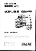
CAUTION:Cautions are used to indicate that failure to follow a procedure correctly may result in damage to the vehicle or equipment being used. NOTE:Notes are used to provide additional essential information required to carry out a complete and satisfactory repair. As you read through this manual, you will come across WARNINGS, CAUTIONS and NOTES. A warning, caution or note is placed at the beginning of a series of steps if it applies to multiple steps. If the warning, caution or note only applies to one step, it is placed at the beginning of the specific step (after the step number).
Overview Procedures Overview procedures contain an exploded view illustration(s). The numbered sequence within the illustration(s) indicate the order to be followed when removing/disassembling or when installing/assembling a component. Additional information, symbol(s) or a torque figure, may also be shown alongside the component. There are ten symbols used to give additional information when removing/disassembling or when installing/assembling a component.
1
2
3
4
5
6
7
8
9
10
Warnings, Cautions and Notes in This Manual WARNING:Warnings are used to indicate that failure to follow a procedure correctly may result in personal injury.
TIE42918
Item
Designation
Description
1
Special tool
A special tool is required for this component. There will also be a removal or installation symbol alongside the special tool symbol.
2
Install new component
Discard the old component and install a new component.
3
Inspect
Check the component for damage.
2007.50 Transit 11/2006
G935689en
General Information
100-00-4
100-00-4
DESCRIPTION AND OPERATION Item
Designation
Description
4
Apply sealant
Apply sealant to the component as specified in the materials table.
5
Apply petroleum jelly
Apply petroleum jelly to the component as specified in the materials table.
6
Apply oil
Apply oil to the component as specified in the materials table.
7
Apply fluid
Apply fluid to the component as specified in the materials table.
8
Apply grease
Apply grease to the component as specified in the mate-rials table.
9
Removal or Disassembly detail
Go to the removal or disassembly detail for additional information to remove or disassemble a component
10
Installation or Assembly detail
Go to the installation or assembly detail for additional information to install or assemble a component
Special Tools and Torque Figures
Any requirement for special tools will picture the tool, showing it in use and with its tool number shown. Torque settings will be given at the relevant point in the procedure.
59 Nm 23-045
NOTE:Removal steps in this procedure may contain installation details. Items such as O-ring seals, gaskets, seals, self-locking nuts and bolts are to be discarded and new components installed unless otherwise stated within the procedure. Coated nuts or bolts are to be reused, unless damaged or otherwise stated within the procedure. Specification procedures will contain all technical data that are not part of a repair procedure. TAS Graphics
Colors used in the graphic are as follows:
TIA2301151
Trustmark Authoring Standards (TAS) Removal and Installation Procedures NOTE:TAS style procedures can be identified by steps that have no accompanying step text and the magenta color of the electrical connectors and fasteners such as nuts, bolts, clamps or clips. A TAS removal and installation procedure uses a sequence of color illustrations to indicate the order to be followed when removing/disassembling or installing/assembling a component. Many of the TAS procedures will have the installation information within the removal steps. These procedures will have the following note at the beginning of the procedure:
2007.50 Transit 11/2006
• Blue - Indicates the target item, item to be removed/installed or disassembled/assembled • Green and Brown - Indicates a secondary item that needs to be detached, removed/installed or disassembled/assembled prior to the target item • Magenta - Indicates electrical connectors and fasteners such as nuts, bolts, clamps or clips • Pale Blue - is for the special tool(s) and general equipment There may be multiple steps assigned to one illustration. Numbered pointers are used to indicate the number of electrical connectors and fasteners such as nuts, bolts, clamps or clips. Items in the illustration can be transparent or use cutouts to show hidden detail(s).
G935689en
General Information
100-00-5
100-00-5
DESCRIPTION AND OPERATION
303-378
2
205-072
4 1
x3
3 E63828
E60043
TAS Symbols
Symbols are used inside the graphics and in the text area to enhance the information display. The following paragraphs describe the various types and categories of symbols. Prohibition symbols advise on prohibited actions to either avoid damage or health and safety related risks.
2
1
E85026
Health and Safety symbols recommend the use of particular protection equipment to avoid or at least reduce the risk or severity of possible injuries.
2007.50 Transit 11/2006
G935689en
General Information
100-00-6
100-00-6
DESCRIPTION AND OPERATION
1 2 3
E85027
Warning symbols are used to indicate potential risks resulting from a certain component or area.
E85028
2007.50 Transit 11/2006
G935689en
100-00-7
General Information
100-00-7
DESCRIPTION AND OPERATION Instruction symbols are used to apply sealer, lubricant, weight, tape or cleaning detergent to a
component.
E84834
Location symbols are used to show the location of a component or system within the vehicle.
2007.50 Transit 11/2006
G935689en
100-00-8
General Information
100-00-8
DESCRIPTION AND OPERATION
E84835
Gearshift lever or selector lever position symbols are used to show which gearshift lever or selector lever position is to be set.
2007.50 Transit 11/2006
G935689en
100-00-9
General Information
100-00-9
DESCRIPTION AND OPERATION
308-640
E84836
Pointer symbols are used to draw the attention to components and give special instructions such as a required sequence or number of components. The number of components is reflected by the value inside the luty arrow. A sequence number is
2007.50 Transit 11/2006
located inside the circle. Numbers inside circles are also used to allocate special information such as tightening torques or chemicals to a particular component.
G935689en
General Information
100-00-10
100-00-10
DESCRIPTION AND OPERATION
3 2
2 1
1
x12
E84837
Movement arrows are used to show three dimensional or rotational movements. These movements can include specific values inside the symbol if required.
2007.50 Transit 11/2006
G935689en
100-00-11
General Information
100-00-11
DESCRIPTION AND OPERATION
E84839
The following graphic illustrates a set of symbols that are used to provide detailed information on where to apply a material.
2007.50 Transit 11/2006
G935689en
100-00-12
General Information
100-00-12
DESCRIPTION AND OPERATION
E84840
Measurement symbols provide detailed information on where to carry out a specific measurement. These symbols can include specific values if required.
2007.50 Transit 11/2006
G935689en
General Information
100-00-13
100-00-13
DESCRIPTION AND OPERATION
1
2
E84841
Special Tools and Torque Figure(s)
Special tools will be shown with the tool number in the illustration. The special tool number(s), general equipment, material(s) and torque figure(s) used for the procedure step will be shown in the text column.
How to Use This Manual This manual covers diagnosis and testing, service and repair procedures. This manual is structured into groups and sections, with specific system sections collected together under their relevant group. A group covers a specific portion of the vehicle. The manual is divided into five groups, General Information, Chassis, Powertrain, Electrical and Body and Paint. The number of the group is the first number of a section number. Pages at the start of the manual list all sections available. Each section has a contents list detailing Specifications, Description and Operation, Diagnosis and Testing, In Vehicle Repairs, Disassembly and Assembly, Removal and Installation.
2007.50 Transit 11/2006
If components need to be removed or disassembled in sequence, the sequence will be identified numerically in a graphic and the corresponding text will be numbered accordingly. All left and right-hand references to the vehicle are taken from a position sitting in the driver seat looking forward. All left and right-hand references to the engine are taken from a position at the flywheel looking towards the front camshaft pulley. Where appropriate, instructions will be given for the use of the diagnostic tool. Inspection and Verification
Visual Inspection Charts, Symptom Charts and other information charts (such as diagnostic routines) or supplement test procedures with technical specifications will navigate the user to a specific test procedure. Symptom Chart
The symptom chart indicates symptoms, sources and actions to address a condition.
G935689en
100-00-14
General Information
100-00-14
DESCRIPTION AND OPERATION Pinpoint Tests
For electrical systems, pinpoint test steps are used to identify the source of a concern in a logical, step-by-step manner. pinpoint tests have two columns: CONDITIONS and DETAILS/RESULTS/ACTIONS. The CONDITIONS column is used exclusively for graphics and icons (with or without captions) and the DETAILS/RESULTS/ACTIONS column provides direction to another test step or specific corrective actions. The boxed numbers indicate the order in which the described action is to be performed. Component Tests
A component test is used when a component is tested in multiple pinpoint tests, or if a procedure is too complicated to be formatted within a single page of the pinpoint test. Graphics
Test graphics show the measurement or test to be performed in a test step. A representative tester graphic is used for voltmeters and ohmmeters. If multiple measurements are made in a single graphic, the test leads are drawn with a solid line until the test lead splits to indicate the multiple measurements, at which point dashed lines are used. Breakout box-type testers are represented by a double circle test pin. Test pins are labeled with the pin number.
2007.50 Transit 11/2006
G935689en
100-00-15
General Information
100-00-15
DESCRIPTION AND OPERATION
Health and Safety Precautions Introduction Many of the procedures associated with vehicle maintenance and repair involve physical hazards or other risks to health. This subsection lists, alphabetically, some of these hazardous operations and the materials and equipment associated with them. Precautions necessary to avoid these hazards are identified. The list is not exhaustive and all operations and procedures, and the handling of materials, should be carried out with health and safety in mind. Before using any product the Materials Safety Data Sheet supplied by the manufacturer or supplier should be consulted.
Acids and Alkalis See also Battery Acids. For example caustic soda, sulphuric acid. Used in batteries and cleaning materials. Irritant and corrosive to the skin, eyes, nose and throat. Cause burns. Can destroy ordinary protective clothing. Avoid splashes to the skin, eyes and clothing. Wear suitable protective impervious apron, gloves and goggles. Do not breath mists. Make sure access to eye wash bottles, shower and soap are readily available for splashing accidents. Display Eye Hazard sign.
Air Bags See also Fire, Chemical Materials. Highly flammable, explosive – observe No Smoking policy. Used as a safety restraint system mounted in the steering wheel and passenger side of the instrument panel. The inflator contains a high-energetic propellant which, when ignited, produces a VERY HOT GAS (2500°C). The gas generant used in air bags is Sodium Azide. This material is hermetically sealed in the module and is completely consumed during deployment. No attempt should be made to open an air bag
2007.50 Transit 11/2006
inflator as this will lead to the risk of exposure to Sodium Azide. If a gas generator is ruptured, full protective clothing should be worn when dealing with the spillage. After normal deployment, gloves and safety goggles must be worn during the handling process. Deployed air bags should be disposed of in a plastic bag in accordance with local regulations at an approved chemical waste site. Following any direct contact with gas generant. – wash affected areas thoroughly with water. – seek medical assistance if necessary. Air Bags - Do's – Do store modules in an upright position. – Do keep modules dry. – Do carry modules with the cover side pointing away from the body. – Do place modules with their cover side upwards. – Do carefully inspect modules for damage. – Do stand to one side when connecting modules. – Do make sure all test equipment is properly calibrated and maintained. – Do wash hands after handling deployed air bags. Air Bags - Do Nots – Do not store highly flammable material together with modules or gas generators. – Do not store gas generators at temperatures exceeding 80°C. – Do not store modules upside down. – Do not attempt to open a gas generator housing. – Do not expose gas generators to open flame or sources of heat. – Do not place anything on top of a module cover. – Do not use damaged modules. – Do not touch a fired module or gas generator for at least 10 minutes. – Do not use any electrical probes on the wiring circuit.
Air Conditioning Refrigerant See also Chlorofluorocarbon, Chemical Materials Highly flammable, combustible – observe No Smoking policy. G17372en
100-00-16
General Information
100-00-16
DESCRIPTION AND OPERATION Skin contact may result in frostbite. Instructions given by the manufacturer must be followed. Avoid naked lights, wear suitable protective gloves and goggles. If refrigerant comes into contact with the skin or eyes, immediately rinse the affected areas with water. Eyes should also be rinsed with an appropriate irrigation solution and should not be rubbed. SEEK MEDICAL ASSISTANCE IF NECESSARY.
Air Conditioning Refrigerant - Do Nots – Do not expose refrigerant bottles to sunlight or heat. – Do not stand refrigerant bottles upright; when filling, hold them with the valve downwards. – Do not expose refrigerant bottles to frost. – Do not drop refrigerant bottles. – Do not vent refrigerant to atmosphere under any circumstance. – Do not mix refrigerants, for example R12 (Freon) and R134a.
Adhesives and Sealers See also Fire, Chemical Materials. Highly flammable, flammable, combustible – observe No Smoking policy. Generally should be stored in No Smoking areas. Cleanliness and tidiness in use should be observed, for example disposable paper covering benches; should be dispensed from applicators where possible; containers, including secondary containers, should be labeled appropriately.
Solvent-based Adhesives/Sealers - See Solvents
Hot Melt Adhesives In the solid state, they are safe. In the molten state they may cause burns and health hazards may arise from the inhalation of toxic fumes. Use appropriate protective clothing and a thermostatically controlled heater with a thermal cut-out and adequate extraction.
Resin-based Adhesives/Sealers, for example Epoxide and Formaldehyde Resin-based Mixing should be carried out in well ventilated areas, as harmful or toxic volatile chemicals may be released. Skin contact with uncured resins and hardeners can result in irritation, dermatitis, and absorption of toxic or harmful chemicals through the skin. Splashes can damage the eyes. Provide adequate ventilation and avoid skin and eye contact.
Anaerobic, Cyanoacrylate (super-glues) and other Acrylic Adhesives Many are irritant, sensitizing or harmful to the skin and respiratory tract. Some are eye irritants. Skin and eye contact should be avoided and the manufacturers instructions followed. Cyanoacrylate adhesives (super-glues) MUST NOT contact the skin or eyes. If skin or eye tissue is bonded, cover with a clean moist pad and SEEK IMMEDIATE MEDICAL ATTENTION. Do not attempt to pull tissue apart. Use in well ventilated areas as vapors can cause irritation to the nose and eyes. For two-pack systems see Resin-based and Isocyanate Adhesives/Sealers.
Follow manufacturers instructions.
Isocyanate (Polyurethane) Adhesives/Sealers Water-based Adhesives/Sealers See also Resin-based Adhesives. Those based on polymer emulsions and rubber latexes may contain small amounts of volatile toxic and harmful chemicals. Skin and eye contact should be avoided and adequate ventilation provided during use.
2007.50 Transit 11/2006
Individuals suffering from asthma or respiratory allergies should not work with or near these materials as sensitivity reactions can occur. Over exposure is irritating to the eyes and respiratory system. Excessive concentrations may produce effects on the nervous system including G17372en
100-00-17
General Information
100-00-17
DESCRIPTION AND OPERATION drowsiness. In extreme cases, loss of consciousness may result. Long term exposure to vapor concentrations may result in adverse health effects. Prolonged contact with the skin may have a defatting effect which may lead to skin irritation and in some cases, dermatitis.
Asbestos dust waste should be dampened, placed in a sealed container and marked for safe disposal. If any cutting or drilling is attempted on materials containing asbestos the item should be dampened and only hand tools or low speed power tools used.
Battery Acids
Splashes entering the eye will cause discomfort and possible damage.
See also Acids and Alkalis.
Any spraying should preferably be carried out in exhaust ventilated booths, removing vapors and spray droplets from the breathing zone.
Gases released during charging are explosive. Never use naked flames or allow sparks near charging or recently charged batteries.
Wear appropriate gloves, eye and respiratory protection.
Make sure there is adequate ventilation.
Brake and Clutch Linings and Pads Antifreeze
See Asbestos.
See also Fire, Solvents. For example isopropanol, ethylene glycol, methanol. Highly flammable, flammable, combustible. Used in vehicle coolant systems, brake air pressure systems, screenwash solutions. Vapors may be given off from coolant antifreeze (glycol) when heated. Avoid breathing these vapors.
Brake Fluids (Polyalkylene Glycols) See also Fire. Splashes to the skin and eyes are slightly irritating. Avoid skin and eye contact as far as possible. Inhalation vapor hazards do not arise at ambient temperatures because of the very low vapor pressure.
Antifreeze may be absorbed through the skin in toxic or harmful quantities. Antifreeze, if swallowed, can be fatal and MEDICAL ATTENTION SHOULD BE SOUGHT IMMEDIATELY.
Brazing
These products must not be used in any cooling or industrial water system that is connected or linked to general, food preparation or drinking water supplies.
Chemical Materials
Asbestos See also Warning Symbols on Vehicles at the end of this subsection. Breathing asbestos dust may cause lung damage or, in some cases, cancer. Used in brake and clutch linings, transmission brake bands and gaskets. The use of drum cleaning units, vacuum cleaning or damp wiping is preferred.
2007.50 Transit 11/2006
See Welding.
See also Legal Aspects. Chemical materials such as solvents, sealers, adhesives, paints, resin foams, battery acids, antifreeze, brake fluids, fuels, oils and grease should always be used with caution and stored and handled with care. They may be toxic, harmful, corrosive, irritant or highly flammable and give rise to hazardous fumes and dusts. The effects of excessive exposure to chemicals may be immediate or delayed; briefly experienced or permanent; cumulative; superficial; life threatening; or may reduce life expectancy.
G17372en
100-00-18
General Information
100-00-18
DESCRIPTION AND OPERATION Chemical Materials - Do's – Do carefully read and observe hazard and precaution warnings given on material containers (labels) and in any accompanying leaflets, posters or other instructions. Material health and safety data sheets can be obtained from manufacturers. – Do remove chemical materials from the skin and clothing as soon as practicable after soiling. Change heavily soiled clothing and have it cleaned. – Do organize work practices and protective clothing to avoid soiling of the skin and eyes; breathing vapors, aerosols, dusts or fumes; inadequate container labeling; fire and explosion hazards. – Do wash before job breaks, before eating, smoking, drinking or using toilet facilities when handling chemical materials. – Do keep work areas clean, uncluttered and free of spills. – Do store chemical materials according to national and local regulations. – Do keep chemical materials out of the reach of children.
– Do not clean hands or clothing with chemicals. Chemicals, particularly solvents and fuels, will dry the skin and may cause irritation leading to dermatitis or be absorbed through the skin in toxic or harmful quantities. – Do not use emptied containers for other materials except when they have been cleaned under supervised conditions. – Do not sniff or smell chemical materials. Brief exposure to high concentrations of fumes can be toxic or harmful.
Chlorofluorocarbons (CFC) There is concern in the scientific community that CFCs and Halons are depleting the upper ozone layer which filters out harmful ultraviolet radiation. Decreased filtration of ultraviolet radiation may result in increases in skin cancer, cataracts and immune system suppression in humans, as well as decreased productivity of crops and aquatic systems. CFCs are used primarily as refrigerants in vehicle air conditioning systems and as aerosol propellants. Halons are used as fire extinguishants.
Clutch Fluids Chemical Materials - Do Nots See Brake fluids. – Do not mix chemical materials except under the manufacturers instructions; some chemicals can form other toxic or harmful chemicals, give off toxic or harmful fumes or become explosive when mixed together. – Do not spray chemical materials, particularly those based on solvents, in confined spaces, for example when people are inside a vehicle. – Do not apply heat or flame to chemical materials except under the manufacturers instructions. Some are highly flammable and some may release toxic or harmful fumes. – Do not leave containers open. Fumes given off can build up to toxic, harmful or explosive concentrations. Some fumes are heavier than air and will accumulate in confined areas such as pits. – Do not transfer chemical materials to unlabelled containers.
Clutch Linings and Pads See Asbestos.
Corrosion Protection Materials See also Solvents, Fire. Highly flammable, flammable – observe No Smoking policy. These materials are varied and the manufacturers instructions must be followed. They may contain solvents, resins or petroleum products. Skin and eye contact should be avoided. They should only be sprayed in conditions of adequate ventilation and not in confined spaces.
Cutting See Welding.
2007.50 Transit 11/2006
G17372en
100-00-19
General Information
100-00-19
DESCRIPTION AND OPERATION Dewaxing
Engine Oils
See Solvents and Fuels (Kerosene).
See Lubricants and Grease.
Dusts
Exhaust Fumes
Powder, dusts or clouds may be irritant, harmful or toxic. Avoid breathing dusts from powdery chemical materials or those arising from dry abrasion operations. Wear respiratory protection if ventilation is inadequate.
These contain asphyxiating, harmful and toxic chemicals and particles such as carbon oxides, nitrogen oxides, aldehydes, lead and aromatic hydrocarbons. Engines should be run only under conditions of adequate exhaust extraction or general ventilation and not in confined spaces.
Fine dusts of combustible material can present an explosion hazard. Avoid explosive limits and sources of ignition.
Electric Shock Electric shock can result from the use of faulty electrical equipment or from the misuse of equipment in good condition. Make sure that electrical equipment is maintained in good condition and frequently tested. Faulty equipment should be labeled and preferably removed from the workstation. Make sure that flexes, cables, plugs and sockets are not frayed, kinked, cut, cracked or otherwise damaged. Make sure that electrical equipment and flexes do not come into contact with water. Make sure that electrical equipment is protected by the correct rated fuse. Never misuse electrical equipment and never use equipment that is in any way faulty. The results could be fatal. Make sure that the cables of mobile electrical equipment cannot get trapped and damaged, such as in a vehicle hoist. Make sure that the designated electrical workers are trained in basic First Aid. In cases of electrocution: – switch off the power supply before approaching the victim. – if this is not possible push or drag the victim from the source of electricity using dry non-conductive material. – commence resuscitation if trained to do so. – SUMMON MEDICAL ASSISTANCE.
Gasoline (petrol) engine There may not be adequate warning of odor or of irritation before toxic or harmful effects arise. These may be immediate or delayed.
Diesel engine Soot, discomfort and irritation usually give adequate warning of hazardous fume concentrations.
Fibre Insulation See also Dusts. Used in noise and sound insulation. The fibrous nature of surfaces and cut edges can cause skin irritation. This is usually a physical and not a chemical effect. Precautions should be taken to avoid excessive skin contact through careful organization of work practices and the use of gloves.
Fire See also Welding, Foams, Legal Aspects. Many of the materials found on or associated with the repair of vehicles are highly flammable. Some give off toxic or harmful fumes if burnt. Observe strict fire safety when storing and handling flammable materials or solvents, particularly near electrical equipment or welding processes. Make sure, before using electrical or welding equipment, that there is no fire hazard present. Have a suitable fire extinguisher available when using welding or heating equipment.
2007.50 Transit 11/2006
G17372en
100-00-20
General Information
100-00-20
DESCRIPTION AND OPERATION First Aid Apart from meeting any legal requirements it is desirable for someone in the workshop to be trained in First Aid procedures. Splashes in the eye should be flushed carefully with clean water for at least ten minutes.
foams should be conducted with extraction ventilation. See also the vehicle Body Repair Manual.
Freon See Air Conditioning Refrigerant.
Soiled skin should be washed with soap and water. In case of cold burns, from alternative fuels, place affected area in cool to cold water. Individuals affected by inhalation of gases and fumes should be removed to fresh air immediately. If effects persist, consult a doctor. If liquids are swallowed inadvertently, consult a doctor giving him the information on the container or label. Do not induce vomiting unless this action is indicated on the label.
Fluoroelastomer See Viton.
Foams - Polyurethane See also Fire. Used in sound and noise insulation. Cured foams used in seat and trim cushioning. Follow manufacturers instructions. Unreacted components are irritating and may be harmful to the skin and eyes. Wear gloves and goggles. Individuals with chronic respiratory diseases, asthma, bronchial medical problems, or histories of allergic diseases should not work in or near uncured materials. The components, vapors or spray mists can cause direct irritation, sensitivity reactions and may be toxic or harmful. Vapors and spray mists must not be inhaled. These materials must be applied with adequate ventilation and respiratory protection. Do not remove the respirator immediately after spraying; wait until the vapors/mists have cleared. Burning of the uncured components and the cured foams can generate toxic and harmful fumes. Smoking, naked flames or the use of electrical equipment during foaming operations and until vapors/mists have cleared should not be allowed. Any heat cutting of cured foams or partially cured
2007.50 Transit 11/2006
Fuels See also, Fire, Legal Aspects, Chemicals and Solvents. Avoid skin contact with fuel where possible. Should contact occur, wash the affected skin with soap and water.
Gasoline (Petrol) Highly flammable - observe No Smoking policy. Swallowing can result in mouth and throat irritation and absorption from the stomach can result in drowsiness and unconsciousness. Small amounts can be fatal to children. Aspiration of liquid into the lungs, through vomiting, is a very serious hazard. Gasoline dries the skin and can cause irritation and dermatitis on prolonged or repeated contact. Liquid in the eye causes severe smarting. Motor gasoline may contain appreciable quantities of benzene, which is toxic upon inhalation, and the concentration of gasoline vapors must be kept very low. High concentrations will cause eye, nose and throat irritation, nausea, headache, depression and symptoms of drunkenness. Very high concentrations will result in rapid loss of consciousness. Make sure there is adequate ventilation when handling and using gasoline. Great care must be taken to avoid the serious consequences of inhalation in the event of vapor build up arising from spillages in confined spaces. Special precautions apply to cleaning and maintenance operations on gasoline storage tanks. Gasoline should not be used as a cleaning agent. It must not be siphoned by mouth. See First Aid.
Gas-oil (Diesel Fuel) Combustible.
G17372en
100-00-21
General Information
100-00-21
DESCRIPTION AND OPERATION Gross or prolonged skin contact with high boiling point gas oils may also cause serious skin disorders including skin cancer.
If the fuel tank is to be removed for service or repair the fuel must be evacuated using dedicated equipment and following the specified procedures.
Kerosene (Paraffin)
Gas Cylinders
Used also as heating fuel, solvent and cleaning agent.
See also Fire.
Flammable - observe No Smoking policy. Irritation of the mouth and throat may result from swallowing. The main hazard from swallowing arises if liquid aspiration into the lungs occurs. Liquid contact dries the skin and can cause irritation or dermatitis. Splashes in the eye may be slightly irritating. In normal circumstances the low volatility does not give rise to harmful vapors. Exposure to mists and vapors from kerosene at elevated temperature should be avoided (mists may arise in dewaxing). Avoid skin and eye contact and make sure there is adequate ventilation.
Alternative Fuel
Gases such as oxygen, acetylene, argon and propane are normally stored in cylinders at pressures of up to 138 bar (2000 psi) and great care should be taken in handling these cylinders to avoid mechanical damage to them or to the valve gear attached. The contents of each cylinder should be clearly identified by appropriate markings. Cylinders should be stored in well-ventilated enclosures, and protected from ice and snow, or direct sunlight. Fuel gases, for example acetylene and propane, should not be stored in close proximity to oxygen cylinders. Care should be exercised to prevent leaks from gas cylinders and lines, and to avoid sources of ignition. Only trained personnel should undertake work involving gas cylinders.
Highly flammable. Observe ``NO SMOKING" signs. Make sure there is adequate ventilation when working on alternative fuelled vehicles. Great care must be taken to avoid the serious consequences of inhalation in the event of vapor build up in confined spaces. Inhalation in high concentrations may cause dizziness, headache, nausea and loss of co-ordination. Very high concentrations may result in loss of consciousness. Contact with liquefied petroleum gas (LPG) or compressed natural gas (CNG) to the skin may cause cold burns and frost bite. Long sleeved cotton overalls, steel toe capped safety boots and rubber neoprene gloves should be worn during removal and installation of LPG/CNG fuel system components. LPG/CNG fuel leaks could cause a fire and be a hazard to health that can lead to personal injury, illness or even death. If a leak is detected, under no circumstances attempt to seal the leak by tightening the union/connection until the fuel in the system or component is depressurized. Once tightened the system should be checked for integrity following the specified procedures.
2007.50 Transit 11/2006
Gases See Gas Cylinders.
Gaskets (Fluoroelastomer) See Viton.
General Workshop Tools and Equipment It is essential that all tools and equipment are maintained in good condition and that the correct safety equipment is used where required. Never use tools or equipment for any purpose other than that for which they were designed. Never overload equipment such as hoists, jacks, axle and chassis stands or lifting slings. Damage caused by overloading is not always immediately apparent and may result in a fatal failure the next time that the equipment is used.
G17372en
100-00-22
General Information
100-00-22
DESCRIPTION AND OPERATION Do not use damaged or defective tools or equipment, particularly high-speed equipment such as grinding wheels. A damaged grinding wheel can disintegrate without warning and cause serious injury. Wear suitable eye protection when using grinding, chiseling or sand blasting equipment. Wear a suitable breathing mask when using abrasive blasting equipment, working with asbestos-based materials or using spraying equipment. Make sure there is adequate ventilation to control dusts, mists and fumes.
High Pressure Air, Lubrication and Oil Test Equipment See also Lubricants and Greases. Always keep high-pressure equipment in good condition, and regularly maintained, particularly at joints and unions. Never direct a high-pressure nozzle, for example diesel injector, at the skin as the fluid may penetrate to the underlying tissue, and cause serious injury.
Halon See CFCs.
Legal Aspects There are many laws and regulations relating to health and safety in the use and disposal of materials and equipment in a workshop. For a safe working environment and to avoid environmental pollution, workshops should be familiar, in detail, with the many health and safety laws and regulations within their country, published by both national and local authorities.
Lubricants and Greases Avoid all prolonged and repeated contact with mineral oils. All lubricants and greases may be irritating to the eyes and skin.
2007.50 Transit 11/2006
Transmission Fluids Safety instructions Certain Transmission and Power Steering fluids supplied to Ford may contain additives which have the potential to cause skin disease (dermatitis) to exposed persons. The dermatitis may be irritant or allergic in nature. Risks are higher where prolonged or repeated skin contact with a fluid may occur. These fluids are used for vehicle initial fill and service purposes. This sub-section is to: • Inform Service personnel who may come into contact with these vehicle fluids (hazard communication). • Summarise appropriate workplace control measures and personal protective equipment requirements. • Draw attention to the existence of Material Safety Datasheets (MSDS's) for the fluids (available from Ford Customer Service Division). These MSDS's contain detailed information on hazards and appropriate controls.
Control measures Workplace risk assessments made under national chemical control regulations should identify operations involving the fluids as potentially hazardous and specify workplace control and worker awareness measures. In such circumstances, the relevant Material Safety Datasheet (see the details specified below) which specifies hazards and control measures in detail should be made available for guidance. Avoid unprotected skin contact with the fluids, and in particular, avoid prolonged or repeated skin contact. Work practices should be organised so as to minimise the potential for skin contact. This may include the use of drip trays, absorbents, correct fluid handling equipment (funnels etc), and workplace housekeeping measures such as the cleaning of contaminated surfaces. Personnel engaged in operations where skin contact could occur (such as fluid draining or filling) should wear impervious gloves made from nitrile rubber, certified to a chemical protection standard, e.g. Europe Standard EN374. This glove type is widely available from reputable suppliers of gloves for chemical protection [including the manufacturers Ansell-Admont (Solvex Range), North Safety products (North Nitrile Latex Gloves range), and G17372en
100-00-23
General Information
100-00-23
DESCRIPTION AND OPERATION Marigold Industrial (Blue Nitrile range)]. If gloves become torn or contaminated on the inside they should be replaced. Eye protection with safety glasses is appropriate. Use of an impervious apron and arm protectors may be necessary if more extensive exposure is possible. Use of skin barrier creams suitable for work with mineral oil products may offer some supplementary protection, but such barrier creams should not be used in place of protective clothing. If accidental skin contact occurs with the fluids, wash the area thoroughly with soap or skin cleanser and water. Accidental eye contact should be dealt with as per normal first aid practices, by flushing the eyes with an eye wash or clean cool water for 10 minutes, after which medical attention should be obtained. Remove and launder clothing which becomes contaminated with the fluids. Do not place rags contaminated with fluid in clothing pockets. Wash thoroughly after completing operations where skin exposure may have occurred. It is important that personnel do not smoke, eat or drink whilst handling the fluids or affected transmissions. These measures are designed to limit the risk from accidental ingestion. Label any decanted fluid properly/use an equivalent label to that on original product containers. Clean up any spills promptly using an inert absorbent and wash down contaminated surfaces with detergent and water. Dispose of any waste fluids safely as hazardous waste.
Do not employ used engine oils as lubricants or for any application where appreciable skin contact is likely to occur.
Environmental Precautions Burning used engine oil in small space heaters or boilers can be recommended only for units of approved design. If in doubt check with the appropriate local authority and manufacturer of approved appliances. Dispose of used oil and used oil filters through authorized waste disposal contractors or licensed waste disposal sites, or to the waste oil reclamation trade. If in doubt, contact the relevant local authority for advice on disposal facilities. It is illegal to pour used oil on to the ground, down sewers or drains, or into watercourses.
Noise Some operations may produce high noise levels, which could, in time, damage hearing. In these cases, suitable ear protection must be worn.
Noise Insulation Materials See Foams, Fibre Insulation.
O-Rings (Fluoroelastomer) See Viton.
Paints Safety Data Sheets See also Solvents, Chemical Materials. Safety Data Sheets, which detail specific material handling instructions and precautions are available from the respective national sales company, and via internet www.msds.ford.com.
Highly flammable, flammable - observe No Smoking policy
One Pack Used Engine Oil Prolonged and repeated contact with mineral oil will result in the removal of natural fats from the skin, leading to dryness, irritation and dermatitis. In addition, used engine oil contains potentially harmful contaminants, which may cause skin cancer. Adequate means of skin protection and washing facilities must be provided.
2007.50 Transit 11/2006
Can contain harmful or toxic pigments, driers and other components as well as solvents. Spraying should be carried out only with adequate ventilation.
G17372en
100-00-24
General Information
100-00-24
DESCRIPTION AND OPERATION Two Pack Can also contain harmful and toxic unreacted resins and resin hardening agents. The manufacturers instructions should be followed. See also Resin-based Adhesives and Isocyanate Adhesives and Sealers under Adhesives and Sealers. Spraying should preferably be carried out in exhausted ventilated booths removing vapor and spray mists from the breathing zone. Individuals working in booths should wear appropriate respiratory protection. Those doing small-scale repair work in the open workshop should wear air-fed respirators.
Pressurized Equipment See High Pressure Air, Lubrication and Oil Test Equipment.
Solder Solders are mixtures of metals such that the melting point of the mixture is below that of the constituent metals (normally lead and tin). Solder application does not normally give rise to toxic lead fumes, provided a gas/air flame is used. Oxy-acetylene flames should not be used, as they are much hotter and will cause lead fumes to be produced. Some fumes may be produced by the application of any flame to surfaces coated with grease, and inhalation of these should be avoided. Removal of excess solder should be undertaken with care, to make sure that fine lead dust is not produced, which can give toxic effects if inhaled. Respiratory protection may be necessary. Solder spillage and filings should be collected and removed promptly to prevent general air contamination by lead. High standards of personal hygiene are necessary in order to avoid ingestion of lead or inhalation of solder dust from clothing.
Solvents See also Chemical Materials, Fuels (Kerosene), Fire. For example acetone, white spirit, toluene, xylene, trichloroethane.
2007.50 Transit 11/2006
Used in cleaning and dewaxing materials, paints, plastics, resins and thinners. Some may be highly flammable or flammable. Skin contact will degrease the skin and may result in irritation and dermatitis following repeated or prolonged contact. Some can be absorbed through the skin in toxic or harmful quantities. Splashes in the eye may cause severe irritation and could lead to loss of vision. Brief exposure of high concentrations of vapors or mists will cause eye and throat irritation, drowsiness, dizziness, headaches and, in the worst circumstances, unconsciousness. Repeated or prolonged exposure to excessive but lower concentrations of vapors or mists, for which there might not be adequate warning indications, can cause more serious toxic or harmful effects. Aspiration into the lungs, for example through vomiting, is the most serious consequence of swallowing. Avoid splashes to the skin, eyes and clothing. Wear protective gloves, goggles and clothing if necessary. Make sure there is good ventilation when in use, avoid breathing fumes, vapors and spray mists and keep containers tightly sealed. Do not use in confined spaces. When spraying materials containing solvents, for example paints, adhesive, coatings, use extraction ventilation or personal respiratory protection in the absence of adequate general ventilation. Do not apply heat or flame except under specific and detailed manufacturers instructions.
Sound Insulation See Fibre Insulation, Foams.
Suspended Loads CAUTION:Never improvise lifting tackle. There is always a danger when loads are lifted or suspended. Never work under an unsupported, suspended or raised load, for example a suspended engine. Always make sure that lifting equipment such as jacks, hoists, axle stands and slings are adequate and suitable for the job, in good condition and regularly maintained. G17372en
100-00-25
General Information
100-00-25
DESCRIPTION AND OPERATION Transmission Brake Bands
Welding
See Asbestos.
See also Fire, Electric Shock, Gas Cylinders.
Underseal
Welding processes include Resistance Welding (Spot Welding), Arc Welding and Gas Welding.
See Corrosion Protection.
Viton In common with many other manufacturers vehicles, some components have O-rings, seals or gaskets, which contain a material known as `Viton'. Viton is a fluoroelastomer, that is a synthetic rubber type material, which contains Fluorine. It is commonly used for O-rings, gaskets and seals of all types. Although Viton is the most well known fluoroelastomer, there are others, including Fluorel and Tecmoflon. When used under design conditions fluoroelastomers are perfectly safe. If, however, they are exposed to temperatures in excess of 400°C, the material will not burn, but will decompose, and one of the products formed is hydrofluoric acid. This acid is extremely corrosive and may be absorbed directly, through contact, into the general body system. O-rings, seals or gaskets which have been exposed to very high temperatures will appear charred or as a black sticky substance. DO NOT; under any circumstances touch them or the attached components. Enquiries should be made to determine whether Viton or any other fluoroelastomer has been used in the affected O-ring, seal or gasket. If they are of natural rubber or nitrile there is no hazard. If in doubt, be cautious, as the material may be Viton or any fluoroelastomer. If Viton or any other fluoroelastomers have been used, the affected area should be decontaminated before the commencement of work. Disposable heavy duty plastic gloves should be worn at all times, and the affected area washed down using wire wool and a limewater (calcium hydroxide) solution to neutralize the acid before disposing of the decomposed Viton residue and final cleaning of the area. After use, the plastic gloves should be discarded carefully and safely.
2007.50 Transit 11/2006
Resistance Welding This process may cause particles of molten metal to be emitted at a high velocity, and the eyes and skin must be protected.
Arc Welding This process emits a high level of ultra-violet radiation, which may cause arc-eye, and skin burns to the operator and to other persons nearby. Gas-shielded welding processes are particularly hazardous in this respect. Personal protection must be worn, and screens used to shield other people. CONTACT LENS WEARERS ARE ADVISED TO REVERT TO ORDINARY SPECTACLES WHEN ARC WELDING as the arc spectrum is believed to emit microwaves which dry out the fluid between the lens and the eye. This may result in blindness when the lens is removed from the eye. Metal spatter will also occur, and appropriate eye and skin protection is necessary. The heat of the welding arc will produce fumes and gases from the metals being welded, the rods and from any applied coatings or contamination on the surfaces being worked on. These gases and fumes may be toxic and inhalation of these should be avoided. The use of extraction ventilation to remove the fumes from the working area may be necessary particularly in cases where the general ventilation is poor, or where considerable welding work is anticipated. In extreme cases or confined spaces where adequate ventilation cannot be provided, air-fed respirators may be necessary.
Gas Welding (and Cutting) Oxy-acetylene torches may be used for welding and cutting, and special care must be taken to prevent leakage of these gases, with consequent risk of fire and explosion. The process will produce metal spatter and eye and skin protection is necessary.
G17372en
100-00-26
General Information
100-00-26
DESCRIPTION AND OPERATION The flame is bright, and eye protection should be used, but the ultra-violet emission is much less than that from arc welding, and lighter filters may be used. The process itself produces few toxic fumes, but such fumes and gases may be produced from coatings on the work, particularly during cutting away of damaged body parts, and inhalation of the fumes should be avoided. In brazing, toxic fumes may be produced from the metals in the brazing rod, and a severe hazard may arise if brazing rods containing cadmium are used. In this event particular care must be taken to avoid inhalation of fumes and expert advice may be required. SPECIAL PRECAUTIONS MUST BE TAKEN BEFORE ANY WELDING OR CUTTING TAKES PLACE ON VESSELS, WHICH HAVE CONTAINED COMBUSTIBLE MATERIALS, FOR EXAMPLE BOILING OR STEAMING OUT OF FUEL TANKS.
TIM0101002
2. Components or assemblies displaying the warning triangle with the `electrified' arrow and open book symbol give warning of inherent high voltages. Never touch these with the engine running or the ignition switched on. See Electric Shock in this subsection.
Warning Symbols on Vehicles Decals showing warning symbols will be found on various vehicle components. These decals must not be removed. The warnings are for the attention of owners/operators and persons carrying out service or repair operations on the vehicle. The most commonly found decals are reproduced below together with an explanation of the warnings.
TIM0101001
1. Components or assemblies displaying the caution triangle and open book symbol advise consultation of the relevant section of the owner literature before touching or attempting adjustments of any kind.
2007.50 Transit 11/2006
TIM0101003
3. Vehicles and replacement components which contain asbestos are identified by this symbol. See Asbestos in this subsection.
TIM0101004
4. Components or assemblies displaying this symbol give warning that the component contains a corrosive substance. See Acids and Alkalis in this subsection.
G17372en
100-00-27
General Information
100-00-27
DESCRIPTION AND OPERATION
TIM0101005
5. Displaying the caution circle with a deleted lighted match symbol, caution against the use of naked lights or flames within the immediate vicinity due to the presence of highly flammable or explosive liquids or vapors. See Fire in this subsection.
TIM0101006
6. Displaying this symbol (normally in conjunction with 5 above) warn of the presence of potentially explosive matter within the immediate vicinity.
TIM0101008
7. Displaying this symbol warn that children should not be allowed in the immediate vicinity unsupervised.
White Spirit See Solvents.
2007.50 Transit 11/2006
G17372en
100-00-28
General Information
100-00-28
DESCRIPTION AND OPERATION
Standard Workshop Practices Vehicle in Workshop When working on a vehicle in the workshop always make sure that: – the parking brake is applied or the wheels are securely chocked to prevent the vehicle moving forwards or backwards. – the key is removed from key operated hood locks before any work is carried out around the front of the vehicle. – if the engine is to be run, there is adequate ventilation, or an extraction hose to remove exhaust fumes. – there is adequate room to raise the vehicle and remove the wheels, if necessary. – fender covers are always fitted if any work is to be carried out in the engine compartment. – the battery is disconnected if working on the engine, underneath the vehicle, or if the vehicle is raised. CAUTION:When electric arc welding on a vehicle, always disconnect the generator wiring to prevent the possibility of a surge of current causing damage to the internal components of the generator. – if using welding equipment on the vehicle, a suitable fire extinguisher is readily available.
Alternative Fuel WARNING:When servicing the fuel system always follow the recommended procedures. Failure to follow these instructions may result in personal injury. If the odor of liquefied petroleum gas (LPG) or compressed natural gas (CNG) is present in the air in the workshop, warn all persons in the area to: – – – – – –
extinguish all flames and lighted tobacco. shut off electrical and air powered equipment. evacuate the area. ventilate the area. contact the fire control authorities. remove the vehicle to a dedicated, ventilated area.
2007.50 Transit 11/2006
Alternative Fuel — Do's – Do work on the vehicle in a designated area, that is well ventilated and with access restricted to qualified personnel only. – Install new warning labels to their original locations. – If possible always isolate the alternative fuel tank, and run the vehicle on the alternative fuel until it automatically switches to its normal fuel prior to taking the vehicle into the workshop service area. – Only use tested and approved components and pipes when repairing or servicing LPG and CNG systems.
Alternative Fuel — Do Nots – Do not vent off LPG fuel. – Do not use shop air pressure to force LPG fuel from the fuel tank. – Do not use paint drying ovens above 40°C for any alternative fuel vehicle. LPG and CNG fuel tanks must be removed from the vehicle prior to being put into paint drying ovens above 40°C. – Do not modify the system or install new components that are not designed for gas vehicles. – Do not evacuate fuel tanks unless there is repair that requires the removal of the fuel tank. – Do not work on the fuel lines or system components unless the alternative fuel has been evacuated and the pressure in the system reduced to atmospheric or less. – Do not use anything other than the specified leak detector fluid to trace fuel leaks. Be aware of situations that may cause the LPG or CNG fuel system to vent off fuel, such as: – extremely hot days. – parking by a space heater. – hoisting a vehicle up near a ceiling heater. Only fully trained personnel, who are conversant with local standards, are to work on alternative fuel vehicles.
G17373en
100-00-29
General Information
100-00-29
DESCRIPTION AND OPERATION Towing the Vehicle WARNING:When the vehicle is being towed, the ignition switch must be in position II (steering lock released and warning lamps illuminated). Only then will the steering, turn signal lamps, horn and stop lamps be operational. Failure to follow these instructions may result in personal injury. NOTE:The removable towing eye (if equipped), has a left-hand thread and must be fully tightened before towing can commence.
an instance, the discharged battery must be recharged immediately after jump starting to avoid permanent damage. – Always make sure that the jumper cables are adequate for the task. Heavy duty cables must be used. – Always make sure that the slave battery is of the same voltage as the vehicle battery. The batteries must be connected in parallel. – Always make sure that switched electric circuits are switched off before connecting jumper cables. This reduces the risk of arcing occurring when the final connection is made.
When towing is necessary, the vehicle towing eyes should be used. The rope must be securely fastened to the towing eyes and must also be attached to the other vehicle such that the rope will not foul the bodywork. When a vehicle with automatic transmission is towed, the gear selector must be in position N (Neutral). Never tow a vehicle with automatic transmission at a speed greater than 30 mph (50 km/h) or for a distance greater than 30 miles (50 km). If it is necessary to tow the vehicle a greater distance, the drive wheels must be lifted clear off the ground. Alternatively the vehicle can be transported on a low loader or a trailer.
Connecting a Slave Battery Using Jumper Cables WARNING:If the slave battery has recently been charged and is gassing, cover the vent plugs or covers with a damp cloth to reduce the risk of explosion should arcing occur when connecting the jumper cables. Failure to follow these instructions may result in personal injury. CAUTIONS: A discharged battery condition may have been caused by an electrical short circuit. If this condition exists there will be an apparently live circuit on the vehicle even when all normal circuits are switched off. This can cause arcing when the jumper cables are connected. While it is not recommended that the vehicle is jump started, it is recognized that this may occasionally be the only practical way to mobilize a vehicle. In such
2007.50 Transit 11/2006
TIM0103001
WARNING:Make sure that the ends of the jumper cables do not touch each other or ground against the vehicle body at any time while the cables are attached to the battery. A fully charged battery, if shorted through jumper cables, can discharge at a rate well above 1000 amps causing violent arcing and very rapid heating of the jumper cables and terminals, and can even cause the battery to explode. Failure to follow these instructions may result in personal injury. Always connect the jumper cables in the following sequence: – Slave battery positive first and then vehicle battery positive. – Slave battery negative next and then vehicle ground at least 12 inches (300 mm) from the battery terminal, for example engine lifting eye. Always reduce the engine speed to idle before disconnecting the jumper cables. Before removing the jumper cables from the vehicle that had the discharged battery, switch on the heater blower (high) or the heated rear window, to reduce the voltage peak when the cables are removed.
G17373en
100-00-30
General Information
100-00-30
DESCRIPTION AND OPERATION Always disconnect the jumper cables in the reverse order to the connecting sequence and do not short the ends of the cables. Do not rely on the generator to restore a discharged battery. For a generator to recharge a battery, it would take in excess of eight hours continuous driving with no additional loads placed on the battery.
Component Cleaning To prevent the ingress of dirt, accumulations of loose dirt and greasy deposits should be removed before disconnecting or dismantling components or assemblies. Components should be thoroughly cleaned before inspection prior to reassembly.
Cleaning Methods: – – – –
Dry cleaning. Removal of loose dirt with soft or cable brushes. Scraping dirt off with a piece of metal or wood. Wiping off with a rag.
Various solvents are available which are suitable for component cleaning. Some components, such as brake hydraulic parts and electrical assemblies should be cleaned only with recommended solvents — refer to Solvents, Sealers and Adhesives or to the section of the manual relevant to the component.
Calibration of Essential Measuring Equipment WARNING:Equipment, which requires regular calibration, must be calibrated in accordance with the manufacturers instructions. Failure to follow this instruction may result in personal injury or damage to components. It is of fundamental importance that certain essential equipment, for example torque wrenches, multimeters, exhaust gas analyzers or rolling roads, are regularly calibrated in accordance with the manufacturers instructions.
WARNING:Wear eye protection when cleaning vehicle components with compressed air, a steam cleaner or a power washer. Failure to follow this instruction may result in personal injury. CAUTIONS: Compressed air is sometimes 'wet' so use with caution, especially on hydraulic systems. To prevent damage to the electrical connectors in the engine compartment, do not use a steam cleaner or a power washer to clean the engine compartment. – Blowing dirt off with compressed air. – Removal of dry dust using vacuum equipment. This method must always be used to remove friction lining material dust (asbestos particles). – Steam cleaning. WARNING:Most solvents require careful handling and some are harmful. Refer to Health and Safety Precautions and to the manufacturers literature for the relevant safety precautions. Failure to follow these instructions may result in personal injury.
2007.50 Transit 11/2006
G17373en
100-00-31
General Information
100-00-31
DESCRIPTION AND OPERATION
Solvents, Sealants and Adhesives Introduction WARNING:Always handle all solvents, sealers and adhesives with extreme care. Some contain chemicals or give off fumes which can be dangerous to health. Always follow the manufacturers instructions. If in doubt about any substance, particularly a solvent, DO NOT use it. CAUTION:If in doubt about the suitability of any proprietary solvent or sealer for a particular application, contact the manufacturer of the product for information regarding storage, handling and application. The Health and Safety Precautions subsection refers to some commonly used chemicals and materials, hazards associated with their use, and safety measures to be taken.
2007.50 Transit 11/2006
G17374en
100-00-32
General Information
100-00-32
DESCRIPTION AND OPERATION
Road/Roller Testing Road or roller testing may be carried out for various reasons and a procedure detailing pre-test checks, engine starting and stopping, pre-driving checks, on-test checks and final checks to be completed on completion of the test is given below. Unless complete vehicle performance is being checked, the full road test procedure need not be carried out. Instead, those items particularly relevant to the system(s) being checked can be extracted.
Pre-Test Checks WARNING:If the brake system hydraulic fluid level is low, pedal travel is excessive or a hydraulic leak is found, do not attempt to road test the vehicle until the reason for the low fluid level, excessive pedal travel or hydraulic leak is found and rectified. It is suggested that pre-test checks and functional tests of those systems and circuits which affect the safe and legal operations of the vehicle, such as brakes, lights and steering, should always be carried out before the road or roller test.
– that the parking brake is applied. – that the gear lever is in the neutral position. – that all instrument gauges (except fuel gauge) read zero. With the ignition switched on, check: – that the ignition controlled warning lamps are illuminated. – that the engine temperature gauge registers a reading compatible with the engine temperature. – that the fuel gauge registers a reading appropriate to the fuel level in the tank. – the operation of the parking brake warning lamp and fluid level warning indicator.
Road or Roller Testing CAUTION:If road testing, check the brake operation while still traveling at low speed before continuing with the test. If the brakes pull to one side, or appear to be otherwise faulty, do not continue with the road test until the fault has been found and rectified.
With the ignition switched off, check:
During the road or roller test, check:
– the engine oil level. – the engine coolant level. – the tires, for correct pressure, compatible types and tread patterns, and wear within limits. – that there is sufficient fuel in the tank to complete the test. – all around the engine, transmission and under the vehicle for oil, coolant, hydraulic and fuel leaks. Make a note of any apparent leaks and wipe off the surrounding areas to make it easier to identify the extent of the leak on completion of the test.
– that the clutch pedal operation is not stiff or heavy. – that the initial gear engagement is smooth and there is no evidence of clutch drag. – that the parking brake control operates smoothly and releases quickly and completely. – that the clutch takes up the drive smoothly, without slip or judder. – that gear changing is smooth with no abnormal noises or vibrations from the transmission. – the engine power output is satisfactory, full power is achieved, acceleration is smooth and pedal operation is not stiff or heavy, and engine speed returns to idle correctly. – there is no excessive or abnormally colored smoke from the engine under normal driving, heavy load or overrun conditions. – that steering operation, including power steering (if equipped), is smooth, accurate, not excessively heavy or with excessive free play or vibration. – that the steering does not pull to one side and self centers smoothly after cornering.
Starting the Engine NOTE:On initial drive away from cold and within the first 1.5 km (1 mile), do not depress the accelerator pedal beyond half travel until the vehicle has attained a minimum speed of 25 km/h (15 miles/h). Never operate at high engine speed or with the accelerator pedal at full travel whilst the engine is cold. With the ignition switched off, check:
2007.50 Transit 11/2006
G17375en
100-00-33
General Information
100-00-33
DESCRIPTION AND OPERATION – that the speedometer, coolant temperature gauge and tachometer (if equipped) register the correct readings and operate correctly. – that the switches and controls operate smoothly and positively, warning and indicator lamps operate correctly and the direction indicator control self cancels when the steering is returned to the straight ahead position. – that the heating and ventilation systems operate correctly and effectively. – the brake operation and efficiency.
– oil, coolant, hydraulic, air and fuel leaks. – abnormal temperature of any moving components or assemblies, for example wheel hubs, transmission and axle, which might indicate over tightness or lack of lubrication.
Brake Testing WARNING:When brake testing, avoid breathing the fumes from hot brakes, this may contain asbestos dust which is hazardous to health. Failure to follow this instruction may result in personal injury. For additional information, refer to:Health and Safety Precautions (100-00 General Information, Description and Operation). CAUTIONS: Avoid brake testing on busy roads where it may cause inconvenience or danger to other road users. Brake testing which includes heavy brake applications should not be carried out with new brake pads/discs or linings/drums until the components have bedded-in. New brake friction components will not reach full efficiency until the bedding-in process is complete. Test the brakes at several speeds within the normal operating range using both light and heavy pedal pressure. Note any tendency to snatch, pull or drag, and any undue delay in application or release. Allow the vehicle to coast and note any tendency to pull to one side, or evidence that the brakes are binding. After stopping the vehicle (not immediately after a period of heavy braking), carefully check the brake temperature. A brake disc or brake drum that feels hot or is appreciably hotter than the others, indicates that the brake is binding. After completion of the test, check for:
2007.50 Transit 11/2006
G17375en
100-00-34
General Information
100-00-34
DESCRIPTION AND OPERATION
Battery and Battery Charging Health and Safety Precautions WARNINGS: Batteries contain sulphuric acid, avoid contact with skin, eyes or clothing. Wear safety goggles when working near the battery to protect against possible splashing of the acid solution. In cases of acid contact with the skin or eyes, flush immediately with water for a minimum of 15 minutes and seek prompt medical attention. If swallowed, seek immediate medical attention. Batteries normally produce explosive gases. Do not allow naked flames, sparks or lighted substances to come near the battery. When charging the battery shield your face and wear safety goggles. Provide adequate ventilation. CAUTION:Boost charging with excessive current or voltage above 16 volts will damage the battery.
2007.50 Transit 11/2006
G548994en
100-00-35
General Information
100-00-35
DESCRIPTION AND OPERATION
Engine Cooling System Health and Safety Precautions WARNINGS: Extreme care must be exercised when handling hot fluids. Always wash off spilled fluids from exposed skin immediately. Vapors may be given off from antifreeze when heated. Avoid breathing these vapors. Antifreeze may be absorbed through the skin in toxic or harmful quantities. If taken internally, drink water and induce vomiting. Seek medical attention immediately. Antifreeze must not be used in any cooling or industrial water system that is connected or linked to general water supplies.
2007.50 Transit 11/2006
G548995en
100-00-36
General Information
100-00-36
DESCRIPTION AND OPERATION
Petrol Fuel System Health and Safety Precautions WARNINGS: Extreme care must be exercised when handling hot fluids. Always wash off spilled fluids from exposed skin immediately. Highly flammable mixtures are always present and may ignite when working on fuel systems. Do not allow naked flames, sparks or lighted substances to come near fuel related components. There may not be adequate warning of odor or of irritation before toxic or harmful effects arise. These may be immediate or delayed.
CAUTIONS: Fuel injection equipment is manufactured to very precise tolerances and fine clearances. It is essential that absolute cleanliness is observed when working with these components. Make sure that the workshop area in which the vehicle is being worked on is as clean and as dust free as possible.
Swallowing can result in mouth and throat irritation and absorption from the stomach can result in drowsiness and unconsciousness. Small amounts can be fatal to children. Aspiration of liquid into the lungs, through vomiting, is a very serious hazard. Gasoline dries the skin and can cause irritation and dermatitis on prolonged or repeated contact. Liquid in the eye causes severe smarting. Motor gasoline may contain appreciable quantities of benzene, which is toxic upon inhalation, and the concentration of gasoline vapors must be kept very low. High concentrations will cause eye, nose and throat irritation, nausea, headache, depression and symptoms of drunkenness. Very high concentrations will result in rapid loss of consciousness. Make sure there is adequate ventilation when handling and using gasoline. Great care must be taken to avoid the serious consequences of inhalation in the event of vapor build up arising from spillages in confined spaces. Special procedures apply to cleaning and maintenance operations on gasoline storage tanks. Gasoline should not be used as a cleaning agent. It must not be siphoned by mouth. See First Aid.
2007.50 Transit 11/2006
G548996en
100-00-37
General Information
100-00-37
DESCRIPTION AND OPERATION
Diesel Fuel System Health and Safety Precautions WARNINGS: Extreme care must be exercised when handling hot fluids. Always wash off spilled fluids from exposed skin immediately. Combustible. Gross or prolonged skin contact with high boiling point gas oils may also cause serious skin disorders including skin cancer. CAUTIONS: Fuel injection equipment is manufactured to very precise tolerances and fine clearances. It is essential that absolute cleanliness is observed when working with these components. Make sure that the workshop area in which the vehicle is being worked on is as clean and as dust free as possible. NOTE:Soot, discomfort and irritation usually give adequate warning of hazardous fume concentrations.
2007.50 Transit 11/2006
G548997en
100-00-38
General Information
100-00-38
DESCRIPTION AND OPERATION
Air Conditioning (A/C) System Health and Safety Precautions WARNINGS: Only qualified technicians are allowed to work on air conditioning (A/C) systems. Air conditioning (A/C) system components can become particularly hot or cold. When handling refrigerants, always wear protective goggles and gloves made of fluoroelastomer. Leather or fabric gloves are not suitable. Make sure that the air conditioning (A/C) system is at ambient temperature before carrying out any repair. If liquid refrigerant comes into contact with the skin, it produces severe frostbite. Immediately rinse the affected areas with water for 15 minutes. Seek medical attention. If refrigerant comes into contact with the eyes, immediately rinse the eyes with plenty of water for 15 minutes. Seek medical attention. If refrigerant comes into contact with naked flames or hot surfaces, it produces toxic gases (fluorine and phosgene). The toxic gases formed are readily recognizable by their pungent smell at tiny concentrations. Refrigerant is flammable and explosive. Make sure that the local regulations regarding work on air conditioning (A/C) systems are adhered to. Make sure that refrigerant bottles are not exposed to temperatures greater than 45°C. Make sure that refrigerant bottles are closed properly. Toxic gases generated when refrigerant is heated are hazardous to health. The gases have an irritating smell and can cause lung damage. The symptoms can continue for a long time after having been in contact with the gases. The gases can cause lung damage even if the amount of gas in the air is too small to smell. Gaseous refrigerant has a higher density than air. There is a danger of suffocation when working close to the ground or in workshop pits.
2007.50 Transit 11/2006
Provide adequate ventilation when handling refrigerant. Never release refrigerant into the atmosphere. Only use special tools, equipment and lubricants that are approved for the type of refrigerant being used. The pressurized container in the servicing unit must never be over-filled. The refrigerant must have sufficient room to expand if the temperature rises. Always follow the manufacturer’s instructions for the correct servicing unit operating procedure. CAUTIONS: Do not mix refrigerant oils for different types of refrigerant. Never mix different types of refrigerant or equipment intended for them. Only use refrigerant in gas form when filling the system through the low-pressure connection. Only use refrigerant in liquid form when filling the system through the high-pressure connection. Refrigerant attacks certain plastics. Only use seals suitable for refrigerant. If the air conditioning (A/C) compressor is damaged, the fixed orifice tube can become blocked with metal particles. Any sort of blockage in the refrigerant circuit will damage the air conditioning (A/C) compressor irreparably. If the air conditioning (A/C) system has been opened for a period greater than 2 hours, a new receiver drier must be installed and the evacuating time to be increased by a minimum of 2 hours. NOTE:New air conditioning (A/C) compressors are delivered prefilled. NOTE:Refrigerant oil in new air conditioning (A/C) compressors can contain Teflon, visible as white particles, which will not harm the system.
G548993en
100-00-39
General Information
100-00-39
DESCRIPTION AND OPERATION
Supplemental Restraint System (SRS) Health and Safety Precautions WARNINGS: Undeployed pyrotechnic supplemental restraint system (SRS) components must not be deployed in the vehicle. Never carry out any electrical measurement on disconnected, undeployed supplemental restraint system (SRS) pyrotechnic components. Pyrotechnic components must not be disassembled. Pyrotechnic components are not interchangeable between vehicles. Always carry a live air bag module away from the body with the air bag or trim cover pointing upwards. Live air bag modules must be placed in a suitable cage when removed from the vehicle. The air bag or trim cover must be facing upwards. CAUTIONS: Supplemental restraint system (SRS) components must not be subjected to temperatures higher than 110°C. Never install aftermarket accessories to the vehicle on or adjacent to the supplemental restraint system (SRS) module.
2007.50 Transit 11/2006
G548998en
100-00-40
General Information
100-00-40
DESCRIPTION AND OPERATION
Brake System Health and Safety Precautions WARNING:Brake fluid contains polyglycol ethers and polyglycols. Avoid contact with the eyes. Wash hands thoroughly after handling. If brake fluid comes into contact with the eyes, flush the eyes with cold running water for 15 minutes. Seek medical attention if irritation persists. If taken internally, drink water and induce vomiting. Seek medical attention immediately. CAUTION:If brake fluid is spilled on the paintwork, the affected area must be immediately washed down with cold water.
2007.50 Transit 11/2006
G565862en
100-01-1
Identification Codes
100-01-1
.
SECTION 100-01 Identification Codes VEHICLE APPLICATION:2007.50 Transit CONTENTS
PAGE
DESCRIPTION AND OPERATION Identification Codes............................................................................................................ Vehicle Identification Number......................................................................................... Vehicle Certification Label (Typical) or VIN Plate...............................................................
100-01-2 100-01-3 100-01-6
Identification Codes
100-01-2
100-01-2
DESCRIPTION AND OPERATION
Identification Codes NOTE:The vehicle identification number (VIN) can be identified by an asterisk (*) at its start and finish.
The VIN is also stamped on the VIN plate. The VIN plate is located on the passenger side B-pillar.
The VIN for registration purposes is stamped onto the body on the front right-hand side wheel arch.
The visible VIN (label) is located on the instrument panel close to the windshield glass on the left-hand side of the vehicle and is visible from the outside.
2
1 E73666
Item 1 Visible VIN 2
Description
VIN plate
2007.50 Transit 11/2006
G834583en
Identification Codes
100-01-3
100-01-3
DESCRIPTION AND OPERATION Vehicle Identification Number
1
2
3
4
5
6
7
8
4
9 10
11
2
E0013277
Item Description 1 VIN Position 1 — Not Used
Item Description 8 VIN Position 11 — Model range
2
VIN Position 2 and 20 — Constant *
9
VIN Position 13 — Year of Manufacture
3
VIN Position 3, 4 and 5 — World Manufacturer Identifier
10
VIN Position 14 — Month of Manufacture
11
VIN Position 15-19 — Vehicle Sequence Number
4
VIN Position 6 and 12 — Model Variant
5
VIN Position 7 and 8 — Constant XX
Item 1 - VIN Position 1
6
VIN Position 9 — Product Source Company
Not used.
7
VIN Position 10 — Assembly Plant
Item 2 - VIN Positions 2 and 20
Constant *. Item 3 - VIN Position 3, 4 and 5 — World Manufacturer Identifier Code World Manufacturer WF0 Item 4 - VIN Position 6 and 12 — Model Variant Code
Ford Werke AG Germany
Model Variant
B
Bus (M1)
D
Bus (M2)
2007.50 Transit 11/2006
G834583en
Identification Codes
100-01-4
100-01-4
DESCRIPTION AND OPERATION Code
Model Variant
F
Chassis single cab
N
Chassis double cab
S
Kombi (M1)
X
Van
Z
Kombi Van — (M1)
1
Kombi (N1) — Turkey only
3
Kombi Van (N1) — Turkey only
Item 5 - VIN Positions 7 and 8
Constant X. Item 6 - VIN Positions 9 — Product Source Company Code Product Source Company B
Ford of Britain own assembly
C
Ford of Britain affiliated company assembly
D
Ford of Britain dealer assembly
E
Ford of Germany affiliated company assembly
F
Ford of Germany dealer assembly
G
Ford of Germany own assembly
H
Knock down assembly
T
Turkey
Item 7 - VIN Position 10 — Assembly Plant Code
Assembly Plant
B
Genk
D
Southampton
G
Poland
J
Istanbul
P
Portugal
T
Izmit
Item 8 - VIN Position 11 — Model Range Code F
Model Range Transit
Item 9 - VIN Position 13 — Year of Manufacture Code Year of Manufacture 6
2006
7
2007
2007.50 Transit 11/2006
G834583en
Identification Codes
100-01-5
100-01-5
DESCRIPTION AND OPERATION Code
Year of Manufacture
8
2008
9
2009
A
2010
Item 10 - VIN Position 14 — Month of Manufacture Month 2006 2007
2008
2009
2010
January
L
C
B
J
L
February
Y
K
R
U
Y
March
S
D
A
M
S
April
T
E
G
P
T
May
J
L
C
B
J
June
U
Y
K
R
U
July
M
S
D
A
M
August
P
T
E
G
P
September
B
J
L
C
B
October
R
U
Y
K
R
November
A
M
S
D
A
December
G
P
T
E
G
Item 11 - VIN Position 15 to 19 — Vehicle Sequence Number
Five digit number.
2007.50 Transit 11/2006
G834583en
Identification Codes
100-01-6
100-01-6
DESCRIPTION AND OPERATION Vehicle Certification Label (Typical) or VIN Plate
21
1
2
3
4
20 19 18 5
17 16
6
15 14 13
7
12
11
10
9
8
TIE0013276
Item 1 2
Part Description Number Type approval code -
Item 15
Part Description Number Hand of drive
Vehicle identification number (VIN)
16
-
Body color codes
17
-
Brakes
3
-
Gross vehicle mass (GVM)
18
-
Interior trim codes
4
-
Gross train mass (GTM)
19
-
Smoke values
5
-
Maximum permissible front axle mass
20
-
Engine type codes
6
-
Maximum permissible rear axle mass
7
-
Vehicle dimensions
Item 1: Type Approval Code
8
-
Model type codes
9
-
Wheelbase
A unique code required by legislation in certain territories.
10
-
Rear axle/axle ratio
11
-
Used by SVO only
Item 2: Vehicle Identification Number (VIN)
12
-
Transmission identification
Vehicle identification number.
13
-
Door combination
14
-
Suspension
2007.50 Transit 11/2006
21
Blank
G834583en
Identification Codes
100-01-7
100-01-7
DESCRIPTION AND OPERATION Item 3: Gross Vehicle Mass
Item 6: Maximum Permissible Rear Axle Mass
Indicates maximum legal laden mass, in territories where this is required.
Maximum permissible loading on the rear wheels of the vehicle.
Item 4: Gross Train Mass Item 7: Vehicle Dimensions Indicates the maximum combined mass of vehicle and trailer or caravan.
Item 5: Maximum Permissible Front Axle Mass
Dimensions of the vehicle in mm.
Item 8: Model Type Codes Model type code usage.
Maximum permissible loading on the front wheels of the vehicle. Digit 1 - Vehicle Digit 1 F Digit 2 - Body Digit 2
Vehicle Transit
Body
A
Van (N1/N2)
B
Passenger car (Bus M1)
C
Bus (M2)
D
Passenger car (Kombi M1)
M
Chassis single cab (N1/N2)
N
Chassis double cab (N1/N2)
S
Passenger car (Kombi van M1)
Z
Passenger car (Kombi special M1)
Digit 3 - Wheelbase/Drive Digit 3
Wheelbase/Drive
A
Short wheelbase 2933/3137 mm rear wheel drive
B
Medium wheelbase 3300/3504 mm rear wheel drive
C
Long wheelbase 3750/3954 mm rear wheel drive
D
Long wheelbase 3750/3954 mm rear wheel drive extended frame
E
Short wheelbase 2933/3137 mm front wheel drive
F
Medium wheelbase 3300/3504 mm front wheel drive
G
Long wheelbase 3750/3954 mm front wheel drive
H
Long wheelbase 3750/3954 mm front wheel drive extended frame
2007.50 Transit 11/2006
G834583en
Identification Codes
100-01-8
100-01-8
DESCRIPTION AND OPERATION Digit 4 - Model Year Digit 4
Model Year
6
2006.5
Digits 5 to 8 - Engine Variant Digits 5 to 8
Engine variant
GZFA
Engine code north - south
GZFB
Engine code north - south
HFFA
Engine code north - south
H9FB
Engine code north - south
JXFA
Engine code north - south
PHFA
Engine code north - south
P8FA
Engine code east - west
QVFA
Engine code east - west
QWFA
Engine code east - west
QWFB
Engine code east - west
RBFA
Engine code north - south
RCFA
Engine code north - south
Digit 9 - Steered Axle Digit 9
Steered axle
1
-
2
-
Digit 10
Not used. Digit 11 - Variant and Digit 17 - Gross Vehicle Mass in Kg Digit 11
Digit 17
A
B
C
D
A
260 Short wheelbase
2600
2400
2000
2350
B
280 Short wheelbase
2800
2500
3000
–
C
300 Short wheelbase
3000
–
–
–
D
330 Medium wheelbase
3300
–
–
–
E
350 Medium wheelbase Single rear wheel
3500
3550
3490
3850
F
350 Medium wheelbase Twin rear wheel
3500
3550
3490
3850
G
430 Medium wheelbase Twin rear wheel
4250
3490
3550
4100
2007.50 Transit 11/2006
G834583en
Identification Codes
100-01-9
100-01-9
DESCRIPTION AND OPERATION Digit 11
Digit 17 A
B
C
D
H
350 Long wheelbase Single rear wheel, High front axle
3500
3550
3490
3850
J
350 Long wheelbase Twin rear wheel, High front axle
3500
3550
3490
3850
K
430 Long wheelbase Twin rear wheel, High front axle
4250
3490
3550
4100
L
350 Long wheelbase Single rear wheel, High rear axle
3500
3550
3490
3850
M
350 Long wheelbase Twin rear wheel, High front axle, High rear axle
3500
3550
3490
3850
Digit 11 - Variant and Digit 17 - Gross Vehicle Mass in Kg (continued) Digit 10 Digit 11 E
F
G
H
J
A
260 Short wheelbase
2500
–
–
–
–
B
280 Short wheelbase
–
–
–
–
–
C
300 Short wheelbase
–
–
–
–
–
D
330 Short wheelbase
–
–
–
–
–
E
350 Medium wheelbase Single rear wheel
–
–
–
–
–
F
350 Medium wheelbase Twin rear wheel
–
–
–
–
–
G
430 Medium wheelbase Twin rear wheel
3500
3850
–
–
–
H
350 Long wheelbase Single rear wheel, High front axle
–
–
–
–
–
J
350 Long wheelbase Twin rear wheel, High front axle
–
–
–
–
–
K
430 Long wheelbase Twin rear wheel, High front axle
3500
3850
–
–
–
L
350 Long wheelbase Single rear wheel, High rear axle
–
–
–
–
–
M
350 Long wheelbase Twin rear wheel, High front axle, High rear axle
–
–
–
–
–
Digit 12 - Seats Digit 12
Description
1–9
Maximum number of seats M1/N1/M2/N2 vehicles
A
11 seats maximum M2 vehicles
2007.50 Transit 11/2006
G834583en
100-01-10
Identification Codes
100-01-10
DESCRIPTION AND OPERATION Digit 12
Description
B
12 seats maximum M2 vehicles
C
13 seats maximum M2 vehicles
D
14 seats maximum M2 vehicles
E
15 seats maximum M2 vehicles
F
16 seats maximum M2 vehicles
G
18 seats maximum M2 vehicles
Digit 13 - Transmission Digit 13
Description
A
5-speed manual transmission (VXT75)
B
5-speed manual transmission (MT75)
C
6-Speed Manual Transmission (MT82)
Digit 14 - Final Drive Digit 14
Ratio
A
4.23
B
4.54
C
3.73
D
4.27
E
4.78
F
5.11
G
5.44
H
5.88
J
4.23 with reduced GTM
K
4.54 with reduced GTM
L
3.73 with reduced GTM
M
4.27 with reduced GTM
Digit 15
Digit 16
Not used.
Not used.
Item 9: Wheelbase Wheelbase Measured in mm
2007.50 Transit 11/2006
G834583en
Identification Codes
100-01-11
100-01-11
DESCRIPTION AND OPERATION Item 10: Rear Axle/Axle Ratio Code
Ratio
A
T51 /5.44 rear wheel drive
B
T51 /5.88 rear wheel drive
C
T53 /3.73 rear wheel drive
D
T53 4.27 rear wheel drive
E
T53/4.78 rear wheel drive
F
T53/5.11 rear wheel drive
G
T53/5.44 rear wheel drive
H
T53 /5.88 rear wheel drive
T
4.23 front wheel drive
U
4.54 front wheel drive
W
T51 /3.73 rear wheel drive
X
T51 /4.27 rear wheel drive
Y
T51 /4.78 rear wheel drive
Z
T51 /5.11 rear wheel drive
Item 11 Used by SVO only.
Item 12: Transmission/Transaxle Identification Code
Transmission
M6
6-speed manual transmission (MT82) (5.44)
V2
5-speed manual transmission (VXT75) (3.80)
W2
5-speed manual transmission (MT75) (4.20)
Item 13: Door Combination Cod e
Roof
Front Doors Hinged
Low Mid High
LH sliding
A
x
x
B
x
x
C
x
2007.50 Transit 11/2006
Side Loading Doors
RH sliding
RH sliding LH sliding
x
G834583en
Identification Codes
100-01-12
100-01-12
DESCRIPTION AND OPERATION Cod e
Roof
Front Doors Hinged
Low Mid High
Side Loading Doors
LH sliding
D
x
x
x
E
x
x
x
x
x
F
x
RH sliding
G
x
x
x
H
x
x
x
x
x
J
x
RH sliding LH sliding
K
x
x
x
L
x
x
x
x
x
M
x
N
x
x
P
x
x
Q
x
x
x x x
Item 13: Door Combination (continued) Code Double Hinged Low A
Rear Loading Doors
Double Hinged Medium
x
C
x x
E
x
F G
x x
H
x
J K
Double Hinged High
x
B
D
Tailgate
x x
L M
x x
N
x
P
x
Q
x
2007.50 Transit 11/2006
G834583en
Identification Codes
100-01-13
100-01-13
DESCRIPTION AND OPERATION Item 14: Suspension Code
Rear Springs and Shock Absorber
AA
Standard
1L
Heavy duty suspension
B1
Soft ride suspension
03
High center of gravity vehicle
B3
Soft ride suspension and high center of gravity vehicle
Item 15: Hand of Drive Code
Drive
L
Left-hand drive
R
Right-hand drive
Item 16: Body Color Codes Code
Body Color
BD
Safron yellow
EC
Pepper red
KD
Dark blue
KL
Dark true blue
ND
Colorado red
PC
Jewel green
UM
Magnum grey
ZJ
Moondust silver
3B
Tonic
3D
Blue ambition
-
Frozen white
-
Sublime
Item 17: Brakes Code
Brake System
B
Booster with dual line diagonal split brake system, with anti-lock brakes (ABS)
C
Booster with dual line diagonal split brake system, without anti-lock brakes (ABS), with rear drum
H
Booster with dual line diagonal split brake system, without anti-lock brakes (ABS)
2007.50 Transit 11/2006
G834583en
Identification Codes
100-01-14
100-01-14
DESCRIPTION AND OPERATION Item 18: Interior Trim Code
Seat Trim
Description
Door trim
Color
5KA
York weave
Low back individual passenger
Cordwain
Lichen
5KB
Tomy woven
Low back individual passenger
Cordwain
Lichen
5KC
York weave
Low back dual passenger
Cordwain
Lichen
5KD
Tomy woven
Low back dual passenger
Cordwain
Lichen
5MD
Velour
Low back individual passenger
Cordwain
Lichen
5ME
Velour
Low back dual passenger
Cordwain
Lichen
5MF
Leather
Low back individual passenger
Cordwain
Lichen
5MG
Leather
Low back dual passenger
Cordwain
Lichen
Item 19: Smoke Values Smoke Value
Engine Code
Engine
Emissions
1.31
P8FA
2.2L 85PS
Stage IV
1.44
QVFA
2.2L 110PS
Stage IV
1.64
QWFA
2.2L 130PS
Stage IV
1.62
PHFA
2.4L 100PS
Stage IV
1.56
JXFA
2.4L 115PS
Stage IV
1.49
H9FB
2.4L 140PS
Stage IV
Item 20: Engine Type Codes Code
Engine
Catalytic Converter
kW
Transmission / Transaxle
Emission
GZFA
2.3L 146PS
Y
107
M
Stage IV
GZFB
2.3L 146PS
Y
107
M
Stage III
HFFA
2.4L 120PS
N
88
M
Stage I
H9FB
2.4L 140PS
Y
103
M
Stage IV
JXFA
2.4L 115PS
Y
85
M
Stage IV
PHFA
2.4L 100PS
Y
74
M
Stage IV
P8FA
2.2L 85PS
Y
63
M
Stage IV
QVFA
2.2L 150PS
Y
81
M
Stage IV
QWFA
2.2L 130PS
Y
96
M
Stage IV
QWFB
2.2L 130PS
N
96
M
Stage I
RBFA
2.4L 100PS
N
74
M
Stage I
RCFA
2.4L 130PS
N
96
M
Stage I
2007.50 Transit 11/2006
G834583en
100-02-1
Jacking and Lifting
100-02-1
.
SECTION 100-02 Jacking and Lifting VEHICLE APPLICATION:2007.50 Transit CONTENTS
PAGE
DESCRIPTION AND OPERATION Jacking................................................................................................................................ Lifting..................................................................................................................................
100-02-2 100-02-4
100-02-2
Jacking and Lifting
100-02-2
DESCRIPTION AND OPERATION
Jacking All Vehicles
WARNING:Always position the vehicle on a hard level surface. If the vehicle must be jacked up on a soft surface use load spreading blocks under the jack. Always chock the wheel diagonally opposite the jacking point. Failure to follow these instructions may result in personal injury.
CAUTION:It is important that only the correct jacking and support locations are used at all times. NOTE:When using the vehicle jack, refer to the owner guide for correct operating instructions. Van, Bus and Kombi (Short Wheelbase [SWB], Medium Wheelbase [MWB], Long Wheelbase [LWB] and Extended Length)
TIE0025125
Chassis Single Cab, Extended Frame Chassis Single Cab, Chassis Double Cab and Extended Frame Chassis Double Cab
2007.50 Transit 11/2006
G545839en
100-02-3
Jacking and Lifting
100-02-3
DESCRIPTION AND OPERATION
TIE0009946
2007.50 Transit 11/2006
G545839en
100-02-4
Jacking and Lifting
100-02-4
DESCRIPTION AND OPERATION
Lifting All Vehicles
WARNING:When lifting the vehicle with a two post lift for the removal of the engine/transmission or rear axle, make sure the vehicle is secured to the lift using vehicle retention straps to prevent tilting. Failure to follow these instructions may result in personal injury.
When lifting the vehicle with a two post lift, the maximum kerb weight must not be exceeded. It is important that only the correct lifting and support locations are used at all times. Van, Bus and Kombi (Short Wheelbase [SWB], Medium Wheelbase [MWB], Long Wheelbase [LWB] and Extended Length)
CAUTIONS: When lifting the vehicle with a two post lift, vehicle lift arm adapters must be used under the lifting points.
E0025128
Chassis Single Cab, Extended Length Chassis Single Cab, Chassis Double Cab and Extended Length Chassis Double Cab.
2007.50 Transit 11/2006
G545840en
100-02-5
Jacking and Lifting
100-02-5
DESCRIPTION AND OPERATION
E0013886
2007.50 Transit 11/2006
G545840en
100-04-1
Noise, Vibration and Harshness
100-04-1
.
SECTION 100-04 Noise, Vibration and Harshness VEHICLE APPLICATION:2007.50 Transit CONTENTS
PAGE
DIAGNOSIS AND TESTING Noise, Vibration and Harshness (NVH).............................................................................. 100-04-2 Inspection and Verification.................................................................................................. 100-04-2 Noise Diagnostic Procedure............................................................................................... 100-04-2 Road Test........................................................................................................................... 100-04-3 Road Test Quick Checks.................................................................................................... 100-04-3 Road Conditions................................................................................................................. 100-04-4 Vehicle Preparation............................................................................................................ 100-04-4 Power Steering Conditions................................................................................................. 100-04-4 Power Steering Operation Noise Check............................................................................. 100-04-4 Symptom Chart................................................................................................................... 100-04-7 Pinpoint Tests..................................................................................................................... 100-04-14 GENERAL PROCEDURES Exhaust System Neutralizing.......................................................................... (25 001 0)
100-04-21
100-04-2
Noise, Vibration and Harshness
100-04-2
DIAGNOSIS AND TESTING
Noise, Vibration and Harshness (NVH) Inspection and Verification 1. Verify the customer concern. 2. Visually inspect for obvious signs of mechanical or electrical damage. 3. If an obvious cause for an observed or reported concern is found, correct the cause (if possible) before proceeding to the next step. 4. If the concern is not visually evident, verify the symptom and REFER to the Symptom Chart.
How to Use this Diagnostic Procedure Section • Noise, vibration and harshness (NVH) concerns have become more important as vehicles have become more sensitive to these vibrations. This section is designed to aid in identifying these concerns. • The section provides diagnostic procedures based on symptom. If the condition occurs at high speed, for instance, the most likely place to start is under Shake and Vibration While Driving. • The road test procedure will tell how to sort the conditions into categories and how to tell a vibration from a shake. • A series of Road Test Quick Checks are provided to make sure that a cause is either pinpointed or eliminated. • Name the condition, proceed to the appropriate section and locate the correct diagnosis. When the condition is identified, the job is partly done. • Follow the diagnostic procedure as outlined. • Quick Checks are described within the step, while more involved tests and adjustments are outlined in General Procedures. • Always follow each step exactly and make notes to recall important findings later.
Customer Interview The road test and customer interview (if available) provide information that will help identify the concern and will provide direction to the correct starting point for diagnosis.
2007.50 Transit 11/2006
Identify the Condition NVH usually occur in four areas: • • • •
tires engine accessories suspension driveline
It is important, therefore, that an NVH concern be isolated into its specific area(s) as soon as possible. The easiest and quickest way to do this is to carry out the Road Test as outlined. To assist in the diagnosis and testing procedure(s), use a suitable approved NVH diagnosis tester.
Noise Diagnostic Procedure Non-Axle Noise The five most common sources of non-axle noise are exhaust, tires, roof racks, trim panels and transmission. Therefore, make sure that none of the following conditions are the cause of the noise before proceeding with a driveline teardown and diagnosis. • In certain conditions, the pitch of the exhaust may sound very much like gear noise. At other times, it can be mistaken for a wheel bearing rumble. • Tires, especially snow tires, can have a high pitched tread whine or roar, similar to gear noise. Radial tires may have this characteristic. Also, any non-standard tire with an unusual tread construction may emit a roar or whine noise. • Trim panels can also cause whistling or whining noise. • Clunk may be a metallic noise heard when the automatic transaxle is engaged in "R" (REVERSE) or "D" (DRIVE) or it may occur when the throttle is applied or released. It is caused by backlash somewhere in the driveline. • Bearing rumble sounds like marbles being tumbled. This condition is usually caused by a damaged wheel bearing.
G37349en
100-04-3
Noise, Vibration and Harshness
100-04-3
DIAGNOSIS AND TESTING Noise Conditions • Gear noise is typically a howling or whining due to gear damage or incorrect bearing preload. It can occur at various speeds and driving conditions, or it can be continuous. • Chuckle is a particular rattling noise that sounds like a stick against the spokes of a spinning bicycle wheel. It occurs while decelerating from 64 km/h (40 mph) and can usually be heard all the way to a stop. The frequency varies with vehicle speed. • Knock is very similar to chuckle, though it may be louder and occurs on acceleration or deceleration. The teardown will disclose what has to be corrected. Clicking, popping or grinding noises may be caused by the following: • worn, damaged or incorrectly installed wheel bearing, suspension or brake component. Check and rule out tires, exhaust and trim items before disassembling the transmission to diagnose and correct gear noise. The noises described under Road Test usually have specific causes that can be diagnosed by observation as the unit is disassembled. The initial clues are the type of noise heard on the road test and driving conditions.
Vibration Conditions Vibration at highway speeds may be caused by the following: • out-of-balance front or rear wheels. • out-of-round tires. Shudder or vibration during acceleration may be caused by the following: • damaged powertrain/drivetrain mounts. • excessively high constant velocity (CV) joint operating angles caused by incorrect ride height. Check ride height, verify correct spring rate and check items under inoperative conditions.
Road Test A gear-driven unit will produce a certain amount of noise. Some noise is acceptable and may be audible at certain speeds or under various driving
2007.50 Transit 11/2006
conditions, as on a newly paved asphalt road. The slight noise is in no way detrimental and must be considered normal. The road test and customer interview (if available) provide information needed to identify the condition and give direction to the correct starting point for diagnosis. 1. Make notes throughout the diagnosis routine. Make sure to write down even the smallest bit of information, because it may turn out to be the most important. 2. Do not touch anything until a road test and a thorough visual inspection of the vehicle have been carried out. Leave the tire pressures and vehicle load just where they were when the condition was first observed. Adjusting tire pressures, vehicle load or making other adjustments may reduce the condition(s) intensity to a point where it cannot be identified clearly. It may also inject something new into the system, preventing correct diagnosis. 3. Make a visual inspection as part of the preliminary diagnosis routine, writing down anything that does not look right. Note tire pressures, but do not adjust them yet. Note leaking fluids, loose nuts and bolts, or bright spots where components may be rubbing against each other. Check the load space for unusual loads. 4. Road test the vehicle and define the condition by reproducing it several times during the road test. 5. Carry out the Road Test Quick Checks as soon as the condition is reproduced. This will identify the correct diagnostic procedure. Carry out the Road Test Quick Checks more than once to verify they are providing a valid result. Remember, the Road Test Quick Checks may not tell where the concern is, but they will tell where it is not.
Road Test Quick Checks 1. 24-80 km/h (15-50 mph): with light acceleration, a moaning noise is heard and possibly a vibration felt in the front floor panel. It is usually worse at a particular engine speed and at a particular throttle setting during acceleration at that speed. It may also produce a moaning sound, depending on what component is causing it. REFER to Tip-in Moan in the Driveline Noise and Vibration Symptom Chart.
G37349en
100-04-4
Noise, Vibration and Harshness
100-04-4
DIAGNOSIS AND TESTING 2. Acceleration/Deceleration: With slow acceleration and deceleration, a shake is sometimes noticed in the steering wheel/column, seats, front floor panel, front door trim panel or front end sheet metal. It is a low frequency vibration (around 9-15 cycles per second). It may or may not be increased by applying the brakes lightly. REFER to Idle Boom/Shake/Vibration in the Driveline Noise and Vibration Symptom Chart. 3. High Speed: A vibration is felt in the front floor panel or seats with no visible shake, but with an accompanying sound or rumble, buzz, hum, drone or booming noise. Coast with the clutch pedal depressed (manual transmission) or shift control selector lever in "N" (NEUTRAL) (automatic transmission) and engine idling. If vibration is still evident, it may be related to wheels, tires, front brake discs, wheel hubs or front wheel bearings. REFER to Shake and Vibration While Driving in the Driveline Noise and Vibration Symptom Chart. 4. Engine rpm Sensitive: A vibration is felt whenever the engine reaches a particular rpm. It will disappear in neutral coasts. The vibration can be duplicated by operating the engine at the problem rpm while the vehicle is stationary. It can be caused by any component, from the accessory drive belt to the clutch or torque converter which turns at engine speed when the vehicle is stopped. REFER to Shake and Vibration While Driving in the Driveline Noise and Vibration Symptom Chart. 5. Noise and Vibration While Turning: Clicking, popping or grinding noises may be due to the following: • worn, damaged or incorrectly installed front wheel bearing. • damaged powertrain/drivetrain mounts.
Road Conditions An experienced technician will always establish a route that will be used for all NVH diagnosis road tests. The road selected should be reasonably smooth, level and free of undulations (unless a particular condition needs to be identified). A smooth asphalt road that allows driving over a range of speeds is best. Gravel or bumpy roads are unsuitable because of the additional road noise
2007.50 Transit 11/2006
produced. Once the route is established and consistently used, the road noise variable is eliminated from the test results. NOTE:Some concerns may be apparent only on smooth asphalt roads. If a customer complains of a noise or vibration on a particular road and only on a particular road, the source of the concern may be the road surface. If possible, try to test the vehicle on the same type of road.
Vehicle Preparation Carry out a thorough visual inspection of the vehicle before carrying out the road test. Note anything which is unusual. Do not repair or adjust any condition until the road test is carried out, unless the vehicle is inoperative or the condition could pose a hazard to the technician. After verifying that the condition has been corrected, make sure all components removed have been installed.
Power Steering Conditions Check for the noise in the following conditions to verify the customer concern. • Check for the noise in several temperature conditions. • Is the noise from when the vehicle was new? • Can the noise be repeated constantly or is it random? • Check the condition of the vehicle age, mileage and service record. • Interview the customer to find the operating condition in which the noise will occur. Test the vehicle based on the detail(s) from the customer interview. • Follow the power steering operation noise condition tables below, to find which condition the noise will occur.
Power Steering Operation Noise Check Step 1: Check for NVH concerns from non-steering components, which may sound like noises coming from the steering system.
G37349en
Noise, Vibration and Harshness
100-04-5
100-04-5
DIAGNOSIS AND TESTING Power assisted steering operating condition Parking Steering central/slightly off center
Driving
Steering at a steering lock stop
Driving straight ahead
Cornering condition
REFER to NVH concerns REFER to NVH concerns REFER to NVH concerns REFER to NVH concerns from other components from other components from other components from other components column A column B column C column D NVH concerns from other components NVH concerns from other condition (column A to D) Noise
Driving Condition
A
B
C
D
Pedal box knocking
Drive off, stop driving and slow cornering over uneven roads
X
X
O
X
Stabilizer bar link knocking
Drive off, driving and cornering
X
O
O
X
Engine support insulator knocking
Drive off, driving, acceleration and deceleration
X
Air conditioning knocking
Engine on, activate switch for air conditioning
X
Suspension knocking (Subframe, Springs)
Drive off, driving, cornering, acceleration and deceleration
X
Constant velocity (CV) Drive off, driving, cornering, acceleration joint knocking and deceleration
X
Washer bottle
Deceleration, acceleration and single impact
O
X
Loose suspension bolts
All driving conditions
O
O
X
X
X
Instrument panel rattle/ All driving conditions. Engine rpm squeak dependant •
X = Noise will most likely occur in this operating condition.
•
O = Noise can possibly occur in this operating condition.
•
Blank = Noise is unlikely to occur in this operating condition.
X
X X
O
O
O
X
O
X
X
Step 2: Check for steering system NVH concerns according to operation condition described at the customer interview. Power assisted steering operating condition Parking Steering central/ slightly off center
Steering at a steering lock stop
2007.50 Transit 11/2006
Driving Steering Steering at a central/slightly steering lock off center stop
Vehicle stationary with engine off Steering central/ slightly off centre
Steering at a steering lock stop
G37349en
Noise, Vibration and Harshness
100-04-6
100-04-6
DIAGNOSIS AND TESTING Power assisted steering operating condition Parking REFER to steering system NVH concerns column A
Driving
REFER to steering system NVH concerns column B
REFER to steering system NVH concerns column C
Vehicle stationary with engine off
REFER to REFER to steering REFER to steering steering system system NVH system NVH NVH concerns concerns column E concerns column F column D
Steering system NVH concerns Steering System operation condition (column A to F) Noise
Driving condition
A
B
C
D
Moan
Parking between lock stops, at engine idle and also increased engine speed
X
O
Whine
Driving, high engine rpm. Must be present from new
O
O
X
X
Hiss
a) Parking between lock stops. Must be present from new
X
X
O
O
Lock stop impact knock
b) Holding steering wheel against lock stops. Must be present from new
X
a) Parking at lock stop. Must be present from new
X X
X
Hammer knock
d) Parking into lock stop and release (vehicle with hydraulic power assisted steering (HPAS) only, not for vehicles with electro-hydraulic power assisted steering (EHPAS))
Hydraulic knock (clonk)
e) Driving, cobble stones, rough road (clonk). Must be present from new
Column knock
f) Parking, driving. cobble stones and rough roads
X
Column rattle
Mainly driving on rough roads
O
Toc-toc
Steering left and right at high frequency. Must be present from new
X
Grinding
When turning steering wheel
X
Zip
At engine start, low temperatures below -10°C only
X
•
X = Noise will most likely occur in this operating condition.
•
O = Noise can possibly occur in this operating condition.
•
Blank = Noise is unlikely to occur in this operating condition.
2007.50 Transit 11/2006
F
X
Mechanical knock b) Parking between lock stops, engine OFF. Must (power assisted be present from new steering (PAS) off) Mechanical Knock c) Parking between lock stops, engine ON (ball (PAS on) joint knock)
E
X
X
O
X
O
X
X
X
X
O
O
X
X
O
G37349en
100-04-7
Noise, Vibration and Harshness
100-04-7
DIAGNOSIS AND TESTING Step 3: According to each identified operating condition (Column A, B, C, D, E, F), check each possible Steering System NVH concern with the detail symptom charts below. Before conducting a vehicle test to identify a NVH concern carry out the following checks. 1. Check the tire pressures and adjust to specification, as necessary. 2. Make sure the steering system fluid is correct, the system is free of leaks and is operating correctly. 3. Make sure the vehicle steering system temperature is the same as described at the customer interview. 4. All evaluations must take place in a relatively quiet location. 5. The heating - air conditioning (A/C) fan and radio must be turned off during evaluations and the windows closed.
2007.50 Transit 11/2006
Symptom Chart Power Steering Moan Noise Test Condition
Listen for steering moan noise with the vehicle parked, transmission in neutral and all windows closed in the following test conditions. 1. Engine speed at idle with no steering action. 2. Engine speed at idle with slow 90 degrees per second turning of the steering wheel. 3. Engine speed at 1250 +/- 50 rpm with no steering action. 4. Engine speed at 1250 +/- 50 rpm with slow 90 degrees per second turning of the steering wheel.
G37349en
Noise, Vibration and Harshness
100-04-8
100-04-8
DIAGNOSIS AND TESTING Symptom
Possible Sources
Power steering lines.
Action • CHECK the routing of the power steering lines. • CHECK the power steering line clamps are secure. • CHECK the power steering lines for clearance from the vehicle body, front axle crossmember and steering gear. FLUSH the power steering system. REFER to:(211-00 )
Power steering system moan noise – A continuous low pitched humming noise occurs when the steering wheel is turned and the steering system is loaded. Noise frequency changes with engine Incorrect power steering fluid. rpm changes. Particularly annoying at lower engine speed.
Power steering pump.
Power Steering Whine Noise Test Condition
Listen for steering whine noise with the vehicle parked, transmission in neutral and all windows closed in the following test conditions.
Power Steering System Flushing - 1.8L Duratec-HE (MI4)/1.8L Duratec-SCi (MI4)/2.0L Duratec-HE (MI4) (General Procedures), Power Steering System Flushing - 3.0L Duratec-SE (VE6)/2.5L Duratec-VE (VE6)/3.0L Duratec-ST (VE6) (General Procedures), Power Steering System Flushing - 2.0L DuratorqDi/TDDi (Puma) Diesel/2.0L Duratorq-TDCi (Puma) Diesel/2.2L Duratorq-TDCi (Puma) Diesel (General Procedures). Pressure pulses from the power steering pump. Certain amount of noise level acceptable, not a safety critical item.
2. Engine speed at 1800 +/- 50 rpm with slow 90 degrees turning of the steering wheel. 3. Engine speed at 3000 +/- 50 rpm with no steering action. 4. Engine speed at 3000 +/- 50 rpm with slow 90 degrees turning of the steering wheel.
1. Engine speed at 1800 +/- 50 rpm with no steering action.
2007.50 Transit 11/2006
G37349en
Noise, Vibration and Harshness
100-04-9
100-04-9
DIAGNOSIS AND TESTING Symptom
Possible Sources
Action BLEED the power steering system.
Power steering fluid aeration.
REFER to:Power Steering System Bleeding (211-00 Steering System - General Information, General Procedures). FLUSH the power steering system. REFER to:(211-00 )
Incorrect power steering fluid.
Power steering system whine noise – a high pitched buzzing sound like an electric motor or drill. Whine occurs at the higher engine rpm, 1500 - 5000 rpm, frequency does not change if system is loaded or not loaded.
Power Steering System Flushing - 1.8L Duratec-HE (MI4)/1.8L Duratec-SCi (MI4)/2.0L Duratec-HE (MI4) (General Procedures), Power Steering System Flushing - 3.0L Duratec-SE (VE6)/2.5L Duratec-VE (VE6)/3.0L Duratec-ST (VE6) (General Procedures), Power Steering System Flushing - 2.0L DuratorqDi/TDDi (Puma) Diesel/2.0L Duratorq-TDCi (Puma) Diesel/2.2L Duratorq-TDCi (Puma) Diesel (General Procedures). FLUSH the power steering system. REFER to:(211-00 )
Overheated power steering fluid.
Power Steering System Flushing - 1.8L Duratec-HE (MI4)/1.8L Duratec-SCi (MI4)/2.0L Duratec-HE (MI4) (General Procedures), Power Steering System Flushing - 3.0L Duratec-SE (VE6)/2.5L Duratec-VE (VE6)/3.0L Duratec-ST (VE6) (General Procedures), Power Steering System Flushing - 2.0L DuratorqDi/TDDi (Puma) Diesel/2.0L Duratorq-TDCi (Puma) Diesel/2.2L Duratorq-TDCi (Puma) Diesel (General Procedures).
Certain amount of noise level Hydraulic operating condition of acceptable, not a safety critical the power steering pump. item.
2007.50 Transit 11/2006
G37349en
100-04-10
Noise, Vibration and Harshness
100-04-10
DIAGNOSIS AND TESTING Power Steering Hiss Noise
Listen for steering hiss noise with the vehicle parked, transmission in neutral and all windows closed in the following test conditions.
Test Condition
Symptom
Possible Sources
NOTE:Engine speed at idle Floor seal. turning the steering wheel slowly lock to lock.
CHECK the installation and potential damage of the floor seal.
Power steering system hiss noise Power steering gear valve design. – a high frequency, continuous rush or swish noise like escaping air from a balloon. Hiss occurs while turning between the steering Power steering system hydraulic lock stops, all steering angles. design. Noise does not change with engine rpm and is worse at high operating temperatures. NOTE:Engine speed at idle holding the steering wheel against a steering lock for three seconds. Do not hold for more than five seconds. Power steering pump pressure Power steering system hiss noise relief valve. – a continuous noise like escaping air occurs while holding the steering against a steering lock stop.
Power Steering Lock Stop Impact Knock Noise
Action
Certain amount of noise level acceptable, not a safety critical item.
Certain amount of noise level acceptable, not a safety critical item.
Certain amount of noise level acceptable, not a safety critical item.
1. Turn the steering wheel to the left-hand and right-hand steering locks and listen for the impact noise.
Test Condition
Listen for steering knock noise with the engine speed at idle in the following test conditions (noise also apparent with engine off). Symptom
Possible Sources
Action
Power steering system knock noise – a heavy loud sound like a Power steering gear mechanical Certain amount of noise level knock on a door that occurs in noise, metal to metal at end of acceptable, not a safety critical parking condition when hitting the steering travel. item. lock stop.
Power Steering Mechanical Knock Noise (PAS off) Test Condition
1. Turn the steering wheel 90 degrees to the right, hold and then quickly release. 2. Turn the steering wheel 90 degrees to the left, hold and then quickly release.
Listen for steering knock noise with the engine off in the following test conditions (no power assist).
2007.50 Transit 11/2006
G37349en
Noise, Vibration and Harshness
100-04-11
100-04-11
DIAGNOSIS AND TESTING Symptom
Possible Sources
Action
Power steering system knock noise – a damped, metallic knock Certain amount of noise level Power steering system knock noise which only occurs at acceptable, not a safety critical noise – a heavy loud repeating steering condition with engine off item. sound like a knock on a door that (very high efforts). occurs in several driving and Certain amount of noise level steering conditions. Tolerances in the steering gear acceptable, not a safety critical components. item.
Power Steering Mechanical Knock Noise (PAS on) Test Condition
1. Turn the steering wheel to a steering lock and return to center quickly. 2. Turn the steering wheel 90 degrees to the left and then 90 degrees to the right quickly.
Listen for steering knock noise with the engine speed at idle in the following test conditions (power assist). Symptom Power steering system knock noise – clear knock noise from steering gear linkage area.
Possible Sources
Action
REFER to Steering System. Worn tie-rod ball joints (inner and REFER to:Steering System (211outer ball joints). 00, Diagnosis and Testing).
Power Steering Hammer Knock (Hydraulic) Noise
1. Turn the steering wheel to a steering lock position and return quickly.
Test Condition
Listen for steering knock noise with the engine speed at idle in the following test conditions (for vehicles with hydraulic power assisted steering only, not electro-hydraulic power steering). Symptom
Possible Sources
Action
Power steering system knock noise – loud, metallic sound if hitting the suspension crossCertain amount of noise level Hydraulic noise created by presmember with a hammer (sounds acceptable, not a safety critical sure impulses. like metallic noise but is created item. by pressure impulse in gear and return line).
Power Steering Hydraulic Knock/Clonk Noise Test Condition
Listen for steering knock/clonk noise in the following test conditions with the windows closed.
2007.50 Transit 11/2006
1. Drive over cobbled roads at low speed 10-30 km/h (6-20 mph) with and without turning. 2. Drive over straight tar strips road rails or 25 mm tall harshness strips at low speed 10-30 km/h (6-20 mph) both driving straight and with moderate turning.
G37349en
100-04-12
Noise, Vibration and Harshness
100-04-12
DIAGNOSIS AND TESTING Symptom Power steering system knock/ clonk noise – sounds almost identical to column knock that occurs when driving and cornering over cobbled stones or rough roads. Noise may appear to emanate from a location closer to the floor than that for column knock (Sounds like metallic noise but is created by pressure impulse in gear and return line – similar to a sound like quickly turning off a water tap).
Possible Sources Power steering return lines.
Action Certain amount of noise level acceptable, not a safety critical item.
High power assist gain of power Certain amount of noise level steering gear valve (steering gear acceptable, not a safety critical design - no quality issue). item.
High power steering pump flow rate (by design).
Power Steering Column Knock Noise Test Condition
Listen for steering knock noise in the following test conditions with windows closed.
Symptom
Certain amount of noise level acceptable, not a safety critical item.
1. Drive over cobbled stones at low speed 16-40 km/h (10-25 mph) with and without steering input carefully listening for knock sounds. 2. Drive over straight tar strips, road rails or 25 mm tall harshness strips at low speed 16-40 km/h (10-25 mph) both driving straight and with moderate cornering.
Possible Sources
Power steering system column knock noise – a loose sounding Steering column or steering rattle or vibration coming from the column shaft. column. Noticeable by hearing and touch.
Action CHECK the steering column retaining bolts and attachments to the steering column and secure if necessary. REFER to:Specifications (211-04, Specifications). Check steering column and intermediate shaft for free play or loose components. REFER to:Steering System (21100, Diagnosis and Testing).
Power Steering Toc-Toc Noise Test Condition
Listen for steering toc-toc noise with the engine speed at idle and the vehicle parked, automatic transmission in "P" (PARK) or manual transmission in neutral and the windows closed.
2007.50 Transit 11/2006
1. Turn the steering wheel from left to right abruptly changing direction. 2. Drive the vehicle for low speed parking manoeuvres constantly changing steering direction.
G37349en
100-04-13
Noise, Vibration and Harshness
100-04-13
DIAGNOSIS AND TESTING Symptom
Possible Sources
Power steering system toc-toc noise – a metallic noise created when changing direction of steering wheel rotation during parking manoeuvre or at standstill.
Steering gear (design tolerance in steering rack).
Power Steering Grinding Noise Test Condition
Listen for steering grinding noise with the engine speed at idle and the vehicle parked, automatic transmission in "P" (PARK) or manual transmission in neutral and the windows closed. Symptom
Action
Certain amount of noise level acceptable, not a safety critical item.
1. Slowly turn the steering wheel from lock to lock. 2. Tilt and extend the steering column in various positions and slowly turn the steering wheel from lock to lock.
Possible Sources
Action
Certain amount of noise level Steering wheel to shroud interferacceptable, not a safety critical ence. item. Steering column bearing. Power steering system grinding noise – an abrasive noise (like sand paper rubbing against wood) occurs between moving compon- Foreign material in contact with ents such as steering wheel and the steering column shaft. the steering column shroud.
Clockspring.
Certain amount of noise level acceptable, not a safety critical item. CHECK if floor covering is obstructing the steering gear pinion. CHECK the installation of the floor seal. CHECK the clockspring and secure if necessary. REFER to:Clockspring (501-20B, Removal and Installation).
Power Steering Zip Noise Symptom
Possible Sources
Power steering system zip noise – occurs when hydraulic fluid does not flow freely through the power steering pump supply hose from steering fluid reservoir to power steering pump causing cavitation at the pump. Zip is primarily a cold weather start-up phenomenon (below -10°C).
High viscosity of power steering fluid at low temperature.
2007.50 Transit 11/2006
Action Certain amount of noise level acceptable, not a safety critical item. BLEED the power steering system.
Aeration of the power steering fluid.
REFER to:Power Steering System Bleeding (211-00 Steering System - General Information, General Procedures).
G37349en
100-04-14
Noise, Vibration and Harshness
100-04-14
DIAGNOSIS AND TESTING Driveline Noise and Vibration Symptom
Possible Sources
• Wheel end vibration. Shake and vibration while driving • Engine/transmission.
Action GO to Pinpoint Test A.
Tip-in moan
• • • • •
Air cleaner. Power assisted steering. Powertrain. Powertrain/drivetrain mounts. Exhaust system.
GO to Pinpoint Test B.
Idle boom/shake/vibration/ shudder
• • • •
Cable(s)/hose(s). Powertrain/drivetrain mounts. Exhaust system. Belt/pulleys.
GO to Pinpoint Test C.
Suspension Noise and Vibration Symptom
Possible Sources
Action
Wheel end vibration analysis
• Suspension. • Wheel bearings.
Non-axle noise
• Trim panels. • Air conditioning (A/C) system. GO to Pinpoint Test E. • Accessories.
Pinpoint Tests
GO to Pinpoint Test D.
steps necessary to correct the condition. Then check the operation of the system to make sure the condition has been corrected.
NOTE:These Pinpoint Tests are designed to take the technician through a step-by-step diagnosis After verifying that the condition has been procedure to determine the cause of a condition. corrected, make sure all components removed It may not always be necessary to follow the chart have been installed. to its conclusion. Carry out only the pinpoint test PINPOINT TEST A : SHAKE AND VIBRATION WHILE DRIVING TEST CONDITIONS DETAILS/RESULTS/ACTIONS A1: NEUTRAL COAST 1 Carry out the neutral coast test.
• Does the vibration disappear during the neutral coast test?
→ Yes GO to A2.
→ No GO to Pinpoint Test D.
2007.50 Transit 11/2006
G37349en
100-04-15
Noise, Vibration and Harshness
100-04-15
DIAGNOSIS AND TESTING TEST CONDITIONS A2: CHECK THE POWERTRAIN/DRIVETRAIN MOUNTS
DETAILS/RESULTS/ACTIONS
1 Carry out the powertrain/drivetrain mount neutralizing procedure • Are the mounts OK?
→ Yes Vehicle condition corrected. ROAD TEST as necessary.
→ No INSTALL new powertrain/drivetrain mounts as necessary. ROAD TEST as necessary. PINPOINT TEST B : TIP-IN MOAN TEST CONDITIONS B1: CHECK THE AIR CLEANER
DETAILS/RESULTS/ACTIONS 1 Check the condition of the air cleaner mounts, inlet tube, outlet tube, resonators and all other components associated with the air induction system for correct installation and tightness of all connections. • Are the components OK?
→ Yes GO to B2.
→ No REPAIR or INSTALL new components as necessary. ROAD TEST as necessary. B2: CHECK THE EXHAUST SYSTEM 1 Carry out the exhaust system neutralizing procedure. REFER to:Exhaust System Neutralizing (10004, General Procedures). • Is the exhaust system OK?
→ Yes GO to B3.
→ No REPAIR as necessary. ROAD TEST as necessary.
2007.50 Transit 11/2006
G37349en
100-04-16
Noise, Vibration and Harshness
100-04-16
DIAGNOSIS AND TESTING TEST CONDITIONS B3: CHECK THE POWER STEERING
DETAILS/RESULTS/ACTIONS 1 Remove the accessory drive belt and test for tip-in moan. REFER to:(303-05 Accessory Drive) Accessory Drive Belt - 1.8L Duratec-HE (MI4)/1.8L Duratec-SCi (MI4)/2.0L Duratec-HE (MI4) (Removal and Installation), Accessory Drive Belt - 3.0L Duratec-SE (VE6)/2.5L Duratec-VE (VE6)/3.0L Duratec-ST (VE6) (Removal and Installation), Accessory Drive Belt - 2.0L Duratorq-Di/TDDi (Puma) Diesel/2.0L Duratorq-TDCi (Puma) Diesel/2.2L Duratorq-TDCi (Puma) Diesel (Removal and Installation). • Is the tip-in moan OK?
→ Yes REPAIR the power steering as necessary. REFER to:Steering System (211-00 Steering System - General Information, Diagnosis and Testing).
→ No GO to B4. B4: CHECK THE POWERTRAIN/DRIVETRAIN MOUNTS 1 Carry out the powertrain/drivetrain mount neutralizing procedure • Are the powertrain/drivetrain mounts OK?
→ Yes Vehicle condition corrected. ROAD TEST as necessary.
→ No INSTALL new powertrain/drivetrain mounts as necessary. ROAD TEST as necessary.
2007.50 Transit 11/2006
G37349en
100-04-17
Noise, Vibration and Harshness
100-04-17
DIAGNOSIS AND TESTING PINPOINT TEST C : IDLE BOOM/SHAKE/VIBRATION/SHUDDER TEST CONDITIONS DETAILS/RESULTS/ACTIONS C1: CHECK THE CABLE/HOSES 1 Check the engine compartment for any component that may have a touch condition between the engine and body or chassis. For example: control cable, air conditioning (A/C) hoses, acceleration cable. • Are the components OK?
→ Yes GO to C2.
→ No REPAIR or INSTALL new components as necessary. ROAD TEST as necessary. C2: CHECK THE ENGINE COOLING RADIATOR 1 Check the engine cooling radiator mountings and bushings for security and condition. Check the radiator installation for any component that may have a touch condition. • Is the installation and bushings OK?
→ Yes GO to C3.
→ No REPAIR or INSTALL new components as necessary. ROAD TEST as necessary. C3: CHECK THE EXHAUST SYSTEM 1 Carry out the exhaust system neutralizing procedure. REFER to:Exhaust System Neutralizing (10004, General Procedures). • Is the exhaust system OK?
→ Yes GO to C4.
→ No REPAIR as necessary. ROAD TEST as necessary.
2007.50 Transit 11/2006
G37349en
100-04-18
Noise, Vibration and Harshness
100-04-18
DIAGNOSIS AND TESTING TEST CONDITIONS C4: CHECK THE POWERTRAIN/DRIVETRAIN MOUNTS
DETAILS/RESULTS/ACTIONS
1 Carry out the powertrain/drivetrain mount neutralizing procedure • Are the powertrain/drivetrain mounts OK?
→ Yes Vehicle condition corrected. ROAD TEST as necessary.
→ No INSTALL new powertrain/drivetrain mounts as necessary. ROAD TEST as necessary. PINPOINT TEST D : WHEEL END VIBRATION ANALYSIS TEST CONDITIONS DETAILS/RESULTS/ACTIONS D1: INSPECT THE WHEELS AND TIRES 1 Inspect the wheels and tires. REFER to:Wheels and Tires (204-04 Wheels and Tires, Diagnosis and Testing). • Are the wheels and tires OK?
→ Yes GO to D2.
→ No INSTALL new wheels or tires as necessary. REFER to:Wheel and Tire (204-04 Wheels and Tires, Removal and Installation). ROAD TEST as necessary.
2007.50 Transit 11/2006
G37349en
100-04-19
Noise, Vibration and Harshness
100-04-19
DIAGNOSIS AND TESTING TEST CONDITIONS D2: INSPECT THE WHEEL BEARINGS
DETAILS/RESULTS/ACTIONS 1 Inspect the wheel bearings. REFER to:Wheel Bearing Inspection (204-00 Suspension System - General Information, General Procedures). • Are the wheel bearings OK?
→ Yes GO to D3.
→ No INSTALL new wheel bearings as necessary. REFER to: Wheel Bearing (204-01 Front Suspension, Removal and Installation), Wheel Bearing - 2.0L Duratorq-Di/TDDi (Puma) Diesel/2.0L Duratorq-TDCi (Puma) Diesel, Vehicles With: 5-Speed Automatic Transaxle (5F31J) (204-01 Front Suspension, Removal and Installation), Wheel Hub (204-02 Rear Suspension, Removal and Installation). ROAD TEST as necessary. D3: INSPECT THE WHEEL AND TIRE RUNOUT 1 Inspect the wheel and tire runout. • Is the wheel and tire runout OK?
→ Yes Balance the wheels and tires. Refer to the wheel balance equipment manufacturer's instructions. ROAD TEST as necessary.
→ No INSTALL new wheels or tires as necessary. REFER to:Wheel and Tire (204-04 Wheels and Tires, Removal and Installation). ROAD TEST as necessary.
2007.50 Transit 11/2006
G37349en
100-04-20
Noise, Vibration and Harshness
100-04-20
DIAGNOSIS AND TESTING PINPOINT TEST E : NON-AXLE NOISE TEST CONDITIONS E1: INSPECT THE VEHICLE TRIM
DETAILS/RESULTS/ACTIONS 1 Check the radiator grille and trim panels to see if they are the source of the noise. • Are the vehicle trim components causing the noise?
→ Yes INSTALL new trim components or REPAIR as necessary. ROAD TEST as necessary.
→ No GO to E2. E2: CHECK THE AIR CONDITIONING (A/C) SYSTEM FOR NOISE 1 Ignition switch in position III. 2 Ignition switch in position II. 3 Check the A/C system components for noise by turning the A/C system on and off. • Is the A/C system causing the noise?
→ Yes INSPECT the A/C system. REFER to:(412-00 Climate Control System - General Information) Climate Control System (Diagnosis and Testing), Climate Control System (Diagnosis and Testing). ROAD TEST as necessary.
→ No GO to E3. E3: CHECK NON-FACTORY FITTED ACCESSORIES 1 Check any non-factory installed accessories for being the source of the noise. For example: touch condition body-to-frame, antennas, deflectors and fog lights. • Are the accessories the cause of the noise?
→ Yes ADJUST, REPAIR, or INSTALL new accessories or fasteners as required. ROAD TEST as necessary.
→ No VERIFY the customer concern.
2007.50 Transit 11/2006
G37349en
100-04-21
Noise, Vibration and Harshness
100-04-21
GENERAL PROCEDURES
Exhaust System Neutralizing (25 001 0) 1. Loosen the muffler inlet pipe and resonator pipe to exhaust manifold fasteners at the flanges and the muffler inlet connection. 2. Place a stand to support the muffler parallel to the vehicle frame with the muffler pipe bracket free of stress. 3. Tighten the muffler connection. 4. Position the exhaust pipes to the manifolds and tighten. Make sure that the catalytic converter and heat shield do not contact the frame rails. 5. With the complete exhaust system tight (and cooled) the rear hanger insulator should be angled forward, to allow the system to expand rearward when heated during normal running.
2007.50 Transit 11/2006
G17383en
204-00-1
Suspension System - General Information
204-00-1
.
SECTION 204-00 Suspension System - General Information VEHICLE APPLICATION:2007.50 Transit CONTENTS
PAGE
SPECIFICATIONS Specifications......................................................................................................................
204-00-2
DIAGNOSIS AND TESTING Suspension System............................................................................................................ 204-00-3 Inspection and Verification.................................................................................................. 204-00-3 Pinpoint Tests..................................................................................................................... 204-00-7 Component Tests................................................................................................................ 204-00-13 GENERAL PROCEDURES Front Toe Adjustment..................................................................................... (14 117 0) Wheel Bearing Inspection...................................................................................................
204-00-15 204-00-16
204-00-2
Suspension System - General Information
204-00-2
SPECIFICATIONS Front Wheel Alignment (at curb weight) - FWD Description
Nominal and Tolerance Range
Caster angle (Decimal degrees)
3.72° ± 0.5°
Camber angle (Decimal degrees)
-0.32° ± 0.5°
Total toe (Decimal degrees) Front Wheel Alignment (at curb weight) - RWD Description
0.06° Toe-in ± 0.25°
Nominal and Tolerance Range
Caster angle (Decimal degrees)
3.57° ± 0.5°
Camber angle (Decimal degrees)
-0.02° ± 0.5°
Total toe (Decimal degrees) Rear Wheel Alignment (at curb weight) - FWD Description
0.06° Toe-in ± 0.25°
Nominal and Tolerance Range
Camber angle (Decimal degrees)
1.00° ± 0.15°
Total toe (Decimal degrees) Torque Specifications Item Tie-rod end locknut
2007.50 Transit 11/2006
0.10° Toe-in ± 0.05°
Nm
lb-ft
lb-in
80
59
-
G545841en
Suspension System - General Information
204-00-3
204-00-3
DIAGNOSIS AND TESTING
Suspension System Special Tool(s) Alignment Pins, Subframe 205-316 (15-097A)
15097A
Inspection and Verification 1. Verify the customer concern. 2. Visually inspect for obvious signs of mechanical damage.
Visual Inspection Chart Mechanical – – – – – – – –
Tire pressure(s) Wheels and tires Wheel knuckles Tie-rod ends Front suspension lower arm ball joints Front suspension lower arm bushings Front strut and spring assemblies Front and rear stabilizer bar and connecting links – Rear springs – Rear shock absorbers – Rear suspension beam axle and bushings 3. If an obvious cause for an observed or reported concern is found, correct the cause (if possible) before proceeding to the next step. 4. If the cause is not visually evident, verify the symptom and refer to the Symptom Chart.
Symptom Chart Symptom • Drift left or right
Possible Sources Action • Vehicle attitude incorrect (front • CHECK for abnormal loading, or rear is high or low). spring sag or non-standard springs. • Steering gear or linkage worn • CHECK the steering system. or damaged. REFER to:Steering System (211-00 Steering System General Information, Diagnosis and Testing). • Brake system.
• CHECK the brake system. REFER to:Brake System Vehicles Built Up To: 04/2006 (206-00 Brake System General Information, Diagnosis and Testing).
• Incorrect wheel alignment.
• ADJUST the wheel alignment. REFER to:(204-00 Suspension System - General Information) Specifications (Specifications), Front Toe Adjustment (General Procedures).
• Incorrect front crossmember alignment.
2007.50 Transit 11/2006
• Using the special tool, CHECK the front crossmember alignment. G25340en
Suspension System - General Information
204-00-4
204-00-4
DIAGNOSIS AND TESTING Symptom
Possible Sources • Worn front wheel bearings.
Action • CHECK the wheel bearings. REFER to:Wheel Bearing Inspection (204-00 Suspension System - General Information, General Procedures).
• Wheels and tires. • Steering wheel off-center
• GO to Pinpoint Test A.
• Vehicle attitude incorrect (front • CHECK for abnormal loading, or rear is high or low). spring sag or non-standard springs. • Steering gear or linkage worn • CHECK the steering system. or damaged. REFER to:Steering System (211-00 Steering System General Information, Diagnosis and Testing). • Lower arm ball joint.
• CARRY OUT the Ball Joint Component Test in this section.
• Incorrect wheel alignment.
• ADJUST the wheel alignment. REFER to:(204-00 Suspension System - General Information) Specifications (Specifications), Front Toe Adjustment (General Procedures).
• Tracks incorrectly
• Incorrect front suspension toe • CHECK the wheel alignment. castor or camber angles. REFER to:(204-00 Suspension System - General Information) Specifications (Specifications), Front Toe Adjustment (General Procedures). INSTALL new suspension components as necessary. • Front or rear suspension damage.
• Rough ride
• CHECK and INSTALL new suspension components as necessary.
• Front strut and spring assem- • CARRY OUT the Strut or blies. Shock Absorber Testing component test in this procedure. • CHECK and INSTALL new suspension components as necessary. REFER to:Front Strut and Spring Assembly (204-01 Front Suspension, Disassembly and Assembly).
2007.50 Transit 11/2006
G25340en
Suspension System - General Information
204-00-5
204-00-5
DIAGNOSIS AND TESTING Symptom
Possible Sources • Front or rear stabilizer bar, connecting links or bushings.
Action • CHECK and INSTALL new suspension components as necessary. REFER to: Stabilizer Bar - Vehicles With: Solid Stabilizer Bar Link (20401 Front Suspension, Removal and Installation), Front Stabilizer Bar (204-01 Front Suspension, Removal and Installation), Rear Stabilizer Bar (204-02 Rear Suspension, Removal and Installation).
• Front suspension lower arm bushings.
• INSTALL new lower arm bushings. REFER to:Lower Arm Bushing (204-01 Front Suspension, Removal and Installation).
• Excessive noise
• Rear suspension bushings.
• CHECK and INSTALL new components as necessary.
• Rear shock absorbers.
• CARRY OUT the Strut or Shock Absorber Testing component test in this procedure. • CHECK and INSTALL new suspension components as necessary.
• Front strut and spring assembly • GO to Pinpoint Test B. or rear shock absorber and spring upper mounting bolts or nuts loose or broken. • Shock absorbers leaking
• GO to Pinpoint Test B.
• Shock absorber performance incorrect
• GO to Pinpoint Test B.
• Stabilizer bar components
• GO to Pinpoint Test B.
• Strut and spring assembly and • GO to Pinpoint Tes tB. springs
• Incorrect tire wear
2007.50 Transit 11/2006
• Springs moving on spring upper or lower seats
• GO to Pinpoint Test B.
• Suspension bushings
• GO to Pinpoint Test B.
• Lower arm ball joint
• GO to Pinpoint Test B.
• Worn front wheel bearings
• GO to Pinpoint Test B.
• Wheels and tires
• GO to Pinpoint Test B.
• Front or rear suspension damage.
• CHECK and INSTALL new suspension components as necessary. G25340en
Suspension System - General Information
204-00-6
204-00-6
DIAGNOSIS AND TESTING Symptom
Possible Sources • Incorrect wheel alignment.
Action • CHECK the wheel alignment. REFER to:(204-00 Suspension System - General Information) Specifications (Specifications), Front Toe Adjustment (General Procedures).
• Vibration
• Damaged or worn front wheel • CHECK the front wheel bearbearings. ings. REFER to:Wheel Bearing Inspection (204-00 Suspension System - General Information, General Procedures). • Wheels and tires.
• CHECK the tires. BALANCE or INSTALL new tires as necessary.
• Incorrect wheel alignment.
• ADJUST the wheel alignment. REFER to:(204-00 Suspension System - General Information) Specifications (Specifications), Front Toe Adjustment (General Procedures).
• Steering gear or linkage worn • CHECK the steering system. or damaged. REFER to:Steering System (211-00 Steering System General Information, Diagnosis and Testing). • Front strut and spring assem- • CARRY OUT the Strut or blies. Shock Absorber Testing component test in this procedure. • CHECK and INSTALL new suspension components as necessary. REFER to:(204-01 Front Suspension) Driver Side Strut and Spring Assembly (Removal and Installation), Passenger Side Strut and Spring Assembly (Removal and Installation). • Damaged front suspension lower arm(s).
2007.50 Transit 11/2006
• INSTALL a new lower arm(s). REFER to:Lower Arm (204-01 Front Suspension, Removal and Installation).
G25340en
204-00-7
Suspension System - General Information
204-00-7
DIAGNOSIS AND TESTING Pinpoint Tests PINPOINT TEST A : DRIFT LEFT OR RIGHT TEST CONDITIONS
DETAILS/RESULTS/ACTIONS
WARNING:To avoid personal injury due to the loss of vehicle control, the inspection should be carried out by two people to maintain safe driving conditions. Adequate grip should always be maintained on the steering wheel. Failure to follow these instructions may result in personal injury. NOTE:The following conditions must be met when evaluating the vehicle. NOTE:The tire swapping procedures are for bi-directional rotating tires only. A1: SWAP THE FRONT WHEEL AND TIRE ASSEMBLIES 1 Raise and support the vehicle. REFER to:(10002 Jacking and Lifting) Jacking (Description and Operation), Lifting (Description and Operation). • Swap the front left-hand wheel and tire assembly with the front right-hand wheel and tire assembly. • Road test the vehicle. • Does the vehicle drift?
→ Yes GO to A2.
→ No The concern has been corrected. A2: SWAP THE REAR WHEEL AND TIRE ASSEMBLIES 1 Raise and support the vehicle. REFER to:(10002 Jacking and Lifting) Jacking (Description and Operation), Lifting (Description and Operation). • Swap the rear left-hand wheel and tire assembly with the rear right-hand wheel and tire assembly. • Road test the vehicle. • Does the vehicle drift?
→ Yes GO to A3.
→ No The concern has been corrected.
2007.50 Transit 11/2006
G25340en
204-00-8
Suspension System - General Information
204-00-8
DIAGNOSIS AND TESTING TEST CONDITIONS DETAILS/RESULTS/ACTIONS A3: SWAP THE LEFT-HAND WHEEL AND TIRE ASSEMBLIES 1 Raise and support the vehicle. REFER to:(10002 Jacking and Lifting) Jacking (Description and Operation), Lifting (Description and Operation). • Swap the front left-hand wheel and tire assembly with the rear left-hand wheel and tire assembly. • Road test the vehicle. • Does the vehicle drift?
→ Yes GO to A4.
→ No The concern has been corrected. A4: SWAP THE RIGHT-HAND WHEEL AND TIRE ASSEMBLIES 1 Raise and support the vehicle. REFER to:(10002 Jacking and Lifting) Jacking (Description and Operation), Lifting (Description and Operation). • Swap the front right-hand wheel and tire assembly with the rear right-hand wheel and tire assembly. • Road test the vehicle. • Does the vehicle drift?
→ Yes GO to A5.
→ No The concern has been corrected. A5: SWAP THE FRONT LEFT-HAND WHEEL AND TIRE ASSEMBLY 1 Raise and support the vehicle. REFER to:(10002 Jacking and Lifting) Jacking (Description and Operation), Lifting (Description and Operation). • Swap the front left-hand wheel and tire assembly with the rear right-hand wheel and tire assembly. • Road test the vehicle. • Does the vehicle drift?
→ Yes GO to A6.
→ No The concern has been corrected.
2007.50 Transit 11/2006
G25340en
204-00-9
Suspension System - General Information
204-00-9
DIAGNOSIS AND TESTING TEST CONDITIONS DETAILS/RESULTS/ACTIONS A6: SWAP THE FRONT RIGHT-HAND WHEEL AND TIRE ASSEMBLY 1 Raise and support the vehicle. REFER to:(10002 Jacking and Lifting) Jacking (Description and Operation), Lifting (Description and Operation). • Swap the front right-hand wheel and tire assembly with the rear left-hand wheel and tire assembly. • Road test the vehicle. • Does the vehicle drift?
→ Yes GO to A7.
→ No The concern has been corrected. A7: INSTALL NEW TIRES NOTE:Install new tires only once. 1 Install new tires to the four road wheels. • Road test the vehicle. • Does the vehicle drift?
→ Yes Verify possible sources. Refer to the Symptom Chart.
→ No The concern has been corrected. PINPOINT TEST B : EXCESSIVE NOISE TEST CONDITIONS DETAILS/RESULTS/ACTIONS B1: INSPECT ALL STRUT AND SPRING ASSEMBLY AND SHOCK ABSORBER MOUNTING BOLTS AND NUTS 1 Inspect the strut and spring assembly and shock absorber mounting bolts and nuts. • Are the mounting bolts or nuts loose or broken?
→ Yes TIGHTEN or INSTALL new mounting bolts and nuts. REFER to: Specifications (204-01 Front Suspension, Specifications), Specifications (204-02 Rear Suspension, Specifications).
→ No GO to B2.
2007.50 Transit 11/2006
G25340en
204-00-10
Suspension System - General Information
204-00-10
DIAGNOSIS AND TESTING TEST CONDITIONS DETAILS/RESULTS/ACTIONS B2: INSPECT THE STRUT AND SPRING ASSEMBLIES AND SHOCK ABSORBERS FOR LEAKS NOTE:Make sure that the oil is not from another source. 1 Inspect the strut and spring assemblies and shock absorbers for signs of oil weepage or leaks. Refer to weepage and leakage conditions in the Strut or Shock Absorber Testing component test in this procedure. • Are the struts or shock absorbers leaking?
→ Yes INSTALL new struts or shock absorbers as necessary. REFER to:(204-01 Front Suspension) Driver Side Strut and Spring Assembly (Removal and Installation), Passenger Side Strut and Spring Assembly (Removal and Installation).
→ No GO to B3. B3: INSPECT THE SPRINGS AND STABILIZER BAR(S) 1 Inspect the springs and stabilizer bar(s) for damage. • Are the springs or stabilizer bar(s) damaged?
→ Yes INSTALL new springs or stabilzer bar(s). REFER to: Stabilizer Bar - Vehicles With: Solid Stabilizer Bar Link (204-01 Front Suspension, Removal and Installation), Front Stabilizer Bar (204-01 Front Suspension, Removal and Installation), Driver Side Strut and Spring Assembly (204-01 Front Suspension, Removal and Installation), Passenger Side Strut and Spring Assembly (20401 Front Suspension, Removal and Installation), Rear Stabilizer Bar (204-02 Rear Suspension, Removal and Installation), Spring (204-02 Rear Suspension, Removal and Installation).
→ No GO to B4.
2007.50 Transit 11/2006
G25340en
204-00-11
Suspension System - General Information
204-00-11
DIAGNOSIS AND TESTING TEST CONDITIONS B4: INSPECT THE SUSPENSION BUSHINGS
DETAILS/RESULTS/ACTIONS 1 Inspect the suspension bushings for excessive wear or damage. • Are the bushings worn or damaged?
→ Yes INSTALL new components as necessary. REFER to: Stabilizer Bar - Vehicles With: Solid Stabilizer Bar Link (204-01 Front Suspension, Removal and Installation), Front Stabilizer Bar (204-01 Front Suspension, Removal and Installation), Lower Arm Bushing (204-01 Front Suspension, Removal and Installation), Driver Side Strut and Spring Assembly (204-01 Front Suspension, Removal and Installation), Passenger Side Strut and Spring Assembly (20401 Front Suspension, Removal and Installation), Rear Stabilizer Bar (204-02 Rear Suspension, Removal and Installation).
→ No GO to B5. B5: INSPECT THE SUSPENSION LOWER ARM BALL JOINTS 1 Carry out the Ball Joint Inspection component test in this procedure. • Is the lower arm ball joint or gaiter damaged?
→ Yes INSTALL a new lower arm. REFER to:Lower Arm (204-01 Front Suspension, Removal and Installation).
→ No GO to B6.
2007.50 Transit 11/2006
G25340en
204-00-12
Suspension System - General Information
204-00-12
DIAGNOSIS AND TESTING TEST CONDITIONS B6: INSPECT THE WHEEL BEARINGS
DETAILS/RESULTS/ACTIONS 1 Check the wheel bearings. REFER to:Wheel Bearing Inspection (204-00 Suspension System - General Information, General Procedures). • Are the wheel bearings damaged?
→ Yes INSTALL a new wheel bearing(s). REFER to:Front Wheel Bearing (204-01 Front Suspension, Removal and Installation).
→ No GO to B7. B7: INSPECT THE WHEELS AND TIRES 1 Check the tires for uneven wear. • Is there uneven tire wear?
→ Yes REFER to the symptom chart.
→ No GO to B8. B8: INSPECT THE STRUT AND SPRING ASSEMBLY AND REAR SUSPENSION SPRING INTERFACE 1 Loosen the strut and spring assemblies and rear spring mounting bolts and nuts. Tighten the mounting bolts and nuts. REFER to: Specifications (204-01 Front Suspension, Specifications), Specifications (204-02 Rear Suspension, Specifications). – Carry out a road test. REFER to:Road/Roller Testing (100-00 General Information, Description and Operation). • Is the concern still evident?
→ Yes GO to B9.
→ No Vehicle condition corrected. B9: INSPECT THE STRUT AND SPRING ASSEMBLIES, REAR SPRING AND SHOCK ABSORBER COMPONENTS 1 Check that the spring is correctly located on the spring seat and has not moved.
2007.50 Transit 11/2006
G25340en
Suspension System - General Information
204-00-13
204-00-13
DIAGNOSIS AND TESTING TEST CONDITIONS
DETAILS/RESULTS/ACTIONS 2 Disassemble the strut and spring and assembly and inspect the individual components. REFER to:Front Strut and Spring Assembly (204-01 Front Suspension, Disassembly and Assembly). 3 Inspect the shock absorber top mount for wear or damage. 4 Carry out the Strut or Shock Absorber Testing component test in this procedure. • Are any of the strut and spring assemblies or shock absorber components damaged?
→ Yes INSTALL new components as necessary. REFER to: Driver Side Strut and Spring Assembly (204-01 Front Suspension, Removal and Installation), Passenger Side Strut and Spring Assembly (20401 Front Suspension, Removal and Installation), Spring (204-02 Rear Suspension, Removal and Installation).
→ No REINSTALL the strut and spring assemblies, rear spring or shock absorbers. GO to B10. B10: CARRY OUT A ROAD TEST 1 Carry out a road test. REFER to:Road/Roller Testing (100-00 General Information, Description and Operation). • Is the concern still evident?
→ Yes REFER to:Noise, Vibration and Harshness (NVH) (100-04 Noise, Vibration and Harshness, Diagnosis and Testing).
→ No Vehicle condition corrected.
Component Tests Raise and support the vehicle. REFER to:(100-02 Jacking and Lifting) Jacking (Description and Operation), Lifting (Description and Operation).
2007.50 Transit 11/2006
Ball Joint Inspection 1. Firmly grasp the outer end of the suspension lower arm and try to move it up and down, watching and feeling for any movement. Free movement will usually be accompanied by an audible "click". There should be no free movement.
G25340en
204-00-14
Suspension System - General Information
204-00-14
DIAGNOSIS AND TESTING 2. If there is any free movement, install a new lower arm ball joint. REFER to:(204-01 Front Suspension) Lower Arm Ball Joint - RWD (Removal and Installation), Lower Arm Ball Joint - FWD (Removal and Installation). 3. If a new lower arm ball joint is installed it will be necessary to check and adjust the front wheel alignment. REFER to: Specifications (204-01 Front Suspension, Specifications), Front Toe Adjustment (204-00 Suspension System - General Information, General Procedures).
Strut or Shock Absorber Inspection NOTE:Inspect the struts or shock absorber for signs of oil weepage or leaks. Make sure that the oil is not from another source.
• Disassemble the strut and spring assemblies. REFER to:Front Strut and Spring Assembly (204-01 Front Suspension, Disassembly and Assembly). 2. Compress the piston rods. Both piston rods should offer the same resistance when compressing. 3. Compress and release the piston rods. The piston rods should extent equally. 4. Compress and pull the piston rod in the vertical position. Feel if the resistance force at the point of direction change-over is perceptible without a lag. If a lag is perceptible it is an indication of damper valve damage and new struts or shock absorbers must be installed. REFER to:(204-01 Front Suspension) Driver Side Strut and Spring Assembly (Removal and Installation), Passenger Side Strut and Spring Assembly (Removal and Installation).
Weepage: • deposits a thin film of oil on the strut and spring assembly or shock absorber. • is normally noticed due to a collection of dust on the strut and spring assembly or shock absorber. • occurs during the normal running-in period of 4800 - 8050 km. After this period no new signs of oil should be visible. • does not require new struts or shock absorbers to be installed. Leakage: • covers the entire strut and spring assembly or shock absorber with oil. • will drip oil onto the surrounding suspension components. • requires new struts or shock absorbers to be installed.
Strut or Shock Absorber Testing NOTE:Struts or shock absorbers must be tested in the vertical position. 1. Remove both strut and spring assemblies or shock absorbers. The piston rods should extend.
2007.50 Transit 11/2006
G25340en
204-00-15
Suspension System - General Information
204-00-15
GENERAL PROCEDURES
Front Toe Adjustment (14 117 0) NOTE:Make sure that the vehicle is standing on a level surface. 1. Centralize the steering and lock it in position.
4. Rotate the tie-rods an equal amount in either a clockwise or a counterclockwise direction to adjust the toe setting. For additional information, refer to:Specifications (204-00 Suspension System - General Information, Specifications).
TIE0016000
2. Loosen the tie-rod end locknuts. TIE0016002
5. Tighten the tie-rod end locknuts. For additional information, refer to:Tie Rod End (211-03 Steering Linkage, Removal and Installation).
TIE0016003
3. Remove the steering gear boot outer clamps.
TIE0016003
6. Install the steering gear boot outer clamps.
TIE0016001
TIE0016001
2007.50 Transit 11/2006
G17387en
Suspension System - General Information
204-00-16
204-00-16
GENERAL PROCEDURES
Wheel Bearing Inspection Special Tool(s) Holding Fixture, Dial Indicator Gauge 205-044 (15-008)
bearing assembly. There should be no end play. If end play exists, install new wheel bearings.
15008
General Equipment Dial indicator gauge 205-044
Check 1. NOTE:Do not to confuse lower arm ball joint looseness with bearing looseness. Raise and support the front of the vehicle. For additional information, refer to:(100-02 Jacking and Lifting) Jacking (Description and Operation), Lifting (Description and Operation).
TIE0014195
6. Install the front brake caliper anchor plate. For additional information, refer to:Brake Caliper Anchor Plate (206-03 Front Disc Brake, Removal and Installation).
2. Check for loose front wheel bearings by rocking the wheels at the top and bottom.
TIE0014196
3. Spin the wheel quickly by hand and make sure the wheel turns smoothly without noise from the wheel bearings. 4. Remove the front brake caliper anchor plate. For additional information, refer to:Brake Caliper Anchor Plate (206-03 Front Disc Brake, Removal and Installation). 5. Position a suitable Dial indicator gauge fixture or equivalent, against the wheel hub, then push and pull the wheel hub. Measure the end play of the wheel hub and front wheel
2007.50 Transit 11/2006
G25341en
204-01-1
Front Suspension
204-01-1
.
SECTION 204-01 Front Suspension VEHICLE APPLICATION:2007.50 Transit CONTENTS
PAGE
SPECIFICATIONS Specifications......................................................................................................................
204-01-2
DESCRIPTION AND OPERATION Front Suspension................................................................................................................
204-01-3
DIAGNOSIS AND TESTING Front Suspension................................................................................................................
204-01-5
REMOVAL AND INSTALLATION Wheel Hub — RWD........................................................................................ Front Wheel Bearing....................................................................................... Front Stabilizer Bar......................................................................................... Lower Arm...................................................................................................... Lower Arm Bushing........................................................................................ Wheel Knuckle................................................................................................ Lower Arm Ball Joint — RWD........................................................................ Driver Side Strut and Spring Assembly.......................................................... Passenger Side Strut and Spring Assembly..................................................
(14 371 0) (14 411 0) (14 752 0) (14 706 0) (14 724 0) (14 343 0) (14 735 0) (14 781 0) (14 781 0)
204-01-6 204-01-10 204-01-11 204-01-12 204-01-14 204-01-16 204-01-19 204-01-24 204-01-26
Front Strut and Spring Assembly.................................................................... (14 783 4)
204-01-28
DISASSEMBLY AND ASSEMBLY
204-01-2
Front Suspension
204-01-2
SPECIFICATIONS Torque Specifications Description
Nm
lb-ft
lb-in
Lower arm ball joint retaining nut - with a flat diameter of 24 mm
150
111
-
Lower arm ball joint retaining nut - with a flat diameter of 30 mm
250
184
-
Lower arm ball joint retaining bolts
63
46
-
Wheel knuckle pinch bolt
90
66
-
Wheel spindle retaining nut
440
324
-
Halfshaft retaining nut
500
370
-
Wheel speed sensor harness to strut and spring assembly retaining nut
48
35
-
Wheel speed sensor retaining bolt
8
-
71
Stabilizer bar link retaining nuts
55
41
-
Top mount retaining nuts
30
22
-
Thrust bearing retaining nut
70
52
-
Transmission support insulator to front axle crossmember retaining bolts
40
30
-
Transmission support insulator to transmission retaining bolts
55
41
-
Brake hose to strut and spring assembly retaining nut
25
18
-
Brake caliper anchor plate retaining bolts
175
129
-
Lower arm to front axle crossmember rear retaining bolt
300
221
-
Lower arm to front axle crossmember front retaining bolt
200
148
-
Stabilizer bar clamp retaining bolts
30
22
-
Tie-rod end retaining nut
80
59
-
Wheel hub retaining bolts
53
39
-
Brake disc retaining bolts
69
51
-
2007.50 Transit 11/2006
G545842en
Front Suspension
204-01-3
204-01-3
DESCRIPTION AND OPERATION
Front Suspension 8
7
9
6
5
4 3
2
1
E72026
Item
Part Number
Description
1
Crossmember
2
Lower arm
3
Lower arm ball joint (vehicles with maximum permissible front axle load up to 1750 kg)
2007.50 Transit 11/2006
Item
Part Number
Description
4
Lower arm ball joint (vehicles with maximum permissible front axle load over 1750 kg)
5
Wheel knuckle (vehicles with maximum permissible front axle load up to 1750 kg)
G545843en
Front Suspension
204-01-4
204-01-4
DESCRIPTION AND OPERATION Item
Part Number
Description
6
Wheel knuckle (vehicles with maximum permissible front axle load over 1750 kg)
7
Strut and spring assembly
8
Stabilizer bar link
9
Stabilizer bar, clamp and bushing
2007.50 Transit 11/2006
G545843en
204-01-5
Front Suspension
204-01-5
DIAGNOSIS AND TESTING
Front Suspension REFER to Section 204-00 [Suspension System General Information].
2007.50 Transit 11/2006
G17395en
Front Suspension
204-01-6
204-01-6
REMOVAL AND INSTALLATION
Wheel Hub — RWD (14 371 0) 3. Remove the wheel and tire.
Special Tool(s)
For additional information, refer to:Wheel and Tire (204-04 Wheels and Tires, Removal and Installation).
Remover, Wheel Bearing 204-345A
4. Detach the brake hose from the suspension strut. 204345
General Equipment Hydraulic press Materials Name High temperature grease
Specification ESE-M12A4-A
TIE0005301
Removal 1. Remove the wheel spindle retaining nut locking ring.
5. Detach the brake caliper and anchor plate from the wheel knuckle.
• Discard the cotter pin.
TIE0005302 ELE0019544
6. 2. Loosen the wheel spindle retaining nut.
CAUTION:Suspend the brake caliper and anchor plate to prevent load being placed on the brake hose.
TIE0012381
2007.50 Transit 11/2006
G25344en
204-01-7
Front Suspension
204-01-7
REMOVAL AND INSTALLATION Suspend the brake caliper and anchor plate.
Using the wheel hub retaining bolts, install the special tool.
204-345A
TIE0005304
E47699
7. Remove the wheel spindle. • Remove the wheel spindle retaining nut and washer.
10.
WARNING:Attach the wheel spindle retaining nut to the special tool. Failure to follow this instruction may result in personal injury.
Attach the wheel spindle retaining nut to the special tool.
TIE0005680
8. Remove the wheel hub and brake disc assembly retaining bolts. ELE0019546
11. Using the special tool, remove the wheel hub and brake disc assembly. • Tighten the retaining bolts in the sequence shown.
1 TIE0005681
9.
4
204-345A
CAUTION:Make sure that the special tool cut out is aligned with the wheel speed sensor.
3
2 5
E47700
12. Remove the special tool.
2007.50 Transit 11/2006
G25344en
Front Suspension
204-01-8
204-01-8
REMOVAL AND INSTALLATION 13. Remove the brake disc retaining bolts.
Attach the wheel hub and brake disc assembly to the wheel spindle and rotate the wheel hub 5 times.
TIE0005305
14. Using a suitable hydraulic press and drift, remove the wheel hub.
TIE0005680
3. Install the wheel hub and brake disc assembly.
53 Nm 53 Nm
TIE0033529 TIE0007313
Installation 1. NOTE:Apply high temperature grease to the mating surfaces of the wheel bearing housing and the wheel knuckle.
4. Attach the brake caliper and anchor plate to the wheel knuckle.
Attach the brake disc to the wheel hub. 175 Nm
69 Nm
69 Nm
TIE0005303
TIE0005306
2. NOTE:Use the old wheel spindle retaining nut. NOTE:Do not fully tighten the wheel spindle retaining nut at this stage (100 Nm maximum).
2007.50 Transit 11/2006
G25344en
Front Suspension
204-01-9
204-01-9
REMOVAL AND INSTALLATION 5. Attach the brake hose to the suspension strut.
Install the wheel spindle retaining nut locking ring. 1. Attach the wheel spindle retaining nut locking ring. 2. Install the cotter pin.
2
1
25 Nm TIE0005307
6. Install the wheel and tire.
ELE0019545
For additional information, refer to:Wheel and Tire (204-04 Wheels and Tires, Removal and Installation). 7.
CAUTION:Before installing the wheel spindle retaining nut locking ring, remove and discard the old wheel spindle retaining nut and install a new one.
NOTE:Make sure the wheel spindle retaining nut washer is installed. Install the wheel spindle retaining nut and washer. • Tighten the wheel spindle retaining nut in 4 stages: • Tighten the wheel spindle retaining nut to 250 Nm. • Rotate the wheel 5 times. • Fully tighten the wheel spindle retaining nut. • Rotate the wheel 5 times.
440 Nm
E82164
8. NOTE:Install a new cotter pin.
2007.50 Transit 11/2006
G25344en
Front Suspension
204-01-10
204-01-10
REMOVAL AND INSTALLATION
Front Wheel Bearing (14 411 0) Using the special tools, remove the wheel bearing.
Special Tool(s) Adaptor for 204-158 (14-038) (Thrust Pad) 204-158-01 (14-038-01)
205-311 1403801
204-158-01
Adaptor for 205-066 205-066-03 (15-033-03) 205-310 TIE0005689
1503303
Installation Remover, Bearing/Gear 205-310 (15-091)
1.
CAUTION:Do not apply excessive load on the wheel bearing. Loosely assemble the wheel hub and wheel bearing with the press and apply minimum load to hold in position.
TI15091
Remover, Bearing/Gear 205-311 (15-092)
15092
• Rotate the wheel bearing 5 times before any load is applied. 2.
CAUTION:Pressure must be stopped once the wheel bearing is in contact with the wheel hub surface. Using the special tool, install the wheel bearing.
Removal 1. Remove the wheel hub. For additional information, refer to:(204-01 Front Suspension)
205-066-03
Wheel Hub - RWD (Removal and Installation), Wheel Hub (Removal and Installation). 2. NOTE:Whenever the wheel bearing is removed, a new wheel bearing must be installed.
2007.50 Transit 11/2006
E0011808
G25346en
Front Suspension
204-01-11
204-01-11
REMOVAL AND INSTALLATION
Front Stabilizer Bar (14 752 0) Removal
Installation
1. Remove the front wheels and tires. For additional information, refer to:Wheel and Tire (204-04 Wheels and Tires, Removal and Installation).
1. To install, reverse the removal procedure.
2. Detach the stabilizer bar link from the stabilizer bar on both sides.
55 Nm
E46805
3. Remove the stabilizer bar clamp on both sides.
30 Nm
TIE44326
4. Remove the stabilizer bar.
TIE0007295
2007.50 Transit 11/2006
G384885en
Front Suspension
204-01-12
204-01-12
REMOVAL AND INSTALLATION
Lower Arm (14 706 0) 4. Remove the lower arm.
General Equipment Two leg puller
Removal 1. Remove the wheel and tire. For additional information, refer to:Wheel and Tire (204-04 Wheels and Tires, Removal and Installation). 2. Loosen the lower arm ball joint retaining nut. TIE0007293
Installation 1. Install the lower arm.
E70859
3.
CAUTION:Protect the ball joint seal using a soft cloth to prevent damage.
200 Nm 300 Nm
Using a suitable two leg puller, detach the lower arm from the wheel knuckle. 1. Use a soft faced hammer to strike the lower arm. 2. Remove and discard the retaining nut.
1
E70838
2.
WARNING:Install a new lower arm ball joint retaining nut. Failure to follow this instruction may result in personal injury.
NOTE:Vehicles are equipped with a lower arm ball joint retaining nut with a flat diameter of either 24 mm or 30 mm.
2
E70783
2007.50 Transit 11/2006
G545844en
204-01-13
Front Suspension
204-01-13
REMOVAL AND INSTALLATION Measure the lower arm ball joint retaining nut flat diameter to aid installation.
E70787
3.
CAUTION:Make sure that the ball joint ball does not rotate. Install the lower arm ball joint retaining nut. For additional information, refer to:Specifications (204-01 Front Suspension, Specifications).
4. Install the wheel and tire. For additional information, refer to:Wheel and Tire (204-04 Wheels and Tires, Removal and Installation). 5. Check the toe setting and adjust as necessary. For additional information, refer to:Specifications (204-00 Suspension System - General Information, Specifications) / Front Toe Adjustment (204-00 Suspension System - General Information, General Procedures).
2007.50 Transit 11/2006
G545844en
Front Suspension
204-01-14
204-01-14
REMOVAL AND INSTALLATION
Lower Arm Bushing (14 724 0) Special Tool(s) Installer, Wheel Hub 204–148 (14–037)
Removal 1. Remove the lower arm. For additional information, refer to:Lower Arm (204-01 Front Suspension, Removal and Installation).
14037
2. Secure the lower arm in a vise. Socket, Hub Nut 204–174 (14–049)
3. Using a suitable knife, remove the rubber ends of the lower arm horizontal bushing.
14049
Remover/Installer, Ball Joint 204–288A (14–063A)
TIE0018570
204288
Remover/Installer, Rear Suspension Bushing 205–050 (15–014)
4. Using the special tools, remove the lower arm horizontal bushing.
15014
Installer, Timing Cover Oil Seal 303–427 (21–178)
204-148
205-050
TIE0018571
21178
5. Remove the lower arm from the vise. Materials Name Silicone Grease
2007.50 Transit 11/2006
Specification ESE-M1C171-A
G25349en
Front Suspension
204-01-15
204-01-15
REMOVAL AND INSTALLATION 6. Using the special tools, remove the lower arm vertical bushing.
204-174
204-288A
5. Install the lower arm. For additional information, refer to:Lower Arm (204-01 Front Suspension, Removal and Installation). 6. Check the toe setting and adjust as necessary. For additional information, refer to:(204-00 Suspension System - General Information) Specifications (Specifications), Front Toe Adjustment (General Procedures).
TIE0018573
Installation 1. Using the special tool, install the lower arm vertical bushing.
303-427
204-288A
TIE0018574
2. Secure the lower arm in a vise. 3. Lubricate the lower arm horizontal bushing with grease. 4. Using the special tools, install the lower arm horizontal bushing.
204-148
205-050
TIE0018572
2007.50 Transit 11/2006
G25349en
204-01-16
Front Suspension
204-01-16
REMOVAL AND INSTALLATION
Wheel Knuckle (14 343 0) 1. Release the tie-rod end. 2. Remove and discard the tie-rod end retaining nut.
General Equipment Two leg puller
Removal All vehicles 2
1. Remove the wheel hub. For additional information, refer to:(204-01 Front Suspension) Wheel Hub - RWD (Removal and Installation), Wheel Hub (Removal and Installation).
1
2. Detach the wheel speed sensor from the wheel knuckle.
TIE0022913
Vehicles with 2.3L engine or 2.4L diesel engine 5. Loosen the lower arm ball joint retaining nut.
TIE0005682
3.
CAUTION:Leave the tie-rod end retaining nut in place to protect the ball joint stud. Loosen the tie-rod end retaining nut.
E70859
6.
CAUTION:Protect the ball joint seal using a soft cloth to prevent damage. Using a suitable two leg puller, detach the lower arm from the wheel knuckle. 1. Use a soft faced hammer to strike the lower arm.
TIE0005684
4.
CAUTION:Protect the ball joint seal using a soft cloth to prevent damage. Using a suitable two leg puller, detach the tie-rod end from the wheel knuckle.
2007.50 Transit 11/2006
G545845en
Front Suspension
204-01-17
204-01-17
REMOVAL AND INSTALLATION 2. Remove and discard the lower arm ball joint retaining nut.
NOTE:Vehicles are equipped with a lower arm ball joint retaining nut with a flat diameter of either 24 mm or 30 mm. Measure the lower arm ball joint retaining nut flat diameter to aid installation.
1 2
E70783
All vehicles 7. Remove the wheel knuckle.
E70787
3.
CAUTION:Make sure that the ball joint ball does not rotate. Install the lower arm ball joint retaining nut. For additional information, refer to:Specifications (204-01 Front Suspension, Specifications).
All vehicles TIE0005687
Installation
4.
WARNING:Install a new tie-rod end retaining nut. Failure to follow this instruction may result in personal injury. Attach the tie-rod end to the wheel knuckle.
All vehicles 1. Install the wheel knuckle.
80 Nm
90 Nm
TIE0007318
TIE0005688
Vehicles with 2.3L engine or 2.4L diesel engine 2.
WARNING:Install a new lower arm ball joint retaining nut. Failure to follow this instruction may result in personal injury.
2007.50 Transit 11/2006
G545845en
Front Suspension
204-01-18
204-01-18
REMOVAL AND INSTALLATION 5. Attach the wheel speed sensor to the wheel knuckle.
8 Nm
TIE0005683
6. Install the wheel hub. For additional information, refer to:(204-01 Front Suspension) Wheel Hub - RWD (Removal and Installation), Wheel Hub (Removal and Installation).
2007.50 Transit 11/2006
G545845en
Front Suspension
204-01-19
204-01-19
REMOVAL AND INSTALLATION
Lower Arm Ball Joint — RWD (14 735 0) • Remove the wheel spindle retaining nut and washer.
Special Tool(s) Remover/Installer, Ball Joint 204-288A (14-063A)
204288
General Equipment Two leg puller TIE0005680
Removal 1. Remove the wheel spindle retaining nut locking ring. • Discard the cotter pin.
5. NOTE:The following step is only required for vehicles with a ball joint retaining nut with a flat diameter of 24 mm. Loosen the lower arm ball joint retaining nut.
ELE0019544
TIE0005686
2. Loosen the wheel spindle retaining nut. NOTE:The following step is only required for vehicles with a ball joint retaining nut with a flat diameter of 24 mm. 6.
CAUTION:Protect the ball joint seal using a soft cloth to prevent damage. Using a suitable two leg puller, detach the lower arm from the wheel knuckle. 1. Use a soft faced hammer to strike the lower arm.
TIE0012381
3. Remove the wheel and tire. For additional information, refer to:Wheel and Tire (204-04 Wheels and Tires, Removal and Installation). 4. Remove the wheel spindle.
2007.50 Transit 11/2006
G545846en
Front Suspension
204-01-20
204-01-20
REMOVAL AND INSTALLATION 2. Remove and discard the retaining nut.
Loosen the lower arm ball joint retaining nut.
1 2
E0019319
E70859
7. NOTE:The following step is only required for vehicles with a ball joint retaining nut with a flat diameter of 24 mm. Remove the circlip.
NOTE:The following step is only required for vehicles with a ball joint retaining nut with a flat diameter of 30 mm. 10.
CAUTION:Protect the ball joint seal using a soft cloth to prevent damage.
Using a suitable two leg puller, detach the lower arm from the wheel knuckle. 1. Use a soft faced hammer to strike the lower arm. 2. Remove and discard the retaining nut.
1 TIE0015492
2
8. NOTE:The following step is only required for vehicles with a ball joint retaining nut with a flat diameter of 24 mm. Using the special tool, remove the lower arm ball joint. E70783
11. NOTE:The following step is only required for vehicles with a ball joint retaining nut with a flat diameter of 30 mm. Remove the lower arm ball joint. 1. Remove the lower arm ball joint retaining bolts. 2. Remove the lower arm ball joint. 204-288A TIE0016952
9. NOTE:The following step is only required for vehicles with a ball joint retaining nut with a flat diameter of 30 mm.
2007.50 Transit 11/2006
G545846en
Front Suspension
204-01-21
204-01-21
REMOVAL AND INSTALLATION 3. Remove the heat shield.
Using the special tool, attach the lower arm ball joint to the wheel knuckle.
1 3 204-288A
2
E70786 TIE0016953
Installation 1.
WARNING:Install a new lower arm ball joint retaining nut. Failure to follow this instruction may result in personal injury.
NOTE:Vehicles are equipped with a lower arm ball joint retaining nut with a flat diameter of either 24 mm or 30 mm.
3. NOTE:The following step is only required for vehicles with a ball joint retaining nut with a flat diameter of 24 mm. Using the special tool and a suitable two leg puller, install the lower arm ball joint.
Measure the lower arm ball joint retaining nut flat diameter to aid installation.
204-288-A TIE0032357
E70787
4. NOTE:The following step is only required for vehicles with a ball joint retaining nut with a flat diameter of 24 mm. Install the circlip.
2. NOTE:The following step is only required for vehicles with a ball joint retaining nut with a flat diameter of 24 mm. NOTE:Use only the special tool to install the lower arm ball joint to the wheel knuckle. Do not use any other tools if there is a gap between the lower arm ball joint and the wheel knuckle.
TIE0015492
2007.50 Transit 11/2006
G545846en
Front Suspension
204-01-22
204-01-22
REMOVAL AND INSTALLATION NOTE:The following step is only required for vehicles with a ball joint retaining nut with a flat diameter of 24 mm. 5.
• Install the wheel spindle retaining nut and washer.
WARNING:Install a new lower arm ball joint retaining nut. Failure to follow this instruction may result in personal injury. CAUTION:Make sure that the ball joint ball does not rotate. Attach the lower arm to the wheel knuckle.
TIE0005680
8. Install the wheel and tire. For additional information, refer to:Wheel and Tire (204-04 Wheels and Tires, Removal and Installation). 150 Nm
9. Tighten the wheel spindle retaining nut.
TIE0007314
6.
CAUTION:Make sure that the ball joint ball does not rotate.
NOTE:The following step is only required for vehicles with a ball joint retaining nut with a flat diameter of 30 mm. 500 Nm
Install the lower arm ball joint. 1. Locate the heat shield correctly on to the lower arm ball joint. 2. Locate the lower arm ball joint correctly. 3. Install the lower arm ball joint retaining bolts. 4. Install the lower arm ball joint retaining nut. 1
E0015531
10. NOTE:Install a new cotter pin. Install the wheel spindle retaining nut locking ring. • Install the cotter pin.
2
2 3
63 Nm
1 4
250 Nm
E70785
7. NOTE:Do not fully tighten the wheel spindle retaining nut at this stage.
ELE0019545
Install the wheel spindle.
2007.50 Transit 11/2006
G545846en
204-01-23
Front Suspension
204-01-23
REMOVAL AND INSTALLATION 11. Check the toe setting and adjust as necessary. For additional information, refer to:(204-00 Suspension System - General Information) Specifications (Specifications), Front Toe Adjustment (General Procedures).
2007.50 Transit 11/2006
G545846en
Front Suspension
204-01-24
204-01-24
REMOVAL AND INSTALLATION
Driver Side Strut and Spring Assembly (14 781 0) Removal
4. Detach the brake caliper and anchor plate from the wheel knuckle.
1. Remove the driver side wheel and tire. For additional information, refer to:Wheel and Tire (204-04 Wheels and Tires, Removal and Installation). 2. Detach the wheel speed sensor from the strut and spring assembly.
175 Nm
48 Nm
TIE0031427
5.
CAUTION:Suspend the brake caliper and anchor plate to prevent load being placed on the brake hose. Suspend the brake caliper and anchor plate.
E46801
3. Detach the stabilizer bar link from the strut and spring assembly.
55 Nm
TIE0005304
E46803
6. Detach the wheel knuckle from the suspension strut.
90 Nm
TIE0031429
2007.50 Transit 11/2006
G545848en
Front Suspension
204-01-25
204-01-25
REMOVAL AND INSTALLATION 7. Remove the instrument panel lower panel.
E71831
8. Detach the floor covering to access the strut and spring assembly retaining nuts.
TIE0007304
9.
CAUTION:With the aid of another technician, support the strut and spring assembly. Remove the strut and spring assembly.
30 Nm
TIE0031430
Installation 1. To install, reverse the removal procedure.
2007.50 Transit 11/2006
G545848en
Front Suspension
204-01-26
204-01-26
REMOVAL AND INSTALLATION
Passenger Side Strut and Spring Assembly (14 781 0) Removal
4. Detach the brake caliper and anchor plate from the wheel knuckle.
1. Remove the passenger side wheel and tire. For additional information, refer to:Wheel and Tire (204-04 Wheels and Tires, Removal and Installation). 2. Detach the wheel speed sensor from the strut and spring assembly.
175 Nm
48 Nm
TIE0031427
5.
CAUTION:Suspend the brake caliper and anchor plate to prevent load being placed on the brake hose. Suspend the brake caliper and anchor plate.
E46801
3. Detach the stabilizer bar link from the strut and spring assembly.
55 Nm
TIE0005304
E46803
6. Detach the suspension strut from the wheel knuckle.
90 Nm
TIE0031429
2007.50 Transit 11/2006
G545849en
Front Suspension
204-01-27
204-01-27
REMOVAL AND INSTALLATION 7. Remove the glove compartment.
E76983
8. Detach the floor covering to access the strut and spring assembly retaining nuts.
TIE0007301
9.
CAUTION:With the aid of another technician, support the strut and spring assembly. Remove the strut and spring assembly.
30 Nm
TIE0031430
Installation 1. To install, reverse the removal procedure.
2007.50 Transit 11/2006
G545849en
Front Suspension
204-01-28
204-01-28
DISASSEMBLY AND ASSEMBLY
Front Strut and Spring Assembly (14 783 4) Loosen the thrust bearing retaining nut.
Special Tool(s) Compressor, Coil Spring 204-167 (14-042)
14042
Adaptors for 204-167 204-167-01 (14-042-01) V9410283
3. Disassemble the strut and spring assembly.
1404201
Disassembly 1.
WARNING:The spring is under extreme tension; care must be taken at all times. Failure to follow this instruction may result in personal injury.
1. 2. 3. 4. 5. 6. 7.
Remove the thrust bearing retaining nut. Remove the top mount. Remove the thrust bearing. Remove the spring seat. Remove the boot. Remove the bump stop. Remove the spring.
Using the special tools, compress the spring.
7 204-167-01
1 2 3 4
TIE0007296
204-167
5 2.
CAUTION:Use an Allen key to prevent the piston rod from rotating.
6
TIE0007297
2007.50 Transit 11/2006
G25354en
204-01-29
Front Suspension
204-01-29
DISASSEMBLY AND ASSEMBLY Assembly 1.
CAUTION:The ends of the spring must locate correctly in the spring seats. To assemble, reverse the disassembly procedure.
70 Nm
TIE0007298
2007.50 Transit 11/2006
G25354en
204-02-1
Rear Suspension
204-02-1
.
SECTION 204-02 Rear Suspension VEHICLE APPLICATION:2007.50 Transit CONTENTS
PAGE
SPECIFICATIONS Specifications......................................................................................................................
204-02-2
DESCRIPTION AND OPERATION Rear Suspension................................................................................................................
204-02-3
DIAGNOSIS AND TESTING Rear Suspension................................................................................................................
204-02-5
REMOVAL AND INSTALLATION Rear Stabilizer Bar......................................................................................... (15 752 0) Wheel Spindle................................................................................................ (15 366 0) Spring............................................................................................................. (15 621 0)
204-02-6 204-02-7 204-02-11
204-02-2
Rear Suspension
204-02-2
SPECIFICATIONS Torque Specifications Description
Nm
lb-ft
lb-in
a
–
–
Spring hanger upper retaining bolt
115
85
–
Spring hanger lower retaining bolt
115
85
–
Spring front nut
225
166
–
Spring front bracket retaining nuts
90
66
–
Spring rear bracket retaining nuts
90
66
–
Shock absorber lower retaining nut and bolt
80
59
–
Shock absorber upper retaining nut
150
111
–
Stabilizer bar retaining bolts
40
30
–
Stabilizer bar connecting link upper bolt
103
76
–
Stabilizer bar connecting link lower nut
103
76
–
Rear axle bump stop retaining screws
20
15
–
Wheel spindle retaining bolts
133
98
–
Wheel hub retaining nut – with a flange diameter of 44 mm
300
221
–
Wheel hub retaining nut – with a flange diameter of 51 mm
450
332
–
Wheel speed sensor retaining nut
8
–
71
Wheel cylinder union
14
10
–
Brake tube bracket retaining bolt
20
15
–
Brake load sensor proportioning valve bracket retaining bolt
8
–
71
Noise, vibration and harshness damper retaining bolts
8
–
71
U-bolt nuts
a) Refer to the procedure in this section.
2007.50 Transit 11/2006
G25355en
Rear Suspension
204-02-3
204-02-3
DESCRIPTION AND OPERATION
Rear Suspension Chassis Cab
7
8
10
9
1
2
6
5
3
4
E71749
Item Description 1 Stabilizer bar link (if equipped) 2
Stabilizer bar, clamp and bushing (if equipped)
3
Spring rear mounting bracket and spring hanger
4
Wheel hub
2007.50 Transit 11/2006
Item Description 5 Spring, u-bolts and guide plate 6
Spring front mounting bracket
7
Brake load sensor proportioning valve bracket
8
Shock absorber
G545850en
Rear Suspension
204-02-4
204-02-4
DESCRIPTION AND OPERATION Item 9 Bump stop
Description
Item 10 Beam axle
Description
Van, bus and kombi
8
7
1
2
6
3
5
4
E71754
Item 1 Beam axle
Description
2
Bump stop
3
Spring hanger
4
Spring, u-bolts and guide plate
5
Wheel hub (vehicles with rear disc brakes)
2007.50 Transit 11/2006
Item Description 6 Wheel hub (vehicles with rear drum brakes) 7
Brake load sensor proportioning valve bracket
8
Shock absorber
G545850en
204-02-5
Rear Suspension
204-02-5
DIAGNOSIS AND TESTING
Rear Suspension REFER to Section 204-00 [Suspension System General Information].
2007.50 Transit 11/2006
G17411en
Rear Suspension
204-02-6
204-02-6
REMOVAL AND INSTALLATION
Rear Stabilizer Bar (15 752 0) Removal
4. Remove the stabilizer bar.
1. Raise and support the vehicle. For additional information, refer to:(100-02 Jacking and Lifting) Jacking (Description and Operation), Lifting (Description and Operation).
40 Nm
2. Detach the stabilizer bar connecting links from the stabilizer bar. • Discard the nuts. VUE0024502
103 Nm
Installation 1. NOTE:Install new stabilizer bar connecting link to stabilizer bar nuts. To install, reverse the removal procedure.
TIE0024491
3. Detach the shock absorbers from the axle housing.
VUE0024501
2007.50 Transit 11/2006
80 Nm
G25357en
204-02-7
Rear Suspension
204-02-7
REMOVAL AND INSTALLATION
Wheel Spindle (15 366 0) General Equipment Brake hose clamp
4. Remove the brake fluid reservoir cap.
Removal All vehicles CAUTION:If brake fluid is spilt on the paintwork, the affected area must be immediately washed down with cold water. 1. Remove the wheel and tire. For additional information, refer to:Wheel and Tire (204-04 Wheels and Tires, Removal and Installation).
Vehicles with rear drum brakes 2. Remove the brake drum. • Remove and discard the retainer (if equipped).
E71811
5. Drain the brake system. 1. Connect one end of a suitable piece of clear plastic pipe to the brake caliper bleed nipple and place the other end into a suitable container. 2. Loosen the brake caliper bleed nipple. 3. Depress the brake pedal until all the brake fluid is drained from the brake fluid reservoir. 4. Tighten the brake caliper bleed nipple. 5. Repeat the draining procedure on the opposite side brake caliper. 6. Install the brake fluid reservoir cap.
TIE0005463
3. Detach the rear wheel speed sensor from the brake backing plate.
E71811
ELE0012563
2007.50 Transit 11/2006
G834102en
204-02-8
Rear Suspension
204-02-8
REMOVAL AND INSTALLATION 7. Using a suitable brake hose clamp, clamp the brake hose.
10. Remove the wheel spindle.
TIE0016978 TIE0005475
8.
CAUTION:Cap the brake tube to prevent fluid loss or dirt ingress.
11. Using cable ties, secure the brake backing plate assembly to the rear spring.
Disconnect the brake tube from the wheel cylinder.
ELE0014488
Vehicles with rear disc brakes J1503009
9. NOTE:Make a note of the position of the wheel hub retaining nut washer to aid installation (if equipped). Remove and discard the wheel hub retaining nut.
12. Remove the brake disc. For additional information, refer to:Brake Disc - FWD (206-04 Rear Disc Brake, Removal and Installation). 13. Detach the rear wheel speed sensor from the wheel spindle.
• Remove and discard the wheel hub retaining nut washer (if equipped).
E72663
TIE0016977
2007.50 Transit 11/2006
G834102en
Rear Suspension
204-02-9
204-02-9
REMOVAL AND INSTALLATION 14. Remove the wheel spindle.
4. Attach the rear wheel speed sensor to the wheel spindle.
x4
11 Nm E72664
E72666
Installation
All vehicles
Vehicles with rear drum brakes
5. NOTE:Install a new wheel hub retaining nut.
1. Position the brake backing plate assembly.
NOTE:Vehicles are equipped with a wheel hub retaining nut with a flange diameter of either 44 mm or 51 mm.
• Remove the cable ties. 2. Install the wheel spindle.
Measure the wheel hub retaining nut flange diameter to aid installation. 133 Nm
E0017153
Vehicles with rear disc brakes 3. Install the wheel spindle.
133 Nm
x4
E57896
6.
CAUTION:On vehicles equipped with a 44 mm flange diameter wheel hub retaining nut, make sure that the wheel hub retaining nut washer is installed with the flat face towards the wheel bearing. Install the wheel hub.
E72665
2007.50 Transit 11/2006
• Tighten the wheel hub retaining nut in 5 stages: • Stage 1: Rotate the wheel hub 5 times. • Stage 2: Rotate the wheel hub in the opposite direction while tightening the wheel hub retaining nut to 200 Nm. • Stage 3: Rotate the wheel hub 5 times.
G834102en
Rear Suspension
204-02-10
204-02-10
REMOVAL AND INSTALLATION • Stage 4: Rotate the wheel hub in the opposite direction while tightening the wheel hub retaining nut to the specified torque. For additional information, refer to:Specifications (204-02 Rear Suspension, Specifications). • Stage 5: Rotate the wheel hub 5 times.
Vehicles with rear drum brakes 7. Connect the brake tube to the wheel cylinder.
10. Install the brake drum. 11. Install the wheel and tire. For additional information, refer to:Wheel and Tire (204-04 Wheels and Tires, Removal and Installation). 12. Bleed the brake system. For additional information, refer to:Brake System Bleeding (206-00 Brake System General Information, General Procedures) / Brake System Pressure Bleeding (206-00 Brake System - General Information, General Procedures).
Vehicles with rear disc brakes 14 Nm
13. Install the brake disc. For additional information, refer to:Brake Disc - FWD (206-04 Rear Disc Brake, Removal and Installation).
TIE0016980
8. Remove the brake hose clamp.
TIE0005475
9. Attach the rear wheel speed sensor to the brake backing plate.
11 Nm
E73076
2007.50 Transit 11/2006
G834102en
204-02-11
Rear Suspension
204-02-11
REMOVAL AND INSTALLATION
Spring (15 621 0) General Equipment Transmission jack
5. Remove the spring front nut and bolt.
Removal 1. Raise and support the vehicle. For additional information, refer to:Jacking (100-02 Jacking and Lifting, Description and Operation) / Lifting (100-02 Jacking and Lifting, Description and Operation). TIE0007592
2. Using a suitable transmission jack, support the rear axle assembly. 3. Remove the spring U-bolts. • Discard the nuts.
6. Remove the spring.
Installation NOTE:Final tightening of the rear suspension components should be carried out when the vehicle weight is on the road wheels. 1.
CAUTION:Install a new locknut.
NOTE:Do not fully tighten the spring rear nut at this stage. Install the spring front nut and bolt. E0007720
4. Remove the spring rear nut and bolt.
TIE0007592
2. TIE0007589
2007.50 Transit 11/2006
CAUTION:Install a new locknut.
NOTE:Do not fully tighten the spring rear nut at this stage.
G25360en
Rear Suspension
204-02-12
204-02-12
REMOVAL AND INSTALLATION Install the spring rear nut and bolt.
6. Tighten the spring rear nut.
115 Nm
TIE0007589
TIE0007590
3. NOTE:Install new spring U-bolt nuts. NOTE:Do nut fully tighten the spring U-bolt nuts at this stage. Install the spring U-bolts. 1. Locate the spring to the rear axle assembly. 2. Install the guide plate and U-bolts. 3. Install the nuts.
7. Tighten the spring U-bolt nuts in the sequence shown in seven stages. • • • • • • •
Stage 1: Tighten nuts 1 through 4 to 25 Nm. Stage 2: Tighten nuts 1 through 4 to 50 Nm. Stage 3: Tighten nuts 1 through 4 to 75 Nm. Stage 4: Tighten nuts 1 through 4 to 100 Nm. Stage 5: Tighten nuts 1 through 4 to 125 Nm. Stage 6: Tighten nuts 1 through 4 to 150 Nm. Stage 7: Tighten nuts 1 through 4 to 175 Nm.
1 2
2
1 3
3
TIE0008029
4
TIE0007655
4. Lower the vehicle. 5. Tighten the spring front nut.
225 Nm
TIE0007593
2007.50 Transit 11/2006
G25360en
204-04-1
Wheels and Tires
204-04-1
.
SECTION 204-04 Wheels and Tires VEHICLE APPLICATION:2007.50 Transit CONTENTS
PAGE
SPECIFICATIONS Specifications......................................................................................................................
204-04-2
DIAGNOSIS AND TESTING Wheels and Tires................................................................................................................ Inspection and Verification.................................................................................................. Symptom Chart...................................................................................................................
204-04-3 204-04-3 204-04-4
REMOVAL AND INSTALLATION Wheel and Tire...................................................................................................................
204-04-8
204-04-2
Wheels and Tires
204-04-2
SPECIFICATIONS Torque Specifications Description Wheel nuts
Nm
lb-ft
lb-in
200
148
-
Wheel and Tire Assembly Runout Specifications Description Alloy Wheel (mm)
Steel Wheel (mm)
Wheel lateral runout
0.3
0.8
Tire lateral runout
1.5
1.5
Maximum lateral runout
1.8
2.3
Wheel radial runout
0.3
0.8
Tire radial runout
1.3
1.3
Maximum radial runout
1.6
2.1
2007.50 Transit 11/2006
G25361en
204-04-3
Wheels and Tires
204-04-3
DIAGNOSIS AND TESTING
Wheels and Tires Inspection and Verification Visual Inspection Chart Mechanical Wheel(s) Tire(s) Tire pressure(s) * Wheel nuts Wheel studs * Vehicles equipped with a tire pressure monitoring system must be inspected for correct operation, REFER to Worldwide Diagnostic System (WDS). To maximize tire performance, inspect the tires for signs of incorrect inflation and uneven wear which may indicate a need for balancing, rotation or suspension alignment. Tires should also be checked frequently for cuts, stone bruises, abrasions, blisters and for objects that may have become embedded in the tread. More frequent inspections are recommended when rapid or extreme temperature changes occur or when road surfaces are rough or occasionally littered with foreign material.
During the road test, drive the vehicle on a road that is smooth and free of undulations. If vibration is apparent, note and record the following:
Tire Wear Diagnosis
– the speed at which the vibration occurs. – what type of vibration occurs in each speed range. – mechanical or audible – how the vibration is affected by changes in the following: – engine torque – vehicle speed – engine speed – type of vibration - sensitivity: – torque sensitive – vehicle speed sensitive – engine speed sensitive
Uneven wear is usually caused by either excessive camber or excessive toe on tires.
The following explanations help isolate the source of the vibration.
Sometimes incorrect toe settings or worn struts will cause severe `cupping' or `scalloped' tire wear on non-driven wheels.
Torque Sensitive
As a further visible check of tire condition, tread wear indicators are molded into the bottom of the tread grooves. When these indicator bands become visible, new tires must be installed.
Severely incorrect toe settings will also cause other unusual wear patterns.
This means that the condition can be improved or made worse by accelerating, decelerating, coasting, maintaining a steady vehicle speed or applying engine torque.
Tire Vibration Diagnosis A tire vibration diagnostic procedure always begins with a road test. The road test and customer interview (if available) will provide much of the information needed to find the source of a vibration.
2007.50 Transit 11/2006
Vehicle Speed Sensitive This means that the vibration always occurs at the same vehicle speed and is not affected by engine torque, engine speed or the transmission gear selected. G25362en
204-04-4
Wheels and Tires
204-04-4
DIAGNOSIS AND TESTING Engine Speed Sensitive This means that the vibration occurs at varying vehicle speeds when a different transmission gear is selected. It can sometimes be isolated by increasing or decreasing engine speed with the transmission in NEUTRAL or by stall testing with the transmission in gear. If the condition is engine speed sensitive, the cause is probably not related to the tires. If the road test indicates that there is tire whine, but no shake or vibration, the noise originates with the contact between the tire and the road surface.
A thumping noise usually means that the tire is flat or has soft spots making a noise as they slap the roadway. Tire whine can be distinguished from axle noise. Tire whine remains the same over a range of speeds. A complete road test procedure is described in Section 100-04. REFER to:Noise, Vibration and Harshness (NVH) (100-04 Noise, Vibration and Harshness, Diagnosis and Testing).
Symptom Chart Symptom • Tire(s) show excess wear on edge of tread
Possible Sources • Tire(s) under-inflated.
Action • ADJUST the tire pressure(s).
• Vehicle overloaded.
• CORRECT as necessary.
• Incorrect wheel alignment.
• ADJUST the wheel alignment. REFER to:(204-00 Suspension System - General Information) Specifications (Specifications), Front Toe Adjustment (General Procedures).
• Tire(s) show excess wear in center of tread
• Tire(s) over-inflated.
• ADJUST the tire pressure(s).
• Other excessive tire wear concerns
• Incorrect tire pressure(s).
• ADJUST the tire pressure(s).
• Wheel and tire assemblies need rotating.
• ROTATE the wheel and tire assemblies.
• Incorrect wheel alignment.
• ADJUST the wheel alignment. REFER to:(204-00 Suspension System - General Information) Specifications (Specifications), Front Toe Adjustment (General Procedures).
• Vehicle overloaded.
• CORRECT as necessary.
• Loose or leaking front strut and • TIGHTEN or INSTALL new spring assembly. suspension components as necessary. REFER to:Shock Absorber and Spring Assembly (204-01 Front Suspension, Removal and Installation).
2007.50 Transit 11/2006
G25362en
Wheels and Tires
204-04-5
204-04-5
DIAGNOSIS AND TESTING Symptom
Possible Sources • Wheel bearings worn.
Action • INSTALL new wheel bearings as necessary. REFER to: Wheel Bearing (204-01 Front Suspension, Removal and Installation), Wheel Bearing (204-02 Rear Suspension, Removal and Installation).
• Suspension components, bushings and ball joints.
• CHECK or INSTALL new suspension components as necessary.
• Excessive lateral or radial runout of wheel or tire.
• BALANCE the wheel and tire assemblies. Using a suitable dial indicator gauge and holding fixture, CHECK lateral and radial runout of the wheel and tire assemblies. INSTALL new wheel and tire assemblies as necessary. REFER to:(20404 Wheels and Tires) Specifications (Specifications), Wheel and Tire (Removal and Installation).
• Wobble or shimmy affecting wheel runout
• Damaged wheel.
• INSPECT the wheel rims for damage. BALANCE the wheel and tire assemblies. Using a suitable dial indicator gauge and holding fixture, CHECK lateral and radial runout of the wheel and tire assemblies. INSTALL new wheel and tire assemblies as necessary. REFER to:(204-04 Wheels and Tires) Specifications (Specifications), Wheel and Tire (Removal and Installation).
• Front wheel bearing.
• CHECK or INSTALL new wheel bearings as necessary. REFER to:Wheel Bearing (20401 Front Suspension, Removal and Installation).
• Excessive vehicle vibration, rough steering
• Suspension components.
• Vehicle vibrations from wheels • Incorrect tire pressure(s). and tires • Wheel or tire imbalance.
2007.50 Transit 11/2006
• CHECK or INSTALL new suspension components as necessary. • ADJUST the tire pressure(s). • BALANCE the wheel and tire assemblies. G25362en
Wheels and Tires
204-04-6
204-04-6
DIAGNOSIS AND TESTING Symptom
Possible Sources • Uneven tire wear.
Action • INSTALL a new tire(s) as necessary. REFER to:Wheel and Tire (204-04 Wheels and Tires, Removal and Installation).
• Brake disc imbalance.
• CHECK the brake disc for foreign material.
• Water in tire(s).
• REMOVE the water.
• Bent wheel.
• INSTALL a new wheel and tire assembly. REFER to:Wheel and Tire (204-04 Wheels and Tires, Removal and Installation).
• Incorrectly seated tire bead.
• SPIN the wheel on the vehicle. EXAMINE the area where the tire and the wheel meet. If that section of the tire appears to waver while being rotated, the tire bead may not be correctly seated on the wheel. REMOVE the tire and CLEAN the bead seat areas on both wheel and tire.
• Excessive lateral or radial runout of wheel or tire.
• BALANCE the wheel and tire assemblies. Using a suitable dial indicator gauge and holding fixture, CHECK the lateral and radial runout of the wheel and tire assemblies. INSTALL new wheel and tire assemblies as necessary. REFER to:(204-04 Wheels and Tires) Specifications (Specifications), Wheel and Tire (Removal and Installation).
• Foreign material between • CLEAN mounting surfaces. wheel mounting face and hub mounting surface. • Front wheel bearing.
• CHECK or INSTALL new wheel bearings as necessary. REFER to:Wheel Bearing (20401 Front Suspension, Removal and Installation).
2007.50 Transit 11/2006
G25362en
204-04-7
Wheels and Tires
204-04-7
DIAGNOSIS AND TESTING Symptom • Rust streaks from the wheel stud holes in the wheel
Possible Sources • Wheel nuts.
Action • REMOVE the wheel and tire assembly. Inspect the wheel nuts and wheel and tire assembly for damage. INSTALL new wheel nuts and wheel and tire assemblies as necessary. REFER to:(204-04 Wheels and Tires) Specifications (Specifications), Wheel and Tire (Removal and Installation).
• Seized wheel nuts
• Corrosion.
• CAUTION: Do not permit lubricant to get on cone sets of stud holes or on cone angle of wheel nuts. If corrosion is slight, wire brush away. If corrosion is excessive, INSTALL new wheel studs and nuts. REFER to:(204-04 Wheels and Tires) Specifications (Specifications), Wheel and Tire (Removal and Installation). If the condition persists, LUBRICATE the first three threads of each wheel stud with a graphite-based lubricant.
• Vehicle overloaded
2007.50 Transit 11/2006
• CORRECT as necessary.
G25362en
204-04-8
Wheels and Tires
204-04-8
REMOVAL AND INSTALLATION
Wheel and Tire Removal CAUTION:Do not use heat to loosen a seized wheel nut. Heat may damage the wheel and wheel hub. 1. Loosen the wheel nuts. 2. Raise and support the vehicle. For additional information, refer to:(100-02 Jacking and Lifting) Jacking (Description and Operation), Lifting (Description and Operation). 3. Remove the wheel and tire.
Installation 1.
WARNING:Remove any corrosion or dirt from the mounting surfaces of the wheel, wheel hub or brake drum. Corrosion or dirt on the mounting surfaces may cause the wheel nuts to loosen and the wheel to come off while the vehicle is in motion. Failure to follow this instruction may result in personal injury. Clean the wheel, wheel hub and brake drum mounting surfaces.
2. Install the wheel and tire assembly. 3. Lower the vehicle. 4. Tighten the wheel nuts.
200 Nm
TIE0005679
2007.50 Transit 11/2006
G25363en
205-00-1
Driveline System - General Information
205-00-1
.
SECTION 205-00 Driveline System - General Information VEHICLE APPLICATION:2007.50 Transit CONTENTS
PAGE
DIAGNOSIS AND TESTING Driveline System................................................................................................................. Inspection and Verification.................................................................................................. Noise Acceptability............................................................................................................. Universal Joint Inspection................................................................................................... Inspection for Bent Rear Axle............................................................................................. Analysis of Leakage........................................................................................................... Axle Vent............................................................................................................................ Drive Pinion Oil Seal........................................................................................................... Axle Shaft Oil Seals............................................................................................................ Analysis of Vibration........................................................................................................... Tires.................................................................................................................................... Driveline Angle................................................................................................................... Universal Joint Wear.......................................................................................................... Pilot Runout........................................................................................................................ Wheel hub or Axle Flange Face Runout............................................................................. Drive Pinion and Drive Pinion Flange................................................................................. Axle Noise.......................................................................................................................... Gear Howl and Whine........................................................................................................ Bearing Whine.................................................................................................................... Chuckle............................................................................................................................... Knock.................................................................................................................................. Clunk.................................................................................................................................. Total Backlash Check......................................................................................................... Axle Shaft Bearing Noise.................................................................................................... Bearing Rumble.................................................................................................................. Analysis of Inoperative Conditions..................................................................................... Broken Welds..................................................................................................................... Wheel Bearing Wear or Damage........................................................................................ Symptom Chart................................................................................................................... Component Tests................................................................................................................ Driveshaft Vibrates............................................................................................................. Drive Pinion Flange Runout Check.................................................................................... Tooth Contact Pattern Check - Gearset.............................................................................. Contact Pattern Location....................................................................................................
205-00-2 205-00-2 205-00-2 205-00-2 205-00-2 205-00-4 205-00-4 205-00-4 205-00-5 205-00-5 205-00-5 205-00-5 205-00-6 205-00-6 205-00-7 205-00-7 205-00-7 205-00-7 205-00-7 205-00-8 205-00-8 205-00-9 205-00-9 205-00-9 205-00-10 205-00-10 205-00-10 205-00-10 205-00-10 205-00-10 205-00-12 205-00-12 205-00-13 205-00-13
Driveline System - General Information
205-00-2
205-00-2
DIAGNOSIS AND TESTING
Driveline System Special Tool(s) Flange Holding Wrench, Universal 205-072 (15-030A)
15030A
Universal Joint Inspection Raise and support the vehicle. REFER to:(100-02 Jacking and Lifting) Jacking (Description and Operation), Lifting (Description and Operation). Place the vehicle on a wheel free lift and rotate the driveshaft by hand. Check for rough operation or seized universal joints.
Inspection and Verification Certain axle noise or vibration symptoms are also common to the engine, transmission, wheel bearings, tires and other parts of the vehicle. For this reason, make sure that the cause of the trouble is in the axle before disassembling, adjusting or repairing the axle. REFER to:Noise, Vibration and Harshness (NVH) (100-04 Noise, Vibration and Harshness, Diagnosis and Testing).
Inspection for Bent Rear Axle 1. Raise and support the vehicle. REFER to:(100-02 Jacking and Lifting) Jacking (Description and Operation), Lifting (Description and Operation). Allow the rear axle to be freely suspended. 2. Use white chalk or paint to mark a vertical line on the center of each rear tire.
Certain driveshaft vibration symptoms are common to the engine accessory drive, the engine, transmission or tires. Make sure the cause of the concern is the driveshaft before repairing or installing a new driveshaft. REFER to:Noise, Vibration and Harshness (NVH) (100-04 Noise, Vibration and Harshness, Diagnosis and Testing).
Noise Acceptability NOTE:A gear driven unit will produce a certain amount of noise. Some noise is acceptable and audible at certain speeds or under various driving conditions such as a newly tarmaced road. Slight noise is not detrimental to the operation of the axle and is considered normal.
2007.50 Transit 11/2006
ELE0012856
3. Adjust both wheels so that the markings face the front of the vehicle. With a tape measure, measure the distance between the marks and note this measurement (front measurement).
G836440en
205-00-3
Driveline System - General Information
205-00-3
DIAGNOSIS AND TESTING
ELE0012855
4. Rotate the rear wheels so the markings are directly underneath the vehicle. With a tape measure, measure the distance between the marks and note this measurement (bottom measurement).
ELE0012857
5. Rotate the rear wheels so the markings face the rear of the vehicle. With a tape measure, measure the distance between the marks and note this measurement (rear measurement).
2007.50 Transit 11/2006
G836440en
205-00-4
Driveline System - General Information
205-00-4
DIAGNOSIS AND TESTING
ELE0012858
6. Compare the front and the rear measurements (Steps 3 and 5) to find the toe - in or toe - out condition. • Toe - in occurs when the front measurement is less than the rear measurement. • Toe - out occurs when the rear measurement is less than the front measurement. 7. To determine camber, find the average of the front and the rear measurements (Steps 3 and 5). Subtract the bottom measurement (Step 4) from this number. Positive (+) camber is when the bottom measurement is less than the average of the front and rear measurements. Negative (-) camber is when the bottom measurement is greater than the average of the front and rear measurements. 8. The results of the calculations in Steps 6 and 7 must conform to the following specification: Toe - in: 0 - 1.6 mm. Toe - out: 0 - 4.8 mm. Camber: 0 ± 4 mm. If the axle housing does not meet these specifications, a new axle housing must be installed.
Analysis of Leakage Clean up the leaking area to identify the exact source. A blocked axle housing vent can cause excessive drive pinion oil seal lip wear due to the internal pressure buildup. Make sure axle oil level is 6 - 14 mm below the bottom of the oil fill hole.
Axle Vent NOTE:If a blocked vent cannot be cleared, install a new one. A blocked vent will cause excessive oil seal lip wear due to internal pressure buildup. If a leak occurs, check the vent. Make sure the vent hose is not kinked. Remove the hose from the vent nipple and clear the hose of any foreign material. While the hose is removed, pass a length of mechanics wire or a small diameter Allen key in and out of the vent to clean it. Connect the hose when done.
REFER to:Axle Assembly (205-02 Rear Drive Axle/Differential, Removal and Installation).
Drive Pinion Oil Seal
9. After the axle housing has been installed, repeat steps the previous steps.
Leaks at the axle drive pinion oil seal orginate for the following reasons: – The drive pinion oil seal was not correctly installed.
2007.50 Transit 11/2006
G836440en
205-00-5
Driveline System - General Information
205-00-5
DIAGNOSIS AND TESTING Any damage to the oil seal bore (dings, dents, gouges, or other imperfections) will distort the oil seal casing and allow leakage past the outer edge of the axle drive pinion oil seal. The axle drive pinion oil seal can be torn, cut, or gouged if it is not installed correctly. The spring that holds the axle drive pinion oil seal lip against the drive pinion flange may be dislodged resulting in allowing leakage past the lip of the oil seal. The rubber oil seal lips can occasionally become hard (like plastic) with cracks at the lip contact point. The contact point on the drive pinion flange may blacken, indicating excessive heat. Marks, nicks, gouges, or rough surface texture on the oil seal journal of the drive pinion flange will also cause leaks.
Analysis of Vibration Few vibration conditions are caused by the front or rear axle. Follow the diagnosis procedure unless there is a good reason to suspect the axle. REFER to:Noise, Vibration and Harshness (NVH) (100-04 Noise, Vibration and Harshness, Diagnosis and Testing).
Tires
Axle drive pinion oil seal wear 1.27 mm or greater is considered excessive.
WARNING:Do not balance the wheels and tires while they are mounted on the vehicle. Possible tire disintegration/differential failure could result, causing personal injury/extensive component damage. Use an off - vehicle wheel and tire balancer only.
A new drive pinion flange must be installed if any of these conditions exist.
Most vibration in the rear end is caused by tires or driveline angle.
Metal chips or sand trapped at the oil seal lip may also cause oil leaks. This can cause a wear groove on the drive pinion flange and heavy drive pinion oil seal wear. When an oil seal leak occurs, install a new oil seal and check the vent. Make sure they are clean and free of foreign material.
Vibration is a concern with modern, high - mileage tires if they are not ``true" both radially and laterally. They are more susceptible to vibration around the limits of radial and lateral runout of the tire and wheel assembly. They also require more accurate balancing. Wheel and tire runout checks, truing and balancing are normally done before axle inspection.
Axle Shaft Oil Seals
REFER to:Wheels and Tires (204-04 Wheels and Tires, Diagnosis and Testing).
The axle shaft oil seals are susceptible to the same kinds of damage as axle drive pinion oil seals if incorrectly installed. The oil seal bore must be clean and the oil seal lip handled carefully to avoid cutting or tearing it. The axle shaft journal surface must be free of nicks, gouges, and rough surface texture.
2007.50 Transit 11/2006
Driveline Angle Driveline angularity is the angular relationship between the engine crankshaft, the driveshaft, and the rear axle drive pinion. Factors determining driveline angularity include ride height, rear spring, and engine mounts.
G836440en
Driveline System - General Information
205-00-6
205-00-6
DIAGNOSIS AND TESTING Driveline Angle
1 3
5
2
4
7
6
ELE0012859
Item Description 1 Bottom of the frame 2
Engine crankshaft centerline
3
Engine angle
4
Driveshaft and coupling shaft centerline
5
Driveshaft and coupling angle
6
Rear axle drive pinion centerline
7
Axle drive pinion angle
An incorrect driveline (drive pinion) angle can often be detected by the driving condition in which the vibration occurs. – A vibration during coasting from 72 to 56 km/h 45 to 35 mph) is often caused by a high axle drive pinion angle.
Universal Joint Wear Place the vehicle on a wheel free lift and rotate the driveshaft by hand. Check for rough operation or seized universal joints.
Pilot Runout 1. NOTE:Clean the wheel hub flange with abrasive paper before positioning the dial indicator gauge with magnetic base. Position the dial indicator with magnetic base as close to the wheel hub or axle flange face as possible. Zero the indicator dial.
– A vibration during acceleration, from 56 to 72 km/h (35 to 45 mph) may indicate a low drive pinion angle. When these conditions exist, check the driveline angles. REFER to:Suspension System (204-00 Suspension System - General Information, Diagnosis and Testing). If the tires and driveline angle are not the cause, carry out the NVH tests to determine whether the concern is caused by a condition in the axle. REFER to:Noise, Vibration and Harshness (NVH) (100-04 Noise, Vibration and Harshness, Diagnosis and Testing).
2007.50 Transit 11/2006
E73013
2. Rotate the wheel hub or axle flange one full turn and note the maximum and minimum measurements. The difference between the maximum and minimum measurements will be the total runout. Pilot runout must not exceed 0.15 mm.
G836440en
205-00-7
Driveline System - General Information
205-00-7
DIAGNOSIS AND TESTING Wheel hub or Axle Flange Face Runout NOTE:If the axle shaft assembly is removed, check the runout of the axle shaft itself. The forged (unmachined) part of the axle shaft is allowed to have as much as 3.0 mm runout. This alone will not cause a vibration condition. 1. Position the dial indicator gauge on the wheel hub or axle flange face, as close to the outer edge as possible. Zero the indicator dial.
The noises described as follows usually have specific causes that can be diagnosed by observation as the unit is disassembled. The initial clues are the type of noise heard during the road test.
Gear Howl and Whine Howling or whining of the ring gear and drive pinion is due to an incorrect gear pattern, gear damage or incorrect bearing preload.
Bearing Whine Bearing whine is a high - pitched sound similar to a whistle. It is usually caused by worn or damaged drive pinion bearings, which are operating at driveshaft speed. Bearing noise occurs at all driving speeds. This distinguishes it from gear whine which usually comes and goes as speed changes. ELE0012863
2. Rotate the wheel hub or axle flange one full turn and note the maximum and minimum measurements. The difference between the maximum and minimum measurements will be the total face runout. The runout must not exceed 0.25 mm.
Drive Pinion and Drive Pinion Flange Check the drive pinion flange runout when all other checks have failed to show the cause of vibration. One cause of excessive drive pinion flange runout is incorrect installation of the axle drive pinion oil seal. Check to see if the spring on the oil seal lip has been dislodged before installing a new ring gear and drive pinion.
Axle Noise
As noted, drive pinion bearings make a high pitched, whistling noise, usually at all speeds. If however there is only one drive pinion bearing that is worn or damaged, the noise may vary in different driving phases. New drive pinion bearings must not be installed unless scoring or damage is found or there is a specific drive pinion bearing noise. A worn or damaged bearing will normally be obvious at disassembly. Examine the large diameter of the rollers for wear. If the drive pinion bearings original blend radius has worn to a sharp edge, a new front and rear drive pinion bearing must be installed. NOTE:A low - pitched rumble normally associated with a worn or damaged wheel bearing can be caused by an exterior luggage rack or tires. A wheel bearing noise can be mistaken for a drive pinion bearing noise. Check the wheel bearing for a spalled cup, and spalled or damaged rollers. Install a new wheel bearing if any of these concerns are detected.
NOTE:Before disassembling the axle to diagnose and correct gear noise, eliminate the tires, exhaust system, trim items, roof racks, axle shafts and wheel bearings as possible causes. Follow the diagnostic procedures. REFER to:Noise, Vibration and Harshness (NVH) (100-04 Noise, Vibration and Harshness, Diagnosis and Testing). ELE0012864
2007.50 Transit 11/2006
G836440en
205-00-8
Driveline System - General Information
205-00-8
DIAGNOSIS AND TESTING If the wheel bearing is damaged, the roller surface on the axle shaft may also be damaged. Install a new axle shaft if any damage is detected.
ELE0012865
Chuckle Chuckle that occurs on coasting is usually caused by excessive clearance between the differential gear wheel hub and the differential case bore. Damage to a gear tooth on the coast side can cause a noise identical to a chuckle. A very small tooth nick or ridge on the edge of a tooth can cause the noise. Clean the gear tooth nick or ridge with a small grinding wheel. If the damaged area is larger than 3.2 mm, install a new gearset. To check the ring gear and drive pinion, remove as much oil as possible from the gears with clean solvent. Wipe the gears dry or blow them dry with compressed air. Look for scored or damaged teeth. Also look for cracks or other damage. If either gear is scored or damaged badly, a new ring gear and drive pinion must be installed.
ELE0012866
If metal has broken loose, the axle housing must be cleaned to remove particles that will cause damage. At this time if any other damaged parts are found in the axle housing, new parts must also be installed.
Knock Knock, which can occur on all driving phases, has several causes including damaged teeth or gearset.
ELE0012867
In most cases, one of the following conditions will occur:
2007.50 Transit 11/2006
G836440en
205-00-9
Driveline System - General Information
205-00-9
DIAGNOSIS AND TESTING 1. A gear tooth damaged on the drive side is a common cause of the knock. This can usually be corrected by grinding the damaged area.
• Clamp a rigid bar or pipe to the tool. Clamp the other end of the bar or pipe to the frame or a body member in order to prevent movement of the drive pinion flange.
ELE0012868
205-072 ELE0012621
2. NOTE:Measure the end play with a dial indicator gauge and not by feel.
Additionally, clunk may be heard upon initial drive - away. This occurs as engine torque shifts vehicle weight, forcing changes in driveline angles, preventing the driveshaft slip - yoke from sliding on the output shaft. To correct this condition, lubricate the slip - yoke splines.
4. Lower the vehicle so that one rear wheel is resting on a wheel chock to prevent it from turning. The other rear wheel will be used to measure total rear axle backlash. 5. Rotate the free wheel slowly, by hand, until the feeling of driving the rear axle is encountered. Place a mark on the side of the tire, 305 mm from the center of the wheel, with a crayon or chalk. 6. While holding the crayon or chalk against the tire, rotate the wheel slowly in the opposite direction until the feeling of driving the rear axle is encountered again. 7. Measure the length of the mark on the tire. • If the length of the mark is 25 mm or less, the rear axle backlash is within specification. • If the mark is greater than 25 mm, check for these conditions: • Elongation of the differential drive pinion shaft and holes in the differential case. • Galling of the differential drive pinion shaft and bore. • Excessive ring gear and drive pinion backlash. Follow the procedure for the type of rear axle to check backlash.
Total Backlash Check
Axle Shaft Bearing Noise
1. Raise and support the vehicle. REFER to:(100-02 Jacking and Lifting)
Axle shaft bearing noise is similar to gear noise and differential drive pinion bearing whine. Axle shaft bearing noise will usually distinguish itself from gear noise by occuring in all driving modes (drive, coast, and float), and will persist with the transmission in NEUTRAL while the vehicle is moving at the speed in which the concern is occuring. If the vehicle makes this noise, remove
The knock is also caused by excessive end play in the axle shafts. Up to 0.76 mm is allowed in semi - floating axles. The frequency of the knock will be less because the axle shaft speed is slower than the driveshaft.
Clunk Clunk is a metallic noise heard when the automatic transmission is engaged in REVERSE or DRIVE. The noise may also occur when throttle is applied or released. It is caused by backlash somewhere in the driveline or loose suspension components; it is felt or heard in the axle. REFER to:Ring Gear Backlash Adjustment (205-00 Driveline System - General Information, General Procedures).
Jacking (Description and Operation), Lifting (Description and Operation). 2. Remove the driveshaft. REFER to:Driveshaft (205-01 Driveshaft, Removal and Installation). 3. Install the special tool.
2007.50 Transit 11/2006
G836440en
205-00-10
Driveline System - General Information
205-00-10
DIAGNOSIS AND TESTING the suspect axle shaft and install a new bearing and axle oil seal. Re - evaluate the vehicle for noise before removing any internal components.
Analysis of Inoperative Conditions If the axle does not operate, it may be caused by broken welds or wheel bearing wear or damage.
Bearing Rumble Broken Welds Bearing rumble sounds like marbles being tumbled. This condition is usually caused by a worn or damaged wheel bearing. The lower pitch is because the wheel bearing turns at only about one - third of the driveshaft speed. Wheel bearing noise also may be high - pitched, similar to gear noise, but will be evident in all driving modes.
If axle housing welds are completely broken, install a new axle housing.
Wheel Bearing Wear or Damage Because of the severe loads they must handle, new wheel bearings may be required at high mileage. If a wheel bearing fails at low mileage, it is often caused by overloading.
Symptom Chart Symptom Chart Symptom Possible Sources • Oil leaking from the drive pinion • Axle housing vent. oil seal, axle shaft oil seals or support arm to the housing
Action • CLEAN the axle housing vent.
• Damage in the oil seal contact • INSTALL a new drive pinion areas or dust slinger on the flange and the drive pinion oil drive pinion flange dust shield. seal if damage is found.
Component Tests Driveline Vibration
Driveline vibration exhibits a higher frequency and lower amplitude than does high - speed shake. Driveline vibration is directly related to the speed of the vehicle and is usually noticed at various speed ranges. Driveline vibration can be perceived as a tremor in the floor pan or is heard as a rumble, hum or boom. Driveline vibration can exist in all drive modes, but may exhibit different symptoms depending upon whether the vehicle is accelerating, decelerating, floating, or coasting. Check the driveline angles if the vibration is particulary noticeable during acceleration or deceleration, especially at lower speeds. Driveline vibration can be duplicated by supporting the axle upon a vehicle lift or upon axle stands, though the brakes may need to be applied lightly in order to simulate road resistance. 1. Raise and support the vehicle promptly after road testing. Use a two post lift or axle stands to prevent tire flat - spotting. Engage the
2007.50 Transit 11/2006
drivetrain and accelerate to the observed road test speed to verify the presence of the vibration. If the vibration is not evident, check the nondriving wheels with a wheel balancer to rule out imbalance as a possible cause. If required, balance the nondriving wheels and repeat the road test. If the vibration is still evident, proceed to the following step. 2. Mark the relative position of the drive wheels to the wheel bolts. Remove the wheels. Install all the wheel nuts in the reversed position and repeat the road speed acceleration test. If the vibration is gone, refer to the wheel and tire runout procedure. REFER to:Wheels and Tires (204-04 Wheels and Tires, Diagnosis and Testing). If the vibration persists, proceed to the following step. 3. Inspect the driveshafts for signs of physical damage, missing balance weight, undercoating, incorrect seating, wear and binding universal joints. Clean the driveshaft and install new universal joints or install a new driveshaft if G836440en
205-00-11
Driveline System - General Information
205-00-11
DIAGNOSIS AND TESTING damaged. Check the index marks (paint spots) on the rear of the driveshaft and drive pinion flange. If these marks are more than one quarter turn apart, disconnect the driveshaft and reindex to align the marks as closely as possible. After any corrections are made, recheck for vibration at the road test speed. If the vibration is gone, install the wheels and road test the vehicle. If the vibration persists, proceed to following step. 4. Raise and support the vehicle. REFER to:(100-02 Jacking and Lifting)
speed. If vibration is still present, reindex the driveshaft slip - yoke on the transmission output shaft one half - turn and road test the vehicle. If the vibration persists, proceed to the following Step. 6. Excessive driveshaft runout may originate in the driveshaft itself or in the drive pinion flange. To determine which, compare the two high points marked in previous steps. If the marks are close together, within about 25 mm, a new driveshaft must be installed and the vehicle road tested.
Jacking (Description and Operation), Lifting (Description and Operation). Remove the wheels and tires. REFER to:Wheel and Tire (204-04 Wheels and Tires, Removal and Installation). Rotate the driveshaft by turning the axle and measure the runout at the front, the center, and the rear of the driveshaft with the dial indicator gauge. If the runout exceeds 0.89 mm at the front or center, a new driveshaft must be installed. If the front and center are within this limit, but the rear runout is not, mark the rear runout high point and proceed to following step. If the runout is within specifications at all points, proceed to following step.
ELE0012870
5. NOTE:Check the universal joints during re indexing. If a universal joint feels stiff or gritty, install new universal joints. Scribe alignment marks on the driveshaft and the drive pinion flange. Disconnect the driveshaft, rotate it one - half turn and reconnect it. Circular drive pinion flanges can be turned by one - quarter increments to fine tune the runout condition; half - round drive pinion flanges are limited to two positions. Check the runout at the rear of the driveshaft. If it is still over 0.89 mm, mark the high point and proceed to the following step. If the runout is no longer excessive, check for vibration at the road test
2007.50 Transit 11/2006
ELE0012871
If the marks are on opposite sides of the driveshaft, the yoke or drive pinion flange is responsible for the vibration.
ELE0012872
When installing a new drive pinion flange, the driveshaft runout must not exceed 0.89 mm. When runout is within limits, recheck for vibration at road speed. If vibration persists, balance the driveshaft. 7. To balance the driveshaft, install one or two hose clamps on the driveshaft, near the rear. Position of the hose clamp head(s) can be determined by trial - and - error. 8. Mark the rear of the driveshaft into four approximately equal sectors and number the marks 1 through 4. Install a hose clamp on the driveshaft with its head at position No. 1.
G836440en
205-00-12
Driveline System - General Information
205-00-12
DIAGNOSIS AND TESTING 10. Install the wheels and road test the vehicle (vibration noticeable on the vehicle lift may not be evident during the road test). If the vibration is still not acceptable, install a new axle driveline vibration damper first (if equipped).
Driveshaft Vibrates
ELE0012873
Check for vibration at road speed. Recheck with the clamp at each of the other positions to find the position that shows minimum vibration. If two adjacent positions show equal improvement, position the clamp head between them. 9. If the vibration persists, add a second clamp at the same position and recheck for vibration.
1. Road test the vehicle to determine the critical vibration points. Note the road speed, the engine rpm, and the gearshift lever positions at which the vibration occurs. 2. Stop the vehicle, place the gearshift lever in neutral and run the engine through the critical speed ranges determined in previous step. 3. If no vibration is felt, balance the driveshaft.
Drive Pinion Flange Runout Check CAUTION:Drive pinion bearing preload must be reset if the drive pinion nut has been loosened or removed for drive pinion flange reindexing or renewal. 1. Raise and support the vehicle on a two post lift that supports the rear axle. 2. Remove the driveshaft.
ELE0012874
If no improvement is noted, rotate the clamps in opposite directions, equal distances from the best position determined in the previous step. Separate the clamp heads about 13 mm and recheck for vibration at the road speed.
REFER to:Driveshaft (205-01 Driveshaft, Removal and Installation). 3. Check the drive pinion flange for damage. 4. Position a dial indicator gauge with magnetic base on the drive pinion flange.
ELE0012924
ELE0012875
Repeat the process with increasing separation until the best combination is found or the vibration is reduced to an acceptable level.
2007.50 Transit 11/2006
G836440en
205-00-13
Driveline System - General Information
205-00-13
DIAGNOSIS AND TESTING If the drive pinion flange runout exceeds 0.25 mm, remove the drive pinion flange, reindex the drive pinion flange one - half turn on the drive pinion and install it. REFER to:
Acceptable ring gear tooth patterns for all axles.
Drive Pinion Flange and Drive Pinion Seal - VIN Plate Axle Code: A/B/C/D/G/M/P/X/Y (205-02A Rear Drive Axle/Differential, In-vehicle Repair), Drive Pinion Flange and Drive Pinion Seal (205-02 Rear Drive Axle/Differential, In-vehicle Repair). 5. Check the runout again. If necessary, rotate the drive pinion flange until an acceptable runout is obtained. If the drive pinion flange runout is still more than 0.25 mm, install a new drive pinion flange. 6. If excessive runout is still evident after installation of a new drive pinion flange, install a new ring gear set. Repeat the above checks until the runout is within specifications. 7. Install the driveshaft.
ELE0012881
Correct backlash with a thinner drive pinion position shim.
REFER to:Driveshaft (205-01 Driveshaft, Removal and Installation).
Tooth Contact Pattern Check - Gearset 1. To check the gear tooth contact, paint the gear teeth with the special marking compound. A mixture that is too wet will run and smear; a mixture that is too dry cannot be pressed out from between the teeth. 2. Use a box wrench on the ring gear bolts as a lever to rotate the ring gear several complete revolutions in both directions or until a clear tooth contact pattern is obtained. 3. Certain types of gear tooth contact patterns on the ring gear indicate incorrect adjustment. Incorrect adjustment can be corrected by readjusting the ring gear or the drive pinion.
ELE0012882
Correct backlash with a thicker drive pinion position shim required.
Contact Pattern Location ELE0012884
In general, acceptable ring gear tooth patterns must have the following characteristics:
Correct drive pinion position shim that requires a decrease in backlash.
– Drive pattern on the drive side ring gear well centered on the tooth. – Coast pattern in the coast side ring gear well centered on the tooth. – Clearance between the pattern and the top of the tooth. – No hard lines where the pressure is high.
2007.50 Transit 11/2006
G836440en
205-00-14
Driveline System - General Information
205-00-14
DIAGNOSIS AND TESTING
ELE0012883
Correct drive pinion position shim that requires an increase in backlash.
ELE0012885
2007.50 Transit 11/2006
G836440en
205-01-1
Driveshaft
205-01-1
.
SECTION 205-01 Driveshaft VEHICLE APPLICATION:2007.50 Transit CONTENTS
PAGE
SPECIFICATIONS Specifications......................................................................................................................
205-01-2
DIAGNOSIS AND TESTING Driveshaft............................................................................................................................
205-01-3
REMOVAL AND INSTALLATION Driveshaft....................................................................................................... (15 514 0)
205-01-4
DISASSEMBLY AND ASSEMBLY Driveshaft Center Bearing.............................................................................. (15 564 4)
205-01-8
205-01-2
Driveshaft
205-01-2
SPECIFICATIONS Lubricants, Fluids, Sealers and Adhesives Item
Specification
Grease Torque Specifications Description
SAM-1C-9111-A
Nm
lb-ft
lb-in
Driveshaft center bearing retaining bolts
22
16
-
Driveshaft to transmission output shaft flange bolts (5 speed transmission)
115
85
-
Driveshaft to transmission output shaft flange bolts (6 speed transmission)
175
129
-
Driveshaft to drive pinion flange bolts
80
59
-
Driveshaft yoke retaining bolt
45
33
-
2007.50 Transit 11/2006
G836442en
205-01-3
Driveshaft
205-01-3
DIAGNOSIS AND TESTING
Driveshaft REFER to Section 205-00 [Driveline System General Information].
2007.50 Transit 11/2006
G25378en
205-01-4
Driveshaft
205-01-4
REMOVAL AND INSTALLATION
Driveshaft (15 514 0) 1. Raise and support the vehicle. For additional information, refer to:Jacking (100-02 Jacking and Lifting, Description and Operation) / Lifting (100-02 Jacking and Lifting, Description and Operation). 2. NOTE:Mark the position of the driveshaft flange in relation to the drive pinion flange.
4. NOTE:Mark the position of the driveshaft flange in relation to the transmission output shaft flange. Detach the driveshaft from the transmission output shaft flange and position it to one side. • Discard the bolts.
Detach the driveshaft from the drive pinion flange and position it to one side.
TIE0031385
5. Remove the driveshaft front center bearing retaining bolts. ELE0013476
3.
WARNING:Driveshafts without a sliding joint protective boot must have the rear section of the driveshaft removed to prevent accidental separation of the sliding joint. Failure to follow this instruction may result in personal injury.
NOTE:Make sure that the alignment arrows are visible, outherwise make new alignment marks. Remove the rear section of the driveshaft if necessary.
ELE0012553
6. With the aid of another technician, remove the driveshaft rear center bearing retaining bolts and remove the driveshaft.
VUE0025529
ELE0013916
2007.50 Transit 11/2006
G836443en
205-01-5
Driveshaft
205-01-5
REMOVAL AND INSTALLATION Installation
With the aid of another technician, install the driveshaft rear center bearing retaining bolts.
All vehicles 1. NOTE:Align the mark on the driveshaft flange with the mark on transmission output shaft flange. NOTE:Install new driveshaft to transmission output shaft flange bolts. NOTE:Do not fully tighten the driveshaft to transmission output shaft flange bolts at this stage. With the aid of another technician, attach the driveshaft to the transmission output shaft flange.
ELE0013916
4.
WARNING:Driveshafts without a sliding joint protective boot must have the rear section of the driveshaft removed to prevent accidental separation of the sliding joint. Failure to follow this instruction may result in personal injury.
NOTE:Make sure that the arrows are aligned. Install the rear section of the driveshaft if necessary. TIE0031385
2. NOTE:Do not fully tighten the driveshaft front center bearing retaining bolts at this stage. With the aid of another technician, install the driveshaft front center bearing retaining bolts.
VUE0025529
5. NOTE:Align the mark on the driveshaft flange with the mark on the drive pinion flange. NOTE:Do not fully tighten the driveshaft to drive pinion flange bolts at this stage. ELE0012553
3. NOTE:Do not fully tighten the driveshaft rear center bearing retaining bolts at this stage.
2007.50 Transit 11/2006
G836443en
Driveshaft
205-01-6
205-01-6
REMOVAL AND INSTALLATION Attach the driveshaft to the drive pinion flange.
All vehicles 9. Tighten the driveshaft to drive pinion flange bolts.
80 Nm
ELE0013476
80 Nm TIE0015870
Vehicles with 5-speed manual transmission 6. Tighten the driveshaft to transmission output shaft flange bolts.
115 Nm
10. NOTE:Ensure that the centre bearing bracket is square to the centre line of the driveshaft tube forward of the bracket and the rubber is not distorted. Tighten the driveshaft front center bearing retaining bolts.
22 Nm
115 Nm
TIE0031386
Vehicles with 6-speed manual transmission 7.
ELE0012554
8. Tighten the driveshaft to transmission output shaft flange bolts.
175 Nm
11. NOTE:Ensure that the centre bearing bracket is square to the centre line of the driveshaft tube forward of the bracket and the rubber is not distorted.
175 Nm
E71988
2007.50 Transit 11/2006
G836443en
Driveshaft
205-01-7
205-01-7
REMOVAL AND INSTALLATION Tighten the driveshaft rear center bearing retaining bolts.
22 Nm ELE0013917
12. Lower the vehicle.
2007.50 Transit 11/2006
G836443en
Driveshaft
205-01-8
205-01-8
DISASSEMBLY AND ASSEMBLY
Driveshaft Center Bearing (15 564 4) • Discard the locking washer.
Special Tool(s) Preload Gauge 205-067 (15-041)
2
15041
1 Remover, Bearing/Gear 205-310 (15-091) ELZ9721225
2. Using the special tools, remove the driveshaft center bearing.
TI15091
Remover, Bearing/Gear 205-311 (15-092)
205-310 205-311
15092
Adaptor for 308-111 308-111-01 (16-042A) ELE0013919
Assembly
16042A
1. Lubricate the mating faces of the driveshaft center bearing with grease.
General Equipment Torque wrench Materials Name Grease
Specification SAM-1C-911-A
Disassembly CAUTION:Do not clamp the driveshaft in a vise. 1. NOTE:Make a note of the position of the spacer.
ELZ9701005
Detach the driveshaft yoke from the driveshaft center bearing. 1. Bend back the locking washer. 2. Remove the retaining bolt.
2007.50 Transit 11/2006
G25380en
Driveshaft
205-01-9
205-01-9
DISASSEMBLY AND ASSEMBLY 2. Using the special tool, install the driveshaft center bearing.
• If using a ring wrench of 165 mm in length, apply a torque of 5.6 Nm. 205-067
308-1 11
TIE0034052
ELE0013918
3. NOTE:The locating tang of the spacer must face towards the driveshaft center bearing.
5. Lock the driveshaft yoke retaining bolt. • Bend the locking washer upwards.
NOTE:Install a new driveshaft yoke retaining bolt locking washer. NOTE:Do not fully tighten the driveshaft yoke retaining bolt at this stage. Attach the driveshaft yoke to the driveshaft center bearing. 1. Install the spacer. 2. Install the locking washer. 3. Install the retaining bolt.
1
2
3 ELZ9721226
4. NOTE:The applied torque is dependant on the combined length of the ring spanner. NOTE:To obtain the correct torque, the ring spanner and the torque wrench must be in a straight line. Using a suitable torque wrench and a suitable 15/17 mm wrench, tighten the driveshaft yoke retaining bolt. • If using a wrench of 205 mm in length, apply a torque of 5 Nm. • If using a wrench of 185 mm in length, apply a torque of 5.3 Nm.
2007.50 Transit 11/2006
G25380en
205-02A-1
Rear Drive Axle/Differential
205-02A-1
.
SECTION 205-02A Rear Drive Axle/Differential VEHICLE APPLICATION:2007.50 Transit CONTENTS
PAGE
SPECIFICATIONS Specifications......................................................................................................................
205-02A-2
DESCRIPTION AND OPERATION Rear Drive Axle and Differential.........................................................................................
205-02A-4
DIAGNOSIS AND TESTING Rear Drive Axle and Differential.........................................................................................
205-02A-7
IN-VEHICLE REPAIR Drive Pinion Flange and Drive Pinion Seal......................................................................... Drive Pinion Bearing Cups................................................................................................. Drive Pinion........................................................................................................................ Differential Case.................................................................................................................
205-02A-8 205-02A-11 205-02A-13 205-02A-17
REMOVAL AND INSTALLATION Axle Assembly....................................................................................................................
205-02A-28
DISASSEMBLY AND ASSEMBLY Differential Case and Ring Gear.........................................................................................
205-02A-33
205-02A-2
Rear Drive Axle/Differential
205-02A-2
SPECIFICATIONS Lubricants, Fluids, Sealers and Adhesives Item
Specification
SAE 75W-140 High performance rear axle oil
WSL-M2C192-A
Grease
WSD-M1C228-A
Thread-locking compound
WSK-M2G349-A7
Sealer
WSS-M4G320-A3
Capacities Litres Rear axle oil
3.0
Clearance, Tolerance and Adjustments Description
Specification
Drive pinion best height setting
a)
Drive pinion turning torque
a)
Ring gear backlash
0.127-0.228 mm
Ring rear backlash — maximum variation between teeth
0.100 mm
a) Refer to the procedure in this section.
Torque Specifications Description
Nm
lb-ft
lb-in
Driveshaft to drive pinion flange bolts
80
59
–
Drive pinion flange locknut
340
252
–
Ring gear retaining bolts
177
130
–
Differential bearing cap retaining bolts
110
81
–
Differential housing cover retaining bolts
61
45
–
Axle shaft retaining bolts
134
99
–
Stabilizer bar retaining bolts
40
30
–
Oil filler plug
34
25
–
Brake backing plate retaining bolts
99
73
–
Parking brake cable to chassis retaining bolt
22
16
–
Spring U-bolt nuts
a)
–
–
Wheel speed sensor retaining bolt
8
–
71
Wheel speed sensor bracket retaining bolt
8
–
71
Brake load sensor proportioning valve bracket retaining bolts
15
11
–
Brake hose retaining bracket to axle housing retaining bolt
15
11
–
Shock absorber lower retaining nut and bolt
90
66
–
2007.50 Transit 11/2006
G836444en
Rear Drive Axle/Differential
205-02A-3
205-02A-3
SPECIFICATIONS Description Wheel cylinder union
Nm
lb-ft
lb-in
14
10
–
a) Refer to the procedure in this section.
2007.50 Transit 11/2006
G836444en
205-02A-4
Rear Drive Axle/Differential
205-02A-4
DESCRIPTION AND OPERATION
Rear Drive Axle and Differential The axle identification label is located on the axle casing. Axle Identification Label
1 2
3
4
TIE0034729
Item Description 1 Color code identification 2
Axle ratio
3
Part number
4
Axle serial number and bar code
2007.50 Transit 11/2006
Color Code Identification Variant
Color Code
Single rear wheels: Van, bus, kombi
Yellow
Single rear wheels: Chassis cab
Green
Twin rear wheels: Chassis cab
Blue
G836445en
Rear Drive Axle/Differential
205-02A-5
205-02A-5
DESCRIPTION AND OPERATION Full Floating Axle
1 2 3 4
5
16
6
7
8 9
15
10
14
13 12
11
E72656
Item Description 1 Drive pinion locknut
Item Description 8 Outer wheel hub bearing
2
Drive pinion flange
9
Wheel hub
3
Drive pinion dust seal
10
Wheel hub locknut
4
Drive pinion seal
11
Axle shaft retaining bolts
5
Wheel hub seal
12
Axle shaft
6
Inner wheel hub bearing
13
Axle shaft gasket
7
Wheel hub bearing spacer
14
Oil level plug
2007.50 Transit 11/2006
G836445en
205-02A-6
Rear Drive Axle/Differential
205-02A-6
DESCRIPTION AND OPERATION Item Description 15 Differential cover retaining bolts 16
Differential cover
2007.50 Transit 11/2006
G836445en
205-02A-7
Rear Drive Axle/Differential
205-02A-7
DIAGNOSIS AND TESTING
Rear Drive Axle and Differential REFER to Section 205-00 [Driveline System General Information].
2007.50 Transit 11/2006
G25383en
Rear Drive Axle/Differential
205-02A-8
205-02A-8
IN-VEHICLE REPAIR
Drive Pinion Flange and Drive Pinion Seal Special Tool(s) Flange Holding Wrench, Universal 205-072 (15-030A)
Detach the driveshaft from the drive pinion flange and position it to one side.
15030A
Remover, Crankshaft Rear Seal 303-336 (21-151) ELE0013476 21151
Installer/Aligner, Front Cover Seal 303-373 (21-159)
3. Using the special tool, remove the drive pinion flange locknut and washer. • Discard the washer.
21159
Remover, Mainshaft Double Lip Seal 308-151 (16-055) 205-072 TIE0033669
16055
4. Using a suitable two leg puller, remove the drive pinion flange.
General Equipment Two leg puller Materials Name SAE 75W-140 High performance rear axle oil
Specification WSL-M2C192-A
Removal 1. Raise and support the vehicle. For additional information, refer to Section 100-02 [Jacking and Lifting]. 2. NOTE:Mark the position of the driveshaft flange in relation to the drive pinion flange.
2007.50 Transit 11/2006
TIE0033670
5. Using the special tools, make pilot holes in the drive pinion seal.
G287667en
205-02A-9
Rear Drive Axle/Differential
205-02A-9
IN-VEHICLE REPAIR • Secure the special tool to the drive pinion seal using four suitable self-tapping screws.
2. Using the special tool and the drive pinion locknut, install the drive pinion seal. • Remove and discard the locknut. 303-373
308-151
303-336 ELE0012618 TIE0035301
6. Using the special tool and a suitable two leg puller, remove the drive pinion seal. • Discard the seal.
3. NOTE:Install a new drive pinion flange locknut and washer. Using the special tool, install the drive pinion flange.
308-151
205-072
ELE0012619
365 Nm
Installation 1. NOTE:Install a new drive pinion seal. NOTE:Locate the drive pinion seal leaving a protrusion of 2 mm. Using the special tool and a suitable drift, locate the drive pinion seal.
E0033672
4. NOTE:Align the mark on the driveshaft flange with the mark on the drive pinion flange. Attach the driveshaft to the drive pinion flange.
80 Nm
303-373
80 Nm TIE0015870 TIE0033671
5. Check the rear axle oil level.
2007.50 Transit 11/2006
G287667en
205-02A-10
Rear Drive Axle/Differential
205-02A-10
IN-VEHICLE REPAIR • Top up the rear axle with clean SAE 75W-140 high performance rear axle oil until the oil is level with the oil level filler hole. 6. Lower the vehicle.
2007.50 Transit 11/2006
G287667en
Rear Drive Axle/Differential
205-02A-11
205-02A-11
IN-VEHICLE REPAIR
Drive Pinion Bearing Cups Special Tool(s) Installer, Differential Bearing Cone 205-066 (15-033)
Using a suitable soft metal drift, remove the drive pinion inner bearing cup.
15033
Adapter for 205-066 205-066-02 (15-033-02A) J1502014
1503302A
Installer, Differential Bearing Cone 205-073 (15-034)
3. Using the special tools, install a new drive pinion inner bearing cup.
205-066
205-073 205-066-02
15034
Remover, Differential Bearing Cone 205-176 (15-074) TIE0033673 15074
4. Using the special tool, remove the drive pinion outer bearing cup. General Equipment Soft metal drift 205-176
1. Remove the drive pinion. For additional information, refer toDrive Pinion - VIN Plate Axle Code: E/Fin this section. 2. NOTE:Install a new drive pinion inner bearing cup before removing the drive pinion outer bearing cup. ELE0012628
5. NOTE:The larger diameter of the special tool should face the axle housing.
2007.50 Transit 11/2006
G287668en
Rear Drive Axle/Differential
205-02A-12
205-02A-12
IN-VEHICLE REPAIR Using the special tools, install a new drive pinion outer bearing cup.
205-066
205-073 205-066-02
TIE0033674
6. Install the drive pinion. For additional information, refer toDrive Pinion - VIN Plate Axle Code: E/Fin this section.
2007.50 Transit 11/2006
G287668en
Rear Drive Axle/Differential
205-02A-13
205-02A-13
IN-VEHICLE REPAIR
Drive Pinion Special Tool(s) Preload Gauge 205-067 (15-041)
Removal 1. Remove the differential case. For additional information, refer to:Differential Case (205-02 Rear Drive Axle/Differential, In-vehicle Repair).
15041
Universal Flange Holding Wrench 205-072 (15-030A)
2. Remove the drive pinion flange and drive pinion seal. For additional information, refer to:Drive Pinion Flange and Drive Pinion Seal (205-02 Rear Drive Axle/Differential, In-vehicle Repair). 3. NOTE:Measure and make a note of the removed shims thickness.
15030A
Installer, Drive Pinion Seal 205-077 (15-047A)
15047A
Remove the drive pinion. 1. Use a soft-faced hammer, tap the drive pinion and remove it through the rear of the differential housing. 2. Remove the thrust washer. 3. Remove and discard the outer bearing cone. 4. Remove the drive pinion outer bearing shims.
Remover, Bearing/Gear 205-310 (15-091)
4 3 2
TI15091
Remover, Bearing/Gear 205-311 (15-092)
1 TIE0033718
4. Using the special tools, remove the drive pinion inner bearing cone.
15092
Socket, Bearing Retainer 307-325 (17-072)
IA17072
2007.50 Transit 11/2006
G287669en
Rear Drive Axle/Differential
205-02A-14
205-02A-14
IN-VEHICLE REPAIR • Discard the bearing cone.
2. Best height setting number. 205-311
205-310
1
2
TIE0034146
5. Remove the drive pinion inner bearing shim(s).
E72066 TIE0033720
Installation
6. Note the numbers etched on the drive pinion: 1. Matched pair number – this number will also be found on the differential ring gear.
Pinion Shim Adjustment (inches) Old Pinion -10 -8 -5 Marking
1. NOTE:The best height setting number is etched on the drive pinion. Calculate the required inner bearing shim thickness. Note the best height setting figure etched on both the old and new drive pinion and adjust the new shim thickness by adding or subtracting the value shown in the table from the original inner bearing shim thickness to compensate for the difference of these two figures.
New Pinion Marking -3
0
+3
+5
+8
+10
+10
+0.020
+0.018
+0.015
+0.013
+0.010
+0.007
+0.005
+0.002
0
+8
+0.018
+0.016
+0.013
+0.011
+0.008
+0.005
+0.003
0
-0.002
+5
+0.015
+0.013
+0.010
+0.008
+0.005
+0.002
0
-0.003
-0.005
+3
+0.013
+0.011
+0.008
+0.006
+0.003
0
-0.002
-0.005
-0.007
0
+0.010
+0.008
+0.005
+0.003
0
-0.003
-0.005
-0.008
-0.010
2007.50 Transit 11/2006
G287669en
Rear Drive Axle/Differential
205-02A-15
205-02A-15
IN-VEHICLE REPAIR Old Pinion Marking
New Pinion Marking -10
-8
-5
-3
0
+3
+5
+8
+10
-3
+0.007
+0.005
+0.002
0
-0.003
-0.006
-0.008
-0.011
-0.013
-5
+0.005
+0.003
0
-0.002
-0.005
-0.008
-0.010
-0.013
-0.015
-8
+0.002
0
-0.003
-0.005
-0.008
-0.011
-0.013
-0.016
-0.018
-10
0
-0.002
-0.005
-0.007
-0.010
-0.013
-0.015
-0.018
-0.020
2. Install the inner bearing shim(s).
TIE0033721
3. Using the special tool, install the drive pinion inner bearing cone.
Install an outer bearing shim pack.
TIE0034147
5. Install the drive pinion.
307-325
TIE0033723 TIE0033722
4. NOTE:The original outer bearing shim pack value must be increased or decreased by the same value as the adjustment made to the inner bearing shim pack. If the inner bearing shim pack has been increased, the outer bearing shim pack must be decreased by the same amount. If the inner bearing shim pack has been decreased, the outer bearing shim pack must be increased by the same amount.
6. Using the special tool, install the drive pinion outer bearing cone.
205-077
ELE0012896
2007.50 Transit 11/2006
G287669en
205-02A-16
Rear Drive Axle/Differential
205-02A-16
IN-VEHICLE REPAIR 7. NOTE:Do not install the drive pinion seal at this stage.
• Discard the locknut.
NOTE:Do not install a new drive pinion flange locknut at this stage. Using the special tool, install the thrust washer and drive pinion flange. 205-072 205-072 TIE0033669
10. Install the drive pinion flange and drive pinion seal. 365 Nm E0033672
8. NOTE:The turning torque value should be between 2.8 Nm and 5.8 Nm. NOTE:If the measured turning torque value exceeds specification increase the outer bearing shim pack thickness as necessary. If the measured turning torque value is lower than specification decrease the outer bearing shim pack thickness as necessary.
For additional information, refer to:Drive Pinion Flange and Drive Pinion Seal (205-02 Rear Drive Axle/Differential, In-vehicle Repair). 11. Install the differential case. For additional information, refer to:Differential Case (205-02 Rear Drive Axle/Differential, In-vehicle Repair).
Using the special tool, measure the drive pinion turning torque. • Adjust the outer bearing shim pack to obtain the drive pinion turning torque specification.
205-067
ELE0012574
9. Using the special tool, remove the drive pinion flange.
2007.50 Transit 11/2006
G287669en
Rear Drive Axle/Differential
205-02A-17
205-02A-17
IN-VEHICLE REPAIR
Differential Case Special Tool(s)
Special Tool(s)
Gauge, Differential Dummy Bearing 205-544
Preload Gauge 205-067 (15-041)
14047
15041
Dial Indicator Gauge 205-069 (15-046)
General Equipment Soft faced hammer Separator tool
15046
Holding Fixture, Dial Indicator Gauge 205-070 (15-022A)
Materials Name Thread-locking compound
Specification WSK-M2G349-A7
SAE 75W-140 High performance rear axle oil
WSL-M2C192-A
Sealer
WSS-M4G320-A3
15022A
Adapter for 205-071 (Thrust Pad) 205-071-02 (15-026-51)
Removal All vehicles 1. Raise and support the vehicle. For additional information, refer to:(100-02 Jacking and Lifting)
1502651
Remover/Installer, Pivot Bushing 205-297
Jacking (Description and Operation), Lifting (Description and Operation). 2. NOTE:Mark the position of the drive shaft flange in relation to the drive pinion flange. Detach the drive shaft from the differential pinion flange and secure it to one side.
15086
Spreader, Differential Housing 205-542
15081
ELE0013476
2007.50 Transit 11/2006
G287670en
205-02A-18
Rear Drive Axle/Differential
205-02A-18
IN-VEHICLE REPAIR 3. Detach the stabilizer bar (if equipped) from the axle housing and secure it to the chassis.
Vehicles with twin rear wheels 7.
CAUTION:The axle shaft retaining bolts can be re-used three times, mark the retaining bolts.
NOTE:Mark the position of the axle shaft in relation to the wheel hub. Remove the axle shaft retaining bolts.
TIE0034148
4. Remove the differential housing cover. • Allow the oil to drain into a suitable container.
TIE0033726
All vehicles 8. Remove the axle shafts (single rear wheel axle shown). • Discard the gasket.
E0033725
Vehicles with single rear wheels 5. Remove the rear wheels and tires. For additional information, refer to:Wheel and Tire (204-04 Wheels and Tires, Removal and Installation). 6. NOTE:Mark the position of the axle shaft in relation to the brake drum. Remove the axle shaft retaining screws on both sides.
TIE0033413
9. CAUTIONS: The differential case bearing caps are marked to the axle housing. Make a note of the positions of the differential case bearing caps to aid installation. Support the differential case.
TIE0033345
2007.50 Transit 11/2006
G287670en
205-02A-19
Rear Drive Axle/Differential
205-02A-19
IN-VEHICLE REPAIR Remove the differential case bearing caps.
• Remove the differential case bearing outer shims.
TIE0033741
E0033743
10. CAUTIONS: Support the differential case.
12. Remove the special tool.
Do not overstretch the differential housing.
205-542
Using the special tool, spread the differential housing until one of the differential case bearing outer shims is free to move (approximately two and one-half turns).
205-542 E71297
13. Remove the differential case bearing cups. • Discard the bearing cups.
E0033727
11. NOTE:If necessary, use two suitable tire levers to loosen the differential case, taking care not to damage the differential assembly. NOTE:Make a note of which side the differential bearing shims are removed to aid installation.
E0035304
Remove the differential case. 14. Using the special tool and a suitable separator tool, remove the differential case bearing cones on both sides. • Remove the differential case bearing inner shims.
2007.50 Transit 11/2006
G287670en
205-02A-20
Rear Drive Axle/Differential
205-02A-20
IN-VEHICLE REPAIR • Discard the bearing cones.
16. Using a soft faced hammer, tap the three ring gear retaining bolts to loosen the ring gear. • Remove and discard the ring gear and retaining bolts.
205-071-02 TIE0033733
17. NOTE:Only carry out this step if a new differential ring gear and pinion is not being installed. Using the special tool, measure and note the drive pinion turning value. TIE0033731
15.
CAUTION:Use vise jaw protectors.
205-067
NOTE:Only remove the ring gear if a new ring gear or drive pinion is being installed. Both components are matched pairs. NOTE:Clamp the differential case in a suitable vise. NOTE:Leave three equally spaced ring gear retaining bolts loosely installed. Remove nine ring gear retaining bolts. • Discard the bolts.
ELE0012574
18. If a new ring gear is being installed, remove the drive pinion. For additional information, refer to:Drive Pinion (205-02 Rear Drive Axle/Differential, In-vehicle Repair).
Installation All vehicles 1. If a new ring gear is being installed, install a new drive pinion. TIE0033732
2007.50 Transit 11/2006
For additional information, refer to:Drive Pinion (205-02 Rear Drive Axle/Differential, In-vehicle Repair).
G287670en
Rear Drive Axle/Differential
205-02A-21
205-02A-21
IN-VEHICLE REPAIR 2.
CAUTION:Use vise jaw protectors.
Install the differential case bearing caps.
NOTE:Clamp the differential case in a vise. NOTE:Install new ring gear retaining bolts. NOTE:Tighten the bolts in a diagonal sequence. Install the ring gear.
E0033736
177 Nm
5. Install the special tools and position the plunger of the dial indicator gauge at right angles to one gear tooth (drive side) on the ring gear.
TIE0033734
3.
205-069
CAUTION:Support the differential case.
NOTE:Install the differential case without shims.
205-070
Install the special tools to the differential case trunnions and install the differential case.
205-544 ELE0012841
6. Using the special tools and two sets of feeler gauges, adjust the ring gear backlash.
TIE0033735
4. NOTE:Turn each differential case bearing cap 180° to make sure that the outer shim gap can be measured
1. Move the differential case fully towards the pinion. 2. Insert a feeler gauge pack on the RH side until a backlash of between 0.127 mm and 0.228 mm is obtained. • Insert a feeler gauge pack on the LH side until all axial movement is removed.
NOTE:Do not fully tighten the differential case bearing cap retaining bolts at this stage.
2007.50 Transit 11/2006
G287670en
205-02A-22
Rear Drive Axle/Differential
205-02A-22
IN-VEHICLE REPAIR • Note the the feeler gauge pack values.
Remove the differential case.
205-544
E0033739
TIE0033735
7. Remove the special tools.
10. Remove the special tools. 205-069
205-070
ELE0012841
8.
E0034153
CAUTION:Support the differential case.
11. NOTE:Install new differential bearing cones.
Remove the differential case bearing caps.
Using the special tool, install the differential case bearing cones together with a 0,84 mm shim on both sides.
205-297
E0033736
9.
E80900
CAUTION:Support the differential case. 12. Using the shiming table, determine the outer shims.
2007.50 Transit 11/2006
G287670en
205-02A-23
Rear Drive Axle/Differential
205-02A-23
IN-VEHICLE REPAIR Shiming Table Measured Gap (mm)
Inboard Shim Size (mm)
Calculated Shim Size (mm)
Shim Size to install (mm)
1.27
0.84
2.7178
2.67
1.2954
0.84
2.7432
2.67
1.3208
0.84
2.7686
2.67
1.3462
0.84
2.794
2.79
1.3716
0.84
2.8194
2.79
1.397
0.84
2.8448
2.79
1.4224
0.84
2.8702
2.79
1.4478
0.84
2.8956
2.79
1.4732
0.84
2.921
2.92
1.4986
0.84
2.9464
2.92
1.524
0.84
2.9718
2.92
1.5494
0.84
2.9972
2.92
1.5748
0.84
3.0226
2.92
1.6002
0.84
3.048
3.05
1.6256
0.84
3.0734
3.05
1.651
0.84
3.0988
3.05
1.6764
0.84
3.1242
3.05
1.7018
0.84
3.1496
3.05
1.7272
0.84
3.175
3.18
1.7526
0.84
3.2004
3.18
1.778
0.84
3.2258
3.18
1.8034
0.84
3.2512
3.18
1.8288
0.84
3.2766
3.18
1.8542
0.84
3.302
3.3
1.8796
0.84
3.3274
3.3
1.905
0.84
3.3528
3.3
1.9304
0.84
3.3782
3.3
1.9558
0.84
3.4036
3.3
1.9812
0.84
3.429
3.43
2.0066
0.84
3.4544
3.43
2.032
0.84
3.4798
3.43
2.0574
0.84
3.5052
3.43
2.0828
0.84
3.5306
3.43
2007.50 Transit 11/2006
G287670en
205-02A-24
Rear Drive Axle/Differential
205-02A-24
IN-VEHICLE REPAIR Measured Gap (mm)
Inboard Shim Size (mm)
Calculated Shim Size (mm)
Shim Size to install (mm)
2.1082
0.84
3.556
3.56
2.1336
0.84
3.5814
3.56
2.159
0.84
3.6068
3.56
2.1844
0.84
3.6322
3.56
2.2098
0.84
3.6576
3.56
2.2352
0.84
3.683
3.68
2.2606
0.84
3.7084
3.68
2.286
0.84
3.7338
3.68
2.3114
0.84
3.7592
3.68
2.3368
0.84
3.7846
3.68
2.3622
0.84
3.81
3.81
2.3876
0.84
3.8354
3.81
2.413
0.84
3.8608
3.81
2.4384
0.84
3.8862
3.81
2.4638
0.84
3.9116
3.81
2.4892
0.84
3.937
3.94
2.5146
0.84
3.9624
3.94
13. CAUTIONS: Support the differential case.
Install the differential case together with the differential case bearing cups and differential case bearing outer shims.
Do not overstretch the differential housing. Using the special tool, spread the differential housing by approximately two and one-half turns.
205-542
E0033743
15.
TIE0033742
14. NOTE:Install new differential case bearing cups.
2007.50 Transit 11/2006
CAUTION:The differential case bearing caps are marked to the axle housing. Make sure they are installed in their original position.
NOTE:Do not fully tighten the differential case bearing cap retaining bolts at this stage.
G287670en
205-02A-25
Rear Drive Axle/Differential
205-02A-25
IN-VEHICLE REPAIR Install the differential case bearing caps.
18. Using the special tools, check that the ring gear backlash is between 0.127 mm and 0.228 mm.
205-542 205-069 205-070
TIE0033728 ELE0012841
16. Remove the special tool.
205-542
19. NOTE:If the drive pinion bearing turning value is out of specification, the differential case bearing outer shims must be adjusted by equal amounts on both sides. NOTE:Rotate the special tool by more than ten revolutions before reading the turning value. Using the special tool, measure the drive pinion turning value.
TIE0033744
17. Tighten the differential case bearing cap bolts.
• The turning value with the differential case installed should be 0.5 Nm to 1.13 Nm above the previously noted pinion turning value without the differential case.
205-067
110 Nm
110 Nm
ELE0012574
TIE0033745
20. Check the gear contact pattern contained in diagnosis and testing and adjust the shim packs as necessary. For additional information, refer to:Driveline System (205-00 Driveline System General Information, Diagnosis and Testing). 21. NOTE:Install the differential cover within 2 minutes of applying the sealer.
2007.50 Transit 11/2006
G287670en
Rear Drive Axle/Differential
205-02A-26
205-02A-26
IN-VEHICLE REPAIR Apply 4 -5 mm bead of sealer to the differential housing cover.
Install the axle shafts.
TIE0033444 TIE0035302
25. Install the axle shaft retaining screws. 22. Install the differential housing cover.
61 Nm
TIE0033345
TIE0033748
26. Install the rear wheels and tires. 23. NOTE:Align the mark on the drive shaft flange with the mark on the drive pinion flange. Attach the drive shaft to the drive pinion flange.
For additional information, refer to:Wheel and Tire (204-04 Wheels and Tires, Removal and Installation).
Vehicles with twin rear wheels 27. NOTE:Install a new axle shaft gasket.
80 Nm
NOTE:Align the mark on the axle shaft with the mark on the wheel hub. Install the axle shafts.
80 Nm TIE0015870
Vehicles with single rear wheels 24. NOTE:Install a new axle shaft gasket. NOTE:Align the mark on the axle shaft with the mark on the brake drum.
2007.50 Transit 11/2006
TIE0033746
G287670en
Rear Drive Axle/Differential
205-02A-27
205-02A-27
IN-VEHICLE REPAIR 28.
CAUTION:The axle shaft retaining bolts can be re-used three times, inspect the markings on the retaining bolts and install new retaining bolts if necessary.
Coat the threads of the axle shaft retaining bolts with thread-locking compound. 29. Install the axle shaft retaining bolts (wheel and tire shown removed for clarity).
134 Nm
TIE0033514
All vehicles 30. Attach the stabilizer bar (if equipped) to the axle housing.
40 Nm TIE0034154
31. Fill the rear axle with clean SAE 75W-140 high performance rear axle oil until the oil is level with the oil level filler hole. 32. Lower the vehicle.
2007.50 Transit 11/2006
G287670en
205-02A-28
Rear Drive Axle/Differential
205-02A-28
REMOVAL AND INSTALLATION
Axle Assembly General Equipment Brake hose clamp
2. Disconnect the rear axle housing vent from the rear axle.
Trolley jack 1
Removal 1.
CAUTION:If brake fluid is spilt on the paintwork, the affected area must be immediately washed down with cold water.
2
Remove the wheel hubs. For additional information, refer to:Wheel Hub (205-02 Wheel Hubs and Bearings Full Floating Axle, Removal and Installation). 2. Using a suitable brake hose clamp, clamp the brake hoses.
E73045
4. Detach the brake hose retaining bracket from the axle housing.
ELE0012849 TIE0005475
5. Loosen the park brake cables. 3.
CAUTION:Cap the brake tubes to prevent fluid loss or dirt ingress. Disconnect the brake tubes and the axle housing vent. 1. Disconnect the brake tubes from the brake hose retaining bracket.
E73044
2007.50 Transit 11/2006
G836752en
Rear Drive Axle/Differential
205-02A-29
205-02A-29
REMOVAL AND INSTALLATION 6. Detach the rear wheel speed sensors and the parking brake cables on both sides.
accidental seperation of the sliding joint. Failure to follow this instruction may result in personal injury. Remove the rear section of the driveshaft if necessary.
2
1 E73046
7. Detach the shock absorbers from the axle housing.
VUE0025529
10. Using a suitable trolley jack, support the axle assembly.
ELE0012901
8. NOTE:Mark the position of the driveshaft flange in relation to the drive pinion flange. Detach the driveshaft from the drive pinion flange and position it to one side.
ELE0012900
11. Remove the spring U-bolts. • Discard the nuts.
ELE0013476 ELE0012921
9.
WARNING:Driveshafts without a sliding joint protective boot must have the rear section of the driveshaft removed to prevent
2007.50 Transit 11/2006
12. Remove the axle assembly.
G836752en
Rear Drive Axle/Differential
205-02A-30
205-02A-30
REMOVAL AND INSTALLATION Installation
3. Attach the shock absorbers to the axle housing.
1. Using a suitable trolley jack, locate the axle assembly under the vehicle.
90 Nm
ELE0012939 ELE0012900
4. NOTE:Make sure that the arrows are aligned.
2. NOTE:Final tightening of the rear suspension components should be carried out when the vehicle weight is on the road wheels.
Install the rear section of the driveshaft if necessary.
NOTE:Install new spring U-bolt nuts. NOTE:Do not fully tighten the spring U-bolt nuts at this stage. Install the spring U-bolts. 1. Locate the spring to the rear axle assembly. 2. Install the guide plate and U-bolts. 3. Install the nuts. VUE0025529
1 5. NOTE:Align the mark on the driveshaft flange with the mark on the drive pinion flange.
2 3
Attach the driveshaft to the drive pinion flange.
80 Nm
TIE0008029
80 Nm TIE0015870
2007.50 Transit 11/2006
G836752en
Rear Drive Axle/Differential
205-02A-31
205-02A-31
REMOVAL AND INSTALLATION 6. Attach the rear wheel speed sensors and the parking brake cables on both sides.
9. Connect the brake tubes to the brake hose retaining bracket and attach the axle housing vent.
2 16 Nm
1 E73046 E73047
7. Adjust the parking brake cable. For additional information, refer to:Parking Brake Cable Adjustment - Vehicles With: Rear Disc Brakes (206-05 Parking Brake and Actuation, General Procedures).
10. Remove the brake hose clamp, from the brake hose.
TIE0005475
11. Install the wheel hubs.
E73044
For additional information, refer to:Wheel Hub (205-02 Wheel Hubs and Bearings Full Floating Axle, Removal and Installation).
8. Attach the brake hose retaining bracket to the axle housing.
12. Tighten the spring U-bolt nuts in the sequence shown in seven stages. 15 Nm
• • • • • •
Stage 1: Tighten nuts 1 through 4 to 25 Nm. Stage 2: Tighten nuts 1 through 4 to 50 Nm. Stage 3: Tighten nuts 1 through 4 to 75 Nm. Stage 4: Tighten nuts 1 through 4 to 100 Nm. Stage 5: Tighten nuts 1 through 4 to 125 Nm. Stage 6: Tighten nuts 1 through 4 to 150 Nm.
ELE0012941
2007.50 Transit 11/2006
G836752en
205-02A-32
Rear Drive Axle/Differential
205-02A-32
REMOVAL AND INSTALLATION • Stage 7: Tighten nuts 1 through 4 to 175 Nm.
2 1
3
4
TIE0007655
13. Bleed the brake system. For additional information, refer to:Brake System Bleeding (206-00 Brake System General Information, General Procedures).
2007.50 Transit 11/2006
G836752en
Rear Drive Axle/Differential
205-02A-33
205-02A-33
DISASSEMBLY AND ASSEMBLY
Differential Case and Ring Gear Special Tool(s) Remover, Differential Bearing 205-071 (15-026A)
Remove and discard the ring gear retaining bolts.
15026A
Adaptor for 205-071 (Thrust Pad) 205-071-02 (15-026-51) ELE0013482 1502651
Installer, Differential Bearing 205-082 (15-037)
2. Using a soft faced hammer, remove the ring gear.
15037
General Equipment Soft faced hammer Materials Name SAE 75W-140 High performance rear axle oil
Specification WSL-M2C192-A
Disassembly 1.
ELE0012927
3. Using the special tools, remove the differential bearing cones.
205-071
CAUTION:The limited-slip differential must not be dismantled. It is serviced as an assembly. 205-071-02
ELE0012847
2007.50 Transit 11/2006
G836446en
205-02A-34
Rear Drive Axle/Differential
205-02A-34
DISASSEMBLY AND ASSEMBLY 4. Remove and discard the differential pinion shaft lock pin.
E72657
5. Remove the differential pinion shaft.
7. Remove the differential pinion side gears and the differential pinion thrust washers.
ELE0013910
Assembly 1. Lubricate the differential side gear thrust washers and the differential side gears with SAE 75W-140 high performance rear axle oil. 2. Assemble the differential side gear thrust washers to the differential side gears.
ELE0013908
6. Rotate and remove the differential pinion gears and the differential pinion thrust washers. ELE0013910
3. Position the differential side gears.
ELE0013909
ELE0013912
2007.50 Transit 11/2006
G836446en
205-02A-35
Rear Drive Axle/Differential
205-02A-35
DISASSEMBLY AND ASSEMBLY 4. Lubricate the differential pinion thrust washers and the differential pinion gears with SAE 75W-140 high performance rear axle oil.
8. NOTE:Install a new locking pin. Install the differential pinion shaft lock bolt finger tight.
5. Assemble the differential pinion thrust washers to the differential pinion gears.
E72657
ELE0013909
9. Using the special tool, install the differential bearing cones.
6. Engage the differential pinion gears to the differential side gears.
205-082
• Rotate the differential pinion gears to align with the differential pinion shaft hole in the differential case.
ELE0012848
10. NOTE:Install new ring gear retaining bolts. Install the ring gear. • Tighten the bolts diagonally. ELE0013913
7. NOTE:Align the bore in the differential pinion shaft with the hole in the differential case. Install the differential pinion shaft. 177 Nm
E0013480
ELE0013915
2007.50 Transit 11/2006
G836446en
205-02B-1
Wheel Hubs and Bearings - Full Floating Axle
205-02B-1
.
SECTION 205-02B Wheel Hubs and Bearings - Full Floating Axle VEHICLE APPLICATION:2007.50 Transit CONTENTS
PAGE
SPECIFICATIONS Specifications......................................................................................................................
205-02B-2
DIAGNOSIS AND TESTING Wheel Hubs and Bearings..................................................................................................
205-02B-3
REMOVAL AND INSTALLATION Axle Shaft — Vehicles With: Single Rear Wheels.............................................................. Wheel Hub.......................................................................................................................... Wheel Bearings, Wheel Hub Seal and Wheel Bearing Cups.............................................
205-02B-4 205-02B-5 205-02B-6
205-02B-2
Wheel Hubs and Bearings - Full Floating Axle
205-02B-2
SPECIFICATIONS Lubricants, Fluids, Sealers and Adhesives Item
Specification
Grease
WSD-M1C228-A
Thread-locking compound
WSK-M2G349-A7
Torque Specifications Description
Nm
lb-ft
lb-in
Wheel hub retaining nut
425
314
-
Axle shaft retaining bolts (vehicles with twin rear wheels)
134
99
-
Axle shaft retaining screws (vehicles with single rear wheels)
4
-
35
2007.50 Transit 11/2006
G836448en
205-02B-3
Wheel Hubs and Bearings - Full Floating Axle
205-02B-3
DIAGNOSIS AND TESTING
Wheel Hubs and Bearings REFER to Section 205-00 [Driveline System General Information].
2007.50 Transit 11/2006
G25396en
205-02B-4
Wheel Hubs and Bearings - Full Floating Axle
205-02B-4
REMOVAL AND INSTALLATION
Axle Shaft — Vehicles With: Single Rear Wheels Materials Name SAE 75W-140 High performance rear axle oil
2. Check the rear axle oil level. Specification WSL-M2C192-A
• Top up the rear axle with SAE 75W-140 high performance rear axle oil until the oil is level with the oil level filler hole.
Removal 1. Remove the rear wheel and tire. For additional information, refer to:Wheel and Tire (204-04 Wheels and Tires, Removal and Installation). 2. NOTE:Mark the position of the axle shaft in relation to the wheel hub.
34 Nm E72659
Remove the axle shaft. • Remove and discard the gasket.
3. Install the rear wheel and tire. For additional information, refer to:Wheel and Tire (204-04 Wheels and Tires, Removal and Installation).
TIE0033345
Installation 1.
CAUTION:Install a new gasket.
NOTE:Align the mark on the axle shaft with the mark on the wheel hub. Install the axle shaft. 4 Nm
E72884
2007.50 Transit 11/2006
G836449en
Wheel Hubs and Bearings - Full Floating Axle
205-02B-5
205-02B-5
REMOVAL AND INSTALLATION
Wheel Hub • Discard the wheel hub retaining nut.
Special Tool(s) Socket, Axle Nut (65 mm) 205-121
425 Nm
15062
205-121
Removal 1. Remove the axle shaft. For additional information, refer to:Axle Shaft - Vehicles With: Single Rear Wheels (205-02 Wheel Hubs and Bearings - Full Floating Axle, Removal and Installation). 2.
E72821
4. NOTE:The component has a left-hand thread. NOTE:LHS nut has a yellow nylock ring. Remove the LHS wheel hub.
WARNING:Make sure that no load is placed on the brake hose.
• Discard the wheel hub retaining nut.
Detach the brake caliper anchor plate from the rear axle.
425 Nm
• Secure the brake caliper to one side.
205-121 115 Nm E72821
Installation E72820
3. NOTE:RHS nut has a blue nylock ring. Remove the RHS wheel hub.
1.
CAUTION:Install new wheel hub retaining nuts.
NOTE:Make sure that the threads are clean, free of foreign material and lubricant. To install, reverse the removal procedure. 2.
2007.50 Transit 11/2006
WARNING:Depress the brake pedal.
G836451en
Wheel Hubs and Bearings - Full Floating Axle
205-02B-6
205-02B-6
REMOVAL AND INSTALLATION
Wheel Bearings, Wheel Hub Seal and Wheel Bearing Cups 5. Remove the wheel bearing spacer.
Special Tool(s) Adapter for 205-066 205-066-02
1
2
3
4
5
4
3
1503302A
Installer, Crankshaft Rear Seal 303-440 E73356
Installation
21191
1. General Equipment Soft metal drift
NOTE:Support the wheel hub on suitable wooden blocks.
Wooden blocks Materials Name Grease
CAUTION:Make sure the wheel bearing cup is fully seated.
Using the special tool and a suitable press, install the wheel bearing cups.
Specification WSD-M1C228-A
205-066-02
Removal 1. Remove the wheel hub. For additional information, refer to:Wheel Hub (205-02 Wheel Hubs and Bearings Full Floating Axle, Removal and Installation). 2. NOTE:Support the wheel on suitable wooden blocks. Remove the wheel bearings 1. 2. 3. 4.
Remove the wheel hub dust cap. Remove the wheel hub seal. Remove the wheel bearing cones. Using a suitable soft metal drift, remove the outer wheel bearing cups.
2007.50 Transit 11/2006
E73357
2. Coat the inner wheel bearing cone with grease. 3. Install the inner wheel bearing cone. 4.
CAUTION:Make sure the wheel hub seal is fully seated.
G836452en
205-02B-7
Wheel Hubs and Bearings - Full Floating Axle
205-02B-7
REMOVAL AND INSTALLATION Using the special tool, install the wheel hub seal. 303-440
E73358
5. Install the wheel hub dust cap. 6. Install the wheel bearing spacer. 7. Coat the outer wheel bearing cone with grease. 8. Install the outer wheel bearing cone.
TIE0034759
9. Install the wheel hub. For additional information, refer to:Wheel Hub (205-02 Wheel Hubs and Bearings Full Floating Axle, Removal and Installation).
2007.50 Transit 11/2006
G836452en
206-00-1
Brake System - General Information
206-00-1
.
SECTION 206-00 Brake System - General Information VEHICLE APPLICATION:2007.50 Transit CONTENTS
PAGE
SPECIFICATIONS Specifications...................................................................................................................... Vehicle Unladen Ride Height — Van and Kombi - Rear Wheel Drive............................ Vehicle Unladen Ride Height — Chassis Single Cab and Chassis Double Cab - Rear Wheel Drive.................................................................................................................. Vehicle Unladen Ride Height – Van, bus and Kombi - Front Wheel Drive...................... Vehicle Unladen Ride Height — Chassis Single Cab and Chassis Double Cab - Front Wheel Drive .................................................................................................................
206-00-2 206-00-2 206-00-2 206-00-3 206-00-4
DESCRIPTION AND OPERATION Brake System.....................................................................................................................
206-00-5
DIAGNOSIS AND TESTING Brake System..................................................................................................................... 206-00-6 Inspection and Verification.................................................................................................. 206-00-6 Symptom Chart................................................................................................................... 206-00-6 Pinpoint Tests..................................................................................................................... 206-00-10 Component Tests................................................................................................................ 206-00-27 GENERAL PROCEDURES Brake System Leak Check................................................................................................. Brake Load Sensor Proportioning Valve Adjustment..................................... (12 136 0) Brake Disc Runout Check.............................................................................. (12 221 0) Check................................................................................................................................. Brake System Bleeding.................................................................................. (12 141 0) Brake System Pressure Bleeding................................................................... (12 141 0)
206-00-30 206-00-31 206-00-32 206-00-32 206-00-34 206-00-35
206-00-2
Brake System - General Information
206-00-2
SPECIFICATIONS Vehicle Unladen Ride Height — Van and Kombi - Rear Wheel Drive Model Rear axle to chassis frame distance (mm) 3000, short wheelbase, low roof
187
3000, short wheelbase, medium roof
185
3000, medium wheelbase, medium roof
184
3000, medium wheelbase, high roof
183
3000, long wheelbase, medium roof
184
3000, long wheelbase, high roof
183
3300, short wheelbase, low roof
202
3300, short wheelbase, medium roof
200
3300, medium wheelbase, medium roof
184
3300, medium wheelbase, high roof
183
3300, long wheelbase, medium roof
184
3300, long wheelbase, high roof
183
3500, medium wheelbase, medium roof
189
3500, medium wheelbase, high roof
188
3500, long wheelbase, medium roof
189
3500, long wheelbase, high roof
188
3500, long wheelbase, twin rear wheel, extended frame, high roof
178
3500, long wheelbase, extended frame, high roof
180
Vehicle Unladen Ride Height — Chassis Single Cab and Chassis Double Cab - Rear Wheel Drive Model Rear axle to chassis frame distance (mm) 3000, short wheelbase, Chassis single cab
209
3000, medium wheelbase, Chassis single cab
211
3000, medium wheelbase, Chassis double cab
204
3300, short wheelbase, Chassis single cab
209
3300, medium wheelbase, Chassis single cab
211
3300, medium wheelbase, Chassis double cab
205
3300, long wheelbase, Chassis single cab
206
3300, long wheelbase, Chassis double cab
202
3500, medium wheelbase, Chassis single cab
211
3500, medium wheelbase, twin rear wheels, Chassis single cab
232
3500, long wheelbase, twin rear wheels, Chassis single cab
226
3500, long wheelbase, Chassis single cab
206
2007.50 Transit 11/2006
G834599en
206-00-3
Brake System - General Information
206-00-3
SPECIFICATIONS Model
Rear axle to chassis frame distance (mm)
3500, long wheelbase, extended frame, twin rear wheels, Chassis single cab
224
3500, long wheelbase, extended frame, Chassis single cab
204
3500, medium wheelbase, twin rear wheels, Chassis double cab
225
3500, medium wheelbase, Chassis double cab
205
3500, long wheelbase, twin rear wheels, Chassis double cab
222
3500, long wheelbase, Chassis single cab
202
3500, long wheelbase, extended frame, twin rear wheels, Chassis double cab
220
3500, long wheelbase, extended frame, Chassis double cab
200
Vehicle Unladen Ride Height – Van, bus and Kombi - Front Wheel Drive Model Rear axle to chassis frame distance (mm) 2600, short wheelbase, low roof, van and kombi
141
2600, short wheelbase, medium roof, van and kombi
139
2800, short wheelbase, low roof, van and kombi
141
2800, short wheelbase, medium roof, van and kombi
139
2800, short wheelbase, medium roof, bus
128
2800, medium wheelbase, low roof, van and kombi
138
2800, medium wheelbase, medium roof, van and kombi
136
3000, short wheelbase, low roof, van and kombi
146
3000, short wheelbase, medium roof, van and kombi
145
3000, medium wheelbase, low roof, van and kombi
143
3000, medium wheelbase, medium roof, van and kombi
142
3000, medium wheelbase, high roof, van and kombi
141
3000, long wheelbase, medium roof, van and kombi
141
3000, long wheelbase, high roof, van and kombi
140
3300, short wheelbase, low roof, van and kombi
201
3300, short wheelbase, medium roof, van and kombi
200
3300, medium wheelbase, low roof, van and kombi
184
3300, medium wheelbase, medium roof, van and kombi
183
3300, medium wheelbase, high roof, van and kombi
183
3300, long wheelbase, medium roof, van and kombi
183
3300, long wheelbase, high roof, van and kombi
182
3500, medium wheelbase, low roof, van and kombi
184
2007.50 Transit 11/2006
G834599en
206-00-4
Brake System - General Information
206-00-4
SPECIFICATIONS Model
Rear axle to chassis frame distance (mm)
3500, medium wheelbase, medium roof, van and kombi
183
3500, medium wheelbase, high roof, van and kombi
183
3500, long wheelbase, medium roof, van and kombi
183
3500, long wheelbase, high roof, van and kombi
182
Vehicle Unladen Ride Height — Chassis Single Cab and Chassis Double Cab - Front Wheel Drive Model Rear axle to chassis frame distance (mm) 3000, short wheelbase, low roof, Chassis single cab
161
3000, medium wheelbase, low roof, Chassis single cab
159
3300, short wheelbase, low roof, Chassis single cab
222
3300, medium wheelbase, low roof, Chassis single cab
215
3300, long wheelbase, low roof, Chassis single cab
210
3500, medium wheelbase, low roof, Chassis single cab
215
3500, long wheelbase, low roof, Chassis single cab
210
3500, long wheelbase, extended frame, low roof, Chassis single cab
209
Torque Specifications Description Brake load sensor proportioning valve setting screw
2007.50 Transit 11/2006
Nm
lb-ft
lb-in
17
13
-
G834599en
206-00-5
Brake System - General Information
206-00-5
DESCRIPTION AND OPERATION
Brake System NOTE:Brake friction materials inherently generate noise and heat in order to dissipate energy. As a result, occasional squeal is possible. This condition may be amplified by severe operating conditions, such as cold, heat, rain, snow, salt and mud. The braking system is of a diagonally split, dual circuit design. The hydraulic system has separate circuits for each pair of diagonally opposite wheels (left front, right rear and right front, left rear). The brake pads and brake shoes are all asbestos-free. The parking brake control operates the rear brakes through a cable system. The brake master cylinder is of a tandem design and is linked to a brake booster which reduces the brake pedal effort. The tandem design will make sure that in the event of one brake circuit failing the other will remain fully operational. The brake booster actuating rod is connected directly to the brake pedal. The brake load sensing proportioning valve is connected to the chassis and controls the brake fluid pressure to each rear wheel depending on vehicle load. This will always make sure that braking effort at the front wheels is always greater than that at the rear wheels.
2007.50 Transit 11/2006
G25409en
206-00-6
Brake System - General Information
206-00-6
DIAGNOSIS AND TESTING
Brake System Inspection and Verification NOTE:Before carrying out any diagnosis, make sure that the brake system warning indicator operates correctly. 1. Verify the customer concern, carrying a road test with the customer if necessary. REFER to:Road/Roller Testing (100-00 General Information, Description and Operation). 2. Visually inspect for obvious signs of mechanical damage.
Visual Inspection Chart Mechanical – Tire pressure(s) – Wheels and tires – Brake line(s) 3. If an obvious cause for an observed or reported concern is found, correct the cause (if possible) before proceeding to the next step. 4. If the cause is not visually evident, verify the symptom and refer to the Symptom Chart.
Symptom Chart Symptom • The brakes pull or drift
• • • •
Possible Sources Brake pads or brake shoes. Front brake disc(s). Brake caliper(s). Wheel alignment.
• Wheel bearing(s)
Action • GO to Pinpoint Test A.
• CHECK or INSTALL new wheel bearings as necessary. REFER to: Front Suspension (204-01 Front Suspension, Diagnosis and Testing), Rear Suspension (204-02 Rear Suspension, Diagnosis and Testing).
• The red brake warning indicator • Brake fluid level. is always on
• FILL the brake system to specification. INSPECT the brake lines for leaks.
• Brake master cylinder primary • INSTALL a new brake master piston cup. cylinder. REFER to:Brake Master Cylinder (206-06 Hydraulic Brake Actuation, Removal and Installation).
2007.50 Transit 11/2006
G840576en
Brake System - General Information
206-00-7
206-00-7
DIAGNOSIS AND TESTING Symptom
Possible Sources • Parking brake control.
Action • RELEASE and ADJUST the parking brake cable. REFER to:(206-05 Parking Brake and Actuation) Parking Brake Cable Adjustment - Vehicles With: Rear Drum Brakes (General Procedures), Parking Brake Cable Adjustment - Vehicles With: Rear Disc Brakes (General Procedures).
• Circuit. • GO to Pinpoint Test B. • Anti-lock braking system (ABS). • Vibration when brakes are applied
• Grease or fluid on brake pads • GO to Pinpoint Test C. or brake shoes; glazed linings. • Brake drum contact surface. • Brake caliper retaining bolts.
• TIGHTEN the brake caliper bolts.
• Insufficient grease on sliding parts.
• APPLY grease as necessary.
• Foreign material or scratches on front brake disc contact surfaces.
• INSTALL a new brake disc. REFER to:
• Loose wheel hub nuts.
• TIGHTEN or INSTALL new wheel hub nuts.
• Wheel bearings.
• CHECK or INSTALL new wheel bearings as necessary. REFER to:
Brake Disc - RWD (206-03 Front Disc Brake, Removal and Installation), Brake Disc - FWD (206-03 Front Disc Brake, Removal and Installation), Brake Disc - FWD (206-04 Rear Disc Brake, Removal and Installation), Brake Disc - RWD (206-04 Rear Disc Brake, Removal and Installation).
Front Wheel Bearing (204-01 Front Suspension, Removal and Installation), Wheel Bearings, Wheel Hub Seal and Wheel Bearing Cups (205-02 Wheel Hubs and Bearings - Full Floating Axle, Removal and Installation).
2007.50 Transit 11/2006
G840576en
Brake System - General Information
206-00-8
206-00-8
DIAGNOSIS AND TESTING Symptom
• The brake pedal goes down fast
Possible Sources • Wheel and tire imbalance.
Action • CHECK and BALANCE the wheels and tires as necessary.
• Leak in brake system.
• GO to Pinpoint Test D.
• Air in the brake system.
• BLEED the brakes. REFER to:(206-00 Brake System General Information) Brake System Bleeding (General Procedures), Brake System Pressure Bleeding (General Procedures).
• Brake master cylinder.
• INSTALL a new brake master cylinder. REFER to:Brake Master Cylinder (206-06 Hydraulic Brake Actuation, Removal and Installation).
• Brake pads and brake shoes.
• INSPECT the brake pads and brake shoes. REPAIR or INSTALL new brake pads or brake shoes as necessary. REFER to: Brake Pads (206-03 Front Disc Brake, Removal and Installation), Brake Pads (206-04 Rear Disc Brake, Removal and Installation), Brake Shoes (206-02 Drum Brake, Removal and Installation).
• The brake pedal eases down slowly
• Air in the brake system.
• BLEED the brakes. REFER to:(206-00 Brake System General Information) Brake System Bleeding (General Procedures), Brake System Pressure Bleeding (General Procedures).
• Brake Booster. • Brake master cylinder.
2007.50 Transit 11/2006
• GO to Pinpoint Test E.
G840576en
206-00-9
Brake System - General Information
206-00-9
DIAGNOSIS AND TESTING Symptom Possible Sources • The brake pedal is low or feels • Brake pads or brake shoes. spongy.
Action • INSPECT the brake pads and brake shoes. INSTALL new brake pads or brake shoes as necessary. REFER to: Brake Pads (206-03 Front Disc Brake, Removal and Installation), Brake Pads (206-04 Rear Disc Brake, Removal and Installation), Brake Shoes (206-02 Drum Brake, Removal and Installation).
• Brake system.
• GO to Pinpoint Test F.
• Brake lockup during light brake • Brake pads or brake shoes. pedal force. • Brake calipers. • Brake load sensor proportioning valve.
• GO to Pinpoint Test G.
• Excessive/erratic brake pedal • Brake pads or brake shoes. travel
• INSPECT the brake pads and brake shoes. REPAIR or INSTALL new brake pads or brake shoes as necessary. REFER to: Brake Pads (206-03 Front Disc Brake, Removal and Installation), Brake Pads (206-04 Rear Disc Brake, Removal and Installation), Brake Shoes (206-02 Drum Brake, Removal and Installation).
• Air in the brake system.
• Bleed the brake. REFER to:(206-00 Brake System General Information) Brake System Bleeding (General Procedures), Brake System Pressure Bleeding (General Procedures).
• Brakes drag
2007.50 Transit 11/2006
• Brake booster. • GO to Pinpoint Test H. • Seized brake caliper/wheel cylinder. • Parking brake control applied/inoperative/over adjusted. • Seized parking brake cables. • Seized brake caliper slide pins.
G840576en
206-00-10
Brake System - General Information
206-00-10
DIAGNOSIS AND TESTING Symptom • Excessive brake pedal effort
Possible Sources • Brake booster.
Action • CHECK the brake booster. Carry out the component test. REPAIR or INSTALL a new brake booster as necessary. REFER to:Brake Booster (20607 Power Brake Actuation, Removal and Installation).
• Brake pads or brake shoes.
• INSPECT the brake pads and brake shoes. REFER to: Specifications (206-03 Front Disc Brake, Specifications), Specifications (206-04 Rear Disc Brake, Specifications), Specifications (206-02 Drum Brake, Specifications).
• Brake booster check valve. • Slow or incomplete brake pedal • Brake booster. return • Brake master cylinder.
• GO to Pinpoint Test I. • GO to Pinpoint Test J.
Pinpoint Tests PINPOINT TEST A : THE BRAKES PULL OR DRIFT. TEST CONDITIONS A1: INSPECT THE BRAKE PADS OR BRAKE SHOES
DETAILS/RESULTS/ACTIONS
1 Check the brake pads or brake shoes for grease or fluid on the linings and excessive wear. • Are the brake pad or brake shoe linings contaminated, or worn excessively?
→ Yes INSTALL new brake pads or brake shoes. REFER to: Brake Pads (206-03 Front Disc Brake, Removal and Installation), Brake Pads (206-04 Rear Disc Brake, Removal and Installation), Brake Shoes (206-02 Drum Brake, Removal and Installation).
→ No GO to A2.
2007.50 Transit 11/2006
G840576en
206-00-11
Brake System - General Information
206-00-11
DIAGNOSIS AND TESTING TEST CONDITIONS A2: INSPECT THE BRAKE CALIPERS
DETAILS/RESULTS/ACTIONS 1 Check the brake caliper components for binding, leaking or sticking. • Is there evidence of leaks, or do the pistons and pins bind or stick?
→ Yes INSTALL new pistons or pins as necessary. REFER to: Brake Caliper (206-03 Front Disc Brake, Removal and Installation), Brake Caliper (206-04 Rear Disc Brake, Removal and Installation). TEST the system for normal operation.
→ No GO to A3. A3: INSPECT THE BRAKE DISCS 1 Check the brake discs for damage. • Are the brake discs damaged?
→ Yes INSTALL new brake discs. REFER to: Brake Disc - RWD (206-03 Front Disc Brake, Removal and Installation), Brake Disc - FWD (206-03 Front Disc Brake, Removal and Installation), Brake Disc - FWD (206-04 Rear Disc Brake, Removal and Installation), Brake Disc - RWD (206-04 Rear Disc Brake, Removal and Installation).
→ No GO to A4.
2007.50 Transit 11/2006
G840576en
206-00-12
Brake System - General Information
206-00-12
DIAGNOSIS AND TESTING TEST CONDITIONS A4: CHECK THE VEHICLE WHEEL ALIGNMENT
DETAILS/RESULTS/ACTIONS 1 Check the vehicle wheel alignment. • Is the wheel alignment within specification?
→ Yes Vehicle is OK. VERIFY the customer concern.
→ No ADJUST the wheel alignment as necessary. REFER to:(204-00 Suspension System General Information) Specifications (Specifications), Front Toe Adjustment (General Procedures). TEST the system for normal operation. PINPOINT TEST B : THE RED BRAKE WARNING INDICATOR IS ALWAYS ON TEST CONDITIONS DETAILS/RESULTS/ACTIONS B1: CHECK THE RED BRAKE WARNING INDICATOR 1 Ignition switch in position II. • Is the red brake warning indicator on?
→ Yes GO to B2.
→ No Vehicle is OK. VERIFY the customer concern. B2: CHECK THE AMBER ABS WARNING INDICATOR 1 Ignition switch in position II. • Is the amber ABS warning indicator on?
→ Yes REFER to WDS.
→ No GO to B3. B3: CHECK THE PARKING BRAKE 1 Check the parking brake is fully released. • Does the red brake warning indicator go out?
→ Yes Vehicle is OK. TEST the system for normal operation.
→ No GO to B4.
2007.50 Transit 11/2006
G840576en
206-00-13
Brake System - General Information
206-00-13
DIAGNOSIS AND TESTING TEST CONDITIONS DETAILS/RESULTS/ACTIONS B4: CHECK THE PARKING BRAKE SWITCH FOR SHORT TO GROUND 1 Disconnect Parking Brake Warning Indicator Switch. • Does the red brake warning indicator go out?
→ Yes INSTALL a new parking brake warning indicator switch. TEST the system for normal operation.
→ No GO to B5. B5: CHECK THE BRAKE FLUID LEVEL 1 Check the brake fluid level in the brake fluid reservoir. • Is the brake fluid level within specification?
→ Yes GO to B6.
→ No FILL the brake fluid reservoir to the MAX mark. B6: CHECK THE BRAKE FLUID LEVEL SWITCH FOR SHORT TO GROUND 1 Disconnect Brake Fluid Level Switch. • Does the red brake warning indicator go out?
→ Yes INSTALL a new brake fluid level switch. TEST the system for normal operation.
→ No GO to B7. B7: CHECK CIRCUIT 31S-GC6/31S-GC7 (BK/BU) FOR SHORT TO GROUND 1 Ignition switch in position 0. 2 Disconnect Instrument Cluster (C220b).
2007.50 Transit 11/2006
G840576en
Brake System - General Information
206-00-14
206-00-14
DIAGNOSIS AND TESTING TEST CONDITIONS
DETAILS/RESULTS/ACTIONS 3 Measure the resistance between the instrument cluster C220b pin 3, circuit 31S-GC6/31S-GC7 (BK/BU) and ground. • Is the resistance greater than 10,000 ohms?
→ Yes INSTALL a new instrument cluster. REFER to:Instrument Cluster (413-01 Instrument Cluster, Removal and Installation). TEST the system for normal operation. TIE0012330
→ No REPAIR circuit 31S-GC6/31S-GC7 (BK/BU). TEST the system for normal operation.
PINPOINT TEST C : VIBRATION WHEN BRAKES ARE APPLIED TEST CONDITIONS DETAILS/RESULTS/ACTIONS C1: ROAD TEST THE VEHICLE 1 Road test the vehicle between 40-80 km/h (2550 mph) without depressing the brakes. • Is a vibration present?
→ Yes TEST for noise, vibration and harshness. REFER to:Noise, Vibration and Harshness (NVH) (100-04 Noise, Vibration and Harshness, Diagnosis and Testing). REPEAT the road test if necessary.
→ No GO to C2.
2007.50 Transit 11/2006
G840576en
206-00-15
Brake System - General Information
206-00-15
DIAGNOSIS AND TESTING TEST CONDITIONS C2: CHECK FOR REAR BRAKE VIBRATION
DETAILS/RESULTS/ACTIONS 1 Road test the vehicle between 40-80 km/h (2550 mph) with medium application on the parking brake control only. • Is a vibration present?
→ Yes CHECK the brake drums and brake shoes for excessive wear. REFER to: Specifications (206-03 Front Disc Brake, Specifications), Specifications (206-04 Rear Disc Brake, Specifications), Specifications (206-02 Drum Brake, Specifications). INSTALL new brake drums or brake shoes as necessary. REFER to: Brake Pads (206-03 Front Disc Brake, Removal and Installation), Brake Pads (206-04 Rear Disc Brake, Removal and Installation), Brake Shoes (206-02 Drum Brake, Removal and Installation). TEST the system for normal operation.
→ No GO to C3.
2007.50 Transit 11/2006
G840576en
206-00-16
Brake System - General Information
206-00-16
DIAGNOSIS AND TESTING TEST CONDITIONS C3: CHECK FOR FRONT BRAKE VIBRATION
DETAILS/RESULTS/ACTIONS 1 Road test the vehicle between 40-80 km/h (2550 mph) with light and medium application on the brake pedal. • Is a vibration present?
→ Yes CHECK the brake discs and brake pads for excessive wear. REFER to: Specifications (206-03 Front Disc Brake, Specifications), Specifications (206-04 Rear Disc Brake, Specifications), Specifications (206-02 Drum Brake, Specifications). INSTALL new brake discs or brake pads as necessary. REFER to: Brake Pads (206-03 Front Disc Brake, Removal and Installation), Brake Pads (206-04 Rear Disc Brake, Removal and Installation), Brake Shoes (206-02 Drum Brake, Removal and Installation). TEST the system for normal operation.
→ No Vehicle is OK. VERIFY the customer concern. PINPOINT TEST D : THE PEDAL GOES DOWN FAST TEST CONDITIONS D1: CHECK THE BRAKE PEDAL EFFORT
DETAILS/RESULTS/ACTIONS
1 Road test the vehicle and depress the brake pedal. • Is the brake pedal effort OK?
→ Yes Vehicle is OK. VERIFY the customer concern.
→ No GO to D2.
2007.50 Transit 11/2006
G840576en
206-00-17
Brake System - General Information
206-00-17
DIAGNOSIS AND TESTING TEST CONDITIONS D2: CHECK THE BRAKE FLUID LEVEL
DETAILS/RESULTS/ACTIONS 1 Check the brake fluid level in the brake fluid reservoir. • Is the brake fluid level between the MAX and MIN mark?
→ Yes GO to D3.
→ No INSPECT the brake fluid reservoir sealing points. For additional information, refer to the procedure Brake Master Cylinder component test in this procedure. ADD brake fluid and BLEED the brake system. REFER to:(206-00 Brake System - General Information) Brake System Bleeding (General Procedures), Brake System Pressure Bleeding (General Procedures). INSPECT the brake system for further leaks. TEST the system for normal operation D3: CHECK THE BRAKE PEDAL HEIGHT - PRESSURIZE THE SYSTEM 1 Pump the brake pedal rapidly five times and hold in the depressed position. • Does the brake pedal height build up and then hold?
→ Yes BLEED the brake system. REFER to:(206-00 Brake System - General Information) Brake System Bleeding (General Procedures), Brake System Pressure Bleeding (General Procedures). TEST the system for normal operation. ROAD TEST as necessary.
→ No GO to D4.
2007.50 Transit 11/2006
G840576en
206-00-18
Brake System - General Information
206-00-18
DIAGNOSIS AND TESTING TEST CONDITIONS D4: CHECK THE BRAKE SYSTEM FOR LEAKS
DETAILS/RESULTS/ACTIONS 1 Inspect for external brake system leaks. For additional information, refer to the procedure Brake Master Cylinder component test in this section. • Are leaks found?
→ Yes REPAIR as necessary. ADD brake fluid and BLEED the brake system. REFER to:(206-00 Brake System - General Information) Brake System Bleeding (General Procedures), Brake System Pressure Bleeding (General Procedures). TEST the system for normal operation.
→ No GO to D5. D5: CHECK BRAKE MASTER THE CYLINDER BYPASS CONDITION 1 Test for brake master cylinder bypass condition. For additional information, refer to the procedure Brake Master Cylinder component test in this section. • Are any concerns found?
→ Yes INSTALL a new brake master cylinder. REFER to:Brake Master Cylinder (206-06 Hydraulic Brake Actuation, Removal and Installation).
→ No System is OK. PINPOINT TEST E : THE PEDAL EASES DOWN SLOWLY TEST CONDITIONS DETAILS/RESULTS/ACTIONS E1: CHECK THE BRAKE BOOSTER 1 With the engine running, apply and release the brake pedal three times. Slowly apply the brake pedal. • Does the brake pedal continue to gradually apply before holding?
→ Yes System is OK. This is a characteristic of a tandem type brake booster.
→ No GO to E2.
2007.50 Transit 11/2006
G840576en
206-00-19
Brake System - General Information
206-00-19
DIAGNOSIS AND TESTING TEST CONDITIONS E2: CHECK THE BRAKE PEDAL OPERATION
DETAILS/RESULTS/ACTIONS 1 Check if the condition occurs during actual stopping application by depressing the brake pedal while the vehicle is moving. • Does the condition occur when the vehicle is moving?
→ Yes GO to E3.
→ No GO to E4. E3: CHECK THE BRAKE SYSTEM FOR LEAKS 1 Check for external brake system leaks. For additional information, REFER to the procedure Brake Master Cylinder component test in this section. • Are leaks found?
→ Yes REPAIR as necessary. ADD brake fluid and BLEED the brake system. REFER to:(206-00 Brake System - General Information) Brake System Bleeding (General Procedures), Brake System Pressure Bleeding (General Procedures). TEST the system for normal operation.
→ No GO to E4.
2007.50 Transit 11/2006
G840576en
206-00-20
Brake System - General Information
206-00-20
DIAGNOSIS AND TESTING TEST CONDITIONS DETAILS/RESULTS/ACTIONS E4: CHECK THE BRAKE MASTER CYLINDER BYPASS CONDITION 1 Test the brake master cylinder bypass condition. For additional information, REFER to the procedure Brake Master Cylinder component test in this section. • Are any concerns found?
→ Yes INSTALL a new brake master cylinder. REFER to:Brake Master Cylinder (206-06 Hydraulic Brake Actuation, Removal and Installation). TEST the system for normal operation.
→ No System is OK. PINPOINT TEST F : THE PEDAL IS LOW OR FEELS SPONGY TEST CONDITIONS DETAILS/RESULTS/ACTIONS F1: CHECK FOR SPONGY BRAKE PEDAL FEEL 1 Road test the vehicle and depress the brake pedal. • Is the brake pedal effort normal?
→ Yes Vehicle is OK. VERIFY the customer concern.
→ No GO to F2. F2: CHECK BRAKE PEDAL RESERVE NOTE:The increased resistance may feel like the brake pedal has bottomed out. 1 Ignition switch in position III. 2 Engine at idle. 3 Pump the brake pedal lightly three or four times. 4 Wait 15 seconds for the vacuum to replenish. 5 Depress the brake pedal until it stops moving downwards or an increased resistance to the brake pedal travel occurs. 6 Hold the brake pedal in the depressed position while increasing the engine speed to 2000 rpm.
2007.50 Transit 11/2006
G840576en
Brake System - General Information
206-00-21
206-00-21
DIAGNOSIS AND TESTING TEST CONDITIONS
DETAILS/RESULTS/ACTIONS 7 Release the accelerator pedal. • Does the brake pedal move downwards as the engine speed returns to idle?
→ Yes GO to F3.
→ No CHECK the vacuum to the brake booster. For additional information, REFER to the procedure Brake Booster component test in this procedure.
2007.50 Transit 11/2006
G840576en
206-00-22
Brake System - General Information
206-00-22
DIAGNOSIS AND TESTING TEST CONDITIONS F3: CHECK THE BRAKE FLUID LEVEL
DETAILS/RESULTS/ACTIONS 1 Check the brake fluid reservoir fluid level. • Is the brake fluid level between the MAX and MIN mark?
→ Yes BLEED the brake system. REFER to:(206-00 Brake System - General Information) Brake System Bleeding (General Procedures), Brake System Pressure Bleeding (General Procedures). TEST the system for normal operation.
→ No CHECK the brake fluid reservoir sealing points. For additional information, REFER to the procedure Brake Master Cylinder component test in this procedure. ADD fluid and BLEED the brake system. REFER to:(206-00 Brake System - General Information) Brake System Bleeding (General Procedures), Brake System Pressure Bleeding (General Procedures). TEST the system for normal operation. ROAD TEST as necessary. REFER to:Road/Roller Testing (100-00 General Information, Description and Operation). PINPOINT TEST G : BRAKE LOCKUP DURING LIGHT BRAKE PEDAL FORCE TEST CONDITIONS DETAILS/RESULTS/ACTIONS G1: TEST BRAKE LOCKUP 1 Road test the vehicle and depress the brake pedal lightly. • Do the rear brakes lockup?
→ Yes GO to G2.
→ No Vehicle is OK. VERIFY the customer concern.
2007.50 Transit 11/2006
G840576en
206-00-23
Brake System - General Information
206-00-23
DIAGNOSIS AND TESTING TEST CONDITIONS G2: INSPECT THE BRAKE PADS OR BRAKE SHOES
DETAILS/RESULTS/ACTIONS
1 Inspect the brake pads and brake shoes for grease or fluid on the linings and wear concerns, correct installation, damage, correct size and type. • Are any concerns found?
→ Yes INSTALL new brake shoes. REFER to: Brake Pads (206-03 Front Disc Brake, Removal and Installation), Brake Pads (206-04 Rear Disc Brake, Removal and Installation), Brake Shoes (206-02 Drum Brake, Removal and Installation). TEST the system for normal operation. ROAD TEST as necessary.
→ No GO to G3.
2007.50 Transit 11/2006
G840576en
206-00-24
Brake System - General Information
206-00-24
DIAGNOSIS AND TESTING TEST CONDITIONS DETAILS/RESULTS/ACTIONS G3: CHECK THE BRAKE LOAD SENSOR PROPORTIONING VALVE 1 Check the brake load sensor proportioning valve for correct installation and adjustment. REFER to:Brake Load Sensor Proportioning Valve Adjustment (206-00 Brake System General Information, General Procedures). • Is the brake load sensor proportioning valve correctly adjusted?
→ Yes INSTALL a new brake load sensor proportioning valve. TEST the system for normal operation.
→ No ADJUST the brake load sensor proportioning valve. REFER to:Brake Load Sensor Proportioning Valve Adjustment (206-00 Brake System General Information, General Procedures). PINPOINT TEST H : BRAKE DRAG TEST CONDITIONS H1: ROAD TEST THE VEHICLE
DETAILS/RESULTS/ACTIONS 1 Road test the vehicle and apply the brakes. • Are the brakes functioning correctly?
→ Yes Vehicle is OK. VERIFY the customer condition.
→ No INSPECT individual wheel cylinders or brake calipers and INSTALL new wheel cylinders or brake calipers as necessary. REFER to: Brake Caliper (206-03 Front Disc Brake, Removal and Installation), Brake Caliper (206-04 Rear Disc Brake, Removal and Installation), Wheel Cylinder (206-02 Drum Brake, Removal and Installation). GO to H2.
2007.50 Transit 11/2006
G840576en
206-00-25
Brake System - General Information
206-00-25
DIAGNOSIS AND TESTING TEST CONDITIONS H2: CHECK THE BRAKE BOOSTER
DETAILS/RESULTS/ACTIONS 1 Check the brake booster actuating rod alignment and travel. • Is the actuating rod OK?
→ Yes Vehicle is OK. VERIFY the customer condition.
→ No INSTALL a new brake booster. REFER to:Brake Booster (206-07 Power Brake Actuation, Removal and Installation). TEST the system for normal operation. PINPOINT TEST I : EXCESSIVE BRAKE PEDAL EFFORT TEST CONDITIONS DETAILS/RESULTS/ACTIONS I1: CHECK THE VACUUM 1 Disconnect the vacuum hose from the brake booster. 2 Connect the vacuum/pressure tester to the vacuum hose. 3 Ignition switch in position III. 4 Run the engine at normal operating temperature. 5 Record the vacuum reading. • Is the vacuum reading 40.5kPa (12in-Hg)?
→ Yes GO to I2.
→ No LOCATE and REPAIR the source of low vacuum. TEST the system for normal operation. I2: INSPECT THE VACUUM SYSTEM 1 Ignition switch in position 0. 2 Reconnect the vacuum hose. 3 Inspect the brake booster, rubber grommet, and all vacuum hoses for cracks, holes, bad connections, or missing clamps.
2007.50 Transit 11/2006
G840576en
Brake System - General Information
206-00-26
206-00-26
DIAGNOSIS AND TESTING TEST CONDITIONS
DETAILS/RESULTS/ACTIONS 4 Pump the brake pedal five times to exhaust the vacuum and hold in the depressed position. • Does the brake pedal move down when the engine is started?
→ Yes Vacuum system is OK.
→ No GO to I3. I3: CHECK THE BRAKE BOOSTER CHECK VALVE 1 Check the brake booster check valve. For additional information, REFER to the procedure Brake Booster component test in this section. • Is the brake booster check valve OK?
→ Yes CHECK the brake booster. For additional information, REFER to the procedure Brake Booster component Test in this section. INSTALL a new brake booster as necessary. REFER to:Brake Booster (206-07 Power Brake Actuation, Removal and Installation). TEST the system for normal operation.
→ No INSTALL a new brake booster check valve. TEST the system for normal operation. PINPOINT TEST J : SLOW OR INCOMPLETE BRAKE PEDAL RETURN TEST CONDITIONS DETAILS/RESULTS/ACTIONS J1: CHECK THE BRAKE PEDAL RETURN 1 Ignition switch in position III. 2 Run the engine at fast idle while making several brake applications. 3 Pull the brake pedal rearward with approximately 44.5 N (10lb) of force. 4 Release the brake pedal and measure the pedal travel. From the floor pan to the pedal rubber. 5 Make a hard brake application.
2007.50 Transit 11/2006
G840576en
Brake System - General Information
206-00-27
206-00-27
DIAGNOSIS AND TESTING TEST CONDITIONS
DETAILS/RESULTS/ACTIONS 6 Release the brake pedal and measure the brake pedal travel. The brake pedal should return to its original position. • Does the brake pedal return to its original position?
→ Yes Vehicle is OK. VERIFY the customer concern.
→ No GO to J2. J2: CHECK FOR BRAKE PEDAL BINDING 1 Check the brake pedal to make sure it is operating freely. • Is the brake pedal operating freely?
→ Yes INSTALL a new brake booster. REFER to:Brake Booster (206-07 Power Brake Actuation, Removal and Installation). TEST the system for normal operation.
→ No REPAIR or INSTALL new brake pedal bushings. REFER to:Brake Pedal and Bracket (206-06 Hydraulic Brake Actuation, Removal and Installation). TEST the system for normal operation.
Component Tests Brake Booster 1. Inspect all hoses and connections. All unused vacuum connectors should be capped. Hoses and their connections should be correctly secured and in good condition with no holes and no collapsed areas. Inspect the brake booster check valve for damage. 2. Check the hydraulic brake system for leaks or low fluid. 3. With the transmission in PARK (automatic transmission), stop the engine and operate the parking brake. Operate the brake pedal several times to exhaust all vacuum in the system. 4. With the engine turned OFF and all vacuum in the system exhausted, operate the brake pedal and hold it down. Start the engine. If the vacuum system is operating, the brake pedal will tend
2007.50 Transit 11/2006
to move downward under constant foot pressure. If no motion is felt, the vacuum booster system is not functioning. 5. Remove the vacuum hose from the brake booster. Manifold vacuum should be available at the brake booster end of the hose with the engine at idle speed and the transmission in PARK or NEUTRAL. Make sure that all unused vacuum outlets are correctly capped, hose connectors are correctly secured and vacuum hoses are in good condition. When it is established that manifold vacuum is available to the brake booster, connect the vacuum hose to the brake booster and repeat Step 3. If no downward movement of the brake pedal is felt, the vacuum booster system is not functioning. 6. Run the engine for a minimum of 10 seconds at fast idle. Stop the engine and let the vehicle stand for 10 minutes. Then, operate the brake pedal with approximately 89N (20 lb) of force. The pedal feel (brake applications) should be
G840576en
206-00-28
Brake System - General Information
206-00-28
DIAGNOSIS AND TESTING the same as noted with the engine running. If the brake pedal feels hard (no power assist), install a new check valve and then repeat the testing. If the brake pedal stills feels hard, install a new brake booster. If the brake pedal movement feels spongy, bleed the brake system. REFER to:(206-00 Brake System General Information) Brake System Bleeding (General Procedures), Brake System Pressure Bleeding (General Procedures).
Brake Master Cylinder NOTE:Before carrying out any diagnosis, make sure the brake system warning indicator is functional. Usually, the first and strongest indicator of anything wrong in the brake system is a feeling through the brake pedal. In diagnosing the condition of the brake master cylinder, check brake pedal feel as evidence of a brake concern. Check for brake warning indicator illumination and the brake fluid level in the brake fluid reservoir. Normal Conditions
The following conditions are considered normal and are not indications that the brake master cylinder is in need of repair. 1. New brake systems are not designed to produce as hard a pedal effort as in the past. Complaints of light pedal efforts should be compared to pedal efforts of another vehicle, same model and year. 2. During normal operation of the brake master cylinder, the brake fluid level in the reservoir will rise during brake application and fall during release. The net brake fluid level (after brake application and release) will remain unchanged. 3. A trace of brake fluid exists on the brake booster shell below the master cylinder mounting flange. This results from the normal lubricating action of the master cylinder bore end seal. 4. Brake fluid level will fall with brake pad and brake shoe wear. Abnormal Conditions
Changes in brake pedal feel or travel are indicators that something could be wrong in the brake system. The diagnostic procedure and techniques are brake pedal feel, brake warning indicator illumination and low brake fluid level as indicators in diagnosing
2007.50 Transit 11/2006
brake system concerns. The following conditions are considered abnormal and indicate that the brake master cylinder is in need of repair. 5. Brake pedal goes down fast. This could be caused by an external or internal leak. 6. Brake pedal eases down slowly. This could be caused by an external or internal leak. 7. Brake pedal is low or feels spongy. This condition may be caused by no fluid in the brake master cylinder reservoir, brake fluid reservoir cap vent holes blocked or air in the hydraulic system. 8. Brake pedal effort is excessive. This may be caused by a bind or obstruction in pedal or linkage, blocked fluid control valve or insufficient brake booster vacuum. 9. Rear brakes lock up during light pedal force. This may be caused by grease or fluid on brake shoes, damaged brake shoes and linings, incorrectly adjusted parking brakes, damaged, contaminated brake pressure control valve. 10. Brake pedal effort is erratic. This condition could be caused by the brake booster being in operative, extreme brake caliper piston knock back or incorrectly installed brake shoes. 11. Brake warning indicator is always ON. This may be caused by low fluid level, ignition wire routing too close to the fluid level indicator, or float assembly damage. Bypass Condition Test
12. Check the brake fluid level in the brake fluid reservoir. Fill the brake fluid reservoir to the MAX mark if low or empty. 13. Observe the brake fluid level in the brake fluid reservoir. If after several brake applications, the brake fluid level remains the same, measure the wheel turning torque required to rotate the wheels with rearward with brakes applied as follows: 1. Place the transmission in NEUTRAL and raise and support the vehicle. REFER to:Lifting (100-02 Jacking and Lifting, Description and Operation). 2. Operate the brakes with a minimum of 445 N (100 lb) and hold for approximately 15 seconds. With the brakes still applied, exert torque on the front wheels to 102 Nm (75 lb-ft). If either wheel rotates, install a new brake master cylinder.
G840576en
206-00-29
Brake System - General Information
206-00-29
DIAGNOSIS AND TESTING Non-Pressure Leaks
Any empty brake fluid reservoir condition may be the result of two types of non-pressure external leaks. • Type 1: An external leak may occur at the brake fluid reservoir cap because of incorrect positioning of the gasket and cap. Reposition the gasket and cap. • Type 2: An external leak may occur at the brake fluid reservoir mounting seals, install new seals
2007.50 Transit 11/2006
G840576en
206-00-30
Brake System - General Information
206-00-30
GENERAL PROCEDURES
Brake System Leak Check Check 1. NOTE:Brake fluid is water soluble and it is possible that all evidence of fluid leakage has been washed off if the vehicle has been operated in rain or snow. Check the brake fluid level. Add brake fluid as necessary. 2. Apply the brakes several times and make sure the pedal feel is not spongy. If necessary, bleed the brake system. For additional information, refer toBrake System Bleedingin this section. 3. Check the brake fluid level and verify that the fluid level is actually dropping. 4. NOTE:If the brake fluid level drops and no external leak is evident, check for a brake master cylinder bore end seal leak. Locate and correct the external leak.
2007.50 Transit 11/2006
G17460en
206-00-31
Brake System - General Information
206-00-31
GENERAL PROCEDURES
Brake Load Sensor Proportioning Valve Adjustment (12 136 0) Materials Name Adhesive - Loctite 243
Specification WSK-M2G349-A7
Adjustment 1. Raise and support the vehicle. For additional information, refer to:Lifting (100-02 Jacking and Lifting, Description and Operation). 2. NOTE:Make sure the rear axle is raised evenly on each end of the rear axle tubes. Using a suitable trolley jack, raise the rear axle evenly until the appropriate unladen ride height is obtained on both sides. For additional information, refer to:Specifications (206-00 Brake System General Information, Specifications).
NOTE:The adjustment spacer sets the brake load sensor proportioning valve linkage to the correct measurement with the vehicle in an unladen ride height condition. Adjust the brake load sensor proportioning valve. 1. Remove and clean the setting screw. • Remove all traces of used adhesive. 2. Install the spacer. 3. Install the setting screw. • Apply adhesive to the screw thread. 4. Remove the spacer.
1
2
4
• XX = Unladen ride height. 17 Nm
3
TIE0013831
4. Lower the vehicle.
E71436
3. WARNINGS: Incorrect adjustment of the brake load sensor proportioning valve will result in inefficient braking. Only use the adjustment spacer supplied with the vehicle to adjust the brake load sensor proportioning valve. Failure to follow this instruction may result in personal injury. Incorrect tightening of the brake load sensor proportioning valve setting screw will result in inefficient braking. Make sure the setting screw is clean and free from foreign material before tightening. Failure to follow this instruction may result in personal injury.
2007.50 Transit 11/2006
G834537en
Brake System - General Information
206-00-32
206-00-32
GENERAL PROCEDURES
Brake Disc Runout Check (12 221 0) Special Tool(s) Dial Indicator Gauge (Metric) 205-069 (15-046)
Using the special tools, measure the brake disc runout on the inner face of the brake disc. 1. Position the dial indicator gauge so that it contacts the brake disc approximately 10 mm from the outer edge. 2. Slowly rotate the brake disc and note the readings.
15046
Holding Fixture, Dial Indicator Gauge 205-070 (15-022A)
1 205-069
1 206-003
2 15022A
1
Holding Fixture, Dial Indicator Gauge (Disc Brake) 206-003 (12-003)
12003
205-070 E44412
4. NOTE:The total dial indicator gauge reading should not exceed specification. For additional information, refer to:
General Equipment Micrometer 0-125 mm
Specifications (206-03 Front Disc Brake, Specifications), Specifications (206-04 Rear Disc Brake, Specifications).
Check
Using the special tools, measure the brake disc runout on the inner and outer faces of the brake disc (outer face measurement shown).
1. Remove the wheel and tire. For additional information, refer to:Wheel and Tire (204-04 Wheels and Tires, Removal and Installation). 2. Remove the brake pads. For additional information, refer to: Brake Pads (206-03 Front Disc Brake, Removal and Installation), Brake Pads (206-04 Rear Disc Brake, Removal and Installation).
1. Position the dial indicator gauge so that it contacts the brake disc approximately 10 mm from the outer edge. 2. Slowly rotate the brake disc and note the readings. 1
1
3. NOTE:The total dial indicator gauge reading should not exceed specification. For additional information, refer to: Specifications (206-03 Front Disc Brake, Specifications), Specifications (206-04 Rear Disc Brake, Specifications).
2
1 TIE44413
2007.50 Transit 11/2006
G354400en
206-00-33
Brake System - General Information
206-00-33
GENERAL PROCEDURES 5. NOTE:If any of the measurements exceed the run out specification of 0.10 mm or the brake disc thickness variation is more than 0.02 mm, a new brake disc must be installed and the brake disc runout re-checked. Check the brake disc thickness variation. For additional information, refer to: Specifications (206-03 Front Disc Brake, Specifications), Specifications (206-04 Rear Disc Brake, Specifications). • Using a suitable micrometer, measure the brake disc thickness at eight positions, 45 degrees apart and approximately 15 mm from the outer edge of the brake disc.
E44414
6. If all the brake disc runout measurements and the thickness variation are within the specifications, check the wheel balance.
2007.50 Transit 11/2006
G354400en
206-00-34
Brake System - General Information
206-00-34
GENERAL PROCEDURES
Brake System Bleeding (12 141 0) General Equipment Worldwide Diagnostic System (WDS)
8. Continue operating the brake pedal until air-free fluid is being pumped into the bleed jar.
Bleeding
9. With the brake pedal fully depressed tighten the bleed nipple.
All Vehicles
10.
WARNING:Brake fluid contains polyglycol ethers and polyglycols. Avoid contact with the eyes. Wash hands thoroughly after handling. If brake fluid contacts the eyes, flush the eyes for 15 minutes with cold running water. Get medical attention if irritation persists. If taken internally, drink water and induce vomiting. Get medical attention immediately. Failure to follow these instructions may result in personal injury. CAUTION:If brake fluid is spilt on the paintwork, the affected area must be immediately washed down with cold water. NOTE:Make sure that the vehicle is standing on a level surface. NOTE:The system consists of separate circuits for each front and diagonally opposite rear wheel. Each circuit can be bled independently. 1.
CAUTION:Make sure that the bleed nipple cap is installed after bleeding the brake line(s). This will prevent corrosion to the bleed nipple. Failure to follow this instruction may result in the bleed nipple becoming seized.
Repeat the procedure for the remaining brake lines in the following order: 1. Front left. 2. Front right. 3. Rear right.
Vehicles with anti-lock brakes 11. NOTE:This step is only necessary when changing the brake fluid to remove the used brake fluid from the hydraulic control unit (HCU). Using WDS, bleed the brake system.
CAUTION:The brake fluid reservoir must remain full with new, clean brake fluid at all times during bleeding. Install the bleed tube to the bleed nipple.
2. Immerse the end of the bleed tube in a bleed jar containing a small quantity of approved brake fluid. 3. Position the bleed jar base at least 300 mm above the bleed nipple to maintain fluid pressure and prevent air leaking past the threads of the bleed nipple. 4. Loosen the rear left bleed nipple by one-half turn. 5. Operate the brake pedal fully (pumping brake fluid and air into the bleed jar) and allow the brake pedal to return to the rest position. 6. NOTE:Rear brakes only. Rapidly operate the parking brake control several times. 7. Fill the brake fluid reservoir to the MAX mark.
2007.50 Transit 11/2006
G898068en
206-00-35
Brake System - General Information
206-00-35
GENERAL PROCEDURES
Brake System Pressure Bleeding (12 141 0) General Equipment Worldwide Diagnostic System (WDS) Brake/clutch system pressure bleeder/filler
Bleeding All vehicles WARNING:Brake fluid contains polyglycol ethers and polyglycols. Avoid contact with the eyes. Wash hands thoroughly after handling. If brake fluid contacts the eyes, flush the eyes for 15 minutes with cold running water. Get medical attention if irritation persists. If taken internally, drink water and induce vomiting. Get medical attention immediately. Failure to follow these instructions may result in personal injury.
CAUTION:Make sure that the bleed nipple cap is installed after bleeding the brake line(s). This will prevent corrosion to the bleed nipple. Failure to follow this instruction may result in the bleed nipple becoming seized. 3. Fill the brake fluid reservoir to the MAX mark as necessary.
Vehicles with anti-lock brakes 4. NOTE:This step is only necessary when changing the brake fluid to remove the used brake fluid from the hydraulic control unit (HCU). Using WDS, bleed the brake system.
CAUTION:If brake fluid is spilt on the paintwork, the affected area must be immediately washed down with cold water. NOTE:Make sure that the vehicle is standing on a level surface. NOTE:The system consists of separate circuits for each front and diagonally opposite rear wheel. Each circuit can be bled independently. 1. Fill the brake fluid reservoir to the MAX mark. 2. CAUTIONS: Make sure that the pressure within the brake system does not exceed 1 bar. Make sure that the pressure bleeding equipment is filled with new brake fluid to the correct specification. Using the brake/clutch system pressure bleeder/filler, pressure bleed the system in accordance with the manufacturer's instructions in the following order: 1. Rear left. • Rapidly operate the parking brake control several times. 2. Front left. 3. Front right. 4. Rear right. • Rapidly operate the parking brake control several times.
2007.50 Transit 11/2006
G898156en
206-03-1
Front Disc Brake
206-03-1
.
SECTION 206-03 Front Disc Brake VEHICLE APPLICATION:2007.50 Transit CONTENTS
PAGE
SPECIFICATIONS Specifications......................................................................................................................
206-03-2
DESCRIPTION AND OPERATION Front Disc Brake.................................................................................................................
206-03-3
DIAGNOSIS AND TESTING Front Disc Brake.................................................................................................................
206-03-4
REMOVAL AND INSTALLATION Brake Brake Brake Brake
Pads..................................................................................................... (12 234 0) Caliper.................................................................................................. (12 243 0) Caliper Anchor Plate................................................................................................ Disc — RWD........................................................................................ (12 223 0)
206-03-5 206-03-6 206-03-7 206-03-8
206-03-2
Front Disc Brake
206-03-2
SPECIFICATIONS Lubricants, Fluids, Sealers and Adhesives Item
Specification
Super DOT 4 brake fluid
ESD-M6C57-A
High temperature grease
ESE-M12A4-A
Front Disc Brake Specification Brake disc diameter - 1 Tonne vehicles
280 mm
Brake disc diameter - 2 Tonne vehicles with FWD
300 mm
Brake disc diameter - RWD vehicles
300 mm
Brake disc diameter - AWD vehicles
300 mm
New brake disc nominal thickness
28 mm
Worn brake disc discard thickness *
25 mm
Maximum brake disc thickness variation
0.020 mm
Worn brake pad discard thickness *
1.5 mm
Maximum brake disc runout (installed)
0.1 mm
*When the discard thickness has been reached, install a new brake disc/brake pads.
Torque Specifications Description
Nm
lb-ft
lb-in
Brake caliper anchor plate bolts
175
129
-
Brake hose to brake caliper union
17
13
-
Brake caliper housing bolts
60
44
-
Brake disc retaining bolts
80
59
-
Wheel hub and brake disc assembly bolts
53
39
-
Halfshaft retaining nut - FWD
420
310
-
Wheel spindle retaining nut - RWD
420
310
-
Wheel spindle retaining nut - AWD
420
310
-
2007.50 Transit 11/2006
G834538en
Front Disc Brake
206-03-3
206-03-3
DESCRIPTION AND OPERATION
Front Disc Brake
1
6 2
5
4
3
TIE0006724
Item 1 Brake disc
Description
2
Wheel hub
3
Brake caliper anchor plate
4
Brake pad
5
Brake caliper
6
Wheel knuckle
2007.50 Transit 11/2006
G25419en
206-03-4
Front Disc Brake
206-03-4
DIAGNOSIS AND TESTING
Front Disc Brake REFER to Section 206-00 [Brake System General Information].
2007.50 Transit 11/2006
G17475en
Front Disc Brake
206-03-5
206-03-5
REMOVAL AND INSTALLATION
Brake Pads (12 234 0) 2. Remove the brake pads.
Special Tool(s) Retractor, Caliper Piston 206-005 (12-014)
1
12014
2
Materials Name Specification Super DOT 4 brake fluid ESD-M6C57-A
TIE0005294
4.
Removal CAUTION:If brake fluid is spilt on the paintwork, the affected area must be immediately washed down with cold water. 1. Remove the wheel and tire.
CAUTION:When the brake caliper pistons are retracted into the piston housing, brake fluid will be displaced into the brake fluid reservoir. Using the special tool, fully retract the brake caliper pistons.
For additional information, refer to:Wheel and Tire (204-04 Wheels and Tires, Removal and Installation). 2. Remove the brake caliper lower bolt. • Discard the brake caliper lower bolt. 206-005
60 Nm TIE0005295
Installation 1. NOTE:Install a new brake caliper lower bolt. E71425
3. NOTE:A brake wear indicator is fitted to the inner brake pad. Remove the brake pads. 1. Rotate the brake caliper upwards.
2007.50 Transit 11/2006
To install, reverse the removal procedure. 2. Install the wheel and tire. For additional information, refer to:Wheel and Tire (204-04 Wheels and Tires, Removal and Installation). 3. Depress the brake pedal, check the fluid level in the brake fluid reservoir and top up if necessary with brake fluid.
G834539en
Front Disc Brake
206-03-6
206-03-6
REMOVAL AND INSTALLATION
Brake Caliper (12 243 0) General Equipment Brake hose clamp
4. Remove the brake caliper.
Removal CAUTION:If brake fluid is spilt on the paintwork, the affected area must be immediately washed down with cold water.
60 Nm
1. Remove the brake pads. For additional information, refer to:Brake Pads (206-03 Front Disc Brake, Removal and Installation). 2. Using a suitable brake hose clamp, clamp the brake hose.
E71428
Installation 1. To install, reverse the removal procedure. 2. Bleed the brake system. For additional information, refer to:Brake System Bleeding (206-00, General Procedures).
TIE0017576
3.
CAUTION:Cap the brake hose to prevent fluid loss or dirt ingress. Disconnect the brake hose from the brake caliper.
17 Nm
E71427
2007.50 Transit 11/2006
G834540en
Front Disc Brake
206-03-7
206-03-7
REMOVAL AND INSTALLATION
Brake Caliper Anchor Plate Removal 4. Remove the brake caliper anchor plate.
1. Remove the brake pads. For additional information, refer to:Brake Pads (206-03 Front Disc Brake, Removal and Installation). 2. Detach the brake caliper from the brake caliper anchor plate.
175 Nm
60 Nm
E71431
Installation 1. To install, reverse the removal procedure. E71428
3.
CAUTION:Suspend the brake caliper to prevent load being placed on the brake hose. Suspend the brake caliper.
TIE0005308
2007.50 Transit 11/2006
G834573en
Front Disc Brake
206-03-8
206-03-8
REMOVAL AND INSTALLATION
Brake Disc — RWD (12 223 0) 3. Remove the wheel and tire.
Special Tool(s)
For additional information, refer to:Wheel and Tire (204-04 Wheels and Tires, Removal and Installation).
Remover, Wheel Bearing 204-345A
4. Detach the brake caliper and anchor plate from the wheel knuckle. 204345
General Equipment Press Materials Name High temperature grease
175 Nm
Specification ESE-M12A4-A
E71433
Removal 1. Remove the wheel spindle retaining nut locking ring. • Discard the cotter pin.
5.
CAUTION:Suspend the brake caliper and anchor plate to prevent load being placed on the brake hose. Suspend the brake caliper and anchor plate.
ELE0019544
2. Loosen the wheel spindle retaining nut.
TIE0005304
6. Remove the wheel spindle.
420 Nm E71432
2007.50 Transit 11/2006
G834541en
206-03-9
Front Disc Brake
206-03-9
REMOVAL AND INSTALLATION • Remove the wheel spindle retaining nut and washer.
TIE0005680
7. Remove the wheel hub and brake disc assembly retaining bolts.
Attach the wheel spindle retaining nut to the special tool.
ELE0019546
10. Tighten the retaining bolts in the sequence shown.
1
53 Nm
4
204-345A
3
2 5
E71434
E47700
8.
CAUTION:Make sure that the special tool cut out is aligned with the wheel speed sensor.
11. Remove the special tool. 12. Remove the brake disc retaining bolts.
Using the wheel hub retaining bolts, install the special tool.
80 Nm
204-345A
E71435
E47699
9.
WARNING:Install the wheel spindle retaining nut to the special tool. Failure to follow this instruction may result in personal injury.
2007.50 Transit 11/2006
G834541en
206-03-10
Front Disc Brake
206-03-10
REMOVAL AND INSTALLATION 13. Using a suitable press and drift, remove the brake disc.
TIE0033529
Installation 1. NOTE:Apply high temperature grease to the mating surfaces of the wheel bearing housing and the wheel knuckle. NOTE:Install a new cotter pin. To install, reverse the removal procedure.
2007.50 Transit 11/2006
G834541en
206-04-1
Rear Disc Brake
206-04-1
.
SECTION 206-04 Rear Disc Brake VEHICLE APPLICATION:2007.50 Transit CONTENTS
PAGE
SPECIFICATIONS Specifications......................................................................................................................
206-04-2
DESCRIPTION AND OPERATION Rear Disc Brake..................................................................................................................
206-04-3
DIAGNOSIS AND TESTING Rear Disc Brake..................................................................................................................
206-04-5
REMOVAL AND INSTALLATION Brake Pads..................................................................................................... (12 238 0) Brake Caliper...................................................................................................................... Brake Disc — RWD............................................................................................................
206-04-6 206-04-8 206-04-10
206-04-2
Rear Disc Brake
206-04-2
SPECIFICATIONS Lubricants, Fluids, Sealers and Adhesives Item
Specification
Super DOT 4 Brake Fluid
ESD-M6C57-A
Rear Disc Brake Specification Description Brake disc diameter
280 mm
New brake disc nominal thickness
16 mm
Worn brake disc discard thickness*
13 mm
Maximum brake disc thickness variation
0.020 mm
Worn brake pad discard thickness*
1.5 mm
Maximum brake disc runout (installed)
0.1 mm
* When the discard thickness has been reached, install a new brake disc/brake pads.
Torque Specifications Description
Nm
lb-ft
lb-in
Brake caliper anchor plate bolts
115
85
–
Brake caliper bolts
31
23
–
Brake hose to brake caliper union
18
13
-
Wheel hub nut - with a flange diameter of 51 mm FWD
450
332
-
Wheel hub nut - with a flange diameter of 44 mm FWD
300
221
-
Axle shaft bolts - RWD
134
99
-
Axle shaft bolts - AWD
134
99
-
Wheel hub and brake disc assembly bolts
70
52
-
2007.50 Transit 11/2006
G497958en
Rear Disc Brake
206-04-3
206-04-3
DESCRIPTION AND OPERATION
Rear Disc Brake Front Wheel Drive Vehicles
1
5
4
3
2
E73299
Item
Part Number
Description
Item
Part Number
Description
1
Brake caliper
4
Brake disc
2
Brake pads
5
Wheel hub
3
Brake caliper anchor plate
2007.50 Transit 11/2006
Rear Wheel Drive Vehicles
G497959en
Rear Disc Brake
206-04-4
206-04-4
DESCRIPTION AND OPERATION
7
1
5
6
4
3
2
E73300
Item
Part Number
Description
1
Brake caliper
2
Brake pads
3
Brake caliper anchor plate
4
Brake disc
5
Wheel hub
6
Wheel hub nut
7
Driveshaft
2007.50 Transit 11/2006
G497959en
206-04-5
Rear Disc Brake
206-04-5
DIAGNOSIS AND TESTING
Rear Disc Brake REFER to: Brake System - Vehicles Built Up To: 04/2006 (206-00 Brake System - General Information, Diagnosis and Testing).
2007.50 Transit 11/2006
G497960en
Rear Disc Brake
206-04-6
206-04-6
REMOVAL AND INSTALLATION
Brake Pads (12 238 0) Special Tool(s) Retractor, Rear Brake Caliper Piston 206-085
1. Disconnect the pad wear indicator. 2. Release the brake pads from the clips.
1 206085
2
Materials Name Brake Fluid - Super DOT4
2
Specification ESD-M6C57-A E72957
Installation
Removal CAUTION:If brake fluid is spilt on the paintwork, the affected area must be immediately washed down with cold water. 1. Remove the wheel and tire. For additional information, refer to:Wheel and Tire (204-04 Wheels and Tires, Removal and Installation). 2. Release the parking brake cable. 3. Detach the brake caliper from the brake caliper anchor plate lower post. 1. Detach the parking brake cable from the brake caliper. 2. Remove and discard the brake caliper upper bolt. 3. Rotate the brake caliper downwards. 1
1. CAUTIONS: When the brake caliper pistons are retracted to the piston housing, brake fluid will be displaced into the brake fluid reservoir. Support the brake caliper against the brake pad and disc assembly during brake caliper piston retraction. NOTE:To retract the left-hand side brake caliper piston, apply pressure to, and rotate the brake caliper piston clockwise. NOTE:To retract the right-hand side brake caliper piston, apply pressure to, and rotate the brake caliper piston counterclockwise. Using the special tool, retract the brake caliper piston. • Centralize the brake caliper piston.
206-085
3 31 Nm
2
E72956
4. NOTE:Note the position of the brake pads to aid installation. Remove the brake pads (brake caliper shown removed for clarity).
2007.50 Transit 11/2006
E72958
2. NOTE:Make sure that the brake pad contact points are clean and free of foreign material. G497961en
206-04-7
Rear Disc Brake
206-04-7
REMOVAL AND INSTALLATION NOTE:Install a new brake caliper upper bolt. To install, reverse the removal procedure.
E56190
3. Depress and release the brake pedal 3 times, check the brake fluid level in the brake fluid reservoir and top up as necessary with brake fluid.
2007.50 Transit 11/2006
G497961en
Rear Disc Brake
206-04-8
206-04-8
REMOVAL AND INSTALLATION
Brake Caliper Materials Name Brake Fluid - Super DOT4
General Equipment Brake hose clamp(s)
Specification ESD-M6C57-A
Removal CAUTION: Refer to:Brake System Health and Safety Precautions (100-00 General Information, Description and Operation).
5. NOTE:Note the position of the brake pads to aid installation.
NOTE:Removal steps in this procedure may contain installation details.
1
1. Release the parking brake. 2
2. Remove the wheel and tire. Refer to:Wheel and Tire (204-04 Wheels and Tires, Removal and Installation). 3. 1. General Equipment: Brake hose clamp(s) 2. Torque: 18 Nm 4. Torque: 31 Nm
2
E72957
6. Torque: 115 Nm 3
x2
4
2
E72960
1 E72962
4.
CAUTION:Make sure that all openings are sealed.
Installation 1. NOTE:Make sure that the brake pad contact points are clean and free of foreign material. To install, reverse the removal procedure.
E72961
2007.50 Transit 11/2006
G834091en
206-04-9
Rear Disc Brake
206-04-9
REMOVAL AND INSTALLATION 2. Bleed the brake system. Refer to: Brake System Bleeding (206-00 Brake System - General Information, General Procedures). Refer to: Brake System Pressure Bleeding (206-00 Brake System - General Information, General Procedures). Material: Brake Fluid - Super DOT4
2007.50 Transit 11/2006
G834091en
Rear Disc Brake
206-04-10
206-04-10
REMOVAL AND INSTALLATION
Brake Disc — RWD Special Tool(s)
Special Tool(s)
Adapter for 303-172 303-172-01
Adapter for 205-066 205-066-01
2110201
1503301
Remover Wheel Bearing 204-345A
Remover, Halfshaft Seal 308-208
16074
14067
Installer, Rear Wheel Hub Seal 205-215
Installer, Crankshaft Rear Seal 303-505
15078
ES21208
Removal 3. Special Tool(s): 303-505, 303-172-01
1. Remove the wheel hub. Refer to:Wheel Hub (205-02 Wheel Hubs and Bearings - Full Floating Axle, Removal and Installation).
303-172-01
2. Special Tool(s): 205-066-01, 308-208 308-208 303-505
E73083
205-066-01 E73082
2007.50 Transit 11/2006
G834544en
Rear Disc Brake
206-04-11
206-04-11
REMOVAL AND INSTALLATION 4. • Remove and discard the brake disc bolts.
3. Special Tool(s): 205-215 205-215
x10
E73086
E73084
4. Install the wheel hub.
Installation
Refer to:Wheel Hub (205-02 Wheel Hubs and Bearings - Full Floating Axle, Removal and Installation).
1. • Install new brake disc bolts. Torque: 70 Nm
x10
E73084
2. Special Tool(s): 204-345A
204-345A
E73085
2007.50 Transit 11/2006
G834544en
206-05A-1
Parking Brake and Actuation
206-05A-1
.
SECTION 206-05A Parking Brake and Actuation VEHICLE APPLICATION:2007.50 Transit CONTENTS
PAGE
SPECIFICATIONS Specifications......................................................................................................................
206-05A-2
DESCRIPTION AND OPERATION Parking Brake.....................................................................................................................
206-05A-3
DIAGNOSIS AND TESTING Parking Brake..................................................................................................................... Inspection and Verification.................................................................................................. Symptom Chart................................................................................................................... Pinpoint Tests.....................................................................................................................
206-05A-4 206-05A-4 206-05A-4 206-05A-4
GENERAL PROCEDURES Parking Brake Cable Adjustment — Vehicles With: Rear Disc Brakes.......... (12 662 0)
206-05A-8
REMOVAL AND INSTALLATION Parking Brake Control.................................................................................... (12 664 0) Parking Brake Front Cable................................................................................................. Parking Brake Intermediate Cable...................................................................................... Parking Brake Rear Cables................................................................................................
206-05A-9 206-05A-11 206-05A-13 206-05A-14
206-05A-2
Parking Brake and Actuation
206-05A-2
SPECIFICATIONS Lubricants, Fluids, Sealers and Adhesives Specificat ions Molybdenum disulphide grease
WSD-M1C 230-A
Torque Specifications Description
Nm
lb-ft
lb-in
Parking brake control bolts
22
16
-
Rear parking brake cable support bolt
22
16
-
2007.50 Transit 11/2006
G25426en
Parking Brake and Actuation
206-05A-3
206-05A-3
DESCRIPTION AND OPERATION
Parking Brake NOTE:Vehicles with Rear Drum Brake Shown
1
3 2
5 4 6
7
TIE0007609
Item 1
Part Description Number Parking brake control boot
2
-
Parking brake control
3
-
Parking brake intermediate cable - Vehicles with rear drum brakes
3
-
Parking brake intermediate rod - Vehicles with rear disc brakes
4
-
Parking brake rear cable
5
-
Equalizer
6 7
Parking brake warning indicator switch -
Parking brake front cable
2007.50 Transit 11/2006
G834574en
206-05A-4
Parking Brake and Actuation
206-05A-4
DIAGNOSIS AND TESTING
Parking Brake Inspection and Verification 1. Verify the customer concern by operating the parking brake system. 2. Visually inspect for obvious signs of mechanical or electrical damage.
Visual Inspection Chart Mechanical
Electrical
– Parking brake control – Parking brake warning circuit. REFER to: Parking Brake Control (206-05, Removal and Installation). – Cable and conduit
REFER to: Instrument Cluster (41301, Diagnosis and Testing).
REFER to: Parking Brake Cable (20605, Removal and Installation). 3. If an obvious cause for an observed or reported concern is found, correct the cause (if possible) before proceeding to the next step. 4. If the concern is not visually evident, verify the symptom and refer to the Symptom Chart.
Symptom Chart Symptom Chart Symptom Possible Sources • The parking brake will not apply • Parking brake control. • Cable and conduit. • The parking brake will not release
• Parking brake control. • Cable and conduit.
Action • GO to Pinpoint Test A. • GO to Pinpoint Test B.
Pinpoint Tests PINPOINT TEST A : THE PARKING BRAKE WILL NOT APPLY TEST CONDITIONS DETAILS/RESULTS/ACTIONS A1: CHECK FOR MISADJUSTED REAR PARKING BRAKE CABLE 1 Operate the parking brake control several times to adjust the cable. • Does the parking brake now engage correctly?
→ Yes Vehicle OK
→ No GO to A2.
2007.50 Transit 11/2006
G17495en
206-05A-5
Parking Brake and Actuation
206-05A-5
DIAGNOSIS AND TESTING TEST CONDITIONS A2: CHECK FOR WORN BRAKE SHOES OR PADS
DETAILS/RESULTS/ACTIONS
1 Inspect the brake shoes or pads for excessive wear. REFER to: Specifications (206-00, Specifications) / Brake Shoes (206-02 Drum Brake, Removal and Installation) / Brake Pads (206-04, Removal and Installation). • Are the brake shoe linings or brake pads OK?
→ Yes GO to A3.
→ No INSTALL new brake shoes or pads. REFER to: Brake Shoes (206-02 Drum Brake, Removal and Installation) / Brake Pads (206-04, Removal and Installation). TEST the system for normal operation. A3: CHECK FOR DAMAGED PARKING BRAKE CABLES 1 Inspect the parking brake cables and conduits for damage, rust or fraying. • Are the parking brake cables and conduits OK?
→ Yes CHECK for other causes such as loose parking brake control or conventional brake system components.
→ No REPAIR or INSTALL cables and conduit as necessary. TEST the system for normal operation.
2007.50 Transit 11/2006
G17495en
206-05A-6
Parking Brake and Actuation
206-05A-6
DIAGNOSIS AND TESTING PINPOINT TEST B : THE PARKING BRAKE WILL NOT RELEASE TEST CONDITIONS DETAILS/RESULTS/ACTIONS B1: CHECK PARKING BRAKE CONTROL 1 Raise and support the vehicle on a lift with the parking brake fully applied. REFER to: Lifting (100-02, Description and Operation). – With the aid of another technician, release the parking brake and check the operation of the brake cables and levers. • Did the parking brake release?
→ Yes CHECK the other causes such as conventional brake system components. REPAIR or INSTALL new components as necessary.
→ No GO to B2. B2: CHECK PARKING BRAKE CABLES 1 Loosen the parking brake cable tension. – Rotate the rear wheels by hand. • Did the rear wheels turn freely?
→ Yes INSTALL a new parking brake control. REFER to: Parking Brake Control (206-05, Removal and Installation). TEST the system for normal operation.
→ No GO to B3. B3: CHECK FRONT PARKING BRAKE CABLE 1 Disconnect the parking brake front cable and conduit from the rear brake cable and conduit at the equalizer. – Rotate the rear wheels by hand. • Did the rear wheels turn freely?
→ Yes INSTALL a new front parking brake cable and conduit. REFER to:Parking Brake Cable (206-05, Removal and Installation). TEST the system for normal operation.
→ No GO to B4.
2007.50 Transit 11/2006
G17495en
206-05A-7
Parking Brake and Actuation
206-05A-7
DIAGNOSIS AND TESTING TEST CONDITIONS B4: CHECK REAR PARKING BRAKE CABLES
DETAILS/RESULTS/ACTIONS 1 Disconnect the parking brake at the rear brakes, one at a time. – Rotate the wheel affected by the disconnected parking brake. • Did the wheel turn freely?
→ Yes INSTALL a new parking brake control lever on the rear drum brakes or caliper assembly on rear disc brakes. REFER to: Brake Shoes (206-02 Drum Brake, Removal and Installation) / Brake Caliper (206-04, Removal and Installation). TEST the system for normal operation.
→ No REFER to: Brake System (206-00, Diagnosis and Testing).
2007.50 Transit 11/2006
G17495en
206-05A-8
Parking Brake and Actuation
206-05A-8
GENERAL PROCEDURES
Parking Brake Cable Adjustment — Vehicles With: Rear Disc Brakes (12 662 0) Adjustment 1. Depress and release the brake pedal 10 times. 2. Release the parking brake. 3. Raise and support the vehicle. For additional information, refer to: Lifting (100-02 Jacking and Lifting, Description and Operation).
• Stage 2: With the aid of another technician, tighten the parking brake cable adjustment nut until movement is observed on one of parking brake levers. • Stage 3: Remove the spacers. • Stage 4: Tighten the parking brake cable adjustment nut two complete turns. • Stage 5: Install the parking brake cable adjustment nut lock nut.
4. Settle the parking brake cable in five stages. • Stage 1: Remove the parking brake cable adjustment nut lock nut. • Stage 2: Tighten the parking brake cable adjustment nut to 8 Nm. • Stage 3: Loosen the parking brake cable adjustment nut to the end of the thread. • Stage 4: Carry out stages 2 and 3 a further three times. • Stage 5: Raise the parking brake control to its highest position.
1.0 mm
E73298
8. Lower the vehicle.
E72945
5. Release the parking brake. 6. Loosen the parking brake cable adjustment nut until the brake caliper levers contact the brake caliper abutment on both sides. 7. NOTE:Make sure the parking brake control is fully released. Adjust the parking brake cable in five stages. • Stage 1: Insert a 1.0 mm spacer between the parking brake lever and the brake caliper abutment on both sides.
2007.50 Transit 11/2006
G834584en
206-05A-9
Parking Brake and Actuation
206-05A-9
REMOVAL AND INSTALLATION
Parking Brake Control (12 664 0) Removal 1. Release the parking brake.
6. Disconnect the parking brake warning indicator switch electrical connector (if equipped).
2. Remove the parking brake control boot.
E72946 TIE0006703
3. Raise and support the vehicle.
7. Detach the front parking brake cable from the parking brake control.
For additional information, refer to: Lifting (100-02 Jacking and Lifting, Description and Operation). 4. Loosen the parking brake cable adjustment nut.
E72947
8. Detach the front parking brake cable from the parking brake control bracket.
E72945
5. Lower the vehicle.
E72948
9. Slide the driver seat forwards.
2007.50 Transit 11/2006
G834585en
206-05A-10
Parking Brake and Actuation
206-05A-10
REMOVAL AND INSTALLATION 10. Slide the battery cover forwards.
2. Adjust the parking brake. For additional information, refer to: (206-05 Parking Brake and Actuation) Parking Brake Cable Adjustment - Vehicles With: Rear Drum Brakes (General Procedures), Parking Brake Cable Adjustment - Vehicles With: Rear Disc Brakes (General Procedures).
VUE0006599
11. Remove the parking brake control.
TIE0006709
Installation 1. To install, reverse the removal procedure.
22 Nm
TIE0006710
2007.50 Transit 11/2006
G834585en
206-05A-11
Parking Brake and Actuation
206-05A-11
REMOVAL AND INSTALLATION
Parking Brake Front Cable Removal All vehicles 1. Release the parking brake.
6. Detach the front parking brake cable from the parking brake control.
2. Remove the parking brake control boot.
E72947 TIE0006703
7. Detach the front parking brake cable from the parking brake control bracket.
3. Raise and support the vehicle. For additional information, refer to: Lifting (100-02 Jacking and Lifting, Description and Operation). 4. Loosen the parking brake cable adjustment nut.
E72948
8. Raise and support the vehicle. For additional information, refer to: Lifting (100-02 Jacking and Lifting, Description and Operation).
5. Lower the vehicle.
2007.50 Transit 11/2006
G834586en
206-05A-12
Parking Brake and Actuation
206-05A-12
REMOVAL AND INSTALLATION Vehicles with rear disc brakes
All vehicles
9. Detach the front parking brake cable from the parking brake intermediate rod.
12. Remove the front parking brake cable.
E72950 E72949
Vehicles with rear drum brakes 10. Detach the intermediate parking brake cable from the retainer.
Installation 1. To install, reverse the removal procedure. 2. Adjust the parking brake. For additional information, refer to: (206-05 Parking Brake and Actuation) Parking Brake Cable Adjustment - Vehicles With: Rear Drum Brakes (General Procedures), Parking Brake Cable Adjustment - Vehicles With: Rear Disc Brakes (General Procedures).
TIE0006715
11. Detach the front parking brake cable from the retaining bracket.
TIE0006716
2007.50 Transit 11/2006
G834586en
206-05A-13
Parking Brake and Actuation
206-05A-13
REMOVAL AND INSTALLATION
Parking Brake Intermediate Cable Removal All vehicles
2. Detach the rod.
1. Release the parking brake. 1
Vehicles with rear drum brakes 2. Detach the parking brake intermediate cable from the equalizer.
2
1. Remove the adjustment nut. 2. Detach the cable.
E72951
1
5. Remove the parking brake intermediate rod.
2 TIE0016492
3. Remove the parking brake intermediate cable.
E72952
Installation 1. To install, reverse the removal procedure. 2. Adjust the parking brake. For additional information, refer to: (206-05 Parking Brake and Actuation) TIE0006715
Vehicles with rear disc brakes 4. Detach the parking brake intermediate rod from the equalizer.
Parking Brake Cable Adjustment - Vehicles With: Rear Drum Brakes (General Procedures), Parking Brake Cable Adjustment - Vehicles With: Rear Disc Brakes (General Procedures).
1. Remove the adjustment nuts.
2007.50 Transit 11/2006
G834587en
Parking Brake and Actuation
206-05A-14
206-05A-14
REMOVAL AND INSTALLATION
Parking Brake Rear Cables Removal Vehicles with rear drum brakes 1. Remove the brake shoes.
4. Detach the parking brake cable from the brake calliper on both sides.
For additional information, refer to: Brake Shoes (206-02 Drum Brake, Removal and Installation). 2. Detach the parking brake rear cables from the brake backing plates. 1. Pull back the spring. 2. Detach the clip.
E72953
1
5. Detach the parking brake cable from the support bracket on both sides.
2 TIE0005478
Vehicles with rear disc brakes 3. Loosen the parking brake cable adjustment nut. E72954
All vehicles 6. Detach the parking brake right-hand rear cable from the chassis.
E72945
E0006711
2007.50 Transit 11/2006
G834588en
206-05A-15
Parking Brake and Actuation
206-05A-15
REMOVAL AND INSTALLATION 7. Detach the parking brake left-hand rear cable from the chassis.
Installation 1. To install, reverse the removal procedure.
22 Nm
TIE0006712 TIE0007103
8. Detach the parking brake rear cables from the retaining bracket.
22 Nm
TIE0007102 TIE0006713
9. Remove the parking brake rear cables.
2. Adjust the parking brake. For additional information, refer to: (206-05 Parking Brake and Actuation) Parking Brake Cable Adjustment - Vehicles With: Rear Drum Brakes (General Procedures), Parking Brake Cable Adjustment - Vehicles With: Rear Disc Brakes (General Procedures).
TIE0006714
2007.50 Transit 11/2006
G834588en
206-05B-1
Parking Brake and Actuation — Vehicles With: Parking Brake Assist
206-05B-1
.
SECTION 206-05B Parking Brake and Actuation — Vehicles With: Parking Brake Assist VEHICLE APPLICATION:2007.50 Transit CONTENTS
PAGE
SPECIFICATIONS Specifications......................................................................................................................
206-05B-2
DESCRIPTION AND OPERATION Parking Brake.....................................................................................................................
206-05B-3
DIAGNOSIS AND TESTING Parking Brake..................................................................................................................... Inspection and Verification.................................................................................................. Symptom Chart................................................................................................................... Pinpoint Tests.....................................................................................................................
206-05B-5 206-05B-5 206-05B-7 206-05B-8
GENERAL PROCEDURES Parking Brake Cable Adjustment................................................................... (12 662 0)
206-05B-28
REMOVAL AND INSTALLATION Parking Brake Control.................................................................................... (12 664 0) Parking Brake Front Cable................................................................................................. Parking Brake Intermediate Cable...................................................................................... Parking Brake Rear Cables................................................................................................ Parking Brake Module........................................................................................................ Parking Brake Wheel Speed Sensor.................................................................................. Parking Brake Actuator.......................................................................................................
206-05B-31 206-05B-34 206-05B-37 206-05B-38 206-05B-40 206-05B-41 206-05B-42
206-05B-2
Parking Brake and Actuation — Vehicles With: Parking Brake Assist
206-05B-2
SPECIFICATIONS Lubricants, Fluids, Sealers and Adhesives Specificat ions Molybdenum disulphide grease
WSD-M1C 230-A
Torque Specifications Description
Nm
lb-ft
lb-in
Parking brake control retaining bolts
22
16
-
Rear parking brake cable support retaining bolt
22
16
-
Parking brake cable adjustment nut
7
-
62
Parking brake actuator retaining bolts
20
15
-
Parking brake actuator support bracket retaining bolts
20
15
-
Parking brake wheel speed sensor retaining bolt
9
-
80
Parking brake module retaining bolts
8
-
71
Parking brake assist equalizer retaining nut
20
15
-
2007.50 Transit 11/2006
G323849en
Parking Brake and Actuation — Vehicles With: Parking Brake Assist
206-05B-3
206-05B-3
DESCRIPTION AND OPERATION
Parking Brake
1
3
2
11
9
10
8
7
6
5
4
VUE0036427
Item 1
Part Description Number Parking brake control boot
Item 6
Part Description Number Parking brake assist equalizer
2
-
Parking brake control
7
3
-
Parking brake intermediate cable
Parking brake warning indicator switch
8
Parking brake front cable
4
-
Parking brake rear cable
9
Parking brake assist cable
5
-
Equalizer
10
-
Parking brake actuator
11
-
Parking brake module
2007.50 Transit 11/2006
G323851en
Parking Brake and Actuation — Vehicles With: Parking Brake Assist
206-05B-4
206-05B-4
DESCRIPTION AND OPERATION
3
2
1
VUE0036413
Item Description 1 Parking brake wheel speed sensor 2
Parking brake actuator
3
Parking brake module
2007.50 Transit 11/2006
G323851en
206-05B-5
Parking Brake and Actuation — Vehicles With: Parking Brake Assist
206-05B-5
DIAGNOSIS AND TESTING
Parking Brake Refer to Wiring Diagrams Section206-05,for schematic and connector information. General Equipment 73III Automotive Meter (105-R0057) or equivalent Worldwide Diagnostic System (WDS) (418-F224)
Inspection and Verification 1. Verify the customer concern. 2. Visually inspect for obvious signs of mechanical or electrical damage. Visual Inspection Chart Mechanical – Parking brake control – Parking brake cable(s) – Parking brake actuator – Brake linings
1 Electrical – Fuse(s) – 25A fuse - situated in SVO fusebox – Bulb – Electrical connector(s) – Wiring harness – Wheel speed sensor – Parking brake switch – Parking brake actuator – Parking brake module – Instrument cluster
3. If an obvious cause for an observed or reported concern is found, correct the cause (if possible) before proceeding to the next step.
2 3 VUE0036486
4. NOTE:The Parking brake assist data link connector (DLC) wiring harness (orange connector) must be connected into the vehicle data link connector before entering any menus on the diagnostic tool. The diagnostic tool connector must be connected to the parking brake assist DLC. Connect the diagnostic tool to the parking brake assist DLC (as shown in the detail above). 1. Vehicle DLC 2. Parking brake assist wiring harness link 3. Parking brake assist DLC 5. If the cause is not visually evident, select the vehicle to be tested from the diagnostic tool menu. 6. If the DTCs retrieved are related to the concern, go to Parking Brake Assist Diagnostic Trouble Code (DTC) Index. 7. If no DTCs related to the concern are retrieved, proceed to the Symptom Chart.
2007.50 Transit 11/2006
G323852en
206-05B-6
Parking Brake and Actuation — Vehicles With: Parking Brake Assist
206-05B-6
DIAGNOSIS AND TESTING Parking Brake Assist Diagnostic Trouble Code (DTC) Index DTC C1308
C1309
Description
Source
Parking brake wheel speed Parking sensor wire(s) short to ground brake module Parking brake wheel speed sensor wire(s) shorted together
Parking brake module
Action GO to Pinpoint Test E.
GO to Pinpoint Test F.
C1518
Red fault warning lamp indic- Parking ator short to battery brake module
REFER to WDS.
C1519
Red fault warning lamp indic- Parking ator circuit failure brake module
GO to Pinpoint Test D.
C1784
Parking brake actuator output Parking short to ground brake module
REFER to WDS.
C1785
Parking brake actuator output Parking open circuit brake module
REFER to WDS.
C1786
Parking brake actuator output Parking battery short to ground brake module
REFER to WDS.
C1799
Hall effect circuit failure
Parking brake module
REFER to WDS.
C1801
Parking brake engage current Parking reached before full apply travel brake distance module
REFER to WDS.
C1802
Parking brake engage current Parking not reached or traveled too far brake upon apply module
REFER to WDS.
C1803
Parking brake disengage full travel distance not reached upon release
Parking brake module
REFER to WDS.
B1317
Battery voltage high
Parking brake module
REFER to WDS.
B1318
Battery voltage low
Parking brake module
REFER to WDS.
B1342
Parking brake module is defective
Parking brake module
INSTALL a new parking brake module.
2007.50 Transit 11/2006
REFER toParking Brake Module - in this section. TEST the system for normal operation.
G323852en
Parking Brake and Actuation — Vehicles With: Parking Brake Assist
206-05B-7
206-05B-7
DIAGNOSIS AND TESTING DTC
Description
Source
Action
$A477
Module configuration failure
Parking brake module
REFER to WDS.
U1262
Communication bus failure
Parking brake module
REFER to WDS.
Symptom Chart Symptom Chart Symptom • No communication with the parking brake module
Possible Sources • Parking brake assist DLC wiring harness.
Action • Make sure the parking brake assist DLC wiring harness (orange connector) is connected into the vehicle data link connector. The diagnostic tool connector must be connected to the parking brake assist DLC.
• Circuit(s). • Parking brake module.
• GO to Pinpoint Test A.
• The parking brake will not apply • • • • • • The parking brake will not release
Parking brake control. Parking brake cable(s). Circuit(s). Parking brake module. Parking brake actuator.
• GO to Pinpoint Test B.
• Parking brake cable(s) adjust- • REFER toParking Brake Cable ment. Adjustment - in this section. • • • • •
Parking brake control. Parking brake cable(s). Circuit(s). Parking brake module. Parking brake actuator.
• GO to Pinpoint Test C.
• The parking brake assist warning lamp is inoperative
• • • •
Circuit(s). Parking brake switch. Instrument cluster. Parking brake module.
• GO to Pinpoint Test D.
• The parking brake warning lamp is flashing fast
• DTC(s) present.
• Go to Parking Brake Assist Diagnostic Trouble Code (DTC) Index.
• The parking brake warning lamp is flashing slowly
• Parking brake calibration. • Parking brake module.
• REFER toParking Brake Cable Adjustment - in this section.
• The parking brake warning lamp is continuously on
• Parking brake control applied. • Release the parking brake control. • Fluid level.
2007.50 Transit 11/2006
• FILL the system to specification. CHECK for leaks.
G323852en
206-05B-8
Parking Brake and Actuation — Vehicles With: Parking Brake Assist
206-05B-8
DIAGNOSIS AND TESTING Symptom
Possible Sources • Circuit(s). • Parking brake module.
Pinpoint Tests NOTE:Use a digital multimeter for all electrical measurements. NOTE:Make sure that the parking brake assist is calibrated each time the battery or module is disconnected. REFER toParking Brake Cable Adjustment - in this section.
Action • Go to Parking Brake Assist Diagnostic Trouble Code (DTC) Index.
NOTE:When carrying out any measurements on the parking brake module make sure connector C7051b is disconnected before C7051a. Failure to follow this instruction will result in DTC(s) being stored. This could also cause the parking brake assist system to not operate correctly. NOTE:All measurements on parking brake module connector C7051a must be done before the parking brake module enters the sleep mode, approximately five minutes after the ignition switch is turned to 0 position or the parking brake module is disconnected.
PINPOINT TEST A : NO COMMUNICATION WITH THE PARKING BRAKE MODULE TEST CONDITIONS DETAILS/RESULTS/ACTIONS A1: CHECK THE PARKING BRAKE MODULE FOR VOLTAGE 1 Ignition switch in position 0. 2 DisconnectParking Brake Module C7051b. 3 Measure the voltage between the parking brake module C7051b pin 1, circuit 29-XL1 (OG/BU), harness side and ground.
V
• Is the voltage greater than 10 volts?
→ Yes GO to A3.
→ No GO to A2. VUE0036597
A2: CHECK CIRCUIT 29-XL1 (OG/BU) FOR OPEN 1 DisconnectSVO fusebox C7052.
2007.50 Transit 11/2006
G323852en
206-05B-9
Parking Brake and Actuation — Vehicles With: Parking Brake Assist
206-05B-9
DIAGNOSIS AND TESTING TEST CONDITIONS
DETAILS/RESULTS/ACTIONS 2 Measure the resistance between the parking brake module C7051b pin 1, circuit 29-XL1 (OG/BU), harness side and SVO fusebox C7052 pin 1, circuit 29-DG8 (OG/BU), harness side. • Is the resistance less than 5 ohms?
→ Yes GO to A3.
→ No REPAIR the circuit. TEST the system for normal operation.
VUE0036598
A3: CHECK THE PARKING BRAKE MODULE FOR SWITCHED VOLTAGE 1 DisconnectParking Brake Module C7051a. 2 Ignition switch in position II. 3 Measure the voltage between the parking brake module C7051a pin 5, circuit 14-XL2 (VT/BU), harness side and ground.
V
• Is the voltage greater than 10 volts?
→ Yes GO to A5.
→ No GO to A4. VUE0036599
A4: CHECK CIRCUIT 14-XL2 (VT/BU) FOR OPEN 1 DisconnectIn-Line Fuse Holder C7055. 2 Measure the resistance between the parking brake module C7051a pin 5, circuit 14-XL2 (VT/BU), harness side and In-Line fuse holder C7055, circuit 15-FA5E (GN/BU), harness side. • Is the resistance less than 5 ohms?
→ Yes GO to A5.
→ No VUE0036600
2007.50 Transit 11/2006
Repair the circuit. TEST the system for normal operation.
G323852en
206-05B-10
Parking Brake and Actuation — Vehicles With: Parking Brake Assist
206-05B-10
DIAGNOSIS AND TESTING TEST CONDITIONS DETAILS/RESULTS/ACTIONS A5: CHECK THE PARKING BRAKE MODULE FOR GROUND 1 Measure the resistance between the parking brake module C7051b pin 4, circuit 31-XL1 (BK), harness side and ground. • Is the resistance less than 5 ohms?
→ Yes GO to A6.
→ No REPAIR circuit 31-XL1 (BK). TEST the system for normal operation. VUE0036604
A6: CHECK CIRCUIT 4-EG7 (GY/RD) FOR OPEN 1 DisconnectDLC C251. 2 Measure the resistance between the parking brake module C7051a pin 1, circuit 4-EG7 (GY/RD), harness side and the DLC C251 pin 2, circuit 4-EG7A (BU/RD), harness side. • Is the resistance less than 5 ohms?
→ Yes GO to A7.
→ No VUE0036602
REPAIR the circuit(s) as necessary. TEST the system for normal operation.
A7: CHECK CIRCUIT 5-EG7 (BU/RD) FOR OPEN 1 Measure the resistance between the parking brake module C7051a pin 7, circuit 5-EG7 (BU/RD), harness side and the DLC C251 pin 10, circuit 5-EG7A (BU/RD), harness side. • Is the resistance less than 5 ohms?
→ Yes INSTALL a new parking brake module.
VUE0036603
REFER toParking Brake Module - in this section. TEST the system for normal operation.
→ No REPAIR the circuit(s) as necessary. TEST the system for normal operation.
2007.50 Transit 11/2006
G323852en
206-05B-11
Parking Brake and Actuation — Vehicles With: Parking Brake Assist
206-05B-11
DIAGNOSIS AND TESTING PINPOINT TEST B : THE PARKING BRAKE WILL NOT APPLY TEST CONDITIONS DETAILS/RESULTS/ACTIONS B1: CHECK ADJUSTMENT OF THE REAR PARKING BRAKE CABLE 1 Operate the parking brake control several times to adjust the cable. • Does the parking brake now engage correctly?
→ Yes Parking brake is OK. TEST the system for normal operation.
→ No GO to B2. B2: CHECK THE BRAKE SHOES AND BRAKE DRUMS 1 Check the brake shoes and drums for grease or fluid on the linings and excessive wear. • Are any concerns present?
→ Yes CLEAN or INSTALL new brake shoes or brake drums as necessary. REFER to Section 20602 [Drum Brake].
→ No GO to B3. B3: CHECK FOR DAMAGED PARKING BRAKE CABLE(S) 1 Inspect the parking brake cable(s) for damage, rust or fraying. • Are the parking brake cable(s) OK?
→ Yes GO to B4.
→ No REPAIR or INSTALL parking brake cable(s) as necessary. TEST the system for normal operation. B4: CHECK OPERATION OF THE PARKING BRAKE ASSIST NOTE:The vehicle must be moved up to a maximum of two meters before the parking brake assist system operates. 1 Apply the park brake control until the first audible click is heard.
2007.50 Transit 11/2006
G323852en
206-05B-12
Parking Brake and Actuation — Vehicles With: Parking Brake Assist
206-05B-12
DIAGNOSIS AND TESTING TEST CONDITIONS
DETAILS/RESULTS/ACTIONS 2 Move the vehicle in either direction with the parking brake control still applied until the parking brake assist activates. • Does the parking brake assist operate?
→ Yes TEST the system for normal operation.
→ No GO to B5. B5: CHECK THE PARKING BRAKE MODULE FOR VOLTAGE 1 Ignition switch in position 0. 2 DisconnectParking Brake Module C7051b. 3 Measure the voltage between the parking brake module C7051b pin 1, circuit 29-XL1 (OG/BU), harness side and ground.
V
• Is the voltage greater than 10 volts?
→ Yes GO to B7.
→ No GO to B6. VUE0036597
B6: CHECK CIRCUIT 29-XL1 (OG/BU) FOR OPEN 1 DisconnectSVO fusebox C7052. 2 Measure the resistance between the parking brake module C7051b pin 1, circuit 29-XL1 (OG/BU), harness side and SVO fusebox C7052 pin 1, circuit 29-DG8 (OG/BU), harness side. • Is the resistance less than 5 ohms?
→ Yes GO to B7.
→ No VUE0036598
REPAIR the circuit. TEST the system for normal operation.
B7: CHECK THE PARKING BRAKE MODULE FOR SWITCHED VOLTAGE 1 DisconnectParking Brake Module C7051a. 2 Ignition switch in position II.
2007.50 Transit 11/2006
G323852en
206-05B-13
Parking Brake and Actuation — Vehicles With: Parking Brake Assist
206-05B-13
DIAGNOSIS AND TESTING TEST CONDITIONS
DETAILS/RESULTS/ACTIONS 3 Measure the voltage between the parking brake module C7051a pin 5, circuit 14-XL2 (VT/BU), harness side and ground.
V
• Is the voltage greater than 10 volts?
→ Yes GO to B9.
→ No GO to B8. VUE0036599
B8: CHECK CIRCUIT 14-XL2 (VT/BU) FOR OPEN 1 DisconnectIn-Line Fuse Holder C7055. 2 Measure the resistance between the parking brake module C7051a pin 5, circuit 14-XL2 (VT/BU), harness side and In-Line fuse holder C7055, circuit 15-FA5E (GN/BU), harness side. • Is the resistance less than 5 ohms?
→ Yes GO to B9.
→ No VUE0036600
REPAIR the circuit. TEST the system for normal operation.
B9: CHECK THE PARKING BRAKE MODULE FOR GROUND 1 ConnectParking Brake Module C7051a. 2 DisconnectParking Brake Module C7051b. 3 Measure the resistance between the parking brake module C7051b pin 4, circuit 31-XL1 (BK), harness side and ground. • Is the resistance less than 5 ohms?
→ Yes GO to B10.
→ No REPAIR circuit 31-XL1 (BK). TEST the system for normal operation. VUE0036604
B10: CHECK PARK BRAKE SWITCH 1 DisconnectPark Brake Switch C4066.
2007.50 Transit 11/2006
G323852en
206-05B-14
Parking Brake and Actuation — Vehicles With: Parking Brake Assist
206-05B-14
DIAGNOSIS AND TESTING TEST CONDITIONS
DETAILS/RESULTS/ACTIONS 2 Ignition switch in position II. 3 Measure the voltage between the park brake switch C4066 pin 1, circuit 31S-GE44 (BK-RD), component side and ground.
V
• Is the voltage greater than 10 volts?
→ Yes GO to B11.
→ No INSTALL a new park brake switch. TEST the system for normal operation. VUE0036605
B11: CHECK CIRCUIT 31S-GE44 (BK/RD) FOR OPEN 1 DisconnectParking Brake Module C7051a. 2 Measure the resistance between the parking brake module C7051a pin 3, circuit 31S-GE44C (BK/RD), harness side and the park brake switch C4066 pin 1, circuit 31S-GE44 (BK/RD), harness side. • Is the resistance less than 5 ohms?
→ Yes GO to B12.
→ No VUE0036606
REPAIR the circuit. TEST the system for normal operation.
B12: CHECK THE PARKING BRAKE WHEEL SPEED SENSOR USING WDS OSCILLOSCOPE 1 ConnectParking Brake Module C7051a. 2 DisconnectParking Brake Wheel Speed Sensor C7057.
2007.50 Transit 11/2006
G323852en
206-05B-15
Parking Brake and Actuation — Vehicles With: Parking Brake Assist
206-05B-15
DIAGNOSIS AND TESTING TEST CONDITIONS
DETAILS/RESULTS/ACTIONS 3 Using WDS oscilloscope, measure the parking brake wheel speed sensor input signal frequency between the speed sensor connector pin 1 and pin 2, while rotating the front righthand wheel. • Is the frequency pattern within working parameters?
→ Yes GO to B13.
→ No CHECK the wheel knuckle wheel speed sensor mounting is clean and free from foreign material. If the concern persists, INSTALL a new parking brake wheel speed sensor. REFER toParking Brake Wheel Speed Sensor - in this section. TEST the system for normal operation. B13: CHECK CIRCUIT 8-XL6 (WH/BU) FOR OPEN 1 DisconnectParking Brake Module C7051a. 2 Measure the resistance between the parking brake wheel speed sensor C7057 pin 1, circuit 8-XL6 (WH/BU), harness side and the parking brake module C7051a, pin 8, circuit 8-XL6 (WH/BU), harness side. • Is the resistance less than 5 ohms?
→ Yes GO to B14.
→ No REPAIR the circuit. TEST the system for normal operation.
VUE0036607
B14: CHECK CIRCUIT 10-XL6 (GY/VT) FOR OPEN 1 Measure the resistance between the parking brake wheel speed sensor C7057 pin 2, circuit 10-XL6 (GY/VT), harness side and the parking brake module C7051a, pin 11, circuit 10-XL6 (GY/VT), harness side. • Is the resistance less than 5 ohms?
→ Yes GO to B15.
→ No VUE0036608
2007.50 Transit 11/2006
REPAIR the circuit. TEST the system for normal operation.
G323852en
206-05B-16
Parking Brake and Actuation — Vehicles With: Parking Brake Assist
206-05B-16
DIAGNOSIS AND TESTING TEST CONDITIONS B15: CHECK CIRCUIT 29S-XL2 (OG/BU) FOR OPEN
DETAILS/RESULTS/ACTIONS
1 DisconnectParking Brake Actuator C7058. 2 DisconnectParking Brake Module C7051b. 3 Measure the resistance between the parking brake actuator C7058 pin 1, circuit 29S-XL2 (OG/BU), harness side and the parking brake module C7051b pin 3, circuit 29S-XL2 (OG/BU), harness side. • Is the resistance less than 5 ohms?
→ Yes GO to B16.
→ No VUE0036609
REPAIR the circuit. TEST the system for normal operation.
B16: CHECK CIRCUIT 7-XL4 (YE/RD) FOR OPEN 1 Measure the resistance between the parking brake actuator C7058 pin 3, circuit 7-XL4 (YE/RD), harness side and the parking brake module C7051a pin 10, circuit 7-XL4 (YE/RD), harness side. • Is the resistance less than 5 ohms?
→ Yes GO to B17.
→ No VUE0036610
REPAIR the circuit. TEST the system for normal operation.
B17: CHECK CIRCUIT 8-XL4 (WH/RD) FOR OPEN 1 Measure the resistance between the parking brake actuator C7058 pin 4, circuit 8-XL4 (WH/RD), harness side and the parking brake module C7051a pin 4, circuit 8-XL4 (WH/RD), harness side. • Is the resistance less than 5 ohms?
→ Yes GO to B18.
→ No E0036611
2007.50 Transit 11/2006
REPAIR the circuit. TEST the system for normal operation.
G323852en
206-05B-17
Parking Brake and Actuation — Vehicles With: Parking Brake Assist
206-05B-17
DIAGNOSIS AND TESTING TEST CONDITIONS B18: CHECK CIRCUIT 9-XL4 (BN/RD) FOR OPEN
DETAILS/RESULTS/ACTIONS 1 Measure the resistance between the parking brake actuator C7058 pin 5, circuit 9-XL4 (BN/RD), harness side and the parking brake module C7051a pin 12, circuit 9-XL4 (BN/RD), harness side. • Is the resistance less than 5 ohms?
→ Yes GO to B19.
→ No REPAIR the circuit. TEST the system for normal operation.
VUE0036612
B19: CHECK FOR SUPPLY VOLTAGE TO THE PARKING BRAKE ACTUATOR 1 ConnectParking Brake Module C7051b. 2 Measure the voltage by backprobing between the parking brake actuator C7058 pin 6, circuit 31S-XL2 (BK/BU), harness side and ground.
V
• Is any voltage present?
→ Yes GO to B20.
→ No INSTALL a new parking brake actuator. VUE0036613
REFER toParking Brake Actuator - in this section. TEST the system for normal operation. If the concern persists, INSTALL a new parking brake module. REFER toParking Brake Module - in this section. TEST the system for normal operation.
B20: CHECK FOR SHORT TO BATTERY POSITIVE VOLTAGE 1 DisconnectParking Brake Module C7051b.
2007.50 Transit 11/2006
G323852en
206-05B-18
Parking Brake and Actuation — Vehicles With: Parking Brake Assist
206-05B-18
DIAGNOSIS AND TESTING TEST CONDITIONS
DETAILS/RESULTS/ACTIONS 2 Measure the voltage between the parking brake actuator C7058 pin 6, circuit 31S-XL2 (BK/BU), harness side and ground.
V
• Is any voltage present?
→ Yes REPAIR the short to battery positive. TEST the system for normal operation.
→ No INSTALL a new parking brake module. VUE0036613
REFER toParking Brake Module - in this section. TEST the system for normal operation.
PINPOINT TEST C : THE PARKING BRAKE WILL NOT RELEASE TEST CONDITIONS DETAILS/RESULTS/ACTIONS C1: CHECK THE PARKING BRAKE CONTROL 1 Raise and support the vehicle on a wheel-free lift with the parking brake fully applied. REFER to Section 100-02 [Jacking and Lifting]. – Release the parking brake. • Did the parking brake release?
→ Yes INSPECT for other causes such as conventional brake system components. REPAIR or INSTALL new components as necessary. REFER to Section 206-00 [Brake System General Information].
→ No GO to C2. C2: CHECK THE PARKING BRAKE CABLE 1 Loosen the parking brake cable tension at the parking brake cable equalizer. – Rotate the rear wheels by hand. • Did the rear wheels turn freely?
→ Yes INSTALL a new parking brake control. REFER toParking Brake Control - in this section. TEST the system for normal operation. If the concern persists, GO to C5.
→ No GO to C3.
2007.50 Transit 11/2006
G323852en
206-05B-19
Parking Brake and Actuation — Vehicles With: Parking Brake Assist
206-05B-19
DIAGNOSIS AND TESTING TEST CONDITIONS C3: CHECK THE FRONT PARKING BRAKE CABLE
DETAILS/RESULTS/ACTIONS
1 Disconnect the parking brake cable from the rear parking brake cable at the parking brake cable equalizer. – Rotate the rear wheels by hand. • Did the rear wheels turn freely?
→ Yes INSTALL a new front parking brake cable. REFER toParking Brake Front Cable - in this section. TEST the system for normal operation.
→ No GO to C4. C4: CHECK THE REAR PARKING BRAKE CABLES 1 Disconnect the rear parking brake cable at the rear brakes, one at a time. REFER toParking Brake Cablein this section. – Rotate the wheel affected by the disconnected parking brake cable. • Did the wheel turn freely?
→ Yes INSTALL a new rear parking brake cable. REFER toParking Brake Rear Cables - in this section. TEST the system for normal operation.
→ No INSPECT for other causes such as conventional brake system components. REPAIR or INSTALL new components as necessary. REFER to Section 206-00 [Brake System General Information]. C5: CHECK PARK BRAKE SWITCH 1 DisconnectPark Brake Switch C4066. 2 Ignition switch in position II.
2007.50 Transit 11/2006
G323852en
206-05B-20
Parking Brake and Actuation — Vehicles With: Parking Brake Assist
206-05B-20
DIAGNOSIS AND TESTING TEST CONDITIONS
DETAILS/RESULTS/ACTIONS 3 Measure the voltage between the park brake switch C4066 pin 1, circuit 31S-GE44 (BK-RD), component side and ground.
V
• Is the voltage greater than 10 volts?
→ Yes GO to C6.
→ No INSTALL a new park brake switch. TEST the system for normal operation. VUE0036605
C6: CHECK CIRCUIT 31S-GE44C (BK/RD) FOR SHORT TO GROUND 1 DisconnectParking Brake Module C7051a. 2 Measure the resistance between the parking brake module C7051a pin 3, circuit 31S-GE44C (BK/RD), harness side and ground. • Is the resistance greater than 10,000 ohms?
→ Yes GO to C7.
→ No REPAIR the short to ground. TEST the system for normal operation. VUE0036614
C7: CHECK CIRCUIT 7-XL4 (YE/RD) FOR OPEN 1 DisconnectParking Brake Actuator C7058. 2 Measure the resistance between the parking brake actuator C7058 pin 3, circuit 7-XL4 (YE/RD), harness side and the parking brake module C7051a pin 10, circuit 7-XL4 (YE/RD), harness side. • Is the resistance less than 5 ohms?
→ Yes GO to C8.
→ No VUE0036610
2007.50 Transit 11/2006
REPAIR the circuit. TEST the system for normal operation.
G323852en
206-05B-21
Parking Brake and Actuation — Vehicles With: Parking Brake Assist
206-05B-21
DIAGNOSIS AND TESTING TEST CONDITIONS C8: CHECK CIRCUIT 8-XL4 (WH/RD) FOR OPEN
DETAILS/RESULTS/ACTIONS 1 Measure the resistance between the parking brake actuator C7058 pin 4, circuit 8-XL4 (WH/RD), harness side and the parking brake module C7051a pin 4, circuit 8-XL4 (WH/RD), harness side. • Is the resistance less than 5 ohms?
→ Yes GO to C9.
→ No REPAIR the circuit. TEST the system for normal operation.
E0036611
C9: CHECK CIRCUIT 9-XL4 (BN/RD) FOR OPEN 1 Measure the resistance between the parking brake actuator C7058 pin 5, circuit 9-XL4 (BN/RD), harness side and the parking brake module C7051a pin 12, circuit 9-XL4 (BN/RD), harness side. • Is the resistance less than 5 ohms?
→ Yes GO to C10.
→ No REPAIR the circuit. TEST the system for normal operation.
VUE0036612
C10: CHECK CIRCUIT 31S-XL2 (BK/BU) FOR OPEN 1 DisconnectParking Brake Module C7051b. 2 Measure the resistance between the parking brake actuator C7058 pin 6, circuit 31S-XL2 (BK/BU), harness side and the parking brake module C7051b pin 2, circuit 31S-XL2 (BK/BU), harness side. • Is the resistance less than 5 ohms?
→ Yes GO to C11.
→ No VUE0036615
REPAIR the circuit. TEST the system for normal operation.
C11: CHECK FOR SUPPLY VOLTAGE TO THE PARKING BRAKE ACTUATOR 1 ConnectParking Brake Module C7051b.
2007.50 Transit 11/2006
G323852en
206-05B-22
Parking Brake and Actuation — Vehicles With: Parking Brake Assist
206-05B-22
DIAGNOSIS AND TESTING TEST CONDITIONS
DETAILS/RESULTS/ACTIONS 2 Measure the voltage by backprobing between the parking brake actuator C7058 pin 1, circuit 29S-XL2 (OG/BU), harness side and ground.
V
• Is any voltage present?
→ Yes GO to C12.
→ No INSTALL a new parking brake actuator. REFER toParking Brake Actuator - in this section. TEST the system for normal operation. If the concern persists, INSTALL a new Parking brake module. REFER toParking Brake Module - in this section. TEST the system for normal operation.
VUE0036616
C12: CHECK FOR SHORT TO BATTERY POSITIVE 1 DisconnectParking Brake Module C7051b. 2 Measure the voltage between the parking brake actuator C7058 pin 1, circuit 29S-XL2 (OG/BU), harness side and ground.
V
• Is any voltage present?
→ Yes REPAIR the short to battery positive. TEST the system for normal operation.
→ No INSTALL a new parking brake module. VUE0036616
REFER toParking Brake Module - in this section. TEST the system for normal operation.
PINPOINT TEST D : THE PARKING BRAKE WARNING LAMP IS INOPERATIVE TEST CONDITIONS DETAILS/RESULTS/ACTIONS D1: CHECK PARKING BRAKE WARNING LAMP CIRCUIT FOR BATTERY POSITIVE 1 Ignition switch in position 0. 2 DisconnectParking Brake Module C7051a. 3 Ignition switch in position II.
2007.50 Transit 11/2006
G323852en
206-05B-23
Parking Brake and Actuation — Vehicles With: Parking Brake Assist
206-05B-23
DIAGNOSIS AND TESTING TEST CONDITIONS
DETAILS/RESULTS/ACTIONS 4 Measure the voltage between the parking brake module C7051a pin 2, circuit 31S-GE43 (BK/GN), harness side and ground.
V
• Is the voltage greater than 10 volts?
→ Yes INSTALL a new parking brake module. REFER toParking Brake Module - in this section. TEST the system for normal operation.
VUE0036648
→ No GO to D2.
D2: CHECK PARK LAMP ENABLE DIODE 1 DisconnectPark Lamp Enable Diode C2054. 2 Measure the resistance between the park lamp enable diode pin 1 and pin 2. • Is the resistance high one way and low when the multimeters test leads are reversed?
→ Yes GO to D3.
→ No INSTALL a new park lamp enable diode. TEST the system for normal operation. D3: CHECK CIRCUIT 31S-GE44A (BK/RD) FOR OPEN 1 Measure the resistance between the park lamp enable diode C2054 pin 2, circuit 31S-GE44A (BK/RD), harness side and parking brake module C7051a pin 2, circuit 31S-GE43 (BK/GN), harness side. • Is the resistance less than 5 ohms?
→ Yes GO to D4.
→ No VUE0036649
2007.50 Transit 11/2006
REPAIR the circuit. TEST the system for normal operation.
G323852en
206-05B-24
Parking Brake and Actuation — Vehicles With: Parking Brake Assist
206-05B-24
DIAGNOSIS AND TESTING TEST CONDITIONS DETAILS/RESULTS/ACTIONS D4: CHECK CIRCUIT 31S-GE44A (BK/RD) FOR SHORT TO GROUND 1 Measure the resistance between the park lamp enable diode C2054 pin 2, circuit 31S-GE44A (BK/RD), harness side and ground. • Is the resistance greater than 10,000 ohms?
→ Yes GO to D5.
→ No REPAIR the short to ground. TEST the system for normal operation. VUE0036650
D5: CHECK CIRCUIT 31S-GC7 (BK/BU) FOR OPEN 1 DisconnectInstrument Cluster C220b. 2 Measure the resistance between the instrument cluster C220b pin 3, circuit 31S-GC7 (BK/BU), harness side and park lamp enable diode C2054 pin 1, circuit 31S-XL4 (BK/BU), harness side. • Is the resistance less than 5 ohms?
→ Yes GO to D6.
→ No VUE0036651
REPAIR the circuit. TEST the system for normal operation.
D6: CHECK CIRCUIT 31S-GC7 (BK/BU) FOR SHORT TO GROUND 1 ConnectInstrument Cluster C220b. 2 Measure the resistance between the park lamp enable diode C2054 pin 1, circuit 31S-GC7 (BK/BU), harness side and ground. • Is the resistance greater than 10,000 ohms?
→ Yes GO to D7.
→ No REPAIR the short to ground. TEST the system for normal operation. VUE0036652
D7: CHECK THE INSTRUMENT CLUSTER FOR BATTERY POSITIVE 1 DisconnectInstrument Cluster C220a. 2 Ignition switch in position II.
2007.50 Transit 11/2006
G323852en
206-05B-25
Parking Brake and Actuation — Vehicles With: Parking Brake Assist
206-05B-25
DIAGNOSIS AND TESTING TEST CONDITIONS
DETAILS/RESULTS/ACTIONS 3 Measure the voltage between the instrument cluster C220a pin 9, circuit 15 LK29 (GN/BU), harness side and ground.
V
• Is the voltage greater than 10 volts?
→ Yes REPLACE the instrument cluster. REFER to Section 413-01 [Instrument Cluster]. TEST the system for normal operation.
→ No VUE0036653
REPAIR circuit 15 LK29 (GN/BU). TEST the system for normal operation.
PINPOINT TEST E : PARKING BRAKE WHEEL SPEED SENSOR WIRE(S) SHORT TO GROUND TEST CONDITIONS DETAILS/RESULTS/ACTIONS E1: CHECK CIRCUIT 8-XL6 (WH/BU) FOR SHORT TO GROUND 1 Ignition switch in position 0. 2 DisconnectParking Brake Module C7051a. 3 DisconnectParking Brake Wheel Speed Sensor C7057. 4 Measure the resistance between the parking brake wheel speed sensor C7057 pin 1, circuit 8-XL6 (WH/BU), harness side and ground. • Is the resistance greater than 10,000 ohms?
→ Yes GO to E2.
→ No REPAIR the short to ground. TEST the system for normal operation. VUE0036654
2007.50 Transit 11/2006
G323852en
206-05B-26
Parking Brake and Actuation — Vehicles With: Parking Brake Assist
206-05B-26
DIAGNOSIS AND TESTING TEST CONDITIONS DETAILS/RESULTS/ACTIONS E2: CHECK CIRCUIT 10-XL6 (GY/VT) FOR SHORT TO GROUND 1 Measure the resistance between the parking brake wheel speed sensor C7057 pin 2, circuit 10-XL6 (GY/VT), harness side and ground. • Is the resistance greater than 10,000 ohms?
→ Yes INSTALL a new parking brake wheel speed sensor.
VUE0036655
REFER toParking Brake Wheel Speed Sensor - in this section. TEST the system for normal operation. If the concern persists INSTALL a new Parking brake module. REFER toParking Brake Module - in this section. TEST the system for normal operation.
→ No REPAIR the short to ground. TEST the system for normal operation. PINPOINT TEST F : PARKING BRAKE WHEEL SPEED SENSOR WIRE(S) SHORTED TOGETHER TEST CONDITIONS DETAILS/RESULTS/ACTIONS F1: CHECK PARKING BRAKE WHEEL SPEED SENSOR CIRCUITS FOR SHORT 1 Ignition switch in position 0. 2 DisconnectParking Brake Module C7051a. 3 DisconnectParking Brake Wheel Speed Sensor C7057.
2007.50 Transit 11/2006
G323852en
206-05B-27
Parking Brake and Actuation — Vehicles With: Parking Brake Assist
206-05B-27
DIAGNOSIS AND TESTING TEST CONDITIONS
DETAILS/RESULTS/ACTIONS 4 Measure the resistance between the parking brake wheel speed sensor C7057 pin 1, circuit 8-XL4 (WH/BU), harness side and pin 2, circuit 10-XL6 (GY/VT), harness side. • Is the resistance greater than 10,000 ohms?
→ Yes INSTALL a new parking brake wheel speed sensor. VUE0036656
REFER toParking Brake Wheel Speed Sensor - in this section. TEST the system for normal operation. If the concern persists INSTALL a new parking brake module. REFER toParking Brake Module - in this section. TEST the system for normal operation.
→ No REPAIR the short circuit. TEST the system for normal operation.
2007.50 Transit 11/2006
G323852en
206-05B-28
Parking Brake and Actuation — Vehicles With: Parking Brake Assist
206-05B-28
GENERAL PROCEDURES
Parking Brake Cable Adjustment (12 662 0) Special Tool(s) Electric parking brake release tool 206-082
special tool and make sure the parking brake assist actuator is releasing. Failure to follow this instruction may result in damage to the parking brake assist system. Push down and hold the special tool rocker switch to fully release the parking brake assist actuator, release the rocker switch when an audible clicking is heard.
206-082
Adjustment 1. Remove the plastic cover from under the driver seat.
206-082
2. Slide the driver seat fully forward. 3. Disconnect the parking brake assist control module electrical connector. VUE0038801
6. NOTE:Do not connect the parking brake assist control module electrical connector to the parking brake assist control module after disconnecting the special tool. Disconnect the special tool from the parking brake assist control module electrical connector. VUE0038263
206-082
4. Connect the special tool to the parking brake assist control module wiring harness electrical connector.
206-082
E45928
7. Raise and support the vehicle. For additional information, refer to Section 100-02 [Jacking and Lifting]. E45928
5.
CAUTION:Make sure the special tool is used to release the parking brake assist actuator in this step. Observe the parking brake assist mechanism while operating the
2007.50 Transit 11/2006
8. Check the parking brake assist cable has fully released, the cable will appear longer than before and allow the relay lever to rotate more toward the rear of the vehicle.
G323853en
206-05B-29
Parking Brake and Actuation — Vehicles With: Parking Brake Assist
206-05B-29
GENERAL PROCEDURES 9. Remove the parking brake assist cable locking nut and the parking brake assist cable adjustment nut from the parking brake assist cable.
Adjust the parking brake assist cable adjustment nut to give a distance of 17mm between the T connector and the connector between the front and intermediate cables. 17 mm
VUE0038265
VUE0038266
10. Adjust the standard parking brake cable. For additional information, refer to Section 206-05A [Parking Brake and Actuation] / 206-05B [Parking Brake and Actuation -- Vehicles With: Parking Brake Assist].
14. Set the parking brake assist cable locking nut up against the parking brake assist cable adjustment nut.
11. Apply the parking brake lever until one audible click is heard.
17. Connect the parking brake assist control module electrical connector.
15. Partially lower the vehicle. 16. Release the parking brake lever.
12. Install the parking brake assist cable adjustment nut and loosely install the parking brake assist cable locking nut to the parking brake assist cable.
VUE0038263
18. Turn the ignition switch to position II. VUE0038265
13. NOTE:Make sure the relay lever is rotated fully toward the rear of the vehicle. This will pre-tension the parking brake assist cable during adjustment.
19. NOTE:The parking brake assist warning light in the instrument cluster will begin to flash. Make sure the light flashes at a rate of 1 Hz during this test. If the light flashes at a rate of 5 Hz it will be accompanied by a warning chime and this indicates a failure within the parking brake assist system. Apply the parking brake lever until one audible click is heard and check the parking brake assist warning light begins to flash in the instrument cluster. This will calibrate the parking brake assist control module. 20. Release the parking brake lever.
2007.50 Transit 11/2006
G323853en
206-05B-30
Parking Brake and Actuation — Vehicles With: Parking Brake Assist
206-05B-30
GENERAL PROCEDURES 21. Rotate the rear wheels and check the parking brake assist has fully released. 22. Check the operation of the parking brake assist.
2007.50 Transit 11/2006
G323853en
206-05B-31
Parking Brake and Actuation — Vehicles With: Parking Brake Assist
206-05B-31
REMOVAL AND INSTALLATION
Parking Brake Control (12 664 0) Materials Name Specification Molybdenum disulphide WSD-M1C230-A grease
4. Disconnect the parking brake warning indicator switch electrical connector.
Removal 1. Release the parking brake. 2. Remove the parking brake control boot.
VUE0036417
5. Detach the front parking brake cable. 1. Detach the front parking brake cable from the parking brake control. 2. Detach the front parking brake cable from the parking brake control bracket. TIE0006703
3. Disconnect the parking brake warning indicator switch electrical connector.
1 2 TIE0006705
6. Slide the driver seat forwards. 7. Slide the battery cover forwards. TIE0006704
VUE0006599
2007.50 Transit 11/2006
G323854en
206-05B-32
Parking Brake and Actuation — Vehicles With: Parking Brake Assist
206-05B-32
REMOVAL AND INSTALLATION 8. Remove the parking brake control.
2. Attach the front parking brake cable to the parking brake control.
2 1 TIE0006709 TIE0028144
Installation 1. Install the parking brake control.
6. Apply excess Molybdenum disulphide grease over the exposed surface of the front parking brake cable end.
22 Nm
TIE0006710
2. Slide the battery cover rearwards. 3. Slide the driver seat rearwards.
TIE0028151
7. Connect the parking brake warning indicator switch electrical connector.
4. Apply Molybdenum disulphide grease to the mating surfaces of the parking brake control and the front parking brake cable end.
VUE0036417
TIE0028150
5. Attach the front parking brake cable. 1. Attach the front parking brake cable to the parking brake control bracket.
2007.50 Transit 11/2006
G323854en
206-05B-33
Parking Brake and Actuation — Vehicles With: Parking Brake Assist
206-05B-33
REMOVAL AND INSTALLATION 8. Connect the parking brake warning indicator switch electrical connector.
TIE0006704
9. Install the parking brake control boot.
TIE0028145
10. Adjust the parking brake. For additional information, refer toParking Brake Cable Adjustment - in this section.
2007.50 Transit 11/2006
G323854en
206-05B-34
Parking Brake and Actuation — Vehicles With: Parking Brake Assist
206-05B-34
REMOVAL AND INSTALLATION
Parking Brake Front Cable Materials Name Specification Molybdenum disulphide WSD-M1C230-A grease
2. Detach the front parking brake cable from the parking brake control bracket.
Removal 1. Release the parking brake. 2. Remove the parking brake control boot.
1 2 TIE0006705
5. Detach the intermediate parking brake cable from the retainer.
TIE0006703
3. Loosen the parking brake cable adjustment nut.
TIE0006715
6. Detach the front parking brake cable from the retaining bracket.
TIE0013199
4. Detach the front parking brake cable. 1. Detach the front parking brake cable from the parking brake control. TIE0006716
7. Detach the front parking brake cable from the floor. 1. Detach the floor covering.
2007.50 Transit 11/2006
G25431en
Parking Brake and Actuation — Vehicles With: Parking Brake Assist
206-05B-35
206-05B-35
REMOVAL AND INSTALLATION 2. Detach the cable grommet from the floor.
2. Install the front parking brake cable.
1 2 TIE0006717
8. Remove the front parking brake cable.
TIE0028147
3. Attach the front parking brake cable to the floor. 1. Attach the cable grommet to the floor. 2. Attach the floor covering.
2 TIE0006718
1
Installation TIE0028146
1. Apply Molybdenum disulphide grease to the mating surfaces of the parking brake control and the front parking brake cable end.
TIE0028150
2007.50 Transit 11/2006
4. Attach the front parking brake cable to the retaining bracket.
TIE0006716
G25431en
206-05B-36
Parking Brake and Actuation — Vehicles With: Parking Brake Assist
206-05B-36
REMOVAL AND INSTALLATION 5. Attach the intermediate parking brake cable to the retainer.
TIE0006715
8. Tighten the parking brake cable adjustment nut.
TIE0013199
6. Attach the front parking brake cable.
9. Install the parking brake control boot.
1. Attach the front parking brake cable to the parking brake control bracket. 2. Attach the front parking brake cable to the parking brake control.
TIE0028145
2 1 TIE0028144
10. Adjust the parking brake. For additional information, refer toParking Brake Cable Adjustmentin this section.
7. Apply excess Molybdenum disulphide grease over the exposed surface of the front parking brake cable end.
TIE0028151
2007.50 Transit 11/2006
G25431en
206-05B-37
Parking Brake and Actuation — Vehicles With: Parking Brake Assist
206-05B-37
REMOVAL AND INSTALLATION
Parking Brake Intermediate Cable Removal 5. Remove the circlip.
1. Release the parking brake. 2. Raise and support the vehicle. For additional information, refer to Section 100-02 [Jacking and Lifting]. 3. Detach the parking brake intermediate cable from the equalizer. 1. Remove the adjustment nut. 2. Detach the cable.
VUE0036429
1
6. Loosen the parking brake equalizer bracket retaining nut and remove the parking brake intermediate cable.
2 TIE0016492
20 Nm
4. Detach the parking brake intermediate cable.
VUE0036428
Installation 1. To install, reverse the removal procedure. VUE0036430
2. Adjust the parking brake. For additional information, refer toParking Brake Cable Adjustment - in this section.
2007.50 Transit 11/2006
G323868en
206-05B-38
Parking Brake and Actuation — Vehicles With: Parking Brake Assist
206-05B-38
REMOVAL AND INSTALLATION
Parking Brake Rear Cables Removal 1. Remove the brake shoes. For additional information, refer to Section 206-02 [Drum Brake].
4. Detach the parking brake left-hand rear cable from the chassis.
2. Detach the parking brake rear cables from the brake backing plates. 1. Pull back the spring. 2. Detach the clip.
1
2
TIE0006712
5. Detach the parking brake rear cables from the retaining bracket.
TIE0005478
3. Detach the parking brake right-hand rear cable from the chassis.
TIE0006713
6. Remove the parking brake rear cables.
E0006711
TIE0006714
2007.50 Transit 11/2006
G25433en
206-05B-39
Parking Brake and Actuation — Vehicles With: Parking Brake Assist
206-05B-39
REMOVAL AND INSTALLATION Installation 1. To install, reverse the removal procedure.
22 Nm TIE0007103
22 Nm
TIE0007102
2. Adjust the parking brake. For additional information, refer toParking Brake Cable Adjustmentin this section.
2007.50 Transit 11/2006
G25433en
206-05B-40
Parking Brake and Actuation — Vehicles With: Parking Brake Assist
206-05B-40
REMOVAL AND INSTALLATION
Parking Brake Module Removal 1. Disconnect the battery ground cable. For additional information, refer to Section 414-01 [Battery, Mounting and Cables]. 2. Remove the driver seat. For additional information, refer to Section 501-10 [Seating]. 3. Disconnect the parking brake module electrical connectors in the sequence shown.
1
2
VUE0036425
4. Remove the parking brake module.
8 Nm VUE0036426
Installation 1. To install, reverse the removal procedure. 2. Adjust the parking brake cable. For additional information, refer toParking Brake Cable Adjustment - in this section.
2007.50 Transit 11/2006
G323869en
206-05B-41
Parking Brake and Actuation — Vehicles With: Parking Brake Assist
206-05B-41
REMOVAL AND INSTALLATION
Parking Brake Wheel Speed Sensor Removal 1. Disconnect the parking brake wheel speed sensor electrical connector.
Installation 1. NOTE:Make sure the wheel knuckle wheel speed sensor mounting is clean and free from foreign material. To install, reverse the removal procedure.
VUE0036414
2. Raise and support the vehicle. For additional information, refer to Section 100-02 [Jacking and Lifting]. 3. Detach the parking brake wheel speed sensor wiring harness from the inner fender.
VUE0036415
4. Remove the parking brake wheel speed sensor.
9 Nm
VUE0036416
2007.50 Transit 11/2006
G323870en
206-05B-42
Parking Brake and Actuation — Vehicles With: Parking Brake Assist
206-05B-42
REMOVAL AND INSTALLATION
Parking Brake Actuator Removal 1. Release the parking brake. 2. Disconnect the battey ground cable. For additional information, refer to Section 414-01 [Battery, Mounting and Cables].
8. Disconnect the parking brake module electrical connectors in the sequence shown.
1
2
3. Remove the driver seat. For additional information, refer to Section 501-10 [Seating]. 4. Raise and support the vehicle. For additional information, refer to Section 100-02 [Jacking and Lifting]. 5. Detach the parking brake cable from the parking brake equalizer.
VUE0036425
9. Disconnect the parking brake actuator electrical connector.
VUE0036418
6. Detach the parking brake cable from the retaining bracket.
VUE0036420
10. Remove the parking brake actuator retaining bolts.
VUE0036419
7. Lower the vehicle.
2007.50 Transit 11/2006
20 Nm
VUE0036421
G323871en
Parking Brake and Actuation — Vehicles With: Parking Brake Assist
206-05B-43
206-05B-43
REMOVAL AND INSTALLATION 11. Remove the parking brake actuator support bracket.
20 Nm
VUE0036422
12. Detach the parking brake cable grommet from the floorpan.
VUE0036423
13. Remove the parking brake actuator.
VUE0036424
Installation 1. To install, reverse the removal procedure. 2. Adjust the parking brake. For additional information, refer toParking Brake Cable Adjustment - in this section.
2007.50 Transit 11/2006
G323871en
206-06-1
Hydraulic Brake Actuation
206-06-1
.
SECTION 206-06 Hydraulic Brake Actuation VEHICLE APPLICATION:2007.50 Transit CONTENTS
PAGE
SPECIFICATIONS Specifications......................................................................................................................
206-06-2
DESCRIPTION AND OPERATION Hydraulic Brake Actuation..................................................................................................
206-06-3
DIAGNOSIS AND TESTING Hydraulic Brake Actuation..................................................................................................
206-06-4
REMOVAL AND INSTALLATION Brake Master Cylinder........................................................................................................ Brake Fluid Reservoir......................................................................................................... Brake Pedal and Bracket....................................................................................................
206-06-5 206-06-6 206-06-8
206-06-2
Hydraulic Brake Actuation
206-06-2
SPECIFICATIONS Lubricants, Fluids, Sealers and Adhesives Item
Specification
Super DOT 4 brake fluid
ESD-M6C57-A
High temperature grease
ESE-M12A4-A
Torque Specifications Description
Nm
lb-ft
lb-in
Brake master cylinder retaining nuts
20
15
-
Brake master cylinder union
15
11
-
Brake pedal bracket retaining nuts
20
15
-
Clutch pedal pivot shaft retaining bolt
20
15
-
Brake pedal pivot shaft retaining bolt
20
15
-
2007.50 Transit 11/2006
G836640en
Hydraulic Brake Actuation
206-06-3
206-06-3
DESCRIPTION AND OPERATION
Hydraulic Brake Actuation
1 2
4 3
5
TIE0017500
Item Description 1 Brake fluid reservoir 2
Brake master cylinder
3
Brake hydraulic tubes
4
Rear brake hoses
5
Front brake hoses
2007.50 Transit 11/2006
G25435en
206-06-4
Hydraulic Brake Actuation
206-06-4
DIAGNOSIS AND TESTING
Hydraulic Brake Actuation REFER to Section 206-00 [Brake System General Information].
2007.50 Transit 11/2006
G17506en
206-06-5
Hydraulic Brake Actuation
206-06-5
REMOVAL AND INSTALLATION
Brake Master Cylinder Removal CAUTION: Refer to:Brake System Health and Safety Precautions (100-00 General Information, Description and Operation). NOTE:Removal steps in this procedure may contain installation details.
4.
CAUTION:Make sure that all openings are sealed. 1. Torque: 15 Nm 2. Remove and discard the brake master cylinder to brake booster seal. Torque: 20 Nm
1.
2
1 E72121
E71811
2. 1. Connect one end of a suitable piece of clear plastic pipe to the brake caliper bleed nipple and place the other end into a suitable container. 2. Loosen the brake caliper bleed nipple. 3. Depress the brake pedal until all the brake fluid is drained from the brake fluid reservoir. 4. Tighten the brake caliper bleed nipple. 5. Repeat the draining procedure on the opposite side brake caliper. 3.
Installation 1. NOTE:Use a new seal. NOTE:Make sure that the seal is correctly located. To install, reverse the removal procedure. 2. Bleed the brake system. Refer to:Brake System Bleeding (206-00 Brake System - General Information, General Procedures). Refer to:Brake System Pressure Bleeding (206-00 Brake System - General Information, General Procedures).
E71811
2007.50 Transit 11/2006
G834093en
206-06-6
Hydraulic Brake Actuation
206-06-6
REMOVAL AND INSTALLATION
Brake Fluid Reservoir Materials Name Brake Fluid - Super DOT4
Specification ESD-M6C57-A
Removal CAUTION: Refer to:Brake System Health and Safety Precautions (100-00 General Information, Description and Operation). NOTE:Removal steps in this procedure may contain installation details. 1.
2. 1. Connect one end of a suitable piece of clear plastic pipe to the brake caliper bleed nipple and place the other end into a suitable container. 2. Loosen the brake caliper bleed nipple. 3. Depress the brake pedal until all the brake fluid is drained from the brake fluid reservoir. 4. Tighten the brake caliper bleed nipple. 5. Repeat the draining procedure on the opposite side brake caliper. 3.
E71811
E71811
4.
CAUTION:Make sure that all openings are sealed.
E72122
5.
2007.50 Transit 11/2006
CAUTION:Make sure that all openings are sealed.
G834116en
206-06-7
Hydraulic Brake Actuation
206-06-7
REMOVAL AND INSTALLATION Remove and discard the brake reservoir seals. Torque: 6.5 Nm
E72123
Installation 1.
CAUTION:Only use the specified material to lubricate the seals. 1. Install new brake reservoir seals. 2. Lightly lubricate the seals to aid installation. Material: Brake Fluid - Super DOT4
2. To install, reverse the removal procedure. 3. Bleed the brake system. Refer to:Brake System Bleeding (206-00 Brake System - General Information, General Procedures). Refer to:Brake System Pressure Bleeding (206-00 Brake System - General Information, General Procedures).
2007.50 Transit 11/2006
G834116en
206-06-8
Hydraulic Brake Actuation
206-06-8
REMOVAL AND INSTALLATION
Brake Pedal and Bracket Removal NOTE:Removal steps in this procedure may contain installation details.
4.
1. Remove the steering column. Refer to:Steering Column (211-04 Steering Column, Removal and Installation). 2.
CAUTION:Make sure that the brake pedal remains in the rest position during the removal of the brake pedal switches.
E71773
5. Torque: 23 Nm
E73296
3. Torque: 30 Nm x4
E71774
x2
6. Torque: 23 Nm
x2
E73297
E73093
2007.50 Transit 11/2006
G834589en
206-06-9
Hydraulic Brake Actuation
206-06-9
REMOVAL AND INSTALLATION 7.
E73094
Installation 1.
CAUTION:Make sure that the brake pedal remains in the rest position during the installation of the brake pedal switches. NOTE:When the brake pedal switches are synchronized, the stoplamp switch status is changed before the brake pedal position (BPP) switch status. To install, reverse the removal procedure.
2007.50 Transit 11/2006
G834589en
206-07-1
Power Brake Actuation
206-07-1
.
SECTION 206-07 Power Brake Actuation VEHICLE APPLICATION:2007.50 Transit CONTENTS
PAGE
SPECIFICATIONS Specifications......................................................................................................................
206-07-2
DESCRIPTION AND OPERATION Brake Booster.....................................................................................................................
206-07-3
DIAGNOSIS AND TESTING Power Brake System..........................................................................................................
206-07-4
REMOVAL AND INSTALLATION Brake Vacuum Pump — 2.4L Duratorq-TDCi (Puma) Diesel............................................. Brake Booster.....................................................................................................................
206-07-5 206-07-6
206-07-2
Power Brake Actuation
206-07-2
SPECIFICATIONS Torque Specifications Description
Nm
lb-ft
lb-in
Brake vacuum pump retaining bolts — vehicles with 2.4L diesel engine
20
15
–
Brake vacuum pump retaining bolts — vehicles with 2.2L diesel engine
22
16
–
Brake vacuum pump union
18
13
–
Brake booster retaining nuts
23
17
–
2007.50 Transit 11/2006
G834591en
Power Brake Actuation
206-07-3
206-07-3
DESCRIPTION AND OPERATION
Brake Booster 1
2
4
3 TIE0010836
Item 1
Part Description Number Brake booster gasket
2
-
Brake booster actuating rod
3
-
Brake booster
4
Brake master cylinder
2007.50 Transit 11/2006
G25440en
206-07-4
Power Brake Actuation
206-07-4
DIAGNOSIS AND TESTING
Power Brake System REFER to Section 206-00 [Brake System General Information].
2007.50 Transit 11/2006
G17519en
Power Brake Actuation
206-07-5
206-07-5
REMOVAL AND INSTALLATION
Brake Vacuum Pump — 2.4L Duratorq-TDCi (Puma) Diesel Removal NOTE:Removal steps in this procedure may contain installation details. 1. Remove the accessory drive belt. Refer to: Accessory Drive Belt - 2.4L Duratorq-TDCi (Puma) Diesel (303-05 Accessory Drive, Removal and Installation). 2.
E71259
3. Torque: 20 Nm
x3
E71260
Installation 1. To install, reverse the removal procedure.
2007.50 Transit 11/2006
G834095en
Power Brake Actuation
206-07-6
206-07-6
REMOVAL AND INSTALLATION
Brake Booster Removal NOTE:Removal steps in this procedure may contain installation details.
4.
All vehicles 1. Remove the brake master cylinder. Refer to: Brake Master Cylinder (206-06 Hydraulic Brake Actuation, Removal and Installation).
Left-hand drive vehicles 2.
x4
E71774
x2
5.
E71772
All vehicles
E71775
3.
Installation 1. This step is only required when installing a new brake booster to both right-hand drive and rear wheel drive vehicles.
E71773
E71790
2. NOTE:Make sure that the seal is correctly located.
2007.50 Transit 11/2006
G834592en
206-07-7
Power Brake Actuation
206-07-7
REMOVAL AND INSTALLATION To install, reverse the removal procedure.
2007.50 Transit 11/2006
G834592en
206-09-1
Anti-Lock Control
206-09-1
.
SECTION 206-09 Anti-Lock Control VEHICLE APPLICATION:2007.50 Transit CONTENTS
PAGE
SPECIFICATIONS Specifications......................................................................................................................
206-09-2
DESCRIPTION AND OPERATION Anti-Lock Control................................................................................................................
206-09-3
DIAGNOSIS AND TESTING Anti-Lock Control................................................................................................................ Inspection and Verification..................................................................................................
206-09-5 206-09-5
REMOVAL AND INSTALLATION Hydraulic Control Unit (HCU)............................................................................................. Front Wheel Speed Sensor................................................................................................ Rear Wheel Speed Sensor................................................................................................. Anti-Lock Brake System (ABS) Module..............................................................................
206-09-6 206-09-8 206-09-9 206-09-10
206-09-2
Anti-Lock Control
206-09-2
SPECIFICATIONS Lubricants, Fluids, Sealers and Adhesives Item
Specification
Super DOT 4 brake fluid Torque Specifications Description
ESD-M6C57-A
Nm
lb-ft
lb-in
Hydraulic control unit (HCU) and anti-lock brake system (ABS) module support bracket bolts
20
15
-
HCU and ABS module to support bracket bolts
9
-
80
ABS module to HCU bolts
3
-
27
Brake tube to HCU union
18
13
-
Wheel speed sensor bolt
11
8
-
2007.50 Transit 11/2006
G834593en
206-09-3
Anti-Lock Control
206-09-3
DESCRIPTION AND OPERATION
Anti-Lock Control 1
3 2
E71404
Item Description 1 Hydraulic control unit (HCU) 2
Rear wheel speed sensor
3
Front wheel speed sensor
ABS control unit
The ABS control unit continuously compares a reference deceleration value with those detected at individual wheels. This allows the lock-up tendency of each wheel to be detected separately.
In addition to the conventional brake system with two diagonally split brake circuits, the Anti-lock Brake System (ABS) consists of an Hydraulic Control Unit (HCU) with integrated electronic control unit (ABS module), four wheel sensors and the ABS and Electronic Brake Distribution (EBD) warning lamps in the instrument cluster.
If the ABS control unit detects that a wheel is threatening to lock up, then the corresponding hydraulic valves in the valve block are either closed or opened.
EBD is integrated in the software of the ABS control unit, which electronically regulates and optimises the pressure applied to the wheel brakes on the rear axle in accordance with the operating conditions.
The warning lamps in the instrument cluster are actuated by the ABS control unit after switching on the ignition. They remain on up to the end of the ABS self-test, and are also actuated in the event of system errors.
Function
The ABS broadcasts its lamp control signals onto the high speed CAN bus. The high speed CAN bus signals are converted to medium speed CAN bus signals by the PJB. The medium speed CAN bus signals are read by the instrument cluster.
The ABS is a closed loop control system in the brake system which prevents the wheels from locking up under braking and therefore maintains steerability and driving stability in extreme situations.
2007.50 Transit 11/2006
The ABS control unit also passes on the wheel speed signals obtained from the wheel sensors to the Powertrain Control Module (PCM).
G834103en
206-09-4
Anti-Lock Control
206-09-4
DESCRIPTION AND OPERATION The ABS control unit continuously monitors the system for possible faults and stores these as and when they occur. The corresponding trouble codes can be interrogated with the aid of Worldwide Diagnostic System (WDS) via the Data Link Connector (DLC). The ABS control unit self-configures to the exact vehicle specification using Central Car Configuration data broadcast by the PJB. This allows the correct brake control calibration for the vehicle to be selected. If the Central Car Configuration is incorrect, or the wrong ABS module is fitted, a calibration will not be found and the ABS will not function. In this case, a limp-home EBD function is provided - but both ABS and EBD warning lamps will be illuminated and a DTC stored. The ABS control unit is directly connected via a diagnostic data link to the DLC. The HCU is pre-filled for service. All-wheel Drive (AWD) vehicles
Vehicles fitted with AWD have an additional Motor-Induced Slip Regulation (MSR) function incorporated within the ABS. Motor-Induced Slip Regulation (MSR)
During downshifting, or when releasing the accelerator pedal on a slippery surface, the engine braking effect can cause the wheels to lock. The MSR function of the ABS corrects this behaviour by increasing the engine torque to a safe value. This may be noticed by a driver as a slight increase, or a slow ramp down, of engine rpm during deceleration.
2007.50 Transit 11/2006
G834103en
Anti-Lock Control
206-09-5
206-09-5
DIAGNOSIS AND TESTING
Anti-Lock Control General Equipment Worldwide Diagnostic System (WDS)
Inspection and Verification 1. Verify the customer concern. 2. Visually inspect for obvious signs of mechanical or electrical damage. Visual Inspection Chart Mechanical
Electrical
– Wheel speed – Fuse(s) sensor(s) – Electrical – Wheel speed sensor connector(s) ring(s) – Wiring harness – Tire pressure(s) – Tire size(s) – Tire damage * * REFER to: Wheels and Tires (204-04 Wheels and Tires, Diagnosis and Testing). 3. If an obvious cause for an observed or reported concern is found, correct the cause (if possible) before proceeding to the next step. 4. If the cause is not visually evident, carry out a diagnostic test using Worldwide Diagnostic System (WDS)
2007.50 Transit 11/2006
G25446en
206-09-6
Anti-Lock Control
206-09-6
REMOVAL AND INSTALLATION
Hydraulic Control Unit (HCU) General Equipment Worldwide Diagnostic System (WDS)
Removal WARNING: Refer to: Brake System Health and Safety Precautions (100-00 General Information, Description and Operation). NOTE:Removal steps in this procedure may contain installation details. 1. Remove the left-hand headlamp. Refer to: Headlamp Assembly (417-01 Exterior Lighting, Removal and Installation).
3. 1. Connect one end of a suitable piece of clear plastic pipe to the brake caliper bleed nipple and place the other end into a suitable container. 2. Loosen the brake caliper bleed nipple. 3. Depress the brake pedal until all the brake fluid is drained from the brake fluid reservoir. 4. Tighten the brake caliper bleed nipple. 5. Repeat the draining procedure on the opposite side brake caliper. 4.
2.
E71811 E71811
5.
CAUTION:Make sure that all openings are sealed. NOTE:Note the position of the brake tubes to aid installation. Torque: 18 Nm
x4
x2
E70875
2007.50 Transit 11/2006
G834104en
Anti-Lock Control
206-09-7
206-09-7
REMOVAL AND INSTALLATION 6.
CAUTION:Make sure that all openings are sealed.
2. Bleed the brake system. Refer to: Brake System Pressure Bleeding (206-00 Brake System - General Information, General Procedures). 3. 1. Turn the ignition key to position II for 30 seconds. 2. Turn the ignition key to position 0. 3. Turn the ignition key to position II for 30 seconds. Check that the ABS lamp extinguishes after 3 seconds and does not illuminate again. 4. Test the system for normal operation. If the ABS lamp illuminates, refer to WDS. General Equipment: Worldwide Diagnostic System (WDS)
7. Torque: 20 Nm
x2
8. Torque: 9 Nm
x3
Installation 1. CAUTIONS: If accidentally dropped or knocked install a new hydraulic control unit (HCU) and module assembly. The blanking caps/plugs must not be removed until the brake tubes are ready to be connected. To install, reverse the removal procedure.
2007.50 Transit 11/2006
G834104en
206-09-8
Anti-Lock Control
206-09-8
REMOVAL AND INSTALLATION
Front Wheel Speed Sensor Removal NOTE:Removal steps in this procedure may contain installation details. 1. Remove the wheel and tire.
Installation 1. To install, reverse the removal procedure.
Refer to: Wheel and Tire (204-04 Wheels and Tires, Removal and Installation). 2. Torque: 11 Nm
E73038
3.
E73039
4.
E73040
2007.50 Transit 11/2006
G834594en
206-09-9
Anti-Lock Control
206-09-9
REMOVAL AND INSTALLATION
Rear Wheel Speed Sensor Removal NOTE:Removal steps in this procedure may contain installation details. 1. Torque: 11 Nm
E73019
2.
E73020
Installation 1. To install, reverse the removal procedure.
2007.50 Transit 11/2006
G834595en
206-09-10
Anti-Lock Control
206-09-10
REMOVAL AND INSTALLATION
Anti-Lock Brake System (ABS) Module General Equipment Worldwide Diagnostic System (WDS)
Removal 1. Remove the hydraulic control unit (HCU).
5.
Refer to: Hydraulic Control Unit (HCU) (206-09 Anti-Lock Control, Removal and Installation).
CAUTION:Use lint free cloth.
2. Wear an anti-static bracelet, connected to a suitable earthing point, to prevent electrostatic discharge (ESD) damage to internal components and integrated circuits. 3.
4.
CAUTION:Extreme cleanliness must be exercised when handling these components. Clamp the HCU body in a vise with the anti-lock brake system (ABS) module level and facing upwards. CAUTION:Make sure that all openings are sealed.
WARNING: Make sure that the mating faces are clean and free of corrosion and foreign material.
1. Remove any contamination or debris - DO NOT USE A CLEANING AGENT. 2. If the contact surface or contact pins show any signs of damage or corrosion, a new HCU must be installed.
Installation 1.
WARNING: Make sure that the module is correctly located on the hydraulic control unit (HCU). CAUTIONS: Make sure that the mating faces are clean and free of foreign material. If accidentally dropped or knocked install a new module.
x4
2007.50 Transit 11/2006
G834596en
206-09-11
Anti-Lock Control
206-09-11
REMOVAL AND INSTALLATION Take extra care not to damage the seal. 1. Using the outer edges of the ABS module, lower the module onto the HCU pump body. DO NOT APPLY PRESSURE ONTO THE MODULE COVER. 2. If the module cover is damaged or deformed, install a new module. Torque: • Stage1: 1.5 Nm • Stage2: 2.0 Nm • Stage3: 3.0 Nm
3
2
1 4
E73113
2. Install the HCU. Refer to: Hydraulic Control Unit (HCU) (206-09 Anti-Lock Control, Removal and Installation). 3. Carry out the ABS Function Test. General Equipment: Worldwide Diagnostic System (WDS) 4. Carry out a road test. Refer to: Road/Roller Testing (100-00 General Information, Description and Operation).
2007.50 Transit 11/2006
G834596en
211-00-1
Steering System - General Information
211-00-1
.
SECTION 211-00 Steering System - General Information VEHICLE APPLICATION:2007.50 Transit CONTENTS
PAGE
SPECIFICATIONS Specifications......................................................................................................................
211-00-2
DIAGNOSIS AND TESTING Steering System................................................................................................................. Inspection and Verification.................................................................................................. Symptom Chart................................................................................................................... Components Tests.............................................................................................................. Steering Gear Checks After a Collision..............................................................................
211-00-3 211-00-3 211-00-3 211-00-9 211-00-13
GENERAL PROCEDURES Power Steering System Flushing — 2.2L Duratorq-TDCi (Puma) Diesel/2.4L Duratorq-TDCi (Puma) Diesel...................................................................... Power Steering System Flushing — 2.3L Duratec-HE (MI4)......................... Power Steering System Bleeding................................................................... Power Steering System Filling........................................................................
(13 001 0) (13 001 0) (13 416 1) (13 002 0)
211-00-15 211-00-18 211-00-20 211-00-22
211-00-2
Steering System - General Information
211-00-2
SPECIFICATIONS Lubricants, Fluids, Sealers and Adhesives Item
Specification
Power steering fluid
WSA-M2C195-A
Steering Wheel Freeplay mm Measured at the steering wheel outer rim with the engine running
±3
Turning Effort Test Turning effort
2007.50 Transit 11/2006
Effort (Nm)
Effort (lb-in)
10
89
G831830en
Steering System - General Information
211-00-3
211-00-3
DIAGNOSIS AND TESTING
Steering System Special Tool(s) Simulator, Driver and Passenger Air Bags and Side Air Bags 501-073 (40-016) 501073
Visual Inspection Chart Mechanical – – – – –
General Equipment Worldwide Diagnostic System (WDS)
–
Inspection and Verification
–
1. Verify the customer concern. 2. Visually inspect for obvious signs of mechanical or electrical damage.
– – –
Electrical
Tire pressure(s) – Power steering pressure (PSP) switch Accessory drive belt Loose tie-rod end(s) Tie-rod(s) Steering gear housing Loose strut and spring assemblies or ball joints Loose pinch bolts on steering column shaft flexible coupling Wheels and tires Power steering lines fluid leaks Steering gear bellows
3. If an obvious cause for an observed or reported concern is found, correct the cause (if possible) before proceeding to the next step. 4. If the cause is not visually evident, verify the symptom and refer to the Symptom Chart.
Symptom Chart Symptom • Drift left or right
Possible Sources Action • Vehicle attitude incorrect (front • CHECK for abnormal loading, or rear is high or low). coil spring sag or non-standard springs. • Incorrect wheel alignment.
• CHECK the wheel alignment and ADJUST if necessary. REFER to:Front Toe Adjustment (204-00 Suspension System - General Information, General Procedures).
• Worn front wheel bearings.
• CHECK and INSTALL new wheel bearings as necessary. REFER to:Wheel Bearing Inspection (204-00 Suspension System - General Information, General Procedures).
2007.50 Transit 11/2006
G832967en
Steering System - General Information
211-00-4
211-00-4
DIAGNOSIS AND TESTING Symptom
Possible Sources • Brake system.
Action • CHECK the brake system. REFER to:Brake System Vehicles Built Up To: 04/2006 (206-00 Brake System General Information, Diagnosis and Testing).
• Steering wheel off center
• Steering linkage.
• CARRY OUT the Steering Linkage Component Test. REFER to Steering Linkage Component Test in this procedure.
• Steering gear.
• CARRY OUT the Steering Linkage Component Test. REFER to Steering Linkage Component Test in this procedure.
• Wheels and tires.
• REFER to:Wheels and Tires (204-04 Wheels and Tires, Diagnosis and Testing).
• Vehicle attitude incorrect (front • CHECK for abnormal loading, or rear is high or low). coil spring sag or non-standard springs. • Incorrect wheel alignment.
• CHECK the wheel alignment and ADJUST if necessary. REFER to:Front Toe Adjustment (204-00 Suspension System - General Information, General Procedures).
• Suspension lower arm ball joint.
• CARRY OUT the Ball Joint Inspection Component Test. REFER to:Suspension System (204-00 Suspension System - General Information, Diagnosis and Testing).
2007.50 Transit 11/2006
• Steering linkage.
• CARRY OUT the Steering Linkage Component Test. REFER to Steering Linkage Component Test in this procedure.
• Steering gear.
• CARRY OUT the Steering Linkage Component Test. REFER to Steering Linkage Component Test in this procedure.
G832967en
211-00-5
Steering System - General Information
211-00-5
DIAGNOSIS AND TESTING Symptom • Vibration
Possible Sources • Incorrect wheel alignment.
Action • CHECK the wheel alignment and ADJUST if necessary. REFER to:Front Toe Adjustment (204-00 Suspension System - General Information, General Procedures).
• Wheels and tires.
• CHECK the wheels and tires. BALANCE or INSTALL new wheels and tires as necessary. REFER to:Suspension System (204-00 Suspension System - General Information, Diagnosis and Testing).
• Damaged or worn front wheel • CHECK and INSTALL new bearings. wheel bearings as necessary. REFER to:Wheel Bearing Inspection (204-00 Suspension System - General Information, General Procedures). • Front strut and spring assem- • CHECK and INSTALL new blies. suspension components as necessary.
• Steering effort is high/low
• Damaged front suspension lower arm(s).
• CHECK and INSTALL new suspension components as necessary.
• Steering linkage.
• CARRY OUT the Steering Linkage Component Test. REFER to Steering Linkage Component Test in this procedure.
• Power steering hose restriction. • CHECK the power steering hoses for damage, kinks or restrictions. INSTALL new components as necessary. • Power steering fluid contamina- • FLUSH the power steering tion. system. REFER to:(211-00 Steering System - General Information) Power Steering System Flushing - 2.2L DuratorqTDCi (Puma) Diesel/2.4L Duratorq-TDCi (Puma) Diesel (General Procedures), Power Steering System Flushing - 2.3L Duratec-HE (MI4) (General Procedures).
2007.50 Transit 11/2006
G832967en
Steering System - General Information
211-00-6
211-00-6
DIAGNOSIS AND TESTING Symptom
Possible Sources Action • Aeration of the power steering • BLEED the power steering fluid. system. REFER to:Power Steering System Bleeding (211-00 Steering System - General Information, General Procedures). • Steering gear floor seal touch • CHECK the installation of the condition. floor seal. • Steering column.
• CHECK if the floor covering is obstructing the steering gear pinion. • CHECK the installation of the floor seal. • CARRY OUT the Steering Column Universal Joint Component Test. REFER to Steering Column Universal Joint Component Test.
• Steering linkage.
• CARRY OUT the Steering Linkage Component Test. REFER to Steering Linkage Component Test in this procedure.
• Steering gear.
• CARRY OUT the Steering Linkage Component Test. REFER to Steering Linkage Component Test in this procedure.
• Worn power steering pump.
• INSTALL a new power steering pump. REFER to:(211-02 Power Steering) Power Steering Pump - 2.2L Duratorq-TDCi (Puma) Diesel (Removal and Installation), Power Steering Pump - 2.3L Duratec-HE (MI4) (Removal and Installation), Power Steering Pump - 2.4L Duratorq-TDCi (Puma) Diesel (Removal and Installation).
• Excessive noise
• Power steering operation noise. • CARRY OUT the Power Steering Operation Noise Check. REFER to:Noise, Vibration and Harshness (NVH) (100-04 Noise, Vibration and Harshness, Diagnosis and Testing).
2007.50 Transit 11/2006
G832967en
Steering System - General Information
211-00-7
211-00-7
DIAGNOSIS AND TESTING Symptom
Possible Sources Action • Aeration of the power steering • BLEED the power steering fluid. system. REFER to:Power Steering System Bleeding (211-00 Steering System - General Information, General Procedures). • Power steering lines.
• CHECK that the power steering line clamps are secure. • CHECK the power steering lines for clearance from the vehicle body, subframe and steering gear. • CHECK the steering gear transfer lines for clearance from the steering gear.
• Loose steering gear retaining bolts.
• CHECK and INSTALL new bolts as necessary. REFER to:Steering Gear (21102 Power Steering, Removal and Installation).
• Power steering pump.
• INSTALL a new power steering pump. REFER to:(211-02 Power Steering) Power Steering Pump - 2.2L Duratorq-TDCi (Puma) Diesel (Removal and Installation), Power Steering Pump - 2.3L Duratec-HE (MI4) (Removal and Installation), Power Steering Pump - 2.4L Duratorq-TDCi (Puma) Diesel (Removal and Installation).
• Steering does not vary with increased wheel rotation
• Tie-rod.
• CARRY OUT the Tie-Rod Component Test. REFER to Tie-Rod Component Test in this procedure.
• Worn tie-rod ends.
• INSTALL new components as necessary. REFER to:Tie Rod End (21103 Steering Linkage, Removal and Installation).
• Worn front suspension bushings.
2007.50 Transit 11/2006
• CHECK and INSTALL new components as necessary.
G832967en
Steering System - General Information
211-00-8
211-00-8
DIAGNOSIS AND TESTING Symptom
Possible Sources • Suspension lower arm ball joint.
Action • CARRY OUT the Ball Joint Inspection Component Test. REFER to:Suspension System (204-00 Suspension System - General Information, Diagnosis and Testing).
• Steering gear insulator bushings worn or perished.
• CHECK and INSTALL new components as necessary.
• Loose steering gear retaining bolts.
• CHECK and INSTALL new bolts as necessary. REFER to:Steering Gear (21102 Power Steering, Removal and Installation).
• Loose steering column retaining bolts.
• CHECK and INSTALL new bolts as necessary. REFER to:Steering Column (211-04 Steering Column, Removal and Installation).
• Loose steering column to steering gear pinion retaining bolt.
• CHECK and INSTALL a new bolt as necessary. REFER to:Steering Column (211-04 Steering Column, Removal and Installation).
• Excessive steering gear back- • CARRY OUT the Steering lash. Linkage Component Test. REFER to Steering Linkage Component Test in this procedure. • Engine stalls when parking with • Power steering pressure (PSP) • GO to Pinpoint Test A. engine speed at idle switch or circuit. PINPOINT TEST A : ENGINE STALLS WHEN PARKING WITH ENGINE SPEED AT IDLE TEST CONDITIONS DETAILS/RESULTS/ACTIONS A1: CHECK FOR VOLTAGE TO THE PSP SWITCH 1 Ignition switch in position 0. 2 Disconnect PSP Switch CCS09. 3 Ignition switch in position II.
2007.50 Transit 11/2006
G832967en
Steering System - General Information
211-00-9
211-00-9
DIAGNOSIS AND TESTING TEST CONDITIONS
DETAILS/RESULTS/ACTIONS 4 Measure the voltage between the PSP switch CCS09 pin 1, circuit CCS09B (GN), harness side and ground. • Is the voltage greater than 10 volts?
→ Yes GO to A2.
→ No REPAIR circuit CCS09B (GN).
A2: CHECK THE PSP SWITCH GROUND CIRCUIT FOR OPEN CIRCUIT OR HIGH RESISTANCE 1 Ignition switch in position 0. 2 Measure the resistance between the PSP switch CCS09 pin 2, circuit GD122S (BK), harness side and ground. • Is the resistance less than 5 ohms?
→ Yes Install a new PSP switch
→ No REPAIR circuit GD122S (BK). E73134
Components Tests Steering Linkage 1. Grasp the steering wheel firmly and move it up and down and to the left and right without turning the steering wheel to check the steering column bearing for wear, steering column shaft for wear, steering wheel for looseness and steering column for looseness. If the steering column bearing or the steering column shaft is worn install a new steering column.
3. There should be no excessive free play at the steering wheel rim. If there is excessive free play, CHECK the tie-rod inner and outer ball joints, REFER to Tie-Rod Component Test in this procedure. CHECK the steering column universal joint, REFER to Steering Column Universal Joint Component Test in this procedure. If there is no free play in the tie-rod and the steering column, install a new steering gear. REFER to:Steering Gear (211-02 Power Steering, Removal and Installation).
REFER to:Steering Column (211-04 Steering Column, Removal and Installation). If the steering wheel or the steering column is loose, tighten the steering wheel or the steering column retaining bolts. 2. With the road wheels in the straight ahead position, gently turn the steering wheel to the left and the right to check for free play in the steering linkage.
2007.50 Transit 11/2006
G832967en
211-00-10
Steering System - General Information
211-00-10
DIAGNOSIS AND TESTING Tie-Rod 1. Noises such as knocks, which may appear to originate from the steering linkage, may also be generated by front suspension components. REFER to:Noise, Vibration and Harshness (NVH) (100-04 Noise, Vibration and Harshness, Diagnosis and Testing). 2. Raise and support the vehicle. REFER to:Lifting (100-02 Jacking and Lifting, Description and Operation).
TIE0005729
6. Detach the steering gear boot from the steering gear body and check for free play at the tie-rod inner ball joint. 7. If there is free play at the tie-rod inner ball joint, install a new tie-rod. REFER to:Tie Rod (211-03 Steering Linkage, Removal and Installation). 8. Check the tie-rod end for free play. Install a new tie-rod end if necessary. TIE0005728
3. Firmly grasp the road wheel and apply a rocking motion checking for any free play in the wheel bearing or suspension components. 4. Turn the steering wheel to position the steering linkage against the right-hand steering lock stop.
TIE0005727
5. With the aid of another technician holding the steering linkage against the right-hand steering lock stop, firmly grasp the right-hand road wheel and apply a rocking motion checking for any free play in the steering linkage.
2007.50 Transit 11/2006
REFER to:Tie Rod End (211-03 Steering Linkage, Removal and Installation). 9. Attach the steering gear boot to the steering gear body. Install new steering gear boot clamps. 10. Turn the steering wheel to position the steering linkage against the left-hand steering lock stop.
TIE0005727
11. With the aid of another technician holding the steering against the left-hand steering lock stop, firmly grasp the left-hand road wheel and apply a rocking motion checking for any free play in the steering linkage.
G832967en
211-00-11
Steering System - General Information
211-00-11
DIAGNOSIS AND TESTING 5. Start the engine and turn the steering wheel from lock to lock several times until the power steering fluid has reached normal operating temperature. 6. Using a suitable torque wrench and socket, check the steering wheel turning effort. 7. If the steering wheel turning effort is greater than the specification, install a new steering gear. REFER to: Specifications (211-00 Steering System General Information, Specifications), Steering Gear (211-02 Power Steering, Removal and Installation).
E56375
12. Detach the steering gear boot from the steering gear body and check for free play at the tie-rod inner ball joint. 13. If there is free play at the tie-rod inner ball joint, install a new tie-rod. REFER to:Tie Rod (211-03 Steering Linkage, Removal and Installation). 14. Check the tie-rod end for free play. Install a new tie-rod end if necessary. REFER to:Tie Rod End (211-03 Steering Linkage, Removal and Installation). 15. Attach the steering gear boot to the steering gear body. Install new steering gear boot clamps.
Steering Column Universal Joint 1.
WARNING:Make sure a new steering column flexible coupling bolt is installed. Detach the steering column from the steering gear pinion. • Discard the steering column to steering gear pinion retaining bolt. 1
Turning Effort Test 1. Before carrying out the turning effort test, make sure that the following are serviceable: • Suspension components. • Steering column. • Toe adjustment. REFER to:Front Toe Adjustment (204-00 Suspension System - General Information, General Procedures). • Tire pressures. 2. Park the vehicle on a dry, even surface and apply the parking brake. 3. Remove the driver air bag module. REFER to:Driver Air Bag Module (501-20 Supplemental Restraint System, Removal and Installation). 4. Connect the air bag simulators to the sub-harnesses in place of the driver air bag module at the top of the steering column.
2007.50 Transit 11/2006
2
TIE45919
2
2. Check for smooth movement of the steering column universal joint. 1. Hold the steering column universal joint yoke. 2. Articulate the free yoke in a figure of eight movement. • If the movement is not smooth or resistance is felt, install a new steering column. REFER to:Steering Column (211-04 Steering Column, Removal and Installation).
G832967en
211-00-12
Steering System - General Information
211-00-12
DIAGNOSIS AND TESTING
TIE45918
3. Hold both of the steering column universal joint yokes and twist them clockwise and counterclockwise. • If movement is felt, install a new steering column. REFER to:Steering Column (211-04 Steering Column, Removal and Installation).
Lower Arm Ball Joint Inspection 1. Raise and support the vehicle. REFER to:Lifting (100-02 Jacking and Lifting, Description and Operation). 2. Firmly grasp the outer end of the suspension lower arm and try to move it up and down, watching and feeling for any movement. Free movement will usually be accompanied by an audible "click". There should be no free movement. 3. If there is any free movement, install a new lower arm. REFER to:Lower Arm (204-01 Front Suspension, Removal and Installation).
2007.50 Transit 11/2006
G832967en
211-00-13
Steering System - General Information
211-00-13
DIAGNOSIS AND TESTING
Steering Gear Checks After a Collision General Equipment Feeler gauge Straight edge Items to be observed when checking the steering system
The following list of steering gear conditions and the methods of testing should be taken into account when carrying out checks to the steering system: • If the steering gear has no faults after completing the following checks, do not install a new steering gear. • Surface corrosion and marks on the tie-rod are acceptable. • When checking for turning effort torque peaks in the steering gear, turn the steering wheel from steering lock stop to steering lock stop in approximately 15 seconds. • A steady increase of turning effort torque from steering center to steering lock stop is acceptable. • When checking for power steering fluid leaks, turn the steering wheel to the steering lock stop in approximately 10 seconds. • Noises from the power steering, for example the power steering pump relief valve, are acceptable. STEERING GEAR HOUSING 1. Raise and support the vehicle. REFER to:Lifting (100-02 Jacking and Lifting, Description and Operation). 2. Visually inspect the steering gear housing for cracks and damage. If the steering gear housing is cracked or damaged, install a new steering gear. REFER to:Steering Gear (211-02 Power Steering, Removal and Installation).
2007.50 Transit 11/2006
TIE-RODS 1. Using a straight edge and feeler gauge, check the tie-rods to see if they are straight. If the distance between the tie-rod and straight edge is greater than 0.5 mm, install a new steering gear. REFER to:Steering Gear (211-02 Power Steering, Removal and Installation). 2. Check the tightening torque of the tie-rod end to wheel knuckle nut. REFER to:Tie Rod End (211-03 Steering Linkage, Removal and Installation). 3. Check the tightening torque of the tie-rod end locking nut. REFER to:Tie Rod End (211-03 Steering Linkage, Removal and Installation). CHECK FOR TURNING EFFORT TORQUE PEAKS IN THE STEERING GEAR 1. Lower and support the vehicle making sure that the road wheels are just clear of the floor. 2. With the ignition switch in position I, slowly turn the steering wheel from steering lock stop to steering lock stop. If a turning effort torque peak or judder is felt while turning the steering wheel, detach the tie-rods from the wheel knuckles. 3. Slowly turn the steering wheel from steering lock stop to steering lock stop. If a turning effort torque peak or judder is felt while turning the steering wheel, install a new steering gear. REFER to:Steering Gear (211-02 Power Steering, Removal and Installation). CHECK FOR POWER STEERING FLUID LEAKS 1. Lower the vehicle. 2. Run the engine at a fast idle and slowly turn the steering wheel to the left-hand steering lock stop. Hold the steering wheel in this position for 5 seconds with a turning effort torque of 15 Nm at the steering wheel rim. 3. Turn the steering wheel away from the left-hand steering lock stop for 30 seconds. 4. Run the engine at a fast idle and slowly turn the steering wheel to the right-hand steering lock stop. Hold the steering wheel in this position for 5 seconds with a turning effort torque of 15 Nm at the steering wheel rim.
G538091en
211-00-14
Steering System - General Information
211-00-14
DIAGNOSIS AND TESTING 5. Turn the steering wheel away from the right-hand steering lock stop. 6. Check for power steering fluid leaks at the steering gear housing and the power steering line connections to the steering gear. If there is a power steering fluid leak at the steering gear, install a new steering gear. REFER to:Steering Gear (211-02 Power Steering, Removal and Installation).
2007.50 Transit 11/2006
G538091en
211-00-15
Steering System - General Information
211-00-15
GENERAL PROCEDURES
Power Steering System Flushing — 2.2L Duratorq-TDCi (Puma) Diesel/2.4L Duratorq-TDCi (Puma) Diesel (13 001 0) Materials Name Hydraulic Fluid
Vehicles with 2.2L diesel engine Specification WSA-M2C195-A
4. Detach the crankshaft position (CKP) sensor shield.
All vehicles 1. Remove the glow plug relay.
E71690
Vehicles with 2.4L diesel engine E74326
5. Detach the CKP sensor shield.
2. Remove the glow plugs. For additional information, refer to: Glow Plugs (303-07 Glow Plug System - 2.2L Duratorq-TDCi (Puma) Diesel, Removal and Installation), Glow Plugs (303-07 Glow Plug System - 2.4L Duratorq-TDCi (Puma) Diesel, Removal and Installation). 3. Raise and support the vehicle. For additional information, refer to:Lifting (100-02 Jacking and Lifting, Description and Operation).
E73642
All vehicles 6. Disconnect the CKP sensor electrical connector.
E74327
2007.50 Transit 11/2006
G840646en
211-00-16
Steering System - General Information
211-00-16
GENERAL PROCEDURES 7. Lower the vehicle until the wheels are clear of the floor to allow the steering wheel to be rotated from lock to lock.
14. When the system is free of contaminated fluid, turn the ignition switch to the OFF position.
8.
15. Connect the power steering fluid return line to the power steering fluid reservoir.
WARNING:Be prepared to collect escaping fluids. Disconnect the power steering fluid return line from the power steering fluid reservoir. • Using a blanking cap, cap the power steering fluid reservoir.
E74325
16. Raise and support the vehicle. E74325
9. Place the end of the power steering fluid return line into a container.
For additional information, refer to:Lifting (100-02 Jacking and Lifting, Description and Operation). 17. Connect the CKP sensor electrical connector.
10. Fill the power steering fluid reservoir to the MAX mark. 11.
CAUTION:The fluid level must remain between the MAX and MIN marks.
NOTE:This step requires the aid of another technician. While cranking the engine for no more than 30 seconds turn the steering wheel slowly from lock to lock. • With the aid of another technician, add clean hydraulic fluid. 12. Wait 60 seconds to allow the starter motor to cool. 13.
E74327
Vehicles with 2.4L diesel engine 18. Attach the CKP sensor shield.
CAUTION:The fluid level must remain between the MAX and MIN marks.
NOTE:This step requires the aid of another technician. While cranking the engine for a further 30 seconds turn the steering wheel slowly from lock to lock. • With the aid of another technician, add clean hydraulic fluid. E73642
2007.50 Transit 11/2006
G840646en
211-00-17
Steering System - General Information
211-00-17
GENERAL PROCEDURES Vehicles with 2.2L diesel engine 19. Attach the CKP sensor shield.
E71690
20. Lower the vehicle.
All vehicles 21. Install the glow plugs. For additional information, refer to: Glow Plugs (303-07 Glow Plug System - 2.2L Duratorq-TDCi (Puma) Diesel, Removal and Installation), Glow Plugs (303-07 Glow Plug System - 2.4L Duratorq-TDCi (Puma) Diesel, Removal and Installation). 22. Install the glow plug relay.
E74326
23. Fill the power steering fluid reservoir to the MAX mark. 24. Start the engine and slowly turn the steering wheel from lock to lock. 25. Switch OFF the engine. 26. Check the fluid level. Fill the power steering fluid reservoir to the MAX mark as necessary.
2007.50 Transit 11/2006
G840646en
211-00-18
Steering System - General Information
211-00-18
GENERAL PROCEDURES
Power Steering System Flushing — 2.3L Duratec-HE (MI4) (13 001 0) Materials Name Power Steering Fluid
5. Remove the spark plugs. Specification WSA-M2C195-A
1. Detach the power steering fluid reservoir from the radiator grille opening panel.
6. Raise and support the vehicle. For additional information, refer to Section 100-02 [Jacking and Lifting]. 7. Disconnect the crankshaft position (CKP) sensor electrical connector (oil filter shown removed for clarity).
TIE0027991 TIE0027879
2. NOTE:Using a suitable blanking cap, cap the power steering fluid cooler return line to reservoir connection. Disconnect the power steering fluid cooler return line from the power steering fluid reservoir.
8. NOTE:Lower the vehicle until the wheels are clear of the floor to allow the steering wheel to be rotated from lock to lock. Lower the vehicle. 9. NOTE:When filling the power steering fluid reservoir, make sure the power steering fluid is clean and not agitated prior to use. The fluid should be poured slowly into the reservoir to minimize the possibility of aeration. The fluid level should be checked with the fluid cold. Fill the power steering fluid reservoir to the MAX mark with Power Steering Fluid. 10.
TIE0027422
3. Place the end of the power steering fluid cooler return line into a suitable container. 4. Remove the ignition coil-on-plug. For additional information, refer to Section 303-07A [Glow Plug System -- 2.4L Duratorq-TDCi (Puma) Diesel] / 303-07B [Engine Ignition -- 2.3L Duratec-HE (MI4)] / 303-07C [Glow Plug System -- 2.2L Duratorq-TDCi (Puma) Diesel].
2007.50 Transit 11/2006
CAUTION:Do not continuously crank the engine for more than 30 seconds, as damage to the starter motor may result.
NOTE:When flushing the power steering system, make sure that the power steering fluid in the reservoir does not fall below the minimum mark. While cranking the engine for no more than 30 seconds turn the steering wheel from lock to lock. • With the aid of another technician add 1 liter of clean Power Steering Fluid. 11. Wait 60 seconds to allow the starter motor to cool. G146276en
211-00-19
Steering System - General Information
211-00-19
GENERAL PROCEDURES 12.
CAUTION:Do not continuously crank the engine for more than 30 seconds, as damage to the starter motor may result.
18. Attach the power steering fluid reservoir to the radiator grille opening panel.
NOTE:When flushing the power steering system, make sure that the power steering fluid in the reservoir does not fall below the minimum mark. While cranking the engine for a further 30 seconds turn the steering wheel from lock to lock. • With the aid of another technician add a further 1 liter of clean Power Steering Fluid. 13. When all the fluid has been used, turn the ignition switch to the OFF position. 14. Raise and support the vehicle. For additional information, refer to Section 100-02 [Jacking and Lifting]. 15. Connect the CKP sensor electrical connector (oil filter shown removed for clarity).
TIE0028087
19. Install the spark plugs. 20. Install the ignition coil-on-plug. For additional information, refer to Section 303-07A [Glow Plug System -- 2.4L Duratorq-TDCi (Puma) Diesel] / 303-07B [Engine Ignition -- 2.3L Duratec-HE (MI4)] / 303-07C [Glow Plug System -- 2.2L Duratorq-TDCi (Puma) Diesel]. 21. NOTE:When filling the power steering fluid reservoir, make sure the power steering fluid is clean and not agitated prior to use. The fluid should be poured slowly into the reservoir to minimize the possibility of aeration. The fluid level should be checked with the fluid cold.
TIE0027879
16. Lower the vehicle. 17. NOTE:Remove blanking cap, from the power steering fluid reservoir.
Fill the power steering fluid reservoir to the MAX mark with Power Steering Fluid. 22. Start the engine and slowly turn the steering wheel from lock to lock. 23. Switch OFF the engine. 24. Check the fluid level. Fill up as necessary.
Connect the power steering fluid cooler return line to the power steering fluid reservoir.
TIE0027422
2007.50 Transit 11/2006
G146276en
Steering System - General Information
211-00-20
211-00-20
GENERAL PROCEDURES
Power Steering System Bleeding (13 416 1) Special Tool(s) Adapter, Power Steering Bleeding 211-189 (13-016)
4. Check the power steering fluid level. Fill the power steering fluid reservoir to the MAX mark with the appropriate power steering fluid. For additional information, refer to:Specifications (211-00 Steering System - General Information, Specifications).
13016
Hand Vacuum Pump/Pressure Pump 416-D001 (23-036A)
23036A
Bleeding 1. NOTE:When filling the power steering fluid reservoir, make sure that the power steering fluid is clean and not agitated prior to use. The power steering fluid should be poured slowly into the reservoir to minimize the possibility of aeration. The power steering fluid level should be checked with the power steering fluid cold.
5. NOTE:When bleeding the power steering system the vacuum will decrease. Using the special tools, maintain a sufficient vacuum of 38cm-Hg. If the vacuum decreases by more than 5cm-Hg in 5 minutes, the system should be checked for leaks. Using the special tools, bleed the power steering system in the following sequence. 1. Slowly turn the steering wheel from lock to lock once; then turn the steering wheel to the right, just off the stop. 2. Using the special tools, create a vacuum of 38cm-Hg. Maintain the vacuum until the air is evacuated from the system (minimum of five minutes). 3. Release the vacuum. 4. Repeat the power steering bleeding procedure, turning the steering wheel to the left, just off the stop.
Fill the power steering fluid reservoir to the MAX mark with the appropriate power steering fluid. For additional information, refer to:Specifications (211-00 Steering System - General Information, Specifications). 2. Raise and support the vehicle making sure that the road wheels are just clear of the floor. For additional information, refer to:(100-02 Jacking and Lifting) Jacking (Description and Operation), Lifting (Description and Operation). 3. NOTE:Do not start the engine at this stage. NOTE:Make sure that the power steering fluid in the power steering fluid reservoir does not fall below the MIN mark, as air could enter the system. Slowly turn the steering wheel from lock to lock and add power steering fluid until the power steering fluid in the power steering fluid reservoir stops dropping.
2007.50 Transit 11/2006
211-189
416-D001
TIE0001863
6. Remove the special tools. Fill the power steering fluid reservoir to the MAX mark with the appropriate power steering fluid as necessary. For additional information, refer to:Specifications (211-00 Steering System - General Information, Specifications). 7. NOTE:Make sure that the power steering fluid in the power steering fluid reservoir does not fall below the MIN mark, as air could enter the system. G17560en
Steering System - General Information
211-00-21
211-00-21
GENERAL PROCEDURES Start the engine and slowly turn the steering wheel from lock to lock and add power steering fluid until the power steering fluid in the power steering fluid reservoir does not drop. 8. Switch OFF the engine and examine the power steering hose connections, steering gear boots, power steering valve body and power steering pump for external leaks. 9. Check the power steering fluid level. Fill the power steering fluid reservoir to the MAX mark with the appropriate power steering fluid. For additional information, refer to:Specifications (211-00 Steering System - General Information, Specifications).
11. Remove the special tools. Fill the power steering fluid reservoir to the MAX mark with the appropriate power steering fluid as necessary. For additional information, refer to:Specifications (211-00 Steering System - General Information, Specifications). 12. Start the engine, turn the steering wheel from lock to lock. If excessive noise is apparent, repeat the power steering bleeding procedure. 13. Lower the vehicle. 14. If the noise level is still unacceptable, leave the vehicle standing overnight then repeat the power steering system bleeding procedure.
10. NOTE:When bleeding the power steering system the vacuum will decrease. Using the special tools, maintain a sufficient vacuum of 38cm-Hg. If the vacuum decreases by more than 5cm-Hg in 5 minutes, the system should be checked for leaks. Using the special tools, bleed the power steering system in the following sequence. 1. Start the engine and slowly turn the steering wheel from lock to lock once; then turn the steering wheel to the right, just off the stop. 2. Switch OFF the engine. 3. Using the special tools, create a vacuum of 38cm-Hg. Maintain the vacuum until the air is evacuated from the system (minimum of five minutes). 4. Release the vacuum. 5. Repeat the power steering bleeding procedure, turning the steering wheel to the left, just off the stop.
211-189
416-D001
TIE0001863
2007.50 Transit 11/2006
G17560en
Steering System - General Information
211-00-22
211-00-22
GENERAL PROCEDURES
Power Steering System Filling (13 002 0) Special Tool(s) Adapter, Power Steering Bleeding 211-189 (13-016)
4. NOTE:Make sure that the power steering fluid in the power steering fluid reservoir does not fall below the MIN mark, as air could enter the system. Start the engine and slowly turn the steering wheel from lock to lock and add power steering fluid until the power steering fluid in the power steering fluid reservoir stops dropping.
13016
Hand Vacuum Pump/Pressure Pump 416-D001 (23-036A)
5. Switch the engine OFF and using the special tools, create a vacuum of 62cm-Hg - 75cm-Hg for 30 seconds.
23036A
Refill 1. NOTE:When filling the power steering fluid reservoir, make sure that the power steering fluid is clean and not agitated prior to use. The power steering fluid should be poured slowly into the reservoir to minimize the possibility of aeration. The power steering fluid level should be checked with the power steering fluid cold.
211-189
416-D001
TIE0001863
6. Observe the vacuum gauge reading.
Fill the power steering fluid reservoir to the MAX mark with the appropriate power steering fluid.
• If the vacuum decreases by more than 5cm-Hg in 5 minutes, the system should be checked for leaks.
For additional information, refer to:Specifications (211-00 Steering System - General Information, Specifications).
7. Remove the special tools. Fill the power steering fluid reservoir to the MAX mark with the appropriate power steering fluid as necessary.
2. Raise and support the vehicle making sure that the road wheels are just clear of the floor. For additional information, refer to:(100-02 Jacking and Lifting) Jacking (Description and Operation), Lifting (Description and Operation).
For additional information, refer to:Specifications (211-00 Steering System - General Information, Specifications). 8. Lower the vehicle.
3. NOTE:Do not start the engine at this stage. NOTE:Make sure that the power steering fluid in the power steering fluid reservoir does not fall below the MIN mark, as air could enter the system. Slowly turn the steering wheel from lock to lock and add power steering fluid until the power steering fluid in the power steering fluid reservoir stops dropping.
2007.50 Transit 11/2006
G17562en
211-02-1
Power Steering
211-02-1
.
SECTION 211-02 Power Steering VEHICLE APPLICATION:2007.50 Transit CONTENTS
PAGE
SPECIFICATIONS Specifications......................................................................................................................
211-02-2
DESCRIPTION AND OPERATION Power Steering...................................................................................................................
211-02-3
DIAGNOSIS AND TESTING Power Steering...................................................................................................................
211-02-6
REMOVAL AND INSTALLATION Power Steering Pump — 2.4L Duratorq-TDCi (Puma) Diesel........................ (13 434 0) Power Steering Pump — 2.3L Duratec-HE (MI4)............................................................... Power Steering Pump to Steering Gear Pressure Line — 2.4L Duratorq-TDCi (Puma) Diesel............................................................................................... (13 440 0) Power Steering Pump to Steering Gear Pressure Line — 2.4L Duratorq-TDCi (Puma) Diesel................................................................................................................................ Power Steering Pump to Steering Gear Pressure Line — 2.3L Duratec-HE (MI4)............ Power Steering Fluid Cooler........................................................................... (13 444 0) Steering Gear..................................................................................................................... Steering Gear to Fluid Cooler Return Hose........................................................................
211-02-7 211-02-10 211-02-11 211-02-14 211-02-16 211-02-18 211-02-19 211-02-22
211-02-2
Power Steering
211-02-2
SPECIFICATIONS Lubricants, Fluids, Sealers and Adhesives Item
Specification
Power steering fluid Torque Specifications Description
WSA-M2C195-A
Nm
lb-ft
lb-in
Steering gear high-pressure line to power steering pump union — vehicles with 2.4L diesel engine
65
48
–
Steering gear high-pressure line to power steering pump union — vehicles with 2.2L diesel engine
24
18
–
Steering gear high-pressure line to power steering pump union — vehicles with 2.3L engine
65
48
–
Power steering pump retaining bolts
23
17
–
Power steering pump to coolant pump bolts — vehicles with 2.2L diesel engine
23
17
–
Coolant pump drive shaft nut — vehicles with 2.2L diesel engine
22
16
–
Steering gear line clamp plate retaining bolt
23
17
–
Steering gear retaining bolts
115
85
–
Tie-rod end retaining nut
80
59
–
Tie-rod end locknut
80
59
–
Steering column flexible coupling upper pinch bolt
28
21
–
Steering column flexible coupling lower pinch bolt
23
17
–
Stabilizer bar connecting link nut
55
41
–
Steering column lower bearing retaining bolts
12
9
–
Steering gear line bracket to engine crossmember nut
30
22
–
Steering gear line bracket to crossmember bolt
1
–
9
Steering gear line bracket to steering gear bolt
3
–
27
2007.50 Transit 11/2006
G831526en
Power Steering
211-02-3
211-02-3
DESCRIPTION AND OPERATION
Power Steering 2.2L Duratorq-TDCi (Puma) Diesel
1
2
3
4
5
E72757
Item
Part Number
Description
Item
Part Number
Description
1
Power steering fluid reservoir
4
Power steering pump
2
Power steering fluid supply line
5
3
Power steering fluid return line
Power steering fluid pressure line
2007.50 Transit 11/2006
G832906en
Power Steering
211-02-4
211-02-4
DESCRIPTION AND OPERATION 2.3L Duratec-HE (MI4)
3
1
2
4 5 6
8 7
E72965
Item Description 1 Power steering fluid cooler
Item Description 5 Power steering fluid supply line
2
Power steering fluid reservoir
6
Power steering fluid return line
3
Power steering pump
7
Power steering fluid pressure line
4
Power steering pressure switch
8
Power steering fluid return lines – vehicles with power steering fluid cooler
2007.50 Transit 11/2006
G832906en
Power Steering
211-02-5
211-02-5
DESCRIPTION AND OPERATION 2.4L Duratorq-TDCi (Puma) Diesel
1 3
2
4
6 5
8
7
E72758
Item Description 1 Power steering fluid reservoir 2
Power steering fluid supply line
3
Power steering pump
4
Power steering pressure line
5
Power steering fluid return line
6
Power steering fluid return line – vehicles without power steering fluid cooler
2007.50 Transit 11/2006
Item Description 7 Power steering fluid cooler 8
Power steering fluid return lines – vehicles with power steering fluid cooler
G832906en
211-02-6
Power Steering
211-02-6
DIAGNOSIS AND TESTING
Power Steering REFER to Section 211-00 [Steering System General Information].
2007.50 Transit 11/2006
G17571en
Power Steering
211-02-7
211-02-7
REMOVAL AND INSTALLATION
Power Steering Pump — 2.4L Duratorq-TDCi (Puma) Diesel (13 434 0) • Discard the O-ring seal.
Special Tool(s) Expander, Teflon Seal 211-188 (13-015)
13015
1 2
General Equipment Syringe TIE0005024
Removal 1. Remove the accessory drive belt. For additional information, refer to Section 303-05 [Accessory Drive]. 2. Using a suitable syringe, remove the fluid from the power steering fluid reservoir.
4. Disconnect the power steering hose from the power steering pump. • Allow the fluid to drain into a suitable container.
TIE0005018 TIE0005015
3. Disconnect the power steering line from the power steering pump. 1. Remove the bolt. 2. Disconnect the union. • Allow the fluid to drain into a suitable container.
2007.50 Transit 11/2006
G25453en
Power Steering
211-02-8
211-02-8
REMOVAL AND INSTALLATION 5. Remove the power steering pump.
2. Install the power steering pump.
23 Nm
23 Nm
TIE0005019
TIE0005020
3. Connect the power steering hose to the power steering pump.
Installation 1. Using the special tool, install a new O-ring seal onto the steering gear to power steering pump union. 1. Push the new O-ring seal onto the special tool. 2. Locate the special tool onto the union and install the O-ring seal.
TIE0005018
1 211-188
4. Install the power steering line to the power steering pump. 1. Connect the union.
2 TIE0015852
2007.50 Transit 11/2006
G25453en
Power Steering
211-02-9
211-02-9
REMOVAL AND INSTALLATION 2. Install the bolt.
2
23 Nm 65 Nm
1
TIE0005025
5. Install the accessory drive belt. For additional information, refer to Section 303-05 [Accessory Drive]. 6. Fill and bleed the power steering system. For additional information, refer to Section 211-00 [Steering System - General Information].
2007.50 Transit 11/2006
G25453en
Power Steering
211-02-10
211-02-10
REMOVAL AND INSTALLATION
Power Steering Pump — 2.3L Duratec-HE (MI4) Special Tool(s)
Special Tool(s) Expander, Teflon Seal 211-188
13015
Removal NOTE:Removal steps in this procedure may contain installation details.
Installation
1. Remove the power steering pump drive belt.
1. To install, reverse the removal procedure.
Refer to: Accessory Drive Belt - 2.3L Duratec-HE (MI4) (303-05 Accessory Drive, Removal and Installation). WARNING:Be prepared to collect 2. escaping fluids.
2. Special Tool(s): 211-188
CAUTION:Make sure that all openings are sealed. 3. Torque: 23 Nm 4. Torque: 65 Nm
1 211-188
2
1 TIE0015852
3. Fill the power steering system. 2
4
Refer to:Power Steering System Filling (211-00 Steering System - General Information, General Procedures). 3
4. Bleed the power steering system. Refer to:Power Steering System Bleeding (211-00 Steering System - General Information, General Procedures).
E72586
3. Torque: 23 Nm
x3
E72587
2007.50 Transit 11/2006
G832907en
211-02-11
Power Steering
211-02-11
REMOVAL AND INSTALLATION
Power Steering Pump to Steering Gear Pressure Line — 2.4L Duratorq-TDCi (Puma) Diesel (13 440 0) Removal 1. Slide open the bolt cover.
1. Remove the bolt. 2. Disconnect the union. • Allow the fluid to drain into a suitable container.
1 2 VUE0014625 TIE0015532
2. Remove the accessory drive belt shield retaining bolts.
5. Raise and support the vehicle. For additional information, refer to Section 100-02 [Jacking and Lifting]. 6. Disconnect the power steering line from the power steering gear. 1. Remove the bolt. 2. Rotate the clamp plate. 3. Detach the lines from the front axle crossmember. • Allow the fluid to drain into a suitable container.
VUE0013013
3. Detach the fuel charging wiring harness and remove the accessory drive belt shield.
1
2 3 TIE0005030
7. Remove the power steering pump to steering gear pressure line. VUE0014626
4. Disconnect the power steering line from the power steering pump.
2007.50 Transit 11/2006
G25457en
Power Steering
211-02-12
211-02-12
REMOVAL AND INSTALLATION Installation
2. Install the bolt.
1. Install a new power steering line to power steering pump union.
2
23 Nm 65 Nm
1
TIE0005025
5. Loosely install the accessory drive belt shield and attach the fuel charging wiring harness.
M1301109
2.
CAUTION:Make sure the power steering line is correctly located in the valve body. Connect the power steering line to the power steering gear. 1. Rotate the clamp plate. 2. Install the bolt. 3. Attach the lines to the front axle crossmember. VUE0014626
25 Nm
2 6. Install the accessory drive belt shield retaining bolts.
1 8 Nm
3
TIE0005031
3. Lower the vehicle. 4. Connect the power steering line to the power steering pump. 1. Connect the union.
2007.50 Transit 11/2006
VUE0013013
G25457en
211-02-13
Power Steering
211-02-13
REMOVAL AND INSTALLATION 7. Close the bolt cover.
VUE0014625
8. Fill and bleed the power steering system. For additional information, refer to Section 211-00 [Steering System - General Information].
2007.50 Transit 11/2006
G25457en
Power Steering
211-02-14
211-02-14
REMOVAL AND INSTALLATION
Power Steering Pump to Steering Gear Pressure Line — 2.4L Duratorq-TDCi (Puma) Diesel Special Tool(s)
Special Tool(s) Expander, Teflon Seal 211-188
13015
Removal NOTE:Removal steps in this procedure may contain installation details.
3. Torque: 30 Nm
All vehicles 1.
WARNING:Be prepared to collect escaping fluids. CAUTION:Make sure that all openings are sealed. 1. Torque: 23 Nm 2. Torque: 65 Nm
E70967
4. Torque: 1 Nm 1 2
E70966
2. Raise and support the vehicle. Refer to:Lifting (100-02 Jacking and Lifting, Description and Operation).
E70968
Left-hand drive vehicles 5.
2007.50 Transit 11/2006
WARNING:Be prepared to collect escaping fluids.
G834107en
Power Steering
211-02-15
211-02-15
REMOVAL AND INSTALLATION CAUTION:Make sure that all openings are sealed. 1. Torque: 3 Nm 2. Torque: 23 Nm
2. This step is only required when installing a new power steering line.
2
1
E71279
3. This step is only required when installing the original power steering pressure line.
E69559
Special Tool(s): 211-188
Right-hand drive vehicles 6.
WARNING:Be prepared to collect escaping fluids. CAUTION:Make sure that all openings are sealed. 1. Torque: 3 Nm 2. Torque: 23 Nm
1 211-188
2 TIE0015852
2
4. Fill the power steering system. 1
E69561
Installation 1. To install, reverse the removal procedure.
2007.50 Transit 11/2006
Refer to:Power Steering System Filling (211-00 Steering System - General Information, General Procedures). 5. Bleed the power steering system. Refer to:Power Steering System Bleeding (211-00 Steering System - General Information, General Procedures).
G834107en
Power Steering
211-02-16
211-02-16
REMOVAL AND INSTALLATION
Power Steering Pump to Steering Gear Pressure Line — 2.3L Duratec-HE (MI4) Special Tool(s)
Special Tool(s) Expander, Teflon Seal 211-188
13015
Removal NOTE:Removal steps in this procedure may contain installation details.
3. Torque: 30 Nm
All vehicles 1.
WARNING:Be prepared to collect escaping fluids. CAUTION:Make sure that all openings are sealed. 2. Torque: 23 Nm 3. Torque: 65 Nm
E70964
2
Left-hand drive vehicles 4.
3
1 E70963
WARNING:Be prepared to collect escaping fluids. CAUTION:Make sure that all openings are sealed. 1. Torque: 3 Nm 2. Torque: 23 Nm
2. Raise and support the vehicle.
2
Refer to:Lifting (100-02 Jacking and Lifting, Description and Operation).
1
E69562
2007.50 Transit 11/2006
G832963en
Power Steering
211-02-17
211-02-17
REMOVAL AND INSTALLATION Right-hand drive vehicles
3. This step is only required when installing the original power steering pressure line.
5. Torque: 1 Nm
Special Tool(s): 211-188
1 211-188
2 E70965 TIE0015852
6.
WARNING:Be prepared to collect escaping fluids.
4. Fill the power steering system.
CAUTION:Make sure that all openings are sealed. 1. Torque: 3 Nm 2. Torque: 23 Nm
Refer to:Power Steering System Filling (211-00 Steering System - General Information, General Procedures). 5. Bleed the power steering system. Refer to:Power Steering System Bleeding (211-00 Steering System - General Information, General Procedures).
1
2 E69563
Installation 1. To install, reverse the removal procedure. 2. This step is only required when installing a new power steering pressure line.
E71279
2007.50 Transit 11/2006
G832963en
Power Steering
211-02-18
211-02-18
REMOVAL AND INSTALLATION
Power Steering Fluid Cooler (13 444 0) Special Tool(s) Remover/Installer, Cooling Hose Clamp 303-397 (24-003)
Installation 1. To install, reverse the removal procedure. 2. Fill the power steering system. For additional information, refer to:Power Steering System Filling (211-00 Steering System - General Information, General Procedures).
24003
3. Bleed the power steering.
Removal 1. Remove the front bumper cover. For additional information, refer to:Front Bumper Cover (501-19 Bumpers, Removal and Installation).
For additional information, refer to:Power Steering System Bleeding (211-00 Steering System - General Information, General Procedures).
2. Detach the power steering fluid cooler from the vehicle body.
12 Nm E70398
3.
WARNING:Be prepared to collect escaping fluids. Remove the power steering fluid cooler. • Using the special tool, disconnect the power steering fluid cooler lines from the power steering fluid cooler.
303-397
E53169
2007.50 Transit 11/2006
G831527en
Power Steering
211-02-19
211-02-19
REMOVAL AND INSTALLATION
Steering Gear Removal NOTE:Removal steps in this procedure may contain installation details.
4.
All vehicles
WARNING:Make sure a new steering column flexible coupling nut and bolt are installed. Torque: 23 Nm
1. NOTE:Make sure that the road wheels are in the straight ahead position.
E69558
5. Torque: 80 Nm
TIE38834
2. Torque: 12 Nm
x2
TIE0022921
E69560
6.
WARNING:Make sure a new tie rod end nut is installed.
3. Remove the front wheels and tires. Refer to:Wheel and Tire (204-04 Wheels and Tires, Removal and Installation).
2
1 ELE0021877
2007.50 Transit 11/2006
G566325en
Power Steering
211-02-20
211-02-20
REMOVAL AND INSTALLATION 7. Torque: 55 Nm
CAUTION:Make sure that all openings are sealed. 1. Torque: 3 Nm 2. Torque: 23 Nm
2
1
TIE0008508
Left-hand drive vehicles with 2.2L diesel engine or 2.4L diesel engine 8.
WARNING:Be prepared to collect escaping fluids. CAUTION:Make sure that all openings are sealed. 1. Torque: 3 Nm 2. Torque: 23 Nm
E69561
Left-hand drive vehicles with 2.3L engine 10.
WARNING:Be prepared to collect escaping fluids. CAUTION:Make sure that all openings are sealed. 1. Torque: 3 Nm 2. Torque: 23 Nm
2
1 2
1 E69559
Right-hand drive vehicles with 2.2L diesel engine or 2.4L diesel engine 9.
WARNING:Be prepared to collect escaping fluids.
2007.50 Transit 11/2006
E69562
Right-hand drive vehicles with 2.3L engine 11.
WARNING:Be prepared to collect escaping fluids.
G566325en
Power Steering
211-02-21
211-02-21
REMOVAL AND INSTALLATION CAUTION:Make sure that all openings are sealed. 1. Torque: 3 Nm 2. Torque: 23 Nm 1
2 E69563
All vehicles 12. Torque: 115 Nm
TIE0005032
Installation 1. To install, reverse the removal procedure. 2. Fill the power steering system. Refer to:Power Steering System Filling (211-00 Steering System - General Information, General Procedures). 3. Bleed the power steering system. Refer to:Power Steering System Bleeding (211-00 Steering System - General Information, General Procedures). 4. Check the toe setting and adjust as necessary. Refer to:Front Toe Adjustment (204-00 Suspension System - General Information, General Procedures).
2007.50 Transit 11/2006
G566325en
Power Steering
211-02-22
211-02-22
REMOVAL AND INSTALLATION
Steering Gear to Fluid Cooler Return Hose Special Tool(s)
Special Tool(s) Remover, Transmission Fluid Cooler 307-242
General Equipment Coolant hose clamp remover/installer
17049
Removal NOTE:Removal steps in this procedure may contain installation details.
CAUTION:Make sure that all openings are sealed. Special Tool(s): 307-242
All vehicles 1. Remove the front bumper cover. Refer to:Front Bumper Cover (501-19 Bumpers, Removal and Installation). 2. Raise and support the vehicle.
307-242
Refer to:Lifting (100-02 Jacking and Lifting, Description and Operation).
Vehicles with 2.3L engine 3.
WARNING:Be prepared to collect escaping fluids. CAUTION:Make sure that all openings are sealed. Special Tool(s): 307-242
E73065
5. Lower the vehicle.
All vehicles 6.
WARNING:Be prepared to collect escaping fluids. CAUTION:Make sure that all openings are sealed.
307-242
General Equipment: Coolant hose clamp remover/installer
E73064
Vehicles with 2.4L diesel engine 4.
WARNING:Be prepared to collect escaping fluids. E73066
2007.50 Transit 11/2006
G837654en
211-02-23
Power Steering
211-02-23
REMOVAL AND INSTALLATION Installation 1. To install, reverse the removal procedure. 2. Fill the power steering system. Refer to:Power Steering System Filling (211-00 Steering System - General Information, General Procedures). 3. Bleed the power steering system. Refer to:Power Steering System Bleeding (211-00 Steering System - General Information, General Procedures).
2007.50 Transit 11/2006
G837654en
211-03-1
Steering Linkage
211-03-1
.
SECTION 211-03 Steering Linkage VEHICLE APPLICATION:2007.50 Transit CONTENTS
PAGE
SPECIFICATIONS Specifications......................................................................................................................
211-03-2
DESCRIPTION AND OPERATION Steering Linkage.................................................................................................................
211-03-3
DIAGNOSIS AND TESTING Steering Linkage.................................................................................................................
211-03-4
REMOVAL AND INSTALLATION Tie Rod........................................................................................................... (13 263 0) Tie Rod End.................................................................................................... (13 273 0) Steering Gear Boot......................................................................................... (13 134 0)
211-03-5 211-03-8 211-03-9
211-03-2
Steering Linkage
211-03-2
SPECIFICATIONS Torque Specifications Description
Nm
lb-ft
lb-in
Tie-rod end locknut
80
59
-
Tie-rod end retaining nut
80
59
-
Tie-rod to steering gear
120
89
-
2007.50 Transit 11/2006
G831528en
Steering Linkage
211-03-3
211-03-3
DESCRIPTION AND OPERATION
Steering Linkage
1
2
3 4
5
6
7 TIE0004979
Item
Part Number
Description
Item
Part Number
Description
1
Steering gear
6
Wheel knuckle
2
Steering gear boot
7
Tie-rod end
3
Tie-rod
4
Tie-rod end locknut
5
Tie-rod end retaining nut
2007.50 Transit 11/2006
G25464en
211-03-4
Steering Linkage
211-03-4
DIAGNOSIS AND TESTING
Steering Linkage REFER to Section 211-00 [Steering System General Information].
2007.50 Transit 11/2006
G17594en
Steering Linkage
211-03-5
211-03-5
REMOVAL AND INSTALLATION
Tie Rod (13 263 0) • Discard the steering gear boot and retaining clamps.
Special Tool(s) Clamping Tool, Boot Retaining Clamp 204-169 (14-044)
14044
General Equipment Pipe wrench Materials Name Thread-locking compound
Specification WSK-M2G349-A8
TIE0015907
4. Rotate the steering gear pinion to expose the steering rack.
Removal 1. Remove the steering gear. For additional information, refer to:Steering Gear (211-02 Power Steering, Removal and Installation). 2. NOTE:Make a note of the number of turns used to remove the tie-rod end. Remove the tie-rod end and the tie-rod end locknut. 1. Remove the tie-rod end. 2. Remove the tie-rod end locknut.
TIE0004984
5. CAUTIONS: Do not clamp the steering rack on exposed hydraulic sealing surfaces. Clamp the steering rack in vise jaws. Do not clamp the steering gear body.
2 1
Make sure vise jaw protectors are used.
TIE0001046
3. Remove the steering gear boot.
2007.50 Transit 11/2006
G25465en
Steering Linkage
211-03-6
211-03-6
REMOVAL AND INSTALLATION Secure the steering gear in a vise and, using a suitable pipe wrench, remove the tie-rod.
2. Install a new steering gear outer boot clamp.
1
2 TIE0006501 TIE0015174
5. Using the special tool, install a new steering gear boot inner clamp.
Installation 1. Remove any traces of thread-locking compound from the threaded end of the steering rack.
204-169
2. Coat the threaded bore in the tie-rod with thread-locking compound. 3. Install the tie-rod. 120 Nm TIE0004988
6. NOTE:Install the tie-rod end using the same number of turns used to remove it. Install the tie-rod end and the tie-rod end locknut. E52916
4. NOTE:Make sure the correct steering gear boot is installed to the correct side of the steering gear.
80 Nm
Install a new steering gear boot. 1. Install the boot. TIE0015176
7. Install the steering gear. For additional information, refer to:Steering Gear (211-02 Power Steering, Removal and Installation).
2007.50 Transit 11/2006
G25465en
211-03-7
Steering Linkage
211-03-7
REMOVAL AND INSTALLATION 8. Check the front toe setting and adjust as necessary. For additional information, refer to:Specifications (204-00 Suspension System - General Information, Specifications) / Front Toe Adjustment (204-00 Suspension System - General Information, General Procedures).
2007.50 Transit 11/2006
G25465en
Steering Linkage
211-03-8
211-03-8
REMOVAL AND INSTALLATION
Tie Rod End (13 273 0) General Equipment Two leg puller
4. NOTE:Make a note of the number of turns used to remove the tie-rod end. Remove the tie-rod end.
Removal 1. Remove the front wheel and tire. For additional information, refer to:Wheel and Tire (204-04 Wheels and Tires, Removal and Installation). 2.
CAUTION:Leave the tie-rod end retaining nut in place to protect the ball joint stud. Loosen the tie-rod end locknut and the tie-rod end retaining nut. 1. Loosen the locknut. 2. Loosen the retaining nut.
TIE0004982
Installation 1.
WARNING:Install a new tie-rod end retaining nut. Failure to follow this instruction may result in personal injury.
NOTE:Install the tie-rod end using the same number of turns used to remove it. To install, reverse the removal procedure.
TIE0022921
3.
1
80 Nm
CAUTION:Protect the ball joint seal using a soft cloth to prevent damage. Using a suitable two leg puller, detach the tie-rod end from the wheel knuckle. 1. Release the tie-rod end. 2. Remove and discard the tie-rod end retaining nut.
80 Nm
2
E0022911
2. Adjust the front wheel alignment. For additional information, refer to:(204-00 Suspension System - General Information)
2
Specifications (Specifications), Front Toe Adjustment (General Procedures).
1 ELE0021877
2007.50 Transit 11/2006
G25466en
Steering Linkage
211-03-9
211-03-9
REMOVAL AND INSTALLATION
Steering Gear Boot (13 134 0) Special Tool(s) Clamping Tool, Boot Retaining Clamp 204-169 (14-044)
2. Using the special tool, install a new inner steering gear boot clamp.
204-169 14044
Removal 1. Remove the tie-rod end. For additional information, refer toTie-Rod Endin this section. 2. Remove the steering gear boot. • Discard the inner clamp.
TIE0004988
3. Install the tie-rod end. For additional information, refer toTie-Rod End in this section.
TIE0015907
Installation 1. Install the steering gear boot and outer clamp. 1. Install the boot. 2. Install the outer clamp.
1
2 TIE0006501
2007.50 Transit 11/2006
G25467en
211-04-1
Steering Column
211-04-1
.
SECTION 211-04 Steering Column VEHICLE APPLICATION:2007.50 Transit CONTENTS
PAGE
SPECIFICATIONS Specifications......................................................................................................................
211-04-2
DESCRIPTION AND OPERATION Steering Column.................................................................................................................
211-04-3
DIAGNOSIS AND TESTING Steering Column.................................................................................................................
211-04-5
REMOVAL AND INSTALLATION Steering Wheel................................................................................................................... Steering Column................................................................................................................. Steering Column Flexible Coupling....................................................................................
211-04-6 211-04-7 211-04-9
211-04-2
Steering Column
211-04-2
SPECIFICATIONS Torque Specifications Description
Nm
lb-ft
lb-in
Steering wheel retaining bolt
48
35
–
Steering column retaining nuts
20
15
–
Steering column flexible coupling upper pinch bolt
28
21
–
Steering column flexible coupling lower pinch bolt
23
17
–
Steering column lower bearing retaining bolts
12
9
–
2007.50 Transit 11/2006
G831529en
Steering Column
211-04-3
211-04-3
DESCRIPTION AND OPERATION
Steering Column
6 3
4 5
7
2 8
1 9
11
10
12
13 E71939
Item Description 1 Steering column
Item Description 6 Steering wheel
Passive anti-theft system (PATS) transceiver
7
Driver air bag module
8
Turn signal lamp switch
3
Steering column upper shroud
9
Audio control switch
4
Windshield wiper/washer switch
10
Steering column lower shroud
5
Clockspring and steering wheel rotation sensor assembly
11
Ignition switch
2
2007.50 Transit 11/2006
G831530en
211-04-4
Steering Column
211-04-4
DESCRIPTION AND OPERATION Item Description 12 Steering column lower bearing 13
Steering column flexible coupling
2007.50 Transit 11/2006
G831530en
211-04-5
Steering Column
211-04-5
DIAGNOSIS AND TESTING
Steering Column REFER to Section 211-00 [Steering System General Information].
2007.50 Transit 11/2006
G25470en
211-04-6
Steering Column
211-04-6
REMOVAL AND INSTALLATION
Steering Wheel Removal NOTE:Removal steps in this procedure may contain installation details.
4.
All vehicles 1.
CAUTION:Make sure that the clockspring pins are not bent or damaged. Torque: 48 Nm
CAUTION:Make sure that the steering wheel lock is engaged. NOTE:Make sure that the road wheels are in the straight ahead position.
E71905
Vehicles without speed control 5. TIE38834
2. Remove the driver air bag module. Refer to:Driver Air Bag Module (501-20 Supplemental Restraint System, Removal and Installation). 3.
CAUTION:Make sure that the clockspring rotor does not rotate. E71906
Installation 1. To install, reverse the removal procedure.
TIE40357
2007.50 Transit 11/2006
G566326en
211-04-7
Steering Column
211-04-7
REMOVAL AND INSTALLATION
Steering Column Removal NOTE:Removal steps in this procedure may contain installation details.
4.
1. Remove the following items: 1. Steering wheel Refer to:Steering Wheel (211-04 Steering Column, Removal and Installation). 2. Ignition lock barrel Refer to:Ignition Lock Cylinder (501-14 Handles, Locks, Latches and Entry Systems, Removal and Installation). 2.
WARNING:Make sure a new steering column flexible coupling bolt is installed. Torque: 28 Nm
E71829
5.
E71830 E71832
6. 3.
WARNING:Make sure that new steering column locknuts are installed. Torque: 20 Nm
x4
E71831 E71833
Installation 1. To install, Reverse the removal procedure.
2007.50 Transit 11/2006
G566327en
Steering Column
211-04-8
211-04-8
REMOVAL AND INSTALLATION 2. Loosen the bolts four turns.
x2
E69560
3. Start the engine and turn the steering from steering lock to steering lock. 4. Torque: 12 Nm
x2
E69560
2007.50 Transit 11/2006
G566327en
Steering Column
211-04-9
211-04-9
REMOVAL AND INSTALLATION
Steering Column Flexible Coupling Removal NOTE:Removal steps in this procedure may contain installation details. 1. NOTE:Make sure that the road wheels are in the straight ahead position.
4.
WARNING:Make sure a new steering column flexible coupling nut and bolts are installed. 1. Torque: 28 Nm 2. Torque: 23 Nm
1
2
TIE38834
E69564
2. Torque: 12 Nm
Installation 1. To install, reverse the removal procedure.
x2
E69560
3. Raise and support the vehicle. Refer to:Lifting (100-02 Jacking and Lifting, Description and Operation).
2007.50 Transit 11/2006
G566328en
211-05-1
Steering Column Switches
211-05-1
.
SECTION 211-05 Steering Column Switches VEHICLE APPLICATION:2007.50 Transit CONTENTS
PAGE
DIAGNOSIS AND TESTING Steering Column Switches................................................................................................. Inspection and Verification.................................................................................................. Pinpoint Test.......................................................................................................................
211-05-2 211-05-2 211-05-3
REMOVAL AND INSTALLATION Ignition Switch................................................................................................ (36 424 0) Steering Column Multifunction Switch................................................................................
211-05-6 211-05-8
211-05-2
Steering Column Switches
211-05-2
DIAGNOSIS AND TESTING
Steering Column Switches Refer to Wiring Diagrams Cell700,for schematic and connector information.
Inspection and Verification 1. Verify the customer concern. 2. Visually inspect for obvious signs of mechanical or electrical damage.
Visual Inspection Chart Electrical – – – – –
Fuse(s) Wiring harness Electrical connector(s) Switch(es) Battery
3. If an obvious cause for an observed or reported concern is found, correct the cause (if possible) before proceeding to the next step. 4. If the cause is not visually evident, verify the symptom and refer to the Sympton Chart. Symptom Chart Symptom • The ignition switch is inoperative
• No power in ACC
• No power in RUN
• No power in START
Possible Sources • Ignition switch.
Action • CARRY OUT the Ignition Switch Component Test. REFER to the Wiring Diagrams.
• Circuit(s).
• GO to Pinpoint Test A.
• Ignition switch.
• CARRY OUT the Ignition Switch Component Test. REFER to the Wiring Diagrams.
• Circuit(s).
• GO to Pinpoint Test B.
• Ignition switch.
• CARRY OUT the Ignition Switch Component Test. REFER to the Wiring Diagrams.
• Circuit(s).
• GO to Pinpoint Test C.
• Ignition switch.
• CARRY OUT the Ignition Switch Component Test. REFER to the Wiring Diagrams
• Circuit(s).
• GO to Pinpoint Test D.
• The multifunction switch does • Switch(es). not operate correctly • Circuit(s).
2007.50 Transit 11/2006
• REFER to: Battery (414-01 Battery, Mounting and Cables, Diagnosis and Testing), Wipers and Washers (501-16 Wipers and Washers, Diagnosis and Testing).
G831531en
211-05-3
Steering Column Switches
211-05-3
DIAGNOSIS AND TESTING Pinpoint Test PINPOINT TEST A : THE IGNITION SWITCH IS INOPERATIVE TEST CONDITIONS DETAILS/RESULTS/ACTIONS NOTE:Use a digital multimeter for all electrical measurements. A1: CHECK THE IGNITION SWITCH ELECTRICAL CONNECTOR 1 Remove the steering column shrouds. 2 Check the ignition switch electrical connector. • Is the ignition switch electrical connector clean and secure?
→ Yes GO to A2.
→ No CLEAN and SECURE the ignition switch electrical connector. TEST the system for normal operation. A2: CHECK FOR VOLTAGE ON CIRCUIT SBP77B (RD/GY) 1 DisconnectIgnition Switch CDC32. 2 Measure the voltage between the ignition switch CDC32 Pin 4, circuit SBP77B (RD/GY), harness side and ground. • Is the voltage greater than 10 volts?
→ Yes VERIFY the customers concern.
→ No REPAIR the circuit SBP77B (RD/GY). TEST the system for normal operation. TIE0013056
PINPOINT TEST B : NO POWER IN ACC TEST CONDITIONS
DETAILS/RESULTS/ACTIONS
NOTE:Use a digital multimeter for all electrical measurements. B1: CHECK FOR VOLTAGE ON CIRCUIT SBP77B (RD/GY) 1 DisconnectIgnition Switch CDC32.
2007.50 Transit 11/2006
G831531en
Steering Column Switches
211-05-4
211-05-4
DIAGNOSIS AND TESTING TEST CONDITIONS
DETAILS/RESULTS/ACTIONS 2 Measure the voltage between the ignition switch CDC32 Pin 4, circuit SBP77B (RD/GY) harness side and ground. • Is the voltage greater than 10 volts?
→ Yes REPAIR circuit CDC31A (GN/OG). TEST the system for normal operation.
→ No TIE0013056
REPAIR circuit SBP77B (RD/GY). TEST the system for normal operation.
PINPOINT TEST C : NO POWER IN RUN TEST CONDITIONS
DETAILS/RESULTS/ACTIONS
NOTE:Use a digital multimeter for all electrical measurements. C1: CHECK FOR VOLTAGE ON CIRCUIT SBP77B (RD/GY) 1 DisconnectIgnition Switch CDC32. 2 Measure the voltage between the ignition switch CDC32 Pin 4, circuit SBP77B (RD/GY) harness side and ground. • Is the voltage greater than 10 volts?
→ Yes REPAIR the circuit CDC32A (GY/RD). TEST the system for normal operation.
→ No TIE0013056
PINPOINT TEST D : NO POWER IN START TEST CONDITIONS
REPAIR the circuit SBP77B (RD/GY). TEST the system for normal operation.
DETAILS/RESULTS/ACTIONS
NOTE:Use a digital multimeter for all electrical measurements. D1: CHECK FOR VOLTAGE ON CIRCUIT SBP77B (RD/GY) 1 DisconnectIgnition Switch CDC32.
2007.50 Transit 11/2006
G831531en
Steering Column Switches
211-05-5
211-05-5
DIAGNOSIS AND TESTING TEST CONDITIONS
DETAILS/RESULTS/ACTIONS 2 Measure the voltage between the ignition switch CDC32 Pin 4, circuit SBP77B (RD/GY) harness side and ground. • Is the voltage greater than 10 volts?
→ Yes REPAIR circuit CDC35A (BU/WH). TEST the system for normal operation.
→ No TIE0013056
2007.50 Transit 11/2006
REPAIR circuit SBP77B (RD/GY). TEST the system for normal operation.
G831531en
Steering Column Switches
211-05-6
211-05-6
REMOVAL AND INSTALLATION
Ignition Switch (36 424 0) Removal
4. Remove the audio remote control switch.
1. Disconnect the battery ground cable. For additional information, refer to:Battery Disconnect (414-01 Battery, Mounting and Cables, General Procedures). 2. Remove the steering column upper shroud. 1. Using a thin bladed screwdriver, release the two clips (one each side). 2. Remove the shroud.
2
E65742
5. Remove the steering column lower shroud.
1 x2 TIE0004949
3. Using a thin bladed screwdriver, detach the audio remote control switch from the lower shroud. E65532
6. Disconnect the ignition switch electrical connector. 1. Depress the locking tang. 2. Disconnect the ignition switch electrical connector.
1 E65741
2 TIE0013983
7. Remove the ignition switch. 1. Depress the locking tangs.
2007.50 Transit 11/2006
G566329en
Steering Column Switches
211-05-7
211-05-7
REMOVAL AND INSTALLATION 2. Remove the ignition switch.
1
2 TIE0013982
Installation 1. To install, reverse the removal procedure.
2007.50 Transit 11/2006
G566329en
211-05-8
Steering Column Switches
211-05-8
REMOVAL AND INSTALLATION
Steering Column Multifunction Switch Removal NOTE:Removal steps in this procedure may contain installation details.
5. Torque: 2 Nm
1. Disconnect the battery ground cable. Refer to:Battery Disconnect (414-01 Battery, Mounting and Cables, General Procedures).
x2
2.
E65532
6. 2. Torque: 1 Nm 2 x2 E69942
3.
3
1 E69943
7. 2. Torque: 1 Nm 2
x2
E65741
4.
3
1 E69991
Installation 1. To install, reverse the removal procedure. E65742
2007.50 Transit 11/2006
G566330en
303-00-1
Engine System - General Information
303-00-1
.
SECTION 303-00 Engine System - General Information VEHICLE APPLICATION:2007.50 Transit CONTENTS
PAGE
DIAGNOSIS AND TESTING Engine................................................................................................................................. Inspection and Verification.................................................................................................. Engine Oil Leaks................................................................................................................ Ultraviolet (UV) Testing....................................................................................................... Measure the compression pressure (21 111 0).................................................................. Measure the compression (Engine - 2.4L Diesel with EGR).............................................. Measure the compression (Engine - 2.4L Diesel without EGR)......................................... Measure the compression (Engine - 2.0L Diesel).............................................................. Measure the compression (Engine - 2.3L)......................................................................... Oil Pressure - Measure (21 113 0)..................................................................................... Measure the oil pressure (Engine - 2.4L Diesel)................................................................ Measure the oil pressure (Engine - 2.0L Diesel)................................................................ Measure the oil pressure (Engine - 2.3L)........................................................................... Valve train analysis - static (engine off)..............................................................................
303-00-2 303-00-2 303-00-13 303-00-13 303-00-13 303-00-14 303-00-15 303-00-17 303-00-18 303-00-20 303-00-20 303-00-22 303-00-23 303-00-24
GENERAL PROCEDURES Camshaft Bearing Journal Diameter.................................................................................. Camshaft Bearing Journal Clearance................................................................................. Camshaft End Play............................................................................................................. Camshaft Surface Inspection............................................................................................. Camshaft Lobe Lift.............................................................................................................. Crankshaft Main Bearing Journal Diameter........................................................................ Crankshaft End Play........................................................................................................... Cylinder Bore Taper............................................................................................................ Piston Inspection................................................................................................................ Piston Pin to Bore Diameter............................................................................................... Piston Diameter.................................................................................................................. Piston Ring End Gap.......................................................................................................... Piston Ring-to-Groove Clearance....................................................................................... Piston Pin Diameter............................................................................................................ Connecting Rod Large End Bore........................................................................................ Valve Stem Diameter.......................................................................................................... Valve Seat Inspection......................................................................................................... Flywheel Inspection............................................................................................................ Flywheel Inspection — Vehicles With: Dual Mass Flywheel............................................... Flywheel Clutch Surface Inspection................................................................................... Cylinder Head Distortion..................................................................................................... Cylinder Block Distortion..................................................................................................... Exhaust Manifold Cleaning and Inspection........................................................................ Bearing Inspection..............................................................................................................
303-00-25 303-00-26 303-00-27 303-00-28 303-00-29 303-00-30 303-00-31 303-00-32 303-00-33 303-00-34 303-00-35 303-00-36 303-00-37 303-00-38 303-00-39 303-00-40 303-00-41 303-00-42 303-00-43 303-00-44 303-00-45 303-00-46 303-00-47 303-00-48
303-00-2
Engine System - General Information
303-00-2
DIAGNOSIS AND TESTING
Engine Inspection and Verification 1. Verify the customer concern. 2. Visually inspect for obvious signs of mechanical or electrical damage. Visual Inspection Chart Mechanical – – – –
Coolant leaks Oil leaks Fuel system leaks Visibly damaged or worn parts – Loose or missing nuts or bolts Symptom Chart Symptom • Loss of oil
3. If an obvious cause for an observed or reported concern is found, correct the cause (if possible) before proceeding to the next step. 4. If the cause is not visually evident, verify the symptom and refer to the Symptom Chart.
Electrical – Fuse(s) – Loose or corroded connector(s) – Control module – Damaged or worn switch(es)
Possible Sources • Oil leaks from the engine or auxiliary components.
Action • Look for evidence of oil leaks on components. Use an ultraviolet (UV) leak tester if oil leak is not evident. Install new gaskets or components as required.
• Internal or external leak at the • Check the coolant expansion oil cooler. tank for oil film on the coolant surface. Install a new oil cooler or oil cooler gasket. • Leak at the crankshaft front or • Install a new oil seal. rear oil seal. • Align the front cover. • Oil consumption
2007.50 Transit 11/2006
• Use of the wrong type of engine oil.
• Determine the last type of engine oil used (refer to the latest invoice or oil receipt) and compare with the specification. Change the engine oil.
G25478en
Engine System - General Information
303-00-3
303-00-3
DIAGNOSIS AND TESTING Symptom
• Coolant consumption
2007.50 Transit 11/2006
Possible Sources Action • Faulty positive crankcase vent- • Check that the crankcase ilation system. ventilation system is operating - Hoses or ventilacorrectly and repair as necestion/breather valves are sary. REFER to Section 303blocked. This causes 08 [Engine Emission Control]. excessive pressure in the crankcase which causes oil to enter the combustion chamber. - Crankcase ventilation oil separator is faulty and engine oil can enter the combustion chamber through the intake manifold. • Turbocharger seals.
• Install a new turbocharger. Engine - 2.4L Diesel - REFER to Section 303-04A [Fuel Charging and Controls -- 2.3L Duratec-HE (MI4)] / 303-04B [Fuel Charging and Controls Turbocharger] / 303-04C [Fuel Charging and Controls -- 2.2L Duratorq-TDCi (Puma) Diesel] / 303-04D [Fuel Charging and Controls -- 2.4L Duratorq-TDCi (Puma) Diesel]. Engine - 2.0L Diesel - REFER to Section 303-04A [Fuel Charging and Controls -- 2.3L Duratec-HE (MI4)] / 303-04B [Fuel Charging and Controls Turbocharger] / 303-04C [Fuel Charging and Controls -- 2.2L Duratorq-TDCi (Puma) Diesel] / 303-04D [Fuel Charging and Controls -- 2.4L Duratorq-TDCi (Puma) Diesel].
• Damaged gaskets or mating surfaces. - Cylinder head gasket is damaged or mating faces are warped. - Valve stem oil seals are worn causing engine oil to enter the combustion chamber between the valve stem and the valve stem guide.
• Check the gaskets and mating surfaces for damage. Remove the cylinder head. Check the mating faces, cylinder head gaskets and the flatness of the cylinder head and engine block mating faces. Install new valve stem oil seals.
• Piston ring or cylinder liner wear.
• Install new components as necessary.
• Cooling system components.
• REFER to Section 303-03 [Engine Cooling].
G25478en
Engine System - General Information
303-00-4
303-00-4
DIAGNOSIS AND TESTING Symptom
Possible Sources • Exhaust gas recirculation (EGR) cooler (if equipped).
Action • Install a new EGR cooler.
• Oil cooler.
• Install a new oil cooler.
• Damaged gaskets or warped mating faces.
• Check the cylinder head gasket for damage. Check the cylinder head and cylinder block for distortion. REFER toCylinder Head Distortion / Cylinder Block Distortionin this section.
• Cracks or fractures in engine • Determine the damaged engine components surrounded by component and install a new coolant, such as cylinder liners component. and cylinder head combustion chamber. • Engine will not crank
• Battery or cables.
• Check the battery, bracket and cables. REFER to Section 414-00 [Charging System - General Information].
• Starter motor or cables.
• Check the starting system. REFER to Section 303-06 [Starting System].
• Engine cranks but will not start • Fuel tank is empty.
2007.50 Transit 11/2006
• Check the fluid level.
• Water in fuel.
• Drain the water from the fuel system. REFER to Section 310-00 [Fuel System - General Information].
• Fuel filter blocked (only vehicles with diesel engine).
• Install a new fuel filter. REFER to Section 310-01 [Fuel Tank and Lines].
• Air in fuel lines (only vehicles with diesel engine).
• Bleed the fuel system. Check the fuel system for leaks. REFER to Section 310-00 [Fuel System - General Information].
• Engine intake air system.
• Check the intake air system. REFER to Section 303-12 [Intake Air Distribution and Filtering].
G25478en
Engine System - General Information
303-00-5
303-00-5
DIAGNOSIS AND TESTING Symptom
Possible Sources Action • Glow plug faulty (only vehicles • Check the glow plugs. Install with diesel engine). new glow plugs as necessary. Engine - 2.4L Diesel - REFER to Section 303-07A [Glow Plug System -- 2.4L Duratorq-TDCi (Puma) Diesel] / 303-07B [Engine Ignition -- 2.3L Duratec-HE (MI4)] / 303-07C [Glow Plug System -- 2.2L Duratorq-TDCi (Puma) Diesel]. Engine - 2.0L Diesel - REFER to Section 303-07A [Glow Plug System -- 2.4L Duratorq-TDCi (Puma) Diesel] / 303-07B [Engine Ignition -- 2.3L Duratec-HE (MI4)] / 303-07C [Glow Plug System -- 2.2L Duratorq-TDCi (Puma) Diesel]. • Engine management system.
• Check the engine management system. REFER to Section 303-14 [Electronic Engine Controls].
• Fuel injection pump faulty or • Check the fuel injection pump incorrect timing (only vehicles for correct timing and performwith diesel engine). ance. Engine - 2.4L Diesel REFER to Section 303-04A [Fuel Charging and Controls -2.3L Duratec-HE (MI4)] / 30304B [Fuel Charging and Controls - Turbocharger] / 30304C [Fuel Charging and Controls -- 2.2L Duratorq-TDCi (Puma) Diesel] / 303-04D [Fuel Charging and Controls -- 2.4L Duratorq-TDCi (Puma) Diesel]. Engine - 2.0L Diesel - REFER to Section 303-04A [Fuel Charging and Controls -- 2.3L Duratec-HE (MI4)] / 303-04B [Fuel Charging and Controls Turbocharger] / 303-04C [Fuel Charging and Controls -- 2.2L Duratorq-TDCi (Puma) Diesel] / 303-04D [Fuel Charging and Controls -- 2.4L Duratorq-TDCi (Puma) Diesel].
2007.50 Transit 11/2006
G25478en
Engine System - General Information
303-00-6
303-00-6
DIAGNOSIS AND TESTING Symptom
2007.50 Transit 11/2006
Possible Sources • Incorrect valve timing.
Action • Check and adjust the valve timing. Engine - 2.4L Diesel REFER to Section 303-01A [Engine -- 2.4L Duratorq-TDCi (Puma) Diesel] / 303-01B [Engine -- 2.2L Duratorq-TDCi (Puma) Diesel] / 303-01C [Engine -- 2.3L Duratec-HE (MI4)]. Engine - 2.0L Diesel REFER to Section 303-01A [Engine -- 2.4L Duratorq-TDCi (Puma) Diesel] / 303-01B [Engine -- 2.2L Duratorq-TDCi (Puma) Diesel] / 303-01C [Engine -- 2.3L Duratec-HE (MI4)]. Engine - 2.3L REFER to Section 303-01A [Engine -2.4L Duratorq-TDCi (Puma) Diesel] / 303-01B [Engine -2.2L Duratorq-TDCi (Puma) Diesel] / 303-01C [Engine -2.3L Duratec-HE (MI4)].
• Broken or damaged timing chain or sprocket.
• Check the timing chain and sprockets. Install new components as necessary.
G25478en
303-00-7
Engine System - General Information
303-00-7
DIAGNOSIS AND TESTING Symptom • Very poor power output/fuel consumption too high/engine running rough
2007.50 Transit 11/2006
Possible Sources • Fuel system.
Action • Check the fuel system components. REFER to Section 310-00 [Fuel System - General Information]. • REFER to Section 310-01 [Fuel Tank and Lines]. • Engine - 2.4L Diesel - REFER to Section 303-04A [Fuel Charging and Controls -- 2.3L Duratec-HE (MI4)] / 303-04B [Fuel Charging and Controls Turbocharger] / 303-04C [Fuel Charging and Controls -- 2.2L Duratorq-TDCi (Puma) Diesel] / 303-04D [Fuel Charging and Controls -- 2.4L Duratorq-TDCi (Puma) Diesel]. Engine - 2.0L Diesel - REFER to Section 303-04A [Fuel Charging and Controls -- 2.3L Duratec-HE (MI4)] / 303-04B [Fuel Charging and Controls Turbocharger] / 303-04C [Fuel Charging and Controls -- 2.2L Duratorq-TDCi (Puma) Diesel] / 303-04D [Fuel Charging and Controls -- 2.4L Duratorq-TDCi (Puma) Diesel]. Engine - 2.3L REFER to Section 303-04A [Fuel Charging and Controls -2.3L Duratec-HE (MI4)] / 30304B [Fuel Charging and Controls - Turbocharger] / 30304C [Fuel Charging and Controls -- 2.2L Duratorq-TDCi (Puma) Diesel] / 303-04D [Fuel Charging and Controls -- 2.4L Duratorq-TDCi (Puma) Diesel].
• Engine intake air system.
• Check the intake air system. REFER to Section 303-12 [Intake Air Distribution and Filtering].
• Exhaust system blocked.
• Check the exhaust system. REFER to Section 309-00 [Exhaust System].
• Engine management system.
• Check the engine management system. REFER to Section 303-14 [Electronic Engine Controls].
G25478en
Engine System - General Information
303-00-8
303-00-8
DIAGNOSIS AND TESTING Symptom
Possible Sources • Turbocharger (only vehicles with diesel engine).
Action • Check the turbocharger. Engine - 2.4L Diesel - REFER to Section 303-04A [Fuel Charging and Controls -- 2.3L Duratec-HE (MI4)] / 303-04B [Fuel Charging and Controls Turbocharger] / 303-04C [Fuel Charging and Controls -- 2.2L Duratorq-TDCi (Puma) Diesel] / 303-04D [Fuel Charging and Controls -- 2.4L Duratorq-TDCi (Puma) Diesel]. Engine - 2.0L Diesel - REFER to Section 303-04A [Fuel Charging and Controls -- 2.3L Duratec-HE (MI4)] / 303-04B [Fuel Charging and Controls Turbocharger] / 303-04C [Fuel Charging and Controls -- 2.2L Duratorq-TDCi (Puma) Diesel] / 303-04D [Fuel Charging and Controls -- 2.4L Duratorq-TDCi (Puma) Diesel].
• Fuel injection pump faulty or • Check and adjust fuel injection incorrect timing (only vehicles pump timing. Engine - 2.4L with diesel engine). Diesel - REFER to Section 303-04A [Fuel Charging and Controls -- 2.3L Duratec-HE (MI4)] / 303-04B [Fuel Charging and Controls Turbocharger] / 303-04C [Fuel Charging and Controls -- 2.2L Duratorq-TDCi (Puma) Diesel] / 303-04D [Fuel Charging and Controls -- 2.4L Duratorq-TDCi (Puma) Diesel]. Engine - 2.0L Diesel - REFER to Section 303-04A [Fuel Charging and Controls -- 2.3L Duratec-HE (MI4)] / 303-04B [Fuel Charging and Controls Turbocharger] / 303-04C [Fuel Charging and Controls -- 2.2L Duratorq-TDCi (Puma) Diesel] / 303-04D [Fuel Charging and Controls -- 2.4L Duratorq-TDCi (Puma) Diesel].
2007.50 Transit 11/2006
G25478en
Engine System - General Information
303-00-9
303-00-9
DIAGNOSIS AND TESTING Symptom
• Noisy running
Possible Sources • Incorrect valve timing, timing chain or timing sprocket damaged.
Action • Check and adjust valve timing. Install new components as necessary. Engine - 2.4L Diesel - REFER to Section 303-01A [Engine -2.4L Duratorq-TDCi (Puma) Diesel] / 303-01B [Engine -2.2L Duratorq-TDCi (Puma) Diesel] / 303-01C [Engine -2.3L Duratec-HE (MI4)]. Engine - 2.0L Diesel - REFER to Section 303-01A [Engine -2.4L Duratorq-TDCi (Puma) Diesel] / 303-01B [Engine -2.2L Duratorq-TDCi (Puma) Diesel] / 303-01C [Engine -2.3L Duratec-HE (MI4)]. Engine - 2.3L REFER to Section 30301A [Engine -- 2.4L DuratorqTDCi (Puma) Diesel] / 303-01B [Engine -- 2.2L Duratorq-TDCi (Puma) Diesel] / 303-01C [Engine -- 2.3L Duratec-HE (MI4)].
• Engine auxiliary components loose or damaged.
• Check engine auxiliary components for damage/looseness.
• Noisy running, misfiring/back- • Incorrect fuel firing
• Determine which type of fuel was the last put in the tank (note the country specific fuel specifications).
• Water in fuel or fuel contamin- • Check the fuel system for water ated. or other contamination.
2007.50 Transit 11/2006
G25478en
Engine System - General Information
303-00-10
303-00-10
DIAGNOSIS AND TESTING Symptom
Possible Sources Action • Fuel injection pump faulty or • Check and adjust fuel injection incorrect timing (only vehicles pump timing. Engine - 2.4L with diesel engine). Diesel - REFER to Section 303-04A [Fuel Charging and Controls -- 2.3L Duratec-HE (MI4)] / 303-04B [Fuel Charging and Controls Turbocharger] / 303-04C [Fuel Charging and Controls -- 2.2L Duratorq-TDCi (Puma) Diesel] / 303-04D [Fuel Charging and Controls -- 2.4L Duratorq-TDCi (Puma) Diesel]. Engine - 2.0L Diesel - REFER to Section 303-04A [Fuel Charging and Controls -- 2.3L Duratec-HE (MI4)] / 303-04B [Fuel Charging and Controls Turbocharger] / 303-04C [Fuel Charging and Controls -- 2.2L Duratorq-TDCi (Puma) Diesel] / 303-04D [Fuel Charging and Controls -- 2.4L Duratorq-TDCi (Puma) Diesel]. • Valve timing incorrect, timing chain or timing sprocket damaged.
2007.50 Transit 11/2006
• Check and adjust valve timing. Install new components as necessary. Engine - 2.4L Diesel - REFER to Section 303-01A [Engine -2.4L Duratorq-TDCi (Puma) Diesel] / 303-01B [Engine -2.2L Duratorq-TDCi (Puma) Diesel] / 303-01C [Engine -2.3L Duratec-HE (MI4)]. Engine - 2.0L Diesel - REFER to Section 303-01A [Engine -2.4L Duratorq-TDCi (Puma) Diesel] / 303-01B [Engine -2.2L Duratorq-TDCi (Puma) Diesel] / 303-01C [Engine -2.3L Duratec-HE (MI4)]. Engine - 2.3L REFER to Section 30301A [Engine -- 2.4L DuratorqTDCi (Puma) Diesel] / 303-01B [Engine -- 2.2L Duratorq-TDCi (Puma) Diesel] / 303-01C [Engine -- 2.3L Duratec-HE (MI4)].
G25478en
303-00-11
Engine System - General Information
303-00-11
DIAGNOSIS AND TESTING Symptom Possible Sources Action • Noisy running/valve train noise • Excessive valve clearance due • Install new hydraulic valve to faulty hydraulic valve tappets. Engine - 2.4L Diesel tappets. REFER to Section 303-01A [Engine -- 2.4L Duratorq-TDCi (Puma) Diesel] / 303-01B [Engine -- 2.2L Duratorq-TDCi (Puma) Diesel] / 303-01C [Engine -- 2.3L Duratec-HE (MI4)]. Engine - 2.0L Diesel REFER to Section 303-01A [Engine -- 2.4L Duratorq-TDCi (Puma) Diesel] / 303-01B [Engine -- 2.2L Duratorq-TDCi (Puma) Diesel] / 303-01C [Engine -- 2.3L Duratec-HE (MI4)]. Engine - 2.3L REFER to Section 303-01A [Engine -2.4L Duratorq-TDCi (Puma) Diesel] / 303-01B [Engine -2.2L Duratorq-TDCi (Puma) Diesel] / 303-01C [Engine -2.3L Duratec-HE (MI4)]. • Timing chain damaged.
2007.50 Transit 11/2006
• Install a new timing chain. Engine - 2.4L Diesel - REFER to Section 303-01A [Engine -2.4L Duratorq-TDCi (Puma) Diesel] / 303-01B [Engine -2.2L Duratorq-TDCi (Puma) Diesel] / 303-01C [Engine -2.3L Duratec-HE (MI4)]. Engine - 2.0L Diesel - REFER to Section 303-01A [Engine -2.4L Duratorq-TDCi (Puma) Diesel] / 303-01B [Engine -2.2L Duratorq-TDCi (Puma) Diesel] / 303-01C [Engine -2.3L Duratec-HE (MI4)]. Engine - 2.3L REFER to Section 30301A [Engine -- 2.4L DuratorqTDCi (Puma) Diesel] / 303-01B [Engine -- 2.2L Duratorq-TDCi (Puma) Diesel] / 303-01C [Engine -- 2.3L Duratec-HE (MI4)].
G25478en
Engine System - General Information
303-00-12
303-00-12
DIAGNOSIS AND TESTING Symptom
2007.50 Transit 11/2006
Possible Sources • Timing chain incorrectly tensioned.
Action • Check the timing chain tension. Install a new tensioner, as necessary. Engine - 2.4L Diesel - REFER to Section 303-01A [Engine -2.4L Duratorq-TDCi (Puma) Diesel] / 303-01B [Engine -2.2L Duratorq-TDCi (Puma) Diesel] / 303-01C [Engine -2.3L Duratec-HE (MI4)]. Engine - 2.0L Diesel - REFER to Section 303-01A [Engine -2.4L Duratorq-TDCi (Puma) Diesel] / 303-01B [Engine -2.2L Duratorq-TDCi (Puma) Diesel] / 303-01C [Engine -2.3L Duratec-HE (MI4)]. Engine - 2.3L REFER to Section 30301A [Engine -- 2.4L DuratorqTDCi (Puma) Diesel] / 303-01B [Engine -- 2.2L Duratorq-TDCi (Puma) Diesel] / 303-01C [Engine -- 2.3L Duratec-HE (MI4)].
• Timing chain guides worn or damaged.
• Check the timing chain guides. Install new guides as necessary. Engine - 2.4L Diesel REFER to Section 303-01A [Engine -- 2.4L Duratorq-TDCi (Puma) Diesel] / 303-01B [Engine -- 2.2L Duratorq-TDCi (Puma) Diesel] / 303-01C [Engine -- 2.3L Duratec-HE (MI4)]. Engine - 2.0L Diesel REFER to Section 303-01A [Engine -- 2.4L Duratorq-TDCi (Puma) Diesel] / 303-01B [Engine -- 2.2L Duratorq-TDCi (Puma) Diesel] / 303-01C [Engine -- 2.3L Duratec-HE (MI4)]. Engine - 2.3L REFER to Section 303-01A [Engine -2.4L Duratorq-TDCi (Puma) Diesel] / 303-01B [Engine -2.2L Duratorq-TDCi (Puma) Diesel] / 303-01C [Engine -2.3L Duratec-HE (MI4)].
G25478en
303-00-13
Engine System - General Information
303-00-13
DIAGNOSIS AND TESTING Symptom • Noisy running/engine block
Possible Sources • Engine components - Pistons - Piston rings - Connecting rod large end, main bearing or thrust bearing journals - Connecting rods bent or damaged.
Engine Oil Leaks NOTE:Before installing new gaskets or oil seals, make sure that the fault is clearly established. If the oil leak cannot be identified clearly by a visual inspection, carry out a UV test:
Action • Check the engine components for wear or damage. Make sure all components are within specification. Install new components as necessary. Engine - 2.4L Diesel - REFER to Section 303-01A [Engine -2.4L Duratorq-TDCi (Puma) Diesel] / 303-01B [Engine -2.2L Duratorq-TDCi (Puma) Diesel] / 303-01C [Engine -2.3L Duratec-HE (MI4)]. Engine - 2.0L Diesel - REFER to Section 303-01A [Engine -2.4L Duratorq-TDCi (Puma) Diesel] / 303-01B [Engine -2.2L Duratorq-TDCi (Puma) Diesel] / 303-01C [Engine -2.3L Duratec-HE (MI4)]. Engine - 2.3L REFER to Section 30301A [Engine -- 2.4L DuratorqTDCi (Puma) Diesel] / 303-01B [Engine -- 2.2L Duratorq-TDCi (Puma) Diesel] / 303-01C [Engine -- 2.3L Duratec-HE (MI4)].
NOTE:If no leak can be found, road test the vehicle under various loads and again check the engine for leaks. 5. Check the engine for oil leaks using a UV leak tester GV-2929 or UV leak tester GV-2911 B11. 6. Rectify any leaks found and recheck the engine for oil leaks.
Ultraviolet (UV) Testing 1. Clean the engine and transmission with a suitable cleaning fluid such as brake cleaner. 2. Pour test fluid GV-2911-3090A in accordance with the quantity specified by the manufacturer through the oil filler neck into the engine and install the oil filler cap. WARNING:On manual transmissions put the transmission into NEUTRAL. Failure to follow these instructions may result in personal injury. 3. Start the engine and let it run for about five minutes. 4. Switch off the engine.
2007.50 Transit 11/2006
Measure the compression pressure (21 111 0) NOTE:The powertrain control module (PCM) receives an error message when the relay is removed or electrical components are disconnected. This error message must be deleted from the fault memory by connecting Worldwide Diagnostic System (WDS) after completing the measurement. NOTE:Valve clearance must be set correctly before performing a compression test. Make sure engine is at the normal operating temperature. NOTE:The varying design of compression checking devices and fluctuating starter motor speeds normally only allows to check if the compression is even in all cylinders. G25478en
303-00-14
Engine System - General Information
303-00-14
DIAGNOSIS AND TESTING Measure the compression (Engine 2.4L Diesel with EGR)
ELE0019994
5. Remove the glow plugs. ELE0019984
1. Open the Battery Junction Box (BJB) and remove the glow plug relay. 2. Remove the Intake Manifold. REFER to Section 303-01A [Engine -- 2.4L Duratorq-TDCi (Puma) Diesel] / 303-01B [Engine -- 2.2L Duratorq-TDCi (Puma) Diesel] / 303-01C [Engine -- 2.3L Duratec-HE (MI4)].
ELE0019992
6. Install compression tester 623.002.1101 with adapter GV-2186 into the glow plug bore. NOTE:Crank the engine with the starter motor until the reading on the compression tester stops rising.
ELE0017352
7. Carry out the measurement on all cylinders, following the measuring equipment manufacturer's instructions. 8. Detach the compression tester and adapter.
3. Disconnect the fuel injection pump electrical connector.
13 Nm ELE0019995
ELE0019993
9. Install the glow plugs.
4. Remove the glow plug power supply.
2007.50 Transit 11/2006
G25478en
Engine System - General Information
303-00-15
303-00-15
DIAGNOSIS AND TESTING Measure the compression (Engine 2.4L Diesel without EGR)
3 Nm ELE0019996
10. Install the glow plug power supply. VUE0025769
1. Open the Battery Junction Box (BJB) and remove the glow plug relay. 2. Remove the Intake Manifold. REFER to Section 303-01A [Engine -- 2.4L Duratorq-TDCi (Puma) Diesel] / 303-01B [Engine -- 2.2L Duratorq-TDCi (Puma) Diesel] / 303-01C [Engine -- 2.3L Duratec-HE (MI4)].
ELE0019672
11. Connect the fuel injection pump electrical connector. 12. Install the Intake Manifold. REFER to Section 303-01A [Engine -- 2.4L Duratorq-TDCi (Puma) Diesel] / 303-01B [Engine -- 2.2L Duratorq-TDCi (Puma) Diesel] / 303-01C [Engine -- 2.3L Duratec-HE (MI4)]. VUE0025547
3. Disconnect the fuel shutoff solenoid valve electrical connector.
ELE0019984
13. Install the glow plug relay. 14. Reset the PCM fault memory. ELE0019993
4. Remove the glow plug power supply.
2007.50 Transit 11/2006
G25478en
Engine System - General Information
303-00-16
303-00-16
DIAGNOSIS AND TESTING
3 Nm ELE0019994
ELE0019996
5. Remove the glow plugs.
10. Install the glow plug power supply.
VUE0025547
ELE0019992
6. Install compression tester 623.002.1101 with adapter GV-2186 into the glow plug bore. NOTE:Crank the engine with the starter motor until the reading on the compression tester stops rising. 7. Carry out the measurement on all cylinders, following the measuring equipment manufacturer's instructions. 8. Detach the compression tester and adapter.
11. Connect the fuel shutoff solenoid valve electrical connector. 12. Install the Intake Manifold. REFER to Section 303-01A [Engine -- 2.4L Duratorq-TDCi (Puma) Diesel] / 303-01B [Engine -- 2.2L Duratorq-TDCi (Puma) Diesel] / 303-01C [Engine -- 2.3L Duratec-HE (MI4)].
VUE0025769
13 Nm ELE0019995
9. Install the glow plugs.
2007.50 Transit 11/2006
13. Install the glow plug relay. 14. Reset the PCM fault memory.
G25478en
303-00-17
Engine System - General Information
303-00-17
DIAGNOSIS AND TESTING Measure the compression (Engine 2.0L Diesel)
ELE0019670
5. Remove the glow plug power supply. ELE0019984
1. Open the BJB and remove the glow plug relay. 2. Remove the Intake Manifold. REFER to Section 303-01A [Engine -- 2.4L Duratorq-TDCi (Puma) Diesel] / 303-01B [Engine -- 2.2L Duratorq-TDCi (Puma) Diesel] / 303-01C [Engine -- 2.3L Duratec-HE (MI4)].
ELE0019866
6. Remove the glow plugs. 303-1051
TIE0024098
3. Disconnect the fuel injector electrical connectors from the fuel injectors (vehicles with common rail fuel injection). E0016596
7. Install compression tester 623.002.1101 with adapter GV-2186 into the glow plug bore. NOTE:Crank the engine with the starter motor until the reading on the compression tester stops rising.
ELE0017352
8. Carry out the measurement on all cylinders, following the measuring equipment manufacturer's instructions. 9. Detach the compression tester and adapter.
4. Disconnect the injection pump electrical connector (vehicles without common rail fuel injection).
2007.50 Transit 11/2006
G25478en
303-00-18
Engine System - General Information
303-00-18
DIAGNOSIS AND TESTING
13 Nm ELE0019867
ELE0019672
10. Install the glow plugs.
13. Connect the injection pump electrical connector (vehicles without common rail fuel injection). 14. Install the Intake Manifold. REFER to Section 303-01A [Engine -- 2.4L Duratorq-TDCi (Puma) Diesel] / 303-01B [Engine -- 2.2L Duratorq-TDCi (Puma) Diesel] / 303-01C [Engine -- 2.3L Duratec-HE (MI4)].
3 Nm ELE0016600
11. Install the glow plug power supply.
ELE0019984
15. Install the glow plug relay. 16. Reset the PCM fault memory.
Measure the compression (Engine 2.3L) TIE0024098
12. Connect the fuel injector electrical connectors to the fuel injectors (vehicles with common rail fuel injection).
TIE0026580
1. Open the Battery Junction Box (BJB) and remove the fuel pump relay.
2007.50 Transit 11/2006
G25478en
303-00-19
Engine System - General Information
303-00-19
DIAGNOSIS AND TESTING NOTE:The engine will start, run for a few seconds and then stop. 2. Start the engine.
TIE0026585
6. Remove the ignition coils. TIE0026581
3. Remove the spark plug cover. 303-499
TIE0026587
7. Using the special tool, remove the spark plugs. TIE0026583
4. Disconnect the ignition coil electrical connectors.
TIE0026589
TIE0026584
NOTE:Twist the spark plug connectors slightly before disconnecting them. Pull on the connector and not on the cable.
NOTE:Crank the engine with the starter motor and with wide open throttle, until the reading on the compression tester stops rising. 8. Carry out the measurement on all cylinders, following the measuring equipment manufacturer's instructions.
5. Remove the spark plug connectors of cylinder one and three.
2007.50 Transit 11/2006
G25478en
303-00-20
Engine System - General Information
303-00-20
DIAGNOSIS AND TESTING 12. Connect the ignition coil electrical connectors. 18 Nm 303-499
5 Nm
TIE0026588
9. Using the special tool, install the spark plugs.
TIE0026582
13. Install the spark plug cover. 10 Nm
TIE0026586
10. Install the ignition coils.
TIE0026580
14. Install the fuel pump relay. 15. Reset the PCM fault memory.
Oil Pressure - Measure (21 113 0) The oil pressure depends on various factors (engine speed, oil temperature, oil viscosity, amount of oil filter contamination etc.).
TIE0026584
11. Install the spark plug connectors of cylinder one and three.
NOTE:Measure the oil pressure at the specified engine speed. Measure the oil pressure at an oil temperature of 80°C.
Measure the oil pressure (Engine - 2.4L Diesel) 1. Raise and support the vehicle. REFER to Section 100-02 [Jacking and Lifting].
TIE0026583
2007.50 Transit 11/2006
G25478en
303-00-21
Engine System - General Information
303-00-21
DIAGNOSIS AND TESTING
TIE0019987
2. Disconnect the oil pressure switch electrical connector.
TIE0019991
NOTE:Oil pressure at 2000 rpm must be 2.0 bar minimum. NOTE:Oil pressure at idle must be 1.25 bar minimum. 8. Measure the oil pressure. 9. Lower the vehicle. 10. Stop the engine. 11. Raise and support the vehicle. REFER to Section 100-02 [Jacking and Lifting].
TIE0019988
3. Remove the oil pressure switch.
TIE0019989
12. Remove the oil pressure gauge and the oil pressure gauge connector. TIE0019989
15 Nm
4. Attach the oil pressure gauge (GV 2134) with the oil pressure gauge connector. 5. Lower the vehicle. 6. Start the engine 7. Raise and support the vehicle. REFER to Section 100-02 [Jacking and Lifting]. TIE0019990
13. Install the oil pressure switch.
2007.50 Transit 11/2006
G25478en
303-00-22
Engine System - General Information
303-00-22
DIAGNOSIS AND TESTING
TIE0019987
14. Connect the oil pressure switch electrical connector. 15. Lower the vehicle.
Measure the oil pressure (Engine - 2.0L Diesel)
ELE0019983
4. Attach the oil pressure gauge (GV 2134) with the oil pressure gauge connector. 5. Lower the vehicle. 6. Start the engine. 7. Raise and support the vehicle. REFER to Section 100-02 [Jacking and Lifting].
1. Raise and support the vehicle. REFER to Section 100-02 [Jacking and Lifting].
TIE0019986
ELE0019981
2. Disconnect the oil pressure switch electrical connector.
NOTE:Oil pressure at 2000 rpm must be 2.0 bar minimum. NOTE:Oil pressure at idle must be 1.25 bar minimum. 8. Measure the oil pressure. 9. Lower the vehicle. 10. Stop the engine. 11. Raise and support the vehicle. REFER to Section 100-02 [Jacking and Lifting].
ELE0019982
3. Remove the oil pressure switch.
ELE0019983
2007.50 Transit 11/2006
G25478en
Engine System - General Information
303-00-23
303-00-23
DIAGNOSIS AND TESTING 12. Remove the oil pressure gauge and the oil pressure gauge connector.
15 Nm
TIE0026591
TIE0019985
3. Remove the oil pressure switch.
13. Install the oil pressure switch.
TIE0026593
ELE0019981
14. Connect the oil pressure switch electrical connector. 15. Lower the vehicle.
4. Attach the oil pressure gauge (GV 2134) with the oil pressure gauge connector. 5. Lower the vehicle. 6. Start the engine. 7. Raise and support the vehicle. REFER to Section 100-02 [Jacking and Lifting].
Measure the oil pressure (Engine - 2.3L) 1. Raise and support the vehicle. REFER to Section 100-02 [Jacking and Lifting].
TIE0026594
NOTE:Oil pressure a idle: 1.6 bar. NOTE:Maximum oil pressure: 6.5 bar. TIE0026590
2. Disconnect the oil pressure switch electrical connector.
2007.50 Transit 11/2006
8. Measure the oil pressure. 9. Lower the vehicle. 10. Stop the engine. 11. Raise and support the vehicle. REFER to Section 100-02 [Jacking and Lifting].
G25478en
303-00-24
Engine System - General Information
303-00-24
DIAGNOSIS AND TESTING
TIE0026593
12. Remove the oil pressure gauge and the oil pressure gauge connector.
27 Nm
TIE0026592
13. Install the oil pressure switch.
TIE0026590
14. Connect the oil pressure switch electrical connector. 15. Lower the vehicle.
Valve train analysis - static (engine off) 1. Remove the valve cover. Check all components of the valve train for damage and wear. Make sure that only original components are installed and that all nuts and bolts are tightened to the specified torque.
2007.50 Transit 11/2006
G25478en
303-00-25
Engine System - General Information
303-00-25
GENERAL PROCEDURES
Camshaft Bearing Journal Diameter 1. Determine the diameter of the camshaft journals. • Using a micrometer measure the diameter at 90 degrees intervals to determine if the journals are out-of-round. • Measure at two different points on the journal to determine if there is any tapering. • If the measurements are out of the specified range, install a new camshaft.
V2102093
2007.50 Transit 11/2006
G17620en
303-00-26
Engine System - General Information
303-00-26
GENERAL PROCEDURES
Camshaft Bearing Journal Clearance 1. NOTE:Make sure that the following stages are followed exactly. The tappets or followers must be removed to carry out this measurement.
• The value that is read off is the bearing clearance.
NOTE:Make sure that the camshaft is to specification. NOTE:The bearing caps and journals should be free from engine oil and dirt. Position on a width of plastigage on the bearing cap. • Insert the camshaft, without lubrication, into the cylinder head. • Position a plastigage strip, which should be equal to the width of the bearing cap, on the bearing journal.
ELE0000597
ELE0000649
2. Following the tightening specification, install the camshaft bearing caps. Refer to the corresponding Section 303-01. 3. NOTE:Do not strike the bearing caps. Remove the camshaft bearing caps, refer to the corresponding Section 303-01. 4. Using the Plastigage, read off the measurement. • Compare the width of plastigage with the plastigage scale.
2007.50 Transit 11/2006
G17621en
303-00-27
Engine System - General Information
303-00-27
GENERAL PROCEDURES
Camshaft End Play 1. NOTE:Make sure that the camshaft is to specification. Using a Dial Indicator Gauge, measure the end play. • Slide the camshaft in both directions. Read and note the maximum and minimum values on the Dial Indicator Gauge. • End play = maximum value minus minimum value • If the measurement is out of specification, install new components.
V2102091
2007.50 Transit 11/2006
G17622en
303-00-28
Engine System - General Information
303-00-28
GENERAL PROCEDURES
Camshaft Surface Inspection 1. Inspect the camshaft lobes for pitting or damage in the active area. Minor pitting is acceptable outside the active area.
45
GA3936A
2007.50 Transit 11/2006
G17623en
303-00-29
Engine System - General Information
303-00-29
GENERAL PROCEDURES
Camshaft Lobe Lift 1. Determine the cam lift. • Using a micrometer measure the cam in two directions. • The difference between the two measurements is the cam lift.
Y X V2102096
2007.50 Transit 11/2006
G17624en
Engine System - General Information
303-00-30
303-00-30
GENERAL PROCEDURES
Crankshaft Main Bearing Journal Diameter General Equipment Micrometer 1. Measure the diameter of the main bearing journals and the big-end bearing journals. • Repeat the measurement with the micrometer offset by 90°, in order to determine any eccentricity which may be present. • Measure the journal at two different positions to determine any conicity which may be present.
2 1
2007.50 Transit 11/2006
AA2535C
G21023en
303-00-31
Engine System - General Information
303-00-31
GENERAL PROCEDURES
Crankshaft End Play General Equipment Dial indicator Dial indicator fixture 1. Determine the end float • Place on the dial indicator and bracket . • Determine the end float by raising the crankshaft with the aid of a screwdriver. • If necessary, correct the end float by using new thrust half washers.
ELM2101729
2007.50 Transit 11/2006
G17627en
303-00-32
Engine System - General Information
303-00-32
GENERAL PROCEDURES
Cylinder Bore Taper 1. NOTE:The main bearing caps or lower crankcase must be in place and tightened to the specified torque; however, the bearing shells should not be installed. Measure the cylinder bore with an internal micrometer. • Carry out the measurements in different directions and at different heights to determine if there is any out-of-roundness or tapering. • If the measurement is out of the specified range, install a new block or hone out the cylinder block (if aplicable/allowed). mm
A B C ELE0008659
2007.50 Transit 11/2006
G17628en
303-00-33
Engine System - General Information
303-00-33
GENERAL PROCEDURES
Piston Inspection 1.
CAUTION:Do not use any aggressive cleaning fluid or a wire brush to clean the piston. Carry out a visual inspection. • Clean the piston skirt, pin bush, ring grooves and crown and check for wear or cracks. • If there are signs of wear on the piston skirt, check whether the connecting rod is twisted or bent.
V2102130
2007.50 Transit 11/2006
G17629en
Engine System - General Information
303-00-34
303-00-34
GENERAL PROCEDURES
Piston Pin to Bore Diameter 1. NOTE:The piston and piston pin form a matched pair. Do not mix up the components. Measure the diameter of the piston pin bore. • Measure the diameter in two directions. • If the values are not to specification, install both a new piston and a new piston pin.
X
Y V2102132
2007.50 Transit 11/2006
G17630en
303-00-35
Engine System - General Information
303-00-35
GENERAL PROCEDURES
Piston Diameter General Equipment Micrometer 1. NOTE:Mark the piston to make sure the piston is installed correctly. Using a Micrometer measure the piston diameter.
IAV2102103
2007.50 Transit 11/2006
G17631en
303-00-36
Engine System - General Information
303-00-36
GENERAL PROCEDURES
Piston Ring End Gap 1.
CAUTION:Do not mix up the piston rings. Install the piston rings in the same position and location. Take the piston ring and use a piston without rings to push the piston ring about 30 mm into the cylinder bore.
V2102136
2. Using the Feeler Gauge, measure the piston ring gap.
V2102104
2007.50 Transit 11/2006
G17632en
303-00-37
Engine System - General Information
303-00-37
GENERAL PROCEDURES
Piston Ring-to-Groove Clearance General Equipment Feeler Gauge 1. NOTE:The piston ring must protrude from the piston groove. To determine the piston ring clearance, insert the Feeler Gauge right to the back of the groove, behind the wear ridge. Using the Feeler Gauge , measure the piston ring clearance.
ELM2103771
2007.50 Transit 11/2006
G17633en
303-00-38
Engine System - General Information
303-00-38
GENERAL PROCEDURES
Piston Pin Diameter 1. NOTE:The piston and piston pin are a matched pair. Do not mix up the components. Measure the piston pin diameter. • Measure the diameter in two directions. • If the values are not to specification, install a new piston and a new piston pin.
V2102137
2007.50 Transit 11/2006
G17634en
303-00-39
Engine System - General Information
303-00-39
GENERAL PROCEDURES
Connecting Rod Large End Bore 1. Measure the bearing bore in two directions. The difference is the connecting rod bore out-of-round. Verify the out-of-round and the bearing bore is within specification.
GA3934A
2007.50 Transit 11/2006
G17635en
303-00-40
Engine System - General Information
303-00-40
GENERAL PROCEDURES
Valve Stem Diameter 1. Using a micrometer measure the diameter of the valve stems. • If the measurements are not to specification, install a new valve.
V2102139
2007.50 Transit 11/2006
G17636en
303-00-41
Engine System - General Information
303-00-41
GENERAL PROCEDURES
Valve Seat Inspection General Equipment Valve seat width scale 1. Measure the width of the valve seat. • Measure the valve seat width using the Valve seat width scale. • If the value is not to specification rework the valve seat.
IAV2102141
2007.50 Transit 11/2006
G17642en
303-00-42
Engine System - General Information
303-00-42
GENERAL PROCEDURES
Flywheel Inspection 1. Inspect the flywheel. If there is evidence of the following, install a new flywheel. 1. Cracks. 2. Worn ring gear teeth. 3. Chipped or cracked ring gear teeth. 2
3
1
GA3930A
2007.50 Transit 11/2006
G17637en
303-00-43
Engine System - General Information
303-00-43
GENERAL PROCEDURES
Flywheel Inspection — Vehicles With: Dual Mass Flywheel 1. Inspection details for the dual mass flywheel are contained in the Diagnosis and Testing procedure.For additional information, refer to:(308-00 Manual Transmission/Transaxle and Clutch - General Information) Manual Transmission and Clutch - Vehicles With: MT-75 (Diagnosis and Testing), Manual Transaxle and Clutch - Vehicles With: VXT-75 (Diagnosis and Testing), Manual Transmission and Clutch - Vehicles With: MT82 (Diagnosis and Testing).
2007.50 Transit 11/2006
G272661en
303-00-44
Engine System - General Information
303-00-44
GENERAL PROCEDURES
Flywheel Clutch Surface Inspection 1. Check the flywheel for: • • • •
burning grooves cracks Renew the flywheel if necessary.
W1601010
2007.50 Transit 11/2006
G33738en
303-00-45
Engine System - General Information
303-00-45
GENERAL PROCEDURES
Cylinder Head Distortion General Equipment Feeler gauge Straight edge 1. Using a straight edge and feeler gauge, measure the cylinder head distortion. • Measure the mating face distortion. • Refer to Specifications in the appropriate engine section.
V2102122
2007.50 Transit 11/2006
G17638en
303-00-46
Engine System - General Information
303-00-46
GENERAL PROCEDURES
Cylinder Block Distortion 1. Using a Straight Edge and a Feeler Gauge, measure the cylinder block/cylinder head distortion. • Measure the mating face distortion. • If the value is not to specification rework the mating face (if allowed).
ELE0009440
2007.50 Transit 11/2006
G17639en
303-00-47
Engine System - General Information
303-00-47
GENERAL PROCEDURES
Exhaust Manifold Cleaning and Inspection 1. Inspect the cylinder head joining flanges of the exhaust manifold for evidence of exhaust gas leaks. 2. Inspect the exhaust manifold for cracks, damaged gasket surfaces, or other damage that would make it unfit for further use.
2007.50 Transit 11/2006
G17640en
Engine System - General Information
303-00-48
303-00-48
GENERAL PROCEDURES
Bearing Inspection 1. Inspect bearings for the following defects. 1. 2. 3. 4. 5. 6. 7.
Cratering - fatigue failure Spot polishing - incorrect seating. Imbedded dirt engine oil. Scratching - dirty engine oil. Base exposed - poor lubrication. Both edges worn - journal damaged. One edge worn - journal tapered or bearing not seated.
2
1
3
4
6
5
7
GA3940A
2007.50 Transit 11/2006
G17641en
303-01A-1
Engine — 2.4L Duratorq-TDCi (Puma) Diesel
303-01A-1
.
SECTION 303-01A Engine — 2.4L Duratorq-TDCi (Puma) Diesel VEHICLE APPLICATION:2007.50 Transit CONTENTS
PAGE
SPECIFICATIONS Specifications...................................................................................................................... Engine Data — 100 PS................................................................................................... Engine Data — 115 PS................................................................................................... Engine Data — 140 PS................................................................................................... Engine Oil Capacity........................................................................................................ Cylinder Block Dimensions............................................................................................. Piston Dimensions.......................................................................................................... Crankshaft Dimensions................................................................................................... Connecting Rod Dimensions.......................................................................................... Piston Pin Dimensions 100 PS....................................................................................... Piston Pin Dimensions 115 PS and 140 PS................................................................... Camshaft Dimensions..................................................................................................... Valve Dimensions........................................................................................................... Cylinder Head Dimensions............................................................................................. Oil Pressure Specifications.............................................................................................
303-01A-3 303-01A-3 303-01A-3 303-01A-3 303-01A-4 303-01A-4 303-01A-4 303-01A-4 303-01A-5 303-01A-5 303-01A-5 303-01A-5 303-01A-5 303-01A-5 303-01A-6
DESCRIPTION AND OPERATION Engine.................................................................................................................................
303-01A-7
DIAGNOSIS AND TESTING Engine.................................................................................................................................
303-01A-11
IN-VEHICLE REPAIR Intake Manifold............................................................................................... (21 183 0) Valve Cover.................................................................................................... (21 141 0) Crankshaft Front Seal..................................................................................... (21 467 0) Engine Front Cover........................................................................................ (21 148 0) Valve Springs...................................................................................................................... Valve Seals..................................................................................................... (21 238 0) Valves............................................................................................................. (21 215 4) Camshafts...................................................................................................... (21 284 0) Exhaust Manifold............................................................................................ (21 187 0) Cylinder Head................................................................................................. (21 163 0) Oil Pan............................................................................................................ (21 154 0) Oil Pump......................................................................................................... (21 714 0) Crankshaft Rear Seal..................................................................................... (21 468 4)
303-01A-12 303-01A-13 303-01A-14 303-01A-16 303-01A-21 303-01A-23 303-01A-24 303-01A-26 303-01A-31 303-01A-33 303-01A-37 303-01A-39 303-01A-41
REMOVAL Engine.................................................................................................................................
303-01A-43
303-01A-2
Engine — 2.4L Duratorq-TDCi (Puma) Diesel
303-01A-2
. DISASSEMBLY Engine.................................................................................................................................
303-01A-48
DISASSEMBLY AND ASSEMBLY OF SUBASSEMBLIES Cylinder Head................................................................................................. (21 165 6)
303-01A-55
ASSEMBLY Engine.................................................................................................................................
303-01A-57
INSTALLATION Engine.................................................................................................................................
303-01A-65
Engine — 2.4L Duratorq-TDCi (Puma) Diesel
303-01A-3
303-01A-3
SPECIFICATIONS Engine Data — 100 PS Description Code
PHFA
Firing order
1-3-4-2
Bore diameter
89.9 mm
Stroke
94.6 mm
Displacement
2402 cc
Compression ratio
17.5:1
Power output at 3500 rpm
74 kW (100 PS)
Torque between 1600 to 2200 rpm
285 Nm
Idle speed
750 rpm
Maximum oil consumption
0.1L /1000 Km
Engine Data — 115 PS Description Code
JXFA
Firing order
1-3-4-2
Bore diameter
89.9 mm
Stroke
94.6 mm
Displacement
2402 cc
Compression ratio
17.5:1
Power output at 3500 rpm
85 kW (115 PS)
Torque between 1750 to 2000 rpm
310 Nm
Idle speed
750 rpm
Maximum oil consumption
0.1L /1000 Km
Engine Data — 140 PS Description Code
H9FB
Firing order
1-3-4-2
Bore diameter
89.9 mm
Stroke
94.6 mm
Displacement
2402 cc
Compression ratio
17.5:1
Power output at 3500 rpm
103 kW (140 PS)
Torque between 2000 to 2250 rpm
375 Nm
Idle speed
750 rpm
Maximum oil consumption
0.1L /1000 Km
2007.50 Transit 11/2006
G552703en
303-01A-4
Engine — 2.4L Duratorq-TDCi (Puma) Diesel
303-01A-4
SPECIFICATIONS Engine Oil Capacity Description
Liters
Initial fill including oil filter
7.20
Service fill including oil filter
6.86
Cylinder Block Dimensions Description
mm
Cylinder bore diameter — Class 1
89.900 - 89.910
Cylinder bore diameter — Class 2
89.910 - 89.920
Cylinder bore diameter — Class 3
89.920 - 89.930
Main bearing shells 1 to 4 inner diameter — bearings installed
65.003 - 65.030
Main bearing shell 5 inner diameter — bearings installed
70.004- 70.033
Main bearings 1 to 4 radial clearance
0.005 - 0.051
Main bearing 5 radial clearance
0.004 - 0.054
Main bearings 1 to 4 parent bore diameter — vertical measurement
69.504 - 64.520
Main bearing 5 parent bore diameter — vertical measurement
74.504 - 74.520
Main bearings 1 to 4 parent bore diameter — horizontal measurement
69.502 - 69.525
Main bearing 5 parent bore diameter — horizontal measurement
74.502 - 74.525
Piston Dimensions Description
mm
Piston diameter — Class 1
89.84 - 89.85
Piston diameter — Class 2
89.85 - 89.86
Piston diameter — Class 3
89.86 - 89.87
Piston clearance in cylinder
0.05 - 0.07
Piston ring end gaps — upper compression ring
0.25 - 0.40
— lower compression ring
0.50 - 0.75
— oil control ring
0.25 - 0.50
Piston ring gap position: The piston ring end gaps must be distributed evenly around the circumference of the piston. This also applies to the oil control ring elements. Align the piston ring end gaps at 120 degrees to each other.
Crankshaft Dimensions Description Main bearing journal end float
mm 0.090 - 0.305
Main bearing journals 1 to 4 diameter
64.950 - 64.970
Main bearing journal 5 diameter
69.950 - 69.970
Connecting rod bearing journal diameter
52.980 - 53.000
2007.50 Transit 11/2006
G552703en
303-01A-5
Engine — 2.4L Duratorq-TDCi (Puma) Diesel
303-01A-5
SPECIFICATIONS Connecting Rod Dimensions Description
mm
Large end bore diameter
55.096 - 56.015
Small end bore diameter
30.010 - 30.018
Connecting rod bearing shell inner diameter — bearings installed
53.017 - 53.043
Connecting rod bearing radial clearance
0.034 - 0.100
Connecting rod bearing axial clearance
0.100 - 0.320
Piston Pin Dimensions 100 PS Description
mm
Piston pin length
66.00
Piston pin diameter
32.000
Piston pin slide clearance
0.008 - 0.018
Piston Pin Dimensions 115 PS and 140 PS Description
mm
Piston pin length
70.95
Piston pin diameter
32.000
Piston pin slide clearance
0.008 - 0.018
Camshaft Dimensions Description Camshaft end float
mm 0.014 - 0.200
Camshaft bearing journal diameter
26.450
Camshaft bearing clearance — radial measurement
0.065
Valve Dimensions Description
mm
Valve stem to valve guide clearance — intake valve
0.045
Valve stem to valve guide clearance — exhaust valve
0.055
Cylinder Head Dimensions Description
mm
Maximum distortion — measured longitudinally and diagonally
0.10
Peak to valley height of mating surface
0.02
Cylinder head gasket thickness Piston protrusion of 0.310 - 0.400 mm
1.1 (one hole/tooth)
Piston protrusion of 0.401 - 0.450 mm
1.15 (two holes/teeth)
Piston protrusion of 0.451 - 0.500 mm
1.2 (three holes/teeth)
2007.50 Transit 11/2006
G552703en
303-01A-6
Engine — 2.4L Duratorq-TDCi (Puma) Diesel
303-01A-6
SPECIFICATIONS Oil Pressure Specifications Description
bar
Minimum oil pressure at idle speed
1.25
Minimum oil pressure at 2000 rpm
2.0
Lubricants, Fluids, Sealers and Adhesives Item Ford Formula E SAE 5W-30 engine oil Sealer — oil pan, camshaft carrier and engine front cover
2007.50 Transit 11/2006
Specification WSS-M2C913-B WSE-M4G323-A4
G552703en
303-01A-7
Engine — 2.4L Duratorq-TDCi (Puma) Diesel
303-01A-7
DESCRIPTION AND OPERATION
Engine General view • The 2.4L Duratorq-TDCi (Puma) diesel engine is available in three different power output versions: 74 kW (100 PS), 85 kW (115 PS) and 103 kW (140 PS). • The 2.4L engines are equipped with the Denso common rail fuel system. • The service interval is 25,000 km or one year for all versions other than the 140 PS version. • The service interval for the 140 PS version is 50,000 km or two years. A service interval indicator in the instrument cluster alerts the driver when servicing is required. • The 74 kW (100 PS) version is the entry-level version for the rear wheel drive vehicles. • The 85 kW (115 PS) version additionally has oil spray nozzles for cooling the piston crowns as well as fuel injector nozzles with an increased flow rate. • The 103 kW (140 PS) version has an electrical actuator for turbocharger guide vane adjustment, an oil level/temperature sensor as well as a centrifugal oil filter.
1
3
2
TIE0031809
Item Description 1 Engine serial number 2
Vehicle identification number
3
Engine code
Engine identification plate
Engine identification code
On the 2.4L engine the engine code (4 digits) and the engine serial number (2 letters for the year and month and 5 figures for the serial number) are stamped in the cylinder block on the exhaust side (in line with cylinder No. 4). If the engine or cylinder block is changed, the vehicle identification number must be stamped in the indicated location.
TIE0031810
The engine identification plate is located on the cover of the timing cover. It contains the following data: • date and time of manufacture • engine part number Engine management
Visteon Engine emission control
Meets emission standard Stage IV Electrical Exhaust Gas Recirculation (EGR) valve with water cooling Diagnostics
Worldwide Diagnostic System (WDS)
2007.50 Transit 11/2006
G552704en
Engine — 2.4L Duratorq-TDCi (Puma) Diesel
303-01A-8
303-01A-8
DESCRIPTION AND OPERATION Technical data
2.4L Duratorq-TDCi (Puma) Diesel
2.4L Duratorq-TDCi (Puma) Diesel
Firing order
1-3-4-2
Engine code 74 kW (100 PS)
PHFA
Engine idle speed
750 rpm
Engine code 85 kW (115 PS)
JXFA
Max. power output, torque
74 kW (100 PS) at 3,500 rpm, 285 Nm at 1,600 rpm
Engine code 103 kW (140 PS)
H9FB
Max. power output, torque
Cubic capacity
2,402 cc
85 kW (115 PS) at 3,500 rpm, 310 Nm at 1,750 rpm
Stroke
94.6 mm
Max. power output, torque
Bore diameter
89.9 mm
103 kW (140 PS) at 3,500 rpm, 375 Nm at 2,000 rpm
Compression ratio
17.5:1
Fuel
Diesel
Power and torque curves 380
130 120
360
1 340
110
2
100
3
320 300
90
4
80
280
70
260
A
C
6 60
240
5
220
50
200
40
180
30
160
20
140
10
120 1000
1500
E68431
2000
2500 B 3000
Item Description A Torque (Nm)
3500
4000
0 4500
Item Description 2 Power curve for 103 kW (140 PS) engine
B
Engine speed (rpm)
3
Torque curve for 85 kW (115 PS) engine
C
Power output (kW)
4
Power curve for 85 kW (115 PS) engine
1
Torque curve for 103 kW (140 PS) engine
2007.50 Transit 11/2006
G552704en
303-01A-9
Engine — 2.4L Duratorq-TDCi (Puma) Diesel
303-01A-9
DESCRIPTION AND OPERATION Item Description 5 Torque curve for 74 kW (100 PS) engine 6
Centrifugal oil filter (140 PS version only)
Power curve for 74 kW (100 PS) engine
1
2 3
E68324
Item 1 Cover cap
Description
2
Centrifuge (under the valve cover)
3
Oil pressure line to the centrifugal oil filter
The 140 PS version of the 2.4L Duratorq-TDCi (Puma) diesel engine has a centrifugal oil filter that in conjunction with the oil level/temperature sensor facilitates a service interval of up to 50,000 km. The centrifugal oil filter is located in the cylinder head and comprises: – a cover cap (in the valve cover) – a replaceable rotor (filter element)
The oil from the oil pan is pumped into the rotor via an additional pressure line installed on the outside of the engine block. Inside the rotor is a pivot axis with two outlet openings on opposite sides. The oil pressure and the shape of the rotor cause this pivot axis to turn, forcing the oil in the rotor outwards. The centrifugal force presses the particles floating in the oil (contamination) against the outer wall of the rotor, where they form a solid mass. The oil in the rotor is filtered in this manner and then flows back into the oil circuit. The centrifugal oil filter can even catch small particles of dirt that cannot be filtered using normal oil filters. This increases the service life of the oil. Oil level/temperature sensor (140 PS version only)
2007.50 Transit 11/2006
G552704en
303-01A-10
Engine — 2.4L Duratorq-TDCi (Puma) Diesel
303-01A-10
DESCRIPTION AND OPERATION
1
2 3 E64597
Item Description 1 Oil level/temperature sensor 2
Openings
3
Engine oil dipstick
An oil level/temperature sensor located on the front of the engine directly beside the engine oil dipstick is provided for the service interval indicator. A wire coil that is fitted inside the sensor and continuously supplied with current is used to measure the oil level. The resistance of the wire coil changes according to how deeply the sensor is immersed in the oil. The measurement values are registered by the Powertrain Control Module (PCM).
The PCM calculates the next oil change on the basis of an integrated strategy (which also takes into consideration the mileage and engine operating conditions) and displays it in the instrument panel. In addition, a separate indicator in conjunction with a corresponding message in the instrument cluster display warns the driver when the oil quantity falls below the minimum level. Service instruction
The interval indicator must be reset after an oil change on all vehicles with a diesel engine. In the case of the 103 kW (140 PS) version it must be ensured that the vehicle is standing on a flat surface.
The change in the voltage drop serves as an input variable for calculating the oil level. The oil temperature is sensed simultaneously via the integrated temperature sensor. The temperature is used as a corrective factor in the calculation.
2007.50 Transit 11/2006
G552704en
303-01A-11
Engine — 2.4L Duratorq-TDCi (Puma) Diesel
303-01A-11
DIAGNOSIS AND TESTING
Engine REFER to Section 303-00 [Engine System General Information].
2007.50 Transit 11/2006
G17645en
303-01A-12
Engine — 2.4L Duratorq-TDCi (Puma) Diesel
303-01A-12
IN-VEHICLE REPAIR
Intake Manifold (21 183 0) Removal
5. Remove the engine oil filler pipe.
1. Disconnect the battery ground cable. For additional information, refer to:Battery Disconnect (414-01 Battery, Mounting and Cables, General Procedures). 2. Slide open the bolt cover.
VUE0013014
6. Remove the intake manifold.
25 Nm
VUE0014625
x9
x2
3. Remove the accessory drive belt shield retaining bolts.
10 Nm
E75765
Installation 1. NOTE:Install a new intake manifold gasket. To install, reverse the removal procedure. VUE0013013
4. Detach the fuel charging wiring harness and remove the accessory drive belt shield.
VUE0014626
2007.50 Transit 11/2006
G552648en
303-01A-13
Engine — 2.4L Duratorq-TDCi (Puma) Diesel
303-01A-13
IN-VEHICLE REPAIR
Valve Cover (21 141 0) General Equipment Pneumatic Vacuum Gun
1. Discard the studs.
Removal WARNING:Do not smoke or carry lighted tobacco or open flame of any type when working on or near any fuel related components. Highly flammable mixtures are always present and may ignite. Failure to follow these instructions may result in personal injury. CAUTION:Diesel fuel injection equipment is manufactured to very precise tolerances and fine clearances. It is therefore essential that absolute cleanliness is observed when working with these components. Always install blanking plugs to any open orifices or lines.
10 Nm
1
x4
x10
10 Nm
E75679
Installation 1. NOTE:Install a new valve cover gasket as necessary. To install reverse the removal procedure.
1. Remove the fuel injectors. For additional information, refer to:Fuel Injectors (303-04 Fuel Charging and Controls - 2.4L Duratorq-TDCi (Puma) Diesel, Removal and Installation). 2. Disconnect the cylinder head temperature (CHT) sensor electrical connector.
VUE0015709
3. Remove the valve cover.
2007.50 Transit 11/2006
G552705en
303-01A-14
Engine — 2.4L Duratorq-TDCi (Puma) Diesel
303-01A-14
IN-VEHICLE REPAIR
Crankshaft Front Seal (21 467 0) • Discard the seal.
Special Tool(s) Flange Holding Wrench, Universal 205-072 (15-030A)
303-679 15030A
Remover/Installer, Crankshaft Front Oil Seal 303-679 (21-238)
303679
ELE0015434
Installation 1. NOTE:Install a new crankshaft front oil seal.
Removal 1. Remove the accessory drive belt. For additional information, refer to Section 303-05 [Accessory Drive].
NOTE:A new crankshaft front oil seal is supplied with an alignment sleeve that will be pushed out during installation. Using the special tool, install the crankshaft front oil seal.
2. Raise and support the vehicle. For additional information, refer to Section 100-02 [Jacking and Lifting]. 3. Using the special tool, remove the crankshaft pulley.
303-679 ELE0015449
205-072
2. 205-072-01 ELE0015430
4. Using the special tool, remove the crankshaft front oil seal.
CAUTION:Crankshaft pulley retaining bolts must only be used three times.
NOTE:Stamp the crankshaft pulley retaining bolt heads with a center punch to indicate usage. Using the special tool, install the crankshaft pulley. • Tighten the bolts in two stages. • Stage 1: 30 Nm.
2007.50 Transit 11/2006
G25485en
303-01A-15
Engine — 2.4L Duratorq-TDCi (Puma) Diesel
303-01A-15
IN-VEHICLE REPAIR • Stage 2: 95 degrees.
205-072
205-072-01 ELE0015430
3. Lower the vehicle. 4. Install the accessory drive belt. For additional information, refer to Section 303-05 [Accessory Drive].
2007.50 Transit 11/2006
G25485en
Engine — 2.4L Duratorq-TDCi (Puma) Diesel
303-01A-16
303-01A-16
IN-VEHICLE REPAIR
Engine Front Cover (21 148 0) Special Tool(s) Lockin Tool, Flywheel 303-393
21168
Separator, Oil Pan 303-428 (21-179)
21179
Removal 1. Drain the cooling system. For additional information, refer to:(303-03 Engine Cooling) Cooling System Draining, Filling and Bleeding - 2.2L Duratorq-TDCi (Puma) Diesel/2.4L Duratorq-TDCi (Puma) Diesel, Vehicles With: Fuel Fired Booster Heater (General Procedures), Cooling System Draining, Filling and Bleeding - 2.2L Duratorq-TDCi (Puma) Diesel/2.4L Duratorq-TDCi (Puma) Diesel, Vehicles Without: Fuel Fired Booster Heater (General Procedures). 2. Remove the cooling fan motor and shroud.
Remover/Installer Crankshaft Front Oil Seal 303-679
For additional information, refer to:Cooling Fan Motor and Shroud (303-03 Engine Cooling, Removal and Installation). 3. Remove the starter motor.
303679
Aligner, Front Cover 303-682
For additional information, refer to:Starter Motor - 2.4L Duratorq-TDCi (Puma) Diesel (303-06 Starting System, Removal and Installation). 4. Install the special tool.
303-393
303682
Holding Wrench, Crankshaft 303-1177
E75705
E62044
5. Detach the water pump and the brake vacuum pump from the engine and position them to one side (four bolts).
General Equipment Spatula Two M10 x 60 mm locating studs Materials Name Sealer
2007.50 Transit 11/2006
Specification WSE-M4G323-A4
G552706en
303-01A-17
Engine — 2.4L Duratorq-TDCi (Puma) Diesel
303-01A-17
IN-VEHICLE REPAIR • Discard the gasket.
8. Remove the accessory drive belt idler pulley and the cooling fan pulley.
ELE0005748 ELE0015438
6. Detach the thermostat housing support bracket from the cylinder head and disconnect the radiator upper hose from the thermostat housing.
9. Using the special tool, remove the crankshaft pulley.
303-1177
E63363
ELE0015436
7. Disconnect the coolant outlet and degas connector from the engine. 1. • 2. •
Disconnect the degas hose. Discard the hose. Remove the bolts. Discard the O-ring seal.
10. Using the special tool, remove the crankshaft front oil seal. • Discard the seal.
303-679
1 2
ELE0015435
2 TIE0015679
11. Remove the engine front cover nuts and bolts. • 2 nuts.
2007.50 Transit 11/2006
G552706en
303-01A-18
Engine — 2.4L Duratorq-TDCi (Puma) Diesel
303-01A-18
IN-VEHICLE REPAIR • 20 bolts.
3. Install a new engine front cover gasket.
ELE0015440
ELE0015442
12. NOTE:Lubricate the spatula with clean engine oil.
4.
NOTE:Engine front cover can be distorted during removal.
NOTE:Install a new engine front cover.
CAUTION:Install the engine front cover within five minutes of applying the sealer. Apply a 3 mm diameter bead of sealer to the engine front cover.
Using the special tool and a spatula, separate the engine front cover from the engine. • Insert the special tool between the engine front cover and the engine, slide the special tool counterclockwise, make enough room for the spatula and return the special tool to the original position. • Slide the spatula counterclockwise around the engine front cover, cutting the silicone gasket. • Remove and discard the engine front cover.
ELE0005774
5. Using the special tool, install the engine front cover. 303-428
ELE0005771
Installation 1. Clean the mating faces of the engine and the engine front cover. 2. Install two M10 x 60 mm locating studs to the cylinder block to aid installation of the engine front cover gasket.
303-682 ELE0015462
6. Remove the locating studs. 7.
2007.50 Transit 11/2006
CAUTION:Install new M6 x 16 mm engine front cover bolts, if necessary.
G552706en
303-01A-19
Engine — 2.4L Duratorq-TDCi (Puma) Diesel
303-01A-19
IN-VEHICLE REPAIR Install the engine front cover nuts and bolts. • 2 nuts. • 20 bolts.
10. Install the accessory drive belt idler pulley and the cooling fan pulley.
53 Nm
14 Nm 10 Nm
53 Nm ELE0015439 TIE0020782
8. Install the engine front cover nuts and bolts. • 2 nuts. • 20 bolts.
11. Attach the thermostat housing support bracket to the cylinder head and connect the radiator upper hose to the thermostat housing.
23 Nm 6 Nm
14 Nm 10 Nm
23 Nm
ELE0015437
TIE0020782
9. NOTE:Install a new crankshaft front oil seal. NOTE:A new crankshaft front oil seal is supplied with an alignment sleeve that will be pushed out during installation. Using the special tool, install the crankshaft front oil seal.
12. NOTE:Install a new coolant outlet connector O-ring seal and a new degas hose. Connect the coolant outlet and degas connector to the engine. 1. Install the bolts. 2. Connect the hose.
1
22 Nm
303-679
2
ELE0005759
ELE0015450
13. NOTE:Install a new water pump gasket.
2007.50 Transit 11/2006
G552706en
303-01A-20
Engine — 2.4L Duratorq-TDCi (Puma) Diesel
303-01A-20
IN-VEHICLE REPAIR Attach the water pump and brake vacuum pump to the engine (four bolts).
16. Install the starter motor. For additional information, refer to:Starter Motor - 2.4L Duratorq-TDCi (Puma) Diesel (303-06 Starting System, Removal and Installation). 17. Install the cooling fan motor and shroud.
22 Nm
For additional information, refer to:Cooling Fan Motor and Shroud (303-03 Engine Cooling, Removal and Installation). 18. Fill and bleed the cooling system. For additional information, refer to:(303-03 Engine Cooling)
ELE0005757
14.
CAUTION:Crankshaft pulley retaining bolts must only be used three times.
NOTE:Stamp the crankshaft pulley retaining bolt heads with a center punch to indicate usage. Using the special tool, install the crankshaft pulley. • Tighten the bolts in two stages. • Stage 1: 45 Nm. • Stage 2: 90 degrees.
Cooling System Draining, Filling and Bleeding - 2.2L Duratorq-TDCi (Puma) Diesel/2.4L Duratorq-TDCi (Puma) Diesel, Vehicles With: Fuel Fired Booster Heater (General Procedures), Cooling System Draining, Filling and Bleeding - 2.2L Duratorq-TDCi (Puma) Diesel/2.4L Duratorq-TDCi (Puma) Diesel, Vehicles Without: Fuel Fired Booster Heater (General Procedures).
303-1177
E63363
15. Remove the special tool.
303-393
E75705
2007.50 Transit 11/2006
G552706en
Engine — 2.4L Duratorq-TDCi (Puma) Diesel
303-01A-21
303-01A-21
IN-VEHICLE REPAIR
Valve Springs 2. Remove the rocker carrier.
Special Tool(s) Compressor, Valve Spring 303-060 (21-024)
0
x1
21024
Adapter for 303-060 303-060-05 (21-024-05) E75617 2102405
3. Loosen the valve collets. Adapter for 303-060 303-060-07 (21-024-07)
• Position a socket on the valve spring seat and gently strike it with a hammer.
2102407
Installer, Valve Stem Collets 303-362 (21-156)
ELE0005394 21156
4. Position the appropriate piston at top dead center (TDC).
Removal
5. Using the special tools, remove the valve collets.
1. Remove the valve cover. For additional information, refer to:Valve Cover (303-01 Engine - 2.4L Duratorq-TDCi (Puma) Diesel, In-vehicle Repair).
303-060-05
303-060
303-060-07 303-362
ELE0005396
6. Remove the valve springs.
2007.50 Transit 11/2006
G552707en
303-01A-22
Engine — 2.4L Duratorq-TDCi (Puma) Diesel
303-01A-22
IN-VEHICLE REPAIR Installation 1. Install the valve springs. 2. Using the special tools, install the valve collets.
303-060-05
303-060
303-060-07 303-362
ELE0005396
3. Install the rocker carrier. • Tighten the bolts in two stages. • Stage1: 10 Nm • Stage 2: 30 degrees
0
x1
E75617
4. Install the valve cover. For additional information, refer to:Valve Cover (303-01 Engine - 2.4L Duratorq-TDCi (Puma) Diesel, In-vehicle Repair).
2007.50 Transit 11/2006
G552707en
303-01A-23
Engine — 2.4L Duratorq-TDCi (Puma) Diesel
303-01A-23
IN-VEHICLE REPAIR
Valve Seals (21 238 0) Special Tool(s) Pliers, Valve Stem Oil Seal 303-508 (21-211)
21211
Removal 1. Remove the valve springs. For additional information, refer toValve Springsin this section. 2. Using the special tool, remove the valve seals.
303-508
ELE0015837
Installation 1. To install reverse the removal procedure.
2007.50 Transit 11/2006
G25489en
Engine — 2.4L Duratorq-TDCi (Puma) Diesel
303-01A-24
303-01A-24
IN-VEHICLE REPAIR
Valves (21 215 4) Special Tool(s) Compressor, Valve Spring 303-060 (21-024)
• Position a socket on the valve spring seat and gently strike it with a hammer.
21024
Adaptor for 303-060 303-060-05 (21-024-05) ELE0015706 2102405
3. Using the special tools, remove the valve collets. Adaptor for 303-060 303-060-07 (21-024-07) 303-060
303-362
2102407
303-060-05
Installer, Valve Stem Collets 303-362 (21-156)
303-060-07 ELE0015707
21156
4. Remove the valves springs. 5. Remove the valves.
Removal 1. Remove the cylinder head. For additional information, refer toCylinder Headin this section.
Installation 1. Install the valves. 2. Install the valves springs.
2. Loosen the valve collets.
2007.50 Transit 11/2006
G25490en
303-01A-25
Engine — 2.4L Duratorq-TDCi (Puma) Diesel
303-01A-25
IN-VEHICLE REPAIR 3. Using the special tools, install the valve collets.
303-060
303-362
303-060-05 303-060-07 ELE0015707
4. Install the cylinder head. For additional information, refer toCylinder Headin this section.
2007.50 Transit 11/2006
G25490en
Engine — 2.4L Duratorq-TDCi (Puma) Diesel
303-01A-26
303-01A-26
IN-VEHICLE REPAIR
Camshafts (21 284 0) Special Tool(s) Timing Tool, Crankshaft TDC 303-675 (21-234)
5. Detension and lock the timing chain tensioner. 1. Retract the pawl. 2. Push the lock in. 3. Insert a pin.
303675
3
General Equipment Three 6 mm drill bits Materials Name Loctite 510
1
Specification WSK-M2G348-A7
2 ELE0015463
Removal 1. Remove the valve cover.
6. Remove the timing chain tensioner and the right-hand timing chain guide.
For additional information, refer to:Valve Cover (303-01 Engine - 2.4L Duratorq-TDCi (Puma) Diesel, In-vehicle Repair). 2. Remove the engine front cover. For additional information, refer to:Engine Front Cover (303-01 Engine - 2.4L Duratorq-TDCi (Puma) Diesel, In-vehicle Repair). 3. Remove the crankshaft position (CKP) sensor. For additional information, refer to:Crankshaft Position (CKP) Sensor - 2.4L Duratorq-TDCi (Puma) Diesel (303-14 Electronic Engine Controls, Removal and Installation).
ELE0015445
7. Remove the timing chain upper guide.
4. Remove the rocker carrier.
0
x1
TIE0006889
E75617
2007.50 Transit 11/2006
G552708en
Engine — 2.4L Duratorq-TDCi (Puma) Diesel
303-01A-27
303-01A-27
IN-VEHICLE REPAIR 8. Remove the camshaft sprockets and the timing chain.
2. Turn engine to 50 degrees before top dead center (TDC) and insert the special tool through the CKP sensor hole.
303-675
ELE0012549 VUE0016156
9.
CAUTION:Remove the camshaft carrier bolts in the sequence shown.
3. Apply a 2.5 mm diameter bead of Loctite 510 to the mating face of the cylinder head.
Remove the camshaft carrier.
6
10
11
7 19
18 15 14 25 24 23 22 21 20 17 16
8
9
2
4
12
13
5
3
1
ELE0013422
ELE0012982
4. Install the camshafts. 10. Remove the camshafts.
Installation 1. Clean the mating faces of the camshaft carrier and the cylinder head.
2007.50 Transit 11/2006
5. Install the camshaft carrier. • Tighten the bolts in the sequence shown in two stages. • Stage 1: Tighten bolts 1 through 22 to 23 Nm.
G552708en
Engine — 2.4L Duratorq-TDCi (Puma) Diesel
303-01A-28
303-01A-28
IN-VEHICLE REPAIR • Stage 2: Tighten bolts 23 through 25 to 10 Nm.
20
16
15
Install the camshaft sprockets and the timing chain.
19 7
8 11 12 1 2 3 4
ELE0015568
5 6 9 10
18
8. Insert 6 mm drill bits through the holes in the camshaft sprockets and tighten the camshaft sprocket retaining bolts finger tight.
17
24
22 14
13
21
23
25
ELE0013002
6. Install the timing chain tensioner and the right-hand timing chain guide. ELE0015453
9. Install the timing chain upper guide.
15 Nm
ELE0015446
7.
CAUTION:The copper links of the timing chain must align with the timing marks on the camshaft sprockets.
2007.50 Transit 11/2006
15 Nm TIE0006905
G552708en
303-01A-29
Engine — 2.4L Duratorq-TDCi (Puma) Diesel
303-01A-29
IN-VEHICLE REPAIR 10. Loosen the fuel injection pump sprocket retaining bolts.
13. Tighten the camshaft sprocket and fuel injection pump sprocket retaining bolts. 33 Nm
33 Nm
32 Nm
32 Nm ELE0013424
11.
CAUTION:The copper link of the timing chain must align with the timing mark on the fuel injection pump sprocket.
ELE0013421
14. Remove the drill bits from the holes in the camshaft sprockets and fuel injection pump sprocket.
Insert a 6 mm drill bit through the hole in the fuel injection pump sprocket and tighten the fuel injection pump sprocket retaining bolts finger tight.
ELE0015447
15. Remove the special tool from the CKP sensor hole. ELE0015454
12. NOTE:Make sure the timing chain tensioner is completely released.
303-675
Unlock the timing chain tensioner by removing the pin.
VUE0016156
16. Install the rocker carrier. • Tighten the bolts in two stages. • Stage 1: 10 Nm ELE0015448
2007.50 Transit 11/2006
G552708en
303-01A-30
Engine — 2.4L Duratorq-TDCi (Puma) Diesel
303-01A-30
IN-VEHICLE REPAIR • Stage 2: 30 degrees
19. Check the timing by inserting the special tool in the CKP sensor hole.
0
x1
303-675
E75617 VUE0016156
17. Rotate the crankshaft clockwise two revolutions.
20. Remove the special tool from the CKP sensor hole. 21. Remove the drill bits from the holes in the camshaft sprockets and fuel injection pump sprocket. 22. Install the CKP sensor. For additional information, refer to:Crankshaft Position (CKP) Sensor 2.4L Duratorq-TDCi (Puma) Diesel (303-14 Electronic Engine Controls, Removal and Installation).
ELE0013442
18. Check the camshaft timing by inserting the 6 mm drill bits through the holes in the camshaft sprockets and fuel injection pump sprocket.
23. Install the engine front cover. For additional information, refer to:Engine Front Cover (303-01 Engine - 2.4L Duratorq-TDCi (Puma) Diesel, In-vehicle Repair). 24. Install the valve cover. For additional information, refer to:Valve Cover (303-01 Engine - 2.4L Duratorq-TDCi (Puma) Diesel, In-vehicle Repair).
ELE0015447
2007.50 Transit 11/2006
G552708en
303-01A-31
Engine — 2.4L Duratorq-TDCi (Puma) Diesel
303-01A-31
IN-VEHICLE REPAIR
Exhaust Manifold (21 187 0) Removal
• Discard the studs.
1. Remove the turbocharger. For additional information, refer to:(303-04 Fuel Charging and Controls - Turbocharger) Turbocharger - 2.4L Duratorq-TDCi (Puma) Diesel (100 PS/115 PS) (Removal and Installation), Turbocharger - 2.4L Duratorq-TDCi (Puma) Diesel (140 PS) (Removal and Installation). 2. Remove the oil level indicator and tube. • Discard the O-ring seal.
ELE0015460
Installation 1. NOTE:Install new exhaust manifold studs, bolts, nuts, gaskets and O-ring seals. Install the exhaust manifold studs.
VUE0014637
3. Remove the exhaust manifold.
20 Nm
2
3
x2
ELE0015570
x6
2. Install the exhaust manifold.
1
3
40 Nm
x2
40 Nm
2
E74239
x6
4. Remove the exhaust manifold studs.
20 Nm
1
E75159
2007.50 Transit 11/2006
G552709en
303-01A-32
Engine — 2.4L Duratorq-TDCi (Puma) Diesel
303-01A-32
IN-VEHICLE REPAIR 3. Install the oil level indicator tube.
23 Nm
VUE0015010
4. Install the turbocharger. For additional information, refer to:(303-04 Fuel Charging and Controls - Turbocharger) Turbocharger - 2.4L Duratorq-TDCi (Puma) Diesel (100 PS/115 PS) (Removal and Installation), Turbocharger - 2.4L Duratorq-TDCi (Puma) Diesel (140 PS) (Removal and Installation).
2007.50 Transit 11/2006
G552709en
Engine — 2.4L Duratorq-TDCi (Puma) Diesel
303-01A-33
303-01A-33
IN-VEHICLE REPAIR
Cylinder Head (21 163 0) 2. Remove the generator.
Special Tool(s) Dial Indicator Gauge (Metric) 205-069 (15-046)
For additional information, refer to:Generator - 2.4L Duratorq-TDCi (Puma) Diesel (414-02 Generator and Regulator, Removal and Installation). 3. Remove the intake manifold.
15046
Holding Fixture, Dial Indicator Gauge 205-070 (15-022A)
For additional information, refer to:Intake Manifold (303-01 Engine - 2.4L Duratorq-TDCi (Puma) Diesel, In-vehicle Repair). 4. Remove the exhaust manifold. For additional information, refer to:Exhaust Manifold (303-01 Engine - 2.4L Duratorq-TDCi (Puma) Diesel, In-vehicle Repair).
15022A
Remover/Installer, Cooling Hose Clamp 303-397 (24-003)
5. Remove the exhaust gas recirculation (EGR) cooler.
Holding Fixture, Dial Indicator Gauge 303-432 (21-183)
6. Remove the camshafts.
24003
21183
For additional information, refer to:Exhaust Gas Recirculation (EGR) Cooler - 2.4L Duratorq-TDCi (Puma) Diesel (303-08 Engine Emission Control, Removal and Installation). For additional information, refer to:Camshafts (303-01 Engine - 2.4L Duratorq-TDCi (Puma) Diesel, In-vehicle Repair). 7. Using the special tool, disconnect the coolant expansion tank hose and the radiator upper hose.
Removal 1. Drain the cooling system. For additional information, refer to:(303-03 Engine Cooling) Cooling System Draining, Filling and Bleeding - 2.2L Duratorq-TDCi (Puma) Diesel/2.4L Duratorq-TDCi (Puma) Diesel, Vehicles With: Fuel Fired Booster Heater (General Procedures), Cooling System Draining, Filling and Bleeding - 2.2L Duratorq-TDCi (Puma) Diesel/2.4L Duratorq-TDCi (Puma) Diesel, Vehicles Without: Fuel Fired Booster Heater (General Procedures).
2007.50 Transit 11/2006
303-397
ELE0005736
G552710en
303-01A-34
Engine — 2.4L Duratorq-TDCi (Puma) Diesel
303-01A-34
IN-VEHICLE REPAIR 8. Detach the power steering pump from the engine and position it to one side (four bolts).
• Discard the gasket and the bolts.
1
2 12
11
6
5
16
15
10
9
18
ELE0005743
17 9. Detach the generator wiring harness from the engine lifting eye and the power steering pump and generator mounting bracket.
8
7
14
13
3
4
ELE0012985
Installation TIE0006875
10. Remove the power steering pump and generator mounting bracket.
1. Clean the mating faces of the cylinder head and the cylinder block with Loctite 7070. 2. Check the cylinder head for distortion. For additional information, refer to:Specifications (303-01 Engine - 2.4L Duratorq-TDCi (Puma) Diesel, Specifications). 3. NOTE:Measure the piston protrusion of each cylinder at top dead center (TDC).
ELE0005745
11.
CAUTION:Remove the cylinder head bolts in the sequence shown.
Remove the cylinder head.
2007.50 Transit 11/2006
G552710en
303-01A-35
Engine — 2.4L Duratorq-TDCi (Puma) Diesel
303-01A-35
IN-VEHICLE REPAIR Measure the distance between the piston crown and the cylinder block at the points indicated.
• Stage 5: Tighten bolts 1 through 10 to 40 Nm. • Stage 6: Tighten bolts 11 through 18 to 20 Nm. • Stage 7: Tighten bolts 1 through 10 to 180 degrees. • Stage 8: Tighten bolts 11 through 18 to 180 degrees.
TIE0035365
4. NOTE:The largest measurement determines the choice of the cylinder head gasket. Using the special tools, measure the piston protrusion.
205-070
205-069
303-432 TIE0035364
5. Determine the cylinder head gasket. For additional information, refer to:Specifications (303-01 Engine - 2.4L Duratorq-TDCi (Puma) Diesel, Specifications). 6.
TIE0017814
7. Install the power steering pump and generator mounting bracket.
CAUTION:Install new cylinder head bolts. Install the cylinder head. • Tighten the bolts in the sequence shown in eight stages. • Stage 1: Tighten bolts 1 through 10 to 10 Nm. • Stage 2: Tighten bolts 11 through 18 to 5 Nm. • Stage 3: Tighten bolts 1 through 10 to 20 Nm • Stage 4: Tighten bolts 11 through 18 to 10 Nm.
2007.50 Transit 11/2006
22 Nm ELE0005760
G552710en
303-01A-36
Engine — 2.4L Duratorq-TDCi (Puma) Diesel
303-01A-36
IN-VEHICLE REPAIR 8. Attach the power steering pump to the engine (four bolts).
13. Install the intake manifold. For additional information, refer to:Intake Manifold (303-01 Engine - 2.4L Duratorq-TDCi (Puma) Diesel, In-vehicle Repair). 14. Install the generator. For additional information, refer to:Generator - 2.4L Duratorq-TDCi (Puma) Diesel (414-02 Generator and Regulator, Removal and Installation).
23 Nm
15. Fill and bleed the cooling system. For additional information, refer to:(303-03 Engine Cooling)
ELE0005762
9. Using the special tool, connect the coolant expansion tank hose and the radiator upper hose.
Cooling System Draining, Filling and Bleeding - 2.2L Duratorq-TDCi (Puma) Diesel/2.4L Duratorq-TDCi (Puma) Diesel, Vehicles With: Fuel Fired Booster Heater (General Procedures), Cooling System Draining, Filling and Bleeding - 2.2L Duratorq-TDCi (Puma) Diesel/2.4L Duratorq-TDCi (Puma) Diesel, Vehicles Without: Fuel Fired Booster Heater (General Procedures).
303-397
ELE0005736
10. Install the camshafts. For additional information, refer to:Camshafts (303-01 Engine - 2.4L Duratorq-TDCi (Puma) Diesel, In-vehicle Repair). 11. Install the EGR cooler. For additional information, refer to:Exhaust Gas Recirculation (EGR) Cooler - 2.4L Duratorq-TDCi (Puma) Diesel (303-08 Engine Emission Control, Removal and Installation). 12. Install the exhaust manifold. For additional information, refer to:Exhaust Manifold (303-01 Engine - 2.4L Duratorq-TDCi (Puma) Diesel, In-vehicle Repair).
2007.50 Transit 11/2006
G552710en
Engine — 2.4L Duratorq-TDCi (Puma) Diesel
303-01A-37
303-01A-37
IN-VEHICLE REPAIR
Oil Pan (21 154 0) 4. Remove the oil pan retaining bolts (16 bolts).
Special Tool(s) Seperator, Oil Pan 303-428 (21-179)
21179
Materials Name Three M6 x 20 mm locating studs
Specification ELE0012537
Silicon sealer
WSE-M4G323-A4
Engine oil
WSS-M2C913-A1
Removal 1. Raise and support the vehicle. For additional information, refer to Section 100-02 [Jacking and Lifting].
5.
CAUTION:Do not distort the oil pan. Using the special tool, detach the oil pan from the cylinder block. • Slide the special tool around the profile of the oil pan.
2. Drain the engine oil. 3. NOTE:Inspect the oil pan drain plug seal for damage. Install a new drain plug and seal if required.
303-428
Install the drain plug.
ELE0013423
6. Remove the oil pump pickup tube. 23 Nm
TIE0017569
ELE0012991
7. Remove the oil pan.
2007.50 Transit 11/2006
G25494en
303-01A-38
Engine — 2.4L Duratorq-TDCi (Puma) Diesel
303-01A-38
IN-VEHICLE REPAIR Installation
• Remove the locating studs.
1. Install three M6 x 20 mm locating studs to the cylinder block to aid installation of the oil pan. 2.
CAUTION:Install the oil pan within five minutes of applying the sealer. Apply a 3 mm diameter bead of sealer to the mating face of the oil pan.
ELE0012537
6. Tighten the oil pan retaining bolts. • Tighten the bolts in the sequence shown in two stages. • Stage 1: Tighten bolts 1 through 16 to 7 Nm. • Stage 2: Tighten bolts 1 through 16 to 14 Nm. ELE0013450
3. Position the oil pan above the engine crossmember.
15
13
4. Install the oil pump pickup tube.
16 14
12
6 7
5 2 1 10 Nm
3
4 ELE0015708
5. NOTE:Do not fully tighten the oil pan retaining bolts at this stage.
10
11 9
Install the oil pan (16 bolts).
8
ELE0015465
7. Lower the vehicle. 8. Fill the engine with oil.
2007.50 Transit 11/2006
G25494en
303-01A-39
Engine — 2.4L Duratorq-TDCi (Puma) Diesel
303-01A-39
IN-VEHICLE REPAIR
Oil Pump (21 714 0) 4. Remove the oil pump retaining bolts.
Special Tool(s) Aligner, Oil Pump 303-705 (21-256)
303705
Removal 1. Remove the oil pan.
ELE0021736
For additional information, refer to:Oil Pan (303-01 Engine - 2.4L Duratorq-TDCi (Puma) Diesel, In-vehicle Repair) / Oil Pan (303-01 Engine - 2.2L Duratorq-TDCi (Puma) Diesel, In-vehicle Repair).
5. NOTE:On engines equipped with hydraulic chain tensioner, engine oil will be expelled when the chain is pulled down.
2. NOTE:The profile of the special tool must be in contact with the oil pump sprocket.
• Pull down on the oil pump chain to release the chain from the sprocket.
Remove the oil pump.
Install the special tool to the engine block and finger tighten the two bolts. • Push the special tool against the oil pump sprocket. • Tighten the two bolts. 303-705
ELE0021554
Installation ELE0021734
1. NOTE:Do not fully tighten the oil pump retaining bolts at this stage. Install the oil pump.
3. Remove the oil pick up pipe.
2007.50 Transit 11/2006
• Install the chain onto the oil pump sprocket.
G25513en
303-01A-40
Engine — 2.4L Duratorq-TDCi (Puma) Diesel
303-01A-40
IN-VEHICLE REPAIR • Install the oil pump retaining bolts finger tight.
5. Install the oil pan. For additional information, refer to:Oil Pan (303-01 Engine - 2.4L Duratorq-TDCi (Puma) Diesel, In-vehicle Repair) / Oil Pan (303-01 Engine - 2.2L Duratorq-TDCi (Puma) Diesel, In-vehicle Repair).
ELE0021741
2. NOTE:The profile of the special tool must be in contact with the oil pump sprocket. Push the oil pump forward so that the sprocket is in contact with the special tool. • Tighten the oil pump retaining bolts. 303-705
10 Nm
ELE0021737
3. Remove the special tool. 4. Install the oil pick up pipe.
10 Nm ELE0021738
2007.50 Transit 11/2006
G25513en
303-01A-41
Engine — 2.4L Duratorq-TDCi (Puma) Diesel
303-01A-41
IN-VEHICLE REPAIR
Crankshaft Rear Seal (21 468 4) Materials Name Silicone Sealant
Installation Specification WSE-M4G323-A4
Removal 1. Remove the clutch disc and pressure plate. For additional information, refer to: Clutch Disc and Pressure Plate (308-01 Clutch - Vehicles With: MT-75, Removal and Installation), Clutch Disc and Pressure Plate (308-01 Clutch - Vehicles With: MT82, Removal and Installation).
1.
CAUTION:A new crankshaft rear seal carrier is supplied with an alignment sleeve that must not be removed until the crankshaft rear seal is fully installed. Failure to follow this instruction may result in damage to the vehicle.
NOTE:Clean the area on the cylinder block before installing a new crankshaft rear seal carrier. Check the two foam pads are located as shown on the ladder frame gasket.
2. Remove the flywheel. • Discard the bolts.
E58864
2. CAUTIONS: TIE0012992
3. Remove the crankshaft rear oil seal carrier. • Discard the carrier.
Install the new crankshaft rear seal carrier within five minutes of applying the recommended sealant. Failure to follow this instruction may result in damage to the vehicle. Do not add any more than the specified quantity of sealant or add the sealant anywhere other than the area shown.
TIE0012994
2007.50 Transit 11/2006
G837084en
Engine — 2.4L Duratorq-TDCi (Puma) Diesel
303-01A-42
303-01A-42
IN-VEHICLE REPAIR If the foam pads are not present on inspection, fill the square areas shown with 75% of sealant.
• Stage 3: Tighten bolts 1 through 8 to 48 degrees.
5
3
1
6
7
2
8 4
TIE0013727
E58886
3. NOTE:Install a new crankshaft rear oil seal carrier and crankshaft rear oil seal carrier retaining bolts. NOTE:A new crankshaft rear oil seal carrier is supplied with an alignment sleeve that must be removed following installation. NOTE:Do not fully tighten the crankshaft rear oil seal carrier retaining bolts at this stage.
7. Install the clutch disc and pressure plate. For additional information, refer to: Clutch Disc and Pressure Plate (308-01 Clutch - Vehicles With: MT-75, Removal and Installation), Clutch Disc and Pressure Plate (308-01 Clutch - Vehicles With: MT82, Removal and Installation).
Install the crankshaft rear oil seal carrier. 4. Tighten the crankshaft rear oil seal carrier retaining bolts. • Tighten the bolts in the sequence shown.
3
1
10 Nm
5
9
8
7 2
4
TIE0012542
5. Remove the crankshaft rear oil seal carrier alignment sleeve. 6. NOTE:Install new flywheel bolts. Install the flywheel. • Tighten the bolts in the sequence shown in three stages. • Stage 1: Tighten bolts 1 through 8 to 25 Nm. • Stage 2: Tighten bolts 1 through 8 to 40 Nm.
2007.50 Transit 11/2006
G837084en
303-01A-43
Engine — 2.4L Duratorq-TDCi (Puma) Diesel
303-01A-43
REMOVAL
Engine Removal Special Tool(s)
2. Disconnect the battery ground cable. Refer to:Battery Disconnect (414-01 Battery, Mounting and Cables, General Procedures).
Lifting Bracket, Engine 303-122
21068A
3. Within the datalogger function of WDS, check that the fuel pressure has dropped to zero and that the fuel temperature has either reached ambient temperature or is below 30ºC whichever is the greater. General Equipment: Worldwide Diagnostic System (WDS)
General Equipment Worldwide Diagnostic System (WDS) Coolant hose clamp remover/installer
4.
Vehicle/axle stands Trolley jack Hydraulic jib crane 1. Remove the following items: 1. Air cleaner Refer to:Air Cleaner - 2.3L Duratec-HE (MI4)/2.4L Duratorq-TDCi (Puma) Diesel (303-12 Intake Air Distribution and Filtering, Removal and Installation). 2. Front Bumber Refer to:Front Bumper (501-19 Bumpers, Removal and Installation). 3. Condenser Core
E66889
5.
Refer to:Condenser Core (412-03 Air Conditioning, Removal and Installation). 4. Radiator Refer to:Radiator (303-03 Engine Cooling, Removal and Installation). 5. Power Steering Pump Refer to:Power Steering Pump - 2.4L Duratorq-TDCi (Puma) Diesel (211-02 Power Steering, Removal and Installation). 6. Accessory Drive Belt
E69992
Refer to:Accessory Drive Belt - 2.4L Duratorq-TDCi (Puma) Diesel (303-05 Accessory Drive, Removal and Installation). 7. Catalytic Converter Refer to:Catalytic Converter - 2.4L Duratorq-TDCi (Puma) Diesel (309-00 Exhaust System, Removal and Installation).
2007.50 Transit 11/2006
G832469en
303-01A-44
Engine — 2.4L Duratorq-TDCi (Puma) Diesel
303-01A-44
REMOVAL 6.
E71857
7. General Equipment: Coolant hose clamp remover/installer
9.
E58489
10.
E71949 E69170
8. General Equipment: Coolant hose clamp remover/installer
E64707
2007.50 Transit 11/2006
G832469en
Engine — 2.4L Duratorq-TDCi (Puma) Diesel
303-01A-45
303-01A-45
REMOVAL 11.
13. General Equipment: Vehicle/axle stands
E71953
14. General Equipment: Trolley jack
E73836 E72140
12.
15.
2
x3
1 E71951
2007.50 Transit 11/2006
E72118
G832469en
303-01A-46
Engine — 2.4L Duratorq-TDCi (Puma) Diesel
303-01A-46
REMOVAL 16.
20. Install the special tool. Special Tool(s): 303-122 General Equipment: Hydraulic jib crane 303-122
E58910
17.
E68699
21.
2 1
E71954
18.
E68700
22. x4
E72117
19. Push the vehicle back.
2007.50 Transit 11/2006
E73235
G832469en
303-01A-47
Engine — 2.4L Duratorq-TDCi (Puma) Diesel
303-01A-47
REMOVAL 23.
26.
x4
E73236
E72120
24.
E68701
25.
x4
E72119
2007.50 Transit 11/2006
G832469en
Engine — 2.4L Duratorq-TDCi (Puma) Diesel
303-01A-48
303-01A-48
DISASSEMBLY
Engine Disassembly Special Tool(s)
Special Tool(s) Remover/Installer, Engine Front Cover Inspection Plate 303-679
Mounting Stand 303-435
303679 21187
Locking Tool, Fuel Injection Pump Sprocket 303-1151
Mounting Bracket for 303-435 303-435-06
E56412 21031B
Remover, Crankshaft Timing Pulley 303-249
Mounting Plate for 303-435-06 303-435-11B 21132
E68386
Lifting Bracket, Engine 303-122
1. Install the special tools. Special Tool(s): 303-435, 303-435-06, 303-435-11B
303-435-11B 21068A
Socket, Cylinder Head Temperature Sensor 303-680
303-435-06 E76036
303680
303-435
Locking Tool, Flywheel 303-254
21135
2007.50 Transit 11/2006
G832470en
303-01A-49
Engine — 2.4L Duratorq-TDCi (Puma) Diesel
303-01A-49
DISASSEMBLY 2. Remove the special tool.
5. Special Tool(s): 303-680
Special Tool(s): 303-122 303-122 303-680 x2
x2 E75819 E68699
6. 3. x4
x3 E75823 E73646
7. 4.
x7
x4
x5
E75824 E75818
2007.50 Transit 11/2006
G832470en
Engine — 2.4L Duratorq-TDCi (Puma) Diesel
303-01A-50
303-01A-50
DISASSEMBLY 8.
11.
x1
2
x9
x2
E75825
E75821
9. CAUTIONS:
12.
Make sure that the fuel line remains in contact at both ends until both unions nuts have been unscrewed and the area around the joints thoroughly cleaned. Make sure that the high-pressure fuel supply line remains in contact with both the fuel pump and the fuel rail until both unions have been detached and cleaned. Make sure that all openings are sealed. Use new blanking caps. Vacuum foreign material from the high-pressure fuel supply line, the fuel pump and the fuel rail.
x2 E75851
13.
Refer to:Fuel Injection Component Cleaning (303-04 Fuel Charging and Controls - 2.2L Duratorq-TDCi (Puma) Diesel, General Procedures). 10. Discard the high-pressure fuel supply lines. x2
x4 x5
E75852 x4
E75826
2007.50 Transit 11/2006
G832470en
Engine — 2.4L Duratorq-TDCi (Puma) Diesel
303-01A-51
303-01A-51
DISASSEMBLY 14.
17. Special Tool(s): 303-679
x6
x2
303-679
E70896
E75853
15. Special Tool(s): 303-254
3
18.
1
1
6 5
303-254
2
2
4 E73829
E65889
16. Special Tool(s): 303-679
19. Using the special tool, support the fuel pump sprocket. Special Tool(s): 303-1151 303-679 303-1151
E75951
E73830
2007.50 Transit 11/2006
G832470en
303-01A-52
Engine — 2.4L Duratorq-TDCi (Puma) Diesel
303-01A-52
DISASSEMBLY 20.
23.
x3
x3 E73832
E75822
21. While supporting the fuel pump, operate the special tool.
24.
Special Tool(s): 303-249
303-249
x20
x2 E75620
E73831
22.
25. 24
18 10
6
4
2
12
20
22
8
14
16
13
15
21
7
23 17
9
5
3
1
11
19
E75949
E73833
2007.50 Transit 11/2006
G832470en
Engine — 2.4L Duratorq-TDCi (Puma) Diesel
303-01A-53
303-01A-53
DISASSEMBLY 26.
29. x2
x3
x3
x3
x2
x4
x2 E75950
E75955
27.
30. 3
15
7
17
5
13
1
x5
11
9
12
10
4
16
8
18
E75952
6
14
2 E75956
28.
31. 4
11
15
16
20
21
17
12 1
9
5
x4
8 6 3 10 7 E75954
2007.50 Transit 11/2006
14
19
22
18
13
2
E75953
G832470en
303-01A-54
Engine — 2.4L Duratorq-TDCi (Puma) Diesel
303-01A-54
DISASSEMBLY 32.
E73644
33.
E76386
34.
E73645
2007.50 Transit 11/2006
G832470en
303-01A-55
Engine — 2.4L Duratorq-TDCi (Puma) Diesel
303-01A-55
DISASSEMBLY AND ASSEMBLY OF SUBASSEMBLIES
Cylinder Head (21 165 6) 3. Remove the engine front lifting eye.
Special Tool(s) Socket Wrench, Cylinder Head Temperature (CHT) Sensor 303-680 (21-239)
303680
Disassembly
23 Nm
1. Disconnect the glow plug electrical connectors.
x2
E75704
4. Remove the engine rear lifting eye.
12 Nm
23 Nm
ELE0015704
x2
E75758
2. Remove the glow plugs. 5. Using the special tool, remove the cylinder head temperature (CHT) sensor. • Discard the CHT sensor. 303-680
12 Nm ELE0015703
ELE0015700
Assembly 1. To assemble, reverse the disassembly procedure.
2007.50 Transit 11/2006
G837085en
Engine — 2.4L Duratorq-TDCi (Puma) Diesel
303-01A-56
303-01A-56
DISASSEMBLY AND ASSEMBLY OF SUBASSEMBLIES 2.
CAUTION:Install a new cylinder head temperature (CHT) sensor.
303-680 10 Nm
ELE0015701
2007.50 Transit 11/2006
G837085en
303-01A-57
Engine — 2.4L Duratorq-TDCi (Puma) Diesel
303-01A-57
ASSEMBLY
Engine Assembly Special Tool(s)
Special Tool(s) Mounting Stand 303-435
Bolt, Cylinder Liner 303-431
21187
21182
Mounting Bracket for 303-435 303-435-06
Dial Indicator Gauge (Metric) 205-069
21031B
15046
Mounting Plate for 303-435-06 303-435-11B
Holding Fixture, Dial Indicator Gauge 205-044 E68386 15008
Remover/Installer, Engine Front Cover Inspection Plate 303-679
General Equipment Piston ring compressor Round-ended steel rule 1. Torque: • Stage1: 45 Nm • Stage2: 80 Nm • Stage3: 105°
303679
Socket, Cylinder Head Temperature Sensor 303-680
303680
Lifting Bracket, Engine 303-122 E73645
21068A
2007.50 Transit 11/2006
G832471en
303-01A-58
Engine — 2.4L Duratorq-TDCi (Puma) Diesel
303-01A-58
ASSEMBLY 2. The piston ring gaps must be distributed evenly around the circumference of the piston. This also applies to the oil control ring elements. Align the piston ring gaps at 120° to each other.
5. The ladder frame and the cylinder block must be aligned so that the rear clearance does not exceed 0.01 mm overlap to 0.2 mm gap. General Equipment: Round-ended steel rule
General Equipment: Piston ring compressor
E76155 E76386
6. Torque: 23 Nm 3. Torque: • Stage1: 30 Nm • Stage2: 100°
19
12
8
11 7
3
2
22
6
14 18 15
9
16
4
1
5
10 13
20
17 21
E73643
E73644
7. NOTE: Only tighten the bolts finger tight at this stage.
4. The ladder frame and the cylinder block must be aligned so that the side clearance does not exceed 0.05 mm overlap to 0.05 mm gap.
x4
Special Tool(s): 303-431
E75954
303-431
E76169
2007.50 Transit 11/2006
G832471en
303-01A-59
Engine — 2.4L Duratorq-TDCi (Puma) Diesel
303-01A-59
ASSEMBLY 8. Take a reference measurement from the front face of the crankshaft sprocket.
11.
Special Tool(s): 205-069, 205-044 205-069
E76144
205-044 E76358
9. Take measurements at two different points on the oil pump sprocket and align the oil pump sprocket.
12. Torque: • Stage1: 7 Nm • Stage2: 14 Nm
Special Tool(s): 205-069, 205-044
E73646
205-044 205-069 E76359
10. Torque: 10 Nm
13. NOTE:New crankshaft rear seal carriers are supplied with an alignment sleeve which must be removed after installation. Torque: 10 Nm 4
2
6
1
3
x4
7
5 E75954
2007.50 Transit 11/2006
8
E76152
G832471en
Engine — 2.4L Duratorq-TDCi (Puma) Diesel
303-01A-60
303-01A-60
ASSEMBLY 14.
17. Torque: • 1 33 Nm • 2 33 Nm • 3 32 Nm • 4 15 Nm • 5 15 Nm • 6 15 Nm • 7 15 Nm 1
x2
4
x3
x3
2 5
x2
E76153
7
15. Torque: • • Stage1: 20 Nm • Stage2: 40 Nm • Stage3: 180° • • Stage1: 10 Nm • Stage2: 20 Nm • Stage3: 180° 3
15
7
17
x4
3
x2
2
6
E76433
18. Torque: • Bolts 1 to 22 23 Nm • Bolts 23 to 24 10 Nm 5
13
1 24
11
9
12
10
18 10
6
4
2
12
20
22
8
14
16
13
15
21
4
16
8
18
6
14
2
7
23
E75952
17
9
5
3
1
11
19
E75949
16. Special Tool(s): 303-679 19. Torque: 22 Nm x5
303-679
E75951 E75956
2007.50 Transit 11/2006
G832471en
Engine — 2.4L Duratorq-TDCi (Puma) Diesel
303-01A-61
303-01A-61
ASSEMBLY 20. Torque: 20 Nm
23. Torque: • 1 23 Nm • 2 23 Nm • 3 10 Nm
x3
3 1 E75955
2
21. Torque: • 1 40 Nm • 2 23 Nm • 3 23 Nm
x2
E76435
24. Torque: • Stage1: 6 Nm • Stage2: 23 Nm
1 x6
x2
1
3
2 E76434
22. Torque: 20 Nm
E66086
25. 1. NOTE:Make sure that a new component is installed. Torque: 10 Nm 2. Torque: 10 Nm x2
1
1
E75852
x4
x10
2
E75602
2007.50 Transit 11/2006
G832471en
303-01A-62
Engine — 2.4L Duratorq-TDCi (Puma) Diesel
303-01A-62
ASSEMBLY 26. Using a socket (or similar), press the new fuel injector copper seals onto the fuel injectors making sure that the copper seals are pushed fully home to prevent uneven clamping.
28. Install new fuel injector and fuel rail high-pressure fuel supply lines. Torque: • 1 6 Nm • 2 3 Nm • 3 35 Nm • 4 35 Nm • 5 35 Nm • 6 10 Nm 5
x4
6 4
x5
1 x4
E65265
2
27.
CAUTION:Make sure that new bolts are installed. Torque: • Stage1: 6 Nm • Stage2: 180°
3 E76436
29. NOTE:Only tighten the bolts finger tight at this stage.
x9
E65264
E75825
30. Torque: • 1 10 Nm • 2 23 Nm x7
2
1
x5
E76437
2007.50 Transit 11/2006
G832471en
303-01A-63
Engine — 2.4L Duratorq-TDCi (Puma) Diesel
303-01A-63
ASSEMBLY 31. Torque: • 1 23 Nm • 2 25 Nm 1
34. Special Tool(s): 303-680 Torque: • 1 10 Nm • 2 23 Nm • 3 23 Nm
x4
303-680
x2
x3
1
2
2
E76438
3
x2
E76440
32. 1. Torque: 48 Nm 2. Torque: • Stage1: 45 Nm • Stage2: 90° 3. Torque: 48 Nm
35. Torque: 10 Nm
x4
3
x3
1
E75818
x3
2 E76439
33. Torque: 10 Nm
36. Special Tool(s): 303-122 303-122
x9
E68699
E75825
2007.50 Transit 11/2006
G832471en
Engine — 2.4L Duratorq-TDCi (Puma) Diesel
303-01A-64
303-01A-64
ASSEMBLY 37. Special Tool(s): 303-435, 303-435-06, 303-435-11B
303-435-11B
303-435-06 E76036
2007.50 Transit 11/2006
303-435
G832471en
Engine — 2.4L Duratorq-TDCi (Puma) Diesel
303-01A-65
303-01A-65
INSTALLATION
Engine Installation Special Tool(s)
3. Lifting Bracket, Engine 303-122
CAUTION:Make sure that the transmission is installed straight in relation to the engine to prevent damage to the pilot bearing. Apply a thin film of grease to the input shaft guide sleeve. Material: High-Temperature Grease Torque: 40 Nm
21068A
Materials Name High-Temperature Grease
Specification ESD-M1C220-A
General Equipment Vehicle/axle stands Hydraulic jib crane E68701
Trolley jack Coolant hose clamp remover/installer
4. Torque: 40 Nm
1. Torque: 62 Nm
x4
E68700
E72120
5.
2. Torque: 62 Nm
x4
E73236 E72119
2007.50 Transit 11/2006
G832472en
303-01A-66
Engine — 2.4L Duratorq-TDCi (Puma) Diesel
303-01A-66
INSTALLATION 6. Torque: 40 Nm
9. Remove the special tool. Special Tool(s): 303-122 303-122
E73235 E68699
7. Lower the hydraulic jib crane and support the engine crossmember on suitable axle stands on both sides. General Equipment: Vehicle/axle stands General Equipment: Hydraulic jib crane
10. Push the vehicle forward until the engine and transmission assembly is in place of the engine compartment. 11. • On both sides. Torque: • 1 70 Nm • 2 40 Nm
2 1 E71953
8. General Equipment: Trolley jack E71954
12. Torque: 70 Nm
E72140
E58910
2007.50 Transit 11/2006
G832472en
Engine — 2.4L Duratorq-TDCi (Puma) Diesel
303-01A-67
303-01A-67
INSTALLATION 13. Torque: 48 Nm
17.
x4
E72117
14. Raise and support the vehicle. Refer to:Jacking (100-02 Jacking and Lifting, Description and Operation). Refer to:Lifting (100-02 Jacking and Lifting, Description and Operation). 15. Torque: • 1 40 Nm • 2 55 Nm
E73836
2
18. Torque: 10 Nm
1 E72118
16.
CAUTION:Make sure that new bolts are installed. Torque: 115 Nm E71949
x3
E71951
2007.50 Transit 11/2006
G832472en
303-01A-68
Engine — 2.4L Duratorq-TDCi (Puma) Diesel
303-01A-68
INSTALLATION 19.
E58489
20. General Equipment: Coolant hose clamp remover/installer
22.
E71857
23.
E69992 E64707
24. 21. General Equipment: Coolant hose clamp remover/installer
E66889 E69170
25. Connect the battery ground cable. Refer to:Battery Disconnect (414-01 Battery, Mounting and Cables, General Procedures).
2007.50 Transit 11/2006
G832472en
303-01A-69
Engine — 2.4L Duratorq-TDCi (Puma) Diesel
303-01A-69
INSTALLATION 26. Install the following items: 1. Catalytic Converter Refer to:Catalytic Converter - 2.4L Duratorq-TDCi (Puma) Diesel (309-00 Exhaust System, Removal and Installation). 2. Accessory Drive Belt Refer to:Accessory Drive Belt - 2.4L Duratorq-TDCi (Puma) Diesel (303-05 Accessory Drive, Removal and Installation). 3. Power Steering Pump Refer to:Power Steering Pump - 2.4L Duratorq-TDCi (Puma) Diesel (211-02 Power Steering, Removal and Installation). 4. Radiator Refer to:Radiator (303-03 Engine Cooling, Removal and Installation). 5. Condenser Core Refer to:Condenser Core (412-03 Air Conditioning, Removal and Installation). 6. Front Bumper Refer to:Front Bumper (501-19 Bumpers, Removal and Installation). 7. Air Cleaner Refer to:Air Cleaner - 2.3L Duratec-HE (MI4)/2.4L Duratorq-TDCi (Puma) Diesel (303-12 Intake Air Distribution and Filtering, Removal and Installation).
2007.50 Transit 11/2006
G832472en
303-01B-1
Engine — 2.3L Duratec-HE (MI4)
303-01B-1
.
SECTION 303-01B Engine — 2.3L Duratec-HE (MI4) VEHICLE APPLICATION:2007.50 Transit CONTENTS
PAGE
SPECIFICATIONS Specifications...................................................................................................................... Engine Oil....................................................................................................................... Engine Oil Capacity........................................................................................................ Valve Clearance..............................................................................................................
303-01B-2 303-01B-2 303-01B-2 303-01B-3
DESCRIPTION AND OPERATION Engine.................................................................................................................................
303-01B-4
DIAGNOSIS AND TESTING Engine.................................................................................................................................
303-01B-6
REMOVAL AND INSTALLATION Intake Manifold................................................................................................................... Crankshaft Pulley................................................................................................................ Engine Front Cover............................................................................................................. Camshafts........................................................................................................................... Exhaust Manifold................................................................................................................ Cylinder Head..................................................................................................................... Oil Pan................................................................................................................................ Crankshaft Front Seal......................................................................................................... Valve Stem Seals................................................................................................................ Timing Chain....................................................................................................................... Oil Pump............................................................................................................................. Crankshaft Rear Seal.........................................................................................................
303-01B-7 303-01B-9 303-01B-15 303-01B-17 303-01B-24 303-01B-26 303-01B-31 303-01B-34 303-01B-35 303-01B-37 303-01B-39 303-01B-40
REMOVAL Engine.................................................................................................................................
303-01B-41
DISASSEMBLY Engine.................................................................................................................................
303-01B-46
DISASSEMBLY AND ASSEMBLY OF SUBASSEMBLIES Cylinder Head.....................................................................................................................
303-01B-54
ASSEMBLY Engine.................................................................................................................................
303-01B-56
INSTALLATION Engine.................................................................................................................................
303-01B-69
Engine — 2.3L Duratec-HE (MI4)
303-01B-2
303-01B-2
SPECIFICATIONS Engine Data Description Engine code
GZFA
GZFB
Firing order
1-3-4-2
1-3-4-2
Emission level
Stage IV
Stage III
Bore
87,5 mm
87,5 mm
94 mm
94 mm
2261 cm³
2261 cm³
9.7 : 1
9.7 : 1
107 kW (145 PS)
107 kW (145 PS)
210 Nm
210 Nm
Maximum engine speed (intermittent)
6500 rpm
6500 rpm
Maximum engine speed (continous)
6500 rpm
6500 rpm
Idle speed
750 rpm
750 rpm
5
5
Camshaft drive
Chain
Chain
Oil consumption
0.5 l/1000 Km
0.5 l/1000 Km
Stroke Cubic capacity Compression ratio Maximum Power output at 5250 rpm Maximum torque at 3850 rpm
Number of main bearings
Engine Oil Viscosity /ambient temperature
Type
Specification
Ford Formula E
WSS-M2C913-B
SAE 10W-40 /-20°C to over +40°C
Ford Formula XR+
ACEA A3/B3
SAE 5W-40 /below -20°C to over +40°C
Ford Formula S/SD
ACEA A3/B3
Recommended engine oil SAE 5W-30 /below -20°C to over +40°C Alternative engine oils (for topup only)
Engine Oil Capacity Description
Liters
Service fill including filter
4,3
Service fill excluding filter
3,9
Lubricants, Fluids, Sealers and Adhesives Specificat ions Sealant for oil pan, cylinder block and front cover mating faces
2007.50 Transit 11/2006
WSE-M4G 323-A4
Specificat ions Sealant front cover plugs
WSK-M2G 349-A7
G546649en
303-01B-3
Engine — 2.3L Duratec-HE (MI4)
303-01B-3
SPECIFICATIONS Valve Clearance Description
mm
Valve clearance (engine cold), intake
0.22 - 0.32
Valve clearance (engine cold), exhaust
0.25 - 0.35
For vehicles converted to CNG or LPG, check the valve clearance at 60,000 km (40,000 miles) intervals. If the valve clearance is less than 0.2 mm, adjust the valves to the maximum valve clearance.
2007.50 Transit 11/2006
G546649en
303-01B-4
Engine — 2.3L Duratec-HE (MI4)
303-01B-4
DESCRIPTION AND OPERATION
Engine 2.3L Duratec-HE (MI4)
E64753
The 2.3L Duratec-HE (MI4) engine is essentially based on the 2.0L Duratec-HE (MI4) already used in the Focus C-MAX 2003.75 and 2004.75 Focus. Key features of the engine include: • Longitudinally installed four-cylinder in-line engine with two chain-driven overhead camshafts and 16 valves • Aluminum cylinder block with lower crankcase • Mechanical bucket tappets
2007.50 Transit 11/2006
• Intake manifold switching system with swirl valves • Ignition system with ignition coil-on-plug • Electronic throttle valve • Balance shafts Engine management • Visteon powertrain control module (PCM) • Knock control with one knock sensor (KS)
G898677en
Engine — 2.3L Duratec-HE (MI4)
303-01B-5
303-01B-5
DESCRIPTION AND OPERATION Engine-emission control • Meets European emission standard IV • European on-board diagnosis (EOBD) for the monitoring of emissions-relevant components.
Diagnosis • Diagnosis is performed via the data link connector (DLC) by means of the Worldwide Diagnosis System (WDS).
Power and torque curve (when using 95 RON fuel) 220
120
210 200
100
190 180
80
170
C
A 160
60
150 140
40
130 120
20
110 100 1000
1500
2000
2500
3000 B 3500
4000
4500
5000
5500
6000
0 6500
E68432
Item Description A Torque (Nm) B
Engine speed (rpm)
C
Power output (kW)
Service note:
The valve clearance of the engine only needs to be monitored if the engine is converted to operation using alternative fuel (every 60,000 km). Conversion of the engine to operation with alternative fuel requires no modification to the engine as the valve seats are reinforced as standard. All that is required is an adaptation of the fuel system. The service interval is 20,000 km or 1 year.
2007.50 Transit 11/2006
G898677en
303-01B-6
Engine — 2.3L Duratec-HE (MI4)
303-01B-6
DIAGNOSIS AND TESTING
Engine REFER to Section 303-00 [Engine System General Information].
2007.50 Transit 11/2006
G17645en
Engine — 2.3L Duratec-HE (MI4)
303-01B-7
303-01B-7
REMOVAL AND INSTALLATION
Intake Manifold Removal NOTE:Removal steps in this procedure may contain installation details.
4.
1. Disconnect the following items: 1. Battery Refer to: Battery Disconnect (414-01 Battery, Mounting and Cables, General Procedures). 2. Torque: 10 Nm
E66890
5.
E66889
3. Torque: 11 Nm
E66891 x4
6. Torque: 10 Nm
E65224
E66760
2007.50 Transit 11/2006
G546662en
303-01B-8
Engine — 2.3L Duratec-HE (MI4)
303-01B-8
REMOVAL AND INSTALLATION 7. NOTE:The gasket is to be reused unless damage. Torque: 18 Nm
E66892
Installation 1. To install, reverse the removal procedure.
2007.50 Transit 11/2006
G546662en
Engine — 2.3L Duratec-HE (MI4)
303-01B-9
303-01B-9
REMOVAL AND INSTALLATION
Crankshaft Pulley Special Tool(s)
Special Tool(s) Socket, Spark Plug 303-499
Alignment Plate, Camshaft 303-376B
ES21202
21162B
Universal Flange Holding Wrench 205-072
Locking Tool, Crankshaft 303-748
15030A
303748
Adapter for 205-072 205-072-02
Materials Name Silicone Sealant
Specification WSE-M4G323-A4
20507202
Removal 1. Remove the following items: 1. Intake manifold
3.
Refer to: Intake Manifold (303-01 Engine 2.3L Duratec-HE (MI4), Removal and Installation). 2. Accessory drive belt Refer to:Accessory Drive Belt - 2.3L Duratec-HE (MI4) (303-05 Accessory Drive, Removal and Installation). 2. E67104
E67103
2007.50 Transit 11/2006
G546663en
303-01B-10
Engine — 2.3L Duratec-HE (MI4)
303-01B-10
REMOVAL AND INSTALLATION 4. NOTE:The gasket is to be reused unless damage.
7. Special Tool(s): 205-072, 205-072-02
205-072-02
205-072
E67108
E67105
Installation 5. Special Tool(s): 303-499
1. Install the following items: 1. Crankshaft front seal Refer to:Crankshaft Front Seal (303-01 Engine - 2.3L Duratec-HE (MI4), Removal and Installation).
303-499
x4
2.
CAUTION:Only rotate the camshafts clockwise. NOTE:Use an open-ended wrench to rotate the camshafts by the hexagon. Rotate the camshafts until they are in a valve overlap position cylinder No. 4.
E67106
6.
CAUTION:Only rotate the crankshaft clockwise. Rotate the crankshaft until piston No. 1 is approximately 45 degrees before top dead center (TDC).
E67631
E67107
2007.50 Transit 11/2006
45
G546663en
303-01B-11
Engine — 2.3L Duratec-HE (MI4)
303-01B-11
REMOVAL AND INSTALLATION 3. Install the special tool.
Rotate the crankshaft until it contacts the special tool.
Special Tool(s): 303-376B
303-376B E67116
E67109
7.
4.
E67131
E67110
5. Install the special tool. Special Tool(s): 303-748
8. NOTE:Only tighten the bolt finger tight at this stage. • Bolt M6 x 18 mm
303-748
E67111
E67112
6.
CAUTION:Only rotate the crankshaft clockwise.
2007.50 Transit 11/2006
G546663en
Engine — 2.3L Duratec-HE (MI4)
303-01B-12
303-01B-12
REMOVAL AND INSTALLATION 9. Special Tool(s): 205-072, 205-072-02 Torque: • Stage1: 100 Nm • Stage2: 90°
12. Remove the special tool. Special Tool(s): 303-748
205-072-02
303-748
205-072 E67111 E67108
13.
10.
CAUTION:Only rotate the crankshaft clockwise. Rotate the crankshaft one and three quarters until piston No. 1 is approximately 45 degrees before top dead center (TDC).
E67113
11. Remove the special tool.
45
E67107
Special Tool(s): 303-376B 14. Install the special tool. Special Tool(s): 303-748
303-748 303-376B E67109
E67111
15.
2007.50 Transit 11/2006
CAUTION:Only rotate the crankshaft clockwise.
G546663en
303-01B-13
Engine — 2.3L Duratec-HE (MI4)
303-01B-13
REMOVAL AND INSTALLATION Rotate the crankshaft until it contacts the special tool.
18. Remove the special tool. Special Tool(s): 303-376B
303-376B E67132
E67109
16. NOTE:Only tighten the bolt finger tight.
19. Remove the special tool.
NOTE:The bolt can only be installed if the valve timing is correct.
Special Tool(s): 303-748
• Bolt M6 x 18 mm
303-748
E67111
20.
E67113
17. NOTE:The special tool can only be installed if the valve timing is correct. Install the special tool. Special Tool(s): 303-376B
E67113
303-376B E67109
2007.50 Transit 11/2006
G546663en
303-01B-14
Engine — 2.3L Duratec-HE (MI4)
303-01B-14
REMOVAL AND INSTALLATION 21. Torque: 20 Nm
24. Torque: 10 Nm 11
6
10
3
2
7
12
1
13
9 5
4
8
14
E67115
E67110
22. Special Tool(s): 303-499 Torque: 12 Nm
303-499
25. Torque: 10 Nm
x4
E67104 E67106
26. 23. Apply a dot of sealant to the areas indicated. Material: Silicone Sealant
E67103 E67114
27. Install the following items: 1. Accessory drive belt Refer to:Accessory Drive Belt - 2.3L Duratec-HE (MI4) (303-05 Accessory Drive, Removal and Installation). 2. Intake manifold Refer to:Intake Manifold (303-01 Engine 2.3L Duratec-HE (MI4), Removal and Installation).
2007.50 Transit 11/2006
G546663en
303-01B-15
Engine — 2.3L Duratec-HE (MI4)
303-01B-15
REMOVAL AND INSTALLATION
Engine Front Cover Materials Name Silicone Sealant
Specification WSE-M4G323-A4
Removal NOTE:Removal steps in this procedure may contain installation details.
4.
1. Remove the following items: 1. Crankshaft pulley Refer to:Crankshaft Pulley (303-01 Engine 2.3L Duratec-HE (MI4), Removal and Installation). 2. Crankshaft position (CKP) sensor Refer to:Crankshaft Position (CKP) Sensor - 2.3L Duratec-HE (MI4) (303-14 Electronic Engine Controls, Removal and Installation). 2. Torque: 25 Nm
E66314
E66316
3. 1. Torque: 25 Nm 2. Torque: 20 Nm
Installation 1. To install, reverse the removal procedure.
x3
E66315
2007.50 Transit 11/2006
G546664en
303-01B-16
Engine — 2.3L Duratec-HE (MI4)
303-01B-16
REMOVAL AND INSTALLATION 2. • Apply a 3 mm bead of sealant to the engine front cover. Material: Silicone Sealant
3. Torque: • 1-8 10 Nm • 9 48 Nm • 10-19 10 Nm • 20-22 48 Nm
18 19 12
11 20 22 7
8 21
1
4 2
E66318
3
5
6
9
10
13
17 E66317
2007.50 Transit 11/2006
16
15
14
G546664en
Engine — 2.3L Duratec-HE (MI4)
303-01B-17
303-01B-17
REMOVAL AND INSTALLATION
Camshafts Special Tool(s)
Special Tool(s)
Locking Tool, Crankshaft 303-748
Socket, Spark Plug 303-499
303748
ES21202
Alignment Plate, Camshaft 303-376B
Materials Name Hypoid Gear Oil
Specification SQM-2C9002-AA
Adhesive - Loctite 243
WSK-M2G349-A7
Silicone Sealant
WSE-M4G323-A4
21162B
Removal 1. Remove the following items: 1. Intake manifold
3.
Refer to:Intake Manifold (303-01 Engine 2.3L Duratec-HE (MI4), Removal and Installation). 2. Accessory drive belt Refer to:Accessory Drive Belt - 2.3L Duratec-HE (MI4) (303-05 Accessory Drive, Removal and Installation). 2. E67104
4. NOTE:The gasket is to be reused unless damage.
E67103
E67105
2007.50 Transit 11/2006
G546665en
303-01B-18
Engine — 2.3L Duratec-HE (MI4)
303-01B-18
REMOVAL AND INSTALLATION 5. Special Tool(s): 303-499
8.
303-499
x4
E67110
E67106
6.
CAUTION:Only rotate the crankshaft clockwise. Rotate the crankshaft until piston No. one is approximately 45 degrees before top dead center (TDC).
9. 1. Punch 2 mm 2. Open ended wrench 3. Bolt M6 x 25 mm 2
E67107
45
7. 3
1
E67174
E67172
2007.50 Transit 11/2006
G546665en
Engine — 2.3L Duratec-HE (MI4)
303-01B-19
303-01B-19
REMOVAL AND INSTALLATION 10.
CAUTION:Use an open-ended wrench to hold the camshafts by the hexagon to prevent the camshafts from turning.
Coat the camshaft bearing caps with oil. Material: Hypoid Gear Oil 2. Install the camshafts approximately at valve overlap position cylinder No. 4. Torque: • Stage1: 7 Nm • Stage2: 16 Nm 5
3
1
2
4
10
8
6
7
9
E67175
11.
CAUTION:Use an open-ended wrench to hold the camshafts by the hexagon to prevent the camshafts from turning. Loosen the intake camshaft sprocket retaining bolt by 5 turns.
E67279
3. NOTE:This step is only necessary when installing a new component. Adjust the valve clearance. 4. NOTE:Only tighten the bolt finger tight at this stage. NOTE:Make sure that the camshaft sprockets can rotate on the camshafts.
E67179
12. NOTE:Note the position of the bearings. 1
3
5
4
2
E67175
6
8
10
9
7
E67278
Installation 1.
CAUTION:Make sure that the camshafts and camshaft bearing caps are installed in their original locations.
2007.50 Transit 11/2006
G546665en
303-01B-20
Engine — 2.3L Duratec-HE (MI4)
303-01B-20
REMOVAL AND INSTALLATION 5. Install the special tool.
Rotate the crankshaft until it contacts the special tool.
Special Tool(s): 303-376B
303-376B E67132
E67109
6. • Bolt M6 x 25 mm
9.
CAUTION:Use an open-ended wrench to hold the camshafts by the hexagon to prevent the camshafts from turning. Torque: 72 Nm
E67312
7. Install the special tool.
E67282
10. Remove the special tool. Special Tool(s): 303-376B 303-748
E67111
8.
303-376B
CAUTION:Only rotate the crankshaft clockwise. E67109
2007.50 Transit 11/2006
G546665en
303-01B-21
Engine — 2.3L Duratec-HE (MI4)
303-01B-21
REMOVAL AND INSTALLATION 11. Remove the special tool.
Rotate the crankshaft until it contacts the special tool.
Special Tool(s): 303-748
303-748
E67132
E67111
12.
CAUTION:Only rotate the crankshaft clockwise. Rotate the crankshaft one and three quarters until piston No. 1 is approximately 45 degrees before top dead center (TDC).
15. NOTE:Only tighten the bolt finger tight at this stage. NOTE:The bolt can only be installed if the valve timing is correct. • Bolt M6 x 18 mm
45
E67107
E67113
13. Install the special tool. Special Tool(s): 303-748
16. NOTE:The special tool can only be installed if the valve timing is correct. Install the special tool. Special Tool(s): 303-376B
303-748
E67111
303-376B
14.
CAUTION:Only rotate the crankshaft clockwise.
2007.50 Transit 11/2006
E67109
G546665en
303-01B-22
Engine — 2.3L Duratec-HE (MI4)
303-01B-22
REMOVAL AND INSTALLATION 17. Remove the special tool.
20. Torque: 20 Nm
Special Tool(s): 303-376B
303-376B
E67110
E67109
18. Remove the special tool. Special Tool(s): 303-748
21. 1. Material: Adhesive - Loctite 243 Torque: 10 Nm 2. Material: Adhesive - Loctite 243 Torque: 12 Nm
303-748
1 2
E67111
19.
E67311
22. Special Tool(s): 303-499 Torque: 12 Nm
303-499
x4
E67113 E67106
2007.50 Transit 11/2006
G546665en
Engine — 2.3L Duratec-HE (MI4)
303-01B-23
303-01B-23
REMOVAL AND INSTALLATION 23. Apply a dot of sealant to the areas indicated.
26.
Material: Silicone Sealant
E67103 E67114
27. Install the following items: 1. Accessory drive belt
24. Torque: 10 Nm 11
10
6
3
2
7
Refer to:Accessory Drive Belt - 2.3L Duratec-HE (MI4) (303-05 Accessory Drive, Removal and Installation). 2. Intake manifold
12
1
13
Refer to:Intake Manifold (303-01 Engine 2.3L Duratec-HE (MI4), Removal and Installation).
9 5
4
8
14
E67115
25. Torque: 10 Nm
E67104
2007.50 Transit 11/2006
G546665en
Engine — 2.3L Duratec-HE (MI4)
303-01B-24
303-01B-24
REMOVAL AND INSTALLATION
Exhaust Manifold Removal NOTE:Removal steps in this procedure may contain installation details.
5.
1.
CAUTION:To prevent damage to the catalytic converter, do not over tighten the retaining clamp. Torque: 11 Nm
E66811
E66399
2. Remove the heated oxygen sensor (HO2S). Refer to:Heated Oxygen Sensor (HO2S) (303-14 Electronic Engine Controls, Removal and Installation).
6. 1 2
3. Torque: 10 Nm
x2
x3
E66395
7. Torque: 54 Nm E66391
4
7
2
4. Torque: 48 Nm
1
3
6
5
E66775
x4
E66398
2007.50 Transit 11/2006
G546666en
303-01B-25
Engine — 2.3L Duratec-HE (MI4)
303-01B-25
REMOVAL AND INSTALLATION Installation 1. To install, reverse the removal procedure.
2007.50 Transit 11/2006
G546666en
Engine — 2.3L Duratec-HE (MI4)
303-01B-26
303-01B-26
REMOVAL AND INSTALLATION
Cylinder Head Special Tool(s)
Special Tool(s) Disconnect Tool, Fuel Line (5/16") 310-040
23041
Materials Name Hypoid Gear Oil
Specification SQM-2C9002-AA
General Equipment Coolant hose clamp remover/installer
Removal 1. Drain the cooling system.
4.
Refer to:Cooling System Draining, Filling and Bleeding - 2.3L Duratec-HE (MI4), Vehicles Without: Fuel Fired Booster Heater (303-03 Engine Cooling, General Procedures). Refer to:Cooling System Draining, Filling and Bleeding - 2.3L Duratec-HE (MI4), Vehicles With: Fuel Fired Booster Heater (303-03 Engine Cooling, General Procedures). 2. Remove the following items: 1. Intake manifold Refer to:Intake Manifold (303-01 Engine 2.3L Duratec-HE (MI4), Removal and Installation). 2. Timing chain
E68054
5. General Equipment: Coolant hose clamp remover/installer
Refer to:Timing Chain (303-01 Engine - 2.3L Duratec-HE (MI4), Removal and Installation). 3. Heated oxygen sensor Refer to:Heated Oxygen Sensor (HO2S) (303-14 Electronic Engine Controls, Removal and Installation). 3. E68055
E68053
2007.50 Transit 11/2006
G546667en
Engine — 2.3L Duratec-HE (MI4)
303-01B-27
303-01B-27
REMOVAL AND INSTALLATION 6. General Equipment: Coolant hose clamp remover/installer
9.
x4
E66398
E68056
10. 7.
E66399
E66314
11. 8.
x3
E68057
E66391
2007.50 Transit 11/2006
G546667en
Engine — 2.3L Duratec-HE (MI4)
303-01B-28
303-01B-28
REMOVAL AND INSTALLATION Installation
12. Special Tool(s): 310-040
1.
310-040
CAUTION:Install new cylinder head bolts. Torque: • Stage1: 5 Nm • Stage2: 15 Nm • Stage3: 45 Nm • Stage4: 90° • Stage5: 90° 8
4
1
5
9
7
3
2
6
10
E68058
13.
CAUTION:Keep the camshaft bearing caps and the camshafts in order for installation. 1
3
5
4
2 E68060
2.
6
8
10
9
7
Material: Hypoid Gear Oil Torque: • Stage1: 7 Nm • Stage2: 16 Nm
E67278
14. Discard the cylinder head bolts. 3
7
10
6
2
4
8
9
5
1
E68059
2007.50 Transit 11/2006
CAUTION:Make sure that the camshafts and camshaft bearing caps are installed in their original locations. Coat the camshaft bearing caps with oil.
5
3
1
2
4
10
8
6
7
9
E67279
G546667en
303-01B-29
Engine — 2.3L Duratec-HE (MI4)
303-01B-29
REMOVAL AND INSTALLATION 3.
6. Torque: 48 Nm
x4
E68064
4. Torque: 47 Nm
E66398
7. Torque: 10 Nm
x3
E68057
5.
CAUTION:To prevent damage to the catalytic converter, do not over tighten the retaining clamp. Torque: 11 Nm
E66391
8. Torque: 25 Nm
E66314
E66399
2007.50 Transit 11/2006
G546667en
303-01B-30
Engine — 2.3L Duratec-HE (MI4)
303-01B-30
REMOVAL AND INSTALLATION 9. General Equipment: Coolant hose clamp remover/installer
12.
E68053 E68056
10. General Equipment: Coolant hose clamp remover/installer
13. Install the following items: 1. Heated oxygen sensor Refer to:Heated Oxygen Sensor (HO2S) (303-14 Electronic Engine Controls, Removal and Installation). 2. Timing chain Refer to:Timing Chain (303-01 Engine - 2.3L Duratec-HE (MI4), Removal and Installation). 3. Intake manifold
E68055
Refer to:Intake Manifold (303-01 Engine 2.3L Duratec-HE (MI4), Removal and Installation). 14. Fill the cooling system.
11.
Refer to:Cooling System Draining, Filling and Bleeding - 2.3L Duratec-HE (MI4), Vehicles Without: Fuel Fired Booster Heater (303-03 Engine Cooling, General Procedures). Refer to:Cooling System Draining, Filling and Bleeding - 2.3L Duratec-HE (MI4), Vehicles With: Fuel Fired Booster Heater (303-03 Engine Cooling, General Procedures).
E68054
2007.50 Transit 11/2006
G546667en
303-01B-31
Engine — 2.3L Duratec-HE (MI4)
303-01B-31
REMOVAL AND INSTALLATION
Oil Pan Materials Name Silicone Sealant
Specification WSE-M4G323-A4
Materials Name Engine Oil - 5W-30
Specification WSS-M2C913-B
Removal 1. NOTE:The O-ring seal is to be reused unless damage.
3. Loosen the right-hand transmission retaining bolts by 5 turns.
E66762 E66760
2. NOTE:The seal is to be reused unless damaged.
4. Loosen the left-hand transmission retaining bolts by 5 turns.
E66763 E66761
5.
x4
E66764
2007.50 Transit 11/2006
G546668en
303-01B-32
Engine — 2.3L Duratec-HE (MI4)
303-01B-32
REMOVAL AND INSTALLATION 6.
2. Torque: 10 Nm
x4
E66765
7.
x4
E66765
3. Torque: 25 Nm 11
10 E66766
Installation
E66767
6
2
3
7
12
9 5
1
4
8
13
4. Torque: 40 Nm
1. NOTE:Only tighten the bolts finger tight at this stage. • Apply a 3 mm bead of sealant to the oil pan. Material: Silicone Sealant
E66763
E66766
2007.50 Transit 11/2006
G546668en
303-01B-33
Engine — 2.3L Duratec-HE (MI4)
303-01B-33
REMOVAL AND INSTALLATION 5. Torque: 40 Nm
8. Torque: 10 Nm
E66762
E66760
6. Torque: 40 Nm
9. Fill the engine with engine oil. Refer to:Specifications (303-01 Engine - 2.3L Duratec-HE (MI4), Specifications). Material: Engine Oil - 5W-30
x4
E66764
7. Torque: 25 Nm
E66761
2007.50 Transit 11/2006
G546668en
Engine — 2.3L Duratec-HE (MI4)
303-01B-34
303-01B-34
REMOVAL AND INSTALLATION
Crankshaft Front Seal Special Tool(s)
Special Tool(s)
Remover, Vibration Damper Hub 303-509
Remover, Crankshaft Seal 303-293
21143
IA21213
Removal 1. Remove the following items: 1. Refer to:Crankshaft Pulley (303-01 Engine 2.3L Duratec-HE (MI4), Removal and Installation).
Installation 1.
CAUTION:Make sure that a new friction washer is installed.
2. Special Tool(s): 303-293
303-293
E68086 E66117
2. Special Tool(s): 303-509
3. • Discard the friction washer.
303-509 E66118
E68086
2007.50 Transit 11/2006
3. Install the following items: 1. Refer to:Crankshaft Pulley (303-01 Engine 2.3L Duratec-HE (MI4), Removal and Installation).
G543445en
Engine — 2.3L Duratec-HE (MI4)
303-01B-35
303-01B-35
REMOVAL AND INSTALLATION
Valve Stem Seals Special Tool(s)
Special Tool(s) Adapter, Air Supply (Cylinder Head) 303-363
Installer, Valve Stem Collets 303-362
21157
21156
Compressor, Valve Spring 303-361A
Pliers, Valve Stem Seal 303-508
303361A
21211
Adapter for 303-361A 303-361-02
2115502A
Removal NOTE:Removal steps in this procedure may contain installation details. 1. Remove the following items: 1. Refer to:Camshafts (303-01 Engine - 2.3L Duratec-HE (MI4), Removal and Installation).
3. • Using the special tool, apply compressed air to the cylinder (7-10 bar). Special Tool(s): 303-363 303-363
2.
E66112
E66111
2007.50 Transit 11/2006
G543446en
303-01B-36
Engine — 2.3L Duratec-HE (MI4)
303-01B-36
REMOVAL AND INSTALLATION 4. Special Tool(s): 303-361A, 303-361-02, 303-362 303-361-02 303-361A
303-362 E66113
5. Special Tool(s): 303-508 303-508
E66114
Installation 1. To install, reverse the removal procedure.
2007.50 Transit 11/2006
G543446en
Engine — 2.3L Duratec-HE (MI4)
303-01B-37
303-01B-37
REMOVAL AND INSTALLATION
Timing Chain Special Tool(s)
Special Tool(s) Remover, O-Ring Seal 100-010
17063
Removal 1. Remove the following items: 1. Refer to:Engine Front Cover (303-01 Engine - 2.3L Duratec-HE (MI4), Removal and Installation). 2. 2. Special Tool(s): 100-010 3. 2 mm punch
4.
2
100-010
E66043
1
5. 3 E66041
3. NOTE:Counterhold the camshafts at the hexagon using an open-ended spanner to prevent the camshafts from turning.
E66044
E66042
2007.50 Transit 11/2006
G543448en
303-01B-38
Engine — 2.3L Duratec-HE (MI4)
303-01B-38
REMOVAL AND INSTALLATION Installation
4.
1. Torque: 10 Nm
E66045
E66044
2. Torque: 10 Nm
5. NOTE:Counterhold the camshafts at the hexagon using an open-ended spanner to prevent the camshafts from turning. Torque: 72 Nm
E66043 E66042
3.
CAUTION:Only tighten the bolts finger tight at this stage.
6. Install the following items: 1. Refer to:Engine Front Cover (303-01 Engine - 2.3L Duratec-HE (MI4), Removal and Installation).
E66042
2007.50 Transit 11/2006
G543448en
Engine — 2.3L Duratec-HE (MI4)
303-01B-39
303-01B-39
REMOVAL AND INSTALLATION
Oil Pump Special Tool(s)
Special Tool(s)
Adapter for 205-072 205-072-01
Universal Flange Holding Wrench 205-072 20507201
15030A
Removal NOTE:Removal steps in this procedure may contain installation details.
Install a new friction washer.
1. Remove the following items: 1. Refer to:Timing Chain (303-01 Engine - 2.3L Duratec-HE (MI4), Removal and Installation). 2. Refer to:Oil Pan (303-01 Engine - 2.3L Duratec-HE (MI4), Removal and Installation). 2. 1. Torque: 10 Nm 2. Special Tool(s): 205-072, 205-072-01 Torque: 25 Nm 1 2
E68065
4. Torque: • Stage1: 10 Nm • Stage2: 23 Nm 2 4
205-072-01 205-072
E66032
3.
3 1
CAUTION:Make sure that a new friction washer is installed. E66033
Installation 1. To install, reverse the removal procedure.
2007.50 Transit 11/2006
G543451en
Engine — 2.3L Duratec-HE (MI4)
303-01B-40
303-01B-40
REMOVAL AND INSTALLATION
Crankshaft Rear Seal Special Tool(s)
Special Tool(s) Locking Tool, Flywheel 303-254
21135
Removal NOTE:Removal steps in this procedure may contain installation details. 1. Remove the following items: 1. Refer to: Clutch Disc and Pressure Plate (308-01A Clutch - Vehicles With: 5 -Speed Manual Transmission (MTX-75), Removal and Installation). 2. Refer to:Oil Pan (303-01 Engine - 2.3L Duratec-HE (MI4), Removal and Installation).
3. NOTE:New crankshaft rear seal carriers are supplied with an alignment sleeve which must be removed after installation. Torque: 10 Nm 2
4
5
6
2. Discard the flywheel bolts. Special Tool(s): 303-254 Torque: • Stage1: 50 Nm • Stage2: 80 Nm • Stage3: 112 Nm
3 1 E65890
Installation 1. To install, reverse the removal procedure.
3
1
6 5
303-254
2
4
E65889
2007.50 Transit 11/2006
G543452en
Engine — 2.3L Duratec-HE (MI4)
303-01B-41
303-01B-41
REMOVAL
Engine Removal Special Tool(s)
3. Disconnect Tool, Fuel Line (5/16") 310-040
23041
Lifting Bracket, Engine 303-122 E66889
4. 21068A
General Equipment Coolant hose clamp remover/installer Vehicle/axle stands Trolley jack Hydraulic jib crane 1. Remove the following items: 1. Condenser core Refer to:Condenser Core (412-03 Air Conditioning, Removal and Installation). 2. Radiator
E66811
5. Special Tool(s): 310-040
Refer to:Radiator - 2.3L Duratec-HE (MI4) (303-03 Engine Cooling, Removal and Installation). 3. Accessory drive belt
310-040
Refer to:Accessory Drive Belt - 2.3L Duratec-HE (MI4) (303-05 Accessory Drive, Removal and Installation). 2. Disconnect the following items: 1. Battery Refer to:Battery Disconnect (414-01 Battery, Mounting and Cables, General Procedures).
2007.50 Transit 11/2006
E68058
G546650en
303-01B-42
Engine — 2.3L Duratec-HE (MI4)
303-01B-42
REMOVAL 6. General Equipment: Coolant hose clamp remover/installer
9. x3
E71859
E71856
10. 7.
E71860
E71857
8.
WARNING:Be prepared to collect escaping fluids.
11. Remove the following items: 1. Catalytic converter Refer to:Catalytic Converter - 2.3L Duratec-HE (MI4) (309-00 Exhaust System, Removal and Installation).
CAUTION:Make sure that all openings are sealed. General Equipment: Coolant hose clamp remover/installer
12.
1 2
3 E71858
2007.50 Transit 11/2006
E71949
G546650en
303-01B-43
Engine — 2.3L Duratec-HE (MI4)
303-01B-43
REMOVAL 13.
15. Discard the driveshaft retaining bolts.
x3
E71951
16.
E73836 E71952
14.
17. • On both sides. General Equipment: Vehicle/axle stands
E72116
E71953
18. Lower the vehicle.
2007.50 Transit 11/2006
G546650en
303-01B-44
Engine — 2.3L Duratec-HE (MI4)
303-01B-44
REMOVAL 19. General Equipment: Trolley jack
22.
x4
E72140
E72117
20.
23. Push the vehicle back. 24. Install the special tool. Special Tool(s): 303-122 General Equipment: Hydraulic jib crane
2
303-122
1 E72118
21. On both sides. E68699
25. 2 1
E71954
E73235
2007.50 Transit 11/2006
G546650en
303-01B-45
Engine — 2.3L Duratec-HE (MI4)
303-01B-45
REMOVAL 26. Studs M10 x 60
29.
x4
E73236
27.
E72119
30.
x4
E68700
E72120
28.
E68701
2007.50 Transit 11/2006
G546650en
Engine — 2.3L Duratec-HE (MI4)
303-01B-46
303-01B-46
DISASSEMBLY
Engine Disassembly Special Tool(s)
Special Tool(s) Remover, Crankshaft Seal 303-293
Mounting Stand 303-435
21143
21187
Remover, O-Ring Seal 100-010
Mounting Bracket for 303-435 303-435-06 17063
21031B
Wrench, Oil Filter 303-699
Mounting Plate for 303-435-06 303-435-11A 303699
30343511A
Adapter for 205-072 205-072-01
Lifting Bracket, Engine 303-122 20507201
21068A
Locking Tool, Flywheel 303-254
Universal Flange Holding Wrench 205-072 21135 15030A
Adapter for 205-072 205-072-02
General Equipment Hydraulic jib crane Coolant hose clamp remover/installer
20507202
2007.50 Transit 11/2006
G546651en
Engine — 2.3L Duratec-HE (MI4)
303-01B-47
303-01B-47
DISASSEMBLY 1. Special Tool(s): 303-435, 303-435-06, 303-435-11A
4. General Equipment: Coolant hose clamp remover/installer
303-435-11A
303-435-06 E68698
303-435
2. Remove the special tool. Special Tool(s): 303-122 General Equipment: Hydraulic jib crane
E68704
5. General Equipment: Coolant hose clamp remover/installer
303-122
E68699
3. Discard the electrical connector nut cover.
E68705 E68702
2007.50 Transit 11/2006
G546651en
303-01B-48
Engine — 2.3L Duratec-HE (MI4)
303-01B-48
DISASSEMBLY 6.
E68706
7.
E66891
8.
E66760
2007.50 Transit 11/2006
9.
E66892
10.
E68707
11.
E69893
G546651en
303-01B-49
Engine — 2.3L Duratec-HE (MI4)
303-01B-49
DISASSEMBLY 12.
E68708
13.
15.
E67105
16.
CAUTION:Only rotate the crankshaft clockwise. Rotate the crankshaft until piston No. 1 is approximately 45 degrees before top dead center (TDC).
E65249
14. E67107
45
17. Special Tool(s): 205-072, 205-072-02
205-072-02
E67104
205-072
E67108
2007.50 Transit 11/2006
G546651en
303-01B-50
Engine — 2.3L Duratec-HE (MI4)
303-01B-50
DISASSEMBLY 18. Special Tool(s): 303-293
22.
303-293
E66117
19. • Discard the friction washer.
E66316 E68086
23. 2. Special Tool(s): 100-010 3. Punch, 2 mm
20. Remove the following items: 1. Crankshaft position (CKP) sensor Refer to:Crankshaft Position (CKP) Sensor - 2.3L Duratec-HE (MI4) (303-14 Electronic Engine Controls, Removal and Installation).
2
21. 100-010
1
3 x3
E66041
E66315
2007.50 Transit 11/2006
G546651en
303-01B-51
Engine — 2.3L Duratec-HE (MI4)
303-01B-51
DISASSEMBLY 24.
CAUTION:Use an open-ended wrench to hold the camshafts by the hexagon to prevent the camshafts from turning.
27. 3
1
2 E68709
E66042
28. NOTE:Note the position of the bearings.
25.
1
3
5
4
2
6
8
10
9
7
E67278
E66043
26.
29. Remove and discard the cylinder head bolts. 3
7
10
6
2
4
8
9
5
1
E68059
E66044
2007.50 Transit 11/2006
G546651en
Engine — 2.3L Duratec-HE (MI4)
303-01B-52
303-01B-52
DISASSEMBLY 30.
33. NOTE:The seal is to be reused unless damaged.
2
1
E68710
E66761
31. Special Tool(s): 303-699 34.
303-699 E68794 E66766
32. 35. 2. Special Tool(s): 205-072, 205-072-01 1
2
2 2
1
3
205-072-01
E68795 E66032
2007.50 Transit 11/2006
205-072
G546651en
Engine — 2.3L Duratec-HE (MI4)
303-01B-53
303-01B-53
DISASSEMBLY 36. Discard the friction washer.
39. Special Tool(s): 303-254
3
1
6 5
303-254
4
2
E65889
E68065
37.
40. 2
2
4
4 5
6
3 1 3 1 E66033
E65890
38.
1
6 4
3
2 5 ELE0015695
2007.50 Transit 11/2006
G546651en
Engine — 2.3L Duratec-HE (MI4)
303-01B-54
303-01B-54
DISASSEMBLY AND ASSEMBLY OF SUBASSEMBLIES
Cylinder Head Special Tool(s)
Special Tool(s)
Installer, Valve Stem Collets 303-362
Compressor, Valve Spring 303-361A
21156
303361A
Pliers, Valve Stem Seal 303-508
Adapter for 303-361A 303-361-02
21211
2115502A
Disassembly NOTE:Removal steps in this procedure may contain installation details.
3. 1. Torque: 10 Nm 2. Torque: 25 Nm
1. 1. Torque: 25 Nm 2. Torque: 45 Nm 2
1
E68249
2
1
E68248
2. Torque: 54 Nm 4
1
7
3
6
2
5
E66775
2007.50 Transit 11/2006
G546652en
Engine — 2.3L Duratec-HE (MI4)
303-01B-55
303-01B-55
DISASSEMBLY AND ASSEMBLY OF SUBASSEMBLIES 4. NOTE:The O-ring seals are to be reused unless damaged.
7.
1. Torque: 45 Nm 2. Torque: 45 Nm 3. Torque: 17 Nm 2
1
3 E68251
Assembly
3
8. To install, reverse the removal procedure.
E68250
5. Special Tool(s): 303-361A, 303-361-02, 303-362 303-361-02 303-361A
303-362 E66113
6. Special Tool(s): 303-508 303-508
E66114
2007.50 Transit 11/2006
G546652en
Engine — 2.3L Duratec-HE (MI4)
303-01B-56
303-01B-56
ASSEMBLY
Engine Assembly Special Tool(s)
Special Tool(s) Locking Tool, Crankshaft 303-748
Locking Tool, Flywheel 303-254 303748
21135
Adapter for 205-072 205-072-02
Universal Flange Holding Wrench 205-072 20507202
15030A
Lifting Bracket, Engine 303-122
Adapter for 205-072 205-072-01
21068A
20507201
Mounting Stand 303-435
Wrench, Oil Filter 303-699
21187
303699
Mounting Bracket for 303-435 303-435-06
Alignment Plate, Camshaft 303-376B
21031B 21162B
Mounting Plate for 303-435-06 303-435-11A
Remover, Vibration Damper Hub 303-509 30343511A
IA21213
2007.50 Transit 11/2006
G546653en
Engine — 2.3L Duratec-HE (MI4)
303-01B-57
303-01B-57
ASSEMBLY 3. Torque: 29 Nm
Materials Name Silicone Sealant
Specification WSE-M4G323-A4
Hypoid Gear Oil
SQM-2C9002-AA
1
6
General Equipment Coolant hose clamp remover/installer
4
Hydraulic jib crane
3
2
1. NOTE:New crankshaft rear seal carriers are supplied with an alignment sleeve which must be removed after installation. Torque: 10 Nm
4. Torque: • Stage1: 10 Nm • Stage2: 23 Nm
4
2
5 ELE0015695
2 5
4
6
3
3 1
1
E65890
2.
CAUTION:Make sure that new flywheel bolts are installed.
5.
Special Tool(s): 303-254 Torque: • Stage1: 50 Nm • Stage2: 80 Nm • Stage3: 112 Nm
3
E66033
CAUTION:Make sure that a new friction washer is installed.
1
6 5
303-254
2
4
E68065
E65889
2007.50 Transit 11/2006
G546653en
303-01B-58
Engine — 2.3L Duratec-HE (MI4)
303-01B-58
ASSEMBLY 6. 1. Torque: 10 Nm 2. Special Tool(s): 205-072, 205-072-01 Torque: 25 Nm
9. • Torque: 25 Nm 11
6
2
3
7
12
1 2
10 205-072-01 E66032
205-072
7. NOTE:Only tighten the bolts finger tight at this stage.
9 5
E66767
1
4
8
13
10. 1. Torque: 20 Nm 2. Torque: 10 Nm 3. Torque: 25 Nm
• Apply a 3 mm bead of sealant to the oil pan. Material: Silicone Sealant
2
2
1
3
E68795
E66766
11. Special Tool(s): 303-699 Torque: 17 Nm
8. Use a steel straight edge, align the oil pan to the mating face of the cylinder block.
303-699 E68794
E73730
2007.50 Transit 11/2006
G546653en
Engine — 2.3L Duratec-HE (MI4)
303-01B-59
303-01B-59
ASSEMBLY 12. 1. Torque: 25 Nm 2. Torque: 10 Nm
15.
2
1 E73725 E68710
16. 13. 1. Torque: 47 Nm 2. Torque: 25 Nm 3. Torque: 10 Nm
1
3
CAUTION:Make sure that new cylinder head bolts are installed. Torque: • Stage1: 5 Nm • Stage2: 15 Nm • Stage3: 45 Nm • Stage4: 90° • Stage5: 90° 8
4
1
5
9
7
3
2
6
10
2 E68709
14.
CAUTION:Only rotate the crankshaft clockwise. Rotate the crankshaft until piston No. 1 is approximately 20 mm before top dead center (TDC).
E68060
17.
CAUTION:Make sure that the camshafts and camshaft bearing caps are installed in their original locations.
E73726
2007.50 Transit 11/2006
G546653en
Engine — 2.3L Duratec-HE (MI4)
303-01B-60
303-01B-60
ASSEMBLY Coat the camshaft bearing caps with oil.
21. Torque: 10 Nm
Material: Hypoid Gear Oil Torque: • Stage1: 7 Nm • Stage2: 16 Nm 5
3
1
2
4
E66043
10
8
6
7
9
22.
CAUTION:Only tighten the bolt finger tight at this stage.
E67279
18. NOTE:This step is only necessary when installing a new component. Check the valve clearance. Refer to:Specifications (303-01 Engine - 2.3L Duratec-HE (MI4), Specifications). 19. Install the special tool. Special Tool(s): 303-376B E66042
23. Release the timing chain tensioner.
303-376B E67109
20. Torque: 10 Nm E66045
E66044
2007.50 Transit 11/2006
G546653en
303-01B-61
Engine — 2.3L Duratec-HE (MI4)
303-01B-61
ASSEMBLY 24.
CAUTION:Use an open-ended wrench to hold the camshafts by the hexagon to prevent the camshafts from turning. Torque: 72 Nm
26. Torque: • 1-8 10 Nm • 9 48 Nm • 10-19 10 Nm • 20-22 48 Nm
18 19 12
11 20 22 7
8
E67282
21
25. • Apply a 3 mm bead of sealant to the engine front cover.
1
Material: Silicone Sealant
4 2
3
5
6
9
10
13
17 E66317
16
15
14
27. 1. Torque: 25 Nm 2. Torque: 20 Nm
x3
E66318
2007.50 Transit 11/2006
E66315
G546653en
303-01B-62
Engine — 2.3L Duratec-HE (MI4)
303-01B-62
ASSEMBLY 28.
CAUTION:Make sure that a new friction washer is installed.
31. Install the special tool. Special Tool(s): 303-748
303-748
E68086
29. Special Tool(s): 303-509
E67111
32.
CAUTION:Only rotate the crankshaft clockwise. Rotate the crankshaft until it contacts the special tool.
303-509 E66118
30. E67116
33. • Discard the crankshaft pulley retaining bolt.
E67110
E67131
2007.50 Transit 11/2006
G546653en
Engine — 2.3L Duratec-HE (MI4)
303-01B-63
303-01B-63
ASSEMBLY 34. NOTE:Only tighten the bolt finger tight at this stage.
37. Remove the special tool. Special Tool(s): 303-748
• Bolt M6 x 18 mm
303-748
E67111
E67112
38. Remove the special tool. 35.
CAUTION:Make sure that a new crankshaft pulley bolt is installed.
Special Tool(s): 303-376B
Special Tool(s): 205-072, 205-072-02 Torque: • Stage1: 100 Nm • Stage2: 90°
205-072-02
303-376B E67109
205-072
E67108
39.
CAUTION:Only rotate the crankshaft clockwise. Rotate the crankshaft one and three quarters until piston No. 1 is approximately 45 degrees before top dead center (TDC).
36.
E67107
45
E67113
2007.50 Transit 11/2006
G546653en
303-01B-64
Engine — 2.3L Duratec-HE (MI4)
303-01B-64
ASSEMBLY 40. Install the special tool. Special Tool(s): 303-748
Install the special tool. Special Tool(s): 303-376B
303-748
303-376B E67111
41.
CAUTION:Only rotate the crankshaft clockwise. Rotate the crankshaft until it contacts the special tool.
E67109
44. Remove the special tool. Special Tool(s): 303-376B
303-376B E67109
E67132
42. NOTE:Only tighten the bolt finger tight at this stage.
45. Remove the special tool. Special Tool(s): 303-748
NOTE:The bolt can only be installed if the valve timing is correct. 303-748
• Bolt M6 x 18 mm
E67111
E67113
43. NOTE:The special tool can only be installed if the valve timing is correct.
2007.50 Transit 11/2006
G546653en
303-01B-65
Engine — 2.3L Duratec-HE (MI4)
303-01B-65
ASSEMBLY 46. Torque: 20 Nm
50. Torque: 10 Nm 11
10
6
3
2
7
12
1
13
9 5 E67110
47.
4
8
14
E67115
51. Torque: 10 Nm
E67113
48. Install the crankshaft position (CKP) sensor.
E67104
52.
Refer to:Crankshaft Position (CKP) Sensor 2.3L Duratec-HE (MI4) (303-14 Electronic Engine Controls, Removal and Installation). 49. Apply a dot of sealant to the areas indicated. Material: Silicone Sealant
E65249
E67114
2007.50 Transit 11/2006
G546653en
303-01B-66
Engine — 2.3L Duratec-HE (MI4)
303-01B-66
ASSEMBLY 53. Torque: 25 Nm
E68708
54.
E69893
55.
E68707
2007.50 Transit 11/2006
56. Torque: 18 Nm
E66892
57. Torque: 10 Nm
E66760
58.
E66891
G546653en
303-01B-67
Engine — 2.3L Duratec-HE (MI4)
303-01B-67
ASSEMBLY 59.
61. General Equipment: Coolant hose clamp remover/installer
E68706
E68704
60. General Equipment: Coolant hose clamp remover/installer
62. Install a new electrical connector nut cover. Torque: 8 Nm
E68702
63. Install the special tool. Special Tool(s): 303-122 General Equipment: Hydraulic jib crane 303-122
E68705
E68699
2007.50 Transit 11/2006
G546653en
Engine — 2.3L Duratec-HE (MI4)
303-01B-68
303-01B-68
ASSEMBLY 64. Special Tool(s): 303-435, 303-435-06, 303-435-11A
303-435-11A
303-435-06 E68698
2007.50 Transit 11/2006
303-435
G546653en
Engine — 2.3L Duratec-HE (MI4)
303-01B-69
303-01B-69
INSTALLATION
Engine Installation Special Tool(s)
3. Lifting Bracket, Engine 303-122
CAUTION:Make sure that the transmission is installed straight in relation to the engine to prevent damage to the pilot bearing. Apply a thin film of grease to the input shaft guide sleeve. Material: High-Temperature Grease Torque: 40 Nm
21068A
Materials Name High-Temperature Grease
Specification ESD-M1C220-A
General Equipment Vehicle/axle stands Hydraulic jib crane E68701
Trolley jack Coolant hose clamp remover/installer
4. Torque: 40 Nm
1. Torque: 62 Nm
x4
E68700
E72120
5.
2. Torque: 62 Nm
x4
E73236 E72119
2007.50 Transit 11/2006
G546654en
303-01B-70
Engine — 2.3L Duratec-HE (MI4)
303-01B-70
INSTALLATION 6. Torque: 40 Nm
9. Remove the special tool. Special Tool(s): 303-122 303-122
E73235 E68699
7. Lower the hydraulic jib crane and support the engine crossmember on suitable axle stands on both sides. General Equipment: Vehicle/axle stands General Equipment: Hydraulic jib crane
10. Push the vehicle forward until the engine and transmission assembly is in place of the engine compartment. 11. • On both sides. 1. Torque: 70 Nm 2. Torque: 40 Nm
2 1
E71953
8. General Equipment: Trolley jack
E71954
12. Torque: 48 Nm
x4
E72140
E72117
13. Raise and support the vehicle. Refer to:Jacking (100-02 Jacking and Lifting, Description and Operation). Refer to:Lifting (100-02 Jacking and Lifting, Description and Operation).
2007.50 Transit 11/2006
G546654en
Engine — 2.3L Duratec-HE (MI4)
303-01B-71
303-01B-71
INSTALLATION 14. 1. Torque: 40 Nm 2. Torque: 55 Nm
17.
2
1 E72116 E72118
18. 15.
E71950 E72347
19. Torque: 10 Nm 16.
CAUTION:Make sure that new driveshaft retaining bolts are installed. Torque: 115 Nm
x3
E71951
E71949
20. Install the following items: 1. Catalytic converter Refer to:Catalytic Converter - 2.3L Duratec-HE (MI4) (309-00 Exhaust System, Removal and Installation).
2007.50 Transit 11/2006
G546654en
Engine — 2.3L Duratec-HE (MI4)
303-01B-72
303-01B-72
INSTALLATION 21.
25. Torque: 10 Nm
E71857
E71860
22. Torque: 25 Nm
26. General Equipment: Coolant hose clamp remover/installer x3
E71859
E71856
23. 1. Torque: 25 Nm 2. Torque: 63 Nm 3. Torque: 20 Nm
27.
24. General Equipment: Coolant hose clamp remover/installer 1 2
E68064
3 E71858
2007.50 Transit 11/2006
G546654en
303-01B-73
Engine — 2.3L Duratec-HE (MI4)
303-01B-73
INSTALLATION 28.
33. Fill and bleed the cooling system. Refer to:Cooling System Draining, Filling and Bleeding - 2.3L Duratec-HE (MI4), Vehicles Without: Fuel Fired Booster Heater (303-03 Engine Cooling, General Procedures). Refer to:Cooling System Draining, Filling and Bleeding - 2.3L Duratec-HE (MI4), Vehicles With: Fuel Fired Booster Heater (303-03 Engine Cooling, General Procedures).
E66811
29. Torque: 10 Nm
E66889
30. Adjust the gearshift cables. Refer to:Gearshift Cable Adjustment - Vehicles With: MT-75/MT82 (308-00 Manual Transmission/Transaxle and Clutch - General Information, General Procedures). 31. Connect the following items: 1. Battery Refer to:Battery Disconnect (414-01 Battery, Mounting and Cables, General Procedures). 32. Install the following items: 1. Radiator Refer to:Radiator - 2.3L Duratec-HE (MI4) (303-03 Engine Cooling, Removal and Installation). 2. Condenser core Refer to:Condenser Core (412-03 Air Conditioning, Removal and Installation). 3. Accessory drive belt Refer to:Accessory Drive Belt - 2.3L Duratec-HE (MI4) (303-05 Accessory Drive, Removal and Installation).
2007.50 Transit 11/2006
G546654en
303-03-1
Engine Cooling
303-03-1
.
SECTION 303-03 Engine Cooling VEHICLE APPLICATION:2007.50 Transit CONTENTS
PAGE
SPECIFICATIONS Specifications......................................................................................................................
303-03-2
DESCRIPTION AND OPERATION Engine Cooling................................................................................................................... Vehicles with 2.3L Duratec-HE (MI4) engine...................................................................... Vehicles with 2.2L Duratorq-TDCi (Puma) diesel engine................................................... Vehicles with 2.4L Duratorq-TDCi (Puma) diesel engine...................................................
303-03-3 303-03-3 303-03-4 303-03-5
DIAGNOSIS AND TESTING Engine Cooling — 2.2L Duratorq-TDCi (Puma) Diesel/2.4L Duratorq-TDCi (Puma) Diesel. Inspection and Verification.................................................................................................. Symptom Chart................................................................................................................... Component Tests................................................................................................................ Engine Cooling — 2.3L Duratec-HE (MI4)......................................................................... Inspection and Verification.................................................................................................. Symptom Chart................................................................................................................... Component Tests................................................................................................................
303-03-7 303-03-7 303-03-7 303-03-12 303-03-16 303-03-16 303-03-16 303-03-21
GENERAL PROCEDURES Cooling System Draining, Filling and Bleeding — 2.3L Duratec-HE (MI4), Vehicles Without: Fuel Fired Booster Heater................................................................................................ Draining.............................................................................................................................. Filling and Bleeding............................................................................................................ Cooling System Draining, Filling and Bleeding — 2.2L Duratorq-TDCi (Puma) Diesel/2.4L Duratorq-TDCi (Puma) Diesel, Vehicles Without: Fuel Fired Booster Heater.................. Draining.............................................................................................................................. Filling and Bleeding............................................................................................................
303-03-25 303-03-25 303-03-25 303-03-26 303-03-26 303-03-26
REMOVAL AND INSTALLATION Thermostat — 2.4L Duratorq-TDCi (Puma) Diesel............................................................. Thermostat Housing — 2.4L Duratorq-TDCi (Puma) Diesel.............................................. Coolant Pump — 2.4L Duratorq-TDCi (Puma) Diesel.................................... (24 404 0) Cooling Fan — 2.4L Duratorq-TDCi (Puma) Diesel........................................................... Coolant Pump — 2.3L Duratec-HE (MI4)........................................................................... Thermostat — 2.3L Duratec-HE (MI4)................................................................................ Coolant Outlet Connector — 2.3L Duratec-HE (MI4)......................................................... Radiator.............................................................................................................................. Cooling Fan Motor and Shroud..........................................................................................
303-03-27 303-03-28 303-03-30 303-03-32 303-03-33 303-03-34 303-03-35 303-03-37 303-03-40
Engine Cooling
303-03-2
303-03-2
SPECIFICATIONS Antifreeze Specifications Description
Specification
Motorcraft Super Plus 2000
WSS-M97B44-D
Specific gravity (providing no other additive is in the coolant)
1.061 at +15°C
Approximate percentage of antifreeze (by volume)
40%
Coolant remains fluid to
-25°C (-13°F)
Coolant solidifies at
-30°C (-22°F)
Cooling System Capacities — Vehicles with Diesel Engine Description
Liters
Vehicles with fuel fired heater and auxiliary heater
13
Vehicles with auxiliary heater
12.8
Vehicles with fuel fired heater
11.5
Vehicles with front heater only
10
Cooling System Capacities — Vehicles with 2.3L Engine Description
Liters
Vehicles with auxiliary heater
10.1
Vehicles with front heater only
7.8
Cooling System Pressure Specification Description
Pressure kPa (psi)
Radiator pressure test
138 (20)
Coolant expansion tank cap release pressure
135-155 (19-22)
2007.50 Transit 11/2006
G566374en
303-03-3
Engine Cooling
303-03-3
DESCRIPTION AND OPERATION
Engine Cooling Vehicles with 2.3L Duratec-HE (MI4) engine
Item Description 1 Coolant expansion tank
Item Description 4 Coolant outlet connector
2
Coolant pump
5
Radiator
3
Thermostat housing
6
Cooling fan motor and shroud
2007.50 Transit 11/2006
G537411en
303-03-4
Engine Cooling
303-03-4
DESCRIPTION AND OPERATION Vehicles with 2.2L Duratorq-TDCi (Puma) diesel engine
Item Description 1 Cooling fan motor and shroud 2
Thermostat housing
2007.50 Transit 11/2006
Item Description 3 Coolant expansion tank 4
Coolant pump
5
Radiator
G537411en
303-03-5
Engine Cooling
303-03-5
DESCRIPTION AND OPERATION Vehicles with 2.4L Duratorq-TDCi (Puma) diesel engine
Item Description 1 Cooling fan motor and shroud 2
Thermostat housing
3
Coolant expansion tank
4
Coolant pump
5
Radiator
2007.50 Transit 11/2006
CAUTION:If the coolant concentration is insufficient, low temperature protection and corrosion resistance will be inadequate. NOTE:Providing the coolant has not been contaminated with other fluids or foreign material, the robust corrosion resistance properties of this coolant means that it can be reused after changing an aluminium cooling system component. The concentration should always be checked and maintained within specification.
G537411en
303-03-6
Engine Cooling
303-03-6
DESCRIPTION AND OPERATION Coolant concentration should be checked through the neck of the coolant expansion tank with a hydrometer. The acceptable range of specific gravity (sg) must be maintained. The coolant used is an orange colored Motorcraft Super Plus 2000 engine coolant. This is a non silicated organic acid technology (OAT) coolant that must not be mixed with other coolant types. For cooling system top up, only use coolant which meets the correct specification.
2007.50 Transit 11/2006
G537411en
Engine Cooling
303-03-7
303-03-7
DIAGNOSIS AND TESTING
Engine Cooling — 2.2L Duratorq-TDCi (Puma) Diesel/2.4L Duratorq-TDCi (Puma) Diesel Special Tool(s) Pressure Tester, Cooling System 303-396 (24-001A)
Adapter for 303-396 303-396-08
Inspection and Verification 1. Verify the customer concern. 2. Visually inspect for obvious signs of mechanical or electrical damage.
Visual Inspection Chart Mechanical – Coolant hose(s) – Gaskets/seals – Coolant expansion tank cap and seal – Coolant expansion tank – Radiator – Coolant pump – Thermostat – Thermostat housing – Cooling fan and cooling fan clutch — vehicles with 2.4L diesel engine – Accessory drive belt — vehicles with 2.4L diesel engine – Power steering pump belt — vehicles with 2.2L diesel engine – Exhaust gas recirculation (EGR) cooler – Engine oil cooler
Electrical – Fuse(s) – Wiring harness – Electrical connector(s) – Cylinder head temperature (CHT) sensor – Engine cooling fan motor(s) – Powertrain control module (PCM)
3. If an obvious cause for an observed or reported concern is found, correct the cause (if possible) before proceeding to the next step. 4. If the cause is not visually evident, verify the symptom and refer to the Symptom Chart.
Symptom Chart Symptom • Loss of coolant
Possible Sources • Radiator.
Action • CARRY OUT the Pressure Test Component Test in this section. INSTALL a new radiator as necessary. REFER to: Radiator (303-03 Engine Cooling, Removal and Installation).
2007.50 Transit 11/2006
G530948en
303-03-8
Engine Cooling
303-03-8
Possible Sources • Coolant pump.
Action • CARRY OUT the Pressure Test Component Test in this section. INSTALL a new coolant pump as necessary.
DIAGNOSIS AND TESTING Symptom
REFER to: Coolant Pump 2.2L Duratorq-TDCi (Puma) Diesel (303-03 Engine Cooling, Removal and Installation) / Coolant Pump - 2.4L Duratorq-TDCi (Puma) Diesel (303-03 Engine Cooling, Removal and Installation). • Thermostat housing.
• CARRY OUT the Pressure Test Component Test in this section. INSTALL a new thermostat housing as necessary. REFER to: Thermostat Housing - 2.2L Duratorq-TDCi (Puma) Diesel (303-03 Engine Cooling, Removal and Installation) / Thermostat Housing - 2.4L Duratorq-TDCi (Puma) Diesel (303-03 Engine Cooling, Removal and Installation).
• Coolant expansion tank cap.
• CARRY OUT the Coolant Expansion Tank Cap Pressure Test Component Test in this section.
• Coolant expansion tank.
• CHECK the coolant expansion tank for damage. INSTALL a new coolant expansion tank as necessary.
• EGR cooler (if equipped).
• CARRY OUT the Pressure Test Component Test in this section. INSTALL a new EGR cooler as necessary. REFER to: Exhaust Gas Recirculation (EGR) Cooler - 2.2L Duratorq-TDCi (Puma) Diesel (303-08 Engine Emission Control, Removal and Installation) / Exhaust Gas Recirculation (EGR) Cooler - 2.4L Duratorq-TDCi (Puma) Diesel (303-08 Engine Emission Control, Removal and Installation).
2007.50 Transit 11/2006
G530948en
303-03-9
Engine Cooling
303-03-9
Possible Sources • Engine oil cooler.
Action • CARRY OUT the Pressure Test Component Test in this section. INSTALL a new engine oil cooler as necessary.
• Heater core.
• CHECK the heater core for leaks.
DIAGNOSIS AND TESTING Symptom
REFER to: Heater Core Vehicles Without: Air Conditioning (412-02 Heating and Ventilation, Removal and Installation) / Heater Core - Vehicles With: Air Conditioning (412-02A Heating and Ventilation, Removal and Installation) / Auxiliary Heater Core (412-02 Auxiliary Heating, Removal and Installation). • Engine.
• The engine overheats.
• CHECK the engine, cylinder head, coolant manifold, cylinder block and cylinder head gasket.
• Cooling system does not hold • CARRY OUT the Coolant pressure. Expansion Tank Cap Pressure Test Component Test in this section. CHECK the coolant expansion tank for damage. INSTALL a new coolant expansion tank as necessary. CHECK the coolant pump for damage. INSTALL a new coolant pump as necessary. REFER to: Coolant Pump - 2.2L Duratorq-TDCi (Puma) Diesel (303-03 Engine Cooling, Removal and Installation) / Coolant Pump - 2.4L DuratorqTDCi (Puma) Diesel (303-03 Engine Cooling, Removal and Installation). CHECK the engine, cylinder head, coolant manifold, cylinder block and cylinder head gasket.
2007.50 Transit 11/2006
G530948en
Engine Cooling
303-03-10
303-03-10
DIAGNOSIS AND TESTING Symptom
Possible Sources • Air in system.
Action • BLEED the cooling system. REFER to: Cooling System Draining, Filling and Bleeding - 2.2L Duratorq-TDCi (Puma) Diesel/2.4L Duratorq-TDCi (Puma) Diesel, Vehicles With: Fuel Fired Booster Heater (303-03 Engine Cooling, General Procedures) / Cooling System Draining, Filling and Bleeding - 2.2L Duratorq-TDCi (Puma) Diesel/2.4L Duratorq-TDCi (Puma) Diesel, Vehicles Without: Fuel Fired Booster Heater (303-03 Engine Cooling, General Procedures).
• Coolant expansion tank cap.
• CARRY OUT the Coolant Expansion Tank Cap Pressure Test Component Test in this section.
• Coolant expansion tank.
• CHECK the coolant expansion tank for damage. INSTALL a new coolant expansion tank as necessary.
• Coolant level/condition.
• CHECK the coolant level/condition. REFILL the cooling system. REFER to: Cooling System Draining, Filling and Bleeding - 2.2L Duratorq-TDCi (Puma) Diesel/2.4L Duratorq-TDCi (Puma) Diesel, Vehicles With: Fuel Fired Booster Heater (303-03 Engine Cooling, General Procedures) / Cooling System Draining, Filling and Bleeding - 2.2L Duratorq-TDCi (Puma) Diesel/2.4L Duratorq-TDCi (Puma) Diesel, Vehicles Without: Fuel Fired Booster Heater (303-03 Engine Cooling, General Procedures).
2007.50 Transit 11/2006
G530948en
303-03-11
Engine Cooling
303-03-11
Possible Sources • Coolant concentration.
Action • REFER to: Specifications (30303 Engine Cooling, Specifications).
• Radiator grille.
• CHECK the radiator grille for air restrictions/damage. REPAIR as necessary.
• Coolant pump.
• CHECK the coolant pump for leaks. INSTALL a new coolant pump as necessary.
DIAGNOSIS AND TESTING Symptom
REFER to: Coolant Pump 2.2L Duratorq-TDCi (Puma) Diesel (303-03 Engine Cooling, Removal and Installation) / Coolant Pump - 2.4L Duratorq-TDCi (Puma) Diesel (303-03 Engine Cooling, Removal and Installation). • Thermostat.
• CARRY OUT the Thermostat Test Component Test in this section. INSTALL a new thermostat as necessary. REFER to: Thermostat - 2.2L Duratorq-TDCi (Puma) Diesel (303-03 Engine Cooling, Removal and Installation) / Thermostat - 2.4L DuratorqTDCi (Puma) Diesel (303-03 Engine Cooling, Removal and Installation).
2007.50 Transit 11/2006
• Accessory drive belt — vehicles with 2.4L diesel engine.
• CHECK the accessory drive belt for correct operation.
• Power steering pump belt — vehicles with 2.2L diesel engine.
• CHECK the power steering pump belt for correct operation.
REFER to: Accessory Drive (303-05 Accessory Drive, Diagnosis and Testing).
REFER to: Power Steering Pump Belt - 2.2L DuratorqTDCi (Puma) Diesel (303-05 Accessory Drive, Removal and Installation).
G530948en
Engine Cooling
303-03-12
303-03-12
DIAGNOSIS AND TESTING Symptom
Possible Sources • Cooling fan and cooling fan clutch.
Action • CHECK operation of the cooling fan and cooling fan clutch. INSTALL a new cooling fan and cooling fan clutch as necessary. REFER to: Cooling Fan - 2.4L Duratorq-TDCi (Puma) Diesel (303-03 Engine Cooling, Removal and Installation).
• Engine.
• CHECK the engine, cylinder head, coolant manifold, cylinder block and cylinder head gasket.
• The engine does not reach • CHT sensor. normal operating temperature.
• CHECK the CHT sensor for correct operation. REFER to the WDS.
• Thermostat.
• CARRY OUT the Thermostat Test Component Test in this section. INSTALL a new thermostat as necessary. REFER to: Thermostat - 2.2L Duratorq-TDCi (Puma) Diesel (303-03 Engine Cooling, Removal and Installation) / Thermostat - 2.4L DuratorqTDCi (Puma) Diesel (303-03 Engine Cooling, Removal and Installation).
• Circuit(s).
• CHECK the circuit(s). REFER to the WDS.
• Oil cooler thermostatic valve.
• CHECK the oil cooler thermostatic valve for correct operation. INSTALL a new oil cooler thermostatic valve as necessary.
Component Tests Pressure Test WARNING:When releasing the system pressure, cover the coolant expansion tank cap with a thick cloth to prevent the possibility of coolant scalding. Failure to follow this instruction may result in personal injury. 1. Remove the coolant expansion tank cap. 2. Install the special tools to the coolant expansion tank.
2007.50 Transit 11/2006
3. Pressurize the system to the coolant expansion tank cap release pressure. REFER to: Specifications (303-03 Engine Cooling, Specifications). 4. Observe the cooling system pressure tester gauge reading for approximately two minutes. The pressure should not drop during this time. If the system holds pressure, proceed to step 7. If the system does not hold pressure, check it thoroughly for coolant leaks. 5. If a coolant leak cannot be found, check the EGR cooler (this may leak internally), engine oil cooler (this may produce oil in the coolant expansion tank) and the engine for cylinder
G530948en
303-03-13
Engine Cooling
303-03-13
DIAGNOSIS AND TESTING leakage. Drain the cooling system, repair any coolant leaks found and fill and bleed the cooling system as necessary. REFER to: Cooling System Draining, Filling and Bleeding - 2.2L Duratorq-TDCi (Puma) Diesel/2.4L Duratorq-TDCi (Puma) Diesel, Vehicles With: Fuel Fired Booster Heater (303-03 Engine Cooling, General Procedures) / Cooling System Draining, Filling and Bleeding - 2.2L Duratorq-TDCi (Puma) Diesel/2.4L Duratorq-TDCi (Puma) Diesel, Vehicles Without: Fuel Fired Booster Heater (303-03 Engine Cooling, General Procedures). 6. Recheck the system by repeating steps 3 and 4 at least twice.
Radiator Leak Test, Removed From Vehicle CAUTION:Radiator internal pressure must not exceed 130 kpa (20 psi) or damage may result. Clean the radiator thoroughly before leak testing it, to prevent contamination of the water in the test tank. Leak test the radiator in clean water with 138 kpa (20 psi) air pressure. Check it thoroughly for air leaks. INSTALL a new radiator if necessary. REFER to: Radiator (303-03 Engine Cooling, Removal and Installation).
Coolant Expansion Tank Cap Pressure Test WARNING:When releasing the system pressure, cover the coolant expansion tank cap with a thick cloth to prevent the possibility of coolant scalding. Failure to follow this instruction may result in personal injury. 1. Remove the coolant expansion tank cap. 2. Use water to clean the area of the rubber seal and pressure relief valve. Install the pressure tester and adapter and immerse the coolant expansion tank cap in water .
make sure that the pressure test gauge reading is repeatable and within acceptable gauge reading limits of the coolant expansion tank cap. 5. If the pressure test gauge readings are not within the acceptable gauge reading limits, INSTALL a new coolant expansion tank cap.
Thermostat Test 1. Connect the WDS to the data link connector (DLC). 2. Using the WDS datalogger function, SELECT the following sensors (as applicable to the application): • IAT - intake air temperature (IAT) sensor • ECT - engine coolant temperature (ECT) sensor • CHT - cylinder head temperature (CHT) sensor • LOAD - engine load • VSS - vehicle speed sensor (VSS) • RPM - engine speed • DSRPM - desired engine speed The IAT sensor output is useful if the engine being tested is cold or after an over-night cold soak. The ECT sensor or CHT sensor and the IAT sensor should either indicate the same value or be within 1 to 2 degrees Celsius of each other. The ECT sensor output is important to display as it indicates the engine warm-up and opening temperature for the thermostat. It will initially indicate a slightly higher reading just before the thermostat opens and then drops back before settling to a near flat line output (see graphic below).
NOTE:If the plunger of the pump is depressed too quickly, an erroneous pressure reading will result. 3. Slowly depress the plunger of the pressure test pump until the pressure test gauge reading stops increasing, and note the highest pressure reading obtained. 4. Release pressure by turning the pressure relief screw counterclockwise. Tighten the pressure relief screw and repeat step 3 at least twice to
2007.50 Transit 11/2006
Item Description A Thermostat opens B
Thermostat settles into a cyclic open and closure pattern
G530948en
Engine Cooling
303-03-14
303-03-14
DIAGNOSIS AND TESTING CAUTION:If the ECT sensor output reaches the 120ºC default line under normal cooling system pressure, internal damage may be caused to the engine and a diagnostic trouble code (DTC) will be set in the PCM. The test should be stopped and the cause located and corrected. If the cooling system does not pressurize, the coolant will boil at 100ºC which may also damage the engine. CARRY OUT the Coolant Expansion Tank Cap Pressure Test Component Test in this section. If the WDS only allows the ECT sensor to be displayed in volts, refer to the following table for corresponding Celsius values: Volts
ºCelsius
1.33
60
1.02
70
0.78
80
0.60
90
0.46
100
0.35
110
0.27
120
The CHT sensor output is useful to examine the cylinder head temperature rise during the warm-up cycle and later during the normal light throttle cruise test. This sensor output may vary between vehicles with manual transmission and vehicles with automatic transmission and should be used for reference only. The LOAD display is used for reference as it is necessary to maintain a stable load line during the test. It is necessary to carry out the test under normal light throttle cruise driving conditions and average loads, typically 40% to 70% of the load value.
When using the WDS in data logger mode, the signals recorded should remain within the DEFAULT values set by the WDS. 3.
WARNING:Make sure that the WDS is placed in the vehicle so that it does not interfere with the safe operation of the vehicle. Do not place the WDS in the deployment path of any air bag. Failure to follow these instructions may result in personal injury.
NOTE:The road test is best carried out with the aid of another technician in the vehicle to enable the vehicle to be driven safely while the sensor outputs are monitored within datalogger. If there is only one technician available, the WDS can be set up (using the record/capture mode camera icon) before leaving the workshop to record a 16 km (10 mile) test. NOTE:The results from the test are more conclusive if the engine is cold when the test is started. Carry out a road test. REFER to: Road/Roller Testing (100-00 General Information, Description and Operation). 4. Drive the vehicle at a constant throttle opening and set speed until the ECT value settles into a shallow rise and fall signal, close to a straight line. This indicates that the thermostat is functioning correctly. NOTE:Some thermostats indicate the temperature(s) in Celsius and Fahrenheit. The graphic below shows the location and an example of the opening temperature (88ºC) and fully open temperature (102ºC) of a thermostat.
The VSS output is used for reference but can help to identify misfires and sensors which fail during the warm-up cycle. The RPM display indicates the engine speed and can be compared with the DSRPM. The DSRPM is the desired or calculated idle speed which the PCM commands the engine to reach. If the thermostat opens too early (before the correct opening temperature has been reached), the engine will not reach this value.
2007.50 Transit 11/2006
The graphic below shows an alternative method used to show the opening temperature (88ºC) and fully open temperature (112ºC) of a thermostat.
G530948en
303-03-15
Engine Cooling
303-03-15
DIAGNOSIS AND TESTING
Item Description A Opening temperature B
Fully open temperature
NOTE:Generally, most thermostats maintain a coolant temperature between 88ºC (190ºF) and 92ºC (198ºF) although dual stage electric thermostats may increase the coolant temperature up to 100ºC (212ºF) under light engine load conditions. The engine should start cleanly and the ECT value will rise quite quickly with smooth progression. If the ECT signal appears unstable or erratic, the ECT sensor, electrical connector and wiring harness to the PCM need to be visually inspected for damage, chafing or water ingress. The temperature should rise to approximately 90ºC for a thermostat that has an 88ºC value. The signal value will then fall as cooler coolant enters the engine. If the ECT value fails to maintain a constant value and falls back to lower figures, typically between 60ºC (140ºF) and 70ºC (150ºF), the thermostat and its sealing function within the thermostat housing must be checked. 5. INSTALL a new thermostat. REFER to: Thermostat - 2.2L Duratorq-TDCi (Puma) Diesel (303-03 Engine Cooling, Removal and Installation) / Thermostat - 2.4L Duratorq-TDCi (Puma) Diesel (303-03 Engine Cooling, Removal and Installation). 6. Carry out another road test from step 1 using the same criteria to confirm that the concern has been rectified. 7. Using the WDS, clear the PCM keep alive memory (KAM) or electrically erasable programmable read only memory (EEPROM) so that new drive values can be learnt.
2007.50 Transit 11/2006
G530948en
Engine Cooling
303-03-16
303-03-16
DIAGNOSIS AND TESTING
Engine Cooling — 2.3L Duratec-HE (MI4) Special Tool(s) Pressure Tester, Cooling System 303-396 (24-001 A)
Adaptor for 303-396 303-396-08
Visual Inspection Chart Mechanical • • • • • • •
Inspection and Verification 1. Verify the customer concern. 2. Visually inspect for obvious signs of mechanical or electrical damage.
• • • • • •
Coolant leak(s) Coolant level Gasket(s) or seal(s) Core plug(s) Hose(s) or hose joints Coolant expansion tank cap and seal Coolant expansion tank Radiator Coolant pump Thermostat housing Heater core Accessory drive belt Coolant outlet connector
Electrical • • • •
Fuse(s) Relay(s) Wiring harness Electrical connector(s) • Engine coolant temperature (ECT) sensor • Cooling fan motor • Powertrain control module (PCM)
3. If an obvious cause for an observed or reported concern is found, correct the cause (if possible) before proceeding to the next step 4. If the cause is not visually evident, verify the symptom and refer to the Symptom Chart.
Symptom Chart Symptom • Loss of coolant
Possible Sources • Hose(s) or hose joint(s).
Action • INSPECT the hoses and hose joints. INSTALL a new hose(s) as necessary.
• Radiator.
• INSPECT the radiator for leaks. CARRY OUT the Pressure Test Component Test in this section. INSTALL a new radiator as necessary. REFER to: Radiator (303-03 Engine Cooling, Removal and Installation).
2007.50 Transit 11/2006
G530949en
303-03-17
Engine Cooling
303-03-17
Possible Sources • Coolant pump.
Action • INSPECT the coolant pump for leaks. CARRY OUT the Pressure Test Component Test in this section. INSTALL a new coolant pump or coolant pump gasket as necessary.
DIAGNOSIS AND TESTING Symptom
REFER to: Coolant Pump 2.3L Duratec-HE (MI4) (30303 Engine Cooling, Removal and Installation). • Thermostat housing.
• INSPECT the thermostat housing for leaks. CARRY OUT the Pressure Test Component Test in this section. INSTALL a new thermostat housing and thermostat housing gasket as necessary. REFER to: Thermostat - 2.3L Duratec-HE (MI4) (303-03 Engine Cooling, Removal and Installation).
• Coolant expansion tank cap or • CHECK the coolant expansion seal(s). tank cap for tightness and damage. INSTALL a new coolant expansion cap as necessary. • Coolant expansion tank.
• INSPECT the coolant expansion tank for damage. INSTALL a new coolant expansion tank as necessary.
• Heater core.
• CHECK the heater core for leaks.
• Engine.
• INSPECT the engine, cylinder head, cylinder block and cylinder head gasket. REFER to: Cylinder Head (30301 Engine - 2.4L DuratorqTDCi (Puma) Diesel, Invehicle Repair).
2007.50 Transit 11/2006
G530949en
303-03-18
Engine Cooling
303-03-18
DIAGNOSIS AND TESTING Symptom Possible Sources Action • The engine overheats (signs of • Cooling system does not hold • INSPECT the coolant expancoolant boiling) pressure. sion tank for damage. INSTALL a new coolant expansion tank as necessary. • INSPECT the coolant pump or coolant pump gasket for damage. INSTALL a new coolant pump or coolant pump gasket as necessary. REFER to: Coolant Pump 2.3L Duratec-HE (MI4) (30303 Engine Cooling, Removal and Installation). • INSPECT the engine, cylinder head, cylinder block and cylinder head gasket. REFER to: Cylinder Head (30301 Engine - 2.4L DuratorqTDCi (Puma) Diesel, Invehicle Repair). • Air in cooling system.
• BLEED the cooling system. REFER to: Cooling System Draining, Filling and Bleeding - 2.3L Duratec-HE (MI4), Vehicles Without: Fuel Fired Booster Heater (303-03 Engine Cooling, General Procedures) / Cooling System Draining, Filling and Bleeding - 2.3L Duratec-HE (MI4), Vehicles With: Fuel Fired Booster Heater (303-03 Engine Cooling, General Procedures).
• Coolant expansion tank cap or • CHECK the coolant expansion seal(s). tank cap for tightness and damage. INSTALL a new coolant expansion cap as necessary. • Coolant expansion tank.
2007.50 Transit 11/2006
• INSPECT the coolant expansion tank for damage. INSTALL a new coolant expansion tank as necessary.
G530949en
Engine Cooling
303-03-19
303-03-19
DIAGNOSIS AND TESTING Symptom
Possible Sources • Coolant level or condition.
Action • CHECK the coolant level. REFILL the cooling system as necessary. REFER to: Cooling System Draining, Filling and Bleeding - 2.3L Duratec-HE (MI4), Vehicles Without: Fuel Fired Booster Heater (303-03 Engine Cooling, General Procedures) / Cooling System Draining, Filling and Bleeding - 2.3L Duratec-HE (MI4), Vehicles With: Fuel Fired Booster Heater (303-03 Engine Cooling, General Procedures). • CHECK the coolant condition and concentration REFER to: Specifications (30303 Engine Cooling, Specifications). If the coolant is contaminated or the concentration is below specifications, drain and refill with new coolant. REFER to: Cooling System Draining, Filling and Bleeding - 2.3L Duratec-HE (MI4), Vehicles Without: Fuel Fired Booster Heater (303-03 Engine Cooling, General Procedures) / Cooling System Draining, Filling and Bleeding - 2.3L Duratec-HE (MI4), Vehicles With: Fuel Fired Booster Heater (303-03 Engine Cooling, General Procedures).
• Radiator grille.
2007.50 Transit 11/2006
• INSPECT the radiator grille for air restrictions or damage. REPAIR or INSTALL new parts as necessary.
G530949en
303-03-20
Engine Cooling
303-03-20
Possible Sources • Coolant pump.
Action • CARRY OUT the Pressure Test Component Test in this section. INSPECT the coolant pump for leaks. INSTALL a new coolant pump or coolant pump gasket as necessary.
DIAGNOSIS AND TESTING Symptom
REFER to: Coolant Pump 2.3L Duratec-HE (MI4) (30303 Engine Cooling, Removal and Installation). • Thermostat.
• CARRY OUT the Thermostat Test Component Test in this section. INSTALL a new thermostat housing and thermostat housing gasket as necessary. REFER to: Thermostat - 2.3L Duratec-HE (MI4) (303-03 Engine Cooling, Removal and Installation).
• Accessory drive belt.
• CHECK the condition of the accessory drive belt. REFER to: Accessory Drive (303-05 Accessory Drive, Diagnosis and Testing).
• Cooling fan.
• CHECK the operation of the cooling fan. REFER to WDS.
• Engine.
• INSPECT the engine, cylinder head, cylinder block and cylinder head gasket. REFER to: Cylinder Head (30301 Engine - 2.4L DuratorqTDCi (Puma) Diesel, Invehicle Repair).
• The engine does not reach • ECT sensor. normal operating temperature. • Temperature gauge.
• CHECK the ECT sensor. REFER to the WDS. • CHECK the instrument cluster engine temperature gauge. REFER to: Instrument Cluster (413-01 Instrument Cluster, Diagnosis and Testing).
2007.50 Transit 11/2006
G530949en
303-03-21
Engine Cooling
303-03-21
Possible Sources • Thermostat.
Action • CARRY OUT the Thermostat Test Component Test in this section. INSTALL a new thermostat housing and thermostat housing gasket as necessary.
DIAGNOSIS AND TESTING Symptom
REFER to: Thermostat - 2.3L Duratec-HE (MI4) (303-03 Engine Cooling, Removal and Installation).
Component Tests
6. Recheck the system by repeating Steps 3 and 4 at least twice.
Pressure Test Radiator Leak Test, Removed From Vehicle WARNING:When releasing the cooling system pressure, cover the coolant expansion tank cap with a thick cloth to prevent the possibility of coolant scalding. Failure to follow this instruction may result in personal injury. NOTE:If the coolant expansion tank cap is rotated counterclockwise by 1/2 a full turn, the pressurized coolant will be vented to the underside of the coolant expansion tank cap. 1. Remove the coolant expansion tank cap. 2. Install the special tools 303-396 and 303-396-01 to the coolant expansion tank. 3. Pressurize the system to the coolant expansion tank cap release pressure. REFER to: Specifications (303-03 Engine Cooling, Specifications). 4. Observe the cooling system pressure tester gauge reading for approximately two minutes. The pressure should not drop during this time. If the system holds pressure, proceed to Step 7. If the system does not hold pressure, check it thoroughly for coolant leaks. 5. Check the engine for coolant leaks. Drain the cooling system, repair any coolant leaks found and fill and bleed the cooling system as necessary. REFER to: Cooling System Draining, Filling and Bleeding - 2.3L Duratec-HE (MI4), Vehicles Without: Fuel Fired Booster Heater (303-03 Engine Cooling, General Procedures) / Cooling System Draining, Filling and Bleeding - 2.3L Duratec-HE (MI4), Vehicles With: Fuel Fired Booster Heater (303-03 Engine Cooling, General Procedures).
2007.50 Transit 11/2006
CAUTION:Radiator internal pressure must not exceed 130 kpa (20 psi) or damage may result. Clean the radiator thoroughly before leak testing it, to prevent contamination of the water in the test tank. Leak test the radiator in clean water with 138 kpa (20 psi) air pressure. Check it thoroughly for air leaks. INSTALL a new radiator if necessary. REFER to: Radiator (303-03 Engine Cooling, Removal and Installation).
Coolant Expansion Tank Cap Pressure Test WARNING:When releasing the system pressure, cover the expansion tank cap with a thick cloth to prevent the possibility of coolant scalding, Failure to follow this instruction may result in personal injury. 1. Remove the coolant expansion tank cap. 2. Use water to clean the area of the rubber seal and pressure relief valve. Install the pressure tester and adapter and immerse the coolant expansion tank cap in water . NOTE:If the plunger of the pump is depressed too quickly, an erroneous pressure reading will result. 3. Slowly depress the plunger of the pressure test pump until the pressure gauge reading stops increasing, and note the highest pressure reading obtained. 4. Release pressure by turning the pressure relief screw counterclockwise. Tighten the pressure relief screw and repeat step 3 at least twice to
G530949en
303-03-22
Engine Cooling
303-03-22
DIAGNOSIS AND TESTING make sure the pressure test reading is repeatable and within acceptable gauge reading limits of the coolant expansion tank cap. 5. If the pressure test gauge readings are not within the acceptable gauge reading limits, INSTALL a new coolant expansion tank cap.
Thermostat Test NOTE:For this test make sure that all cabin heaters are set to the cold position and blowers are switched off. 1. Connect the WDS to the data link connector (DLC). 2. Using the WDS datalogger function, SELECT the following sensors: • IAT - intake air temperature (IAT) sensor • ECT - engine coolant temperature (ECT) sensor • LOAD - engine load • VSS - vehicle speed sensor (VSS) • RPM - engine speed • DSRPM - desired engine speed The IAT sensor output is useful if the engine being tested is cold or after an over-night cold soak. The ECT sensor and the IAT sensor should either indicate the same value or be within 1 to 2 degrees Celsius of each other. The ECT sensor output is important to display as it indicates the engine warm-up and opening temperature for the thermostat. It will initially indicate a slightly higher reading just before the thermostat opens and then drops back before settling to a near flat line output (see graphic below).
Item Description A Thermostat opens B
Thermostat settles into a cyclic open and closure pattern CAUTION:If the ECT sensor output reaches the 120ºC default line under normal cooling system pressure, internal damage may be caused to the engine and a diagnostic trouble code (DTC) will be set in the PCM. The test should be stopped and the cause located and corrected. If the cooling system does not pressurize, the coolant will boil at 100ºC which may also damage the engine. CARRY OUT the Coolant Expansion Tank Cap Pressure Test Component Test in this section.
If the WDS only allows the ECT sensor to be displayed in volts, refer to the following table for corresponding Celsius values: Volts
ºCelsius
1.33
60
1.02
70
0.78
80
0.60
90
0.46
100
0.35
110
0.27
120
The LOAD display is used for reference as it is necessary to maintain a stable load line during the test. It is necessary to carry out the test under normal light throttle cruise driving conditions and average loads, typically 40% to 70% of the load value.
2007.50 Transit 11/2006
G530949en
303-03-23
Engine Cooling
303-03-23
DIAGNOSIS AND TESTING The VSS output is used for reference but can help to identify misfires and sensors which fail during the warm-up cycle. The RPM display indicates the engine speed and can be compared with the DSRPM. The DSRPM is the desired or calculated idle speed which the PCM commands the engine to reach. If the thermostat opens too early (before the correct opening temperature has been reached), the engine will not reach this value. When using the WDS in data logger mode, the signals recorded should remain within the DEFAULT values set by the WDS. 3.
WARNING:Make sure that the WDS is placed in the vehicle so that it does not interfere with the safe operation of the vehicle. Do not place the WDS in the deployment path of any air bag. Failure to follow these instructions may result in personal injury.
NOTE:The road test is best carried out with the aid of another technician in the vehicle to enable the vehicle to be driven safely while the sensor outputs are monitored within datalogger. If there is only one technician available, the WDS can be set up (using the record/capture mode camera icon) before leaving the workshop to record a 16 km (10 mile) test. The results from the test are more conclusive if the engine is cold when the test is started. Carry out a road test. REFER to: Road/Roller Testing (100-00 General Information, Description and Operation). 4. Drive the vehicle at a constant throttle opening and set speed until the ECT value settles into a shallow rise and fall signal, close to a straight line. This indicates that the thermostat is functioning correctly. NOTE:Some thermostats indicate the temperature(s) in Celsius and Fahrenheit. The graphic below shows the location and an example of the opening temperature (88ºC) and fully open temperature (102ºC) of a thermostat.
The graphic below shows an alternative method used to show the opening temperature (88ºC) and fully open temperature (112ºC) of a thermostat.
Item Description A Opening temperature B
Fully open temperature
NOTE:Generally, most thermostats maintain a coolant temperature between 88ºC (190ºF) and 92ºC (198ºF) although dual stage electric thermostats may increase the coolant temperature up to 100ºC (212ºF) under light engine load conditions. The engine should start cleanly and the ECT value will rise quite quickly with smooth progression. If the ECT signal appears unstable or erratic, the ECT sensor, electrical connector and wiring harness to the PCM need to be visually inspected for damage, chafing or water ingress. The temperature should rise to approximately 90ºC for a thermostat that has an 88ºC value. The signal value will then fall as cooler coolant enters the engine. If the ECT value fails to maintain a constant value and falls back to lower figures, typically between 60ºC (140ºF) and 70ºC (150ºF), the thermostat and its sealing function within the thermostat housing must be checked.
2007.50 Transit 11/2006
G530949en
303-03-24
Engine Cooling
303-03-24
DIAGNOSIS AND TESTING 5. INSTALL a new thermostat housing and thermostat housing gasket as necessary. REFER to: Thermostat - 2.3L Duratec-HE (MI4) (303-03 Engine Cooling, Removal and Installation). 6. Carry out another road test from step 1 using the same criteria to confirm that the concern has been rectified. 7. Using the WDS, clear the PCM keep alive memory (KAM) or electrically erasable programmable read only memory (EEPROM) so that new drive values can be learnt.
2007.50 Transit 11/2006
G530949en
303-03-25
Engine Cooling
303-03-25
GENERAL PROCEDURES
Cooling System Draining, Filling and Bleeding — 2.3L Duratec-HE (MI4), Vehicles Without: Fuel Fired Booster Heater Draining WARNING:When releasing the cooling system pressure, cover the coolant expansion tank cap with a thick cloth.
8. Allow the engine to cool. 9. Fill the coolant expansion tank level to the MAX mark.
1. Release the cooling system pressure by slowly turning the coolant expansion tank cap between 2 and 3 turns. 2. Raise and support the vehicle. Refer to: Lifting (100-02 Jacking and Lifting, Description and Operation). 3. Allow the coolant to drain into a suitable container.
4. Install the radiator drain plug. 5. Lower the vehicle.
Filling and Bleeding 1. Fill the coolant expansion tank coolant level to 15 mm over the MAX mark. 2. Install the coolant expansion tank cap. 3. Start and run the engine at 2000 RPM and maintain it for 20 minutes. 4. Increase the engine speed to 4000 RPM and maintain it for 5 seconds. 5. Decrease the engine speed to 2000 RPM and maintain it for 10 minutes. 6. Switch the engine off. 7. Check the cooling system for leaks.
2007.50 Transit 11/2006
G558118en
303-03-26
Engine Cooling
303-03-26
GENERAL PROCEDURES
Cooling System Draining, Filling and Bleeding — 2.2L Duratorq-TDCi (Puma) Diesel/2.4L Duratorq-TDCi (Puma) Diesel, Vehicles Without: Fuel Fired Booster Heater Draining WARNING:When releasing the cooling system pressure, cover the coolant expansion tank cap with a thick cloth.
7. Check the cooling system for leaks. 8. Allow the engine to cool. 9. Fill the coolant expansion tank level to the MAX mark.
1. Release the cooling system pressure by slowly turning the coolant expansion tank cap between 2 and 3 turns. 2. Raise and support the vehicle. Refer to: Lifting (100-02 Jacking and Lifting, Description and Operation). 3. Allow the coolant to drain into a suitable container.
4. Install the radiator drain plug. 5. Lower the vehicle.
Filling and Bleeding 1. Fill the coolant expansion tank coolant level to 15 mm over the MAX mark. 2. Install the coolant expansion tank cap. 3. Start and run the engine at 2000 RPM and maintain it for 20 minutes. 4. Increase the engine speed to 4000 RPM and maintain it for 5 seconds. 5. Decrease the engine speed to 2000 RPM and maintain it for 10 minutes. 6. Switch the engine off.
2007.50 Transit 11/2006
G561628en
303-03-27
Engine Cooling
303-03-27
REMOVAL AND INSTALLATION
Thermostat — 2.4L Duratorq-TDCi (Puma) Diesel Removal NOTE:Removal steps in this procedure may contain installation details. 1. Drain the cooling system. Refer to: Cooling System Draining, Filling and Bleeding - 2.2L Duratorq-TDCi (Puma) Diesel/2.4L Duratorq-TDCi (Puma) Diesel, Vehicles With: Fuel Fired Booster Heater (303-03 Engine Cooling, General Procedures). Refer to: Cooling System Draining, Filling and Bleeding - 2.2L Duratorq-TDCi (Puma) Diesel/2.4L Duratorq-TDCi (Puma) Diesel, Vehicles Without: Fuel Fired Booster Heater (303-03 Engine Cooling, General Procedures).
2. Bleed the cooling system. For additional information, refer to Refer to: Cooling System Draining, Filling and Bleeding - 2.2L Duratorq-TDCi (Puma) Diesel/2.4L Duratorq-TDCi (Puma) Diesel, Vehicles With: Fuel Fired Booster Heater (303-03 Engine Cooling, General Procedures). Refer to: Cooling System Draining, Filling and Bleeding - 2.2L Duratorq-TDCi (Puma) Diesel/2.4L Duratorq-TDCi (Puma) Diesel, Vehicles Without: Fuel Fired Booster Heater (303-03 Engine Cooling, General Procedures).
2. Torque: 10 Nm
3.
Installation 1. To install, reverse the removal procedure.
2007.50 Transit 11/2006
G544521en
303-03-28
Engine Cooling
303-03-28
REMOVAL AND INSTALLATION
Thermostat Housing — 2.4L Duratorq-TDCi (Puma) Diesel General Equipment Cable ties
General Equipment Coolant hose clamp remover/installer
Removal NOTE:Removal steps in this procedure may contain installation details. 1. Drain the cooling system. Refer to: Cooling System Draining, Filling and Bleeding - 2.2L Duratorq-TDCi (Puma) Diesel/2.4L Duratorq-TDCi (Puma) Diesel, Vehicles With: Fuel Fired Booster Heater (303-03 Engine Cooling, General Procedures). Refer to: Cooling System Draining, Filling and Bleeding - 2.2L Duratorq-TDCi (Puma) Diesel/2.4L Duratorq-TDCi (Puma) Diesel, Vehicles Without: Fuel Fired Booster Heater (303-03 Engine Cooling, General Procedures).
2007.50 Transit 11/2006
2. NOTE:Make sure that a new component is installed. Discard the wiring harness support bracket. General Equipment: Cable ties
G545022en
303-03-29
Engine Cooling
303-03-29
REMOVAL AND INSTALLATION 3. General Equipment: Coolant hose clamp remover/installer
4. 1. General Equipment: Coolant hose clamp remover/installer 2. Torque: 23 Nm
Installation 1. To install, reverse the removal procedure. 2. Bleed the cooling system. Refer to: Cooling System Draining, Filling and Bleeding - 2.2L Duratorq-TDCi (Puma) Diesel/2.4L Duratorq-TDCi (Puma) Diesel, Vehicles With: Fuel Fired Booster Heater (303-03 Engine Cooling, General Procedures). Refer to: Cooling System Draining, Filling and Bleeding - 2.2L Duratorq-TDCi (Puma) Diesel/2.4L Duratorq-TDCi (Puma) Diesel, Vehicles Without: Fuel Fired Booster Heater (303-03 Engine Cooling, General Procedures).
2007.50 Transit 11/2006
G545022en
Engine Cooling
303-03-30
303-03-30
REMOVAL AND INSTALLATION
Coolant Pump — 2.4L Duratorq-TDCi (Puma) Diesel(24 404 0) Special Tool(s) Remover/Installer, Cooling Hose Clamp 303-397 (24-003)
5. Disconnect the coolant hoses and remove the water pump. • Discard the gasket.
Removal 1. Drain the cooling system. For additional information, refer to Cooling System Draining, Filling and Bleeding in this section. 2. Remove the brake vacuum pump. For additional information, refer to Section 206-07 [Power Brake Actuation]. 3. Disconnect the coolant hose from the water pump.
6. Remove the coolant pipe from the water pump. • Discard the O-ring seal.
Installation 4. NOTE:The water pump is located on dowels. Detach the water pump from the engine.
1. NOTE:Install a new coolant pipe O-ring seal and a new water pump gasket. To install, reverse the removal procedure.
2007.50 Transit 11/2006
G513951en
303-03-31
Engine Cooling
303-03-31
REMOVAL AND INSTALLATION
2007.50 Transit 11/2006
G513951en
Engine Cooling
303-03-32
303-03-32
REMOVAL AND INSTALLATION
Cooling Fan — 2.4L Duratorq-TDCi (Puma) Diesel Special Tool(s)
Special Tool(s) Universal Flange Holding Wrench 205-072
Wrench, Fan Hub 303-378
Removal 1. NOTE:The component has a right-hand thread. Special Tool(s): 205-072, 303-378
Installation 1. Special Tool(s): 205-072 Torque: 105 Nm
2007.50 Transit 11/2006
G564272en
Engine Cooling
303-03-33
303-03-33
REMOVAL AND INSTALLATION
Coolant Pump — 2.3L Duratec-HE (MI4) Materials Name Grease
Specification ESE-M99B144-A
Removal NOTE:Removal steps in this procedure may contain installation details.
5.
1. Drain the cooling system. Refer to: Cooling System Draining, Filling and Bleeding - 2.3L Duratec-HE (MI4), Vehicles Without: Fuel Fired Booster Heater (303-03 Engine Cooling, General Procedures). Refer to: Cooling System Draining, Filling and Bleeding - 2.3L Duratec-HE (MI4), Vehicles With: Fuel Fired Booster Heater (303-03 Engine Cooling, General Procedures). 2. Loosen the coolant pump pulley bolts. Torque: 20 Nm 6. NOTE:The O-ring seal is to be reused unless damaged Material: Grease Torque: 10 Nm
3. Remove the accessory drive belt. Refer to: Accessory Drive Belt - 2.3L Duratec-HE (MI4) (303-05 Accessory Drive, Removal and Installation). 4. Lower the vehicle.
Installation 1. To install, reverse the removal procedure.
2007.50 Transit 11/2006
G545125en
303-03-34
Engine Cooling
303-03-34
REMOVAL AND INSTALLATION
Thermostat — 2.3L Duratec-HE (MI4) General Equipment Coolant hose clamp remover/installer
Removal NOTE:Removal steps in this procedure may contain installation details.
Installation
1. Drain the cooling system.
1. Make sure that the sealing faces of the engine block and the thermostat housing are free from oil and foreign material.
Refer to: Cooling System Draining, Filling and Bleeding - 2.3L Duratec-HE (MI4), Vehicles Without: Fuel Fired Booster Heater (303-03 Engine Cooling, General Procedures). Refer to: Cooling System Draining, Filling and Bleeding - 2.3L Duratec-HE (MI4), Vehicles With: Fuel Fired Booster Heater (303-03 Engine Cooling, General Procedures).
2. To install, reverse the removal procedure.
2. General Equipment: Coolant hose clamp remover/installer
3. NOTE:The O-ring seal is to be reused unless damaged Torque: 11 Nm
2007.50 Transit 11/2006
G545126en
Engine Cooling
303-03-35
303-03-35
REMOVAL AND INSTALLATION
Coolant Outlet Connector — 2.3L Duratec-HE (MI4) Materials Name Grease
Specification ESE-M99B144-A
General Equipment Coolant hose clamp remover/installer
Removal NOTE:Removal steps in this procedure may contain installation details. 1. Drain the cooling system.
5. General Equipment: Coolant hose clamp remover/installer Torque: 32 Nm
Refer to: Cooling System Draining, Filling and Bleeding - 2.3L Duratec-HE (MI4), Vehicles Without: Fuel Fired Booster Heater (303-03 Engine Cooling, General Procedures). Refer to: Cooling System Draining, Filling and Bleeding - 2.3L Duratec-HE (MI4), Vehicles With: Fuel Fired Booster Heater (303-03 Engine Cooling, General Procedures). 2. Raise and support the vehicle. Refer to: Lifting (100-02 Jacking and Lifting, Description and Operation). 3. NOTE:Make sure that these components are installed to the noted removal position.
6.
NOTE:The gasket is to be reused unless damaged. Torque: 10 Nm
7. NOTE:Make sure that the mating faces are clean and free of foreign material.
4. Lower the vehicle.
2007.50 Transit 11/2006
G545243en
303-03-36
Engine Cooling
303-03-36
REMOVAL AND INSTALLATION NOTE:The O-ring seals are to be reused unless damaged. Material: Grease
Installation 1. To install, reverse the removal procedure.
2007.50 Transit 11/2006
G545243en
303-03-37
Engine Cooling
303-03-37
REMOVAL AND INSTALLATION
Radiator General Equipment Coolant hose clamp remover/installer
Removal All vehicles WARNING: Refer to: Engine Cooling System Health and Safety Precautions (100-00 General Information, Description and Operation). NOTE:Removal steps in this procedure may contain installation details.
1. Drain the cooling system. Refer to: Cooling System Draining, Filling and Bleeding - 2.2L Duratorq-TDCi (Puma) Diesel/2.4L Duratorq-TDCi (Puma) Diesel, Vehicles With: Fuel Fired Booster Heater (303-03 Engine Cooling, General Procedures). Refer to: Cooling System Draining, Filling and Bleeding - 2.2L Duratorq-TDCi (Puma) Diesel/2.4L Duratorq-TDCi (Puma) Diesel, Vehicles Without: Fuel Fired Booster Heater (303-03 Engine Cooling, General Procedures). Refer to: Cooling System Draining, Filling and Bleeding - 2.3L Duratec-HE (MI4), Vehicles Without: Fuel Fired Booster Heater (303-03 Engine Cooling, General Procedures). Refer to: Cooling System Draining, Filling and Bleeding - 2.3L Duratec-HE (MI4), Vehicles With: Fuel Fired Booster Heater (303-03 Engine Cooling, General Procedures). 2. Remove the front bumper. Refer to: Front Bumper (501-19 Bumpers, Removal and Installation). 3. 1. Support the hood in the open position using a suitable length of wood. 4. 2. Torque: 25 Nm
2007.50 Transit 11/2006
G837756en
303-03-38
Engine Cooling
303-03-38
REMOVAL AND INSTALLATION 5.
8. General Equipment: Coolant hose clamp remover/installer
6.
Vehicles with air conditioning 9. Secure the air conditioning (A/C) condensor to one side.
7. General Equipment: Coolant hose clamp remover/installer
All vehicles 10.
2007.50 Transit 11/2006
G837756en
303-03-39
Engine Cooling
303-03-39
REMOVAL AND INSTALLATION
Installation 1. To install, reverse the removal procedure.
2007.50 Transit 11/2006
G837756en
303-03-40
Engine Cooling
303-03-40
REMOVAL AND INSTALLATION
Cooling Fan Motor and Shroud Removal NOTE:Removal steps in this procedure may contain installation details.
5. Support the hood in the open position using a suitable length of wood.
1. Remove the front bumper.
6. On both sides. Torque: 25 Nm
Refer to: Front Bumper (501-19 Bumpers, Removal and Installation). 2.
7.
3.
8.
4.
Installation 1. To install, reverse the removal procedure.
2007.50 Transit 11/2006
G837757en
303-04A-1
Fuel Charging and Controls — 2.3L Duratec-HE (MI4)
303-04A-1
.
SECTION 303-04A Fuel Charging and Controls — 2.3L Duratec-HE (MI4) VEHICLE APPLICATION:2007.50 Transit CONTENTS
PAGE
SPECIFICATIONS Specifications......................................................................................................................
303-04A-2
DESCRIPTION AND OPERATION Fuel Charging and Controls................................................................................................
303-04A-3
DIAGNOSIS AND TESTING Fuel Charging and Controls................................................................................................ 303-04A-5 Inspection and Verification.................................................................................................. 303-04A-5 Symptom Chart................................................................................................................... 303-04A-5 REMOVAL AND INSTALLATION Fuel Rail.............................................................................................................................. Throttle Body......................................................................................................................
303-04A-18 303-04A-19
303-04A-2
Fuel Charging and Controls — 2.3L Duratec-HE (MI4)
303-04A-2
SPECIFICATIONS Torque Specifications Description
Nm
lb-ft
lb-in
Accelerator cable retaining bracket bolts
10
–
89
Throttle body retaining bolts
10
–
89
Fuel injection supply manifold retaining bolts
23
17
–
Fuel injector retaining bolts
6
–
53
Fuel pressure regulator retaining bolts
6
–
53
2007.50 Transit 11/2006
G25566en
Fuel Charging and Controls — 2.3L Duratec-HE (MI4)
303-04A-3
303-04A-3
DESCRIPTION AND OPERATION
Fuel Charging and Controls 1
4 2
3
E62321
Item
Part Number
Description
Item
1
Fuel rail
3
2
Fuel injector
4
2007.50 Transit 11/2006
Part Number
Description Fuel injector retaining clip
-
Fuel injector O-ring seals
G530958en
Fuel Charging and Controls — 2.3L Duratec-HE (MI4)
303-04A-4
303-04A-4
DESCRIPTION AND OPERATION
1
E62322
Item Description 1 Throttle body Throttle Body
The throttle plate position is controlled by a signal from the powertrain control module (PCM) which receives an input from the accelerator pedal position (APP) sensor. The system is fully electronic and does not use any cables. The signal from the PCM is used to control a DC motor within the throttle body which is connected to the throttle plate through gears. The throttle body also gives inputs back to the PCM. This information allows the PCM to compensate for factors such as carbon build up within the throttle body and throttle body wear. The throttle body also provides information to the PCM to enable the flagging of a diagnostic trouble code (DTC).
2007.50 Transit 11/2006
G530958en
303-04A-5
Fuel Charging and Controls — 2.3L Duratec-HE (MI4)
303-04A-5
DIAGNOSIS AND TESTING
Fuel Charging and Controls General Equipment Worldwide Diagnostic System (WDS)
Inspection and Verification 1. Verify the customer concern. 2. Visually inspect for obvious signs of mechanical or electrical damage.
Visual Inspection Chart Mechanical – – – – – – – –
Fuel leak(s) Vacuum line(s) Gasket(s) Seal(s) Fuel injector(s) Throttle body Fuel rail Fuel supply line
Electrical – Powertrain control module (PCM) – Wiring harness – Electrical connector(s) – Throttle body – Fuel injector(s)
3. If an obvious cause for an observed or reported concern is found, correct the cause (if possible) before proceeding to the next step. 4. If the cause is not visually evident, verify the symptom and refer to the Symptom Chart.
Symptom Chart Symptom • Engine does not crank
Possible Sources • Passive anti-theft system (PATS)
Action • CHECK the PATS LED extinguishes within 3 seconds when the ignition is turned on. REFER to:Anti-Theft - Passive (419-01 Anti-Theft - Passive, Diagnosis and Testing).
• Engine cranks but does not start
• Starting system.
• REFER to:Starting System (303-06 Starting System, Diagnosis and Testing).
• Ignition switch.
• REFER to the Wiring Diagrams.
• Powertrain control module (PCM).
• Carry out a full engine diagnosis using the guided diagnostic menu in the WDS.
• Inertia fuel shutoff (IFS) switch. • RESET the IFS switch. • Low fuel system pressure.
• CHECK the fuel system pressure. REFER to:Fuel System Pressure Check - 2.3L DuratecHE (MI4) (310-00 Fuel System - General Information, General Procedures).
2007.50 Transit 11/2006
G558181en
303-04A-6
Fuel Charging and Controls — 2.3L Duratec-HE (MI4)
303-04A-6
DIAGNOSIS AND TESTING Symptom
Possible Sources Action • Fuel lines damaged or blocked. • INSPECT the fuel lines. INSTALL new components as necessary. TEST the system for normal operation. • Fuel filter blocked.
• INSTALL a new fuel filter. REFER to:Fuel Filter - 2.3L Duratec-HE (MI4) (310-01 Fuel Tank and Lines, Removal and Installation).
• Poor starting
• Fuel pump module.
• REMOVE and INSPECT the fuel pump module.
• Crankshaft position (CKP) sensor.
• Carry out a full engine diagnosis using the guided diagnostic menu in the WDS.
• Camshaft position (CMP) sensor.
• Carry out a full engine diagnosis using the guided diagnostic menu in the WDS.
• PCM.
• Carry out a full engine diagnosis using the guided diagnostic menu in the WDS.
• Fuel injectors.
• INSPECT the fuel injectors. CLEAN the fuel injectors or INSTALL a new set of fuel injectors as required only after the checks have been carried out.
• Incorrect valve timing.
• CHECK the valve timing.
• Low cylinder compression.
• TEST the cylinder compression.
• Low fuel system pressure.
• CHECK the fuel system pressure. REFER to:Fuel System Pressure Check - 2.3L DuratecHE (MI4) (310-00 Fuel System - General Information, General Procedures).
2007.50 Transit 11/2006
• Fuel system leak.
• CHECK the system for fuel leak(s). REPAIR the system as necessary.
• Fuel system restriction.
• INSPECT the fuel system. INSTALL new components as necessary. TEST the system for normal operation.
G558181en
303-04A-7
Fuel Charging and Controls — 2.3L Duratec-HE (MI4)
303-04A-7
DIAGNOSIS AND TESTING Symptom
Possible Sources • Fuel filter blocked.
Action • INSTALL a new fuel filter. REFER to:Fuel Filter - 2.3L Duratec-HE (MI4) (310-01 Fuel Tank and Lines, Removal and Installation).
• Air cleaner element blocked.
• INSTALL a new air cleaner element.
• Incorrect engine oil.
• INSTALL a new engine oil filter and engine oil.
• Incorrect power steering fluid. • DRAIN and REFILL the power steering system with the correct fluid. REFER to:Power Steering System Filling (211-00 Steering System - General Information, General Procedures) / Power Steering System Bleeding (211-00 Steering System - General Information, General Procedures). • CKP sensor.
• Carry out a full engine diagnosis using the guided diagnostic menu in the WDS.
• Engine coolant temperature (ECT) sensor.
• Carry out a full engine diagnosis using the guided diagnostic menu in the WDS.
• Fuel injector(s).
• INSPECT the fuel injectors. CLEAN the fuel injectors or INSTALL a new set of fuel injectors as required only after the checks have been carried out.
• Catalytic converter blocked.
• REMOVE and visually INSPECT the catalytic converter as necessary. REFER to:Catalytic Converter - 2.3L Duratec-HE (MI4) (309-00 Exhaust System, Removal and Installation).
• Low cylinder compression. • Engine starts but immediately • Air cleaner element blocked. stops • CKP sensor.
2007.50 Transit 11/2006
• TEST the engine cylinder compression. • INSTALL a new air cleaner element. • Carry out a full engine diagnosis using the guided diagnostic menu in the WDS.
G558181en
303-04A-8
Fuel Charging and Controls — 2.3L Duratec-HE (MI4)
303-04A-8
DIAGNOSIS AND TESTING Symptom
Possible Sources • CMP sensor.
Action • Carry out a full engine diagnosis using the guided diagnostic menu in the WDS.
• PCM.
• Carry out a full engine diagnosis using the guided diagnostic menu in the WDS.
• Low fuel system pressure.
• CHECK the fuel system pressure. REFER to:Fuel System Pressure Check - 2.3L DuratecHE (MI4) (310-00 Fuel System - General Information, General Procedures).
• Fuel system restriction.
• INSPECT the fuel system. INSTALL new components as necessary. TEST the system for normal operation.
• Fuel filter blocked.
• INSTALL a new fuel filter. REFER to:Fuel Filter - 2.3L Duratec-HE (MI4) (310-01 Fuel Tank and Lines, Removal and Installation).
• Poor idling
• Air cleaner element blocked.
• INSTALL a new air cleaner element.
• Incorrect or contaminated fuel. • CHECK for signs of contamination such as strange odors from the fuel tank. • If contaminated fuel is found, DRAIN the complete fuel system. FLUSH the fuel system through with clean gasoline. INSTALL a new fuel filter. • INSPECT the fuel injectors. CLEAN the fuel injectors or INSTALL a new set of fuel injectors as required only after the checks have been carried out. • INSTALL a new fuel rail. • Low fuel system pressure.
• Check the fuel system pressure. REFER to:Fuel System Pressure Check - 2.3L DuratecHE (MI4) (310-00 Fuel System - General Information, General Procedures).
2007.50 Transit 11/2006
G558181en
303-04A-9
Fuel Charging and Controls — 2.3L Duratec-HE (MI4)
303-04A-9
DIAGNOSIS AND TESTING Symptom
Possible Sources • Fuel filter blocked.
Action • INSTALL a new fuel filter. REFER to:Fuel Filter - 2.3L Duratec-HE (MI4) (310-01 Fuel Tank and Lines, Removal and Installation).
• Engine stumbling
• Fuel injectors.
• INSPECT the fuel injectors. CLEAN the fuel injectors or INSTALL a new set of fuel injectors as required only after the checks have been carried out.
• CKP sensor.
• Carry out a full engine diagnosis using the guided diagnostic menu in the WDS.
• Knock sensor (KS).
• Carry out a full engine diagnosis using the guided diagnostic menu in the WDS.
• Engine ignition.
• REFER to:Engine Ignition (30307 Engine Ignition - 2.3L Duratec-HE (MI4), Diagnosis and Testing).
• Fuel injectors.
• INSPECT the fuel injectors. CLEAN the fuel injectors or INSTALL a new set of fuel injectors as required only after the checks have been carried out.
• Low fuel system pressure.
• Check the fuel system pressure. REFER to:Fuel System Pressure Check - 2.3L DuratecHE (MI4) (310-00 Fuel System - General Information, General Procedures).
• Engine lacks power
• Engine ignition.
• REFER to:Engine Ignition (30307 Engine Ignition - 2.3L Duratec-HE (MI4), Diagnosis and Testing).
• Brakes binding.
• CHECK the braking system. REFER to:Brake System Vehicles Built Up To: 04/2006 (206-00 Brake System General Information, Diagnosis and Testing).
• Vehicle overloaded, or • ADVISE the customer about excessive wind resistance (roof the effects of overloading the racks, towing etc). vehicle and wind resistance on the fuel consumption.
2007.50 Transit 11/2006
G558181en
303-04A-10
Fuel Charging and Controls — 2.3L Duratec-HE (MI4)
303-04A-10
DIAGNOSIS AND TESTING Symptom
Possible Sources • Air cleaner element blocked.
Action • INSTALL a new air cleaner element as necessary.
• Low fuel system pressure.
• Check the fuel system pressure. REFER to:Fuel System Pressure Check - 2.3L DuratecHE (MI4) (310-00 Fuel System - General Information, General Procedures).
• Kinked or restricted fuel lines. • INSPECT the fuel lines. INSTALL new components as necessary. TEST the system for normal operation. • Incorrect or contaminated fuel. • CHECK for signs of contamination such as strange odors from the fuel tank. • If contaminated fuel is found, DRAIN the complete fuel system. FLUSH the fuel system through with clean gasoline. INSTALL a new fuel filter. • INSPECT the fuel injectors. CLEAN the fuel injectors or INSTALL a new set of fuel injectors as required only after the checks have been carried out. • INSTALL a new fuel rail. • Fuel filter blocked.
• INSTALL a new fuel filter. REFER to:Fuel Filter - 2.3L Duratec-HE (MI4) (310-01 Fuel Tank and Lines, Removal and Installation).
2007.50 Transit 11/2006
• Vehicle speed sensor (VSS).
• Carry out a full engine diagnosis using the guided diagnostic menu in the WDS.
• ECT sensor.
• Carry out a full engine diagnosis using the guided diagnostic menu in the WDS.
• Fuel injectors.
• INSPECT the fuel injectors. CLEAN the fuel injectors or INSTALL a new set of fuel injectors as required only after the checks have been carried out.
• Incorrect valve timing.
• CHECK the valve timing.
• Low cylinder compression.
• CHECK the cylinder compression.
G558181en
303-04A-11
Fuel Charging and Controls — 2.3L Duratec-HE (MI4)
303-04A-11
DIAGNOSIS AND TESTING Symptom
Possible Sources • Catalytic converter blocked.
Action • REMOVE and visually INSPECT the catalytic converter for damage. INSTALL a new catalytic converter as necessary. REFER to:Catalytic Converter - 2.3L Duratec-HE (MI4) (309-00 Exhaust System, Removal and Installation).
• Black smoke at idle
• Air cleaner element blocked.
• INSTALL a new air cleaner element as necessary.
• Fuel injectors.
• INSPECT the fuel injectors. CLEAN the fuel injectors or INSTALL a new set of fuel injectors as required only after the checks have been carried out.
• ECT sensor.
• Carry out a full engine diagnosis using the guided diagnostic menu in the WDS.
• Catalytic converter blocked.
• REMOVE and visually INSPECT the catalytic converter for damage. INSTALL a new catalytic converter as necessary. REFER to:Catalytic Converter - 2.3L Duratec-HE (MI4) (309-00 Exhaust System, Removal and Installation).
• Incorrect valve timing. • Excessive black smoke during • Air cleaner element blocked. acceleration
• CHECK the valve timing. • INSTALL a new air cleaner element as necessary.
• Incorrect or contaminated fuel. • CHECK for signs of contamination such as strange odors from the fuel tank. • If contaminated fuel is found, DRAIN the complete fuel system. FLUSH the fuel system through with clean gasoline. INSTALL a new fuel filter. • INSPECT the fuel injectors. CLEAN the fuel injectors or INSTALL a new set of fuel injectors as required only after the checks have been carried out. • INSTALL a new fuel rail.
2007.50 Transit 11/2006
G558181en
303-04A-12
Fuel Charging and Controls — 2.3L Duratec-HE (MI4)
303-04A-12
DIAGNOSIS AND TESTING Symptom
Possible Sources • CKP sensor.
Action • Carry out a full engine diagnosis using the guided diagnostic menu in the WDS.
• KS.
• Carry out a full engine diagnosis using the guided diagnostic menu in the WDS.
• Fuel injectors.
• INSPECT the fuel injectors. CLEAN the fuel injectors or INSTALL a new set of fuel injectors as required only after the checks have been carried out.
• Catalytic converter blocked.
• REMOVE and visually INSPECT the catalytic converter for damage. INSTALL a new catalytic converter as necessary. REFER to:Catalytic Converter - 2.3L Duratec-HE (MI4) (309-00 Exhaust System, Removal and Installation).
• Black smoke at cruising speeds • Air cleaner element blocked.
• INSTALL a new air cleaner element.
• ECT sensor.
• Carry out a full engine diagnosis using the guided diagnostic menu in the WDS.
• Fuel injectors.
• INSPECT the fuel injectors. CLEAN the fuel injectors or INSTALL a new set of fuel injectors as required only after the checks have been carried out.
• Catalytic converter blocked.
• REMOVE and visually INSPECT the catalytic converter for damage. INSTALL a new catalytic converter as necessary. REFER to:Catalytic Converter - 2.3L Duratec-HE (MI4) (309-00 Exhaust System, Removal and Installation).
• Blue smoke
2007.50 Transit 11/2006
• Engine burning oil.
• CARRY OUT a controlled oil consumption test over 1000 km (600 miles). CONFIRM that the oil consumption is less than 0.1 litre per 1000 km (600 miles).
G558181en
303-04A-13
Fuel Charging and Controls — 2.3L Duratec-HE (MI4)
303-04A-13
DIAGNOSIS AND TESTING Symptom
Possible Sources Action • Incorrect or contaminated fuel. • CHECK for signs of contamination such as strange odors from the fuel tank. • If contaminated fuel is found, DRAIN the complete fuel system. FLUSH the fuel system through with clean gasoline. INSTALL a new fuel filter. • INSPECT the fuel injectors. CLEAN the fuel injectors or INSTALL a new set of fuel injectors as required only after the checks have been carried out. • INSTALL a new fuel rail. • Positive crankcase ventilation • INSPECT for visible signs of (PCV) system. damage or blockage. CLEAN, REPAIR or INSTALL new parts as necessary. • Worn or damaged valve • REMOVE the cylinder head. guide(s), piston ring(s), cylinder INSPECT the cylinder head, bore(s), cylinder head or pistons and cylinder bores for gasket. signs of wear or damage.
• White smoke
• Incorrect or contaminated fuel. • CHECK for signs of contamination such as strange odors from the fuel tank. • If contaminated fuel is found, DRAIN the complete fuel system. FLUSH the fuel system through with clean gasoline. INSTALL a new fuel filter. • INSPECT the fuel injectors. CLEAN the fuel injectors or INSTALL a new set of fuel injectors as required only after the checks have been carried out. • INSTALL a new fuel injection supply manifold. • Coolant in the combustion chamber.
2007.50 Transit 11/2006
• CARRY OUT a cooling system pressure test. REMOVE the cylinder head. INSPECT the cylinder head, cylinder head gasket and cylinder bores for wear or damage.
G558181en
303-04A-14
Fuel Charging and Controls — 2.3L Duratec-HE (MI4)
303-04A-14
DIAGNOSIS AND TESTING Symptom • Engine misfire
Possible Sources • Engine ignition.
Action • REFER to:Engine Ignition (30307 Engine Ignition - 2.3L Duratec-HE (MI4), Diagnosis and Testing).
• Incorrect or contaminated fuel. • CHECK for signs of contamination such as strange odors from the fuel tank. • If contaminated fuel is found, DRAIN the complete fuel system. FLUSH the fuel system through with clean gasoline. INSTALL a new fuel filter. • INSPECT the fuel injectors. CLEAN the fuel injectors or INSTALL a new set of fuel injectors as required only after the checks have been carried out. • INSTALL a new fuel rail. • Low fuel system pressure.
• Check the fuel system pressure. REFER to:Fuel System Pressure Check - 2.3L DuratecHE (MI4) (310-00 Fuel System - General Information, General Procedures).
• Engine operating temperature • REFER to:Engine Cooling too high. 2.3L Duratec-HE (MI4) (30303 Engine Cooling, Diagnosis and Testing).
2007.50 Transit 11/2006
• ECT sensor.
• Carry out a full engine diagnosis using the guided diagnostic menu in the WDS.
• CKP sensor.
• Carry out a full engine diagnosis using the guided diagnostic menu in the WDS.
• CMP sensor.
• Carry out a full engine diagnosis using the guided diagnostic menu in the WDS.
• KS.
• Carry out a full engine diagnosis using the guided diagnostic menu in the WDS.
• Fuel injectors.
• INSPECT the fuel injectors. CLEAN the fuel injectors or INSTALL a new set of fuel injectors as required only after the checks have been carried out.
G558181en
303-04A-15
Fuel Charging and Controls — 2.3L Duratec-HE (MI4)
303-04A-15
DIAGNOSIS AND TESTING Symptom
Possible Sources • Low cylinder compression.
Action • CHECK the engine compression.
• Worn or damaged valve(s), tappet(s) or camshaft(s).
• REMOVE the cylinder head. INSPECT the cylinder head, valves, tappets and camshafts for signs of wear or damage.
• Damaged cylinder head gasket. • REMOVE the cylinder head. INSPECT the cylinder head gasket and cylinder bores for wear or damage. • Engine knock at idle
• Low engine oil level.
• CHECK the engine oil level. REFILL as necessary.
• Incorrect or contaminated fuel. • CHECK for signs of contamination such as strange odors from the fuel tank. • If contaminated fuel is found, DRAIN the complete fuel system. FLUSH the fuel system through with clean gasoline. INSTALL a new fuel filter. • INSPECT the fuel injectors. CLEAN the fuel injectors or INSTALL a new set of fuel injectors as required only after the checks have been carried out. • INSTALL a new fuel rail. • KS.
• Carry out a full engine diagnosis using the guided diagnostic menu in the WDS.
• CKP sensor.
• Carry out a full engine diagnosis using the guided diagnostic menu in the WDS.
• Fuel injector(s).
• INSPECT the fuel injectors. CLEAN the fuel injectors or INSTALL a new set of fuel injectors as required only after the checks have been carried out.
• Incorrect valve timing.
• CHECK the valve timing.
• Excessive carbon build up.
• REMOVE the cylinder head. INSPECT the cylinder head and pistons for signs carbon build up.
• Worn or damaged oil pump. • INSPECT the engine compon• Worn or damaged timing chain ents. or sprocket. • Major mechanical engine failure.
2007.50 Transit 11/2006
G558181en
303-04A-16
Fuel Charging and Controls — 2.3L Duratec-HE (MI4)
303-04A-16
DIAGNOSIS AND TESTING Symptom Possible Sources • Engine knock during accelera- • KS. tion
Action • Carry out a full engine diagnosis using the guided diagnostic menu in the WDS.
• Fuel injectors.
• INSPECT the fuel injectors. CLEAN the fuel injectors or INSTALL a new set of fuel injectors as required only after the checks have been carried out.
• Major mechanical engine failure.
• REFER to:Engine (303-00 Engine System - General Information, Diagnosis and Testing).
NOTE:Before proceeding with any • Brakes binding. of the actions in relation to the possible sources for excessive fuel consumption, a fuel consumption test located in the toolbox menu of the WDS must be carried out
• CHECK the braking system. REFER to:Brake System Vehicles Built Up To: 04/2006 (206-00 Brake System General Information, Diagnosis and Testing).
• Excessive fuel consumption • Vehicle overloaded, or • ADVISE the customer about excessive wind resistance (roof the effects of overloading the racks, towing etc). vehicle and wind resistance on the fuel consumption. • Air cleaner element blocked.
• INSTALL a new air cleaner element.
• Fuel system leak(s).
• CHECK the system for fuel leak(s). REPAIR or INSTALL new parts as necessary.
• Fuel filter blocked.
• INSTALL a new fuel filter. REFER to:Fuel Filter - 2.3L Duratec-HE (MI4) (310-01 Fuel Tank and Lines, Removal and Installation).
2007.50 Transit 11/2006
• Incorrect engine oil.
• INSTALL a new oil filter and engine oil.
• Generator.
• REFER to WDS.
G558181en
303-04A-17
Fuel Charging and Controls — 2.3L Duratec-HE (MI4)
303-04A-17
DIAGNOSIS AND TESTING Symptom
• Engine cuts out during hard acceleration
Possible Sources • Slipping clutch.
Action • REFER to:Manual Transmission and Clutch - Vehicles With: MT-75 (308-00 Manual Transmission/Transaxle and Clutch - General Information, Diagnosis and Testing) / Manual Transaxle and Clutch - Vehicles With: VXT-75 (30800 Manual Transmission/Transaxle and Clutch General Information, Diagnosis and Testing) / Manual Transmission and Clutch - Vehicles With: MT82 (308-00 Manual Transmission/Transaxle and Clutch General Information, Diagnosis and Testing).
• ECT sensor.
• Carry out a full engine diagnosis using the guided diagnostic menu in WDS.
• Fuel injectors.
• INSPECT the fuel injectors. CLEAN the fuel injectors or INSTALL a new set of fuel injectors as required only after the checks have been carried out.
• PCM calibration.
• Using the WDS, CHECK for the availability of a calibration update.
• Incorrect valve timing.
• CHECK the valve timing.
• Low cylinder compression.
• CHECK the engine compression.
• CMP sensor.
• Carry out a full engine diagnosis using the guided diagnostic menu in the WDS.
• CKP sensor.
• Carry out a full engine diagnosis using the guided diagnostic menu in the WDS.
• Low fuel system pressure.
• Check the fuel system pressure. REFER to:Fuel System Pressure Check - 2.3L DuratecHE (MI4) (310-00 Fuel System - General Information, General Procedures).
2007.50 Transit 11/2006
G558181en
Fuel Charging and Controls — 2.3L Duratec-HE (MI4)
303-04A-18
303-04A-18
REMOVAL AND INSTALLATION
Fuel Rail Removal WARNING:
Installation
Refer to:Health and Safety Precautions (100-00 General Information, Description and Operation).
1. Lubricate the O-ring seals with clean engine oil. 2. To install, reverse the removal procedure.
NOTE:Removal steps in this procedure may contain installation details. 1. Release the fuel system pressure. Refer to:Fuel System Pressure Release - 2.3L Duratec-HE (MI4) (310-00 Fuel System General Information, General Procedures). 2. Disconnect the battery ground cable. Refer to:Battery Disconnect (414-01 Battery, Mounting and Cables, General Procedures). 3. Torque: 26 Nm
E65230
4. NOTE:The O-ring seals are to be reused unless damaged
1
2
E65231
2007.50 Transit 11/2006
G545111en
303-04A-19
Fuel Charging and Controls — 2.3L Duratec-HE (MI4)
303-04A-19
REMOVAL AND INSTALLATION
Throttle Body General Equipment Coolant hose clamp remover/installer
Removal NOTE:Removal steps in this procedure may contain installation details. 1. General Equipment: Coolant hose clamp remover/installer Torque: 11 Nm
x4
E65224
2. NOTE:The O-ring seal is to be reused unless damaged. General Equipment: Coolant hose clamp remover/installer
E65226
Installation 1. To install, reverse the removal procedure. 2. NOTE:Make sure that the pedals remain in the rest position during the initialization. Turn the ignition key to position II and wait for one minute to initialize the throttle body. 3. Turn the ignition key to the OFF position.
2007.50 Transit 11/2006
G545112en
303-04B-1
Fuel Charging and Controls - Turbocharger
303-04B-1
.
SECTION 303-04B Fuel Charging and Controls Turbocharger VEHICLE APPLICATION:2007.50 Transit CONTENTS
PAGE
DESCRIPTION AND OPERATION Turbocharger...................................................................................................................... 303-04B-2 2.2L Duratorq-TDCi (Puma) diesel engine......................................................................... 303-04B-2 2.4L Duratorq-TDCi (Puma) diesel engine......................................................................... 303-04B-4 DIAGNOSIS AND TESTING Turbocharger...................................................................................................................... Principles of Operation - Vehicles with fixed vane turbocharger (2.2L Duratorq-TDCi (Puma) Diesel (85 PS/110 PS)/2.4L Duratorq-TDCi (Puma) Diesel (100 PS/115 PS)..... Principles of Operation - Vehicles with variable vane turbocharger (2.2L Duratorq-TDCi (Puma) Diesel (130 PS)/2.4L Duratorq-TDCi (Puma) Diesel (140 PS)............................ Inspection and Verification.................................................................................................. Symptom Chart................................................................................................................... Pinpoint Tests.....................................................................................................................
303-04B-6 303-04B-6 303-04B-6 303-04B-6 303-04B-7 303-04B-8
REMOVAL AND INSTALLATION Turbocharger — 2.4L Duratorq-TDCi (Puma) Diesel (100 PS/115 PS).............................. Turbocharger — 2.4L Duratorq-TDCi (Puma) Diesel (140 PS)..........................................
303-04B-18 303-04B-20
Fuel Charging and Controls - Turbocharger
303-04B-2
303-04B-2
DESCRIPTION AND OPERATION
Turbocharger 2.2L Duratorq-TDCi (Puma) diesel engine Vehicles with 2.2L Duratorq-TDCi (Puma) (85 PS/110 PS) diesel engine
2 1
3
4
E71824
Item Description 1 Exhaust manifold 2
Turbocharger
2007.50 Transit 11/2006
Item Description 3 Oil supply tube 4
Oil drain tube
G528075en
303-04B-3
Fuel Charging and Controls - Turbocharger
303-04B-3
DESCRIPTION AND OPERATION Vehicles with 2.2L Duratorq-TDCi (Puma) (130 PS) diesel engine
2
1
3
4
E71823
Item Description 1 Exhaust manifold 2
Turbocharger
2007.50 Transit 11/2006
Item Description 3 Oil supply tube 4
Oil drain tube
G528075en
Fuel Charging and Controls - Turbocharger
303-04B-4
303-04B-4
DESCRIPTION AND OPERATION 2.4L Duratorq-TDCi (Puma) diesel engine Vehicles with 2.4L Duratorq-TDCi (Puma) (100 PS/115 PS) diesel engine
1
2
6 3
5 4
E71826
Item Description 1 Turbocharger to exhaust manifold bracket
Item Description 4 Charge cooler to turbocharger intake pipe
2
Exhaust manifold
5
Oil drain tube
3
Oil supply tube
6
Turbocharger
2007.50 Transit 11/2006
G528075en
Fuel Charging and Controls - Turbocharger
303-04B-5
303-04B-5
DESCRIPTION AND OPERATION Vehicles with 2.4L Duratorq-TDCi (Puma) (140 PS) diesel engine
1
2
6 3
5 4
E71825
Item Description 1 Turbocharger to exhaust manifold bracket 2
Exhaust manifold
3
Oil supply tube
4
Charge air cooler to turbocharger intake pipe
5
Oil drain tube
6
Turbocharger
2007.50 Transit 11/2006
G528075en
Fuel Charging and Controls - Turbocharger
303-04B-6
303-04B-6
DIAGNOSIS AND TESTING
Turbocharger Special Tool(s) Hand Vacuum/Pressure Pump 416-D001 (23-036A)
23036A
General Equipment Worldwide Diagnostic System (WDS)
Principles of Operation - Vehicles with fixed vane turbocharger (2.2L Duratorq-TDCi (Puma) Diesel (85 PS/110 PS)/2.4L Duratorq-TDCi (Puma) Diesel (100 PS/115 PS) The turbocharger is governed by a wastegate control valve. The wastegate control valve redirects some of the exhaust gas past the turbine and therefore acts as a governor. The wastegate control valve is preset during manufacture and must not be tampered with.
Principles of Operation - Vehicles with variable vane turbocharger (2.2L Duratorq-TDCi (Puma) Diesel (130 PS)/2.4L Duratorq-TDCi (Puma) Diesel (140 PS) The turbocharger is designed to improve engine induction and engine performance. The list below details the concerns relating to turbocharger performance.
The variable turbocharger produces its full turbocharger boost pressure over the entire engine speed range, not just at high engine speed. This is achieved through the adjustment of the vanes and the resulting change in the velocity of the exhaust gas. The speed of flow of the stream of exhaust gas is increased independent of engine speed by varying the intake cross section in front of the turbocharger turbine. The variable vanes are controlled by the PCM. A duty cycle signal from the powertrain control module (PCM), controls the variable vane electric actuator.
Inspection and Verification NOTE:The turbocharger uses engine oil as a lubricant and coolant. Due to the high operating temperatures of the turbocharger and with the expansion and contraction of the internal components a proportion of engine oil may enter the air intake system. This is not an indication that the turbocharger oil seal has failed. The turbocharger oil seal will not fail unless the bearings fail first, which will cause the turbocharger to become noisy. Do not install a new turbocharger due to oil inside the turbocharger or the air intake components. If a leak is detected in the supply or return tubes or connections, locate and rectify the source. Do not install a new turbocharger due to an oil leak. 1. Verify the customer concern. 2. Visually inspect for obvious signs of mechanical or electrical damage.
• High engine speed produces excessive turbine speed and therefore creates excessive turbocharger boost pressure. • Low engine speed does not produce sufficient turbine speed and therefore not enough turbocharger boost pressure is achieved. The variable vane turbocharger does not have a wastegate control valve. Instead, it has variable turbocharger vanes which are located in the turbocharger turbine housing. The turbocharger vanes act as the control for the turbocharger boost pressure.
2007.50 Transit 11/2006
G530962en
303-04B-7
Fuel Charging and Controls - Turbocharger
303-04B-7
DIAGNOSIS AND TESTING Visual Inspection Chart Mechanical – Oil leak(s) – Air cleaner element – Air cleaner outlet pipe – Air cleaner intake pipe – Turbocharger oil supply tube – Turbocharger oil return tube – Wastegate control valve - vehicles with fixed vane turbocharger – Turbocharger housing – Charge air cooler – Charger air cooler intake pipe – Charger air cooler outlet pipe
Electrical – Wiring harness(es) – Electrical connector(s) – Variable vane electric actuator – PCM
Symptom • Blue smoke with excessive turbocharger noise
3. If an obvious cause for an observed or reported concern is found, correct the cause (if possible) before proceeding to the next step. 4. If the cause is not visually evident, verify the symptom and refer to the Symptom Chart.
Symptom Chart CAUTIONS: The variable vane electric actuator must not be transferred between the old and new turbochargers. Failure to follow this instruction may result in incorrect calibration, exhaust emissions and engine operation. On vehicles with a fixed vane turbocharger the wastegate control valve and actuator rod are fixed parts of the turbocharger and must not be adjusted or renewed separately.
• • • •
Possible Sources Action Turbocharger compressor • Vehicles with fixed vane rubbing on housing walls. turbocharger. GO to Pinpoint Turbocharger turbine rubbing Test A. Vehicles with variable on housing walls. vane turbocharger. GO to Turbocharger bearings and oil Pinpoint Test B. seal(s). Turbocharger oil supply tube blocked or damaged.
• Blue smoke without excessive • Turbocharger oil return tube turbocharger noise blocked or damaged.
• GO to Pinpoint Test C.
• Poor engine performance
• Charge air cooler system.
• CHECK the charge air cooler and charge air cooler pipe(s) for leaks and obstructions. REPAIR as necessary.
• Air cleaner intake pipe.
• CHECK the air cleaner intake pipe for obstructions. REPAIR as necessary.
2007.50 Transit 11/2006
G530962en
303-04B-8
Fuel Charging and Controls - Turbocharger
303-04B-8
DIAGNOSIS AND TESTING Symptom
Possible Sources Action • Unauthorized adjustment of the • The wastegate control valve wastegate control valve actuactuator rod is factory set and ator rod - vehicles with fixed must not be adjusted. CHECK vane turbocharger. the paint seal on the wastegate control valve actuator rod has not been broken. If the paint seal has been broken, INSTALL a new turbocharger. REFER to:Turbocharger - 2.2L Duratorq-TDCi (Puma) Diesel (110 PS/85 PS) (303-04 Fuel Charging and Controls Turbocharger, Removal and Installation) / Turbocharger - 2.4L DuratorqTDCi (Puma) Diesel (100 PS/115 PS) (303-04 Fuel Charging and Controls Turbocharger, Removal and Installation). • Wastegate control valve actu- • GO to Pinpoint Test D. ator - vehicles with fixed vane turbocharger. • Variable vane electric actuator. • REFER to the WDS.
Pinpoint Tests PINPOINT TEST A : BLUE SMOKE WITH EXCESSIVE TURBOCHARGER NOISE - VEHICLES WITH FIXED VANE TURBOCHARGER TEST CONDITIONS DETAILS/RESULTS/ACTIONS A1: INSPECT THE TURBOCHARGER ROTOR VANES FOR DAMAGE 1 Disconnect the air cleaner outlet pipe from the turbocharger. 2 Inspect the turbocharger rotor vanes for damage. • Is there visible damage to the rotor vanes?
→ Yes GO to A2.
→ No GO to A3. VUZ9722298
2007.50 Transit 11/2006
G530962en
Fuel Charging and Controls - Turbocharger
303-04B-9
303-04B-9
DIAGNOSIS AND TESTING TEST CONDITIONS DETAILS/RESULTS/ACTIONS A2: CHECK FOR FOREIGN MATERIAL IN THE INTAKE AIR SYSTEM COMPONENTS 1 Check the intake air system components for signs of foreign material. • Are there any signs of foreign material?
→ Yes CLEAN the intake air system components. INSTALL a new turbocharger. REFER to:Turbocharger - 2.2L Duratorq-TDCi (Puma) Diesel (110 PS/85 PS) (303-04 Fuel Charging and Controls - Turbocharger, Removal and Installation) / Turbocharger - 2.4L Duratorq-TDCi (Puma) Diesel (100 PS/115 PS) (303-04 Fuel Charging and Controls - Turbocharger, Removal and Installation). TEST the system for normal operation.
→ No GO to A4. A3: CHECK THE TURBOCHARGER BEARINGS FOR EXCESSIVE MOVEMENT NOTE:A small amount of movement in the bearings is normal. NOTE:The initial rotor rotation of a cold turbocharger may feel rough and uneven but should rotate freely after a few turns.
2 1
1 Make sure that the turbocharger rotor spins freely within the housing. – 1. With the turbocharger stationary, gently lift the shaft (the shaft will naturally lay in the bottom of the bearings). – 2. Make sure that the rotor spins freely within the housing. • Does the rotor spin freely within the housing?
→ Yes VUZ9722299
GO to A4.
→ No INSTALL a new turbocharger. REFER to:Turbocharger - 2.2L Duratorq-TDCi (Puma) Diesel (110 PS/85 PS) (303-04 Fuel Charging and Controls - Turbocharger, Removal and Installation) / Turbocharger - 2.4L Duratorq-TDCi (Puma) Diesel (100 PS/115 PS) (303-04 Fuel Charging and Controls - Turbocharger, Removal and Installation). TEST the system for normal operation.
2007.50 Transit 11/2006
G530962en
303-04B-10
Fuel Charging and Controls - Turbocharger
303-04B-10
DIAGNOSIS AND TESTING TEST CONDITIONS DETAILS/RESULTS/ACTIONS A4: CHECK THE TURBOCHARGER OIL SUPPLY TUBE FOR BLOCKAGE 1 Disconnect the turbocharger oil supply tube from the turbocharger. 35 Nm
E73309
2 Remove the turbocharger oil supply tube. 17 Nm
E73310
3 Using workshop compressed air and a compressed air nozzle, check the oil supply tube for blockage. • Is there any signs of blockage?
→ Yes GO to A5.
→ No INSTALL a new turbocharger and turbocharger oil supply tube. REFER to:Turbocharger - 2.2L Duratorq-TDCi (Puma) Diesel (110 PS/85 PS) (303-04 Fuel Charging and Controls - Turbocharger, Removal and Installation) / Turbocharger - 2.4L Duratorq-TDCi (Puma) Diesel (100 PS/115 PS) (303-04 Fuel Charging and Controls - Turbocharger, Removal and Installation). TEST the system for normal operation.
2007.50 Transit 11/2006
G530962en
303-04B-11
Fuel Charging and Controls - Turbocharger
303-04B-11
DIAGNOSIS AND TESTING TEST CONDITIONS DETAILS/RESULTS/ACTIONS A5: CHECK THE TURBOCHARGER OIL SUPPLY TUBE OIL GALLERY FOR BLOCKAGE 1 Visually inspect the oil supply tube oil gallery in the cylinder block for blockage. • Is the oil supply tube oil gallery free from blockage?
→ Yes INSTALL a new turbocharger and turbocharger oil supply tube. REFER to:Turbocharger - 2.2L Duratorq-TDCi (Puma) Diesel (110 PS/85 PS) (303-04 Fuel Charging and Controls - Turbocharger, Removal and Installation) / Turbocharger - 2.4L Duratorq-TDCi (Puma) Diesel (100 PS/115 PS) (303-04 Fuel Charging and Controls - Turbocharger, Removal and Installation). TEST the system for normal operation.
→ No REMOVE the blockage. INSTALL a new turbocharger. REFER to:Turbocharger - 2.2L Duratorq-TDCi (Puma) Diesel (110 PS/85 PS) (303-04 Fuel Charging and Controls - Turbocharger, Removal and Installation) / Turbocharger - 2.4L Duratorq-TDCi (Puma) Diesel (100 PS/115 PS) (303-04 Fuel Charging and Controls - Turbocharger, Removal and Installation). TEST the system for normal operation. PINPOINT TEST B : BLUE SMOKE WITH EXCESSIVE TURBOCHARGER NOISE - VEHICLES WITH VARIABLE VANE TURBOCHARGER TEST CONDITIONS DETAILS/RESULTS/ACTIONS B1: INSPECT THE TURBOCHARGER ROTOR VANES FOR DAMAGE 1 Disconnect the air cleaner outlet pipe from the turbocharger.
2007.50 Transit 11/2006
G530962en
303-04B-12
Fuel Charging and Controls - Turbocharger
303-04B-12
DIAGNOSIS AND TESTING TEST CONDITIONS
DETAILS/RESULTS/ACTIONS 2 Inspect the turbocharger rotor vanes for damage. • Is there visible damage to the rotor vanes?
→ Yes GO to B2.
→ No GO to B3.
B2: CHECK FOR FOREIGN MATERIAL IN THE INTAKE AIR SYSTEM COMPONENTS 1 Check the intake air system components for signs of foreign material. • Are there any signs of foreign material?
→ Yes CLEAN the intake air system components. INSTALL a new turbocharger. REFER to:Turbocharger - 2.2L Duratorq-TDCi (Puma) Diesel (130 PS) (303-04 Fuel Charging and Controls - Turbocharger, Removal and Installation) / Turbocharger - 2.4L Duratorq-TDCi (Puma) Diesel (140 PS) (303-04 Fuel Charging and Controls - Turbocharger, Removal and Installation). TEST the system for normal operation.
→ No GO to B4.
2007.50 Transit 11/2006
G530962en
Fuel Charging and Controls - Turbocharger
303-04B-13
303-04B-13
DIAGNOSIS AND TESTING TEST CONDITIONS DETAILS/RESULTS/ACTIONS B3: CHECK THE TURBOCHARGER BEARINGS FOR EXCESSIVE MOVEMENT NOTE:A small amount of movement in the bearings is normal. NOTE:The initial rotor rotation of a cold turbocharger may feel rough and uneven but should rotate freely after a few turns.
1
2
1 Make sure the turbocharger rotor spins freely within the housing. – 1. With the turbocharger stationary, gently lift the shaft (the shaft will naturally lay in the bottom of the bearings). – 2. Make sure the rotor spins freely within the housing. • Does the rotor spin freely within the housing?
→ Yes GO to B4.
→ No INSTALL a new turbocharger. REFER to:Turbocharger - 2.2L Duratorq-TDCi (Puma) Diesel (130 PS) (303-04 Fuel Charging and Controls - Turbocharger, Removal and Installation) / Turbocharger - 2.4L Duratorq-TDCi (Puma) Diesel (140 PS) (303-04 Fuel Charging and Controls - Turbocharger, Removal and Installation). TEST the system for normal operation. B4: CHECK THE TURBOCHARGER OIL SUPPLY TUBE FOR BLOCKAGE 1 Disconnect the turbocharger oil supply tube from the turbocharger. 35 Nm
E73309
2007.50 Transit 11/2006
G530962en
303-04B-14
Fuel Charging and Controls - Turbocharger
303-04B-14
DIAGNOSIS AND TESTING TEST CONDITIONS
DETAILS/RESULTS/ACTIONS 2 Remove the turbocharger oil supply tube.
17 Nm
E73310
3 Using workshop compressed air and a compressed air nozzle, check the oil supply tube for blockage. • Is the oil supply tube free from blockage?
→ Yes GO to B5.
→ No INSTALL a new turbocharger and turbocharger oil supply tube. REFER to:Turbocharger - 2.2L Duratorq-TDCi (Puma) Diesel (130 PS) (303-04 Fuel Charging and Controls - Turbocharger, Removal and Installation) / Turbocharger - 2.4L Duratorq-TDCi (Puma) Diesel (140 PS) (303-04 Fuel Charging and Controls - Turbocharger, Removal and Installation). TEST the system for normal operation.
2007.50 Transit 11/2006
G530962en
303-04B-15
Fuel Charging and Controls - Turbocharger
303-04B-15
DIAGNOSIS AND TESTING TEST CONDITIONS DETAILS/RESULTS/ACTIONS B5: CHECK THE TURBOCHARGER OIL SUPPLY TUBE OIL GALLERY FOR BLOCKAGE 1 Visually inspect the oil supply tube oil gallery in the cylinder block for blockage. • Is the oil supply tube oil gallery free from blockage?
→ Yes INSTALL a new turbocharger and turbocharger oil supply tube. REFER to:Turbocharger - 2.2L Duratorq-TDCi (Puma) Diesel (130 PS) (303-04 Fuel Charging and Controls - Turbocharger, Removal and Installation) / Turbocharger - 2.4L Duratorq-TDCi (Puma) Diesel (140 PS) (303-04 Fuel Charging and Controls - Turbocharger, Removal and Installation). TEST the system for normal operation.
→ No REMOVE the blockage. INSTALL a new turbocharger. REFER to:Turbocharger - 2.2L Duratorq-TDCi (Puma) Diesel (130 PS) (303-04 Fuel Charging and Controls - Turbocharger, Removal and Installation) / Turbocharger - 2.4L Duratorq-TDCi (Puma) Diesel (140 PS) (303-04 Fuel Charging and Controls - Turbocharger, Removal and Installation). TEST the system for normal operation. PINPOINT TEST C : BLUE SMOKE WITHOUT EXCESSIVE TURBOCHARGER NOISE TEST CONDITIONS DETAILS/RESULTS/ACTIONS C1: CHECK THE TURBOCHARGER OIL RETURN TUBE 1 Disconnect the turbocharger oil return tube from the turbocharger.
10 Nm
E73307
2007.50 Transit 11/2006
G530962en
303-04B-16
Fuel Charging and Controls - Turbocharger
303-04B-16
DIAGNOSIS AND TESTING TEST CONDITIONS
DETAILS/RESULTS/ACTIONS 2 Remove the turbocharger oil return tube. 23 Nm
E73308
3 Check the turbocharger oil return tube for a blockage or signs of damage. • Is the turbocharger oil return tube blocked?
→ Yes GO to Fuel Charging and Controls for further blue smoke diagnostics. REFER to:Fuel Charging and Controls (30304 Fuel Charging and Controls - 2.2L Duratorq-TDCi (Puma) Diesel, Diagnosis and Testing) / Fuel Charging and Controls (303-04 Fuel Charging and Controls - 2.4L Duratorq-TDCi (Puma) Diesel, Diagnosis and Testing).
→ No INSTALL a new turbocharger oil return tube. TEST the system for normal operation. PINPOINT TEST D : POOR ENGINE PERFORMANCE - VEHICLES WITH FIXED VANE TURBOCHARGER. TEST CONDITIONS DETAILS/RESULTS/ACTIONS D1: CHECK THE WASTEGATE ACTUATOR CONTROL LINE FOR BLOCKAGE 1 Remove the wastegate actuator control line. 2 Install the special tool to one end of the wastegate actuator control line. 416-D001
E73312
2007.50 Transit 11/2006
G530962en
303-04B-17
Fuel Charging and Controls - Turbocharger
303-04B-17
DIAGNOSIS AND TESTING TEST CONDITIONS
DETAILS/RESULTS/ACTIONS 3 Operate the hand vacuum pump and observe the reading. • Is a reading present?
→ Yes INSTALL a new wastegate actuator control line. TEST the system for normal operation.
→ No GO to D2. D2: CHECK THE WASTEGATE ACTUATOR DIAPHRAGM FOR LEAKS 1 Connect the free end of the wastegate control line to the wastegate actuator. 416-D001
E73311
2 Operate the hand vacuum pump and observe the reading. • Does the pump hold vacuum?
→ Yes GO to Fuel Charging and Controls for further diagnostics. REFER to:Fuel Charging and Controls (30304 Fuel Charging and Controls - 2.2L Duratorq-TDCi (Puma) Diesel, Diagnosis and Testing) / Fuel Charging and Controls (303-04 Fuel Charging and Controls - 2.4L Duratorq-TDCi (Puma) Diesel, Diagnosis and Testing).
→ No INSTALL a new turbocharger. REFER to:Turbocharger - 2.2L Duratorq-TDCi (Puma) Diesel (110 PS/85 PS) (303-04 Fuel Charging and Controls - Turbocharger, Removal and Installation) / Turbocharger - 2.4L Duratorq-TDCi (Puma) Diesel (100 PS/115 PS) (303-04 Fuel Charging and Controls - Turbocharger, Removal and Installation). TEST the system for normal operation.
2007.50 Transit 11/2006
G530962en
Fuel Charging and Controls - Turbocharger
303-04B-18
303-04B-18
REMOVAL AND INSTALLATION
Turbocharger — 2.4L Duratorq-TDCi (Puma) Diesel (100 PS/115 PS) Removal NOTE:Removal steps in this procedure may contain installation details. 1.
5. 1. Torque: 35 Nm 2. Torque: 25 Nm 3. Discard the nut. Torque: 23 Nm
2 3
E69992
2. Remove the catalytic converter.
1
Refer to:Catalytic Converter - 2.2L Duratorq-TDCi (Puma) Diesel (309-00 Exhaust System, Removal and Installation). 3. CAUTION:Make sure that the inside of the pipe ends are clean and free of oil residue. 1. Torque: 23 Nm 2. Torque: 10 Nm 3. Torque: 6 Nm 4. Discard the nuts. Torque: 23 Nm
2
3
E69994
6. Discard the studs.
4 x3
1 E69993
4. Lower the vehicle.
2007.50 Transit 11/2006
E70035
G544526en
303-04B-19
Fuel Charging and Controls - Turbocharger
303-04B-19
REMOVAL AND INSTALLATION Installation 1. To install, reverse the removal procedure.
2007.50 Transit 11/2006
G544526en
Fuel Charging and Controls - Turbocharger
303-04B-20
303-04B-20
REMOVAL AND INSTALLATION
Turbocharger — 2.4L Duratorq-TDCi (Puma) Diesel (140 PS) Removal NOTE:Removal steps in this procedure may contain installation details. 1.
5. 1. Torque: 35 Nm 2. Torque: 25 Nm 3. Discard the nut. Torque: 23 Nm
2 3
E70036
2. Remove the catalytic converter. Refer to:Catalytic Converter - 2.2L Duratorq-TDCi (Puma) Diesel (309-00 Exhaust System, Removal and Installation). 3. CAUTION:Make sure that the inside of the pipe ends are clean and free of oil residue. 1. Torque: 23 Nm 2. Torque: 10 Nm 3. Torque: 6 Nm 4. Discard the nuts Torque: 23 Nm
1
E70038
6. Discard the studs.
2 3
x3
4 1 E70037
4. Lower the vehicle.
E70039
Installation 1. To install, reverse the removal procedure.
2007.50 Transit 11/2006
G544527en
303-04C-1
Fuel Charging and Controls — 2.4L Duratorq-TDCi (Puma) Diesel
303-04C-1
.
SECTION 303-04C Fuel Charging and Controls — 2.4L Duratorq-TDCi (Puma) Diesel VEHICLE APPLICATION:2007.50 Transit CONTENTS
PAGE
DESCRIPTION AND OPERATION Fuel Charging and Controls................................................................................................ Overview............................................................................................................................. General............................................................................................................................... Fuel pump........................................................................................................................... Fuel rail............................................................................................................................... Fuel injectors......................................................................................................................
303-04C-2 303-04C-2 303-04C-3 303-04C-3 303-04C-4 303-04C-5
DIAGNOSIS AND TESTING Fuel Charging and Controls................................................................................................ 303-04C-6 Principles of Operation....................................................................................................... 303-04C-7 Symptom Chart................................................................................................................... 303-04C-20 GENERAL PROCEDURES Fuel Injection Component Cleaning...................................................................................
303-04C-54
REMOVAL AND INSTALLATION Fuel Pump.......................................................................................................................... Fuel Rail.............................................................................................................................. Fuel Pressure Relief Valve................................................................................................. Fuel Injectors......................................................................................................................
303-04C-55 303-04C-60 303-04C-64 303-04C-66
Fuel Charging and Controls — 2.4L Duratorq-TDCi (Puma) Diesel
303-04C-2
303-04C-2
DESCRIPTION AND OPERATION
Fuel Charging and Controls Overview
2 1
7 3 4 5 6 E63727
Item Description 1 Fuel rail pressure (FRP) sensor 2
Fuel injector(s)
3
Fuel pressure relief valve
4
Fuel rail
5
Fuel pump
2007.50 Transit 11/2006
Item Description 6 Fuel temperature sensor 7
Fuel metering valve
G528082en
Fuel Charging and Controls — 2.4L Duratorq-TDCi (Puma) Diesel
303-04C-3
303-04C-3
DESCRIPTION AND OPERATION General A Denso common rail fuel injection system is used on the 2.4L Duratorq-TDCi (Puma) diesel engine. Within the fuel pump there is an integral fuel transfer pump which draws the fuel from the fuel tank to the fuel pump. A fuel metering valve is located in the supply port to the high-pressure chamber of the fuel pump. The fuel metering valve varies the quantity of fuel supplied to the fuel rail and fuel injector(s), in relation to the driving conditions. The fuel is supplied at high-pressure to the fuel rail and to the fuel injectors ready for injection. Depending on engine operating conditions, the fuel injection pressure varies between 230 bar and 1600 bar.
Fuel system pressure is measured using an FRP sensor located in the fuel rail. The FRP sensor converts the fuel system pressure into a voltage signal. This voltage signal acts as an input signal to the powertrain control module (PCM) for calculation of the fuel injection quantity. The power train control module (PCM) calculates the time of fuel injection and the fuel injection quantity depending on various input variables. The specified quantity of fuel is injected into the respective combustion chamber through the solenoid actuated fuel injector(s). In doing so, a pre-injection and a main injection occur each time. The excess fuel is returned to the fuel tank through the fuel return line.
Fuel pump
3
1 2
4
9
5 6
8 7 E63728
Item Description 1 Fuel pump fuel return union
Item Description 5 Fuel pump input shaft
2
Fuel metering valve
6
High-pressure fuel pump chamber
3
Fuel pump fuel supply line union
7
Fuel temperature sensor
4
Fuel pump O-ring seal
2007.50 Transit 11/2006
G528082en
Fuel Charging and Controls — 2.4L Duratorq-TDCi (Puma) Diesel
303-04C-4
303-04C-4
DESCRIPTION AND OPERATION Item Description 8 High-pressure fuel pump chamber 9
Fuel pump high-pressure outlet union
The fuel pump is driven directly by the timing belt.
The fuel transfer pump is incorporated into the fuel pump and is located on the drive flange. The fuel transfer pump is a cycloid type pump. The fuel metering valve is actuated by the PCM using pulse width modulation.
The fuel pump has two pump elements, each offset from each other by 180 degrees.
Fuel rail
1
3
2
4 5
9 8
7
6
E63729
Item 1 FRP sensor
Description
2
Fuel rail to fuel injector number 1 high-pressure fuel supply line union
3
Fuel rail to fuel injector number 2 high-pressure fuel supply line union
4
Fuel rail to fuel injector number 3 high-pressure fuel supply line union
5
Fuel rail to fuel injector number 4 high-pressure fuel supply line union
6
Fuel pump to fuel rail high-pressure fuel supply line union
7
Fuel pressure relief valve
2007.50 Transit 11/2006
Item 8 Fuel rail 9
Description
Fuel pump to fuel rail high-pressure fuel supply line union CAUTION:The FRP sensor must not be detached or removed from the fuel rail.
The fuel rail is made from forged steel and is retained by a support bracket located on the camshaft carrier. The fuel is delivered by one high-pressure fuel supply line from the fuel pump to the fuel rail. From the fuel rail, the fuel travels through the high-pressure fuel supply line(s) to the fuel injector(s).
G528082en
303-04C-5
Fuel Charging and Controls — 2.4L Duratorq-TDCi (Puma) Diesel
303-04C-5
DESCRIPTION AND OPERATION Fuel injectors 1
1 2 2
E73322
Item Description 1 Eight digit injector correction factor (example only shown)
3
2 4
6
Eight digit serial code (For manufacturer use only)
When installing new fuel injectors, the injector correction factor from the new fuel injector(s) must be recorded and uploaded using the Worldwide Diagnostic System (WDS).
5 E63730
Item Description 1 Fuel injector fuel return line clip 2
Fuel injector electrical connector
3
Fuel injector high-pressure fuel supply line union
4
Fuel injector
5
Fuel injector sealing washer
6
Fuel injector nozzle
The fuel injector(s) are located centrally on the cylinder head upper section and are attached by means of retaining clamps. The fuel injector(s) are sealed from the combustion chamber by means of a copper sealing washer located between the fuel injector and the cylinder head. A new sealing washer must always be installed when carrying out installation work. The fuel injectors are controlled directly by the PCM. The fuel return line(s) are attached to the top of the fuel injector and are connected in series.
2007.50 Transit 11/2006
G528082en
Fuel Charging and Controls — 2.4L Duratorq-TDCi (Puma) Diesel
303-04C-6
303-04C-6
DIAGNOSIS AND TESTING
Fuel Charging and Controls Special Tool(s)
Special Tool(s)
Test Hose for 310-025 310-025-18
Diagnostic Tool, Common Rail Fuel Injection 310-129 31002518
E46850
Test Hose for 310-025 310-025-19A
Hand Pressure Pump with Adapter Kit 310-110 31002519 310110
General Equipment Worldwide Diagnostic System (WDS) Pneumatic vacuum gun
2007.50 Transit 11/2006
G530964en
Fuel Charging and Controls — 2.4L Duratorq-TDCi (Puma) Diesel
303-04C-7
303-04C-7
DIAGNOSIS AND TESTING Principles of Operation System overview
1
2
11
10
9
3
8
7 4 5
6 E73858
2007.50 Transit 11/2006
G530964en
Fuel Charging and Controls — 2.4L Duratorq-TDCi (Puma) Diesel
303-04C-8
303-04C-8
DIAGNOSIS AND TESTING Item Description 1 Fuel tank to fuel filter fuel supply line 2
Fuel filter to fuel tank fuel return line
3
Fuel injector numbers 3 and 4 high-pressure fuel supply lines
4
Fuel pump, fuel rail and fuel injectors fuel return line
5
Fuel filter to fuel pump fuel supply line
6
Fuel pump
7
Fuel rail
8
Fuel pump to fuel rail high-pressure fuel supply line
9
Fuel injector numbers 1 and 2 high-pressure fuel supply lines
Item Description 10 Fuel injectors 11
Fuel filter element
To meet the increasing demands for lower exhaust emissions, greater economy, improved driving characteristics, lower noise output and increased power output from modern diesel engines, the vehicle requires a fuel supply system which can deliver small fuel droplets at high speed with refined control. The common rail fuel injection system has been introduced to the diesel engine to meet these demands. The Denso system installed to the 2.4L Duratorq-TDCi (Puma) diesel engine fulfills this role by using controlled high-pressure fuel delivery to individually electronically controlled injectors.
Fuel pump Vehicles with 2.4L Duratorq-TDCi (Puma) diesel engine
3
1 2
4
9
5 6
8 7 E63728
Item Description 1 Fuel pump fuel return union 2
Fuel metering valve
2007.50 Transit 11/2006
Item Description 3 Fuel pump fuel supply union 4
Fuel pump O-ring seal
G530964en
303-04C-9
Fuel Charging and Controls — 2.4L Duratorq-TDCi (Puma) Diesel
303-04C-9
DIAGNOSIS AND TESTING Item Description 5 Fuel pump input shaft 6
High-pressure fuel pump chamber
7
Fuel temperature sensor
8
High-pressure fuel pump chamber
9
Fuel pump high-pressure outlet union
The fuel pump installed to the 2.4L Duratorq-TDCi (Puma) diesel engine is driven by the crankshaft by means of a timing chain. The fuel pump is located at the front end of the cylinder block. Fuel is drawn from the fuel tank through the fuel filter by means of a transfer pump. The transfer pump is built into the high-pressure pump and driven by the high-pressure pump input shaft. Fuel from the transfer pump is pushed through the fuel pump low-pressure fuel intake channel passing through the fuel metering valve into the high-pressure fuel pump chamber. Any excess fuel drawn by the transfer pump is dispersed through the fuel pump fuel return union and returned to the fuel tank. A fuel metering valve is situated in the high-pressure pump low pressure fuel intake channel. The fuel metering valve is controlled by the powertrain control module (PCM). A fuel pressure sensor input signal is used by the PCM to calculate the position required by the fuel metering valve to achieve the desired fuel rail pressure. The fuel metering valve reduces the cross sectional area of the high-pressure pump low pressure fuel intake channel and so decreases the quantity of fuel allowed to reach the high-pressure fuel pump chamber. If a concern occurs with the operation of the fuel metering valve, the fuel metering valve will default to the open position, until the concern is corrected or a new fuel pump is installed. The fuel pump will over-pressurize and the engine will run but with reduced power. Located in the rear of the fuel pump is a fuel temperature sensor which monitors the fuel transfer pump fuel return temperature. The fuel temperature sensor information is used by the PCM to adjust the fuel metering valve to compensate for cold fuel charge values.
If the fuel temperature sensor or its related circuits become open circuit, the PCM will revert to a default value and cold start characteristics will be impaired. If a new fuel pump is to be installed to the vehicle, use the WDS to initiate the fuel pump learning process. Failure to carry out the fuel pump learning process will result in rough idling of the engine and incorrect engine emissions. REFER to:Fuel Pump (303-04 Fuel Charging and Controls - 2.4L Duratorq-TDCi (Puma) Diesel, Removal and Installation).
Fuel pump high-pressure fuel development CAUTION:The fuel pump relies on the fuel in the fuel pump for lubrication. The fuel pump input shaft should not be allowed to rotate above hand cranking speed unless the air has been bled from the fuel pump fuel supply lines and fuel is present in the fuel transfer pump. Failure to follow this instruction may result in damage to the internal components of the fuel pump. Fuel enters the fuel pump chamber through a fuel intake valve. The intake valve will only allow fuel to enter the fuel pump chamber, if the fuel pressure in the chamber is lower than the pressure in the fuel pump low pressure fuel intake channel. The fuel pump input shaft rotates an eccentric cam clockwise, which allows the plungers to be moved in and out (like pistons) to produce the high-pressure fuel inside the high-pressure chambers. The fuel in the current compression chamber (dependent on the fuel pump input shaft position) is subjected to high-pressure. The fuel pump fuel outlet valve will remain closed until the fuel pressure inside the chamber exceeds the pressure in the fuel rail. When the fuel outlet valve opens, due to the high-pressure of the fuel, the fuel is released to the fuel rail through the fuel pump high-pressure outlet union. The fuel pump input shaft rotates 360 degrees (two stages of high-pressure fuel development) to complete one full cycle.
If the fuel temperature sensor or its related circuits become shorted to ground, the PCM will initiate the limited operating strategy.
2007.50 Transit 11/2006
G530964en
303-04C-10
Fuel Charging and Controls — 2.4L Duratorq-TDCi (Puma) Diesel
303-04C-10
DIAGNOSIS AND TESTING First stage of high-pressure fuel development
1
7
2 6
5 4
3
E63959
Item Description 1 Fuel outlet port
Item Description 4 High-pressure fuel pump chamber
2
High-pressure fuel pump cam ring
5
Fuel intake port
3
Fuel intake valve
6
Eccentric cam
7
Fuel metering valve
2007.50 Transit 11/2006
G530964en
Fuel Charging and Controls — 2.4L Duratorq-TDCi (Puma) Diesel
303-04C-11
303-04C-11
DIAGNOSIS AND TESTING Second stage of high-pressure fuel development
1 8
7
2 6
5 4
3
E63960
Item Description 1 Fuel outlet port
Item Description 5 Fuel intake port
2
High-pressure fuel pump cam ring
6
Eccentric cam
3
Fuel outlet valve
7
Fuel metering valve
4
High-pressure fuel pump chamber
8
Fuel intake valve
2007.50 Transit 11/2006
G530964en
303-04C-12
Fuel Charging and Controls — 2.4L Duratorq-TDCi (Puma) Diesel
303-04C-12
DIAGNOSIS AND TESTING Third stage of high-pressure fuel development
1
8 7
2 6
5 4
3
E63962
Item Description 1 Fuel outlet port
Item Description 5 Fuel intake port
2
High-pressure fuel pump cam ring
6
Eccentric cam
3
Fuel outlet valve
7
Fuel metering valve
4
High-pressure fuel pump chamber
8
Fuel intake valve
2007.50 Transit 11/2006
G530964en
303-04C-13
Fuel Charging and Controls — 2.4L Duratorq-TDCi (Puma) Diesel
303-04C-13
DIAGNOSIS AND TESTING Fourth stage of high-pressure fuel development
1
8 7
2 6
5 4
3
E63961
Item Description 1 Fuel outlet port 2
High-pressure fuel pump cam ring
3
Fuel intake valve
4
High-pressure fuel pump chamber
5
Fuel intake port
6
Eccentric cam
7
Fuel metering valve
8
Fuel outlet valve
2007.50 Transit 11/2006
Fuel pump fuel flow and control Under normal demand conditions, fuel is delivered to the high-pressure fuel pump chamber unrestricted where it is compressed and delivered to the fuel rail. A small proportion of fuel is diverted through the fuel pump internal regulator valve. This returned fuel is used to lubricate and cool the fuel pump. When the engine is off demand (decelerating), the fuel metering valve restricts the fuel pump fuel supply to the high-pressure chamber, which then decreases the high-pressure fuel supply to the fuel rail and fuel injectors.
G530964en
Fuel Charging and Controls — 2.4L Duratorq-TDCi (Puma) Diesel
303-04C-14
303-04C-14
DIAGNOSIS AND TESTING Fuel rail
1
3
2
4 5
9 8
7
6
E63729
Item Description 1 Fuel rail pressure (FRP) sensor 2
Fuel rail to fuel injector number 1 high-pressure fuel supply line union
3
Fuel rail to fuel injector number 2 high-pressure fuel supply line union
4
Fuel rail to fuel injector number 3 high-pressure fuel supply line union
5
Fuel rail to fuel injector number 4 high-pressure fuel supply line union
6
Fuel spigot
7
Fuel pressure relief valve
8
Fuel rail
The fuel rail function is to supply a reservoir of fuel at a constant controlled pressure to all four fuel injectors. The action of the fuel injectors opening and closing causes changes in pressure to the fuel behind the fuel injector. The fuel rail acts as an accumulator, minimizing this affect.
2007.50 Transit 11/2006
The volume of fuel held by the fuel rail cannot be too large as this will cause an increase in pressurization time and a corresponding increase in engine start time. The four fuel injector high-pressure fuel lines attached to the fuel rail are of equal length. This is to eliminate any variation in delivery pressure at the fuel injectors. Installed into one end of the fuel rail is the FRP sensor. The FRP sensor monitors the current fuel pressure available at the fuel injectors. The FRP sensor is a non-serviceable unit and must be installed as part of a new fuel rail. If the FRP sensor does not see a minimum preset value during cranking, the PCM will not allow the fuel injectors to inject and the engine will not start. If the FRP sensor signal to the PCM is lost or the value indicated does not match the expected value for the given engine condition, the fuel metering valve will default to the open position. Installed into the other end of the fuel rail is the fuel pressure relief valve. The fuel pressure relief valve monitors the fuel pressure in the fuel rail. If the fuel pressure becomes abnormally high, the fuel pressure relief valve opens to allow the excess fuel G530964en
303-04C-15
Fuel Charging and Controls — 2.4L Duratorq-TDCi (Puma) Diesel
303-04C-15
DIAGNOSIS AND TESTING to return to the fuel tank and reduce the fuel pressure to the correct value. The fuel pressure relief valve is a serviceable part. When the fuel pressure relief valve has been triggered a diagnostic trouble code (DTC) will be stored in the PCM and the malfunction indicator lamp (MIL) will be illuminated. When the DTC has been triggered, a new fuel pressure relief valve must be installed.
The solenoid has a switching time of approximately 0.4 milliseconds. This short switching time is achieved by keeping the moving components and the distances required to function to a minimum. The design of the fuel injector chambers means that at no time does the solenoid work against any major forces other than that of the two-way valve spring. The fuel injector nozzle works on a combination of hydraulic and spring control.
Fuel injector
All fuel injectors are calibrated to take into account manufacturing tolerances. These calibrations are indicated on the exterior of the fuel injector by a code. The code is used by the PCM to adjust the duration of the fuel injection cycle.
1 2
If the codes for the individual fuel injectors are incorrectly matched to the codes stored in the PCM, the engine may exhibit rough idle, increased combustion noise and black smoke emissions.
Fuel injector working state closed 3
4
6
1
7 2
5 6
E63730
Item Description 1 Fuel injector fuel return line retaining clip 2
Fuel injector electrical connector
3
Fuel injector high-pressure fuel supply line union
4
Fuel injector
5
Fuel injector sealing washer
6
Fuel injector high-pressure fuel nozzle
The fuel injector consists of two main sections. • Electrically operated solenoid control valve. • Hydraulically operated fuel injection valve.
2007.50 Transit 11/2006
3 5 4
E63965
Item 1 Solenoid 2
Description
Control chamber
G530964en
Fuel Charging and Controls — 2.4L Duratorq-TDCi (Puma) Diesel
303-04C-16
303-04C-16
DIAGNOSIS AND TESTING Item Description 3 Intake orifice
Item Description 5 Command piston
4
Injector nozzle
6
Outlet orifice
5
Command piston
7
Two-way valve
6
Outlet orifice
7
Two-way valve
The fuel injection process starts with a voltage being applied to the solenoid with a pull-in current of 18 amperes.
With the solenoid de-energized, the two-way valve is held in the closed position by the injection control valve spring.
The solenoid moves the two-way valve against the pressure of the two-way valve spring.
Fuel pressure in the control chamber and the lower chamber is equal to the high-pressure fuel supply pressure. The injector nozzle is held in the closed position by the injector nozzle control spring.
The two-way valve releases the high-pressure fuel from the control chamber and as the pressure decreases, the command piston is pulled up. This causes the injector nozzle to rise and injection to start.
Fuel injector working state opening/injecting
Fuel injector working state closing
1
1 7
7
2
2 6
6 5
3
3
5 4
4
E63964 E63963
Item 1 Solenoid
Description
2
Control chamber
3
Intake orifice
4
Injector nozzle
2007.50 Transit 11/2006
Item 1 Solenoid
Description
2
Control chamber
3
Intake orifice
4
Injector nozzle
G530964en
303-04C-17
Fuel Charging and Controls — 2.4L Duratorq-TDCi (Puma) Diesel
303-04C-17
DIAGNOSIS AND TESTING Item Description 5 Command piston 6
Outlet orifice
7
Two-way valve
Fuel injector fuel return The amount of return fuel developed during the normal functioning of a fuel injector indicates the condition of that fuel injector.
When the solenoid is de-energized, the two-way valve falls and closes the orifice. Fuel then flows into the control chamber through the intake orifice, increasing pressure, which causes the injector nozzle to close and injection to stop.
2007.50 Transit 11/2006
G530964en
Fuel Charging and Controls — 2.4L Duratorq-TDCi (Puma) Diesel
303-04C-18
303-04C-18
DIAGNOSIS AND TESTING Fuel filter
3
2 1
9
4
8
5
6
7 E63966
Item Description 1 Fuel filter wiring harness 2
Fuel tank fuel return line union
3
Fuel filter fuel supply line union
4
Water-in-fuel sensor
5
Water-in-fuel sensor probe/fuel filter drain valve
6
Fuel filter element
2007.50 Transit 11/2006
Item Description 7 Water-in-fuel sensor probe electrical connector 8
Fuel pump fuel supply line union
9
Fuel pump, fuel rail and fuel injectors fuel return line union
The fuel system is designed to prevent the fuel tank and fuel injection system being run dry. When the fuel tank level reaches a preset limit, after the low fuel indicator has been illuminated, the engine G530964en
303-04C-19
Fuel Charging and Controls — 2.4L Duratorq-TDCi (Puma) Diesel
303-04C-19
DIAGNOSIS AND TESTING will be made to run rough to indicate that the fuel level in the fuel tank is very low. To protect the fuel injection components if this warning is ignored, the PCM will terminate the fuel injection process and the engine will stop.
NOTE:If the fuel level in the fuel tank drops below approximately four liters, rough running will occur. This is to signal to the driver that the vehicle requires refuelling in order to prevent the fuel system from running dry.
The fuel filter element in the common rail fuel system is designed to extract far smaller particles from the fuel supply than conventional fuel filters.
1. Verify the customer concern. 2. Visually inspect for obvious signs of mechanical or electrical damage.
To aid with the rapid warm-up of the fuel supply to the fuel pump, the fuel filter is fitted with a temperature conscious fuel return bypass valve.
Visual Inspection Chart Mechanical
Electrical
At temperatures below 50°C, the bypass valve is fully open and the majority of the returned fuel is circulated through the fuel filter and back to the fuel pump.
Fuel leak(s)
Fuse(s)
Fuel filter
Wiring harness
Air cleaner element
Electrical connector(s)
When the fuel temperature in the fuel filter has reached a temperature above 50°C, the fuel return bypass valve closes and the returned fuel is delivered back to the fuel tank. In certain markets, the return fuel passes through a fuel cooler before returning to the fuel tank.
Vacuum line(s)/vacuum Relay(s) connectors
Inspection and Verification WARNINGS: Do not smoke or carry lighted tobacco of any type when working on or near any fuel related components. Highly flammable mixtures are always present and may ignite. Failure to follow these instructions may result in personal injury. This procedure involves fuel handling. Be prepared for fuel spillage at all times. Failure to follow this instruction may result in personal injury. CAUTION:Diesel fuel injection equipment is manufactured to very precise tolerances and fine clearances. It is therefore essential that absolute cleanliness is observed when working with these components. Always fit blanking plugs to any open orifices or lines. NOTE:As well as carrying out its normal function the glow plug indicator also acts as an engine check lamp which will flash continuously when a hard DTC is detected by the PCM. Soft DTCs are also stored by the PCM but will only be known if the system is checked for DTCs using the WDS. NOTE:If a DTC is detected, all DTCs must be cleared after the concern is repaired. Failure to clear all DTCs may cause driveability concerns.
2007.50 Transit 11/2006
Hose(s)/hose connectors
Passive anti-theft system (PATS) LED operation
Tube(s)/tube connectors
Sensor(s)
Contaminated fuel
Glow plug indicator
Fuel supply line(s)
PCM
Fuel return line(s) High-pressure fuel supply line(s) Fuel injectors Fuel rail Fuel pump 3. If an obvious cause for an observed or reported concern is found, correct the cause (if possible) before proceeding to the next step. 4. NOTE:A PCM calibration update should only be carried out if it is applicable to the symptoms exhibited by the vehicle. If the cause is not visually evident, verify the symptom and refer to the WDS. Check for the availability of an applicable PCM calibration update. Continue with the WDS and retrieve the DTCs. 5. If no DTCs related to the concern are retrieved, proceed to the Symptom Chart to continue diagnostics.
G530964en
303-04C-20
Fuel Charging and Controls — 2.4L Duratorq-TDCi (Puma) Diesel
303-04C-20
DIAGNOSIS AND TESTING Symptom Chart Symptom • Engine does not crank and glow plug indicator is flashing
Possible Sources • DTC detected.
Action • REFER to the WDS.
• Engine does not crank
• Passive anti-theft system (PATS).
• CHECK the PATS LED extinguishes within 3 seconds when the ignition is turned on. REFER to:Anti-Theft - Active (419-01 Anti-Theft - Active, Diagnosis and Testing).
• Starting system.
• REFER to:Starting System (303-06 Starting System, Diagnosis and Testing).
• Ignition switch.
• REFER to the Wiring Diagrams.
• PCM.
• REFER to the WDS.
• Engine locked.
• REFER to:Engine (303-00 Engine System - General Information, Diagnosis and Testing).
• Accessories locked.
• REFER to:Accessory Drive (303-05 Accessory Drive, Diagnosis and Testing).
• Engine cranks but does not • DTC detected. start and glow plug indicator is flashing
• REFER to the WDS.
• Engine cranks but does not start
• Battery
• REFER to:Battery (414-01 Battery, Mounting and Cables, Diagnosis and Testing).
• Low fuel tank fuel level.
• CHECK the fuel tank fuel level is greater than four liters. If the fuel tank fuel level is less then four litres, FILL with fuel.
• Inertia fuel shutoff (IFS) switch. • RESET the IFS switch. • Fuel pump.
• REFER to the WDS.
• Fuel injectors.
• REFER to the WDS.
• Fuel filter blocked.
• GO to Pinpoint Test A.
• Fuel lines damaged or blocked. • GO to Pinpoint Test A.
2007.50 Transit 11/2006
• Air ingress into the fuel lines.
• REFER to:Fuel System (31000 Fuel System - General Information, Diagnosis and Testing).
• Glow plug relay.
• REFER to the WDS.
G530964en
303-04C-21
Fuel Charging and Controls — 2.4L Duratorq-TDCi (Puma) Diesel
303-04C-21
DIAGNOSIS AND TESTING Symptom
Possible Sources • Glow plugs.
Action • REFER to the WDS.
• Crankshaft position (CKP) sensor.
• REFER to the WDS.
• Camshaft position (CMP) sensor.
• REFER to the WDS.
• Cylinder head temperature (CHT) sensor.
• REFER to the WDS.
• FRP sensor.
• REFER to the WDS.
• Fuel intake metering valve.
• REFER to the WDS.
• Incorrect valve timing.
• CHECK the valve timing.
• Low cylinder compression.
• TEST the cylinder compression.
• PCM.
• REFER to the WDS.
• Incorrect or contaminated fuel. • CHECK for signs of contamination such as strange odors from the fuel tank. • CHECK for signs of water or petrol in the diesel. • If contaminated fuel is found, DRAIN the complete fuel system. FLUSH the fuel system through with clean diesel. INSTALL a new fuel filter element. REFER to:Fuel Filter Element - 2.2L Duratorq-TDCi (Puma) Diesel/2.4L Duratorq-TDCi (Puma) Diesel (310-01 Fuel Tank and Lines, Removal and Installation). INSTALL a new fuel pump, fuel injectors, fuel rail, and highpressure fuel supply lines. REFER to:Fuel Pump (303-04 Fuel Charging and Controls - 2.4L Duratorq-TDCi (Puma) Diesel, Removal and Installation) / Fuel Injectors (303-04 Fuel Charging and Controls - 2.4L Duratorq-TDCi (Puma) Diesel, Removal and Installation) / Fuel Rail (303-04 Fuel Charging and Controls - 2.4L Duratorq-TDCi (Puma) Diesel, Removal and Installation).
2007.50 Transit 11/2006
G530964en
303-04C-22
Fuel Charging and Controls — 2.4L Duratorq-TDCi (Puma) Diesel
303-04C-22
DIAGNOSIS AND TESTING Symptom
Possible Sources • Incorrect pilot learn. • Incorrect pump learn.
Action • REFER to the WDS.
• Accessories load.
• REFER to:Accessory Drive (303-05 Accessory Drive, Diagnosis and Testing).
• Air intake blocked.
• REFER to:Intake Air Distribution and Filtering (303-12 Intake Air Distribution and Filtering, Diagnosis and Testing).
• Poor starting and glow plug indicator is flashing
• DTC detected.
• REFER to the WDS.
• Poor starting
• Low fuel tank fuel level.
• CHECK the fuel tank fuel level is greater than four liters. If the fuel tank fuel level is less then four litres, FILL with fuel.
• Incorrect or contaminated fuel. • CHECK for signs of contamination such as strange odors from the fuel tank. • CHECK for signs of water or petrol in the diesel. • If contaminated fuel is found, DRAIN the complete fuel system. FLUSH the fuel system through with clean diesel. INSTALL a new fuel filter element. REFER to:Fuel Filter Element - 2.2L Duratorq-TDCi (Puma) Diesel/2.4L Duratorq-TDCi (Puma) Diesel (310-01 Fuel Tank and Lines, Removal and Installation). INSTALL a new fuel pump, fuel injectors, fuel rail, and highpressure fuel supply lines. REFER to:Fuel Pump (303-04 Fuel Charging and Controls - 2.4L Duratorq-TDCi (Puma) Diesel, Removal and Installation) / Fuel Injectors (303-04 Fuel Charging and Controls - 2.4L Duratorq-TDCi (Puma) Diesel, Removal and Installation) / Fuel Rail (303-04 Fuel Charging and Controls - 2.4L Duratorq-TDCi (Puma) Diesel, Removal and Installation).
2007.50 Transit 11/2006
G530964en
303-04C-23
Fuel Charging and Controls — 2.4L Duratorq-TDCi (Puma) Diesel
303-04C-23
DIAGNOSIS AND TESTING Symptom
Possible Sources • Fuel filter blocked.
Action • GO to Pinpoint Test A.
• Air cleaner element blocked.
• INSTALL a new air cleaner element.
• Glow plug relay.
• REFER to the WDS.
• Glow plugs.
• REFER to the WDS.
• Fuel system leak.
• CHECK the system for fuel leak(s). REPAIR the system as necessary.
• Air ingress into the fuel lines.
• REFER to:Fuel System (31000 Fuel System - General Information, Diagnosis and Testing).
• Fuel system restriction.
• GO to Pinpoint Test A.
• Fuel pump.
• GO to Pinpoint Test A.
• Fuel injector(s).
• REFER to the WDS.
• Accessories load.
• REFER to:Accessory Drive (303-05 Accessory Drive, Diagnosis and Testing).
• Incorrect engine oil.
• INSTALL a new engine oil filter and engine oil. CARRY OUT the oil reset procedure. REFER to the Service interval indicator lamp section within the Owner's Guide.
• Incorrect power steering fluid. • DRAIN and REFILL the power steering system with the correct fluid. REFER to:Power Steering System Flushing - 2.2L Duratorq-TDCi (Puma) Diesel/2.4L Duratorq-TDCi (Puma) Diesel (211-00 Steering System - General Information, General Procedures) / Power Steering System Filling (211-00 Steering System General Information, General Procedures) / Power Steering System Bleeding (211-00 Steering System - General Information, General Procedures).
2007.50 Transit 11/2006
• CKP sensor.
• REFER to the WDS.
• CHT sensor.
• REFER to the WDS.
G530964en
303-04C-24
Fuel Charging and Controls — 2.4L Duratorq-TDCi (Puma) Diesel
303-04C-24
DIAGNOSIS AND TESTING Symptom
Possible Sources Action • Manifold absolute pressure and • REFER to the WDS. temperature (MAPT) sensor. • FRP sensor.
• REFER to the WDS.
• Fuel intake metering valve.
• REFER to the WDS.
• Catalytic converter blocked.
• REMOVE and visually INSPECT the catalytic converter as necessary. REFER to:Catalytic Converter - 2.4L Duratorq-TDCi (Puma) Diesel (309-00 Exhaust System, Removal and Installation).
• Low cylinder compression. • Engine starts but immediately • DTC detected. stops and glow plug indicator is flashing
2007.50 Transit 11/2006
• TEST the cylinder compression. • REFER to the WDS.
G530964en
303-04C-25
Fuel Charging and Controls — 2.4L Duratorq-TDCi (Puma) Diesel
303-04C-25
DIAGNOSIS AND TESTING Symptom Possible Sources Action • Engine starts but immediately • Incorrect or contaminated fuel. • CHECK for signs of contaminastops tion such as strange odors from the fuel tank. • CHECK for signs of water or petrol in the diesel. • If contaminated fuel is found, DRAIN the complete fuel system. FLUSH the fuel system through with clean diesel. INSTALL a new fuel filter element. REFER to:Fuel Filter Element - 2.2L Duratorq-TDCi (Puma) Diesel/2.4L Duratorq-TDCi (Puma) Diesel (310-01 Fuel Tank and Lines, Removal and Installation). INSTALL a new fuel pump, fuel injectors, fuel rail, and highpressure fuel supply lines. REFER to:Fuel Pump (303-04 Fuel Charging and Controls - 2.4L Duratorq-TDCi (Puma) Diesel, Removal and Installation) / Fuel Injectors (303-04 Fuel Charging and Controls - 2.4L Duratorq-TDCi (Puma) Diesel, Removal and Installation) / Fuel Rail (303-04 Fuel Charging and Controls - 2.4L Duratorq-TDCi (Puma) Diesel, Removal and Installation).
2007.50 Transit 11/2006
• Air cleaner element blocked.
• INSTALL a new air cleaner element.
• Air ingress into the fuel lines.
• REFER to:Fuel System (31000 Fuel System - General Information, Diagnosis and Testing).
• PCM relay.
• CARRY OUT the relay component test. REFER to Wiring Diagrams.
• Accessories load.
• REFER to:Accessory Drive (303-05 Accessory Drive, Diagnosis and Testing).
• CKP sensor.
• REFER to the WDS.
• CMP sensor.
• REFER to the WDS.
• CHT sensor.
• REFER to the WDS. G530964en
303-04C-26
Fuel Charging and Controls — 2.4L Duratorq-TDCi (Puma) Diesel
303-04C-26
DIAGNOSIS AND TESTING Symptom
Possible Sources • Fuel intake metering valve.
Action • REFER to the WDS.
• PCM.
• REFER to the WDS.
• Dual mass flywheel.
• Visually INSPECT the dual mass flywheel for damage. INSTALL new parts as necessary.
• Poor idling and glow plug indicator is flashing
• DTC detected.
• REFER to the WDS.
• Poor idling
• Low fuel tank fuel level.
• CHECK the fuel tank fuel level is greater than four liters. If the fuel tank fuel level is less then four litres, FILL with fuel.
• Air cleaner element blocked.
• INSTALL a new air cleaner element.
• Accessories load.
• REFER to:Accessory Drive (303-05 Accessory Drive, Diagnosis and Testing).
• Fuel filter blocked.
• GO to Pinpoint Test A.
• Fuel injector(s).
• REFER to the WDS.
2007.50 Transit 11/2006
G530964en
303-04C-27
Fuel Charging and Controls — 2.4L Duratorq-TDCi (Puma) Diesel
303-04C-27
DIAGNOSIS AND TESTING Symptom
Possible Sources Action • Incorrect or contaminated fuel. • CHECK for signs of contamination such as strange odors from the fuel tank. • CHECK for signs of water or petrol in the diesel. • If contaminated fuel is found, DRAIN the complete fuel system. FLUSH the fuel system through with clean diesel. INSTALL a new fuel filter element. REFER to:Fuel Filter Element - 2.2L Duratorq-TDCi (Puma) Diesel/2.4L Duratorq-TDCi (Puma) Diesel (310-01 Fuel Tank and Lines, Removal and Installation). INSTALL a new fuel pump, fuel injectors, fuel rail, and highpressure fuel supply lines. REFER to:Fuel Pump (303-04 Fuel Charging and Controls - 2.4L Duratorq-TDCi (Puma) Diesel, Removal and Installation) / Fuel Injectors (303-04 Fuel Charging and Controls - 2.4L Duratorq-TDCi (Puma) Diesel, Removal and Installation) / Fuel Rail (303-04 Fuel Charging and Controls - 2.4L Duratorq-TDCi (Puma) Diesel, Removal and Installation).
2007.50 Transit 11/2006
• Air ingress into the fuel lines.
• REFER to:Fuel System (31000 Fuel System - General Information, Diagnosis and Testing).
• EGR valve sticking open.
• REFER to:Engine Emission Control (303-08 Engine Emission Control, Diagnosis and Testing).
• MAPT sensor.
• REFER to the WDS.
• CKP sensor.
• REFER to the WDS.
• FRP sensor.
• REFER to the WDS.
• Fuel intake metering valve.
• REFER to the WDS.
• Fuel pump.
• GO to Pinpoint Test A.
G530964en
303-04C-28
Fuel Charging and Controls — 2.4L Duratorq-TDCi (Puma) Diesel
303-04C-28
DIAGNOSIS AND TESTING Symptom
Possible Sources • Dual mass flywheel.
Action • Visually INSPECT the dual mass flywheel for damage. INSTALL new parts as necessary.
• Engine stumbling and glow plug indicator is flashing
• DTC detected.
• REFER to the WDS.
• Engine stumbling
• Low fuel level.
• CHECK the fuel tank level is greater than four liters. If the fuel tank level is less than four litres, FILL with fuel.
• Incorrect or contaminated fuel. • CHECK for signs of contamination such as strange odors from the fuel tank. • CHECK for signs of water or petrol in the diesel. • If contaminated fuel is found, DRAIN the complete fuel system. FLUSH the fuel system through with clean diesel. INSTALL a new fuel filter element. REFER to:Fuel Filter Element - 2.2L Duratorq-TDCi (Puma) Diesel/2.4L Duratorq-TDCi (Puma) Diesel (310-01 Fuel Tank and Lines, Removal and Installation). INSTALL a new fuel pump, fuel injectors, fuel rail, and highpressure fuel supply lines. REFER to:Fuel Pump (303-04 Fuel Charging and Controls - 2.4L Duratorq-TDCi (Puma) Diesel, Removal and Installation) / Fuel Injectors (303-04 Fuel Charging and Controls - 2.4L Duratorq-TDCi (Puma) Diesel, Removal and Installation) / Fuel Rail (303-04 Fuel Charging and Controls - 2.4L Duratorq-TDCi (Puma) Diesel, Removal and Installation).
2007.50 Transit 11/2006
• Accelerator pedal position (APP) sensor.
• REFER to the WDS.
• Fuel injector(s).
• REFER to the WDS.
• Fuel pump.
• GO to Pinpoint Test A.
• FRP sensor.
• REFER to the WDS. G530964en
303-04C-29
Fuel Charging and Controls — 2.4L Duratorq-TDCi (Puma) Diesel
303-04C-29
DIAGNOSIS AND TESTING Symptom
Possible Sources • CKP sensor.
Action • REFER to the WDS.
• CMP sensor.
• REFER to the WDS.
• Dual mass flywheel.
• Visually INSPECT the dual mass flywheel for damage. INSTALL new parts as necessary.
• Engine lacks power and glow plug indicator is flashing
• DTC detected.
• REFER to the WDS.
• Engine lacks power
• Low fuel level.
• CHECK the fuel tank level is greater than four liters. If the fuel tank level is less than four liters, FILL with fuel.
• Fuel system leak(s).
• Carry out a Fuel System Leak Test using the WDS menu options: ToolBox/Powertrain/Service Functions. REFER to the WDS.
• Brakes binding.
• CHECK the braking system. REFER to:Brake System (20600 Brake System - General Information, Diagnosis and Testing).
• Vehicle overloaded, or • ADVISE the customer about excessive wind resistance (roof the effects of overloading the racks, towing etc). vehicle and wind resistance on the performance. • Accessories load.
• REFER to:Accessory Drive (303-05 Accessory Drive, Diagnosis and Testing).
• Air cleaner element blocked.
• INSTALL a new air cleaner element as necessary.
• Fuel filter blocked.
• GO to Pinpoint Test A.
• Kinked or restricted fuel lines. • GO to Pinpoint Test A. • Fuel pump.
• GO to Pinpoint Test A.
• Fuel injector(s).
• REFER to the WDS.
• Air ingress into the fuel lines.
• REFER to:Fuel System (31000 Fuel System - General Information, Diagnosis and Testing).
• Turbocharger. • INSPECT the vacuum line(s) • Turbocharger vacuum control. for visible signs of damage or • Turbocharger vacuum blockage. CLEAN, REPAIR or diaphragm unit. INSTALL new parts as neces• Vane adjustment solenoid sary. valve.
2007.50 Transit 11/2006
G530964en
303-04C-30
Fuel Charging and Controls — 2.4L Duratorq-TDCi (Puma) Diesel
303-04C-30
DIAGNOSIS AND TESTING Symptom
Possible Sources • EGR valve sticking open.
Action • REFER to:Engine Emission Control (303-08 Engine Emission Control, Diagnosis and Testing).
• Charge air cooler blocked or • INSPECT for visible signs of cracked. damage or blockage. CLEAN, • Charge air cooler pipes split or REPAIR or INSTALL new parts cracked. as necessary. • Charge air cooler retaining clips missing or loose. • Incorrect or contaminated fuel. • CHECK for signs of contamination such as strange odors from the fuel tank. • CHECK for signs of water or petrol in the diesel. • If contaminated fuel is found, DRAIN the complete fuel system. FLUSH the fuel system through with clean diesel. INSTALL a new fuel filter element. REFER to:Fuel Filter Element - 2.2L Duratorq-TDCi (Puma) Diesel/2.4L Duratorq-TDCi (Puma) Diesel (310-01 Fuel Tank and Lines, Removal and Installation). INSTALL a new fuel pump, fuel injectors, fuel rail, and highpressure fuel supply lines. REFER to:Fuel Pump (303-04 Fuel Charging and Controls - 2.4L Duratorq-TDCi (Puma) Diesel, Removal and Installation) / Fuel Injectors (303-04 Fuel Charging and Controls - 2.4L Duratorq-TDCi (Puma) Diesel, Removal and Installation) / Fuel Rail (303-04 Fuel Charging and Controls - 2.4L Duratorq-TDCi (Puma) Diesel, Removal and Installation).
2007.50 Transit 11/2006
• Vehicle speed sensor (VSS).
• REFER to the WDS.
• CHT sensor.
• REFER to the WDS.
• MAPT sensor.
• REFER to the WDS.
• MAF sensor.
• REFER to the WDS.
• APP sensor.
• REFER to the WDS. G530964en
303-04C-31
Fuel Charging and Controls — 2.4L Duratorq-TDCi (Puma) Diesel
303-04C-31
DIAGNOSIS AND TESTING Symptom
Possible Sources • CKP sensor.
Action • REFER to the WDS.
• Fuel pressure relief valve.
• REFER to the WDS.
• FRP sensor.
• REFER to the WDS.
• Fuel intake metering valve.
• REFER to the WDS.
• Incorrect valve timing.
• CHECK the valve timing.
• Low cylinder compression.
• CHECK the cylinder compression
• Catalytic converter blocked.
• REMOVE and visually INSPECT the catalytic converter for damage. INSTALL a new catalytic converter as necessary. REFER to:Catalytic Converter - 2.4L Duratorq-TDCi (Puma) Diesel (309-00 Exhaust System, Removal and Installation).
• Black smoke at idle and glow plug indicator is flashing
2007.50 Transit 11/2006
• Wiring harness/connector.
• REFER to the WDS.
• PCM.
• REFER to:Electronic Engine Controls (303-14 Electronic Engine Controls, Diagnosis and Testing).
• DTC detected.
• REFER to the WDS.
G530964en
303-04C-32
Fuel Charging and Controls — 2.4L Duratorq-TDCi (Puma) Diesel
303-04C-32
DIAGNOSIS AND TESTING Symptom • Black smoke at idle
Possible Sources Action • Incorrect or contaminated fuel. • CHECK for signs of contamination such as strange odors from the fuel tank. • CHECK for signs of water or petrol in the diesel. • If contaminated fuel is found, DRAIN the complete fuel system. FLUSH the fuel system through with clean diesel. INSTALL a new fuel filter element. REFER to:Fuel Filter Element - 2.2L Duratorq-TDCi (Puma) Diesel/2.4L Duratorq-TDCi (Puma) Diesel (310-01 Fuel Tank and Lines, Removal and Installation). INSTALL a new fuel pump, fuel injectors, fuel rail, and highpressure fuel supply lines. REFER to:Fuel Pump (303-04 Fuel Charging and Controls - 2.2L Duratorq-TDCi (Puma) Diesel, Removal and Installation) / Fuel Injectors (303-04 Fuel Charging and Controls - 2.2L Duratorq-TDCi (Puma) Diesel, Removal and Installation) / Fuel Rail (303-04 Fuel Charging and Controls - 2.2L Duratorq-TDCi (Puma) Diesel, Removal and Installation). • Air cleaner element blocked.
• INSTALL a new air cleaner element as necessary.
• Glow plug relay.
• REFER to the WDS.
• Fuel injector(s).
• REFER to the WDS.
• Turbocharger vacuum control. • INSPECT for visible signs of • Vane adjustment solenoid damage or blockage. CLEAN, valve. REPAIR or INSTALL new parts as necessary. REFER to:Turbocharger (30304 Fuel Charging and Controls - Turbocharger, Diagnosis and Testing).
2007.50 Transit 11/2006
• Incorrect pilot learn. • Incorrect pump learn.
• REFER to the WDS.
• Incorrect engine timing.
• REFER to the WDS.
G530964en
303-04C-33
Fuel Charging and Controls — 2.4L Duratorq-TDCi (Puma) Diesel
303-04C-33
DIAGNOSIS AND TESTING Symptom
Possible Sources • Fuel pressure relief valve.
Action • REFER to the WDS.
• CHT sensor.
• REFER to the WDS.
• CKP sensor.
• REFER to the WDS.
• MAPT sensor.
• REFER to the WDS.
• FRP sensor.
• REFER to the WDS.
• Incorrect valve timing.
• CHECK the valve timing.
• Catalytic converter blocked.
• REMOVE and visually INSPECT the catalytic converter for damage. INSTALL a new catalytic converter as necessary. REFER to:Catalytic Converter - 2.4L Duratorq-TDCi (Puma) Diesel (309-00 Exhaust System, Removal and Installation).
• Wiring harness/connector.
• REFER to the WDS.
• PCM.
• REFER to:Electronic Engine Controls (303-14 Electronic Engine Controls, Diagnosis and Testing).
• Excessive black smoke during • DTC detected. acceleration and glow plug indicator is flashing
• REFER to the WDS.
• Excessive black smoke during • Air cleaner element blocked. acceleration
• INSTALL a new air cleaner element as necessary.
2007.50 Transit 11/2006
G530964en
303-04C-34
Fuel Charging and Controls — 2.4L Duratorq-TDCi (Puma) Diesel
303-04C-34
DIAGNOSIS AND TESTING Symptom
Possible Sources Action • Incorrect or contaminated fuel. • CHECK for signs of contamination such as strange odors from the fuel tank. • CHECK for signs of water or petrol in the diesel. • If contaminated fuel is found, DRAIN the complete fuel system. FLUSH the fuel system through with clean diesel. INSTALL a new fuel filter element. REFER to:Fuel Filter Element - 2.2L Duratorq-TDCi (Puma) Diesel/2.4L Duratorq-TDCi (Puma) Diesel (310-01 Fuel Tank and Lines, Removal and Installation). INSTALL a new fuel pump, fuel injectors, fuel rail, and highpressure fuel supply lines. REFER to:Fuel Pump (303-04 Fuel Charging and Controls - 2.4L Duratorq-TDCi (Puma) Diesel, Removal and Installation) / Fuel Injectors (303-04 Fuel Charging and Controls - 2.4L Duratorq-TDCi (Puma) Diesel, Removal and Installation) / Fuel Rail (303-04 Fuel Charging and Controls - 2.4L Duratorq-TDCi (Puma) Diesel, Removal and Installation).
2007.50 Transit 11/2006
• EGR valve sticking open.
• REFER to:Engine Emission Control (303-08 Engine Emission Control, Diagnosis and Testing).
• Incorrect pilot learn. • Incorrect pump learn.
• REFER to the WDS.
• Fuel injector(s).
• REFER to the WDS.
• APP sensor.
• REFER to the WDS.
• CKP sensor.
• REFER to the WDS.
• Fuel pressure relief valve.
• REFER to the WDS.
• FRP sensor.
• REFER to the WDS.
G530964en
303-04C-35
Fuel Charging and Controls — 2.4L Duratorq-TDCi (Puma) Diesel
303-04C-35
DIAGNOSIS AND TESTING Symptom
Possible Sources • Catalytic converter blocked.
Action • REMOVE and visually INSPECT the catalytic converter for damage. INSTALL a new catalytic converter as necessary. REFER to:Catalytic Converter - 2.4L Duratorq-TDCi (Puma) Diesel (309-00 Exhaust System, Removal and Installation).
• Wiring harness/connector.
• REFER to the WDS.
• PCM.
• REFER to:Electronic Engine Controls (303-14 Electronic Engine Controls, Diagnosis and Testing).
• Black smoke at cruising speeds • DTC detected. and glow plug indicator is flashing
2007.50 Transit 11/2006
• REFER to the WDS.
G530964en
303-04C-36
Fuel Charging and Controls — 2.4L Duratorq-TDCi (Puma) Diesel
303-04C-36
DIAGNOSIS AND TESTING Symptom Possible Sources Action • Black smoke at cruising speeds • Incorrect or contaminated fuel. • CHECK for signs of contamination such as strange odors from the fuel tank. • CHECK for signs of water or petrol in the diesel. • If contaminated fuel is found, DRAIN the complete fuel system. FLUSH the fuel system through with clean diesel. INSTALL a new fuel filter element. REFER to:Fuel Filter Element - 2.2L Duratorq-TDCi (Puma) Diesel/2.4L Duratorq-TDCi (Puma) Diesel (310-01 Fuel Tank and Lines, Removal and Installation). INSTALL a new fuel pump, fuel injectors, fuel rail, and highpressure fuel supply lines. REFER to:Fuel Pump (303-04 Fuel Charging and Controls - 2.4L Duratorq-TDCi (Puma) Diesel, Removal and Installation) / Fuel Injectors (303-04 Fuel Charging and Controls - 2.4L Duratorq-TDCi (Puma) Diesel, Removal and Installation) / Fuel Rail (303-04 Fuel Charging and Controls - 2.4L Duratorq-TDCi (Puma) Diesel, Removal and Installation).
2007.50 Transit 11/2006
• Air cleaner element blocked.
• INSTALL a new air cleaner element.
• EGR valve sticking open.
• REFER to:Engine Emission Control (303-08 Engine Emission Control, Diagnosis and Testing).
• Incorrect pilot learn. • Incorrect pump learn.
• REFER to the WDS.
• Fuel pressure relief valve.
• REFER to the WDS.
• Turbocharger vacuum diaphragm unit. • Vane adjustment solenoid valve.
• REFER to:Turbocharger (30304 Fuel Charging and Controls - Turbocharger, Diagnosis and Testing).
• Incorrect engine timing.
• REFER to the WDS.
• CHT sensor.
• REFER to the WDS. G530964en
303-04C-37
Fuel Charging and Controls — 2.4L Duratorq-TDCi (Puma) Diesel
303-04C-37
DIAGNOSIS AND TESTING Symptom
Possible Sources • MAPT sensor.
Action • REFER to the WDS.
• Fuel injector(s).
• REFER to the WDS.
• FRP sensor.
• REFER to the WDS.
• Catalytic converter blocked.
• REMOVE and visually INSPECT the catalytic converter for damage. INSTALL a new catalytic converter as necessary. REFER to:Catalytic Converter - 2.4L Duratorq-TDCi (Puma) Diesel (309-00 Exhaust System, Removal and Installation).
• Wiring harness/connector.
• REFER to the WDS.
• PCM.
• REFER to:Electronic Engine Controls (303-14 Electronic Engine Controls, Diagnosis and Testing).
• Blue smoke and glow plug indicator is flashing
• DTC detected.
• REFER to the WDS.
• Blue smoke
• Engine burning oil.
• CARRY OUT a controlled oil consumption test over 1000 km (600 miles). CONFIRM that the oil consumption is less than 0.1 litre per 1000 km (600 miles).
2007.50 Transit 11/2006
G530964en
303-04C-38
Fuel Charging and Controls — 2.4L Duratorq-TDCi (Puma) Diesel
303-04C-38
DIAGNOSIS AND TESTING Symptom
Possible Sources Action • Incorrect or contaminated fuel. • CHECK for signs of contamination such as strange odors from the fuel tank. • CHECK for signs of water or petrol in the diesel. • If contaminated fuel is found, DRAIN the complete fuel system. FLUSH the fuel system through with clean diesel. INSTALL a new fuel filter element. REFER to:Fuel Filter Element - 2.2L Duratorq-TDCi (Puma) Diesel/2.4L Duratorq-TDCi (Puma) Diesel (310-01 Fuel Tank and Lines, Removal and Installation). INSTALL a new fuel pump, fuel injectors, fuel rail, and highpressure fuel supply lines. REFER to:Fuel Pump (303-04 Fuel Charging and Controls - 2.4L Duratorq-TDCi (Puma) Diesel, Removal and Installation) / Fuel Injectors (303-04 Fuel Charging and Controls - 2.4L Duratorq-TDCi (Puma) Diesel, Removal and Installation) / Fuel Rail (303-04 Fuel Charging and Controls - 2.4L Duratorq-TDCi (Puma) Diesel, Removal and Installation). • Positive crankcase ventilation • INSPECT for visible signs of (PCV) system. damage or blockage. CLEAN, REPAIR or INSTALL new parts as necessary. • Turbocharger oil return tube blocked or damaged.
• REFER to:Turbocharger (30304 Fuel Charging and Controls - Turbocharger, Diagnosis and Testing).
• Worn or damaged valve • REMOVE the cylinder head. guide(s), piston ring(s), cylinder INSPECT the cylinder head, bore(s), cylinder head or pistons and cylinder bores for gasket. signs of wear or damage. REFER to:Cylinder Head (30301 Engine - 2.4L DuratorqTDCi (Puma) Diesel, Invehicle Repair).
2007.50 Transit 11/2006
G530964en
303-04C-39
Fuel Charging and Controls — 2.4L Duratorq-TDCi (Puma) Diesel
303-04C-39
DIAGNOSIS AND TESTING Symptom • White smoke and glow plug indicator is flashing
Possible Sources • DTC detected.
Action • REFER to the WDS.
• White smoke
• Incorrect or contaminated fuel. • CHECK for signs of contamination such as strange odors from the fuel tank. • CHECK for signs of water or petrol in the diesel. • If contaminated fuel is found, DRAIN the complete fuel system. FLUSH the fuel system through with clean diesel. INSTALL a new fuel filter element. REFER to:Fuel Filter Element - 2.2L Duratorq-TDCi (Puma) Diesel/2.4L Duratorq-TDCi (Puma) Diesel (310-01 Fuel Tank and Lines, Removal and Installation). INSTALL a new fuel pump, fuel injectors, fuel rail, and highpressure fuel supply lines. REFER to:Fuel Pump (303-04 Fuel Charging and Controls - 2.4L Duratorq-TDCi (Puma) Diesel, Removal and Installation) / Fuel Injectors (303-04 Fuel Charging and Controls - 2.4L Duratorq-TDCi (Puma) Diesel, Removal and Installation) / Fuel Rail (303-04 Fuel Charging and Controls - 2.4L Duratorq-TDCi (Puma) Diesel, Removal and Installation).
2007.50 Transit 11/2006
• Incorrect pilot learn. • Incorrect pump learn.
• REFER to the WDS.
• Fuel pressure relief valve.
• REFER to the WDS.
• Incorrect engine timing.
• REFER to the WDS.
• Fuel injector(s).
• REFER to the WDS.
• EGR valve sticking open.
• REFER to:Engine Emission Control (303-08 Engine Emission Control, Diagnosis and Testing).
• Incorrect valve timing.
• CHECK the valve timing.
G530964en
303-04C-40
Fuel Charging and Controls — 2.4L Duratorq-TDCi (Puma) Diesel
303-04C-40
DIAGNOSIS AND TESTING Symptom
Possible Sources • Coolant in the combustion chamber.
Action • CARRY OUT a cooling system pressure test. REFER to:Engine Cooling 2.2L Duratorq-TDCi (Puma) Diesel/2.4L Duratorq-TDCi (Puma) Diesel (303-03 Engine Cooling, Diagnosis and Testing). REMOVE the cylinder head. INSPECT the cylinder head, cylinder head gasket and cylinder bores for wear or damage. REFER to:Cylinder Head (30301 Engine - 2.4L DuratorqTDCi (Puma) Diesel, Invehicle Repair).
• Wiring harness/connector.
• REFER to the WDS.
• PCM.
• REFER to:Electronic Engine Controls (303-14 Electronic Engine Controls, Diagnosis and Testing).
• Engine misfire and glow plug indicator is flashing
• DTC detected.
• REFER to the WDS.
• Engine misfire
• Low fuel tank level.
• CHECK the fuel tank level is greater than four liters. If the fuel tank level is less than four litres, FILL with fuel.
2007.50 Transit 11/2006
G530964en
303-04C-41
Fuel Charging and Controls — 2.4L Duratorq-TDCi (Puma) Diesel
303-04C-41
DIAGNOSIS AND TESTING Symptom
Possible Sources Action • Incorrect or contaminated fuel. • CHECK for signs of contamination such as strange odors from the fuel tank. • CHECK for signs of water or petrol in the diesel. • If contaminated fuel is found, DRAIN the complete fuel system. FLUSH the fuel system through with clean diesel. INSTALL a new fuel filter element. REFER to:Fuel Filter Element - 2.2L Duratorq-TDCi (Puma) Diesel/2.4L Duratorq-TDCi (Puma) Diesel (310-01 Fuel Tank and Lines, Removal and Installation). INSTALL a new fuel pump, fuel injectors, fuel rail, and highpressure fuel supply lines. REFER to:Fuel Pump (303-04 Fuel Charging and Controls - 2.4L Duratorq-TDCi (Puma) Diesel, Removal and Installation) / Fuel Injectors (303-04 Fuel Charging and Controls - 2.4L Duratorq-TDCi (Puma) Diesel, Removal and Installation) / Fuel Rail (303-04 Fuel Charging and Controls - 2.4L Duratorq-TDCi (Puma) Diesel, Removal and Installation).
2007.50 Transit 11/2006
• Incorrect pilot learn. • Incorrect pump learn.
• REFER to the WDS.
• Fuel pressure relief valve.
• REFER to the WDS.
• Incorrect engine timing.
• REFER to the WDS.
• Air ingress into the fuel lines.
• REFER to:Fuel System (31000 Fuel System - General Information, Diagnosis and Testing).
• Fuel pump.
• GO to Pinpoint Test A.
• Fuel injector(s).
• REFER to the WDS.
G530964en
303-04C-42
Fuel Charging and Controls — 2.4L Duratorq-TDCi (Puma) Diesel
303-04C-42
DIAGNOSIS AND TESTING Symptom
Possible Sources • EGR valve sticking open.
Action • REFER to:Engine Emission Control (303-08 Engine Emission Control, Diagnosis and Testing).
• Engine operating temperature • REFER to:Engine Cooling too high. 2.2L Duratorq-TDCi (Puma) Diesel/2.4L Duratorq-TDCi (Puma) Diesel (303-03 Engine Cooling, Diagnosis and Testing). • CHT sensor.
• REFER to the WDS.
• CKP sensor.
• REFER to the WDS.
• CMP sensor.
• REFER to the WDS.
• MAPT sensor.
• REFER to the WDS.
• FRP sensor.
• REFER to the WDS.
• Low cylinder compression.
• CHECK the cylinder compression.
• Worn or damaged valve(s), tappet(s), camshaft(s) or cylinder head gasket.
• REMOVE the cylinder head. INSPECT the cylinder head, valves, tappets and camshafts for signs of wear or damage. REFER to:Cylinder Head (30301 Engine - 2.4L DuratorqTDCi (Puma) Diesel, Invehicle Repair).
• Wiring harness/connector.
• REFER to the WDS.
• PCM.
• REFER to:Electronic Engine Controls (303-14 Electronic Engine Controls, Diagnosis and Testing).
• Engine knock at idle and glow • DTC detected. plug indicator is flashing
• REFER to the WDS.
• Engine knock at idle
• CHECK the engine oil level. REFILL as necessary.
2007.50 Transit 11/2006
• Low engine oil level.
G530964en
303-04C-43
Fuel Charging and Controls — 2.4L Duratorq-TDCi (Puma) Diesel
303-04C-43
DIAGNOSIS AND TESTING Symptom
Possible Sources Action • Incorrect or contaminated fuel. • CHECK for signs of contamination such as strange odors from the fuel tank. • CHECK for signs of water or petrol in the diesel. • If contaminated fuel is found, DRAIN the complete fuel system. FLUSH the fuel system through with clean diesel. INSTALL a new fuel filter element. REFER to:Fuel Filter Element - 2.2L Duratorq-TDCi (Puma) Diesel/2.4L Duratorq-TDCi (Puma) Diesel (310-01 Fuel Tank and Lines, Removal and Installation). INSTALL a new fuel pump, fuel injectors, fuel rail, and highpressure fuel supply lines. REFER to:Fuel Pump (303-04 Fuel Charging and Controls - 2.4L Duratorq-TDCi (Puma) Diesel, Removal and Installation) / Fuel Injectors (303-04 Fuel Charging and Controls - 2.4L Duratorq-TDCi (Puma) Diesel, Removal and Installation) / Fuel Rail (303-04 Fuel Charging and Controls - 2.4L Duratorq-TDCi (Puma) Diesel, Removal and Installation). • Incorrect pilot learn. • Incorrect pump learn.
• REFER to the WDS.
• Incorrect engine timing.
• REFER to the WDS.
• Fuel injector(s).
• REFER to the WDS.
• CKP sensor.
• REFER to the WDS.
• Incorrect valve timing.
• CHECK the valve timing.
• Excessive carbon build up.
• REMOVE the cylinder head. INSPECT the cylinder head and pistons for signs carbon build up. REFER to:Cylinder Head (30301 Engine - 2.4L DuratorqTDCi (Puma) Diesel, Invehicle Repair).
2007.50 Transit 11/2006
G530964en
303-04C-44
Fuel Charging and Controls — 2.4L Duratorq-TDCi (Puma) Diesel
303-04C-44
DIAGNOSIS AND TESTING Symptom
Possible Sources Action • Worn or damaged oil pump. • INSPECT the engine compon• Worn or damaged timing chain ents. or sprocket. • Major mechanical engine failure. • Dual mass flywheel.
• Visually INSPECT the dual mass flywheel for damage. INSTALL new parts as necessary.
• Wiring harness/connector.
• REFER to the WDS.
• PCM.
• REFER to:Electronic Engine Controls (303-14 Electronic Engine Controls, Diagnosis and Testing).
• Engine knock during accelera- • DTC detected. tion and glow plug indicator is flashing
• REFER to the WDS.
• Engine knock during accelera- • Incorrect pilot learn. tion • Incorrect pump learn.
• REFER to the WDS.
• Excessive fuel consumption and glow plug indicator is flashing
• Incorrect engine timing.
• REFER to the WDS.
• Fuel injector(s).
• REFER to the WDS.
• Fuel intake metering valve.
• REFER to the WDS.
• Fuel pump.
• GO to Pinpoint Test A.
• Major mechanical engine failure.
• REFER to:Engine (303-01 Engine - 2.4L Duratorq-TDCi (Puma) Diesel, Diagnosis and Testing).
• Wiring harness/connector.
• REFER to the WDS.
• PCM.
• REFER to:Electronic Engine Controls (303-14 Electronic Engine Controls, Diagnosis and Testing).
• DTC detected.
• REFER to the WDS.
NOTE:Before proceeding with any • Brakes binding. of the actions in relation to the possible sources for excessive fuel consumption, a fuel consumption test must be carried out using the WDS.
• CHECK the braking system. REFER to:Brake System (20600 Brake System - General Information, Diagnosis and Testing).
• Excessive fuel consumption
2007.50 Transit 11/2006
G530964en
303-04C-45
Fuel Charging and Controls — 2.4L Duratorq-TDCi (Puma) Diesel
303-04C-45
DIAGNOSIS AND TESTING Symptom
Possible Sources Action • Vehicle overloaded, or • ADVISE the customer about excessive wind resistance (roof the effects of overloading the racks, towing etc). vehicle and wind resistance on the fuel consumption. • Incorrect or contaminated fuel. • CHECK for signs of contamination such as strange odors from the fuel tank. • CHECK for signs of water or petrol in the diesel. • If contaminated fuel is found, DRAIN the complete fuel system. FLUSH the fuel system through with clean diesel. INSTALL a new fuel filter element. REFER to:Fuel Filter Element - 2.2L Duratorq-TDCi (Puma) Diesel/2.4L Duratorq-TDCi (Puma) Diesel (310-01 Fuel Tank and Lines, Removal and Installation). INSTALL a new fuel pump, fuel injectors, fuel rail, and highpressure fuel supply lines. REFER to:Fuel Pump (303-04 Fuel Charging and Controls - 2.4L Duratorq-TDCi (Puma) Diesel, Removal and Installation) / Fuel Injectors (303-04 Fuel Charging and Controls - 2.4L Duratorq-TDCi (Puma) Diesel, Removal and Installation) / Fuel Rail (303-04 Fuel Charging and Controls - 2.4L Duratorq-TDCi (Puma) Diesel, Removal and Installation).
2007.50 Transit 11/2006
• Air cleaner element blocked.
• INSTALL a new air cleaner element.
• Fuel filter blocked.
• GO to Pinpoint Test A.
• Incorrect pilot learn. • Incorrect pump learn.
• REFER to the WDS.
• Incorrect engine timing.
• REFER to the WDS.
• Fuel system leak(s).
• CHECK the system for fuel leak(s). REPAIR or INSTALL new parts as necessary.
• Incorrect engine oil.
• INSTALL a new oil filter and engine oil. G530964en
303-04C-46
Fuel Charging and Controls — 2.4L Duratorq-TDCi (Puma) Diesel
303-04C-46
DIAGNOSIS AND TESTING Symptom
2007.50 Transit 11/2006
Possible Sources • Generator.
Action • REFER to:Generator (414-02 Generator and Regulator, Diagnosis and Testing).
• EGR valve sticking open.
• REFER to:Engine Emission Control (303-08 Engine Emission Control, Diagnosis and Testing).
• Turbocharger vacuum diaphragm unit.
• REFER to:Turbocharger (30304 Fuel Charging and Controls - Turbocharger, Diagnosis and Testing).
• Air ingress into the fuel lines.
• REFER to:Fuel System (31000 Fuel System - General Information, Diagnosis and Testing).
• Fuel pressure relief valve.
• REFER to the WDS.
• CHT sensor.
• REFER to the WDS.
• MAPT sensor.
• REFER to the WDS.
• Fuel injector(s).
• REFER to the WDS.
• Turbocharger.
• REFER to:Turbocharger (30304 Fuel Charging and Controls - Turbocharger, Diagnosis and Testing).
• Incorrect valve timing.
• CHECK the valve timing.
• Slipping clutch.
• REFER to:Manual Transmission and Clutch - Vehicles With: MT-75 (308-00 Manual Transmission/Transaxle and Clutch - General Information, Diagnosis and Testing) / Manual Transaxle and Clutch - Vehicles With: VXT-75 (30800 Manual Transmission/Transaxle and Clutch General Information, Diagnosis and Testing) / Manual Transmission and Clutch - Vehicles With: MT82 (308-00 Manual Transmission/Transaxle and Clutch General Information, Diagnosis and Testing).
• Low cylinder compression.
• CHECK the cylinder compression.
• Dual mass flywheel.
• Visually INSPECT the dual mass flywheel for damage. INSTALL new parts as necessary. G530964en
303-04C-47
Fuel Charging and Controls — 2.4L Duratorq-TDCi (Puma) Diesel
303-04C-47
DIAGNOSIS AND TESTING Symptom
• Engine cuts out during hard acceleration
Possible Sources • Wiring harness/connector.
Action • REFER to the WDS.
• PCM.
• REFER to:Electronic Engine Controls (303-14 Electronic Engine Controls, Diagnosis and Testing).
• CMP sensor.
• REFER to the WDS.
• CKP sensor.
• REFER to the WDS.
• Incorrect pilot learn. • Incorrect pump learn.
• REFER to the WDS.
• Fuel pressure relief valve.
• REFER to the WDS.
• FRP sensor.
• REFER to the WDS.
• Fuel intake metering valve.
• REFER to the WDS.
• Fuel pump.
• GO to Pinpoint Test A.
PINPOINT TEST A : FUEL PUMP FUEL SUPPLY TEST TEST CONDITIONS DETAILS/RESULTS/ACTIONS A1: CHECK THE FUEL PUMP FUEL SUPPLY PRESSURE 1 Clean the area around the fuel filter quick release couplings. REFER to:Fuel Injection Component Cleaning (303-04 Fuel Charging and Controls - 2.2L Duratorq-TDCi (Puma) Diesel, General Procedures). 2 Disconnect the fuel tank to fuel filter fuel supply line quick release coupling. REFER to:Quick Release Coupling (310-00 Fuel System - General Information, General Procedures).
VUE0034795
2007.50 Transit 11/2006
G530964en
Fuel Charging and Controls — 2.4L Duratorq-TDCi (Puma) Diesel
303-04C-48
303-04C-48
DIAGNOSIS AND TESTING TEST CONDITIONS
DETAILS/RESULTS/ACTIONS 3 Install the special tool adapter to the fuel tank to fuel filter fuel supply line.
310-1 10
VUE0034818
4 Install the special tool adapter to the fuel filter. 310-1 10
VUE0034790
NOTE:Make sure that the hand primer arrow indicating the fuel flow is pointing towards the fuel filter. 5 Install the special tool between the special tool adapters. 310-1 10
VUE0034819
2007.50 Transit 11/2006
G530964en
Fuel Charging and Controls — 2.4L Duratorq-TDCi (Puma) Diesel
303-04C-49
303-04C-49
DIAGNOSIS AND TESTING TEST CONDITIONS
DETAILS/RESULTS/ACTIONS 6 Connect the WDS pressure transducer to the special tool.
E47294
7 Using the WDS, select the digital multi meter (DMM) function from the toolbox menu. Select the pressure vacuum transducer (PVT) function and configure the DMM to display pressure/vacuum. 8 Remove the lint-free material protecting the generator if installed. 9 Start the engine. 10 Allow the engine to idle for at least one minute. 11 Make a note of the value displayed by the WDS. • Is the value displayed between -50 mB and 250 mB?
→ Yes GO to A3.
→ No If the displayed value is between 0 mB and 50 mB, GO to A2. If the displayed value is -250 mB or a greater negative value, GO to A4.
2007.50 Transit 11/2006
G530964en
303-04C-50
Fuel Charging and Controls — 2.4L Duratorq-TDCi (Puma) Diesel
303-04C-50
DIAGNOSIS AND TESTING TEST CONDITIONS A2: CHECK THE FUEL SYSTEM FOR AIR INGRESS
DETAILS/RESULTS/ACTIONS
NOTE:A small amount of air bubbles in the fuel supply line is acceptable. 1 Observe the flow of fuel through the clear plastic pipe of the hand pressure pump. • Is the hand pressure pump clear plastic pipe free from an excessive volume of air bubbles?
→ Yes Using the WDS, guided diagnostic, run the fuel system pressure test, CHECK the fuel pump high-pressure fuel supply pressure.
→ No CHECK for air ingress into the fuel lines. REFER to:Fuel System (310-00 Fuel System - General Information, Diagnosis and Testing). A3: CHECK THE FUEL PUMP FUEL RETURN PRESSURE NOTE:Before this test can be carried out, the latest calibration must be programed into the PCM. 1 Clean the area around the fuel injector to fuel pump fuel return line quick release coupling. REFER to:Fuel Injection Component Cleaning (303-04 Fuel Charging and Controls - 2.2L Duratorq-TDCi (Puma) Diesel, General Procedures). 2 Connect special tools 310-025-18 and 310-02519A to the WDS pressure transducer adaptor GV2323.
310-025-18
310-025-19A
E46840
2007.50 Transit 11/2006
G530964en
Fuel Charging and Controls — 2.4L Duratorq-TDCi (Puma) Diesel
303-04C-51
303-04C-51
DIAGNOSIS AND TESTING TEST CONDITIONS
DETAILS/RESULTS/ACTIONS 3 Disconnect the fuel injector to fuel pump fuel return line quick release coupling. REFER to:Quick Release Coupling (310-00 Fuel System - General Information, General Procedures).
VUE0025300
4 Connect the special tools between the fuel injector to fuel pump fuel return line and the fuel pump.
E47313
5 Start the engine. 6 Using the WDS data logger function, monitor the fuel system temperature until a temperature of over 50°C is obtained. 7 Stop the engine. 8 Disconnect the WDS pressure transducer from the special tool 310-110. 9 Connect the WDS pressure transducer to the WDS pressure transducer adaptor GV2323.
E47314
2007.50 Transit 11/2006
G530964en
Fuel Charging and Controls — 2.4L Duratorq-TDCi (Puma) Diesel
303-04C-52
303-04C-52
DIAGNOSIS AND TESTING TEST CONDITIONS
DETAILS/RESULTS/ACTIONS 10 Using the WDS, select the digital multimeter (DMM) function from the toolbox menu. Select the pressure vacuum transducer (PVT) function and configure the DMM to display pressure/vacuum. 11 Start the engine. 12 Make a note of the value displayed by the WDS with the engine at idle. • Is the value displayed less than 400mB at idle.
→ Yes Using the WDS fuel system fuel pressure test. CHECK the fuel pump high-pressure fuel supply pressure. If no fault is indicated with the fuel pump high-pressure fuel supply pressure, RETURN to the Symptom Chart.
→ No CHECK the fuel return system for damage or restriction. REPAIR or INSTALL new components as required. TEST the system for normal operation. A4: CHECK THE FUEL PUMP FUEL SUPPLY SYSTEM FOR RESTRICTION 1 Clean the area around the fuel pump fuel supply line quick release coupling. REFER to:Fuel Injection Component Cleaning (303-04 Fuel Charging and Controls - 2.2L Duratorq-TDCi (Puma) Diesel, General Procedures). 2 Disconnect the fuel pump fuel supply line. REFER to:Quick Release Coupling (310-00 Fuel System - General Information, General Procedures). – Install a blanking plug to the open end of the fuel pump union.
E73930
3 Place the open end of the fuel pump fuel supply line into a clean container.
2007.50 Transit 11/2006
G530964en
Fuel Charging and Controls — 2.4L Duratorq-TDCi (Puma) Diesel
303-04C-53
303-04C-53
DIAGNOSIS AND TESTING TEST CONDITIONS
DETAILS/RESULTS/ACTIONS 4 Operate the hand pressure pump at least three times in rapid succession and observe the value displayed by the WDS. • Does the fuel pressure indicated by the WDS when operating the hand pressure pump instantly fall to zero when the hand pressure pump is released?
→ Yes CHECK the fuel level sensor and fuel tank fuel supply line for restriction. REPAIR or INSTALL new components as required.
→ No INSTALL a new fuel filter element. REFER to:Fuel Filter Element - 2.2L DuratorqTDCi (Puma) Diesel/2.4L Duratorq-TDCi (Puma) Diesel (310-01 Fuel Tank and Lines, Removal and Installation). Test the system for normal operation.
2007.50 Transit 11/2006
G530964en
303-04C-54
Fuel Charging and Controls — 2.4L Duratorq-TDCi (Puma) Diesel
303-04C-54
GENERAL PROCEDURES
Fuel Injection Component Cleaning General Equipment Pneumatic vacuum gun WARNINGS: Do not smoke or carry lighted tobacco or open flame of any type when working on or near any fuel related components. Highly flammable mixtures are always present and may ignite. Failure to follow these instructions may result in personal injury. Do not carry out any repairs to the fuel injection system with the engine running. The fuel pressure within the system can be as high as 1600 bar. Failure to follow this instruction may result in personal injury.
Before using the suitable evaporative cleaning agent, protect all electrical components and connectors with lint-free non-flocking material. 1. Using a new brush that will not lose its bristles, brush a suitable evaporative cleaning agent onto the components being removed and onto the surrounding area. 2. Using the pneumatic vacuum gun, remove all traces of evaporative cleaning agent and foreign material. 3. Dispose of any unused evaporative cleaning agent and the brush after completing the repair.
Eye protection must be worn at all times when working on or near any fuel related components. Failure to follow this instruction may result in personal injury. CAUTIONS: Make sure that the workshop area in which the vehicle is being worked on is as clean and dust-free as possible. Areas in which work on clutches, brakes or where welding or machining are carried out are not suitable in view of the risk of contamination to the fuel system. Make sure that clean non-plated tools are used. Clean tools using a new brush that will not lose its bristles and fresh suitable evaporative cleaning agent, prior to starting work on the vehicle. Use a steel topped workbench and cover it with clean, lint-free non-flocking material. Make sure that all parts removed from the vehicle are placed on the lint-free non-flocking material. Make sure that any protective clothing worn is clean and made from lint-free non-flocking material. Make sure that any protective gloves worn are new and are of the non-powdered latex type.
2007.50 Transit 11/2006
G37541en
Fuel Charging and Controls — 2.4L Duratorq-TDCi (Puma) Diesel
303-04C-55
303-04C-55
REMOVAL AND INSTALLATION
Fuel Pump Special Tool(s)
Special Tool(s) Remover/Installer, Engine Front Cover Inspection Plate 303-679
Remover, Crankshaft Timing Pulley 303-249
21132
303679
Locking Tool, Fuel Injection Pump Sprocket 303-1151
General Equipment Worldwide Diagnostic System (WDS)
E56412
Removal WARNINGS: Refer to:Health and Safety Precautions (100-00 General Information, Description and Operation).
4. Special Tool(s): 303-679
303-679
Make sure that the engine is switched off. Make sure that the fuel pressure has dropped to zero and that the fuel temperature is at ambient temperature. Wait for a minimum of 1 minute after the engine has stopped before commencing any repair to the fuel injection system. 1. Within the datalogger function of the WDS, check that the fuel pressure has dropped to zero and that the fuel temperature has either reached ambient temperature or is below 30ºC whichever is the greater.
E70896
5.
1
General Equipment: Worldwide Diagnostic System (WDS) 2. Disconnect the battery ground cable. Refer to:Battery Disconnect (414-01 Battery, Mounting and Cables, General Procedures).
2
3. Remove the accessory drive belt. Refer to:Accessory Drive Belt - 2.4L Duratorq-TDCi (Puma) Diesel (303-05 Accessory Drive, Removal and Installation).
2007.50 Transit 11/2006
E73829
G544552en
303-04C-56
Fuel Charging and Controls — 2.4L Duratorq-TDCi (Puma) Diesel
303-04C-56
REMOVAL AND INSTALLATION 6. Using the special tool, support the fuel pump sprocket.
8. CAUTIONS: Make sure that the fuel line remains in contact at both ends until both unions nuts have been unscrewed and the area around the joints thoroughly cleaned.
Special Tool(s): 303-1151 303-1151
Make sure that all openings are sealed. Use new blanking caps. 1. Torque: 10 Nm 2. Vacuum foreign material from the high-pressure fuel supply line, the fuel pump and the fuel rail. Refer to:Fuel Injection Component Cleaning (303-04 Fuel Charging and Controls - 2.2L Duratorq-TDCi (Puma) Diesel, General Procedures). Torque: 35 Nm
E73830
7. Remove the intake manifold. Refer to:Intake Manifold (303-01 Engine - 2.4L Duratorq-TDCi (Puma) Diesel, In-vehicle Repair).
1 2
3
E70943
9. Discard the high-pressure fuel supply line.
2007.50 Transit 11/2006
G544552en
Fuel Charging and Controls — 2.4L Duratorq-TDCi (Puma) Diesel
303-04C-57
303-04C-57
REMOVAL AND INSTALLATION 10.
CAUTION:Make sure that all openings are sealed. Use new blanking caps. 1. Vacuum foreign material from the high-pressure fuel supply line and fuel return line.
12. While supporting the fuel pump, operate the special tool. Special Tool(s): 303-249
Refer to:Fuel Injection Component Cleaning (303-04 Fuel Charging and Controls - 2.2L Duratorq-TDCi (Puma) Diesel, General Procedures). Refer to:Quick Release Coupling (310-00 Fuel System - General Information, General Procedures).
303-249
1 E73831
13.
E70897
11. E73833
Installation 1. Remove the special tool. Special Tool(s): 303-249
E73832
303-249
E73831
2007.50 Transit 11/2006
G544552en
Fuel Charging and Controls — 2.4L Duratorq-TDCi (Puma) Diesel
303-04C-58
303-04C-58
REMOVAL AND INSTALLATION 2. Torque: 23 Nm
5. Special Tool(s): 303-679
303-679
E70898
E73839
3. 1. Torque: 64 Nm 2. Torque: 33 Nm
6. 1 1
303-1151
2
E70897
E73835
7. Install a new fuel rail high-pressure fuel supply line.
4. Special Tool(s): 303-1151 303-1151
8. Tighten the fuel rail high-pressure fuel supply line unions in two stages, in the sequence indicated. Torque: • Fuel rail high-pressure fuel supply line bracket bolts 10 Nm • Fuel rail high-pressure fuel supply line unions • Stage1: 5 Nm • Stage2: 35 Nm
E73837
1 2
E70962
2007.50 Transit 11/2006
G544552en
303-04C-59
Fuel Charging and Controls — 2.4L Duratorq-TDCi (Puma) Diesel
303-04C-59
REMOVAL AND INSTALLATION 9. Install the intake manifold. Refer to:Intake Manifold (303-01 Engine - 2.4L Duratorq-TDCi (Puma) Diesel, In-vehicle Repair). 10. Install the accessory drive belt. Refer to:Accessory Drive Belt - 2.4L Duratorq-TDCi (Puma) Diesel (303-05 Accessory Drive, Removal and Installation). 11. Connect the battery ground cable. Refer to:Battery Disconnect (414-01 Battery, Mounting and Cables, General Procedures). 12. Install a new fuel filter element. Refer to:Fuel Filter Element - 2.2L Duratorq-TDCi (Puma) Diesel/2.4L Duratorq-TDCi (Puma) Diesel (310-01 Fuel Tank and Lines, Removal and Installation). 13. Carry out a Fuel System Leak Test using the following WDS menu options: ToolBox/Powertrain/Service Functions General Equipment: Worldwide Diagnostic System (WDS) 14. Carry out a Pump Learn procedure using the following WDS menu options: ToolBox/Powertrain/Service Functions General Equipment: Worldwide Diagnostic System (WDS) 15. Carry out the Pilot Correction Learn procedure using the following WDS menu options: ToolBox/Powertrain/Service Functions General Equipment: Worldwide Diagnostic System (WDS)
2007.50 Transit 11/2006
G544552en
303-04C-60
Fuel Charging and Controls — 2.4L Duratorq-TDCi (Puma) Diesel
303-04C-60
REMOVAL AND INSTALLATION
Fuel Rail General Equipment Worldwide Diagnostic System (WDS)
Removal WARNINGS:
4.
Make sure that the engine is switched off. 1
Make sure that the fuel pressure has dropped to zero and that the fuel temperature is at ambient temperature.
4
Wait at least 1 minute after the engine has stopped before commencing any repair to the fuel injection system. CAUTION:Always carry out the cleaning process before carrying out any repairs to the fuel injection system components. NOTE:Removal steps in this procedure may contain installation details. 1. Within the datalogger function of WDS, check that the fuel pressure has dropped to zero and that the fuel temperature has either reached ambient temperature or is below 30ºC whichever is the greater. General Equipment: Worldwide Diagnostic System (WDS) 2. Disconnect the battery ground cable. Refer to:Battery Disconnect (414-01 Battery, Mounting and Cables, General Procedures). 3.
3
2 E65812
5. Remove the intake manifold. Refer to:Intake Manifold (303-01 Engine - 2.4L Duratorq-TDCi (Puma) Diesel, In-vehicle Repair). 6. CAUTIONS: Make sure that the fuel line remains in contact at both ends until both unions nuts have been unscrewed and the area around the joints thoroughly cleaned. Make sure that all openings are sealed. Use new blanking caps. Vacuum foreign material from the high-pressure fuel supply line, the fuel injector and the fuel rail. Refer to:Fuel Injection Component Cleaning (303-04 Fuel Charging and Controls - 2.4L Duratorq-TDCi (Puma) Diesel, General Procedures).
E65261
2007.50 Transit 11/2006
G544553en
303-04C-61
Fuel Charging and Controls — 2.4L Duratorq-TDCi (Puma) Diesel
303-04C-61
REMOVAL AND INSTALLATION 7. Discard the high-pressure fuel supply lines.
10. CAUTIONS: Make sure that the high-pressure fuel supply line remains in contact with both the fuel pump and the fuel rail until both unions have been detached and cleaned. Make sure that all openings are sealed. Use new blanking caps. Vacuum foreign material from the high-pressure fuel supply line, the fuel pump and the fuel rail.
E65814
8. Vacuum foreign material from the fuel rail fuel return line quick release coupling. Refer to:Fuel Injection Component Cleaning (303-04 Fuel Charging and Controls - 2.4L Duratorq-TDCi (Puma) Diesel, General Procedures). 9. CAUTION:Make sure that all openings are sealed. Use new blanking caps. Disconnect the following items: • Fuel rail pressure (FRP) sensor electrical connector. • Fuel rail fuel return line quick release coupling.
Refer to:Fuel Injection Component Cleaning (303-04 Fuel Charging and Controls - 2.4L Duratorq-TDCi (Puma) Diesel, General Procedures). 11. Use an open-ended wrench to hold the fuel pump union while disconnecting the high-pressure fuel supply line from the fuel pump. 12. Discard the high-pressure fuel supply line.
Refer to:Quick Release Coupling (310-00 Fuel System - General Information, General Procedures).
E65815
2007.50 Transit 11/2006
G544553en
303-04C-62
Fuel Charging and Controls — 2.4L Duratorq-TDCi (Puma) Diesel
303-04C-62
REMOVAL AND INSTALLATION
1 2
3
E70943
13.
E65817
Installation 1. To install, reverse the removal procedure. 2. Install new fuel injector and fuel rail high-pressure fuel supply lines.
2007.50 Transit 11/2006
G544553en
Fuel Charging and Controls — 2.4L Duratorq-TDCi (Puma) Diesel
303-04C-63
303-04C-63
REMOVAL AND INSTALLATION 3. Tighten the bolts and unions in two stages in the sequence indicated. Torque: • Fuel rail bolts • Stage1: 6 Nm • Stage2: 23 Nm • Fuel rail high-pressure fuel supply line unions • Stage1: 5 Nm • Stage2: 35 Nm • Fuel injector high-pressure fuel supply line unions • Stage1: 5 Nm • Stage2: 35 Nm • Fuel rail high-pressure fuel supply line bracket bolt 10 Nm 5
2
5
4 6
1
3 E65818
4. Carry out a Fuel System Leak Test using the following WDS menu options: ToolBox/Powertrain/Service Functions General Equipment: Worldwide Diagnostic System (WDS)
2007.50 Transit 11/2006
G544553en
303-04C-64
Fuel Charging and Controls — 2.4L Duratorq-TDCi (Puma) Diesel
303-04C-64
REMOVAL AND INSTALLATION
Fuel Pressure Relief Valve General Equipment Worldwide Diagnostic System (WDS)
Removal WARNINGS:
Using tweezers, remove and discard the gasket.
Refer to:Diesel Fuel System Health and Safety Precautions (100-00 General Information, Description and Operation). Make sure that the engine is switched off. Make sure that the fuel pressure has dropped to zero and that the fuel temperature is at ambient temperature. Wait at least 1 minute after the engine has stopped before commencing any repair to the fuel injection system. NOTE:Removal steps in this procedure may contain installation details.
E66949
4. Discard the fuel spigot. Torque: 20 Nm
1. Remove the fuel rail. Refer to:Fuel Rail (303-04 Fuel Charging and Controls - 2.4L Duratorq-TDCi (Puma) Diesel, Removal and Installation). 2. Vacuum foreign material from the fuel rail. Refer to:Fuel Injection Component Cleaning (303-04 Fuel Charging and Controls - 2.2L Duratorq-TDCi (Puma) Diesel, General Procedures). E66950
Installation 1. To install, reverse the removal procedure.
E67120
3.
CAUTION:Take extra care not to damage the mating faces.
2007.50 Transit 11/2006
G549558en
303-04C-65
Fuel Charging and Controls — 2.4L Duratorq-TDCi (Puma) Diesel
303-04C-65
REMOVAL AND INSTALLATION 2.
CAUTION:Take extra care not to damage the mating faces.
5. Draw a line (3) 3 mm from line (2).
3
2 1 E66977 E66949
3. Torque: 30 Nm
6. Tighten the fuel pressure relief valve and make sure that line (1) passes line (3). Torque: 172 Nm 3
2 1 E66991 E66978
4. Draw a line on the corner of the fuel pressure relief valve (1) and on the side of the fuel rail (2).
7. If line (1) does not pass line (3) remove the fuel pressure relief valve and inspect for contamination and thread damage to the fuel rail. Reassemble from step 2. 8. Carry out a Fuel System Leak Test using the following WDS menu options: ToolBox/Powertrain/Service Functions General Equipment: Worldwide Diagnostic System (WDS)
2 1 E66976
2007.50 Transit 11/2006
G549558en
303-04C-66
Fuel Charging and Controls — 2.4L Duratorq-TDCi (Puma) Diesel
303-04C-66
REMOVAL AND INSTALLATION
Fuel Injectors General Equipment Worldwide Diagnostic System (WDS)
General Equipment Long nose pliers
Removal WARNINGS: Refer to:Diesel Fuel System Health and Safety Precautions (100-00 General Information, Description and Operation).
3.
Make sure that the engine is switched off. Make sure that the fuel pressure has dropped to zero and that the fuel temperature is at ambient temperature. Wait for a minimum of 1 minute after the engine has stopped before commencing any repair to the fuel injection system. E65261
CAUTIONS: Fuel injectors must not be dismantled or the nozzles cleaned, not even with ultrasonic equipment. Install new fuel injectors if necessary.
4. 1
Fuel injectors sharing a common fuel injector clamp must be removed in pairs.
4
3
NOTE:Removal steps in this procedure may contain installation details. 1. Within the datalogger function of WDS, check that the fuel pressure has dropped to zero and that the fuel temperature has either reached ambient temperature or is below 30ºC whichever is the greater. General Equipment: Worldwide Diagnostic System (WDS)
2 E65812
5.
CAUTION:Make sure that all openings are sealed. Use new blanking caps.
2. Disconnect the battery ground cable. Refer to:Battery Disconnect (414-01 Battery, Mounting and Cables, General Procedures).
2007.50 Transit 11/2006
G564273en
Fuel Charging and Controls — 2.4L Duratorq-TDCi (Puma) Diesel
303-04C-67
303-04C-67
REMOVAL AND INSTALLATION Vacuum foreign material from the fuel injector and fuel return lines.
8. Discard the fuel injector clamp bolt.
Refer to:Fuel Injection Component Cleaning (303-04 Fuel Charging and Controls - 2.2L Duratorq-TDCi (Puma) Diesel, General Procedures). 1
E65264
2
9. Discard the fuel injector copper seals from both removed fuel injectors making sure that the fuel injector nozzle is not damaged. E65262
General Equipment: Long nose pliers
6. CAUTIONS: Make sure that the fuel line remains in contact at both ends until both unions nuts have been unscrewed and the area around the joints thoroughly cleaned. Make sure that all openings are sealed. Use new blanking caps. Vacuum foreign material from the high-pressure fuel supply line, the fuel injector and the fuel rail. Refer to:Fuel Injection Component Cleaning (303-04 Fuel Charging and Controls - 2.2L Duratorq-TDCi (Puma) Diesel, General Procedures).
E65265
Installation 1. To install, reverse the removal procedure. 2. Record the new fuel injector correction factor code.
E65263
7. Discard the high-pressure fuel supply lines. E65266
3. Install new fuel injector copper seals to both removed fuel injectors.
2007.50 Transit 11/2006
G564273en
Fuel Charging and Controls — 2.4L Duratorq-TDCi (Puma) Diesel
303-04C-68
303-04C-68
REMOVAL AND INSTALLATION 4. Using a socket (or similar), press the new fuel injector copper seals onto the fuel injectors making sure that the copper seals are pushed fully home to prevent uneven clamping.
9. Carry out a Fuel System Leak Test using the following WDS menu options: ToolBox/Powertrain/Service Functions General Equipment: Worldwide Diagnostic System (WDS) 10. Carry out the Pilot Correction Learn procedure using the following WDS menu options: ToolBox/Powertrain/Service Functions General Equipment: Worldwide Diagnostic System (WDS)
E65265
5. Install a new fuel injector clamp bolt. 6. Install new fuel injector high-pressure fuel supply lines. 7. Tighten the bolts and unions in stages in the sequence indicated. Torque: • Fuel injector clamp bolt • Stage1: 6 Nm • Stage2: 180° • Fuel injector high-pressure fuel supply line unions • Stage1: 5 Nm • Stage2: 35 Nm
1
2
3 E65267
8. Input the new Injector Correction Factors using the following WDS menu options: ToolBox/Powertrain/Service Functions General Equipment: Worldwide Diagnostic System (WDS)
2007.50 Transit 11/2006
G564273en
303-05-1
Accessory Drive
303-05-1
.
SECTION 303-05 Accessory Drive VEHICLE APPLICATION:2007.50 Transit CONTENTS
PAGE
DESCRIPTION AND OPERATION Accessory Drive.................................................................................................................. Vehicles with 2.3L Duratec-HE (MI4) engine...................................................................... Vehicles with 2.2L Duratorq-TDCi (Puma) diesel engine................................................... Vehicles with 2.4L Duratorq-TDCi (Puma) diesel engine...................................................
303-05-2 303-05-2 303-05-4 303-05-6
DIAGNOSIS AND TESTING Accessory Drive.................................................................................................................. 303-05-8 Inspection and Verification.................................................................................................. 303-05-8 Accessory Drive Belt Concerns.......................................................................................... 303-05-8 Symptom Chart................................................................................................................... 303-05-13 Component Tests................................................................................................................ 303-05-18 REMOVAL AND INSTALLATION Accessory Drive Belt — Vehicles Without: Accessory Drive Belt Tensioner... (21 567 0) Accessory Drive Belt — 2.4L Duratorq-TDCi (Puma) Diesel......................... (21 567 0) Accessory Drive Belt Tensioner — 2.4L Duratorq-TDCi (Puma) Diesel............................. Accessory Drive Belt — 2.3L Duratec-HE (MI4)............................................ (21 567 0)
303-05-20 303-05-22 303-05-24 303-05-25
Accessory Drive
303-05-2
303-05-2
DESCRIPTION AND OPERATION
Accessory Drive Vehicles with 2.3L Duratec-HE (MI4) engine Vehicles with air conditioning
5 1
2
3
4
6
8 7 E62325
Item 1 Generator
Description
Item Description 5 Power steering pump pulley
2
Accessory drive belt idler pulley
6
Air conditioning (A/C) compressor
3
Accessory drive belt
7
Crankshaft pulley
4
Coolant pump pulley
8
Accessory drive belt tensioner pulley
2007.50 Transit 11/2006
G528083en
Accessory Drive
303-05-3
303-05-3
DESCRIPTION AND OPERATION Vehicles without air conditioning
1
3
4
2
5
6 8 7 E62324
Item 1 Generator
Description
Item Description 5 Coolant pump pulley
2
Accessory drive belt idler pulley
6
Accessory drive belt idler pulley
3
Accessory drive belt
7
Crankshaft pulley
4
Power steering pump pulley
8
Accessory drive belt tensioner pulley
2007.50 Transit 11/2006
G528083en
Accessory Drive
303-05-4
303-05-4
DESCRIPTION AND OPERATION Vehicles with 2.2L Duratorq-TDCi (Puma) diesel engine Vehicles with air conditioning
1 2 4 3
5 9 8 7 6 E62731
Item Description 1 Accessory drive belt idler pulley
Item Description 5 Power steering pump pulley
2
Accessory drive belt idler pulley
6
Power steering pump belt
3
Accessory drive belt
7
Crankshaft pulley
4
Generator
8
Accessory drive belt tensioner pulley
9
Air conditioning (A/C) compressor
2007.50 Transit 11/2006
G528083en
Accessory Drive
303-05-5
303-05-5
DESCRIPTION AND OPERATION Vehicles without air conditioning
2 1
3
5 4
E62732
Item Description 1 Accessory drive belt 2
Generator
2007.50 Transit 11/2006
Item Description 3 Power steering pump belt 4
Power steering pump pulley
5
Crankshaft pulley
G528083en
Accessory Drive
303-05-6
303-05-6
DESCRIPTION AND OPERATION Vehicles with 2.4L Duratorq-TDCi (Puma) diesel engine Vehicles with air conditioning
1
2
3
10
4
5 9
7
6
8 E63523
Item Description 1 Power steering pump pulley
Item Description 6 Air conditioning (A/C) compressor
2
Accessory drive belt idler pulley
7
Cooling fan pulley
3
Brake vacuum pump pulley
8
Crankshaft pulley
4
Coolant pump pulley
9
Generator
5
Accessory drive belt
10
Accessory drive belt tensioner pulley
2007.50 Transit 11/2006
G528083en
Accessory Drive
303-05-7
303-05-7
DESCRIPTION AND OPERATION Vehicles without air conditioning
1
2
3
9
4 6 8
5
7
E63522
Item Description 1 Power steering pump pulley 2
Accessory drive belt idler pulley
3
Brake vacuum pump pulley
4
Coolant pump pulley
5
Accessory drive belt
6
Cooling fan pulley
7
Crankshaft pulley
8
Generator
9
Accessory drive belt tensioner pulley
2007.50 Transit 11/2006
G528083en
303-05-8
Accessory Drive
303-05-8
DIAGNOSIS AND TESTING
Accessory Drive Inspection and Verification 1. Verify the customer concern. 2. Visually inspect for obvious signs of mechanical damage. Visual Inspection Chart Mechanical – Damaged or contaminated accessory drive belt – Damaged or contaminated pulley(s) – Incorrect accessory drive belt – Incorrect installation of the accessory drive belt – Accessory drive belt tensioner – Accessory drive belt idler pulley – Generator – Generator decoupler – Power steering pump – Power steering pump leakage – Air conditioning (A/C) compressor – Pulley(s) – Loose hardware
chunks are found to be missing from the accessory drive belt, is the accessory drive belt condition considered to be unacceptable. 1. Check the accessory drive belt for cracks. If the damage exceeds the acceptable limit, install a new accessory drive belt. • REFER to:Accessory Drive Belt - Vehicles Without: Accessory Drive Belt Tensioner (303-05 Accessory Drive, Removal and Installation). • REFER to:Accessory Drive Belt - 2.2L Duratorq-TDCi (Puma) Diesel, Vehicles With: Air Conditioning (303-05 Accessory Drive, Removal and Installation). • REFER to:Accessory Drive Belt - 2.2L Duratorq-TDCi (Puma) Diesel, Vehicles Without: Air Conditioning (303-05 Accessory Drive, Removal and Installation). • REFER to:Accessory Drive Belt - 2.4L Duratorq-TDCi (Puma) Diesel (303-05 Accessory Drive, Removal and Installation). • REFER to:Accessory Drive Belt - 2.3L Duratec-HE (MI4) (303-05 Accessory Drive, Removal and Installation). Chunking
3. If an obvious cause for an observed or reported concern is found, correct the cause (if possible) before proceeding to the next step.
Chunking describes the condition where long lengths of rubber become detached from the ribs of the accessory drive belt. This is considered to be a failure of the accessory drive belt.
Accessory Drive Belt Concerns CAUTION:Do not lubricate the accessory drive belt, accessory drive belt tensioner or idler pulley(s) as potential damage to the accessory drive belt material construction, accessory drive belt tensioner damping mechanism, accessory drive belt tensioner pulley bearing and idler pulley(s) bearing may occur. Cracking
Accessory drive belts are made from rubber which hardens with time and can develop cracks. As the accessory drive belt runs on the back of some of the pulleys, the cracks are opened up. Small cracks are not considered to be a failure of the accessory drive belt. Only if the crack is deep enough to reach the bottom of the groove to expose the cord or any
2007.50 Transit 11/2006
MPZ9632071
2. Check the accessory drive belt for damage. If any chunks are found to be missing, install a new accessory drive belt.
G561629en
303-05-9
Accessory Drive
303-05-9
DIAGNOSIS AND TESTING • REFER to:Accessory Drive Belt - Vehicles Without: Accessory Drive Belt Tensioner (303-05 Accessory Drive, Removal and Installation). • REFER to:Accessory Drive Belt - 2.2L Duratorq-TDCi (Puma) Diesel, Vehicles With: Air Conditioning (303-05 Accessory Drive, Removal and Installation). • REFER to:Accessory Drive Belt - 2.2L Duratorq-TDCi (Puma) Diesel, Vehicles Without: Air Conditioning (303-05 Accessory Drive, Removal and Installation). • REFER to:Accessory Drive Belt - 2.4L Duratorq-TDCi (Puma) Diesel (303-05 Accessory Drive, Removal and Installation). • REFER to:Accessory Drive Belt - 2.3L Duratec-HE (MI4) (303-05 Accessory Drive, Removal and Installation). Pilling
Pilling is dust that forms in between the ribs of the accessory drive belt from rubber that is worn off the accessory drive belt when it is new. There may also be loose particles left on the accessory drive belt during the manufacturing process. These are worn off and form into small balls of rubber that then get trapped in the grooves of the accessory drive belt. This condition will usually clear itself within 4800 km - 8000 km (3000 miles - 5000 miles) of normal driving.
VUE0037805
3. Check the accessory drive belt for pilling. The condition of the accessory drive belt should be compared against the illustration. 1. Small scattered pills. Not considered a concern. No action required. 2. Small scattered pills. Not considered a concern. No action required. 3. Longer pills up to 50% of the rib height. Possible noise concern. INSTALL a new accessory drive belt if noise is apparent. REFER to:Accessory Drive Belt - Vehicles Without: Accessory Drive Belt Tensioner (303-05 Accessory Drive, Removal and Installation) / Accessory Drive Belt - 2.2L Duratorq-TDCi (Puma) Diesel, Vehicles With: Air Conditioning (303-05 Accessory Drive, Removal and Installation) / Accessory Drive Belt - 2.2L Duratorq-TDCi (Puma) Diesel, Vehicles Without: Air Conditioning (303-05 Accessory Drive, Removal and Installation) / Accessory Drive Belt - 2.4L Duratorq-TDCi (Puma) Diesel (303-05 Accessory Drive, Removal and Installation) / Accessory Drive Belt - 2.3L Duratec-HE (MI4) (303-05 Accessory Drive, Removal and Installation).
2007.50 Transit 11/2006
G561629en
303-05-10
Accessory Drive
303-05-10
DIAGNOSIS AND TESTING 4. Longer pills up to 50% of the rib height. Possible noise concern. INSTALL a new accessory drive belt if noise is apparent. REFER to:Accessory Drive Belt - Vehicles Without: Accessory Drive Belt Tensioner (303-05 Accessory Drive, Removal and Installation) / Accessory Drive Belt - 2.2L Duratorq-TDCi (Puma) Diesel, Vehicles With: Air Conditioning (303-05 Accessory Drive, Removal and Installation) / Accessory Drive Belt - 2.2L Duratorq-TDCi (Puma) Diesel, Vehicles Without: Air Conditioning (303-05 Accessory Drive, Removal and Installation) / Accessory Drive Belt - 2.4L Duratorq-TDCi (Puma) Diesel (303-05 Accessory Drive, Removal and Installation) / Accessory Drive Belt - 2.3L Duratec-HE (MI4) (303-05 Accessory Drive, Removal and Installation). 5. Heavy deposits in the grooves. Possible noise and stability concern. INSTALL a new accessory drive belt. REFER to:Accessory Drive Belt - Vehicles Without: Accessory Drive Belt Tensioner (303-05 Accessory Drive, Removal and Installation) / Accessory Drive Belt - 2.2L Duratorq-TDCi (Puma) Diesel, Vehicles With: Air Conditioning (303-05 Accessory Drive, Removal and Installation) / Accessory Drive Belt - 2.2L Duratorq-TDCi (Puma) Diesel, Vehicles Without: Air Conditioning (303-05 Accessory Drive, Removal and Installation) / Accessory Drive Belt - 2.4L Duratorq-TDCi (Puma) Diesel (303-05 Accessory Drive, Removal and Installation) / Accessory Drive Belt - 2.3L Duratec-HE (MI4) (303-05 Accessory Drive, Removal and Installation).
2007.50 Transit 11/2006
6. Heavy deposits in the grooves. Possible noise and stability concern. INSTALL a new accessory drive belt. REFER to:Accessory Drive Belt - Vehicles Without: Accessory Drive Belt Tensioner (303-05 Accessory Drive, Removal and Installation) / Accessory Drive Belt - 2.2L Duratorq-TDCi (Puma) Diesel, Vehicles With: Air Conditioning (303-05 Accessory Drive, Removal and Installation) / Accessory Drive Belt - 2.2L Duratorq-TDCi (Puma) Diesel, Vehicles Without: Air Conditioning (303-05 Accessory Drive, Removal and Installation) / Accessory Drive Belt - 2.4L Duratorq-TDCi (Puma) Diesel (303-05 Accessory Drive, Removal and Installation) / Accessory Drive Belt - 2.3L Duratec-HE (MI4) (303-05 Accessory Drive, Removal and Installation). Fraying - Vehicles without accessory drive belt tensioner built up to 02/2003
Due to the manufacturing process, the accessory drive belt edge may appear frayed, but this frayed appearance does not necessarily affect the durability or performance of the accessory drive belt. If a concern is raised during a service or repair over the level of fraying, the condition of the accessory drive belt should be compared against the illustrations.
G561629en
Accessory Drive
303-05-11
303-05-11
DIAGNOSIS AND TESTING
1
2
3
TIZ0112130
4
5
TIZ0112131
4. Check the accessory drive belt for fraying.
2007.50 Transit 11/2006
1. No fraying (new accessory drive belt). Not considered a concern. No action required. G561629en
303-05-12
Accessory Drive
303-05-12
DIAGNOSIS AND TESTING 2. Fraying just starting. Not considered a concern. No action required. 3. Slight fraying. Not considered a concern. No action required. 4. High amount of fraying without cord cuts. INSTALL a new accessory drive accessory drive belt. REFER to:Accessory Drive Belt - Vehicles Without: Accessory Drive Belt Tensioner (303-05 Accessory Drive, Removal and Installation) / Accessory Drive Belt - 2.2L Duratorq-TDCi (Puma) Diesel, Vehicles With: Air Conditioning (303-05 Accessory Drive, Removal and Installation) / Accessory Drive Belt - 2.2L Duratorq-TDCi (Puma) Diesel, Vehicles Without: Air Conditioning (303-05 Accessory Drive, Removal and Installation) / Accessory Drive Belt - 2.4L Duratorq-TDCi (Puma) Diesel (303-05 Accessory Drive, Removal and Installation) / Accessory Drive Belt - 2.3L Duratec-HE (MI4) (303-05 Accessory Drive, Removal and Installation).
5. High amount of fraying with cord cuts. INSTALL a new accessory drive belt. REFER to:Accessory Drive Belt - Vehicles Without: Accessory Drive Belt Tensioner (303-05 Accessory Drive, Removal and Installation) / Accessory Drive Belt - 2.2L Duratorq-TDCi (Puma) Diesel, Vehicles With: Air Conditioning (303-05 Accessory Drive, Removal and Installation) / Accessory Drive Belt - 2.2L Duratorq-TDCi (Puma) Diesel, Vehicles Without: Air Conditioning (303-05 Accessory Drive, Removal and Installation) / Accessory Drive Belt - 2.4L Duratorq-TDCi (Puma) Diesel (303-05 Accessory Drive, Removal and Installation) / Accessory Drive Belt - 2.3L Duratec-HE (MI4) (303-05 Accessory Drive, Removal and Installation). Incorrect installation
Accessory drive belt noise can be generated by the accessory drive belt being incorrectly fitted on the pulley as shown in the following illustration. Make sure that all the V grooves on the accessory drive belt contact correctly with the pulley.
VUE0037806
5. If the cause is not visually evident, verify the symptom and refer to the Symptom Chart.
2007.50 Transit 11/2006
G561629en
303-05-13
Accessory Drive
303-05-13
DIAGNOSIS AND TESTING Symptom Chart Symptom • Accessory drive belt noise
2007.50 Transit 11/2006
Possible Sources • Accessory drive system Vehicles with accessory drive belt tensioner
Action • CHECK the system with the engine running and the accessory drive belt removed (only run the engine for a very short period). If a noise is apparent, the cause is not the accessory drive system. If a noise is not apparent, the cause is the accessory drive system. CHECK where the noise is coming from. Use a stethoscope or other listening device to determine the source of the noise. INSTALL new components as necessary. TEST the system for normal operation.
• Accessory drive system Vehicles without accessory drive belt tensioner
• Use a stethoscope or other listening device to determine the source of the noise. INSTALL new components as necessary. TEST the system for normal operation.
G561629en
Accessory Drive
303-05-14
303-05-14
DIAGNOSIS AND TESTING Symptom
Possible Sources Action • Accessory drive belt incorrectly • CHECK the accessory drive installed. belt is correctly installed in the pulley grooves. INSTALL a new accessory drive belt as necessary. REFER to:Accessory Drive Belt - Vehicles Without: Accessory Drive Belt Tensioner (303-05 Accessory Drive, Removal and Installation) / Accessory Drive Belt - 2.2L Duratorq-TDCi (Puma) Diesel, Vehicles With: Air Conditioning (303-05 Accessory Drive, Removal and Installation) / Accessory Drive Belt - 2.2L Duratorq-TDCi (Puma) Diesel, Vehicles Without: Air Conditioning (303-05 Accessory Drive, Removal and Installation) / Accessory Drive Belt - 2.4L Duratorq-TDCi (Puma) Diesel (303-05 Accessory Drive, Removal and Installation) / Accessory Drive Belt - 2.3L Duratec-HE (MI4) (303-05 Accessory Drive, Removal and Installation). TEST the system for normal operation. • Pulley(s).
2007.50 Transit 11/2006
• CHECK the pulley(s) for damage, freedom of rotation, stone entrapment and alignment. INSTALL new components as necessary. TEST the system for normal operation.
G561629en
Accessory Drive
303-05-15
303-05-15
DIAGNOSIS AND TESTING Symptom
Possible Sources Action • Lubricant or other contamina- • CHECK the accessory drive tion. belt for contamination or damage. RECTIFY the source of the leak and INSTALL a new accessory drive belt. REFER to:Accessory Drive Belt - Vehicles Without: Accessory Drive Belt Tensioner (303-05 Accessory Drive, Removal and Installation) / Accessory Drive Belt - 2.2L Duratorq-TDCi (Puma) Diesel, Vehicles With: Air Conditioning (303-05 Accessory Drive, Removal and Installation) / Accessory Drive Belt - 2.2L Duratorq-TDCi (Puma) Diesel, Vehicles Without: Air Conditioning (303-05 Accessory Drive, Removal and Installation) / Accessory Drive Belt - 2.4L Duratorq-TDCi (Puma) Diesel (303-05 Accessory Drive, Removal and Installation) / Accessory Drive Belt - 2.3L Duratec-HE (MI4) (303-05 Accessory Drive, Removal and Installation). TEST the system for normal operation. • Generator decoupler seized.
2007.50 Transit 11/2006
• CHECK the generator decoupler for correct operation or damage. REFER to the Generator Decoupler Component Test in this procedure.
G561629en
303-05-16
Accessory Drive
303-05-16
DIAGNOSIS AND TESTING Symptom Possible Sources Action NOTE:Squeal is defined as a • Accessory drive belt tensioner • CHECK the accessory drive continuous shriek, most noticeable worn, damaged or contaminbelt tensioner for correct operawhen the engine is being accelerated with oil. tion, damage or contamination. ated or with electrical load. REFER to the Accessory Drive Belt Tensioner Component • Accessory drive belt squeal Test in this procedure. INSTALL a new accessory drive belt tensioner as necessary. REFER to:Accessory Drive Belt Tensioner - 2.4L DuratorqTDCi (Puma) Diesel (303-05 Accessory Drive, Removal and Installation). TEST the system for normal operation. • Generator decoupler seized.
NOTE:Whine is defined as a continuous noise at the same frequency, generally associated with plastic pulleys. • Accessory drive belt whine
2007.50 Transit 11/2006
• CHECK the generator decoupler for correct operation or damage. REFER to the Generator Decoupler Component Test in this procedure.
• Poor surface finish on • REMOVE the accessory drive accessory drive belt idler pulley belt. flat surface(s). REFER to:Accessory Drive Belt - 2.2L Duratorq-TDCi (Puma) Diesel, Vehicles With: Air Conditioning (303-05 Accessory Drive, Removal and Installation) / Accessory Drive Belt - 2.4L Duratorq-TDCi (Puma) Diesel (303-05 Accessory Drive, Removal and Installation) / Accessory Drive Belt - 2.3L Duratec-HE (MI4) (303-05 Accessory Drive, Removal and Installation). INSPECT the idler pulley(s) for surface finish. INSTALL a new idler pulley(s) as necessary. TEST the system for normal operation.
G561629en
Accessory Drive
303-05-17
303-05-17
DIAGNOSIS AND TESTING Symptom
Possible Sources Action • Accessory drive belt idler pulley • REMOVE the accessory drive bearing failure. belt. REFER to:Accessory Drive Belt - 2.2L Duratorq-TDCi (Puma) Diesel, Vehicles With: Air Conditioning (303-05 Accessory Drive, Removal and Installation) / Accessory Drive Belt - 2.4L Duratorq-TDCi (Puma) Diesel (303-05 Accessory Drive, Removal and Installation) / Accessory Drive Belt - 2.3L Duratec-HE (MI4) (303-05 Accessory Drive, Removal and Installation). INSPECT the idler pulley(s) for smooth rotation. INSTALL a new idler pulley(s) as necessary. TEST the system for normal operation.
NOTE:Chirp is defined as a twit- • Pulley misalignment (usually tering noise, often intermittent evident at idle). • Accessory drive belt chirp
• Generator decoupler seized.
2007.50 Transit 11/2006
• CHECK that the accessory drive belt is running centrally on the flat pulleys. TEST the system for normal operation. • CHECK the pulleys for excessive end float and bent flanges. • With the engine running at idle, use a stethoscope to identify the source of the noise. INSTALL new components as necessary. TEST the system for normal operation. • CHECK the generator decoupler for correct operation or damage. REFER to the Generator Decoupler Component Test in this procedure.
G561629en
303-05-18
Accessory Drive
303-05-18
DIAGNOSIS AND TESTING Symptom NOTE:Rattle is defined as a metallic knocking noise • Accessory drive belt rattle
Possible Sources Action • Accessory drive belt tensioner • CHECK the accessory drive hitting the end stops. belt tensioner for correct operation or damage. REFER to the Accessory Drive Belt Tensioner Component Test in this procedure. INSTALL a new accessory drive belt tensioner as necessary. REFER to:Accessory Drive Belt Tensioner - 2.4L DuratorqTDCi (Puma) Diesel (303-05 Accessory Drive, Removal and Installation). TEST the system for normal operation.
• Accessory drive belt fraying
• Loose components or hardware.
• CHECK the components or hardware for correct installation and tighten as necessary. TEST the system for normal operation.
• Accessory drive belt. • Pulley(s).
• CHECK the extent of the fraying by referring to the illustrations shown in the Visual Inspection section. Only INSTALL a new accessory drive belt if the fraying is within the criteria quoted in the Visual Inspection section. TEST the system for normal operation. • CHECK the pulley(s) for damage, freedom of rotation and alignment. INSTALL new components as necessary. TEST the system for normal operation.
Component Tests Accessory Drive Belt Tensioner - Static Check The accessory drive belt tensioner may be checked statically as follows: 1. Inspect the area surrounding the accessory drive belt tensioner for lubricant or other contamination. Rectify any leaks before installing a new accessory drive belt tensioner. If the accessory drive belt tensioner is contaminated, do not attempt to clean it as the
2007.50 Transit 11/2006
damping mechanism inside may be damaged. INSTALL a new accessory drive belt tensioner as necessary. REFER to:Accessory Drive Belt Tensioner 2.4L Duratorq-TDCi (Puma) Diesel (303-05 Accessory Drive, Removal and Installation). TEST the system for normal operation. 2. Detach the accessory drive belt in the area of the accessory drive belt tensioner. 3. NOTE:The accessory drive belt tensioner has a damping feature, which is usually a friction device, therefore some friction within the system is normal.
G561629en
303-05-19
Accessory Drive
303-05-19
DIAGNOSIS AND TESTING Using the correct tool, move the accessory drive belt tensioner from its relaxed position through its full stroke and back to the relaxed position to make sure there is no excessive stick, grab or bind, and to make sure there is tension on the accessory drive belt tensioner spring. 4. Rotate the accessory drive belt tensioner pulley and check for damage, freedom of rotation and alignment. INSTALL a new accessory drive belt tensioner as necessary. REFER to:Accessory Drive Belt Tensioner 2.4L Duratorq-TDCi (Puma) Diesel (303-05 Accessory Drive, Removal and Installation). TEST the system for normal operation. 5. If the accessory drive belt tensioner meets the above criteria, proceed to test the accessory drive belt tensioner dynamically. If the accessory drive belt tensioner does not meet the above criteria, INSTALL a new accessory drive belt tensioner. REFER to:Accessory Drive Belt Tensioner 2.4L Duratorq-TDCi (Puma) Diesel (303-05 Accessory Drive, Removal and Installation). TEST the system for normal operation.
Accessory Drive Belt Tensioner - Dynamic Check The accessory drive belt tensioner may be checked dynamically as follows: 1. With the engine running, observe the accessory drive belt tensioner movement. The accessory drive belt tensioner should move (respond) when the engine is accelerated rapidly or when the A/C clutch cycles ON and OFF (the degree of movement can be up to 4 mm). If the accessory drive belt tensioner movement is not constant without engine acceleration or A/C clutch cycling, a pulley or shaft is possibly bent, out of round, or the damping mechanism inside the accessory drive belt tensioner may be damaged. INSTALL a new accessory drive belt tensioner as necessary. REFER to:Accessory Drive Belt Tensioner 2.4L Duratorq-TDCi (Puma) Diesel (303-05 Accessory Drive, Removal and Installation). TEST the system for normal operation.
2007.50 Transit 11/2006
2. Excessive accessory drive belt rideout (uneven depth of grooves in the accessory drive belt) may cause excessive accessory drive belt tensioner movement. Check the condition by installing a new accessory drive belt. REFER to:Accessory Drive Belt - Vehicles Without: Accessory Drive Belt Tensioner (303-05 Accessory Drive, Removal and Installation) / Accessory Drive Belt - 2.2L Duratorq-TDCi (Puma) Diesel, Vehicles With: Air Conditioning (303-05 Accessory Drive, Removal and Installation) / Accessory Drive Belt - 2.2L Duratorq-TDCi (Puma) Diesel, Vehicles Without: Air Conditioning (303-05 Accessory Drive, Removal and Installation) / Accessory Drive Belt - 2.4L Duratorq-TDCi (Puma) Diesel (303-05 Accessory Drive, Removal and Installation) / Accessory Drive Belt - 2.3L Duratec-HE (MI4) (303-05 Accessory Drive, Removal and Installation). TEST the system for normal operation.
Generator Decoupler 1. Remove the accessory drive belt. REFER to:Accessory Drive Belt - 2.4L Duratorq-TDCi (Puma) Diesel (303-05 Accessory Drive, Removal and Installation). 2. Using an Allen key or appropriate tool to prevent the generator center shaft from rotating, attempt to rotate the generator decoupler both clockwise and counterclockwise. 3. Make sure that the generator decoupler rotates freely in a counterclockwise direction and is locked in the clockwise direction (as viewed from the crankshaft pulley end of the engine). If the generator decoupler is seized or rotates freely in both directions, install a new generator. REFER to:Generator - 2.4L Duratorq-TDCi (Puma) Diesel (414-02 Generator and Regulator, Removal and Installation).
G561629en
303-05-20
Accessory Drive
303-05-20
REMOVAL AND INSTALLATION
Accessory Drive Belt — Vehicles Without: Accessory Drive Belt Tensioner (21 567 0) General Equipment Knife
• Use the holes in the crankshaft pulley to locate the tool.
Removal CAUTION:The accessory drive belt must not be reused as it is designed to be stretched on to the pulleys once only. Failure to follow this instruction may lead to premature failure of the belt. 1. Raise and support the vehicle. For additional information, refer to Section 100-02 [Jacking and Lifting]. 2. Remove the crankshaft pulley splash shield.
VUE0022701
3. Install the accessory drive belt around the generator pulley, the top of the crankshaft pulley and the installation tool.
VUE0022695
3. Using a suitable knife, cut the accessory drive belt and remove.
Installation NOTE:Install a new accessory drive belt. 1. Wipe all of the pulleys clean to make sure that the accessory drive belt does not slip during installation. 2. Install the installation tool (supplied in the parts kit) to the crankshaft pulley at the 3 o'clock position.
2007.50 Transit 11/2006
VUE0022698
4. Make sure that the accessory drive belt is correctly positioned in the grooves of the pulleys. 5. NOTE:Turn the engine in the normal direction of rotation only. Guide the accessory drive belt onto the pulleys as the engine is rotated.
G327823en
303-05-21
Accessory Drive
303-05-21
REMOVAL AND INSTALLATION Turn the engine until the installation tool is at the 9 o'clock position.
10. Lower the vehicle.
VUE0023723
6. Remove and discard the installation tool. 7. NOTE:Only turn the engine in the normal direction of rotation. Turn the engine through 360 degrees. 8. Check that the accessory drive belt is correctly positioned in the grooves of the pulleys. • Repeat the installation procedure if the accessory drive belt is misaligned.
VUE0037417
9. Install the crankshaft pulley splash shield.
VUE0022695
2007.50 Transit 11/2006
G327823en
303-05-22
Accessory Drive
303-05-22
REMOVAL AND INSTALLATION
Accessory Drive Belt — 2.4L Duratorq-TDCi (Puma) Diesel (21 567 0) General Equipment 1/2 inch square drive breaker bar
Removal Vehicles with air conditioning 1. General Equipment: 1/2 inch square drive breaker bar
1
2
E73648
Vehicles without air conditioning 2. General Equipment: 1/2 inch square drive breaker bar
2007.50 Transit 11/2006
G544556en
Accessory Drive
303-05-23
303-05-23
REMOVAL AND INSTALLATION
1
2
E72136
Installation 1. To install, reverse the removal procedure.
2007.50 Transit 11/2006
G544556en
303-05-24
Accessory Drive
303-05-24
REMOVAL AND INSTALLATION
Accessory Drive Belt Tensioner — 2.4L Duratorq-TDCi (Puma) Diesel Removal NOTE:Removal steps in this procedure may contain installation details. 1. Remove the accessory drive belt. Refer to:Accessory Drive Belt - 2.4L Duratorq-TDCi (Puma) Diesel (303-05 Accessory Drive, Removal and Installation). 2. Torque: 48 Nm
E72135
Installation 1. To install, reverse the removal procedure.
2007.50 Transit 11/2006
G544557en
303-05-25
Accessory Drive
303-05-25
REMOVAL AND INSTALLATION
Accessory Drive Belt — 2.3L Duratec-HE (MI4) (21 567 0) Removal 1. Raise and support the vehicle. Refer to:Lifting (100-02 Jacking and Lifting, Description and Operation). 2.
E63390
Installation 1. To install, reverse the removal procedure.
2007.50 Transit 11/2006
G545113en
303-06-1
Starting System
303-06-1
.
SECTION 303-06 Starting System VEHICLE APPLICATION:2007.50 Transit CONTENTS
PAGE
DIAGNOSIS AND TESTING Starting System.................................................................................................................. Inspection and Verification.................................................................................................. Symptom Chart................................................................................................................... Pinpoint Tests.....................................................................................................................
303-06-2 303-06-2 303-06-2 303-06-3
REMOVAL AND INSTALLATION Starter Motor — 2.4L Duratorq-TDCi (Puma) Diesel.......................................................... Starter Motor — 2.3L Duratec-HE (MI4).............................................................................
303-06-9 303-06-10
Starting System
303-06-2
303-06-2
DIAGNOSIS AND TESTING
Starting System Refer to Wiring Diagrams Section 303-06,for schematic and connector information.
Visual Inspection Chart Electrical – – – – – – –
Inspection and Verification 1. Verify the customer concern. 2. Visually inspect for obvious signs of electrical damage.
Fuse(s) Wiring harness Electrical connector(s) Relay(s) Switch(es) Battery Starter motor
3. If an obvious cause for an observed or reported concern is found, correct the cause (if possible) before proceeding to the next step. 4. If the cause is not visually evident, verify the symptom and refer to the Symptom Chart.
Symptom Chart Symptom Possible Sources • The engine does not crank but • Battery the relay clicks
• Circuit(s) • Starter relay • Starter motor • The engine does not crank and • Battery the relay does not click
• The engine cranks slowly
2007.50 Transit 11/2006
Action • REFER to:Charging System (414-00 Charging System General Information, Diagnosis and Testing). • GO to Pinpoint Test A.
• REFER to:Charging System (414-00 Charging System General Information, Diagnosis and Testing).
• Passive anti-theft system (PATS).
• REFER to:Anti-Theft - Passive (419-01 Anti-Theft - Passive, Diagnosis and Testing).
• • • • •
• GO to Pinpoint Test B.
Circuit(s) Starter relay Ignition switch Engine junction box (EJB) Powertrain control module (PCM)
• Battery
• REFER to:Charging System (414-00 Charging System General Information, Diagnosis and Testing).
• Starter motor • Battery cable(s)
• GO to Pinpoint Test C.
G566378en
303-06-3
Starting System
303-06-3
DIAGNOSIS AND TESTING Symptom • Unusual starter motor noise
Possible Sources • Starter motor.
Action • REMOVE the starter motor. REFER to:Starter Motor - 2.2L Duratorq-TDCi (Puma) Diesel (303-06 Starting System, Removal and Installation) / Starter Motor - 2.4L DuratorqTDCi (Puma) Diesel (303-06 Starting System, Removal and Installation) / Starter Motor - 2.3L DuratecHE (MI4) (303-06 Starting System, Removal and Installation). INSPECT the starter motor gear for damage. INSTALL a new starter motor as necessary.
• Flywheel ring gear.
• The starter spins but the engine • Starter motor. does not crank
• Flywheel ring gear.
• Inspect the flywheel ring gear for damage. INSTALL a new flywheel ring gear as necessary. • REMOVE the starter motor. REFER to:Starter Motor - 2.2L Duratorq-TDCi (Puma) Diesel (303-06 Starting System, Removal and Installation) / Starter Motor - 2.4L DuratorqTDCi (Puma) Diesel (303-06 Starting System, Removal and Installation) / Starter Motor - 2.3L DuratecHE (MI4) (303-06 Starting System, Removal and Installation). INSPECT the starter motor gear for damage. INSTALL a new starter motor as necessary. • Inspect the flywheel ring gear for damage. INSTALL a new flywheel ring gear as necessary.
Pinpoint Tests NOTE:Use a digital multimeter for all electrical measurements.
2007.50 Transit 11/2006
G566378en
Starting System
303-06-4
303-06-4
DIAGNOSIS AND TESTING PINPOINT TEST A : THE ENGINE DOES NOT CRANK BUT THE RELAY CLICKS TEST CONDITIONS DETAILS/RESULTS/ACTIONS A1: CHECK THE STARTER MOTOR SOLENOID FOR POWER 1 Ignition switch in position III.
V
2 Measure the voltage between the starter motor solenoid CDC35B circuit CBB17 (GN/RD) and ground. • Is the voltage greater than 10 volts?
→ Yes GO to A2.
→ No GO to A3. VUE0019332
A2: CHECK CIRCUIT SBFD1A (RD) FOR VOLTAGE DROP
V
1 Measure the voltage between starter motor solenoid CDC35C circuit SBFD1A (RD) and the battery positive terminal. • Is the voltage less than 2 volts?
→ Yes CLEAN and TIGHTEN all battery positive cable connections. TEST the system for normal operation. If the concern persists, INSTALL a new starter motor. VUV2601160
REFER to:Starter Motor - 2.2L Duratorq-TDCi (Puma) Diesel (303-06 Starting System, Removal and Installation) / Starter Motor - 2.4L Duratorq-TDCi (Puma) Diesel (303-06 Starting System, Removal and Installation) / Starter Motor - 2.3L Duratec-HE (MI4) (30306 Starting System, Removal and Installation). TEST the system for normal operation.
→ No CLEAN and TIGHTEN all battery positive cables connections. TEST the system for normal operation. If the concern persists, INSTALL a new battery to starter motor solenoid cable. TEST the system for normal operation. A3: CHECK THE STARTER MOTOR SOLENOID POWER SUPPLY 1 Ignition switch in position 0. 2 Disconnect Starter Relay R4.
2007.50 Transit 11/2006
G566378en
Starting System
303-06-5
303-06-5
DIAGNOSIS AND TESTING TEST CONDITIONS
V
DETAILS/RESULTS/ACTIONS 3 Measure the voltage between the starter relay R4 connector pin 5 and ground. • Is the voltage greater than 10 volts?
→ Yes GO to A4.
→ No INSTALL a new EJB. TEST the system for normal operation. VUE0019332
A4: CHECK CIRCUIT CBB17 (GN/RD) FOR OPEN CIRCUIT 1 Ignition switch in position 0. 2 Measure the resistance between the starter relay R4 connector, pin 5 and the starter motor solenoid CDC35B circuit CBB17 (GN/RD). • Is the resistance less than 1 ohm?
→ Yes INSTALL a new starter relay. TEST the system for normal operation. If the concern persists, INSTALL a new starter motor. E72256
REFER to:Starter Motor - 2.2L Duratorq-TDCi (Puma) Diesel (303-06 Starting System, Removal and Installation) / Starter Motor - 2.4L Duratorq-TDCi (Puma) Diesel (303-06 Starting System, Removal and Installation) / Starter Motor - 2.3L Duratec-HE (MI4) (30306 Starting System, Removal and Installation).
→ No REPAIR circuit CDC35 (GN/RD). TEST the system for correct operation. PINPOINT TEST B : THE ENGINE DOES NOT CRANK AND THE RELAY DOES NOT CLICK TEST CONDITIONS DETAILS/RESULTS/ACTIONS B1: CHECK THE SWITCHED POWER TO THE STARTER RELAY 1 Disconnect Starter Relay R4. 2 Ignition switch in position III.
2007.50 Transit 11/2006
G566378en
Starting System
303-06-6
303-06-6
DIAGNOSIS AND TESTING TEST CONDITIONS
DETAILS/RESULTS/ACTIONS 3 Measure the voltage between the starter relay R4 pin 1, harness side and ground.
V
• Is the voltage greater than 10 volts?
→ Yes GO to B4.
→ No GO to B2.
E72251
B2: CHECK THE VOLTAGE TO THE IGNITION SWITCH 1 Disconnect Ignition Switch CDC32. 2 Measure the voltage between the ignition switch CDC32 pin 4, circuit SBP77 (RD/GY), harness side and ground.
V
• Is the voltage greater than 10 volts?
→ Yes GO to B3.
→ No REPAIR circuit SBP77 (RD/GY). TEST the system for normal operation. VUE0003162
B3: CHECK CIRCUIT CDC35 (BU/WH) FOR OPEN 1 Measure the resistance between the ignition switch CDC32 pin 7, circuit CDC35 (BU/WH), harness side and the starter relay R4 pin 1, harness side. • Is the resistance less than 1 ohm?
→ Yes GO to B4.
→ No E72252
2007.50 Transit 11/2006
REPAIR the circuit. TEST the system for normal operation.
G566378en
303-06-7
Starting System
303-06-7
DIAGNOSIS AND TESTING TEST CONDITIONS DETAILS/RESULTS/ACTIONS B4: CHECK THE STARTER RELAY COIL FOR GROUND 1 Measure the resistance between the starter relay R4 connector pin 2, circuit CDC12A and ground. • Is the resistance less than 1 ohm?
→ Yes INSTALL a new starter relay. TEST the system for normal operation.
→ No GO to B5. E72275
B5: CHECK CIRCUIT CDC12A (YE) FOR OPEN CIRCUIT 1 Ignition switch in position 0. 2 Disconnect PCM CE104B (2.2L/2.4L DuratorqTDCi (Puma) Diesel Engines) . 3 Disconnect PCM CE512B (2.3L Duratec-HE (MI4)). 4 Measure the resistance between: • the starter relay R4 connector pin 2, circuit CDC12A (YE), harness side and the PCM CE104B pin L2, circuit CDC12A (YE), harness side (2.2L/2.4L Duratorq-TDCi (Puma) Diesel Engines) or • the starter relay R4 connector pin 2, circuit CDC12A (YE), harness side and the PCM CE512B pin L2, circuit CDC12A (YE), harness side (2.3L Duratec-HE (MI4)). E72211
• Is the resistance less than 1 ohm?
→ Yes Using the WDS, CHECK for current DTCs. CORRECT all DTCs. TEST the system for normal operation. If the concern persists, INSTALL a new PCM. REFER to:Powertrain Control Module (PCM) - Vehicles Without: PCM Security Shield (303-14 Electronic Engine Controls, Removal and Installation).
→ No REPAIR the circuit. TEST the system for normal operation. It the concern persists, INSTALL a new EJB
2007.50 Transit 11/2006
G566378en
Starting System
303-06-8
303-06-8
DIAGNOSIS AND TESTING PINPOINT TEST C : THE ENGINE CRANKS SLOWLY TEST CONDITIONS C1: CHECK SBF01A (RD) FOR VOLTAGE DROP
DETAILS/RESULTS/ACTIONS
1 Ignition switch in position III. 2 Measure the voltage between starter motor solenoid CDC35A circuit SBF01A (RD) and the battery positive terminal.
V
• Is the voltage less than 0.5 volts?
→ Yes GO to C2.
→ No CLEAN and TIGHTEN all battery positive cables connections. TEST the system for normal operation. If the concern persists, INSTALL a new battery to starter motor solenoid cable. TEST the system for normal operation.
VUV2601160
C2: CHECK STARTER MOTOR FOR GROUND CONNECTION 1 Ignition switch in position III. 2 Measure the voltage between the starter motor housing and the battery negative terminal. • Is the voltage less than 0.5 volts?
V
→ Yes INSTALL a new starter motor.
VUV9510063
REFER to:Starter Motor - 2.2L Duratorq-TDCi (Puma) Diesel (303-06 Starting System, Removal and Installation) / Starter Motor - 2.4L Duratorq-TDCi (Puma) Diesel (303-06 Starting System, Removal and Installation) / Starter Motor - 2.3L Duratec-HE (MI4) (30306 Starting System, Removal and Installation). TEST the system for normal operation.
→ No CLEAN and TIGHTEN all battery negative cable connections, starter motor mounting and body to ground straps. TEST the system for normal operation. If the concern persists, INSTALL a new battery negative cable. TEST the system for normal operation.
2007.50 Transit 11/2006
G566378en
Starting System
303-06-9
303-06-9
REMOVAL AND INSTALLATION
Starter Motor — 2.4L Duratorq-TDCi (Puma) Diesel Removal NOTE:Removal steps in this procedure may contain installation details.
5. Torque: 35 Nm
1. Disconnect the battery ground cable. Refer to:Battery Disconnect (414-01 Battery, Mounting and Cables, General Procedures). 2. Raise and support the vehicle. Refer to:Lifting (100-02 Jacking and Lifting, Description and Operation). 3. Torque: 35 Nm E67769
Installation 1. To install, reverse the removal procedure.
E67767
4. 1. Torque: 12 Nm 2. Torque: 8 Nm
1
2
E67768
2007.50 Transit 11/2006
G544559en
Starting System
303-06-10
303-06-10
REMOVAL AND INSTALLATION
Starter Motor — 2.3L Duratec-HE (MI4) Removal NOTE:Removal steps in this procedure may contain installation details. 1. Disconnect the battery ground cable. Refer to:Battery Disconnect (414-01 Battery, Mounting and Cables, General Procedures). 2. Raise and support the vehicle. Refer to:Lifting (100-02 Jacking and Lifting, Description and Operation). 3. 1. Torque: 12 Nm 2. Torque: 8 Nm
1 2
E65233
4. Torque: 25 Nm
E65234
Installation 1. To install, reverse the removal procedure.
2007.50 Transit 11/2006
G545127en
303-07A-1
Glow Plug System — 2.4L Duratorq-TDCi (Puma) Diesel
303-07A-1
.
SECTION 303-07A Glow Plug System — 2.4L Duratorq-TDCi (Puma) Diesel VEHICLE APPLICATION:2007.50 Transit CONTENTS
PAGE
DESCRIPTION AND OPERATION Glow Plug System..............................................................................................................
303-07A-2
DIAGNOSIS AND TESTING Glow Plug System.............................................................................................................. 303-07A-4 Inspection and Verification.................................................................................................. 303-07A-4 REMOVAL AND INSTALLATION Glow Plugs..........................................................................................................................
303-07A-5
303-07A-2
Glow Plug System — 2.4L Duratorq-TDCi (Puma) Diesel
303-07A-2
DESCRIPTION AND OPERATION
Glow Plug System 1
2
4
3 E71822
2007.50 Transit 11/2006
G528087en
Glow Plug System — 2.4L Duratorq-TDCi (Puma) Diesel
303-07A-3
303-07A-3
DESCRIPTION AND OPERATION Item
Part Number
Description
1
Glow plug indicator lamp
2
Glow plug relay
3
Glow plug(s)
4
Glow plug wire
Glow Plugs
The glow plugs are located in the side of the cylinder head and aid engine starting and efficiency. The glow plugs and the glow plug indicator lamp are controlled by the powertrain control module (PCM). The glow plugs preheat the combustion chambers, which aids cold starting. During the preheat stage, the PCM receives an engine temperature signal from the cylinder head temperature (CHT) sensor and this determines the preheat time. The lower the temperature, the longer the preheat time. There is a maximum preheat time of 8 seconds at -20°C or lower. At temperatures above 80°C there is no preheat phase. Once the engine has started, the glow plugs enter an after-glow phase. The after-glow phase helps to improve idling and reduce hydrocarbon emissions through more efficient combustion just after starting. The after-glow phase only operates at engine speeds below 2500 RPM, above that, the after-glow phase is interrupted to increase the durability of the glow plugs. There is a maximum after-glow time of 30 seconds at -20°C or lower. At temperatures above 50°C there is no after-glow phase.
2007.50 Transit 11/2006
G528087en
303-07A-4
Glow Plug System — 2.4L Duratorq-TDCi (Puma) Diesel
303-07A-4
DIAGNOSIS AND TESTING
Glow Plug System Inspection and Verification 1. Verify the customer concern. 2. Visually inspect for obvious signs of electrical damage. Visual Inspection Chart Electrical – – – – – – –
Fuse(s) Relay Wiring harness Electrical connector(s) Glow plug(s) Glow plug wire Powertrain control module (PCM)
3. If an obvious cause for an observed or reported concern is found, correct the cause (if possible) before proceeding to the next step. 4. If the cause is not visually evident, verify the symptom and refer to WDS to diagnose the system.
2007.50 Transit 11/2006
G25590en
Glow Plug System — 2.4L Duratorq-TDCi (Puma) Diesel
303-07A-5
303-07A-5
REMOVAL AND INSTALLATION
Glow Plugs Removal NOTE:Removal steps in this procedure may contain installation details.
4. Torque: 13 Nm
1. Remove the intake manifold. Refer to:Intake Manifold (303-01 Engine - 2.4L Duratorq-TDCi (Puma) Diesel, In-vehicle Repair). CAUTION:Make sure that all openings are sealed. 2. 1. Torque: 10 Nm 2. Torque: 8 Nm
x4
E69896
1
Installation 1. To install, reverse the removal procedure 2
E69894
3. Torque: 3 Nm
x4
E69895
2007.50 Transit 11/2006
G545227en
303-07B-1
Engine Ignition — 2.3L Duratec-HE (MI4)
303-07B-1
.
SECTION 303-07B Engine Ignition — 2.3L Duratec-HE (MI4) VEHICLE APPLICATION:2007.50 Transit CONTENTS
PAGE
DIAGNOSIS AND TESTING Engine Ignition.................................................................................................................... 303-07B-2 Inspection and Verification.................................................................................................. 303-07B-2 Symptom Chart................................................................................................................... 303-07B-2
303-07B-2
Engine Ignition — 2.3L Duratec-HE (MI4)
303-07B-2
DIAGNOSIS AND TESTING
Engine Ignition General Equipment Worldwide Diagnostic System (WDS)
Inspection and Verification 1. Verify the customer concern. 2. Visually inspect for obvious signs of electrical damage.
Visual Inspection Chart Electrical • • • • • •
Wiring harness Electrical connector(s) Spark plug(s) Spark plug wire(s) Ignition coil-on-plug Powertrain control module (PCM)
3. If an obvious cause for an observed or reported concern is found, correct the cause (if possible) before proceeding to the next step. 4. If the cause is not visually evident, verify the symptom and refer to the Symptom Chart.
Symptom Chart Symptom • Engine misfire
• Engine stumbling
• Engine lacks power
2007.50 Transit 11/2006
Possible Sources • Spark plug(s). • Spark plug wire(s).
Action • Using the WDS CARRY OUT a KV test.
• Ignition coil-on-plug. • PCM. • PCM calibration.
• REFER to the WDS.
• Spark plug(s). • Spark plug wire(s).
• Using the WDS CARRY OUT a KV test.
• Ignition coil-on-plug. • PCM. • PCM calibration.
• REFER to the WDS.
• Spark plug(s). • Spark plug wire(s).
• Using the WDS CARRY OUT a KV test.
• Ignition coil-on-plug.
• REFER to the WDS.
G558182en
303-08-1
Engine Emission Control
303-08-1
.
SECTION 303-08 Engine Emission Control VEHICLE APPLICATION:2007.50 Transit CONTENTS
PAGE
DESCRIPTION AND OPERATION Engine Emission Control.................................................................................................... Vehicles with 2.3L Duratec-HE (MI4) engine...................................................................... Vehicles with 2.2L Duratorq-TDCi (Puma) diesel engine................................................... Vehicles with 2.4L Duratorq-TDCi (Puma) diesel engine...................................................
303-08-2 303-08-2 303-08-3 303-08-4
DIAGNOSIS AND TESTING Engine Emission Control.................................................................................................... Inspection and Verification.................................................................................................. Engine Emission Control — 2.3L Duratec-HE (MI4).......................................................... Inspection and Verification.................................................................................................. Symptom Chart...................................................................................................................
303-08-5 303-08-5 303-08-6 303-08-6 303-08-6
REMOVAL AND INSTALLATION Crankcase Vent Oil Separator — 2.3L Duratec-HE (MI4).................................................. Exhaust Gas Recirculation (EGR) Valve — 2.4L Duratorq-TDCi (Puma) Diesel............... Exhaust Gas Recirculation (EGR) Cooler — 2.4L Duratorq-TDCi (Puma) Diesel............. Exhaust Gas Recirculation (EGR) Valve Outlet Tube — 2.4L Duratorq-TDCi (Puma) Diesel................................................................................................................................
303-08-7 303-08-8 303-08-9 303-08-11
Engine Emission Control
303-08-2
303-08-2
DESCRIPTION AND OPERATION
Engine Emission Control Vehicles with 2.3L Duratec-HE (MI4) engine
1
E63045
Item Description 1 Valve cover to air cleaner outlet pipe positive crankcase ventilation (PCV) hose
3
2
1
E63046
Item Description 1 Crankcase vent oil separator 2
PCV valve to intake manifold PCV hose
3
PCV valve
2007.50 Transit 11/2006
PCV System
The PCV system consists of a valve mounted in the crankcase vent oil separator (attached to the cylinder block) and two hoses. One PCV hose
G528092en
Engine Emission Control
303-08-3
303-08-3
DESCRIPTION AND OPERATION connects the PCV valve to the intake manifold, the other PCV hose connects the valve cover to the air cleaner outlet pipe.
Under full throttle conditions, the crankcase vapor flows from the valve cover into the air cleaner outlet pipe through the PCV hose.
Under idle and part throttle conditions, the crankcase vapor flows from the crankcase vent oil separator to the intake manifold and into the combustion chambers where the vapor is burnt during combustion.
Vehicles with 2.2L Duratorq-TDCi (Puma) diesel engine
1 2
5
4
3
E63621
Item Description 1 Intake air temperature (IAT) sensor 2
Exhaust gas recirculation (EGR) valve
2007.50 Transit 11/2006
Item 3 EGR cooler
Description
4
EGR valve outlet tube
5
EGR mixer tube
G528092en
Engine Emission Control
303-08-4
303-08-4
DESCRIPTION AND OPERATION Vehicles with 2.4L Duratorq-TDCi (Puma) diesel engine 2 1
4
3
E63622
Item Description 1 Intake air temperature (IAT) sensor 2
EGR valve
3
EGR cooler
4
EGR valve outlet tube
2007.50 Transit 11/2006
G528092en
Engine Emission Control
303-08-5
303-08-5
DIAGNOSIS AND TESTING
Engine Emission Control Inspection and Verification 1. Verify the customer concern. 2. Visually inspect for obvious signs of mechanical or electrical damage. Visual Inspection Chart Mechanical • Exhaust gas recirculation (EGR) valve • EGR valve tube • EGR mixer tube • EGR cooler • Gaskets/seals • Hose(s)/hose joints
Electrical • Fuse(s) • Wiring harness • Electrical connector(s) • Relay(s) • Sensor(s) • Powertrain control module (PCM)
3. If an obvious cause for an observed or reported concern is found, correct the cause (if possible) before proceeding to the next step. 4. If the cause is not visually evident, verify the symptom and refer to the WDS to diagnose the system.
2007.50 Transit 11/2006
G530968en
303-08-6
Engine Emission Control
303-08-6
DIAGNOSIS AND TESTING
Engine Emission Control — 2.3L Duratec-HE (MI4) Inspection and Verification 1. Verify the customer concern. 2. Visually inspect for obvious signs of mechanical damage.
3. If an obvious cause for an observed or reported concern is found, correct the cause (if possible) before proceeding to the next step. 4. If the cause is not visually evident, verify the symptom and refer to the Symptom Chart.
Visual Inspection Chart Mechanical • • • •
Hose(s)/hose joints Gasket(s) Positive crankcase ventilation (PCV) valve PCV separator
Symptom Chart Symptom Possible Sources • Excessive crankcase pressure • Blocked or damaged PCV hose(s). • Blocked crankcase vent oil separator. • Worn or damaged engine components.
2007.50 Transit 11/2006
Action • CHECK the PCV system components for blockages, CLEAN or INSTALL new components as necessary. • REFER to:Engine (303-01 Engine - 2.3L Duratec-HE (MI4), Diagnosis and Testing).
G558183en
303-08-7
Engine Emission Control
303-08-7
REMOVAL AND INSTALLATION
Crankcase Vent Oil Separator — 2.3L Duratec-HE (MI4) Removal NOTE:Removal steps in this procedure may contain installation details. 1. NOTE:The gasket is to be reused unless damaged. NOTE:Make sure that the mating faces are clean and free of foreign material. Torque: 11 Nm
1 2
E65235
Installation 1. To install, reverse the removal procedure.
2007.50 Transit 11/2006
G545128en
Engine Emission Control
303-08-8
303-08-8
REMOVAL AND INSTALLATION
Exhaust Gas Recirculation (EGR) Valve — 2.4L Duratorq-TDCi (Puma) Diesel Removal NOTE:Removal steps in this procedure may contain installation details. 1. Raise and support the vehicle. Refer to:Lifting (100-02 Jacking and Lifting, Description and Operation). 2. 1. Torque: 10 Nm 2. Torque: 24 Nm
1
2 1 E69376
Installation NOTE:Install all the bolts finger tight before final tightening. 1. To install, reverse the removal procedure.
2007.50 Transit 11/2006
G544576en
Engine Emission Control
303-08-9
303-08-9
REMOVAL AND INSTALLATION
Exhaust Gas Recirculation (EGR) Cooler — 2.4L Duratorq-TDCi (Puma) Diesel General Equipment Coolant hose clamp remover/installer
Removal NOTE:Removal steps in this procedure may contain installation details.
4. Raise and support the vehicle.
1. Drain the cooling system.
5. Torque: 23 Nm
Refer to:Cooling System Draining, Filling and Bleeding - 2.2L Duratorq-TDCi (Puma) Diesel/2.4L Duratorq-TDCi (Puma) Diesel, Vehicles With: Fuel Fired Booster Heater (303-03 Engine Cooling, General Procedures). Refer to:Cooling System Draining, Filling and Bleeding - 2.2L Duratorq-TDCi (Puma) Diesel/2.4L Duratorq-TDCi (Puma) Diesel, Vehicles Without: Fuel Fired Booster Heater (303-03 Engine Cooling, General Procedures). E72888
2. Lower the vehicle. 3. 1. Torque: 25 Nm 2. Torque: 48 Nm 3. Torque: 23 Nm
6. 1. General Equipment: Coolant hose clamp remover/installer 2. Torque: 23 Nm
2
1
1 E70969
2
3
E70970
2007.50 Transit 11/2006
G544578en
303-08-10
Engine Emission Control
303-08-10
REMOVAL AND INSTALLATION 7. General Equipment: Coolant hose clamp remover/installer
E72887
Installation 1. To install, reverse the removal procedure.
2007.50 Transit 11/2006
G544578en
Engine Emission Control
303-08-11
303-08-11
REMOVAL AND INSTALLATION
Exhaust Gas Recirculation (EGR) Valve Outlet Tube — 2.4L Duratorq-TDCi (Puma) Diesel Removal NOTE:Removal steps in this procedure may contain installation details.
3. Remove the intake manifold. Refer to:Intake Manifold (303-01 Engine - 2.4L Duratorq-TDCi (Puma) Diesel, In-vehicle Repair).
1. Raise and support the vehicle. Refer to:Lifting (100-02 Jacking and Lifting, Description and Operation).
4.
2.
E69429
3
1
4
2
E69430
2007.50 Transit 11/2006
G545231en
303-08-12
Engine Emission Control
303-08-12
REMOVAL AND INSTALLATION Installation 1. To install, reverse the removal procedure. NOTE:Install all the bolts finger tight before final tightening.
2. 1. 2. 3. 4.
Torque: 10 Nm Torque: 23 Nm Torque: 6 Nm Torque: 6 Nm
1
4 2
3
E69735
3. Torque: 10 Nm
E69429
2007.50 Transit 11/2006
G545231en
303-12-1
Intake Air Distribution and Filtering
303-12-1
.
SECTION 303-12 Intake Air Distribution and Filtering VEHICLE APPLICATION:2007.50 Transit CONTENTS
PAGE
DESCRIPTION AND OPERATION Intake Air Distribution and Filtering.....................................................................................
303-12-2
DIAGNOSIS AND TESTING Intake Air Distribution and Filtering..................................................................................... Inspection and Verification.................................................................................................. Component Test.................................................................................................................
303-12-5 303-12-5 303-12-5
REMOVAL AND INSTALLATION Air Cleaner — 2.3L Duratec-HE (MI4)/2.4L Duratorq-TDCi (Puma) Diesel........................ Charge Air Cooler...............................................................................................................
303-12-6 303-12-7
303-12-2
Intake Air Distribution and Filtering
303-12-2
DESCRIPTION AND OPERATION
Intake Air Distribution and Filtering Vehicles with 2.3L Duratec-HE (MI4) engine
1 2
5
4
3
E62323
Item Description 1 Air cleaner housing cover 2
Air cleaner outlet pipe
2007.50 Transit 11/2006
Item Description 3 Air cleaner intake pipe 4
Air cleaner housing
5
Air cleaner element
G528095en
Intake Air Distribution and Filtering
303-12-3
303-12-3
DESCRIPTION AND OPERATION Vehicles with 2.2L Duratorq-TDCi (Puma) diesel engine
1 2
3
9
8
7
4
6
5 E63516
Item Description 1 Air cleaner housing cover
Item Description 5 Charge air cooler
2
Mass air flow (MAF) sensor
6
Charge air cooler outlet pipe
3
Air cleaner outlet pipe
7
Air cleaner housing
4
Charge air cooler intake pipe
8
Air cleaner intake pipe
9
Air cleaner element
2007.50 Transit 11/2006
G528095en
Intake Air Distribution and Filtering
303-12-4
303-12-4
DESCRIPTION AND OPERATION Vehicles with 2.4L Duratorq-TDCi (Puma) diesel engine
1 2
3 4
5 9
8
7 6
E63504
Item Description 1 Air cleaner outlet pipe 2
Mass air flow (MAF) sensor
3
Air cleaner housing cover
4
Air cleaner element
5
Charge air cooler outlet pipe
6
Charge air cooler
7
Charge air cooler intake pipe
2007.50 Transit 11/2006
Item Description 8 Air cleaner housing 9
Air cleaner intake pipe
G528095en
303-12-5
Intake Air Distribution and Filtering
303-12-5
DIAGNOSIS AND TESTING
Intake Air Distribution and Filtering Inspection and Verification 1. Verify the customer concern. 2. Visually inspect for obvious signs of mechanical damage.
3. If the yellow plunger returns to the bottom line of the green zone, or to the clear or red zones, INSTALL a new air cleaner element and RESET the air cleaner element minder gauge.
Visual Inspection Chart Mechanical – – – – –
Collapsed pipe(s) Air cleaner Air cleaner element Air cleaner element minder gauge Charge air cooler
3. If an obvious cause for an observed or reported concern is found, correct the cause (if possible) before proceeding to the next step. 4. If the cause is not visually evident, verify the symptom and refer to WDS to diagnose the system.
Component Test Air Cleaner Element NOTE:Extremely moist operating conditions may produce a false reading in the air cleaner element minder gauge. If a new air cleaner element has been installed recently, the yellow plunger in the air cleaner element minder gauge should be near or in the red zone until reset by pressing the yellow button on the top of the air cleaner element minder gauge. The yellow plunger should then return to the top of the green zone. NOTE:The air cleaner element component test should only be carried out if the yellow plunger has reached the bottom line of green zone, or is in the clear or red zones. Carry out the following test to determine if a new air cleaner element should be installed . 1. Press the yellow button on the top of the air cleaner element minder gauge and hold for 3 seconds to reset it. 2. Start the engine. and gently raise and hold the engine speed to 4000 rpm for approximately 15 seconds.
2007.50 Transit 11/2006
G25610en
303-12-6
Intake Air Distribution and Filtering
303-12-6
REMOVAL AND INSTALLATION
Air Cleaner — 2.3L Duratec-HE (MI4)/2.4L Duratorq-TDCi (Puma) Diesel Removal All vehicles
4.
1.
E66854 E66851
5.
Vehicles with 2.4L diesel engine 2.
E66855
Installation E66852
1. To install, reverse the removal procedure.
All vehicles 3.
E66853
2007.50 Transit 11/2006
G544580en
Intake Air Distribution and Filtering
303-12-7
303-12-7
REMOVAL AND INSTALLATION
Charge Air Cooler Removal All vehicles
3.
1. Raise and support the vehicle. Refer to:Lifting (100-02 Jacking and Lifting, Description and Operation).
CAUTION:Make sure that the inside of the pipe ends are clean and free of oil residue. 1. Torque: 6 Nm 2. Torque: 8 Nm
All vehicles
Installation
2.
All vehicles 2 2
1. To install, reverse the removal procedure.
Vehicles with 2.2L diesel engine 2.
1
1 E68732
x4
E69775
2007.50 Transit 11/2006
G544581en
303-12-8
Intake Air Distribution and Filtering
303-12-8
REMOVAL AND INSTALLATION Vehicles with 2.4L diesel engine
3.
x4
E69774
2007.50 Transit 11/2006
G544581en
303-13-1
Evaporative Emissions
303-13-1
.
SECTION 303-13 Evaporative Emissions VEHICLE APPLICATION:2007.50 Transit CONTENTS
PAGE
DESCRIPTION AND OPERATION Evaporative Emissions.......................................................................................................
303-13-2
DIAGNOSIS AND TESTING Evaporative Emissions....................................................................................................... Inspection and Verification..................................................................................................
303-13-4 303-13-4
REMOVAL AND INSTALLATION Evaporative Emission Canister...........................................................................................
303-13-5
Evaporative Emissions
303-13-2
303-13-2
DESCRIPTION AND OPERATION
Evaporative Emissions
1
2
E62260
Item
Part Number
Description
1
Evaporative emission canister
2
Evaporative emission canister to evaporative emission canister purge valve vapor line
2007.50 Transit 11/2006
G530988en
Evaporative Emissions
303-13-3
303-13-3
DESCRIPTION AND OPERATION
1
2
4
3
E62278
Item Description 1 Evaporative emission canister purge valve to intake manifold vapor line 2
Evaporative emission canister purge valve
3
Evaporative emission canister to evaporative emission canister purge valve vapor line
4
Evaporative emission canister purge valve electrical connector
2007.50 Transit 11/2006
G530988en
Evaporative Emissions
303-13-4
303-13-4
DIAGNOSIS AND TESTING
Evaporative Emissions Inspection and Verification 1. Verify the customer concern. 2. Visually inspect for obvious signs of mechanical or electrical damage. Visual Inspection Chart Mechanical
Electrical
– Vacuum line(s) – Fuse(s) – Evaporative emis– Wiring harness sion (EVAP) system – Electrical canister connector(s) – EVAP system hose(s) – EVAP system canister purge valve 3. If an obvious cause for an observed or reported concern is found, correct the cause (if possible) before proceeding to the next step. 4. If the cause is not visually evident, verify the symptom and refer to WDS to diagnose the system.
2007.50 Transit 11/2006
G28748en
303-13-5
Evaporative Emissions
303-13-5
REMOVAL AND INSTALLATION
Evaporative Emission Canister Removal NOTE:Removal steps in this procedure may contain installation details. 1. Raise and support the vehicle. Refer to:Lifting (100-02 Jacking and Lifting, Description and Operation). 2. Refer to:Quick Release Coupling (310-00 Fuel System - General Information, General Procedures).
E65232
Installation 1. To install, reverse the removal procedure.
2007.50 Transit 11/2006
G545114en
303-14-1
Electronic Engine Controls
303-14-1
.
SECTION 303-14 Electronic Engine Controls VEHICLE APPLICATION:2007.50 Transit CONTENTS
PAGE
DESCRIPTION AND OPERATION Electronic Engine Controls................................................................................................. Vehicles with 2.3L Duratec-HE (MI4).................................................................................. Vehicles with 2.2L Duratorq-TDCi (Puma) diesel engine................................................... Vehicles with 2.4L Duratorq-TDCi (Puma) diesel engine...................................................
303-14-2 303-14-2 303-14-5 303-14-7
DIAGNOSIS AND TESTING Electronic Engine Controls................................................................................................. 303-14-9 Principles of Operation....................................................................................................... 303-14-9 MIL Code List..................................................................................................................... 303-14-12 Inspection and Verification.................................................................................................. 303-14-16 REMOVAL AND INSTALLATION Powertrain Control Module (PCM) — Vehicles Without: PCM Security Shield.................. Cylinder Head Temperature (CHT) Sensor — 2.4L Duratorq-TDCi (Puma) Diesel........... Camshaft Position (CMP) Sensor — 2.4L Duratorq-TDCi (Puma) Diesel.......................... Knock Sensor (KS) — 2.3L Duratec-HE (MI4)................................................................... Camshaft Position (CMP) Sensor....................................................................................... Heated Oxygen Sensor (HO2S)......................................................................................... Engine Coolant Temperature (ECT) Sensor — 2.3L Duratec-HE (MI4)............................. Catalyst Monitor Sensor..................................................................................................... Manifold Absolute Pressure (MAP) Sensor........................................................................ Crankshaft Position (CKP) Sensor — 2.3L Duratec-HE (MI4)........................................... Crankshaft Position (CKP) Sensor — 2.4L Duratorq-TDCi (Puma) Diesel........................
303-14-17 303-14-18 303-14-19 303-14-20 303-14-21 303-14-22 303-14-23 303-14-24 303-14-25 303-14-26 303-14-28
Electronic Engine Controls
303-14-2
303-14-2
DESCRIPTION AND OPERATION
Electronic Engine Controls Vehicles with 2.3L Duratec-HE (MI4)
2
1
3
5
4
E67910
Item Description 1 Camshaft position (CMP) sensor 2
Manifold absolute pressure and temperature (MAPT) sensor
2007.50 Transit 11/2006
Item Description 3 Throttle body 4
Crankshaft position (CKP) sensor
5
Heated oxygen sensor (HO2S)
G528099en
303-14-3
Electronic Engine Controls
303-14-3
DESCRIPTION AND OPERATION
2
1
3
E67911
2007.50 Transit 11/2006
G528099en
303-14-4
Electronic Engine Controls
303-14-4
DESCRIPTION AND OPERATION Item Description 1 Knock sensor (KS) 2
Item Description 3 Catalyst monitor sensor
Engine coolant temperature (ECT) sensor
2007.50 Transit 11/2006
G528099en
303-14-5
Electronic Engine Controls
303-14-5
DESCRIPTION AND OPERATION Vehicles with 2.2L Duratorq-TDCi (Puma) diesel engine
1
2
3
5
4
E71770
2007.50 Transit 11/2006
G528099en
303-14-6
Electronic Engine Controls
303-14-6
DESCRIPTION AND OPERATION Item Description 1 Cylinder head temperature (CHT) sensor 2
Mass air flow (MAF) sensor
3
Crankshaft position (CKP) sensor
2007.50 Transit 11/2006
Item Description 4 Camshaft position (CMP) sensor 5
Manifold absolute pressure and temperature (MAPT) sensor
G528099en
303-14-7
Electronic Engine Controls
303-14-7
DESCRIPTION AND OPERATION Vehicles with 2.4L Duratorq-TDCi (Puma) diesel engine 1
2
3
4
6
5
E73099
2007.50 Transit 11/2006
G528099en
303-14-8
Electronic Engine Controls
303-14-8
DESCRIPTION AND OPERATION Item Description 1 Manifold absolute pressure and temperature (MAPT) sensor 2
Mass air flow (MAF) sensor
3
Cylinder head temperature (CHT) sensor
4
Crankshaft position (CKP) sensor
5
Engine oil level sensor
6
Camshaft position (CMP) sensor
2007.50 Transit 11/2006
G528099en
303-14-9
Electronic Engine Controls
303-14-9
DIAGNOSIS AND TESTING
Electronic Engine Controls General Equipment Worldwide Diagnostic System (WDS)
Principles of Operation
Drive Cycle
A drive cycle commences when the engine is started (cold or warm) and ends when the engine is switched off. Trip
European On-Board Diagnostics (EOBD)
EOBD is a diagnostic system integrated into the powertrain control module (PCM). This system continuously monitors vehicle emission components. The system includes a malfunction indicator lamp (MIL) which indicates when there is a concern that can affect emissions or the system malfunctions. Data stored within the module DTC memory can be accessed using a generic scan tool or WDS. EOBD is mandated within European Union regulations from the year 2000 for passenger vehicles with petrol engines and from 2003 onwards for passenger vehicles with diesel engines. EOBD Functions: • Establishes when and how emissions control faults must be indicated. • Actuates emission control malfunction indicator lamp (MIL) and fault memory. • Indicates operating conditions in which the concern occurred (freeze frame data). • Standardized output of operating data such as engine speed, engine coolant temperature etc. • Standardized names and abbreviations for components and systems. • Standardized DTCs for all manufacturers. • Standardized communication with the diagnostic equipment. • Standardized 16-pin data link connector (DLC) in area of the instrument panel. • Concern display must be possible using a generic scan tool. EOBD consists of the following elements: Warm-up Cycle
The warm-up cycle is an operation that consists of key on, engine start and a coolant temperature increase of 22°C, exceeding 71°C on completion.
2007.50 Transit 11/2006
A trip begins when the engine is started and is complete when all the EOBD monitors have completed a self-test. This may take place over a number of drive cycles. On diesel variants, the information gathered from one drive cycle is not carried over to a subsequent cycle or cycles. When a concern has been rectified, particularly after electronic engine control components have been changed, the DTC memory, which is part of the EEPROM must be cleared of all trouble codes. When the DTC memory has been cleared, the code P1000 (known as the readiness code) is set in the PCM memory, which indicates that since the EEPROM has been cleared, not all of the monitoring systems have completed their tests. P1000 can only be cleared by carrying out a trip, which includes driving the vehicle under variable conditions of speed, load and time so that all of the monitors are completed. As P1000 will not illuminate the MIL it is not necessary to carry out the trip before returning the vehicle to the customer. Freeze Frame Data
When a concern is detected, various data is stored depending on application including: • • • • • •
Diagnostic trouble code. Vehicle speed. Engine coolant temperature. Engine speed. Engine load. Mixture formation trim value (trim value for engine wear) (All except vehicles with diesel engine). • State of oxygen sensor control (open and closed loop) (All except vehicles with diesel engine). • Distance covered since the concern was first registered. Monitors
The purpose of the monitors is to continuously check the operation of the emission related sensors and actuators. It then establishes if they are operating within specified tolerances. All monitors
G25619en
303-14-10
Electronic Engine Controls
303-14-10
DIAGNOSIS AND TESTING carry out their functions in such a way as to be unnoticeable by the driver of the vehicle. Each one is carried out under specific conditions of load, speed and engine temperature. The Comprehensive Component Monitor, Combustion Misfire Monitor and Air/Fuel Ratio Monitor operate continuously. The remaining monitors are only invoked under certain operating conditions. On diesel variants, all of the monitors operate under normal driving conditions: There are no monitors which intervene and cause special operating modes to enable the monitors to work. Some diesel monitors are non-continuous. This means that in a drive cycle, monitoring is done as and when suitable driving conditions exist and potential faults are accumulated and compared with acceptance criteria. Examples of this type are the turbocharger boost pressure and exhaust gas recirculation (EGR) monitors on vehicles with common rail fuel injection.
• • • • • •
Comprehensive Component Monitor (CCM)
Type A: These can cause catalytic converter damage due to excessive internal temperatures. If a certain number of misfires occur over a pre-determined number of engine revolutions, the MIL will be switched on to alert the driver of the concern.
When the CCM detects a component operating out of tolerance, it sets a Diagnostic Trouble Code (DTC), which is stored in the EEPROM. If the same concern is confirmed during the next trip the MIL will be switched on. The CCM monitors many components, sub-systems and signals. The following is a list of those that can effect emissions depending on application: • • • • • • • • • • • • • • • • • • • • •
Electronic Ignition (EI) System. Crankshaft Position (CKP) Sensor. Ignition Coil. Electronic Throttle Control Unit. Camshaft Position (CMP) Sensor. Air Conditioning (A/C) Clutch. Idle Air Control (IAC) Valve. Mass Air Flow (MAF) Sensor. Manifold Absolute Pressure (MAP) Sensor. Intake Air Temperature (IAT) Sensor. Engine Coolant Temperature (ECT) Sensor. Cylinder Head Temperature (CHT) Sensor. Heated Oxygen Sensor (HO2S). Catalyst Monitor Sensor. Charge Air Temperature Sensor. Knock Sensor (KS). Throttle Position (TP) Sensor. Vehicle Speed Sensor (VSS). Boost Pressure Sensor. Cam-Crank Phasing Sensor. EEPROM.
2007.50 Transit 11/2006
High Pressure Fuel Injection Pump. Exhaust Gas Recirculation (EGR) Valve Monitor. Fuel Injectors. Turbocharger. Combustion Noise Monitor. Barometric Pressure (BARO) Sensor.
Combustion Misfire Monitor (All except vehicles with diesel engine)
The combustion misfire monitor operates independently of the others, and can detect misfires caused by the ignition system, fuel system or mechanical engine components. As each cylinder fires, a characteristic crankshaft acceleration is produced. The monitor detects irregularities in the acceleration pattern using the crankshaft position (CKP) sensor, thus detecting the misfire. It can also detect which cylinder has misfired. Combustion misfires can be categorized as follows:
Type B: These can lead to an increase in emissions to a point above the EOBD threshold. If the misfire is detected during a second trip, over a pre-determined number of engine revolutions, the MIL will be switched on. If the misfire does not occur over the next three trips, the MIL will be extinguished Air/Fuel Ratio (AFR) Monitor (All except vehicles with diesel engine)
The HO2S fitted before the catalytic converter (upstream) measures the oxygen content of the exhaust gas and the variations in it. This then enables the PCM to adjust the opening times of the fuel injectors to maintain the correct AFR. This is known as Short Term Fuel Trim (STFT). If the same variation is registered a pre-determined number of times, a permanent correction factor is applied. This is known as Long Term Fuel Trim (LTFT), which is stored in the EEPROM. When the correction factors exceed pre-determined limits a DTC will be set in the EEPROM. If a concern is detected in either the STFT or LTFT, and it is still present on a second trip, the MIL will be switched on.
G25619en
303-14-11
Electronic Engine Controls
303-14-11
DIAGNOSIS AND TESTING Heated Oxygen Sensor (HO2S) Monitor (All except vehicles with diesel engine)
Combustion Noise Monitor (Vehicles with common rail fuel injection)
This monitors the operation of the pre (upstream) and post (downstream) catalytic converter HO2S sensors. It will detect deviations in air/fuel ratios (AFR) and sensor faults.
In diesel variants, the Combustion Noise Monitor is used to trim the fuel injection pulse lengths. Each fuel injector has an associated set of correction data that is determined during a production end of line test. The Combustion Noise Monitor is used to determine how the fuel injector characteristic changes from this initial calibration over the life of the fuel injector.
The HO2S will cause emission increase when its response time increases too much. To diagnose a sensor a period is measured and the number of lean/rich transitions are counted. The sum of valid periods is then calculated. To avoid non-representative measurements, the period is valid only if the HO2S has been below a low threshold and above a high threshold between 2 consecutive lean/rich transitions. A failure is declared when the sum of the measured periods exceeds the sum of the corresponding limit (held within the PCM) and the MIL is illuminated. Catalytic Converter Efficiency Monitor (All except vehicles with diesel engine)
The efficiency of a catalytic converter is measured by its ability to store and later release oxygen to convert harmful gases. The efficiency is reduced if the converter becomes contaminated as it ages, and at high gas flow rates, because the exhaust gas does not remain in the converter long enough to complete the conversion process. This monitor checks for the oxygen storage capacity (OSC) of the catalytic converter. During a controlled period, the catalyst monitor sensor signal is analyzed to evaluate the OSC of the catalyst. It represents the quantity of oxygen that is really used for the oxidation-reduction reaction by the catalytic converter If a fault has occurred with the catalyst monitor sensor during the catalyst diagnosis, a sensor diagnosis is carried out. During the controlled diagnosis phase, the catalyst monitor sensor activity is measured and is compared to the OSC of the catalyst. If this activity is high (low OSC) the MIL will be illuminated. If throughout the controlled phase, repeated several times, the downstream sensor output has not moved, the closed loop mode is delayed in order to test the sensor. If the catalyst monitor sensor is set to rich, the injection time is forced to lean and conversely if the downstream sensor is set to lean, the injection time is forced to rich until the sensor switches over or until the end of a delay. If this delay expires or the sensor does not switch, the sensor is treated as failed.
2007.50 Transit 11/2006
EGR Monitor (Vehicles with diesel engine)
The functionality of the EGR system is checked by comparing either the MAP sensor output or EGR valve lift potentiometer output (depending upon application) with expected values. Diagnostic Requirements
Vehicles equipped with EOBD, can be diagnosed using the WDS. In order for the EOBD system to be invoked, a number of criteria must be met. After any repair, which could affect emissions, a trip must be carried out on the vehicle, to make sure that engine management system operates correctly. Malfunction Indicator Lamp (MIL)
The MIL is located in the instrument cluster and is fitted to alert the driver to the fact that an abnormal condition has developed in the engine management system, that is having an adverse effect on emissions. In cases of misfires which are likely to cause catalytic converter damage, it is switched on immediately. With all other faults it will illuminate continuously from the second trip after the condition occurred. Under normal operation it should illuminate at key-on and go out almost as soon as the engine is started. Diagnostic Trouble Codes (DTCs)
The DTCs given by the PCM are standardized, which means that generic scan tools can read results from all vehicles. • The DTC is always a 5 digit alphanumerical code, for example ”P0100". • The first digit of a code (letter) identifies the system which has set the code. Provision has been made for a total of four systems to be identified although only the 'P' code is required for EOBD. – 'B' for the body – 'C' for the chassis – 'P' for the powertrain – 'U' for the network communications systems G25619en
Electronic Engine Controls
303-14-12
303-14-12
DIAGNOSIS AND TESTING • All of the ”x0xxx" codes are standardized codes. However, any manufacturer can use additional codes over and above the standardized codes. These will be labelled ”x1xxx"
• The third digit of a code (numeric) identifies the sub-system which has set the code. – 'Px1xx' for metering of fuel and air supply – 'Px2xx' for metering of fuel and air supply – 'Px3xx' for ignition system – combustion misfires – 'Px4xx' for auxiliary emission control equipment – 'Px5xx' for vehicle speed, idle setting and other related inputs – 'Px6xx' for trip computer and other related outputs – 'Px7xx' for transmission. – 'Px8xx' for transmission. – 'Px9xx' category to be determined – 'Px0xx' category to be determined • When a concern occurs, the actions taken include storage of the relevant information and actuation of the MIL occurs in line with the relevant legislation.
MIL Code List MIL Code
Description
P0030
Heated oxygen sensor (HO2S) heater open circuit
P0031
HO2S heater low voltage
P0032
HO2S heater high voltage
P0036
Catalyst monitor sensor heater open circuit
P0037
Catalyst monitor sensor heater low voltage
P0038
Catalyst monitor sensor heater high voltage
P0053
HO2S heater resistance out of limits
P0054
Catalyst monitor sensor heater resistance out of limits
P0106
Manifold absolute pressure (MAP) sensor plausibility malfunction
P0107
MAP sensor circuit low input
P0108
MAP sensor circuit high input
P0109
MAP sensor temporary malfunction
P0112
Intake air temperature (IAT) circuit low input
P0113
IAT circuit high input
P0114
IAT intermittent failure
P0116
Engine coolant temperature (ECT) signal stuck at low level
P0117
ECT circuit low input
P0118
ECT circuit high input
2007.50 Transit 11/2006
G25619en
303-14-13
Electronic Engine Controls
303-14-13
DIAGNOSIS AND TESTING MIL Code
Description
P0119
ECT intermittent failure
P0122
Throttle position (TP) sensor circuit 1 low input
P0123
TP sensor circuit 1 high input
P0130
HO2S circuit open circuit
P0131
HO2S circuit low voltage
P0132
HO2S circuit high voltage
P0133
HO2S circuit slow response
P0134
HO2S low amplitude
P0136
Catalyst monitor sensor circuit open circuit
P0137
Catalyst monitor sensor circuit low voltage
P0138
Catalyst monitor sensor circuit high voltage
P0139
Catalyst monitor sensor circuit slow response
P0171
Fuel system error, lean limit
P0171
Fuel system error , NOx emissions
P0172
Fuel system error , rich limit
P0172
Fuel system error, HC/CO emissions
P0201
Cylinder No. 1 - injector circuit open circuit
P0202
Cylinder No. 2 - injector circuit open circuit
P0203
Cylinder No. 3 - injector circuit open circuit
P0204
Cylinder No. 4 - injector circuit open circuit
P0222
TP sensor circuit 2 low input
P0223
TP sensor circuit 2 high input
P0231
Fuel pump input low voltage
P0232
Fuel pump input high voltage
P0261
Cylinder No. 1 - injector circuit low voltage
P0262
Cylinder No. 1 - injector circuit high voltage
P0264
Cylinder No. 2 - injector circuit low voltage
P0265
Cylinder No. 2 - injector circuit high voltage
P0267
Cylinder No. 3 - injector circuit low voltage
P0268
Cylinder No. 3 - injector circuit high voltage
P0270
Cylinder No. 4 - injector circuit low voltage
P0271
Cylinder No. 4 - injector circuit high voltage
P0300
Random misfire detected
P0301
Cylinder No. 1 misfire detected
P0302
Cylinder No. 2 misfire detected
2007.50 Transit 11/2006
G25619en
Electronic Engine Controls
303-14-14
303-14-14
DIAGNOSIS AND TESTING MIL Code
Description
P0303
Cylinder No. 3 misfire detected
P0304
Cylinder No. 4 misfire detected
P0315
Flywheel segment adaptation at the Limit
P0324
Knock sensor (KS) communication error or implausible signal
P0325
KS implausible signal
P0335
Crankshaft position (CKP) sensor implausible signal
P0336
CKP sensor missing teeth
P0336
CKP sensor loss of synchronization
P0336
CKP sensor no signal
P0340
Camshaft position (CMP) sensor no signal
P0341
CMP sensor implausible signal
P0351
Ignition coil A primary malfunction
P0352
Ignition coil B primary malfunction
P0420
Catalyst system efficiency below threshold
P0444
Evaporative mission canister purge valve open circuit
P0458
Evaporative mission canister purge valve low voltage
P0459
Evaporative mission canister purge valve high voltage
P0460
Fuel tank level malfunction from instrument cluster
P0500
Vehicle speed sensor (VSS) signal malfunction
P0500
Vehicle speed via CAN (VS CAN) implausible signal
P0503
VSS signal too high
P0511
Idle air control (IAC) valve circuit malfunction
P0560
Battery system voltage malfunction high voltage
P0562
Battery system voltage malfunction open circuit
P0571
Brake switch plausibility error
P0603
Powertrain control module (PCM) error NVMY or EEPROM error
P0604
PCM error RAM error
P0605
PCM error checksum error
P0610
VID block checksum not correct or not programmed
P0617
Starter relay malfunction
P0620
Generator circuit malfunction
P0625
Generator low voltage
P0626
Generator high voltage
P0628
Fuel pump primary circuit low voltage
P0629
Fuel pump primary circuit high voltage
2007.50 Transit 11/2006
G25619en
Electronic Engine Controls
303-14-15
303-14-15
DIAGNOSIS AND TESTING MIL Code
Description
P0641
Transmission sensor power supply 1 noisy signal
P0642
Transmission sensor power supply 1 low voltage
P0643
Transmission sensor power supply 1 high voltage
P0646
Air conditioning (A/C) clutch relay circuit low voltage
P0647
A/C clutch relay circuit high voltage
P0651
Transmission sensor power supply 2 noisy signal
P0652
Transmission sensor power supply 2 low voltage
P0653
Transmission sensor power supply 2 high voltage
P0654
Engine run output circuit malfunction
P0686
Main relay malfunction low voltage
P0687
Main relay malfunction high voltage
P0691
Cooling fan 1 control circuit low voltage
P0692
Cooling fan 1 control circuit high voltage
P0693
Cooling fan 2 control circuit low voltage
P0694
Cooling fan 2 control circuit high voltage
P0704
Clutch switch implausible signal
P1000
EOBD system readiness test not complete
P1500
Vehicle speed sensor (VSS) output circuit malfunction
P1632
Generator command malfunction
P1794
Battery voltage malfunction too high or too low
P2100
Engine throttle body H-bridge malfunction
P2107
Safety failure level 3
P2108
Safety failure level 2 error
P2119
Engine throttle body throttle flap malfunction
P2122
Accelerator pedal position (APP) sensor circuit 1 low input
P2123
APP sensor circuit 1 high input
P2127
APP sensor circuit 2 low input
P2128
APP sensor circuit 2 high input
P2128
APP sensor circuits 1 and 2 plausibility error
P2135
TP sensor circuits 1 and 2 plausibility error
P2176
Engine throttle body adaptive algorithm failed
P2280
Air cleaner obstruction or leakage
P2282
Air leakage between throttle and inlet valves
U0001
Control Area Network (CAN) bus-off or mute
U0101
CAN missing frame from TCU
2007.50 Transit 11/2006
G25619en
Electronic Engine Controls
303-14-16
303-14-16
DIAGNOSIS AND TESTING MIL Code
Description
U0121
CAN missing frame from ABS
U0122
CAN missing frame from ESP
U0155
CAN missing frame from HEC
B1213
Number of Passive Anti-Theft System (PATS) programmed keys is below minimum
B1600
PATS ignition key transponder signal is not received
B1601
PATS received incorrect key-code from ignition key transponder
B1602
PATS received invalid format of key-code from ignition key transponder
B1681
PATS transceiver module signal is not received
B2103
PATS immobilizer antenna not connected
B2139
PATS immobilizer challenge response doesn't match
B2141
PATS immobilizer no PCM-ID transferred
B2431
PATS immobilizer transponder programming failure
U2510
PATS immobilizer problem with messages on data link
Inspection and Verification 1. Verify the customer concern by operating the system. 2. Visually inspect for obvious signs of mechanical or electrical damage. Visual Inspection Chart Mechanical – Sensors – Actuators
Electrical – Fuse(s) – Wiring harness – Electrical connector(s) – Powertrain control module (PCM)
3. If an obvious cause for an observed or reported concern is found, correct the cause (if possible) before proceeding to the next step. 4. If the cause is not visually evident, verify the symptom and refer to the WDS or equivalent scan tool to diagnose the system.
2007.50 Transit 11/2006
G25619en
Electronic Engine Controls
303-14-17
303-14-17
REMOVAL AND INSTALLATION
Powertrain Control Module (PCM) — Vehicles Without: PCM Security Shield General Equipment Worldwide Diagnostic System (WDS)
Removal 1. If a new PCM is to be installed, connect the WDS and upload the PCM configuration information using the Programmable Modules Installation Routine, prior to commencing the removal of the PCM. General Equipment: Worldwide Diagnostic System (WDS) 2. Disconnect the battery the ground cable. Refer to:Battery Disconnect (414-01 Battery, Mounting and Cables, General Procedures). 3. Torque: 10 Nm 1 2 3
x4 E73653
Installation 1. To install reverse the removal procedure. 2. If a new PCM is to be installed, connect the WDS and download the PCM configuration information using the Programmable Modules Installation Routine, after the installation of the PCM. General Equipment: Worldwide Diagnostic System (WDS) 3. Change the engine oil and oil filter. 4. Carry out the oil reset procedure. Refer to:Oil Change Reminder Indicator Reset (413-09 Warning Devices, General Procedures).
2007.50 Transit 11/2006
G544602en
Electronic Engine Controls
303-14-18
303-14-18
REMOVAL AND INSTALLATION
Cylinder Head Temperature (CHT) Sensor — 2.4L Duratorq-TDCi (Puma) Diesel Special Tool(s)
Special Tool(s) Socket, Cylinder Head Temperature Sensor 303-680
303680
Removal NOTE:Removal steps in this procedure may contain installation details. 1. Remove the intake manifold. Refer to:Intake Manifold (303-01 Engine - 2.4L Duratorq-TDCi (Puma) Diesel, In-vehicle Repair). 2. Special Tool(s): 303-680 Torque: 10 Nm
303-680
E73652
Installation NOTE:Make sure that a new component is installed. 1. To install, reverse the removal procedure
2007.50 Transit 11/2006
G544606en
303-14-19
Electronic Engine Controls
303-14-19
REMOVAL AND INSTALLATION
Camshaft Position (CMP) Sensor — 2.4L Duratorq-TDCi (Puma) Diesel Removal NOTE:Removal steps in this procedure may contain installation details. 1. Remove the intake manifold. Refer to:Intake Manifold (303-01 Engine - 2.4L Duratorq-TDCi (Puma) Diesel, In-vehicle Repair). 2.
CAUTION:Make sure that all openings are sealed. Torque: 3 Nm
E71153
3. Torque: 9 Nm
E71154
Installation 1. To install, reverse the removal procedure.
2007.50 Transit 11/2006
G544607en
Electronic Engine Controls
303-14-20
303-14-20
REMOVAL AND INSTALLATION
Knock Sensor (KS) — 2.3L Duratec-HE (MI4) Removal NOTE:Removal steps in this procedure may contain installation details. 1.
1
2 E66333
2. NOTE:Make sure that the mating faces are clean and free of foreign material. NOTE:Make sure that the sensor is installed in the same location as when removed. Torque: 22 Nm
E66334
Installation 1. To install, reverse the removal procedure.
2007.50 Transit 11/2006
G545115en
303-14-21
Electronic Engine Controls
303-14-21
REMOVAL AND INSTALLATION
Camshaft Position (CMP) Sensor Removal NOTE:Removal steps in this procedure may contain installation details. 1. Torque: 8 Nm
E65228
Installation 1. Lubricate the O-ring seal with clean engine oil. 2. To install, reverse the removal procedure.
2007.50 Transit 11/2006
G545129en
303-14-22
Electronic Engine Controls
303-14-22
REMOVAL AND INSTALLATION
Heated Oxygen Sensor (HO2S) Removal NOTE:Removal steps in this procedure may contain installation details. 1. NOTE:A new component may be supplied with a longer cable than the one removed. Make sure that the cable is routed and secured in such a way that it cannot be damaged and cause a noise, vibration or harshness (NVH) concern. Torque: 42 Nm
E66338
Installation 1. To install, reverse the removal procedure.
2007.50 Transit 11/2006
G545130en
303-14-23
Electronic Engine Controls
303-14-23
REMOVAL AND INSTALLATION
Engine Coolant Temperature (ECT) Sensor — 2.3L Duratec-HE (MI4) Removal NOTE:Removal steps in this procedure may contain installation details. 1. Remove the coolant outlet connector. Refer to:Coolant Outlet Connector - 2.3L Duratec-HE (MI4) (303-03 Engine Cooling, Removal and Installation). 2. Torque: 13 Nm
E65227
Installation 1. To install, reverse the removal procedure.
2007.50 Transit 11/2006
G545244en
303-14-24
Electronic Engine Controls
303-14-24
REMOVAL AND INSTALLATION
Catalyst Monitor Sensor Removal NOTE:Removal steps in this procedure may contain installation details. 1. Raise and support the vehicle. Refer to:Lifting (100-02 Jacking and Lifting, Description and Operation). 2. NOTE:A new component may be supplied with a longer cable than the one removed. Make sure that the cable is routed and secured in such a way that it cannot be damaged and cause a noise, vibration or harshness (NVH) concern. Torque: 42 Nm
E65229
Installation 1. To install, reverse the removal procedure.
2007.50 Transit 11/2006
G545245en
303-14-25
Electronic Engine Controls
303-14-25
REMOVAL AND INSTALLATION
Manifold Absolute Pressure (MAP) Sensor Removal NOTE:Removal steps in this procedure may contain installation details. 1. Torque: 3 Nm
E67661
Installation 1. Lubricate the O-ring seal with clean engine oil. 2. To install, reverse the removal procedure.
2007.50 Transit 11/2006
G545246en
Electronic Engine Controls
303-14-26
303-14-26
REMOVAL AND INSTALLATION
Crankshaft Position (CKP) Sensor — 2.3L Duratec-HE (MI4) General Equipment Bolt, M6 x 18 mm
Rotate the crankshaft pulley clockwise until the crankshaft pulley timing bolt, M6 x 18 mm can be installed through the crankshaft pulley timing hole into the engine front cover.
CKP alignment tool 1. Raise and support the vehicle. For additional information, refer to:Lifting (100-02 Jacking and Lifting, Description and Operation). 2. CAUTIONS: Only turn the crankshaft pulley in the normal direction of rotation. Tighten the M6 x 18 mm bolt finger-tight only.
E54437
3. Remove the components in the order indicated in the following illustration(s) and table(s).
7 Nm
2
3
1
E54421
Item Description 1 CKP sensor electrical connector 2
CKP sensor retaining bolts
2007.50 Transit 11/2006
Item 3
Description See Installation Detail CKP sensor
G552941en
303-14-27
Electronic Engine Controls
303-14-27
REMOVAL AND INSTALLATION Item
Description See Installation Detail
4. To install, reverse the removal procedure.
Installation Details Item 3 CKP sensor 1. Install the CKP sensor alignment tool to the CKP sensor.
E54422
2. Align the CKP sensor with the crankshaft pulley sensor ring.
E54423
Item 2 CKP sensor retaining bolts 1. Install the CKP sensor retaining bolts. 2. Remove the CKP sensor alignment tool.
2007.50 Transit 11/2006
G552941en
303-14-28
Electronic Engine Controls
303-14-28
REMOVAL AND INSTALLATION
Crankshaft Position (CKP) Sensor — 2.4L Duratorq-TDCi (Puma) Diesel Removal NOTE:Removal steps in this procedure may contain installation details.
Rotate the crankshaft until a flywheel tooth is visible through the CKP sensor housing.
1. Raise and support the vehicle. Refer to:Lifting (100-02 Jacking and Lifting, Description and Operation). 2.
E71692
2.
CAUTION:The tip of the sensor must rest on a flywheel tooth. NOTE:Make sure that a new component is installed.
E73642
Torque: 7 Nm 3. Discard the CKP sensor.
E71691 E71691
3.
Installation 1.
CAUTION:Only rotate the crankshaft clockwise.
E73642
2007.50 Transit 11/2006
G837609en
303-14-29
Electronic Engine Controls
303-14-29
REMOVAL AND INSTALLATION 4. Lower the vehicle.
2007.50 Transit 11/2006
G837609en
308-00-1
Manual Transmission/Transaxle and Clutch General Information
308-00-1
.
SECTION 308-00 Manual Transmission/Transaxle and Clutch - General Information VEHICLE APPLICATION:2007.50 Transit CONTENTS
PAGE
SPECIFICATIONS Specifications......................................................................................................................
308-00-2
DIAGNOSIS AND TESTING Manual Transmission and Clutch — Vehicles With: MT-75................................................ Inspection and Verification.................................................................................................. Gear shifting concerns........................................................................................................ Transmission noise concerns............................................................................................. Oil leakage concerns..........................................................................................................
308-00-3 308-00-3 308-00-3 308-00-3 308-00-5
GENERAL PROCEDURES Clutch System Bleeding — Vehicles With: MT-75.......................................... (16 843 0) Gearshift Cable Adjustment — Vehicles With: MT-75/MT82.......................... (16 513 0)
308-00-17 308-00-18
308-00-2
Manual Transmission/Transaxle and Clutch General Information
308-00-2
SPECIFICATIONS Lubricants, Fluids, Sealers and Adhesives Item
Specification
Super DOT 4 brake fluid
ESD-M6C57-A
Clutch Item
mm
inch
Clutch disc diameter - MT75 Transmission
250
10.4
Clutch disc diameter - MT82 Transmission
258
10.7
Clutch disc diameter - VXT Transaxle (85 PS and 110 PS)
250
10.4
Clutch disc diameter - VXT Transaxle (130 PS)
240
10
New clutch disc nominal thickness - MT75
8.9
0.35
Worn clutch disc discard thickness * - MT75
5.9
0.23
New clutch disc nominal thickness - MT82
8.9
0.35
Worn clutch disc discard thickness * - MT82
5.9
0.23
New clutch disc nominal thickness - VXT75 (85 PS and 110 PS)
8.9
0.35
Worn clutch disc discard thickness * - VXT75 (85 PS and 110 PS)
5.9
0.23
New clutch disc nominal thickness - VXT75 (130 PS)
7.95
0.31
Worn clutch disc discard thickness * - VXT75 (130 PS)
5.45
0,21
* When the discard thickness has been reached, install a new clutch disc.
Torque Specifications Description
Nm
lb-ft
lb-in
Clutch slave cylinder bleed nipple — vehicles with MT75 or MT82 transmission
6
–
53
Clutch slave cylinder bleed nipple — vehicles with VXT transaxle
21
15
-
2007.50 Transit 11/2006
G836753en
308-00-3
Manual Transmission/Transaxle and Clutch General Information
308-00-3
DIAGNOSIS AND TESTING
Manual Transmission and Clutch — Vehicles With: MT-75 General Equipment Ultraviolet fluid leak detection equipment
The inspection and verification of manual transmission concerns can be considered in three main areas.
Inspection and Verification
Gear shifting concerns
1. Verify the customer concern. 2. Visually inspect for obvious signs of mechanical damage.
1. Check the operation of the clutch: Position a block of wood approximately 25 mm thick under the clutch pedal and depress the clutch pedal as far as possible. If first or second gear can be selected with the engine running and the parking brake applied, without any concerns, the clutch is OK. 2. If the gear(s) cannot be selected, REFER to the Symptom Chart.
Visual Inspection Chart Mechanical • Oil leaks. • Visibly damaged or worn components. • Loose or missing nuts or bolts. 3. If an obvious cause for an observed or reported concern is found, correct the cause (if possible) before proceeding to the next step. 4. If the cause is not evident, verify the symptom and REFER to the Symptom Chart. The following checks should be carried out before repairing or installing a new transmission.
Transmission noise concerns 1. Check the engine and transmission support for insufficient gap between the transmission and the body. 2. Road test the vehicle. Carry out the checks in the following table and record the results.
NOTE:If the answer is "yes" to one or more of the tests, the transmission must be removed and the dual mass flywheel tested according to the REFER to the Pinpoint tests.
2007.50 Transit 11/2006
G25628en
Manual Transmission/Transaxle and Clutch General Information
308-00-4
308-00-4
DIAGNOSIS AND TESTING Item 1
Test /Results Test:
Yes
No
0
0
0
0
0
0
0
0
0
0
Road test the vehicle. Select 5th or 6th gear and fully depress the accelerator pedal to obtain maximum engine torque. REFER to:Specifications (303-01B Engine - 2.0L Duratorq-Di (Puma) Diesel/2.0L Duratorq-TDCi (Puma) Diesel/2.0L Duratorq-TDDi (Puma) Diesel, Specifications). Results: Very harsh vibrations from the drive train? Vibrations disappear if the accelerator pedal is released briefly. 1a
Test: Road test the vehicle. Drive the vehicle in simulated "stop and go driving conditions" (1st /2nd gear). Gently accelerate and brake to test for rattling noises from the transmission. Results: Noises from the drive train under driving conditions between engine idle speed and a maximum of 2000 rpm, which occur at a particular vehicle related speed?
2
Test: Raise and support the vehicle. Examine all engine, transmission and exhaust mountings with the engine turned off, during start and at idle. Results: Excessive vibration of the engine/manual transmission or rattling sound during starting? Excessive time until engine speed drops to idle speed.
3
Test: Test the front axle drive shafts and the manual transmission. Secure the wheels with chocks and engage the parking brake. Start the engine, engage 1st gear and slowly release clutch pedal with engine at idle. Results: Engine speed does not drop, no power transferred, vehicle does not move.
4
Test: Start the engine, place the gear lever in the neutral position and slowly release the clutch pedal. Stop the engine. Results: Hard, metallic noise from the transmission as the engine is stopping, during the last engine revolution before the engine ceases to turn, is NOT caused by the dual mass flywheel. In vehicles with diesel engines without an inlet manifold solenoid valve, the concern (hard, metallic noise) cannot be resolved by replacing the dual mass flywheel. In diesel engines with an inlet manifold solenoid valve, check the operation of the solenoid valve.
2007.50 Transit 11/2006
G25628en
Manual Transmission/Transaxle and Clutch General Information
308-00-5
308-00-5
DIAGNOSIS AND TESTING Item
Test /Results
Yes
No
If a rattling noise is heard as the engine stops with the clutch pedal depressed, examine the transmission casing for grease or oil residues (over 2 grams) from the dual mass flywheel (remove starter motor and inspect the transmission casing). 3. If a noise occurs in various gears at the same engine speed, check if the noise also occurs in the neutral position. If it does, the noise is not caused by the transmission. 4. REFER to the Symptom Chart.
Oil leakage concerns 1. Check the transmission fluid level. If necessary, drain off any excess fluid. Symptom Chart Symptom • Clutch slippage
• Clutch chatter or shudder
• Clutch drag
2007.50 Transit 11/2006
• • • • • •
2. Clean the transmission and the adjacent areas carefully and road test the vehicle. REFER to: Health and Safety Precautions (100-00 General Information, Description and Operation). 3. Using suitable ultraviolet fluid leak detection equipment, locate the leak and check whether the leaking fluid is transmission fluid, brake fluid (from the hydraulically operated clutch) or engine oil. 4. REFER to the Symptom Chart.
Possible Sources Action Clutch master cylinder. • GO to Pinpoint Test A. Clutch slave cylinder. Clutch pressure plate. Clutch disc. Crankshaft rear seal. Transmission input shaft seal.
• Engine and transmission mounts.
• REFER to:Noise, Vibration and Harshness (NVH) (100-04 Noise, Vibration and Harshness, Diagnosis and Testing).
• Clutch pressure plate. • Clutch disc. • Flywheel.
• GO to Pinpoint Test B.
• Insufficient brake fluid.
• FILL the brake master cylinder reservoir to the MAX mark. INSPECT the brake and clutch hydraulic systems for leaks. REPAIR as necessary.
• Air in the clutch hydraulic system.
• BLEED the system. REFER to:Clutch System Bleeding - Vehicles With: MT75 (308-00 Manual Transmission/Transaxle and Clutch General Information, General Procedures) / Clutch System Bleeding Vehicles With: Automated Gearshift (308-00 Manual Transmission/Transaxle and Clutch - General Information, General Procedures).
G25628en
Manual Transmission/Transaxle and Clutch General Information
308-00-6
308-00-6
DIAGNOSIS AND TESTING Symptom • • • • • • Clutch pedal pulsation
Possible Sources Clutch pedal free travel. Clutch pressure plate. Clutch disc. Pilot bearing. Crankshaft end play.
• Clutch pressure plate. • Clutch disc.
Action • GO to Pinpoint Test C.
• INSTALL a new clutch disc and pressure plate. REFER to:(30801A) Clutch Disc and Pressure Plate - 2.4L Duratorq-Di (Puma) Diesel (Removal and Installation), Clutch Disc and Pressure Plate - 2.3L DOHC-16V (Removal and Installation).
• Crankshaft end play.
• CHECK the crankshaft end play. REFER to:Crankshaft End Play (303-00 Engine System General Information, General Procedures).
• Hard shifting
• Clutch drag.
• GO to Pinpoint Test C.
• External controls.
• CHECK the external controls for wear or damage. REFER to:External Controls (308-06A, Diagnosis and Testing). INSTALL new components as necessary.
• Gear wheels.
• DISASSEMBLE the transmission. REFER to:Transmission (30803A, Disassembly). INSTALL new components as necessary.
• Selector mechanism.
• DISASSEMBLE the transmission. REFER to:Transmission (30803A, Disassembly). INSTALL new components as necessary.
• Synchronizer(s).
• DISASSEMBLE the transmission. REFER to:Transmission (30803A, Disassembly). INSTALL new components as necessary.
2007.50 Transit 11/2006
G25628en
308-00-7
Manual Transmission/Transaxle and Clutch General Information
308-00-7
DIAGNOSIS AND TESTING Symptom • Excessive noise
Possible Sources Action • Engine vibrations inadequately • REFER to:Noise, Vibration and damped. Harshness (NVH) (100-04 Noise, Vibration and Harshness, Diagnosis and Testing). • Transmission fluid level low.
• CHECK the transmission for leaks. TOP UP the transmission fluid. REFER to:Transmission Draining and Filling (308-03 Manual Transmission/Transaxle - Vehicles With: MT-75, General Procedures).
• Engine or transmission is in contact with the chassis or body.
• REFER to:Noise, Vibration and Harshness (NVH) (100-04 Noise, Vibration and Harshness, Diagnosis and Testing).
• Engine and transmission out of • REFER to:Noise, Vibration and alignment. Harshness (NVH) (100-04 Noise, Vibration and Harshness, Diagnosis and Testing). • External controls.
• CHECK the external controls for wear or damage. REFER to:External Controls (308-06A, Diagnosis and Testing). INSTALL new components as necessary.
• Gear wheels and bearings.
• DISASSEMBLE the transmission. REFER to:Transmission (30803A, Disassembly). INSTALL new components as necessary.
• Fluid leakage
• Clutch pedal. • Clutch release bearing.
• GO to Pinpoint Test D.
• Clutch master cylinder. • Clutch slave cylinder. • Clutch hydraulic lines.
• INSPECT the brake and clutch hydraulic systems for leaks. REPAIR as necessary.
• Transmission output shaft seal. • DISASSEMBLE the transmission and INSTALL a new output shaft seal. REFER to:Transmission (30803A, Disassembly).
2007.50 Transit 11/2006
G25628en
Manual Transmission/Transaxle and Clutch General Information
308-00-8
308-00-8
DIAGNOSIS AND TESTING Symptom
Possible Sources Action • Transmission input shaft seal. • DISASSEMBLE the transmission and INSTALL a new input shaft seal. REFER to:Transmission (30803A, Disassembly). • Fluid leak between the transmis- • DISASSEMBLE the transmission housing sections. sion and clean the mating faces. CHECK the mating faces for damage. SEAL the transmission with sealant. REFER to:Transmission (30803A, Disassembly).
PINPOINT TEST A : CLUTCH SLIPPAGE TEST CONDITIONS A1: TEST FOR CLUTCH SLIPPAGE
DETAILS/RESULTS/ACTIONS 1 Lock the wheels and apply the parking brake. 2 Start the engine and engage fourth gear. 3 Run the engine at approximately 2000 rpm. 4 Release the clutch pedal slowly. • Does the engine stall when the clutch pedal is fully released?
→ Yes Clutch OK.
→ No GO to A2. A2: CHECK THE CLUTCH PEDAL OPERATION 1 Fully depress and release the clutch pedal. • Does the pedal return to the initial position?
→ Yes GO to A3.
→ No INSTALL a new clutch master cylinder. REFER to:Clutch Master Cylinder (308-02 Clutch Controls - Vehicles With: VXT-75, Removal and Installation). TEST the system for normal operation.
2007.50 Transit 11/2006
G25628en
308-00-9
Manual Transmission/Transaxle and Clutch General Information
308-00-9
DIAGNOSIS AND TESTING TEST CONDITIONS DETAILS/RESULTS/ACTIONS A3: CHECK THE CLUTCH DISC AND PRESSURE PLATE 1 Remove the clutch disc and pressure plate. REFER to:(308-01A) Clutch Disc and Pressure Plate - 2.4L DuratorqDi (Puma) Diesel (Removal and Installation), Clutch Disc and Pressure Plate - 2.3L DOHC16V (Removal and Installation). • Is the clutch disc and pressure plate contaminated with oil or hydraulic fluid?
→ Yes Check the engine and transmission for leaks. INSTALL new components as necessary. TEST the system for normal operation.
→ No INSTALL a new clutch disc and pressure plate. REFER to:(308-01A) Clutch Disc and Pressure Plate - 2.4L DuratorqDi (Puma) Diesel (Removal and Installation), Clutch Disc and Pressure Plate - 2.3L DOHC16V (Removal and Installation). TEST the system for normal operation. PINPOINT TEST B : CLUTCH CHATTER OR SHUDDER TEST CONDITIONS B1: TEST FOR CLUTCH SHUDDER
DETAILS/RESULTS/ACTIONS
1 Start the engine. 2 Engage the clutch and select fourth gear. 3 Run the engine at approximately 2000 rpm. 4 Release the clutch pedal slowly. • Does the clutch take up the drive smoothly?
→ Yes Clutch is OK.
→ No GO to B2.
2007.50 Transit 11/2006
G25628en
308-00-10
Manual Transmission/Transaxle and Clutch General Information
308-00-10
DIAGNOSIS AND TESTING TEST CONDITIONS DETAILS/RESULTS/ACTIONS B2: CHECK THE CLUTCH DISC AND PRESSURE PLATE FOR OIL OR HYDRAULIC FLUID CONTAMINATION 1 Remove the clutch disc and pressure plate. REFER to:(308-01A) Clutch Disc and Pressure Plate - 2.4L DuratorqDi (Puma) Diesel (Removal and Installation), Clutch Disc and Pressure Plate - 2.3L DOHC16V (Removal and Installation). • Is the clutch disc and pressure plate contaminated with oil or hydraulic fluid?
→ Yes Check the engine and transmission for leaks. INSTALL new components as necessary. TEST the system for normal operation.
→ No GO to B3. B3: CHECK THE CLUTCH DISC AND PRESSURE PLATE 1 Visually check the clutch disc and pressure plate. • Is the clutch disc and pressure plate worn or damaged?
→ Yes INSTALL a new clutch disc and pressure plate. REFER to:(308-01A) Clutch Disc and Pressure Plate - 2.4L DuratorqDi (Puma) Diesel (Removal and Installation), Clutch Disc and Pressure Plate - 2.3L DOHC16V (Removal and Installation). TEST the system for normal operation.
→ No CARRY OUT the flywheel clutch surface inspection. REFER to:Flywheel Clutch Surface Inspection (303-00 Engine System - General Information, General Procedures). TEST the system for normal operation.
2007.50 Transit 11/2006
G25628en
308-00-11
Manual Transmission/Transaxle and Clutch General Information
308-00-11
DIAGNOSIS AND TESTING PINPOINT TEST C : CLUTCH DRAG TEST CONDITIONS C1: CHECK THE OPERATION OF THE CLUTCH PEDAL
DETAILS/RESULTS/ACTIONS
1 Depress and release the clutch pedal. • Is excessive force required to depress the clutch pedal?
→ Yes INSTALL a new clutch slave cylinder. REFER to:Clutch Slave Cylinder (308-02 Clutch Controls - Vehicles With: MT-75, Removal and Installation). Refer to the appropriate section in Group308for the procedure. TEST the system for normal operation.
→ No GO to C2. C2: CHECK THE CLUTCH DISC AND PRESSURE PLATE FOR OIL OR HYDRAULIC FLUID CONTAMINATION 1 Remove the clutch disc and pressure plate. REFER to:(308-01A) Clutch Disc and Pressure Plate - 2.4L DuratorqDi (Puma) Diesel (Removal and Installation), Clutch Disc and Pressure Plate - 2.3L DOHC16V (Removal and Installation). • Is the clutch disc and pressure plate contaminated with oil or hydraulic fluid?
→ Yes Check the engine and transmission for leaks. INSTALL new components as necessary. TEST the system for normal operation.
→ No GO to C3.
2007.50 Transit 11/2006
G25628en
308-00-12
Manual Transmission/Transaxle and Clutch General Information
308-00-12
DIAGNOSIS AND TESTING TEST CONDITIONS DETAILS/RESULTS/ACTIONS C3: CHECK THE CLUTCH DISC AND PRESSURE PLATE 1 Visually check the clutch disc and pressure plate. • Is the clutch disc and pressure plate worn or damaged?
→ Yes INSTALL a new clutch disc and pressure plate. REFER to:(308-01A) Clutch Disc and Pressure Plate - 2.4L DuratorqDi (Puma) Diesel (Removal and Installation), Clutch Disc and Pressure Plate - 2.3L DOHC16V (Removal and Installation). TEST the system for normal operation.
→ No GO to C4. C4: CHECK THE INPUT SHAFT SPLINES 1 Check that the clutch disc slides freely on the input shaft splines. • Does the clutch disc stick on the input shaft?
→ Yes CHECK the clutch disc and input shaft splines for damage. INSTALL new components as necessary. TEST the system for normal operation.
→ No Note: Vehicles with 2.3L engine must have a new pilot bearing installed whenever the transmission is removed. - Vehicles with 2.3L engine, MEASURE the crankshaft end play. REFER to:Crankshaft End Play (303-00 Engine System - General Information, General Procedures). - Vehicles with 2.4L engine - GO to C5.
2007.50 Transit 11/2006
G25628en
308-00-13
Manual Transmission/Transaxle and Clutch General Information
308-00-13
DIAGNOSIS AND TESTING TEST CONDITIONS C5: CHECK THE PILOT BEARING
DETAILS/RESULTS/ACTIONS 1 Visually check the pilot bearing. • Is the pilot bearing seized or worn?
→ Yes INSTALL a new pilot bearing. REFER to:Pilot Bearing (308-01 Clutch Vehicles With: MT-75, Removal and Installation). TEST the system for normal operation.
→ No MEASURE the crankshaft end play. REFER to:Crankshaft End Play (303-00 Engine System - General Information, General Procedures). PINPOINT TEST D : EXCESSIVE NOISE TEST CONDITIONS D1: STATIC CHECK
DETAILS/RESULTS/ACTIONS 1 Depress and release the clutch pedal. • Is the noise apparent when the clutch is operated?
→ Yes LUBRICATE the clutch and brake pedal shaft. TEST the system for normal operation.
→ No GO to D2. D2: DYNAMIC CHECK 1 Start the engine. 2 Depress the clutch pedal. • Is the noise apparent when the clutch pedal is depressed?
→ Yes REFER to:Engine (303-00 Engine System General Information, Diagnosis and Testing).
→ No GO to D3.
2007.50 Transit 11/2006
G25628en
308-00-14
Manual Transmission/Transaxle and Clutch General Information
308-00-14
DIAGNOSIS AND TESTING TEST CONDITIONS DETAILS/RESULTS/ACTIONS D3: CHECK DUAL MASS FLYWHEEL SECONDARY MASS CAUTIONS: Do not rework the flywheel if it is distorted. Do not clean the dual mass flywheel with any kind of fluid. Clean the flywheel with a dry cloth only. Do not clean the gap between the primary and secondary mass. Only clean the bolt connection surface and the clutch surface. E53768
NOTE:Excessive heat marks/blueing is acceptable. Do not install a new dual mass flywheel. 1 Remove the transmission. REFER to:(308-03A Manual Transmission/Transaxle - Vehicles With: MT-75) Transmission - 2.4L Duratorq-Di (Puma) Diesel, Vehicles Without: Automated Gearshift (Removal), Transmission - 2.4L Duratorq-Di (Puma) Diesel, Vehicles With: Automated Gearshift (Removal), Transmission - 2.3L DOHC-16V (Removal). Inspect the dual mass flywheel secondary mass. • Is the secondary mass free from damage?
→ Yes GO to D4.
→ No INSTALL a new dual mass flywheel. D4: CHECK DUAL MASS FLYWHEEL SECONDARY MASS ROTATION 1 Rotate the dual mass flywheel secondary mass. • Does the secondary mass freely rotate ± 60 degrees?
→ Yes GO to D5.
→ No INSTALL a new dual mass flywheel.
E54979
2007.50 Transit 11/2006
G25628en
308-00-15
Manual Transmission/Transaxle and Clutch General Information
308-00-15
DIAGNOSIS AND TESTING TEST CONDITIONS D5: CHECK DUAL MASS FLYWHEEL RING GEAR
DETAILS/RESULTS/ACTIONS
1 Inspect the dual mass flywheel ring gear. • Is the ring gear visually OK?
→ Yes GO to D6.
→ No INSTALL a new dual mass flywheel.
E53772
D6: CHECK DUAL MASS FLYWHEEL WELD JOINT 1 Inspect the dual mass flywheel along the weld joint for grease leakage. • Are there more than 2 grams of grease visible along the weld joint?
→ Yes INSTALL a new dual mass flywheel.
→ No GO to D7. D7: DUAL MASS FLYWHEEL DOWEL PINS
X mm
1 Check the installation of the dual mass flywheel dowel pins. • x = 11,5 mm ± 0,5 mm. • Are dowel pins present and correctly installed?
→ Yes GO to D8.
→ No INSTALL a new dual mass flywheel.
2007.50 Transit 11/2006
G25628en
308-00-16
Manual Transmission/Transaxle and Clutch General Information
308-00-16
DIAGNOSIS AND TESTING TEST CONDITIONS D8: DUAL MASS FLYWHEEL MOVEMENT
DETAILS/RESULTS/ACTIONS 1 Rotate the flywheel secondary mass clockwise and anticlockwise and measure the free movement. • Is there a maximum free movement of 5 ring gear teeth without spring resistance?
→ Yes GO to D9.
→ No E53770
INSTALL a new dual mass flywheel.
D9: DUAL MASS FLYWHEEL FRICTION PLATE 1 Inspect the dual mass flywheel friction plate. • Is the friction plate visually OK (no damage to lugs)?
→ Yes Dual mass flywheel OK.
→ No INSTALL a new dual mass flywheel.
E53771
2007.50 Transit 11/2006
G25628en
Manual Transmission/Transaxle and Clutch General Information
308-00-17
308-00-17
GENERAL PROCEDURES
Clutch System Bleeding — Vehicles With: MT-75 (16 843 0) Install the special tool.
Special Tool(s) Vacuum Pump Kit 416-D001 (23-036 A)
416-D001
23036A
Materials Name Specification Super DOT 4 brake fluid ESD-M6C57-A WARNING:Brake fluid contains polyglycol ethers and polyglycols. Avoid contact with the eyes. Wash hands thoroughly after handling. If brake fluid contacts the eyes, flush the eyes for 15 minutes with cold running water. Get medical attention if irritation persists. If taken internally, drink water and induce vomiting. Get medical attention immediately. Failure to follow these instructions may result in personal injury. CAUTION:If brake fluid is spilt on the paintwork, the affected area must be immediately washed down with cold water. NOTE:If proprietary brake bleeding equipment is available, this can be used to bleed the clutch system, following the method below. The maximum pressure must not exceed 1.5 bar. NOTE:The clutch control system is self-venting. The components are arranged in such a way that small amounts of air trapped in the system are removed automatically during clutch operation. 1. Drain the brake fluid reservoir. 2. Raise and support the vehicle. For additional information, refer to:Jacking (100-02 Jacking and Lifting, Description and Operation) / Lifting (100-02 Jacking and Lifting, Description and Operation).
E72885
5. Open the bleed nipple. 6. Using the special tool, bleed the clutch system. • Pump approximately 80 ml of brake fluid into the clutch system. 7. Close the bleed nipple. 8. Remove the special tool. 9. Lower the vehicle. 10. In order to remove any small amounts of trapped air remaining in the system, operate the clutch pedal several times (maximum five times), using the full clutch pedal travel. 11. Check the fluid level in the brake fluid reservoir and top up to the MAX mark with brake fluid if necessary. 12. Test the clutch control system for normal operation. • Start the engine, depress the clutch pedal, wait two seconds, then carefully engage reverse gear. If there are any abnormal noises, or reverse gear is difficult to engage, repeat the clutch system bleeding procedure.
3. Fill the reservoir of the special tool with approximately 100 ml of new brake fluid. 4. NOTE:Make sure that the special tool reservoir is positioned lower than the bleed nipple.
2007.50 Transit 11/2006
G836596en
308-00-18
Manual Transmission/Transaxle and Clutch General Information
308-00-18
GENERAL PROCEDURES
Gearshift Cable Adjustment — Vehicles With: MT-75/MT82 (16 513 0) Vehicles with 5-speed manual transmission
Special Tool(s) Aligner, Gearshift Lever 308-650
3. Using the special tool, lock the gear lever in 3rd/4th gear position.
E68211
308-650
All vehicles 1. Remove the gearshift console cover.
E73638
4. Shift the lever into 4th gear.
Vehicles with 6-speed manual transmission 5. 6. Using the special tool, lock the gear lever in 1st/2nd gear position. E73400
2. Release the selector cable adjuster.
308-650
E73943
7. Shift the lever into 2nd gear. E73714
All vehicles 8. Raise and support the vehicle. For additional information, refer to:Jacking (100-02 Jacking and Lifting, Description and Operation) / Lifting (100-02 Jacking and Lifting, Description and Operation).
2007.50 Transit 11/2006
G558197en
308-00-19
Manual Transmission/Transaxle and Clutch General Information
308-00-19
GENERAL PROCEDURES Vehicles with 5-speed manual transmission
13. Remove the special tool.
9. Ensure that 4th gear is engaged in the transmission.
308-650
E73638
E73936
14. Install the gearshift console cover.
Vehicles with 6-speed manual transmission 10. Ensure that 2ndgear is engaged in the transmission.
E73400
E73937
All vehicles 11. Lower the vehicle. 12. Lock the selector cable adjuster.
E73715
2007.50 Transit 11/2006
G558197en
308-01-1
Clutch — Vehicles With: MT-75
308-01-1
.
SECTION 308-01 Clutch — Vehicles With: MT-75 VEHICLE APPLICATION:2007.50 Transit CONTENTS
PAGE
SPECIFICATIONS Specifications......................................................................................................................
308-01-2
DIAGNOSIS AND TESTING Clutch..................................................................................................................................
308-01-3
REMOVAL AND INSTALLATION Clutch Disc and Pressure Plate...................................................................... (16 724 4) Pilot Bearing.......................................................................................................................
308-01-4 308-01-5
308-01-2
Clutch — Vehicles With: MT-75
308-01-2
SPECIFICATIONS Lubricants, Fluids, Sealers and Adhesives Item
Specification
Grease - pilot bearing
WSD-M1C238-A
Grease - input shaft guide sleeve
ESD-M1C220-A
Torque Specifications Description
Nm
lb-ft
lb-in
Clutch pressure plate retaining bolts
29
21
–
Flywheel retaining bolts
a
–
–
a) Refer to the procedure in this section.
2007.50 Transit 11/2006
G25633en
308-01-3
Clutch — Vehicles With: MT-75
308-01-3
DIAGNOSIS AND TESTING
Clutch REFER to:Manual Transaxle and Clutch - Vehicles With: MT-75 (308-00 Manual Transmission/Transaxle and Clutch - General Information, Diagnosis and Testing).
2007.50 Transit 11/2006
G18068en
Clutch — Vehicles With: MT-75
308-01-4
308-01-4
REMOVAL AND INSTALLATION
Clutch Disc and Pressure Plate (16 724 4) 2. Using the special tool, centralize the clutch disc on the pressure plate.
Special Tool(s) Aligner, Clutch Plate 308-204 (16-067)
16067
Removal
308-204
1. Remove the transmission. For additional information, refer to:Transmission - 2.4L Duratorq-Di (Puma) Diesel (308-03 Manual Transmission/Transaxle - Vehicles With: MT-75, Removal) / Transmission - 2.3L Duratec-HE (MI4) (308-03 Manual Transmission/Transaxle Vehicles With: MT-75, Removal). 2.
CAUTION:Loosen the clutch pressure plate retaining bolts by two turns at a time in the sequence shown. Remove the clutch disc and pressure plate.
1
6
ELE0001411
3.
CAUTION:Tighten the clutch pressure plate retaining bolts finger tight and then by two turns at a time in the sequence shown to the specified torque. Using the special tool, install the clutch disc and pressure plate.
1
6
29 Nm
308-204
3 4
5 4
2 ELE0015696
3
2
4. Remove the special tool.
5 ELE0015695
Installation 1. Install a new pilot bearing. For additional information, refer to:Transmission - 2.4L Duratorq-Di (Puma) Diesel (308-03 Manual Transmission/Transaxle - Vehicles With: MT-75, Removal) / Transmission - 2.3L Duratec-HE (MI4) (308-03 Manual Transmission/Transaxle Vehicles With: MT-75, Removal).
2007.50 Transit 11/2006
5. Install the transmission. For additional information, refer to:Transmission - 2.4L Duratorq-Di (Puma) Diesel (308-03 Manual Transmission/Transaxle - Vehicles With: MT-75, Installation) / Transmission - 2.3L Duratec-HE (MI4) (308-03 Manual Transmission/Transaxle Vehicles With: MT-75, Installation).
G836455en
Clutch — Vehicles With: MT-75
308-01-5
308-01-5
REMOVAL AND INSTALLATION
Pilot Bearing Remove the clutch disc and pressure plate.
Special Tool(s) Installer, Bearing 205-081 (15-032)
1
6 15032
4 Installer, Crankshaft Pilot Bearing 303-090 (21-045)
3
2 5 ELE0015695
21045
3. Remove the flywheel. • Discard the bolts. Aligner, Clutch Disc 308-204 (16-067)
16067
General Equipment Two leg puller TIE0012992
Removal 1. Remove the transmission. For additional information, refer to:(308-03 Manual Transmission/Transaxle - Vehicles With: MT-75)
4. Using a suitable two leg puller, remove the pilot bearing.
Transmission - 2.4L Duratorq-Di (Puma) Diesel (Removal), Transmission - 2.3L Duratec-HE (MI4) (Removal). 2.
CAUTION:Loosen the clutch pressure plate retaining bolts by two turns at a time in the sequence shown. ELE0015829
2007.50 Transit 11/2006
G25636en
308-01-6
Clutch — Vehicles With: MT-75
308-01-6
REMOVAL AND INSTALLATION Installation
• Stage 3: Tighten the bolts 1 through 8 to 48 degrees.
1. Using the special tool, install the pilot bearing into the bore.
5
3
6
7
303-090
1
2
8 4
TIE0013727
ELE0015830
5. Using the special tool, centralize the clutch disc on the pressure plate.
2. Using the special tool, install the pilot bearing to its final depth.
205-081
308-204 ELE0001411
ELE0015831
3. Remove any traces of thread-locking compound from the threaded bores in the crankshaft. 4. NOTE:Install new flywheel bolts.
6.
CAUTION:Tighten the clutch pressure plate retaining bolts finger tight and then by two turns at a time in the sequence shown to the specified torque. Using the special tool, install the clutch disc and pressure plate.
Install the flywheel. • Tighten the bolts in the sequence shown in three stages. • Stage 1: Tighten the bolts 1 through 8 to 25 Nm. • Stage 2: Tighten the bolts 1 through 8 to 40 Nm.
1
6
29 Nm
308-204
3 4
5 2 ELE0015696
7. Remove the special tool.
2007.50 Transit 11/2006
G25636en
308-01-7
Clutch — Vehicles With: MT-75
308-01-7
REMOVAL AND INSTALLATION 8. Install the transmission. For additional information, refer to:(308-03 Manual Transmission/Transaxle - Vehicles With: MT-75) Transmission - 2.4L Duratorq-Di (Puma) Diesel (Removal), Transmission - 2.3L Duratec-HE (MI4) (Removal).
2007.50 Transit 11/2006
G25636en
308-02-1
Clutch Controls — Vehicles With: MT-75
308-02-1
.
SECTION 308-02 Clutch Controls — Vehicles With: MT-75 VEHICLE APPLICATION:2007.50 Transit CONTENTS
PAGE
SPECIFICATIONS Specifications......................................................................................................................
308-02-2
DESCRIPTION AND OPERATION Clutch Controls...................................................................................................................
308-02-3
DIAGNOSIS AND TESTING Clutch Controls...................................................................................................................
308-02-4
REMOVAL AND INSTALLATION Clutch Master Cylinder................................................................................... (16 856 0) Clutch Slave Cylinder..................................................................................... (16 862 4)
308-02-5 308-02-6
Clutch Controls — Vehicles With: MT-75
308-02-2
308-02-2
SPECIFICATIONS General Specifications Specifications Super Dot 4 brake fluid Torque Specifications Item Clutch master cylinder
2007.50 Transit 11/2006
ESD-M6C57-A
Nm
lb-ft
lb-in
9
-
80
G836456en
Clutch Controls — Vehicles With: MT-75
308-02-3
308-02-3
DESCRIPTION AND OPERATION
Clutch Controls
1
2
3
6 4
5 E74004
Item 1
Part Number
Description Clutch master cylinder supply line
2
Clutch master cylinder
3
High pressure clutch line
4
Clutch slave cylinder
2007.50 Transit 11/2006
Item
Part Number
Description
5
Clutch release bearing
6
Clutch release lever
G836457en
308-02-4
Clutch Controls — Vehicles With: MT-75
308-02-4
DIAGNOSIS AND TESTING
Clutch Controls REFER to: Manual Transaxle and Clutch (308-00, Diagnosis and Testing).
2007.50 Transit 11/2006
G18080en
308-02-5
Clutch Controls — Vehicles With: MT-75
308-02-5
REMOVAL AND INSTALLATION
Clutch Master Cylinder (16 856 0) Removal
• Slide off the clutch master cylinder from the fixings at the clutch pedal box.
CAUTION:If brake fluid is spilt on the paintwork, the affected area must be immediately washed down with cold water. 1. Drain the brake fluid reservoir. • Allow the fluid to drain into a suitable container.
x2
2. NOTE:Cap the clutch master cylinder supply hose to prevent fluid loss or dirt ingress. Disconnect the clutch master cylinder supply line from the brake fluid reservoir and the high pressure clutch line from the clutch master cylinder. • Allow the fluid to drain into a suitable container.
E73016
Installation 1. To install, reverse the removal procedure.
9 Nm
E73014 E73017
3. Detach the clutch master cylinder actuating rod from the clutch pedal. • Remove the washer and the clip.
2. Bleed the clutch system. For additional information, refer to:Clutch System Bleeding - Vehicles With: MT-75 (308-00 Manual Transmission/Transaxle and Clutch - General Information, General Procedures) / Clutch System Bleeding - Vehicles With: MT82 (308-00 Manual Transmission/Transaxle and Clutch General Information, General Procedures).
TIE0015651
4. Remove the clutch master cylinder. • Remove the bolts.
2007.50 Transit 11/2006
G836458en
308-02-6
Clutch Controls — Vehicles With: MT-75
308-02-6
REMOVAL AND INSTALLATION
Clutch Slave Cylinder (16 862 4) Removal
Install the clutch slave cylinder.
1. Raise and support the vehicle. For additional information, refer to Section 100-02 [Jacking and Lifting]. 2. Disconnect the supply hose from the clutch slave cylinder. • Remove the clip. • Allow the fluid to drain into a suitable container. TIE0018897
1
2. Connect the supply hose to the clutch slave cylinder. • Install the clip.
2
TIE0015647
3. Remove the clutch slave cylinder.
ELE0007563
3. Bleed the clutch system. For additional information, refer to Section 308-00 [Manual Transmission/Transaxle and Clutch - General Information]. TIE0015648
Installation 1. NOTE:Make sure that the clutch slave cylinder actuating rod correctly engages with the clutch release lever.
2007.50 Transit 11/2006
G25642en
308-03-1
Manual Transmission/Transaxle — Vehicles With: MT-75
308-03-1
.
SECTION 308-03 Manual Transmission/Transaxle — Vehicles With: MT-75 VEHICLE APPLICATION:2007.50 Transit CONTENTS
PAGE
SPECIFICATIONS Specifications......................................................................................................................
308-03-2
DESCRIPTION AND OPERATION Manual Transmission.......................................................................................................... 308-03-4 Power Flow......................................................................................................................... 308-03-11 DIAGNOSIS AND TESTING Manual Transmission..........................................................................................................
308-03-17
GENERAL PROCEDURES Transmission Draining and Filling.......................................................................................
308-03-18
REMOVAL Transmission — 2.4L Duratorq-Di (Puma) Diesel.............................................................. Transmission — 2.3L Duratec-HE (MI4).............................................................................
308-03-19 308-03-24
DISASSEMBLY Transmission......................................................................................................................
308-03-29
DISASSEMBLY AND ASSEMBLY OF SUBASSEMBLIES Input Shaft.......................................................................................................................... Output Shaft........................................................................................................................ Countershaft....................................................................................................................... Reverse Idler Gear............................................................................................................. Synchronizers..................................................................................................................... Gearshift Control Shaft.......................................................................................................
308-03-37 308-03-38 308-03-42 308-03-43 308-03-44 308-03-45
ASSEMBLY Transmission......................................................................................................................
308-03-46
INSTALLATION Transmission — 2.4L Duratorq-Di (Puma) Diesel.............................................................. Transmission — 2.3L Duratec-HE (MI4).............................................................................
308-03-56 308-03-61
308-03-2
Manual Transmission/Transaxle — Vehicles With: MT-75
308-03-2
SPECIFICATIONS Lubricants, Fluids, Sealers and Adhesives Item
Specification
Manual transmission fluid
WSD-M2C200-C
Super DOT 4 brake fluid
ESD-M6C57-A
Sealant
WSS-M2G348-A10
Grease
ESD-M1C220-A
Loctite 270 thread-locking compound
SDM-4G9107-A
Capacities Litres MT75 transmission Torque Specifications Description
1.3
Nm
lb-ft
lb-in
Output shaft bearing bolts
24
18
-
Selector gate retaining bolts
10
-
89
Transmission retaining bolts
40
30
-
Reversing lamp switch retaining bolts
12
9
-
Locking plate retaining bolt
14
10
-
Reverse idler gear shaft to transmission housing retaining bolts
32
24
-
Selector interlock mechanism plug
24
18
-
Transmission output shaft flange retaining nut
200
148
-
Input shaft guide sleeve
250
184
-
Countershaft bearing retainer nuts
a)
-
-
Fixture of locking plate for bearing housing retaining bolt
25
18
-
Oil drain plug
35
26
-
Connecting sleeve
13
10
-
Gearshift lever bracket retaining bolts
25
18
-
Vehicle speed sensor (VSS)
6
-
53
Front axle crossmember retaining bolts
300
221
-
Front axle crossmember retaining nuts
175
129
-
Transmission support insulator to front axle crossmember bolt
40
30
-
Transmission support insulator to transmission bolts
55
41
-
Flexible coupling pinch bolt
25
18
-
Steering column pinch nut
30
22
-
2007.50 Transit 11/2006
G836460en
Manual Transmission/Transaxle — Vehicles With: MT-75
308-03-3
308-03-3
SPECIFICATIONS Description
Nm
lb-ft
lb-in
Driveshaft to transmission output shaft flange retaining bolts
115
85
-
Driveshaft center bearing retaining bolts
22
15
-
a) Refer to procedure in this section.
2007.50 Transit 11/2006
G836460en
Manual Transmission/Transaxle — Vehicles With: MT-75
308-03-4
308-03-4
DESCRIPTION AND OPERATION
Manual Transmission Transmission Overview
4
5
3
6
2
1
7 8
ELE0010443
Description
Item
Mainshaft — Input shaft/Output shaft
5
Transmission rear case
6
Output drive flange
2
Transmission front case
7
Reverse gear idler
3
Shifter fork third/fourth gear
8
Counter shaft
4
Selector shaft
Item 1
Part Number
2007.50 Transit 11/2006
Part Number
Description
G25647en
Manual Transmission/Transaxle — Vehicles With: MT-75
308-03-5
308-03-5
DESCRIPTION AND OPERATION The MT - 75 manual transmission is a ” three shaft transmission". MT - 75 means: – M: Manual. – T: Transmission – 75: Distance between main shaft and counter shaft in mm. The aluminum transmission housing consists of two closed sections. The reinforcing ribs on the transmission housing have been revised to reduce noise and vibration.
With the ” three - shaft transmission", all the gears are in permanent mesh. In each gear the required transmission ratio is achieved by means of a pair of gears. When the reverse gear is selected, the direction of the output shaft is changed by an idler gear. The input and output shafts turn on taper roller bearings. All the gears, including reverse, are bevel - cut, synchronized and turn on needle roller bearings.
Mainshaft and Counter Shaft
2
3
4
1
5
6 ELE0010444
Item
Part Number
Description
Item
Part Number
Description
1
Input shaft
4
Output shaft
2
Selector fork third/fourth gear
5
Reverse gear idler
3
Selector fork fifth/reverse gear
6
Counter shaft
2007.50 Transit 11/2006
G25647en
Manual Transmission/Transaxle — Vehicles With: MT-75
308-03-6
308-03-6
DESCRIPTION AND OPERATION Input shaft
4
3 2
1
ELE0010445
Item
Part Number
Description
Item
Part Number
Description
1
Input shaft
3
Fourth gear synchronizer teeth
2
Driving gear for counter shaft
4
Output shaft locating bearing
2007.50 Transit 11/2006
G25647en
Manual Transmission/Transaxle — Vehicles With: MT-75
308-03-7
308-03-7
DESCRIPTION AND OPERATION Mainshaft (left - hand side shown)
1
2
3
4 5 6 7 8 9
10 11 12 13 14 15 16
ELE0010447
Item
Part Number
Description
Item
Part Number
Description
1
Output shaft
7
Snap ring
2
Needle roller bearing
8
Needle roller bearing
3
Gear wheel first gear
9
Gear wheel second gear
4
Synchronizer ring first gear
10
5
Synchronizer clutch first/second gear
Inner race third gear needle roller bearing
11
Neeedle roller bearing
6
Synchronizer ring second gear
12
Gear wheel third gear
2007.50 Transit 11/2006
G25647en
Manual Transmission/Transaxle — Vehicles With: MT-75
308-03-8
308-03-8
DESCRIPTION AND OPERATION Item
Part Number
Description
Item
Part Number
Description
13
Synchronizer ring third gear
15
Synchronizer ring fourth gear
14
Synchronizer clutch third/fourth gear
16
Snap ring
Mainshaft (right - hand side shown)
3 2
1
7
8
9
6 5 4
ELE0010446
Item
Part Number
Description
Item
Part Number
Description
1
Output shaft
4
Synchronizer ring reverse gear
2
Needle roller bearing
5
3
Reverse gear wheel
Synchronizer clutch fifth/reverse gear
2007.50 Transit 11/2006
G25647en
Manual Transmission/Transaxle — Vehicles With: MT-75
308-03-9
308-03-9
DESCRIPTION AND OPERATION Item
Part Number
Description
Item
Part Number
Description
6
Synchronizer ring fifth gear
9
Gear wheel fifth gear
7
Snap ring
10
Taper roller bearing
8
Needle roller bearing
Countershaft
2
1
1
ELE0010448
Item
Part Number
Description
1
Inner race
2
Countershaft
2007.50 Transit 11/2006
G25647en
Manual Transmission/Transaxle — Vehicles With: MT-75
308-03-10
308-03-10
DESCRIPTION AND OPERATION Reverse gear idler
5 4 3 1
2
ELE0010449
Item 1 2
Part Number
Description
Item
Part Number
Description
Reverse gear idler shaft mounting
3
Reverse gear idler
4
Needle roller bearing
Roll pin
5
Reverse gear idler shaft
2007.50 Transit 11/2006
G25647en
Manual Transmission/Transaxle — Vehicles With: MT-75
308-03-11
308-03-11
DESCRIPTION AND OPERATION Power Flow First gear
2
3 4
1
6
5
ELE0010452
Item
Part Number
Description
Item
Part Number
Description
1
Input shaft
4
Output shaft
2
Driving gear for countershaft
5
Counter shaft
3
Gear wheel fist gear
6
Synchonizer clutch first/second gear
2007.50 Transit 11/2006
G25647en
Manual Transmission/Transaxle — Vehicles With: MT-75
308-03-12
308-03-12
DESCRIPTION AND OPERATION Second gear
2
3
4 5
1
6 ELE0010453
Item
Part Number
Description
1
Input shaft
2
Driving gear for countershaft
3
Gear wheel second gear
2007.50 Transit 11/2006
Item
Part Number
Description
4
Synchonizer clutch first/second gear
5
Output shaft
6
Counter shaft
G25647en
Manual Transmission/Transaxle — Vehicles With: MT-75
308-03-13
308-03-13
DESCRIPTION AND OPERATION Third gear
2
3
4 5
1
6 ELE0010454
Item
Part Number
Description
Item
Part Number
Description
1
Input shaft
4
Gear wheel second gear
2
Driving gear for countershaft
5
Output shaft
3
Synchronizer clutch first/second gear
6
Counter shaft
2007.50 Transit 11/2006
G25647en
Manual Transmission/Transaxle — Vehicles With: MT-75
308-03-14
308-03-14
DESCRIPTION AND OPERATION Fourth gear
2 1
ELE0010455
Item
Part Number
Description
1
Input shaft
2
Output shaft
2007.50 Transit 11/2006
G25647en
Manual Transmission/Transaxle — Vehicles With: MT-75
308-03-15
308-03-15
DESCRIPTION AND OPERATION Fifth gear
3
2
4 5
1
6
ELE0010456
Item
Part Number
Description
Item
Part Number
Description
1
Input shaft
4
Gerar wheel fifth gear
2
Driving gear for countershaft
5
Output shaft
3
Synchronizer clutch fifth/reverse gear
6
Counter shaft
2007.50 Transit 11/2006
G25647en
Manual Transmission/Transaxle — Vehicles With: MT-75
308-03-16
308-03-16
DESCRIPTION AND OPERATION Reverse gear
2
3
4 5
1
6 ELE0010457
Item
Part Number
Description
1
Input shaft
2
Driving gear for countershaft
3
Gear wheel reverse gear
4
Synchronizer clutch fifth/reverse gear
5
Output shaft
6
Input shaft
2007.50 Transit 11/2006
G25647en
308-03-17
Manual Transmission/Transaxle — Vehicles With: MT-75
308-03-17
DIAGNOSIS AND TESTING
Manual Transmission REFER to Section 308-00 [Manual Transmission/Transaxle and Clutch - General Information].
2007.50 Transit 11/2006
G25648en
308-03-18
Manual Transmission/Transaxle — Vehicles With: MT-75
308-03-18
GENERAL PROCEDURES
Transmission Draining and Filling Materials Name Transmission Fluid
Specification WSD-M2C200-C
1. Raise the vehicle. Refer to:Lifting (100-02 Jacking and Lifting, Description and Operation). 2. Torque: 35 Nm
E65728
3. • Fill up with transmission fluid to 0-5 mm below the lower edge of the filler hole. Material: Transmission Fluid Torque: 35 Nm
E65729
2007.50 Transit 11/2006
G560793en
Manual Transmission/Transaxle — Vehicles With: MT-75
308-03-19
308-03-19
REMOVAL
Transmission — 2.4L Duratorq-Di (Puma) Diesel • Discard the bolts.
Special Tool(s) Spacer, Subframe 204-606
E62036
General Equipment Two transmission jacks Two M10 x 60 mm locating studs
Removal All vehicles 1. Disconnect the battery ground cable. For additional information, refer to:Battery Disconnect (414-01 Battery, Mounting and Cables, General Procedures).
TIE0031385
6. Disconnect the steering column flexible coupling from the steering gear pinion. 1. Remove the lower pinch bolt. 2. Detach the steering column shaft and position to one side. • Discard the nut.
2. Shift the transmission into third gear. 3. Raise and support the vehicle. For additional information, refer to:Lifting (100-02 Jacking and Lifting, Description and Operation).
1
4. Loosen the driveshaft front center bearing retaining bolts.
2 TIE0015123
7. Detach the power steering lines from the front axle crossmember.
ELE0012553
5. NOTE:Mark the position of the driveshaft flange in relation to the transmission output shaft flange. Detach the driveshaft from the transmission output shaft flange and position it to one side.
2007.50 Transit 11/2006
ELE0007556
G836492en
308-03-20
Manual Transmission/Transaxle — Vehicles With: MT-75
308-03-20
REMOVAL 8. Remove the exhaust muffler.
E73592
9. Remove the gearshift cables.
Support the engine with a wooden block.
ELE0007559
11. NOTE:When using a four post lift. Using a suitable transmission jack, support the vehicle under the engine crossmember.
ELE0012920
12. Remove the transmission support insulator. 1. Remove the front axle to bracket retaining bolts. 2. Remove the bracket to transmission retaining bolts.
2 E73836
10. NOTE:When using a two post lift.
1 E72118
2007.50 Transit 11/2006
G836492en
308-03-21
Manual Transmission/Transaxle — Vehicles With: MT-75
308-03-21
REMOVAL 13. Using a suitable transmission jack, support the front axle crossmember.
16. Turning the clutch slave cylinder counterclockwise, detach the clutch slave cylinder from the transmission.
ELE0013817
E48093
14. Lower the front axle crossmember 150 mm (left-hand side shown). • Loosen the four bolts ten turns.
Vehicles with tachograph 17. Disconnect the tachograph sensor electrical connector.
ELE0007561
E72116
15. Using the special tool, lower the front axle.
All vehicles 18. Disconnect the reversing lamp switch and the vehicle speed sensor (VSS) electrical connectors.
204-606 E73501
ELE0013489
2007.50 Transit 11/2006
G836492en
308-03-22
Manual Transmission/Transaxle — Vehicles With: MT-75
308-03-22
REMOVAL 19. Detach the heat shield and disconnect the crankshaft position (CKP) sensor.
22. Remove one transmission retaining bolt from the right-hand side and one from the left-hand side.
ELE0007564 ELE0012555
20. Remove the starter motor ground cable. 23. Install the M10 x 60 mm locating studs.
12 Nm
VUE0015049 ELE0012556
21. Detach the starter motor from the transmission.
24. Remove the remaining transmission retaining bolts from the left-hand side.
VUE0006339 ELE0007565
2007.50 Transit 11/2006
G836492en
308-03-23
Manual Transmission/Transaxle — Vehicles With: MT-75
308-03-23
REMOVAL 25. Remove the remaining transmission retaining bolts from the right-hand side.
ELE0007567
26.
CAUTION:Do not tilt the transmission during removal. This may cause damage to the pilot bearing.
Remove the transmission.
2007.50 Transit 11/2006
G836492en
Manual Transmission/Transaxle — Vehicles With: MT-75
308-03-24
308-03-24
REMOVAL
Transmission — 2.3L Duratec-HE (MI4) • Discard the bolts.
Special Tool(s) Spacer, Subframe 204-606
E62036
General Equipment Two M10 x 60 mm locating studs Transmission jack
Removal All vehicles 1. Disconnect the battery ground cable. For additional information, refer to:Battery Disconnect (414-01 Battery, Mounting and Cables, General Procedures).
TIE0031385
6. Disconnect the steering column flexible coupling from the steering gear pinion. 1. Remove the lower pinch bolt. 2. Detach the steering column shaft and position to one side. • Discard the nut.
2. Shift the transmission into third gear. 3. Raise and support the vehicle. For additional information, refer to:Lifting (100-02 Jacking and Lifting, Description and Operation).
1
4. Loosen the driveshaft front center bearing retaining bolts.
2 TIE0015123
7. Detach the power steering lines from the front axle crossmember.
ELE0012553
5. NOTE:Mark the position of the driveshaft flange in relation to the transmission output shaft flange. Detach the driveshaft from the transmission output shaft flange and position it to one side.
2007.50 Transit 11/2006
ELE0007556
G836493en
308-03-25
Manual Transmission/Transaxle — Vehicles With: MT-75
308-03-25
REMOVAL 8. Remove the exhaust muffler.
10. Detach the gearshift cables.
E73592
9. Remove the heat shield.
E73836 E71949
11. NOTE:When using a two post lift. Support the engine with a wooden block.
ELE0007559
12. NOTE:When using a four post lift.
2007.50 Transit 11/2006
G836493en
308-03-26
Manual Transmission/Transaxle — Vehicles With: MT-75
308-03-26
REMOVAL Using a suitable transmission jack, support the vehicle under the engine crossmember.
15. Lower the front axle crossmember 150 mm (left-hand side shown).
ELE0007561
ELE0012920
13. Remove the transmission support insulator.
16. Using the special tool, lower the front axle.
1. Remove the front axle to bracket retaining bolts. 2. Remove the bracket to transmission retaining bolts.
2
204-606 E73501
1 E72118
17. Turning the clutch slave cylinder counterclockwise, detach the clutch slave cylinder from the transmission.
14. Using a suitable transmission jack, support the front axle crossmember.
E48093
ELE0013817
2007.50 Transit 11/2006
G836493en
308-03-27
Manual Transmission/Transaxle — Vehicles With: MT-75
308-03-27
REMOVAL Vehicles with tachograph 18. Disconnect the tachograph sensor electrical connector.
21. Remove one transmission retaining bolt from the right-hand side and one from the left-hand side.
ELE0012555
E72116
All vehicles
22. Install the M10 x 60 mm locating studs.
19. Disconnect the reversing lamp switch and the vehicle speed sensor (VSS) electrical connectors.
ELE0012556
ELE0013489
23. Remove the remaining transmission retaining bolts from the left-hand side.
20. Detach the heat shield and disconnect the crankshaft position (CKP) sensor.
ELE0007565
ELE0007564
2007.50 Transit 11/2006
G836493en
308-03-28
Manual Transmission/Transaxle — Vehicles With: MT-75
308-03-28
REMOVAL 24. Remove the remaining transmission retaining bolts from the right-hand side.
ELE0007567
25.
CAUTION:Do not tilt the transmission during removal. This may cause damage to the pilot bearing.
Remove the transmission.
2007.50 Transit 11/2006
G836493en
Manual Transmission/Transaxle — Vehicles With: MT-75
308-03-29
308-03-29
DISASSEMBLY
Transmission Special Tool(s)
Special Tool(s)
Remover, Crankshaft Pilot Bearing 303-079 (21-037B)
Installer, Differential Bearing 205-062 (15-025A)
21037B
15025A
Remover, Oil Seal 303-112 (21-051)
Flange Holding Wrench, Universal 205-072 (15-030A)
15030A
21051
Aligner, Clutch Plate 303-173 (21-103A)
Remover, Drive Pinion Oil Seal 205-078 (15-048)
21103A
15048
Mounting Stand 303-435 (21-187)
Remover, Bearing/Gear 205-310 (15-091)
TI15091
21187
Socket, Guide Sleeve 308-109 (16-040A)
Remover, Bearing/Gear 205-311 (15-092)
PZ16040A
15092
Remover/Installer, Front Housing 308-110 (16-041)
Remover, Crankshaft Pilot Bearing 303-078 (21-036A)
21036A
2007.50 Transit 11/2006
16041
G836494en
Manual Transmission/Transaxle — Vehicles With: MT-75
308-03-30
308-03-30
DISASSEMBLY Vehicles with tachograph
Special Tool(s) Mounting Bracket for 303-435 308-114 (16-045)
2. Remove the tachograph sensor.
16045
Mounting Brackets for 308-114 308-114-01 (16-045-01) ELE0019852
30811401
All vehicles Remover, Mainshaft Needle Bearing Sleeve 308-191 (16-056)
3. Drain the transmission. • Remove the drain plug. • Allow the oil to drain into a suitable container.
16056
Disassembly All vehicles NOTE:All the bearings are paired and must not be mixed. 1. Remove the external gearshift control bracket.
ELE0012575
4. Mount the transmission on the mounting stand.
1. Detach the selector shaft. 2. Remove the bolts. 2
• Remove the transmission housing retaining bolt. 303-435 308-114-01
308-1 14
1 E73383
ELE0012576
2007.50 Transit 11/2006
G836494en
308-03-31
Manual Transmission/Transaxle — Vehicles With: MT-75
308-03-31
DISASSEMBLY 5. Remove the clutch release bearing and the clutch release lever.
8. Using the special tool, remove the output shaft oil seal.
303-1 12
ELE0012577
ELE0012580
6. Using the special tool, remove the output shaft flange retaining nut.
9. Remove the VSS ring.
• Discard the nut.
205-072
ELE0012581
ELE0012578
10. Using the special tool, remove the input shaft guide sleeve.
7. Using the special tools, remove the output shaft flange. • Remove the splash shield.
1. Remove the bearing retainer locking plate. 2. Install the special tool and remove the guide sleeve.
205-310
1
205-311
2 ELE0012579
308-109
ELE0012582
11. Disassemble the input shaft guide sleeve. 1. Remove the oil seal. 2. Remove the thrust washer.
2007.50 Transit 11/2006
G836494en
308-03-32
Manual Transmission/Transaxle — Vehicles With: MT-75
308-03-32
DISASSEMBLY 3. Remove the O-ring seal.
14. Remove the selector shaft locking plate bolt.
2 1
3 ELE0012583 ELE0019848
12. Remove the countershaft bearing. 15. Loosen and remove the reverse gear idler shaft retaining bolts.
1. Remove the bearing retainer. 2. Remove the circlip.
1. Loosen the retaining bolt. 2. Remove the retaining bolt.
2
1 ELE0012584
1
2
13. Remove the selector interlock mechanism.
ELE0020641
16. Remove the reversing lamp switch.
ELE0012585
ELE0012586
2007.50 Transit 11/2006
G836494en
308-03-33
Manual Transmission/Transaxle — Vehicles With: MT-75
308-03-33
DISASSEMBLY 17. Remove the transmission housing retaining bolts (nine bolts).
Using the special tool, remove the transmission front housing.
308-1 10
ELE0012587
18. CAUTIONS: Do not remove the housing locating dowels.
ELE0012588
20. Remove the third and fourth gear selector fork. 1. Remove the auxiliary selector shaft. 2. Remove the selector fork.
Only apply leverage to the reinforcement ribs. Using a suitable lever, separate the two halves of the transmission housing.
1
2
D1601161
21. Remove the reverse gear idler shaft rear retaining bolt. ELE0012589
19.
CAUTION:Do not apply excessive pressure to the input shaft. This may cause damage to the fourth gear synchronizer ring.
NOTE:Hold the special tool with a drift.
ELE0019846
2007.50 Transit 11/2006
G836494en
308-03-34
Manual Transmission/Transaxle — Vehicles With: MT-75
308-03-34
DISASSEMBLY 22. Remove the magnetic disc.
24. Remove the mainshaft and countershaft assembly, the main selector shaft and the selector fork.
ELE0019847
23.
CAUTION:Move the main selector shaft to the NEUTRAL position. Failure to follow this instruction may result in damage to the shift finger.
NOTE:Locate the special tool on the housing bosses. Using the special tool, remove the output shaft.
ELE0013032
308-191
25. Remove the countershaft rear bearing rollers.
ELE0012590
ELE0012592
2007.50 Transit 11/2006
G836494en
308-03-35
Manual Transmission/Transaxle — Vehicles With: MT-75
308-03-35
DISASSEMBLY 26. Using the special tool, remove the countershaft rear bearing.
29. Remove the output shaft bearing retaining bolts.
205-078
ELE0012593
27. NOTE:Only remove the selector gate if it is damaged.
D1601167
30. Using a length of suitable tube, remove the output shaft bearing.
Remove the selector gate.
D1601171 ELE0012595
28. Using the special tool, remove the main selector shaft bearing and oil seal.
31. Using the special tools and a 63 mm spacer, remove the main selector shaft bearing.
303-079 303-173
303-078
D1601172 D1601169
2007.50 Transit 11/2006
G836494en
308-03-36
Manual Transmission/Transaxle — Vehicles With: MT-75
308-03-36
DISASSEMBLY 32. Using a length of suitable tube, remove the input shaft bearing.
ELE0012597
33.
CAUTION:Do not damage the thread in the transmission housing.
Using the special tool, remove the countershaft front bearing.
205-062
ELE0012598
2007.50 Transit 11/2006
G836494en
308-03-37
Manual Transmission/Transaxle — Vehicles With: MT-75
308-03-37
DISASSEMBLY AND ASSEMBLY OF SUBASSEMBLIES
Input Shaft Disassembly 1.
CAUTION:Handle the synchronizer ring and synchronizer cone with care. Remove the input shaft with the fourth gear synchronizer ring from the output shaft. • Remove the output shaft locating bearing.
ELE0010466
Assembly 1. Carefully clean and check all parts and assemble the parts in reverse order.
2007.50 Transit 11/2006
G25653en
Manual Transmission/Transaxle — Vehicles With: MT-75
308-03-38
308-03-38
DISASSEMBLY AND ASSEMBLY OF SUBASSEMBLIES
Output Shaft 3. Remove the needle roller bearing.
Special Tool(s) Remover, Mainshaft Needle Bearing Sleeve 308 - 191 (16 - 056)
1 2 3
16056
General Equipment Hot air gun Materials Name Manual transmission fluid
J1601180
Specification WSD - M2C200 - C
Disassembly 1.
CAUTION:Mark the position of the synchronizer rings in relation to the synchronizer units to aid installation. Remove the input shaft and fourth gear synchronizer ring from the output shaft. • Remove the output shaft locating bearing.
3.
WARNING:Do not allow the synchronizers to fall apart. Failure to follow these instructions may result in personal injury. CAUTION:Use soft jaws for all operations in a vise.
NOTE:Clamp the output shaft in a vise with the output end. Remove the third/fourth gear synchronizer unit together with the third gear wheel. 1. 2. 3. 4.
Remove the circlip. Third/fourth gear synchronizer. Needle roller bearing. Third gear wheel. 1
2
4 3 ELE0010466
2. Remove the fifth gear wheel and synchronizer ring from the output shaft. 1. Remove the gear wheel. 2. Remove the gear synchronizer ring.
2007.50 Transit 11/2006
ELE0011323
4. Using the special tool, remove the third gear bearing ring.
G25654en
308-03-39
Manual Transmission/Transaxle — Vehicles With: MT-75
308-03-39
DISASSEMBLY AND ASSEMBLY OF SUBASSEMBLIES • Locate the special tool in the recesses off the bearing ring.
3. Needle roller bearing.
1
308-191
2 3 S1601195
ELE0011322
5. NOTE:Mark the position of the second gear wheel in relation to the synchronizer ring to aid installation. Remove the second gear wheel, the needle roller bearing and synchronizer ring.
7. NOTE:Mark the position of the shift ring in relation to the reverse gear wheel to aid installation. Components are paired. NOTE:Clamp the output shaft the other way round in the vise. NOTE:Remove the circlip. Remove the fifth/reverse gear synchronizer, the reverse gear wheel and needle roller bearing. 1. Fifth/reverse gear synchronizer. 2. Reverse gear wheel. 3. Needle roller bearing.
1 J1601184
2 6. NOTE:Mark the position of the shift ring in relation to the first gear wheel to aid installation.. Components are paired.
3
NOTE:Remove the circlip. Remove the first/second gear synchronizer and the first gear wheel. 1. First/second gear synchronizer. 2. First gear wheel.
ELE0011333
Assembly 1. Carefully clean and check all sliding parts and lubricate the synchronizer rings with Manual transmission fluid before assembly. 2. Install the needle roller bearing, reverse gear wheel and synchronizer unit. 1. Install the reverse gear wheel. 2. Install the synchronizer.
2007.50 Transit 11/2006
G25654en
308-03-40
Manual Transmission/Transaxle — Vehicles With: MT-75
308-03-40
DISASSEMBLY AND ASSEMBLY OF SUBASSEMBLIES 3. Install the snap ring.
5. NOTE:Slide the inner bearing ring onto the output shaft as far as the shoulder.
3
NOTE:Install a new inner bearing ring and needle bearing. Using a hot air gun heat the inner bearing ring to approximately 100 ° C and install it.
2 1 ELJ1601694
3. Install the first/second gear synchronizer unit. 1. 2. 3. •
Install the needle roller bearing. Install the gear wheel. Install the synchronizer unit. Install the circlip.
ELJ1601683
6. NOTE:Install the synchronizer with the small collar upwards. NOTE:Install the needle roller bearing. Install the third/fourth gear synchronizer.
3
1. Install the gear wheel. 2. Install the synchronizer. 3. Install the circlip.
2 3
1 ELJ1601686
4. Install the synchronizer ring, needle roller bearing and second gear wheel. 1. Install the needle roller bearing. 2. Install the synchronizer ring. 3. Install the gear wheel.
2
1
ELJ1601682
7. Install the fifth gear wheel.
3 2
1. Install the needle roller bearing. 2. Install the synchronizer ring.
1
ELJ1601684
2007.50 Transit 11/2006
G25654en
308-03-41
Manual Transmission/Transaxle — Vehicles With: MT-75
308-03-41
DISASSEMBLY AND ASSEMBLY OF SUBASSEMBLIES 3. Install the gear wheel. 3 2 1
ELJ1601680
8. Install the output shaft locating bearing, synchronizer ring and the input shaft.
ELE0010467
2007.50 Transit 11/2006
G25654en
Manual Transmission/Transaxle — Vehicles With: MT-75
308-03-42
308-03-42
DISASSEMBLY AND ASSEMBLY OF SUBASSEMBLIES
Countershaft Special Tool(s) Remover, Bearing (Main Tool) 205-295 (15-050A)
• Heat the bearing rings to approximately 100°C and slide on.
15050A
Collet for 205-295 308-146 (16-050) J1601690 16050
Disassembly 1. NOTE:Insert the special tool in the annular groove provided in the ring. Using the special tools, pull the bearing rings off the countershaft.
205-295
308-146
ELE0011325
Assembly 1. Install the bearing rings.
2007.50 Transit 11/2006
G25655en
Manual Transmission/Transaxle — Vehicles With: MT-75
308-03-43
308-03-43
DISASSEMBLY AND ASSEMBLY OF SUBASSEMBLIES
Reverse Idler Gear Disassembly 1. Disassemble the reverse gear idler shaft. 1. 2. 3. 4.
Drive out the roll pin. Remove the bearing housing. Remove the reverse idler gear. Remove the needle roller bearing.
2
3
4
1 J1601191
Assembly 1. NOTE:Do not install the bearing housing twisted. The threaded holes must line up with one another. Assemble the reverse gear idler shaft. 1. 2. 3. 4.
Install the needle roller bearing. Install the reverse idler gear. Install the bearing housing. Drive in the roll pin.
3
2
1
4 ELJ1601691
2007.50 Transit 11/2006
G25656en
308-03-44
Manual Transmission/Transaxle — Vehicles With: MT-75
308-03-44
DISASSEMBLY AND ASSEMBLY OF SUBASSEMBLIES
Synchronizers Materials Name Manual transmission fluid
3. Compression springs. Specification WSD-M2C200-C
1 2
Disassembly
2
1. CAUTIONS: Take care when pulling the selector ring off the synchronizer hub. The detent balls are spring-loaded. Mark the synchronizers to the synchronizer hubs in relation to the selector rings. Disassemble the synchronizer. 1. 2. 3. 4. 5.
Selector ring. Synchronizer hub. Compression spring. Blocker bar. Detent ball.
3
3 ELE0012942
2. Assemble the outer synchronizer. 1. Synchronizer outer ring. 2. Detent balls.
1
2 2
1 ELE0012943
3 2 4 5 V1601204
Assembly 1. NOTE:Carefully clean and check all sliding parts and lubricate them with Manuel transmission fluid before assembly. Assemble the inner synchronizer. 1. Synchronizer inner ring. 2. Blocker bars.
2007.50 Transit 11/2006
G25657en
Manual Transmission/Transaxle — Vehicles With: MT-75
308-03-45
308-03-45
DISASSEMBLY AND ASSEMBLY OF SUBASSEMBLIES
Gearshift Control Shaft Disassembly 1. Disassemble the gearshift control shaft. 1. Remove the roll pin. 2. Remove the shift finger. 3. Remove the selector fork. 1
3
2
ELE0010465
2. Disassemble the gearshift control shaft (continued) 1. Remove the locking sleeve. 2. Remove the roll pin and the selector finger. 1 2
ELE0010464
Assembly 1. NOTE:Make sure that the roll pins do not protrude. To assemble, reverse the disassembly procedure.
2007.50 Transit 11/2006
G25658en
Manual Transmission/Transaxle — Vehicles With: MT-75
308-03-46
308-03-46
ASSEMBLY
Transmission Special Tool(s)
Special Tool(s)
Aligner, Clutch Plate 303-173 (21-103A)
Installer, Wear Sleeve Stub Axle 204-276 (14-055)
21103A 204276
Angle Gauge, Bolt Tightening 303-174 (21-540)
Adapter for 205-066 205-066-04 (15-068)
21540
15068
Mounting Stand 303-435 (21-187)
Flange Holding Wrench, Universal 205-072 (15-030A)
15030A
21187
Socket, Guide Sleeve 308-109 (16-040A)
Installer, Differential Bearing Cone 205-074 (15-035)
PZ16040A
15035
Remover/Installer, Front Housing 308-110 (16-041)
Adapter for 205-074 205-074-01 (15-064)
16041
15064
Threaded Spindle 308-111 (16-042A-01)
Installer, Rear Hub Oil Seal 205-075 (15-036)
15036
2007.50 Transit 11/2006
16042A01
G836495en
Manual Transmission/Transaxle — Vehicles With: MT-75
308-03-47
308-03-47
ASSEMBLY Special Tool(s) Adapter for 308-111 308-111-01 (16-042A)
NOTE:When installing a new transmission rear housing, install the locating studs with a 24 ± 0.5 mm protrusion. Using the special tools, install the output shaft bearing.
16042A
Installer, Output Drive Flange Oil Seal 308-112 (16-043A)
205-074
205-074-01
16043A
Mounting Bracket for 303-435 308-114 (16-045)
ELE0012604
2. Using the special tools, install the output shaft bearing. 16045
Mounting Brackets for 308-114 308-114-01 (16-045-01)
205-066-04
205-074 30811401 ELE0012605
General Equipment 17 mm socket
3. Install the output shaft bearing retaining bolts.
Materials Name Manual transmission fluid
Specification WSD-M2C200-C
Sealant
WSS-M2G348-A10
Sealant
ESK-M4G242-A
Grease
ESD-M2C220-A
24 Nm
Assembly All vehicles
ELD1601667
1. NOTE:Lubricate all moving parts with manual transmission fluid during assembly. NOTE:Clean and check all parts for wear and damage. Install new parts as necessary.
2007.50 Transit 11/2006
G836495en
308-03-48
Manual Transmission/Transaxle — Vehicles With: MT-75
308-03-48
ASSEMBLY 4. Using the special tool, install the main selector shaft bearing.
Install the selector gate.
303-173
10 Nm
ELE0012615 D1601169
5. Using the special tool, install the countershaft rear bearing.
205-075
9. NOTE:Install a new input shaft bearing snap ring. Using the special tools, install the input shaft bearing. • Install the snap ring in the annular groove of the bearing.
205-075
205-074-01 TIE0012613
6. Coat the lip of the main selector shaft oil seal with grease. 7. Using a 17 mm socket, install the main selector shaft oil seal.
E0012611
10. Using the special tool, install the countershaft front bearing.
205-075
TIE0012606 TIE0012614
8. NOTE:Install new selector gate retaining bolts.
2007.50 Transit 11/2006
G836495en
308-03-49
Manual Transmission/Transaxle — Vehicles With: MT-75
308-03-49
ASSEMBLY 11. Using the special tool, install the main selector shaft bearing.
Assemble the reverse gear idler to the countershaft and output shaft assembly and secure it with cable ties.
303-173
ELE0012902 ELD1601679
12. Assemble the countershaft to the output shaft and secure it with a cable tie.
15. NOTE:Make sure that the outtrigger of the selector fork is facing upwards. Attach the fifth and reverse gear selector fork to the lower synchronizer unit.
ELD1601677
13. NOTE:The first and second gear selector fork must engage in the middle of the first and second gear synchronizer unit. Assemble the main selector shaft to the countershaft and output shaft assembly.
ELD1601678
16. NOTE:During installation, guide the main selector shaft into the bearing and selector gate correctly. NOTE:Make sure that there is no touch condition between the countershaft and the synchronizer ring. NOTE:Make sure that the inside splines of the sensor ring are facing to the output shaft flange. Using the special tools, install the countershaft and output shaft assembly. 1. Install the vehicle speed sensor (VSS) ring.
ELD1601676
14. NOTE:Make sure that the flat end of the reverse gear idler shaft is facing upwards.
2007.50 Transit 11/2006
G836495en
Manual Transmission/Transaxle — Vehicles With: MT-75
308-03-50
308-03-50
ASSEMBLY 2. Use the special tools to guide the countershaft into the rear bearing.
Install the reverse gear idler shaft rear retaining bolt.
ELE0019846
20. Remove the cable ties from the countershaft and output shaft assembly. 21. NOTE:Make sure that the chamfered end of the selector shaft is facing upwards.
1
308-1 11-01
Install the third and fourth gear selector fork and the auxiliary selector shaft.
2 308-1 11
2
TIE0012607
17. Remove the VSS ring. 18. Install the magnetic disc.
ELD1601661
22.
CAUTION:Install the transmission front housing within 15 minutes of applying the sealant.
Apply sealant to the mating surface of the transmission rear housing. ELE0019847
19. NOTE:Do not fully tighten the reverse gear idler shaft rear retaining bolt at this stage.
ELE0012944
2007.50 Transit 11/2006
G836495en
308-03-51
Manual Transmission/Transaxle — Vehicles With: MT-75
308-03-51
ASSEMBLY 23.
CAUTION:Install the transmission front housing carefully. Failure to follow this instruction may result in damage to the fourth gear synchronizer ring.
26. Install the transmission housing retaining bolts.
Assemble the transmission front housing to the transmission rear housing.
24 Nm
ELE0012591
27. ELE0012903
24. NOTE:During installation, guide the countershaft carefully into the bearing. Using the special tool, install the transmission front housing.
CAUTION:Check the reversing lamp switch gasket. If the gasket is loose or damaged, discard the reversing lamp switch.
NOTE:Install new reversing lamp switch retaining bolts. Install the reversing lamp switch.
12 Nm 308-1 10
ELE0012905 ELE0013035
25. NOTE:Install a new input shaft circlip. Install the input shaft circlip.
28. Install the reverse gear idler shaft front retaining bolt • Tighten the reverse gear idler shaft retaining bolts.
32 Nm
ELE0012904 TIE0020642
2007.50 Transit 11/2006
G836495en
308-03-52
Manual Transmission/Transaxle — Vehicles With: MT-75
308-03-52
ASSEMBLY 29. Install the selector shaft locking plate bolt.
• Install the splash shield.
204-276
14 Nm
ELE0019849
30. Apply sealant to the selector interlock mechanism retaining plug. 31. Install the selector interlock mechanism.
TIE0012609
35. Using the special tools, install the output shaft flange. • Hold the spindle with a drift.
308-111-01
24 Nm
308-111
TIE0012610 ELE0012906
32. NOTE:Make sure that the inside splines of the sensor ring are facing the output shaft flange. Install the VSS ring.
36. NOTE:Install a new output shaft flange retaining nut. Coat the threads and the mating surface of the output shaft retaining nut with sealant. 37. Using the special tool, install the output shaft flange retaining nut.
200 Nm
ELE0012581
205-072 ELE0012907
33. Coat the lip of the output shaft oil seal with grease. 34. Using the special tool, install the output shaft oil seal.
2007.50 Transit 11/2006
G836495en
308-03-53
Manual Transmission/Transaxle — Vehicles With: MT-75
308-03-53
ASSEMBLY 38. Using the special tool, install the input shaft guide sleeve oil seal.
43. NOTE:Install a new countershaft bearing retainer O-ring seal. Install the countershaft bearing retainer.
308-112
24 Nm
ELE0012612 ELE0012909
39. Assemble the input shaft guide sleeve. 1. Install the thrust washer. 2. Install the O-ring seal.
44. Using the special tool, loosen the bearing retainer by 80 degrees.
1 303-174
2
TIE0023796
ELE0012910
40. Coat the threads of the input shaft guide sleeve and the O-ring seal with grease 41. Using the special tool, install the input shaft guide sleeve.
250 Nm
45. NOTE:Rotate the transmission housing downwards at least 45 degrees. Adjust the countershaft. • Using a suitable brass drift and a soft faced hammer, strike two blows on each of the bosses. This will seat the countershaft front bearing against the bearing retainer.
308-109
ELE0012594
42. Coat the threads of the countershaft bearing retainer and the O-ring seal with grease.
2007.50 Transit 11/2006
ELE0012911
G836495en
308-03-54
Manual Transmission/Transaxle — Vehicles With: MT-75
308-03-54
ASSEMBLY 46.
CAUTION:The indicated torque must be achieved.
49. Remove the transmission from the mounting stand.
Using the special tool, tighten the bearing retainer 20 degrees. • If the indicated torque is not achieved, repeat the previous two steps.
303-435 308-114-01
308-1 14
6 Nm
303-174
ELE0019850
50. Install the drain plug. ELE0012912
47. NOTE:Install a new countershaft bearing retainer locking plate bolt. Install the countershaft bearing retainer locking plate. 35 Nm ELE0012915
25 Nm
Vehicles with tachograph 51. Install the tachograph sensor.
ELE0013641
48. Install the clutch release bearing and the clutch release lever.
ELE0019852
All vehicles 52. Prepare the transmission for the external gearshift control bracket installation. 1. Turn the output shaft flange with the flat side to the top. ELE0012577
2007.50 Transit 11/2006
G836495en
308-03-55
Manual Transmission/Transaxle — Vehicles With: MT-75
308-03-55
ASSEMBLY 2. Shift the transmission into 4th gear.
• Bolts 2 to 4: 25 Nm. 1 2
2 4
3 1
E74053
53.
CAUTION:Only tighten the external gearshift control bracket retaining bolts and the main selector shaft pin bolt and nut finger tight.
Install the external gearshift control bracket and align the main selector shaft to the external control lever.
E73391
55. Fill the transmission with manual transmission fluid . For additional information, refer to:Transmission Draining and Filling (308-03 Manual Transmission/Transaxle - Vehicles With: MT-75, General Procedures).
E74054
54. Tighten the external gearshift control bracket bolts and the main selector shaft pin bolt and nut in the sequence shown. • Tighten the bolts and the nut in the sequence shown: • Nut 1: 13 Nm.
2007.50 Transit 11/2006
G836495en
Manual Transmission/Transaxle — Vehicles With: MT-75
308-03-56
308-03-56
INSTALLATION
Transmission — 2.4L Duratorq-Di (Puma) Diesel Special Tool(s) Spacer, Subframe 204-606
Install one transmission retaining bolt to the right-hand side and one to the left-hand side.
E62036
General Equipment Two transmission jacks Materials Name Grease
Specification ESD-M2C220-A
ELE0013486
7. Remove the locating studs.
Installation All Vehicles 1. Check the pilot bearing for damage. If damaged, install a new pilot bearing For additional information, refer to:Pilot Bearing (308-01 Clutch - Vehicles With: MT-75, Removal and Installation). 2. NOTE:Do not apply grease to a newly installed pilot bearing. Apply approximately one gram of grease to the pilot bearing. 3. Apply a thin film of grease to the input shaft guide sleeve.
ELE0012556
8. Install the remaining transmission retaining bolts to the right-hand side.
4. Shift the transmission into third gear. 5.
40 Nm
CAUTION:Do not tilt the transmission during installation. This may cause damage to the pilot bearing. Using a suitable transmission jack, install the transmission to the engine.
6. NOTE:Do not fully tighten the transmission retaining bolts at this stage. ELE0010458
2007.50 Transit 11/2006
G836496en
308-03-57
Manual Transmission/Transaxle — Vehicles With: MT-75
308-03-57
INSTALLATION 9. Install the remaining transmission retaining bolts to the left-hand side.
12. Connect the crankshaft position (CKP) sensor electrical connector and attach the shield.
40 Nm
ELE0012558 ELE0007564
10. Attach the starter motor to the transmission.
13. Connect the reversing lamp switch and the vehicle s