Workshop Manual Volvo - TAD760VE [PDF]
Group 20 Technical Data: TD/TAD720-722, TAD730/733, TAD750/760 General Type designation ..............................
47 1 687KB
Papiere empfehlen


![Workshop Manual Volvo - TAD760VE [PDF]](https://vdoc.tips/img/200x200/workshop-manual-volvo-tad760ve.jpg)
- Author / Uploaded
- ANH LÊ
Datei wird geladen, bitte warten...
Zitiervorschau
Group 20
Technical Data: TD/TAD720-722, TAD730/733, TAD750/760
General Type designation .................................................... TAD750VE Rotation direction, facing flywheel: ......................... Counterclockwise Number of cylinders ............................................... 6 Bore, mm (inch) ..................................................... 108 (4.25") Stroke, mm (inch) .................................................. 130 (5.12") Displacement, dm3 (inch3) ....................................... 7.15 (436) Number of valves ................................................... 12 Compression ratio: ................................................. 18.1:1 Firing sequence ..................................................... 1-5-3-6-2-4 Engine performance at 2300 rpm, kW (hp) ............. 181 (246)1, 3) Max torque, Nm (lbf.ft) .......................................... 1050 (775)3) At speed, rpm .................................................... 1500 Low idle, rpm ......................................................... 600 - 800 Max, full load speed, rpm ....................................... 24001) Weight. engine (dry) kg (lb) .................................... 650 (1433)2) Weight. engine (wet) kg (lb) .................................... 681 (1501)2)
TAD760VE Counterclockwise 6 108 (4.25") 130 (5.12") 7.15 (436) 12 18.1:1 1-5-3-6-2-4 181 (246)1, 3) 1100 (811)3) 1500 600 - 800 24001) 650 (1433)2) 680 (1496)2)
See identification plate for correct specification Weight according to DIN 70020-A 3) See ”General information, Power standards”. 1) 2)
Cylinder liners
Engine block
Replacable, wet
Cylinder head A
Type: ........................................ Common cylinder head Max surface unevenness: ......... 0.125 mm (0.00492")
Cylinder head bolts Thread size: .............................. M 14 Quantity and length: .................. 26 x 141 mm
(26 x 5.55”)
TD720GE, TAD720GE, TAD721GE, TAD722GE, TAD720VE, TAD720VE, TAD721VE, TAD722VE, TAD730-733GE, TAD750, TAD760VE Type: .................................................................... Wet, replaceable Number of seals per liner: ..................................... 2 Bore: ..................................................................... 108+0.02 mm (4.252”+0.0008”) Max bore wear: ..................................................... 108.1 mm (4.256”) -0.02 Sealing surface. height (A): ................................... 9 mm (0.3543”-0.0008”) +0.03 Liner collar seating depth in block: ........................ 8.92 mm (0,3512”+0.0012”) Projection of liner above block surface: ................. 0.03 – 0.08 mm (0.0012 – 0.0031”) 61
Technical Data: TD/TAD720-722, TAD730-733, TAD750/760
Group 20
Cylinder head gasket Measuring piston projection A dial gauge with a fixture (special tool: 999 8678) is needed to measure the piston projection. The piston is in its TDC above the block surface.
•
Set the dial gauge in the level of the crankcase surface to ”zero”.
•
Position the dial gauge at the measuring points A and B on the top of the piston, inline with the gudgeon pin.
•
Measuring points between A and B on each piston is the distance X.
•
Measure all pistons.
•
Determine the maximum projection on each piston.
The highest piston projection number, determines the thickness of the cylinder head gasket. The different head gaskets are identified by the hole identification on each of the three different thickness available, see picture below. Measuring points, distance X: ............................ Ø 95 mm
(3.74")
Identification 1 Hole ................................................................... 0.28 – 0.53 mm (0.011" – 0.0201") 2 Holes ................................................................. 0.54 – 0.63mm (0.0212" – 0.0248") 3 Holes ................................................................. 0.64 – 0.75 mm (0.0252" – 0.0295")
62
Group 20
Technical Data: TD/TAD720-722, TAD730-733, TAD750/760
Pistons Number of piston ring grooves ............................... 3 Combustion chamber: Diameter Ø ........................................................... 71±0.1 mm Depth .................................................................... 16.66±0.1 mm Gudgeon pin diameter Ø ....................................... 42 -0.006 mm
(2.795"±0.0039") (0.6559"±0.0039") (1.6535"-0.0002")
Piston front marking, according to picture: Flywheel symbol on the piston top faces the flywheel. Guiding pins on the connecting rod, must face flywheel symbol on the piston.
Piston rings Compression rings Number of rings .................................................... 2 Piston ring clearance measured in groove, wear limit: Upper compression ring (1) ................................ Keystone, no clearance Lower compression ring (2) ................................ 0.17 mm (0.067") Piston ring gap measured in ring opening, wear limit: Upper compression ring (1) ................................ 0.8 mm (0.03") Lower compression ring (2) ................................ 2.5 mm (0.0984")
1
2 3
Oilscraper ring (3) Number: ................................................................ 1 Width, including springcoil: .................................... 3 mm Piston ring clearance. height: ................................ 0.1 mm Piston ring gap, wear limit: .................................... 1.15 mm
(0.12") (0.0039") (0.045”)
63
Technical Data: TD/TAD720-722, TAD730-733, TAD750/760
Group 20
Valve mechanism Valves Disc diameter Ø: Inlet ................................................................... 48±0.1 mm Exhaust ............................................................. 42±0.1 mm Stem diameter Ø: Inlet ................................................................... 8.98-0.015 mm Exhaust ............................................................. 8.96-0.015 mm Valve seat angle: Inlet, min ............................................................ 29.5° Exhaust, min ..................................................... 44.5°
(1.8898"±0.0039") (1.6535"±0.0039") (0.3535"-0.0006") (0.3528"-0.0006")
Min 1.8 mm
Min 2.1 mm
45°
30°
29.5°
44.5°
Valve disc edge: Inlet, min ............................................................ 2.1 mm Exhaust, min ..................................................... 1.8 mm Seat angle, cylinder head: Inlet ................................................................... 30° Exhaust ............................................................. 45° Valve seat width, max: Inlet, min ............................................................ 2.8 mm Exhaust, min ..................................................... 2.2 mm
(0.0827") (0.0709")
(0.1102") (0.0866")
Valve clearance (not apply for TAD760VE) Inlet ................................................................... 0.35±0.05 mm Exhaust ............................................................. 0.55±0.05 mm
(0.014"±0.002") (0.022"±0.002")
Important! Control and adjusting of valve clearance is done with an engine oil temperature between 20 – 80°C (68 – 176°F)
Valve seats
ØA
B
Outer diameter Ø (A), standard: Inlet ................................................................... 49.09-0.02 mm Exhaust ............................................................. 43.06-0.02 mm Height (B): Inlet ................................................................... 7.5±0.1 mm Exhaust ............................................................. 7.9±0.1 mm
64
(1.933"-0.0008") (1.695"-0.0008") (0.295"±0.004") (0.311"±0.004")
Group 20
Technical Data: TD/TAD720-722, TAD730-733, TAD750/760
Valve seat location
R
ØC
D
Diameter Ø (C), standard: Inlet ................................................................... 49-0.025 mm Exhaust ............................................................. 43.5-0.02 mm Depth (D): Inlet/Exhaust ..................................................... 11+1 mm Seat bottom radius (R): Inlet/Exhaust ..................................................... 1-0.3 mm Measurement between valve disc and cylinder head face: Inlet/Exhaust ..................................................... Min 1.5 mm
(1.929"-0.001") (1.712"-0.001") (0.43"+0.04") (0.04"-0.012") (0.059")
Valve guides Length: Inlet/Exhaust ..................................................... 63-0.5 mm Inner diameter Ø: Inlet/Exhaust ..................................................... 9.025–9.04 mm Height above cylinder head spring surface: Inlet/Exhaust ..................................................... 23-0.5 mm Wear limit valve stem – guide: Inlet ................................................................... 0.1 mm Exhaust ............................................................. 0.13 mm
Design 1 without flange
(2.48"-0.02") (0.3553–0.3559") (0.9"-0.02") (0.039") (0.51")
Design 2
Design 1 with flange O-ring Flange
On later models the o-ring seal is exchange to a valve stem sealing, according to the picture for design 2.
Production
Exchange
Valve springs Type ..................................................................... Single Length: Unloaded: n=2300 .................................... 64.7±1.3 mm Wire diameter Ø .................................................... 4.5 mm
(2.55"±0.05") (0.18")
65
Technical Data: TD/TAD720-722, TAD730/733, TAD750/760
Camshaft Type of camshaft: TD720GE, TAD720GE, TAD730GE ................... A TD720VE, TAD720VE, TAD721VE .................... A or M TAD721/722GE, TAD722VE, TAD731-733GE TAD750/760VE .................................................. S Drive ..................................................................... Gear Number of bearings ............................................... 7 Inner diameter Ø, bearing journals Standard ............................................................ 65+0.054 mm (2.559"+0.0021") Wear limit ........................................................... 65.08 mm (2.5622") Camshaft bearing thickness: max ......................... 1.988+0.012 mm (0.7827"+0.0005") Axial clearance ..................................................... 0.1– 0.5 mm (0.004 – 0.02") Radial clearance ................................................... 0.05 – 0.124 mm(0.002 – 0.0049") Position of bearing bush at flywheel end ............... 2+0.5 mm (0.079"+0.0197")
Timing gear 1. 2. 3. 4. 5. 6.
Governor drive (not apply for 750/760) Idler gear (not apply for 750/760) Camshaft gear PTO gear B-C (not apply for 750/760) PTO gear A (not apply for 750/760) Crankshaft gear
Flywheel Type of flywheel : TD/TAD720/721/722/750/760VE ........................ Clutch 10" or 11.5" TD720GE, TAD720/721/722GE/TAD730-733GE Gen set 1500 rpm TD720GE, TAD720/721/722GE/TAD730-733GE Gen set 1800 rpm Max, permitted axial throw: Measuring radius 150 mm (5.91") ....................... 0.1 mm (0.00394") Number of teeth on flywheel .................................. 129
66
Group 20
Group 20
Technical Data: TD/TAD720-722, TAD730-733, TAD750/760
Crank mechanism Crankshaft length .................................................. 973.2 mm Crankshaft axial clearance1) .................................. 0.1– 0.3 mm Main bearing radial clearance1) .............................. 0.03+0.062 mm Max, permissible ovality of main bearing and crank pins ....................................... 0.01 mm Max, run-out of center bearing ............................... 0.1 mm 1)
(38.31") (0.0039"– 0.0118") (0.0012"+0.0024") (0.0004") (0.00394")
Important! The dimensions apply to oiled parts
E F C
B A D
Main bearing journals Diameter Ø (A) for machining: Standard ............... 85-0.02 mm Undersize: 0.25 mm (0.01") ................................................. 84.75-0.02 mm 0.5 mm (0.02") ................................................... 84.5-0.02 mm Main bearing journals: Out-of-round: Max. ............................................. 0.01 mm Taper: Max. ....................................................... 0.01 mm Width (B), axial bearing journal: standard .............. 38+0.06 mm Oversize: 0.4 mm (0.0157") ............................................... 38.4+0.06 mm Thrust washers (axial bearing) Width (C): Standard ............................................... 2.9+0.05 mm Oversize: 0.2 mm (0.0079") ............................................... 3.1+0.05 mm Width (D): .............................................................. 10 mm
(2.9134"-0.0008") (3.3366"-0.0008") (3.3268"-0.0008")
(0.0004") (0.0004") (1.496"+0.0024") (1.5118"+0.0024") (0.114"+0.002") (0.122"+0.002") (0.4")
Main bearing shells Type ..................................................................... Replaceable Outer diameter Ø (E) ............................................. 85.03+0.036 mm Thickness (F): Standard ........................................ 2.727+0.008 mm Oversize: 0.25 mm (0.01") ................................................. 2.852+0.008 mm 0.5 mm (0.02") ................................................... 2.977+0.008 mm
(2.9035"+0.0014") (0.1074"+0.0003") (0.1123"+0.0003") (0.1172"+0.0003") 67
Technical Data: TD/TAD720-722, TAD730-733, TAD750/760
Group 20
Connecting rod bearing journals Diameter Ø (G) for machining: Standard ............................................................... 68-0.02 mm Undersize: 0.25 mm (0.01") ................................................. 67.75-0.02 mm 0.5 mm (0.02") ................................................... 67.5-0.02 mm Width (H), axial bearing journal. ............................. 35.5±0.02 mm Connecting rod-bearing journals: Out-of-round: Max. ............................................. 0.01 mm Taper: Max ........................................................ 0.01 mm
K
J
(2.6772"-0.0008") (2.6673"-0.0008") (2.6575"-0.0008") (1.397"±0.0008") (0.0004") (0.0004")
H G
Connecting rod bearing shells Diameter Ø (J): Bearing ........................................ 68.03+0.04 mm Oversize: 0.25 mm (0.01") ................................................. 67.78+0.04 mm 0.5 mm (0.02") ................................................... 67.53+0.04 mm Diameter Ø: Bearing shell ..................................... 72.5+0.05 mm Thickness (K): Standard ....................................... 2.222+0.01 mm
68
(2.6783"+0.0016") (2.6685"+0.0016") (2.6587"+0.0016") (2.854"+0.002") (0.0875"+0.0004")
Group 20
Technical Data: TD/TAD720-722, TAD730-733, TAD750/760
Connecting rods Length (L): Center – Center ................................... 210±0.06 mm Connecting rod (M) bushing bore ........................... 42.04+0.01 mm Wear limit ........................................................... 0.08 mm Replacing measurement for small end bush Bore for small end bush ..................................... 45.5 +0.02 mm Small end bush outer diameter Ø ....................... 45.58+0.04 mm
(8.2677"±0.00236") (1.6551"0.0004") (0.0031") (1.7913"0.0008") (1.7945"+0.0016")
L M
Axial clearance, connecting rod – crankshaft1) ...... 0.3-0.4 mm (0.0118-0.0157") 1) Connecting rod bearing: radial clearance ............. 0.036-0.096 mm (0.00142-0.00378") Parallelism: Tolerans Over a length of 100 mm.................................... 0.05 mm (0.002") Squareness: Tolerans Over a length of 100 mm.................................... 0.05 mm (0.002") 1)
Important! The dimensions apply to oiled parts
Marking: Connecting rod and cap number marking must be on one side and identical
69
Technical Data: TD/TAD720-722, TAD730/733, TAD750/760
Group 20
Lubricating system Sulfur content in fuel, by weight Engine
Oilgrade
2)
< 0,5 %
0,5 – 1,0 %
> 1,0 %1)
Oil change interval, reached first in operation T(A)D720-721VE T(A)D720GE TAD730/731GE, TAD721/722GE, TAD732/TAD733GE, TAD750/760VE, open crankcase ventilation
VDS-3 VDS-2 ACEA: E7, E5, E3 API: CI-4, CH-4, CG-4
500 h / 12 months
250 h / 12 months
125 h / 12 months
TAD721/722GE, TAD732/733GE, TAD750/760VE, closed crankcase ventilation
ACEA: E4 API: CI-4, CH-4
500 h / 12 months
250 h / 12 months
125 h / 12 months
500 h / 12 months
250 h / 12 months
125 h / 12 months
250 h / 12 months
125 h / 12 months
60 h / 12 months
TAD722VE power200kW 1) 2)
If the sulfur content is > 1.0% by weight, use oil with TBN > 15 closed crankcase ventilation For markets outside Europe, API: CG-4 and CH-4 can be used instead of ACEA: E3.
NOTE! Mineral based oil, either fully or semi-synthetic, can be used on condition that it complies with the quality requirements above. NOTE! For 6 and 7-liter engines equipped with low profile type oil pans, the oil change interval must be halved. VDS = Volvo Drain Specification ACEA = Association des Constructeurs Européenne d’Automobiles API = American Petroleum Institute Global DHD = Global Diesel Heavy Duty TBN = Total Base Number
Viscosity The viscosity should be selected from the adjacent table. NOTE! the temperatures refer to constant outside air temperature. The tabell above refers to synthetic or synthetic-based oil. 70
Group 20
Technical Data: TD/TAD720-722, TAD730/733, TAD750/760
Engine oil quantity With oil filter: TD720/TAD720/TAD721VE: ............................... 20 liter TAD722VE/TAD750VE/TAD760VE .................... 23 liter TAD721GE/TAD722GE ...................................... 34 liter
(5.28 US gal) (6.10 US gal) (8.98 US gal)
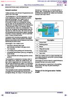
1. Oil pressure sensor Oil pressure, at operation temperature, min 120°C (248°F)
At rated speed: TD720GE, TAD720/721/722GE, TAD730-733GE:400 kPa (58 psi) TD720VE/TAD722/750/760VE: .......................... 450 kPa (65 psi) TAD720VE/TAD721VE: ..................................... 350 kPa (50.8 psi) Idling speed (800 rpm), min: .................................. 80 kPa (11.6 psi) Shut down switch, at pressure lower than: TD720GE, TAD720/721/722GE, TAD730-731GE: 150 kPa (22 psi) TD720VE, TAD720/721/722/750/760VE: ............ 50 kPa (7.2 psi) TAD732/733GE .................................................. 200 kPa (29 psi) 2. Tappet with pulse lubrication 3. Pushrod, oil supply for rocker arm lubrication 4. Rocker arm 5. Return line to oil sump 6. Piston cooling: ................................................ 2-hole nozzles for each cylinder 7. Oil filter, full-flow: Filtering size: ......................................................... 0.012 mm (0.0005") Bypass valve oil filter: Opening pressure: ............................................... 250±50 kPa (35±7 psi) 8. Pressure regulating valve: Opening pressure: ............................................... 400±40 kPa (58±6 psi) 9. Pressure-relief valve: Opening pressure: .............................................. 1±0.1 MPa (145±14 psi) 10. Lube oil pump: Type: .................................................................... Rotary pump driven by the crankshaft Rotary pump width: ............................................... 14.5 mm (0.57") Oil flow (2500 rpm): ............................................... 90 l/min (24 gal/hour) 11. Oil cooler: Normal oil temperature: .......................................... 80°C (176°F) Max o il temperature: ............................................. 125°C (257°F) 71
Technical Data: TD/TAD720-722, TAD730/733, TAD750/760
Fuel system (720– 733)
1. Fuel tank. Max height above fuel pump. 2 meter (6.5 ft) Max suction height to fuel pump. 1.5 meter (4.9 ft) 2. Fuel line (to pump). Inside diameter. min 12 mm (0.47")1) 3. Fuel pump 4. Line to fuel filter. Inside diameter. min 12 mm (0.47")1) 5. Fuel filter 6. Fuel line (to fuel duct). 7. Injection pumps,720/721/722 (6 ea.) 8. Delivery pipe to injector. 9. Injector 10. Fuel return line 11. Overflow valve2) 12. Return fuel line to fuel tank. Inside diameter, min 12 mm (0.47")1) 13. Fuel pipes, minimum distance 300 mm (11.8") 14. Pre-filter for water separating 15. Hand pump (accessory) 1) 2)
Depending on length of hose Can also be used as an air ventilation screw
72
Group 20
Group 20
Technical Data: TD/TAD720-722, TAD730-733, TAD750/760
Fuel system (750,760)
1. 2. 3. 4. 5. 6. 7.
Fuel tank Hand pump (accessory) Fuel line (to pump) Fuel pump Fuel filter Pipe to highpressure Rail
8. 9. 10. 11. 12. 13.
Highpressure pump Fuelpipe, to injector Injector M-prop Pressure valve Return fuel line, to fuel tank, A = Fuel pipes, minimum distance 300 mm (11.8")
73
Technical Data: TD/TAD720-722, TAD730-733, TAD750/760
Group 20
Fuel specification The fuel must be approved according to national and international standards for commercial fuels for example: EN 590 (with environmental and sub-zero temperature specifications according to national requirements) ASTM D 975 No 1-D and 2-D JIS KK 2204 Sulfur content: According to current legislation in the respective country. NOTE! Fuels with extremely low sulfur contents (ex City diesel in Sweden and Finland) can cause a drop in power output of 5% and an increase in fuel consumption of 2–3%.
In
Out
Fuel feed pump Fuel system figures is corresponding to the picture above Overpressure relief valve (1): Opening pressure ............................................... 0.6±0.05 MPa Bypass valve (2) Opening pressure ............................................... 50±5 kPa Fuel flow Min fuel flow at 1500 rpm ...................................... 600 l/tim Firing sequence .................................................... 1-5-3-6-2-4 Feed pressure ....................................................... 0.5 MPa Feed pressure after fuel filter at 1500 rpm. min .................................................... 0.28 MPa
(87±7.2 psi)1) (7.2±0.7 psi) (158.5 gal/hour) (72.5 psi) (40.6 psi)
Fuel filter Filtering size ......................................................... 0.005 mm
(0.0002")
Pre-filter Filtering size ......................................................... 0.006 mm
74
(0.00024")
Group 20
Technical Data: TD/TAD720-722, TAD730/733, TAD750/760
Injection pump (720– 733) Basic measurements The injection pumps are made by BOSCH and are of a single type, that mean one for each cylinder. During the manufacturing of the injection pumps, it is found that the length will varies from pump to pump. This is due to manufacturing tolerances and this is called A/100. The pump length is defined by adding the basic measurement LO with the tolerance A/100, that are written on the injection pump (LFB = LO + A/100). Explanation: LFB = The exact point when injection pumps starts delivering fuel. LO = Basic measurement for the injection pumps A/100 = Manufacturing tolerances (written on the injection pump). Example: If LO is 117.5 mm and A/100 is 63. This gives us the equation: LFB = 143 + 0.63 The total length LFB = 143.63
Injection pump (720–733) Manufacturer ......................................................... Bosch Designation ........................................................... PF 33 L Length A: .............................................................. 54 mm Basic measurement length LO : ............................. 143 mm Min length LFB : (A/100+143) – 143 ........................ >0 mm
(2.12") (5.63")
Injectors Opening pressure: TD720GE/ EPA1, TD720VE/EPA1 TAD720VE/EPA1, TAD721VE/EPA1: ................ 25 MPa (3600 psi) TAD720GE/COM2, TAD720VE/COM2 TAD721VE/COM2, TAD722VE/COM2 TAD721GE/COM2, TAD722GE/COM2: .............. 27,5 MPa (4000 psi) Max pressure: TD720GE/ EPA1, TAD720GE/EPA1/COM2 TAD720VE/EPA1, TAD721VE/EPA1 TAD721GE/COM2, TAD722GE/COM2: .............. 120 MPa (17400 psi) TAD720VE/COM2, TAD721VE/COM2 TAD722VE/COM2: ............................................. 160 MPa (23200 psi) Check leakage (for 10 min): TAD720GE/EPA1, TAD720VE/COM2 TAD721VE/COM2, TAD722VE/COM2: .............. 23 MPa (3340 psi) TAD720GE/EPA1, TAD720VE/EPA1 TAD721GE/COM2, TAD722GE/COM2 TAD721VE/EPA1: ............................................. 25,5 MPa (3700 psi) Numbers/bore Ø: TD720GE: .......................................................... 6 x 0.234 mm (6 x 0.00921") TAD720GE/TD720VE/TAD720VE, EPA 1: ........ 6 x 0.25 mm (6 x 0.00921") TAD721GE/TAD721VE/TAD722GE, EPA 1: ...... 6 x 0.264 mm (6 x 0.00921") TAD720VE/TAD721GE/TAD721VE/TAD722GE COM 2: .............................................................. 6 x 0.236 mm (6 x 0.00921") 75
Technical Data: TD/TAD720-722, TAD730/733, TAD750/760
Group 20
Commencement of delivery (FB) 720–733 The engine is equipped with a separate injection pump for each cylinder. This means that the commencement of delivery (FB), when necessary, has to be adjusted separate for each pump unit. The commencement of delivery (FB) is adjusted with a shim, placed between lifter and injection pump. For exchange of injection pump without any parts of vital importance has been replaced, see chapter ”EP code”. For renovation or when any parts of vital importance have been replaced, special tools (999 8685 and 999 8679) must be used, to be able to calculate the thickness for the new shim. The value for commencement of delivery and camshaft type is indicated on the identification plate, see ”General information”, ”Identification plate”. When calculating the shim thickness, apply a mathematical formula, see ”Theoretical thickness for shim”, where some values are from table 1 and other are measured on the engine. For complete instruction, see ”Workshop Manual”.
Table 1 (Commencement of delivery) All measurements are in mm (1 mm = 0.0394")
FB (Commencement of delivery)
76
Camshaft types
Vh Pre-stroke
Vhcorr.factor
Lo
Pre-stroke Basic dimension correction factor Injection pump
Group 20
Technical Data: TD/TAD720-722, TAD730/733, TAD750/760
Theoretical thickness for a new shim (720–733) Computation for determining the theoretical shim thickness (TS) : TS= L - [ ( FBactual - FBnom ) x Vhcorr.factor + Vhnom + LO + A/100 ] (mm) The correction factor Vhcorr.factor is taken from the table on previous page. The individual steps: 1st step: E1 = FBactual - FBnom (°C/A)
· · · · · · ·
2nd step: E2 = E1 x Vhcorr.factor (mm/°C/A) 3rd step: E3 = E 2 + Vh nom 4th step: E4 = E 3 + LO 5th step: E5 = E4 + A/100 (mm) 6th step: Ts = L – E5 7th step: The actual shim thickness (Ss) is determined with the help of table 2.
NOTE! Shims (Ss) are only available in a calibrated thickness, with a variation of steps in 1/10 mm. When the theoretical shim thickness (Ts) are in the 1/100 range, use table 2 to convert it into the correct shim thickness (Ss)
Table 2 (Shim thickness) All measurements are in mm (1 mm = 0.0394")
Theor. thickness (TS)
Shim thickness (S S)
Theor. thickness(TS)
Shim thickness (SS)
NOTE! Shims (Ss) are only available in a calibrated thickness, with a variation of steps in 1/10 mm. When the theoretical shim thickness (Ts) are in the 1/100 range, use table 2 to convert it into the correct shim thickness (Ss). Important! Use only one shim at the time.
77
Technical Data: TD/TAD720-722, TAD730/733, TAD750/760
Group 20
How to use EP code (720–733) For exchange of injection pump without any parts of vital importance has been replaced, applies a simplified method, when there is only the tolerance between the new and old injection pump that is the difference. TS = EK - (LO + A/100) TS = Shim thickness EK = Value from tabel 3 read with help of EP code from ”Identification plate”. LO = Basic measurement for the injection pumps, 420/620 = 117.5 mm. A/100 = Manufacturing tolerance Example: On Identification plate there is an EP code value for each cylinder. Read the EP code for actual cylinder and with help of this value it is possible to read the new EK value with help of table 3. If read EP code is ”364” that gives a EK value of 146.675 and if the manufacturing tolerance for the new injection pump is ”63” we will have following equation: TS = 146.675 – (143 + 0.63) TS are in this case 3.045 and a control in table 2 gives: SS = 3 mm Thickness on the new shim to be mounted is in this example will be 3 mm
Table 3, EP code conversion table All measurements are in mm (1 mm = 0.0394")
Ek(mm)
78
EP code
Ek(mm)
EP code
Ek(mm)
EP code
Ek(mm)
EP code
Ek(mm)
EP code
Group 20
Technical Data: TD/TAD720-722, TAD730/733, TAD750/760
Governor (720–733) The governors are mechanical variable-speed governors with centrifugal measuring element by M/s Heinzmann. The governor unique prepared for each engine. This means that the governor can not be exchanged between different engines. An incorrect adjusted governor can result in that the engine will not fulfill the regulations for emission and performance. Important! Only trained personnel should make adjustments on the governor, using a test bench specially set up for the Heinzmann governor. Manufacturer ......................................................... Heinzmann Designation: TD720GE/TAD720GE/TAD730–733GE: ............. 1500 rpm TD720GE/TAD720GE/TAD730–733GE: ............. 1800 rpm TD720VE: .......................................................... 1800 rpm TAD720/721/722VE: .......................................... 2100 rpm TAD720/721/722VE: .......................................... 2200 rpm TAD720/721/722VE: .......................................... 2300 rpm Max, engine speed droop at a load increase from 0 to 100 % at: rated speed TD720GE/TAD720GE: .......................................