Volvo 952VE Workshop [PDF]
Workshop Manual Group 20 Technical Data I 1(0) TAD940GE, TAD941GE TAD940VE, TAD941VE, TAD942VE, TAD943VE TAD950VE, TAD
39 2 904KB
Papiere empfehlen


![Volvo 952VE Workshop [PDF]](https://vdoc.tips/img/200x200/volvo-952ve-workshop.jpg)
- Author / Uploaded
- Edson Goncalves
Datei wird geladen, bitte warten...
Zitiervorschau
Workshop Manual Group 20 Technical Data
I 1(0)
TAD940GE, TAD941GE TAD940VE, TAD941VE, TAD942VE, TAD943VE TAD950VE, TAD951VE, TAD952VE
Technical data Industrial Engines TAD940GE, TAD941GE TAD940VE, TAD941VE, TAD942VE, TAD943VE TAD950VE, TAD951VE, TAD952VE Contents Safety information ................................................ General information ............................................. Technical data ...................................................... General ............................................................... Engine ................................................................ Valve mechanism ............................................... Timing gear ......................................................... Reciprocating components .................................. Lubrication and oil systems................................. Fuel system ........................................................ Inlet and exhaust system .................................... Cooling system ................................................... Engine control system ........................................ Tightening torque ................................................ References to Service Bulletins ..........................
2 5 6 6 8 10 14 16 19 22 23 24 25 27 36
Group 20
Safety information This workshop manual contains technical data, descriptions and repair instructions for the Volvo Penta products or product versions noted in the table of contents. Make sure that you use the correct workshop literature.
Read the available safety information, ”General information” and ”Repair instructions” in the workshop manual before you start to do any service work.
Important The following special warning signs are used in the workshop manual and on the product. WARNING! Warns for the risk of personal injury, major damage to product or property, or serious malfunctions if the instruction is ignored. IMPORTANT! Is used to call attention to things which could cause damage or malfunctions to product or property. NOTE! Is used to call attention to important information, to facilitate work processes or operation. To give you a perspective on the risks which always need to be observed and precautions which always have to be taken, we have noted them below.
Make it impossible to start the engine by cutting system current with the main switch(es) and lock it (them) in the off position before starting service work. Fix a warning sign by the control station.
All service work should normally be done on a stationary engine. Some work, such as adjustments, need the engine to be running, however. Going close to a running engine is a safety risk. Remember that loose clothes, long hair etc. can catch on rotating components and cause severe injury. If work is done adjacent to a running engine, a careless movement or a dropped tool can lead to personal injury in the worst case. Take care to avoid contact with hot surfaces (exhaust pipes, turbocharger, charge air pipe, starter heater etc.) and hot fluids in pipes and hoses in an engine which is running or has just been stopped. Reinstall all protective parts removed during service operations before starting the engine.
Check that the warning or information labels on the product are always clearly visible. Replace labels which have been damaged or painted over.
Never start the engine without installing the air cleaner (ACL) filter. The rotating compressor turbine in the turbocharger can cause severe injury. Foreign objects entering the intake ducts can also cause mechanical damage.
Never use start spray or similar products as a starting aid. They may cause an explosion in the inlet manifold. Danger of personal injury.
Only start the engine in a well- ventilated area. When operated in a confined space, exhaust fumes and crankcase gases must be ventilated from the engine bay or workshop area.
Avoid opening the coolant filling cap when the engine is hot. Steam or hot coolant can spray out and the system pressure will be lost. When needed, open the filler cap slowly and release the pressure in the system. Be extremely careful if a tap, plug or coolant hose has to be removed from a hot engine. It is difficult to anticipate in which direction steam or hot coolant can spray out.
Hot oil can cause burns. Avoid skin contact with hot oil. Ensure that the lubrication system is not under pressure before carrying out any work. Never start or operate the engine with the oil filler cap removed, otherwise oil could be ejected.
Group 20 Stop the engine before carrying out operations on the engine cooling system.
Always use protective glasses or goggles when carrying out work where there is a risk of splinters, grinding sparks, acid splashes or where other chemicals are used. Your eyes are extremely sensitive, injury could cause blindness!
Avoid getting oil on your skin! Repeated exposure to oil or exposure over a long period can result in the skin becoming dry. Irritation, dryness and eczema and other skin problems can then occur. Used oil is more dangerous than fresh oil from a health aspect. Use protective gloves and avoid oil soaked clothes and shop rags. Wash regularly, especially before eating. There are special skin creams which counteract drying out of the skin and make it easier to clean off dirt after work is completed.
Most chemicals intended for the product (e.g. engine and transmission oils, glycol, petrol (gasoline) and diesel oil) or chemicals for workshop use (e.g. degreasers, paints and solvents) are hazardous. Read the instructions on the product packaging with care! Always follow the safety precautions for the product (for example use of protective mask, glasses, gloves etc.). Make sure that other personnel are not exposed to hazardous chemicals, for example in the air. Ensure good ventilation in the work place. Follow the instructions provided when disposing of used or leftover chemicals.
Exercise extreme care when leak detecting on the fuel system and testing the fuel injector nozzles. Use eye protection. The jet from a fuel injector is under very high pressure, and has considerable penetration ability; fuel can force its way deep into body tissues and cause serious damage. Danger of blood poisoning (septicemia).
WARNING! The delivery pipes must under no circumstances be bent. Damaged pipes must be replaced.
General instructions All fuels, and many chemicals, are flammable. Do not allow naked flame or sparks in the vicinity. Certain thinners and hydrogen from batteries can be extremely flammable and explosive when mixed with air in the right proportions. No Smoking! Ensure that the work area is well ventilated and take the necessary safety precautions before starting welding or grinding work. Always ensure that there are fire extinguishers at hand when work is being carried out.
Make sure that oil and fuel soaked rags, and used fuel and oil filters are stored in a safe place. Rags soaked in oil can spontaneously ignite under certain circumstances. Used fuel and oil filters are polluting waste and must be handed to an approved waste management facility for destruction, together with used lubrication oil, contaminated fuel, paint residue, solvents, degreasers and wash residue.
Batteries must never be exposed to open flames or electric sparks. Do not smoke close to the batteries. The batteries generate hydrogen gas when charged, which forms an explosive gas when mixed with air. This gas is easily ignited and highly volatile. A spark, which can be formed if the batteries are wrongly connected, is enough to make a battery explode and cause damage. Do not shift the connections when attempting to start the engine (spark risk) and do not lean over any of the batteries.
Never mix up the battery positive and negative poles when the batteries are installed. Incorrect installation can result in serious damage to the electrical equipment. Refer to the wiring diagram.
Always use protective goggles when charging and handling the batteries. Battery electrolyte contains sulfuric acid, which is highly corrosive. Should the battery electrolyte come into contact with unprotected skin wash off immediately using plenty of water and soap. If you get battery acid in your eyes, flush it off at once with a generous amount of water, and get medical assistance at once.
General instructions Turn the engine off and turn off the power at the main switch(es) before carrying out work on the electrical system.
Group 20 WARNING! Components in the electrical and fuel systems on Volvo Penta products have been designed to minimize the risks of explosion and fire. The engine must not be operated in environments with adjacent explosive media.
The clutch must be adjusted with the engine shut off.
The existing lugs on the engine should be used for lifting. Always check that the lifting devises are in good condition and that they have the correct capacity for the lift (the weight of the engine plus the reversing gear and extra equipment). The engine should be lifted with a customized or adjustable lifting boom for safe handling and to avoid damaging components on top of the engine. All chains or cables must be parallel to each other and should be as square as possible to the top of the engine. If other equipment connected to the engine has altered its center of gravity, special lifting devises may be needed to obtain the correct balance and safe handling. Never do any work on an engine which just hangs from a liftingdevise.
Never work alone when heavy components are to be dismantled, even when safe lifting devises such as lockable blocks & tackle are used. When using a lifting devise, two people are usually required to do the work, one to take care of the lifting device and another to ensure that components are lifted clear and not damaged during the lifting operations. Always make sure that there is enough space for disassembly where you are working, with no risk for personal or material damage.
4
Only use the fuels recommended by Volvo Penta. Refer to the Instruction Book. Use of fuels that are of a lower quality can damage the engine. In a diesel engine, poor fuel can cause the control rod to bind and the engine will over- rev, entailing a strong risk of personal injury and machinery damage. Poor fuel can also lead to higher maintenance costs.
Remember the following when washing with a high pressure washer: Never aim the water jet at air filters, seals, rubber hoses or electrical components. Never use a high pressure washer for engine cleaning.
The injectors can leak fuel when the engine is stationary, if the tank is higher than the engine and the fuel pressure is positive.
Group 20
General information About the workshop manual
Certified engines
This workshop manual contains technical data for the TAD940GE, TAD941GE, TAD940VE, TAD941VE, TAD942VE, TAD943VE, TAD950VE, TAD951VE and TAD952VE engines.
The manufacturer certifies that both new engines and those in use, which are certified for national or regional legislation, comply with the environmental requirements. Each product must correspond with the unit used for certification. The following requirements for service and spare parts must be complied with, for Volvo Penta as a manufacturer to be responsible for ensuring that engines in use comply with the stipulated environmental requirements:
The Workshop Manual, Technical Data, contains all the references from the workshop manuals to repair instructions for the TAD940GE, TAD941GE, TAD940VE, TAD941VE, TAD942VE, TAD943VE, TAD950VE, TAD951VE and TAD952VE series. The Workshop Manual is produced primarily for the use of Volvo Penta workshops and service technicians. For this reason the manual presupposes a certain basic knowledge and that the user can carry out the mechanical/electrical work described to a general standard of engineering competence. Volvo Penta constantly improves its products, so we reserve the right to make modifications without prior notification. All information in this manual is based on product data which was available up to the date on which the manual was printed. Any material changes introduced into the product or service methods after this date are notified by means of Service Bulletins.
Maintenance and service intervals recommended by Volvo Penta must be complied with. Only Volvo Penta Original Spare Parts intended for the certified engine version may be used Service related to injection pumps and injectors must always be done by an authorized Volvo Penta workshop. The engine must not be converted or modified in any way, except for the accessories and service kits which Volvo Penta has approved for the engine. Installation changes to the exhaust pipe and the engine bay air inlet ducts (ventilation ducts) must not be done without further discussion, since this could affect exhaust emissions.
Spare parts Spare parts for electrical and fuel systems are subject to various national safety requirements. Volvo Penta Original Spares comply with these requirements. No damage whatever, occasioned by use of non-original Volvo Penta spares for the product, will be compensated by the warranty offered by Volvo Penta.
No seals may be broken by unauthorized personnel. The general advice in the instruction book about operation, care and maintenance applies. IMPORTANT! When spare parts are needed, use only Volvo Penta Original Spares. Use of non-original spareparts means that AB Volvo Penta can no longer be responsible for guaranteeing that the engine complies with the certified version. Any damage, injury and/or costs which arise due to the use of non-original Volvo Penta spares for the product in question will not be compensated by Volvo Penta.
5
Group 20
Technical data General Type designation
TAD940GE
Power, Prime/Stand-by
See Sales Guide Generating Set Engines
Torque, Prime/Stand-by
See Sales Guide Generating Set Engines
Compression ratio Low idle (rpm) High idle (rpm)
TAD941GE
20,2:1
17,4:1
600-1200
600-1200
1500-1620/1800-1920 1500-1620/1800-1920
No. of valves
24
24
No. of cylinders
6
6
Cylinder bore (mm)
120
120
Stroke (mm)
138
138
Swept volume (dm )
9.36
9.36
Weight, dry (kg)
1015
1015
Weight, wet (kg)
1065
1065
1-5-3-6-2-4
1-5-3-6-2-4
3
Injection sequence
Type designation
TAD940VE
TAD941VE
TAD942VE
Power
See Sales Guide Industrial Diesel Power
Torque
See Sales Guide Industrial Diesel Power
Compression ratio
TAD943VE
20.2:1
20.2:1
20.2:1
20.2:1
Low idle (rpm)
600
600
600
600
High idle (rpm)
2250
2250
2250
2250
No. of valves
24
24
24
24
No. of cylinders
6
6
6
6
Cylinder bore (mm)
120
120
120
120
Stroke (mm)
138
138
138
138
Swept volume (dm )
9.36
9.36
9.36
9.36
Weight, dry (kg)
1015
1015
1015
1015
Weight, wet (kg)
1065
1065
1065
1065
1-5-3-6-2-4
1-5-3-6-2-4
1-5-3-6-2-4
1-5-3-6-2-4
3
Injection sequence
(1 mm = 0.03937 inch)
6
Group 20
Type designation
Technical data
TAD950VE
TAD951VE
Power
Please refer to the sales literature
Torque
Please refer to the sales literature
Compression ratio
TAD952VE
20.2:1
20.2:1
20.2:1
Low idle (rpm)
600
600
600
High idle (rpm)
2250
2250
2250
No. of valves
24
24
24
No. of cylinders
6
6
6
Cylinder bore, mm (inch)
120 (4.72)
120 (4.72)
120 (4.72)
Stroke, mm (inch)
138 (5.43)
138 (5.43)
138 (5.43)
Swept volume, dm3 (US quart)
9.36 (9.89)
9.36 (9.89)
9.36 (9.89)
Weight, dry, kg (lb)
1015 (2238)
1015 (2238)
1015 (2238)
Weight, wet, kg (lb)
1065 (2348)
1065 (2348)
1065 (2348)
Injection sequence
1-5-3-6-2-4
1-5-3-6-2-4
1-5-3-6-2-4
7
Group 20
Engine Engine block Length .................................................................... 967 mm (38.07") Height, upper block plane - crankcase centerline ... 379 mm (14.92") Height lower block plane - crankcase centerline ..... 120 mm (4.72") Crankcase pressure normal value, irrespective of engine speed ............. max 0.5 kPa (0.07 psi)
Cylinder head Type ...................................................................... 6-cylinder Length .................................................................... 996 mm (39.21") Width ..................................................................... 410 mm (16.14") Height .................................................................... 135 mm (5.32") Max. flatness error (base plane) ............................. 0.4 mm (0.0158")
Cylinder head screws No. of screws ......................................................... 26 Dimension, thread .................................................. M16 Length .................................................................... 200 mm (7.874")
Cylinder liner Type ...................................................................... Wet, replaceable Height, total. .......................................................... 250 mm (9.8425") Sealing surface height above block plane .............. 0.15 - 0.20 mm (0.0059 - 0.0079") No. of seal rings per cylinder liner .......................... 3 Cylinder bore .......................................................... 120.00 - 120.02 mm (4,72 - 4,73”)
Piston Type ...................................................................... aluminium Height above engine block plane ............................ 0.15 -0.65 mm (0.0059 - 0.0256") Diameter, combustion chamber TAD940GE, TAD940-943VE ............................... 77 mm (3.032") TAD941GE ......................................................... 78,5 mm (3.090") TAD950-52VE ..................................................... 77,1 mm (3.035") Depth, piston bowl TAD940GE, TAD940-943VE ............................... 15 mm (0.590") TAD941GE ......................................................... 17,3 mm (0.681") TAD950-952VE ................................................... 14,6 mm (0.575") No. of ring grooves ................................................. 3 Front marking ......................................................... Arrow towards front Gudgeon pin diameter ............................................ 54 mm (2.126")
8
Group 20
Technical data
Piston rings Compression rings Specification: Quantity ................................................................. 2 Piston ring clearance in groove upper compression ring ....................................... 0.12 -0.19 mm (0.0047 - 0.0075") lower compression ring ....................................... 0.09 -0.13 mm (0.0035 - 0.0051") Piston ring gap, measured at ring opening: upper compression ring ....................................... 0.35 -0.55 mm (0.013779 - 0.021653") lower compression ring ....................................... 1.15 -1.3 mm (0.045275 - 0.051181")
Oil scraper ring: Quantity ................................................................. 1 Width, including spring ........................................... 4.3 mm (0.011811") Piston ring clearance in groove, ............................. 0.05 -0.10 mm (0.001968 - 0.003937") Piston ring gap, measured at ring opening .............. 0.35 -0.75 mm (0.013779 - 0.029527")
9
Technical data
Valve mechanism Valves
Valve head, diameter: Inlet .................................................................... 38 mm (1.49606") Exhaust TAD940-941GE, TAD940-943VE ...................... 38 mm (1.49606") TAD950-952VE ................................................. 36 mm (1.41732") Valve stem, diameter: Inlet .................................................................... 8 mm (0.31496") Exhaust .............................................................. 8 mm (0.31496") Valve seat angle (A): Inlet .................................................................... 29.5° Exhaust .............................................................. 29.5° Seat angle in cylinder head (B): Inlet .................................................................... 30° Exhaust .............................................................. 30° Dimension between valve head and cylinder head plane: Inlet .................................................................... min 0.95 mm (0.037401") Exhaust .............................................................. min 1.25 mm (0.049212") NOTE! When the valve seats are changed, the valves must be changed at the same time. Valve clearance, cold engine, setting value: Inlet .................................................................... 0.2 mm (0.007874") Exhaust TAD940-941GE, TAD940-943VE ...................... 0.5 mm (0.019685") TAD950-952VE ................................................. 0,8 mm (0.031496") Valve clearance, cold engine, check value: Inlet .................................................................... 0.15 -0.25 mm (0.005905 - 0.009842") Exhaust TAD940-941GE, TAD940-943VE ...................... 0.45 -0.55 mm (0.017716 - 0.021653") TAD950-952VE ................................................. 0,75 - 0,85 mm (0.029527 - 0.033465") TAD950-952VE Clearance, double rocker arm – base circle on camshaft ...................................... using gauge tool
10
Group 20
Group 20
Technical data
Valve seats
Outer diameter (A) Standard: Inlet .................................................................... TAD940-941GE, TAD940-943VE ...................... 40.0 mm (1.5748") TAD950-952VE ................................................. 42,0 mm (1.6535") Exhaust TAD940-941GE, TAD940-943VE ...................... 41.0 mm (1.61417") TAD950-952VE ................................................. 40,0 mm (1.5748") Oversize dimension: Inlet TAD940-941GE, TAD940-943VE ...................... 40.3 mm (1.586611") TAD950-952VE ................................................. 42,3 mm (1.665349") Exhaust TAD940-941GE, TAD940-943VE ...................... 41.3 mm (1.625981") TAD950-952VE ................................................. 40,3 mm (1.586609") Height (B): Inlet TAD940-941GE, TAD940-943VE ...................... 7.3 mm (0.287401") TAD950-952VE ................................................. 7,4 mm (0.291338") Exhaust TAD940-941GE, TAD940-943VE ...................... 7.4 mm (0.291338") TAD950-952VE ................................................. 6,4 mm (0.251968")
11
Technical data
Valve seat bed
Diameter (C) standard: Inlet TAD940-941GE, TAD940-943VE ...................... 40.0 mm (1.5748") TAD950-952VE ................................................. 42,0 mm (1.6535") Exhaust TAD940-941GE, TAD940-943VE ...................... 41.0 mm (1.61417") TAD950-952VE ................................................. 40,0 mm (1.5748") Diameter (C) oversize dimension: Inlet TAD940-941GE, TAD940-943VE ...................... 40.2 mm (1.582674") TAD950-952VE ................................................ 42,2 mm (1.661412") Exhaust TAD940-941GE, TAD940-943VE ...................... 41.2 mm (1.622044") TAD950-952VE ................................................. 40,2 mm (1.582672") Depth (D): Inlet .................................................................... 11.5 mm (0.452755") Exhaust .............................................................. 11.9 mm (0.468503") Seat base radius (R): Inlet .................................................................... max 0.8 mm (0.031496") Exhaust .............................................................. max 0.8 mm (0.031496")
12
Group 20
Group 20
Technical data
Valve guides Length: Inlet .................................................................... 83.4 mm (3.283458") Exhaust .............................................................. 83.4 mm (3.283458") Inner diameter: Inlet .................................................................... 8 mm (0.31496") Exhaust .............................................................. 8 mm (0.31496") Height above cylinder head spring plane: Inlet .................................................................... 24.5±0.5 mm (0.964564 ± 0.019685") Exhaust .............................................................. 16.5±0.5 mm (0.6496043 ± 0.019685") Clearance, valve stem - guide:1 Inlet .................................................................... max 0.2 mm (0.007874") Exhaust .............................................................. max 0.2 mm (0.007874") 1
The dimensions have been calculated for the method of measurement described in the workshop manual (group 21).
Rocker arms Bearing clearance .................................................. max 0.08 mm
Valve springs Inlet Outer valve springs: Unloaded length .................................................. 73.8 mm (2.905506") With 590 N (132.6 lbf) loading ............................. 58.4 mm (2.299208") With 1150 N (258.5 lbf) loading ........................... 45.3 mm Coilbound length, max ......................................... 39.5 mm (1.555115") Inner valve spring: Unloaded length .................................................. 70.5 mm (2.775585") With 243 N (54.6 lbf) loading ............................... 54.4 mm (2.141728") With 447 N (100.4 lbf) loading ............................. 41.3 mm (1.625981") Coilbound length, max ......................................... 36.5 mm (1.437005") Exhaust Outer valve springs: Unloaded length .................................................. 73.8 mm (2.905506") With 590 N (132.6 lbf) loading ............................. 58.4 mm (2.299208") With 1150 N (258.5 lbf) loading ........................... 45.3 mm (1.783461") Coilbound length, max ......................................... 39.5 mm (1.555115") Inner valve spring: Unloaded length .................................................. 70.5 mm (2.775585") With 243 N (54.6 lbf) loading ............................... 54.4 mm (2.141728") With 447 N (100.4 lbf) loading ............................. 41.3 mm (1.625981") Coilbound length, max ......................................... 36.5 mm (1.437005")
13
Technical data
Timing gear Timing gear wheels
No. of teeth: 1. Drive gear, crankshaft .......................................... 54 2.
Idler wheel, double, outer ...................................... 72 Idler wheel, double, inner ...................................... 56
3.
Idler wheel, adjustable .......................................... 73
4.
Drive gear, camshaft ............................................ 84
5.
Idler wheel, servo pump ........................................ 37
6.
Drive wheel, steering servo and fuel feed pump .... 31
7.
Drive wheel, air compressor ................................. 42
8.
Drive wheel, lubricating oil pump .......................... 23
Gear backlash min ..................................................................... 0.05 mm (0.001968") max .................................................................... 0.17 mm (0.006692") Shaft stub for idler wheel, diameter ........................ 100 mm (3.937") Bushing for idler wheel, diameter ............................ 100 mm (3.937") Radial clearance for idler wheel .............................. max 0.05 mm (0.001968")
14
Group 20
Group 20
Technical data
Camshaft Check camshaft setting, cold engine and valve clearance =0. Inlet valve for cylinder 1 at flywheel position 6 ATDC must be open 1.3±0.3 mm (0.05118±0.0118"). During the check, you must turn the timing gear in the correct direction (clockwise seen from the front), to take up all gear flank clearance. Drive ...................................................................... gear wheel No of bearings ........................................................ 7 Diameter, bearing journals, standard ...................... 69.97 -70.00 mm (22.754718 - .7559") NOTE! Only check values, not for machining. Diameter, bearing journals, undersize dimension 0.25 .................................................................... 69.72 -69.78 mm (2.744876 - 2.747238") 0.50 .................................................................... 69.47 -69.53 mm (2.735033 - 2.737396") 0.75 .................................................................... 69.22 -69.28 mm (2.725191 - 2.727553") Max. end float ........................................................ 0.24 mm (0.009448") Max permissible ovality (with new bearings) ........... 0.05 mm (0.001968") Bearing, max. permissible wear on diameter .......... 0.05 mm (0.001968") Valve lift: inlet ..................................................................... 13 mm (0.51181") outlet (EPG) ........................................................ 12 mm (0.47244") Permissible wear between base circle and max. lift ....................................................... max 0.1 mm (0.003937") Unit injector, stroke ................................................ 13 mm (0.51181")
Camshaft bearings Camshaft bearing thickness, standard ................... 1.92 mm (0.075590") Oversize dimension: 0.25 .................................................................... 2.04 mm (0.080314") 0.50 .................................................................... 2.17 mm (0.085432") 0.75 .................................................................... 2.29 mm (0.090157")
15
Technical data
Reciprocating components Crankshaft Length .................................................................... 1.066 mm (0.041968") Crankshaft, end float1 .............................................0.10–0.40 mm (0.0039–0.0157") Ovality of main and big end bearings ..................... max 0.01 mm (0.000393") Taper of main and big end bearings ....................... max 0.02 Runout on center bearing ....................................... 0.15 mm (0.005905") 1
Dimensions refer to oiled components.
Main bearing journal NOTE! Only check values, not for machining. Diameter (Ø) standard ............................................ 108.0 mm (4.25196") Undersize dimension: 0.25 mm ............................................................. 107.85 -107.87 mm (4.246054 - 4.246841") 0.50 mm ............................................................. 107.73 -107.75 mm (4.241330 - 4.242117") 0.75 mm ............................................................. 107.60 -107.62 mm (4.236212 - 4.236999") 1.00 mm ............................................................. 107.48 -107.50 mm (4.231487 - 4.232275") 1.25 mm ............................................................. 107.35 -107.37 mm (4.226369 - 4.227156") Surface finish, main bearing journal ....................... Ra 0.25 Surface finish, radius ............................................. Ra 0.4 Width, main bearing journal (A) standard ................ 42 mm (1.65354") Oversize dimension: 0.2 mm (thrust bearing 0.1) ................................. 42.17 -42.22 mm (1.660232 - 1.662201") 0.4 mm (thrust bearing 0.2) ................................. 42.37 -42.42 mm (1.668106 - 1.670075") 0.6 mm (thrust bearing 0.3) ................................. 42, 57-42.62 mm (1.65354 - 1.677949") Fillet radius (R) ....................................................... 4.5 mm (0.177165")
16
Group 20
Group 20
Technical data
Thrust washers (thrust bearing) Width (B) standard ................................................. 3.2 mm (0.125984") Oversize dimension: 0.1 mm ............................................................... 3.2 -3.3 mm (0.125984 - 0.129921") 0.2 mm ............................................................... 3.3 -3.4 mm (0.129921 - 0.133858") 0.3 mm ............................................................... 3.4 -3.5 mm (0.133858 - 0.137795")
Main bearing shells Outer diameter (C) ................................................. 113 mm (4.44881") Thickness (D) standard .......................................... 2.5 mm (0.098425") Oversize dimension: 0.25 mm ............................................................. 2.6 -2.7 mm (0.102362 - 0.106299") 0.50 mm ............................................................. 2.7 -2.8 mm (0.106299 - 0.110236") 0.75 mm ............................................................. 2.8 -2.9 mm (0.110236 - 0.114173") 1.00 mm ............................................................. 2.9 -3.0 mm (0.114173 - 0.11811") 1.25 mm ............................................................. 3.1-3.2 mm (0.122047 - 0.125984") Radial clearance, main bearings ............................. max 0.11 mm (0.004330")
Big end bearing journal NOTE! Only check values, not for machining. Diameter (Ø) .......................................................... 88 mm (3.46456") Undersize dimension: 0.25 mm ............................................................. 87.85 -87.87 mm (3.458654 - 3.459441") 0.50 mm ............................................................. 87.73 -87.75 mm (3.453930 - .3454717") 0.75 mm ............................................................. 87.60 -87.62 mm (3.448812 - 3449599") 1.00 mm ............................................................. 87.48 -87.50 mm (3.444087 - 3.444875") 1.25 mm ............................................................. 87.35 -87.37 mm (3.438969 - 3.439756") Surface finish, big end bearing journal .................... Ra 0.25 Surface finish, radius ............................................. Ra 0.4 Width (A) ................................................................ 54 mm (2.12598") Fillet radius (R) ....................................................... 4.5 mm (0.177165")
17
Technical data
Group 20
Big end journal shells Outer diameter (B) ................................................. 93 mm (3.66141") Thickness (C) standard .......................................... 2.4 mm (0.094488") Oversize dimension: 0.25 mm ............................................................. 2.5 -2.6 mm (0.098425 - 0.102362") 0.50 mm ............................................................. 2.6 -2.7 mm (0.102362 - 0.106299") 0.75 mm ............................................................. 2.7 -2.8 mm (0.106299 - 0.110236") 1.00 mm ............................................................. 2.8 -2.9 mm (0.110236 - 0.114173") 1.25 mm ............................................................. 3.0 -3.1 mm (0.11811 - 0.122047") Diameter, bearing shell seat (D) ............................. 92.85 mm (3.655504")
Con rods Length, center - center (E) ..................................... 225 mm (8.85825") Small end bushing, internal diameter (G) ................ 54 mm (2.12598") End float, con rod - crankshaft1: ............................. max 0.35 mm (0.013779") Big end bearing, radial clearance 1: ....................... max 0.10 mm (0.003937") Straightness, max. deviation on 100 mm (3.937") measured length .................................................... 0.06 mm (0.002362") Twist, max. deviation on 100 mm (3.937") measured length .................................................... 0.15 mm (0.005905") 1
Dimensions refer to oiled components.
Marking: ”FRONT” on the con rod faces forwards. The con rods and caps are marked in pairs, using a three digit serial number (please refer to the illustration).
Flywheel, installed Runout (manual gearbox), measurement radius 150 mm (5.9055") . ...................................... max 0.20 mm (0.007874") No. of teeth on starter gear ring .............................. 153 Sensor grooves in flywheel .................................... 54 pcs.
Flywheel housing, installed Runout for mating face against bellhousing. ........... max 0.1 mm (0.003937") Radial runout for alignment against bellhousing. ..... max 0.05 mm (0.001968")
18
Group 20
Technical data
Lubrication oil systems TAD940-941GE, TAD940-943VE Sulfur content in fuel, by weight < 0.5 %
Oil grade
> 1.0 %1)
0.5 – 1.0 %
Oil change interval: Reached first in operation
VDS-3 VDS-2 and ACEA E7 2) VDS-2 and ACEA E5 2) VDS-2 and Global DHD-1 2) VDS-2 and API CI-4 2) VDS-2 and API CH-4 2)
600 hours / 12 month
300 hours / 12 month
150 hours / 12 month
VDS and ACEA E3 2)
400 hours / 12 month
200 hours / 12 month
100 hours / 12 month
ACEA: E7, E5, E4 API: CI-4, CH-4, CG-4
200 hours / 12 month
100 hours / 12 month
50 hours / 12 month
TAD950-952VE Sulfur content in fuel, by weight < 0.3 %
Oil grade
1) 2)
0.3 – 0.5 %
> 0.5 %1)
Oil change interval: Reached first in operation
VDS-3
500 hours / 12 month
250 hours / 12 month
125 hours / 12 month
VDS-2 and ACEA E7 2) VDS-2 and ACEA E5 2) VDS-2 and Global DHD-1 2) VDS-2 and API CI-4 2) VDS-2 and API CH-4 2)
250 hours / 12 month
125 hours / 12 month
75 hours / 12 month
VDS and ACEA E3 2) ACEA: E7, E5, E4 API: CI-4, CH-4, CG-4
125 hours / 12 month
75 hours / 12 month
50 hours / 12 month
If sulfur content is > 1.0 % by weight, use oil with TBN > 15. Lubrication oil must comply with both requirements. Note. API: CG-4 or CH-4 can be approved in markets outside Europe (instead of ACEA A3).
NOTE! Mineral based oil, either fully or semi-synthetic, can be used on condition that it complies with the quality requirements above. NOTE! Oil filter must be changed with every oil change. VDS = Volvo Drain Specification ACEA = Association des Constructeurs Européenne d’Automobiles API = American Petroleum Institute TBN = Total Base Number
19
Technical data
Group 20
Viscosity Select the viscosity from the adjacent table, for the appropriate continuous ambient air temperature.
*
*Refers to synthetic or semi-synthetic oils.
Oil Oil change volume, including filters ........................ 35 liter (9.2 US gallon)
Oil pressure Operating speed (above 1100 rpm) ......................... 300 -550 kPa (43.5-79.7 psi) Low idle .................................................................. min 270 kPa (39.1 psi)
Oil temperature Cold engine, engine stopped .................................. ambient temperature Hot engine, engine running (coolant temperature 75-95 C) (167-203°F) .......... 90-115 C (194-239°F)
Lubricating oil pump Type ...................................................................... Gear driven No. of teeth, drive wheel ........................................ 23
Oil filter Full flow filter .......................................................... 2 Turbo filter (By-pass filter) ...................................... 1
20
Group 20
Technical data
Oil valves
1. Safety valve, lube oil pump Marking ............................................................. Violet 2. Bypass valve, bypass filter Spring, free length ............................................. 69 mm (2.71653") Loaded 13-15 Nm (9.6-11.0 lbf-ft) ...................... 40 mm (1.5748") 3. Bypass valve, oil cooler Spring, free length ............................................. 63 mm (2.48031") Loaded 124 Nm (91.4 lbf-ft) ............................... 44 mm (1.73228") 4. Reduction valve, oil pressure Marking ............................................................. Blue 5. Bypass valve, full flow filter Spring, free length ............................................. 69 mm (2.71653") Loaded 13-15 Nm (9.6-11.0 lbf-ft) ...................... 40 mm (1.5748") 6. Opening valve, piston cooling Spring, free length ............................................. 122 mm (4.80314") Loaded, 94 Nm (69.3 lbf-ft) ................................ 62 mm (2.44094") 7. Control valve, piston cooling Spring, free length ............................................. 122 mm (4.80314") Loaded, 47 Nm (34.6 lbf-ft) ................................ 92 mm (3.62204")
21
Technical data
Group 20
Fuel system Feed pump Feed pressure at: 600 r/min ............................................................. min 400 kPa (58.0 psi) 1200 r/min ........................................................... min 400 kPa (58.0 psi) full load ............................................................... min 400 kPa (58.0 psi)
By-pass valve Opening pressure ................................................... 400 -550 kPa (58.0-79.7 psi)
Fuel quantity At low idle and with the engine unloaded, the fuel quantity should be inside area B. The engine should be run in at least 600 h.
Unit injector Pre-load: ................................................................ 3-4 spanner flats (0.75 ± 0.1 mm (0.029527 - 0.003937")), please refer to the illustration.
Tighten the adjustment screw to zero clearance against the camshaft, then turn 3-4 spanner flats.
22
Group 20
Technical data
Inlet and exhaust system Turbocharger Manufacturer/type TAD940GE, TAD940-943VE ............................... 3K/K29 TAD941GE ......................................................... 3K/K31 TAD950-952VE ................................................... Holset End float, turbine shaft ........................................... max 0.15 mm (0.005905")
Charge air temperature indicator Cold engine, engine stopped .................................. Ambient temperature Hot engine, engine running (coolant temperature 75-95°C (167-203°F)) .......... 10-30°C (18-54°F) above ambient temperature
Pressure drop indicator Pressure drop indicator indication lamp lights up at a pressure drop of ............................. 5 kPa (0.7 psi)
Boost pressure 1500/1800 r/min. TAD940GE ............................................................ 230 kPa (33.36 psi) TAD941GE ............................................................ 250 kPa (36.26 psi) 2100 r/min TAD940VE ............................................................. 145 kPa (21.03 psi) TAD941VE ............................................................. 166 kPa (24.08 psi) TAD942VE ............................................................. 185 kPa (23.83 psi) TAD943VE ............................................................. 187 kPa (27.12 psi) TAD950VE ............................................................. 187 kPa (27.12 psi) TAD951VE ............................................................. 207 kPa (30.02 psi) TAD952VE ............................................................. 212 kPa (30.75 psi)
23
Technical data
Cooling system General Pressure cap opens at ........................................... 75 kPa (10.8 psi)
Thermostat Quantity ................................................................. 1 Opening temperature .............................................. 82°C (180°F) Fully open .............................................................. 92°C (198°F)
Coolant Type ...................................................................... Volvo Original Consists of ............................................................ Glycol and corrosion-inhibiting additives Color ...................................................................... Green Mix with ................................................................. Water (according to ASTM D4985)
24
Group 20
Group 20
Technical data
Engine control system Engine control unit No. of pins ............................................................. 2 x 36
Sensor Charge pressure sensor Check value ........................................................... 1.05-1.30 V at 100 kPa (14.5 psi) Charge air temperature sensor
Coolant temperature sensor
25
Technical data Inlet temperature sensor
Engine oil temperature sensor
Camshaft sensor Distance to camshaft ............................................. 0.3 -1.0 mm (0.011811 - 0.03937") Flywheel sensor Distance to flywheel ............................................... 0.7 -2.1 mm (0.027559 - 0.082677")
26
Group 20
Group 20
Technical data
Tightening torque General tightening torque
Nm
M6 standard screw 8.8 ........................................... 10 ±1.5 (±1.1 lbf-ft) M8 standard screw 8.8 ........................................... 25 ±4 (18.5±2.9 lbf-ft) M10 standard screw 8.8 ......................................... 50±8 (36.9±5.9 lbf-ft) M12 standard screw 8.8 ......................................... 85 ±15 (62.7±11.0 lbf-ft) M14 standard screw 8.8 ......................................... 140 ±25 (103±18.4 lbf-ft) M16 standard screw 8.8 ......................................... 220 ±35 (162±25.8 lbf-ft) Only torqued screws can be re-installed. Torque and angle tightened / plastic limit tightened screws: 8.8 ...................................................................... should not be re-installed 10.9 .................................................................... can be re-installed 12.9 .................................................................... can be re-installed IMPORTANT! Check screws which are to be re-installed. Damaged screws, with marks of seizure etc. under the heads, must be scrapped.
Tightening torque group 21: Engine body Front engine mounting, engine block ...................... 275 ±45 Nm (202±33lbf-ft) Front engine mounting, front engine pad ................. 150 ±30 Nm (111±22 lbf-ft) Main bearing caps Stage 1 ............................................................... 150 ±20 Nm (111±15 lbf-ft) Stage 2 ............................................................... 120° ±5° angle tightening Big end bearing cap Stage 1 ............................................................... 20 ±3 Nm (15±2 lbf-ft) Stage 2 ............................................................... 35 ±3 Nm (26±2 lbf-ft) Stage 3 ............................................................... 90° ±5° angle tightening Stiffening frame ..................................................... 48 ±8 Nm (35±6 lbf-ft) NOTE! Tighten the screws in sequence, from the center and outwards.
27
Technical data
Flywheel NOTE! Make sure that the flange is clean and dry. NOTE! Tighten the screws in number order, as in the illustration. Stage 1 ............................................................... 60 ±5 Nm (44±4 lbf-ft) Stage 2 ............................................................... 120° ±10° angle tightening
Bell housing NOTE! Apply 2 mm silicone sealer as in the illustration.
28
Group 20
Group 20
Technical data
12
1
10
3
8
6
5
7
2 9
4 Vibration damper, camshaft
11
Stage 1 ............................................................... 45 ±5 Nm (33±4 lbf-ft) Stage 2 ............................................................... 90° ±5° angle tightening NOTE! Tighten the screws in number order, as in the illustration. NOTE! The 8.8 screws on the vibration damper must not be re-used.
Housing, crankcase seal ............................. 24 ±4 Nm (18±3 lbf-ft) NOTE! Apply 2mm (0,07874") silicone sealer as in the illustration.
Valve housing. .............................................. 24 ±4 Nm (18±3 lbf-ft) NOTE! Tighten the screws in number order, as in the illustration.
29
Technical data
Oil cooler, housing ...................................... 24 ±4 Nm (18±3 lbf-ft) NOTE! Tighten the screws in sequence, from the center and outwards.
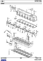
Cylinder head NOTE! Tighten the screws in number order, as in the illustration. Stage 1 ............................................................... 60 ±10 Nm (44±7 lbf-ft) Stage 2 (check tightening) .................................. 60 ±10 Nm (44±7 lbf-ft) Stage 3 ............................................................... 120° ± 5° angle tightening Stage 4 ............................................................... 90° ±5° angle tightening Core plugs, cylinder head ....................................... 60 ±10 Nm (44±7 lbf-ft) Lock nut, valve adjustment screw .......................... 60 ±5 Nm (44±4 lbf-ft)
30
Group 20
Group 20
Technical data
Bearing caps, camshaft / rocker arm shaft NOTE! Tighten the screws in stages, to ensure that the rocker arm shaft comes down without being bent. Stage 1: Torque screws 1-7 to ............................... 15 ±3 Nm (11±2 lbf-ft) Stage 2: Torque screws 9, 11, 13. ......................... 60 ±5 Nm (44±4 lbf-ft) Start with screw 11. Stage 3: Torque screws 8, 10, 12, 14. ................... 60 ±5 Nm (44±4 lbf-ft) Stage 4: Loosen screws 9, 11, 13. ......................... – Stage 5: Torque screws 9, 11, 13. ......................... 60 ±5 Nm (44±4 lbf-ft) Stage 6: Tighten screws 1-7. ................................. 90° ±5° angle tightening Stage 7: Tighten screws 8-14. ............................... 120° ±5° angle tightening
31
Technical data
Apply silicone sealer to the rear edge of the cylinder head and the engine block.
Group 20
Tighten the screws in number order.
Timing gear plate ......................................... 24 ±4 Nm (13±3 lbf-ft) NOTE! Apply silicone sealer and tighten the screws in number order, as in the illustration.
Timing gear cover, upper ............................ 24 ±4 Nm (13±3 lbf-ft) NOTE! Apply 2 mm (0,07874") silicone sealer as in the illustration.
32
Group 20
Technical data
Timing 1 Drive gear, crankshaft ............................................................. 24 ±4 Nm (13±3 lbf-ft) 2 Idler wheel, double gear Apply thread locking fluid 1161053 to the screws and tighten them in number order, as in the illustration. Stage 1 ..................................................................................... 35 ±4 Nm (26±3 lbf-ft) Stage 2 ..................................................................................... 60° ±5° angle tightening 3 Idler wheel, adjustable Tighten the screws in number order, as in the illustration. Stage 1 ..................................................................................... 35 ±4 Nm (26±3 lbf-ft) Stage 2 ..................................................................................... 120° ±5° angle tightening 4 Drive gear, camshaft Tighten the screws in number order, as in the illustration. Stage 1 ..................................................................................... 45 ±5 Nm (33±4 lbf-ft) Stage 2 ..................................................................................... 90° ±5° angle tightening 5 Drive wheel, steering servo and fuel feed pump ................... 100 ±10 Nm (74±7 lbf-ft) 6 Drive wheel, air compressor ................................................... 200+50 -0 Nm(148-0±37 lbf-ft)
33
Technical data
Tightening torque group 22: Lubricating system Oil sump ................................................................ 24 ±4 Nm (18±3 lbf-ft) NOTE! Tighten the screws in sequence, from the center and outwards. Drain plug, oil sump ............................................... 60 ±5 Nm (44±4 lbf-ft) Bracket, oil pump/main bearing caps ..................... 24 ±4 Nm (13±3 lbf-ft) Oil strainer, retaining screws .................................. 24 ±4 Nm (18±3 lbf-ft) Oil cooler, retaining screws .................................... 27 ±4 Nm (18±3 lbf-ft)
Tightening torque group 23: Fuel system Feed pump - steering servo pump .......................... 24 ±4 Nm (18±3 lbf-ft) Fixing yoke, unit injector (new copper sleeve) First tightening Stage 1 ............................................................... 20 ±5 Nm (15±4 lbf-ft) Stage 2 ............................................................... 180° ±5° angle tightening Loosen the fastening yoke screw before doing the second tightening. Second tightening Stage 1 ............................................................... 20 ±5 Nm (15±4 lbf-ft) Stage 2 ............................................................... 60° ±5° angle tightening Fixing yoke, unit injector (re-used copper sleeve) Stage 1 ............................................................... 20 ±5 Nm (14±3 lbf-ft) Stage 2 ............................................................... 60° ±5° angle tightening Locknut for rocker adjuster screw, unit injector Stage 1 ............................................................... tighten until contact Stage 2 .............................................................. 45° ±5° angle tightening Hollow screw M16 x 1.5 ......................................... 50 ±8 Nm Hollow screw M10 x 1 ............................................ 25 ±4 Nm
34
Group 20
Group 20
Technical data
Tightening tourqe group 25, Intake and exhaust system
Inlet pipe ......................................................... 24 ±4 Nm (18±3 lbf-ft) NOTE! Apply 2mm silicone sealer as in the illustration. Plug, M10 .............................................................. 20 ±3 Nm (15±3 lbf-ft) Pressure/temperature sensor, charge air ................ 12 ±2 Nm (9±2 lbf-ft)
Exhaust collector pipe Stage 1: Tighten the screws until they just touch ...................... 5 ±1.5 Nm (4±1 lbf-ft) Stage 2: Torque screws 1 and 8 ................................................ 10 ±1.5 Nm (7±1 lbf-ft) Stage 3: Torque screws 3 and 10 .............................................. 10 ±1.5 Nm (7±1 lbf-ft) Stage 4: Torque screws 5 and 12 .............................................. 10 ±1.5 Nm (7±1 lbf-ft) Stage 5: Torque screws 2 and 7 ................................................ 48 ±8 Nm (35±6 lbf-ft) Stage 6: Torque screws 4 and 9 ................................................ 48 ±8 Nm (35±6 lbf-ft) Stage 7: Torque screws 6 and 11 .............................................. 48 ±8 Nm (35±2 lbf-ft) Stage 8: Torque screws 1 and 8 ................................................ 48 ±8 Nm (35±2 lbf-ft) Stage 9: Torque screws 3 and 10 .............................................. 48 ±8 Nm (35±2 lbf-ft) Stage 10: Torque screws 5 and 12 ............................................ 48 ±8 Nm (35±2 lbf-ft)
35
Group 20
Reference to Service bulletins Group
No
Date
Refers to
......................................................................................................................................................................................... ......................................................................................................................................................................................... ......................................................................................................................................................................................... ......................................................................................................................................................................................... ......................................................................................................................................................................................... ......................................................................................................................................................................................... ......................................................................................................................................................................................... ......................................................................................................................................................................................... ......................................................................................................................................................................................... ......................................................................................................................................................................................... ......................................................................................................................................................................................... ......................................................................................................................................................................................... ......................................................................................................................................................................................... ......................................................................................................................................................................................... ......................................................................................................................................................................................... ......................................................................................................................................................................................... ......................................................................................................................................................................................... ......................................................................................................................................................................................... ......................................................................................................................................................................................... ......................................................................................................................................................................................... ......................................................................................................................................................................................... ......................................................................................................................................................................................... ......................................................................................................................................................................................... ......................................................................................................................................................................................... ......................................................................................................................................................................................... ......................................................................................................................................................................................... ......................................................................................................................................................................................... ......................................................................................................................................................................................... ......................................................................................................................................................................................... ......................................................................................................................................................................................... ......................................................................................................................................................................................... ......................................................................................................................................................................................... ......................................................................................................................................................................................... .........................................................................................................................................................................................
36
Notes ........................................................................................................................................................................................... ........................................................................................................................................................................................... ........................................................................................................................................................................................... ........................................................................................................................................................................................... ........................................................................................................................................................................................... ........................................................................................................................................................................................... ........................................................................................................................................................................................... ........................................................................................................................................................................................... ........................................................................................................................................................................................... ........................................................................................................................................................................................... ........................................................................................................................................................................................... ........................................................................................................................................................................................... ........................................................................................................................................................................................... ........................................................................................................................................................................................... ........................................................................................................................................................................................... ........................................................................................................................................................................................... ........................................................................................................................................................................................... ........................................................................................................................................................................................... ........................................................................................................................................................................................... ........................................................................................................................................................................................... ........................................................................................................................................................................................... ........................................................................................................................................................................................... ........................................................................................................................................................................................... ........................................................................................................................................................................................... ........................................................................................................................................................................................... ...........................................................................................................................................................................................
Notes ........................................................................................................................................................................................... ........................................................................................................................................................................................... ........................................................................................................................................................................................... ........................................................................................................................................................................................... ........................................................................................................................................................................................... ........................................................................................................................................................................................... ........................................................................................................................................................................................... ........................................................................................................................................................................................... ........................................................................................................................................................................................... ........................................................................................................................................................................................... ........................................................................................................................................................................................... ........................................................................................................................................................................................... ........................................................................................................................................................................................... ........................................................................................................................................................................................... ........................................................................................................................................................................................... ........................................................................................................................................................................................... ........................................................................................................................................................................................... ........................................................................................................................................................................................... ........................................................................................................................................................................................... ........................................................................................................................................................................................... ........................................................................................................................................................................................... ........................................................................................................................................................................................... ........................................................................................................................................................................................... ........................................................................................................................................................................................... ........................................................................................................................................................................................... ...........................................................................................................................................................................................
Report form Do you have any complaints or other comments about this manual. Please make a copy of this page, write your comments down and send them to us. The address is at the bottom. We would prefer you to write in English or Swedish.
From: ...................................................................... ................................................................................ ................................................................................ ................................................................................
Refers to publication: ................................................................................................................................ Publication No.: .................................. Date of issue: ................................................................................
Proposal/motivation: ................................................................................................................................. ................................................................................................................................................................. ................................................................................................................................................................. ................................................................................................................................................................. ................................................................................................................................................................. ................................................................................................................................................................. ................................................................................................................................................................. ................................................................................................................................................................. .................................................................................................................................................................
Date: .................................................................................. Signed: ..............................................................................
AB Volvo Penta Technical Information Dept. 42200 SE-405 08 Göteborg Sweden
7745342 English 07–2009