Wiring Diagram Volvo Engine [PDF]
Workshop Manual I Group 30 Electrical system 5(0) 9L, 12L, 13L, 16L Industrial Engines (EMS 2) Table of Content Ge
44 0 9MB
Papiere empfehlen


![Wiring Diagram Volvo Engine [PDF]](https://vdoc.tips/img/200x200/wiring-diagram-volvo-engine.jpg)
- Author / Uploaded
- diah131
Datei wird geladen, bitte warten...
Zitiervorschau
Workshop Manual
I
Group 30 Electrical system
5(0)
9L, 12L, 13L, 16L Industrial Engines (EMS 2)
Table of Content General Information 00-0 General ............................................................................................. 2
Specifications 03-3 Specifications, Electrical ................................................................ 7 Electrical System ................................................................................. 7 Engine Protection Map ........................................................................ 9
Safety and Other Instructions 05-1 Safety Instructions ........................................................................ 27
Special tools 08-2 Special Service Tools ................................................................... 31
General, Complete Vehicle Software 30-0 General ........................................................................................... 32 Design and Function ......................................................................... 32 30-2 Fault Tracing ................................................................................. 64 General ................................................................................................ 64 Fault Codes ........................................................................................ 66 Measurements .................................................................................. 146 VODIA Log Parameters ................................................................... 194
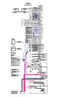
Cables and fuses 37-0 Wiring Diagrams ......................................................................... 195
Miscellaneous 39-0 General ......................................................................................... 227 Index ......................................................................................................... 229 References to Service Bulletins ............................................................ 231
47701632 06-2018 © AB VOLVO PENTA
1
00-0 General About this Workshop manual General information
Certified engines
This Service Manual contains technical data, descriptions and maintenance and repair instructions for standard model Volvo Penta products. A list of these products may be found in the section Specifications.
When carrying out service and repair on emission-certified engines, it is important to be aware of the following:
The product designation and the serial number and specification is indicated on the engine decal or type plate. This information must be included in all correspondence regarding the product. The service manual is produced primarily for the use of Volvo Penta workshops and their qualified personnel. It is assumed that any person using the Service Manual has a fundamental knowledge of the product and is able to carry out mechanical and electrical work to trade standard. Volvo Penta continually develops its products; we therefore reserve the right to make changes. All information in this manual is based on product data which was available up to the date on which the manual was printed. New working methods and significant changes introduced to the product after this date are communicated in the form of Service bulletins.
Spare Parts Spare parts for the electrical and fuel systems are subject to various national safety standards. Volvo Penta Original Spare Parts meet these standards. No damage of any kind caused by the use of spare parts not approved by Volvo Penta will be compensated by any warranty undertaking.
Certification means that an engine type has been inspected and approved by the relevant authority. The engine manufacturer guarantees that all engines of the same type are manufactured to correspond to the certified engine. This places special demands on service and repair work, namely: •
Maintenance and service intervals recommended by Volvo Penta must be complied with.
•
Only spare parts approved by Volvo Penta may be used.
•
Service on injection pumps, pump settings and injectors must always be carried out by an authorized Volvo Penta workshop.
•
The engine must not be converted or modified, except with accessories and service kits which Volvo Penta has approved for the engine.
•
No changes to the exhaust pipe and engine air inlet duct installations may be made.
•
No warranty seals (where present on the product) may be broken by unauthorized persons.
The general instructions in the Operator's Manual concerning operation, service and maintenance apply. IMPORTANT! Neglected or poorly-performed care/service and the use of spare parts not approved by Volvo Penta, will mean that AB Volvo Penta no longer guarantees that the engine conforms to the certified model. Volvo Penta accepts no responsibility for damage or costs arising as a result of failure to follow the above mentioned standards.
2
47701632 06-2018 © AB VOLVO PENTA
00-0 General
Repair instructions Introduction
Our mutual responsibility
The working methods described in this manual are based on a workshop scenario where the product is mounted in a holding fixture. Maintenance work is often carried out on site, in which case – if nothing else is indicated – using the same working methods as the workshop.
Each product comprises a large number of interacting systems and components. A deviation from the technical specification may dramatically increase the environmental impact of an otherwise reliable system. It is therefore critical that the stated wear tolerances be adhered to, that systems which can be adjusted be correctly set up and that only Volvo Penta Original Parts are used. The intervals in the care and maintenance schedule must be followed. Some systems, e.g. fuel systems, often require special expertise and test equipment. A number of components are factory-sealed, for among other things environmental reasons. Warranty-sealed components may not be worked on without authorization to perform such work.
Warning symbols that occur in the service manual. For significance, refer to Safety Information .
! ! !
DANGER! WARNING! CAUTION!
IMPORTANT!, NOTICE! are by no means comprehensive since not everything can be foreseen as service work is carried out in the most varied of circumstances. We call attention to risks that may occur due to incorrect handling during work in a well-equipped workshop using working methods and tools tried and tested by us. The service manual describes work operations carried out with the aid of Volvo Penta Special Tools, where such have been developed. Volvo Penta Special Tools are designed to ensure the safest and most rational working methods possible. It is therefore the responsibility of anyone using tools or working methods other than those we recommend to ensure that no risk of personal injury or mechanical damage is present, or that malfunction can result. In some cases, special safety regulations and user instructions may be in force for the tools and chemicals mentioned in the Service Manual. These regulations must always be followed, and no special instructions regarding this are to be found in the Service Manual. By taking these basic precautions and using common sense it will be possible to guard against most elements of risk. A clean workplace and a clean product will eliminate many risks of personal injury and malfunction. Above all, when working on fuel systems, hydraulic systems, lubrication systems, turbochargers, inlet systems, bearings and seals, it is of the utmost importance that dirt and foreign objects are kept away, as malfunctions or shortened service intervals may otherwise result.
47701632 06-2018 © AB VOLVO PENTA
Remember that most chemical products, incorrectly used, are harmful to the environment. Volvo Penta recommends the use of biodegradable degreasers whenever components are cleaned, unless otherwise specified in the Service Manual. When working outdoors, take especial care to ensure that oils and wash residues etc. are correctly properly for destruction.
Tightening torques Tightening torques for vital fasteners that must be applied using a torque wrench are indicated in the Service Manual, chapter Tightening torques and in the Manual's work descriptions. All torque indications apply to clean threads, bolt heads and mating faces. Indicated torque data apply to lightly-oiled or dry threads. If lubricants, locking fluids or sealants are required for fasteners, the correct type will be noted in the job description.
Torque, angle tightening When torque/angle tightening, the fastener is tightened to a specified torque, and tightening then continues through a pre-determined angle. Example: For 90° angle tightening, the fastener is turned a further 1/4 turn in one sequence, after the specified tightening torque has been achieved.
3
00-0 General
Lock nuts Removed locknuts may not be re-used; they must be replaced by new ones, as locking properties are impaired or lost with re-use. In the case of lock nuts with plastic inserts the tightening torque indicated must be reduced if the nut has the same nut height as a standard, all-metal hexagonal nut. Reduce the torque by 25% for bolt sizes of 8 mm or larger. In the case of lock nuts with plastic inserts with a high nut-height (where the all-metal thread is as high as a standard hexagonal nut), the indicated torque applies.
Strength classes Nuts and bolts are subdivided into different strength classes. The classification is shown by a marking on the bolt head. Markings of a higher number indicate stronger material. For example, a bolt marked 10-9 is stronger than one marked 8-8. For this reason, it is important that when bolts are removed they are returned to their original locations on re-assembly. When replacing bolts check the applicable Spare parts catalogue to ensure the correct bolt is used.
Sealing compounds etc. To ensure service work is correctly carried out it is important that the correct type of sealants and locking fluids are used on joints where such are required. In each service manual section concerned, the sealants used in product manufacture are indicated. The same sealants, or sealants with equivalent properties, must be used for maintenance work. Make sure that mating surfaces are dry and free from oil, grease, paint and anti-corrosion agent before applying sealant or locking fluid. Always follow the manufacturer's instructions regarding applicable temperatures, hardening times and such. Two basic types of compound are used: RTV preparations (Room Temperature Vulcanizing). Used most often together with gaskets, e.g. sealing gasket joints, or are brushed on gaskets. RTV sealants are completely visible when the part has been removed. Old RTV sealant must be removed before the component is sealed again. Use denatured alcohol.
4
Anaerobic agents. These agents cure (harden) in the absence of air. These preparations are used when two solid components, e.g. two cast components, are fitted together without a gasket. Common uses are also to lock and seal plugs, stud threads, taps, oil pressure monitors etc. Hardened anaerobic preparations are glassy and for this reason, the preparations are colored to make them visible. Hardened anaerobic preparations are highly resistant to solvents, and old compound cannot be removed. On re-assembly, it is important to carefully degrease and wipe dry components first, before applying new sealant in accordance with the instructions.
Safety regulations for fluorocarbon rubber Fluorocarbon rubber is a common material in sealing rings for shafts, and in O-rings, for example. When fluorocarbon rubber is exposed to high temperatures (above 300°C/572°F), hydrofluoric acid can form. This is highly corrosive. Contact with the skin can result in severe chemical burns. Splashes in your eyes can result in chemical wounds. If you breathe in the fumes, your lungs can be permanently damaged.
WARNING! Seals must never be cut with a torch, or be burnt afterwards in an uncontrolled manner. Risk for poisonous gases.
WARNING! Always use chloroprene rubber gloves (gloves for chemicals handling) and goggles. Handle the removed seal in the same way as corrosive acid. All residue, including ash, can be highly corrosive. Never use compressed air to blow clean. Put the remains in a plastic container, seal it and apply a warning label. Wash the gloves under running water before removing them. The following seals are most probably made from fluorocarbon rubber: Seal rings for the crankshaft, camshaft, idler shafts. O-rings, regardless of where they are installed. Orings for cylinder liner sealing are almost always made of fluorocarbon rubber. Please note that seals which have not been exposed to high temperature can be handled normally.
47701632 06-2018 © AB VOLVO PENTA
00-0 General
Repair instructions Introduction
Our Mutual Responsibility
The working methods described in this manual are based on a workshop scenario where the product is mounted in a workholding fixture. Maintenance work is often carried out in situ, in which case - if nothing else is indicated - using the same working methods as the workshop.
Each product comprises a large number of interacting systems and components. A deviation from the technical specification may dramatically increase the environmental impact of an otherwise reliable system. It is therefore critical that the stated wear tolerances be adhered to, that systems which can be adjusted be correctly set up and that only Volvo Penta Original Parts are used. The intervals in the care and maintenance schedule must be followed. Some systems, e.g. fuel systems, often require special expertise and test equipment. A number of components are factory-sealed, for among other things environmental reasons. Warranty-sealed components may not be worked on without authorization to perform such work.
Warning symbols that occur in the service manual. For significance, refer to Safety Information.
DANGER! WARNING! CAUTION! IMPORTANT!, NOTE! are by no means comprehensive since not everything can be foreseen as service work is carried out in the most varied of circumstances. We call attention to risks that may occur due to incorrect handling during work in a well-equipped workshop using working methods and tools tried and tested by us. The service manual describes work operations carried out with the aid of Volvo Penta Special Tools, where such have been developed. Volvo Penta Special Tools are designed to ensure the safest and most rational working methods possible. It is therefore the responsibility of anyone using tools or working methods other than those we recommend to ensure that no risk of personal injury or mechanical damage is present, or that malfunction can result. In some cases, special safety regulations and user instructions may be in force for the tools and chemicals mentioned in the Service Manual. These rules must always be observed, so there are no special instructions about this in the workshop manual. By following these basic recommendations and using common sense it is possible to avoid most of the risks involved in the work. A clean workplace and a clean product will eliminate many risks of personal injury and malfunction.
Remember that most chemical products, incorrectly used, are harmful to the environment. Volvo Penta recommends the use of biodegradable degreasers whenever components are cleaned, unless otherwise specified in the Service Manual. When working outdoors, take especial care to ensure that oils and wash residues etc. are correctly properly for destruction.
Tightening torque Tightening torques for vital fasteners that must be applied using a torque wrench are indicated in the Service Manual, chapter Tightening torques and in the Manual's work descriptions. All torque indications apply to clean threads, bolt heads and mating faces. Indicated torque data apply to lightly-oiled or dry threads. If lubricants, locking fluids or sealants are required for fasteners, the correct type will be indicated in the job description.
Torque, angle tightening When torque/angle tightening, the fastener is tightened to a specified torque, and tightening then continues through a pre-determined angle. Example: For 90° angle tightening, the fastener is turned an additional 1/4 turn in one sequence, after the specified tightening torque has been achieved.
Above all, when working on fuel systems, hydraulic systems, lubrication systems, turbochargers, inlet systems, bearings and seals, it is of the utmost importance that dirt and foreign objects are kept away, as malfunctions or shortened service intervals may otherwise result.
47701632 06-2018 © AB VOLVO PENTA
5
00-0 General
Lock nuts Removed lock nuts may not be re-used; they must be replaced by new ones, as locking properties are impaired or lost with re-use. In the case of lock nuts with plastic inserts, the tightening torque indicated must be reduced if the nut has the same nut height as a standard, all-metal hexagonal nut. Reduce the torque by 25% for bolt sizes of 8 mm or larger. In the case of lock nuts with plastic inserts with a high nut-height (where the all-metal thread is as high as a standard hexagonal nut), the indicated torque applies.
Strength Classes Nuts and bolts are grouped into different strength classes. Their classification is shown by a marking on the bolt head. Markings of a higher number indicate stronger material. For example, a bolt marked 10-9 is stronger than one marked 8-8. For this reason, it is important that when bolted joints are removed they are returned to their original locations on re-assembly. When replacing bolts, check the applicable Spare parts catalog to ensure the correct bolt is used.
Sealing compounds etc. To ensure service work is correctly carried out, it is important that the correct type of sealants and locking fluids are used on joints where such are required. In each service manual section concerned, the sealants used in product manufacture are indicated. The same sealants, or sealants with equivalent properties, must be used for maintenance work. A service technician should have a basic knowledge of how sealing compounds are handled, and are able to assess the condition of existing seals. Make sure that mating surfaces are dry and free from oil, grease, paint and anti-corrosion agent before applying sealant or locking fluid. Always follow the manufacturer's instructions regarding applicable temperatures, hardening times and such. Two basic types of compound are used: RTV preparations (Room Temperature Vulcanizing). Used most often together with gaskets, e.g. sealing gasket joints, or are brushed on gaskets. RTV sealants are completely visible when the part has been removed. Old RTV sealant must be removed before the component is sealed again. Use denatured alcohol.
6
Anaerobic agents. These agents cure in the absence of air. These preparations are used when two solid components, e.g. two cast components, are fitted together without a gasket. Common uses are also to lock and seal plugs, stud threads, taps, oil pressure monitors etc. Hardened anaerobic preparations are vitreous and for this reason, the preparations are colored to make them visible. Hardened anaerobic preparations are highly resistant to solvents, and old compound cannot be removed. On re-assembly, it is important to carefully degrease and wipe dry components first, before applying new sealant in accordance with the instructions.
Safety regulations for fluorocarbon rubber Fluorocarbon rubber is a common material in seal rings for shafts, and in O-rings, for example. When fluorocarbon rubber is exposed to high temperatures (above 300°C/572°F), hydrofluoric acid can form. This is highly corrosive. Contact with the skin can result in severe chemical burns. Splashes in your eyes can result in corrosive wounds. If you breathe in the fumes, your lungs can be permanently damaged.
WARNING! Seals must never be cut with a torch, or be burnt afterwards in an uncontrolled manner. Risk for poisonous gases.
WARNING! Always use chloroprene rubber gloves (gloves for chemicals handling) and goggles. Handle the removed seal in the same way as corrosive acid. All residue, including ash, can be highly corrosive. Never use compressed air to blow clean. Put the remains in a plastic container, seal it and apply a warning label. Wash the gloves under running water before removing them. The following seals are most probably made from fluorocarbon rubber: Seal rings for the crankshaft, camshaft, idler shafts. O-rings, regardless of where they are installed. Orings for cylinder liner sealing are almost always made of fluorocarbon rubber. Please note that seals which have not been exposed to high temperature can be handled normally.
47701632 06-2018 © AB VOLVO PENTA
03-3 Specifications, Electrical
03-3 Specifications, Electrical Electrical System Technical Data Switch, water in fuel Voltage
24 V
Connector
2 pin
Contact type
Closes when water is detected
Sensor, fuel pressure Voltage
5V
Connector
3 pin
Working pressure range
0–700 kPa (0-7 bar) (0–101.5 PSI)
Pressure signal
0.5–4.5 V
Working temperature range
-40 °C to +140 °C
Type
Linear
Max tightening torque
30 ±5 Nm (22 ±3.7 lbf.ft.)
Speed sensor, crankshaft / camshaft Connector
2 pin
Working temperature range
-40 °C to +130 °C (-40 °F to +262 °F)
Type
Inductive sensor
Max. tightening torque
8 ±2 Nm (5.9 ±1.48 lbf.ft.)
Sensor, oil pressure Voltage
5V
Connector
3 pin
Working pressure range
0–700 kPa (0-7 bar) (0–101.5 kPa)
Pressure signal
0.5–4.5 V
Working temperature range
-40 °C to +140 °C (-40 °F to +284 °F)
Type
Linear
Max tightening tourque
30 ±5 Nm (22 ±3.7 lbf.ft.)
Combination sensor, air inlet pressure / inlet manifold temperature Voltage
5V
Connector
4 pin
Working pressure range
50–400 kPa (0.5-4 bar) (7.3–58.0 PSI)
Pressure signal
0.5–4.5 V
Working temperature range
-40 °C to +130 °C (-40 °F to +262 °F)
Type
Linear/NTC
Sensor, coolant temperature Voltage
5V
Connector
2 pin
47701632 06-2018 © AB VOLVO PENTA
7
03-3 Specifications, Electrical Type
NTC
Max. tightening torque
25 Nm (18.4 lbf.ft.)
Switch, coolant level Connector
2 pin
Contact type
Closing with low coolant level
Alternator Voltage
24 V
Connector
2 pin
Capacity
80 A at 24 V
Starter motor Voltage
12 V
Connector
1 pol
Capacity (TAD1341–1345)
5.5 kW (7 kW)
Sensor, crankcase pressure Voltage
5V
Connector
3 pin
Working pressure range
40–140 kPa (0.4–1.4 bar) (5.8–20.3 PSI)
Pressure signal
0.5–4.5 V
Working temperature range
-40 °C to +140 °C (-40 °F to +284 °F)
Type
Linear
Combination sensor, oil level / temperature Voltage
5V
Connector
4 pin
Working temperature range
-40 °C to +140 °C (-40 °F to +284 °F)
Type
NTC
Switch, piston cooling pressure Connector
2 pin
Contact type
Closing for low piston cooling pressure
Combination sensor, air filter pressure/temperature Voltage
Max 24 V
Connector
4 pin
Switch point
-5 ±0.5 kPa (-50 ±5 mbar) (-0.73 ±0.073 PSI)
Working temperature range
-40 °C to +100 °C (-40 °F to +244 °F)
Type
NTC
8
47701632 06-2018 © AB VOLVO PENTA
03-3 Specifications, Electrical
Engine Protection Map Engine protection maps are not updated. For the latest version, please refer to the Volvo Penta Sales Support Tool, Technical data for concerned engine type. TAD940VE, TAD941VE, TAD942VE, TAD943VE Parameter
Alarm
Engine protection
Setting range
Default setting
Derating level
Action
120-130 °C (248-266 °F)
125 °C (257 °F)
Setting +3 °C (5.4 °F)
Torque reduction(1) / Shutdown(2)
Low idle
NA
160 kPa (23.2 psi)
130 kPa (18.9 psi)
Torque reduction(1) / Shutdown(2)
Rated speed
NA
225 kPa (32.6 psi)
195 kPa (28.3 psi)
Torque reduction(1) / Shutdown(2)
Oil level
NA
Low level
NA
NA
Piston cooling pressure, >1000 rpm
NA
NA
NA
NA
95-101 °C (203-213.8 °F)
98 °C (208.4 °F)
Setting +7 °C (12.6 °F)
Torque reduction(1) / Shutdown(2)
-
On
Low level
Torque reduction(1) / Shutdown(2)
NA
100 kPa (14.5 psi)
NA
NA
Water in Fuel
Water present
NA
NA
NA
Crankcase pressure
Rapid pressure increase
-
-
Torque reduction(1) / Shutdown(2)
Air filter pressure droop
NA
NA
NA
NA
Altitude, above sea
NA
NA
1200 m (1312 yds)
Automatic derating
Intake manifold temperature
NA
80 °C (176 °F)
91 °C (195.8 °F)
Torque reduction(1) / Shutdown(2)
Air inlet pressure
NA
325 kPa (47.1 psi)
350 kPa (50.8 psi)
Torque reduction(1) / Shutdown(2)
100-120 % of rated speed
115 % of rated speed
Alarm level
NA
Oil temperature Oil pressure
Coolant temperature Coolant Level Fuel feed pressure
Engine Speed
Low idle
1. Versatile. 2. Power Pack
47701632 06-2018 © AB VOLVO PENTA
9
03-3 Specifications, Electrical TAD950VE, TAD951VE, TAD952VE Parameter
Alarm
Engine protection
Setting range
Default setting
Derating level
Action
120-130 °C (248-266 °F)
125 °C (257 °F)
Setting +3 °C (5.4 °F)
Torque reduction
Low idle
NA
160 kPa (23.2 psi)
140 kPa (20.3 psi)
Torque reduction
Rated speed
NA
200 kPa (29.0 psi)
180 kPa (26.1 psi)
Torque reduction
Oil level
NA
Low level
NA
NA
Piston cooling pressure, >1000 rpm
NA
NA
NA
Torque reduction
95-101 °C (203-213.8 °F)
98 °C (208.4 °F)
Setting +3 °C (5.4 °F)
Torque reduction
-
On
Low level
Torque reduction
NA
100 kPa (14.5 psi)
NA
NA
Water in Fuel
Water present
NA
NA
NA
Crankcase pressure
Rapid pressure increase
-
-
Torque reduction
Air filter pressure droop
NA
NA
NA
NA
Altitude, above sea
NA
NA
1200 m (1312 yds)
Automatic derating
Intake manifold temperature
NA
80 °C (176 °F)
91 °C (195.8 °F)
Torque reduction
Air inlet pressure
NA
325 kPa (47.1 psi)
350 kPa (50.8 psi)
Torque reduction
100-120 % of rated speed
115 % of rated speed
Alarm level
Shutdown. On/Off(1)
Oil temperature Oil pressure
Coolant temperature Coolant Level Fuel feed pressure
Engine Speed
Low idle
1. Off = No shutdown, alarm only.
10
47701632 06-2018 © AB VOLVO PENTA
03-3 Specifications, Electrical TAD940GE, TAD941GE Parameter
Alarm
Engine protection
Setting range
Default setting
Derating level
Action
120-130 °C (248-266 °F)
125 °C (257 °F)
Setting +3 (5.4 °F)
Shutdown. On/Off
Low idle
NA
160 kPa (23.2 psi)
130 kPa (18.9 psi)
Shutdown. On/Off
1500 rpm
NA
250 kPa (36.3 psi)
220 kPa (31.9 psi)
Shutdown. On/Off
1800 rpm
NA
300 kPa (43.5 psi)
270 kPa (39.2 psi)
Shutdown. On/Off
Oil level
NA
Low level
NA
NA
Piston cooling pressure, >1000 rpm
NA
NA
NA
NA
95-103 °C (203-217.4 °F)
98 °C (208.4 °F)
Setting +5 (9 °F)
Shutdown. On/Off
NA
Low level
Low level
Shutdown. On/Off
Low idle
NA
150 kPa (21.8 psi)
NA
NA
>1400 rpm
NA
300 kPa (43.5 psi)
NA
NA
Water in Fuel
NA
Water in Fuel
NA
NA
Crankcase pressure
NA
Increased pressure
Increased pressure
Shutdown. On/Off
Air filter pressure droop
NA
NA
NA
NA
Altitude, above sea
NA
-
>1500 m (>1640 yds)
Automatic derating
Intake manifold temperature
NA
87 °C (188.6 °F)
92 °C (197.6 °F)
Shutdown. On/Off
Air inlet pressure
NA
380 kPa (55.1 psi)
380 kPa (55.1 psi)
Shutdown. On/Off
100-120 % of rated speed
120 % of rated speed
Alarm level
Shutdown. Off/On
Oil temperature Oil pressure
Coolant temperature Coolant Level Fuel feed pressure
Engine Speed
47701632 06-2018 © AB VOLVO PENTA
11
03-3 Specifications, Electrical TAD1250VE, TAD1251VE, TAD1252VE Parameter
Alarm
Engine protection
Setting range
Default setting
Derating level
Action
120-130 °C (248-266 °F)
125 °C (257 °F)
Setting +3 °C (5.4 °F)
Torque reduction
Low idle
-
160 kPa (23.2 psi)
130 kPa (18.9 psi)
Torque reduction
Rated speed
-
225 kPa (32.6 psi)
195 kPa (28.3 psi)
Torque reduction
Oil level
-
Min level
-
-
Piston cooling pressure, >1000 rpm
-
-
-
Torque reduction
95-101 °C (203-213.8 °F)
98 °C (208.4 °F)
Setting +7 °C (12.6 °F)
Torque reduction
-
On
Low level
Torque reduction
Low idle
-
100 kPa (14.5 psi)
-
-
Rated speed
-
300 kPa (43.5 psi)
-
-
-
High level
-
-
Rapid pressure increase
-
-
Torque reduction
Air filter pressure droop
-
5.0 kPa (0.7 psi)
-
-
Altitude, above sea
-
-
-
Automatic derating
Intake manifold temperature
-
80 °C (176 °F)
90 °C (194 °F)
Torque reduction
Air inlet pressure
-
325 kPa (47.1 psi)
350 kPa (50.8 psi)
Torque reduction
100-120 % of rated speed
115 % of rated speed
-
-
-
25,5 V
-
-
Oil temperature Oil pressure
Coolant temperature Coolant Level Fuel feed pressure
Water in Fuel Crankcase pressure
Engine Speed Low voltage
12
47701632 06-2018 © AB VOLVO PENTA
03-3 Specifications, Electrical TAD1341GE, TAD1342GE, TAD1343GE, TAD1344GE, TAD1345GE Parameter
Alarm
Engine protection
Setting range
Default setting
Derating level
Action
120-130 °C (248-266 °F)
125 °C (257 °F)
Setting +5 °C (9 °F)
Shutdown
Low idle
-
190 kPa (27.6 psi)
160 kPa (23.2 psi)
Shutdown
1500 rpm
-
250 kPa (36.3 psi)
220 kPa (31.9 psi)
Shutdown
1800 rpm
-
300 kPa (43.5 psi)
270 kPa (39.2 psi)
Shutdown
Oil level
-
Min level
-
-
Piston cooling pressure, >1000 rpm
-
150 kPa (21.8 psi)
150 kPa (21.8 psi)
Shutdown
95-103 °C (203-217.4 °F)
102 °C (215.6 °F)
Setting +5 °C (9 °F)
Shutdown
-
On
Low level
Shutdown
Low idle
-
100 kPa (14.5 psi)
-
-
>1400 rpm
-
200 kPa (29.0 psi)
-
-
Water in Fuel
-
High level
-
-
Crankcase pressure
-
Increased pressure
Increased pressure
Shutdown
Air filter pressure droop
-
5.0 kPa (0.7 psi)
-
-
Altitude, above sea
-
-
-
Automatic derating
Intake manifold temperature
-
80 °C (176 °F)
85 °C (185 °F)
Shutdown
Air inlet pressure
1500 rpm
-
360 kPa (52.2 psi)
370 kPa (53.7 psi)
Shutdown
1800 rpm
-
350 kPa (50.8 psi)
360 kPa (52.2 psi)
Shutdown
100-120 % of rated speed
120 % of rated speed
Alarm level
Shutdown
Oil temperature Oil pressure
Coolant temperature Coolant Level Fuel feed pressure
Engine Speed
Engine protection can be disabled. For consequences, see VP International Limited Warranty Policy.
47701632 06-2018 © AB VOLVO PENTA
13
03-3 Specifications, Electrical TAD1350GE Parameter
Alarm
Engine protection
Setting range
Default setting
Derating level
Action
120-130 °C (248-266 °F)
125 °C (257 °F)
Setting +5 °C (9 °F)
Shutdown / Off(1)
Low idle
-
150 kPa (21.8 psi)
120 kPa (17.4 psi)
Shutdown / Off(1)
1800 rpm
-
300 kPa (43.5 psi)
270 kPa (39.2 psi)
Shutdown / Off(1)
Oil level
-
Min level
-
-
Piston cooling pressure, >1000 rpm
-
150 kPa (21.8 psi)
150 kPa (21.8 psi)
Shutdown / Off(1)
95-103 °C (203-217.4 °F)
102 °C (215.6 °F)
Setting +5 °C (9 °F)
Shutdown / Off(1)
-
On
Low level
Shutdown / Off(1)
Low idle
-
100 kPa (14.5 psi)
-
-
>1400 rpm
-
300 kPa (43.5 psi)
-
-
Water in Fuel
-
High level
-
-
Crankcase pressure
-
Increased pressure
Increased pressure
Shutdown / Off(1)
Air filter pressure droop
-
5.0 kPa (0.7 psi)
-
-
Altitude, above sea
-
-
-
Automatic derating
Intake manifold temperature
-
80 °C (176 °F)
85 °C (185 °F)
Shutdown / Off(1)
Air inlet pressure
-
310 kPa (45.0 psi)
320 kPa (46.4 psi)
Shutdown / Off(1)
100-120 % of rated speed
120 % of rated speed
Alarm level
Shutdown / Off(1)
Oil temperature Oil pressure
Coolant temperature Coolant Level Fuel feed pressure
Engine Speed
1. Off = No shutdown, alarm only.
14
47701632 06-2018 © AB VOLVO PENTA
03-3 Specifications, Electrical TAD1351GE, TAD1352GE, TAD1353GE, TAD1354GE, TAD1355GE Parameter
Alarm
Engine protection
Setting range
Default setting
Derating level
Action
120-130 °C (248-266 °F)
125 °C (257 °F)
Setting +5 °C (9 °F)
Shutdown
Low idle
-
150 kPa (21.8 psi)
120 kPa (17.4 psi)
Shutdown
1500 rpm
-
250 kPa (36.3 psi)
220 kPa (31.9 psi)
Shutdown
1800 rpm
-
300 kPa (43.5 psi)
270 kPa (39.2 psi)
Shutdown
Oil level
-
Min level
-
-
Piston cooling pressure, >1000 rpm
-
150 kPa (21.8 psi)
150 kPa (21.8 psi)
Shutdown
95-103 °C (203-217.4 °F)
102 °C (215.6 °F)
Setting +5 °C (9 °F)
Shutdown
-
On
Low level
Shutdown
Low idle
-
150 kPa (21.8 psi)
-
-
>1400 rpm
-
300 kPa (43.5 psi)
-
-
Water in Fuel
-
High level
-
-
Crankcase pressure
-
Increased pressure
Increased pressure
Shutdown
Air filter pressure droop
-
5.0 kPa (0.7 psi)
-
-
Altitude, above sea
-
-
-
Automatic derating
Intake manifold temperature
-
80 °C (176 °F)
85 °C (185 °F)
Shutdown
Air inlet pressure
-
310 kPa (45.0 psi)
320 kPa (46.4 psi)
Shutdown
100-120 % of rated speed
120 % of rated speed
Alarm level
Shutdown
Oil temperature Oil pressure
Coolant temperature Coolant Level Fuel feed pressure
Engine Speed
Engine protection can be disabled. For consequences, see VP International Limited Warranty Policy.
47701632 06-2018 © AB VOLVO PENTA
15
03-3 Specifications, Electrical TAD1350VE Parameter
Signal
Parameter range
Alarm switch
Alarm level
50-0 kW
-40°–140 °C (-40–284 °F)
-
125 °C (257 °F)
130 °C (266 °F)
2s
100% of max torque
Oil level
-
-
-
Low level
N/A
30 s
-
Air inlet pressure
0.5-4.5 V
50-400 kPa (7.3-58 psi)
-
-
10 kPa above alarm level
2s
50% of max torque
Intake manifold temperature
50-0 kW
-40°–130 °C (-40–266 °F)
-
82 °C (179.6 °F)
87 °C (188.6 °F)
30 s
100% of max torque
Crankcase pressure
0.5-4.5 V
0-15 kPa (0-2.2 psi)
-
Rapid pressure increase
Rapid pressure increase
Instant
100% of max torque
Water in Fuel
Digital
-
Alarm when closed
Water in Fuel
N/A
5s
N/A
Coolant temperature
50-0 kW
-40°–140 °C (-40–284 °F)
-
102 °C (215.6 °F)
107 °C (224.6 °F)
2s
50% / °C of max torque
Coolant level
Digital
-
Alarm when closed
Low level
N/A
4s
N/A
Engine speed, camshaft
Frequency
-
-
Lost signal
-
Instant
-
Engine speed, crankshaft
Frequency
-
-
Lost signal
-
Instant
-
Oil temperature
Parameter
Signal
Parameter range
Fuel pressure
0.5-4.5 V
Warning level
-
-
Alarm level
-
-
Derating level Conditio n / delay
Engine Speed
0-700 kPa 600 rpm (0-101 psi)
Derating
Conditi on
Derating
1000 rpm
1200 rpm
1500 rpm
1900 rpm
-
-
0
100
150
200
200
5s
N/A
N/A
N/A
N/A
N/A
N/A
N/A
N/A
1000 rpm
1200 rpm
1500 rpm
1900 rpm
-
-
Oil pressure
0.5-4.5 V
Warning level
-
-
140
200
224
260
287
2s
-
Alarm level
-
-
115
175
199
235
262
Instant
70% of max torque in step of 10% / s
16
0-700 kPa 600 rpm (0-101 psi)
47701632 06-2018 © AB VOLVO PENTA
03-3 Specifications, Electrical TAD1340VE, TAD1341VE, TAD1342VE, TAD1343VE, TAD1344VE, TAD1345VE Parameter
Alarm
Engine protection
Setting range
Default setting
Derating level
Action
120-130 °C (248-266 °F)
125 °C (257 °F)
Setting +5 (9 °F)
Shutdown / Off(1)
Low idle
-
150 kPa (21.8 psi)
130 kPa (18.9 psi)
Shutdown / Off(1)
Rated speed
-
250 kPa (36.3 psi)
230 kPa (33.4 psi)
Shutdown / Off(1)
Oil level
-
Min level
-
-
Piston cooling pressure, >1000 rpm
-
150 kPa (21.8 psi)
150 kPa (21.8 psi)
Shutdown / Off(1)
95-102 °C (203-215.6 °F)
102 °C (215.6 °F)
Setting +5 (9 °F)
Shutdown / Off(1)
-
On
Low level
Shutdown / Off(1)
Low idle
-
100 kPa (14.5 psi)
-
-
>1300 rpm
-
300 kPa (43.5 psi)
-
-
Water in Fuel
-
High level
-
-
Crankcase pressure
-
-
Rapid pressure increase
Shutdown / Off(1)
Air filter pressure droop
-
5.0 kPa (0.7 psi)
-
-
Altitude, above sea
-
-
-
Automatic derating
Intake manifold temperature
-
80 °C (176 °F)
85 °C (185 °F)
Shutdown / Off(1)
Air inlet pressure(2)
-
310 kPa (45.0 psi)
320 kPa (46.4 psi)
Shutdown / Off(1)
100-120 % of rated speed
120 % of rated speed
Alarm level
-
Oil temperature Oil pressure
Coolant temperature Coolant Level Fuel feed pressure
Engine Speed
1. Off = No shutdown, alarm only. 2. Pabs, 2100 rpm at sea level.
47701632 06-2018 © AB VOLVO PENTA
17
03-3 Specifications, Electrical TAD1360VE, TAD1361VE, TAD1362VE, TAD1363VE, TAD1364VE, TAD1365VE, TAD1640VE-B, TAD1641VE-B, TAD1642VE-B, TAD1660VE, TAD1661VE, TAD1662VE Parameter
Warning level
Alarm level
Engine protection
Parameter for Power Pack
Default setting
Level
Action. Default / Alternative
Oil temperature
125 °C (257 °F)
Setting +5 °C (9 °F)
Shutdown. On/Off(1)
50 kPa (7.3 psi)
25 kPa (3.6 psi)
Shutdown. On/Off(1)
300 kPa (43.5 psi)
275 kPa (39.9 psi)
Shutdown. On/Off(1)
Min level
-
-
105 °C (221 °F)
107 °C (224.6 °F)
Shutdown. On/Off(1)
Low level
-
-
Low idle
-
100 kPa (14.5 psi)
-
1200 rpm
-
250 kPa (36.3 psi)
-
High level
-
-
Increased pressure
-
Shutdown. On/Off(1)
5.0 kPa (0.7 psi)
-
-
-
-
Automatic derating
80 °C (176 °F)
85 °C (185 °F)
Shutdown. On/Off(1)
Warning map value + 5 kPa (0.7 psi)
Alarm map value + 5 kPa (0.7 psi)
Shutdown. On/Off(1)
120 %
-
Shutdown. On/Off(1)
Oil pressure
Low idle Rated speed
Oil level Coolant temperature Coolant Level Fuel feed pressure Water in Fuel Crankcase pressure Air filter pressure droop Altitude, above sea Intake manifold temperature Air inlet pressure Engine Speed
1. Off = Disables the function, i.e. no shutdown.
18
47701632 06-2018 © AB VOLVO PENTA
03-3 Specifications, Electrical
Parameter
Warning level
Alarm level
Parameter for Mobile
Warning
Alarm
Oil temperature
Engine protection Derate to eng. prot. map 0%
100 %
Forced shutdown after 2 sec
125 °C (257 °F)
127 °C (260.6 °F)
127 °C (260.6 °F)
130 °C (266 °F)
N/A
Warning map value
Alarm map value
N/A
N/A
Alarm map value
Oil level
Min level
N/A
N/A
N/A
N/A
Coolant temperature
105 °C (221 °F)
107 °C (224.6 °F)
107 °C (224.6 °F)
108 °C (226.4 °F)
N/A
Coolant Level
Low level
N/A
N/A
N/A
N/A
Warning map value
N/A
N/A
N/A
N/A
High level
N/A
N/A
N/A
N/A
N/A
Increased pressure 5.0 kPa (0.7 psi)
N/A
N/A
Increased pressure 5.0 kPa (0.7 psi)
Air filter pressure droop
-
5.0 kPa (0.7 psi)
N/A
N/A
N/A
Altitude, above sea
-
-
-
-
Automatic derating
80 °C (176 °F)
85 °C (185 °F)
85 °C (185 °F)
86 °C (186.8 °F)
N/A
Warning map value
Alarm map value
Alarm map value
Alarm map value
N/A
120 %
N/A
N/A
N/A
N/A
Oil pressure
Fuel feed pressure Water in Fuel Crankcase pressure
Intake manifold temperature Air inlet pressure Engine Speed
47701632 06-2018 © AB VOLVO PENTA
19
03-3 Specifications, Electrical TAD1641VE, TAD1642VE, TAD1643VE Parameter
Alarm
Engine protection
Setting range
Default setting
Derating level
Action
120-130 °C (248-266 °F)
125 °C (257 °F)
Setting +5 (9 °F)
Shutdown / Off(1)
Low idle
-
160 kPa (23.2 psi)
130 kPa (18.9 psi)
Shutdown / Off(1)
Rated speed
-
300 kPa (43.5 psi)
270 kPa (39.2 psi)
Shutdown / Off(1)
Oil level
-
Min level
-
-
Piston cooling pressure, >1000 rpm
-
150 kPa (21.8 psi)
150 kPa (21.8 psi)
Shutdown / Off(1)
95-101 °C (203-213.8 °F)
98 °C (208.4 °F)
Setting +5 (9 °F)
Shutdown / Off(1)
-
On
Low level
Shutdown / Off(1)
Low idle
-
100 kPa (14.5 psi)
-
-
Rated speed
-
300 kPa (43.5 psi)
-
-
Water in Fuel
-
High level
-
-
Crankcase pressure
-
-
-
Shutdown
Air filter pressure droop
-
5.0 kPa (0.7 psi)
-
-
Altitude, above sea
-
-
-
Automatic derating
Intake manifold temperature
-
80 °C (176 °F)
85 °C (185 °F)
Shutdown
Air inlet pressure
-
290 kPa (42.1 psi)
340 kPa (49.3 psi)
Shutdown
100-120 % of rated speed
120 % / Off(1)
Alarm level
Shutdown / On
-
25.5 V
-
-
Oil temperature Oil pressure
Coolant temperature Coolant Level Fuel feed pressure
Engine Speed Low voltage
1. Off = No shutdown, alarm only.
20
47701632 06-2018 © AB VOLVO PENTA
03-3 Specifications, Electrical TAD1650VE Parameter
“Yellow lamp”
“Red lamp”
Derate 0 % to Derate 70 % Forced eng. prot. map to eng. idle after prot. map 5 sec
Forced shutdown after 15 sec
Coolant temperature
98 °C 101 °C (208.4 °F) (213.8 °F)
101 °C (213.8 °F)
106 °C (222.8 °F)
>106 °C (222.8 °F)
>106 °C (222.8 °F)
Oil temperature
125 °C 128 °C (257.0 °F) (262.4 °F)
128 °C (262.4 °F)
135 °C (275.0 °F)
-
-
High inlet manifold temperature
80 °C 83 °C (176.0 °F) (181.4 °F)
83 °C (181.4 °F)
90 °C (194 °F)
>90 °C (194 °F)
>90 °C (194 °F)
Parameter
“Yellow lamp”
High air inlet pressure
30 kPa > demand (4.4 psi)
Parameter
“Yellow lamp”
“Red lamp” Derate 50 % to eng. Forced idle prot. map after 5 sec 40 kPa > demand (5.8 psi)
40 kPa > demand (5.8 psi)
45 kPa > demand (6.5 psi)
“Red lamp” Derate 70 % to eng. Forced idle prot. map after 5 sec
Forced shutdown after 15 sec 45 kPa > demand (6.5 psi)
Forced shutdown after 15 sec
Low oil pressure
Limit
20 kPa < limit (2.9 psi)
20 kPa < limit (2.9 psi)
25 kPa < limit (3.6 psi)
25 kPa < limit (3.6 psi)
Low coolant level
Switch
-
-
-
-
Low oil level
Switch
-
-
-
-
Low piston cooling pressure
-
Switch < 150 kPa (21.8 psi)
Switch < 150 kPa (21.8 psi)
Switch < 150 kPa (21.8 psi)
Switch < 150 kPa (21.8 psi)
Crankcase pressure
-
Rapid pressure increase
Rapid pressure increase
Rapid pressure increase
Rapid pressure increase
y (kPa)
Oil pressure limit
z
P0016579
47701632 06-2018 © AB VOLVO PENTA
x
Engine speed
y
Oil pressure
z
Oil pressure limit
x (rpm)
21
03-3 Specifications, Electrical TAD1640GE, TAD1641GE, TAD1642GE Parameter
Alarm
Engine protection
Setting range
Default setting
Derating level
Action
120-130 °C (248-266 °F)
125 °C (257 °F)
Setting +5 (9 °F)
Shutdown / Off(1)
Low idle, 900 rpm
-
190 kPa (27.6 psi)
160 kPa (23.2 psi)
Shutdown / Off(1)
1500 rpm
-
250 kPa (36.3 psi)
220 kPa (31.9 psi)
Shutdown / Off(1)
1800 rpm
-
300 kPa (43.5 psi)
270 kPa (39.2 psi)
Shutdown / Off(1)
Oil level
-
Min level
-
-
Piston cooling pressure, >1000 rpm
-
150 kPa (21.8 psi)
150 kPa (21.8 psi)
Shutdown / Off(1)
95-101 °C (203-213.8 °F)
98 °C (208.4 °F)
Setting +5 (9 °F)
Shutdown / Off(1)
-
On
Low level
Shutdown / Off(1)
Low idle, 900 rpm
-
150 kPa (21.8 psi)
-
-
>1400 rpm
-
300 kPa (43.5 psi)
-
-
Water in Fuel
-
High level
-
-
Crankcase pressure
-
-
-
Shutdown
Air filter diff. pressure
-
5.0 kPa (0.7 psi)
-
-
Altitude, above sea
-
-
>1500 m (>1640 yds)
Automatic derating
Intake manifold temperature
-
80 °C (176 °F)
85 °C (185 °F)
Shutdown(2)
Air inlet pressure
-
290 kPa (42.1 psi)
300 kPa (43.5 psi)
Shutdown(2)
Overspeed
100-120 % of rated speed
120 % / Off(1)
Alarm level
Shutdown / On(3)
Low voltage
-
25.5 V
-
-
Oil temperature Oil pressure
Coolant temperature Coolant Level Fuel feed pressure
1. Off = No shutdown, alarm only. (Only TAD1640-41GE). 2. Only TAD1640-41GE. 3. On = Only TAD1640-41GE.
22
47701632 06-2018 © AB VOLVO PENTA
03-3 Specifications, Electrical TAD1650GE, TAD1651GE Parameter
Alarm
Engine protection
Setting range
Default setting
Derating level
Action
120-130 °C (248-266 °F)
125 °C (257 °F)
Setting +5 (9 °F)
Shutdown
Low idle
-
150 kPa (21.8 psi)
120 kPa (17.4 psi)
Shutdown
1500 rpm
-
250 kPa (36.3 psi)
220 kPa (31.9 psi)
Shutdown
1800 rpm
-
300 kPa (43.5 psi)
270 kPa (39.2 psi)
Shutdown
Oil level
-
Min level
-
-
Piston cooling pressure, >1000 rpm
-
150 kPa (21.8 psi)
150 kPa (21.8 psi)
Shutdown
95-105 °C (203-221 °F)
105 °C (221 °F)
Setting +5 (9 °F)
Shutdown
-
On
Low level
Shutdown
Low idle
-
150 kPa (21.8 psi)
-
-
>1400 rpm
-
300 kPa (43.5 psi)
-
-
Water in Fuel
-
High level
-
-
Crankcase pressure
-
Increased pressure
Increased pressure
Shutdown
Air filter pressure droop
-
5.0 kPa (0.7 psi)
-
-
Altitude, above sea
-
-
-
Automatic derating
Intake manifold temperature
-
80 °C (176 °F)
85 °C (185 °F)
-
Air inlet pressure
-
310 kPa (45.0 psi)
320 kPa (46.4 psi)
-
100-120 % of rated speed
120 %
Alarm level
Shutdown
Oil temperature Oil pressure
Coolant temperature Coolant Level Fuel feed pressure
Engine Speed
Engine protection can be disabled. For consequences, see VP International Limited Warranty Policy.
47701632 06-2018 © AB VOLVO PENTA
23
03-3 Specifications, Electrical TWD1643GE Parameter
Alarm
Engine protection
Setting range
Default setting
Derating level
Action
120-130 °C (248-266 °F)
125 °C (257 °F)
Setting +5 (9 °F)
Shutdown. On/Off(1).
Low idle
-
190 kPa (27.6 psi)
160 kPa (23.2 psi)
Shutdown. On/Off(1).
1500 rpm
-
250 kPa (36.3 psi)
220 kPa (31.9 psi)
Shutdown. On/Off(1).
1800 rpm
-
300 kPa (43.5 psi)
270 kPa (39.2 psi)
Shutdown. On/Off(1).
Oil level
-
Min level
-
-
Piston cooling pressure, >1000 rpm
-
150 kPa (21.8 psi)
150 kPa (21.8 psi)
Shutdown. On/Off(1).
95-103 °C (203-217.4 °F)
98 °C (208.4 °F)
Setting +5 (9 °F)
Shutdown. On/Off(1).
-
On
Low level
Shutdown. On/Off(1).
Low idle
-
150 kPa (21.8 psi)
-
-
>1400 rpm
-
250 kPa (36.3 psi)
-
-
Water in Fuel
-
High level
-
-
Crankcase pressure
-
Increased pressure
Increased pressure
Shutdown. On/Off(1).
Air filter pressure droop
-
5.0 kPa (0.7 psi)
-
-
Altitude, above sea
-
-
>1500 m (>1640 yds)
Automatic derating
Intake manifold temperature
-
80 °C (176 °F)
85 °C (185 °F)
Shutdown. On/Off(1).
Air inlet pressure
-
500 kPa (72.5 psi) (absolute)
510 kPa (74.0 psi) (absolute)
Shutdown. On/Off(1).
100-120 % of rated speed
115 % of rated speed
Alarm level
Shutdown. On/Off(1).
Exhaust Temperature(2)
-
610 °C (1130 °F)
640 °C (1184 °F)
Shutdown. On/Off(1).
Low voltage
-
25.5 V
-
-
Oil temperature Oil pressure
Coolant temperature Coolant Level Fuel feed pressure
Engine Speed
1. Off = No shutdown, alarm only. 2. Between HP turbine and LP turbine.
24
47701632 06-2018 © AB VOLVO PENTA
03-3 Specifications, Electrical TWD1652GE, TWD1653GE
Engine management system Functionality
Alternatives
Default setting
Governor mode
Isochronous / droop
Isochronous
Governor droop
0-8 %
4
Adjustable PI constants (VODIA)
Not adjusted
Dual speed
Single Speed 1500 rpm
1500 rpm
Idle speed
600-1200 rpm
900 rpm
Fine speed adjustment
±40 rpm
0,0
Preheating function
On / Off
Off
Lamp test
On / Off
On
Governor response
Engine sensor and switch settings
Alarm level
Parameter
Unit
Setting range
Default setting Level
Action. Default / Alternative
Oil temperature
°C (°F)
120-130 (248-266)
125 (257)
Setting +5 (9.0)
Shut down
Oil pressure
Engine protection
Low idle
kPa (psi) -
190 (27.6)
165 (23.9)
Shut down
1500 rpm
kPa (psi) -
300 (43.5)
275 (39.9)
Shut down
1800 rpm
kPa (psi) -
-
-
-
Oil level
-
-
Min. level
Low level
Shut down
Piston cooling pressure > 1000 rpm
-
-
-
-
-
Coolant temperature
°C (°F)
95-103 (203-217.4))
103 (217.4)
Setting +5 (9.0)
Shut down
Coolant level
-
See cooling system
On
Low level
Shut down
kPa (psi) -
150 (21.8)
-
-
> 1400 rpm kPa (psi) -
250 (36.3)
-
-
Fuel feed pressure
Low idle
Water in fuel
-
-
High level
-
-
Crankcase pressure
kPa (psi) -
Increased pressure
Increased pressure
Shut down
Air filter, pressure drop
kPa (psi) -
5 (0.7)
-
-
Altitude, above sea
m
-
-
-
Automatic derating
Intake manifold temperature
°C (°F)
-
80 (176)
85 (185)
Shut down
Air inlet pressure
kPa (psi) -
30 (4.4) above demand
40 (5.8) above Shut down demand
Engine speed
RPM
115 % of rated speed
Alarm level
100-120 % of rated speed
-
Engine protection can be disabled. For consequences please see VP International Limited Warranty Policy.
47701632 06-2018 © AB VOLVO PENTA
25
03-3 Specifications, Electrical TWD1663GE Parameter
Alarm
Engine protection
Setting range
Default setting
Derating level
Action
120-130 °C (248-266 °F)
125 °C (257 °F)
Setting +5 (9 °F)
Shutdown
Low idle
-
190 kPa (27.6 psi)
165 kPa (23.9 psi)
Shutdown
1500 rpm
-
-
-
-
1800 rpm
-
300 kPa (43.5 psi)
275 kPa (39.9 psi)
Shutdown
-
Min level
-
-
N/A
N/A
N/A
N/A
95-103 °C (203-217.4 °F)
103 °C (217.4 °F)
Setting +5 (9 °F)
Shutdown
-
On
Low level
Shutdown
Low idle
-
150 kPa (21.8 psi)
-
-
>1400 rpm
-
250 kPa (36.3 psi)
-
-
Water in Fuel
-
High level
-
-
Crankcase pressure
-
Increased pressure
Increased pressure
Shutdown
Air filter pressure droop
-
5.0 kPa (0.7 psi)
-
-
Altitude, above sea
-
-
-
Automatic derating
Intake manifold temperature
-
80 °C (176 °F)
85 °C (185 °F)
Shutdown
Air inlet pressure
-
30 kPa above demand (4.4 psi)
40 kPa above demand (5.8 psi)
Shutdown
100-120 % of rated speed
115 % of rated speed
Alarm level
-
Oil temperature Oil pressure
Oil level Piston cooling pressure, >1000 rpm Coolant temperature Coolant Level Fuel feed pressure
Engine Speed
Engine protection can be disabled. For consequences, see VP International Limited Warranty Policy.
26
47701632 06-2018 © AB VOLVO PENTA
05-1 Safety Instructions
05-1 Safety Instructions Safety Information This Service Manual contains repair instructions, descriptions and technical data for products or product designs from Volvo Penta. Ensure that you are using the correct service manual.
Read the safety information below and the service manual section About this Workshop manual and Repair instructions carefully before repair and service work is begun.
! This symbol is used in the service manual and on the product, to call attention to the fact that this is safety information. Always read such information very carefully. Safety texts in the manual have the following order of priority:
DANGER! Indicates a hazardous situation, which, if not avoided, result in death or serious injury.
WARNING! Indicates a hazardous situation, which, if not avoided, could result in death or serious personal injury.
CAUTION! Indicates a hazardous situation, which, if not avoided, could result in minor or moderate personal injury. IMPORTANT! Is used to draw your attention to something that may cause minor damage or a minor malfunction to the product or property. NOTICE! Is used to draw your attention to important information that will facilitate the work or operation in progress.
This symbol is used on certain operations to indicate the following: This operation requires prior theoretical and/or instructor led training before attempting. Contact your local training organization for further information.
This symbol is used to inform that added information needs to be read. And where to find needed information.
This symbol is used where VODIA computer is needed,. either for fault tracing, testing or for programming. A compilation of safety precautions that must be taken and risks which must be paid attention to is presented in the following pages.
47701632 06-2018 © AB VOLVO PENTA
27
05-1 Safety Instructions
28
!
Immobilize the engine by turning off the power supply to the engine at the main switch (switches) and lock it (them) in the off position before starting work. Post a warning notice at the main circuit breaker.
!
Avoid opening the coolant filling cap when the engine is hot. Steam or hot coolant can spray out and system pressure will be lost. Open the filler cap slowly, and release the pressure in the cooling system if the filler cap or valve has to be opened, or if a plug or coolant hose has to be removed when the engine is hot.
!
As a rule, all service operations must be carried out with the engine stopped. However, some work, such as adjustments, will require the engine to be running. Approaching an engine which is running is a safety risk. Bear in mind that loose clothing or long hair can fasten in rotating parts and cause serious personal injury.
!
Hot oil can cause burns. Avoid skin contact with hot oil. Ensure that the lubrication system is not under pressure before any work is begun. Never start or operate the engine with the oil filler cap removed, because of the risk of oil ejection.
!
Be aware of hot surfaces (exhaust pipes, turbos, charge air pipes, starting heaters etc.) and hot fluids in pipes and hoses on an engine that is running or has just stopped. If work is done adjacent to a running engine, a careless movement or a dropped tool may in the worst case lead to personal injury.
!
Never start the engine without installing the air filter. The rotating compressor turbine in the turbocharger can cause severe injury. Foreign objects entering the intake ducts can also cause mechanical damage. Install all protective covers before the engine is started.
!
Ensure that the warning symbols or information decals on the product are always clearly visible. Replace decals which have been damaged or painted over.
!
Only start the engine in a well-ventilated space. When running in a confined space, exhaust fumes and crankcase gases must be led away from the engine bay or workshop area.
!
Avoid getting oil on your skin! Protracted or repeated exposure to oil can cause skin to become dry. Irritation, dryness, eczema and other skin problems may then result. From a health standpoint, used oil is more dangerous than new. Use protective gloves and avoid oilsoaked clothes and rags. Wash regularly, especially before eating. Use suitable barrier creams to counteract drying out of the skin and to aid dirt removal.
!
The majority of chemicals e.g. engine and transmission oils, glycol, gasoline, and diesel oil, together with chemicals for workshop use such as degreasing agents, paints and solvents, are injurious to health. Carefully read the instructions on the product packaging! Always follow a product's safety directions, e.g. use of protective mask, glasses, gloves etc. Ensure that other personnel are not exposed to substances that are injurious to health. Ensure good ventilation. Handle used and leftover chemicals in the prescribed manner.
!
Stop the engine and turn off the electrical supply at the main switch(es) before carrying out work on the electrical system.
!
Clutch adjustments must be carried out with the engine stopped.
47701632 06-2018 © AB VOLVO PENTA
05-1 Safety Instructions
!
Always use protective glasses or goggles when carrying out work where a risk of splinters, grinding sparks, splashes from acid or other chemicals is present. Your eyes are extremely sensitive; injury may cause blindness!
!
Never start the engine with the valve cover removed. There is a risk of personal injury.
!
Never use start gas or similar products as a starting aid. They may cause an explosion in the inlet manifold. Danger of personal injury.
!
Stop the engine before working on the cooling system. Marine engines: Close the sea cock / cooling water inlet valve before work on the cooling system is begun.
!
All fuels, as well as many chemicals, are flammable. Do not allow open flames or sparks in their vicinity. Gasoline, some thinners, and hydrogen gas from batteries are extremely flammable and explosive when mixed with air in the correct proportions. No Smoking! Ensure that the work area is well ventilated and take the necessary safety precautions before welding or grinding work is begun. Always ensure that there are fire extinguishers close at hand in the work area.
!
Make sure that oil, fuel-soaked rags, and used fuel and oil filters are stored in a safe manner. Rags soaked in oil can spontaneously ignite under certain circumstances. Used fuel and oil filters are environmentally hazardous waste and must be handed to an approved waste management facility for destruction, as must any used lubrication oil, contaminated fuel, paint residue, solvents, degreasers and wash residue.
!
Batteries must never be exposed to open flames or electric sparks. Never smoke in the vicinity of the batteries; they generate hydrogen gas when charged, which is explosive when mixed with air. This gas is easily ignited and highly explosive. A spark, which can be caused by incorrect battery connection, is sufficient to cause a battery to explode and cause damage.
!
Never work alone when removing heavy components, even when using lifting devices such as locking tackle lifts. When using a lifting device, two people are usually required to do the work - one to take care of the lifting device and the other to ensure that components are lifted clear and not damaged during the lifting operations.
!
The existing lugs on the engine should be used for lifting. Always check that the lifting equipment used is in good condition and has the load capacity to lift the engine (engine weight including gearbox or extra equipment). For safe handling and to avoid damaging components fitted to the top of the engine, the engine must be lifted with a correctly adjusted lifting boom. All chains or wires must run parallel to each other and as perpendicular to the engine as possible. If other equipment attached to the engine has altered its center of gravity, special lifting devices may be needed to obtain the correct balance for safe handling. Never perform any work on an engine that is only suspended from the lifting equipment.
Do not touch the connections during start attempts. Sparking hazard! Do not lean over batteries.
!
Never transpose the positive (+) and negative (-) battery posts when installing batteries. Such a transposition can result in serious damage to electrical equipment. Refer to the wiring diagram. Always use protective goggles when charging and handling the batteries. Battery electrolyte contains sulfuric acid which is highly corrosive. Should the battery electrolyte come into contact with unprotected skin, wash it off immediately using soap and copious amounts of water. If you get battery acid in your eyes, flush at once with copious amounts of water and seek medical assistance immediately.
47701632 06-2018 © AB VOLVO PENTA
29
05-1 Safety Instructions
30
!
The components in the electrical and fuel systems on Volvo Penta products are designed and manufactured to minimize the risk of fire and explosion. The engine must not be run in areas where there are explosive materials.
!
Exercise extreme caution when leak-detecting on the fuel system and testing the fuel injector nozzles. Use eye protection. The jet from a fuel nozzle has very high pressure and great penetration power. Fuel can force its way deep into body tissue and cause severe injury. There is a risk of blood poisoning (septicemia).
!
Only use fuels and lubricating oils recommended by Volvo Penta. Refer to the Operator's Manual for the product in question. Use of fuels that are of a lower grade may damage the engine, the injection pump and the injectors. On a diesel engine, low grade fuel can cause the control rod to bind and the engine to over-rev, with the risk of engine damage and personal injury as a result. Low fuel and oil grades may result in high service, maintenance and repair costs.
!
Never use a high-pressure washer for cleaning the engine. Pay attention to the following when using a highpressure washer on components other than the actual engine: Never direct the water jet at seals, rubber hoses or electrical components.
!
Fuel delivery pipes must not be bent or straightened under any circumstances. Cracks may occur. Damaged pipes must be replaced.
!
When working on the engine; perform leakage and function test as necessary.
47701632 06-2018 © AB VOLVO PENTA
08-2 Special Service Tools
08-2 Special Service Tools The following special tools are used when working on the engine. The tools can be ordered from AB Volvo Penta by specifying the number indicated.
5
p0005125
P0008793
1
3
4
75 8856
2
P0006701
885675 Break-out cable Adapter cable for sensor test.
88890074 Multimeter Used for measurements.
9990014 Break-out cable Adapter cable EMS2.
9998482 Measuring tool Gauge for connector on control unit.
9998534 Break-out cable Used with 88890074 Multimeter.
p0013275
9990136 Break-out cable Adapter cable for relay test.
VODIA
p0005128 p0008375
9998699 Break-out box Used with 9990014 Break-out cable.
88820047 VODIA, diagnostic tool Complete tool.
88890016 Break-out cable For use with 9998699 Breakout box.
88890053 Break-out cable Used with 88890074 Multimeter to measure on the ECU.
47701632 06-2018 © AB VOLVO PENTA
31
30-0 General
30-0 General Design and Function EMS 2 (Engine Management System) General Information EMS 2 is an electronic system with CAN communication (Controller Area Network) for diesel engine control. The system has been developed by Volvo and includes fuel control and diagnostic function. The system consists of a control unit, six unit injectors, a number of sensors that supply the control unit with measurements, sockets for diagnosis and functional checks. The engine can be connected to a communications interface consisting of a CAN link and a serial link.
CAN - Controller Area Network The J1939 CAN link is responsible after all communication between the engine control unit (EMS 2) and a communication interface (such as CIU/DCU), except for diagnostics. Diagnostics are managed by the so-called J1708/J1587 link. The CAN link is much faster than the J1708/J1587 link and has been designed to connect to other components that support the SAE J1939 protocol, such as instrument panels and transmissions. If a fault develops on the CAN link, signals for the engine speed potentiometer, and the start and stop knobs are taken over by the J1708/J1587 link. However, instrument and indicator lamps are completely turned off. If faults occur in both links, the engine starts to idle. The only way to shut off the engine in this case is to use the auxiliary stop (AUX-STOP) placed on the engine’s left side.
32
47701632 06-2018 © AB VOLVO PENTA
30-0 General
CIU - Control Interface Unit The CIU is a “translator” between the CAN bus and the customer’s own control panel. This unit has two serial communication links, one fast and one slow. The fast one is a CAN link that features a bus speed of 250 Kbit/s. All data regarding instruments, indicator lamps, contacts and potentiometers are controlled by this bus.
P0002060
The slower J1708/J1587 link handles diagnostic information for, among other things, the flashing code. The VODIA diagnosis tool also uses the J1708/J1587 link to communicate with the system.
DCU - Display Control Unit DCU is a digital instrument panel that communicates with the engine control unit via the CAN link. DCU has several functions, such as: Engine control P0002932
- Start, stop, speed control, pre-heating etc. Monitoring - Engine speed, boost pressure, boost temperature, coolant temperature, oil pressure, oil temperature, engine hours, battery voltage, instantaneous fuel consumption and fuel consumption (trip fuel). Diagnostics - Shows fault codes in text. Lists previous faults. Parameter setting - Idling speed, alarm limit for oil temperature/coolant temperature, droop. - Preheating for ignition. Information - Information about hardware, software and engine identification.
47701632 06-2018 © AB VOLVO PENTA
33
30-0 General
DU - Display Unit The DU is an instrument panel which shows engine working values graphically on an LCD screen. It consists of an computerised unit for permanent installation in a control panel. The display communicates via the CAN link. It is connected to the CAN link between the engine control unit and the CIU or DCU. P0002061
Monitoring - Engine speed, boost pressure, boost temperature, coolant temperature, oil pressure, oil temperature, fuel pressure, engine hours, battery voltage, instantaneous fuel consumption and average fuel consumption (trip fuel). Diagnostics - Shows active fault codes in plain language.
Fuel control The engine’s fuel requirement is analyzed up to 100 times per second (depending on engine rpm). The engine’s injection amount and injection timing is controlled electronically via fuel valves on the unit injectors. This means that the engine always receives the correct volume of fuel in all operating conditions, which offers lower fuel consumption, minimal exhaust emissions etc. The control unit checks and controls the unit injectors, to ensure that the correct volume of fuel is injected into each cylinder. It calculates and sets the injection angle. The control is primarily performed using the speed sensors and the combined sensor for boost pressure/ boost temperature. The control unit affects the unit injectors via an electronic signal to the unit injectors’ electromagnetic fuel valve, which can open and close. When the fuel valve is open, fuel flows past, through the unit injectors’ holes and continuing out through the fuel channel. Fuel is not sprayed into the cylinder in this position. When the fuel valve is closed, pressure is built up by the mechanically driven pump piston in the unit injector. When sufficient pressure has developed, fuel is injected into the cylinder via the unit injector’s injector section. The fuel valve is re-opened and pressure in the unit injector decreases at the same time as the fuel injection to the cylinder stops.
34
47701632 06-2018 © AB VOLVO PENTA
30-0 General In order to determine when the fuel valve shall open or close, the control unit has access to signals from sensors and switch contacts.
Calculation of fuel quantity The quantity of fuel to be injected into the cylinder is calculated by the control unit. The calculation determines the time that the fuel valve is closed (when the fuel valve is closed fuel is sprayed into the cylinder). The parameters which govern the amount of fuel injected are:
• Demanded engine speed • Engine protector functions • Temperature • Boost pressure Altitude correction The control unit contains an atmospheric pressure sensor and an altitude compensation function for engines that operate at high altitude. This function limits the fuel volume in relation to ambient air pressure. This is to prevent smoke, high exhaust temperature and to protect the turbocharger from overspeeding.
Diagnostic function The task of the diagnostic function is to discover and localize any malfunctions in the EMS 2 system, to protect the engine and to inform about any problems that occur. If a malfunction is discovered, this is announced by warning lamps, a flashing diagnostic lamp or in plain language on the instrument panel, depending on the equipment used. If a fault code is obtained as a flashing code or in plain language, this is used for guidance in any fault tracing. Fault codes can also be read by Volvo’s VODIA tool at authorized Volvo Penta workshops. In case of serious disturbances, the engine is shut down completely or the control unit decreases the power output (depending on the application). Once again, a fault code is set for guidance in any fault tracing.
47701632 06-2018 © AB VOLVO PENTA
35
30-0 General
Component location TAD950-952VE 1
4
3
2
5
6
15
7
8
14
9 13 12
10
11
P0013950
1 2 3 4 5 6
Coolant level sensor Preheater Unit injector Crankcase pressure sensor Extra stop Sensor, air inlet pressure/intake manifold temperature
7
IEGR valve
36
8 9 10 11 12 13 14 15
Main relay Oil level/temperature sensor Fuel pressure sensor Engine control unit (ECU) Water in fuel sensor Diagnostic outlet Alternator Main fuse, 10 A
47701632 06-2018 © AB VOLVO PENTA
30-0 General
TAD950-952VE 16
22
21
19 18
17
20 P0013951
16 17 18 19 20 21 22
Coolant temperature sensor Piston cooling pressure sensor Oil pressure sensor Starter motor Starter motor relay Speed sensor, crankshaft Speed sensor, camshaft
47701632 06-2018 © AB VOLVO PENTA
37
30-0 General
TAD1250-1252VE 1
2
3
4
5
7
6
8
21
9
20
10 19
18 11
16
17
14
15
13
12
P0013952
1 2 3 4 5
Coolant level sensor Speed sensor, camshaft Unit injector (one for each cylinder) Extra stop Sensor, air inlet pressure/intake manifold temperature
6 7 8 9 10
Main relay Fuel pressure sensor IEGR valve Coolant temperature sensor Starter motor
38
11 12 13 14 15 16 17 18 19 20 21
Starter motor relay Speed sensor, crankshaft Connector for diagnostic tool, 6-pin Engine interface, 8-pin connector Water in fuel sensor Engine control unit (ECU) OiI level/temperature sensor Crankcase pressure sensor Oil pressure sensor Main fuse, 10 A Alternator
47701632 06-2018 © AB VOLVO PENTA
30-0 General
TAD1250-1252VE 22
23
P0013953
22 Air filter indicator 23 Piston cooling pressure
47701632 06-2018 © AB VOLVO PENTA
39
30-0 General
11 L
P0020780
Electrical Components 1 Under pressure sensor, air filter 2 Camshaft position sensor 3 Pre-NOx sensor (TAD1170-72VE) 4 Air throttle (TAD1150-52VE, TAD1170-72VE) 5 Coolant level sensor
40
6 7 8 9
Wastegate valve Coolant temperature sensor EGR control valve Oil pressure sensor
47701632 06-2018 © AB VOLVO PENTA
30-0 General
11 L
P0020781
Electrical Components 10 Crankcase pressure sensor 11 Air inlet pressure/intake manifold temperature sensor 12 Flywheel position sensor 13 Auxiliary stop
47701632 06-2018 © AB VOLVO PENTA
14 15 16 17
Fuses Oil level/temperature sensor Water in fuel switch Fuel pressure sensor
41
30-0 General
13 L
P0020699
42
47701632 06-2018 © AB VOLVO PENTA
30-0 General
13 L Electrical Components 1 Visco fan clutch/speed sensor 2 Air inlet throttle (TAD1360-1365VE, TAD1371-75VE) 3 IEGR valve (engines with VCB or Internal EGR) 4 Air inlet pressure/intake manifold temperature sensor 5 Main relay 6 AUX-stop 7 Main fuse 8 Oil pressure sensor 9 Crankcase pressure sensor 10 Fuel pressure sensor 11 Water in fuel switch 12 Oil level/temperature sensor 13 Air filter indicator 14 Humidity sensor (TAD1360-1365VE, TAD1371-75VE) 15 Camshaft position sensor 16 Coolant level sensor 17 Pre-NOx sensor (TAD1371-75VE) 18 Coolant temperature sensor 19 Wastegate valve 20 Piston cooling oil pressure sensor 21 Flywheel position sensor
47701632 06-2018 © AB VOLVO PENTA
43
30-0 General
16 L
P0020699
44
47701632 06-2018 © AB VOLVO PENTA
30-0 General
16 L Electrical Components 1 Under pressure sensor, air filter (only TWD engines) 2 Camshaft position sensor 3 Pre-NOx sensor (TAD1670-72VE) 4 Coolant temperature sensor 5 Flywheel position sensor 6 Air inlet pressure/intake manifold temperature sensor 7 Coolant level sensor 8 AUX-stop 9 Fuses 10 Crankcase pressure sensor 11 Fuel pressure sensor 12 Oil level/temp sensor 13 Water in fuel switch 14 Oil pressure sensor
47701632 06-2018 © AB VOLVO PENTA
45
30-0 General
46
47701632 06-2018 © AB VOLVO PENTA
30-0 General
Component description Starter motor During starting, a gear on the starter rotor shaft is moved axially so that it engages with the ring gear on the engine’s flywheel. The axial movement as well as the activation of the starter motor is controlled by a solenoid on the starter motor. The starter solenoid in turn is connected via the starter relay, which is activated when the starter key is turned to position III/the starter button is pressed.
TWD1643GE, TWD1652-53GE, TWD1663GE
Wastegate regulator The TAD1340-1345VE, TAD1350VE, TAD1341-1345GE, TAD1350-55GE and TWD1643/52-53/63GE engine is equipped with a turbocharger with a wastegate valve. The wastegate valve controls the amount of exhaust gas flow which should pass through the exhaust turbine. An electronically controlled regulation valve, wastegate regulator, which is controlled by the engine control unit controls the air pressure supplied to the wastegate valve. Boost air pressure taken from the inlet manifold is used to control the amount that the wastegate opens.
P0013528
TAD1340-1345VE, TAD1350VE, TAD1341-1345GE, 1350-55GE
47701632 06-2018 © AB VOLVO PENTA
47
30-0 General
Alternator The alternator is belt driven and is located at the left front of the engine.
Unit injector The unit injectors are located under the valve cover, mounted in the cylinder head. The engine’s fuel requirement is analyzed up to 100 times per second (depending on engine rpm). The amount of fuel injected into the engine and the injection timing are electronically controlled via the unit injector’s solenoid controlled fuel valves. This means that the engine always receives the correct volume of fuel in all operating conditions, which offers lower fuel consumption, minimal exhaust emissions etc.
P0013523
Speed sensor, crankshaft The sensor is located in the left side of the flywheel housing.
P0008694
The flywheel speed sensor is of the inductive type. It reads off the crankshaft position and speed from grooves in the flywheel. The signal is sent to the control unit, which calculates injection timing and fuel quantity.
Speed sensor, camshaft
P0008694
48
The position sensor is located in the upper timing gear cover. The camshaft position sensor is of the inductivesensor type. The sensor reads off a cogged wheel with 7 cogs. The impulses from the camshaft sensor give the control unit information about which cylinder is in turn for injection and when it is performed.
47701632 06-2018 © AB VOLVO PENTA
30-0 General
Air inlet pressure / inlet manifold temperature sensor The air inlet pressure and intake manifold temperature are measured via a combined sensor positioned on the inlet pipe. The air inlet pressure sensor measures absolute pressure, which is the sum of air inlet pressure and atmospheric pressure. The sensor supplies the control unit with a voltage signal proportional to the absolute pressure. The sensor receives a reference signal of 5 Volts from the control unit. The intake manifold temperature sensor comprises a non-linear resistor, where the resistance is dependant on the temperature of the resistor body. The resistance drops as temperature rises.
Oil pressure sensor The oil pressure is measured by a sensor located next to the control unit. The sensor is fitted in the engine block so that measurements are performed in the lubrication systems main oil galley. The pressure signal is a voltage signal proportional to the pressure. The sensor reference voltage is 5 Volts.
IEGR Internal exhaust gas recirculation, IEGR, is used for recirculation of exhaust gases. This for lowering the emissions from the engine. The IEGR control valve, is located on the cylinder head under the valve cover.
P0013515
Oil level / temperature sensor The sensor is located in the oil sump. The purpose of the level sensor is to detect if the oil level becomes too low. A current is passed through the sensor and the voltage measured across it is then proportional to the oil level. An alarm signal is sent when the oil level is too low. The temperature sensor consists of a non-linear resistor, where the resistance is dependent on the temperature of the resistor body. The resistance drops as temperature rises.
47701632 06-2018 © AB VOLVO PENTA
49
30-0 General
Air filter pressure / temperature sensor Air filter pressure and air filter temperature are measured by a combined sensor placed above the air filter. The air filter pressure sensor measures absolute pressure, the sum of air filter pressure and atmospheric pressure. The sensor consists of a monitor that sends a signal to the control unit when the pressure in the air filter becomes too high. P0013492
The air filter temperature sensor consists of a nonlinear resistor, where the resistance is dependant on the temperature of the resistor body. The resistance drops as temperature rises.
Crankcase pressure sensor The sensor is located on top of the engine in the middle of the valve cover on the engine’s left side. The pressure signal is a voltage signal proportional to the pressure. The sensor reference voltage is 5 Volts.
Switch, water in fuel The switch is located in the lower part of the fuel prefilter. It’s purpose is to detect water in the fuel system.The switch comprises two copper electrodes, between which the resistance is measured. When the resistance drops below a certain limit, which indicates that there is water in the fuel, a warning message is sent to the control unit.
p0013478
Exhaust temperature sensor The exhaust temperature sensor consists of a Pt-200 sensor where the resistance changes depending on exhaust temperature. The resistance increases with rising exhaust temperature.
P0013504
50
47701632 06-2018 © AB VOLVO PENTA
30-0 General
Switch, coolant level The switch is located in the expansion tank. It’s purpose is to detect if the coolant level in the cooling system (expansion tank) becomes too low. The switch is a magnetically sensitive switch. A float located around the switch affects the switch differently depending on the coolant level. A alarm signal is sent when the coolant level is too low.
P0004033
Cold start valve In order to avoid boiling in the charge air coolers at different loads and coolant temperatures, the system is fitted with a cold start valve that is controlled by the EMS2. The cold start valve is normally open i.e. without voltage supply the valve is open.
P0013519
Preheat relay In cold climate the intake air might need to be preheated. This is done by the preheater located on the intake manifold. The preheater is controlled by the EMS2 via the pre-heat relay.
P0013963
47701632 06-2018 © AB VOLVO PENTA
51
30-0 General
Control unit EMS 2 The control unit checks and controls the unit injectors so that the correct amount of fuel is injected into each cylinder. It calculates and sets the injection angle. The control is primarily performed using the speed sensors and the combined sensor for boost pressure/ boost temperature. The EMS 2 system processor is located in the control unit, where it is protected from moisture and vibration. The processor receives information continuously about:
• engine speed • camshaft position • boost pressure • boost temperature • coolant temperature • oil pressure • oil temperature • oil level • crankcase pressure • piston cooling pressure • water in fuel • fuel pressure • coolant level • air filter pressure • air filter temperature Information from the sensors provides exact information about current operation conditions and allows the processor to calculate the correct fuel volume, check engine status etc. TAD950-952VE, TAD1350-1355GE, TWD1643/52-53/63GE
Coolant temperature sensor The sensor is located in the left rear part of the cylinder head. TAD1250-1252VE
The sensor senses the coolant temperature and sends the information to the control unit. The sensor comprises a non-linear resistor, where the resistance is dependant on the temperature of the resistor body. The resistance drops as temperature rises.
p0004941
52
47701632 06-2018 © AB VOLVO PENTA
30-0 General
Switch, piston cooling A valve is installed in the oil filter bracket which opens or closes the oil supply for piston cooling, depending on oil pressure. If the oil pressure is below 250 kPa (36.3 PSI) (TAD950-952VE) or 300 kPa (43.5 PSI) (TAD1250-1252VE), the valve closes the oil supply for piston cooling. The piston cooling pressure is monitored by a pressure monitor. The output signal from the pressure monitor can only have two distinct positions, on/off, in the same way as a relay output. The monitor is supplied with current from the engine control unit. A pre-set pressure limit of 150 kPa (21.8 PSI) determines when the monitor switches on. The monitor opens if the pressure exceeds this value. At idle, the monitor can be closed without a fault code being set.
Fuel pressure sensor The sensor measures fuel pressure and is located on the fuel filter bracket. The sensor is an active sensor, i.e. the sensor requires a supply voltage of +5 Volt. The sensor provides an output signal whose voltage is proportional to the pressure that the sensor measures.
47701632 06-2018 © AB VOLVO PENTA
53
30-0 General
Repair Instructions General advice on working with EMS engines The following advice must be followed to avoid damage to the engine control unit and other electronics. IMPORTANT! The system must be disconnected from system voltage (by cutting the current with the main switch) and the starter key(s) must be in the 0 position when the engine control unit connectors are disconnected or connected.
• Never disconnect the current with the main switches when an engine is running.
• Never undo a battery cable when the engine is running.
• Turn the main switches off or disconnect the battery cables during quick charging of the batteries.
NOTICE! During normal trickle charging, it is not necessary to turn the main switches off.
• Only batteries may be used for start help. A help
start device can produce a very high voltage and damage the control unit and other electronics.
• If a connector is disconnected from a sensor, be very careful to avoid allowing the contact pins to come into contact with oil, water or dirt.
Electrical Welding 1 NOTICE! Cut the current with the main switch. IMPORTANT! The system must be disconnected from system voltage when the engine control unit connectors are disconnected or connected. 2 Undo the two connectors from the engine control unit before any electrical welding starts. Turn the locking arm down at the same time as the connector is pulled outwards.
P0013966
3 Disconnect all connections to the alternator. Connect the welder earth clamp to the component to be welded, or as close as possible to the weld site. The clamp must never be connected to the engine or in such a way that current can pass through a bearing. IMPORTANT! After welding is completed, the disconnected components, such as alternator cables and battery cables must be connected in the correct order. The battery cables must always be connected last.
54
47701632 06-2018 © AB VOLVO PENTA
30-0 General
Engine Control Unit (ECU), Replace 1 NOTICE! Cut the current with the main switch. IMPORTANT! The system must be disconnected from system voltage when the engine control unit connectors are disconnected or connected. 2 Remove the two connectors from the engine control unit. Turn the locking arm down at the same time as the connector is pulled outwards. 3 Change the engine control unit. 4 If the new engine control unit has recently been programmed: Start the engine and check whether any fault codes related to the engine control unit occur.
47701632 06-2018 © AB VOLVO PENTA
55
30-0 General
Reprogramming a control unit IMPORTANT! The CHASSIS ID number must be readily available to allow the software to be downloaded.
Action: 1 Log in to Volvo Penta Partner Network’s website: www.vppn.com 2 Choose “Service & Warranty > VODIA > ECU programming”. 3 Follow the instructions under “Select Chassis ID”. Choose the control units to be reprogrammed and download the software. The software for the control units is now downloaded to the PDA(1). 4 Take a look under “Settings”, “Software information” in VODIA to check that the software has been downloaded. 5 Connect the VODIA to the engine (control unit) to be programmed. 6 Start with the engine control unit. Select “Engine with mounting and equipment” in the VODIA menu. Select “MID 128 Control unit, programming”. VODIA will guide you through the entire programming process. 7 NOTICE! Programming must be reported back to Volvo Penta within 28 days. Log in to Volvo Penta Partner Network’s web site (www.vppn.com). 8 Choose “VODIA” in the left-hand menu. 9 Choose “Report software” in the left-hand menu. 10 Follow the instructions for “Report software”. Click “Report”.
1. PDA = “Personal Digital Assistant” (palmtop computer).
56
47701632 06-2018 © AB VOLVO PENTA
30-0 General
Programming an empty control unit When a new engine control unit is installed, where no software has been downloaded, the control unit must be programmed. The new control unit must have the same part number as the old control unit. If the control units do not have the same part number, it will not be possible to program the new control unit until a “Conversion kit” has been ordered from Volvo Penta. If the control units have the same part number, the new control unit can be programmed as usual. Please refer to Reprogramming a control unit, page 56. If the part numbers do not coincide – proceed as possible: 1 Have both part numbers available. 2 Log in to Volvo Penta Partner Network’s web site: www.vppn.com 3 Choose “Service & Warranty > VODIA > Conversion kit / Accessory kit wizard”. 4 Select engine type and function. 5 Select conversion kit(s) and chassis ID. 6 All selections will be shown in a summary. Click continue if they are correct. 7 Volvo Penta’s database is now updated. It can take about a minute before a confirmation is sent. 8 Programming of the control unit can now start. Please refer to Reprogramming a control unit, page 56.
47701632 06-2018 © AB VOLVO PENTA
57
30-0 General
Checking the starter motor voltage Tools: 88890074 Multimeter General If battery voltage falls below 24.7 V*, the starter motor will not be able to crank the engine at normal speed. A fully charged battery has an open circuit voltage of about 25.4 V. NOTICE! * Measured on the batteries. Voltage measurement, check 1 Check that the battery voltage is at least 24.7 V when unloaded by using 88890074 Multimeter to measure between the battery poles. 2 Turn on the main switch. 3 Check that the voltage between terminal B+ on the starter motor and battery negatives connection point is the same as the battery voltage. P0008397
58
47701632 06-2018 © AB VOLVO PENTA
30-0 General
Checking the charging system Tools: 88890074 Multimeter Generally about alternators: The voltage output from an alternator must be limited to prevent the elecrolyte in the battery to evaporate. The alternator output is regulated (limited) by the voltage regulator in the alternator. The maximum current that the alternator can deliver at regulated voltage output depends on the alternator revolution. When the engine is started an excitation current is needed to “wake up” the alternator. NOTICE! It is the consumers (batteries included) which decides the output current from the alternator.
Fault tracing charging system Battery check 1 Check that all connectors at the battery are correctly assembled. 2 Check the condition of the cables to the battery.Look for oxidation. 3 Check the water level in the battery. 4 Check, if possible, the specific gravity of all cells. when no charge 1 Check the alternator belt tension. 2 Check that all connectors at the alternator and at the battery are correctly assembled. 3 Check the condition of all cables in the charging system.
Measurements 1 Engine off. 2 Use 88890074 Multimeter to do a voltage measurement over the battery. The nominal voltage over a full loaded battery is approx. 25.4 V. 3 Engine on. Run at 1500 rpm. 4 Use 88890074 Multimeter to do a voltage measurement over the battery and also over the alternator. The nominal charging voltage over the battery should be approx. 27.8-28.6 V.
47701632 06-2018 © AB VOLVO PENTA
4 Regulator fault. Replace regulator. when undercharge 1 Check the alternator belt tension. 2 Check that all connectors at the alternator and at the battery are correctly assembled. 3 Check the condition of all cables in the charging system. 4 Regulator fault. Replace regulator. when overcharge 1 Probably regulator fault. Replace regulator.
59
30-0 General
Alternator fault tracing Checking the brushes and the regulator
• NOTICE! Cut the current with the main switch. • Remove all connectors on the alternator. B+, B-, etc. • Remove the plastic cover over the diodes. The
plastic cover is fixed with two nuts on B1+, B2+, and a pozidrive screw.
• Remove the three screws that holds the brushes and the regulator.
Checking the brushes
• Measure the length of the brushes between the
brush mating surface and the brush holder. If any brush is damaged the brushes should be replaced.
Checking the regulator
• Set 88890074 Multimeter to diode measurement. • Connect the probes between the brushes. Check that there is no short circuit.
• Switch the probe points and check that there is no short circuit.
• NOTICE! If a regulator fault is suspected install a
new regulator and test operate the charge system.
Checking the rotor
• Set 88890074 Multimeter to diode measurement. • Connect one probe to each slip ring. The multimeter should show low resistance but not 0 ohm (short circuit) or infinity (open circuit).
• Check that the slip rings do not have any burn marks or other damage.
Short circuit test the rotor 1 Set the 88890074 Multimeter to diode measurement. 2 Connect the probes between one of the slip rings and the stator body. The multimeter should indicate OL otherwise the rotor has a short circuit.
60
47701632 06-2018 © AB VOLVO PENTA
30-0 General
Manual fault tracing in bus cables Tools: 88890074 Multimeter IMPORTANT! Cut the current with the main switch before the cables are disconnected. Use the multimeter to check the bus cables. The conductors in the bus cables should not be in contact with each other. Disconnect a bus cable at each end and measure the resistance between the pins to check this. The multimeter should show infinite resistance between each pin. If the resistance is less than infinite, there is a fault. Measuring the engine cables Two types of measurements are done on the engine cable harness, both resistance measurement and voltage measurement. The measurements are done to ensure that no open circuits or short circuits occur. If there is an open circuit, the resistance is infinite, and if there is a short circuit, it is close to zero. The resistance values given in the workshop manual are approximate, and should be regarded as guidelines. NOTICE! When resistance measurement is done, the engine should be stopped and system voltage should be cut off with the main switch. All resistance measurement is done at +20 °C (68 °F) and with a cold engine.
47701632 06-2018 © AB VOLVO PENTA
61
30-0 General
Malfunctions Fault code information •
MID (“Message Identification Description”): The MID consists of a number which designates the control unit that sent the fault code message. (e.g. the engine control unit).
•
SID (“Subsystem Identification Description”): The SID consists of a number that designates a component to which the fault code relates (tachometer, for example).
•
PID (“Parameter Identification Description”): The PID consists of a number that designates a parameter (value) to which the fault code relates (oil pressure, for example).
•
PSID (“Proprietary SID”): The same as the SID, but this is a Volvo-specific component.
•
•
PPID (“Proprietary PID”): The same as the PID, but this is a Volvo-specific parameter.
FMI (“Failure Mode Identifier”): FMI indicates the type of fault (please refer to the FMI table below).
•
SPN Suspect Parameter Number
FMI table SAE standard FMI Display text
SAE text
0
“Value too high”
Data valid but above normal operational range.
1
“Value too low”
Data valid but below operational range.
2
“Faulty data”
Data erratic, intermittent or incorrect
3
“Electrical fault”
Voltage above normal or shorted high
4
“Electrical fault”
Voltage below normal or shorted to lower voltage
5
“Electrical fault”
Current below normal or open circuit.
6
“Electrical fault”
Current above normal or short circuit to battery negative
7
“Mechanical fault”
Mechanical system not responding properly
8
“Mechanical or electrical fault”
Abnormal frequency, pulse width or period
9
“Communication fault”
Abnormal update rate
10
“Mechanical or electrical fault”
Abnormally large variations
11
“Unknown fault”
Unidentifiable error
12
“Component fault”
Faulty device or component
13
“Faulty calibration”
Calibration value out of range.
14
“Unknown fault”
Special instructions
15
“Unknown fault”
Reserved for future use
SAE standard FMI Help
62
2
Short circuit to battery voltage, injector high voltage side
3
Short circuit to battery voltage, injector low voltage side
4
Short circuit to battery negative, injector low voltage or high voltage side
9
Open circuit in injector circuit.
47701632 06-2018 © AB VOLVO PENTA
30-0 General
General advice NOTICE! The following must be done before fault tracing continues, to avoid changing functional sensors: If there is an active / inactive fault code Remove the connector from the sensor. Check that there is no oxidation and that the connector pins are not damaged. If there is a fault, please refer to the instructions in Fault tracing of cables and connectors, page 64. NOTICE! Some fault codes become inactive when the engine is stopped. Start the engine to check whether the fault code is still inactive with the engine running. After an action with the connector Put the connector back. Check if the fault code becomes inactive. Check faults that could be related to that specific sensor. If the fault remains, measure the cables and sensors to check them, as instructed.
Network The system has two types of communication buses.
CAN A data link (CAN bus) links the nodes to each other. CAN (“Controller Area Network”) is an industrial standard for distributed systems. The CAN bus consists of a pair of copper conductors which are twisted 30 times per meter. The nodes communicate via the CAN bus and they form a network together, which exchanges information and benefits from each other’s services. The CAN bus is a serial bus and is the primary control bus.
J1587 The communication bus, J1587, is also used for accessories and for diagnostics. This is a serial bus in accordance with standard SAE J1708.
47701632 06-2018 © AB VOLVO PENTA
63
30-2 Fault Tracing
30-2 Fault Tracing General Fault tracing of cables and connectors Tools: 88890074 Multimeter 9998482 Measuring tool
Check all connectors visually Check the following:
• Look for oxidation, which can impair contact in connectors.
• Check that terminals are undamaged, that they are
correctly inserted into their connectors, and that the cable is correctly terminated in the terminal.
• Check that there is good mechanical contact in the connector. Use a loose pin to check this.
IMPORTANT! The multi-pin connectors for the engine control unit must only be checked with 9998482 Measuring tool.
• Carefully insert 9998482 Measuring tool into the
multi-pin connector. Pull and push the connector in and out a few times and feel whether the terminal socket grasps the tool. If the terminal socket does not grasp, or if it feels slack, the connection pins should be changed. Please refer to Joining electrical cables for connectors. Check the secondary locking in the connector.
• If possible, shake the cables and pull the connectors during measurement to discover whether the cable harness is damaged.
• Check that the cables are not damaged. Avoid clamping cables in tight bends close to the connector.
• Check the function of the secondary locking.
64
47701632 06-2018 © AB VOLVO PENTA
30-2 Fault Tracing
Contact problems Intermittent contact or temporary recurring faults can be difficult to fault trace, and are frequently caused by oxidation, vibration or poorly terminated cables. Wear can also cause faults. For this reason, avoid disconnecting a connector unless it is necessary. Other contact problems can be caused by damage to pins, sockets and connectors etc. Shake cables and pull connectors during measurement, to find where the cable is damaged.
Contact resistance and oxidation Resistance in connectors, cables and junctions should be approx. 0 Ω. A certain amount of resistance will occur, however, because of oxidation in connectors. If this resistance is too great, malfunctions occur. The amount of resistance that can be tolerated before malfunctions occur varies, depending on the load in the circuit.
Open circuit Possible reasons for faults could be chafed or broken cables, or connectors which have come undone. Use the wiring schedule to check the cables which are relevant to the function. Start off with the most probable cable in the circuit. Check the following:
• Disconnect the relevant connector at each end of the cable harness.
• Use 88890074 Multimeter to measure the
resistance between the ends of the cable. Nominal value ~ 0 Ω.
• If possible, shake the cables and pull the connectors during measurement to discover whether the cable harness is damaged.
• Check the next cable system in the wiring schedule if no fault has been found.
47701632 06-2018 © AB VOLVO PENTA
65
30-2 Fault Tracing
Fault Codes MID 128, PID 26 Estimated Percent Fan Speed FMI 3 – Voltage above normal or shorted high Fault code explanation:
The fan speed sensor signal is missing.
Fault indication:
Yellow alarm status
Fault stored in memory:
Yes.
Symptom:
Fan will work as an ON/OFF fan. Full fan speed will be set if cooling is needed.
Conditions for fault code:
The engine ECU is not receiving a valid fan speed sensor signal. DTL = 5000 ms
Possible reason: Suitable action:
•
Open circuit in the fan speed sensor wiring.
•
Faulty fan speed sensor.
1 Check all cables and connectors between the engine ECU and the fan speed sensor. 2 Check the sensor.
Circuit description The fan speed sensor is a Hall effect sensor and when the fan rotates the sensor receives impulses (6 pulses/ rev). The output signal from the fan speed sensor, pin E on sensor connector to pin A35 on the engine ECU, is a voltage signal which is proportional to the fan speed. Pin A7 on the engine ECU provides pin A at the sensor connector with an operating voltage of +5 V. Pin D at the sensor connector is connected to battery negative via pin A39 on the engine ECU. The fan clutch engagement is controlled by engine ECU. The clutch solenoid is energized with a PWM signal by the engine ECU pin B49.
P0018089
66
Sensor E
Engine ECU A35
D B C A
A39 B49 A7
Signal type square wave (sensor output) bat- (sensor supply -) bat+ PWM (low side switch) +5V (sensor supply +)
47701632 06-2018 © AB VOLVO PENTA
30-2 Fault Tracing
MID 128, PID 45 Inlet air heater status FMI 3 – Voltage above normal or shorted high Fault code explanation:
Faulty sensor / Faulty sensor circuit
Fault indication:
DCU: Engine warning in DCU display CIU: Flash code Flash code Electrical fault: 5.4 Value fault: None
Symptom:
Preheat relay never activated. White smoke for cold start.Start problems in cold climate.
Conditions for fault code:
The voltage on pin B25 or on pin B7 on the EMS 2 deviates from normal voltage value.
Possible reason:
Short circuit to battery voltage in cable harness between EMS 2 and preheat relay.
Suitable action:
1 Check all connections on the preheat relay and all cables between EMS 2 and preheat relay.
FMI 4 – Voltage below normal or shorted to lower voltage Fault code explanation:
Faulty sensor / Faulty sensor circuit
Fault indication:
DCU: Engine warning in DCU display CIU: Flash code Flash code Electrical fault: 5.4 Value fault: None
Symptom:
Induction air is hot. Preheat relay is impossible to turn off. Preheat fuse will break.
Conditions for fault code:
The voltage on pin B25 or on pin B7 on the EMS 2 deviates from normal voltage value.
Possible reason:
Short circuit to battery negative in cable harness between EMS 2 and preheat relay.
Suitable action:
1 Check all connections on the preheat relay and all cables between EMS 2 and preheat relay.
47701632 06-2018 © AB VOLVO PENTA
67
30-2 Fault Tracing
FMI 5 – Current below normal or open circuit Fault code explanation:
Faulty sensor / Faulty sensor circuit
Fault indication:
DCU: Engine warning in DCU display CIU: Flash code Flash code Electrical fault: 5.4 Value fault: None
Symptom:
Preheat relay never activated. White smoke for cold start.Start problems in cold climate.
Conditions for fault code:
The current through pin B25 or through pin B7 on the EMS 2 deviates from normal current value.
Possible reason:
Open circuit in cable harness between EMS 2 and preheat relay.
Suitable action:
1 Check all connections on the preheat relay and all cables between EMS 2 and preheat relay. 2 Check the contact pressure in socket 25 and in socket 7 in the engine connector B.
p0013470
Circuit description
A OR 25 (+)57, 60 R / BL BN 7
C
B EMS2 p0013471
A
Connector B
B
Junction point
C
Preheat relay
In cold climate the intake air might need too be preheated. This is done by the preheater located on the intake manifold. The activation of the preheater is controlled by the EMS2 via the preheat relay. EMS2 pin B25 activates the preheat relay. A sense wire is connected between the preheater relay output and B7. The sense wire checks that the preheat element and the preheat fuse are not damaged.
Measurements Checking the wiring, page 146
68
47701632 06-2018 © AB VOLVO PENTA
30-2 Fault Tracing
MID 128, PID 94 Fuel Delivery Pressure FMI 1 – Data valid but below operational range Fault code explanation:
Fuel pressure is too low.
Fault indication:
DCU: Engine warning in DCU display CIU: Flash code Flash code Electrical fault: 3.6 Value fault: 3.8
Symptom:
None
Conditions for fault code:
The fuel pressure alarm depends on the engine revolution.
Suitable action:
1 Check the fuel level. 2 Open all fuel cocks and check that no leakage occurs. 3 Change all fuel filters. (pre- and fine filter) 4 Check that no fuel hose is squeezed or folded. 5 Check the fuel sensor by control measuring the fuel pressure. (see workshop manual) 6 Remove and clean the pressure release valve in the fuel feed pump.
FMI 3 – Voltage above normal or shorted high Fault code explanation:
Faulty sensor / Faulty sensor circuit
Fault indication:
DCU: Engine warning in DCU display CIU: Flash code Flash code Electrical fault: 3.6 Value fault: 3.8
Symptom:
None
Conditions for fault code:
The voltage on pin B16 on the EMS 2 is more than 4.77 V.
Possible reason:
Suitable action:
•
Open circuit in the sensors negative cable.
•
Short circuited fuel sensor signal cable to 5 V voltage or to battery voltage.
•
Faulty sensor
1 Check the cable harness between the fuel sensor and EMS 2. 2 Check the contact pressure in socket 18 in the engine connector B. 3 Check the sensor.
47701632 06-2018 © AB VOLVO PENTA
69
30-2 Fault Tracing
FMI 5 – Current below normal or open circuit Fault code explanation:
Faulty sensor / Faulty sensor circuit
Fault indication:
DCU: Engine warning in DCU display CIU: Flash code Flash code Electrical fault: 3.6 Value fault: 3.8
Symptom:
None
Conditions for fault code:
The voltage on pin B16 on the EMS 2 is less than 0.07 V.
Possible reason:
Suitable action:
•
Open circuit in fuel sensor 5 V supply cable.
•
Open circuit in fuel sensor signal cable.
•
Short circuited sensor signal cable to battery negative.
•
Faulty sensor
1 Check the cable harness between the fuel sensor and EMS 2. 2 Check the contact pressure in socket 16 and 17 in the engine connector B. 3 Check the sensor.
FMI 7 – Mechanical system not responding properly Fault code explanation: Fault indication:
Fuel pressure is too low. •
Warning is displayed in the tachometer/display.
•
An orange lamp flashes in the alarm display.
Symptom:
None
Preconditions:
Fuel pressure is too low. Fuel pressure depends on engine revolution speed.
Conditions for fault code:
Fuel pressure is lower than the value specified in the engine protection parameter. For parameters, see Administration, page 9.
Suitable action:
1 Check the fuel level. 2 Open all fuel cocks and check that no leakage occurs. 3 Check the fuel hoses to ensure that none have been crushed or kinked. 4 Change the fuel filters (primary and secondary filter). 5 Check the fuel sensor by control measuring the fuel pressure. (see workshop manual) 6 Check the overflow valve and change it if necessary. 7 Check the feed pump.
70
47701632 06-2018 © AB VOLVO PENTA
30-2 Fault Tracing
Circuit description
2 4
A
C
R (+) 17 SB (-) 18 16
The sensor is an active sensor, i.e. the sensor must receive operating voltage. Pin 17 on the engine control unit (EMS2) connector B provides pin 1 on the sensor with an operating voltage of +5 Volt. Pin 4 on the sensor is connected to battery negative via pin 18 on the EMS2. The output signal from the pressure sensor, pin 2 on the sensor to pin 16 on the EMS2, is a voltage signal that is proportional to the fuel pressure. The output signal is linear within the sensors working range.
4 1 P 2
GN /BL
3 SB
B
EMS2
R / BL
-
D
5 P
1
Some engines has a fuel bleeding pump. The fuel bleeding pump is used when the fuel system has to be bled.
+
p0013472
V
A
Connector B
B
Fuel press switch
C
Fuel pressure
D
Fuel bleeding pump
5
Component specification
4
Working range: 0 – 7 bar = 0 – 700 kPa Supply voltage: 5,00 +/- 0,25 VDC
3
Nominal output voltage at 25 °C and at supply voltage 5,00 VDC: 0,5 VDC @ 0 bar = 0 kPa 4,5 VDC @ 7 bar = 700 kPa
2 1 0
0
100
200
300
400
500
600
P0013477
V
700
kPa
Output voltage
KPa Oil pressure
Measurements Checking supply cable, fuel sensor, page 146 Checking negative cable, fuel sensor, page 147 Checking the signal cable for interruption or short circuit, page 148 Checking fuel pressure sensor, page 149 P0002552
47701632 06-2018 © AB VOLVO PENTA
71
30-2 Fault Tracing
MID 128, PID 97 Water in fuel indicator FMI 0 – Data valid but above normal operational range Fault code explanation:
Water in fuel
Fault indication:
DCU: Engine warning in DCU display CIU: Flash code Flash code Electrical fault: 2.9 Value fault: 2.1
Symptom: Possible reason: Suitable action:
None •
Water in the fuel trap has been detected.
•
Short circuit between both cables to the water in fuel switch.
1 Empty the water trap. 2 Check the water in fuel switch. 3 Check the cable harness between water in fuel switch and EMS 2.
FMI 3 – Voltage above normal or shorted high Fault code explanation:
Faulty monitor / Faulty monitor circuit
Fault indication:
DCU: Engine warning in DCU display CIU: Flash code Flash code Electrical fault: 2.9 Value fault: 2.1
Symptom:
None
Conditions for fault code:
The voltage potential on B8 is too high.
Possible reason:
The cable connected to B8 is short-circuited to battery voltage.
Suitable action:
1 Check the cable harness between water in fuel switch and EMS 2.
p0013478
72
47701632 06-2018 © AB VOLVO PENTA
30-2 Fault Tracing
B A
10 8 EMS2
SB Y
2 3
Circuit description A sensor is located in the water trap under the fuel filter. Its task is to detect whether there is water in the fuel. The EMS 2 senses the voltage drop between the pins B10 and B8. The pins are in contact with the fuel. When there is no water in the fuel, the voltage is 0,8 x battery voltage. If there is any water in the fuel, voltage will drop. The sensor is connected via pin B10 on the engine control unit to battery negative.
p0013479
A
Connector B
B
Water in fuel
Measurements Checking supply cable, water in fuel switch, page 150 Checking negative cable, water in fuel switch, page 151 Checking water in fuel switch, page 151
47701632 06-2018 © AB VOLVO PENTA
73
30-2 Fault Tracing
MID 128, PID 98 Engine oil level FMI 1 – Data valid but below operational range Fault code explanation:
Oil level too low.
Fault indication:
DCU: Engine warning in DCU display CIU: Flash code Flash code Electrical fault: 5.9 Value fault: 5.7
Symptom: Suitable action:
Warning indication. 1 Check the oil level in the engine. 2 Check that no oil leakage occurs. 3 Check the oil level sensor.
FMI 5 – Current below normal or open circuit Fault code explanation:
Faulty sensor / Fault in sensor circuit
Fault indication:
DCU: Engine warning in DCU display CIU: Flash code Flash code Electrical fault: 5.9 Value fault: 5.7
Possible reason: Suitable action:
•
Open circuit in the oil level sensor 5 V supply cable.
•
Faulty sensor
1 Check the cable harness between the sensor and the EMS 2. 2 Check the contact pressure in socket 3 and 4 in the engine connector B. 3 Check the sensor.
74
47701632 06-2018 © AB VOLVO PENTA
30-2 Fault Tracing
Circuit description The oil temperature and the oil level sensor is a combined sensor. The oil level sensor, pin1, is fed a current pulse of approx. 250mA during approx. 600ms and the voltage output will be sampled three times during this time. To obtain the oil level the oil temperature has to be used as a reference due to that the oil level output voltage will alter depending on the oil temperature.
Measurements Checking oil level sensor, page 152
47701632 06-2018 © AB VOLVO PENTA
75
30-2 Fault Tracing
MID 128, PID 100 Engine oil pressure FMI 1 – Data valid but below operational range Fault code explanation:
Oil pressure is too low.
Fault indication:
DCU: Engine warning in DCU display CIU: Flash code Flash code Electrical fault: 3.1 Value fault: 6.6
Symptom:
Power is reduced due to error torque map if the engine protection parameter is activated.
Conditions for fault code:
Oil pressure depends on the engine revolution. Oil pressure exceeds the set value of the engine protection parameter.
Possible reason:
Suitable action:
•
Too low engine oil level
•
Blocked oil filter
•
Oil leakage.
•
Faulty oil pressure sensor.
1 Check the engine oil level and the quality of the oil. 2 Change engine oil and oil filter to prevent blocked oil filter. 3 Check that no engine oil leakage occurs. 4 Check the sensor by control measuring the engine
FMI 3 – Voltage above normal or shorted high Fault code explanation:
Faulty sensor / Faulty sensor circuit
Fault indication:
DCU: Engine warning in DCU display CIU: Flash code Flash code Electrical fault: 3.1 Value fault: 6.6
Conditions for fault code: Possible reason:
Suitable action:
The voltage on pin B11 on the EMS 2 is more than 4.77 V. •
Open circuit in the sensors negative cable.
•
Short circuit between signal cable and 5 V supply to oil pressure sensor.
•
Faulty sensor
1 Check the cable harness between the oil pressure sensor and EMS 2. 2 Check the contact pressure in socket 11 in the engine connector B. 3 Check the sensor.
76
47701632 06-2018 © AB VOLVO PENTA
30-2 Fault Tracing
FMI 5 – Current below normal or open circuit Fault code explanation:
Faulty sensor / Faulty sensor circuit
Fault indication:
DCU: Engine warning in DCU display CIU: Flash code Flash code Electrical fault: 3.1 Value fault: 6.6
Conditions for fault code: Possible reason:
Suitable action:
The voltage on pin B11 on the EMS 2 is less than 0.07 V. •
Open circuit in 5 V supply cable to oil pressure sensor.
•
Open circuit in signal cable to oil pressure sensor.
•
Short circuit between signal cable and battery negative to oil pressure sensor.
•
Short circuit between the sensor 5 V supply cable and the sensor negative cable.
•
Faulty sensor
1 Check the cable harness between the oil pressure sensor and EMS 2. 2 Check the contact pressure in socket 7 and 11 in the engine connector A and in socket 11 in engine connector B. 3 Check the sensor.
47701632 06-2018 © AB VOLVO PENTA
77
30-2 Fault Tracing
Circuit description
Conn. A (black) R (+) 7 SB (-) 11
The sensor which measures the oil pressure is an active sensor, i.e. it must have operating voltage.
4 1 P 2
The engine control unit, connector A, pin 7, supplies the sensor, pin 1 with +5 Volt. The sensor, pin 4, is connected to battery negative via the engine control unit, connector A, pin 11.
EMS2
The output signal from the pressure sensor, pin 2, to the engine control unit, connector B, pin 11, is a voltage signal which is proportional to the oil pressure (after the oil filters). The output signal is linear within the sensors working range.
Conn. B (black) 11
BL / OR
P0013480
a
Connector A
b
Connector B
c
Oil pressure
V
5
Component specification
4
Working range: 0 – 7 bar = 0 – 700 kPa. Supply voltage: 5,00 +/- 0,25 VDC.
3
Nominal output voltage at 25 °C and at supply voltage 5,00 VDC: 0,5 VDC ≈ 0 bar = 0 kPa 4,5 VDC ≈ 7 bar = 700 kPa
2 1 0
0
100
200
P0013477
V
300
400
500
600
700
kPa
Output voltage
KPa Oil pressure
Measurements Checking supply cable, oil pressure sensor, page 152 Checking negative cable, oil pressure sensor, page 153 Checking signal cable, oil pressure sensor, page 153 Checking oil pressure sensor, page 154
78
47701632 06-2018 © AB VOLVO PENTA
30-2 Fault Tracing
MID 128, PID 105 Intake manifold temperature FMI 0 – Data valid but above normal operational range Fault code explanation:
Intake manifold temperature is too high
Fault indication:
DCU: Engine warning in DCU display CIU: Flash code Flash code Electrical fault: 3.2 Value fault: 6.2
Symptom:
Engine is derated if the engine protection parameter is activated.
Conditions for fault code:
Intake manifold temperature exceeds the set value of the engine protection parameter.
Possible reason:
Suitable action:
•
Engine temperature is too high.
•
High surrounding temperature. (Faulty air inlet temperature sensor, only on TAD1250-1252VE and TAD1350-1352GE).
•
Dust or dirt on the outside of the charge air cooler and the radiator.
•
Faulty intake manifold temperature sensor
1 Check that the engine temperature is normal. 2 Check the air inlet temperature sensor, only on TAD1250-1252VE and TAD1350-1352GE. 3 Clean the charge air cooler and the radiator. 4 Check the intake manifold temperature sensor.
FMI 4 – Voltage below normal or shorted to lower voltage Fault code explanation:
Faulty sensor / Faulty sensor circuit
Fault indication:
DCU: Engine warning in DCU display CIU: Flash code Flash code Electrical fault: 3.2 Value fault: 6.2
Conditions for fault code: Possible reason: Suitable action:
The voltage on pin A47 on the EMS 2 is less than 0.07 V. •
Short circuited sensor signal cable to battery negative.
•
Faulty sensor
1 Check the cable harness between the intake manifold temperature sensor and EMS 2. 2 Check the sensor.
47701632 06-2018 © AB VOLVO PENTA
79
30-2 Fault Tracing
FMI 5 – Current below normal or open circuit Fault code explanation:
Faulty sensor / Faulty sensor circuit
Fault indication:
DCU: Engine warning in DCU display CIU: Flash code Flash code Electrical fault: 3.2 Value fault: 6.2
Conditions for fault code:
The voltage on pin A47 on the EMS 2 is more than 4.95 V.
Possible reason: Suitable action:
•
Open circuit in intake manifold temperature signal cable.
•
Faulty sensor
1 Check the cable harness between the intake manifold temperature sensor and EMS 2. 2 Check the contact pressure in socket 47 in engine connector A. 3 Check the sensor.
a
Circuit description b
P0007209
a
Connector A
b
Intake manifold temperature
The inlet manifold temperature sensor consists of a thermistor which forms a closed circuit with an internal resistor in the engine control unit (EMS2). The thermistor resistor changes in a non-linear manner, depending on the inlet manifold temperature. The EMS2 provides the circuit with a reference voltage of +5 Volt. The EMS2 measures the voltage drop over the thermistor via pin 47 and pin 11 on the EMS2. Pin 1 on the sensor is connected to battery negative via pin 11 on the EMS2. When the inlet manifold air is cold, the thermistor resistance is high and the EMS2 senses a high voltage drop. As the inlet manifold air warms up, the resistance in the thermistor falls and the voltage drop across it falls. Please refer to the table, “resistance/temperature” in this fault code chapter.
Measurements Checking signal cable voltage, intake manifold (pressure/) temperature sensor, page 155 Checking negative cable, intake manifold pressure/ temperature sensor, page 156 Checking the sensor cable for open circuit or short circuit, page 157 Checking intake manifold temperature sensor, page 158
80
47701632 06-2018 © AB VOLVO PENTA
30-2 Fault Tracing
MID 128, PID 106 Air inlet pressure FMI 0 – Data valid but above normal operational range Fault code explanation:
Air inlet pressure is too high.
Fault indication:
DCU: Engine warning in DCU display CIU: Flash code Flash code Electrical fault: 3.4 Value fault: 3.5
Symptom:
Power is reduced due to error torque map if the engine protection parameter is activated.
Conditions for fault code:
Air inlet pressure exceeds the set value of the engine protection parameter.
Possible reason:
Suitable action:
•
The wastegate does not function properly.
•
Faulty air inlet pressure sensor
•
Wrong turbo compressor unit according to the engine specification.
1 Check the wastegate functionality. (see workshop manual Group 21-26) 2 Check the air inlet pressure sensor by control measuring the air inlet pressure using a measuring tap (see workshop manual Group 21-26) 3 Check that the turbo compressor unit is in according to the engine specification.
FMI 3 – Voltage above normal or shorted high Fault code explanation:
Faulty sensor / Faulty sensor circuit
Fault indication:
DCU: Engine warning in DCU display CIU: Flash code Flash code Electrical fault: 3.4 Value fault: 3.5
Symptom:
Engine smokes more than normally during acceleration or load increase.
Conditions for fault code:
The voltage on pin A22 on the EMS 2 is more than 4.77 V.
Possible reason:
Suitable action:
•
Open circuit in the sensors negative cable.
•
Short circuited sensor signal cable to 5 V voltage or battery voltage.
•
Faulty sensor
1 Check the cable harness between the air inlet pressure sensor and EMS 2. 2 Check the contact pressure in socket 11 in engine connector A. 3 Check the sensor.
47701632 06-2018 © AB VOLVO PENTA
81
30-2 Fault Tracing
FMI 5 – Current below normal or open circuit Fault code explanation:
Faulty sensor / Faulty sensor circuit
Fault indication:
DCU: Engine warning in DCU display CIU: Flash code Flash code Electrical fault: 3.4 Value fault: 3.5
Symptom:
Engine smokes more than normally during acceleration or load increase.
Conditions for fault code:
The voltage on pin A22 on the EMS 2 is less than 0.07 V.
Possible reason:
Suitable action:
•
Open circuit in air inlet pressure signal cable.
•
Open circuit in 5 V supply cable to sensor.
•
Short circuited air inlet pressure signal cable to sensor negative cable.
•
Faulty sensor
1 Check the cable harness between the air inlet pressure sensor and EMS 2. 2 Check the contact pressure in socket 7 and 22 in engine connector A. 3 Check the sensor.
a
Circuit description b
P0007209
a
Connector A
b
Intake manifold temperature
82
The sensor is an active sensor, i.e. the sensor must receive operating voltage. The air inlet pessure sensor measures the absolute pressure, which is the sum of the air inlet pressure and atmospheric pressure (300 kPa thus corresponds to a boost pressure of 200 kPa when atmospheric pressure is 100 kPa). Pin 7 on the engine control unit (EMS2) connector A provides pin 3 on the sensor with an operating voltage of +5 Volt. Pin 1 on the sensor is connected to battery negative via pin 11 on the EMS2. The output signal from the pressure sensor, pin 4 on the sensor to pin 22 on the EMS2, is a voltage signal that is proportional to the air inlet pressure. The output signal is linear within the sensors working range.
47701632 06-2018 © AB VOLVO PENTA
30-2 Fault Tracing
Component specification Working range 0,5 – 4,0 bar = 50 – 400 kPa Supply voltage: 5,00 +/- 0,25 VDC Nominal output voltage at 25 °C and at supply voltage 5,00 VDC: 0,5 VDC ≈ 0,5 bar = 50 kPa 4,5 VDC ≈ 4 bar = 400 kPa P0013490
Measurements Checking supply cable, intake manifold pressure sensor, page 158 Checking negative cable, intake manifold pressure/ temperature sensor, page 156 Checking signal cable, intake manifold pressure sensor, page 159 Checking air inlet pressure sensor, page 159
47701632 06-2018 © AB VOLVO PENTA
83
30-2 Fault Tracing
MID 128, PID 107 Air filter pressure drop FMI 1 – Data valid but below operational range Fault code explanation:
Air pressure is too low.
Fault indication:
DCU: Engine warning in DCU display CIU: Flash code Flash code Electrical fault: 5.5 Value fault: 5.6
Symptom:
None
Possible reason:
Blocked air filter
Suitable action:
1 Change the air filter.
FMI 3 – Voltage above normal or shorted high Fault code explanation:
Faulty monitor / Faulty monitor circuit
Fault indication:
DCU: Engine warning in DCU display CIU: Flash code Flash code Electrical fault: 5.5 Value fault: 5.6
Symptom:
None
Conditions for fault code:
The voltage on pin A29 on the EMS 2 is too high.
Possible reason:
Suitable action:
•
Short circuit between the air pressure switch signal cable and battery voltage.
•
Faulty switch
1 Check the cable harness between the air pressure switch and EMS 2. 2 Check the switch.
84
47701632 06-2018 © AB VOLVO PENTA
30-2 Fault Tracing
FMI 5 – Current below normal or open circuit Fault code explanation:
Faulty monitor / Faulty monitor circuit
Fault indication:
DCU: Engine warning in DCU display CIU: Flash code Flash code Electrical fault: 5.5 Value fault: 5.6
Symptom:
None
Conditions for fault code:
The voltage on pin A29 on the EMS 2 is less than 0.07 V.
Possible reason:
Suitable action:
•
Open circuit in the air pressure switch signal cable.
•
Short circuit between the air pressure switch signal cable and battery negative.
•
Short circuit between the switch supply cable and the switch negative cable.
•
Faulty monitor
1 Check the cable harness between the air pressure switch and EMS 2. 2 Check the contact pressure in socket 15 and 29 in engine connector A. 3 Check the switch.
Circuit description
A 15 SB 29 OR
EMS2 B 18
C P 1 2 3 4
SB
Air filter pressure and air filter temperature are measured by a combined switch/sensor placed above the air filter. The air filter pressure switch measures absolute pressure, the sum of air filter pressure and atmospheric pressure. The switch activates when the air pressure in the air filter becomes too low (the vacuum between the air filter and the turbo is too high). The engine control unit measures the voltage drop over the pressure switch to detect when the switch has been activated.
31 BL / GN P0013493
a
Connector A
b
Connector B
c
Air filter pressure and temperature
47701632 06-2018 © AB VOLVO PENTA
85
30-2 Fault Tracing
Component specification Supply voltage: max 24 VDC. Switching point: -5kPa ±500Pa, -50±5 mbar
P0013492
Measurements Checking supply cable, air filter pressure switch, page 160 Checking negative cable, air filter pressure switch, page 173 Checking air pressure switch, page 160
86
47701632 06-2018 © AB VOLVO PENTA
30-2 Fault Tracing
MID 128, PID 108 Barometric pressure FMI 2 – Data erratic, intermittent or incorrect Fault code explanation:
Plausibility
Fault indication:
DCU: None CIU: None Flash code Electrical fault: None Value fault: None
Conditions for fault code: Suitable action:
Internal fault in the engine control unit 1 Replace the engine control unit (EMS 2).
FMI 3 – Voltage above normal or shorted high Fault code explanation:
Faulty sensor / Faulty sensor circuit
Fault indication:
DCU: None CIU: None Flash code Electrical fault: None Value fault: None
Symptom:
Ambient pressure is set to 1.0 bar.
Conditions for fault code:
Internal fault in the engine control unit
Suitable action:
1 Replace the engine control unit (EMS 2).
FMI 4 – Voltage below normal or shorted to lower voltage Fault code explanation:
Faulty sensor / Faulty sensor circuit
Fault indication:
DCU: None CIU: None Flash code Electrical fault: None Value fault: None
Symptom:
Ambient pressure is set to 1.0 bar.
Conditions for fault code:
Internal fault in the engine control unit
Suitable action:
1 Replace the engine control unit (EMS 2).
Circuit description Sensor is placed inside the engine control unit.
47701632 06-2018 © AB VOLVO PENTA
87
30-2 Fault Tracing
MID 128, PID 110 Engine coolant temperature FMI 0 – Data valid but above normal operational range Fault code explanation:
Coolant temperature too high
Fault indication:
DCU: Engine warning in DCU display CIU: Flash code Flash code Electrical fault: 3.3 Value fault: 6.1
Symptom:
Engine is derated if the engine protection parameter is activated.
Conditions for fault code:
Coolant water temperature exceeds the set value of the engine protection parameter.
Possible reason:
Suitable action:
•
Coolant level too low
•
Dust or dirt on the outside of the radiator.
•
Drive belt is not properly adjusted.
•
Worn impeller in the coolant pump.
•
There is air in the coolant water system.
•
Faulty thermostat
•
Faulty temperature sensor
•
Clogged cooling water system
1 Check the coolant level. 2 Check the outside of radiator for dust and dirt. 3 Check the drive belt adjustment. 4 Check the impeller in the coolant pump. 5 Bleed the coolant water system. 6 If low coolant level, check the coolant water system for leakage by a pressure test. 7 Check the pressure valve in the coolant cup. 8 Check the coolant water thermostat or change the coolant water thermostat. 9 Check the coolant temperature sensor. 10 Clean the coolant water system.
88
47701632 06-2018 © AB VOLVO PENTA
30-2 Fault Tracing
FMI 4 – Voltage below normal or shorted to lower voltage Fault code explanation:
Faulty sensor / Faulty sensor circuit
Fault indication:
DCU: Engine warning in DCU display CIU: Flash code Flash code Electrical fault: 3.3 Value fault: 6.1
Conditions for fault code: Possible reason: Suitable action:
The voltage on pin B18 on the EMS 2 is less than 0.07 V. •
Short circuit between both cables to the coolant temperature sensor.
•
Faulty sensor
1 Check the cable harness between coolant temperature sensor and EMS 2. 2 Check the sensor.
FMI 5 – Current below normal or open circuit Fault code explanation:
Faulty sensor / Faulty sensor circuit
Fault indication:
DCU: Engine warning in DCU display CIU: Flash code Flash code Electrical fault: 3.3 Value fault: 6.1
Conditions for fault code: Possible reason:
Suitable action:
The voltage on pin B27 on the EMS 2 is more than 4.95 V. •
Open circuit in signal cable to temperature sensor.
•
Open circuit in negative cable to temperature sensor.
•
Faulty sensor
1 Check the cable harness between coolant temperature sensor and EMS 2. 2 Check the contact pressure in socket 18 and 27 in the engine connector B. 3 Check the sensor.
p0004941
TAD1250–1252VE
TAD950–952VE, TWD1643/1652-1653/1663GE
47701632 06-2018 © AB VOLVO PENTA
89
30-2 Fault Tracing
b
Circuit description a
GR / W
P0007217
a
Coolant temperature
b
Connector B
The coolant temperature sensor consists of a thermistor which forms a closed circuit with an internal resistor in the engine control unit (EMS2). The thermistor resistor changes in a non-linear manner, depending on the coolant temperature. The EMS2 provides the circuit with a reference voltage of +5 Volt. The EMS2 measures the voltage drop over the thermistor via pin 27 and pin 18 on the EMS2. Pin 1 on the sensor is connected to battery negative via pin 18 on the EMS2. When the coolant is cold, the thermistor resistance is high and the EMS2 senses a high voltage drop. As the coolant warms up, the resistance in the thermistor falls and the voltage drop across it falls. Please refer to the table, “resistance/temperature” in this fault code chapter.
Measurements Checking signal cable, coolant temperature switch, page 174 Checking negative cable, coolant temperature switch, page 175 Checking coolant temperature sensor, page 161 Checking the sensor cable for open circuit or short circuit, page 162
90
47701632 06-2018 © AB VOLVO PENTA
30-2 Fault Tracing
MID 128, PID 111 Coolant level FMI 1 – Data valid but above normal operational range Fault code explanation:
Coolant level is too low.
Fault indication:
DCU: Engine warning in DCU display CIU: Flash code Flash code Electrical fault: 2.3 Value fault: 2.2
Symptom: Suitable action:
Engine is derated if the engine protection parameter is activated. 1 Check the coolant level. 2 Bleed the coolant water system. 3 If low coolant level, check the coolant water system for leakage by a pressure test. 4 Check the pressure valve in the coolant cup. 5 Check the wiring to the coolant level switch. 6 Check the coolant level switch.
FMI 3– Voltage above normal or shorted high Fault code explanation:
Faulty switch / Faulty switch circuit
Fault indication:
DCU: Engine warning in DCU display CIU: Flash code Flash code Electrical fault: 2.3 Value fault: 2.2
Conditions for fault code:
The voltage on pin B23 in the engine control unit is too high.
Possible reason:
Short circuit to battery voltage on pin B23.
Suitable action:
1 Check the cable harness between the coolant level switch and the EMS 2.
P0004033
47701632 06-2018 © AB VOLVO PENTA
91
30-2 Fault Tracing
Circuit description
A B
10
2
SB 1 23 EMS2
LBN
P0013497
a
Connector B
b
Coolant level
The coolant level in the engine is monitored by a level switch. Pin 23 on the engine control unit (EMS2) provides pin 1 on the level switch with supply voltage. Pin 2 on the level switch is connected to battery negative via pin 10 on the engine control unit. The level switch has two states: On/Off. The level switch consists of two sections, the actual switch and a magnetic float which is built into the expansion tank. The switch senses the position of the magnetic float. When the coolant level falls, the float operates the switch and a closed circuit is formed.
Measurements Checking supply cable, coolant level switch, page 163 Checking negative cable, coolant level switch, page 163 Checking coolant level switch, page 164
92
47701632 06-2018 © AB VOLVO PENTA
30-2 Fault Tracing
MID 128, PID 153 Crankcase pressure FMI 0 – Data valid but above normal operational range Fault code explanation:
Crankcase pressure is rising too fast.
Fault indication:
DCU: Engine warning in DCU display CIU: Flash code Flash code Electrical fault: 7.8 Value fault: 7.7
Symptom:
The activated engine protection parameters shuts down the engine.
Conditions for fault code:
Crankcase pressure rises too fast.
Possible reason:
Suitable action:
•
Blocked crankcase ventilation
•
Faulty crankcase pressure sensor
•
Worn or damaged cylinder liners, piston or piston rings
1 Check whether the crankcase ventilation is blocked. Clean the crankcase ventilation system. 2 Check all cable and connectors between the EMS 2 and the crankcase pressure sensor. 3 Check the crankcase pressure sensor. 4 Control measure the crankcase pressure. 5 Check whether cylinder liner, piston or piston rings are worn or damaged.
FMI 3 – Voltage above normal or shorted high Fault code explanation:
Faulty sensor / Fault in sensor circuit
Fault indication:
DCU: Engine warning in DCU display CIU: Flash code Flash code Electrical fault: 7.8 Value fault: 7.7
Conditions for fault code: Possible reason:
Suitable action:
The voltage on pin B28 in the engine control unit exceeds 4.78 V. •
Short circuit between sensor signal cable and 5 V supply or battery voltage to crankcase pressure sensor.
•
Open circuit in the sensor negative cable.
•
Faulty sensor
1 Check the cable harness between the crankcase pressure sensor and the EMS 2. 2 Check the contact pressure in socket 18 in the engine connector B. 3 Check the sensor.
47701632 06-2018 © AB VOLVO PENTA
93
30-2 Fault Tracing
FMI 5 – Current below normal or open circuit Fault code explanation:
Faulty sensor / Fault in sensor circuit
Fault indication:
DCU: Engine warning in DCU display CIU: Flash code Flash code Electrical fault: 7.8 Value fault: 7.7
Conditions for fault code:
The voltage on pin B28 in the engine control unit is less than 0.30 V.
Possible reason:
Suitable action:
•
Open circuit in the sensor 5 V supply.
•
Open circuit in the sensor signal cable.
•
Short circuited sensor signal cable to battery negative.
•
Faulty sensor
1 Check the cable harness between the crankcase pressure sensor and the EMS 2. 2 Check the contact pressure in socket 17 and 28 in the engine connector B. 3 Check the sensor.
b
Circuit description a
GN / R
P0007226
a
Crankcase pressure
b
Connector B
94
The sensor which measures the crankcase pressure is an active sensor, i.e. it must have operating voltage. The engine control unit, connector B, pin 17, supplies the sensor, pin 1 with +5 Volt. The sensor, pin 4, is connected to battery negative via the engine control unit, connector B, pin 18. The output signal from the pressure sensor, pin 2, to the engine control unit, connector B, pin 28, is a voltage signal which is proportional to the crankcase pressure. It is the velocity of a rising crankcase sure that trigger the alarm. The output signal is linear within the sensors working range.
47701632 06-2018 © AB VOLVO PENTA
30-2 Fault Tracing
Component specification Working range: 0.4 – 1.4 bar = 40 – 140 kPa Supply voltage: 5.00 +/- 0.25 VDC Nominal output voltage at 25 °C and at supply voltage 5.00 VDC: 0.5 VDC @ 0.4 bar = 40 kPa 4.5 VDC @ 1.4 bar = 140 kPa
Measurements Checking negative cable, crankcase pressure sensor, page 192 Checking signal cable, crankcase pressure sensor, page 192 Checking supply cable, crankcase pressure sensor, page 193 Checking crankcase pressure sensor, page 164
47701632 06-2018 © AB VOLVO PENTA
95
30-2 Fault Tracing
MID 128, PID 158 ECU battery potential FMI 1 – Data valid but below operational range Fault code explanation:
Battery voltage too low
Fault indication:
DCU: Engine warning in DCU display CIU: Flash code Flash code Electrical fault: None (EMS) Value fault: None (EMS) Electrical fault: None (CIU) Value fault: None (CIU)
Symptom:
Could be engine starting problems.
Conditions for fault code:
Battery voltage less than 25.5 V engine running
Possible reason:
Suitable action:
•
Alternator belt
•
Flat / poor batteries
•
Fault in cables or connectors for battery / alternator
•
Faulty alternator
1 Check battery cables. 2 Check / charge batteries. 3 Check alternator and drive belt.
96
47701632 06-2018 © AB VOLVO PENTA
30-2 Fault Tracing
MID 128, PID 172 Inlet air temperature FMI 4 – Voltage below normal or shorted to lower voltage Fault code explanation:
Faulty sensor / Faulty sensor circuit
Fault indication:
DCU: Engine warning in DCU display CIU: Flash code Flash code Electrical fault: 7.9 Value fault: None
Symptom:
None
Conditions for fault code:
The voltage on pin B18 on the EMS 2 is less than 0.07 V.
Possible reason: Suitable action:
•
Short circuit between both cables to the air filter temperature sensor.
•
Faulty sensor
1 Check the cable harness between air filter temperature sensor and EMS 2. 2 Check the sensor.
FMI 5 – Current below normal or open circuit Fault code explanation:
Faulty sensor / Faulty sensor circuit
Fault indication:
DCU: Engine warning in DCU display CIU: Flash code Flash code Electrical fault: 7.9 Value fault: None
Symptom:
None
Conditions for fault code:
The voltage on pin B31 on the EMS 2 is more than 4.95 V.
Possible reason:
Suitable action:
•
Open circuit in signal cable to the air filter temperature
•
Open circuit in negative cable to the air filter temperature sensor.
•
Faulty sensor
1 Check the cable harness between air filter temperature sensor and EMS 2. 2 Check the contact pressure in socket 18 and 31 in the engine connector B. 3 Check the sensor.
47701632 06-2018 © AB VOLVO PENTA
97
30-2 Fault Tracing
Circuit description
P0013492
A 15 SB 29 OR
EMS2 B 18
C P 1 2 3 4
The air filter temperature sensor consists of a thermistor which forms a closed circuit with an internal resistor in the engine control unit (EMS2). The thermistor resistor changes in a non-linear manner, depending on the air temperature. The EMS2 provides the circuit with a reference voltage of +5 Volt. The EMS2 measures the voltage drop over the thermistor via pin 18 and pin 31 on the EMS2. Pin 3 on the sensor is connected to battery negative via pin 18 on the EMS2. When the air into the filter is cold, the thermistor resistance is high and the EMS2 senses a high voltage drop. As the air into the filter warms up, the resistance in the thermistor falls and the voltage drop across it falls. Please refer to the table, “resistance/temperature” in this fault code chapter.
SB
31 BL / GN P0013493
a
Connector A
b
Connector B
c
Air filter pressure and temperature
Measurements Checking signal cable, air filter temperature switch, page 165 Checking negative cable, air filter temperature switch, page 166 Checking the sensor cable for open circuit or short circuit, page 167 Checking air inlet temperature sensor, page 168
98
47701632 06-2018 © AB VOLVO PENTA
30-2 Fault Tracing
MID 128, PID 173 Exhaust gas temperature FMI 0 – Data valid but above normal operational range Fault code explanation:
Exhaust gas temperature is too high.
Fault indication:
A red lamp flashes in the alarm panel + audible warning.
Symptom:
Engine is derated.
Conditions for fault code:
Exhaust temperature exceeds the set value of the engine protection parameter. (For parameters, see the engine protection map.)
Suitable action:
1 Check that the exhaust pipe has not been damaged and that there are no restrictions. 2 Check the sensor. 3 Check the exhaust back pressure.
FMI 4 – Voltage below normal or shorted to lower voltage Fault code explanation:
Faulty sensor / Fault in sensor circuit
Fault indication:
None
Symptom:
None
Conditions for fault code:
The voltage on pin B44 in the engine control unit is less than 0.07 V.
Possible reason:
Suitable action:
•
Short circuit between the sensor signal cable and the sensor negative cable.
•
Faulty sensor
1 Check the cable harness between the sensor and the EMS 2. 2 Check the sensor.
FMI 5 – Current below normal or open circuit Fault code explanation:
Faulty sensor / Fault in sensor circuit
Fault indication:
None
Symptom:
None
Conditions for fault code:
The voltage on pin B44 in the engine control unit exceeds 4.95 V.
Possible reason:
Suitable action:
•
Open circuit in the sensor signal cable.
•
Open circuit in the sensor negative cable.
•
Faulty sensor
1 Check the cable harness between the sensor and the EMS 2. 2 Check the contact pressure in socket 18 and 44 in the engine connector B. 3 Check the sensor.
47701632 06-2018 © AB VOLVO PENTA
99
30-2 Fault Tracing
Circuit description Exhaust temperature sensor consists of a Pt-200 sensor where the resistance changes depending on exhaust temperature. The resistance increases with rising exhaust temperature. Pin 44 on the engine control unit (EMS2) connector B provides pin 2 on the sensor with an operating voltage of +5 Volt. Pin 1 on the sensor is connected to battery negative via pin 18 on the EMS2. The voltage drop across the sensor changes as exhaust temperature changes.
P0013504
1 1
A
B
(+)44
2
SB
VO
1 2 2
(-)18
EMS2 P0013505
A
Connector B
B
Exhaust temperature sensor
Measurements Checking signal cable, exhaust gas temperature sensor, page 168 Checking negative cable, exhaust gas temperature sensor, page 169 Checking exhaust gas temperature sensor, page 169
100
47701632 06-2018 © AB VOLVO PENTA
30-2 Fault Tracing
MID 128, PID 175 Engine oil temperature FMI 0 – Data valid but above normal operational range Fault code explanation:
Engine oil temperature too high
Fault indication:
DCU: Engine warning in DCU display CIU: Flash code Flash code Electrical fault: 3.7 Value fault: 5.8
Symptom:
Power is reduced due to error torque map if the engine protection parameter is activated.
Conditions for fault code:
Engine oil temperature is too high.
Suitable action:
1 Check the oil level in the engine. 2 Check the coolant level and the engine temperature. 3 Check that no leakage occurs. 4 Check the sensor. 5 Clean the oil cooler system and check the bypass valve for the oil cooler. Please refer to more detailed instructions in the “Workshop manual group 22, Lubrication system”.
FMI 4 – Voltage below normal or shorted to lower voltage Fault code explanation:
Faulty sensor / Fault in sensor circuit
Fault indication:
DCU: Engine warning in DCU display CIU: Flash code Flash code Electrical fault: 3.7 Value fault: 5.8
Conditions for fault code: Possible reason:
Suitable action:
The voltage on pin A31 in the engine control unit is less than 0.07 V. •
Short circuit between the oil temperature signal cable to the sensor negative cable.
•
Short circuit between the oil temperature signal cable and the sensor 5 V supply cable.
•
Short circuit between oil temperature signal cable and oil level signal cable.
•
Fault in sensor.
1 Check the cable harness between the sensor and the EMS 2. 2 Check the sensor.
47701632 06-2018 © AB VOLVO PENTA
101
30-2 Fault Tracing
FMI 5 – Current below normal or open circuit Fault code explanation:
Faulty sensor / Fault in sensor circuit
Fault indication:
DCU: Engine warning in DCU display CIU: Flash code Flash code Electrical fault: 3.7 Value fault: 5.8
Conditions for fault code: Possible reason:
Suitable action:
The voltage on pin A31 in the engine control unit exceeds 4.95 V. •
Open circuit in the oil temperature signal cable.
•
Open circuit in the oil temperature negative cable.
•
Fault in sensor.
1 Check the cable harness between the sensor and the EMS 2. 2 Check the contact pressure in socket 31 in the engine connector A and in socket 10 in engine connector B. 3 Check the sensor.
Circuit description
b
3 10
GN/SB SB
4 GN/W
4
1 c 2 3
The oil temperature and the oil level sensor is a combined sensor. The oil temperature sensor consists of a thermistor which forms a closed circuit with an internal resistor in the engine control unit (EMS2). The thermistor resistor changes in a nonlinear manner, depending on the oil temperature. The EMS2 provides the circuit with a reference voltage of +5 Volt via pin 31 in connector A. The EMS2 measures the voltage drop over the thermistor via pin 18 and pin 31 on the EMS2. Pin 4 on the sensor is connected to battery negative via pin 18 in connector B on the EMS2. When the oil is cold, the thermistor resistance is high and the EMS2 senses a high voltage drop. As the oil warms up, the resistance in the thermistor falls and the voltage drop across it falls. Please refer to the table, “resistance/temperature” in this fault code chapter.
Measurements a
31
GR/OR
Checking negative cable, oil temperature switch, page 170 Checking signal cable, oil temperature switch, page 171 Checking oil temperature sensor, page 172
EMS2 P0008588
a
Connector A
b
Connector B
c
Oil temperature and level
102
47701632 06-2018 © AB VOLVO PENTA
30-2 Fault Tracing
MID 128, PID 190 Engine speed FMI 0 – Data valid but above normal operational range Fault code explanation:
Engine is / was overspeeding
Fault indication:
DCU: Engine warning in DCU display CIU: Flash code Flash code Electrical fault: None Value fault: 2.6
Symptom:
Engine speed limited
Possible reason:
Too high engine speed
Suitable action:
1 After the engine has stopped, search for the reason for the high speed.
47701632 06-2018 © AB VOLVO PENTA
103
30-2 Fault Tracing
MID 128, PPID 3 Starter Output FMI 3 – Voltage above normal or shorted high Fault code explanation:
Starter output failure
Fault indication:
EMS: Flashcode Flash code Electrical fault: 4.6 Value fault: None
Symptom:
The engine cannot be started. The engine starts immediately when ignition is turned on.
Preconditions:
Possible reason:
Suitable action:
General check for starter motor problems •
Check the starter motor cables and the connections.
•
Check that the starter relay pulls during the start attempt.
•
Short circuited ignition cable to 5 V voltage or to battery voltage.
•
Ignition signal activated for too long
•
Faulty start button/key switch
1 Check that the key switch is connected correctly. 2 Check cable harness between EMS 2 and the CIU key switch. 3 Check the function of the key switch. 4 Faulty start button on the DCU
FMI 4 – Voltage below normal or shorted to lower voltage Fault code explanation:
Starter output failure
Fault indication:
EMS: Flashcode Flash code Electrical fault: 4.6 Value fault: None
Symptom:
The engine cannot be started. The engine starts immediately when ignition is turned on.
Preconditions:
Conditions for fault code: Possible reason: Suitable action:
General check for starter motor problems •
Check the starter motor cables and the connections.
•
Check that the starter relay pulls during the start attempt.
The voltage on pin B29 in the engine control unit is less than normal voltage. •
Short circuited ignition cable to battery negative.
•
Faulty key switch
1 Check the ignition cable. 2 Check that the key switch is connected correctly. 3 Check cable harness between EMS 2 and the CIU key switch. 4 Check the function of the key switch.
104
47701632 06-2018 © AB VOLVO PENTA
30-2 Fault Tracing
FMI 5 – Current below normal or open circuit Fault code explanation: Fault indication:
EMS: Flashcode Flash code Electrical fault: 4.6 Value fault: None
Symptom:
The engine cannot be started. The engine starts immediately when ignition is turned on.
Preconditions:
Conditions for fault code: Possible reason: Suitable action:
General check for starter motor problems •
Check the starter motor cables and the connections.
•
Check that the starter relay pulls during the start attempt.
The voltage on pin B29 in the engine control unit is less than normal voltage. •
Open circuit in ignition cable.
•
Faulty start relay
1 Check the ignition cable. 2 Check the start relay on the starter motor. 3 Check the prestart relay. (only on TAD1250-1252VE) 4 Check the contact pressure in socket 29 in the engine connector B.
FMI 10 — Abnormally large variations Fault code explanation:
Cogwheel syncronisation
Fault indication:
Yellow alarm status
Symptom:
Engine can not be started. Starter motor is deactivated.
Conditions for fault code: Too low engine speed detected. Possible reason: Suitable action:
The starter motor is deactivated due to that the cogwheels of the starter and engine are stuck. 1 Remove the starter motor and check the function of the starter motor.
Circuit description The engine control unit pin B29 senses when ignition is switched on that the start relay coil is intact. When ignition on there is battery voltage potential on pin B29. When the starter is activated the voltage potential on pin B29 drops to 0V. On the TAD950-952VE and on the TAD1350-1355GE engines there is one starter relay on the startermotor. The TAD1250-1252VE engine also has a prestart relay.
Measurements Checking starter motor relay, page 172
47701632 06-2018 © AB VOLVO PENTA
105
30-2 Fault Tracing
MID 128 / 144, PPID 4 Starter input sensor FMI 3 – Voltage above normal or shorted high Fault code explanation:
Starter input failure
Fault indication:
CIU: Flashcode Flash code Electrical fault: 4.7 (EMS) Value fault: None (EMS) Electrical fault: 5.2 (CIU) Value fault: None (CIU)
Symptom:
The engine cannot be started. The engine starts immediately when ignition is turned on.
Possible reason: Suitable action:
•
Ignition signal activated for too long
•
Faulty key switch
1 Check that the key switch is connected correctly. 2 Check cable harness between EMS 2 and the CIU key switch. 3 Check the function of the key switch.
FMI 4 – Voltage below normal or shorted to lower voltage Fault code explanation:
Starter input failure
Fault indication:
CIU: Flashcode Flash code Electrical fault: 4.7 (EMS) Value fault: None (EMS) Electrical fault: 5.2 (CIU) Value fault: None (CIU)
Symptom:
The engine cannot be started. The engine starts immediately when ignition is turned on.
Possible reason: Suitable action:
•
Short circuited ignition cable to battery negative.
•
Faulty key switch
1 Check that the key switch is connected correctly. 2 Check cable harness between EMS 2 and the CIU key switch. 3 Check the function of the key switch.
106
47701632 06-2018 © AB VOLVO PENTA
30-2 Fault Tracing
MID 128, PPID 6 Key off input sensor FMI 4 – Voltage below normal or shorted to lower voltage Fault code explanation:
Faulty circuit
Fault indication:
DCU: Engine warning in DCU display CIU: Flash code Flash code Electrical fault: 4.8 (EMS) Value fault: None (EMS) Electrical fault: 5.3 (CIU) Value fault: None (CIU)
Symptom:
Engine can only be stopped using the auxiliary stop.
Conditions for fault code:
Engine can only be stopped using the auxiliary stop.
Possible reason:
Short circuit between the engine stop signal in engine connector and battery negative.
Suitable action:
1 Check the stop signal cable between the engine control unit A27 and the CIU/DCU.
Circuit description The stop input signal to the engine control unit pin A27 can have one of two signal levels, high/low. The A27 stop input on the EMS2 can be set via a parameter in Vodia to work in one of two ways. Either the EMS2 stop input is set to “energized to run” which means that the stop input signal to the EMS2 pin A27 must be high in order for the engine to be able to run or the EMS2 stop input is set to “energized to stop” which means that the stop input signal on the EMS2 pin A27 must be high in order for the engine to stop. In the first case the stop input signal level has to be low to shut down the engine. In the second case the stop input signal level has to be high to shut down the engine.
Measurements Checking stop signal cable between ECU and CIU/ DCU, page 173
47701632 06-2018 © AB VOLVO PENTA
107
30-2 Fault Tracing
MID 128, PPID 8 Piston Cooling Oil Pressure FMI 1 – Data valid but below operational range Fault code explanation:
Piston cooling oil pressure is too low.
Fault indication:
DCU: Engine warning in DCU display CIU: Flash code Flash code Electrical fault: 6.8 Value fault: 6.7
Symptom:
Engine is derated. The fault code is deactivated at engine speed below 1000 rpm.
Conditions for fault code:
Piston cooling pressure is too low.
Suitable action:
1 Re-check the piston cooling pressure. If measurement shows that the piston cooling pressure is correct, change the piston cooling pressure switch.
FMI 3 – Voltage above normal or shorted high Fault code explanation:
Faulty sensor / Fault in sensor circuit
Fault indication:
DCU: Engine warning in DCU display CIU: Flash code Flash code Electrical fault: 6.8 Value fault: 6.7
Conditions for fault code:
The voltage on pin B14 in the engine control unit exceeds normal voltage value.
Possible reason:
Short circuited piston cooling signal cable to battery voltage.
Suitable action:
108
1 Check cable harness between EMS 2 and the piston cooling switch.
47701632 06-2018 © AB VOLVO PENTA
30-2 Fault Tracing
SB A
B 10
14 EMS2
SB
GR / R
P0013511
A
Connector B
B
Piston cooling pressure
Circuit description 2 P1
A valve is installed in the oil filter bracket which opens or closes the oil supply for piston cooling, depending on oil pressure. If the oil pressure is below 250 kPa (TAD950-952VE) or 300 kPa (TAD1250-1252VE), the valve closes the oil supply for piston cooling. The piston cooling pressure is monitored by a pressure switch. The output signal from the pressure switch, pin 1 to the engine control unit, can only have two distinct positions, on/off. The switch is supplied with current from the engine control unit pin 10. A pre-set pressure limit of 150 kPa determines when it switches on. The switch opens if the pressure exceeds this value. At idle, the switch can be closed without a fault code being set.
Component specification Switching point: 150kPa = 1.5bar Supply voltage: 12-24 VDC
Measurements Checking negative cable, piston cooling oil temperature switch, page 175 Checking supply cable, piston cooling oil temperature switch, page 176
47701632 06-2018 © AB VOLVO PENTA
109
30-2 Fault Tracing
MID 128, PPID 19 Internal EGR Status FMI 3 – Voltage above normal or shorted high Fault code explanation:
Faulty sensor / Faulty sensor circuit
Fault indication:
DCU: Engine warning in DCU display CIU: Flash code Flash code Electrical fault: 8.5 Value fault: None
Symptom:
IEGR can not be turned on. If the IEGR function would fail (not being activated) the result will be an increased exhaust production with high NOX and possible over speeding of the turbocharger.
Conditions for fault code:
The voltage on pin B30 on the EMS 2 deviates from normal voltage value.
Possible reason:
Short circuited IEGR signal cable to 5 V voltage or to battery voltage.
Suitable action:
1 Check cable harness between EMS 2 and the IEGR.
FMI 4 – Voltage below normal or shorted to lower voltage Fault code explanation:
Faulty sensor / Faulty sensor circuit
Fault indication:
DCU: Engine warning in DCU display CIU: Flash code Flash code Electrical fault: 8.5 Value fault: None
Symptom:
IEGR can not be turned on. If the IEGR function would fail (not being activated) the result will be an increased exhaust production with high NOX and possible over speeding of the turbocharger.
Conditions for fault code:
The voltage on pin B30 on the EMS 2 deviates from normal voltage value.
Possible reason:
Short circuited IEGR signal cable to battery negative.
Suitable action:
110
1 Check cable harness between EMS 2 and the IEGR.
47701632 06-2018 © AB VOLVO PENTA
30-2 Fault Tracing
FMI 5 – Current below normal or open circuit Fault code explanation:
Faulty sensor / Faulty sensor circuit
Fault indication:
DCU: Engine warning in DCU display CIU: Flash code Flash code Electrical fault: 8.5 Value fault: None
Symptom:
IEGR can not be turned on. If the IEGR function would fail (not being activated) the result will be an increased exhaust production with high NOX and possible over speeding of the turbocharger.
Possible reason:
Open circuit in one or both of the cables to the IEGR.
Suitable action:
1 Check cable harness between EMS 2 and the IEGR. 2 Check the contact pressure in socket 30, 57 and 60 in the engine connector B. 3 Check the IEGR coil.
FMI 7 – Mechanical system not responding properly Fault code explanation:
Mechanical fault
Fault indication:
DCU: Engine warning in DCU display CIU: Flash code Flash code Electrical fault: 8.5 Value fault: None
Symptom:
Possible reason: Suitable action:
IEGR can not be turned on. If the IEGR function would fail (not being activated) the result will be an increased exhaust production with high NOX and possible over speeding of the turbocharger. •
IEGR solenoid mechanically stuck.
•
Too low oil pressure to activate the IEGR.
1 Check the function of the IEGR solenoid. 2 Check the engine oil pressure.
P0013515
47701632 06-2018 © AB VOLVO PENTA
111
30-2 Fault Tracing
Circuit description
A
30 (+) 57 (+) 60 EMS2 P0013516
a
Connector B
b
IEGR
GN R /BL
1 2 B
Internal exhaust gas recirculation, IEGR, is like the name says used for recirculation of exhaust gases. This for lowering the emissions from the engine. The IEGR control valve, is located on the cylinder head under the valve cover. It is used to regulate the oil pressure to the rocker arm shaft and from there to the IEGR double rocker. The IEGR valve is a 2-way solenoid valve controlled by the engine control unit. When the IEGR not activated an oil pressure on one side of the solenoid and the solenoid spring force on the other side of the solenoid keeps the solenoid in balance. When the IEGR function is activated the solenoid changes position and the oil pressure to the rocker arm shaft increases. The solenoid is activated when pin 30 in connector B changes its potential.
Measurements Checking IEGR wiring, page 182 Checking IEGR coil, page 176 Checking IEGR solenoid, page 177
112
47701632 06-2018 © AB VOLVO PENTA
30-2 Fault Tracing
MID 128, PPID 55 ECU temperature FMI 0 – Data valid but above normal operational range Fault code explanation:
ECU temperature is too high.
Fault indication:
DCU: Engine warning in DCU display CIU: Flash code Flash code Electrical fault: 8.4 Value fault: None
Symptom:
None
Conditions for fault code:
The temperature inside the engine control unit is too high.
Possible reason: Suitable action:
•
High surrounding temperature
•
Fault in sensor.
1 Check if the surrounding temperature is high or if the EMS 2 unit is exposed to heat radiation. 2 Change EMS 2 unit.
FMI 4 – Voltage below normal or short circuit to lower voltage Fault code explanation:
Faulty sensor / Faulty sensor circuit
Fault indication:
DCU: Engine warning in DCU display CIU: Flash code Flash code Electrical fault: 8.4 Value fault: None
Symptom:
None
Possible reason:
Fault in sensor circuit.
Suitable action:
1 Change EMS 2 unit.
FMI 5 – Current below normal or open circuit Fault code explanation:
Faulty sensor / Faulty sensor circuit
Fault indication:
DCU: Engine warning in DCU display CIU: Flash code Flash code Electrical fault: 8.4 Value fault: None
Symptom:
None
Possible reason:
Fault in sensor circuit.
Suitable action:
1 Change EMS 2 unit.
Circuit description The temperature sensor is installed inside of the EMS 2 unit.
47701632 06-2018 © AB VOLVO PENTA
113
30-2 Fault Tracing
MID 128, PPID 98 Engine sync acknowledge FMI 9 – Abnormal update rate Fault code explanation:
Communication fault
Fault indication:
DCU: Engine warning in DCU display CIU: Flash code Flash code Electrical fault: None Value fault: None
Preconditions:
NOTICE! If the control panel ONLY communicates on the J1939 communication and NOT the redundancy of J1587 for start, stop and throttle this fault code is active in the VODIA and that is normal.
Conditions for fault code:
“Timeout” on the J1587 bus
Possible reason:
Suitable action:
•
Fault in the communication with the DCU/CIU.
•
No DCU/CIU found.
•
Open circuit in the power supply cable between the engine control unit and the DCU/CIU.
•
Faulty DCU/CIU
1 Check the communication cables to the DCU/CIU. 2 Check the power supply cable between the engine control unit and the DCU/CIU. 3 Check that the DCU/CIU is programmed for the correct engine type.
114
47701632 06-2018 © AB VOLVO PENTA
30-2 Fault Tracing
MID 128 / 144, PPID 132 Throttle calibrated position FMI 3 – Voltage above normal or shorted high Fault code explanation:
Faulty throttle potentiometer / Faulty throttle potentiometer circuit
Fault indication:
DCU: Engine warning in DCU display CIU: Flash code Flash code Electrical fault: 2.8 Value fault: None
Symptom:
Engine goes to idle. If the accelerator is released at first and then pressed down again the engine can be forced to run using the idle contact.
Preconditions:
NOTICE! If the control panel ONLY communicates on the J1939 communication and NOT the redundancy of J1587 for start, stop and throttle this fault code is active in the VODIA and that is normal.
Possible reason:
Suitable action:
•
Open circuit in any or all throttle signals.
•
Short circuited throttle potentiometer signal cable to 5 V voltage or to battery voltage.
•
Faulty sensor
1 Check that the throttle potentiometer is connected correctly. 2 Check cable harness between CIU and the CIU throttle potentiometer. 3 Check the function of the throttle potentiometer. Check the contact pressure in socket 2, 3 and 3 in the CIU connector.
FMI 4 – Voltage below normal or shorted to lower voltage Fault code explanation:
Faulty throttle potentiometer / Faulty throttle potentiometer circuit
Fault indication:
DCU: Engine warning in DCU display CIU: Flash code Flash code Electrical fault: 2.8 Value fault: None
Symptom:
Engine goes to idle. If the accelerator is released at first and then pressed down again the engine can be forced to run using the idle contact.
Preconditions:
NOTICE! If the control panel ONLY communicates on the J1939 communication and NOT the redundancy of J1587 for start, stop and throttle this fault code is active in the VODIA and that is normal.
Possible reason: Suitable action:
•
Short circuited throttle potentiometer signal cable to battery negative.
•
Faulty sensor
1 Check that the throttle potentiometer is connected correctly. 2 Check cable harness between CIU and the CIU throttle potentiometer. 3 Check the function of the throttle potentiometer.
47701632 06-2018 © AB VOLVO PENTA
115
30-2 Fault Tracing
FMI 9 – Abnormal update rate Fault code explanation:
EMS 2 is missing the throttle signal.
Fault indication:
DCU: Engine warning in DCU display CIU: Flash code Flash code Electrical fault: 2.8 Value fault: None
Symptom:
Engine goes to idle. If the accelerator is released at first and then pressed down again the engine can be forced to run using the idle contact.
Preconditions:
NOTICE! If the control panel ONLY communicates on the J1939 communication and NOT the redundancy of J1587 for start, stop and throttle this fault code is active in the VODIA and that is normal.
Conditions for fault code:
EMS 2 receives no throttle signal on the J1939 bus from the CIU.
Suitable action:
1 Check that the throttle potentiometer is connected correctly. 2 Check cable harness between CIU and the CIU throttle potentiometer. 3 Check the function of the throttle potentiometer.
Circuit description
A
1 2 3 GN / SB
(-)
GN / Y
(+)
CIU
GN / Y
GN / SB
GN / OR
GN / OR
3 2 30
P0013518
A
Throttle pot.
Measurements Vodia logging throttle signal, page 194
116
47701632 06-2018 © AB VOLVO PENTA
30-2 Fault Tracing
MID 128, PPID 332 Thermostat FMI 3 – Voltage above normal or shorted high Fault code explanation:
Faulty sensor / Faulty circuit
Fault indication:
DCU: Engine warning in DCU display CIU: None Flash code Electrical fault: None Value fault: None
Conditions for fault code: Possible reason:
Suitable action:
The voltage on pin B34 on the EMS 2 deviates from normal voltage value. •
Short circuited coldstart valve signal cable to 5 V voltage or to battery voltage.
•
Faulty coldstart valve
1 Check all cable and connectors between EMS 2 and coldstart valve. 2 Check coldstart valve.
FMI 4 – Voltage below normal or shorted to lower voltage Fault code explanation:
Faulty sensor / Faulty circuit
Fault indication:
DCU: Engine warning in DCU display CIU: None Flash code Electrical fault: None Value fault: None
Conditions for fault code: Possible reason:
Suitable action:
The voltage on pin B34 on the EMS 2 deviates from normal voltage value. •
Short circuited coldstart valve signal cable to battery negative or to lower voltage.
•
Faulty coldstart valve
1 Check all cable and connectors between EMS 2 and coldstart valve. 2 Check coldstart valve.
FMI 5 – Current below normal or open circuit Fault code explanation:
Faulty sensor / Faulty circuit
Fault indication:
DCU: Engine warning in DCU display CIU: None Flash code Electrical fault: None Value fault: None
Conditions for fault code: Possible reason:
Suitable action:
The voltage on pin B34 on the EMS 2 deviates from normal voltage value. •
Open circuit in coldstart valve signal cable.
•
Open circuit in coldstart valve battery voltage cable.
•
Faulty coldstart valve
1 Check all cable and connectors between EMS 2 and coldstart valve. 2 Check contact pressure in socket 34 engine connector B. 3 Check coldstart valve.
47701632 06-2018 © AB VOLVO PENTA
117
30-2 Fault Tracing
Circuit description
P0013519
34 (+)57,60
VO
1
R /BL
4 A
EMS2 P0013520
A
Junction point
B
Cold start valve
B
In order to avoid boiling in the charge air coolers at different loads and coolant temperatures, the system is fitted with a cold start valve that is controlled by the EMS2. The cold start valve is normally open i.e. without voltage supply the valve is open. The cold start valve is supplied with battery voltage at pin 4. Pin 1 is connected to pin B34 at the EMS2. When the cold start valve is activated(valve closes) pin B34 alter its voltage potential from battery voltage to approx. 0.2 Volt. If the intake manifold temperature signal or the coolant temperature signal is lost, the cold start valve opens. Under normal conditions, the cold start valve is opened at: intake manifold temperature>50° AND coolant water temperature