PERKINS 1204E-E44TA TTA 1206E-E66TA Fallas 2017 [PDF]
M0075246-01 (en-us) August 2017 Troubleshooting 1204E-E44TA, 1204E-E44TTA and 1206E-E66TA Engines BK (Engine) MK (Engin
53 0 3MB
Papiere empfehlen


![PERKINS 1204E-E44TA TTA 1206E-E66TA Fallas 2017 [PDF]](https://vdoc.tips/img/200x200/perkins-1204e-e44ta-tta-1206e-e66ta-fallas-2017.jpg)
- Author / Uploaded
- Jorge Luis BahamondeAzcarate
Datei wird geladen, bitte warten...
Zitiervorschau
M0075246-01 (en-us) August 2017
Troubleshooting 1204E-E44TA, 1204E-E44TTA and 1206E-E66TA Engines BK (Engine) MK (Engine) ML (Engine)
This document has been printed from SPI2. NOT FOR RESALE
Important Safety Information Most accidents that involve product operation, maintenance and repair are caused by failure to observe basic safety rules or precautions. An accident can often be avoided by recognizing potentially hazardous situations before an accident occurs. A person must be alert to potential hazards. This person should also have the necessary training, skills and tools to perform these functions properly. Improper operation, lubrication, maintenance or repair of this product can be dangerous and could result in injury or death. Do not operate or perform any lubrication, maintenance or repair on this product, until you have read and understood the operation, lubrication, maintenance and repair information. Safety precautions and warnings are provided in this manual and on the product. If these hazard warnings are not heeded, bodily injury or death could occur to you or to other persons. The hazards are identified by the “Safety Alert Symbol” and followed by a “Signal Word” such as “DANGER”, “WARNING” or “CAUTION”. The Safety Alert “WARNING” label is shown below.
The meaning of this safety alert symbol is as follows: Attention! Become Alert! Your Safety is Involved. The message that appears under the warning explains the hazard and can be either written or pictorially presented. Operations that may cause product damage are identified by “NOTICE” labels on the product and in this publication. Perkins cannot anticipate every possible circumstance that might involve a potential hazard. The warnings in this publication and on the product are, therefore, not all inclusive. If a tool, procedure, work method or operating technique that is not specifically recommended by Perkins is used, you must satisfy yourself that it is safe for you and for others. You should also ensure that the product will not be damaged or be made unsafe by the operation, lubrication, maintenance or repair procedures that you choose. The information, specifications, and illustrations in this publication are on the basis of information that was available at the time that the publication was written. The specifications, torques, pressures, measurements, adjustments, illustrations, and other items can change at any time. These changes can affect the service that is given to the product. Obtain the complete and most current information before you start any job. Perkins dealers or Perkins distributors have the most current information available.
When replacement parts are required for this product Perkins recommends using Perkins replacement parts. Failure to heed this warning can lead to premature failures, product damage, personal injury or death.
This document has been printed from SPI2. NOT FOR RESALE
M0075246-01
3 Table of Contents
Table of Contents Troubleshooting Section Introduction General Information ..............................................4 Welding Precaution ...............................................5 Electronic Service Tools.........................................6 Electronic System Overview System Overview ..................................................9 Component Location ........................................... 11 Engine Monitoring System ...................................21 Diagnostic Capabilities ........................................22 Electrical Connectors ..........................................23 Configuration Parameters Configuration Parameters ....................................26 Diagnostic Trouble Codes Diagnostic Trouble Codes....................................29 Event Codes Event Codes ......................................................44 Symptom Troubleshooting Acceleration Is Poor or Throttle Response Is Poor .51 Alternator Problem ..............................................60 Battery Problem ..................................................61 Coolant Contains Oil ...........................................62 Coolant Level Is Low ...........................................64 Coolant Temperature Is High................................65 Crankcase Breather Ejects Oil .............................69 Crankcase Fumes Disposal Tube Has Oil Draining 71 Cylinder Is Noisy .................................................74 Diesel Particulate Filter Collects Excessive Soot....77 Diesel Particulate Filter Temperature Is Low ..........81 Engine Cranks but Does Not Start ........................83 Engine Does Not Crank .......................................92 Engine Has Early Wear........................................94 Engine Has Mechanical Noise (Knock) .................96 Engine Misfires, Runs Rough or Is Unstable..........99 Engine Overspeeds........................................... 107 Engine Shutdown Occurs Intermittently .............. 109 Engine Stalls at Low RPM.................................. 111 Engine Top Speed Is Not Obtained ..................... 114 Engine Vibration Is Excessive ............................ 122 Exhaust Has Excessive Black Smoke ................. 124 Exhaust Has Excessive White Smoke................. 128 Exhaust System Contains Coolant...................... 132 Exhaust System Contains Oil ............................. 134 Fuel Consumption Is Excessive.......................... 136 Fuel Contains Water.......................................... 139 Fuel Rail Pressure Problem ............................... 141 Fuel Temperature Is High................................... 155 Inlet Air Is Restricted ......................................... 157 Intake Manifold Air Pressure Is High ................... 158 Intake Manifold Air Pressure Is Low .................... 159 Intake Manifold Air Temperature Is High.............. 161 NRS Exhaust Gas Temperature Is High .............. 164 NRS Mass Flow Rate Problem ........................... 168 Oil Consumption Is Excessive ............................ 173
Oil Contains Coolant ......................................... 176 Oil Contains Fuel .............................................. 178 Oil Pressure Is Low ........................................... 180 Power Is Intermittently Low or Power Cutout Is Intermittent...................................................... 184 Valve Lash Is Excessive .................................... 191 Circuit Tests Aftertreatment Identification Module - Test........... 193 CAN Data Link - Test ......................................... 196 Coolant Level - Test........................................... 200 Data Link - Test ................................................. 202 Electrical Power Supply - Test ............................ 210 Ether Starting Aid - Test ..................................... 213 Fuel Transfer Pump - Test.................................. 217 Glow Plug Starting Aid - Test .............................. 223 Idle Validation - Test .......................................... 227 Indicator Lamp - Test ......................................... 234 Injector Data Incorrect - Test .............................. 236 Injector Solenoid - Test ...................................... 238 Mode Selection - Test ........................................ 245 Motorized Valve - Test ....................................... 248 Power Take-Off - Test ........................................ 255 Sensor Calibration Required - Test ..................... 257 Sensor Signal (Analog, Active) - Test .................. 261 Sensor Signal (Analog, Passive) - Test ............... 265 Sensor Supply - Test ......................................... 271 Solenoid Valve - Test ........................................ 278 Soot Sensor - Test............................................. 283 Speed Control (Analog) - Test ............................ 288 Speed Control (PWM) - Test............................... 294 Speed/Timing - Test .......................................... 301 Switch Circuits - Test (Multiposition Throttle Switch) ........................................................... 308 Valve Position - Test .......................................... 311 Water in Fuel - Test ........................................... 318 Service Customer Passwords ........................................ 322 Factory Passwords............................................ 322 ECM Will Not Accept Factory Passwords ............ 322 Electronic Service Tool Does Not Communicate .. 323 Test ECM Mode ................................................ 327 ECM Software - Install ....................................... 327 ECM - Replace ................................................. 328 Electrical Connectors - Inspect ........................... 330 Injector Code - Calibrate .................................... 334
Index Section Index................................................................ 336
This document has been printed from SPI2. NOT FOR RESALE
4
M0075246-01
Introduction
Troubleshooting Section
Electronic Control System The Electronic Control Module (ECM) is a computer that controls the operation of the engine.
Introduction
The ECM contains a flash file. The flash file is the software for the ECM. The flash file contains the operating maps. The operating maps define the following characteristics of the engine: i06780968
General Information
• Horsepower • Torque curves • Engine speed (rpm)
Important Safety Information Do not perform any procedures in this Troubleshooting Guide until you have read the Operation and Maintenance Manual and you understand this information. Use only proper tools and observe all precautions that pertain to the use of those tools. Failure to follow these procedures can result in personal injury. Follow the procedures below. Work safely. Most accidents that involve product operation, maintenance, and repair are caused by failure to observe basic safety rules or precautions. An accident can often be avoided by recognizing potentially hazardous situations before an accident occurs. A person must be alert to potential hazards. This person should also have the necessary training, skills, and tools to perform these functions properly. Safety precautions and warnings are provided in this publication and on the product. If these hazard warnings are not heeded, bodily injury or death could occur to you or to other persons. Perkins cannot anticipate every possible circumstance that might involve a potential hazard. Therefore, the warnings in this publication and the warnings that are on the product are not all inclusive.
Overview These engines are equipped with an electronic control system. The system consists of a computer, sensors, and software. The system performs these functions: • Control of the engine • Control of particulate emissions via the Clean Emission Module (CEM) • Applications control system interface
Refer to Troubleshooting, “System Overview” for additional information on the electronic control system.
Application Interface The ECM interfaces with the machine via software and an electrical connector on the ECM. The software can be configured. The application control system provides inputs to the electrical connector on the ECM to indicate the status of switches. Correctly configure the ECM to interpret the inputs. The ECM provides outputs for the application control system via the electrical connector to control lamps, solenoids, and other devices. Correctly configure the ECM in order for the outputs to match the configuration of the application control system.
Clean Emissions Module (CEM) The CEM contains these components: Diesel Particulate Filter (DPF) – A DPF is installed in the exhaust system. The DPF collects soot and ash from the engine exhaust. Diesel Oxidation Catalyst (DOC) – A DOC is installed in the exhaust system. The DOC oxidizes hydrocarbons (HC), carbon monoxide (CO), odor causing compounds, and soluble organic fractions (SOF). Software – Software in the ECM monitors the DPF.
Fault Detection and Reporting The ECM monitors inputs from the sensors and inputs from the applications control system. Software in the ECM interprets the inputs. The software determines if the inputs are operating correctly. A diagnostic trouble code is activated when the software detects a problem with an input.
• Fault detection and reporting
This document has been printed from SPI2. NOT FOR RESALE
5
M0075246-01
Introduction
The ECM broadcasts the codes on two data links. The data links are the Data Link and CAN data link. The electronic service tool must communicate on both data links to service the engine. If a fault is suspected with the Data Link, refer to Troubleshooting, “Data Link - Test”.If a fault is suspected with the CAN data link, refer to Troubleshooting, “CAN Data Link - Test”.
The system is designed to display the codes for this separate level of troubleshooting as an “Associated Code” . The “Associated Code” is the diagnostic or the event code that needs to have the troubleshooting procedure followed.
The codes can be displayed on the electronic service tool and optional operator interfaces. Refer to Troubleshooting, “Diagnostic Trouble Codes” for additional information on diagnostic trouble codes and a complete list of codes.
Welding Precaution
Troubleshooting During troubleshooting, refer to the Electrical System Schematic for the application. During troubleshooting, inspect all harness connections before any component is replaced. If these connections are not clean and secure, continuous electrical faults or intermittent electrical faults can result. Check that the wires are pushed into the connectors completely. Make sure that the connections are tight before other tests are made. Failure of an electrical component may cause the failure of other components. Always attempt to correct the cause of an electrical failure before you replace a component. If wire insulation is punctured, repair the damage. Seal the damaged wires with a suitable silicon sealant. Cover the sealant with two layers of electrical tape.
Troubleshooting Associated Codes Certain systems will display multiple codes for troubleshooting. The “Associated Codes” must be used to troubleshoot the system. The codes should be viewed as separate levels of troubleshooting. For example, a “Diesel Particulate Filter Temperature Is Low” code may be generated. This main code is not the code that requires troubleshooting.
i06737507
Proper welding procedures are necessary to avoid damage to the Electronic Control Module (ECM), sensors, and associated components. Also consider components that are for the driven equipment. Remove the component that requires welding. When welding on an engine that is equipped with an ECM and removal of the component is not possible, the following procedure must be followed. This procedure provides the minimum amount of risk to the electronic components. 1. Stop the engine. Remove the electrical power from the ECM. 2. Ensure that the fuel supply to the engine is turned off. 3. Disconnect the negative battery cable from the battery. If a battery disconnect switch is installed, turn the switch to the OFF position. 4. Disconnect all electronic components from the wiring harnesses. Electronic components include the following components: • Electronic components for the driven equipment • Engine ECM • Sensors NOTICE Do NOT use electrical components (ECM or sensors) or electronic component grounding points for grounding the welder.
This document has been printed from SPI2. NOT FOR RESALE
6 Introduction
M0075246-01
Required Service Tools Table 1
Required Service Tools Description
Part Number CH11155
Crimp Tool (12−AWG TO 18−AWG)
2900A019
Wire Removal Tool
27610285
Removal Tool
-
Suitable Digital Multimeter
Two short jumper wires are needed to check the continuity of some wiring harness circuits by shorting two adjacent terminals together in a connector. A long extension wire may also be needed to check the continuity of some wiring harness circuits.
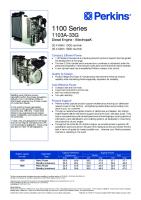
Optional Service Tools Illustration 1
g01143634
Table 2 lists the optional service tools that can be used when the engine is serviced. Table 2
Service welding guide (typical diagram)
Part Number
5. When possible, connect the welder ground clamp directly to the engine component that will be welded. Place the clamp as close as possible to the weld. A close connection will reduce the possibility of welding current damage to the engine bearings, to the electrical components, and to other components. 6. Protect the wiring harnesses from welding debris and/or from the welding spatter. 7. Use standard welding procedures to weld the materials together. i06151874
Electronic Service Tools The electronic service tools are designed to help the service technician perform the following tasks: • Information access • System diagnostics • System calibrations • System configurations • Data link communications
Description
U5MK1092
Spoon Probe Kit (MULTIMETER)
or -
Suitable Digital Pressure Indicator or Engine Pressure Group
-
Suitable Battery Load Tester
-
Suitable Temperature Adapter (MULTIMETER)
2900A038
Bypass Harness As
2900A036
Stub as
Perkins Electronic Service Tool The Perkins Electronic Service Tool can display the following information: • Status of all pressure sensors and temperature sensors • Programmable parameter settings • Active diagnostic codes and logged diagnostic codes • Logged events • Histograms The Electronic Service Tool can also be used to perform the following functions: • Diagnostic tests • Sensor calibrations • Programming of flash files and injector trim codes
This document has been printed from SPI2. NOT FOR RESALE
7
M0075246-01
Introduction
• Parameter programming • Copy configuration function for ECM replacement
Connecting the Electronic Service Tool and the TIPSS Adapter
• Data logging • Graphs (real time) Table 3 lists the service tools that are required in order to use the Electronic Service Tool. Table 3
Service Tools for the Use of the Electronic Service Tool Part Number -(1) -
(1)
27610164
27610401 (1)
Description Single Use Program License Data Subscription for All Engines TIPSS Adapter Kit (Electronic Service Tool to the ECM interface) or Perkins CA3 Kit
Refer to Perkins Engine Company Limited.
Note: For more information on the Electronic Service Tool and the PC requirements, refer to the documentation that accompanies the software for the Electronic Service Tool.
Illustration 2
g01121866
(1) Personal Computer (PC) (2) Adapter Cable (Computer Serial Port) (3) TIPSS adapter (4) Adapter Cable Assembly
Note: Items (2), (3) and (4) are part of the TIPSS adapter kit. Use the following procedure in order to connect the Electronic Service Tool and the TIPSS Adapter. 1. Turn the keyswitch to the OFF position. 2. Connect cable (2) between the “COMPUTER” end of TIPSS adapter (3) and the RS232 serial port of PC (1). Note: The Adapter Cable Assembly (4) is required to connect to the USB port on computers that are not equipped with an RS232 serial port. 3. Connect cable (4) between the “DATA LINK” end of TIPSS adapter (3) and the service tool connector.
This document has been printed from SPI2. NOT FOR RESALE
8 Introduction
M0075246-01
4. Place the keyswitch in the ON position. If the Electronic Service Tool and the TIPSS adapter do not communicate with the Electronic Control Module (ECM), refer to the diagnostic procedure Troubleshooting, “Electronic Service Tool Does Not Communicate”.
4. Place the keyswitch in the ON position. If the Electronic Service Tool and the CA3 adapter do not communicate with the Electronic Control Module (ECM), refer to the diagnostic procedure Troubleshooting, “Electronic Service Tool Does Not Communicate”.
Connecting the Electronic Service Tool and the CA3 Kit
Illustration 3
g01121866
(1) Personal Computer (PC) (2) Adapter Cable (Computer Serial Port) (3) CA3 adapter (4) Adapter Cable Assembly
Note: Items (2), (3) and (4) are part of the CA3 kit. Use the following procedure in order to connect the Electronic Service Tool and the CA3 Adapter. 1. Turn the keyswitch to the OFF position. 2. Connect cable (2) between the “COMPUTER” end of CA3 adapter (3) and a USB port of PC (1). 3. Connect cable (4) between the “DATA LINK” end of CA3 adapter (3) and the service tool connector.
This document has been printed from SPI2. NOT FOR RESALE
M0075246-01
9 Electronic System Overview
Electronic System Overview i06781287
System Overview
The ECM adjusts timing for optimum engine performance and for the fuel economy. Actual timing and desired timing cannot be viewed with the electronic service tool. The ECM determines the location of top center of the number one cylinder from the signals that are provided by the engine speed/ timing sensors. The ECM determines when injection should occur relative to the top center position. The ECM then provides the signal to the injector at the correct time.
Fuel Injection The engine is designed for electronic control of most engine operating functions. The electronic system consists of an Electronic Control Module (ECM), the wiring harness, switches, sensors, and fuel injectors. The engine ECM receives information from the sensors and the switches on the engine. The engine ECM processes the information that is collected to control the engine. By altering the fuel delivery with the fuel injectors, the engine ECM controls the speed and the power that is produced by the engine. The aftertreatment system is controlled by the engine ECM.
The common rail fuel system is controlled by the ECM. The ECM gathers data from several sensors on the engine. The ECM then uses this data to adjust the quantity of fuel being delivered as well as the timing of the injection event. The injection event begins when the ECM sends a signal to the injector solenoid to actuate the valve inside the injector. As the valve opens, the fuel flows from the fuel rail, through the fuel line, and into the injector. As the valve opening pressure is reached, the valve is lifted and the fuel is delivered at high pressure into the combustion chamber.
The following information provides a general description of the control system. Refer to the Systems Operation manual for detailed information about the control system.
The flash file inside the ECM establishes certain limits on the amount of fuel that can be injected. The “FRC Fuel Limit” is a limit that is based on the intake manifold pressure. The “FRC Fuel Limit” is used to control the air/fuel ratio for control of emissions. When the ECM senses a higher intake manifold pressure, the ECM increases the “FRC Fuel Limit” . A higher intake manifold pressure indicates that there is more air in the cylinder. When the ECM increases the “FRC Fuel Limit” , the ECM changes the control signal to the injector. The signal will allow more fuel into the cylinder.
System Operation Engine Governor The ECM governs the engine. The ECM determines the timing, the injection pressure, and the amount of fuel that is delivered to each cylinder. These factors are based on the actual conditions and on the desired conditions at any given time during starting and operation. For variable speed engines, the ECM uses the throttle position sensor to determine the desired engine speed. The ECM compares the desired engine speed to the actual engine speed. The actual engine speed is determined through interpretation of the signals that are received by the ECM from the engine speed/timing sensors. If the desired engine speed is greater than the actual engine speed, the ECM allows more fuel to be injected, increasing engine speed.
Timing Considerations Once the ECM has determined the amount of fuel that is required, the ECM must determine the timing of the fuel injection.
The “Rated Fuel Limit” is a limit that is based on the power rating of the engine and on the engine rpm. The “Rated Fuel Limit” is like the rack stops and the torque spring on a mechanically governed engine. The “Rated Fuel Limit” provides the power curves and the torque curves for a specific engine family and a specific engine rating. All these limits are determined at the factory. These limits cannot be changed.
Other ECM Functions for Performance The ECM may also provide enhanced control of the engine for functions such as controlling the cooling fan. Refer to Troubleshooting, “Configuration Parameters” for supplementary information about the systems that can be monitored and controlled by the ECM.
This document has been printed from SPI2. NOT FOR RESALE
10
M0075246-01
Electronic System Overview
Programmable Parameters Certain parameters that affect engine operation may be changed with the electronic service tool. The parameters are stored in the ECM, and the parameters are protected from unauthorized changes by passwords. These parameters are either system configuration parameters or customer parameters.
Customer passwords may be required to change customer specified parameters. Refer to Troubleshooting, “Configuration Parameters” for additional information on this subject.
Passwords
System configuration parameters are set at the factory. System configuration parameters affect emissions or power ratings. Factory passwords must be obtained and factory passwords must be used to change the system configuration parameters.
System configuration parameters are protected by factory passwords. Factory passwords are calculated on a computer system that is available only to Perkins distributors. Since factory passwords contain alphabetic characters, only the electronic service tool can be used to change system configuration parameters.
Some of the parameters may affect engine operation in an unusual way. An operator might not expect this type of effect. Without adequate training, these parameters may lead to power complaints or performance complaints even though the engine performance is within the specification.
Customer parameters can be protected by customer passwords. The customer passwords are programmed by the customer. Factory passwords can be used to change customer passwords if customer passwords are lost.
Customer parameters can be used to affect the characteristics of the engine. Limits are set by the factory and by the monitoring system.
This document has been printed from SPI2. NOT FOR RESALE
M0075246-01
11 Electronic System Overview
Refer to Troubleshooting, “Customer Passwords” and Troubleshooting, “Factory Passwords” for
additional information on this subject.
i06781289
Component Location Electronic Control Circuit Diagram
Illustration 4
g02476570
Electronic control circuit diagram for a typical 1204E engine
This document has been printed from SPI2. NOT FOR RESALE
12
M0075246-01
Electronic System Overview
Illustration 5
g02476572
Electronic control circuit diagram for a typical 1206E engine Table 4 Components That May Be Only Applicable For Certain Applications Speed Control Input
Coolant Level Sensor
Ambient Air Temperature Sensor
Ether Solenoid
Air Filter Restriction Pressure Sensor
This document has been printed from SPI2. NOT FOR RESALE
M0075246-01
13 Electronic System Overview
Typical 1204E Engine
Illustration 6
g06098746
Sensor locations on the left side of a typical 1204E engine (1) Intake manifold air temperature sensor (2) Intake manifold pressure sensor (3) Water-in-fuel switch (4) Electronic Control Module (ECM)
(5) Barometric pressure sensor (6) Primary speed/timing sensor (7) Oil pressure sensor (8) Fuel temperature sensor
(9) Solenoid for the high-pressure fuel pump (10) Coolant temperature sensor (11) Fuel rail pressure sensor
This document has been printed from SPI2. NOT FOR RESALE
14
M0075246-01
Electronic System Overview
Illustration 7
g06098840
Close up views of sensor locations on the left side of a typical 1204E engine (1) Intake manifold air temperature sensor (2) Intake manifold pressure sensor (3) Water-in-fuel switch (4) Electronic Control Module (ECM)
(5) Barometric pressure sensor (6) Primary speed/timing sensor (7) Oil pressure sensor (8) Fuel temperature sensor
(9) Solenoid for the high-pressure fuel pump (10) Coolant temperature sensor (11) Fuel rail pressure sensor
This document has been printed from SPI2. NOT FOR RESALE
M0075246-01
15 Electronic System Overview
Illustration 8
g06099155
Sensor locations on the right side and top of a typical 1204E engine (12) NOx Reduction System (NRS) temperature sensor (13) NRS valve including a position sensor (14) NRS outlet pressure sensor
(15) NRS inlet pressure sensor (16) Wastegate regulator (17) Secondary speed/timing sensor (not shown)
(18) Exhaust Back Pressure Regulator (EBPR)
This document has been printed from SPI2. NOT FOR RESALE
16
M0075246-01
Electronic System Overview
Illustration 9
g06099179
Sensor locations on the right side and top of a typical 1204E engine (12) NOx Reduction System (NRS) temperature sensor (not shown) (13) NRS valve including a position sensor (14) NRS outlet pressure sensor
(15) NRS inlet pressure sensor (16) Wastegate regulator (17) Secondary speed/timing sensor (not shown)
(18) Exhaust Back Pressure Regulator (EBPR)
This document has been printed from SPI2. NOT FOR RESALE
M0075246-01
17 Electronic System Overview
Typical 1206E Engine
Illustration 10
g06099223
Sensor locations on the left side of a typical 1206E engine (1) Fuel rail pressure sensor (not shown) (2) Intake manifold pressure sensor (3) Intake manifold air temperature sensor (4) Electronic Control Module (ECM)
(5) Barometric pressure sensor (not shown) (6) Primary speed/timing sensor (7) Oil pressure sensor (8) Water-in-fuel switch
(9) Fuel temperature sensor (10) Solenoid for the high-pressure fuel pump (11) Coolant temperature sensor
This document has been printed from SPI2. NOT FOR RESALE
18
M0075246-01
Electronic System Overview
Illustration 11
g06099261
Close up views of sensor locations on the left side of a typical 1206E engine (1) Fuel rail pressure sensor (2) Intake manifold pressure sensor (3) Intake manifold air temperature sensor (4) Electronic Control Module (ECM)
(5) Barometric pressure sensor (6) Primary speed/timing sensor (7) Oil pressure sensor (8) Water-in-fuel switch
(9) Fuel temperature sensor (10) Solenoid for the high-pressure fuel pump (11) Coolant temperature sensor
This document has been printed from SPI2. NOT FOR RESALE
M0075246-01
19 Electronic System Overview
Illustration 12
g06099277
Sensor locations on the right side and top of a typical 1206E engine (12) NOx Reduction System (NRS) outlet pressure sensor (13) NRS inlet pressure sensor
(14) NRS temperature sensor (15) NRS valve including a position sensor (16) Wastegate regulator
(17) Exhaust Back Pressure Regulator (EBPR) (18) Secondary speed/timing sensor
This document has been printed from SPI2. NOT FOR RESALE
20
M0075246-01
Electronic System Overview
Illustration 13
g06099297
Sensor locations on the right side and top of a typical 1206E engine (12) NOx Reduction System (NRS) outlet pressure sensor (13) NRS inlet pressure sensor (14) NRS temperature sensor
(15) NRS valve including a position sensor (16) Wastegate regulator (17) Exhaust Back Pressure Regulator (EBPR)
(18) Secondary speed/timing sensor (not shown)
This document has been printed from SPI2. NOT FOR RESALE
M0075246-01
21 Electronic System Overview
Typical Clean Emissions Module (CEM)
Illustration 14
g06099332
Sensors and components on a typical Clean Emissions Module (CEM) (1) Probe for the DOC inlet temperature sensor
(2) DOC inlet temperature sensor (3) Aftertreatment ID module
i06781290
Engine Monitoring System
(4) Soot antennas
The following actions may be initiated by the ECM. These actions depend on the severity of the condition. • Illumination of a warning lamp or warning alarm
The Electronic Control Module (ECM) provides a comprehensive, programmable engine monitoring system for this engine. The ECM monitors specific engine operating parameters to detect abnormal conditions that may develop. The ECM will generate an event code if a specific engine parameter exceeds an acceptable range that is defined by the engine monitoring system. The ECM will react with an action that depends on the severity of the condition. For information on event codes, refer to Troubleshooting, “Event Codes”.
• Engine derates • Engine shutdown Three possible responses may be available for each parameter. Some of the responses are not available for some of the parameters. Refer to Table 5 .
This document has been printed from SPI2. NOT FOR RESALE
22
M0075246-01
Electronic System Overview
Table 5
Warning Category Indicator
Severity
(1)
Least Severe
(2)
Moderate Severity
(3)
Most Severe
Use the electronic service tool to perform the following activities for the monitoring system:
Note: If a factory password is required, the “Enter Factory Passwords” screen will appear. Refer to Troubleshooting, “Factory Passwords” for information on obtaining factory passwords. The new settings will be effective immediately. Note: Factory passwords are only available to service technicians from an authorized Perkins distributor. Customers of Perkins do not have access to the Factory Password System (FPS).
• Viewing parameters i05977029
• Parameter programming • Set delay times
Diagnostic Capabilities
The default settings for the parameters are programmed at the factory. To accommodate unique applications and sites, some of the parameters may be reprogrammed with the electronic service tool. Use the electronic service tool to modify the monitoring system parameters.
Diagnostic Codes
Note: Some parameters do not require a password to be changed. Other parameters can be changed with customer passwords. Certain parameters are protected by factory passwords. Some parameters cannot be changed. Some applications do not allow any changes to the programmable monitoring system. Parameters that are protected by factory passwords can only be changed by dealer personnel.
Viewing or Changing the Settings of the Monitoring System Use the following procedure to view the parameter settings and/or change the parameter settings: 1. Select the “Service/Monitoring System” screen on the electronic service tool. Note: Ensure that you select the correct ECM for the parameters that are being changed before continuing. 2. Highlight the desired parameter. Then click the “Change” button in the lower left corner of the screen. The “Change Monitor System” screen will appear.
The engines Electronic Control Module (ECM) can monitor the circuitry between the ECM and the engines components. The ECM can also monitor the engines operating conditions. If the ECM detects a problem, a code is generated. There are two categories of codes: • Diagnostic code • Event code Diagnostic Code – A diagnostic code indicates an electrical problem such as a short circuit or an open circuit in the engines wiring or in an electrical component. Event Code – An event code is generated by the detection of an abnormal engine operating condition. For example, an event code will be generated if the oil pressure is too low. In this case, the event code indicates the symptom of a problem. Generally, event codes indicate abnormal operating conditions or mechanical problems rather than electrical problems. Codes can have two different states: • Active • Logged
3. Change the “State” of the parameter.
Active Codes
4. Set the “Trip Point” and the “Delay Time” according to the “Allowed Values” that are displayed in the lower half of the screen.
An active code indicates that a problem is present. Service the active code first. For the appropriate troubleshooting procedure for a particular code, refer to the following troubleshooting procedure:
5. Click the “OK” button. If a password is required, the “Enter Passwords” screen will appear. Enter the correct passwords and then click the “OK” button.
• Troubleshooting, “Diagnostic Trouble Codes” • Troubleshooting, “Event Codes”
This document has been printed from SPI2. NOT FOR RESALE
M0075246-01
23 Electronic System Overview
Logged Codes The codes are logged and stored in the ECM memory. The problem may have been repaired and/ or the problem may no longer exist. If the system is powered, an active diagnostic code may be generated whenever a component is disconnected. If the component is reconnected, the code is no longer active but the code may become logged. Logged codes may not indicate that a repair is needed. The problem may have been temporary. Logged codes may be useful to help troubleshoot intermittent problems. Logged codes can also be used to review the performance of the engine and of the electronic system. Illustration 16
An additional status screen is available for the Enhanced Troubleshooting Indicator ETI. The screen is accessed through the electronic service tool. i06739421
Electrical Connectors
g01877813
Removal Tool 1. Remove the connector from the ECM. Refer to Disassembly and Assembly, “Electronic Control Module - Remove and Install”. 2. Position Tooling (A) around wire (2). Note: Make sure that the tool stays perpendicular to the face of connector (1).
Connectors for the Electronic Control Module (ECM) The Electronic Control Module (ECM) uses connectors that have 70 terminals to interface to the wiring harness.
3. Push the tool into the hole for the terminal. Gently pull the wire to remove the terminal from the rear of connector (1). 4. Remove the Tooling (A) from the wire. Note: If a terminal must be replaced, part number 9X-3402 must be used for 16 and 18 AWG wire. Part number 126-1768 must be used for 14 AWG wire.
Terminal Insertion 1. Push the terminal into the rear of connector (1) until the terminal engages with the locking device. 2. Gently pull on wire (2) to make sure that the terminal is retained by the locking device.
Illustration 15
g01877659
3. Connect the connector to the ECM and then tighten the retaining screw to a torque of 6 N·m (53 lb in).
Layout of the Connector Pins (view from the rear)
Terminal Removal Table 6 Required Tools Tool
Part Number
A
151-6320
Part Description Removal Tool (Red)
Qty 1
This document has been printed from SPI2. NOT FOR RESALE
24
M0075246-01
Electronic System Overview
Injector Connectors
Analog Sensor Connector (passive)
Connectors at the valve cover
Illustration 19
g01241538
Connectors for the Termination Resistor
Illustration 17
g06099709
Sensor Connectors Analog Sensor Connector (active)
Illustration 20
g01355248
Engine Speed/Timing Connector Illustration 18
g01240891
Illustration 21
g01155187
This document has been printed from SPI2. NOT FOR RESALE
M0075246-01
25 Electronic System Overview
Ampseal Connector (typical)
Illustration 22
g02219254
Deutsch Connectors (typical)
Illustration 23
g02220494
This document has been printed from SPI2. NOT FOR RESALE
26
M0075246-01
Configuration Parameters
Configuration Parameters i06781292
Configuration Parameters Use this procedure if the diagnostic code in Table 7 is active. Table 7
Codes That Relate to Configuration Parameters J1939 Code
630-2
PDL Code
268-2
Code Description (code descriptions may vary)
Comments
The engine Electronic Control Module (ECM) detects that one or more of the programmable parameters have not been Programmed Parameter Fault : Erprogrammed. ratic, Intermittent, or Incorrect The ECM may use a default torque map or the ECM may limit the engine to low idle. The code is active only.
Follow the troubleshooting procedure to identify the root cause of the problem.
The electronic service tool can be used to view certain parameters that can affect the operation of the engine. The electronic service tool can also be used to change certain parameters. Some parameters cannot be changed and some applications do not allow any changes to the programmable monitoring system. The parameters are stored in the Electronic Control Module (ECM). Some of the parameters are protected from unauthorized changes by passwords. Parameters that can be changed have a tattletale number. The tattletale number shows if a parameter has been changed. The parameters are divided into two different types: Customer Specified Parameters – Customer passwords may be required to change the values of customer specified parameters. System Configuration Parameters – System configuration parameters affect the emissions of the engine or the power of the engine. Factory passwords may be required to change the values of system configuration parameters.
This document has been printed from SPI2. NOT FOR RESALE
M0075246-01
27 Configuration Parameters
Illustration 24
g03747092
Typical configuration screen 1. Connect to the electronic service tool. 2. Select the Service tab. 3. Select the Configuration tab to view the configuration parameters. If an ECM is replaced, the appropriate parameters must be copied from the old ECM. Copy the parameters with the “Copy Configuration” feature of the electronic service tool. The “Copy Configuration” tab is below the “Configuration” tab. Alternatively, the settings can be recorded on paper and then programmed into the configuration screen for the new module. NOTICE Changing the parameters during engine operation can cause the engine to operate erratically and can cause engine damage. Only change the settings of the parameters when the engine is STOPPED.
This document has been printed from SPI2. NOT FOR RESALE
28
M0075246-01
Configuration Parameters
Check Programmable Parameters 630-2 (268-2)
Illustration 25
g03747100
Typical active diagnostic codes screen If a programmable parameter has not been programmed, the ECM will generate a 630-2 (268-2) diagnostic code. The programmable parameter that is not programmed will be listed under the code. Illustration 24 shows the parameters that are not programmed under the 630-2 (268-2) code. The unprogrammed parameters will be set to default. Certain aspects of the engines performance and engine monitoring may be affected. If “Injector Trim” is displayed below a 630-2 (268-2) diagnostic code on the electronic service tool, refer to Troubleshooting, “Injector Code - Calibrate”.
This document has been printed from SPI2. NOT FOR RESALE
M0075246-01
29 Diagnostic Trouble Codes
Diagnostic Trouble Codes i06781311
Diagnostic Trouble Codes Diagnostic Trouble Codes in J1939 Order Table 8 lists the diagnostic trouble codes that apply to the engines that are covered in this manual. The codes are listed in J1939 order. Use the electronic service tool to determine the codes that are active or logged. Then refer to the appropriate troubleshooting procedure for more information. Table 8 List of Diagnostic Trouble Codes J1939 Code and Description
PDL Code and Description
Troubleshooting Procedure
27-3 EGR #1 Valve Position : Voltage Above Normal
3407-3 EGR Valve Position Sensor : Voltage Above Normal
Troubleshooting, “Valve Position - Test”
27-4 3407-4 EGR #1 Valve Position : Voltage Be- EGR Valve Position Sensor : Voltage Below Normal low Normal
Troubleshooting, “Valve Position - Test”
29-2 Accelerator Pedal Position #2 : Erratic, Intermittent, or Incorrect
774-2 Secondary Throttle Position Sensor : Erratic, Intermittent, or Incorrect (Engines with a throttle switch)
Troubleshooting, “Switch Circuits - Test”
29-2 Accelerator Pedal Position #2 : Erratic, Intermittent, or Incorrect
774-2 Secondary Throttle Position Sensor : Erratic, Intermittent, or Incorrect (Engines with an analog throttle)
Troubleshooting, “Speed Control (Analog) - Test”
29-3 Accelerator Pedal Position #2 : Voltage Above Normal
774-3 Secondary Throttle Position Sensor : Voltage Above Normal
Troubleshooting, “Speed Control (Analog) - Test / Speed Control (PWM) - Test”
29-4 Accelerator Pedal Position #2 : Voltage Below Normal
774-4 Secondary Throttle Position Sensor : Voltage Below Normal
Troubleshooting, “Speed Control (Analog) - Test / Speed Control (PWM) - Test”
29-8 774-8 Accelerator Pedal Position #2 : Ab- Secondary Throttle Position Sensor : Abnormal Frequency, Pulse Width, or normal Frequency, Pulse Width, or Period Period 91-2 Accelerator Pedal Position #1 : Erratic, Intermittent, or Incorrect
91-2 Throttle Position Sensor : Erratic, Intermittent, or Incorrect (Engines with a throttle switch)
Troubleshooting, “Speed Control (PWM) - Test”
Troubleshooting, “Switch Circuits - Test”
(continued)
This document has been printed from SPI2. NOT FOR RESALE
30
M0075246-01
Diagnostic Trouble Codes
(Table 8, contd) 91-2 Accelerator Pedal Position #1 : Erratic, Intermittent, or Incorrect
91-2 Throttle Position Sensor : Erratic, Intermittent, or Incorrect (Engines with an analog throttle)
Troubleshooting, “Speed Control (Analog) - Test”
91-3 91-3 Troubleshooting, “Speed Control (Analog) - Test / Speed ConAccelerator Pedal Position #1 : Volt- Throttle Position Sensor : Voltage Above trol (PWM) - Test” age Above Normal Normal 91-4 91-4 Troubleshooting, “Speed Control (Analog) - Test / Speed ConAccelerator Pedal Position #1 : Volt- Throttle Position Sensor : Voltage Below trol (PWM) - Test” age Below Normal Normal 91-8 Accelerator Pedal Position #1 : Abnormal Frequency, Pulse Width, or Period
91-8 Throttle Position Sensor : Abnormal Frequency, Pulse Width, or Period
Troubleshooting, “Speed Control (PWM) - Test”
97-3 Water In Fuel Indicator : Voltage Above Normal
3547-3 Water In Fuel Indicator : Voltage Above Normal
Troubleshooting, “Water in Fuel - Test”
100-3 Engine Oil Pressure : Voltage Above Normal
100-3 Engine Oil Pressure Sensor : Voltage Above Normal
Troubleshooting, “Sensor Signal (Analog, Active) - Test”
100-4 Engine Oil Pressure : Voltage Below Normal
100-4 Engine Oil Pressure Sensor : Voltage Below Normal
Troubleshooting, “Sensor Signal (Analog, Active) - Test”
100-21 Engine Oil Pressure : Data Drifted Low
100-21 Engine Oil Pressure Sensor : Voltage Below Normal
Troubleshooting, “Sensor Supply - Test”
105-3 172-3 Engine Intake Manifold #1 Tempera- Intake Manifold Air Temperature Sensor ture : Voltage Above Normal : Voltage Above Normal
Troubleshooting, “Sensor Signal (Analog, Passive) - Test”
105-4 172-4 Engine Intake Manifold #1 Tempera- Intake Manifold Air Temperature Sensor ture : Voltage Below Normal : Voltage Below Normal
Troubleshooting, “Sensor Signal (Analog, Passive) - Test”
108-3 Barometric Pressure : Voltage Above Normal
3528-3 Barometric Pressure Sensor : Voltage Above Normal
Troubleshooting, “Sensor Signal (Analog, Active) - Test”
108-4 Barometric Pressure : Voltage Below Normal
3528-4 Barometric Pressure Sensor : Voltage Below Normal
Troubleshooting, “Sensor Signal (Analog, Active) - Test”
108-21 Barometric Pressure : Data Drifted Low
3528-21 Barometric Pressure Sensor : Data Drifted Low
Troubleshooting, “Sensor Supply - Test”
110-3 Engine Coolant Temperature : Voltage Above Normal
110-3 Engine Coolant Temperature Sensor : Voltage Above Normal
Troubleshooting, “Sensor Signal (Analog, Passive) - Test”
110-4 Engine Coolant Temperature : Voltage Below Normal
110-4 Engine Coolant Temperature Sensor : Voltage Below Normal
Troubleshooting, “Sensor Signal (Analog, Passive) - Test”
157-3 Engine Injector Metering Rail #1 Pressure : Voltage Above Normal
1797-3 Fuel Rail Pressure Sensor : Voltage Above Normal
Troubleshooting, “Sensor Signal (Analog, Active) - Test”
(continued)
This document has been printed from SPI2. NOT FOR RESALE
M0075246-01
31 Diagnostic Trouble Codes
(Table 8, contd) 157-4 Engine Injector Metering Rail #1 Pressure : Voltage Below Normal
1797-4 Fuel Rail Pressure Sensor : Voltage Below Normal
Troubleshooting, “Sensor Signal (Analog, Active) - Test”
168-2 Battery Potential / Power Input #1 : Erratic, Intermittent or incorrect
168-2 Electrical System Voltage : Erratic, Intermittent or incorrect
Troubleshooting, “Electrical Power Supply - Test”
168-3 Battery Potential / Power Input #1 : Voltage Above Normal
168-3 Electrical System Voltage : Voltage Above Normal
Troubleshooting, “Electrical Power Supply - Test”
168-4 Battery Potential / Power Input #1 : Voltage Below Normal
168-4 Electrical System Voltage : Voltage Below Normal
Troubleshooting, “Electrical Power Supply - Test”
172-3 Engine Air Inlet Temperature : Voltage Above Normal
2526-3 Air Inlet Temperature Sensor : Voltage Above Normal
Troubleshooting, “Sensor Signal (Analog, Passive) - Test”
172-4 Engine Air Inlet Temperature : Voltage Below Normal
2526-4 Air Inlet Temperature Sensor : Voltage Below Normal
Troubleshooting, “Sensor Signal (Analog, Passive) - Test”
174-3 Engine Fuel Temperature 1 : Voltage Above Normal
174-3 Fuel Temperature Sensor : Voltage Above Normal
Troubleshooting, “Sensor Signal (Analog, Passive) - Test”
174-4 Engine Fuel Temperature 1 : Voltage Below Normal
174-4 Fuel Temperature Sensor : Voltage Below Normal
Troubleshooting, “Sensor Signal (Analog, Passive) - Test”
190-8 Engine Speed : Abnormal Frequency, Pulse Width, or Period
190-8 Engine Speed Sensor : Abnormal Frequency, Pulse Width, or Period
Troubleshooting, “Speed/Timing - Test”
412-3 Engine Exhaust Gas Recirculation Temperature : Voltage Above Normal
3386-3 EGR Temperature Sensor : Voltage Above Normal
Troubleshooting, “Sensor Signal (Analog, Passive) - Test”
412-4 3386-4 Engine Exhaust Gas Recirculation EGR Temperature Sensor : Voltage BeTemperature : Voltage Below Normal low Normal
Troubleshooting, “Sensor Signal (Analog, Passive) - Test”
558-2 1634-2 Accelerator Pedal #1 Low Idle Switch Idle Validation Switch #1 : Erratic, Inter: Erratic, Intermittent, or Incorrect mittent, or Incorrect
Troubleshooting, “Idle Validation - Test”
626-5 Engine Start Enable Device 1 : Current Below Normal
2417-5 Ether Injection Control Solenoid : Current Below Normal
Troubleshooting, “Ether Starting Aid - Test”
626-6 Engine Start Enable Device 1 : Current Above Normal
2417-6 Ether Injection Control Solenoid : Current Above Normal
Troubleshooting, “Ether Starting Aid - Test”
630-2 Calibration Memory : Erratic, Intermittent, or Incorrect
268-2 Programmed Parameter Fault : Erratic, Intermittent, or Incorrect
Troubleshooting, “Configuration Parameters”
631-2 253-2 Calibration Module : Erratic, Intermit- Personality Module : Erratic, Intermittent, tent, or Incorrect or Incorrect 637-11 Engine Timing Sensor : Other Failure Mode
261-11 Engine Timing Offset fault
Troubleshooting, “ECM Software - Install”
Troubleshooting, “Speed/Timing - Test”
(continued)
This document has been printed from SPI2. NOT FOR RESALE
32
M0075246-01
Diagnostic Trouble Codes
(Table 8, contd) 639-9 J1939 Network #1 : Abnormal Update Rate
247-9 SAE J1939 Data Link : Abnormal Update Rate
Troubleshooting, “CAN Data Link - Test”
649-3 3512-3 Engine Exhaust Back Pressure RegEngine Exhaust Back Pressure Regulaulator Control Command : Voltage tor : Voltage Above Normal Above Normal
Troubleshooting, “Motorized Valve - Test”
649-5 3512-5 Engine Exhaust Back Pressure RegEngine Exhaust Back Pressure Regulaulator Control Command : Current tor : Current Below Normal Below Normal
Troubleshooting, “Motorized Valve - Test”
649-6 3512-6 Engine Exhaust Back Pressure RegEngine Exhaust Back Pressure Regulaulator Control Command : -Current tor : Current Above Normal Above Normal
Troubleshooting, “Motorized Valve - Test”
651-2 Engine Injector Cylinder #01 : Erratic, Intermittent, or Incorrect
1-2 Cylinder #1 Injector : Erratic, Intermittent, or Incorrect
Troubleshooting, “Injector Data Incorrect - Test”
651-5 Engine Injector Cylinder #01 : Current Below Normal
1-5 Cylinder #1 Injector : Current Below Normal
Troubleshooting, “Injector Solenoid - Test”
651-6 Engine Injector Cylinder #01 : Current Above Normal
1-6 Cylinder #1 Injector : Current Above Normal
Troubleshooting, “Injector Solenoid - Test”
652-2 Engine Injector Cylinder #02 : Erratic, Intermittent, or Incorrect
2-2 Cylinder #2 Injector : Erratic, Intermittent, or Incorrect
Troubleshooting, “Injector Data Incorrect - Test”
652-5 Engine Injector Cylinder #02 : Current Below Normal
2-5 Cylinder #2 Injector : Current Below Normal
Troubleshooting, “Injector Solenoid - Test”
652-6 Engine Injector Cylinder #02 : Current Above Normal
2-6 Cylinder #2 Injector : Current Above Normal
Troubleshooting, “Injector Solenoid - Test”
653-2 Engine Injector Cylinder #03 : Erratic, Intermittent, or Incorrect
3-2 Cylinder #3 Injector : Erratic, Intermittent, or Incorrect
Troubleshooting, “Injector Data Incorrect - Test”
653-5 Engine Injector Cylinder #03 : Current Below Normal
3-5 Cylinder #3 Injector : Current Below Normal
Troubleshooting, “Injector Solenoid - Test”
653-6 Engine Injector Cylinder #03 : Current Above Normal
3-6 Cylinder #3 Injector : Current Above Normal
Troubleshooting, “Injector Solenoid - Test”
654-2 Engine Injector Cylinder #04 : Erratic, Intermittent, or Incorrect
4-2 Cylinder #4 Injector : Erratic, Intermittent, or Incorrect
Troubleshooting, “Injector Data Incorrect - Test”
654-5 Engine Injector Cylinder #04 : Current Below Normal
4-5 Cylinder #4 Injector : Current Below Normal
Troubleshooting, “Injector Solenoid - Test”
654-6 Engine Injector Cylinder #04 : Current Above Normal
4-6 Cylinder #4 Injector : Current Above Normal
Troubleshooting, “Injector Solenoid - Test”
(continued)
This document has been printed from SPI2. NOT FOR RESALE
M0075246-01
33 Diagnostic Trouble Codes
(Table 8, contd) 655-2 Engine Injector Cylinder #05 : Erratic, Intermittent, or Incorrect (C6.6 Engine Only)
5-2 Cylinder #5 Injector : Erratic, Intermittent, or Incorrect (C6.6 Engine Only)
Troubleshooting, “Injector Data Incorrect - Test”
655-5 Engine Injector Cylinder #05 : Current Below Normal (C6.6 Engine Only)
5-5 Cylinder #5 Injector : Current Below Normal (C6.6 Engine Only)
Troubleshooting, “Injector Solenoid - Test”
655-6 Engine Injector Cylinder #05 : Current Above Normal (C6.6 Engine Only)
5-6 Cylinder #5 Injector : Current Above Normal (C6.6 Engine Only)
Troubleshooting, “Injector Solenoid - Test”
656-2 Engine Injector Cylinder #06 : Erratic, Intermittent, or Incorrect (C6.6 Engine Only)
6-2 Cylinder #6 Injector : Erratic, Intermittent, or Incorrect (C6.6 Engine Only)
Troubleshooting, “Injector Data Incorrect - Test”
656-5 Engine Injector Cylinder #06 : Current Below Normal (C6.6 Engine Only)
6-5 Cylinder #6 Injector : Current Below Normal (C6.6 Engine Only)
Troubleshooting, “Injector Solenoid - Test”
656-6 Engine Injector Cylinder #06 : Current Above Normal (C6.6 Engine Only)
6-6 Cylinder #6 Injector : Current Above Normal (C6.6 Engine Only)
Troubleshooting, “Injector Solenoid - Test”
676-6 Engine Glow Plug Relay : Current Above Normal
2246-6 Glow Plug Start Aid Relay : Current Above Normal
Troubleshooting, “Glow Plug Starting Aid - Test”
678-3 ECU 8 Volts DC Supply : Voltage Above Normal
41-3 8 Volt DC Supply : Voltage Above Normal
Troubleshooting, “Sensor Supply - Test”
678-4 ECU 8 Volts DC Supply : Voltage Below Normal
41-4 8 Volt DC Supply : Voltage Below Normal
Troubleshooting, “Sensor Supply - Test”
723-8 Engine Speed Sensor #2 : Abnormal Frequency, Pulse Width, or Period
342-8 Secondary Engine Speed Sensor : Abnormal Frequency, Pulse Width, or Period
Troubleshooting, “Speed/Timing - Test”
1075-5 Engine Electric Lift Pump for Engine Fuel Supply : Current Below Normal
3666-5 Engine Fuel Supply Lift Pump Relay : Current Below Normal
Troubleshooting, “Fuel Transfer Pump - Test”
1075-6 Engine Electric Lift Pump for Engine Fuel Supply : Current Above Normal
3666-6 Engine Fuel Supply Lift Pump Relay : Current Above Normal
Troubleshooting, “Fuel Transfer Pump - Test”
1076-5 Engine Fuel Injection Pump Fuel Control Valve : Current Below Normal
18-5 Fuel Control Valve : Current Below Normal
Troubleshooting, “Solenoid Valve - Test”
1076-6 Engine Fuel Injection Pump Fuel Control Valve : Current Above Normal
18-6 Fuel Control Valve : Current Above Normal
Troubleshooting, “Solenoid Valve - Test”
(continued)
This document has been printed from SPI2. NOT FOR RESALE
34
M0075246-01
Diagnostic Trouble Codes
(Table 8, contd) 1188-3 Engine Turbocharger #1 Wastegate Drive : Voltage Above Normal
526-3 Turbo Wastegate Drive : Voltage Above Normal
Troubleshooting, “Solenoid Valve - Test”
1188-5 Engine Turbocharger #1 Wastegate Drive : Current Below Normal
526-5 Turbo Wastegate Drive : Current Below Normal
Troubleshooting, “Solenoid Valve - Test”
1188-6 Engine Turbocharger #1 Wastegate Drive : Current Above Normal
526-6 Turbo Wastegate Drive : Current Above Normal
Troubleshooting, “Solenoid Valve - Test”
2791-3 Engine Exhaust Gas Recirculation (EGR) Valve Control : Voltage Above Normal
3405-3 EGR Valve Control : Voltage Above Normal
Troubleshooting, “Motorized Valve - Test”
2791-5 Engine Exhaust Gas Recirculation (EGR) Valve Control : Current Below Normal
3405-5 EGR Valve Control : Current Below Normal
Troubleshooting, “Motorized Valve - Test”
2791-6 Engine Exhaust Gas Recirculation (EGR) Valve Control : Current Above Normal
3405-6 EGR Valve Control : Current Above Normal
Troubleshooting, “Motorized Valve - Test”
2882-2 Engine Alternate Rating Select : Erratic, Intermittent, or Incorrect
1743-2 Engine Operation Mode Selector Switch : Erratic, Intermittent, or Incorrect
Troubleshooting, “Mode Selection - Test”
2970-2 Accelerator Pedal #2 Low Idle Switch : Erratic, Intermittent, or Incorrect
774-0 Secondary Throttle Position Sensor : High
Troubleshooting, “Idle Validation - Test”
2970-2 1635-2 Accelerator Pedal #2 Low Idle Switch Idle Validation Switch #2 : Erratic, Inter: Erratic, Intermittent, or Incorrect mittent, or Incorrect
Troubleshooting, “Idle Validation - Test”
3242-3 Aftertreatment #1 DPF Intake Gas Temperature : Voltage Above Normal
2452-3 DPF #1 Intake Temperature Sensor : Voltage Above Normal
Troubleshooting, “Sensor Signal (Analog, Passive) - Test”
3242-4 Aftertreatment #1 DPF Intake Gas Temperature : Voltage Below Normal
2452-4 DPF #1 Intake Temperature Sensor : Voltage Below Normal
Troubleshooting, “Sensor Signal (Analog, Passive) - Test”
3358-3 Engine Exhaust Gas Recirculation Inlet Pressure : Voltage Above Normal
3385-3 EGR Intake Pressure Sensor : Voltage Above Normal
Troubleshooting, “Sensor Signal (Analog, Active) - Test”
3358-4 Engine Exhaust Gas Recirculation Inlet Pressure : Voltage Below Normal
3385-4 EGR Intake Pressure Sensor : Voltage Below Normal
Troubleshooting, “Sensor Signal (Analog, Active) - Test”
3358-13 Engine Exhaust Gas Recirculation Inlet Pressure : Out of Calibration
3385-13 EGR Intake Pressure Sensor : Out of Calibration
Troubleshooting, “Sensor Calibration Required - Test”
3358-21 Engine Exhaust Gas Recirculation Inlet Pressure : Data Drifted Low
3385-21 EGR Intake Pressure Sensor : Data Drifted Low
Troubleshooting, “Sensor Supply - Test”
3509-3 Sensor Supply Voltage 1 : Voltage Above Normal
262-3 5 Volt Sensor DC Power Supply : Voltage Above Normal
Troubleshooting, “Sensor Supply - Test”
(continued)
This document has been printed from SPI2. NOT FOR RESALE
M0075246-01
35 Diagnostic Trouble Codes
(Table 8, contd) 3509-4 Sensor Supply Voltage 1 : Voltage Below Normal
262-4 5 Volt Sensor DC Power Supply : Voltage Below Normal
Troubleshooting, “Sensor Supply - Test”
3510-3 Sensor Supply Voltage 2 : Voltage Above Normal
2131-3 5 Volt Sensor DC Power Supply #2 : Voltage Above Normal
Troubleshooting, “Sensor Supply - Test”
3510-4 Sensor Supply Voltage 2 : Voltage Below Normal
2131-4 5 Volt Sensor DC Power Supply #2 : Voltage Below Normal
Troubleshooting, “Sensor Supply - Test”
3563-3 Engine Intake Manifold #1 Absolute Pressure : Voltage Above Normal
1785-3 Intake Manifold Pressure Sensor : Voltage Above Normal
Troubleshooting, “Sensor Signal (Analog, Active) - Test”
3563-4 Engine Intake Manifold #1 Absolute Pressure : Voltage Below Normal
1785-4 Intake Manifold Pressure Sensor : Voltage Below Normal
Troubleshooting, “Sensor Signal (Analog, Active) - Test”
3563-13 1785-13 Engine Intake Manifold #1 Absolute Intake Manifold Pressure Sensor : Out of Pressure : Out of Calibration Calibration
Troubleshooting, “Sensor Calibration Required - Test”
3563-21 Engine Intake Manifold #1 Absolute Pressure : Data Drifted Low
1785-21 Intake Manifold Pressure Sensor : Data Drifted Low
Troubleshooting, “Sensor Supply - Test”
4783-3 DPF #1 Mean Soot Signal : Voltage Above Normal
3397-3 DPF #1 Soot Loading Sensor : Voltage Above Normal
Troubleshooting, “Soot Sensor - Test”
4783-4 DPF #1 Mean Soot Signal : Voltage Below Normal
3397-4 DPF #1 Soot Loading Sensor : Voltage Below Normal
Troubleshooting, “Soot Sensor - Test”
4783-9 DPF #1 Mean Soot Signal : Abnormal Update Rate
3397-9 DPF #1 Soot Loading Sensor : Abnormal Update Rate
Troubleshooting, “Soot Sensor - Test”
4783-12 DPF #1 Mean Soot Signal : Failure
3397-12 DPF #1 Soot Loading Sensor : Failure
Troubleshooting, “Soot Sensor - Test”
4783-13 DPF #1 Mean Soot Signal : Calibration Required
3397-13 DPF #1 Soot Loading Sensor : Calibration Required
Troubleshooting, “Soot Sensor - Test”
4783-21 DPF #1 Mean Soot Signal : Data Drifted Low
3397-21 DPF #1 Soot Loading Sensor : Data Drifted Low
Troubleshooting, “Soot Sensor - Test”
5019-3 Engine Exhaust Gas Recirculation Outlet Pressure : Voltage Above Normal
3511-3 Engine Exhaust Gas Recirculation Outlet Pressure Sensor : Voltage Above Normal
Troubleshooting, “Sensor Signal (Analog, Active) - Test”
5019-4 Engine Exhaust Gas Recirculation Outlet Pressure : Voltage Below Normal
3511-4 Engine Exhaust Gas Recirculation Outlet Pressure Sensor : Voltage Below Normal
Troubleshooting, “Sensor Signal (Analog, Active) - Test”
5019-13 Engine Exhaust Gas Recirculation Outlet Pressure : Calibration Required
3511-13 Engine Exhaust Gas Recirculation Outlet Pressure Sensor : Calibration Required
Troubleshooting, “Sensor Calibration Required - Test”
(continued)
This document has been printed from SPI2. NOT FOR RESALE
36
M0075246-01
Diagnostic Trouble Codes
(Table 8, contd) 5019-21 Engine Exhaust Gas Recirculation Outlet Pressure : Data Drifted Low
3511-21 Engine Exhaust Gas Recirculation Outlet Pressure Sensor : Data Drifted Low
Troubleshooting, “Sensor Supply - Test”
5576-2 Aftertreatment #1 Identification : Erratic, Intermittent, or Incorrect
3468-2 Aftertreatment #1 Identification Number Module : Erratic, Intermittent, or Incorrect
Troubleshooting, “Aftertreatment Identification Module - Test”
5576-8 Aftertreatment #1 Identification : Abnormal Frequency, Pulse Width, or Period
3468-8 Aftertreatment #1 Identification Number Module : Abnormal Frequency, Pulse Width, or Period
Troubleshooting, “Aftertreatment Identification Module - Test”
5576-14 Aftertreatment #1 Identification : Special Instruction
3468-14 Aftertreatment #1 Identification Number Module : Special Instruction
Troubleshooting, “Data Link Configuration Status - Test”
5625-3 3513-3 Engine Exhaust Back Pressure Reg- Engine Exhaust Back Pressure Regulaulator Position : Voltage Above tor Valve Position Sensor : Voltage Normal Above Normal
Troubleshooting, “Valve Position - Test”
5625-4 3513-4 Engine Exhaust Back Pressure Reg- Engine Exhaust Back Pressure Regulaulator Position : Voltage Below tor Valve Position Sensor : Voltage BeNormal low Normal
Troubleshooting, “Valve Position - Test”
Diagnostic Trouble Codes in Perkins Data Link (PDL) Code Order Table 9 lists the diagnostic trouble codes that apply to the engines that are covered in this manual. The codes are listed in PDL code order. Use the electronic service tool to determine the codes that are active or logged. Then refer to the appropriate troubleshooting procedure for more information. Table 9 List of Diagnostic Trouble Codes PDL Code and Description
J1939 Code and Description
1-2 651-2 Cylinder #1 Injector : Erratic, Intermit- Engine Injector Cylinder #01 : Erratic, tent, or Incorrect Intermittent, or Incorrect
Troubleshooting Procedure Troubleshooting, “Injector Data Incorrect - Test”
1-5 Cylinder #1 Injector : Current Below Normal
651-5 Engine Injector Cylinder #01 : Current Below Normal
Troubleshooting, “Injector Solenoid - Test”
1-6 Cylinder #1 Injector : Current Above Normal
651-6 Engine Injector Cylinder #01 : Current Above Normal
Troubleshooting, “Injector Solenoid - Test”
2-2 652-2 Cylinder #2 Injector : Erratic, Intermit- Engine Injector Cylinder #02 : Erratic, tent, or Incorrect Intermittent, or Incorrect 2-5 Cylinder #2 Injector : Current Below Normal
652-5 Engine Injector Cylinder #02 : Current Below Normal
Troubleshooting, “Injector Data Incorrect - Test”
Troubleshooting, “Injector Solenoid - Test”
(continued)
This document has been printed from SPI2. NOT FOR RESALE
M0075246-01
37 Diagnostic Trouble Codes
(Table 9, contd) 2-6 Cylinder #2 Injector : Current Above Normal
652-6 Engine Injector Cylinder #02 : Current Above Normal
3-2 653-2 Cylinder #3 Injector : Erratic, Intermit- Engine Injector Cylinder #03 : Erratic, tent, or Incorrect Intermittent, or Incorrect
Troubleshooting, “Injector Solenoid - Test”
Troubleshooting, “Injector Data Incorrect - Test”
3-5 Cylinder #3 Injector : Current Below Normal
653-5 Engine Injector Cylinder #03 : Current Below Normal
Troubleshooting, “Injector Solenoid - Test”
3-6 Cylinder #3 Injector : Current Above Normal
653-6 Engine Injector Cylinder #03 : Current Above Normal
Troubleshooting, “Injector Solenoid - Test”
4-2 654-2 Cylinder #4 Injector : Erratic, Intermit- Engine Injector Cylinder #04 : Erratic, tent, or Incorrect Intermittent, or Incorrect
Troubleshooting, “Injector Data Incorrect - Test”
4-5 Cylinder #4 Injector : Current Below Normal
654-5 Engine Injector Cylinder #04 : Current Below Normal
Troubleshooting, “Injector Solenoid - Test”
4-6 Cylinder #4 Injector : Current Above Normal
654-6 Engine Injector Cylinder #04 : Current Above Normal
Troubleshooting, “Injector Solenoid - Test”
655-2 5-2 Engine Injector Cylinder #05 : Erratic, Cylinder #5 Injector : Erratic, IntermitIntermittent, or Incorrect (C6.6 Engine tent, or Incorrect (C6.6 Engine Only) Only)
Troubleshooting, “Injector Data Incorrect - Test”
5-5 Cylinder #5 Injector : Current Below Normal (C6.6 Engine Only)
655-5 Engine Injector Cylinder #05 : Current Below Normal (C6.6 Engine Only)
Troubleshooting, “Injector Solenoid - Test”
5-6 Cylinder #5 Injector : Current Above Normal (C6.6 Engine Only)
655-6 Engine Injector Cylinder #05 : Current Above Normal (C6.6 Engine Only)
Troubleshooting, “Injector Solenoid - Test”
656-2 6-2 Engine Injector Cylinder #06 : Erratic, Cylinder #6 Injector : Erratic, IntermitIntermittent, or Incorrect (C6.6 Engine tent, or Incorrect (C6.6 Engine Only) Only)
Troubleshooting, “Injector Data Incorrect - Test”
6-5 Cylinder #6 Injector : Current Below Normal (C6.6 Engine Only)
656-5 Engine Injector Cylinder #06 : Current Below Normal (C6.6 Engine Only)
Troubleshooting, “Injector Solenoid - Test”
6-6 Cylinder #6 Injector : Current Above Normal (C6.6 Engine Only)
656-6 Engine Injector Cylinder #06 : Current Above Normal (C6.6 Engine Only)
Troubleshooting, “Injector Solenoid - Test”
18-5 Fuel Control Valve : Current Below Normal
1076-5 Engine Fuel Injection Pump Fuel Control Valve : Current Below Normal
Troubleshooting, “Solenoid Valve - Test”
18-6 Fuel Control Valve : Current Above Normal
1076-6 Engine Fuel Injection Pump Fuel Control Valve : Current Above Normal
Troubleshooting, “Solenoid Valve - Test”
41-3 8 Volt DC Supply : Voltage Above Normal
678-3 ECU 8 Volts DC Supply : Voltage Above Normal
Troubleshooting, “Sensor Supply - Test”
(continued)
This document has been printed from SPI2. NOT FOR RESALE
38
M0075246-01
Diagnostic Trouble Codes
(Table 9, contd) 41-4 8 Volt DC Supply : Voltage Below Normal
678-4 ECU 8 Volts DC Supply : Voltage Below Normal
Troubleshooting, “Sensor Supply - Test”
91-2 Throttle Position Sensor : Erratic, Intermittent, or Incorrect
91-2 Accelerator Pedal Position #1 : Erratic, Intermittent, or Incorrect
Troubleshooting, “Switch Circuits - Test”
91-2 Throttle Position Sensor : Erratic, Intermittent, or Incorrect
91-2 Accelerator Pedal Position #1 : Erratic, Intermittent, or Incorrect
Troubleshooting, “Speed Control (Analog) - Test”
91-3 Throttle Position Sensor : Voltage Above Normal
91-3 Troubleshooting, “Speed Control (Analog) - Test / Speed Control Accelerator Pedal Position #1 : Volt(PWM) - Test” age Above Normal
91-4 Throttle Position Sensor : Voltage Below Normal
91-4 Troubleshooting, “Speed Control (Analog) - Test / Speed Control Accelerator Pedal Position #1 : Volt- Test (PWM)” age Below Normal
91-8 Throttle Position Sensor : Abnormal Frequency, Pulse Width, or Period
91-8 Accelerator Pedal Position #1 : Abnormal Frequency, Pulse Width, or Period
Troubleshooting, “Speed Control (PWM) - Test”
100-3 Engine Oil Pressure Sensor : Voltage Above Normal
100-3 Engine Oil Pressure : Voltage Above Normal
Troubleshooting, “Sensor Signal (Analog, Active) - Test”
100-4 Engine Oil Pressure Sensor : Voltage Below Normal
100-4 Engine Oil Pressure : Voltage Below Normal
Troubleshooting, “Sensor Signal (Analog, Active) - Test”
100-21 Engine Oil Pressure Sensor : Data Drifted Low
100-21 Engine Oil Pressure : Data Drifted Low
Troubleshooting, “Sensor Supply - Test”
110-3 110-3 Engine Coolant Temperature Sensor : Engine Coolant Temperature : Voltage Voltage Above Normal Above Normal
Troubleshooting, “Sensor Signal (Analog, Passive) - Test”
110-4 110-4 Engine Coolant Temperature : Voltage Engine Coolant Temperature Sensor : Voltage Below Normal Below Normal
Troubleshooting, “Sensor Signal (Analog, Passive) - Test”
168-2 Electrical System Voltage : Erratic, Intermittent or Incorrect
168-2 Battery Potential / Power Input #1 : Erratic, Intermittent or Incorrect
Troubleshooting, “Electrical Power Supply - Test”
168-3 Electrical System Voltage : Voltage Above Normal
168-3 Battery Potential / Power Input #1 : Voltage Above Normal
Troubleshooting, “Electrical Power Supply - Test”
168-4 Electrical System Voltage : Voltage Below Normal
168-4 Battery Potential / Power Input #1 : Voltage Below Normal
Troubleshooting, “Electrical Power Supply - Test”
172-3 Intake Manifold Air Temperature Sensor : Voltage Above Normal
105-3 Engine Intake Manifold #1 Temperature : Voltage Above Normal
Troubleshooting, “Sensor Signal (Analog, Passive) - Test”
172-4 Intake Manifold Air Temperature Sensor : Voltage Below Normal
105-4 Engine Intake Manifold #1 Temperature : Voltage Below Normal
Troubleshooting, “Sensor Signal (Analog, Passive) - Test”
174-3 Fuel Temperature Sensor : Voltage Above Normal
174-3 Engine Fuel Temperature 1 : Voltage Above Normal
Troubleshooting, “Sensor Signal (Analog, Passive) - Test”
(continued)
This document has been printed from SPI2. NOT FOR RESALE
M0075246-01
39 Diagnostic Trouble Codes
(Table 9, contd) 174-4 Engine Fuel Temperature 1 : Voltage Below Normal
174-4 Fuel Temperature Sensor : Voltage Below Normal
Troubleshooting, “Sensor Signal (Analog, Passive) - Test”
190-8 190-8 Engine Speed Sensor : Abnormal Fre- Engine Speed : Abnormal Frequency, quency, Pulse Width, or Period Pulse Width, or Period
Troubleshooting, “Speed/Timing - Test”
246-9 Proprietary CAN Data Link : Abnormal Update Rate
-
Troubleshooting, “CAN Data Link - Test”
246-14 Proprietary CAN Data Link : Special Instruction
-
Troubleshooting, “Data Link Configuration Status - Test”
639-9 247-9 SAE J1939 Data Link : Abnormal Up- J1939 Network #1 : Abnormal Update date Rate Rate
Troubleshooting, “Data Link - Test”
253-2 Personality Module : Erratic, Intermittent or Incorrect
631-2 Calibration Module : Erratic, Intermittent or Incorrect
Troubleshooting, “ECM Software - Install”
261-11 Engine Timing Offset fault
637-11 Engine Timing Sensor : Other Failure Mode
Troubleshooting, “Speed/Timing - Test”
262-3 5 Volt Sensor DC Power Supply : Voltage Above Normal
3509-3 Sensor Supply Voltage 1 : Voltage Above Normal
Troubleshooting, “Sensor Supply - Test”
262-4 3509-4 5 Volt Sensor DC Power Supply : Volt- Sensor Supply Voltage 1 : Voltage Beage Below Normal low Normal
Troubleshooting, “Sensor Supply - Test”
268-2 Programmed Parameter Fault : Erratic, Intermittent, or Incorrect
630-2 Calibration Memory : Erratic, Intermittent, or Incorrect
Troubleshooting, “Configuration Parameters”
342-8 Secondary Engine Speed Sensor : Abnormal Frequency, Pulse Width, or Period
723-8 Engine Speed Sensor #2 : Abnormal Frequency, Pulse Width, or Period
Troubleshooting, “Speed/Timing - Test”
526-3 Turbo Wastegate Drive : Voltage Above Normal
1188-3 Engine Turbocharger #1 Wastegate Drive : Voltage Above Normal
Troubleshooting, “Solenoid Valve - Test”
526-5 Turbo Wastegate Drive : Current Below Normal
1188-5 Engine Turbocharger #1 Wastegate Drive : Current Below Normal
Troubleshooting, “Solenoid Valve - Test”
526-6 Turbo Wastegate Drive : Current Above Normal
1188-6 Engine Turbocharger #1 Wastegate Drive : Current Above Normal
Troubleshooting, “Solenoid Valve - Test”
544-8 Engine Cooling Fan Speed Sensor : Abnormal Frequency, Pulse Width or Period
-
Troubleshooting, “Cooling Fan Speed - Test”
774-0 Secondary Throttle Position Sensor : High
2970-2 Accelerator Pedal #2 Low Idle Switch : Erratic, Intermittent, or Incorrect
Troubleshooting, “Idle Validation - Test”
(continued)
This document has been printed from SPI2. NOT FOR RESALE
40
M0075246-01
Diagnostic Trouble Codes
(Table 9, contd) 774-2 Secondary Throttle Position Sensor : Erratic, Intermittent, or Incorrect
29-2 Accelerator Pedal Position #2 : Erratic, Intermittent, or Incorrect
Troubleshooting, “Switch Circuits - Test”
774-2 Secondary Throttle Position Sensor : Erratic, Intermittent, or Incorrect
29-2 Accelerator Pedal Position #2 : Erratic, Intermittent, or Incorrect
Troubleshooting, “Speed Control (Analog) - Test”
774-3 Secondary Throttle Position Sensor : Voltage Above Normal
29-3 Troubleshooting, “Speed Control (Analog) - Test / Speed Control Accelerator Pedal Position #2 : Volt(PWM) - Test” age Above Normal
774-4 Secondary Throttle Position Sensor : Voltage Below Normal
29-4 Troubleshooting, “Speed Control (Analog) - Test / Speed Control Accelerator Pedal Position #2 : Volt(PWM) - Test” age Below Normal
29-8 774-8 Secondary Throttle Position Sensor : Accelerator Pedal Position #2 : AbnorAbnormal Frequency, Pulse Width, or mal Frequency, Pulse Width, or Period Period
Troubleshooting, “Speed Control (PWM) - Test”
1076-5 Engine Cooling Fan Bypass Solenoid : Current Below Normal
-
Troubleshooting, “Cooling Fan Control - Test”
1076-6 Engine Cooling Fan Bypass Solenoid : Current Above Normal
-
Troubleshooting, “Cooling Fan Control - Test”
1551-13 Engine Demand Fan System : Out of Calibration
-
Troubleshooting, “Cooling Fan - Calibrate”
1634-2 Idle Validation Switch #1 : Erratic, Intermittent, or Incorrect
558-2 Accelerator Pedal #1 Low Idle Switch : Erratic, Intermittent, or Incorrect
Troubleshooting, “Idle Validation - Test”
1743-2 Engine Operation Mode Selector Switch : Erratic, Intermittent, or Incorrect
2882-2 Engine Alternate Rating Select : Erratic, Intermittent, or Incorrect
Troubleshooting, “Mode Selection - Test”
1785-3 Intake Manifold Pressure Sensor : Voltage Above Normal
3563-3 Engine Intake Manifold #1 Absolute Pressure : Voltage Above Normal
Troubleshooting, “Sensor Signal (Analog, Active) - Test”
1785-4 Intake Manifold Pressure Sensor : Voltage Below Normal
3563-4 Engine Intake Manifold #1 Absolute Pressure : Voltage Below Normal
Troubleshooting, “Sensor Signal (Analog, Active) - Test”
1785-13 Intake Manifold Pressure Sensor : Out of Calibration
3563-13 Engine Intake Manifold #1 Absolute Pressure : Out of Calibration
Troubleshooting, “Sensor Calibration Required - Test”
1785-21 Intake Manifold Pressure Sensor : Data Drifted Low
3563-21 Engine Intake Manifold #1 Absolute Pressure : Data Drifted Low
Troubleshooting, “Sensor Supply - Test”
1797-3 Fuel Rail Pressure Sensor : Voltage Above Normal
157-3 Engine Injector Metering Rail #1 Pressure : Voltage Above Normal
Troubleshooting, “Sensor Signal (Analog, Active) - Test”
1797-4 Fuel Rail Pressure Sensor : Voltage Below Normal
157-4 Engine Injector Metering Rail #1 Pressure : Voltage Below Normal
Troubleshooting, “Sensor Signal (Analog, Active) - Test”
(continued)
This document has been printed from SPI2. NOT FOR RESALE
M0075246-01
41 Diagnostic Trouble Codes
(Table 9, contd) 2131-3 5 Volt Sensor DC Power Supply #2 : Voltage Above Normal
3510-3 Sensor Supply Voltage 2 : Voltage Above Normal
2131-4 3510-4 5 Volt Sensor DC Power Supply #2 : Sensor Supply Voltage 2 : Voltage BeVoltage Below Normal low Normal
Troubleshooting, “Sensor Supply - Test”
Troubleshooting, “Sensor Supply - Test”
2246-6 Glow Plug Start Aid Relay : Current Above Normal
676-6 Engine Glow Plug Relay : Current Above Normal
Troubleshooting, “Glow Plug Starting Aid - Test”
2417-5 Ether Injection Control Solenoid : Current Below Normal
626-5 Engine Start Enable Device 1 : Current Below Normal
Troubleshooting, “Ether Starting Aid - Test”
2417-6 Ether Injection Control Solenoid : Current Above Normal
626-6 Engine Start Enable Device 1 : Current Above Normal
Troubleshooting, “Ether Starting Aid - Test”
2452-3 DPF #1 Intake Temperature Sensor : Voltage Above Normal
3242-3 Aftertreatment #1 DPF Intake Gas Temperature : Voltage Above Normal
Troubleshooting, “Sensor Signal (Analog, Passive) - Test”
2452-4 DPF #1 Intake Temperature Sensor : Voltage Below Normal
3242-4 Aftertreatment #1 DPF Intake Gas Temperature : Voltage Below Normal
Troubleshooting, “Sensor Signal (Analog, Passive) - Test”
2526-3 172-3 Air Inlet Temperature Sensor : Voltage Engine Air Inlet Temperature : Voltage Above Normal Above Normal
Troubleshooting, “Sensor Signal (Analog, Passive) - Test”
2526-4 172-4 Air Inlet Temperature Sensor : Voltage Engine Air Inlet Temperature : Voltage Below Normal Below Normal
Troubleshooting, “Sensor Signal (Analog, Passive) - Test”
3385-3 EGR Intake Pressure Sensor : Voltage Above Normal
3358-3 Engine Exhaust Gas Recirculation Inlet Pressure : Voltage Above Normal
Troubleshooting, “Sensor Signal (Analog, Active) - Test”
3385-4 EGR Intake Pressure Sensor : Voltage Below Normal
3358-4 Engine Exhaust Gas Recirculation Inlet Pressure : Voltage Below Normal
Troubleshooting, “Sensor Signal (Analog, Active) - Test”
3385-13 3358-13 EGR Intake Pressure Sensor : Out of Engine Exhaust Gas Recirculation InCalibration let Pressure : Out of Calibration
Troubleshooting, “Sensor Calibration Required - Test”
3385-21 EGR Intake Pressure Sensor : Data Drifted Low
3358-21 Engine Exhaust Gas Recirculation Inlet Pressure : Data Drifted Low
Troubleshooting, “Sensor Supply - Test”
3386-3 EGR Temperature Sensor : Voltage Above Normal
412-3 Engine Exhaust Gas Recirculation Temperature : Voltage Above Normal
Troubleshooting, “Sensor Signal (Analog, Passive) - Test”
3386-4 EGR Temperature Sensor : Voltage Below Normal
412-4 Engine Exhaust Gas Recirculation Temperature : Voltage Below Normal
Troubleshooting, “Sensor Signal (Analog, Passive) - Test”
3397-3 DPF #1 Soot Loading Sensor : Voltage Above Normal
4783-3 DPF #1 Mean Soot Signal : Voltage Above Normal
Troubleshooting, “Soot Sensor - Test”
3397-4 DPF #1 Soot Loading Sensor : Voltage Below Normal
4783-3 DPF #1 Mean Soot Signal : Voltage Above Normal
Troubleshooting, “Soot Sensor - Test”
(continued)
This document has been printed from SPI2. NOT FOR RESALE
42
M0075246-01
Diagnostic Trouble Codes
(Table 9, contd) 3397-9 4783-9 DPF #1 Soot Loading Sensor : Abnor- DPF #1 Mean Soot Signal : Abnormal mal Update Rate Update Rate
Troubleshooting, “Soot Sensor - Test”
3397-12 DPF #1 Soot Loading Sensor : Failure
4783-12 DPF #1 Mean Soot Signal : Failure
Troubleshooting, “Soot Sensor - Test”
3397-13 DPF #1 Soot Loading Sensor : Calibration Required
4783-13 DPF #1 Mean Soot Signal : Out of Calibration
Troubleshooting, “Soot Sensor - Test”
3397-21 DPF #1 Soot Loading Sensor : Data Drifted Low
4783-21 DPF #1 Mean Soot Signal : Data Drifted Low
Troubleshooting, “Soot Sensor - Test”
3405-3 EGR Valve Control : Voltage Above Normal
2791-3 Engine Exhaust Gas Recirculation (EGR) Valve Control : Voltage Above Normal
Troubleshooting, “Motorized Valve - Test”
3405-5 EGR Valve Control : Current Below Normal
2791-5 Engine Exhaust Gas Recirculation (EGR) Valve Control : Current Below Normal
Troubleshooting, “Motorized Valve - Test”
3405-6 EGR Valve Control : Current Above Normal
2791-6 Engine Exhaust Gas Recirculation (EGR) Valve Control : Current Above Normal
Troubleshooting, “Motorized Valve - Test”
3407-3 EGR Valve Position Sensor : Voltage Above Normal
27-3 EGR #1 Valve Position : Voltage Above Normal
Troubleshooting, “Valve Position - Test”
3407-4 EGR Valve Position Sensor : Voltage Below Normal
27-4 EGR #1 Valve Position : Voltage Below Normal
Troubleshooting, “Valve Position - Test”
3467-5 Aftertreatment #1 Identification Number Module : Erratic, Intermittent, or Incorrect
-
Refer to the troubleshooting guide for the machine
3467-6 Aftertreatment #1 Identification Number Module : Abnormal Frequency, Pulse Width, or Period
-
Refer to the troubleshooting guide for the machine
3468-2 Aftertreatment #1 Identification Number Module : Erratic, Intermittent, or Incorrect
5576-2 Aftertreatment #1 Identification : Erratic, Intermittent, or Incorrect
Troubleshooting, “Aftertreatment Identification Module - Test”
3468-8 Aftertreatment #1 Identification Number Module : Abnormal Frequency, Pulse Width, or Period
5576-8 Aftertreatment #1 Identification : Abnormal Frequency, Pulse Width, or Period
Troubleshooting, “Aftertreatment Identification Module - Test”
3468-14 5576-14 Aftertreatment #1 Identification Num- Aftertreatment #1 Identification : Speber Module : Special Instruction cial Instruction 3511-3 Engine Exhaust Gas Recirculation Outlet Pressure Sensor : Voltage Above Normal
5019-3 Engine Exhaust Gas Recirculation Outlet Pressure : Voltage Above Normal
Troubleshooting, “Data Link Configuration Status - Test”
Troubleshooting, “Sensor Signal (Analog, Active) - Test”
(continued)
This document has been printed from SPI2. NOT FOR RESALE
M0075246-01
43 Diagnostic Trouble Codes
(Table 9, contd) 3511-4 Engine Exhaust Gas Recirculation Outlet Pressure Sensor : Voltage Below Normal
5019-4 Engine Exhaust Gas Recirculation Outlet Pressure : Voltage Below Normal
Troubleshooting, “Sensor Signal (Analog, Active) - Test”
3511-13 Engine Exhaust Gas Recirculation Outlet Pressure Sensor : Calibration Required
5019-13 Engine Exhaust Gas Recirculation Outlet Pressure : Calibration Required
Troubleshooting, “Sensor Calibration Required - Test”
3511-21 Engine Exhaust Gas Recirculation Outlet Pressure Sensor : Data Drifted Low
5019-21 Engine Exhaust Gas Recirculation Outlet Pressure : Data Drifted Low
Troubleshooting, “Sensor Supply - Test”
649-3 3512-3 Engine Exhaust Back Pressure ReguEngine Exhaust Back Pressure Regulator Control Command : Voltage lator : Voltage Above Normal Above Normal
Troubleshooting, “Motorized Valve - Test”
649-5 3512-5 Engine Exhaust Back Pressure ReguEngine Exhaust Back Pressure Regulator Control Command : Current Belator : Current Below Normal low Normal
Troubleshooting, “Motorized Valve - Test”
649-6 3512-6 Engine Exhaust Back Pressure ReguEngine Exhaust Back Pressure Regulator Control Command : Current lator : Current Above Normal Above Normal
Troubleshooting, “Motorized Valve - Test”
3513-3 5625-3 Engine Exhaust Back Pressure ReguEngine Exhaust Back Pressure Regulator Valve Position Sensor : Voltage lator Position : Voltage Above Normal Above Normal
Troubleshooting, “Valve Position - Test”
3513-4 5625-4 Engine Exhaust Back Pressure ReguEngine Exhaust Back Pressure Regulator Valve Position Sensor : Voltage lator Position : Voltage Below Normal Below Normal
Troubleshooting, “Valve Position - Test”
3528-3 108-3 Barometric Pressure Sensor : Voltage Barometric Pressure : Voltage Above Above Normal Normal
Troubleshooting, “Sensor Supply - Test”
3528-4 108-4 Barometric Pressure Sensor : Voltage Barometric Pressure : Voltage Below Below Normal Normal
Troubleshooting, “Sensor Supply - Test”
3528-21 Barometric Pressure Sensor : Data Drifted Low
108-21 Barometric Pressure : Data Drifted Low
Troubleshooting, “Sensor Signal (Analog, Active) - Test”
3547-3 Water In Fuel Indicator : Voltage Above Normal
97-3 Water In Fuel Indicator : Voltage Above Normal
Troubleshooting, “Water in Fuel - Test”
3666-5 Engine Fuel Supply Lift Pump Relay : Current Below Normal
1075-5 Engine Electric Lift Pump for Engine Fuel Supply : Current Below Normal
Troubleshooting, “Fuel Transfer Pump - Test”
3666-6 Engine Fuel Supply Lift Pump Relay : Current Above Normal
1075-6 Engine Electric Lift Pump for Engine Fuel Supply : Current Above Normal
Troubleshooting, “Fuel Transfer Pump - Test”
This document has been printed from SPI2. NOT FOR RESALE
44
M0075246-01
Event Codes
Event Codes i06781314
Event Codes Event codes are generated when abnormal operating conditions exist. A further explanation of event codes and the engine monitoring system are described after Table 11 .
Event Codes in J1939 Code Order Table 10 is a list of the event codes for the engine. The event codes are listed in order of J1939 codes. The event codes are cross-referenced with the appropriate procedure that can be used to troubleshoot the code. Table 10
Event Codes J1939 Code and Description
PDL Code and Description
Troubleshooting Procedure
97-15 E232 (1) Water In Fuel Indicator : High - least High Fuel/Water Separator Water Level severe (1)
Troubleshooting, “Fuel Contains Water”
97-16 E232 (2) Water In Fuel Indicator : High - modHigh Fuel/Water Separator Water Level erate severity (2)
Troubleshooting, “Fuel Contains Water”
100-1 Engine Oil Pressure : Low - most severe (3)
E360 (3) Low Engine Oil Pressure
Troubleshooting, “Oil Pressure Is Low”
100-17 Engine Oil Pressure : Low - least severe (1)
E360 (1) Low Engine Oil Pressure
Troubleshooting, “Oil Pressure Is Low”
102-16 Engine Intake Manifold #1 Pressure : High - moderate severity (2)
E1044 (2) High Intake Manifold Pressure
Troubleshooting, “Intake Manifold Air Pressure Is High”
102-18 Engine Intake Manifold #1 Pressure : Low - moderate severity (2)
E1045 (2) Low Intake Manifold Pressure
Troubleshooting, “Intake Manifold Air Pressure Is Low”
105-0 Engine Intake Manifold #1 Temperature : High - most severe (3)
E539 (3) High Intake Manifold Air Temperature
Troubleshooting, “Intake Manifold Air Temperature Is High”
105-15 Engine Intake Manifold #1 Temperature : High - least severe (1)
E539 (1) High Intake Manifold Air Temperature
Troubleshooting, “Intake Manifold Air Temperature Is High”
105-16 Engine Intake Manifold #1 Temperature : High - moderate severity (2)
E539 (2) High Intake Manifold Air Temperature
Troubleshooting, “Intake Manifold Air Temperature Is High”
(continued)
This document has been printed from SPI2. NOT FOR RESALE
M0075246-01
45 Event Codes
(Table 10, contd)
Event Codes J1939 Code and Description
PDL Code and Description
Troubleshooting Procedure
107-15 Engine Air Filter 1 Differential Pressure : High - least severe (1)
E583 (1) High Engine Air Filter #1 Differential Pressure
Troubleshooting, “Inlet Air Is Restricted”
110-0 Engine Coolant Temperature : High - most severe (3)
E361 (3) High Engine Coolant Temperature
Troubleshooting, “Coolant Temperature Is High”
110-15 Engine Coolant Temperature : High - least severe (1)
E361 (1) High Engine Coolant Temperature
Troubleshooting, “Coolant Temperature Is High”
110-16 Engine Coolant Temperature : High - moderate severity (2)
E361 (2) High Engine Coolant Temperature
Troubleshooting, “Coolant Temperature Is High”
111-1 Engine Coolant Level : Low - most severe (3)
E2143 (3) Low Engine Coolant Level
Troubleshooting, “Coolant Level Is Low”
157-15 Engine Injector Metering Rail #1 Pressure : High - least severe (1)
E396 (1) High Fuel Rail Pressure
Troubleshooting, “Fuel Rail Pressure Problem”
157-17 Engine Injector Metering Rail #1 Pressure : Low - least severe (1)
E398 (1) Low Fuel Rail Pressure
Troubleshooting, “Fuel Rail Pressure Problem”
174-15 Engine Fuel Temperature 1 : High least severe (1)
E363 (1) High Fuel Supply Temperature
Troubleshooting, “Fuel Temperature Is High”
174-16 Engine Fuel Temperature 1 : High moderate severity (2)
E363 (2) High Fuel Supply Temperature
Troubleshooting, “Fuel Temperature Is High”
190-15 Engine Speed : High - least severe (1)
E362 (1) Engine Overspeed
Troubleshooting, “Engine Overspeeds”
412-15 Engine Exhaust Gas Recirculation Temperature : High - least severe (1)
E1092 (1) High EGR Temperature
Troubleshooting, “NRS Exhaust Gas Temperature Is High”
412-16 Engine Exhaust Gas Recirculation Temperature : High - moderate severity (2)
E1092 (2) High EGR Temperature
Troubleshooting, “NRS Exhaust Gas Temperature Is High”
649-7 Engine Exhaust Back Pressure Regulator Control Command : Not Responding Properly
E1263 (2) Engine Exhaust Back Pressure Regulator Not Responding to Command
Troubleshooting, “Motorized Valve - Test”
1239-0 Engine Fuel Leakage 1 : High - most severe (3)
E499 (3) Fuel Rail #1 Pressure Leak
Troubleshooting, “Fuel Rail Pressure Problem”
2791-7 E1121 (2) Engine Exhaust Gas Recirculation EGR Valve Control Not Responding to (EGR) Valve Control : Not RespondCommand ing Properly
Troubleshooting, “Motorized Valve - Test”
(continued)
This document has been printed from SPI2. NOT FOR RESALE
46
M0075246-01
Event Codes
(Table 10, contd)
Event Codes J1939 Code and Description
PDL Code and Description
Troubleshooting Procedure
3242-17 Aftertreatment #1 DPF Intake Gas Temperature : Low - least severe (1)
E1014 (1) Low DPF #1 Intake Temperature
Troubleshooting, “Diesel Particulate Filter Temperature Is Low”
3242-18 Aftertreatment #1 DPF Intake Gas Temperature : Low - moderate severity (2)
E1014 (2) Low DPF #1 Intake Temperature
Troubleshooting, “Diesel Particulate Filter Temperature Is Low”
3719-0 DPF #1 Soot Loading Percent : High - most severe (3)
E995 (3) High DPF #1 Soot Loading
Troubleshooting, “Diesel Particulate Filter Collects Excessive Soot”
3719-16 DPF #1 Soot Loading Percent : High - moderate severity (2)
E995 (2) High DPF #1 Soot Loading
Troubleshooting, “Diesel Particulate Filter Collects Excessive Soot”
5571–0 E1264 (3) High-Pressure Common Rail Fuel High-Pressure Common Rail Fuel PresPressure Relief Valve : High - most sure Relief Valve : Active Severe (3) 5629-31 DPF Active Regeneration Inhibited Due to Low Exhaust Gas Pressure
E1265 (1) DPF Active Regeneration Inhibited Due to Low Exhaust Gas Pressure
Troubleshooting, “Fuel Rail Pressure Problem”
Troubleshooting, “Diesel Particulate Filter Collects Excessive Soot”
Event Codes in Perkins Data Link (PDL) Code Order Table 11 is a list of the event codes for the engine. The event codes are listed in order of PDL codes. The event codes are cross-referenced with the appropriate procedure that can be used to troubleshoot the code. Table 11
Event Codes PDL Code and Description
J1939 Code and Description
Troubleshooting Procedure
97-15 E232 (1) Water In Fuel Indicator : High - least High Fuel/Water Separator Water Level severe (1)
Troubleshooting, “Fuel Contains Water”
97-16 E232 (2) Water In Fuel Indicator : High - modHigh Fuel/Water Separator Water Level erate severity (2)
Troubleshooting, “Fuel Contains Water”
E360 (1) Low Engine Oil Pressure
100-17 Engine Oil Pressure : Low - least severe (1)
Troubleshooting, “Oil Pressure Is Low”
E360 (3) Low Engine Oil Pressure
100-1 Engine Oil Pressure : Low - most severe (3)
Troubleshooting, “Oil Pressure Is Low”
E361 (1) High Engine Coolant Temperature
110-15 Engine Coolant Temperature : High - least severe (1)
Troubleshooting, “Coolant Temperature Is High”
(continued)
This document has been printed from SPI2. NOT FOR RESALE
M0075246-01
47 Event Codes
(Table 11, contd)
Event Codes PDL Code and Description
J1939 Code and Description
Troubleshooting Procedure
E361 (2) High Engine Coolant Temperature
110-16 Engine Coolant Temperature : High - moderate severity (2)
Troubleshooting, “Coolant Temperature Is High”
E361 (3) High Engine Coolant Temperature
110-0 Engine Coolant Temperature : High - most severe (3)
Troubleshooting, “Coolant Temperature Is High”
E362 (1) Engine Overspeed
190-15 Engine Speed : High - least severe (1)
Troubleshooting, “Engine Overspeeds”
E363 (1) High Fuel Supply Temperature
174-15 Engine Fuel Temperature 1 : High least severe (1)
Troubleshooting, “Fuel Temperature Is High”
E363 (2) High Fuel Supply Temperature
174-16 Engine Fuel Temperature 1 : High moderate severity (2)
Troubleshooting, “Fuel Temperature Is High”
E396 (1) High Fuel Rail Pressure
157-15 Engine Injector Metering Rail #1 Pressure : High - least severe (1)
Troubleshooting, “Fuel Rail Pressure Problem”
E398 (1) Low Fuel Rail Pressure
157-17 Engine Injector Metering Rail #1 Pressure : Low - least severe (1)
Troubleshooting, “Fuel Rail Pressure Problem”
E499 (3) Fuel Rail #1 Pressure Leak
1239-0 Engine Fuel Leakage 1 : High - most severe (3)
Troubleshooting, “Fuel Rail Pressure Problem”
E539 (1) High Intake Manifold Air Temperature
105-15 Engine Intake Manifold #1 Temperature : High - least severe (1)
Troubleshooting, “Intake Manifold Air Temperature Is High”
E539 (2) High Intake Manifold Air Temperature
105-16 Engine Intake Manifold #1 Temperature : High - moderate severity (2)
Troubleshooting, “Intake Manifold Air Temperature Is High”
E583 (1) High Engine Air Filter #1 Differential Pressure
107-15 Engine Air Filter 1 Differential Pressure : High - least severe (1)
Troubleshooting, “Inlet Air Is Restricted”
E995 (3) High DPF #1 Soot Loading
3719-0 DPF #1 Soot Loading Percent : High - most severe (3)
Troubleshooting, “Diesel Particulate Filter Collects Excessive Soot”
E995 (2) High DPF #1 Soot Loading
3719-16 DPF #1 Soot Loading Percent : High - moderate severity (2)
Troubleshooting, “Diesel Particulate Filter Collects Excessive Soot”
E1014 (1) Low DPF #1 Intake Temperature
E1014 (2) Low DPF #1 Intake Temperature
3242-17 Aftertreatment #1 DPF Intake Gas Troubleshooting, “Diesel Particulate Filter Temperature Is Low” Temperature : Low - least severe (1) 3242-18 Aftertreatment #1 DPF Intake Gas Temperature : Low - moderate severity (2)
Troubleshooting, “Diesel Particulate Filter Temperature Is Low”
(continued)
This document has been printed from SPI2. NOT FOR RESALE
48
M0075246-01
Event Codes
(Table 11, contd)
Event Codes PDL Code and Description
J1939 Code and Description
Troubleshooting Procedure
E1044 (2) High Intake Manifold Pressure
102-16 Engine Intake Manifold #1 Pressure : High - moderate severity (2)
Troubleshooting, “Intake Manifold Air Pressure Is High”
E1045 (2) Low Intake Manifold Pressure
102-18 Engine Intake Manifold #1 Pressure : Low - moderate severity (2)
Troubleshooting, “Intake Manifold Air Pressure Is Low”
E1092 (1) High EGR Temperature
412-15 Engine Exhaust Gas Recirculation Temperature : High - least severe (1)
Troubleshooting, “NRS Exhaust Gas Temperature Is High”
E1092 (2) High EGR Temperature
412-16 Engine Exhaust Gas Recirculation Temperature : High - moderate severity (2)
Troubleshooting, “NRS Exhaust Gas Temperature Is High”
2791-7 E1121 (2) Engine Exhaust Gas Recirculation EGR Valve Control Not Responding to (EGR) Valve Control : Not RespondCommand ing Properly
Troubleshooting, “Motorized Valve - Test”
E1172 (3) Engine Idle Shutdown Pending
594-31 Engine Idle Shutdown Driver Alert Mode
This code indicates that an engine idle shutdown is about to occur. This code does not represent a fault.
E1263 (2) Engine Exhaust Back Pressure Regulator Not Responding to Command
649-7 Engine Exhaust Back Pressure Regulator Control Command : Not Responding Properly
Troubleshooting, “Motorized Valve - Test”
5571–0 E1264 (3) High-Pressure Common Rail Fuel High-Pressure Common Rail Fuel PresPressure Relief Valve : High - most sure Relief Valve : Active Severe (3)
Troubleshooting, “Fuel Rail Pressure Problem”
E1265 (1) DPF Active Regeneration Inhibited Due to Low Exhaust Gas Pressure
5629-31 DPF Active Regeneration Inhibited Due to Low Exhaust Gas Pressure
Troubleshooting, “Diesel Particulate Filter Collects Excessive Soot”
E2143 (3) Low Engine Coolant Level
111-1 Engine Coolant Level : Low - most severe (3)
Troubleshooting, “Coolant Level Is Low”
Parts of the Event Code Event Code – “E” identifies the code as an event code. “XXX(X)” represents a numeric identifier for the event code. The fourth “(X)” assigns one of three levels to the active event code according to the severity of the abnormal system condition. Next is a code description. Refer to the following example: • E361(1) High Engine Coolant Temperature • E361(2) High Engine Coolant Temperature • E361(3) High Engine Coolant Temperature The definition for the levels of severity for an event are defined below:
Level 1 – Level 1 alerts the operator that an engine system requires attention. The operator should check that the involved system condition or the operator should perform maintenance on the involved system at the earliest possible time. Level 2 – Level 2 requires a change in the operation of the engine or the performance of a maintenance procedure. Failure to correct the problem that caused this warning may result in damaged the engine components. Level 3 – Level 3 requires an immediate safe shutdown of the engine to avoid damage to the engine or injury to personnel around the engine. The problem that caused the event must be corrected before engine operation can resume.
This document has been printed from SPI2. NOT FOR RESALE
M0075246-01
49 Event Codes
Active Event Codes
Logged Event Codes
An active event code represents a problem with engine operation. Correct the problem as soon as possible.
When the Electronic Control Module (ECM) generates an event code, the ECM logs the code in permanent memory. The ECM has an internal diagnostic clock. The ECM will record the following information when an event code is generated:
Active event codes are listed in ascending numerical order. The code with the lowest number is listed first. Illustration 26 is an example of the operating range of a sensor.
• The hour of the first occurrence of the code • The hour of the last occurrence of the code • The number of occurrences of the code Logged events are listed in chronological order. The most recent event code is listed first. This information can be helpful for troubleshooting intermittent problems. Logged codes can also be used to review the performance of the engine.
Clearing Event Codes A code is cleared from memory when one of the following conditions occur: • The code does not recur for 100 hours. • A new code is logged and there are already ten codes in memory. In this case, the oldest code is cleared. • The service technician manually clears the code. Always clear logged event codes after investigating and correcting the problem which generated the code.
Troubleshooting For the basic troubleshooting of the engine, perform the following steps to diagnose a malfunction: 1. Obtain the following information about the complaint: • The event and the time of the event Illustration 26
g01365757
Example of the typical operating range of a sensor (1) This area represents the normal operating range of the engine parameter. (2) In these areas, the engine is operating in an unsafe operating range of the monitored parameter. An event code will be generated for the monitored parameter. The sensor circuit does not have an electronic problem. (3) In these areas, the signal from the sensor is outside of the operating range of the sensor. The sensor circuit has an electronic problem. A diagnostic code will be generated for the sensor circuit. Refer to Troubleshooting, “Diagnostic Trouble Codes” for additional information on diagnostic codes.
• Determine the conditions for the event. The conditions will include the engine rpm and the load. • Determine if there are any systems that were installed by the dealer or by the customer that could cause the event. • Determine whether any additional events occurred. 2. Verify that the complaint is not due to normal engine operation. Verify that the complaint is not due to error of the operator. 3. Narrow the probable cause. Consider the operator information, the conditions of operation, and the history of the engine.
This document has been printed from SPI2. NOT FOR RESALE
50
M0075246-01
Event Codes
4. Perform a visual inspection. Inspect the following items: • Fuel supply • Oil level • Oil supply • Wiring • Connectors Be sure to check the connectors. This step is important for problems that are intermittent. Refer to Troubleshooting, “Electrical Connectors - Inspect”. If these steps do not resolve the problem, refer to Table 10 or Table 11 for the procedure to troubleshoot the event code.
This document has been printed from SPI2. NOT FOR RESALE
M0075246-01
51 Symptom Troubleshooting
Symptom Troubleshooting i06781321
Acceleration Is Poor or Throttle Response Is Poor Probable Causes • Diagnostic codes • Parameters in the Electronic Control Module (ECM) • Throttle Signal • Air intake and exhaust system • Turbocharger or turbochargers • Fuel supply • Valve lash • Low compression (cylinder pressure) • Electronic unit injectors • Individual malfunctioning cylinder
Recommended Actions NOTICE Do not crank the engine continuously for more than 30 seconds. Allow the starting motor to cool for two minutes before cranking the engine again. Note: The procedures have been listed in order of probability. Complete the procedures in order. Note: If the problem only occurs under certain conditions, test the engine under those conditions. Examples of certain conditions are high engine speed, full load, and engine operating temperature. Troubleshooting the symptoms under other conditions can give misleading results.
This document has been printed from SPI2. NOT FOR RESALE
52
M0075246-01
Symptom Troubleshooting
Table 12
Troubleshooting Test Steps
Values
Results
1. Diagnostic Codes
Engine Derate or Result: A diagnostic code is present. Diagnostic Codes Note: Certain diagnostic codes and/or event codes may cause Repair: Troubleshoot the code and then reset the poor performance. Refer to in the electronic service tool. histogram. A. Use the electronic service tool to check for active or logged codes. B. Use the electronic service tool to check the histogram information if the engine has been derated.
Result: A diagnostic code is not present. Proceed to Test Step 2.
Note: If the histograms contain engine derates and no diagnostic codes are present, then the engine is operating normally.
2. Parameters in the Electronic Control Module (ECM)
Parameters
A. Use the electronic service tool to verify that the correct parameters are being used. Refer to Troubleshooting, “Configuration Parameters” for additional information.
Result: The parameters are not correct. Repair: Input the correct parameters. Refer to Troubleshooting, “Configuration Parameters” for additional information. Result: The parameters are correct. Proceed to Test Step 3.
3. Throttle Signal
Throttle signal
A. Monitor the status for “Throttle Position” on the electronic service tool. Verify that the status for “Throttle Position” is stable and that the engine is able to reach high idle speed.
Result: The throttle signal is stable. Proceed to Test Step 4. Result: The throttle signal is not stable. Repair: Make the necessary repairs, Refer to the appropriate circuit test for the type of speed control that is installed.
4. Air Intake and Exhaust System A. Observe the check engine lamp. Check for an air filter restriction indicator, if equipped. Replace a plugged air filters. Refer to the Operation and Maintenance Manual. B. Check the air inlet and exhaust system for restrictions and/ or leaks.
Restrictions
Result: There are restrictions in the air inlet or exhaust system. Repair: Make the necessary repairs, Refer to Systems Operation/Testing and Adjusting, “Air Inlet and Exhaust System - Inspect” for additional information. Result: There are no restrictions in the air inlet or exhaust system. For engines with a single turbocharger, proceed to Test Step 5. For engines with two turbochargers, proceed to Test Step 6.
(continued)
This document has been printed from SPI2. NOT FOR RESALE
M0075246-01
53 Symptom Troubleshooting
(Table 12, contd)
Troubleshooting Test Steps
Values
Results
5. Turbocharger
Turbocharger
Result: There is a fault on the turbocharger.
This Test Step is applicable to engines with a single turbocharger.
Repair: Repair the turbocharger or replace the turbocharger. Refer to Disassembly and Assembly, “Turbocharger Remove” and Disassembly and Assembly, “Turbocharger Install”.
Note: The turbocharger that is installed on the engine is a nonserviceable item. If any mechanical fault exists, then the faulty turbocharger must be replaced.
Result: The turbocharger is OK.
A. Ensure that the mounting bolts for the turbocharger are tight.
Proceed to Test Step 7.
B. Check that the oil drain for the turbocharger is not blocked or restricted. C. Check that the compressor housing for the turbocharger is free of dirt and debris. Make sure that the housing is not damaged. D. Check that the turbine housing for the turbocharger is free of dirt and debris. Make sure that the housing is not damaged. E. Check that the turbine blades rotate freely in the turbocharger. F. Ensure that the wastegate on the turbocharger is adjusted correctly. Refer to Systems Operation, Testing, and Adjusting, “Turbocharger - Inspect”. If the wastegate actuator is faulty, replace the turbocharger. Refer to Disassembly and Assembly, “Turbocharger - Remove” and Disassembly and Assembly, “Turbocharger - Install”.
6. Turbochargers This Test Step is applicable to engines with twin turbochargers. Note: The turbochargers that are installed on the engine are nonserviceable items. If any mechanical fault exists, then the faulty turbocharger must be replaced.
Turbochargers
Result: There is a fault on one of the turbochargers. Repair: Repair the faulty turbocharger or replace the faulty turbocharger. Refer to Disassembly and Assembly, “Turbocharger - Remove” and Disassembly and Assembly, “Turbocharger - Install”. Result: The turbochargers are OK.
A. Ensure that the mounting bolts for the turbochargers are tight.
Proceed to Test Step 7.
B. Check that the oil drains for the turbochargers are not blocked or restricted. C. Check that the compressor housings for the turbochargers are free of dirt and debris. Make sure that the housings are not damaged. D. Check that the turbine housings for the turbochargers are free of dirt and debris. Make sure that the housings are not damaged. E. Check that the turbine blades rotate freely in the turbochargers.
(continued)
This document has been printed from SPI2. NOT FOR RESALE
54
M0075246-01
Symptom Troubleshooting
(Table 12, contd)
Troubleshooting Test Steps
Values
Results
Fuel system
Result: The fuel supply is not OK.
F. Ensure that the wastegate on the high-pressure turbocharger is adjusted correctly. Refer to Systems Operation, Testing, and Adjusting, “Turbocharger - Inspect”. If the wastegate actuator is faulty, replace the high-pressure turbocharger. Refer to Disassembly and Assembly, “Turbocharger - Remove” and Disassembly and Assembly, “Turbocharger - Install”.
7. Fuel Supply A. Visually check the fuel level in the fuel tank. Do not rely on the fuel gauge only.
Repair: Repair the fuel system or replace the fuel system components, as necessary.
B. Ensure that the vent in the fuel cap is not filled with debris.
Result: The fuel supply is OK.
C. Ensure that the fuel supply valve (if equipped) is in the full OPEN position.
Proceed to Test Step 8.
D. If the temperature is below 0 °C (32 °F), check for solidified fuel (wax). E. Check the primary filter/water separator for water in the fuel. F. Check for fuel supply lines that are restricted. G. Check that the low-pressure fuel lines are tight and secured properly. H. Check that the Electric Fuel Lift Pump (EFLP) is operating. If the EFLP is suspect, refer to Troubleshooting, “Fuel Transfer Pump - Test”. I. Replace the in-line fuel filter that is upstream of the primary fuel filter. J. Replace the primary and secondary fuel filters. K. Check the diesel fuel for contamination. Refer to Systems Operation, Testing, and Adjusting, “Fuel Quality - Test”. L. Check for air in the fuel system. Refer to Systems Operation, Testing, and Adjusting, “Air in Fuel - Test”. M. Ensure that the fuel system has been primed. Refer to Systems Operation, Testing, and Adjusting, “Fuel System - Prime”.
This document has been printed from SPI2. NOT FOR RESALE
55
M0075246-01
Symptom Troubleshooting
Illustration 29
g02485896
Minimum TPIR flow rate for a 1204E engine in a 12 VDC system
Illustration 27
g03700009
Transfer Pump Inlet Regulator (TPIR) components on a 1204E engine (1) Transfer Pump Inlet Regulator (TPIR) (2) TPIR return port
Illustration 30
g02485897
Minimum TPIR flow rate for a 1204E engine in a 24 VDC system
Illustration 28
g06100802
Transfer Pump Inlet Regulator (TPIR) components on a 1206E engine (1) Transfer Pump Inlet Regulator (TPIR) (2) TPIR return port
Illustration 31
g02355128
Minimum TPIR flow rate for a 1206E engine in a 12 VDC system
This document has been printed from SPI2. NOT FOR RESALE
56
M0075246-01
Symptom Troubleshooting
Illustration 32
g02355130
Minimum TPIR flow rate for a 1206E engine in a 24 VDC system Table 13
Troubleshooting Test Steps
Values
Results
8. Transfer Pump Inlet Regulator (TPIR) Flow Test
TPIR flow rate
Result: The fuel flow is greater than the minimum limit.
For a 1204E engine, refer to Illustration 27 . For a 1206E engine, refer to Illustration 28 .
Proceed to Test Step 10. Result: The fuel flow is less than the minimum limit.
A. Disconnect the TPIR return line from the drain port on the TPIR. Install a suitable blanking cap on the open port in the TPIR return line.
Proceed to Test Step 9.
B. Connect a temporary drain line to the drain port on the TPIR. C. Place the end of the temporary drain line into a suitable calibrated container. D. With the isolator switch in the ON position but the engine not running, use a suitable multimeter to measure the input voltage to the EFLP. Record the reading. E. With the isolator switch in the ON position but the engine not running, measure the fuel flow from the temporary drain line. F. Refer to Illustration 29 through 32 for the minimum acceptable flow rate. G. Remove the temporary drain line from the drain port on the TPIR. Connect the TPIR return line to the TPIR.
This document has been printed from SPI2. NOT FOR RESALE
57
M0075246-01
Symptom Troubleshooting
Illustration 33
g02527498
Minimum EFLP flow rate in a 12 VDC system
Illustration 34
g02527518
Minimum EFLP flow rate in a 24 VDC system
This document has been printed from SPI2. NOT FOR RESALE
58
M0075246-01
Symptom Troubleshooting
Table 14
Troubleshooting Test Steps
Values
Results
9. EFLP Flow Test at the Primary Fuel Filter Inlet
EFLP flow
Result: The fuel flow is below the minimum value for the recorded voltage.
A. Make sure the keyswitch is in the OFF position. Repair: Replace the EFLP. Refer to Disassembly and Assembly, “Fuel Priming Pump - Remove and Install”.
B. Disconnect the fuel inlet connection from the primary fuel filter head.
Result: The fuel flow is above the minimum value for the recorded voltage.
C. Install a suitable blank on the fuel inlet port on the primary fuel filter head.
Proceed to Test Step 10. D. Place the open end of the fuel inlet line in a suitable calibrated container. E. With the keyswitch in the ON position, measure the input voltage at the EFLP. Record the result. F. With the keyswitch in the ON position, measure the flow from the fuel inlet line. Record the result. G. Check the recorded voltage and fuel flow on the graph in Illustration 33 or 34 .
10. Check the Return Fuel Lines
Return lines
Result: The TPIR return line or the fuel lines between the EFLP and the TPIR are blocked or kinked.
A. Make sure that the TPIR return line is not blocked or kinked. Repair: Clear or replace the blocked line. B. If the TPIR return line is clear, confirm that the Electric Fuel Lift Pump (EFLP) is operating. Make sure that fuel lines between the EFLP and the TPIR are not blocked or kinked.
Result: The TPIR return line and the fuel lines between the EFLP and the TPIR are clear. Repair: Replace the EFLP. If the fault is still present, proceed to Test Step 11.
11. Valve Lash Note: The valve lash can affect the performance of the engine. A. Check the valve lash.
Valve lash
Result: The valve lash is not correct. Repair: Check the valve lash. Refer to Systems Operation, Testing, and Adjusting, “Engine Valve Lash - Inspect” for the correct procedure. Result: The valve lash is correct. Proceed to Test Step 12.
(continued)
This document has been printed from SPI2. NOT FOR RESALE
M0075246-01
59 Symptom Troubleshooting
(Table 14, contd)
Troubleshooting Test Steps
Values
Results
12. Low Compression (Cylinder Pressure)
Cylinder compression
Result: The results of the compression test are outside the specifications.
A. Perform a compression test. Refer to Systems Operation, Testing, and Adjusting, “Compression - Test”.
Repair: Investigate the cause and rectify any faults. Note: Possible causes of low compression are shown in the following list: · Loose glow plugs · Faulty piston · Faulty piston rings · Worn cylinder bores · Worn valves · Faulty cylinder head gasket · Damaged cylinder head Result: The results of the compression test are OK. Proceed to Test Step 13.
13. Electronic Unit Injectors
Electronic Unit Injectors
A. Use the electronic service tool to perform the automatic “Cylinder Cut Out Test” .
Result: A faulty injector is indicated. Repair: Remove any faulty electronic unit injectors. Refer to Disassembly and Assembly, “Electronic Unit Injector Remove”.
Note: If the compression test that was performed in Test Step 12 was satisfactory, the “Cylinder Cut Out Test” will identify any faulty injectors.
Install new electronic unit injectors. Refer to Disassembly and Assembly, “Electronic Unit Injector - Install”. Repeat the automatic “Cylinder Cut Out Test” . If the fault is still apparent, remove the replacement electronic unit injector and install the original electronic unit injector. Refer to Disassembly and Assembly, “Electronic Unit Injector Remove” and Disassembly and Assembly, “Electronic Unit Injector - Install”. Result: All injectors are OK. Proceed to Test Step 14.
14. Individual Malfunctioning Cylinders A. With the engine speed at a fast idle, use the electronic service tool to perform the manual “Cylinder Cut Out Test” . As each cylinder is cut out, listen for a change in the sound from the engine. When a cylinder is cut out, there should be a noticeable change in the sound of the engine.
Cylinders
Result: The test indicates a faulty cylinder. Repair: Investigate the cause of the fault on any cylinder that is not operating. Investigate the cause of the fault on any cylinder that is operating below normal performance. Result: The test indicates that all cylinders are OK. Contact the Dealer Solutions Network (DSN).
If a change in the sound of the engine is not noted, the isolated cylinder is not operating under normal conditions. If the isolation of a cylinder results in a change in the sound that is less noticeable, the cylinder may be operating below normal performance.
This document has been printed from SPI2. NOT FOR RESALE
60
M0075246-01
Symptom Troubleshooting
i06740211
Alternator Problem Probable Causes • Alternator drive belt and tensioner • Alternator mounting bracket • Alternator drive pulley • Alternator bearings • Alternator • Charging circuit
Recommended Actions Note: The procedures have been listed in order of probability. Complete the procedures in order. Table 15
Troubleshooting Test Steps 1. Condition of the Alternator Drive Belts
Values
Results
Drive Belt
Result: The alternator drive belts are in good condition and the belt tension is correct.
A. Inspect the condition of the alternator drive belts. Proceed to Test Step 2. B. Check the belt tensioner. Result: The alternator drive belts are not in good condition or the belt tension is incorrect.
Excessive belt tension can result in damage to the alternator.
Repair: If the alternator drive belts are worn or damaged, replace the belts. Refer to Disassembly and Assembly for the correct procedure. If necessary, replace the belt tensioner. Refer to Disassembly and Assembly for the correct procedure.
2. Alternator Mounting Bracket A. Inspect the alternator mounting bracket for cracks and distortion.
Alternator Mounting Bracket
Result: The alternator mounting bracket is cracked and distorted. Repair the mounting bracket or replace the mounting bracket. Note: The repair/replacement will ensure that the alternator drive belt and the alternator drive pulley are in alignment. Result: The alternator mounting bracket is OK. Proceed to Test Step 3.
(continued)
This document has been printed from SPI2. NOT FOR RESALE
M0075246-01
61 Symptom Troubleshooting
(Table 15, contd)
Troubleshooting Test Steps
Values
3. Condition of the Alternator Drive Pulley
Alternator Drive Pulley
A. Check the condition of the alternator drive pulley. Look for deep grooves that have been worn into the pulley by the belt. Check that the nut for the pulley has not become loose.
Results Result: There is excessive wear on the alternator drive pulley. Repair: Replace the pulley. Result: The alternator drive pulley nut was loose. Repair: Tighten the nut. Result: There is not excessive wear on the alternator drive pulley. Proceed to Test Step 4.
4. Wear of the Alternator Bearings
Alternator Bearings Result: The alternator bearings are OK.
A. Check the alternator bearings for signs of wear.
Proceed to Test Step 5.
Result: The alternator bearings are not OK. Repair: Repair the alternator or replace the alternator, as needed. Refer to Disassembly and Assembly for the correct procedure.
5. Operation of the Alternator or Regulator
Regulator and Alternator
A. Verify that the alternator or the regulator is operating correctly. Refer to Special Instruction, REHS0354, “Charging System Troubleshooting” for the proper testing procedures.
Result: The regulator and alternator are operating correctly. Proceed to Test Step 6. Result: The regulator and alternator are not operating correctly. Repair: Repair the alternator and regulator or replace the alternator and regulator, as needed. Refer to Disassembly and Assembly for the correct procedure.
6. Inspection of the Charging Circuit
Charging Circuit
A. Inspect the battery cables, wiring, and connections in the charging circuit.
Result: The charging circuit is not working correctly. Repair: Clean all connections and tighten all connections. Replace any faulty parts. Result: The charging circuit is working correctly. Contact the Dealer Solutions Network (DSN).
i06781423
Battery Problem
• Batteries • Auxiliary device
Recommended Actions Probable Causes
Complete the procedure in the order in which the steps are listed.
• Charging circuit
This document has been printed from SPI2. NOT FOR RESALE
62
M0075246-01
Symptom Troubleshooting
Table 16
Troubleshooting Test Steps
Values
1. Charging Circuit
Charging circuit
A. Check that the battery charging circuit is operating correctly. Refer to Troubleshooting, “Alternator Problem”.
Results Result: The charging circuit is not OK. Repair: Repair the charging circuit, as necessary. Result: The charging circuit is OK. Proceed to Test Step 2.
2. Batteries
Battery
A. Verify that the battery or batteries are no longer able to hold a charge. Refer to Systems Operation/Testing and Adjusting, “Battery - Test”.
Result: One of the batteries is not OK. Repair: Replace the faulty battery. Refer to the Operation and Maintenance Manual. Result: The battery or batteries are OK. Proceed to Test Step 3.
3. Auxiliary Device
Auxiliary Device
A. Check if an auxiliary device has drained the battery or batteries by being left in the ON position.
Result: The battery or batteries have been drained by an auxiliary device being left in the ON position. Repair: Charge the battery or batteries. Verify that the battery or batteries are able to maintain a charge. Refer to Systems Operation/Testing and Adjusting for the correct procedure. Result: The battery or batteries have not been drained by an auxiliary device being left in the ON position. Contact the Dealer Solutions Network (DSN).
i05992349
Coolant Contains Oil Probable Causes • Engine oil cooler • Cylinder head gasket • Cylinder head • Cylinder block
Recommended Actions Complete the procedure in the order in which the steps are listed.
This document has been printed from SPI2. NOT FOR RESALE
M0075246-01
63 Symptom Troubleshooting
Table 17
Troubleshooting Test Steps 1. Engine Oil Cooler
Values Oil Cooler
A. Drain the coolant from the cooling system. Drain the lubricating oil from the engine oil cooler. Refer to the Operation and Maintenance Manual for more information.
Results Result: A leak is found in the engine oil cooler. Repair: Install a new oil cooler. Refer to Disassembly and Assembly, “Engine Oil Cooler - Remove” and Disassembly and Assembly, “Engine Oil Cooler - Install” for the correct procedure.
B. Check for leaks in the engine oil cooler. Refer to Systems Operation, Testing, and Adjusting, “Cooling System” for the correct procedure.
Flush the cooling system. Refer to the Operation and Maintenance Manual for the correct procedure. Refill the cooling system with the correct coolant. Refer to the Operation and Maintenance Manual for the recommended coolant and capacities. After the leak has been repaired, refill the engine with oil of the correct specification . Refer to the Operation and Maintenance Manual for the correct oil capacity and viscosity. Result: A leak was not found in the engine oil cooler. Proceed to Test Step 2.
2. Cylinder Head Gasket
Cylinder head gasket
A. Remove the cylinder head. Refer to Disassembly and Assembly, “Cylinder Head - Remove”.
Result: The cylinder head gasket does not show signs of damage or leakage. Repair: Install a new cylinder head gasket and install the cylinder head. Refer to Disassembly and Assembly, “Cylinder Head - Install” .
B. Inspect the cylinder head gasket for faults and any signs of leakage.
Result: The cylinder head gasket shows signs of damage or leakage. Proceed to Test Step 3.
3. Cylinder Head
Cylinder head
A. Check for cracks in the cylinder head. Perform a leak test on the cylinder head. Refer to System Operation, Testing and Adjusting, “Cylinder Head - Inspect” for the correct procedure.
Result: A fault was found in the cylinder head. Repair: Repair the cylinder head or replace the cylinder head. Install the cylinder head. Refer to Disassembly and Assembly, “Cylinder Head - Install”. Result: A fault was not found in the cylinder head. Proceed to Test Step 4.
4. Cylinder Block A. Inspect the top face of the cylinder block for faults and signs of leakage. Refer to Systems Operation, Testing, and Adjusting, “Cylinder Block - Inspect” for the correct procedure.
Cylinder block
Result: A fault was found in the cylinder block. Repair: Repair the cylinder block or replace the cylinder block. Inspect the top deck. Refer to the Reuse and Salvage Guidelines for the proper inspection procedure. Result: No fault was found in the cylinder block. Install the cylinder head. Refer to Disassembly and Assembly, “Cylinder Head - Install”. Contact the Dealer Solutions Network (DSN).
This document has been printed from SPI2. NOT FOR RESALE
64
M0075246-01
Symptom Troubleshooting
i06781440
Coolant Level Is Low This procedure is only applicable to engines that have a coolant level sensor. This procedure covers the following diagnostic code: Table 18
Diagnostic Trouble Codes for Low Coolant Level J1939 Code
PDL Code
111-1
E2143-3
Code Description (code descriptions may vary) Engine Coolant Level : Low - Level 3
Comments The engine has been running for 60 seconds. The engine coolant level has fallen below the coolant level sensor for the specified delay time. Engine power is derated. The code is logged.
Probable Causes • Low Coolant Level and/or Coolant Leakage • Coolant level sensor
Recommended Actions Note: The procedures have been listed in order of probability. Complete the procedures in order.
This document has been printed from SPI2. NOT FOR RESALE
M0075246-01
65 Symptom Troubleshooting
Table 19
Troubleshooting Test Steps
Values
1. Low Coolant Level and/or Coolant Leakage
Results
Coolant level Result: The engine coolant level is OK.
A. Inspect the coolant level.
Proceed to Test Step 2. Result: The engine coolant level is not OK. Repair: Troubleshoot the cause of the incorrect coolant level. Check for the correct mixture of antifreeze and water. Refer to Operation and Maintenance Manual. Check the cooling system for leaks. Refer to Systems Operation/Testing and Adjusting, “Cooling System - Test” for the correct procedure. Repair any leaks immediately. Check the NRS cooler for leaks. Refer to Testing and Adjusting, “Exhaust Cooler (NRS) - Test”. Check for air in the cooling system. Refer to Systems Operation/Testing and Adjusting, “Testing the Cooling System” for the correct procedure.
2. Faulty Sensor A. If an electrical fault with the coolant level sensor is suspected, refer to Troubleshooting, “Coolant Level - Test” for information on troubleshooting the coolant level sensor.
Coolant level Result: The coolant level sensor is not operating correctly. sensor Repair: Replace the coolant level sensor. Result: The coolant level sensor is operating correctly. Contact the Dealer Solutions Network (DSN).
i06781450
Coolant Temperature Is High Use this procedure to troubleshoot high coolant temperature or use this procedure if one of the following event codes is active. Refer to Troubleshooting, “Event Codes” for information about event codes. Use the electronic service tool to view the current trip points for these codes.
This document has been printed from SPI2. NOT FOR RESALE
66
M0075246-01
Symptom Troubleshooting
Table 20
Diagnostic Trouble Codes for High Coolant Temperature J1939 Code
PDL Code
Code Description (code descriptions may vary)
Comments The coolant temperature has been at 109° C (228° F) for 10 seconds.
110-15
E361 (1)
Engine Coolant Temperature : High least severe
The ECM has been powered for at least 2 seconds. The engine has been running for at least 185 seconds. There are no electrical faults or battery faults on the circuit. The coolant temperature has been at 111° C (232° F) for 10 seconds.
110-16
E361 (2)
Engine Coolant Temperature : High moderate severity
The ECM has been powered for at least 2 seconds. The engine has been running for at least 185 seconds. There are no electrical faults or battery faults on the circuit. The engine will be derated. The coolant temperature has been at 114° C (237° F) for 10 seconds. The ECM has been powered for at least 2 seconds.
110-0
E361 (3)
Engine Coolant Temperature : High most severe
The engine has been running for at least 185 seconds. There are no electrical faults or battery faults on the circuit. The engine will be derated. The engine may stop.
Probable Causes • Diagnostic codes • Coolant level • Coolant temperature sensor • Radiator and hoses • Radiator cap and pressure relief valve • Water temperature regulator • Engine cooling fan • Quality of coolant • Coolant pump • NRS cooler • Cylinder head gasket
Recommended Actions Note: The procedures have been listed in order of probability. Complete the procedures in order.
This document has been printed from SPI2. NOT FOR RESALE
M0075246-01
67 Symptom Troubleshooting
Table 21
Troubleshooting Test Steps 1. Diagnostic Codes
Values Diagnostic Codes
A. Use the electronic service tool to check for diagnostic codes that relate to the temperature in the cooling system.
Results Result: Diagnostic codes are not present. Return the unit to service. Result: Diagnostic codes are present. Proceed to Test Step 2.
2. Coolant Level
Engine coolant level Result: The engine coolant level is low.
A. Check the coolant level. Repair: Check the cooling system for leaks. Refer to Troubleshooting, “Coolant Level is Low” for additional information. Repair any leaks immediately. Result: The engine coolant level is OK. Proceed to Test Step 3. 3. Coolant Temperature Sensor A. Compare the reading for the coolant temperature on the electronic service tool to the reading for the coolant temperature on a calibrated test gauge.
Coolant temperature sensor
Result: The temperature sensor is not accurate. Repair: Troubleshoot the circuit and the coolant temperature sensor. Refer to Troubleshooting, “Sensor Signal (Analog, Passive) - Test”. Result: The temperature sensor is reading accurately. Proceed to Test Step 4.
4. Radiator and Hoses
Radiator and hoses
A. Check the radiator fins for dirt, debris, and/or damage.
Result: The radiator fins are blocked or damaged. Repair: Remove any dirt and/or debris and straighten any bent fins.
B. Check for collapsed hoses and/or other restrictions. Result: The radiator has internal blockage. C. Check the radiator for internal blockage. Repair: Remove the blockage. Ensure that the radiator size is sufficient. An undersized radiator does not have enough area for the effective release of heat. An undersized radiator may cause the engine to run at a temperature that is higher than normal. The normal temperature depends on the ambient temperature.
5. Radiator Cap and Pressure Relief Valve
Result: The radiator fins are not damaged and the radiator does not have an internal blockage. Proceed to Test Step 5.
Radiator cap
Result: The pressure relief valve and/or the water temperature regulator are not operating correctly.
A. Pressure-test the cooling system. Refer to Systems Operation, Testing, and Adjusting, “Cooling System” for the correct procedure.
Repair: Clean the components or replace the components.
B. Check that the seating surfaces of the pressure relief valve and the radiator cap are clean and undamaged.
Result: The pressure relief valve and/or the water temperature regulator are operating correctly.
C. Check operation of the pressure relief valve and/or the water temperature regulator.
Proceed to Test Step 6.
(continued)
This document has been printed from SPI2. NOT FOR RESALE
68
M0075246-01
Symptom Troubleshooting
(Table 21, contd)
Troubleshooting Test Steps 6. Water Temperature Regulator
Values
Results
Water Temper- Result: The water temperature regulator is not operating ature Regulator correctly.
A. Check the water temperature regulator for correct operation. Refer to Systems Operation, Testing, and Adjusting, “Cooling System” for the proper procedure.
Repair: Replace the water temperature regulator. Refer to Disassembly and Assembly, “Water Temperature Regulator - Remove and Install”. Result: The water temperature regulator is operating correctly. Proceed to Test Step 7.
7. Engine Cooling Fan
Fan
A. Check that the cooling fan is operating correctly.
Result: The cooling fan is not operating correctly. Repair: Make sure that the cooling fan is being driven correctly. Make sure that the belt tensioner is operating correctly
B. Check the engine cooling fan for damage.
Result: The fan is damaged. Repair: Repair the fan or replace the fan, as necessary. Refer to Disassembly and Assembly, “Fan - Remove and Install”. Result: The fan is OK. Proceed to Test Step 8.
8. Quality of Coolant A. Check the quality of the coolant. Refer to the Operation and Maintenance Manual, “Refill Capacities and Recommendations Coolant”.
Coolant
Result: The coolant is not of an acceptable quality. Repair: Drain and refill the coolant system with coolant of the correct quality. Refer to the Operation and Maintenance Manual, “Refill Capacities and Recommendations Coolant”. Result: The coolant is of an acceptable quality. Proceed to Test Step 9.
9. Inspection of the Coolant Pump A. Inspect the impeller of the coolant pump for damage and/or erosion. B. Make sure that the drive gear is not loose on the drive shaft of the coolant pump.
Coolant pump Result The coolant pump is damaged or not operating correctly. Repair: If necessary, replace the coolant pump. Refer to Disassembly and Assembly, “Water Pump - Remove” and Disassembly and Assembly, “Water Pump - Install”. Result The coolant pump is not damaged and the pump is operating correctly. Proceed to Test Step 10.
(continued)
This document has been printed from SPI2. NOT FOR RESALE
M0075246-01
69 Symptom Troubleshooting
(Table 21, contd)
Troubleshooting Test Steps
Values
10. NRS Cooler
NRS cooler
A. Switch off the engine and allow the engine to cool to below normal working temperature. Remove the pressure cap for the coolant system. Perform a leak test on the cooling system and the NRS cooler. Refer to Systems Operation, Testing, and Adjusting, “Cooling System - Test”. Refer to the subsection “Testing The Radiator And Cooling System For Leaks” .
Results Result: The leak test fails. Repair: Check the NRS cooler. Perform a leak test on the NRS cooler. Refer to Systems Operation, Testing, and Adjusting, “Exhaust Cooler (NRS) - Test”. If necessary, install a replacement NRS cooler. Confirm that the fault has been eliminated. Result: The leak test is passed. Proceed to Test Step 11.
11. Cylinder Head Gasket A. Switch off the engine and allow the engine to cool to below normal working temperature. Remove the pressure cap for the coolant system. Perform a leak test on the cooling system and the NRS cooler. Refer to Systems Operation, Testing, and Adjusting, “Cooling System - Test”. Refer to the subsection “Testing The Radiator And Cooling System For Leaks” .
Cylinder Head Result: The leak test fails. gasket Repair: Check the cylinder head gasket. Refer to the recommended action for the cylinder head gasket within Troubleshooting, “Oil Contains Coolant”. Check the cylinder head for flatness. Refer to the recommended action for checking flatness of the cylinder head within Systems Operation, Testing, and Adjusting, “Cylinder Head - Inspect”. Result: The leak test is passed. Contact the Dealer Solutions Network (DSN).
i06033231
Crankcase Breather Ejects Oil The crankcase breather canister includes a pressure relief valve that prevents a build-up of excessive pressure in the breather canister. In normal operation of the engine, the pressure relief valve remains closed. If there is evidence of oil staining on the cylinder head behind the breather canister, perform the following procedure in order to diagnose the fault.
Probable Causes • Breather filter • Breather hoses • Excessive blow-by
This document has been printed from SPI2. NOT FOR RESALE
70
M0075246-01
Symptom Troubleshooting
Recommended Actions
Illustration 35
g03758596
Typical breather canister (1) Breather canister cap (2) Filter element (3) Breather canister
Note: The procedures have been listed in order of probability. Complete the procedures in order.
This document has been printed from SPI2. NOT FOR RESALE
M0075246-01
71 Symptom Troubleshooting
Table 22
Troubleshooting Test Steps
Values
1. Breather Filter
Filter
A. Check that filter element (2) is correctly installed and that the element is not damaged.
Results Result: The filter element (2) is not correctly installed or the element is damaged. Repair: Install the filter element correctly or replace the filter element.
B. Check for restrictions or blockages in breather canister (3). Result: There are restrictions or blockages in the breather canister.
Note: In cold ambient conditions, ice can form in the outlets of the breather canister.
Repair: Clean the interior of the breather canister. Result: The breather is clean and operating correctly. Proceed to Test Step 2.
2. Breather Hoses
Hoses
A. Make sure that the oil return hose from the breather canister is not pinched or blocked.
Result: One or more of the hoses is pinched or blocked. Repair: Clear the hose or replace the hose. Result: All of the hoses are clear.
B. Make sure that the breather outlet hose from the breather canister is not pinched or blocked.
3. Excessive Blow-by
Proceed to Test Step 3.
Blow-by
Note: Excessive blow-by increases the flow of fumes through the breather system and can cause the breather filter to block. The pressure relief valve may then open.
Result: There is excessive blow-by. Repair: Replace the breather filter. Investigate the cause of the excessive blow-by. Refer to Troubleshooting, “Oil Consumption Is Excessive”.
A. Check the engine for excessive blow-by. Result: The blow-by is not excessive. Contact the Dealer Solutions Network (DSN).
i06740538
Crankcase Fumes Disposal Tube Has Oil Draining
Recommended Actions Note: The procedures have been listed in order of probability. Complete the procedures in order.
A discharge of condensation from the breather is normal. The discharge is normally clear but can contain soot. Although the discharge can contain oil vapor, any liquid oil must be limited to 0.5 g (0.02 oz) per hour. An oil discharge of more than 0.5 g (0.02 oz) must be investigated.
Probable Causes • Breather filter • Engine oil level • One-way valve • Excessive blow-by
This document has been printed from SPI2. NOT FOR RESALE
72
M0075246-01
Symptom Troubleshooting
Illustration 36
g03758596
Typical breather canister (1) Breather canister cap (2) Filter element (2) Breather canister
This document has been printed from SPI2. NOT FOR RESALE
M0075246-01
73 Symptom Troubleshooting
Table 23
Troubleshooting Test Steps
Values
1. Breather Filter
Filter
A. Check that filter element (2) is correctly installed and that the element is not damaged.
Results Result: The filter element (1) is not correctly installed or the element is damaged. Repair: Install the filter element correctly or replace the filter element.
B. Check for restrictions or blockages in breather canister (3). Result: There are restrictions or blockages in the breather canister.
Note: If a new filter element blocks before the service period is completed, the blockage can indicate a fault in the engine.
Repair: Clean the interior of the breather canister. Note: In cold ambient conditions, ice can form in the outlets of the breather canister.
Result: The breather is clean and operating correctly. Proceed to Test Step 2.
2. Engine Oil Level
Oil level
A. Check the oil level in the engine.
Result: The engine oil level is high. Repair: Check for contamination of the oil with fuel or coolant. Refer to Troubleshooting, “Oil Contains Fuel” or Troubleshooting, “Oil Contains Coolant”. If the engine oil is not contaminated, remove the excess oil. Result: The engine oil level is correct. Proceed to Test Step 3.
Illustration 37
g06100649
Typical breather one-way valve (4) Breather drain hose (5) One-way valve
This document has been printed from SPI2. NOT FOR RESALE
74
M0075246-01
Symptom Troubleshooting
Table 24
Troubleshooting Test Steps
Values
3. One-way Valve
One-way valve
Results Result: The one-way valve does not operate correctly.
A. Disconnect breather drain hose (4) from one-way valve (5) and then remove the one-way valve from the engine. Refer to Disassembly and Assembly, “Crankcase Breather - Remove”.
Repair: Install a replacement valve. Refer to Disassembly and Assembly, “Crankcase Breather - Install”.
B. Use a suitable cleaning solution to flush the one-way valve.
Result: The one-way valve operates correctly.
C. Connect a low-pressure air supply breather drain hose side of the one-way valve. The air must flow freely through the valve.
Proceed to Test Step 4.
D. Connect a low-pressure air supply crankcase side of the one-way valve. The valve must block the airflow.
4. Excessive Blow-by
Blow-by
Note: Excessive blow-by increases the flow of fumes through the breather system and can cause oil discharge from the fumes disposal tube.
Result: There is excessive blow-by. Repair: Replace the breather filter. Investigate the cause of the excessive blow-by. Refer to Troubleshooting, “Oil Consumption Is Excessive”.
A. Check the engine for excessive blow-by. Result: The blow-by is not excessive. Contact the Dealer Solutions Network (DSN).
i06190207
Cylinder Is Noisy Probable Causes • Diagnostic codes • Fuel quality • Valve train components • Low compression (cylinder pressure) • Injectors • Pistons and connecting rods
Recommended Actions Note: The procedures have been listed in order of probability. Complete the procedures in order.
This document has been printed from SPI2. NOT FOR RESALE
75
M0075246-01
Symptom Troubleshooting
Table 25
Troubleshooting Test Steps 1. Diagnostic Codes
Values Codes
A. Establish communication between the electronic service tool and the Electronic Control Module (ECM).
Results Result: A diagnostic trouble code is active or logged. Repair: Troubleshoot the active or logged codes. Result: A diagnostic trouble code is not active or logged.
B. Download the Warranty Report and the Product Status Report with Histograms before performing any troubleshooting or clearing any diagnostic codes.
Proceed to Test Step 2.
Note: The downloaded information will be required by the Dealer Solutions Network (DSN) if troubleshooting assistance is needed. C. Use the electronic service tool to check for active or logged codes.
2. Fuel Quality A. Check the fuel quality. Refer to Systems Operation, Testing, and Adjusting, “Fuel Quality - Test”. B. Refer to Operation and Maintenance Manual for information on the proper characteristics of the fuel for the engine.
Fuel
Result: The fuel quality is not OK. Repair: Drain the fuel system and replace the fuel filters. Refer to the Operation and Maintenance Manual, “Fuel System Primary Filter (Water Separator) Element - Replace” and Operation and Maintenance Manual, “Fuel System Filter - Replace”. Fill the fuel system with fuel that meets the standard in the Operation and Maintenance Manual, “Fluid Recommendations”. Prime the fuel system. Refer to the Operation and Maintenance Manual, “Fuel System - Prime”. Verify that the procedure has eliminated the noise. Result: The fuel quality is OK. Proceed to Test Step 3.
(continued)
This document has been printed from SPI2. NOT FOR RESALE
76
M0075246-01
Symptom Troubleshooting
(Table 25, contd)
Troubleshooting Test Steps 3. Valve Train Components
Values Valve train
Results Result: Valve train components are damaged.
A. Check the valve lash. Refer to Troubleshooting, “Valve Lash Is Excessive”.
Repair: Make the necessary repairs, Verify that the repair has eliminated the noise.
B. Check for damage to valve train components. Remove the valve cover from the engine. Check the following items for damage:
Result: The valve train components are not damaged. Proceed to Test Step 4.
· Valve springs · Rocker shaft · Bridges · Pushrods · Camshaft followers · Hydraulic lifters Refer to the Disassembly and Assembly for additional information.
4. Low Compression (Cylinder Pressure) A. Perform a compression test. Refer to Systems Operation, Testing, and Adjusting, “Compression - Test ”.
Cylinder Result: The results of the compression test are outside compression the specifications. Repair: Investigate the cause and rectify any faults. Note: Possible causes of low compression are shown in the following list: · Loose glow plugs · Faulty piston · Faulty piston rings · Worn cylinder bores · Worn valves · Faulty cylinder head gasket · Damaged cylinder head Result: The results of the compression test are OK. Proceed to Test Step 5.
(continued)
This document has been printed from SPI2. NOT FOR RESALE
77
M0075246-01
Symptom Troubleshooting
(Table 25, contd)
Troubleshooting Test Steps
Values
5. Electronic Unit Injectors A. Use the electronic service tool to perform the automatic “Cylinder Cut Out Test” .
Results
Electronic Unit Result: A faulty injector is indicated. Injectors Repair: Remove any faulty electronic unit injectors. Refer to Disassembly and Assembly, “Electronic Unit Injector Remove”.
Note: If the compression test that was performed in Test Step 4 was satisfactory, the “Cylinder Cut Out Test” will identify any faulty injectors.
Install new electronic unit injectors. Refer to Disassembly and Assembly, “Electronic Unit Injector - Install”. Repeat the automatic “Cylinder Cut Out Test” . If the fault is still apparent, remove the replacement electronic unit injector and install the original electronic unit injector. Refer to Disassembly and Assembly, “Electronic Unit Injector Remove” and Disassembly and Assembly, “Electronic Unit Injector - Install”. Result: All injectors are OK. Proceed to Test Step 6.
6. Pistons and Connecting Rods
Pistons
Result: One or more components are worn or damaged.
A. Inspect the pistons for damage and wear.
Repair: Replace any worn or damaged parts.
B. Inspect the connecting rod bearings for damage and wear.
Verify that the repair has eliminated the noise. Result: All components are OK. If the fault is still present, contact the Dealer Solutions Network (DSN).
i06781565
Diesel Particulate Filter Collects Excessive Soot If the soot load becomes excessive, the ECM activates the applicable code.
This document has been printed from SPI2. NOT FOR RESALE
78
M0075246-01
Symptom Troubleshooting
Table 26
Diagnostic Trouble Codes for Excessive Soot Load PDL Code J1939 Code 3719-16
E995 (2)
Code Description (code descriptions may vary) High Diesel Particulate Filter #1 Soot Loading - Level 2
Comments The estimated soot load is above 116 percent. Engine power is gradually derated as the soot load increases. The emissions system failure lamp will flash.
3719-0
E995 (3)
High Diesel Particulate Filter #1 Soot Loading - Level 3
The estimated soot load is above 127 percent. Engine power is derated 100 percent. The emissions system failure lamp will flash and a warning horn will sound.
5629-31
E1265 (1)
DPF Active Regeneration Inhibited The exhaust gas pressure is too low to support DPF Due to Low Exhaust Gas Pressure regeneration.
The Electronic Control Module (ECM) uses the soot sensors to monitor the soot load in the Diesel Particulate Filter (DPF). An excessive accumulation of soot in the DPF can be caused by the following faults: • Faulty soot sensor system • Oil in the exhaust system • Faulty injectors • A mechanical fault in a cylinder • Low exhaust gas pressure • A faulty exhaust back pressure regulator • A fault in the NOx Reduction System (NRS) • Fuel with a high sulfur content Table 27 Required Tools Tool
Part Number
Part Description
Qty
A
T40-0025
Attenuator
1
Engine operation must be kept to a minimum to minimize the amount of soot that is created. Follow the troubleshooting procedure to minimize the amount of engine operation.
This document has been printed from SPI2. NOT FOR RESALE
M0075246-01
79 Symptom Troubleshooting
Table 28
Troubleshooting Test Steps
Values
Results
1. Check for Active Diagnostic Trouble Codes
Result: A 3719 (E995) code is active.
A. Turn the keyswitch to the ON position.
Proceed to Test Step 2.
B. Connect the electronic service tool.
Result: A 5629-31 (E1265) code is active.
Check for active diagnostic trouble codes.
Proceed to Test Step 6. Result: A code other than the codes listed in Table 26 is active. Repair: Diagnose and rectify the fault before continuing with this procedure. Refer to Troubleshooting, “Diagnostic Trouble Codes”.
2. Visually Inspect the Soot Sensor System
Soot sensor
Result: The soot sensor cables are damaged.
A. Inspect the coaxial cables between the soot sensor and the antennas for damage.
Repair: Replace the soot sensor. Proceed to Test Step 3.
B. Make sure that the antenna connectors are correctly tightened to 1.2 N·m (10.6 lb in).
Result: Other corrective actions were performed. Start the engine and then use the electronic service tool to perform the “Aftertreatment Regeneration System Test” . Stop the engine and then check for a 3719 (E995) code. If the 3719 (E995) code has been eliminated, proceed to Test Step 9. If the 3719 (E995) code is still present, proceed to Test Step 3. Result: No corrective actions were performed. Proceed to Test Step 3.
3. Test the Soot Sensor System
Soot sensor
Result: The “DPF Soot Loading Sensor Functional Test” fails.
A. Disconnect the soot antenna connectors and install Tooling A. Repair: Replace the soot sensor. B. Perform the “DPF Soot Loading Sensor Functional Test” on the electronic service tool by selecting the following menus: · “Diagnostics” · “Diagnostic Tests” · “DPF Soot Loading Sensor Functional Test” C. Disconnect the coaxial cables from the attenuator.
Use the electronic service tool to perform the “Aftertreatment Regeneration System Test” . If necessary, diagnose any reported fault codes and then proceed to Test Step 9. Result: The “DPF Soot Loading Sensor Functional Test” is successful. Proceed to Test Step 4.
(continued)
This document has been printed from SPI2. NOT FOR RESALE
80
M0075246-01
Symptom Troubleshooting
(Table 28, contd)
Troubleshooting Test Steps 4. Check for Oil in the Exhaust System
Values Exhaust system
Results Result: Oil deposits are present in the exhaust system.
A. Remove the flexible exhaust pipe. Refer to Disassembly and Assembly, “Flexible Exhaust Pipe - Remove and Install”.
Repair:Refer to Troubleshooting, “Exhaust System Contains Oil”.
B. Inspect the exhaust system and Clean Emissions Module (CEM) inlet for oil deposits.
Result: No oil deposits are found in the exhaust system. Proceed to Test Step 5. Result: The “Cylinder Cutout Test” fails.
5. Check for Engine Faults
Engine Repair: Investigate the cause of the fault and rectify. If necessary, contact the Dealer Solutions Network (DSN).
A. Start the engine. B. Use the electronic service tool to perform the “Cylinder Cutout Test” .
Result: The “Cylinder Cutout Test” is successful. Proceed to Test Step 6.
6. Investigate Cause of 5629-31 (E1265) Code
Diagnostic code Result: Exhaust gas leaks are found in the exhaust system or the CEM.
Note: Diagnostic code 5629-31 (E1265) indicates that the exhaust gas pressure is too low to promote DPF regeneration.
Repair: Rectify the gas leak or make sure that the CEM sensors are correctly installed.
A. Check the exhaust system from the engine to the CEM for gas leaks.
Proceed to Test Step 9.
B. Check the sensors on the CEM for signs of gas leaks.
Result: Exhaust system insulation is missing or damaged.
C. Check that the exhaust system insulation is correctly installed. Repair: Repair the exhaust system insulation. Proceed to Test Step 9. Result: There are no exhaust gas leaks and the insulation is OK. Proceed to Test Step 7.
7. Check the Exhaust Back Pressure Regulator and the NRS system A. Use the Electronic service tool to check for diagnostic codes that are associated with the Exhaust Back Pressure Regulator (EBPR) or the NRS system.
EBPR and NRS systems
Result: A diagnostic code is present that is associated with the EBPR or the NRS system. Repair: Refer to Troubleshooting, “Diagnostic Trouble Codes”for information on troubleshooting the code. Result: There are no diagnostic codes present for the EBPR or the NRS system. Proceed to Test Step 8.
(continued)
This document has been printed from SPI2. NOT FOR RESALE
M0075246-01
81 Symptom Troubleshooting
(Table 28, contd)
Troubleshooting Test Steps
Values
8. Check for High Sulfur Fuel
Fuel
A. Ensure that the correct specification of fuel is being used. Refer to the Operation and Maintenance Manual for the correct specification.
Results Result: High sulfur fuel is in use. Repair: Drain the fuel tank, flush the fuel lines, and replace the fuel filters. Refill the fuel system with fuel of the correct specification.
Note: If fuel with a high sulfur content is used, this fault will reoccur and a replacement CEM may be required.
Start the engine and use the electronic service tool to perform the “Aftertreatment Sulfation Recovery Procedure” . Result: The fuel is the correct specification. Contact the Dealer Solutions Network (DSN).
9. Prepare the Unit for Service
DPF
A. Start the engine and use the electronic service tool to perform the “Manual Diesel Particulate Filter Regeneration.”
Result: The soot content of the DPF returns to normal. Return the unit to service. Result: The soot content of the DPF remains high. Contact the Dealer Solutions Network (DSN).
i06782237
Diesel Particulate Filter Temperature Is Low The Electronic Control Module (ECM) monitors the temperature at the intake of the Diesel Particulate Filter (DPF). The ECM activates the following code when the conditions are met. Complete the procedure in the order in which the steps are listed. Table 29
Diagnostic Trouble Codes for Diesel Particulate Filter Temperature Is Low J1939 Code
3242-17
PDL Code
E1014 (1)
Code Description (code descriptions may vary)
Particulate Trap Intake Gas Temperature : Low - least severe (1)
Comments The temperature at the intake of the DPF is below the trip point that is calculated by the ECM. The trip point varies depending on engine operating conditions. The code is logged. The code remains active until electrical power to the ECM is cycled. The temperature sensor is not correctly installed.
3242-18
E1014 (2)
Particulate Trap Intake Gas Temperature : Low - moderEngine power is derated 30%. The code is logged. The ate severity (2) code remains active until electrical power to the ECM is cycled.
This document has been printed from SPI2. NOT FOR RESALE
82
M0075246-01
Symptom Troubleshooting
Note: The procedures have been listed in order of probability. Complete the procedures in order. Table 30
Troubleshooting Test Steps 1. Check for Active Diagnostic Trouble Codes
Values Diagnostic trouble codes
Results Result: A 3242-17 (E1014(1)) code is active.
A. Turn the keyswitch to the ON position.
Proceed to Test Step 2.
B. Connect the electronic service tool.
Result: A 3242-18 (E1014(2)) code is active.
Check for active diagnostic trouble codes.
Proceed to Test Step 4. Result: A code other than the codes listed in Table 29 is active. Repair: Diagnose and rectify the fault before continuing with this procedure. Refer to Troubleshooting, “Diagnostic Trouble Codes”.
2. Visually Inspect the Insulation on the Exhaust Duct (if equipped)
Insulation
Result: The insulation is missing or damaged. Repair: Replace the insulation.
A. Check the insulation on the exhaust duct between the engine and the Clean Emissions Module (CEM). Make sure that insulation is not missing or damaged.
Proceed to Test Step 5. Result: The insulation is not missing or damaged. Proceed to Test Step 3.
3. Check for Exhaust Back Pressure Regulator Faults A. Use the electronic service tool to check for any active diagnostic trouble codes that are associated with the Exhaust Back Pressure Regulator (EBPR).
EBPR
Result: There are active diagnostic trouble codes that are associated with the EBPR. Repair: Investigate and rectify any faults. Refer to Troubleshooting, “Motorized Valve - Test”. Proceed to Test Step 5. Result: There are no active diagnostic trouble codes that are associated with the EBPR. Contact the Dealer Solutions Network (DSN).
(continued)
This document has been printed from SPI2. NOT FOR RESALE
M0075246-01
83 Symptom Troubleshooting
(Table 30, contd)
Troubleshooting Test Steps
Values
4. Check the Sensor Installation
Sensor installation
A. Check that the temperature sensor is correctly installed and is not loose.
Results Result: The temperature sensor is not correctly installed or is loose. Repair: Install the temperature sensor and tighten to the recommended torque. Refer to Disassembly and Assembly, “Temperature Sensor (DPF) - Remove and Install”. Proceed to Test Step 5. Result: The temperature sensor is correctly installed and is not loose. Proceed to Test Step 5. Result: The fault has been eliminated.
5. Check for Engine Faults
Diagnostic Return the unit to service.
A. Start the engine. Result: The fault is still present. B. Use the electronic service tool to check that the fault has been eliminated.
i06782243
Engine Cranks but Does Not Start Probable Causes
Contact the Dealer Solutions Network (DSN).
Recommended Actions NOTICE Do not crank the engine continuously for more than 30 seconds. Allow the starting motor to cool for two minutes before cranking the engine again. Note: The procedures have been listed in order of probability. Complete the procedures in order.
• Diagnostic codes • Visible faults • Air intake and exhaust system • Speed/timing sensor • Low-pressure fuel system • Transfer Pump Inlet Regulator (TPIR) • EFLP flow rate • Return fuel lines • High-pressure fuel system • Starting aids • Low compression (cylinder pressure)
This document has been printed from SPI2. NOT FOR RESALE
84
M0075246-01
Symptom Troubleshooting
Table 31
Troubleshooting Test Steps 1. Diagnostic Codes
Values
Results
Diagnostic codes Result: A diagnostic code is present.
A. Download the Warranty Report and the Product Status Report with Histograms before performing any troubleshooting or clearing any diagnostic codes.
Repair: Troubleshoot the code and then reset the histogram. Result: A diagnostic code is not present. Proceed to Test Step 2.
Note: The downloaded information will be required by the DSN if troubleshooting assistance is needed.
B. Use the electronic service tool to check for active or logged codes.
2. Visible Faults
Visible faults
Result: The fuel supply valve (if equipped) is not in the OPEN position.
A. Check that the fuel supply valve (if equipped) is in the OPEN position.
Repair: Move the fuel supply valve to the OPEN position.
B. Check for the correct level of fuel, oil, and coolant.
Result: The level of fuel, oil, or coolant is not correct.
C. Check for water in the primary fuel filter/water separator.
Repair: Replenish any fluids with an incorrect level.
D. If the ambient temperature is below 0 °C (32 °F), check the specification of engine oil and oil for the machine.
Result: Water is present in the primary fuel filter/water separator.
E. Visually inspect the engine for the following faults:
Repair: Drain any water from the primary fuel filter/water separator.
· Missing components · Damaged components · Damaged electrical cables or loose electrical cables · Oil leaks · Fuel leaks · All fuel filters are correctly installed.
Result: The correct specification of engine oil and oil for the machine is not in use. Repair: Replenish the system with oil of the correct specification for the ambient conditions.
F. Check that the battery voltage is correct.
Result: Battery voltage is low.
G. Use the electronic service tool to check the average cranking speed of the engine.
Repair: Check the batteries. Refer to Troubleshooting, “Battery Problem”. Result: The cranking speed is less than 150 rpm. Repair: Investigate the cause of the low cranking speed and rectify, as necessary. Note: The following step is only applicable to engines that have a Diesel Particulate Filter (DPF). If the DPF frequently collects excessive soot prior to this fault, there may be a faulty cylinder in the engine. Proceed to Test Step 12. Result: All checks are OK. Proceed to Test Step 3.
(continued)
This document has been printed from SPI2. NOT FOR RESALE
M0075246-01
85 Symptom Troubleshooting
(Table 31, contd)
Troubleshooting Test Steps 3. Air Intake and Exhaust System A. Check the air filter restriction indicator, if equipped.
Values Air and Exhaust System restrictions
B. Check the air intake and exhaust systems for the following defects:
Results Result: The air filter is restricted. Repair: Replace the air filter. Result: There are system restrictions. Repair: Refer to Systems Operation/Testing and Adjusting, “Air Inlet and Exhaust System” for additional information on the air inlet and exhaust systems.
· Blockages · Restrictions · Damage to lines or hoses
Result: The air intake and exhaust system is OK. Proceed to Test Step 4.
4. Speed/Timing Sensors
Speed/timing sensor
A. Crank the engine and observe the engine speed on the electronic service tool status screen. Refer to Troubleshooting, “Speed/Timing - Test” for additional information.
Repair: Test the speed/timing sensors. Refer to Troubleshooting, “Speed/Timing - Test”.
Upon initial cranking, the status for engine speed may indicate that the engine speed signal is abnormal. This message will be replaced with an engine speed once the ECM is able to calculate a speed from the signal.
5. Low-Pressure Fuel System A. Visually check the fuel tank for fuel. Note: The fuel gauge may be faulty.
Result: The speed/timing sensors are not operating correctly.
Result: The speed/timing sensors are operating correctly. Proceed to Test Step 5.
Low-pressure fuel system
Result: The fuel tank level is low. Repair: Fill the fuel tank. Result: The fuel contains solidified wax.
B. If the temperature is below 0 °C (32 °F), check for solidified fuel (wax).
Repair: Replace the fuel with fuel of the correct specification for the ambient conditions.
C. Check the primary filter/water separator for water in the fuel. D. Check for fuel supply lines that are restricted or not correctly installed. E. Replace the in-line fuel filter that is installed upstream of the Electric Fuel Lift Pump (EFLP). F. Check that the EFLP is operating correctly.
Result: There are fuel supply lines that are restricted or not correctly installed. Repair: Install the fuel lines correctly. Replace any damaged or restricted fuel lines. Replace the primary fuel filter and the secondary fuel filters. Refer to the Operation and Maintenance Manual for further information.
G. Check for air in the fuel system and that the fuel system is primed.
Result: The EFLP is not operating correctly.
H. Check the diesel fuel for contamination. Refer to Systems Operation, Testing, and Adjusting, “Fuel Quality - Test”.
Repair: Investigate the fault with the EFLP. Refer to Troubleshooting, “Fuel Transfer Pump - Test”. Result: There is air in the fuel system. Repair: Prime the fuel system. Refer to Systems Operation, Testing, and Adjusting, “Fuel System - Prime”. Result: The diesel fuel is contaminated. Repair: Drain the fuel tank and the fuel system.
(continued)
This document has been printed from SPI2. NOT FOR RESALE
86
M0075246-01
Symptom Troubleshooting
(Table 31, contd)
Troubleshooting Test Steps
Values
Results Replace the primary fuel filter and the secondary fuel filters. Refer to the Operation and Maintenance Manual for further information. Fill and prime the fuel system with fuel of the correct specification. Refer to Systems Operation, Testing, and Adjusting, “Fuel System - Prime”. Result: The low-pressure fuel system is OK. Proceed to Test Step 6.
Illustration 38
g03700009
Illustration 39
g06100802
Transfer Pump Inlet Regulator (TPIR) components on a 1204E engine
Transfer Pump Inlet Regulator (TPIR) components on a 1206E engine
(1) Transfer Pump Inlet Regulator (TPIR) (2) TPIR return port
(1) Transfer Pump Inlet Regulator (TPIR) (2) TPIR return port
Illustration 40
g02485896
Minimum TPIR flow rate in a 12 VDC system on a 1204E engine
This document has been printed from SPI2. NOT FOR RESALE
M0075246-01
87 Symptom Troubleshooting
Illustration 41
g02485897
Minimum TPIR flow rate in a 24 VDC system on a 1204E engine
Illustration 42
g02355128
Minimum TPIR flow rate in a 12 VDC system on a 1206E engine
Illustration 43
g02355130
Minimum TPIR flow rate in a 24 VDC system on a 1206E engine
This document has been printed from SPI2. NOT FOR RESALE
88
M0075246-01
Symptom Troubleshooting
Table 32
Troubleshooting Test Steps
Values
6. Transfer Pump Inlet Regulator (TPIR) Flow Test
TPIR flow rate
For a 1204E engine, refer to Illustration 38 . For a 1206E engine, refer to Illustration 39 .
Results Result: The fuel flow is greater than the minimum limit. Proceed to Test Step 8. Result: The fuel flow is less than the minimum limit.
A. Disconnect the TPIR return line from the drain port on the TPIR. Install a suitable blanking cap on the open port in the TPIR return line.
Proceed to Test Step 7.
B. Connect a temporary drain line to the drain port on the TPIR. C. Place the end of the temporary drain line into a suitable calibrated container. D. With the isolator switch in the ON position but the engine not running, use a suitable multimeter to measure the input voltage to the EFLP. Record the reading. E. With the isolator switch in the ON position but the engine not running, measure the fuel flow from the temporary drain line. F. Refer to Illustration 40 through43 for the minimum acceptable flow rate. G. Remove the temporary drain line from the drain port on the TPIR. Connect the TPIR return line to the TPIR.
Illustration 44
Minimum EFLP flow rate in a 12 VDC system
g02527498
Illustration 45
g02527518
Minimum EFLP flow rate in a 24 VDC system
This document has been printed from SPI2. NOT FOR RESALE
M0075246-01
89 Symptom Troubleshooting
Table 33
Troubleshooting Test Steps 7. EFLP Flow Test at the Primary Fuel Filter Inlet
Values EFLP flow
Results Result: The fuel flow is below the minimum value for the recorded voltage.
A. Make sure the keyswitch is in the OFF position. Repair: Replace the EFLP. Refer to Disassembly and Assembly, “Fuel Priming Pump - Remove and Install”.
B. Disconnect the fuel inlet connection from the primary fuel filter head.
Result: The fuel flow is above the minimum value for the recorded voltage.
C. Install a suitable blank on the fuel inlet port on the primary fuel filter head.
Proceed to Test Step 8. D. Place the open end of the fuel inlet line in a suitable calibrated container. E. With the keyswitch in the ON position, measure the input voltage at the EFLP. Record the result. F. With the keyswitch in the ON position, measure the flow from the fuel inlet line. Record the result. G. Check the recorded voltage and fuel flow on the graph in Illustration 44 or 45 .
8. Check the Return Fuel Lines
Return lines
Result: The TPIR return line or the fuel lines between the EFLP and the TPIR are blocked or kinked.
A. Make sure that the TPIR return line is not blocked or kinked. Repair: Clear or replace the blocked line. B. If the TPIR return line is clear, confirm that the Electric Fuel Lift Pump (EFLP) is operating. Make sure that fuel lines between the EFLP and the TPIR are not blocked or kinked.
Result: The TPIR return line and the fuel lines between the EFLP and the TPIR are clear. Repair: Replace the EFLP. If the fault is still present, proceed to Test Step 9.
(continued)
This document has been printed from SPI2. NOT FOR RESALE
90
M0075246-01
Symptom Troubleshooting
(Table 33, contd)
Troubleshooting Test Steps 9. High-Pressure Fuel System
Values High-pressure fuel system
A. Use the electronic service tool to check the absolute fuel rail pressure while the engine is cranking at a minimum speed of 150 rpm.
Results Result: The absolute fuel rail pressure is less than 25 MPa (3625 psi). Repair: Check for fuel leaks in the high-pressure fuel system. Rectify any fuel leaks and then recheck the pressure in the fuel rail. Use the electronic service tool to perform a solenoid test on the fuel injection pump. Refer to Troubleshooting, “Solenoid Valve - Test”. Check the Pressure Limiting Valve (PLV) in the fuel rail for leakage. If the valve is leaking, replace the valve and recheck the pressure in the fuel rail. Check for fuel in the engine oil system. If fuel is suspected in the oil system, take an engine oil sample for analysis. Refer to the Operation and Maintenance Manual, “Engine Oil Sample - Obtain”. If the analysis confirms that there is fuel in the engine oil system, investigate the cause. Result: The absolute fuel rail pressure is greater than 25 MPa (3625 psi). Repair: Use the electronic service tool to make sure that the status of the electronic unit injectors is not “Disabled” . If the injectors are disabled but the injectors have not been intentionally disabled, proceed to Test Step 12. Use the electronic service tool to perform an injector solenoid test. Refer to Troubleshooting, “Injector Solenoid Test”. If the engine will not start, proceed to Test Step 10.
10. Electronic Control Module (ECM) A. Make sure that the latest flash file for the application is installed in the ECM.
ECM
Result: Installation of the latest flash file does not eliminate the fault. Repair: Contact the Dealer Solutions Network (DSN). Note: This consultation can greatly reduce the repair time. If the DSN recommends the use of a test ECM, install a test ECM. Refer to Troubleshooting, “Test ECM Mode”. Attempt to start the engine. If the engine will not start, install the original ECM and then proceed to Test Step 11. If the engine starts normally, reconnect the suspect ECM and then verify that the fault returns when the suspect ECM is installed. If the engine will not start with the suspect ECM, replace the ECM and then check that the engine starts normally.
(continued)
This document has been printed from SPI2. NOT FOR RESALE
M0075246-01
91 Symptom Troubleshooting
(Table 33, contd)
Troubleshooting Test Steps 11. High-Pressure Fuel Pump
Values HP fuel pump
A. Check the timing of the high-pressure fuel pump. Refer to Systems Operation, Testing, and Adjusting, “Fuel Injection Timing - Check”.
Results Result: The timing of the high-pressure fuel pump is incorrect. Repair: Correct the timing of the high-pressure fuel pump. Refer to Disassembly and Assembly, “Fuel Injection Pump Remove” and Disassembly and Assembly, “Fuel Injection Pump - Install”. With the high-pressure fuel pump correctly timed, check that the engine starts normally. If the engine will not start, proceed to Test Step 12. Result: The timing of the high-pressure fuel pump is correct. Repair: Replace the high-pressure fuel pump. Refer to Disassembly and Assembly, “Fuel Injection Pump - Remove” and Disassembly and Assembly, “Fuel Injection Pump Install”. Check that the engine starts normally. If the engine will not start, proceed to Test Step 12.
12. Starting Aids
Glow plugs
Result: One or more of the glow plugs are faulty.
A. Check the operation of the glow plugs. Refer to Troubleshooting, “Glow Plug Starting Aid - Test”.
Repair: Replace any faulty glow plugs. Refer to Disassembly and Assembly, “Glow Plug - Remove and Install”.
B. Check the operation of the ether starting aid. Refer to Troubleshooting, “Ether Starting Aid - Test”.
Check that the engine starts normally. If the engine will not start, proceed to Test Step 13. Result: The ether starting aid is faulty. Repair: Diagnose the ether system. Refer to Troubleshooting, “Ether Starting Aid - Test”. Check that the engine starts normally. If the engine will not start, proceed to Test Step 13.
13. Low Compression (Cylinder Pressure) A. Perform a compression test. Refer to Systems Operation, Testing, and Adjusting, “Compression - Test”.
Cylinder compression
Result: The results of the compression test are outside the specifications. Repair: Investigate the cause and rectify any faults. Note: Possible causes of low compression are shown in the following list: · Loose glow plugs · Faulty piston · Faulty piston rings · Worn cylinder bores · Worn valves · Faulty cylinder head gasket
(continued)
This document has been printed from SPI2. NOT FOR RESALE
92
M0075246-01
Symptom Troubleshooting
(Table 33, contd)
Troubleshooting Test Steps
Values
Results · Damaged cylinder head Result: The results of the compression test are OK. Contact the Dealer Solutions Network (DSN).
i06782244
Engine Does Not Crank Use this procedure to troubleshoot an engine that will not crank.
Probable Causes • Batteries and battery cables • Switches and/or circuit breakers • Starting motor solenoid and starting circuit • Starter pinion and flywheel ring gear • Engine accessories and transmission • Hydraulic cylinder lock
Recommended Actions Note: The procedures have been listed in order of probability. Complete the procedures in order.
This document has been printed from SPI2. NOT FOR RESALE
M0075246-01
93 Symptom Troubleshooting
Table 34
Troubleshooting Test Steps 1. Inspection of the Batteries and Battery Cables
Values Batteries
A. Inspect the main power switch, battery posts, and battery cables for loose connections and for corrosion. If the battery cables are corroded, remove the battery cables and clean the battery cables. Tighten any loose connections.
Results Result: The batteries and cables are OK. Proceed to Test Step 2. Result: The batteries and cables are not OK. Repair: Make the necessary repairs.
B. Inspect the batteries. C. Charge the batteries. Refer to Special Instruction, SEHS7633, “Battery Test Procedure”. Use a suitable battery load tester to test the batteries.
2. Switches and/or Circuit Breakers (if applicable) A. Check any switches and/or circuit breakers that may prevent engine cranking. For additional information, refer to the machine electrical schematic.
Switches and/or Result: The switches and/or circuit breakers are OK. circuit breakers Proceed to Test Step 3. Result: The switches and/or circuit breakers are not OK. Repair: Make the necessary repairs.
3. Starting Motor Solenoid and Starting Circuit A. Test the operation of the starting motor circuit. Refer to Systems Operation, Testing, and Adjusting, “Electrical System” for additional information.
Starting motor solenoid and circuit
Result: The starting motor solenoid and circuit are OK. Proceed to Test Step 4. Result: The starting motor solenoid and circuit are not OK. Repair: Make the necessary repairs.
4. Inspect the Starter Pinion and Flywheel Ring Gear A. Test the operation of the starting motor. B. Check the pinion clearance. Inspect the pinion and the flywheel ring gear for damage. Refer to Systems Operation, Testing, and Adjusting, “Electrical System” for additional information.
Starter pinion Result: The starter pinion and flywheel ring gear are OK. and flywheel ring gear Proceed to Test Step 5. Result: The starter pinion and flywheel ring gear are not OK. Repair: Make the necessary repairs.
(continued)
This document has been printed from SPI2. NOT FOR RESALE
94
M0075246-01
Symptom Troubleshooting
(Table 34, contd)
Troubleshooting Test Steps
Values
5. Inspect Engine Accessories and the Transmission (if applicable)
Results
Engine accesso- Result: The engine accessories and transmission are OK. ries and transmission Proceed to Test Step 6.
A. Ensure free movement of the driveline. Result: The engine accessories and transmission are not OK.
B. Remove and inspect any engine accessories that may lock up the engine.
Repair: Make the necessary repairs. The following list identifies engine accessories that may lock up the engine: · Hydraulic pump that is driven from the rear gear group · Air compressor · Engine oil pump · Other components that are driven by the engine
6. Hydraulic Cylinder Lock A. If an injector has been replaced, evacuate any fluids from the cylinder and attempt to start the engine. Fuel will flow from the cylinder head into the cylinders when a unit injector is removed.
Hydraulic cylin- Result: The engine has a hydraulic cylinder lock. der lock Repair: Make the necessary repairs.
B. If the engine will not start, check for fluid in the cylinders (hydraulic cylinder lock) by removing the individual unit injectors. Check for damaged seals. Determine the type of fluid that locked up the cylinder.
Result: The engine does not have a hydraulic cylinder lock. Contact the Dealer Solutions Network (DSN).
C. If there was a coolant leak, determine the cause of the leak. Check the exhaust (NRS) cooler for leaks. Refer to Testing and Adjusting, “Exhaust Cooler (NRS) - Test”. D. If there was excessive fuel in the cylinder, replace the seals and reinstall the injector. Drain any excess fuel from the cylinder head. E. If a mechanical problem is suspected, disassemble the engine. Refer to the Disassembly and Assembly manual. Inspect the internal components for the following conditions: · Seizure · Broken components · Bent components
i06010812
Engine Has Early Wear
• Contaminated engine oil • Leaks in air intake system • Dirt in fuel
Probable Causes
• Low oil pressure
• Incorrect maintenance intervals and/or incorrect oil
This document has been printed from SPI2. NOT FOR RESALE
M0075246-01
95 Symptom Troubleshooting
Recommended Actions Note: The procedures have been listed in order of probability. Complete the procedures in order. Table 35
Troubleshooting Test Steps 1. Incorrect Maintenance Intervals and/or Incorrect Oil
Values
Results
Maintenance intervals
Result: The engine oil was not changed at the interval that is recommended by the Operation and Maintenance Manual.
A. Use engine oil that is recommended and change the engine oil at the interval that is recommended by the engines Operation and Maintenance Manual.
Repair: Use the recommended grade of oil. Change the engine oil at the interval that is recommended. Repair or replace any damaged parts. Result: The engine oil was changed at the interval that is recommended by the engines Operation and Maintenance Manual. Proceed to Test Step 2.
2. Contaminated Engine Oil
Contamination Result: The oil is contaminated.
A. Obtain an oil analysis. The analysis will identify oil contamination.
Repair: Determine the reason for any contamination of the engine oil and make the necessary repairs. Drain the crankcase and refill the crankcase with clean engine oil. Install new engine oil filters. Refer to the engines Operation and Maintenance Manual.
B. Check the oil filter bypass valve. Note: If the oil filter bypass valve is open, the oil will not be filtered.
Result: The oil filter bypass valve is open. Repair: Replace the oil filter element. Refer to the Operation and Maintenance Manual. Check the oil filter bypass valve for a weak spring or for a broken spring. If the spring is broken, replace the spring. Verify that the oil bypass valve is operating correctly. Result: The oil is not contaminated. Proceed to Test Step 3.
3. Leaks in Air Intake System Note: A leak in the air intake system may allow unfiltered air into the engine.
Air leak
Result: There are air leaks. Repair: Repair any leaks. Result: There are no air leaks.
A. Inspect the air intake system for streaks which may indicate a leakage of unfiltered air. Inspect all of the gaskets and the connections. Refer to Systems Operation, Testing, and Adjusting, “Air Inlet and Exhaust System” for more information.
Proceed to Test Step 4.
(continued)
This document has been printed from SPI2. NOT FOR RESALE
96
M0075246-01
Symptom Troubleshooting
(Table 35, contd)
Troubleshooting Test Steps
Values
4. Dirt in Fuel
Fuel and fuel filters
Results Result: The fuel has contamination.
A. Remove the fuel filters. Inspect the fuel filters for contamination.
Repair: Determine the cause of any contamination and make the necessary repairs.
Note: Contaminants in the fuel such as hydrogen sulfide and sulfur can lead to the formation of acids in the crankcase.
Install new fuel filters. Refer to the Operation and Maintenance Manual.
B. Obtain a fuel analysis.
Result: The fuel is not contaminated. Proceed to Test Step 5.
5. Low Oil Pressure
Oil pressure
Note: Engine oil that is contaminated with another liquid can cause low engine oil pressure. High engine oil level can be an indication of contamination.
Result: Analysis indicates that the oil is contaminated. Repair: Replace the oil and the oil filter. Refer to the Operation and Maintenance Manual. Result: The inlet tube has a restriction.
A. Obtain an analysis of the engine oil. Repair: Clear the obstruction. Verify the repair. B. Check the inlet screen on the suction tube and remove any material that may be restricting engine oil flow. Note: The inlet screen of the suction tube for the engine oil pump can have a restriction. This restriction will cause cavitation and a loss of engine oil pressure.
Result: The oil pressure is low. Refer to Troubleshooting, “Oil Pressure Is Low” for the testing procedure. Repair any identified faults. Result: The oil pressure is normal.
Note: When some components of the engine show wear in a short time, the cause can be a restriction in a passage for engine oil. An indicator for the engine oil pressure may indicate sufficient pressure, but a component is worn due to a lack of lubrication. In such a case, look at the passage for the engine oil supply to the component. Refer to Systems Operation/Testing and Adjusting, “Lubrication System” for additional information.
i06010814
Engine Has Mechanical Noise (Knock) Probable Causes
Contact the Dealer Solutions Network (DSN).
• Pistons and connecting rods • Crankshaft
Recommended Actions Note: The procedures have been listed in order of probability. Complete the procedures in order.
• Active codes and logged codes • Electrical connections • Fuel injection • Fuel quality • Proper lubrication • Isolate the source of the noise. • Valve train components
This document has been printed from SPI2. NOT FOR RESALE
M0075246-01
97 Symptom Troubleshooting
Table 36
Troubleshooting Test Steps 1. Active Codes and Logged Codes
Values Codes
A. Establish communication between the electronic service tool and the Electronic Control Module (ECM). Refer to Troubleshooting, “Electronic Service Tools”, if necessary.
Results Result: There are active codes. Repair: Troubleshoot any active codes before continuing with this procedure. Result: There are no active codes.
B. Download the “Warranty Report” from the engine ECM before performing any troubleshooting or clearing diagnostic trouble codes.
2. Electrical Connections
Proceed to Test Step 2.
Connectors Result: There are suspect connectors.
A. Check for the correct installation of the ECM J1/P1 and the J2/ P2 connectors. Check for correct installation of the fuel injector connectors.
Repair: Repair connectors that are suspect or replace connectors that are suspect. Perform the “Wiggle Test” on the electronic service tool. Result: There are no suspect connectors. Proceed to Test Step 3.
3. Fuel Injection A. Perform the “Fuel System Verification Test” in the “Diagnostic Tests” under the “Diagnostics” menu.
Fuel system Result: The test was successful. verification test Proceed to Test Step 4. Result: The test was not successful. Repair: Diagnose and repair the fault. Reset all active codes and clear all logged codes. Verify that the repair eliminated the fault.
4. Fuel Quality A. Refer to Operation and Maintenance Manual for information on the correct characteristics of the fuel for the engine. If necessary, obtain a fuel analysis in order to confirm that the correct fuel is being used for the engine. Refer to Systems Operation, Testing, and Adjusting, “Fuel Quality - Test” for the correct procedure.
Fuel
Result: The fuel quality is OK. Proceed to Test Step 5. Result: The fuel quality is not OK. Repair: Replace the fuel. Verify that the repair eliminated the fault.
(continued)
This document has been printed from SPI2. NOT FOR RESALE
98
M0075246-01
Symptom Troubleshooting
(Table 36, contd)
Troubleshooting Test Steps 5. Lubrication
Values Lubrication
Results Result: The oil passages are not blocked and the engine has sufficient lubrication.
A. Check for sufficient lubrication of the valve components. Proceed to Test Step 6. B. Check for blocked oil passages. Oil passages must be clean. Clean any oil passages that are suspect. Refer to the Disassembly and Assembly for additional information.
Result: The oil passages are blocked or the engine does not have sufficient lubrication.
C. Inspect the engine oil filters for ferrous material.
Repair: Make the necessary repairs, Verify that the repair eliminated the fault.
D. Obtain an oil analysis. Note: The analysis will contribute to a better understanding of oil contamination and the origin of the contamination.
6. Isolate the Source of the Noise
Engine accessory
A. If the source of the noise is an engine accessory, remove and inspect the suspect item.
Result An engine accessory is the source of the noise. Repair: Repair and/or replace the engine accessory, if necessary. Result An engine accessory is not the source of the noise. Proceed to Test Step 7.
7. Valve Train Components A. Check the valve lash. Refer to Troubleshooting, “Valve Lash Is Excessive”.
Valve train
Result: The valve train components are not damaged. Proceed to Test Step 8. Result: The valve train components are damaged.
B. Check for damage to valve train components. Remove the valve cover from the suspect cylinders. Check the following items for damage:
Repair: Make the necessary repairs, Verify that the repair eliminated the fault.
· Camshaft · Valve springs · Camshaft followers · Rocker shaft · Valve bridges · Pushrods · Injectors Refer to Disassembly and Assembly for additional information. C. Check for valves that do not move freely. Remove the cylinder head and inspect the valves. Refer to Disassembly and Assembly for additional information.
(continued)
This document has been printed from SPI2. NOT FOR RESALE
M0075246-01
99 Symptom Troubleshooting
(Table 36, contd)
Troubleshooting Test Steps
Values
8. Pistons and Connecting Rods
Pistons and connecting rods
A. Inspect the pistons for damage and wear. B. Inspect the connecting rod bearings for damage and wear.
Results Result: One or more components are worn or damaged. Replace any worn or damaged parts. Verify that the repair has eliminated the noise. Result: All components are OK. Proceed to Test Step 9.
9. Crankshaft
Crankshaft
A. Inspect the crankshaft and the related components. Look for worn thrust plates and wear on the crankshaft. B. Inspect the connecting rod bearings and the bearing surfaces on the crankshaft. Make sure that the bearings are in the correct position.
Result: The crankshaft or the related components are damaged or worn. Repair: Repair or replace any damaged parts. Verify that the repair eliminated the fault. Result: All components are OK. Contact the Dealer Solutions Network (DSN).
i06782296
Engine Misfires, Runs Rough or Is Unstable Note: If the fault is intermittent and the fault cannot be duplicated, refer to Troubleshooting, “Power Is Intermittently Low or Power Cutout Is Intermittent”.
• Electronic unit injectors • Individual malfunctioning cylinder
Recommended Actions Note: The procedures have been listed in order of probability. Complete the procedures in order.
Note: If the fault only occurs under certain conditions, test the engine under those conditions. Examples of certain conditions are high rpm, full load, and engine operating temperature. Troubleshooting the symptoms under other conditions can give misleading results.
Probable Causes • Diagnostic codes • Fuel supply • Transfer Pump Inlet Regulator (TPIR) • Electric Fuel Lift Pump (EFLP) • Return fuel lines • Throttle position sensor • CAN data link • High-pressure fuel pump • Low compression (cylinder pressure)
This document has been printed from SPI2. NOT FOR RESALE
100
M0075246-01
Symptom Troubleshooting
Table 37
Troubleshooting Test Steps 1. Diagnostic Codes
Values Codes
A. Establish communication between the electronic service tool and the Electronic Control Module (ECM). Refer to Troubleshooting, “Electronic Service Tools”, if necessary.
Results Result: There are active codes. Repair: Troubleshoot any active codes before continuing with this procedure. Result: There are no active codes.
B. Download the Warranty Report and the Product Status Report with Histograms before performing any troubleshooting or clearing any diagnostic codes.
Proceed to Test Step 2.
Note: The downloaded information will be required by the Dealer Solutions Network (DSN) if troubleshooting assistance is needed.
C. Use the electronic service tool to check for active or logged codes.
2. Fuel Supply
Fuel supply
Result: There is air in the fuel system.
A. Visually check the fuel tank for fuel. The fuel gauge may be faulty.
Repair: Prime the fuel system. Refer to Systems Operation, Testing, and Adjusting, “Fuel System - Prime”.
B. Ensure that the vent in the fuel cap is not filled with debris.
Result: The fuel quality is not OK.
C. Ensure that the fuel supply valve (if equipped) is in the full OPEN position.
Repair: Replace the fuel. Replace the in line fuel filter that is upstream of the EFLP. Replace the primary and secondary fuel filters. Verify that the repair eliminated the fault.
D. Check the primary filter/water separator for water in the fuel. Proceed to Test Step 13. E. Check for fuel supply lines that are restricted. Result: The fuel quality is OK. F. Check that the Electric Fuel Lift Pump (EFLP) is operating. If the EFLP is suspect, refer to Troubleshooting, “Relay - Test (Electric Fuel Lift Pump)”.
Proceed to Test Step 3.
G. Check for air in the fuel system. Refer to Systems Operation, Testing, and Adjusting, “Air in Fuel - Test”. H. Obtain a fuel analysis to confirm that the correct fuel is being used. Refer to Systems Operation/Testing and Adjusting, “Fuel Quality - Test” for the correct procedure.
This document has been printed from SPI2. NOT FOR RESALE
M0075246-01
101 Symptom Troubleshooting
Illustration 48
g02485896
Minimum TPIR flow rate in a 12 VDC system on a 1204E engine
Illustration 46
g03700009
Transfer Pump Inlet Regulator (TPIR) components on a 1204E engine (1) Transfer Pump Inlet Regulator (TPIR) (2) TPIR return port
Illustration 49
g02485897
Minimum TPIR flow rate in a 24 VDC system on a 1204E engine
Illustration 47
g06100802
Transfer Pump Inlet Regulator (TPIR) components on a 1206E engine (1) Transfer Pump Inlet Regulator (TPIR) (2) TPIR return port
Illustration 50
g02355128
Minimum TPIR flow rate in a 12 VDC system on a 1206E engine
This document has been printed from SPI2. NOT FOR RESALE
102
M0075246-01
Symptom Troubleshooting
Illustration 51
g02355130
Minimum TPIR flow rate in a 24 VDC system on a 1206E engine Table 38
Troubleshooting Test Steps 3. Transfer Pump Inlet Regulator (TPIR) Flow Test For a 1204E engine, refer to Illustration 46 . For a 1206E engine, refer to Illustration 47 .
Values TPIR flow rate
Results Result: The fuel flow is greater than the minimum limit. Proceed to Test Step 5. Result: The fuel flow is less than the minimum limit.
A. Disconnect the TPIR return line from the drain port on the TPIR. Install a suitable blanking cap on the open port in the TPIR return line.
Proceed to Test Step 4.
B. Connect a temporary drain line to the drain port on the TPIR. C. Place the end of the temporary drain line into a suitable calibrated container. D. With the isolator switch in the ON position but the engine not running, use a suitable multimeter to measure the input voltage to the EFLP. Record the reading. E. With the isolator switch in the ON position but the engine not running, measure the fuel flow from the temporary drain line. F. Refer to Illustration 48 through 51 for the minimum acceptable flow rate. G. Remove the temporary drain line from the drain port on the TPIR. Connect the TPIR return line to the TPIR.
This document has been printed from SPI2. NOT FOR RESALE
M0075246-01
103 Symptom Troubleshooting
Illustration 52
g02527498
Minimum EFLP flow rate in a 12 VDC system
Illustration 53
g02527518
Minimum EFLP flow rate in a 24 VDC system
This document has been printed from SPI2. NOT FOR RESALE
104
M0075246-01
Symptom Troubleshooting
Table 39
Troubleshooting Test Steps 4. EFLP Flow Test at the Primary Fuel Filter Inlet
Values EFLP flow
Results Result: The fuel flow is below the minimum value for the recorded voltage.
A. Make sure the keyswitch is in the OFF position. Repair: Replace the EFLP. Refer to Disassembly and Assembly, “Fuel Priming Pump - Remove and Install”.
B. Disconnect the fuel inlet connection from the primary fuel filter head.
Result: The fuel flow is above the minimum value for the recorded voltage.
C. Install a suitable blank on the fuel inlet port on the primary fuel filter head.
Proceed to Test Step 5. D. Place the open end of the fuel inlet line in a suitable calibrated container. E. With the keyswitch in the ON position, measure the input voltage at the EFLP. Record the result. F. With the keyswitch in the ON position, measure the flow from the fuel inlet line. Record the result. G. Check the recorded voltage and fuel flow on the graph in Illustration 52 or 53 .
5. Check the Return Fuel Lines
Return lines
Result: The TPIR return line or the fuel lines between the EFLP and the TPIR are blocked or kinked.
A. Make sure that the TPIR return line is not blocked or kinked. Repair: Clear or replace the blocked line. B. If the TPIR return line is clear, confirm that the Electric Fuel Lift Pump (EFLP) is operating. Make sure that fuel lines between the EFLP and the TPIR are not blocked or kinked.
Proceed to Test Step 13. Result: The TPIR return line and the fuel lines between the EFLP and the TPIR are clear. Repair: Replace the EFLP. If the fault is still present, proceed to Test Step 6. If the fault is eliminated, proceed to Test Step 13.
6. Throttle Signal A. Use the electronic service tool and observe the signal for the throttle. Make sure that the throttle response is smooth and progressive.
Throttle
Result: The throttle signal is erratic. Repair: Refer to the appropriate circuit test for the type of throttle that is installed. Proceed to Test Step 13. Result: The throttle response is OK. Proceed to Test Step 7.
(continued)
This document has been printed from SPI2. NOT FOR RESALE
M0075246-01
105 Symptom Troubleshooting
(Table 39, contd)
Troubleshooting Test Steps 7. Check the CAN Data Link
Values Throttle
Results Result: The CAN data link is suspect.
Note: The requested engine speed signal is sent to the engine ECM through the CAN data link.
Repair: Test the CAN data link. Refer to Troubleshooting, “CAN Data Link - Test”.
A. Use the electronic service tool to check for diagnostic codes that are related to the CAN data link.
Proceed to Test Step 13. Result: The CAN data link is OK. Proceed to Test Step 8.
8. High-Pressure Fuel Pump SCV
HP fuel pump
A. Use the electronic service tool to perform a solenoid test on the fuel injection pump. Refer to Troubleshooting, “Solenoid Valve Test”.
Result: The solenoid valve test fails. Repair: Replace the HP fuel pump SCV and solenoid assembly. Proceed to Test Step 13. Result: The solenoid valve test passes successfully. Proceed to Test Step 9.
9. High-Pressure Fuel Pump Note: The fuel injection pump that is installed by the factory is a nonserviceable item. If any fault occurs within the fuel injection pump, the fuel injection pump must be replaced. A. Use the electronic service tool to select the correct screen to display any diagnostic trouble codes that relate to the fuel injection pump.
HP fuel pump
Result: There are diagnostic codes associated with the high-pressure fuel pump. Repair: Diagnose the codes. Refer to Troubleshooting, “Troubleshooting with a Diagnostic Code”. If necessary, replace the high-pressure fuel pump. Proceed to Test Step 13. Result: The high-pressure fuel pump is OK. Proceed to Test Step 10.
(continued)
This document has been printed from SPI2. NOT FOR RESALE
106
M0075246-01
Symptom Troubleshooting
(Table 39, contd)
Troubleshooting Test Steps 10. Low Compression (Cylinder Pressure)
Values Cylinder compression
A. Perform a compression test. Refer to Systems Operation, Testing, and Adjusting, “Compression - Test”.
Results Result: The results of the compression test are outside the specifications. Repair: Investigate the cause and rectify any faults. Note: Possible causes of low compression are shown in the following list: · Loose glow plugs · Faulty piston · Faulty piston rings · Worn cylinder bores · Worn valves · Faulty cylinder head gasket · Damaged cylinder head Proceed to Test Step 13. Result: The results of the compression test are OK. Proceed to Test Step 11.
11. Electronic Unit Injectors A. Use the electronic service tool to perform the automatic “Cylinder Cut Out Test” . Note: If the compression test that was performed in Test Step 10 was satisfactory, the “Cylinder Cut Out Test” will identify any faulty injectors.
Electronic Unit Injectors
Result: A faulty injector is indicated. Repair: Remove any faulty electronic unit injectors. Refer to Disassembly and Assembly, “Electronic Unit Injector Remove”. Install new electronic unit injectors. Refer to Disassembly and Assembly, “Electronic Unit Injector - Install”. Repeat the automatic “Cylinder Cut Out Test” . If the fault is still apparent, remove the replacement electronic unit injector and install the original electronic unit injector. Refer to Disassembly and Assembly, “Electronic Unit Injector - Remove” and Disassembly and Assembly, “Electronic Unit Injector - Install”. Proceed to Test Step 13. Result: All injectors are OK. Proceed to Test Step 12.
(continued)
This document has been printed from SPI2. NOT FOR RESALE
M0075246-01
107 Symptom Troubleshooting
(Table 39, contd)
Troubleshooting Test Steps
Values
12. Individual Malfunctioning Cylinders
Cylinders
A. With the engine speed at a fast idle, use the electronic service tool to perform the manual “Cylinder Cut Out Test” .
Results Result: The test indicates a faulty cylinder. Repair: Investigate the cause of the fault on any cylinder that is not operating. Investigate the cause of the fault on any cylinder that is operating below normal performance.
As each cylinder is cut out, listen for a change in the sound from the engine. When a cylinder is cut out, there should be a noticeable change in the sound of the engine.
Proceed to Test Step 13. Result: The test indicates that all cylinders are OK.
If a change in the sound of the engine is not noted, the isolated cylinder is not operating under normal conditions. If the isolation of a cylinder results in a change in the sound that is less noticeable, the cylinder may be operating below normal performance.
13. Check the Aftertreatment System for Oil or Fuel
Contact the Dealer Solutions Network (DSN).
CEM
Result The volume of drained oil or fuel is greater than 1.0 L (1.05669 qt).
A. Remove excess oil or fuel from the piping with a clean cloth. Repair: Install a replacement CEM. Refer to Disassembly and Assembly, “Clean Emissions Module - Remove and Install”.
B. Remove the Clean Emissions Module (CEM). Refer to Disassembly and Assembly, “Clean Emissions Module - Remove and Install”.
Return the unit to service. C. Support the CEM over a suitable container with the exhaust inlet downwards. Leave the CEM to drain for 8 hours.
Result The volume of drained oil or fuel is less than 1.0 L (1.05669 qt).
D. Check the quantity of drained oil or fuel in the container. Proceed to Test Step 14.
14. Recover the Aftertreatment System
CEM
A. Clean any remaining oil or fuel from the piping and the CEM inlet with a clean cloth.
Result: The “Aftertreatment Recovery Procedure” completes with a soot load of less than 80% and no smoke from the exhaust. Return the unit to service.
B. Install the Clean Emissions Module (CEM). Refer to Disassembly and Assembly, “Clean Emissions Module - Remove and Install”. C. Run the engine at high idle with no load for a minimum of 20 minutes.
Result The “Aftertreatment Recovery Procedure” completes with a soot load of more than 80% or smoke from the exhaust. Contact the Dealer Solutions Network (DSN).
D. Use the electronic service tool to perform the “Aftertreatment Recovery Procedure” . While the procedure is progressing, check for smoke from the exhaust. Some smoke will be evident during the procedure. The smoke must dissipate before the procedure is completed.
i06782326
Engine Overspeeds This procedure covers the following diagnostic trouble codes:
This document has been printed from SPI2. NOT FOR RESALE
108
M0075246-01
Symptom Troubleshooting
Table 40
Diagnostic Trouble Codes for Engine Overspeed PDL Code J1939 Code 190-15
E362 (1)
Code Description (code descriptions may vary) Engine Overspeed Warning Level 1
Comments The engine has exceeded the value that is programmed into the Electronic Control Module (ECM) for 0.6 seconds. There are no diagnostic trouble codes for the speed/timing sensors. The engine has been running for at least 3 seconds.
The ECM limits the flow of fuel to prevent the engine speed from exceeding the value that is programmed into the ECM. When the engine speed has dropped to less than the value that is programmed into the ECM, the 190-x (E362) code will be reset. If the engine speed exceeds the programmed value in the ECM, the warning lamp illuminates and a 190 (E362) code is logged. Factory passwords are required to clear the code. No troubleshooting is required. The history of engine overspeeds can be viewed on the electronic service tool.
Probable Causes • Proceeding down steep grades (if applicable) • Diagnostic codes • Turbocharger or turbochargers • Combustible gases or liquid in the Intake air
Recommended Actions Note: The procedures have been listed in order of probability. Complete the procedures in order.
This document has been printed from SPI2. NOT FOR RESALE
M0075246-01
109 Symptom Troubleshooting
Table 41
Troubleshooting Test Steps
Values
1. Proceeding Down Steep Grades (If Applicable)
Steep grades
Engaging the engine brakes on a steep grade may be necessary. Not all applications have engine brakes.
Results Result: Steep grades are the cause of the overspeed. Repair: Control the engine speed during steep grades. Result: Steep grades are not the cause of the overspeed.
A. Make sure that the operator understands the correct operation of the machine while using the engine brakes.
2. Diagnostic Codes
Proceed to Test Step 2.
Diagnostic codes Result: A diagnostic code is not active or logged.
A. Download the Warranty Report and the Product Status Report with Histograms before performing any troubleshooting or clearing any diagnostic codes.
Return the unit to service. Result: The diagnostic code listed in Table 40 is active or recently logged.
Note: The downloaded information will be required by the Dealer Solutions Network (DSN) if troubleshooting assistance is needed.
Proceed to Test Step 3.
B. Use the electronic service tool to check for active or logged codes.
3. Turbocharger or Turbochargers
Turbocharger
Result: A turbocharger is leaking oil into the intake air.
Note: The turbocharger or turbochargers that are installed on the engine are nonserviceable items. If any mechanical fault exists, then the faulty turbocharger must be replaced.
Repair: Replace the faulty turbocharger.
A. Check for any oil that may be leaking into the intake air.
Result: A turbocharger is not leaking oil into the intake air.
Proceed to Test Step 5.
Proceed to Test Step 4.
4. Combustible Gases or Liquid in the Intake Air
Air quality
Result: The atmosphere has combustible gases.
A. Check for combustible gases in the surrounding atmosphere.
Repair: Do not operate the engine in an environment with combustible gases.
B. Check for combustible liquid in the air intake.
Result: There is combustible liquid in the air intake. Repair: Remove the liquid. Investigate and rectify the cause of liquid ingestion Result: The intake air does not contain combustible gases. Contact the Dealer Solutions Network (DSN).
i06782359
Engine Shutdown Occurs Intermittently
Probable Causes • Active codes and logged codes • Electrical connections • Unstable fuel supply
Note: Use this procedure only if the engine shuts down completely during operation.
• Switches • Circuit protection
This document has been printed from SPI2. NOT FOR RESALE
110
M0075246-01
Symptom Troubleshooting
• Engine speed/timing Table 42 Associated Diagnostic Trouble Codes J1939 Code
PDL Code
3719-0
E995 (3)
3719-16
E995 (2)
Recommended Actions Note: The procedures have been listed in order of probability. Complete the procedures in order. Table 43
Troubleshooting Test Steps 1. Active Codes and Logged Codes
Values
Results
Codes
Result: There are associated diagnostic trouble codes active or logged.
A. Certain diagnostic codes and/or event codes may cause an engine shutdown. Connect the electronic service tool and check for active codes and for logged codes.
Repair: Troubleshoot any active or logged associated diagnostic trouble codes before continuing with this procedure.
B. Use the electronic service tool to check for associated diagnostic trouble codes. Refer to Table 42
Result: There are no associated diagnostic trouble codes active or logged. Proceed to Test Step 2.
2. Electrical Connections
Connectors
Result: There are suspect connectors. Repair: Perform the “Wiggle Test” on the electronic service tool.
A. Check for the correct installation of the ECM J1/P1 and the J2/P2 connectors. Check for correct installation of the fuel injector connectors.
Repair or replace connectors that are suspect. Result: There are no suspect connectors. Proceed to Test Step 3.
3. Electrical Connections A. Check the power and ground connections to the ECM. Refer to Troubleshooting, “Electrical Power Supply - Test”.
Electrical Connectors
Result: The electrical connections are not OK. Repair: Repair or replace the damaged connectors. Verify that the repair eliminated the fault. Result: The electrical connections are OK. Proceed to Test Step 4.
(continued)
This document has been printed from SPI2. NOT FOR RESALE
M0075246-01
111 Symptom Troubleshooting
(Table 43, contd)
Troubleshooting Test Steps
Values
4. Unstable Fuel Supply
Fuel
Results Result: The fuel quality is not OK.
A. Inspect the fuel system. Refer to Systems Operation/Testing and Adjusting, “Fuel System - Inspect” for additional information.
Repair: Replace the fuel. Verify that the repair eliminated the fault.
Cold weather adversely affects the characteristics of the fuel. Refer to the engine Operation and Maintenance Manual, “ColdWeather Operation” for further information.
Result: The fuel quality is OK. Proceed to Test Step 5.
B. Check fuel quality. Check the fuel tank for debris or foreign objects which may block the fuel supply.
5. Switches
Switches
A. Check the keyswitch input to the ECM.
Result: The shutdown switches and wiring are not OK. Repair: Make the necessary repairs, Verify that the repair eliminated the fault.
B. Check any engine shutdown switches and associated wiring. Result: The shutdown switches and wiring are OK. Proceed to Test Step 6.
Circuit protection
6. Circuit Protection
Result: The circuit protection device is tripped. Repair: Reset the circuit breakers if the circuit breakers are tripped. If necessary, replace blown fuses. Prior to returning the engine to service, determine the condition that caused the circuit breaker to trip or the fuse to blow. Make the necessary repairs.
A. Inspect the wires and connectors to all circuit protection for the engine. B. Check the device for circuit protection.
Result The circuit protection device is OK. Proceed to Test Step 7.
8. Engine Speed/Timing Sensors
Speed/Timing Result: The Speed/Timing sensor circuit is not operating correctly.
A. Inspect the connectors for the engine speed/timing sensors. B. Crank the engine. If the engine starts and no speed timing codes are logged, the speed timing circuit is operating correctly.
Repair: Test the speed/timing circuit. Refer to Troubleshooting, “Speed/Timing - Test”. Verify that the repair eliminated the fault. If the fault is still present, contact the Dealer Solutions Network (DSN).
i06057130
Engine Stalls at Low RPM
• Fuel supply • Low compression (cylinder pressure) • Electronic unit injectors
Probable Causes
Recommended Actions
• Diagnostic codes
Note: The procedures have been listed in order of probability. Complete the procedures in order.
• Accessory equipment • Power mode control (if equipped)
This document has been printed from SPI2. NOT FOR RESALE
112
M0075246-01
Symptom Troubleshooting
Table 44
Troubleshooting Test Steps 1. Diagnostic Codes
Values Diagnostic code
A. Establish communication between the electronic service tool and the Electronic Control Module (ECM) . If necessary, refer to Troubleshooting, “Electronic Service Tools”.
Results Result: A code is active or logged. Repair: Troubleshoot any codes before continuing with this procedure. Result: A code is not active or logged.
B. Check if any codes are active or logged. Proceed to Test Step 2.
2. Accessory Equipment
Accessories
A. Check all accessory equipment for faults that may create excessive load on the engine.
Result: An engine accessory is creating an excessive load. Repair: Repair or replace the engine accessory. Result: An engine accessory is not creating an excessive load. Proceed to Test Step 3.
3. Power Mode Control (If Equipped) A. Check whether the power mode control is using the Cat data link or the CAN data link and then use the appropriate test. Refer to Troubleshooting, “Data Link - Test” or Troubleshooting, “CAN Data Link - Test”.
Power mode control
Result: There is a fault in the data link. Repair: Repair the data link, as necessary. Result: There is a wiring fault. Repair: Repair or replace the wiring, as necessary.
B. Check the engine wiring harness for defects. Refer to Troubleshooting, “Electrical Connectors - Inspect”.
Result: The data link and the wiring are OK. Proceed to Test Step 4.
(continued)
This document has been printed from SPI2. NOT FOR RESALE
M0075246-01
113 Symptom Troubleshooting
(Table 44, contd)
Troubleshooting Test Steps 4. Fuel Supply
Values Fuel system
Results Result: The vent in the fuel cap is blocked.
A. Ensure that the vent in the fuel cap is not filled with debris.
Repair: Install a replacement fuel cap.
B. Ensure that the fuel supply valve (if equipped) is in the full OPEN position.
Result: The fuel contains solidified wax. Repair: Replace the fuel with fuel of the correct specification for the ambient conditions.
C. If the temperature is below 0 °C (32 °F), check for solidified fuel (wax).
Result: There are fuel supply lines that are restricted. D. Check the primary filter/water separator for water in the fuel. Repair: Replace any damaged or restricted fuel lines. E. Check for fuel supply lines that are restricted. The EFLP is suspect. Refer to Troubleshooting, “Fuel Transfer Pump - Test”.
F. Replace the in-line fuel filter that is installed upstream of the Electric Fuel Lift Pump (EFLP).
Replace the primary fuel filter and the secondary fuel filters. Refer to the Operation and Maintenance Manual for further information.
G. Check that the EFLP is operating correctly. H. Replace the primary and secondary fuel filters.
Result: There is air in the fuel system. I. Check the diesel fuel for contamination. Refer to Systems Operation, Testing, and Adjusting, “Fuel Quality - Test”.
Repair: Prime the fuel system. Refer to Systems Operation, Testing, and Adjusting, “Fuel System - Prime”.
J. Check for air in the fuel system. Refer to Systems Operation, Testing, and Adjusting, “Air in Fuel - Test”.
Result: The diesel fuel is contaminated. Repair: Drain the fuel tank and the fuel system. Replace the primary fuel filter and the secondary fuel filters. Refer to the Operation and Maintenance Manual for further information. Fill and prime the fuel system with fuel of the correct specification. Refer to Systems Operation, Testing, and Adjusting, “Fuel System - Prime”. Result: The fuel supply is OK. Proceed to Test Step 5.
5. Low Compression (Cylinder Pressure) A. Perform a compression test. Refer to Systems Operation, Testing, and Adjusting, “Compression - Test ”.
Cylinder compression
Result: The results of the compression test are outside the specifications. Investigate the cause and rectify any faults. Note: Possible causes of low compression are shown in the following list: · Loose glow plugs · Faulty piston · Faulty piston rings · Worn cylinder bores · Worn valves · Faulty cylinder head gasket · Damaged cylinder head Result: The results of the compression test are OK.
(continued)
This document has been printed from SPI2. NOT FOR RESALE
114
M0075246-01
Symptom Troubleshooting
(Table 44, contd)
Troubleshooting Test Steps
Values
Results Proceed to Test Step 6.
6. Electronic Unit Injectors Electronic Unit Result: A faulty injector is indicated. A. Use the electronic service tool to perform the automatic “Cylinder Injectors Repair: Remove any faulty electronic unit injectors. ReCut Out Test” . fer to Disassembly and Assembly, “Electronic Unit Injector - Remove”. Note: If the compression test that was performed in Test Step 5 was satisfactory, the “Cylinder Cut Out Test” will identify any faulty Install new electronic unit injectors. Refer to Disassembly injectors. and Assembly, “Electronic Unit Injector - Install”. Repeat the automatic “Cylinder Cut Out Test” . If the fault is still apparent, remove the replacement electronic unit injector and install the original electronic unit injector. Refer to Disassembly and Assembly, “Electronic Unit Injector - Remove” and Disassembly and Assembly, “Electronic Unit Injector - Install”. Result: All injectors are OK. Contact the Dealer Solutions Network (DSN).
i06782418
Engine Top Speed Is Not Obtained
• Electronic unit injectors • Individual malfunctioning cylinders Table 45
Associated Diagnostic Trouble Codes
Note: If this fault occurs only under load, refer to Troubleshooting, “Acceleration Is Poor or Throttle Response Is Poor”.
Probable Causes • Diagnostic codes
J1939 Code
PDL Code
157-17
E398 (1)
Recommended Actions Note: The procedures have been listed in order of probability. Complete the procedures in order.
• ECM parameters • Accessory and/or parasitic loads • Flash file • Throttle signal • Air intake and exhaust system • Turbocharger or turbochargers • Fuel supply • Transfer Pump Inlet Regulator (TPIR) • Electric Fuel Lift Pump (EFLP) • Return fuel lines • Low compression (cylinder pressure)
This document has been printed from SPI2. NOT FOR RESALE
M0075246-01
115 Symptom Troubleshooting
Table 46
Troubleshooting Test Steps 1. Diagnostic Codes
Values Diagnostic codes
A. Establish communication between the electronic service tool and the Electronic Control Module (ECM). Refer to Troubleshooting, “Electronic Service Tools”, if necessary.
Results Result: There are active or logged codes. Repair: Troubleshoot any codes before continuing with this procedure. Result: There are no active or logged codes.
B. Download the Warranty Report and the Product Status Report with Histograms before performing any troubleshooting or clearing any diagnostic codes.
Proceed to Test Step 2.
Note: The downloaded information will be required by the Dealer Solutions Network (DSN) if troubleshooting assistance is needed. C. Use the electronic service tool to check for active or logged codes.
2. ECM Parameters
Parameters
Result: The parameters are not configured correctly.
A. Use the electronic service tool to verify that the correct engine parameters are being used. Refer to Troubleshooting, “Configuration Parameters” for additional information.
Repair: Correctly configure the parameters.
B. If applicable, verify that all parameters for any parasitic loads are correct.
Result: The parameters are configured correctly.
Verify that the configuration change eliminated the fault.
Proceed to Test Step 3.
3. Accessory and/or Parasitic Loads
Parasitic loads
A. Check all accessory equipment for problems that may create excessive load on the engine.
Result: There is an excessive load on the engine. Repair: Diagnose and repair the fault. Verify that the repair eliminated the fault.
B. Check for any excess parasitic load on the engine. Result: There is not an excessive load on the engine. Proceed to Test Step 4.
4. Flash File A. Verify that the latest flash file is installed in the Electronic Control Module (ECM). Refer to Troubleshooting, “ECM Software - Install” for the correct procedure.
Flash file
Result: The latest flash file is not installed in the ECM. Repair: Install the latest flash file. Verify that the repair eliminated the fault. Result: The latest flash file is installed in the ECM. Proceed to Test Step 5.
(continued)
This document has been printed from SPI2. NOT FOR RESALE
116
M0075246-01
Symptom Troubleshooting
(Table 46, contd)
Troubleshooting Test Steps 5. Throttle Signal
Values CAN data link
A. Use the electronic service tool and observe the throttle signal. Make sure that the throttle reaches the 100% raw position and the calibrated position.
Results Result: The throttle signal is erratic or does not reach the 100% raw position or the calibrated position. Repair: Refer to the appropriate circuit test for the type of throttle that is installed. Result: The throttle signal is OK. Proceed to Test Step 6.
6. Air Intake and Exhaust System
Restrictions
A. Check the air filter restriction indicator, if equipped.
Result: The air filter is plugged. Repair: Clean or replace the air filter. Refer to the Operation and Maintenance Manual for further information.
B. Check the air inlet and exhaust system for restrictions and/ or leaks.
Result: There are restrictions in the air inlet or exhaust system. Repair: Make the necessary repairs, Verify that the repair eliminated the fault. Result: There are no restrictions in the air inlet or exhaust system. Proceed to Test Step 5.
7. Turbocharger or Turbochargers
Turbocharger
A. Check for the correct operation of the turbocharger or turbochargers.
Result: A turbocharger is not operating correctly. Repair: Repair or replace the faulty turbocharger. Verify that the repair eliminated the fault. Result: The turbocharger is operating correctly. Proceed to Test Step 8.
Contact with high pressure fuel may cause fluid penetration and burn hazards. High pressure fuel spray may cause a fire hazard. Failure to follow these inspection, maintenance and service instructions may cause personal injury or death. NOTICE Contact with high-pressure fuel may cause personal injury or death. Wait 10 minutes after the engine has stopped to allow fuel pressure to purge before any service or repair is performed on the engine fuel lines.
This document has been printed from SPI2. NOT FOR RESALE
M0075246-01
117 Symptom Troubleshooting
Table 47
Troubleshooting Test Steps 8. Fuel Supply A. Check for leaks from the high-pressure fuel lines. B. Ensure that the vent in the fuel cap is not filled with debris. C. Ensure that the fuel supply valve (if equipped) is in the full OPEN position.
Values Fuel system
Results Result: There is a leak from a high-pressure fuel line. Repair: Replace the high-pressure fuel line. Refer to Disassembly and Assembly, “Fuel injection lines - Remove” and Disassembly and Assembly, “Fuel injection lines - Install”. Result: The vent in the fuel cap is blocked. Repair: Install a replacement fuel cap.
D. If the temperature is below 0 °C (32 °F), check for solidified fuel (wax).
Result: The fuel contains solidified wax.
E. Check the primary filter/water separator for water in the fuel.
Repair: Replace the fuel with fuel of the correct specification for the ambient conditions.
F. Check for fuel supply lines that are restricted.
Result: There are fuel supply lines that are restricted.
G. Replace the in-line fuel filter that is installed upstream of the Electric Fuel Lift Pump (EFLP).
Repair: Replace any damaged or restricted fuel lines.
H. Replace the primary and secondary fuel filters.
Replace the primary fuel filter and the secondary fuel filters. Refer to the Operation and Maintenance Manual for further information.
I. Check the diesel fuel for contamination. Refer to Systems Operation, Testing, and Adjusting, “Fuel Quality - Test”.
Result: There is air in the fuel system.
J. Check for air in the fuel system. Refer to Systems Operation, Testing, and Adjusting, “Air in Fuel - Test”.
Repair: Prime the fuel system. Refer to Systems Operation, Testing, and Adjusting, “Fuel System - Prime”. Result: The diesel fuel is contaminated. Repair: Drain the fuel tank and the fuel system. Replace the primary fuel filter and the secondary fuel filters. Refer to the Operation and Maintenance Manual for further information. Fill and prime the fuel system with fuel of the correct specification. Refer to Systems Operation, Testing, and Adjusting, “Fuel System - Prime”. Result: The fuel supply is OK. Proceed to Test Step 9.
This document has been printed from SPI2. NOT FOR RESALE
118
M0075246-01
Symptom Troubleshooting
Illustration 56
g02485896
Minimum TPIR flow rate in a 12 VDC systems on a 1204E engine
Illustration 54
g03700009
Transfer Pump Inlet Regulator (TPIR) components on a 1204E engine (1) Transfer Pump Inlet Regulator (TPIR) (2) TPIR return port
Illustration 57
g02485897
Minimum TPIR flow rate in a 24 VDC systems on a 1204E engine
Illustration 55
g06100802
Transfer Pump Inlet Regulator (TPIR) components on a 1206E engine (1) Transfer Pump Inlet Regulator (TPIR) (2) TPIR return port
Illustration 58
g02355128
Minimum TPIR flow rate in a 12 VDC systems on a 1206E engine
This document has been printed from SPI2. NOT FOR RESALE
M0075246-01
119 Symptom Troubleshooting
Illustration 59
g02355130
Minimum TPIR flow rate in a 24 VDC systems on a 1206E engine Table 48
Troubleshooting Test Steps 9. Transfer Pump Inlet Regulator (TPIR) Flow Test For a 1204E engine, refer to Illustration 54 . For a 1206E engine, refer to Illustration 55 .
Values TPIR flow rate
Results Result: The fuel flow is greater than the minimum limit. Proceed to Test Step 11. Result: The fuel flow is less than the minimum limit.
A. Disconnect the TPIR return line from the drain port on the TPIR. Install a suitable blanking cap on the open port in the TPIR return line.
Proceed to Test Step 10.
B. Connect a temporary drain line to the drain port on the TPIR. C. Place the end of the temporary drain line into a suitable calibrated container. D. With the isolator switch in the ON position but the engine not running, use a suitable multimeter to measure the input voltage to the EFLP. Record the reading. E. With the isolator switch in the ON position but the engine not running, measure the fuel flow from the temporary drain line. F. Refer to Illustration 56 through 59 for the minimum acceptable flow rate. G. Remove the temporary drain line from the drain port on the TPIR. Connect the TPIR return line to the TPIR.
This document has been printed from SPI2. NOT FOR RESALE
120
M0075246-01
Symptom Troubleshooting
Illustration 60
g02527498
Minimum EFLP flow rate in a 12 VDC system
Illustration 61
g02527518
Minimum EFLP flow rate in a 24 VDC system
This document has been printed from SPI2. NOT FOR RESALE
M0075246-01
121 Symptom Troubleshooting
Table 49
Troubleshooting Test Steps 10. EFLP Flow Test at the Primary Fuel Filter Inlet
Values EFLP flow
Results Result: The fuel flow is below the minimum value for the recorded voltage.
A. Make sure the keyswitch is in the OFF position. Repair: Replace the EFLP. Refer to Disassembly and Assembly, “Fuel Priming Pump - Remove and Install”.
B. Disconnect the fuel inlet connection from the primary fuel filter head.
Result: The fuel flow is above the minimum value for the recorded voltage.
C. Install a suitable blank on the fuel inlet port on the primary fuel filter head.
Proceed to Test Step 8. D. Place the open end of the fuel inlet line in a suitable calibrated container. E. With the keyswitch in the ON position, measure the input voltage at the EFLP. Record the result. F. With the keyswitch in the ON position, measure the flow from the fuel inlet line. Record the result. G. Check the recorded voltage and fuel flow on the graph in Illustration 60 or 61 .
11. Check the Return Fuel Lines
Return lines
A. Make sure that the TPIR return line is not blocked or kinked.
Result: The TPIR return line or the fuel lines between the EFLP and the TPIR are blocked or kinked. Repair: Clear or replace the blocked line.
B. If the TPIR return line is clear, confirm that the Electric Fuel Lift Pump (EFLP) is operating. Make sure that fuel lines between the EFLP and the TPIR are not blocked or kinked.
Result: The TPIR return line and the fuel lines between the EFLP and the TPIR are clear. Repair: Replace the EFLP. If the fault is still present, proceed to Test Step 12.
12. Low Compression (Cylinder Pressure) A. Perform a compression test. Refer to Systems Operation, Testing, and Adjusting, “Compression - Test”.
Cylinder compression
Result: The results of the compression test are outside the specifications. Repair: Investigate the cause and rectify any faults. Note: Possible causes of low compression are shown in the following list: · Loose glow plugs · Faulty piston · Faulty piston rings · Worn cylinder bores · Worn valves · Faulty cylinder head gasket · Damaged cylinder head Result: The results of the compression test are OK. Proceed to Test Step 13.
(continued)
This document has been printed from SPI2. NOT FOR RESALE
122
M0075246-01
Symptom Troubleshooting
(Table 49, contd)
Troubleshooting Test Steps
Values
13. Electronic Unit Injectors
Results
Electronic Unit Injectors
A. Use the electronic service tool to perform the automatic “Cylinder Cut Out Test” .
Result: A faulty injector is indicated. Repair: Remove any faulty electronic unit injectors. Refer to Disassembly and Assembly, “Electronic Unit Injector Remove”.
Note: If the compression test that was performed in Test Step 12 was satisfactory, the “Cylinder Cut Out Test” will identify any faulty injectors.
Install new electronic unit injectors. Refer to Disassembly and Assembly, “Electronic Unit Injector - Install”. Repeat the automatic “Cylinder Cut Out Test” . If the fault is still apparent, remove the replacement electronic unit injector and install the original electronic unit injector. Refer to Disassembly and Assembly, “Electronic Unit Injector - Remove” and Disassembly and Assembly, “Electronic Unit Injector - Install”. Result: All injectors are OK. Proceed to Test Step 14.
14. Individual Malfunctioning Cylinders
Cylinders
A. With the engine speed at a fast idle, use the electronic service tool to perform the manual “Cylinder Cut Out Test” . As each cylinder is cut out, listen for a change in the sound from the engine. When a cylinder is cut out, there should be a noticeable change in the sound of the engine.
Result: The test indicates a faulty cylinder. Repair: Investigate the cause of the fault on any cylinder that is not operating. Investigate the cause of the fault on any cylinder that is operating below normal performance. Result: The test indicates that all cylinders are OK. Contact the Dealer Solutions Network (DSN).
Note: If a change in the sound of the engine is not noted, the isolated cylinder is not operating under normal conditions. If the isolation of a cylinder results in a change in the sound that is less noticeable, the cylinder may be operating below normal performance.
i06782434
Recommended Actions
Engine Vibration Is Excessive
Note: When performing the following procedure, do not stand near the engine. The vibration may indicate an imminent component failure.
Refer to Systems Operation, Testing, and Adjusting for additional information on determining the cause of this condition.
Note: Complete the procedure in the order in which the steps are listed.
Probable Causes • Driven equipment • Engine supports • Vibration damper (1206E engines only) • Low compression (cylinder pressure) • Electronic unit injectors • Individual malfunctioning cylinder
This document has been printed from SPI2. NOT FOR RESALE
M0075246-01
123 Symptom Troubleshooting
Table 50
Troubleshooting Test Steps 1. Driven Equipment
Values Driven equipment
Results Result: The driven equipment and the alignment are not OK.
A. Inspect the mounting bolts for the driven equipment. Inspect the alignment and the balance of the driven equipment.
Repair: Repair or replace the driven equipment.
B. Inspect the coupling.
Result: The driven equipment and the alignment are OK. Proceed to Test Step 2.
2. Engine Supports
Engine supports
Result: The mounts and brackets are loose and/or broken.
A. Inspect the mounts and the brackets while you run the engine through the speed range. Look for mounts and brackets that are loose and/or broken.
Replace the mounts and brackets that are loose and/or broken.
B. Check the alignment of the following before operating the engine under load for any length of time:
Result: The mounts and brackets are not loose and/or broken.
· Mounts · Coupling
Proceed to Test Step 3.
3. Vibration Damper (1206E Engines Only)
Vibration damper
A. Clean any debris from around the vibration damper. Check the vibration damper for damage or leakage.
Result: The vibration damper or the mounting bolts are damaged. Repair: Replace the damaged vibration damper or the damaged mounting bolts.
B. Inspect the mounting bolts for damage and/or for wear. Refer to Disassembly and Assembly, “Vibration Damper and Pulley - Remove” and Disassembly and Assembly, “Vibration Damper and Pulley - Install”.
Result: The vibration damper or the mounting bolts are not damaged. Proceed to Test Step 4.
4. Low Compression (Cylinder Pressure) A. Perform a compression test. Refer to Systems Operation, Testing, and Adjusting, “Compression - Test”.
Cylinder compression
Result: The results of the compression test are outside the specifications. Repair: Investigate the cause and rectify any faults. Note: Possible causes of low compression are shown in the following list: · Loose glow plugs · Faulty piston · Faulty piston rings · Worn cylinder bores · Worn valves · Faulty cylinder head gasket · Damaged cylinder head Result: The results of the compression test are OK. Proceed to Test Step 5.
(continued)
This document has been printed from SPI2. NOT FOR RESALE
124
M0075246-01
Symptom Troubleshooting
(Table 50, contd)
Troubleshooting Test Steps
Values
5. Electronic Unit Injectors A. Use the electronic service tool to perform the automatic “Cylinder Cut Out Test” .
Results
Electronic Unit Result: A faulty injector is indicated. Injectors Repair: Remove any faulty electronic unit injectors. Refer to Disassembly and Assembly, “Electronic Unit Injector Remove”.
Note: If the compression test that was performed in Test Step 4 was satisfactory, the “Cylinder Cut Out Test” will identify any faulty injectors.
Install new electronic unit injectors. Refer to Disassembly and Assembly, “Electronic Unit Injector - Install”. Repeat the automatic “Cylinder Cut Out Test” . If the fault is still apparent, remove the replacement electronic unit injector and install the original electronic unit injector. Refer to Disassembly and Assembly, “Electronic Unit Injector Remove” and Disassembly and Assembly, “Electronic Unit Injector - Install”. Result: All injectors are OK. Proceed to Test Step 6.
6. Individual Malfunctioning Cylinders
Cylinders
A. With the engine speed at a fast idle, use the electronic service tool to perform the manual “Cylinder Cut Out Test” . As each cylinder is cut out, listen for a change in the sound from the engine. When a cylinder is cut out, there should be a noticeable change in the sound of the engine.
Result: The test indicates a faulty cylinder. Repair: Investigate the cause of the fault on any cylinder that is not operating. Investigate the cause of the fault on any cylinder that is operating below normal performance. Result: The test indicates that all cylinders are OK. Contact the Dealer Solutions Network (DSN).
Note: If a change in the sound of the engine is not noted, the isolated cylinder is not operating under normal conditions. If the isolation of a cylinder results in a change in the sound that is less noticeable, the cylinder may be operating below normal performance.
i06740837
Exhaust Has Excessive Black Smoke
• Parameters in the Electronic Control Module (ECM) • Air intake system or exhaust system • Valve lash
If excessive black smoke is caused by an engine fault, the smoke will only be visible when the Diesel Particulate Filter (DPF) has also failed. Perform the following procedure to diagnose the cause of the black smoke and then investigate the failure of the DPF. Note: A faulty DPF will allow some smoke to be visible. In this situation, there may not be a fault in the engine.
Probable Causes
• Turbocharger or turbochargers • Low compression (cylinder pressure) • Electronic unit injectors • Individual malfunctioning cylinder
Recommended Actions Note: Complete the procedure in the order in which the steps are listed.
• Diagnostic codes
This document has been printed from SPI2. NOT FOR RESALE
M0075246-01
125 Symptom Troubleshooting
Table 51
Troubleshooting Test Steps 1. Diagnostic Codes A. Download the Warranty Report and the Product Status Report with Histograms before performing any troubleshooting or clearing any diagnostic codes.
Values Engine Derate or Diagnostic Codes
Results Result: A diagnostic code is present. Repair: Troubleshoot the code. Result: A diagnostic code is not present. Proceed to Test Step 2.
Note: The downloaded information will be required by the Dealer Solutions Network (DSN) if troubleshooting assistance is needed. B. Use the electronic service tool to check for active or logged codes.
2. Parameters in the Electronic Control Module (ECM)
Parameters
A. Use the electronic service tool to verify that the correct parameters are being used. Refer to Troubleshooting, “Configuration Parameters” for additional information.
Result: The parameters are not correct. Repair: Input the correct parameters. Refer to Troubleshooting, “Configuration Parameters” for additional information. Result: The parameters are correct. Proceed to Test Step 3.
3. Air Intake and Exhaust System
Restrictions
A. Observe the check engine lamp. Check for an air filter restriction indicator, if equipped. Replace a plugged air filters. Refer to the Operation and Maintenance Manual.
Result: There are restrictions in the air inlet or exhaust system. Repair: Make the necessary repairs, Refer to Systems Operation/Testing and Adjusting, “Air Inlet and Exhaust System Inspect” for additional information.
B. Check the air inlet and exhaust system for restrictions and/ or leaks.
Result: There are no restrictions in the air inlet or exhaust system. Proceed to Test Step 4.
4. Valve Lash A. Check the valve lash.
Valve lash
Result: The valve lash is incorrect. Repair: Check the valve lash. Refer to Systems Operation, Testing, and Adjusting, “Engine Valve Lash - Inspect” for the correct procedure. Result: The valve lash is correct. For engines with a single turbocharger, proceed to Test Step 5. For engines with twin turbochargers, proceed to Test Step 6.
(continued)
This document has been printed from SPI2. NOT FOR RESALE
126
M0075246-01
Symptom Troubleshooting
(Table 51, contd)
Troubleshooting Test Steps 5. Turbocharger
Values Turbocharger
Note: This Test Step is only applicable to engines with a single turbocharger.
Results Result: There is a fault in the turbocharger. Repair: Repair the turbocharger or replace the turbocharger. Refer to Disassembly and Assembly, “Turbocharger - Remove” and Disassembly and Assembly, “Turbocharger Install”.
Note: The turbocharger that is installed on the engine is a non-serviceable item. If any mechanical fault exists, then the faulty turbocharger must be replaced.
Result: The turbocharger is OK.
A. Ensure that the mounting bolts for the turbocharger are tight.
Proceed to Test Step 7.
B. Check that the oil drain for the turbocharger is not blocked or restricted. C. Check that the compressor housing for the turbocharger is free of dirt and debris. Make sure that the housing is not damaged. D. Check that the turbine housing for the turbocharger is free of dirt and debris. Make sure that the housing is not damaged. E. Check that the turbine blades rotate freely in the turbocharger. F. Ensure that the wastegate on the turbocharger is adjusted correctly. Refer to Systems Operation, Testing, and Adjusting, “Turbocharger - Inspect”. If the wastegate actuator is faulty, replace the turbocharger. Refer to Disassembly and Assembly, “Turbocharger - Remove” and Disassembly and Assembly, “Turbocharger - Install”.
6. Turbochargers Note: This Test Step is only applicable to engines with twin turbochargers. Note: The turbochargers that are installed on the engine are non-serviceable items. If any mechanical fault exists, then the faulty turbocharger must be replaced. A. Ensure that the mounting bolts for the turbochargers are tight.
Turbocharger
Result: There is a fault in one of the turbochargers. Repair: Repair the turbocharger or replace the turbocharger. Refer to Disassembly and Assembly, “Turbocharger - Remove” and Disassembly and Assembly, “Turbocharger Install”. Result: The turbochargers are OK. Proceed to Test Step 7.
B. Check that the oil drains for the turbochargers are not blocked or restricted. C. Check that the compressor housings for the turbochargers are free of dirt and debris. Make sure that the housings are not damaged. D. Check that the turbine housings for the turbochargers are free of dirt and debris. Make sure that the housings are not damaged. E. Check that the turbine blades rotate freely in the turbochargers.
(continued)
This document has been printed from SPI2. NOT FOR RESALE
M0075246-01
127 Symptom Troubleshooting
(Table 51, contd)
Troubleshooting Test Steps
Values
Results
F. Ensure that the wastegate on the high-pressure turbocharger is adjusted correctly. Refer to Systems Operation, Testing, and Adjusting, “Turbocharger - Inspect”. If the wastegate actuator is faulty, replace the turbocharger. Refer to Disassembly and Assembly, “Turbocharger - Remove” and Disassembly and Assembly, “Turbocharger - Install”.
7. Low Compression (Cylinder Pressure) A. Perform a compression test. Refer to Systems Operation, Testing, and Adjusting, “Compression - Test”.
Cylinder compression
Result: The results of the compression test are outside the specifications. Repair: Investigate the cause and rectify any faults. Note: Possible causes of low compression are shown in the following list: · Loose glow plugs · Faulty piston · Faulty piston rings · Worn cylinder bores · Worn valves · Faulty cylinder head gasket · Damaged cylinder head Result: The results of the compression test are OK. Proceed to Test Step 8.
(continued)
This document has been printed from SPI2. NOT FOR RESALE
128
M0075246-01
Symptom Troubleshooting
(Table 51, contd)
Troubleshooting Test Steps
Values
8. Electronic Unit Injectors A. Use the electronic service tool to perform the automatic “Cylinder Cut Out Test” .
Results
Electronic Unit Result: A faulty injector is indicated. Injectors Repair: Remove any faulty electronic unit injectors. Refer to Disassembly and Assembly, “Electronic Unit Injector Remove”.
Note: If the compression test that was performed in Test Step 7 was satisfactory, the “Cylinder Cut Out Test” will identify any faulty injectors.
Install new electronic unit injectors. Refer to Disassembly and Assembly, “Electronic Unit Injector - Install”. Repeat the automatic “Cylinder Cut Out Test” . If the fault is still apparent, remove the replacement electronic unit injector and install the original electronic unit injector. Refer to Disassembly and Assembly, “Electronic Unit Injector - Remove” and Disassembly and Assembly, “Electronic Unit Injector Install”. Result: All injectors are OK. Proceed to Test Step 9.
9. Individual Malfunctioning Cylinders
Cylinders
A. With the engine speed at a fast idle, use the electronic service tool to perform the manual “Cylinder Cut Out Test” . As each cylinder is cut out, listen for a change in the sound from the engine. When a cylinder is cut out, there should be a noticeable change in the sound of the engine.
Result: The test indicates a faulty cylinder. Investigate the cause of the fault on any cylinder that is not operating. Investigate the cause of the fault on any cylinder that is operating below normal performance. Result: The test indicates that all cylinders are OK. Contact the Dealer Solutions Network (DSN).
If a change in the sound of the engine is not noted, the isolated cylinder is not operating under normal conditions. If the isolation of a cylinder results in a change in the sound that is less noticeable, the cylinder may be operating below normal performance.
i06782468
Exhaust Has Excessive White Smoke
• Cooling system • Fuel quality • Valve lash • Low compression (cylinder pressure)
Note: Some white smoke may be present during cold start-up conditions and during acceleration after a prolonged period at low idle. If the white smoke persists, there may be a fault.
• Electronic unit injectors • Individual malfunctioning cylinder
Probable Causes • Diagnostic codes • ECM Flash file • Glow plugs • Ether injection • Coolant temperature
This document has been printed from SPI2. NOT FOR RESALE
M0075246-01
129 Symptom Troubleshooting
Recommended Actions Table 52
Troubleshooting Test Steps 1. Diagnostic Codes
Values Diagnostic codes
A. Establish communication between the electronic service tool and the Electronic Control Module (ECM) . Refer to Troubleshooting, “Electronic Service Tools”, if necessary. B. Download the Warranty Report and the Product Status Report with Histograms before performing any troubleshooting or clearing any diagnostic codes.
Results Result: A code is active or logged. Repair: Troubleshoot any active codes before continuing with this procedure. Result: A code is not active or logged. Proceed to Test Step 2.
Note: The downloaded information will be required by the Dealer Solutions Network (DSN) if troubleshooting assistance is needed.
C. Determine if a code is active or logged.
2. ECM Flash File
Flash file
A. Verify that the latest flash file is installed in the ECM.
Result: The latest flash file is not installed. Repair: Install the latest flash file. Refer to Troubleshooting, “ECM Software - Install” for the correct procedure. Verify that the repair eliminates the fault. Result: The latest flash file is installed. Proceed to Test Step 3.
3. Glow Plugs
Glow plugs
Note: Faulty glow plugs only affect the production of white smoke when the ambient temperature is between 5° C (41° F) and −25° C (−13° F).
Result: The glow plugs are not operating correctly. Repair: Make the necessary repairs. Verify that the repair corrected the fault. Result: The glow plugs are operating correctly.
A. Check operation of glow plugs. Verify that the glow plugs are operating correctly. Refer to Troubleshooting, “Glow Plug Starting Aid - Test”.
Proceed to Test Step 4.
B. Check the configuration screen on the electronic service tool to verify that ether injection is not enabled.
4. Ether Injection Note: A faulty ether starting aid will only affect the production of white smoke when the ambient temperature is below −25° C (−13° F).
Glow plugs
Result: The ether starting aid is faulty. Repair: Test the ether system. Refer to Troubleshooting, “Ether Starting Aid - Test”. Result: The ether starting aid is operating correctly.
A. Use the electronic service tool to test the ether starting aid. Proceed to Test Step 5.
(continued)
This document has been printed from SPI2. NOT FOR RESALE
130
M0075246-01
Symptom Troubleshooting
(Table 52, contd)
Troubleshooting Test Steps 5. Coolant Temperature
Values Coolant temperature
A. Check that the water temperature regulator is operating correctly. Refer to Systems Operation, Testing, and Adjusting, “Water Temperature Regulator - Test”.
Results Result: The water temperature regulator is not operating correctly. Repair: Replace the water temperature regulator. Verify that the repair corrected the fault. Result: The water temperature regulator is operating correctly. Proceed to Test Step 6.
6. Cooling System
Internal coolant leak
A. Check for an internal coolant leak into the cylinder and/or the exhaust. Refer to Systems Operation/Testing and Adjusting, “Cooling System”.
Result: There is an internal coolant leak. Repair: Make the necessary repairs. Verify that the repair eliminated the fault. Result: There is not an internal coolant leak. Proceed to Test Step 7.
7. Fuel Quality
Fuel
A. Check the fuel quality. Refer to Systems Operation, Testing, and Adjusting, “Fuel Quality - Test”.
Result: The fuel quality is not OK. Repair: Drain the fuel system and replace the fuel filters. Refer to the Operation and Maintenance Manual, “Fuel System Primary Filter (Water Separator) Element - Replace” and Operation and Maintenance Manual, “Fuel System Filter - Replace”.
B. Refer to Operation and Maintenance Manual for information on the proper characteristics of the fuel for the engine.
Fill the fuel system with fuel that meets the standard in the Operation and Maintenance Manual, “Fluid Recommendations”. Prime the fuel system. Refer to the Operation and Maintenance Manual, “Fuel System - Prime”. Proceed to Test Step 12. Result: The fuel quality is OK. Proceed to Test Step 8.
8. Valve Lash Note: The valve lash can affect the performance of the engine. A. Check the valve lash.
Valve lash
Result: The valve lash is not set correctly. Repair: Check the valve lash. Refer to Systems Operation, Testing, and Adjusting, “Engine Valve Lash - Inspect” for the correct procedure. Proceed to Test Step 12. Result: The valve lash is correct. Proceed to Test Step 9.
(continued)
This document has been printed from SPI2. NOT FOR RESALE
M0075246-01
131 Symptom Troubleshooting
(Table 52, contd)
Troubleshooting Test Steps 9. Low Compression (Cylinder Pressure)
Values Cylinder compression
A. Perform a compression test. Refer to Systems Operation, Testing, and Adjusting, “Compression - Test”.
Results Result: The results of the compression test are outside the specifications. Repair: Investigate the cause and rectify any faults. Note: Possible causes of low compression are shown in the following list: · Loose glow plugs · Faulty piston · Faulty piston rings · Worn cylinder bores · Worn valves · Faulty cylinder head gasket · Damaged cylinder head Proceed to Test Step 12. Result: The results of the compression test are OK. Proceed to Test Step 10.
10. Electronic Unit Injectors A. Use the electronic service tool to perform the automatic “Cylinder Cut Out Test” . Note: If the compression test that was performed in Test Step 9 was satisfactory, the “Cylinder Cut Out Test” will identify any faulty injectors.
Electronic Unit Injectors
Result: A faulty injector is indicated. Repair: Remove any faulty electronic unit injectors. Refer to Disassembly and Assembly, “Electronic Unit Injector - Remove”. Install new electronic unit injectors. Refer to Disassembly and Assembly, “Electronic Unit Injector - Install”. Repeat the automatic “Cylinder Cut Out Test” . If the fault is still apparent, remove the replacement electronic unit injector and install the original electronic unit injector. Refer to Disassembly and Assembly, “Electronic Unit Injector - Remove” and Disassembly and Assembly, “Electronic Unit Injector - Install”. Proceed to Test Step 12. Result: All injectors are OK. Proceed to Test Step 11.
(continued)
This document has been printed from SPI2. NOT FOR RESALE
132
M0075246-01
Symptom Troubleshooting
(Table 52, contd)
Troubleshooting Test Steps
Values
11. Individual Malfunctioning Cylinders
Cylinders
A. With the engine speed at a fast idle, use the electronic service tool to perform the manual “Cylinder Cut Out Test” .
Result: The test indicates a faulty cylinder. Repair: Investigate the cause of the fault on any cylinder that is not operating. Investigate the cause of the fault on any cylinder that is operating below normal performance.
As each cylinder is cut out, listen for a change in the sound from the engine. When a cylinder is cut out, there should be a noticeable change in the sound of the engine.
Proceed to Test Step 12.
Note: If a change in the sound of the engine is not noted, the isolated cylinder is not operating under normal conditions. If the isolation of a cylinder results in a change in the sound that is less noticeable, the cylinder may be operating below normal performance.
12. Check the Aftertreatment System for Oil or Fuel
Results
Result: The test indicates that all cylinders are OK. Contact the Dealer Solutions Network (DSN).
CEM
Result: The volume of drained oil or fuel is greater than 1.0 L (1.05669 qt).
A. Remove excess oil or fuel from the piping with a clean cloth. Repair: Install a replacement CEM. Refer to Disassembly and Assembly, “Clean Emissions Module - Remove and Install”.
B. Remove the Clean Emissions Module (CEM). Refer to Disassembly and Assembly, “Clean Emissions Module - Remove and Install”.
Return the unit to service. C. Support the CEM over a suitable container with the exhaust inlet downwards. Leave the CEM to drain for 8 hours.
Result: The volume of drained oil or fuel is less than 1.0 L (1.05669 qt).
D. Check the quantity of drained oil or fuel in the container. Proceed to Test Step 13.
13. Recover the Aftertreatment System
CEM
A. Clean any remaining oil or fuel from the piping and the CEM inlet with a clean cloth.
Result: The “Aftertreatment Recovery Procedure” completes with a soot load of less than 80% and no smoke from the exhaust. Return the unit to service.
B. Install the Clean Emissions Module (CEM). Refer to Disassembly and Assembly, “Clean Emissions Module - Remove and Install”. C. Run the engine at high idle with no load for a minimum of 20 minutes.
Result: The “Aftertreatment Recovery Procedure” completes with a soot load of more than 80% or smoke from the exhaust. Contact the Dealer Solutions Network (DSN).
D. Use the electronic service tool to perform the “Aftertreatment Recovery Procedure” . While the procedure is progressing, check for smoke from the exhaust. Some smoke will be evident during the procedure. The smoke must dissipate before the procedure is completed.
i06740880
Exhaust System Contains Coolant
Probable Causes • NOx Reduction System (NRS) cooler • Cylinder head gasket • Cylinder head
Use the following procedure to troubleshoot a problem with coolant in the exhaust system.
• Cylinder block
This document has been printed from SPI2. NOT FOR RESALE
M0075246-01
133 Symptom Troubleshooting
Recommended Actions Note: The procedures have been listed in order of probability. Complete the procedures in order. Table 53
Troubleshooting Test Steps 1. NRS cooler
Values NRS cooler
A. Check the NRS cooler for leaks by utilizing the “On Engine Test Procedure” . Refer to Systems Operation, Testing, and Adjusting, “Exhaust Cooler (NRS) - Test”.
Results Result : The NRS cooler has a leak. Repair: Replace the NRS cooler. Refer to the Disassembly and Assembly manual for the correct procedure. Proceed to Step 5. Result : The NRS cooler does not have a leak. Proceed to Test Step 2.
2. Cylinder Head Gasket
Cylinder head gasket
A. Remove the cylinder head. Refer to Disassembly and Assembly, “Cylinder Head - Remove”.
Result: The cylinder head gasket does not show signs of damage or leakage. Repair: Install a new cylinder head gasket and install the cylinder head. Refer to Disassembly and Assembly, “Cylinder Head - Install” .
B. Inspect the cylinder head gasket for faults and any signs of leakage.
Result: The cylinder head gasket shows signs of damage or leakage. Proceed to Test Step 3.
3. Cylinder Head
Cylinder head
A. Check for cracks in the cylinder head. Perform a leak test on the cylinder head. Refer to System Operation, Testing and Adjusting, “Cylinder Head - Inspect” for the correct procedure.
Result: A fault was found in the cylinder head. Repair: Repair the cylinder head or replace the cylinder head. Install the cylinder head. Refer to Disassembly and Assembly, “Cylinder Head - Install”. Result: A fault was not found in the cylinder head. Proceed to Test Step 4.
4. Cylinder Block A. Inspect the top face of the cylinder block for faults and signs of leakage. Refer to Systems Operation, Testing, and Adjusting, “Cylinder Block - Inspect” for the correct procedure.
Cylinder block
Result: A fault was found in the cylinder block. Repair: Repair the cylinder block or replace the cylinder block. Inspect the top deck. Refer to the Reuse and Salvage Guidelines for the proper inspection procedure. Result: No fault was found in the cylinder block. Install the cylinder head. Refer to Disassembly and Assembly, “Cylinder Head - Install”. Contact the Dealer Solutions Network (DSN).
This document has been printed from SPI2. NOT FOR RESALE
134
M0075246-01
Symptom Troubleshooting
i06741298
Exhaust System Contains Oil Probable Causes • Extended idle times • Failed turbocharger seals • Worn valve guide seals or faulty valve guide seals • Worn valve guides • Worn piston rings Complete the procedure in the order in which the steps are listed. Table 54
Troubleshooting Test Steps 1. Extended Idle Times
Values Idle times
A. Extended idle times will allow oil to pass into the exhaust system.
Results Result: The idle times are extensive. Repair: Reduce the idle times. Proceed to Test Step 6. Result: The idle times are not extensive. Proceed to Test Step 2.
2. Failed Turbocharger Seals
Turbo seals
A. Check the inlet manifold and the exhaust manifold for oil.
Result: Oil is present in the inlet or exhaust manifold. Repair: Replace the turbocharger. Verify the repair. Proceed to Test Step 6. Result: Oil is not present in the inlet or exhaust manifold. Proceed to Test Step 3.
3. Worn Valve Guide Seals or Faulty Valve Guide Seals A. Inspect the valve guide seals for wear and for damage.
Valve guide seals
Result: The valve guide seals are damaged. Repair: Replace the valve guide seals. Verify the repair. Proceed to Test Step 6. Result: The valve guide seals are not damaged. Proceed to Test Step 4.
(continued)
This document has been printed from SPI2. NOT FOR RESALE
M0075246-01
135 Symptom Troubleshooting
(Table 54, contd)
Troubleshooting Test Steps 4. Worn Valve Guides
Values
Results
Valve guides Result: The valve guides are worn.
A. Inspect the valve guides for wear. Refer to the Specification manual for the maximum permissible wear of the valve guides.
Repair: If necessary, recondition the cylinder head. Verify the repair. Proceed to Test Step 6. Result: The valve guides are not worn. Proceed to Test Step 5.
5. Worn Piston Rings
Piston rings Result: The piston rings are worn.
A. Remove the pistons. Refer to Disassembly and Assembly, “Pistons and Connecting Rods - Remove”.
Repair: Replace the piston rings. Verify the repair. Proceed to Test Step 6.
B. Remove the piston rings from the pistons. Refer to Disassembly and Assembly, “Pistons and Connecting Rods - Disassemble”
Result: The piston rings are not worn.
C. Inspect the pistons and piston rings for wear or damage. Refer to the “Specifications” manual for further information.
6. Check the Aftertreatment System for Oil
Contact the Dealer Solutions Network (DSN).
CEM
Result: The volume of drained oil is greater than 1.0 L (1.05669 qt).
A. Remove excess oil from piping with a clean cloth. Repair: Install a replacement CEM. Refer to Disassembly and Assembly, “Clean Emissions Module - Remove and Install”.
B. Remove the Clean Emissions Module (CEM). Refer to Disassembly and Assembly, “Clean Emissions Module - Remove and Install”.
Return the unit to service. C. Support the CEM over a suitable container with the exhaust inlet downwards. Leave the CEM to drain for 8 hours.
Result: The volume of drained oil is less than 1.0 L (1.05669 qt).
D. Check the quantity of drained oil in the container. Proceed to Test Step 7.
7. Recover the Aftertreatment System A. Clean any remaining oil from the piping and the CEM inlet with a clean cloth.
CEM
Result: The “Aftertreatment Recovery Procedure” completes with a soot load of less than 80% and no smoke from the exhaust. Return the unit to service.
B. Install the Clean Emissions Module (CEM). Refer to Disassembly and Assembly, “Clean Emissions Module - Remove and Install”. C. Run the engine at high idle with no load for a minimum of 20 minutes.
Result: The “Aftertreatment Recovery Procedure” completes with a soot load of more than 80% or smoke from the exhaust. Contact the Dealer Solutions Network (DSN).
D. Use the electronic service tool to perform the “Aftertreatment Recovery Procedure” . While the procedure is progressing, check for smoke from the exhaust. Some smoke will be evident during the procedure. The smoke must dissipate before the procedure is completed.
This document has been printed from SPI2. NOT FOR RESALE
136
M0075246-01
Symptom Troubleshooting
i06782506
Fuel Consumption Is Excessive Probable Causes • Diagnostic codes • Misreading of fuel level • Fuel leakage • Fuel quality • Quality of oil • Coolant temperature • Prolonged operation at idle speed • Air intake and exhaust system • Cooling fan • Reduced pressure of intake air • Excessive valve lash • Failure of the primary speed/timing sensor
Recommended Actions Note: The procedures have been listed in order of probability. Complete the procedures in order.
This document has been printed from SPI2. NOT FOR RESALE
M0075246-01
137 Symptom Troubleshooting
Table 55
Troubleshooting Test Steps 1. Diagnostic Codes
Values Diagnostic codes
Results Result: A diagnostic code is present.
Note: Certain diagnostic codes and/or event codes may cause high fuel consumption.
Repair: Troubleshoot the code and then verify that the fuel consumption is normal.
A. Download the Warranty Report and the Product Status Report with Histograms before performing any troubleshooting or clearing any diagnostic codes.
Result: A diagnostic code is not present. Proceed to Test Step 2.
Note: The downloaded information will be required by the Dealer Solutions Network (DSN) if troubleshooting assistance is needed. B. Use the electronic service tool to check for active or logged codes.
2. Misreading of Fuel Level
Fuel level
Result: Fuel consumption is normal for the operating conditions.
Note: Misreading of the fuel gauge can give a false indication of fuel consumption.
Return the unit to service.
A. Monitor the fuel consumption over a period of 50 engine hours.
Result: Fuel consumption is high for the operating conditions. Proceed to Test Step 3.
3. Fuel Leakage
Fuel leaks
A. Check the engine for signs of fuel leakage.
Result: Evidence of a fuel leak is found. Repair: Repair or replace the component that is leaking fuel. Result: No evidence of a fuel leak is found. Proceed to Test Step 4.
4. Fuel Quality Note: The grade of the fuel affects the rate of fuel consumption. Refer to the engines Operation and Maintenance Manual for additional information. Cold weather adversely affects the characteristics of the fuel. Refer to the Operation and Maintenance Manual for information on improving the characteristics of the fuel during cold-weather operation. A. Check the fuel quality. Refer to Systems Operation, Testing, and Adjusting, “Fuel Quality - Test”. B. Refer to Operation and Maintenance Manual for information on the proper characteristics of the fuel for the engine.
Fuel quality
Result: The fuel quality does not meet specifications. Repair: Drain the fuel system and replace the fuel filters. Refer to the Operation and Maintenance Manual, “Fuel System Primary Filter (Water Separator) Element - Replace” and Operation and Maintenance Manual, “Fuel System Filter - Replace”. Fill the fuel system with fuel that meets the standard in the Operation and Maintenance Manual, “Fluid Recommendations”. Prime the fuel system. Refer to the Operation and Maintenance Manual, “Fuel System - Prime”. Result: The fuel quality meets specifications. Proceed to Test Step 5.
(continued)
This document has been printed from SPI2. NOT FOR RESALE
138
M0075246-01
Symptom Troubleshooting
(Table 55, contd)
Troubleshooting Test Steps 5. Quality of Oil
Values Engine oil quality
Note: The nominal viscosity of the lubricating oil that is used in the engine will affect the rate of fuel consumption. The viscosity of lubricating oil is defined by the SAE grade of the lubricating oil. The grade of the lubricating oil must be correct for the ambient conditions. Lubricating oil for high ambient temperatures will affect fuel consumption in cold ambient temperatures.
Result: The engine oil meets the required specification. Proceed to Test Step 6.
Coolant temperature
Note: The operating temperature of the engine will affect the rate of fuel consumption. Operation of the engine below the correct temperature will increase fuel consumption. Failure of the water temperature regulator can prevent the engine from operating at the correct temperature.
Result: The water temperature regulator is not operating correctly. Repair: Replace the water temperature regulator. Verify that the repair corrected the fault. Result: The water temperature regulator is operating correctly.
A. Check that the water temperature regulator is operating correctly. Refer to Systems Operation, Testing, and Adjusting, “Water Temperature Regulator - Test”.
7. Prolonged Operation at Idle Speed
Result: The engine oil does not meet the required specification. Repair: Drain and fill the oil system with oil of an acceptable quality. Refer to the applicable sections in the Operation and Maintenance Manual.
A. Check that the engine oil meets the required specification. Refer to “Engine Oil” in the Operation and Maintenance Manual, “Refill Capacities”.
6. Coolant Temperature
Results
Proceed to Test Step 7.
Extended idle operation
Result: The engine is operating at idle speed for extended periods.
Note: Prolonged operation of the engine at idle speed increases fuel consumption.
When possible, stop the engine to conserve fuel.
A. Check for extended periods of engine operation at idle speed.
Result: The engine is not operating at idle speed for extended periods. Proceed to Test Step 8.
8. Air Intake and Exhaust System A. Check the air filter restriction indicator, if equipped. B. Check the air intake and exhaust systems for the following defects: · Blockages · Restrictions · Damage to lines or hoses
Air and Exhaust Result: The air filter is restricted. System restrictions Repair: Replace the air filter. Result: There are system restrictions. Repair: Refer to Systems Operation/Testing and Adjusting, “Air Inlet and Exhaust System” for additional information on the air inlet and exhaust systems. Result: The air intake and exhaust system is OK. Proceed to Test Step 9.
(continued)
This document has been printed from SPI2. NOT FOR RESALE
M0075246-01
139 Symptom Troubleshooting
(Table 55, contd)
Troubleshooting Test Steps
Values
9. Cooling Fan
Cooling fan
Results Result: The cooling fan is damaged excessively.
Note: Damage to the cooling fan will increase fuel consumption.
Repair: Repair or replace the faulty cooling fan components.
A. Check the condition of the cooling fan.
Result: The cooling fan is not damaged. Proceed to Test Step 10.
10. Reduced Pressure of Intake Air
Intake air
Result: There is a leak in the intake air system.
Note: If the air pressure is lower than normal, the same power can only be achieved by the following:
Repair: Repair the leak or replace the component that is causing the leak.
· Higher engine speed · Injection of more fuel
Result: The turbocharger wastegate is not operating correctly.
Either of these conditions will increase the fuel consumption.
Repair: Replace the turbocharger.
A. Check all pipes from the outlets of the turbocharger compressor to the inlet manifold for leaks.
Result: The air intake system and the wastegate are OK. Proceed to Test Step 11.
B. Check for the correct operation of the wastegate in the turbocharger. 11. Excessive Valve Lash
Valve lash
A. Check for excessive valve lash.
Result: The valve lash is incorrect. Repair: Check the valve lash. Refer to Systems Operation, Testing, and Adjusting, “Engine Valve Lash - Inspect” for the correct procedure. Result: The valve lash is correct. Proceed to Test Step 12.
12. Failure of the Primary Speed/Timing Sensor
Primary Speed/ Result: The primary speed/timing sensor is not operating Timing Sensor correctly.
A. Crank the engine and observe the engine speed on the electronic service tool status screen. Upon initial cranking, the status for engine speed may indicate that the engine speed signal is abnormal. This message will be replaced with an engine speed once the ECM is able to calculate a speed from the signal.
Repair: Test the primary speed/timing sensor. Refer to Troubleshooting, “Speed/Timing - Test”. Result: The primary speed/timing sensor is operating correctly. Contact the Dealer Solutions Network (DSN).
i06782524
Fuel Contains Water This procedure covers the following diagnostic code:
This document has been printed from SPI2. NOT FOR RESALE
140
M0075246-01
Symptom Troubleshooting
Table 56
Diagnostic Trouble Code for Water in Fuel J1939 Code
97-15
PDL Code
E232 (1)
Code Description (code descriptions may vary)
Comments
Water has been detected in the fuel that is contained in the fuel/water Water In Fuel Indicator : High - least separator bowl. The water has been present for at least 40 seconds. severe (1) The warning lamp will come on. Water has been detected in the fuel that is contained in the fuel/water separator bowl. The water has been present for at least 60 minutes.
97-16
E232 (2)
Water In Fuel Indicator : High moderate severity (2)
The warning lamp will come on. The engine will be derated at 17.5% per second up to a maximum of 35%.
Note: Visual identification of water in the bowl may be impossible. Water may turn dark yellow in the fuel system. The similarity in color would prevent the ability to differentiate the water from the fuel.
Recommended Actions Note: Complete the procedure in the order in which the steps are listed.
This document has been printed from SPI2. NOT FOR RESALE
M0075246-01
141 Symptom Troubleshooting
Table 57
Troubleshooting Test Steps
Values
1. Drain the Fuel/Water Separator Bowl
Fuel/water separator
Results Result: The “Water-In-Fuel” warning disappears within 1 minute.
A. Turn the ignition key to the OFF position. Proceed to Test Step 2. B. Drain the fuel/water separator bowl. Refer to the Operation and Maintenance Manual, “Fuel System Primary Filter/Water Separator - Drain”.
Result: The “Water-In-Fuel” warning remains on. Proceed to Test Step 3.
C. If necessary, prime the fuel system. Refer to the Operation and Maintenance Manual, “Fuel System - Prime”. D. Turn the ignition key to the ON position. Do not start the engine. Wait for 1 minute.
2. Confirm that there is no Water in the Fuel
Water in fuel Result: The “Water-In-Fuel” warning does not reappear within the 5 minutes.
A. Run the engine for 5 minutes. Return the unit to service. Result: The “Water-In-Fuel” warning reappears within the 5 minutes. Repair: The fuel supply is contaminated with water. Drain the fuel tank and then fill the fuel tank with clean fuel. Repeat the procedure from Test Step 1. If the fault is still present, contact the Dealer Solutions Network (DSN).
Water in fuel Result: The Water-In-Fuel sensor circuit required a repair. switch Repeat the procedure from Test Step 1. A. Check the operation of the Water-In-Fuel sensor. Refer to Troubleshooting, “Water In Fuel - Test”. Result: The Water-In-Fuel sensor is OK. 3. Water-In-Fuel Sensor
Repair: The fuel supply is contaminated with water. Drain the fuel tank and then fill the fuel tank with clean fuel. Repeat the procedure from Test Step 1. If the fault is still present, contact the Dealer Solutions Network (DSN).
i07139186
Fuel Rail Pressure Problem Use this procedure to troubleshoot abnormal fuel rail pressure or use this procedure if any of the following diagnostic trouble codes are active. Refer to Troubleshooting, “Diagnostic Trouble Codes” for information about the codes.
This document has been printed from SPI2. NOT FOR RESALE
142
M0075246-01
Symptom Troubleshooting
Table 58
Diagnostic Trouble Codes for Fuel Rail Pressure Problem PDL Code
Code Description (code descriptions may vary)
J1939 Code
Comments
157-16
E396 (2)
Engine Injector Metering Rail #1 Pressure: High moderate severity (2)
No other 157-XX or 1797-XX codes are active. 3509-XX or 262-XX codes are not active. 3510-XX or 2131-XX codes are not active. No codes for the high-pressure fuel pump or the injectors are active. The fuel rail pressure is above an acceptable level. The code is logged. Engine power is derated.
157-18
E398 (2)
Engine Injector Metering Rail #1 Pressure: Low moderate severity (2)
No other 157-XX or 1797-XX codes are active. 3509-XX or 262-XX codes are not active. 3510-XX or 2131-XX codes are not active. No codes for the high-pressure fuel pump or the injectors are active. The fuel rail pressure is below an acceptable level. The code is logged. Engine power is derated.
1239-0
E499 (3)
Engine Fuel Leakage 1: High - most severe (3)
3509-XX or 262-XX codes are not active. 3510-XX or 2131-XX codes are not active. There is a probable fuel leak from the high-pressure fuel system. The amount of leakage is a calculated parameter. The code is logged. The engine will stop.
5571-0
E1264 (3)
High Pressure Common Rail Fuel Pressure Relief Valve : Active
3509-XX or 262-XX codes are not active. 3510-XX or 2131-XX codes are not active. The pressure limiting valve in the fuel rail is open. This code is a calculated parameter. The code is logged.
Probable Causes
Recommended Actions
• Diagnostic codes • Electrical connectors • Fuel filters • Fuel rail pressure sensor
Contact with high pressure fuel may cause fluid penetration and burn hazards. High pressure fuel spray may cause a fire hazard. Failure to follow these inspection, maintenance and service instructions may cause personal injury or death.
• High fuel rail pressure • Transfer Pump Inlet Regulator (TPIR) • Transfer Pump Inlet Regulator (TPIR) return • Return fuel lines • Low fuel rail pressure • Transfer Pump Inlet Regulator (TPIR) • Transfer Pump Inlet Regulator (TPIR) Return • Electric Fuel Lift Pump (EFLP) • Return fuel lines
This document has been printed from SPI2. NOT FOR RESALE
M0075246-01
143 Symptom Troubleshooting
Table 59
Troubleshooting Test Steps 1. Diagnostic Codes
Values
Results
Diagnostic codes Result: One of the codes in Table 58 is present.
A. Connect the electronic service tool to the diagnostic connector. Refer to Troubleshooting, “Electronic Service Tools”, if necessary.
Proceed to Test Step 2. Result: A code other than the codes in Table 58 is present.
B. Download the Warranty Report and the Product Status Report with Histograms before diagnosing the fault or clearing any diagnostic codes.
Repair: Troubleshoot the code. Refer to the applicable procedure.
Note: The downloaded information will be required by the Dealer Solutions Network (DSN) if diagnostic assistance is needed. C. Determine if a diagnostic is active or recently logged.
2. Electrical Connectors
Connectors
A. Check for the correct installation of the ECM J1/P1 and the J2/ P2 connectors. Check for correct installation of the connector on the fuel rail pressure sensor.
Result: There are suspect connectors. Repair: Use the electronic service tool to perform the “Wiggle Test” . Repair or replace connectors that are suspect. Result: There are no suspect connectors. Proceed to Test Step 3.
3. Fuel Filters A. Replace the in-line fuel filter that is upstream of the electric fuel lift pump (if equipped). Refer to the Operation and Maintenance Manual for further information. If an in-line fuel filter is not installed, replace the fuel strainer on the fuel tank pickup pipe. Refer to the documentation for the machine. B. Replace the primary fuel filter and the secondary fuel filters. Refer to the Operation and Maintenance Manual for further information.
Fuel filters
Result: The filters have been replaced and the fault is eliminated. Return the unit to service. Result: The filters have been replaced and the fault is still present. Proceed to Test Step 4.
(continued)
This document has been printed from SPI2. NOT FOR RESALE
144
M0075246-01
Symptom Troubleshooting
(Table 59, contd)
Troubleshooting Test Steps 4. Fuel Rail Pressure Sensor
Values Pressure sensor
A. Make sure that the engine has been stopped for at least 10 minutes. Use the electronic service tool to check the status of the “Fuel Rail Pressure” .
Results Result: The “Fuel Rail Pressure (absolute)” is more than 5,000 kPa (725 psi). Repair: Test the fuel rail pressure sensor. Refer to Troubleshooting, “Sensor Signal (analog, Active) - Test”. Use the electronic service tool to perform the "Fuel Rail Pressure Test". If the test fails, replace the fuel rail. Refer to Disassembly and Assembly, “Fuel Manifold (Rail) - Remove and Install”. Confirm that the fault has been eliminated. Result: The “Fuel Rail Pressure (absolute)” is less than 5,000 kPa (725 psi). For a high fuel rail pressure symptom, proceed to Test Step 5. For a low fuel rail pressure symptom, proceed to Test Step 10.
5. High Fuel Rail Pressure A. Use the electronic service tool to perform the “High Pressure Fuel Pump Calibration” .
Fuel system
Result: Fuel rail pressure is normal after performing the “High Pressure Fuel Pump Calibration” . Return the unit to service. Result: Fuel rail pressure is still high after performing the “High Pressure Fuel Pump Calibration” . Run the engine for a minimum of 30 minutes. Proceed to Test Step 6.
This document has been printed from SPI2. NOT FOR RESALE
M0075246-01
145 Symptom Troubleshooting
Illustration 64
g02485896
Minimum TPIR flow rate in a 12 V system on a 1204E engine
Illustration 62
g03700009
Transfer Pump Inlet Regulator (TPIR) components on a 1204E engine (1) Transfer Pump Inlet Regulator (TPIR) (2) TPIR return port
Illustration 65
g02485897
Minimum TPIR flow rate in a 24 V system on a 1204E engine
Illustration 63
g06100802
Transfer Pump Inlet Regulator (TPIR) components on a 1206E engine (1) Transfer Pump Inlet Regulator (TPIR) (2) TPIR return port
Illustration 66
g02355128
Minimum TPIR flow rate in a 12 V system on a 1206E engine
This document has been printed from SPI2. NOT FOR RESALE
146
M0075246-01
Symptom Troubleshooting
Illustration 67
g02355130
Minimum TPIR flow rate in a 24 V system on a 1206E engine Table 60
Troubleshooting Test Steps 6. Transfer Pump Inlet Regulator (TPIR) Flow Test Note: When performing the following fuel system tests, the Electric Fuel Lift Pump (EFLP) will only operate for 2 minutes unless the engine is running. If necessary, cycle the keyswitch to reactivate the pump.
Values TPIR flow rate
Results Result: The fuel flow is greater than the minimum limit. Proceed to Test Step 8. Result: The fuel flow is less than the minimum limit. Proceed to Test Step 7.
For a 1204E engine, refer to Illustration 62 . For a 1206E engine, refer to Illustration 63 . A. Disconnect the TPIR return line from the drain port on the TPIR. Install a suitable blanking cap on the open port in the TPIR return line. B. Connect a temporary drain line to the drain port on the TPIR. C. Place the end of the temporary drain line into a suitable calibrated container. D. With the isolator switch in the ON position but the engine not running, use a suitable multimeter to measure the input voltage to the EFLP. Record the reading. E. With the isolator switch in the ON position but the engine not running, measure the fuel flow from the temporary drain line. F. Refer to Illustration 64 through 67 for the minimum acceptable flow rate. G. Remove the temporary drain line from the drain port on the TPIR. Connect the TPIR return line to the TPIR.
This document has been printed from SPI2. NOT FOR RESALE
M0075246-01
147 Symptom Troubleshooting
Illustration 68
g02527498
Minimum EFLP flow rate in a 12 V system
Illustration 69
g02527518
Minimum EFLP flow rate in a 24 V system
This document has been printed from SPI2. NOT FOR RESALE
148
M0075246-01
Symptom Troubleshooting
Table 61
Troubleshooting Test Steps 7. EFLP Flow Test at the Primary Fuel Filter Inlet
Values EFLP flow
Results Result: The fuel flow is below the minimum value for the recorded voltage.
A. Make sure the keyswitch is in the OFF position. Repair: Replace the EFLP. Refer to Disassembly and Assembly, “Fuel Priming Pump - Remove and Install”.
B. Disconnect the fuel inlet connection from the primary fuel filter head.
Result: The fuel flow is above the minimum value for the recorded voltage.
C. Install a suitable blank on the fuel inlet port on the primary fuel filter head.
Proceed to Test Step 8. D. Place the open end of the fuel inlet line in a suitable calibrated container. E. With the keyswitch in the ON position, measure the input voltage at the EFLP. Record the result. F. With the keyswitch in the ON position, measure the flow from the fuel inlet line. Record the result. G. Check the recorded voltage and fuel flow on the graph in Illustration 68 or 69 .
8. Transfer Pump Inlet Regulator (TPIR) Return Test
TPIR return line
Result: The TPIR return line is blocked or kinked.
A. Make sure that the TPIR return line is not blocked or kinked.
Repair: Clear the TPIR return line or replace the line
B. Check that the Electric Fuel Lift Pump (EFLP) is operating correctly.
Confirm that the fault is eliminated. Result: The EFLP is not operating correctly. Refer to Troubleshooting, “Fuel Transfer Pump - Test”. Result: The TPIR return line and the EFLP are OK. Proceed to Test Step 9.
(continued)
This document has been printed from SPI2. NOT FOR RESALE
M0075246-01
149 Symptom Troubleshooting
(Table 61, contd)
Troubleshooting Test Steps 9. Check the Return Fuel Lines
Values Return lines
Results Result: The TPIR return line or the fuel lines between the EFLP and the TPIR are blocked or kinked.
A. Make sure that the TPIR return line is not blocked or kinked. Repair: Clear or replace the blocked line. B. If the TPIR return line is clear, confirm that the Electric Fuel Lift Pump (EFLP) is operating. Make sure that fuel lines between the EFLP and the TPIR are not blocked or kinked.
Result: The TPIR return line and the fuel lines between the EFLP and the TPIR are clear. Repair: Replace the EFLP. If the fault is still present, proceed to Test Step 15.
10. Low Fuel Rail Pressure
Low-pressure fuel Result: There is a leak from the high-pressure fuel system system.
A. Visually check the fuel tank for fuel. Repair: Rectify any fuel leaks. Note: The fuel gauge may be faulty. Result: The fuel contains solidified wax. B. Inspect the high-pressure fuel system for leaks. C. Use the electronic service tool to perform the “High Pressure Fuel Pump Calibration” . D. If the temperature is below 0 °C (32 °F), check for solidified fuel (wax). E. Check the primary filter/water separator for water in the fuel. F. Check for fuel supply lines that are restricted or not correctly installed. G. Replace the in-line fuel filter that is installed upstream of the Electric Fuel Lift Pump (EFLP).
Repair: Replace the fuel with fuel of the correct specification for the ambient conditions. Result: There are fuel supply lines that are restricted or not correctly installed. Repair: Install the fuel lines correctly. Replace any damaged or restricted fuel lines. Result: The EFLP is not operating correctly. Repair: Investigate the fault with the EFLP. Refer to Troubleshooting, “Fuel Transfer Pump - Test”. Result: There is air in the fuel system.
H. Check that the EFLP is operating correctly. I. Replace the primary fuel filter and the secondary fuel filters. Refer to the Operation and Maintenance Manual for further information. J. Check for air in the fuel system and that the fuel system is primed. K. Check the diesel fuel for contamination. Refer to Systems Operation, Testing, and Adjusting, “Fuel Quality - Test”. L. Use the electronic service tool to perform the “Fuel Rail Pressure Relief Valve Test” . Note: This test will identify excessive leakage through the Pressure Limiting Valve (PLV) in the fuel rail.
Repair: Prime the fuel system. Refer to Systems Operation, Testing, and Adjusting, “Fuel System - Prime”. Result: The diesel fuel is contaminated. Repair: Drain the fuel tank and the fuel system. Replace the primary fuel filter and the secondary fuel filters. Refer to the Operation and Maintenance Manual for further information. Fill and prime the fuel system with fuel of the correct specification. Refer to Systems Operation, Testing, and Adjusting, “Fuel System - Prime”. Result: The low-pressure fuel system is OK. Before performing the following fuel system tests, the engine must be run for a minimum of 30 minutes. Proceed to Test Step 11.
This document has been printed from SPI2. NOT FOR RESALE
150
M0075246-01
Symptom Troubleshooting
Illustration 72
g02485896
Minimum TPIR flow rate in a 12 V system on a 1204E engine
Illustration 70
g03700009
Transfer Pump Inlet Regulator (TPIR) components on a 1204E engine (1) Transfer Pump Inlet Regulator (TPIR) (2) TPIR return port
Illustration 73
g02485897
Minimum TPIR flow rate in a 24 V system on a 1204E engine
Illustration 71
g06100802
Transfer Pump Inlet Regulator (TPIR) components on a 1206E engine (1) Transfer Pump Inlet Regulator (TPIR) (2) TPIR return port
Illustration 74
g02355128
Minimum TPIR flow rate in a 12 V system on a 1206E engine
This document has been printed from SPI2. NOT FOR RESALE
M0075246-01
151 Symptom Troubleshooting
Illustration 75
g02355130
Minimum TPIR flow rate in a 24 V system on a 1206E engine
This document has been printed from SPI2. NOT FOR RESALE
152
M0075246-01
Symptom Troubleshooting
Table 62
Troubleshooting Test Steps 11. Transfer Pump Inlet Regulator (TPIR) Flow Test
Values TPIR flow rate
Note: When performing the following fuel system tests, the Electric Fuel Lift Pump (EFLP) will only operate for 2 minutes unless the engine is running. If necessary, cycle the keyswitch to reactivate the pump.
Results Result: The fuel flow is greater than the minimum limit. Proceed to Test Step 13. Result: The fuel flow is less than the minimum limit. Proceed to Test Step 12.
For a 1204E engine, refer to Illustration 70 . For a 1206E engine, refer to Illustration 71 . A. Disconnect the TPIR return line from the drain port on the TPIR. Install a suitable blanking cap on the open port in the TPIR return line. B. Connect a temporary drain line to the drain port on the TPIR. C. Place the end of the temporary drain line into a suitable calibrated container. D. With the isolator switch in the ON position but the engine not running, use a suitable multimeter to measure the input voltage to the EFLP. Record the reading. E. With the isolator switch in the ON position but the engine not running, measure the fuel flow from the temporary drain line. F. Refer to Illustration 72 through 75 for the minimum acceptable flow rate. G. Remove the temporary drain line from the drain port on the TPIR. Connect the TPIR return line to the TPIR.
12. Transfer Pump Inlet Regulator (TPIR) Return Test
TPIR return line
Result: The TPIR return line is blocked or kinked.
A. Make sure that the TPIR return line is not blocked or kinked.
Repair: Clear the TPIR return line or replace the line
B. Check that the Electric Fuel Lift Pump (EFLP) is operating correctly.
Confirm that the fault is eliminated. Result: The EFLP is not operating correctly. Repair: Refer to Troubleshooting, “Fuel Transfer Pump - Test”. Result: The TPIR return line and the EFLP are OK. Proceed to Test Step 13.
This document has been printed from SPI2. NOT FOR RESALE
M0075246-01
153 Symptom Troubleshooting
Illustration 76
g02527498
Minimum EFLP flow rate in a 12 V system
Illustration 77
g02527518
Minimum EFLP flow rate in a 24 V system
This document has been printed from SPI2. NOT FOR RESALE
154
M0075246-01
Symptom Troubleshooting
Table 63
Troubleshooting Test Steps 13. EFLP Flow Test at the Primary Fuel Filter Inlet
Values EFLP flow
Results Result: The fuel flow is below the minimum value for the recorded voltage.
A. Make sure the keyswitch is in the OFF position. Repair: Replace the EFLP. Refer to Disassembly and Assembly, “Fuel Priming Pump - Remove and Install”.
B. Disconnect the fuel inlet connection from the primary fuel filter head.
Result: The fuel flow is above the minimum value for the recorded voltage.
C. Install a suitable blank on the fuel inlet port on the primary fuel filter head.
Proceed to Test Step 14. D. Place the open end of the fuel inlet line in a suitable calibrated container. E. With the keyswitch in the ON position, measure the input voltage at the EFLP. Record the result. F. With the keyswitch in the ON position, measure the flow from the fuel inlet line. Record the result. G. Check the recorded voltage and fuel flow on the graph in Illustration 76 or 77 .
14. Check the Return Fuel Lines
Return lines
Result: The TPIR return line or the fuel lines between the EFLP and the TPIR are blocked or kinked.
A. Make sure that the TPIR return line is not blocked or kinked. Repair: Clear or replace the blocked line. B. If the TPIR return line is clear, confirm that the Electric Fuel Lift Pump (EFLP) is operating. Make sure that fuel lines between the EFLP and the TPIR are not blocked or kinked.
Result: The TPIR return line and the fuel lines between the EFLP and the TPIR are clear. Repair: Replace the EFLP. If the fault is still present, proceed to Test Step 15.
15. Create an Electronic Service Tool Snapshot
Return lines
Result: The electronic service tool snapshot was successfully saved as an Excel file.
A. Select “Snapshot Viewer” on the electronic service tool. B. Select the event code and then click “View Data” or “View Graph” . Select “Temporary Group” and then click “Change” . C. Select the following parameters and then click OK. · Engine Fuel Pump Calibration Status · Engine Fuel Pump Current Offset Calibration Value · Desired Engine Speed · Engine Speed · Fuel Control Valve Command Current · Fuel Rail Pressure · Fuel Temperature · Delivered High Pressure Fuel Pump Flow Rate · Delivered Fuel Volume
Send the file to the Dealer Solutions Network (DSN) for analysis Result: The electronic service tool snapshot was not successfully saved as an Excel file. Contact the DSN for guidance.
The data can be viewed as a table or a graph. D. Export the data to an Excel spreadsheet.
This document has been printed from SPI2. NOT FOR RESALE
M0075246-01
155 Symptom Troubleshooting
i06783825
Fuel Temperature Is High If either of the following diagnostic trouble codes are active, perform the procedure that follows: Table 64 Diagnostic Trouble Codes for Fuel Temperature Is High J1939 Code
PDL Code
Code Description
174-15
E363 (1)
Engine Fuel Temperature 1 : High - least severe (1)
Comments The temperature of the low-pressure fuel in the high-pressure fuel pump is high. The ECM has been powered for at least 2 seconds. The engine has been operating for at least 185 seconds. There are no other faults in the electrical system. The warning lamp will come on.
The warning lamp will go off when the temperature drops below the trip point. 174-16
E363 (2)
Engine Fuel Temperature 1 : High - moderate severity (2)
The temperature of the low-pressure fuel in the high-pressure fuel pump is high. The ECM has been powered for at least 2 seconds. The engine has been operating for at least 185 seconds. There are no other faults in the electrical system. The warning lamp will come on. The engine may be derated by 20%. The warning lamp will go off when the temperature drops below the trip point for 15 seconds.
Probable causes • Incorrect position of fuel shut-off valves • Fuel level in tank • Return fuel cooler • Return fuel lines • Location of the fuel tank Note: The procedures have been listed in order of probability. Complete the procedure in the order in which the steps are listed.
This document has been printed from SPI2. NOT FOR RESALE
156
M0075246-01
Symptom Troubleshooting
Table 65 Troubleshooting Test Steps 1. Check for Diagnostic Codes Active or Logged Diagnostic codes.
Values
Results
Diagnostic Active Result: An event code is active or logged other than a or Logged codes 174-x (E363) code.
A. Establish communication between the electronic service tool and the Electronic Control Module (ECM). Refer to Troubleshooting, “Electronic Service Tools”, if necessary.
Repair: Troubleshoot the active or logged code.
B. Download the Warranty Report and the Product Status Report with Histograms before performing any troubleshooting or clearing any diagnostic codes.
Proceed to Test Step 2.
Result: A 174-x (E363) event code is active or logged.
Note: The downloaded information will be required by the Technical communicator if troubleshooting assistance is needed. C. Use the electronic service tool to check for active or logged codes.
2. Fuel Shut-off Valves
Fuel valves
A. Check the position of any fuel shut-off valves in the feed lines between the fuel tank and the engine.
Result: A fuel shut-off valve is not fully open. Repair: Move all shut-off valves to the fully open position. Result: All shut-off valves are in the fully open position.
B. Check the position of any fuel shut-off valves in the return lines between the engine and the fuel tank.
3. Fuel Level in Tank
Proceed to Test Step 3.
Fuel level
Note: If the level in the fuel tank is low, the hot return fuel can raise the temperature in the fuel tank.
Result: The fuel level in the tank is low. Repair: Replenish the fuel tank at the earliest opportunity. Result: The fuel level in the tank is OK.
A. Check the fuel level in the tank. Proceed to Test Step 4.
4. Return Fuel Cooler A. Check that the fins on the return fuel cooler are not blocked with dirt or debris. Make sure that the fins are not bent or missing.
Return fuel cooler
Result: The fins on the return fuel cooler are blocked with dirt or debris. Repair: Clean the return fuel cooler. Result: The fins on the return fuel cooler are bent or missing. Repair: Install a replacement return fuel cooler. Result: The return fuel cooler is OK. Proceed to Test Step 5.
(continued)
This document has been printed from SPI2. NOT FOR RESALE
M0075246-01
157 Symptom Troubleshooting
(Table 65, contd) 5. Return Fuel Lines
Return fuel lines Result: A return fuel line is blocked or restricted.
A. Check the return fuel lines for blockages or restrictions.
Repair: Clear the fuel line or replace the line. Result: The return fuel lines are OK. Proceed to Test Step 6.
6. Location of the Fuel Tank
Fuel tank location
A. Make sure that the fuel tank is not close to a heat source.
Result: The fuel tank is close to a heat source. Repair: Shield the fuel tank from the heat source. Result: The fuel tank is not close to a heat source. Contact the Dealer Solutions Network (DSN).
i06783828
Inlet Air Is Restricted Use this procedure to troubleshoot a high differential pressure for the air inlet system. Use this procedure if one of the following event codes are active. Refer to Troubleshooting, “Event Codes” for information about event codes. Access the engine monitoring system on the electronic service tool to view the current trip points for these codes. For information on the engine monitoring system, refer to Troubleshooting, “Engine Monitoring System”. Table 66
Diagnostic Trouble Codes for Inlet Air Is Restricted J1939 Code
PDL Code
107-15
E583(1)
Code Description (Code descriptions may vary) Engine Air Filter 1 Differential Pressure : High - least severe (1)
Comments The air filter differential pressure is above the trip point pressure for the delay time. The code is logged.
Complete the procedure in the order in which the steps are listed.
This document has been printed from SPI2. NOT FOR RESALE
158
M0075246-01
Symptom Troubleshooting
Table 67
Troubleshooting Test Steps
Values
1. Check the Air Filter Element
Results
Plugged air filter
A. Check the air intake system for plugged air filters or for damaged air filters. If the engine is equipped with an air intake precleaner, verify the proper operation of the air intake precleaner.
Result: The air filter is clogged. Repair: Clean or replace the air filter. Verify that the problem is resolved. Result: The air filter is not clogged. Proceed to Test Step 2.
2. Check the Air Inlet Piping
Damaged air inlet piping
Result: The air inlet piping is damaged or has restrictions.
A. Check the air inlet piping for damage or restrictions. Repair: Repair the piping or replace the piping. Verify that the problem is resolved. Result: The air inlet piping does not have damage or restrictions. Proceed to Test Step 3.
3. Check the Enclosure Ventilation
Enclosure ventilation Result: The engine does not have sufficient ventilation.
A. Check that the engine has been installed in an enclosure that is sufficiently ventilated.
Repair: Repair the ventilation for the enclosure. Verify that the fault is resolved. Result: The engine has sufficient ventilation. Contact the Dealer Solutions Network (DSN).
i06783831
Intake Manifold Air Pressure Is High The Electronic Control Module (ECM) monitors the intake manifold air pressure. The following event is associated with high intake manifold air pressure: Table 68
Diagnostic Trouble Code for Intake Manifold Air Pressure Is High J1939 Code
PDL Code
102-16
E1044 (2)
Code Description (Code descriptions may vary)
Comments
Engine Intake Manifold #1 Pressure : High - moderate severity (2)
This pressure is a variable value that is calculated by the ECM. The resulting value depends on the operating conditions of the engine.
Probable Causes
Recommended Actions
• Turbocharger wastegate
Note: The procedures have been listed in order of probability. Complete the procedures in order.
• Wastegate regulator
This document has been printed from SPI2. NOT FOR RESALE
M0075246-01
159 Symptom Troubleshooting
Table 69
Troubleshooting Test Steps
Values
1. Turbocharger Wastegate
Turbocharger wastegate
Note: On engines with a single turbocharger, the wastegate is attached to the turbocharger. On engines with twin turbochargers, the wastegate is attached to the high-pressure turbocharger.
Results Result: Operation of the turbocharger wastegate is suspect. Repair: Disconnect the output rod in the wastegate actuator from the lever that operates the wastegate. Operate the wastegate lever by hand and check for full and free movement.
A. Check the operation of the wastegate on the turbocharger. Check that the output rod in the wastegate actuator is biased towards the retracted position.
B. Check the operation of the wastegate actuator on the turbocharger. Refer to Systems Operation, Testing, and Adjusting, “Turbocharger - Inspect”.
Connect the output rod in the wastegate actuator to the lever that operates the wastegate. If the wastegate is not operating correctly, replace the turbocharger. Refer to Disassembly and Assembly, “Turbocharger Remove” and Disassembly and Assembly, “Turbocharger Install”. Result: There is a suspected fault in the wastegate or the wastegate actuator. Repair: Replace the turbocharger. Refer to Disassembly and Assembly, “Turbocharger - Remove” and Disassembly and Assembly, “Turbocharger - Install”. Result: The wastegate and the wastegate actuator operate correctly. Proceed to Test Step 2.
2. Wastegate Regulator
Wastegate regulator
A. Use the electronic service tool to check for diagnostic trouble codes that relate to the wastegate regulator.
Result: Diagnostic codes are present that relate to the wastegate regulator. Repair: Rectify the cause of any related codes. Refer to Troubleshooting, “Diagnostic Trouble Codes”. Result: There are no diagnostic codes that relate to the wastegate regulator. Contact the Dealer Solutions Network (DSN).
i06783834
Intake Manifold Air Pressure Is Low The Electronic Control Module (ECM) monitors the intake manifold air pressure. The following event is associated with low intake manifold air pressure:
This document has been printed from SPI2. NOT FOR RESALE
160
M0075246-01
Symptom Troubleshooting
Table 70
Diagnostic Trouble Code for Low Intake Manifold Air Pressure J1939 Code 102-18
PDL Code
Code Description (code descriptions may vary)
E1045 (2) Engine Intake Manifold #1 Pressure : Low - moderate severity
Notes This pressure is a variable value that is calculated by the ECM. The resulting value depends on the operating conditions of the engine.
Probable Causes • Intake air filter • Air intake system • Wastegate regulator • Turbocharger or turbochargers
Recommended Actions Note: The procedures have been listed in order of probability. Complete the procedures in order. Table 71
Troubleshooting Test Steps 1. Intake Air Filter
Values Air filter
A. Check the air filter restriction indicator, if equipped.
Results Result: The air filter is blocked. Repair: Replace the air filter element. Refer to the Operation and Maintenance Manual, “Engine Air Cleaner Element Replace”.
B. Ensure that the air filter is clean and serviceable.
Result: The air filter is OK. Proceed to Test Step 2.
2. Air Intake System
Air intake
Result: The air intake system is blocked, restricted, damaged, or loose.
A. Check the air intake system for the following defects: Repair: Make all necessary repairs to the air intake system. · Blockages · Restrictions · Damage to the air intake ducts and hoses · Loose connections and air leaks
Result: The air intake system is OK. Proceed to Test Step 3.
(continued)
This document has been printed from SPI2. NOT FOR RESALE
M0075246-01
161 Symptom Troubleshooting
(Table 71, contd)
Troubleshooting Test Steps
Values
3. Wastegate Regulator
Wastegate regulator
A. Use the electronic service tool to check for diagnostic codes that relate to the wastegate regulator.
Results Result: Diagnostic codes are present that relate to the wastegate regulator. Repair: Rectify the cause of any related codes. Refer to Troubleshooting, “Diagnostic Trouble Codes”. Result: There are no diagnostic codes that relate to the wastegate regulator. For engines that have a single turbocharger, proceed to Test Step 4. For engines that have twin turbochargers, proceed to Test Step 5.
4. Turbocharger
Turbocharger
Result: There is a fault in the turbocharger.
Note: The turbocharger that is installed on the engine is a nonserviceable item. If any mechanical fault exists, then the faulty turbocharger must be replaced.
Repair: Replace the turbocharger. Refer to Disassembly and Assembly, “Turbocharger - Remove” and Disassembly and Assembly, “Turbocharger - Install”.
A. Check that the compressor housing for the turbocharger is free of dirt and debris.
Result: The turbocharger is OK. Contact the Dealer Solutions Network (DSN).
B. Check that the turbine housing for the turbocharger is free of dirt and debris. C. Check that the turbine blades rotate freely in the turbocharger.
5. Turbochargers
Turbocharger
Result: There is a fault in a turbocharger.
Note: The turbochargers that are installed on the engine are nonserviceable items. If any mechanical fault exists, then the faulty turbocharger must be replaced.
Repair: Replace the faulty turbocharger. Refer to Disassembly and Assembly, “Turbocharger - Remove” and Disassembly and Assembly, “Turbocharger - Install”.
A. Check that the compressor housings for the turbochargers are free of dirt and debris.
Result: The turbochargers are OK. Contact the Dealer Solutions Network (DSN).
B. Check that the turbine housings for the turbochargers are free of dirt and debris. C. Check that the turbine blades rotate freely in the turbochargers.
i06783836
Intake Manifold Air Temperature Is High The Electronic Control Module (ECM) monitors the intake manifold air for excessive temperature. The following event codes are associated with high intake manifold air temperature:
This document has been printed from SPI2. NOT FOR RESALE
162
M0075246-01
Symptom Troubleshooting
Table 72
Diagnostic Trouble Codes for High Intake Manifold Air Temperature J1939 Code
105-15
105-16
PDL Code
E539 (1)
E539 (2)
Code Description (code descriptions may vary)
Comments
Engine Intake Manifold #1 Temperature : High - least severe (1)
The engine has been running for 3 minutes. No other 105 (172) codes are active. 168 codes are not active. Code 412-16 (E1092 (2)) is not active. The intake manifold air temperature exceeds the value that is programmed into the ECM for 8 seconds. The code is logged. This code will be reset when the temperature is less than 122° C (252° F) for 4 seconds.
Engine Intake Manifold #1 Temperature : High - Moderate Severity (2)
The engine has been running for 3 minutes. No other 105 (172) codes are active. 168 codes are not active. Code 412-16 (E1092 (2)) is not active. The intake manifold air temperature exceeds the value that is programmed into the ECM for 8 seconds. The engine will be derated. The code is logged. This code will be reset when the temperature is less than 124° C (255° F) for 20 seconds.
Probable Causes • Coolant level • Air-to-air aftercooler (ATAAC) • Cooling fan • Air inlet and exhaust system • Exhaust Back Pressure Regulator (EBPR) • Ambient temperature • Altitude • Running condition
Recommended Actions Note: The procedures have been listed in order of probability. Complete the procedures in order.
This document has been printed from SPI2. NOT FOR RESALE
M0075246-01
163 Symptom Troubleshooting
Table 73
Troubleshooting Test Steps 1. Coolant Level
Values Coolant
A. Check that the coolant is filled to the correct level.
Results Result: The coolant level is low. Repair: Fill the coolant system to the correct level. Refer to the Operation and Maintenance Manual, “Coolant Level Check”.
Note: If the coolant level is too low, air will get into the cooling system. Air in the cooling system will cause a reduction in coolant flow.
Result: The coolant level is OK. Proceed to Test Step 2.
2. Air-to-Air Aftercooler (ATAAC)
ATAAC
A. Check the ATAAC for debris or damage.
Result: The ATAAC has excessive debris or is damaged. Repair: Clear the debris from the ATAAC or replace the ATAAC.
Note: Debris between the fins of the ATAAC core restricts air flow through the core.
Result: The ATAAC is OK. Proceed to Test Step 3.
3. Cooling Fan
Cooling fan
Result: The cooling fan is damaged.
A. Check the cooling fan for damage.
Repair: Repair or replace the cooling fan.
Note: A fan that is damaged can result in insufficient airflow through the aftercooler core.
Result: The cooling fan is not damaged. Proceed to Test Step 4.
4. Air Intake and Exhaust System
Air intake and exhaust
A. Check the air intake and exhaust system for the following defects:
Repair: Make all necessary repairs to the air intake system.
· Blockages · Restrictions · Damage to the air intake ducts and hoses · Loose connections and air leaks
5. Exhaust Back Pressure Regulator (EBPR) A. Check for the correct operation of the Exhaust Back Pressure Regulator (EBPR).
Result: The air intake or exhaust system is blocked, restricted, damaged, or loose.
Result: The air intake and exhaust system is OK. Proceed to Test Step 5.
EBPR
Result: The EBPR is suspect. Repair: Investigate the EBPR. Refer to Troubleshooting, “Motorized Valve - Test”. Result: The EBPR is OK. Proceed to Test Step 6.
(continued)
This document has been printed from SPI2. NOT FOR RESALE
164
M0075246-01
Symptom Troubleshooting
(Table 73, contd)
Troubleshooting Test Steps
Values
6. Ambient Temperature
Ambient Temperature
A. Check for a high ambient temperature.
Results Result: The ambient air temperature is high. Repair: Operate the engine at reduced speed or reduced power.
Note: When outside temperatures are too high, there is insufficient temperature difference between the outside air and the intake air.
Result: The ambient air temperature is OK. Proceed to Test Step 7.
Altitude
7. Altitude A. Check for operation at high altitude.
Result: The engine is being operated at high altitude. Repair: Operate the engine at reduced speed or reduced power.
Note: The cooling capacity of the ATAAC is reduced as the engine is operated at higher altitudes.
Result: The engine is not being operated at high altitude. Proceed to Test Step 8.
8. Running Condition
Running condition
A. Check that the engine is not operating in the lug condition. Note: When the load that is applied to the engine is too large, the engine will run in the lug condition. When the engine is running in the lug condition, engine rpm does not increase with an increase of fuel. This lower engine rpm causes a reduction in coolant flow through the system.
Result: The engine is operating in the lug condition. Repair: Reduce the load on the engine or, if possible, increase the power rating of the engine. Result: The engine is not operating in the lug condition. Contact the Dealer Solutions Network (DSN).
i06783840
NRS Exhaust Gas Temperature Is High This procedure covers the following diagnostic trouble codes:
This document has been printed from SPI2. NOT FOR RESALE
M0075246-01
165 Symptom Troubleshooting
Table 74
Diagnostic Codes for NRS Exhaust Gas Temperature Is High PDL Code J1939 Code 412-15
E1092 (1)
Description (code descriptions may vary)
Notes
Engine Exhaust Gas Recirculation Tempera- The exhaust gas temperature in the NRS has reached 178° C (352° F) for 8 seconds. ture : High - least severe The ECM has been powered for at least 2 seconds. The engine has been running for at least 180 seconds. There are no electrical faults on the circuit.
412-16
E1092 (2)
Engine Exhaust Gas Recirculation Tempera- The exhaust gas temperature in the NRS has reached 180° C (356° F) for 8 seconds. ture : High - moderate severity The engine will be derated. The ECM has been powered for at least 2 seconds. The engine has been running for at least 180 seconds. There are no electrical faults on the circuit.
This document has been printed from SPI2. NOT FOR RESALE
166
M0075246-01
Symptom Troubleshooting
Illustration 78
g06101341
Components of the NRS cooler on a 1204E engine (1) NRS Exhaust outlet pipe (2) Coolant inlet pipe
(3) NRS cooler (4) Coolant outlet pipe
(5) NRS Exhaust inlet pipe
This document has been printed from SPI2. NOT FOR RESALE
M0075246-01
167 Symptom Troubleshooting
Illustration 79
g06101408
Components of the NRS cooler on a 1206E engine (1) NRS Exhaust inlet pipe (2) Coolant inlet pipe
(3) NRS cooler (4) Coolant outlet pipe
(5) NRS Exhaust outlet pipe
Recommended Actions
Table 75 Associated Codes J1939 Code CDL Code
Description (code descriptions may vary)
110-15
E361 (1)
Engine Coolant Temperature : High least severe
110-16
E361 (2)
Engine Coolant Temperature : High moderate severity
110-0
E361 (3)
Engine Coolant Temperature : High most severe
NOTICE Do not crank the engine continuously for more than 30 seconds. Allow the starting motor to cool for two minutes before cranking the engine again. Note: The procedures have been listed in order of probability. Complete the procedures in order.
Probable Causes • Diagnostic codes • Cooling system • NRS cooler
This document has been printed from SPI2. NOT FOR RESALE
168
M0075246-01
Symptom Troubleshooting
Table 76
Troubleshooting Test Steps
Values
1. Diagnostic Codes
Results
Diagnostic codes Result: A 412-X code and a 110-X code are present.
A. Download the Warranty Report and the Product Status Report with Histograms before troubleshooting or clearing any diagnostic codes.
Repair: Rectify the 110-X code. Refer to Troubleshooting, “Coolant Temperature Is High”. Result: A 412-X code is present.
Note: The downloaded information will be required by the Dealer Solutions Network (DSN) if troubleshooting assistance is needed.
Proceed to Test Step 2.
B. Use the electronic service tool to check for active or logged codes.
2. Cooling System
Coolant
A. Check for leaks from the coolant system.
Result: Coolant leaks were identified. Repair: Repair any coolant leaks. Repeat the procedure from Step 1.
B. Check that the coolant level is correct. Refer to the Operation and Maintenance Manual, Coolant Level - Check.
Result: Coolant level is low. Repair: Ensure that the coolant level is corrected. Repeat the procedure from Step 1. Result: The coolant level is OK and there are no leaks. Proceed to Test Step 3.
3. Inspect the NRS Cooler for Leaks
NRS cooler
For 1204E engines, refer to Illustration 78 . For 1206E engines, refer to Illustration 79 . A. Perform a leak test on the NRS cooler. Refer to Systems Operation, Testing, and Adjusting, “Exhaust Cooler (NRS) - Test”.
Result: The NRS cooler has internal leakage. Repair: Replace the NRS cooler. Refer to Disassembly and Assembly, “Exhaust Cooler (NRS) - Remove and Install”. Use the electronic service tool to clear all related diagnostic codes and then run the engine and ensure that the fault has been eliminated. Result: The NRS cooler has no internal leakage. The fault is still present. Contact the Dealer Solutions Network (DSN).
i06783841
NRS Mass Flow Rate Problem This procedure covers the following diagnostic trouble code:
This document has been printed from SPI2. NOT FOR RESALE
M0075246-01
169 Symptom Troubleshooting
Table 77
Diagnostic Trouble Code for NRS Mass Flow Rate Problem J1939 Code
PDL Code
2659-7
E1319 (2)
Code Description
Comments
Engine Exhaust Gas Recirculation (EGR) Mass Flow Rate : Not Re- Actual mass flow through the NOx Responding Properly duction System (NRS) does not match the desired mass flow. The Electronic Control Module (ECM) has been powered for at least 2 seconds. The engine is running. There are no active codes for the 5 VDC supply. There are no active 27, 157, 411, 1188, 2791, 3358 or 3563 codes. 412-3 or 412-4 codes are not active.
Illustration 80
g06101475
NRS system for a 1204E engine (1) NRS inlet temperature sensor
(2) NRS mixer
This document has been printed from SPI2. NOT FOR RESALE
170
M0075246-01
Symptom Troubleshooting
(3) Pipe for the NRS differential pressure sensor
(4) Pipe for the NRS inlet pressure sensor (5) Manifold for the NRS pressure sensors
(6) NRS differential pressure sensor (7) NRS inlet pressure sensor
Illustration 81
g06101479
NRS system for a 1206E engine (1) NRS inlet pressure sensor (2) NRS outlet pressure sensor
(3) Pipe for the NRS outlet pressure sensor (4) Pipe for the NRS inlet pressure sensor
(5) NRS mixer (6) NRS inlet temperature sensor
This document has been printed from SPI2. NOT FOR RESALE
M0075246-01
171 Symptom Troubleshooting
Probable Causes • Diagnostic codes • Electrical connectors and harness • Air inlet and exhaust system • NRS inlet pressure sensor and sensor pipes • NRS temperature sensor • NRS mixer
Recommended Actions Note: The procedures have been listed in order of probability. Complete the procedures in order. Table 78
Troubleshooting Test Steps 1. Diagnostic Codes
Values
Results
Diagnostic codes Result: A diagnostic code for the NRS valve is active or logged.
A. Download the Warranty Report and the Product Status Report with Histograms before performing any troubleshooting or clearing any diagnostic codes.
Repair: Rectify the NRS valve code. Refer to Troubleshooting, “Motorized Valve - Test”.
Note: The downloaded information will be required by the Technical Communicator if troubleshooting assistance is needed.
Result: A 2659-7 code is active. Proceed to Test Step 2.
B. Use the electronic service tool to check for active or logged codes.
2. Inspect the Electrical Connectors and the Harness
Connectors and harness
Result: An electrical connector or a cable is not correctly installed.
A. Turn the keyswitch to the OFF position. Repair: Install the connector or cable correctly. B. Inspect the connectors for the components in the NRS system. Refer to Troubleshooting, “Electrical Connectors Inspect”. C. Perform a 45 N (10 lb) pull test on each of the wires in any suspect connector and the connections at the ECM.
Result: The harness is faulty. Install a replacement harness. Result: The harness and connectors are OK.
D. Check that the ground connection on the ECM and the negative terminal on the battery are correctly installed.
Proceed to Test Step 3.
E. Check the ground connection on the ECM for abrasions and pinch points. F. Check the screws for the ECM connector for the correct torque of 6 N·m (53 lb in). G. Check the harness for abrasion and pinch points from the NRS components to the ECM. H. Check that any suspect connector is installed correctly.
(continued)
This document has been printed from SPI2. NOT FOR RESALE
172
M0075246-01
Symptom Troubleshooting
(Table 78, contd)
Troubleshooting Test Steps 3. Check the Air Inlet and Exhaust System
Values Air inlet and exhaust system
Results Result: The air inlet system has a leak or is restricted.
A. Check the air inlet system for leaks and for restrictions.
Repair: Clear any restrictions in the air inlet system.
B. Check the exhaust system for leaks and for restrictions.
Repair any air leaks in the air inlet system.
C. Test the exhaust back pressure regulator. Refer to Troubleshooting, “Motorized Valve - Test”.
Result: The exhaust system has a leak or is restricted. Repair: Clear any restrictions in the exhaust system. Repair any air leaks in the exhaust system. If the fault is still present, proceed to Test Step 4.
4. Check the NRS Inlet Pressure Sensor and Sensor Pipes For a 1204E engine, refer to Illustration 80 . For a 1206E engine, refer to Illustration 81 . A. Check pipe (4) for the NRS inlet pressure sensor for leaks, restrictions, or blockage. B. Check pipe (3) for the NRS differential pressure sensor for leaks or any restriction. C. Test the exhaust back pressure regulator. Refer to Troubleshooting, “Motorized Valve - Test”.
Pressure sensor Result: There is a leak, a restriction, or a blockage in one and pipes of the sensor pipes. Repair: If a pipe has a leak or a restriction, replace the pipe. If a pipe is blocked with soot or condensates, remove the pipe. Use an air line that is set at a maximum pressure of 200 kPa (29 psi) to clear the blockage. If the blockage is cleared, install the pipe. If the blockage cannot be cleared, replace the pipe. Result: The NRS inlet pressure sensor is blocked. Repair: Replace the NRS inlet pressure sensor. Result: There are no leaks, restrictions, or blockages in the sensor or the pipes. Proceed to Test Step 5.
(continued)
This document has been printed from SPI2. NOT FOR RESALE
M0075246-01
173 Symptom Troubleshooting
(Table 78, contd)
Troubleshooting Test Steps
Values
5. Check the NRS Temperature Sensor
Temperature sensor
Results Result: The probe on the temperature sensor has excessive deposits.
For a 1204E engine, refer to Illustration 80 . Repair: Carefully remove the deposits from the sensor probe. Make sure that the sensor probe is not damaged.
For a 1206E engine, refer to Illustration 81 . A. Remove temperature sensor (1) from NRS mixer (2). Refer to Disassembly and Assembly, “Temperature Sensor (Cooled Exhaust Gas) - Remove and Install”.
If the deposits cannot be easily removed, replace the temperature sensor. Refer to Disassembly and Assembly, “Temperature Sensor (Cooled Exhaust Gas) - Remove and Install”.
B. Check the sensor probe for excessive deposits. Result: The probe on the temperature sensor does not have excessive deposits.
C. Test the exhaust back pressure regulator. Refer to Troubleshooting, “Motorized Valve - Test”.
Proceed to Test Step 6.
6. Inspect the NRS Mixer
NRS mixer
A. Inspect the NRS mixer for cracks, holes, or damage.
Result: The NRS mixer is defective. Repair: Replace the NRS mixer. Refer to Disassembly and Assembly, “Inlet Air Control - Remove” and Disassembly and Assembly, “Inlet Air Control - Install”. Result: There are no visible faults on the NRS mixer. Contact the Dealer Solutions Network (DSN).
i06021023
Oil Consumption Is Excessive Probable Causes • Misreading oil level • Oil leaks • Engine crankcase breather • Oil level • Air intake and exhaust system • Turbocharger or turbochargers • Low compression (cylinder pressure)
Recommended Actions Note: The procedures have been listed in order of probability. Complete the procedures in order.
This document has been printed from SPI2. NOT FOR RESALE
174
M0075246-01
Symptom Troubleshooting
Table 79
Troubleshooting Test Steps 1. Misreading Oil Level
Values Oil level
A. Accurately measure the consumption of oil and fuel over a period of 50 engine hours.
Results Result: The oil consumption is less than 0.08% of the fuel consumption. Oil consumption is within specification. Return the unit to service Result: The oil consumption is greater than 0.08% of the fuel consumption. Proceed to Test Step 2.
2. Oil Leaks
Oil leaks
Result: An oil leak is identified.
A. Check for evidence of oil leaks on the engine.
Repair: Rectify the cause of the oil leak.
B. Check for evidence of oil in the coolant.
Result: Oil is present in the coolant. Repair: Refer to Troubleshooting, “Coolant Contains Oil”. No oil leaks are identified Proceed to Test Step 3.
3. Engine Crankcase Breather
Breather
A. Check the engine crankcase breather for blockage or restrictions.
Result: The engine crankcase breather is blocked or restricted. Repair: Clear the blockage or restriction.
B. Check for excessive oil from the outlet of the breather.
Result: Excessive oil is ejected from the outlet of the breather. Repair: Investigate the cause of the excessive oil content in the breather flow. If the breather filter element is saturated with oil, replace the filter. Result: No oil is ejected through the breather. Proceed to Test Step 4.
4. Oil Level A. Check for a high oil level in the engine.
Oil level
Result: The oil level in the engine is high. Repair: Make sure that the oil is not contaminated with fuel. Refer to Troubleshooting, “Oil Contains Fuel”. Make sure that the oil is not contaminated with coolant. Refer to Troubleshooting, “Oil Contains Coolant”. Remove the excess oil. Result: The oil level is OK. Proceed to Test Step 5.
(continued)
This document has been printed from SPI2. NOT FOR RESALE
M0075246-01
175 Symptom Troubleshooting
(Table 79, contd)
Troubleshooting Test Steps 5. Air Intake and Exhaust System
Values
Results
Air intake and Result: The air filter restriction indicator has operated or the exhaust system air filter is blocked.
A. Check the air filter restriction indicator, if equipped. Repair: Make sure that the air filter is clean and serviceable. If necessary, replace the air filter.
Check the air intake and the exhaust system for the following defects:
Result: The air intake or the exhaust system is blocked, restricted, or damaged.
· Signs of dirt ingress · Blockages · Restrictions · Damage to the air intake and exhaust lines and hose
Repair: Repair the air intake or the exhaust system, as required. Result: The air intake or the exhaust system is OK. For engines that have a single turbocharger, proceed to Test Step 6. For engines that have two turbochargers, proceed to Test Step 7.
6. Turbocharger Note: This step is only applicable to engines that have a single turbocharger. Note: The turbocharger that is installed on this engine is a non-serviceable item. If any mechanical fault exists, then the turbocharger must be replaced. A. Check that the oil drain for the turbocharger is not blocked or restricted. B. Remove the turbocharger compressor outlet duct to check for evidence of a turbocharger internal oil leak.
Turbocharger
Result: The oil drain for the turbocharger is blocked or restricted. Repair: Remove the blockage or restriction. If necessary, replace the oil drain line. Result: The turbocharger has an internal oil leak. Repair: Replace the turbocharger. Check the front face of the Diesel Particulate Filter (DPF) for contamination with oil. If oil is found on the inlet face of the DPF, refer to Troubleshooting, “Exhaust System Contains Oil”. Check that the repairs have eliminated the faults. Result: The turbocharger is OK. Proceed to Test Step 8.
(continued)
This document has been printed from SPI2. NOT FOR RESALE
176
M0075246-01
Symptom Troubleshooting
(Table 79, contd)
Troubleshooting Test Steps
Values
7. Turbochargers
Results
Turbochargers Result: The oil drain for a turbocharger is blocked or restricted.
Note: This step is only applicable to engines that have two turbochargers.
Repair: Remove the blockage or restriction. If necessary, replace the oil drain line.
Note: The turbochargers that are installed on this engine are non-serviceable items. If any mechanical fault exists, then the faulty turbocharger must be replaced.
Result: A turbocharger has an internal oil leak.
A. Check that the oil drains for the turbochargers are not blocked or restricted.
Repair: Replace the faulty turbocharger. Check the front face of the Diesel Particulate Filter (DPF) for contamination with oil.
B. Remove the turbocharger compressor outlet ducts to check for evidence of a turbocharger internal oil leak.
If oil is found on the inlet face of the DPF, refer to Troubleshooting, “Exhaust System Contains Oil”. Check that the repairs have eliminated the faults. Result: The turbochargers are OK. Proceed to Test Step 8.
8. Low Compression (Cylinder Pressure)
Cylinder compression
A. Perform a compression test. Refer to Systems Operation, Testing, and Adjusting, “Compression - Test ”.
Result: The results of the compression test are outside the specifications. Repair: Investigate the cause and rectify any faults. Note: Possible causes of low compression are shown in the following list: · Loose glow plugs · Worn piston · Worn piston rings · Worn cylinder bores · Worn valves · Faulty cylinder head gasket · Damaged cylinder head Result: The results of the compression test are OK. Contact the Dealer Solutions Network (DSN).
i06021850
Oil Contains Coolant
Recommended Actions Note: The procedures have been listed in order of probability. Complete the procedures in order.
Probable Causes • Engine oil cooler • Cylinder head and gasket • Cylinder block
This document has been printed from SPI2. NOT FOR RESALE
M0075246-01
177 Symptom Troubleshooting
Table 80
Troubleshooting Test Steps 1. Engine Oil Cooler
Values Oil cooler
A. Drain the engine lubricating oil and coolant from the engine. Check for leaks in the oil cooler assembly.
Results Result: Evidence of coolant in the oil system is identified. Repair: Install a new oil cooler. Refer to Disassembly and Assembly, “Engine Oil Cooler - Remove” and Disassembly and Assembly, “Engine Oil Cooler - Install” for the correct procedure. Result: There is no evidence of coolant in the oil system. Proceed to Test Step 2.
2. Cylinder Head and Gasket
Cylinder head and gasket
A. Remove the cylinder head. Refer to Disassembly and Assembly, “Cylinder Head - Remove” for the correct procedure. Inspect the cylinder head gasket for faults and any signs of leakage.
Result: The cylinder head gasket is faulty or shows signs of leakage. Repair: Check for faults in the corresponding areas of the cylinder head and cylinder block. Result: The cylinder head is not within specification for flatness.
B. Check the cylinder head for flatness. Refer to Systems Operation, Testing, and Adjusting, “Cylinder Head - Inspect” for the correct procedure.
Repair: Install a new cylinder head. Refer to Disassembly and Assembly, “Cylinder Head - Install” for the correct procedure.
C. Check the mating face of the cylinder head for faults and signs of leakage. If a fault is found, replace the cylinder head. If signs of leakage are found, determine the cause of the leakage. Refer to Systems Operation, Testing, and Adjusting, “Cylinder Head - Inspect” for the correct procedure.
Result: The cylinder head shows signs of a fault or leakage. Repair: Install a new cylinder head. Refer to Disassembly and Assembly, “Cylinder Head - Install” for the correct procedure.
D. Check the internal core plugs in the cylinder head for signs of leakage.
Result: An internal core plug in the cylinder head shows signs of leakage. Repair: Replace the faulty core plug. Result: The cylinder head is OK. Proceed to Test Step 3.
3. Cylinder Block A. Inspect the top face of the cylinder block for faults and signs of leakage.
Cylinder block
Result: The top face of the cylinder block has a fault. Repair: Replace the cylinder block. Result: The top face of the cylinder block shows signs of leakage. Repair: Determine the cause of the leakage. Refer to Systems Operation, Testing, and Adjusting, “Cylinder Block - Inspect” for the correct procedure. Result: The cylinder block is OK. Repair: Install the cylinder head. Refer to Disassembly and Assembly, “Cylinder Head - Install”. Remove the oil filter element. Install a new engine oil filter element. Fill the engine with clean engine oil to the correct level. Refer to the Operation and Maintenance Manual, “Engine Oil and Filter - Change” for more information.
(continued)
This document has been printed from SPI2. NOT FOR RESALE
178
M0075246-01
Symptom Troubleshooting
(Table 80, contd)
Troubleshooting Test Steps
Values
Results Fill the cooling system. Refer to the Operation and Maintenance Manual for more information. If coolant is found in the oil again, contact the Dealer Solutions Network (DSN).
i06783855
Table 81
Viscosity Grade
Minimum Oil Viscosity at 100 °C with Fuel Dilution Greater Than 4% as Measured by a Gas Chromatograph
0W-40 5W-40 10W-40 15W-40
12.0 cSt
0W-30 5W-30 10W-30
9.0 cSt
Oil Contains Fuel Measuring Fuel Dilution Diesel fuel is chemically similar to the lubricants that are used in diesel engines. A slow fuel leak will blend the fuel into the oil. Normal operating temperatures may cause volatile parts of the fuel to vaporize. The fuel that remains in the oil is less volatile. A closed cup flash test can be performed to detect fuel dilution. The flash test is designed to measure the volatile parts of the fuel that are remaining in the oil. Detecting less volatile fuel is difficult. The lack of volatility reduces the accuracy of the flash test. Since the flash test does not accurately detect fuel dilution, do not use the flash test as the only measure of fuel dilution. Instead, verify the dilution by the following methods:
Action
Investigate the cause of fuel dilution or reduce the engine oil change interval.
Verifying Fuel Dilution Always verify a result of more than 4 percent before investigating or servicing the engine.
Probable Causes
• Gas chromatograph fuel dilution test
• Fuel injector seals
• Oil viscosity
• Fuel injector tip
The test that uses a gas chromatograph is designed to measure fuel dilution in crankcase oils. The gas chromatograph can identify the small chemical differences between diesel fuel and lubricating oil. Even though the gas chromatograph provides a more accurate measure of fuel dilution, always verify the results with the viscosity test.
• Shaft seal for the high-pressure fuel pump
A significant level of fuel dilution reduces oil viscosity. If an unacceptable level of fuel dilution is suspected, the kinematic viscosity of the oil must be measured. Fuel dilution that is greater than 4 percent will usually cause viscosity that is less than the specified viscosity grade. If the oil is still within the specified viscosity grade, fuel dilution is unlikely to have reached an unacceptable level. Use the following chart to determine if viscosity has reached the minimum acceptable level. The guidelines of viscosity in the chart are slightly less than the limits of the SAE viscosity grades. However, these guidelines still provide adequate engine protection.
Recommended Actions Note: The procedures have been listed in order of probability. Complete the procedures in order.
Contact with high pressure fuel may cause fluid penetration and burn hazards. High pressure fuel spray may cause a fire hazard. Failure to follow these inspection, maintenance and service instructions may cause personal injury or death. NOTICE Contact with high-pressure fuel may cause personal injury or death. Wait 10 minutes after the engine has stopped to allow fuel pressure to purge before any service or repair is performed on the engine fuel lines.
This document has been printed from SPI2. NOT FOR RESALE
M0075246-01
179 Symptom Troubleshooting
Table 82
Troubleshooting Test Steps 1. Fuel Injector Seals
Values Fuel injector seals
A. Check for signs of damage to the seals for the fuel injectors.
Results Result: Injector seals are damaged. Repair: Replace any damaged injector seals. Drain and refill the engine oil. Refer to the Operation and Maintenance Manual, “Engine Oil and Filter - Change”. Result: All injector seals are OK. Proceed to Test Step 2.
2. Fuel Injector Tip
Fuel injector tip Result: A fuel injector is damaged.
A. Check for signs of damage to the fuel injectors. Check the fuel injector tip for cracks or breakage.
Repair: Replace the fuel injector. Refer to Disassembly and Assembly, “Electronic Unit Injector - Remove” and Disassembly and Assembly, “Electronic Unit Injector - Install”. Drain and refill the engine oil. Refer to the Operation and Maintenance Manual, “Engine Oil and Filter - Change”. Result: All fuel injectors are OK. Proceed to Test Step 3.
3. Shaft Seal for the High-Pressure Fuel Pump A. Check for fuel leakage around the shaft seal for the highpressure fuel pump.
HP fuel pump shaft seal
Result: Fuel is leaking past the shaft seal for the high-pressure fuel pump. Repair: There is a restriction in the return line to the fuel tank. Investigate the cause of the restriction and then repair the fuel line. Replace the high-pressure fuel pump. Refer to Disassembly and Assembly, “Fuel Injection Pump - Remove” and Disassembly and Assembly, “Fuel Injection Pump - Install”. Replace the primary fuel filter and the secondary fuel filters. Refer to the Operation and Maintenance Manual for further information. Replace the Transfer Pump Inlet Regulator (TPIR). Inspect the return pipe from the high-pressure fuel pump to the fuel tank. replace any pipes that have been damaged or distorted by hot fuel. Drain and refill the engine oil. Refer to the Operation and Maintenance Manual, “Engine Oil and Filter - Change”. Result: The shaft seal for the high-pressure fuel pump is OK. If the fault is still present, contact the Dealer Solutions Network (DSN).
This document has been printed from SPI2. NOT FOR RESALE
180
M0075246-01
Symptom Troubleshooting
i06783858
Oil Pressure Is Low NOTICE Do not operate the engine with low oil pressure. Engine damage will result. If measured oil pressure is low, discontinue engine operation until the fault is corrected. Note: Severe slopes can cause low oil pressure. If the machine is operated on severe slopes, the oil level in the engine crankcase must be at the “FULL” mark on the dipstick. Refer to the Operation and Maintenance Manual for details. The Electronic Control Module (ECM) monitors the engine oil pressure. The following events are associated with low engine oil pressure: Table 83
Diagnostic Codes for Low Engine Oil Pressure J1939 Code
PDL Code
Code Description (code descriptions may vary)
Comments The ECM has been powered for at least 2 seconds. The engine has been running for at least 10 seconds.
100-17
E360 (1)
Engine Oil Pressure : Low - least severe (1)
There are no diagnostic trouble codes for the oil pressure sensor. There are no diagnostic trouble codes for the 5 VDC supply. Refer to Illustration 82 for the trip point for the oil pressure. The ECM has been powered for at least 2 seconds. The engine has been running for at least 10 seconds. There are no diagnostic trouble codes for the oil pressure sensor.
100-1
E360 (3)
Engine Oil Pressure : Low - most severe (3)
There are no diagnostic trouble codes for the 5 VDC supply. The engine will be derated. Refer to Illustration 83 for the trip point for the oil pressure.
This document has been printed from SPI2. NOT FOR RESALE
M0075246-01
181 Symptom Troubleshooting
• Engine oil cooler • Fuel in the engine oil • Piston cooling jets • Engine oil suction tube • Engine oil pump pressure relief valve • Engine oil pump • Bearing clearance
Recommended Actions Note: The procedures have been listed in order of probability. Complete the procedures in order.
Illustration 82
g02856758
Diagnostic code 100-17 Engine Oil Pressure versus Engine Speed
Illustration 83
g02856760
Diagnostic code 100-1 Engine Oil Pressure versus Engine Speed
Probable Causes • Engine oil level • Oil specification • Aerated oil • Engine oil pressure • Engine oil filter
This document has been printed from SPI2. NOT FOR RESALE
182
M0075246-01
Symptom Troubleshooting
Table 84
Troubleshooting Test Steps 1. Engine Oil Level
Values Oil level
A. Check the engine oil level.
Results Result: The engine oil level is low. Repair: Fill the oil system to the full mark on the dipstick. Result: The engine oil level is OK. Proceed to Test Step 2.
2. Oil Specification
Oil specification Result: An incorrect specification of engine oil is being used.
A. Check that engine oil of the correct specification is being used. Refer to the Operation and Maintenance Manual, “Refill Capacities and Recommendations”.
Repair: Drain the oil system and refill the oil system with engine oil of the correct specification. Refer to Operation and Maintenance Manual, “Engine Oil and Filter - Change”. Result: The engine contains oil of the correct specification. Proceed to Test Step 3.
3. Aerated Oil
Aeration
Result: The oil is aerated.
A. Sample the engine oil for aeration.
Proceed to Test Step 9.
Note: Foamy oil on the dipstick is a good indication of aeration.
Result: The oil is not aerated. Proceed to Test Step 4.
4. Engine Oil Pressure
Oil pressure
A. Check the actual engine oil pressure with a calibrated test gauge. Compare the oil pressure reading from the electronic service tool to the pressure on the test gauge.
Result: The oil pressure reading from the electronic service tool and the pressure on the test gauge are different. Repair: Install a new oil pressure transmitter. Refer to Disassembly and Assembly, “Engine Oil Pressure Sensor - Remove and Install”. Result: The oil pressure reading from the electronic service tool and the pressure on the test gauge are similar. Proceed to Test Step 5.
5. Engine Oil Filter A. Remove the engine oil filter. Refer to the Operation and Maintenance Manual, “Engine Oil and Filter - Change”. B. Inspect the engine oil filter for evidence of blockage.
Oil filter
Result: The oil filter is blocked. Repair: Investigate the cause of the filter blockage. Install a new oil filter. Refer to the Operation and Maintenance Manual, “Engine Oil and Filter - Change” for further information. Result: The oil filter is OK. Repair: Install a new oil filter. Refer to the Operation and Maintenance Manual, “Engine Oil and Filter - Change” for further information. Proceed to Test Step 6.
(continued)
This document has been printed from SPI2. NOT FOR RESALE
M0075246-01
183 Symptom Troubleshooting
(Table 84, contd)
Troubleshooting Test Steps 6. Engine Oil Cooler
Values Oil cooler
A. Check the oil cooler for signs of damage or restrictions.
Results Result: The oil cooler has signs of damage or restriction. Repair: Install a new oil cooler. Refer to Disassembly and Assembly, “Engine Oil Cooler - Remove” and Disassembly and Assembly, “Engine Oil Cooler - Install”. Result: The oil cooler is OK. Proceed to Test Step 7.
7. Fuel in the Engine Oil
Oil contamination
A. Check fuel contamination of the engine oil. Refer to Troubleshooting, “Oil Contains Fuel”.
Result: The oil contains fuel. Repair: Refer to Troubleshooting, “Oil Contains Fuel”. Result: The oil is not contaminated. Proceed to Test Step 8.
8. Piston Cooling Jets
Piston cooling jets
A. Inspect the piston cooling jets for cracks, damage, or missing jets.
Result: A piston cooling jet is cracked, damaged, or missing. Repair: Install a new piston cooling jet. Refer to Disassembly and Assembly, “Piston Cooling Jets - Remove and Install”. Result: The piston cooling jets are OK. Proceed to Test Step 9.
9. Engine Oil Suction Tube
Oil suction tube Result: The inlet screen on the oil suction tube is blocked with debris.
A. Check the inlet screen on the oil suction tube and remove any material that may be restricting oil flow.
Repair: Remove the debris from the inlet screen. Attempt to identify the source of the debris.
B. Check the joints of the oil suction tube for cracks or a damaged joint.
Result: The oil suction tube is cracked.
Note: Cracks or damage may allow air leakage into the supply to the oil pump.
Repair: Install a new oil suction tube. Result: The oil suction tube is OK. Proceed to Test Step 10.
10. Engine Oil Pump Pressure Relief Valve A. Inspect the components of the pressure relief valve for excessive wear or damage.
Oil pump PRV
Result: A component in the pressure relief valve is not within specification. Repair: Repair or replace the pressure relief valve, as necessary. Refer to Disassembly and Assembly, “Engine Oil Relief Valve - Remove and Install”. Result: The pressure relief valve is OK. Proceed to Test Step 11.
(continued)
This document has been printed from SPI2. NOT FOR RESALE
184
M0075246-01
Symptom Troubleshooting
(Table 84, contd)
Troubleshooting Test Steps
Values
11. Engine Oil Pump
Oil pump
A. Inspect the components of the engine oil pump for excessive wear.
Results Result: A component in the oil pump is not within specification. Repair: Repair the oil pump or replace the oil pump, if necessary. Refer to Disassembly and Assembly, “Engine Oil Pump Remove” and Disassembly and Assembly, “Engine Oil Pump Install”. Result: The oil pump is OK. Proceed to Test Step 12.
12. Bearing Clearance
Bearing clearance
A. Inspect the engine components for excessive bearing clearance or damaged bearings. Inspect the following components for excessive bearing clearance:
Result: An engine bearing is not within specification. Repair: Install a new bearing. Refer to Disassembly and Assembly. Result: All engine bearings are within specification.
· Crankshaft main bearings · Connecting rod bearings · Camshaft front bearing · Idler gear bearing
Contact the Dealer Solutions Network (DSN).
i06783862
Recommended Actions
Power Is Intermittently Low or Power Cutout Is Intermittent
NOTICE Do not crank the engine continuously for more than 30 seconds. Allow the starting motor to cool for two minutes before cranking the engine again.
Note: Use this procedure only if the engine does not stop completely.
Note: The procedures have been listed in order of probability. Complete the procedures in order.
Probable Causes • Diagnostic codes • Electrical connectors • ECM connection • Intake manifold pressure • Fuel supply • Transfer Pump Inlet Regulator (TPIR) flow • Transfer Pump Inlet Regulator (TPIR) return • Electric Fuel Lift Pump (EFLP) flow • Return fuel lines
This document has been printed from SPI2. NOT FOR RESALE
M0075246-01
185 Symptom Troubleshooting
Table 85
Troubleshooting Test Steps 1. Diagnostic Codes
Values Diagnostic codes
A. Establish communication between the electronic service tool and the Electronic Control Module (ECM). Refer to Troubleshooting, “Electronic Service Tools”, if necessary.
Results Result: There are active or logged codes. Repair: Troubleshoot any codes before continuing with this procedure. Result: There are no active or logged codes.
B. Download the Warranty Report and the Product Status Report with Histograms before performing any troubleshooting or clearing any diagnostic codes.
Proceed to Test Step 2.
Note: The downloaded information will be required by the Technical Communicator if troubleshooting assistance is needed. C. Use the electronic service tool to check for active or logged codes.
2. Electrical Connectors
Electrical connectors
Result: An electrical connector is damaged.
A. Check all electrical connectors for damage. Refer to Troubleshooting, “Electrical Connectors - Inspect”.
Repair: Repair the electrical connector or replace the electrical connector.
B. Make sure that all the connector seals are in place and that the connectors have been correctly installed.
Result: A connector seal is displaced or missing or an electrical connector is not correctly installed. Repair: Repair the electrical connector or replace the electrical connector. Result: All electrical connectors are OK. Proceed to Test Step 3.
3. ECM Connection
A. Check that the P2/J2 connector is correctly installed. Note: If a fault is suspected with the ECM power or ground connections, refer to Troubleshooting, “Electrical Power Supply - Test”.
ECM connection Result: An ECM connector is not correctly installed. Repair: Repair the electrical connector or replace the electrical connector. Result: Both ECM connectors are correctly installed. Proceed to Test Step 4.
(continued)
This document has been printed from SPI2. NOT FOR RESALE
186
M0075246-01
Symptom Troubleshooting
(Table 85, contd)
Troubleshooting Test Steps 4. Intake Manifold Pressure
Values Intake manifold
A. Use the electronic service tool to verify the intake manifold pressure.
Results Result: The intake manifold pressure does not read 0 ± 0.5 kPa (0 ± 0.07 psi). Repair: Refer to Troubleshooting, “Intake Manifold Air Pressure Is Low”.
Turn the start switch to the ON position. Result: The intake manifold pressure reads 0 ± 0.5 kPa (0 ± 0.07 psi).
The intake manifold pressure must read 0 ± 0.5 kPa (0 ± 0.07 psi).
Proceed to Test Step 5.
5. Fuel Supply
Fuel system
Result: The fuel supply is not OK.
A. Visually check the fuel level in the fuel tank. Do not rely on the fuel gauge only.
Repair: Repair the fuel system or replace the fuel system components, as necessary.
B. Ensure that the vent in the fuel cap is not filled with debris.
Result: The fuel supply is OK.
C. Ensure that the fuel supply valve (if equipped) is in the full OPEN position.
Proceed to Test Step 6.
D. If the temperature is below 0 °C (32 °F), check for solidified fuel (wax). E. Check the primary filter/water separator for water in the fuel. F. Check for fuel supply lines that are restricted. G. Check that the low-pressure fuel lines are tight and secured properly. H. Check that the Electric Fuel Lift Pump (EFLP) is operating correctly. I. Replace the in-line fuel filter that is upstream of the primary fuel filter. J. Replace the primary and secondary fuel filters. K. Check the diesel fuel for contamination. Refer to Systems Operation, Testing, and Adjusting, “Fuel Quality - Test”. L. Check for air in the fuel system. Refer to Systems Operation, Testing, and Adjusting, “Air in Fuel - Test”. M. Ensure that the fuel system has been primed. Refer to Systems Operation, Testing, and Adjusting, “Fuel System Prime”.
This document has been printed from SPI2. NOT FOR RESALE
M0075246-01
187 Symptom Troubleshooting
Illustration 86
g02485896
Minimum TPIR flow rate in a 12 VDC system on a 1204E engine
Illustration 84
g03700009
Transfer Pump Inlet Regulator (TPIR) components on a 1204E engine (1) Transfer Pump Inlet Regulator (TPIR) (2) TPIR return port
Illustration 87
g02485897
Minimum TPIR flow rate in a 24 VDC system on a 1204E engine
Illustration 85
g06100802
Transfer Pump Inlet Regulator (TPIR) components on a 1206E engine (1) Transfer Pump Inlet Regulator (TPIR) (2) TPIR return port
Illustration 88
g02355128
Minimum TPIR flow rate in a 12 VDC system on a 1206E engine
This document has been printed from SPI2. NOT FOR RESALE
188
M0075246-01
Symptom Troubleshooting
Illustration 89
g02355130
Minimum TPIR flow rate in a 24 VDC system on a 1206E engine Before performing the following fuel system tests, the engine must be run for a minimum of 30 minutes. Note: When performing the following fuel system tests, the Electric Fuel Lift Pump (EFLP) will only operate for 2 minutes unless the engine is running. If necessary, cycle the keyswitch to reactivate the pump.
This document has been printed from SPI2. NOT FOR RESALE
M0075246-01
189 Symptom Troubleshooting
Table 86
Troubleshooting Test Steps 6. Transfer Pump Inlet Regulator (TPIR) Flow Test
Values TPIR flow rate
For a 1204E engine, refer to Illustration 84 . For a 1206E engine, refer to Illustration 85 .
Results Result: The fuel flow is greater than the minimum limit. Proceed to Test Step 8. Result: The fuel flow is less than the minimum limit.
A. Disconnect the TPIR return line from the drain port on the TPIR. Install a suitable blanking cap on the open port in the TPIR return line.
Proceed to Test Step 7.
B. Connect a temporary drain line to the drain port on the TPIR. C. Place the end of the temporary drain line into a suitable calibrated container. D. With the isolator switch in the ON position but the engine not running, use a suitable multimeter to measure the input voltage to the EFLP. Record the reading. E. With the isolator switch in the ON position but the engine not running, measure the fuel flow from the temporary drain line. F. Refer to Illustration 86 through 89 for the minimum acceptable flow rate. G. Remove the temporary drain line from the drain port on the TPIR. Connect the TPIR return line to the TPIR.
7. Transfer Pump Inlet Regulator (TPIR) Return Test A. Make sure that the TPIR return line is not blocked or kinked.
TPIR return
Result: A fuel line is blocked or kinked. Repair: Clear the fuel line or replace the fuel line. Result: The EFLP is not operating correctly.
B. Check that the Electric Fuel Lift Pump (EFLP) is operating correctly. C. Make sure that the fuel lines between the EFLP and the TPIR are not blocked or kinked.
Repair: Refer to Troubleshooting, “Fuel Transfer Pump Test”. Result: All fuel lines are OK and the EFLP appears to be operating correctly. Proceed to Test Step 8.
This document has been printed from SPI2. NOT FOR RESALE
190
M0075246-01
Symptom Troubleshooting
Illustration 90
g02527498
Minimum EFLP flow rate in a 12 VDC system
Illustration 91
g02527518
Minimum EFLP flow rate in a 24 VDC system
This document has been printed from SPI2. NOT FOR RESALE
M0075246-01
191 Symptom Troubleshooting
Table 87
Troubleshooting Test Steps
Values
8. EFLP Flow Test at the Primary Fuel Filter Inlet
EFLP flow
Results Result: The fuel flow is below the minimum value for the recorded voltage.
A. Make sure the keyswitch is in the OFF position. Repair: Replace the EFLP. Refer to Disassembly and Assembly, “Fuel Priming Pump - Remove and Install”.
B. Disconnect the fuel inlet connection from the primary fuel filter head.
Result: The fuel flow is above the minimum value for the recorded voltage.
C. Install a suitable blank on the fuel inlet port on the primary fuel filter head.
Proceed to Test Step 9. D. Place the open end of the fuel inlet line in a suitable calibrated container. E. With the keyswitch in the ON position, measure the input voltage at the EFLP. Record the result. F. With the keyswitch in the ON position, measure the flow from the fuel inlet line. Record the result. G. Check the recorded voltage and fuel flow on the graph in Illustration 90 or 91 .
9. Check the Return Fuel Lines
Return lines
A. Make sure that the TPIR return line is not blocked or kinked.
Result: The TPIR return line or the fuel lines between the EFLP and the TPIR are blocked or kinked. Repair: Clear or replace the blocked line.
B. If the TPIR return line is clear, confirm that the Electric Fuel Lift Pump (EFLP) is operating. Make sure that fuel lines between the EFLP and the TPIR are not blocked or kinked.
Result: The TPIR return line and the fuel lines between the EFLP and the TPIR are clear. Repair: Replace the EFLP. If the fault is still present, contact the Dealer Solutions Network (DSN).
i06026810
Valve Lash Is Excessive Probable Causes • Lubrication • Valve train components
Recommended Actions Note: The procedures have been listed in order of probability. Complete the procedures in order.
This document has been printed from SPI2. NOT FOR RESALE
192
M0075246-01
Symptom Troubleshooting
Table 88
Troubleshooting Test Steps 1. Lubrication
Values Lubrication
A. Remove the valve mechanism cover. Refer to Disassembly and Assembly, “Valve Mechanism Cover - Remove and Install” for the correct procedure.
Results Result: The oil flow to the valve mechanism is insufficient. Repair: Make sure that the passages for the engine oil are clear. Result: The oil flow to the valve mechanism is OK.
B. Crank the engine and check the lubrication in the valve compartment. Ensure that there is adequate engine oil flow in the valve compartment. The passages for the engine oil must be clean.
Proceed to Test Step 2.
Note: Do not run the engine with the valve mechanism cover removed.
2. Valve Train Components
Valve train components
Result: A valve train component is worn, bent, or not clean.
A. Inspect the following components of the valve train for abnormal or excessive wear, straightness, and cleanliness:
Repair: Repair or replace the component. Refer to Disassembly and Assembly.
· Rocker arms · Valve bridges · Pushrods · Hydraulic lifters · Camshaft · Valve stems · Rocker shafts
Note: If the camshaft is replaced, new valve lifters must also be installed. Result: All the valve train components are OK. Contact the Dealer Solutions Network (DSN).
This document has been printed from SPI2. NOT FOR RESALE
M0075246-01
193 Circuit Tests
Circuit Tests i06783894
Aftertreatment Identification Module - Test This procedure covers the following codes: Table 89
Diagnostic Trouble Codes for the Aftertreatment Identification Module J1939 Code 5576-2
PDL Code 3468-2
Code Description (code descriptions may vary)
Comments
Aftertreatment #1 Identification Number Mod- The Electronic Control Module (ECM) detects the following ule: Erratic, Intermittent, or Incorrect conditions: The installed Clean Emissions Module (CEM) is not a certified match with the engine. There are no other active diagnostic codes for the aftertreatment identification module. There are no active 5 VDC supply diagnostic codes. The ECM has been powered for 2 seconds. “This fault is a violation of the emissions regulations, and may result in severe fines and/or legal action if not corrected immediately.” Do not operate the engine with the active fault. Engine power is derated.
5576-8
3468-8
Aftertreatment #1 Identification Number Mod- The ECM detects the following conditions: ule: Abnormal Frequency Pulse Width or Period No signal is detected from the aftertreatment identification module. There are no active 5 V supply diagnostic codes. The ECM has been powered for 2 seconds. Do not continue to operate the engine with the active fault. Engine power is derated.
5576-14
3468-14
Aftertreatment #1 Identification Number Mod- The ECM detects the following conditions: ule: Special Instruction The signal from the aftertreatment identification module is invalid. Diagnostic code 5576-8 (3468-8) is not active. The ECM has been powered for 2 seconds. Do not continue to operate the engine with the active fault. Engine power is derated.
The aftertreatment identification module communicates with the engine ECM to ensure that the correct Integrated Clean Emissions Module (IGCEM) is installed.
If the total operating hours of the engine are greater than 100, the aftertreatment identification module will cease to send the signal. The diagnostic codes that are listed in Table 89 will be disabled.
This document has been printed from SPI2. NOT FOR RESALE
194
M0075246-01
Circuit Tests
Illustration 92
g06101684
Schematic for the aftertreatment identification module Not all connectors are shown. Refer to the appropriate Electrical Schematic. Complete the procedure in the order in which the steps are listed. Table 90
Troubleshooting Test Steps 1. Check for Diagnostic Codes
Values Diagnostic code
Results Result: A 5576-2 (3468-2) diagnostic code is active.
A. Establish communication between the electronic service tool and the Electronic Control Module (ECM) . Refer to Troubleshooting, “Electronic Service Tools”, if necessary.
Proceed to Test Step 6.
B. Turn the keyswitch to the ON position.
Proceed to Test Step 2.
C. Look for 5576-X (3468-X) active or logged codes.
Result: A 5576-14 (3468-14) diagnostic code is active.
Result: A 5576-8 (3468-8) diagnostic code is active.
Proceed to Test Step 6.
2. Inspect Electrical Connectors and Wiring A. Inspect the P1/J1 connector. Refer to Troubleshooting, “Electrical Connectors - Inspect” for details. B. Inspect the connector for the aftertreatment identification module. Refer to Troubleshooting, “Electrical Connectors - Inspect” for details. C. Perform a 45 N (10 lb) pull test on each of the wires in the ECM connector that are associated with the aftertreatment identification module. D. Check the screw for the ECM connector for the correct torque of 6 N·m (53 lb in).
Connectors and wiring
Result: There is a fault with the harness and connectors. Repair: Repair the connectors or the harness and/or replace the connectors or the harness. Ensure that all the seals are correctly in place and ensure that the connectors are correctly connected. Use the electronic service tool to clear all logged diagnostic codes and then verify that the repair has eliminated the fault. Result: All connectors, pins, and sockets are correctly coupled and/or inserted. The harness is free of corrosion, abrasion, and pinch points. Proceed to Test Step 3.
E. Check the harness for abrasion and pinch points from the aftertreatment identification module back to the ECM.
(continued)
This document has been printed from SPI2. NOT FOR RESALE
M0075246-01
195 Circuit Tests
(Table 90, contd)
Troubleshooting Test Steps 3. Measure the Voltage to the Aftertreatment Identification Module
Values 4.84 to 5.16 VDC.
Results Result: The supply voltage is out of the nominal range. Repair: Replace the harness. Use the electronic service tool to verify that the repair eliminates the fault.
A. Turn the keyswitch to the OFF position. B. Disconnect the aftertreatment identification module from the harness.
Result: The supply voltage is correct.
C. Turn the keyswitch to the ON position.
Proceed to Test Step 4.
D. Measure the voltage at the harness connector for the aftertreatment identification module from terminal 1 to terminal 6.
4. Check the Signal Wire for an Open Circuit A. Turn the keyswitch to the OFF position. B. Disconnect the connector for the aftertreatment ID module. Disconnect the P1 connector on the engine ECM.
Less than 2 Ohms
Result: The measured resistance is more than 2 Ohms. Repair: Replace the harness. Use the electronic service tool to verify that the repair eliminates the fault. Result: The measured resistance is less than 2 Ohms
C. Check the resistance between pin P1:14 and terminal 3 on the harness connector for the aftertreatment identification module.
Proceed to Test Step 5.
(continued)
This document has been printed from SPI2. NOT FOR RESALE
196
M0075246-01
Circuit Tests
(Table 90, contd)
Troubleshooting Test Steps
Values
5. Check the Signal Wire for a Short Circuit
Greater than 100 Ohms
Results Result: At least one of the resistance measurements is less than 100 Ohms.
A. Turn the keyswitch to the OFF position. Repair: Replace the wiring between the aftertreatment identification module and the ECM. Use the electronic service tool to verify that the repair eliminates the fault.
B. Use a suitable multimeter to measure the resistance between P1:14 and all other terminals on the P1 connector.
Result: All measured resistances are greater than 100 Ohms. Proceed to Test Step 6.
6. Manually Enter the “ Aftertreatment Identification Information”” Manual programming A. Record the “IGCEM serial number” and the “configuration group” from the IGCEM Identification Plate. The identification plate is on the end cover of the IGCEM.
Result: The IGCEM is not a certified match to the engine.
D. Establish communication between the electronic service tool and the ECM . If necessary, refer to Troubleshooting, “Electronic Service Tools”.
Repair: Replace the IGCEM with a certified match to the engine. Refer to Disassembly and Assembly for removal and installation procedures. When the new IGCEM is installed, the aftertreatment identification module will begin communicating with the ECM and the diagnostic code will be cleared. Note: The engine ECM will only communicate with the IGCEM if the total operating hours of the engine are less than 100. If the hours are greater than 100, the IGCEM information must be programmed into the ECM by using the electronic service tool.
E. Navigate to the “Aftertreatment Configuration” page.
Result: The IGCEM is a certified match to the engine.
F. Program the “Factory Installed Aftertreatment #1 Identification Number” with the serial number from the IGCEM Identification Plate.
Contact the Dealer Solutions Network (DSN).
B. Contact the Dealer Solutions Network (DSN) for a list of approved RF and CEM configurations for the engine. C. Verify that the IGCEM is a certified match with the engine.
G. Program the “DPF #1 Soot Loading Sensing System Configuration Code” with the “configuration group” from the IGCEM Identification Plate. Note: The code is automatically cleared.
i06783905
CAN Data Link - Test Use this procedure if a fault is suspected in the CAN data links. Also, use this procedure if one of the following diagnostic codes is active: Table 91
Diagnostic Trouble Codes for the CAN Data Link Circuit J1939 Code
PDL Code
639-9
247-9
Code Description (code descriptions may vary) J1939 Network #1 : Abnormal Update Rate
Comments Another controller has incorrectly stopped transmitting an expected J1939 message or another controller has incorrectly started transmitting a conflicting J1939 message. The ECM will log the diagnostic code. The engine will not start.
This document has been printed from SPI2. NOT FOR RESALE
M0075246-01
197 Circuit Tests
The following background information is related to this procedure: The CAN data links are also known as J1939 data links. A data link is an industry standard for sending data between different devices in the same application. High-speed data is transferred via the data links. The data links cannot be accurately tested without complicated equipment. The data links require a resistance of 60 Ohms between the two wires to transmit the data correctly. This resistance is made up of two 120 Ohm resistors. The two resistors are known as “Terminating Resistors” . The terminating resistors should be at opposite ends of a data link circuit. If this resistance is not present, then the data will be intermittent or unreadable. Note: The wiring for a J1939 data link is a shielded twisted-pair cable. If the wiring is damaged, the replacement type must be shielded twisted-pair cable.
Illustration 93
g06101687
Typical schematic for the CAN A data link
This document has been printed from SPI2. NOT FOR RESALE
198
M0075246-01
Circuit Tests
Illustration 94
g06101696
Typical schematic for the CAN B data link
Illustration 95
g06101703
Typical schematic for the CAN C data link
This document has been printed from SPI2. NOT FOR RESALE
M0075246-01
199 Circuit Tests
Table 92
Troubleshooting Test Steps 1. Use the “ System Communication Status to Check the Status of the Other Devices on the Suspect CAN Data Link”” A. In the electronic service tool, click the “Diagnostics” tab on the tool bar. B. Select the “System Communication Status” option from the drop-down list.
Values Component Identified
Results Result: One or more of the devices on the suspect data link is not visible on the electronic service tool. Repair: Thoroughly inspect the electrical connectors for the suspect devices Refer to Troubleshooting, “Electrical Connectors - Inspect”. Check the power supply to the suspect devices. If necessary, refer to Troubleshooting, “Electrical Power Supply - Test”. If the fault has been resolved, return the engine to service. If the fault is still present, proceed to Test Step 2. Result: All devices are visible on the electronic service tool. Proceed to Test Step 2.
2. Check the Data Link Terminating Resistance A. Disconnect the P1 and P2 connectors from the ECM. B. Measure the resistance between P1:34 and P1:50. C. Measure the resistance between the P2:21 and P2:29. D. Measure the resistance between the P1:37 and P1:38.
Between 50 Result: The resistance is less than 50 Ohms - there is a Ohms and 70 short circuit in the harness. Ohms Repair: Repair the connectors or the harness and/or replace the connectors or the harness. Ensure that all the seals are correctly in place and ensure that the connectors are correctly connected. Use the electronic service tool to clear all logged diagnostic codes and then verify that the repair eliminates the fault. Result: The resistance is between 110 and 130 Ohms - one of the terminating resistors may have failed. Repair: Locate the two terminating resistors and remove the two terminating resistors from the harness. Depending on the application, one or both of the terminating resistors may be located in other ECMs on the data link. Measure the resistance of the two terminating resistors. If one of the terminating resistors is incorrect, replace the faulty terminating resistor. If the two terminating resistors are between 110 and 130 Ohms, proceed to Test Step 4. Result: The resistance is greater than 150 Ohms. Proceed to Test Step 3. Result: The resistance is between 50 and 70 Ohms The resistance is correct. The fault may be in the connection to other devices on the data link. Proceed to Test Step 3.
(continued)
This document has been printed from SPI2. NOT FOR RESALE
200
M0075246-01
Circuit Tests
(Table 92, contd)
Troubleshooting Test Steps
Values
3. Check the Data Link Wiring
Less than 2 Ohms
A. Disconnect each of the connectors that connect other devices on the data link.
Results Result: At least one of the resistance measurements is greater than 2 Ohms - there is an open circuit or high resistance in the wiring.
B. Use a multimeter to measure the resistance between P1:50 and each of the CAN+ pins on other devices on the CAN A data link.
Repair: Repair the connectors or the harness and/or replace the connectors or the harness. Ensure that all seals are correctly in place and ensure that the connectors are correctly connected.
C. Use a multimeter to measure the resistance between P1:50 and pin (F) on the diagnostic connector.
Use the electronic service tool to clear all logged diagnostic codes and then verify that the repair has eliminated the fault.
D. Use a multimeter to measure the resistance between P1:34 and each of the CAN- pins on other devices on the CAN A data link.
Result: All measured resistances are less than 2 Ohms. Proceed to Test Step 4.
E. Use a multimeter to measure the resistance between P1:34 and pin (G) on the diagnostic connector. F. Use a multimeter to measure the resistance between P1:29 to each of the CAN+ pins on other devices on the CAN B data link. G. Use a multimeter to measure the resistance between P1:21 to each of the CAN- pins on other devices on the CAN B data link. H. Use a multimeter to measure the resistance between P1:37 to pin 4 on the soot sensor module. I. Use a multimeter to measure the resistance between P1:38 to pin 3 on the soot sensor module.
4. Check the Other Devices on the CAN Data Link
Other devices
A. Use the appropriate service tools to diagnose other devices on the data link.
Result: At least one of the other devices is not operating correctly. Repair: Use the appropriate service tools to repair other devices on the data link. Use the electronic service tool to clear all logged diagnostic codes and then verify that the repair eliminates the fault. Result: The other devices are operating correctly. Contact the Dealer Solutions Network (DSN).
i06194711
Coolant Level - Test
This test procedure is only applicable on applications that have a coolant level sensor installed. Use this procedure to troubleshoot any suspect faults with the circuit for the coolant level sensor.
The coolant level sensor monitors the engine coolant level in order to warn the operator when the coolant level is low. When the probe is not immersed in coolant, approximately +5 VDC is sourced to the sensor signal wire. When this condition is detected by the Electronic Control Module (ECM), an event code is activated. Prior to troubleshooting any faults with the coolant level sensor, use the electronic service tool to check the installation status for the sensor. The coolant level sensor configuration parameter must be set to “Installed” in order for the ECM to monitor the signal from the sensor.
This document has been printed from SPI2. NOT FOR RESALE
M0075246-01
201 Circuit Tests
The activation of an event code and/or a warning lamp is probably caused by a low coolant level. The other possible cause is a fault in the wiring harness, a connector, or the sensor. During the following procedure, refer to the electrical schematic for the application. Complete the procedure in the order in which the steps are listed. Table 93
Troubleshooting Test Steps 1. Check the Coolant Level
Values Coolant level
A. Remove electrical power from the ECM.
Results Result: The coolant level is low. Repair: Add coolant according to the procedure in the Operation and Maintenance Manual.
B. Check the coolant level. Refer to the Operation and Maintenance Manual for the correct procedure to check the coolant level.
There may be a leak in the cooling system. Identify the source of the coolant leak. Repair the leak. Refer to Systems Operation/Testing and Adjusting, “Cooling System” for additional information. Result: The coolant is at the correct level. Proceed to Test Step 2.
2. Verify that the “ Coolant Level Sensor”” Parameter is Programmed Correctly A. Connect the electronic service tool to the diagnostic connector.
Parameter programmed
Result: The “Coolant Level Sensor” parameter is not programmed correctly. Repair: Program the “Coolant Level Sensor” parameter to “Installed” .
B. Establish communication with the ECM. Verify that the repair eliminates the fault. C. Verify that the “Coolant Level Sensor” parameter is programmed to “Installed” .
Result: The “Coolant Level Sensor” parameter is programmed correctly.
D. Remove electrical power from the ECM. Proceed to Test Step 3.
(continued)
This document has been printed from SPI2. NOT FOR RESALE
202
M0075246-01
Circuit Tests
(Table 93, contd)
Troubleshooting Test Steps
Values
3. Check the Supply Voltage at the Sensor Connector
8.0 ± 0.5 VDC
Results Result: The voltage measurement is not 8.0 ± 0.5 VDC.
A. Disconnect the coolant level sensor at the sensor connector. Repair: The sensor supply voltage is not reaching the sensor. There is a fault in the circuit for the sensor supply. Repair the wiring between the sensor and the ECM.
B. Restore electrical power to the ECM. C. Measure the voltage between terminals A (sensor supply) and B (sensor return) at the harness connector for the coolant level sensor.
Result: The voltage measurement is 8.0 ± 0.5 VDC. D. Remove electrical power from the ECM. The correct supply voltage is reaching the sensor. Proceed to Test Step 4.
4. Short the Signal Wire to Ground and Monitor the Status for “ Coolant Level”” A. Fabricate a jumper wire that is long enough to create a short circuit between two terminals at the coolant level sensor harness connector. Crimp connector pins to each end of the jumper wire. B. Install the jumper wire between terminals B (sensor return) and C (sensor signal) on the harness connector for the coolant level sensor.
Status change
Result: The status changes from “LOW” to “OK” when the jumper wire is installed. The ECM and the wiring harness to the coolant level sensor are OK. Repair: Replace the coolant level sensor. Verify that the repair eliminates the fault. Result: The status does not change from “LOW” to “OK” when the jumper wire is installed. Repair: The fault is between the ECM and the sensor connector. Repair the wiring. Verify that the repair eliminates the fault.
C. Restore electrical power to the ECM. D. Monitor the status of “Coolant Level” on the electronic service tool while the jumper wire is installed. Wait at least 30 seconds for activation of the status indicator.
If the fault is still present, contact the Dealer Solutions Network (DSN).
E. Remove the jumper wire. Connect the harness connector for the coolant level sensor.
Data Link - Test
If the diagnostic connector is off the engine, the positive data link signal will be from P1:8 to pin “D” of the diagnostic connector. The negative data link signal will be from P1:9 to pin “E” of the diagnostic connector.
Use this procedure if the electronic service tool will not communicate with the ECM through the data link.
The following information refers to the pin number. Ensure that the correct connector is used.
i06783913
The following background information is related to this procedure: The data link is the standard data link that is used by the ECM to communicate with the electronic service tool. The ECM provides multiple connections for the data link. The technician must ensure that the correct connector is being tested. The connection that is used depends on the application. If the diagnostic connector is on the engine, the positive data link signal will be from P2:28 to pin “D” of the diagnostic connector. The negative data link signal will be from P2:20 to pin “E” of the diagnostic connector.
Communication The electronic service tool may indicate the following error message: The version of the ECM is not recognized and the integrity of the changed parameters and displayed data is not guaranteed. This message will indicate that the version of the software that is in the electronic service tool is obsolete. Install the latest version of the software for the electronic service tool to rectify the fault.
This document has been printed from SPI2. NOT FOR RESALE
M0075246-01
203 Circuit Tests
Illustration 96
g06102000
Schematic of the data link for an on-engine diagnostic connector
Illustration 97
g06102006
Schematic of the data link for an off-engine diagnostic connector
This document has been printed from SPI2. NOT FOR RESALE
204
M0075246-01
Circuit Tests
Table 94
Troubleshooting Test Steps 1. Inspect Electrical Connectors and Wiring A. Turn the keyswitch to the OFF position.
Values Damaged wire or connector
B. Inspect the connectors in the circuit for the data link. Refer to Troubleshooting, “Electrical Connectors - Inspect” for details.
Results Result: A damaged wire or damaged connector was found. Repair: Repair the damaged wire or the damaged connector. Use the electronic service tool to clear all logged diagnostic codes. Verify that the repair eliminates the fault. Result: A damaged wire or damaged connector was not found.
C. Perform a 45 N (10 lb) pull test on each of the wires that are associated with the data link.
Proceed to Test Step 2. D. Check the screw for the P1 and P2 ECM connectors for correct torque of 6 N·m (53 lb in). E. Check all the wiring associated with the data link for abrasions and pinch points.
2. Determine the Type of Fault in the Data Link A. Connect the electronic service tool to the diagnostic connector that is on the engine harness or on the application.
Power to the Result: The power lamp illuminates on the communications comms adapter. The communications adapter is receiving the coradapter rect voltage. Proceed to Test Step 5.
B. Turn the keyswitch to the ON position. Result: The power lamp is not illuminated on the communications adapter. The communications adapter is not currently receiving the correct voltage. Proceed to Test Step 3.
3. Check the Battery Voltage at the Diagnostic Connector A. Turn the keyswitch to the ON position. B. Use a multimeter to measure the voltage from pin A (battery+) and pin B (ground) of the diagnostic connector.
11.0 VDC to 13.5 VDC for a 12 VDC system. 22.0 VDC to 27.0 VDC for a 24 VDC system.
Result: The voltage is between 22.0 VDC and 27.0 VDC for a 24 V system. The voltage is between 11.0 VDC and 13.5 VDC for a 12 V system. The diagnostic connector is receiving the correct voltage. Proceed to Test Step 5. Result: The voltage is not between 22.0 VDC and 27.0 VDC for a 24 V system. The voltage is not between 11.0 VDC and 13.5 VDC for a 12 V system. The diagnostic connector is not currently receiving the correct voltage. Proceed to Test Step 4.
This document has been printed from SPI2. NOT FOR RESALE
M0075246-01
205 Circuit Tests
Illustration 98
g06102010
Typical view of the diagnostic connector from the wire side (A) Switched battery + (B) Battery ground (GND) (D) Data link + (E) Data link -
This document has been printed from SPI2. NOT FOR RESALE
206
M0075246-01
Circuit Tests
Table 95
Troubleshooting Test Steps 4. Bypass the Wiring for the Diagnostic Connector A. Disconnect the wires from pin A and pin B of the diagnostic connector.
Values Other devices are OK
Results Result: The power lamp is illuminated. The fault is in the harness. Repair: Repair the faulty harness or replace the faulty harness.
Note: If the diagnostic connector is mounted on the engine, perform steps B to D. If the diagnostic connector is mounted off the engine, perform step E.
Use the electronic service tool to clear all logged diagnostic codes and then verify that the repair eliminates the fault.
B. Disconnect the wires from P2:53 and P2:54.
Result: The power lamp is not illuminated.
C. Fabricate a jumper wire to connect pin A of the diagnostic connector to P2:53.
Proceed to Test Step 6.
D. Fabricate a jumper wire to connect pin B of the diagnostic connector to P2:54. E. Fabricate a jumper wire to connect pin “A” of the diagnostic connector to battery+ and pin “B” to the battery-. F. Connect the electronic service tool to the diagnostic connector that is on the engine harness or on the application. G. Turn the keyswitch to the ON position. The power lamp should illuminate on the communications adapter.
5. Check the Data Link Connections A. Turn the keyswitch to the OFF position. B. Disconnect the communications adapter from the diagnostic connector. C. If the diagnostic connector is installed on the application, disconnect connector P1 from the ECM. Check the resistance between P1:8 and pin “D” on the diagnostic connector. Check the resistance between P1:9 and pin “E” on the diagnostic connector. D. If the diagnostic connector is installed on the engine, disconnect P2 from the ECM. Check the resistance between P2:28 and pin “D” on the diagnostic connector. Check the resistance between P2:20 and pin “E” on the diagnostic connector.
6. Change the Electronic Service Tool Components A. If another electronic engine is available, connect the electronic service tool to the other engine. Ensure that the same cables are used. B. Turn the keyswitch to the ON position. Determine if the electronic service tool operates correctly on the other engine.
Less than 10 Result: The resistances are less than 10 Ohms. Ohms Proceed to Test Step 6. Use the electronic service tool to clear all logged diagnostic codes. Verify that the repair eliminates the fault. Result: At least one of the resistances is greater than 10 Ohms. Repair: Repair the connectors and/or the harness, or replace the connectors and/or the harness. Ensure that all the seals are correctly in place and ensure that the connectors are correctly connected. Use the electronic service tool to clear all logged diagnostic codes and then verify that the repair eliminates the fault.
Power to the Result: The original electronic service tool works on another comms engine. adapter Proceed to Test Step 7. Result: A different electronic service tool works on the original engine while the engine is being tested. Repair: Send the faulty electronic service tool for repairs.
C. If another engine is not available, obtain a replacement communications adapter and a replacement set of cables. Ensure that the cables for the electronic service tool are a complete set.
(continued)
This document has been printed from SPI2. NOT FOR RESALE
M0075246-01
207 Circuit Tests
(Table 95, contd)
Troubleshooting Test Steps
Values
Results
D. Install the replacement communications adapter and the set of cables for the electronic service tool and connect to the diagnostic connector. E. Turn the keyswitch to the ON position. F. If changing the communications adapter or the cables allows the electronic service tool to operate correctly, perform steps G to H. G. Replace the components from the new set of cables with components from the original set of cables. Replace one component at a time. H. Apply power to the electronic service tool after each of the components is replaced. Use this method to identify the faulty component. I. If changing the cables does not allow the electronic service tool to operate correctly, connect another electronic service tool. J. Turn the keyswitch to the ON position.
Batteries give off flammable fumes which can explode. To avoid injury or death, do not strike a match, cause a spark, or smoke in the vicinity of a battery. NOTICE Do not connect the bypass harness to the battery until the in-line fuse has been removed from the Battery + line. If the fuse is not removed before connection to the battery, a spark may result.
This document has been printed from SPI2. NOT FOR RESALE
208
M0075246-01
Circuit Tests
Illustration 99
g06102045
Schematic of the bypass harness connector
This document has been printed from SPI2. NOT FOR RESALE
M0075246-01
209 Circuit Tests
Illustration 100
g01980938
Typical view of the pin locations on connector P1 for the diagnostic and data link connectors (8) Data link + (9) Data link (34) J1939 (CAN) (48) Battery + (50) J1939 (CAN) + (52) Battery + (53) Battery + (55) Battery + (57) Battery + (61) Battery ground (GND) (63) Battery ground (GND) (65) Battery ground (GND) (67) Battery ground (GND) (69) Battery ground (GND) (70) Keyswitch
This document has been printed from SPI2. NOT FOR RESALE
210
M0075246-01
Circuit Tests
Table 96
Troubleshooting Test Steps
Values
7. Connect an Electronic Service Tool and the ECM to another Bypass Battery harness Note: Refer to Illustration 99 for details of the bypass harness. A. Connect the battery wires from the bypass harness of the electronic service tool to a different battery that is not on the engine.
Results Result: The electronic service tool is operating correctly. Repair: Refer to Troubleshooting, “Electrical Power Supply Test”. Result: The electronic service tool is not operating correctly. Repair: Make sure that the latest flash file for the application is installed in the ECM. Refer to Troubleshooting, “Flash Programming”. Remove all temporary jumpers and reconnect all connectors. Contact the Dealer Solutions Network (DSN). Note: This consultation can greatly reduce the repair time. If the DSN recommends the use of a test ECM, install a test ECM. Refer to Troubleshooting, “Replacing the ECM”. Use the electronic service tool to recheck the system for active diagnostic codes. If the fault is eliminated with the test ECM, reconnect the suspect ECM. If the fault returns with the suspect ECM, replace the ECM. Use the electronic service tool to clear all logged diagnostic codes and then verify that the repair eliminates the fault. If the fault is still present, contact the DSN.
i06783971
Electrical Power Supply - Test Use this procedure to troubleshoot the electrical system if a problem is suspected with the power to the engines Electronic Control Module (ECM). Use this procedure if any of the diagnostic codes in Table 97 are active or easily repeated. Table 97
Diagnostic Trouble Codes for the Electrical Power Supply PDL Code J1939 Code
Code Description (code descriptions may vary)
Comments
168-2
168-2
Electrical System Voltage : Erratic, Intermittent or Incorrect
The ECM detects voltage that is intermittent while the engine is running.
168-3
168-3
Electrical System Voltage : Voltage Above Normal
The ECM detects voltage that is above the acceptable value.
168-4
168-4
Electrical System Voltage : Voltage Below Normal
The ECM detects voltage that is below the acceptable value.
This document has been printed from SPI2. NOT FOR RESALE
M0075246-01
211 Circuit Tests
The engine ECM requires the keyswitch to be in the ON position to maintain communications with the electronic service tool.
Illustration 101
g06102098
Schematic diagram for the engine electrical power supply circuit Not all connectors are shown. Refer to the appropriate electrical schematic Complete the procedure in the order in which the steps are listed.
This document has been printed from SPI2. NOT FOR RESALE
212
M0075246-01
Circuit Tests
Table 98 Troubleshooting Test Steps 1. Determine the Diagnostic Code
Value Diagnostic code
A. Establish communication between the electronic service tool and the ECM . Refer to Troubleshooting, “Electronic Service Tools”, if necessary.
Result: The electronic service tool will not communicate with the ECM. Repair: Refer to Troubleshooting, “Electronic Service Tool Does Not Communicate”.
C. Observe the “Active Diagnostic” screen on the electronic service tool. Wait at least 30 seconds so that any codes may become active.
A. Ensure that the battery disconnect switch is in the CLOSED position. B. Thoroughly inspect all connectors associated with the electrical power supplies.
Damaged wire or Result: A damaged wire or damaged connector was found. A connector. Blown blown fuse was found. fuse. Repair: Repair the damaged wire or the damaged connector. Replace all blown fuses. Use the electronic service tool to clear all logged diagnostic codes. Verify that the repair eliminates the fault.
C. Check all fuses.
Result: The “System Operating Voltage Configuration” is configured incorrectly.
D. Perform a 45 N (10 lb) pull test on each of the wires in the connectors associated with the electrical power supplies.
Repair: Program the parameter with the correct system voltage.
E. Check all the wiring associated with the electrical power supplies for abrasions and pinch points.
Result: A damaged wire or damaged connector was not found. The fuses are OK.
F. Verify that the “System Operating Voltage Configuration” is correctly configured in the Engine ECM configuration parameters.
3. Load Test the Batteries
Result: One of the diagnostic codes listed in Table 97 is active. Proceed to Test Step 2.
B. Start the engine. Run the engine until the engine is at normal operating temperature.
2. Inspect Electrical Connectors and Wiring
Results
Proceed to Test Step 3.
Load test
A. Use a suitable battery load tester to test the batteries. Refer to Systems Operation, Testing and Adjusting, “Battery Test” for the correct procedure.
Result: The batteries pass the load test. Proceed to Test Step 4.
Result: The batteries do not pass the load test. Repair: Recharge or replace the faulty batteries. Use the electronic service tool to clear all logged diagnostic codes and verify that the repair eliminates the fault.
4. Check the Charging Circuit A. Check the charging circuit. Refer to Systems Operation, Testing and Adjusting, “Charging System - Test”.
Charging circuit
Result: The charging system is OK. Contact the Dealer Solutions Network (DSN). Result: The charging system is not OK. Repair: There is a fault in the charging system. Make the necessary repairs. Use the electronic service tool to clear all logged diagnostic codes and verify that the repair eliminates the fault.
This document has been printed from SPI2. NOT FOR RESALE
M0075246-01
213 Circuit Tests
i06783989
Ether Starting Aid - Test Before testing the ether injection system, remove the ether canister from the system. Use this procedure to troubleshoot the ether system or use this procedure if a diagnostic code in Table 99 is active or logged. Table 99
Diagnostic Trouble Codes for Ether Injection J1939 Code
PDL Code
626-5
2417-5
Code Description (code descriptions may vary) Ether Injection Control Solenoid : Current Below Normal
Comments The Electronic Control Module (ECM) detects a low current condition in the output from the ECM to the solenoid for ether injection. The code is latched. The code is logged. Ether injection is disabled.
626-6
2417-6
Ether Injection Control Solenoid : Current Above Normal
The ECM detects a high current condition in the output from the ECM to the solenoid for ether injection. The code is latched. The code is logged. Ether injection is disabled.
The ether injection system will improve cold weather starting of the engine. The engine Electronic Control Module (ECM) controls the ether injection system. The ether injection system is disabled if there is an active engine shutdown. Activation of the ether starting aid is based from a map using the coolant temperature, intake manifold temperature, and atmospheric pressure. Refer to Illustration 102 .
This document has been printed from SPI2. NOT FOR RESALE
214
M0075246-01
Circuit Tests
Illustration 102
g02445796
The following conditions must be met for the ether injection system to be enabled: • Ether injection is set to “Enabled” in the electronic service tool • Engine coolant temperature is less than the “Start Aid Selection Temperature - Coolant” . Refer to Illustration 102 . • Intake manifold temperature is less than the “Start Aid Selection Temperature - IMAT.” • Coolant temperature and intake manifold air temperature are within 11° C of each other. Illustration 103
g01696575
Ether starting aid group (typical example) (1) Ether injection solenoid
This document has been printed from SPI2. NOT FOR RESALE
M0075246-01
215 Circuit Tests
Illustration 104
g01155187
Terminal locations at the harness connector for the ether solenoid (1) Ether enable solenoid (2) Return for ether injection solenoid
Illustration 105
g06102149
Schematic for the ether injection system Not all connectors are shown. Refer to the appropriate electrical schematic. Complete the procedure in the order in which the steps are listed.
This document has been printed from SPI2. NOT FOR RESALE
216
M0075246-01
Circuit Tests
Table 100
Troubleshooting Test Steps 1. Inspect Electrical Connectors and Wiring A. Remove the electrical power from the ECM.
Values Loose connection or damaged wire
B. Thoroughly inspect the ECM connector J1/P1. Inspect all the other connectors for the circuit. Refer to the diagnostic functional test Troubleshooting, “Electrical Connectors - Inspect”.
Results Result: The harness and wiring are OK. Proceed to Test Step 2. Result: There is a fault in a connector or the wiring. Repair: Repair any faulty connectors or replace the wiring harness. Ensure that all the seals are properly in place and ensure that the connectors are correctly coupled.
C. Perform a 45 N (10 lb) pull test on each of the wires in the ECM connector that are associated with the circuit.
Proceed to Test Step 4. D. Check the ECM connector (allen head screw) for the correct torque of 6 N·m (53 lb in). E. Check the harness and the wiring for abrasion and for pinch points.
2. Check the Wiring Between the ECM and the Ether Injection 10 VDC Solenoid
Result: The voltage measured 0 VDC. Repair: There is a problem in an electrical component between the ECM and the harness connector for the ether injection solenoid. The problem may be inside an electrical connector. Make the necessary repairs.
The ether canister must be removed prior to performing this procedure. A. Verify that the keyswitch is in the OFF position.
Proceed to Test Step 3. B. Remove the ether canister. Result: The voltage measured greater than 10 VDC. C. Disconnect the engine harness connector for the ether injection solenoid.
The electrical components between the ECM and the harness connector for the ether injection solenoid are OK.
D. Connect a digital voltmeter across the two terminals on the engine harness connector for the ether injection solenoid.
Proceed to Test Step 3.
E. Turn the keyswitch to the ON position. E. On the electronic service tool, go to “Diagnostic Overrides” and activate the ether injection override. The override will operate for 10 seconds. F. While the override is active, measure the voltage across the terminals.
3. Measure the Resistance of the Ether Injection Solenoid A. Verify that the ether injection solenoid is not connected to the engine harness. B. Measure the resistance of the coil inside the ether injection solenoid.
20 Ω
Result: The measured resistance was approximately 20 Ω. Proceed to Test Step 4. Result: The measured resistance was not approximately 20 Ω. Repair: Replace the ether injection solenoid. Proceed to Test Step 4.
This document has been printed from SPI2. NOT FOR RESALE
M0075246-01
217 Circuit Tests
Illustration 106
g03152796
Ether injection solenoid activation pin Table 101
Troubleshooting Test Steps
Values
4. Verify the Repair
Plunger movement
Results Result: The plunger moved up when the override was active.
A. Activate the Ether Injection Override.
Install the ether bottle and return the unit to service.
B. Verify that the plunger moved up when the override was active.
If the procedure did not correct the issue, contact the Dealer Solutions Network (DSN).
i06784078
Fuel Transfer Pump - Test Use this procedure to troubleshoot the relay for the Electric Fuel Lift Pump (EFLP). Use this procedure if there is a suspected electrical fault with the EFLP. This procedure covers the following diagnostic codes:
This document has been printed from SPI2. NOT FOR RESALE
218
M0075246-01
Circuit Tests
Table 102
Diagnostic Codes for the EFLP Relay J1939 Code 1075-5
PDL Code 3666-5
Code Description (code descriptions may vary) Engine Electric Lift Pump for Engine Fuel Supply : Current Below Normal
Comments The Electronic Control Module (ECM) detects the following conditions: There are no active 168 diagnostic codes. The ECM is not attempting to power the relay. The ECM has been powered for at least 2 seconds. There is a low current condition in the EFLP relay circuit for more than 2 seconds. The warning light will come on. The diagnostic code will be logged. The ECM is unable to activate the relay for the EFLP. The EFLP will not operate or the EFLP will operate all the time. The engine will not operate.
1075-6
3666-6
Engine Electric Lift Pump for Engine Fuel Supply : Current Above Normal
The ECM detects the following conditions: There are no active 168 diagnostic codes. The ECM is attempting to power the relay. The ECM has been powered for at least 2 seconds. There is a high current condition in the EFLP relay circuit for more than 2 seconds. The warning light will come on. The diagnostic code will be logged. The ECM is unable to activate the relay for the EFLP. The EFLP will not operate or the EFLP will operate all the time. The engine will not operate. The ECM will continue to attempt to activate the relay. If the current is OK for 6 seconds, then the diagnostic code will be cleared.
The following background information is related to this procedure: The EFLP is used to provide positive fuel pressure to the high-pressure fuel pump. When the keyswitch is turned to the ON position, the ECM will activate the EFLP. If the engine is not running, the ECM will deactivate the EFLP after 2 minutes.
This document has been printed from SPI2. NOT FOR RESALE
M0075246-01
219 Circuit Tests
Illustration 107
g06102433
Schematic for the Electric Fuel Lift Pump (EFLP) relay
This document has been printed from SPI2. NOT FOR RESALE
220
M0075246-01
Circuit Tests
Table 103
Troubleshooting Test Steps
Values
Results
1. Inspect Electrical Connectors and Wiring
Loose connection Result: There is a fault in a connector or the wiring. or damaged wire A. Turn the keyswitch to the OFF position. Repair:Repair any faulty connectors or replace the wiring harness. Ensure that all the seals are properly in place and B. Thoroughly inspect the connectors between the EFLP relay ensure that the connectors are correctly coupled. and the engine ECM. Refer to Troubleshooting, “Electrical Use the electronic service tool to clear all logged diagnostic Connectors - Inspect” for details. codes and verify that the repair eliminates the fault. C. Perform a 45 N (10 lb) pull test on each of the wires in the ECM connector that are associated with the EFLP relay. D. Check the screw for the ECM connector for the correct torque of 6 N·m (53 lb in).
Result: All connectors, pins, and sockets are correctly coupled and/or inserted. The harness is free of corrosion, abrasion, and pinch points. Proceed to Test Step 2.
E. Check the harness and wiring for abrasion and for pinch points from the injectors to the ECM.
2. Check for Active Diagnostic Codes
Diagnostic codes Result: Diagnostic code 1075-5 (3666-5) is active when the EFLP is switched off.
A. Connect the electronic service tool to the diagnostic connector.
Proceed to Test Step 3.
B. Turn the keyswitch to the ON position. Do not start the engine.
Result: Diagnostic code 1075-6 (3666-6) is active when the EFLP is switched on.
C. Make a note of any active diagnostic codes.
Proceed to Test Step 5.
D. Wait for at least 2 minutes for the Electric Fuel Lift Pump (EFLP) to deactivate. Make a note of any active diagnostic codes.
Result: An active diagnostic code or a recently logged diagnostic code was not displayed. There may be a fault with the switched power circuit for the EFLP. The ECM does not monitor the status of this condition. Proceed to Test Step 7.
(continued)
This document has been printed from SPI2. NOT FOR RESALE
M0075246-01
221 Circuit Tests
(Table 103, contd)
Troubleshooting Test Steps 3. Create a Short Circuit at the EFLP Relay
Values
Results
Open circuit
Result: A 1075-6 (3666-6) diagnostic code was active with the jumper installed.
A. Turn the keyswitch to the OFF position. Repair: Install a replacement EFLP relay. B. Disconnect the harness connector for the Electric Fuel Lift Pump (EFLP) relay.
Reconnect the connector for the EFLP relay.
C. Fabricate a jumper wire that is 150 mm (6 inch) long.
Turn the keyswitch to the ON position. Do not start the engine. Check for active diagnostic codes.
D. Use the jumper wire to connect Test Point 1 to Test Point 2 on the harness connector for the EFLP relay. Refer to Illustration 107 . Refer to the appropriate electrical schematic.
Wait for at least 2 minutes for the EFLP to deactivate. Check for active diagnostic codes.
E. Turn the keyswitch to the ON position. Do not start the engine.
Confirm that the fault has been eliminated. Result: A 1075-5 (3666-5) diagnostic code is still active with the jumper installed. There is a fault in the wiring or the ECM.
F. Use the electronic service tool to check for an active 1075-6 (3666-6) diagnostic code. G. Wait for at least 2 minutes for the EFLP to deactivate. Check for an active 1075-5 (3666-5) diagnostic code.
Proceed to Test Step 4.
H. Turn the keyswitch to the OFF position. I. Remove the jumper. Leave the connector for the EFLP disconnected.
4. Check the Wiring Between the ECM and the EFLP Relay Less than 2 Ohms Result: At least one of the resistance measurements is for an Open Circuit greater than 2 Ohms. A. Turn the keyswitch to the OFF position.
Repair: The fault is in the wiring between the EFLP relay and the ECM. Repair the faulty wiring or replace the faulty wiring. Use the electronic service tool to clear all logged diagnostic codes and verify that the repair eliminates the fault.
B. Disconnect the EFLP relay. Disconnect the J1 connector from the ECM. C. Use a multimeter to measure the resistance between the following points:
Result: Both resistance measurements are less than 2 Ohms.
· J1:21 and Test Point 2 on the harness connector for the relay.
5. Create an Open Circuit at the Relay
Contact the Dealer Solutions Network (DSN).
Fault moves to another injector
Result: A 1075-5 (3666-5) diagnostic code is active.
A. Turn the keyswitch to the OFF position.
Repair: Install a replacement relay.
B. Disconnect the harness connector for the EFLP relay.
Turn the keyswitch to the ON position. Do not start the engine.
C. Turn the keyswitch to the ON position. Do not start the engine.
Wait for at least 2 minutes for the EFLP to deactivate. Check for active diagnostic codes.
Wait for at least 2 minutes for the EFLP to deactivate. Confirm that the fault has been eliminated. D. Use the electronic service tool to check for an active 10756 (3666-6) diagnostic code.
Result: A 1075-6 (3666-6) diagnostic code is still active.
E. Turn the keyswitch to the OFF position.
Proceed to Test Step 6.
(continued)
This document has been printed from SPI2. NOT FOR RESALE
222
M0075246-01
Circuit Tests
(Table 103, contd)
Troubleshooting Test Steps
Values
Results
6. Check the Wiring Between the Relay and the ECM for a Short Circuit
Greater than 1 k Ohm
Result: At least one of the resistance measurements is less than 1 k Ohm. The fault is in the wiring between the EFLP relay and the ECM.
A. Turn the keyswitch to the OFF position. B. Disconnect the P1 connector.
Repair: Repair the faulty wiring or replace the faulty harness.
C. Inspect the P1/J1 connector. Refer to Troubleshooting, “Electrical Connectors - Inspect”.
Turn the keyswitch to the ON position. Do not start the engine. Check for active diagnostic codes.
D. Disconnect the connector for the Electric Fuel Lift Pump (EFLP) relay.
Wait for at least 2 minutes for the EFLP to deactivate. Check for active diagnostic codes.
E. Measure the resistance between P1:21 and all other pins on the P1 connector.
Confirm that the fault has been eliminated. Result: All resistance measurements are greater than 1 k Ohm. Contact the Dealer Solutions Network (DSN).
7. Check the Fuse
Fuse blown
A. Turn the keyswitch to the ON position. Wait for 5 seconds.
Result: The fuse is blown. Repair: Check the wiring between the batteries and the EFLP relay for a short circuit. Refer to the appropriate Electrical Schematic. Make any necessary repairs. Replace the blown fuse.
B. Turn the keyswitch to the OFF position. Check the fuse for the Electric Fuel Lift Pump (EFLP). Refer to the appropriate Electrical Schematic.
Result: The fuse is not blown. Proceed to Test Step 8.
8. Check the Power Supply to the Relay Connector
Battery voltage
Result: There is no battery voltage at Test Point A on the harness connector.
A. Disconnect the connector for the EFLP relay. Repair: Check all wiring between the batteries and the EFLP relay. Make any necessary repairs.
B. Measure the voltage between Test Point A on the harness connector for the relay and a suitable ground. Refer to Illustration 107 and the appropriate Electrical Schematic.
Result: Battery voltage is present at Test Point A on the harness connector. Proceed to Test Step 9.
9. Check the Power Supply to the EFLP A. Disconnect the connector for the EFLP. Ensure that the EFLP relay is connected.
Battery voltage
Result: There is no battery voltage at the harness connector for the EFLP. Repair: Check all wiring between the EFLP relay and the EFLP. Make any necessary repairs.
B. Turn the keyswitch to the ON position. If the wiring is OK, replace the EFLP relay. C. Measure the voltage between terminal 1 and terminal 2 on the harness connector for the EFLP.
Result: Battery voltage is present at the EFLP harness connector. If the EFLP does not activate when the keyswitch is turned to the ON position, replace the EFLP.
This document has been printed from SPI2. NOT FOR RESALE
M0075246-01
223 Circuit Tests
i06895675
Glow Plug Starting Aid - Test This procedure covers the following diagnostic code: Use this procedure if there is a suspected fault in the glow plug start aid circuit or the glow plugs. Table 104
Diagnostic Trouble Codes For The Glow Plug Starting Aid J1939 Code
PDL Code
Code Description (code descriptions may vary)
Comments The Electronic Control Module (ECM) detects the following conditions: The engine is not cranking. The ECM has been powered for at least one second.
676-6
2246-6
There is a high current condition (short circuit) in the glow plug start aid relay Engine Glow Plug Relay : Cur- circuit for more than 2 seconds. rent Above Normal The warning light will come on. The diagnostic code will be logged. An ECM that was previously blank will require a total of 2 hours of operation before the diagnostic code will be logged. The ECM is unable to activate the relay for the glow plug starting aid. The glow plugs will not operate or the glow plugs will operate all the time. The engine may be difficult to start in cold temperatures and the exhaust may emit white smoke.
Follow the troubleshooting procedure to identify the root cause of the fault.
The following background information is related to this procedure: The starting aid is used to improve the engine starting when the engine is cold. With the keyswitch in the ON position, the ECM monitors the following parameters to decide if the glow plugs need to be switched ON: • Coolant temperature • Intake manifold air temperature If the glow plugs are required, then the ECM will activate the starting aid relay for a controlled period. While the glow plug start aid relay is activated, the glow plug start aid relay will supply power to the glow plugs. If a “Wait To Start” lamp is installed, then this lamp will be illuminated to indicate the “Wait To Start” period.
When glow plugs need to be activated prior to starting, a lamp will indicate that the operator needs to “Wait to Start” . Starting aids may be used during the cranking of the engine. Starting aids may be used if the engine has previously been started. The “Wait to Start” lamp will not be active in these conditions. Electronic Service Tool Test Aid The electronic service tool includes the test “Glow Plug Start Aid Override Test” . This test will assist the analysis of the cold starting aid. Overview of the Glow Plug Start Aid Override Test This glow plug start aid override test switches on the cold starting aid when the engine is not running. The glow plug start aid override test aids the analysis of the circuit for the glow plug start aid relay.
“ Wait to Start Lamp”” This feature may be included as an option.
This document has been printed from SPI2. NOT FOR RESALE
224
M0075246-01
Circuit Tests
Illustration 108
g06113735
Schematic for the glow plug starting aid circuit Not all connectors are shown. Refer to the appropriate Electrical Schematic.
This document has been printed from SPI2. NOT FOR RESALE
M0075246-01
225 Circuit Tests
Table 105
Troubleshooting Test Steps 1. Inspect Electrical Connectors and Wiring A. Check that the fuses are not blown. B. Inspect the terminals on the glow plug start aid relay and then inspect the connector on the flying lead from the relay. Refer to Troubleshooting, “Electrical Connectors - Inspect” for details. C. Inspect the bus bar for the glow plugs. Ensure that the nuts that secure the bus bar to each glow plug are tightened to a torque of 2 N·m (17 lb in). Ensure that the bus bar is not shorted to the engine. D. Perform a 45 N (10 lb) pull test on each of the glow plug starting aid wires in the ECM connector.
Values
Results
Loose connection Result: There is a fault in a connector or the wiring. or damaged wire Repair: Repair any faulty connectors or replace the wiring harness. Ensure that all the seals are properly in place and ensure that the connectors are correctly coupled. Use the electronic service tool to clear all logged diagnostic codes and verify that the repair eliminates the fault. Result: All connectors, pins, and sockets are correctly coupled and/or inserted. The harness is free of corrosion, abrasion, and pinch points. The fuses are not blown. The bus bar is secured to the glow plugs and not shorted to ground. Proceed to Test Step 2.
E. Check the screw for the ECM connector for the correct torque of 6 N·m (53 lb in). F. Check the harness for abrasion and pinch points from the glow plugs back to the ECM.
2. Check for Active Diagnostic Codes A. Connect the electronic service tool to the diagnostic connector.
Diagnostic codes Result: No diagnostic codes are present.
B. Turn the keyswitch to the ON position. Note: Do not start the engine.
There may be an intermittent fault in an electrical component between the ECM and the glow plugs. The problem may be inside an electrical connector. Refer to Troubleshooting, “Electrical Connector - Inspect” to identify intermittent faults.
C. Use the electronic service tool to select the “Glow Plug Start Aid Override Test” to turn on the power for the glow plugs.
There may be a fault in the glow plug switched power circuit. The ECM does not monitor the status of this condition. Proceed to Test Step 5 to test this circuit.
D. Check for active diagnostic codes or recently logged diagnostic codes that are listed in Table 104 .
Result: Diagnostic code 676-6 (2246-6) is active or recently logged. Proceed to Test Step 3.
3. Create an Open Circuit at the Relay
Diagnostic codes Result:A 676-5 (2246-5) diagnostic code is active with the relay disconnected.
A. Turn the keyswitch to the OFF position. B. Disconnect the glow plug start aid relay. C. Use the electronic service tool to select the “Glow Plug Start Aid Override Test” to turn on the power for the glow plugs. D. Use the electronic service tool to check for active diagnostic codes. Wait at least 30 seconds for activation of the diagnostic codes.
Repair: Install a replacement glow plug start aid relay. Use the electronic service tool to clear all logged diagnostic codes and verify that the repair eliminates the fault. Result: The 676-6 (2246-6) diagnostic code is still active with the relay disconnected. Proceed to Test Step 4.
(continued)
This document has been printed from SPI2. NOT FOR RESALE
226
M0075246-01
Circuit Tests
(Table 105, contd)
Troubleshooting Test Steps
Values
Results
4. Check the Wiring Between the Relay and the ECM for a Short Circuit
Greater than 1 k Ohm
Result: At least one of the resistances is less than 1 k Ohm - there is a short in the wiring between the relay and the ECM.
A. Disconnect the P1 connector. B. Inspect the P1 connector. Refer to Troubleshooting, “Electrical Connectors - Inspect” for details.
Repair: Repair the faulty wiring or replace the faulty wiring. Use the electronic service tool to clear all logged diagnostic codes and verify that the repair eliminates the fault.
C. Use a suitable multimeter to measure the resistance between P1:20 and all other terminals on the P1 connector.
Result: All resistance measurements are greater than 1 k Ohm. Contact the Dealer Solutions Network (DSN).
5. Check the Operation of the Glow Plugs A. Place a suitable clamp-on ammeter on the power supply wire. B. Use the electronic service tool to select the “Glow Plug Start Aid Override Test” to turn on the power for the glow plugs.
C4.4: Approximately 28 Amps at 12 VDC or 10 Amps at 24 VDC. C6.6: Approximately 42 Amps at 12 VDC or 15 Amps at 24 VDC.
C. Wait for 20 seconds and then note the reading on the clamp-on ammeter.
Result: The reading on the clamp on ammeter near the expected reading. The glow plugs are operating correctly. Return the engine to service. Result: The reading on the clamp on ammeter is between zero and the expected reading. Proceed to Test Step 6. Result: The reading on the clamp on ammeter is zero. Proceed to Test Step 7.
6. Test the Continuity of the Glow Plugs A. Disconnect the power supply and remove the bus bar from the glow plugs. B. Use a suitable digital multimeter to check continuity (resistance). Turn the audible signal on the digital multimeter ON.
One or more glow Result: One or more of the glow plugs do not display plugs do not have continuity. continuity. Repair: Replace any glow plugs that do not show continuity. Use the electronic service tool to clear all logged diagnostic codes and verify that the repair eliminates the fault.
C. Place one probe on the connection for one of the glow plugs and the other probe to a suitable ground. The digital multimeter should make an audible sound.
Result: All glow plugs display continuity. Repeat this procedure from Test Step 1.
D. Repeat the continuity check on the remaining glow plugs.
7. Check the Fuse
Blown fuse
Result: The fuse is blown - there is a short in the power circuit for the glow plugs.
A. Turn the battery disconnect switch to the OFF position. B. Check the fuse for the glow plug start aid relay. Refer to the appropriate Electrical Schematic.
Check the wiring between the batteries and the glow plug relay for a short circuit. Refer to the appropriate Electrical Schematic. Make any necessary repairs. Replace the blown fuse. Result: The fuse is not blown. Proceed to Test Step 8.
(continued)
This document has been printed from SPI2. NOT FOR RESALE
M0075246-01
227 Circuit Tests
(Table 105, contd)
Troubleshooting Test Steps
Values
8. Check the Power Supply to the Relay Connector
Battery voltage
Results Result: There is no battery voltage at Test Point A on the harness connector.
A. Disconnect the connector for the glow plug relay. Repair: Check all wiring between the batteries and the glow plug relay. Make any necessary repairs.
B. Measure the voltage between Test Point A on the harness connector for the relay and a suitable ground. Refer to Illustration 108 and the appropriate Electrical Schematic.
Result: Battery voltage is present at Test Point A on the harness connector. Proceed to Test Step 9.
9. Check the Power Supply to the Glow Plugs
Battery voltage
A. Disconnect the power supply for the bus bar. Ensure that the glow plug relay is connected.
Result: There is no battery voltage at the power supply wiring to the bus bar. Repair: Check all wiring between the bus bar and the glow plug relay. Make any necessary repairs.
B. Turn the keyswitch to the ON position. If the wiring is OK, replace the glow plug relay. C. Use the electronic service tool to select the “Glow Plug Start Aid Override Test” to turn on the power for the glow plugs. D. Measure the voltage between the power supply wiring for the bus bar and engine ground.
Result: Battery voltage is present at the power supply wiring to the bus bar. The glow plug circuit appears to be operating correctly. Return the engine to service.
i06785345
Idle Validation - Test This procedure covers the following diagnostic codes: Table 106
Diagnostic Trouble Codes for the Idle Validation Switches Code Description
J1939 Code
PDL Code
Comments
558-2
1634-2
Accelerator Pedal 1 Low Idle The Electronic Control Module (ECM) detects the following condition: Switch : Erratic, Intermittent, or Incorrect The signal from the Idle Validation Switch (IVS) is invalid.
2970-2
774-0
Accelerator Pedal 2 Low Idle Switch : Erratic, Intermittent, or If equipped, the warning light will come on. The ECM will log the diagnostic code. Incorrect
Follow the troubleshooting procedure to identify the root cause of the fault.
If the application is equipped with two throttles, the engine will use the second throttle until the fault is repaired.
• If the engine speed is higher than the speed in limp home mode, the engine will decelerate to limp home mode.
If a second throttle is not installed or if the second throttle has a fault, the following conditions will occur:
• If the engine speed is lower than the speed in limp home mode, the engine speed will remain at the current speed.
• The engine will default to limp home mode.
This document has been printed from SPI2. NOT FOR RESALE
228
M0075246-01
Circuit Tests
• The engine will remain at this speed while the diagnostic code remains active. • All inputs from the faulty throttle are ignored by the ECM until the fault is repaired. • All inputs from the repaired throttle will be ignored by the ECM until the keyswitch has been cycled. The IVS may be installed. The IVS is required for mobile applications with an analog throttle installed. The IVS is part of the throttle position sensor. The IVS is CLOSED when the low idle is set. The configuration parameters for the throttle and for the IVS thresholds are programmed into the ECM. Use the electronic service tool to display the configuration parameters for the throttle and for the IVS. If the IVS operates outside of the programmed range, then the engine speed may not respond to changes in the throttle position. The electronic service tool may be used for the following: • If necessary, reset the IVS threshold for an existing IVS. • If necessary, view the IVS change point and reset the IVS thresholds when a new throttle assembly is installed.
This document has been printed from SPI2. NOT FOR RESALE
M0075246-01
229 Circuit Tests
Illustration 109
g06102510
Schematic of the IVS circuit Not all connectors are shown. Refer to the appropriate Electrical Schematic
This document has been printed from SPI2. NOT FOR RESALE
230
M0075246-01
Circuit Tests
Table 107
Troubleshooting Test Steps 1. Check for Active Diagnostic Codes and/or Recently Logged Diagnostic Codes
Values Diagnostic codes
A. Connect the electronic service tool to the diagnostic connector.
Results Result: No diagnostic codes are active - the problem may have been intermittent. Repair: Carefully inspect the connectors and wiring. Refer to Troubleshooting, “Electrical Connectors Inspect”.
B. Turn the keyswitch to the ON position. Result: One of the diagnostic codes listed in Table 106 is active or recently logged currently.
C. Monitor the active diagnostic code screen on the electronic service tool. Check and record any active diagnostic codes. Note: Wait at least 30 seconds in order for the diagnostic codes to become active. Note: A diagnostic code that is logged several times is an indication of an intermittent problem. Most intermittent problems are a poor connection in a connector.
2. Check the Operation of the IVS A. Connect the electronic service tool to the diagnostic connector. B. Turn the keyswitch to the ON position. Note: Do not start the engine.
Proceed to Test Step 2.
IVS status change
Result: The IVS state changes from CLOSED (ON) to OPEN (OFF) Proceed to Test Step 3. Result: The IVS state does not change. Proceed to Test Step 4.
C. Use the electronic service tool to check the current “Throttle Configuration” . D. Select the “SERVICE” option from the drop-down menu of the electronic service tool. E. Select the “Throttle Configuration” option on the electronic service tool. Select the appropriate “Throttle Configuration” summary from the menu on the left of the screen. The IVS window for the throttle will indicate “YES” if an IVS is installed. F. Select the “Throttle status” function on the electronic service tool. Select “Status” function and then select “Throttles” function. G. The throttle is set in the low idle position. H. Operate the throttle slowly. The IVS status should change from CLOSED (ON) to OPEN (OFF).
(continued)
This document has been printed from SPI2. NOT FOR RESALE
M0075246-01
231 Circuit Tests
(Table 107, contd)
Troubleshooting Test Steps 3. Check the IVS Threshold A. Connect the electronic service tool to the diagnostic connector. B. Turn the keyswitch to the ON position. C. Use the electronic service tool to check the current “Throttle Configuration” . D. Select the “SERVICE” option from the drop-down menu of the electronic service tool.
Values
Results
IVS operates within Result: The IVS switch operates within the “Idle Validathreshold. tion Min OFF Threshold” and the “Idle Validation Max ON Threshold” parameters. The IVS is operating correctly. Return the engine to service. Result: The IVS switch cannot operate within the “Idle Validation Min OFF Threshold” and the “Idle Validation Max ON Threshold” parameters. Proceed to Test Step 9.
E. Select the “Throttle Configuration” option on the electronic service tool. Select the appropriate “Throttle Configuration” summary from the menu on the left of the screen. The IVS window for the throttle will indicate “YES” if an IVS is installed. Make a note of the “Idle Validation Min OFF Threshold” parameters that are displayed in the “Throttle Configuration” menu of the electronic service tool. Make a note of the “Idle Validation Max ON Threshold” parameters that are displayed in the “Throttle Configuration” menu of the electronic service tool. F. To select the “Throttle status” function on the electronic service tool, select “Status” function and then select “Throttles” function. G. The throttle is set in the low idle position. H. Operate the throttle slowly. The IVS status should change from CLOSED (ON) to OPEN (OFF).
4. Inspect Electrical Connectors and the Harness A. Inspect the P1/J1 connectors, the harness and all the connectors for the IVS. Refer to Troubleshooting, “Electrical Connectors - Inspect” for details. B. Perform a 45 N (10 lb) pull test on each of the suspect idle validation switch wires in the ECM connector. C. Check the screw for the ECM connector for the correct torque of 6 N·m (53 lb in). D. Check the harness for abrasion and pinch points from the throttle switch to the ECM.
Loose connection or Result: Faults found in harness or connectors. damaged wire Repair: Repair the connectors or the harness and/or replace the connectors or the harness. Ensure that all the seals are correctly in place and ensure that the connectors are correctly connected. Use the electronic service tool to clear all logged diagnostic codes and then verify that the repair eliminates the fault. Result: No harness or connector faults found. Proceed to Test Step 5.
(continued)
This document has been printed from SPI2. NOT FOR RESALE
232
M0075246-01
Circuit Tests
(Table 107, contd)
Troubleshooting Test Steps 5. Check the Location of the Fault
Values IVS state on with jumper installed.
Results
B. Fabricate a jumper wire.
Result: With the jumper wire connected, the electronic service tool displays the IVS state in the ON position on the throttle status screen. With the jumper wire disconnected, the electronic service tool displays the IVS state in the OFF position on the throttle status screen.
C. Turn the keyswitch to the ON position.
Proceed to Test Step 8.
D. Install a jumper wire between the IVS connections on the harness. Use the electronic service tool to check for diagnostic codes.
Result: The IVS status that is displayed on the electronic service tool does not change with the jumper wire either removed or installed.
E. Remove the jumper wire that is between the IVS connections on the harness. Use the electronic service tool to check for diagnostic codes.
Proceed to Test Step 6.
A. Disconnect the IVS harness connector.
6. Check the Wiring for an Open Circuit
IVS state off with jumper removed.
Less than 2 Ohms
A. Disconnect the IVS harness connector. B. Disconnect the P1 connector.
Result: One or more of the measured resistances is greater than 2 Ohms. There is an open circuit in the wiring. Repair: Repair the faulty wiring or replace the faulty wiring. Use the electronic service tool to clear all logged diagnostic codes and verify that the repair eliminates the fault.
C. If the fault is on IVS1, use a multimeter to check the resistance between the IVS1 input terminal on the IVS harness connector and P1:22. D. If the fault is on IVS2, use a multimeter to check the resistance between the IVS2 input terminal on the IVS harness connector and P1:40.
Result: The measured resistance in all wires is less than 2 Ohms. Proceed to Test Step 7.
E. Use a multimeter to check the resistance between the IVS1 output terminal on the applicable IVS harness connector and P1:18.
7. Check the Wiring for a Short Circuit
Greater than 1 k Ohm
Result: One or more of the measured resistances is less than 1 k Ohm. There is a short circuit in the wiring.
A. Disconnect the P1 connector. B. Disconnect both IVS harness connectors. C. Use a multimeter to check the resistance between P1:22 and all other terminals on the P1 connector. D. Use a multimeter to check the resistance between P1:40 and all other terminals on the P1 connector. E. Use a multimeter to check the resistance between P1:18 and all other terminals on the P1 connector.
Repair: Repair the faulty wiring or replace the faulty wiring. Use the electronic service tool to clear all logged diagnostic codes and verify that the repair eliminates the fault.
Result: All resistance measurements are greater than 1 k Ohm. Contact the Dealer Solutions Network (DSN).
(continued)
This document has been printed from SPI2. NOT FOR RESALE
M0075246-01
233 Circuit Tests
(Table 107, contd)
Troubleshooting Test Steps 8. Check the IVS Calibration A. Connect the electronic service tool to the diagnostic connector. B. Turn the keyswitch to the ON position. C. Select the “Throttle Configuration” option on the electronic service tool. Select the appropriate “Throttle Configuration” summary from the menu on the left of the screen. The IVS window for the throttle will indicate “YES” if an IVS is installed. Make a note of the “Idle Validation Min OFF Threshold” parameters that are displayed in the “Throttle Configuration” menu of the electronic service tool. Make a note of the “Idle Validation Max ON Threshold” parameters that are displayed in the “Throttle Configuration” menu of the electronic service tool.
Values
Results
The IVS operates within the thresholds.
Result: The IVS operates within the “Idle Validation Min OFF Threshold” and the “Idle Validation Max ON Threshold” values. The IVS is operating correctly. Return the engine to service. Result: The IVS does not operate within the “Idle Validation Min OFF Threshold” and the “Idle Validation Max ON Threshold” values. Proceed to Test Step 9.
D. Select the “Throttle status” function on the electronic service tool. Select “Status” function and then select “Throttles” function. E. Set the throttle to low idle. F. Operate the throttle slowly toward high idle. The raw percentage values for the throttle that are shown on the electronic service tool should increase and the IVS status should change from CLOSED (ON) to OPEN (OFF) position. Make a note of the raw reading for the throttle when the IVS reading changes from the CLOSED position to the OPEN position. Repeat this step to obtain accurate raw percentage values for the throttle. The noted value should be within the previously noted “Idle Validation Min OFF Threshold” and “Idle Validation Max ON Threshold” limits. G. The throttle is set to the full throttle position or the high idle position. H. Operate the throttle slowly toward low idle. The raw percentage values for the throttle that are shown on the electronic service tool should decrease and the IVS status should change from OPEN (OFF) to CLOSED (ON) position. Make a note of the raw reading for the throttle when the IVS reading changes from the OPEN position to the CLOSED position. Repeat this step to obtain accurate raw percentage values for the throttle. The noted value should be within the previously noted “Idle Validation Min OFF Threshold” and “Idle Validation Max ON Threshold” limits.
9. Use the Electronic Service Tool to Reset the IVS Threshold Limits The electronic service tool can be used to change the following parameters to suit the type of throttle that is installed: · Idle Validation Min OFF Threshold · Idle Validation Max ON Threshold Note: The limits are shown in the “Throttle Configuration” screen which is located in the “Service” menu.
The fault is cleared. Result: The fault is cleared after programming the new calculated values. Use the electronic service tool to clear all logged diagnostic codes and verify that the repair eliminates the fault. Return the engine to service. Result: The fault is not cleared. Contact the Dealer Solutions Network (DSN).
(continued)
This document has been printed from SPI2. NOT FOR RESALE
234
M0075246-01
Circuit Tests
(Table 107, contd)
Troubleshooting Test Steps
Values
Results
A. Refer to Test Step 9. “Check the IVS Calibration”. Record the raw value of the throttle signal when the idle validation switch changes from the CLOSED position to the OPEN position. Note: The default value for the “Idle Validation Min OFF Threshold” is 21%. The lowest value that should be set is 5%. The default value for the “Idle Validation Max ON Threshold” is 25%. The maximum value that is expected is 28%. B. Set the “Idle Validation Min OFF Threshold” to 3% below the raw value that was previously recorded. C. Set the “Idle Validation Max ON Threshold” to 3% above the raw value. D. Enter the new threshold limits into the electronic service tool. Click “Submit” on the electronic service tool screen. E. Turn the keyswitch to the OFF position and wait at least 5 seconds. Turn the keyswitch to the ON position. F. Repeat Test Step 9. Check that the IVS operates within the newly set threshold limits.
i06747482
Indicator Lamp - Test Use this procedure under the following circumstances: • The lamps are not receiving battery voltage. • The lamps are not operating correctly. The following diagnostic lamps are available: • Shutdown lamp • Warning lamp • Wait to start lamp • Low oil pressure lamp The electronic service tool can be used as a diagnostic aid to switch the individual lamps ON and OFF. Note: The diagnostic aid that switches the lamps is contained in the “Override” section in the “diagnostics” menu of the electronic service tool.
This document has been printed from SPI2. NOT FOR RESALE
M0075246-01
235 Circuit Tests
Illustration 110
g06102580
Typical schematic of the circuit for the indicator lamps Not all connectors are shown. Refer to the appropriate Electrical Schematic. Table 108
Troubleshooting Test Steps
Values
Results
1. Inspect Electrical Connectors and Wiring
Loose connection Result: There is a fault in a connector or the wiring. or damaged wire A. Turn the keyswitch to the OFF position. Repair: Repair any faulty connectors or replace the wiring harness. Ensure that all the seals are properly in place and B. Check that the fuses are not blown. ensure that the connectors are correctly coupled. Replace any blown fuses. C. Thoroughly inspect the P1 connector and the lamp connecUse the electronic service tool to verify that the repair elimitions. Refer to Troubleshooting, “Electrical Connectors - Innates the fault. spect” for details. Result: All connectors, pins, and sockets are correctly D. Perform a 45 N (10 lb) pull test on each of the wires in the coupled and/or inserted. The harness is free of corrosion, P1 connector that are associated with the indicator lamps. abrasion, and pinch points. The fuses are not blown. E. Check the screw for the ECM connector for the correct torque of 6 N·m (53 lb in).
Proceed to Test Step 2.
F. Check the harness for abrasions and for pinch points from the battery to the ECM.
2. Inspect the Lamp A. Disconnect the lamp from the harness. Inspect the lamp to determine if the lamp has failed. B. Measure the resistance across the two terminals of the lamp.
Less than 2000 Ohms
Result: The lamp has greater than 2000 Ohms resistance. Repair: Replace the suspect lamp. Use the electronic service tool to verify that the repair eliminates the fault. Result: The lamp has less than 2000 Ohms resistance. Proceed to Test Step 3.
(continued)
This document has been printed from SPI2. NOT FOR RESALE
236
M0075246-01
Circuit Tests
(Table 108, contd)
Troubleshooting Test Steps
Values
Results
3. Measure the Input Voltage to the Lamp at the Lamp Socket
At least 10 VDC Result: The voltage is not within the expected range - the for a 12 V system. fault is in the battery supply wiring to the lamp. At least 22 VDC A. Turn the keyswitch to the ON position. for a 24 V system. Repair: Repair the faulty wiring or replace the faulty wiring. Use the electronic service tool to verify that the repair elimiB. Use the electronic service tool to select the “override” funcnates the fault. tion to switch individual lamps ON and OFF. Note: The “Override” function is contained in the “Diagnostics” Result: The voltage is within the expected range. menu of the electronic service tool. Proceed to Test Step 4. C. Measure the voltage at the lamp socket.
4. Check the Wiring for an Open Circuit
Less than 2 Ohms Result: The measured resistance is greater than 2 Ohms the fault is in the wiring between the lamp holder and the ECM.
A. Turn the keyswitch to the OFF position. B. Disconnect the P1 connector.
Repair: Repair the faulty wiring or replace the faulty wiring.
C. Remove the bulb from the suspect lamp.
Use the electronic service tool to verify that the repair eliminates the fault.
D. Use a multimeter to measure the resistance between the ground connection on the lamp holder and the applicable terminal on the P1 connector.
Result: The measured resistance is less than 2 Ohms. Proceed to Test Step 5.
5. Check the Wiring for a Short Circuit
Greater than 100 Result: One or more of the measured resistances is less Ohms than 100 Ohms. There is a short in the wiring between the lamp holder and the ECM.
A. Disconnect the P1 connector. B. Use a multimeter to check the resistance between the terminal for the suspect lamp and all the other terminals on the P1 connector.
Repair: Repair the faulty wiring or replace the faulty wiring. Use the electronic service tool to verify that the repair eliminates the fault. Result: All resistance measurements are greater than 100 Ohms. Contact the Dealer Solutions Network (DSN).
i06785424
Injector Data Incorrect - Test This procedure covers the following codes: Table 109
Diagnostic Codes for Injector Data Incorrect J1939 Code
PDL Code
651-2
1-2
Code Description (code descriptions may vary) Engine Injector Cylinder #01 : Erratic, Intermittent or Incorrect
Comments The Electronic Control Module (ECM) detects an injector code that is incorrect for the engine. The warning lamp will come on.
(continued)
This document has been printed from SPI2. NOT FOR RESALE
M0075246-01
237 Circuit Tests
(Table 109, contd) 652-2
2-2
Engine Injector Cylinder #02 : Erratic, Intermittent or Incorrect
653-2
3-2
Engine Injector Cylinder #03 : Erratic, Intermittent or Incorrect
654-2
4-2
Engine Injector Cylinder #04 : Erratic, Intermittent or Incorrect
655-2
5-2
Engine Injector Cylinder #05 : Erratic, Intermittent or Incorrect (1206E engines only)
656-2
6-2
Engine Injector Cylinder #06 : Erratic, Intermittent or Incorrect (1206E engines only)
The following background information is related to this procedure: Injector codes are 30 hexadecimal character codes that are supplied with each injector. The code is on a plate on the top of the injector and a card is also included in the packaging for the injector. The code is used by the ECM to balance the performance of the injectors. Refer to Troubleshooting, “Injector Code - Calibrate” for further information.
Illustration 112
g02132293
Sequence for recording the injector code
Illustration 111
g02131289
Typical code plate on an injector
This document has been printed from SPI2. NOT FOR RESALE
238
M0075246-01
Circuit Tests
Table 110
Troubleshooting Test Steps
Values
1. Check for Active Diagnostic Codes
Results
Diagnostic codes Result: No diagnostic codes are present.
A. Connect the electronic service tool to the diagnostic connector.
Return the unit to service.
B. Turn the keyswitch to the ON position.
Result: One or more of the preceding diagnostic codes are active.
C. Check for active diagnostic codes or recently logged diagnostic codes.
Make a note of any cylinder numbers with the active diagnostic code. Proceed to Test Step 2.
2. Check the Injector Code on any Suspect Cylinders
Diagnostic code
A. Connect the electronic service tool to the diagnostic connector. Refer to Troubleshooting, “Electronic Service Tools”.
Result: The card that was supplied with the injector is available for the suspect cylinders. Repair: Compare the injector code from the card with the injector code that was recorded from the electronic service tool for each suspect cylinder.
B. Turn the keyswitch to the ON position. C. Select the following menu options on the electronic service tool to obtain the injector codes from the ECM:
If the codes match, proceed to Test Step 3. If the codes do not match, then use the electronic service tool to input the code from the card.
· “Service” · “Calibrations” · “Injector Trim Calibration”
Result: The card with the injector code is not available.
D. Make a note of the injector codes for any suspect cylinders.
3. Manually Program the Injector Code
Proceed to Test Step 3.
Injector codes
A. Remove the valve mechanism cover. Refer to Disassembly and Assembly, “Valve Mechanism Cover - Remove and Install”.
Result: The code on the injector is the same as the code in the ECM.
B. Make a note of the injector code that is on the injector in any suspect cylinders.
Repair: The injector is incorrect for the engine. Replace the injector with the correct injector for the engine. Refer to Disassembly and Assembly, “Electronic Unit Injector - Remove” and refer to Disassembly and Assembly, “Electronic Unit Injector - Install”.
Note: Refer to Illustration 112 for the correct sequence for recording the injector code.
Result: The code on the injector is not the same as the code in the ECM.
C. Compare the injector code from the injector with the injector code from the electronic service tool for each suspect cylinder.
Repair: Use the electronic service tool to input the correct injector code. Refer to Troubleshooting, “Injector Code Calibrate” for the correct procedure. Use the electronic service tool to clear all logged diagnostic codes and then verify that the repair eliminates the fault. If the procedure did not correct the issue, contact the Dealer Solutions Network (DSN).
i06785445
Injector Solenoid - Test This procedure covers the following diagnostic codes:
This document has been printed from SPI2. NOT FOR RESALE
M0075246-01
239 Circuit Tests
Table 111
Diagnostic Trouble Codes for Injector Solenoid Code Description (code descriptions may vary)
J1939 Code
PDL Code
651-5
1-5
652-5
2-5
653-5
3-5
654-5
4-5
655-5 (1206E engines only)
5-5 (1206E engines only)
656-5 (1206E engines only)
6-5 (1206E engines only)
651-6
1-6
652-6
2-6
653-6
3-6
654-6
4-6
655-6 (1206E engines only)
5-6 (1206E engines only)
The engine will have low power and/or rough running. Engine Injector Cylinder #05 : The ECM will continue to attempt to operate the electronic unit injector after Current Above Normal the diagnostic code has been logged. A short circuit will prevent the operation of the electronic unit injector.
656-6 (1206E engines only)
6-6 (1206E engines only)
Engine Injector Cylinder #06 : Current Above Normal
Comments
Engine Injector Cylinder #01 : These diagnostic codes indicate an open circuit (low current) in either the soleCurrent Below Normal noid or the wiring for the electronic unit injector. The Electronic Control Module (ECM) detects the following conditions: Engine Injector Cylinder #02 : Current Below Normal A low current condition (open circuit) for each of five consecutive attempts to Engine Injector Cylinder #03 : operate Current Below Normal Battery voltage above 9 VDC for 2 seconds Engine Injector Cylinder #04 : Current Below Normal The warning light will come on. The ECM will log the diagnostic code. The engine will have low power and/or rough running. Engine Injector Cylinder #05 : When an “Cylinder Cutout Test” is performed, a faulty electronic unit injector Current Below Normal will indicate a low reading in comparison with the other electronic unit injectors. The ECM will continue to attempt to operate the electronic unit injector after the diagnostic code has been logged. An open circuit will prevent the operation Engine Injector Cylinder #06 : of the electronic unit injector. Current Below Normal Engine Injector Cylinder #01 : These diagnostic codes indicate a short circuit (high current) in either the soleCurrent Above Normal noid or the wiring for the electronic unit injector. The ECM detects the following conditions: Engine Injector Cylinder #02 : Current Above Normal A high current condition (short circuit) for each of five consecutive attempts to Engine Injector Cylinder #03 : operate Current Above Normal Battery voltage above 9 VDC for 2 seconds Engine Injector Cylinder #04 : Current Above Normal The warning light will come on. The ECM will log the diagnostic code.
Follow the troubleshooting procedure to identify the root cause of the fault.
Perform this procedure under conditions that are identical to the conditions that exist when the fault occurs. Typically, faults with the injector solenoid occur when the engine is warmed up and/or when the engine is under vibration (heavy loads). These engines have Electronic Unit Injectors (EUI). The ECM sends a pulse to each injector solenoid. The pulse is sent at the correct time and at the correct duration for a given engine load and speed. The solenoid is mounted on top of the fuel injector body. An electrical fault can prevent the electronic unit injector from operating. An open or short circuit in the ECM that is unique to one electronic unit injector will prevent that electronic unit injector from operating. An open or short circuit in common wiring within the ECM can prevent the two electronic unit injectors that share that common wiring from operating.
If an open circuit is detected in the solenoid circuit, a diagnostic code is generated. The ECM continues to try to fire the injector. If a short circuit is detected, a diagnostic code is generated. The ECM will periodically try to fire the injector. If the short circuit remains, this sequence of events will be repeated until the fault is corrected. “ Injector Solenoid Test”” Use the “Injector Solenoid Test” to diagnose an open or short circuit diagnostic code while the engine is not running. The “Injector Solenoid Test” will send a signal to each solenoid. The electronic service tool will indicate the status of the solenoid as “OK” , “Open” , or “Short” .
This document has been printed from SPI2. NOT FOR RESALE
240
M0075246-01
Circuit Tests
Illustration 113
g06102978
Schematic of the circuit for the injector solenoids on a 1204E engine
Illustration 114
g06113802
Schematic of the circuit for the injector solenoids on a 1206E engine
This document has been printed from SPI2. NOT FOR RESALE
M0075246-01
241 Circuit Tests
Illustration 115
g02041293
Fuel injector
Illustration 116
g01951833
Harness connector for the fuel injector solenoids
Illustration 117
g01951828
Connector in the cylinder head
This document has been printed from SPI2. NOT FOR RESALE
242
M0075246-01
Circuit Tests
Electrical Shock Hazard. The electronic unit injectors use DC voltage. The ECM sends this voltage to the electronic unit injectors. Do not come in contact with the harness connector for the electronic unit injectors while the engine is operating. Failure to follow this instruction could result in personal injury or death. Table 112
Troubleshooting Test Steps
Values
Results
1. Inspect Electrical Connectors and Wiring
Loose connection Result: There is a fault in a connector or the wiring. or damaged wire A. Turn the keyswitch to the OFF position. A strong electrical Repair: Repair any faulty connectors or replace the wiring shock hazard is present if the keyswitch is not turned OFF. harness. Ensure that all the seals are properly in place and ensure that the connectors are correctly coupled. B. Thoroughly inspect the connectors at the cylinder head. ReUse the electronic service tool to clear all logged diagnostic fer to Troubleshooting, “Electrical Connectors - Inspect” for codes and verify that the repair eliminates the fault. details. Result: All connectors, pins, and sockets are correctly C. Perform a 45 N (10 lb) pull test on each of the wires in the coupled and/or inserted. The harness is free of corrosion, ECM connector that are associated with injector solenoids. abrasion, and pinch points. D. Check the screw for the ECM connector for the correct torque of 6 N·m (53 lb in).
Proceed to Test Step 2.
E. Check the harness and wiring for abrasion and for pinch points from the injectors to the ECM.
2. Use the “ Injector Solenoid Test””
“OK” , “OPEN” , or Result: All cylinders indicate “OK” - There is not an elec“SHORT” tronic fault with the injectors currently.
A. Start the engine. B. Allow the engine to reach the normal operating temperature.
Use the electronic service tool to clear all logged diagnostic codes. Return the engine to service. Result: “OPEN”
C. Stop the engine. D. Turn the keyswitch to the ON position. E. Access the “Injector Solenoid Test” by accessing the following display screens in order: · “Diagnostics” · “Diagnostic Tests” · “Injector Solenoid Test”
Note the cylinders that indicate “OPEN” . Proceed to Test Step 3. Result: “SHORT” Note the cylinders that indicate “SHORT” . Proceed to Test Step 4.
F. Activate the test. Note: Do not confuse the “Injector Solenoid Test” with the “Cylinder Cutout Test” . The “Cylinder Cutout Test” is used to shut off fuel to a specific cylinder while the engine is running. The “Injector Solenoid Test” is used to actuate the injector solenoids while the engine is not running.
(continued)
This document has been printed from SPI2. NOT FOR RESALE
M0075246-01
243 Circuit Tests
(Table 112, contd)
Troubleshooting Test Steps 3. Check the Harness between the ECM and the Cylinder Head for an Open Circuit A. Turn the keyswitch to the OFF position. A strong electrical shock hazard is present if the keyswitch is not turned OFF. B. Disconnect the connector for the suspect injector from the cylinder head.
Values Suspect injector indicates “SHORT”
Results Result: The electronic service tool displays “SHORT” for the cylinder with the jumper wire. Proceed to Test Step 5. Result: The electronic service tool does not display “SHORT” for the cylinder with the jumper wire. Proceed to Test Step 6.
C. Fabricate a jumper wire 100 mm (4 inch) long with terminals on both ends of the wire. D. Insert one end of the jumper wire into the terminal for the supply to the suspect injector. Insert the other end of the jumper wire into the terminal for the return circuit for the suspect injector. E. Turn the keyswitch to the ON position. F. Perform the “Injector Solenoid Test” at least two times. G. Repeat this test for each suspect injector. Stop the “Injector Solenoid Test” before handling the jumper wires.
4. Check the Harness between the ECM and the Cylinder Head for a Short Circuit
Suspect injector Result: The electronic service tool displays “OPEN” for the indicates “OPEN” suspect cylinder and the other cylinder on the same connector.
A. Turn the keyswitch to the OFF position. A strong electrical shock hazard is present if the keyswitch is not turned OFF.
Proceed to Test Step 5.
B. Disconnect the connector for the suspect injector from the cylinder head.
Result: The electronic service tool does not display “OPEN” for the suspect cylinder
C. Turn the keyswitch to the ON position.
Proceed to Test Step 7.
D. Perform the “Injector Solenoid Test” at least two times. E. Repeat this test for each suspect injector. Stop the “Injector Solenoid Test” before handling the jumper wires.
(continued)
This document has been printed from SPI2. NOT FOR RESALE
244
M0075246-01
Circuit Tests
(Table 112, contd)
Troubleshooting Test Steps
Values
5. Exchange the Injector Harness Under the Valve Mechanism Cover
Fault moves to another injector
A. Turn the keyswitch to the OFF position. A strong electrical shock hazard is present if the keyswitch is not turned OFF.
Results Result: Exchanging the harnesses causes the fault to move to another injector - There is a fault with the suspect injector harness under the valve mechanism cover. Repair: Repair the suspect injector harness or replace the suspect injector harness under the valve mechanism cover. Use the electronic service tool to clear all logged diagnostic codes and then verify that the repair eliminates the fault.
B. Remove the valve mechanism cover. Refer to Disassembly and Assembly, “Valve Mechanism Cover - Remove and Install” for the correct procedure.
Result: The fault remains on the same injector when the harness is exchanged - the injector may be faulty.
C. Disconnect the connector for the suspect injector from the cylinder head. Disconnect the connector from the adjacent injector.
Repair: Replace the faulty injector. Refer to Disassembly and Assembly, “Electronic Unit Injector - Remove” and Disassembly and Assembly, “Electronic Unit Injector - Install”. Perform the “Injector Solenoid Test” . Use the electronic service tool to clear all logged diagnostic codes and verify that the repair eliminates the fault.
D. Exchange the two internal harnesses. Refer to Disassembly and Assembly, “Electronic Unit Injector - Remove” and refer to Disassembly and Assembly, “Electronic Unit Injector Install” for the correct procedure. E. Turn the keyswitch to the ON position. F. Perform the “Injector Solenoid Test” at least two times. G. Restore the wiring to the normal positions.
6. Check the Wiring to the Cylinder Head for an Open Circuit
Less than 2 Ohms Result: One or more of the measured resistances is greater than 2 Ohms. The fault is in the wiring between the ECM and the cylinder head connector.
A. Turn the keyswitch to the OFF position. A strong electrical shock hazard is present if the keyswitch is not turned OFF. B. Disconnect connector P2 from the ECM.
Repair: Repair the faulty wiring or replace the faulty wiring. Use the electronic service tool to clear all logged diagnostic codes and verify that the repair eliminates the fault.
C. Thoroughly inspect the P2 connector. Refer to Troubleshooting, “Electrical Connectors - Inspect”.
Result: The measured resistances for the suspect injector wiring are less than 2 Ohms.
D. Disconnect the connector for the suspect injector from the cylinder head.
Contact the Dealer Solutions Network (DSN).
E. Use a multimeter to check the resistance between the terminals on the suspect cylinder head connector and the terminals on P2. For a C4.4 engine, refer to Illustration 113 . For a C6.6 engine, refer to Illustration 114 . F. Install the removed connectors.
7. Check the Wiring to the Cylinder Head for a Short Circuit A. Turn the keyswitch to the OFF position. A strong electrical shock hazard is present if the keyswitch is not turned OFF.
Greater than 1 k Ohm
Result: One or more resistance measurement is less than 1 k Ohm - there is a short in the wiring between the relay and the ECM.
B. Disconnect connector P2 from the ECM.
Repair: Repair the faulty wiring or replace the faulty wiring. Use the electronic service tool to clear all logged diagnostic codes and verify that the repair eliminates the fault.
C. Thoroughly inspect the P2 connector. Refer to Troubleshooting, “Electrical Connectors - Inspect”.
Result: All resistance measurements are greater than 1 k Ohm.
(continued)
This document has been printed from SPI2. NOT FOR RESALE
M0075246-01
245 Circuit Tests
(Table 112, contd)
Troubleshooting Test Steps
Values
D. Disconnect the connector for the suspect injector from the cylinder head.
Results Contact the Dealer Solutions Network (DSN).
E. Use a multimeter to check the resistance between the terminals for the suspect injector on P2 and all other terminals on P2. For a C4.4 engine, refer to Illustration 113 . For a C6.6 engine, refer to Illustration 114 . F. Install the removed connectors.
i06785457
Mode Selection - Test This procedure covers the following diagnostic code: This procedure is only applicable to applications equipped with a mode selection switch. Table 113
Diagnostic Trouble Code for the Mode Selection Switch J1939 Code
2882-2
PDL Code
1743-2
Code Description (code descriptions may vary)
Comments
The Electronic Control Module (ECM) detects a combination of switch positions for the mode switches that has not been defined. If equipped, the warning lamp will come on and the ECM will log the diagnostic Engine Alternate Rating Select code. : Erratic, Intermittent, or The ECM will return the engine to the last good mode selection or setting. Incorrect The engine will start and the engine will default to the previous mode selection. The engine may operate at reduced speed or reduced power depending on the mode that is selected.
Follow the troubleshooting procedure to identify the root cause of the fault.
Use this procedure to check if the mode selection switch operates correctly. The mode selection switch inputs provide the operator with the ability to select a maximum of four different modes of operation. Different modes of operation can be used giving the operator a means to select the most efficient method of completing the required work. Each mode has a single fuel limit map, a rated speed, and a matched fuel delivery. Each mode also has a specific droop value for throttle 1 and throttle 2.
(Table 114, contd) 2
Open
Closed
Y/N
3
Closed
Open
Y/N
4
Closed
Closed
Y/N
If a fault occurs in the circuit for either of the switches, the mode of operation will be different to the mode that was selected. If the mode of operation is not enabled on the application, a 2882-2 diagnostic code will become active.
Table 114 Mode Number
Switch 2
Switch 1
Enabled
1
Open
Open
Y/N
(continued)
This document has been printed from SPI2. NOT FOR RESALE
246
M0075246-01
Circuit Tests
Illustration 118
g06103041
Schematic for the mode selection switch Not all connectors are shown. Refer to the appropriate Electrical Schematic Table 115
Troubleshooting Test Steps 1. Inspect Electrical Connectors and Wiring A. Turn the keyswitch OFF. B. Thoroughly inspect the P1 connector. Thoroughly inspect the mode switch connectors, plugs, and interconnections on the harness. Refer to Troubleshooting, “Electrical Connectors - Inspect” for details.
Values
Results
Loose connection Result: There is a fault in a connector or the wiring. or damaged wire Repair: Repair any faulty connectors or replace the wiring harness. Ensure that all the seals are properly in place and ensure that the connectors are correctly coupled. Use the electronic service tool to clear all logged diagnostic codes and verify that the repair eliminates the fault. Result: All connectors, pins, and sockets are correctly coupled and/or inserted. The harness is free of corrosion, abrasion, and pinch points.
C. Perform a 45 N (10 lb) pull test on each of the mode selector switch wires in the P1 connector. D. Check the screw for the ECM connector for the correct torque of 6 N·m (53 lb in).
Proceed to Test Step 2.
E. Check the harness for abrasions and for pinch points from the mode section switches to the ECM.
2. Check the Status of the Mode Selection Switch
Switch status changes
Result: The switch status changes on the electronic service tool as the mode switches are cycled.
A. Turn the keyswitch to the OFF position. B. Connect the electronic service tool to the diagnostic connector. C. Turn the keyswitch to the ON position. D. Monitor the status screen on the electronic service tool. Cycle the mode switch to the ON position and to the OFF position.
Use the electronic service tool to clear all logged diagnostic codes. Return the engine to service. Result: The switch status does not change as the mode switches are cycled. Proceed to Test Step 3.
(continued)
This document has been printed from SPI2. NOT FOR RESALE
M0075246-01
247 Circuit Tests
(Table 115, contd)
Troubleshooting Test Steps 3. Insert a Jumper at the Suspect Mode Switch A. Turn the keyswitch to the OFF position.
Values
Results
Switch status “CLOSED” with jumper installed
Result: When the jumper wire is connected, the switch is in the CLOSED position.
B. Disconnect the connector for the suspect mode selection switch.
Repair: Replace the suspect mode selection switch. Use the electronic service tool to clear all logged diagnostic codes and verify that the repair eliminates the fault.
C. Fabricate a jumper wire and install the jumper wire across the two contacts of the suspect switch.
Result: When the jumper wire is connected, the switch is in the OPEN position
D. Turn the keyswitch to the ON position. Monitor the status screen on the electronic service tool. Connect the jumper wire and then disconnect the jumper wire.
Proceed to Test Step 4.
E. Turn the keyswitch to the OFF position. Remove the jumper wire.
4. Measure the Voltage at the Switch A. Turn the keyswitch to the OFF position. B. Disconnect the connector for the mode selection switches. C. Turn the keyswitch to the ON position.
At least 11 VDC Result: One of the measured voltages is not within the exfor a 12 V system pected range - The fault is in the wiring between the susAt least 22 VDC pect mode switch and the ECM. for a 24 V system Repair: Repair the faulty wiring or replace the faulty wiring. Use the electronic service tool to clear all logged diagnostic codes and verify that the repair eliminates the fault.
D. Use the electronic service tool to turn both of the mode switches to the ON position.
Result: The measured voltages are within the expected range.
E. Measure the voltage from the input of each mode switch to a suitable ground.
Proceed to Test Step 5.
5. Check the Wiring for an Open Circuit A. Turn the keyswitch to the OFF position.
Less than 2 Ohms Result: One of the measured resistances is greater than 2 Ohms - The fault is in the wiring between the suspect mode switch and the P1 connector.
B. Disconnect the connector for the mode switches.
Repair: Repair the faulty wiring or replace the faulty wiring. Use the electronic service tool to clear all logged diagnostic codes and verify that the repair eliminates the fault.
C. Use a multimeter to measure the resistance between P1:62 and the ground terminal on mode switch 1.
Result: All measured resistances are less than 2 Ohms. D. Use a multimeter to measure the resistance between P1:64 and the ground terminal on mode switch 2.
6. Check the Wiring for a Short Circuit A. Turn the keyswitch to the OFF position. B. Disconnect the connector for the mode switches.
Proceed to Test Step 6.
Greater than 1 k Ohm
Result: One of the measured resistances is less than 1 k Ohm. The fault is in the wiring between the ECM and the mode switch.
C. Disconnect the P1 connector from the ECM.
Repair: Repair the faulty wiring or replace the faulty wiring. Use the electronic service tool to clear all logged diagnostic codes and verify that the repair eliminates the fault.
D. Use a multimeter to measure the resistance between P1:62 and all other terminals on the P1 connector.
Result: All measured resistances are greater than 100 Ohms. There is a fault in the ECM.
E. Use a multimeter to measure the resistance between P1:64 and all other terminals on the P1 connector.
Contact the Dealer Solutions Network (DSN).
This document has been printed from SPI2. NOT FOR RESALE
248
M0075246-01
Circuit Tests
i06785464
Motorized Valve - Test This procedure covers the following codes: Table 116
Diagnostic Codes for the Motorized Valves PDL Code J1939 Code 649-3
3512-3
Code Description (code descriptions may vary) Engine Exhaust Back Pressure Regulator Control Command : Voltage Above Normal
Comments The ECM detects the following conditions: A high voltage condition in the output for the exhaust back pressure regulator for 2 seconds 168 diagnostic codes are not active. The ECM has been powered for at least 2 seconds. If equipped, the warning lamp will come on. The ECM will log the diagnostic code.
649-5
3512-5
Engine Exhaust Back Pressure Regulator Control Command : Current Below Normal
The ECM detects the following conditions: A low current condition in the output for the exhaust back pressure regulator for 2 seconds 168 diagnostic codes are not active. The ECM has been powered for at least 2 seconds. If equipped, the warning lamp will come on. The ECM will log the diagnostic code.
649-6
3512-6
Engine Exhaust Back Pressure Regulator Control Command : Current Above Normal
The ECM detects the following conditions: A high current condition in the output for the exhaust back pressure regulator for 2 seconds The ECM has been powered for at least 2 seconds. If equipped, the warning lamp will come on. The ECM will log the diagnostic code.
649-7
E1263 (2)
Engine Exhaust Back Pressure Regulator Control Command : Not Responding to Command
The ECM detects the following conditions: The signal from the exhaust back pressure regulator position sensor indicates that the valve is not in the desired position. This diagnostic code can be caused by a loss of the 5 VDC supply to the exhaust back pressure regulator position sensor. The ECM has been powered for at least 2 seconds. If equipped, the warning lamp will come on. The ECM will log the diagnostic code.
(continued)
This document has been printed from SPI2. NOT FOR RESALE
M0075246-01
249 Circuit Tests
(Table 116, contd)
Diagnostic Codes for the Motorized Valves PDL Code J1939 Code 2791 -3
3405-3
Code Description (code descriptions may vary) Engine Exhaust Gas Recirculation (EGR) Valve Control : Voltage Above Normal
Comments The ECM detects the following conditions: A high voltage condition in the output for the NOx Reduction System (NRS) valve (EGR valve) for 2 seconds 168 diagnostic codes are not active. The ECM has been powered for at least 2 seconds. If equipped, the warning lamp will come on. The ECM will log the diagnostic code.
2791 -5
3405-5
Engine Exhaust Gas Recirculation (EGR) Valve Control : Current Below Normal
The ECM detects the following conditions: A low current condition in the output for the NOx Reduction System (NRS) valve (EGR valve) for 2 seconds 168 diagnostic codes are not active. The ECM has been powered for at least 2 seconds. If equipped, the warning lamp will come on. The ECM will log the diagnostic code.
2791-6
3405-6
EGR Valve Control : Current Above Normal
The ECM detects the following conditions: A high current condition in the output for the NRS valve (EGR valve) for 2 seconds The ECM has been powered for at least 2 seconds. If equipped, the warning lamp will come on. The ECM will log the diagnostic code.
2791-7
E1121 (2)
EGR Valve Control Not Responding to Command
The ECM detects the following conditions: The signal from the NRS valve position sensor indicates that the valve is not in the desired position. This diagnostic code can be caused by a loss of the 5 VDC supply to the NRS valve position sensor. The ECM has been powered for at least 2 seconds. If equipped, the warning lamp will come on. The ECM will log the diagnostic code.
The following background information is related to this procedure:
The NRS valve is controlled by a PWM signal from the ECM.
NRS valve (EGR valve)
Exhaust Back Pressure Regulator
The NRS valve (EGR valve) is used to control the amount of exhaust gas which is recirculated into the intake manifold.
The Exhaust Back Pressure Regulator (EBPR) is used to promote regeneration of the Diesel Particulate Filter (DPF). When the soot level in the DPF is high, the ECM commands the EBPR to close. As the EBPR closes, the increased back pressure causes the engine to increase fuel flow. The increased fuel flow raises the exhaust gas temperature and therefore accelerates the regeneration process in the DPF.
The amount of exhaust gas that is required is calculated by the software that is contained in the ECM.
This document has been printed from SPI2. NOT FOR RESALE
250
M0075246-01
Circuit Tests
As the soot level in the DPF reduces, the ECM commands the EBPR to open, reducing the exhaust back pressure to a normal level. The EBPR is also used on engines with no DPF to assist deposit management. The position of the EBPR is calculated by the software that is contained in the ECM. The EBPR is controlled by a PWM signal from the ECM. Air System Motor Valves Verification Test The Air System Motor Valve Verification Test will identify whether the EGR valve, and the EBPR are working correctly. This test must be run when the engine speed is zero and the battery voltage is within an acceptable range. For a 12 VDC system, the service test must only be executed if the battery voltage is between 9 VDC and 16 VDC. For a 24 VDC system, the battery voltage must be between 18 VDC and 32 VDC. If the battery voltage is outside of these ranges at any time, the test must be aborted. The test will also be aborted if a position sensor diagnostic, a motor short diagnostic, or a motor open circuit diagnostic become active. If at any point during the test the engine speed is not zero, the test will abort. The test moves the valves to various positions and then checks the position sensor within each valve to confirm that the valve has responded correctly. Each valve will be tested in turn, starting with the EGR valve. If a test threshold is exceeded or any related diagnostics become active, the test will abort and generate an error identifier.
This document has been printed from SPI2. NOT FOR RESALE
M0075246-01
251 Circuit Tests
Illustration 119
g06103115
Schematic for the motorized valves Complete the procedure in the order in which the steps are listed.
This document has been printed from SPI2. NOT FOR RESALE
252
M0075246-01
Circuit Tests
Table 117
Troubleshooting Test Steps 1. Inspect Electrical Connectors and Wiring A. Turn the keyswitch to the OFF position. B. Thoroughly inspect the connectors for the motorized valves. Refer to Troubleshooting, “Electrical Connectors - Inspect” for details. C. Perform a 45 N (10 lb) pull test on each of the motorized valve wires in the ECM connector. D. Check the screw for the ECM connector for the correct torque of 6 N·m (53 lb in).
Values
Results
Loose connection Result: There is a fault in a connector or the wiring. or damaged wire Repair: Repair any faulty connectors or replace the wiring harness. Ensure that all the seals are properly in place and ensure that the connectors are correctly coupled. Use the electronic service tool to clear all logged diagnostic codes and verify that the repair eliminates the fault. Result: All connectors, pins, and sockets are correctly coupled and/or inserted. The harness is free of corrosion, abrasion, and pinch points. Proceed to Test Step 2.
E. Check the harness and wiring for abrasion and for pinch points from the motorized valves to the ECM.
2. Check for Diagnostic Codes
Diagnostic codes Result: A -3 or -5 diagnostic code is active or recently logged for one or more of the motorized valves.
A. Turn the keyswitch to the OFF position. Proceed to Test Step 4. B. Connect the electronic service tool to the diagnostic connector.
Result: A -6 diagnostic code is active or recently logged for one or more of the motorized valves.
C. Turn the keyswitch to the ON position. Proceed to Test Step 6. D. Monitor the electronic service tool for active diagnostic codes and/or logged diagnostic codes.
Result: A -7, (E1263 (2) or E1121 (2)) diagnostic code is active or recently logged for one or more of the motorized valves. Proceed to Test Step 3. Result: No diagnostic codes are active or logged. Repair: For intermittent faults, refer to Troubleshooting, “Electrical Connectors - Inspect”. If no intermittent faults are found, return the unit to service.
(continued)
This document has been printed from SPI2. NOT FOR RESALE
M0075246-01
253 Circuit Tests
(Table 117, contd)
Troubleshooting Test Steps 3. Measure the Sensor Supply Voltage at the Valve Connector
Values
Results
4.84 to 5.16 VDC Result: The voltage from the terminal for the 5 VDC supply to the sensor common terminal measures 4.84 to 5.16 VDC.
A. Turn the keyswitch to the OFF position. Repair: Reconnect the suspect valve. Operate the engine for enough time to allow the engine to reach normal operating temperature. The suspect valve may be not responding due to frozen condensation. Use the electronic service tool to run the “Air System Motor Valves Verification Test” . If the fault is cleared, return the engine to service. If the -7, (E1263 (2) or E1121 (2)) code is still active, replace the suspect valve. Refer to Disassembly and Assembly for more information.
B. Disconnect the suspect valve from the engine harness. C. Turn the keyswitch to the ON position. D. Measure the voltage at the harness connector for the valve from the 5 VDC supply terminal of the position sensor to the sensor ground terminal.
Use the electronic service tool to clear all logged diagnostic codes and then verify that the repair eliminates the fault. Result: The sensor supply voltage is out of the nominal range. A 5 VDC supply diagnostic code is active. The fault is in the 5 VDC supply wire or the ground wire in the engine harness. Repair: Repair the faulty wiring or replace the faulty harness. Use the electronic service tool to clear all logged diagnostic codes and verify that the repair eliminates the fault.
4. Create a Short Circuit at the Valve Connector A. Turn the keyswitch to the OFF position.
Result: A -6 diagnostic code is active when the jumper wire is installed. A -3 or -5 diagnostic code is active with the jumper removed.
B. Disconnect the connector for the suspect valve.
Repair: Reconnect the valve.
C. Fabricate a jumper wire that is 150 mm (6 inch) long.
Check for active diagnostic codes on the electronic service tool. Wait at least 30 seconds in order for the codes to be displayed.
D. Install the jumper between the signal and return pins on the connector for the suspect valve to create a short circuit.
Open circuit
E. Turn the keyswitch to the ON position. Check for active diagnostic codes on the electronic service tool.
If the -3 or -5 diagnostic code returns, then replace the valve. Refer to Disassembly and Assembly for the correct procedure.
F. Remove the jumper wire from the connector for the motorized valve.
Use the electronic service tool to clear all logged diagnostic codes and verify that the repair eliminates the fault. Result: A -3 or -5 diagnostic code is still active with the jumper installed. Proceed to Test Step 5.
(continued)
This document has been printed from SPI2. NOT FOR RESALE
254
M0075246-01
Circuit Tests
(Table 117, contd)
Troubleshooting Test Steps 5. Check the Wiring for an Open Circuit
Values
Results
Less than 2 Ohms Result: All measured resistances are less than 2 Ohms.
A. Turn the keyswitch to the OFF position.
Contact the Dealer Solutions Network (DSN).
B. Disconnect the P2 connector and the connector for the suspect valve.
Result: One or more of the measured resistances is greater than 2 Ohms. There is a fault in the wiring.
C. For the EBPR, use a multimeter to check the resistance between terminal 4 on the valve connector and P2:16.
Repair: Repair the valve connector or replace the wiring harness.
D. For the EBPR, use a multimeter to check the resistance between terminal 6 on the valve connector and P2:58.
Use the electronic service tool to clear all logged diagnostic codes and then verify that the repair eliminates the fault.
E. For the NRS valve, use a multimeter to check the resistance between terminal 4 on the valve connector and P2:32. F. For the NRS valve, use a multimeter to check the resistance between terminal 6 on the valve connector and P2:40. G. Reconnect the connectors.
6. Create an Open Circuit at the Valve Connector
Diagnostic codes Result: A -3 or -5 diagnostic code is now active. There is a short in the valve.
A. Turn the keyswitch to the OFF position. Repair: Reconnect the valve. B. Disconnect the connector for the suspect valve to create an open circuit.
Check for active diagnostic codes on the electronic service tool. Wait at least 30 seconds in order for the codes to be displayed.
C. Turn the keyswitch to the ON position. Check for active diagnostic codes on the electronic service tool. Wait at least 30 seconds in order for the codes to be displayed.
If the -3 or -5 diagnostic code returns, then replace the valve. Refer to Disassembly and Assembly for the correct procedure. Use the electronic service tool to clear all logged diagnostic codes and verify that the repair eliminates the fault. Result: There is still a -3 or -5 diagnostic code. Proceed to Test Step 7.
7. Check the Wiring for a Short Circuit
Greater than 1 k Ohm
Result: All measured resistances are greater than 1 k Ohm.
A. Turn the keyswitch to the OFF position. Contact the Dealer Solutions Network (DSN). B. Disconnect the P2 connector and the connector for the suspect valve. C. For the EBPR, use a multimeter to check the resistance between P2:16 and all other terminals on the P2 connector. D. For the EBPR, use a multimeter to check the resistance between P2:58 and all other terminals on the P2 connector. E. For the NRS valve, use a multimeter to check the resistance between P2:32 and all other terminals on the P2 connector.
Result: One or more of the measured resistances is less than 1 k Ohm. There is a fault in the wiring. Repair: Repair the valve connector or replace the wiring harness. Use the electronic service tool to clear all logged diagnostic codes and then verify that the repair eliminates the fault. If the fault has not been eliminated, contact the Dealer Solutions Network (DSN).
(continued)
This document has been printed from SPI2. NOT FOR RESALE
M0075246-01
255 Circuit Tests
(Table 117, contd)
Troubleshooting Test Steps
Values
Results
F. For the NRS valve, use a multimeter to check the resistance between P2:40 and all other terminals on the P2 connector. G. Reconnect the connectors.
i06748531
Power Take-Off - Test Note: This procedure only applies to engines equipped with Power Take-Off (PTO) switches. Use this procedure under the following circumstances: • The correct supply voltage to the PTO switches is suspect. • Operation of the PTO switches is suspect. Note: Some applications may only have one PTO switch. The PTO switches provide the operator with the ability to select the desired engine speed. Engine speed will decrease with increasing load. The PTO switches can be used to control the engine speed. The engine has the following options of set speed control: • Single speed • No speed (no PTO control)
Illustration 120
g06103129
Schematic for the PTO switches Not all connectors are shown. Refer to the appropriate Electrical Schematic.
This document has been printed from SPI2. NOT FOR RESALE
256
M0075246-01
Circuit Tests
Table 118
Troubleshooting Test Steps 1. Inspect Electrical Connectors and Wiring A. Turn the keyswitch to the OFF position. B. Thoroughly inspect the J1/P1 connectors on the Electronic Control Module (ECM), the switch connections and battery connections. Refer to Troubleshooting, “Electrical Connectors - Inspect” for details.
Values
Results
Loose connection or Result: There is a fault in a connector or the wiring. damaged wire Repair: Repair any faulty connectors or replace the wiring harness. Ensure that all the seals are properly in place and ensure that the connectors are correctly coupled. Use the electronic service tool to clear all logged diagnostic codes and verify that the repair eliminates the fault.
C. Perform a 45 N (10 lb) pull test on each of the wires in the switch and ECM connectors that are associated with the diagnostic code. Refer to Illustration 120 .
Result: All connectors, pins, and sockets are correctly coupled and/or inserted. The harness is free of corrosion, abrasion, and pinch points.
D. Check the screw for the ECM connector for the correct torque of 6 N·m (53 lb in).
Proceed to Test Step 2.
E. Check the harness for corrosion, abrasion, and pinch points from the PTO mode switches to the ECM.
2. Check the “ PTO Mode Switches”” on the Electronic Service Tool A. Turn the keyswitch to the OFF position.
Switch status changes from “OPEN” to “CLOSED”
B. Connect the electronic service tool to the diagnostic connector.
Result: The switch status changes on the electronic service tool as the PTO switches are cycled. Use the electronic service tool to clear all logged diagnostic codes. Return the engine to service. Result: The switch status does not change as the PTO switches are cycled.
C. Turn the keyswitch to the ON position. Proceed to Test Step 3. D. Observe the status of the PTO mode switch on the electronic service tool while cycling the PTO ON/OFF switch. E. Use the electronic service tool to observe the status of the PTO mode switch while cycling the PTO Set/Lower switch. F. Use the electronic service tool to observe the status of the PTO mode switch while cycling the PTO Raise/Resume switch.
3. Check the Status of the PTO Mode Disengage Switches A. Use the electronic service tool to observe the switch status while the PTO mode disengage switches are operated OFF and ON. Note: The PTO mode - Disengage switches usually function by the operation of the brake, clutch, or the operator switch. These switches should be operated separately for this test.
Switch status changes from “ENGAGED” to “DISENGAGED”
Result: The PTO mode - Disengage switch operates correctly. Use the electronic service tool to clear all logged diagnostic codes. Return the engine to service. Result: The PTO mode - Disengage switch does not operate correctly. Proceed to Test Step 4.
(continued)
This document has been printed from SPI2. NOT FOR RESALE
M0075246-01
257 Circuit Tests
(Table 118, contd)
Troubleshooting Test Steps
Values
4. Check the Suspect PTO Switch
Results
Switch status Result: When the jumper wire is connected, the status changes when jump- of the PTO mode switches is “CLOSED” . When the er is installed jumper wire is disconnected, the status of the PTO mode switches is “OPEN” - The fault is in the switch.
A. Turn the keyswitch to the OFF position. B. Remove the two wires from the suspect switch. Use a suitable jumper to join the two wires together.
Repair: Replace the switch. Use the electronic service tool to clear all logged diagnostic codes and then verify that the repair has eliminated the problem.
C. Turn the keyswitch to the ON position. D. Monitor the status screen on the electronic service tool while the jumper wire is being disconnected and reconnected.
Result: With the jumper wire connected, the status of the PTO mode switches is “OPEN” . With the jumper wire disconnected, the status of the PTO mode switches is “CLOSED” . Proceed to Test Step 5.
5. Measure the Resistance of the Cables at the ECM
Less than 2 Ohms with switch ON. Greater than 1 k Ohm with switch off.
A. Turn the keyswitch to the OFF position. B. Disconnect the suspect switch. C. Disconnect the P1 connector from the ECM.
Result: The measured resistance is more than 2 Ohms with the switch ON. The measured resistance is less than 1 k Ohm with the switch OFF. There is a fault with the wires between the suspect switch and the P1 connector. Repair: Repair the faulty wiring or replace the faulty wiring.
D. Measure the resistance between P1:36 and the appropriate pin on the P1 connector for the suspect switch. Refer to Illustration 120 .
Use the electronic service tool to clear all logged diagnostic codes and verify that the repair eliminates the fault.
E. Repeat the procedure for each of the PTO mode switches. Result: The measured resistance is less than 2 Ohms with the switch ON. The measured resistance is more than 1 k Ohm with the switch OFF. Contact the Dealer Solutions Network (DSN).
i06785707
Sensor Calibration Required Test The Electronic Control Module (ECM) performs calibrations of pressure sensors automatically. Use this procedure if the diagnostic code in Table 119 is active or easily repeated. Table 119 Diagnostic Codes Table for Sensor Calibration J1939 Code
PDL Code
Code Description (code descriptions may vary)
Comments
(continued)
This document has been printed from SPI2. NOT FOR RESALE
258
M0075246-01
Circuit Tests
(Table 119, contd)
3358-13
3563-13
5019-13
3385-13
1785-13
3511-13
Engine Exhaust Gas Recirculation Inlet Pressure : Out of Calibration
The ECM detects the following conditions: The offset between the NRS inlet pressure and the barometric pressure is outside the acceptable range during initialization check. The offset between the NRS inlet pressure and the barometric pressure is outside the acceptable range during sensor calibration when the engine is not running. The warning lamp will come on and the engine will derate. The code is logged.
Engine Intake Manifold #1 Absolute Pressure : Out of Calibration
The ECM detects the following conditions: The offset between the intake manifold air pressure and the barometric pressure is outside the acceptable range during initialization check. The offset between the intake manifold air pressure and the barometric pressure is outside the acceptable range during sensor calibration with the engine not running. The warning lamp will come on and the engine will derate. The code is logged.
EGR Outlet Pressure : Out of Calibration
The ECM detects the following conditions: The offset between the NRS outlet pressure and the barometric pressure is outside the acceptable range during initialization check. The offset between the NRS outlet pressure and the barometric pressure is outside the acceptable range during sensor calibration with the engine not running. The warning lamp will come on and the engine will derate. The code is logged.
The Electronic Control Module (ECM) checks the signals from certain pressure sensors 12 seconds after the keyswitch is turned to the OFF position. The key must remain in the OFF position for a further 2 seconds in order for the ECM to check the signals from the sensors. During this time, the ECM compares the signal from the barometric pressure sensor with the signal from the following pressure sensors: • Intake manifold air pressure • NRS inlet pressure • NRS outlet pressure The sensor signal must be within the specified range of the signal from the reference pressure sensor. If a sensor signal is out of the range, the corresponding fault code becomes active. The offset value is stored in the engine ECM. If the requirements are not met for the offset to be checked against the barometric pressure sensor, the stored value is used.
This document has been printed from SPI2. NOT FOR RESALE
M0075246-01
259 Circuit Tests
Table 120
Troubleshooting Test Steps 1. Check For Active Diagnostic Codes
Values Diagnostic codes
Results Result: There are no active diagnostic codes for the pressure sensors.
A. Turn the keyswitch to the OFF position. Repair: If there are logged diagnostic codes for the intake manifold pressure sensor, the fault may be intermittent. Refer to Troubleshooting, “Electrical Connectors - Inspect” to identify intermittent faults.
B. Connect the electronic service tool to the diagnostic connector. C. Turn the keyswitch to the ON position. Download the “Product Summary Report” from the engine ECM before performing any troubleshooting or clearing diagnostic trouble codes.
Result: One or more of the temperature sensors is reading less than 5° C (41° F).
D. Use the electronic service tool to check that coolant temperature, intake manifold air temperature, and NRS temperature are all at least 5° C (41° F).
Proceed to Test Step 2. Result: There is an active -3 or -4 diagnostic code for a pressure sensor or the barometric pressure sensor.
Note: Wait at least 10 seconds in order for the diagnostic codes to become active.
Repair: Troubleshoot these codes before continuing with this procedure.
E. Use the electronic service tool to monitor active diagnostic codes or recently logged diagnostic codes. Look for an active or logged -3 or -4 codes for the pressure sensor or the barometric pressure sensor.
Result: 3358-13 (3385-13) and 3563-13 (1785-13) diagnostic codes are active.
F. Use the electronic service tool to monitor active diagnostic codes or recently logged diagnostic codes. Look for an active or logged -13 code for a pressure sensor or the barometric pressure sensor.
Proceed to Test Step 3.
G. Turn the keyswitch to the OFF position.
Proceed to Test Step 4.
2. Ensure that the Systems are Fully Thawed A. Move the machine into an environment where the ambient temperature is greater than 5° C (41° F) during any troubleshooting. B. If there is a risk of ice formation on a sensor or sensor pipes, run engine until the coolant temperature exceeds 65° C (149° F) for 20 minutes. C. Turn the keyswitch to the OFF position. Wait for at least 20 seconds. The electronic service tool will disconnect.
Result: There is an active -13 diagnostic code for only one sensor.
Diagnostic codes
Result: There are no active -13 codes. Repair: The fault was caused by ice in the system that has now been thawed. Return the unit to service Result: Both 3358-13 (3385-13) and 3563-13 (1785-13) codes are active or logged. Proceed to Test Step 3. Result: A single -13 code is active or logged. Proceed to Test Step 4.
D. Turn the keyswitch to the ON position. E. Verify that coolant temperature, intake manifold air temperature, and NRS temperature are all now at least 5° C (41° F). F. Check for active -13 diagnostic codes. G. Check that the suspect sensor is installed correctly. Check that the suspect sensor is fully seated into the engine.
(continued)
This document has been printed from SPI2. NOT FOR RESALE
260
M0075246-01
Circuit Tests
(Table 120, contd)
Troubleshooting Test Steps 3. Check the Barometric Pressure Sensor
Values
Results
Barometric pressure Result: There is no active -13 code. The fault was sensor fault caused by a faulty barometric pressure sensor.
A. Turn the keyswitch to the OFF position. B. Install a new barometric pressure sensor.
Use the electronic service tool to clear all logged codes. Return the unit to service.
C. Turn the keyswitch to the ON position. Do not start the engine.
Result: Either a 3358-13 (3385-13) or 3563-13 (178513) code is active.
Note: Wait at least 10 seconds in order for the diagnostic codes to become active.
Proceed to Test Step 4.
D. Monitor the status parameter for the suspect sensor on the electronic service tool.
4. Check the Suspect Pressure Sensor
Suspect sensor fault Result: There is an active -13 code or the sensor is blocked
A. Turn the keyswitch to the OFF position. B. Disconnect the connector for the suspect sensor and remove the sensor from the engine. C. Check the sensor for a blockage. D. Temporarily reconnect the sensor to the harness. Do not install the sensor on the engine. E. Turn the keyswitch to the ON position. Do not start the engine.
Temporarily connect a new sensor to the harness. Use the electronic service tool to confirm that the repair eliminates the fault. If the fault is eliminated, permanently install the new sensor. Refer to Disassembly & Assembly for the correct installation procedure. If the fault is still present, contact the Dealer Solutions Network (DSN). Result: There is no active -13 code.
F. Check for an active -13 diagnostic code for the suspect sensor.
Check that the sensor pipe is free of blockages or restrictions. If necessary, remove the pipe and clear any blockage with an air line that is set at a maximum pressure of 200 kPa (29 psi). If the blockage is cleared, reinstall the pipe. If the blockage cannot be cleared or there is a restriction, replace the pipe. Install the sensor. Refer to Disassembly & Assembly for the correct installation procedure. Turn the keyswitch to the ON position. Run the engine at idle speed for 5 minutes. Turn the keyswitch to the OFF position. Ensure that the ECM is fully powered-down. Turn the keyswitch to the ON position. Do not start the engine. Wait for 10 seconds. Confirm that the code is not active. Use the electronic service tool to clear all logged codes. If the fault is still present, contact the Dealer Solutions Network (DSN).
This document has been printed from SPI2. NOT FOR RESALE
M0075246-01
261 Circuit Tests
i06785925
Sensor Signal (Analog, Active) - Test This procedure covers the following diagnostic codes: Table 121
Diagnostic Codes for the Active Analog Sensors Code Description (code descriptions may vary)
J1939 Code
PDL Code
Comments
100-3
100-3
Engine Oil Pressure Sensor : Voltage Above Normal
The Electronic Control Module (ECM) detects signal voltage that is not in the acceptable range. The code is logged. The value of the parameter is set to a gauge pressure.
100-4
100-4
Engine Oil Pressure Sensor : Voltage Below Normal
The ECM detects signal voltage that is not in the acceptable range. The code is logged. The value of the parameter is set to a gauge pressure.
108-3
3528-3
Barometric Pressure Sensor : The ECM detects signal voltage that is not in the acceptable range. Voltage Above Normal The code is logged. The value of the parameter is set to a gauge pressure.
108-4
3528-4
Barometric Pressure Sensor : The ECM detects signal voltage that is not in the acceptable range. Voltage Below Normal The code is logged. The value of the parameter is set to a gauge pressure.
157-3
1797-3
Fuel Rail Pressure Sensor : Voltage Above Normal
The ECM detects signal voltage that is not in the acceptable range. The code is logged. The value of the parameter is set to a gauge pressure.
157-4
1797-4
Fuel Rail Pressure Sensor : Voltage Below Normal
The ECM detects signal voltage that is not in the acceptable range. The code is logged. The value of the parameter is set to a gauge pressure.
3358-3
3385-3
EGR Intake Pressure Sensor : The ECM detects signal voltage that is not in the acceptable range. Voltage Above Normal The code is logged. The value of the parameter is set to a gauge pressure.
3358-4
3385-4
EGR Intake Pressure Sensor : The ECM detects signal voltage that is not in the acceptable range. Voltage Below Normal The code is logged. The value of the parameter is set to a gauge pressure.
3563-3
1785-3
Intake Manifold Pressure Sen- The ECM detects signal voltage that is not in the acceptable range. sor : Voltage Above Normal The code is logged. The value of the parameter is set to a gauge pressure.
3563-4
1785-4
Intake Manifold Pressure Sen- The ECM detects signal voltage that is not in the acceptable range. sor : Voltage Below Normal The code is logged. The value of the parameter is set to a gauge pressure.
5019-3
3511-3
Engine Exhaust Gas Recircula- The ECM detects signal voltage that is not in the acceptable range. tion Outlet Pressure : Voltage The code is logged. Above Normal The value of the parameter is set to a gauge pressure.
5019-4
3511-4
Engine Exhaust Gas Recircula- The ECM detects signal voltage that is not in the acceptable range. tion Outlet Pressure : Voltage The code is logged. Below Normal The value of the parameter is set to a gauge pressure.
Follow the troubleshooting procedure to identify the root cause of the fault.
This document has been printed from SPI2. NOT FOR RESALE
262
M0075246-01
Circuit Tests
The following conditions must exist before any of the above codes will become active: • There are no active 3509 (262) codes. • There are no active 168 codes. The following background information is related to this procedure: The 5 VDC sensor supply provides power to all 5 VDC sensors. The ECM supplies 5 VDC to terminal “3” of the fuel rail pressure sensor connector and to terminal “1” of all other active sensor connectors. The sensor common from the ECM connector goes to terminal “1” of the connector for the fuel rail pressure sensor. The sensor common from the ECM connector goes to terminal “2” of all other active sensor connectors. The sensor supply is output short circuit protected. A short circuit to the battery will not damage the circuit inside the ECM. Pull-up Voltage The ECM continuously outputs a pull-up voltage on the circuit for the sensor signal wire. The ECM uses this pull-up voltage to detect an open in the signal circuit. When the ECM detects a voltage above a threshold on the signal circuit, an open circuit diagnostic code (XXXX-3) is generated for the sensor. If the sensor is disconnected, pull-up voltage indicates that the wires from the sensor connector to the ECM are not open or shorted to ground. If the sensor is disconnected, the absence of pull-up voltage indicates an open in the signal wire or a short to ground. If the sensor is disconnected and the voltage is different from pull-up voltage, the signal wire is shorted to another wire in the harness.
This document has been printed from SPI2. NOT FOR RESALE
M0075246-01
263 Circuit Tests
Illustration 121
g06103467
Schematic for the active sensors
Illustration 122
g03374231
Illustration 123
g01170310
Fuel rail pressure sensor
Typical example of an engine pressure sensor
(1) Ground (2) Signal (3) 5 VDC Supply
(1) 5 VDC Supply (2) Ground (3) Signal
This document has been printed from SPI2. NOT FOR RESALE
264
M0075246-01
Circuit Tests
Table 122
Troubleshooting Test Steps
Values
Results
1. Check for Diagnostic Codes
Diagnostic code
Result: A -3 diagnostic code is active.
A. Establish communication between the electronic service tool and the ECM . Refer to Troubleshooting, “Electronic Service Tools”, if necessary.
Proceed to Test Step 2.
B. Turn the keyswitch to the ON position.
Proceed to Test Step 3.
Result: A -4 diagnostic code is active.
C. Look for a -3, or -4 active or logged codes:
2. Create a Short at the Sensor Connector
Short created
A. Use a jumper wire to create a short between the signal terminal and the ground terminal at the sensor connector.
Result: A -4 diagnostic code became active after creating the short at the sensor connector. The wiring is OK. Replace the sensor. Verify that the problem is resolved.
B. Turn the keyswitch to the ON position. Result: A -4 diagnostic code does not become active for the suspect sensor.
C. Monitor the diagnostic codes on the electronic service tool. Check for an active -4 diagnostic code for the suspect sensor.
Proceed to Test Step 4. D. Turn the keyswitch to the OFF position.
3. Create an Open at the Suspect Sensor Connector
Create an Open
Result: A -3 diagnostic code became active after disconnecting the sensor.
A. Turn the keyswitch to the OFF position. The wiring is OK. Replace the sensor. B. Disconnect the sensor connector of the suspect sensor with the active -4 diagnostic code. C. Turn the keyswitch to the ON position. D. Monitor the diagnostic codes on the electronic service tool. Check for an active -3 diagnostic code for the suspect sensor.
Verify that the problem is resolved. Result: A -3 diagnostic code did not become active after disconnecting the sensor. Proceed to Test Step 4.
E. Turn the keyswitch to the OFF position.
(continued)
This document has been printed from SPI2. NOT FOR RESALE
M0075246-01
265 Circuit Tests
(Table 122, contd)
Troubleshooting Test Steps
Values
Results
4. Check the 5 VDC Supply Voltage at the Sensor Connector
Test passed
Result: The supply voltage is approximately 5.0 ± 0.2 VDC
A. Turn the keyswitch to the ON position. Connect the sensor and then proceed to Test Step 5 B. Measure the voltage between the sensor supply pin and the sensor return pin at the suspect sensor.
Result: The supply voltage is not approximately 5.0 ± 0.2 VDC. There is a short in the harness to the battery. Repair the wiring or replace the harness Verify that the problem is resolved. STOP
5. Perform the Wiggle Test
Test passed
Result: The wiring failed the Wiggle Test.
Carefully following this procedure is the best way to identify the root cause of an intermittent problem.
There is a fault in the wiring. Repair the wiring or replace the wiring.
A. Turn the keyswitch to the ON position.
Verify that the fault is resolved.
B. Use the electronic service tool to run the “Wiggle Test” .
STOP
C. Slowly wiggle the wiring and the connectors between the P2 connector and the sensor. Pay particular attention to the wiring near each connector. Be sure to wiggle all the wiring. As you wiggle the wiring look for these problems. 1. Loose connectors or damaged connectors 2. Moisture on the connectors or the wiring 3. Damaged that is caused by excessive heat 4. Damage that is caused by chafing 5. Improper routing of wiring 6. Damaged insulation
Result: The wiring passed the Wiggle Test. The fault may be intermittent. Inspect the wiring. Refer to Troubleshooting, “Electrical Connectors - Inspect”. If the wiring looks OK, perform the following procedure. 1. Turn the keyswitch to the OFF position. 2. Disconnect the connectors. Carefully inspect the terminals for proper installation. Make sure that each terminal is clean and dry. 3. Insert a pin into each socket. Verify that each socket grips the pin firmly. Repair any faults. 4. Connect all connectors. 5. Verify that the fault is resolved. 6. Return the unit to service. STOP
i06786016
Sensor Signal (Analog, Passive) - Test This procedure covers the following diagnostic codes:
This document has been printed from SPI2. NOT FOR RESALE
266
M0075246-01
Circuit Tests
Table 123
Diagnostic Trouble Codes for Analog Passive Sensors J1939 Code
PDL Code
Code Description (code descriptions may vary)
Comments The Electronic Control Module (ECM) detects the following conditions: The signal voltage from the intake manifold air temperature sensor is greater than 4.95 VDC for more than 8 seconds.
105-3
172-3
Engine coolant temperature is above −10 °C (15.0 °F). Engine Intake Manifold #1 Temperature : Voltage Above The ECM will use the default value of 70 °C (158 °F) for the intake manifold Normal air temperature. “Voltage High” will be displayed next to the status for “Intake Manifold Air Temperature” on the electronic service tool. The engine may show the following symptoms: Poor stability Poor cold running Poor acceleration under load White smoke The ECM detects the following conditions: The signal voltage from the intake manifold air temperature sensor is less than 0.2 VDC for more than 8 seconds.
105-4
172-4
Engine Intake Manifold #1 Temperature : Voltage Below Normal
The ECM will use the default value of 70 °C (158°F) for the intake manifold air temperature. “Voltage Low” will be displayed next to the status for “Intake Manifold Air Temperature” on the electronic service tool. The engine may show the following symptoms: Poor stability Poor cold running Poor acceleration under load White smoke The ECM detects the following conditions:
110-3
110-3
The signal voltage from the engine coolant temperature sensor is greater than 4.95 VDC for more than 8 seconds. An active diagnostic code will be generated after 8 seconds. Engine Coolant Temperature : The ECM will default to 90 °C (194 °F) for engine coolant temperature. “VoltVoltage Above Normal age Above Normal” will be displayed next to the status for “Engine Coolant Temperature” on the electronic service tool. The engine may show the following symptoms: Poor stability Poor cold running White smoke The ECM detects the following conditions: The signal voltage from the engine coolant temperature sensor is less than 0.2 VDC for more than 8 seconds.
110-4
110-4
An active diagnostic code will be generated after 8 seconds. The diagnostic Engine Coolant Temperature : code will be logged if the engine has been operating for more than 7 minutes. Voltage Below Normal The ECM will default to 90 °C (194 °F) for engine coolant temperature. “Voltage Below Normal” will be displayed next to the status for “Engine Coolant Temperature” on the electronic service tool. The engine may show the following symptoms: Poor stability Poor cold running White smoke
(continued)
This document has been printed from SPI2. NOT FOR RESALE
M0075246-01
267 Circuit Tests
(Table 123, contd)
Diagnostic Trouble Codes for Analog Passive Sensors J1939 Code
172-3
172-4
PDL Code
Code Description (code descriptions may vary)
Comments
2526-3
The ECM detects the following conditions: Engine Air Inlet Temperature : Voltage Above Normal The signal voltage from the air inlet temperature sensor is greater than 4.95 VDC for at least 8 seconds.
2526-4
The ECM detects the following conditions: Engine Air Inlet Temperature : Voltage Below Normal The signal voltage from the air inlet temperature sensor is less than 0.2 VDC for at least 8 seconds. The ECM detects the following conditions:
174-3
174-3
Engine Fuel Temperature 1 : Voltage Above Normal
The signal voltage from the fuel temperature sensor is greater than 4.95 VDC for more than 8 seconds. The ECM will default to 40° C (104° F) for fuel temperature. “Voltage Above Normal” will be displayed next to the status for “Engine Fuel Temperature” on the electronic service tool. The ECM detects the following conditions:
174-4
174-4
Engine Fuel Temperature 1 : Voltage Below Normal
The signal voltage from the fuel temperature sensor is less than 0.2 VDC for more than 8 seconds. The ECM will default to 40° C (104° F) for fuel temperature. “Voltage Below Normal” will be displayed next to the status for “Engine Fuel Temperature” on the electronic service tool.
412-3
412-4
3386-3
The ECM detects the following conditions: Engine Exhaust Gas Recirculation Temperature : Voltage The signal voltage from the Nox Reduction System (NRS) temperature sensor Above Normal is greater than 4.975 VDC for more than 8 seconds.
3386-4
The ECM detects the following conditions: Engine Exhaust Gas Recirculation Temperature : Voltage BeThe signal voltage from the NRS temperature sensor is less than 0.2 VDC for low Normal more than 8 seconds. The ECM detects the following conditions:
3242-3
2452-3
The signal voltage from the DPF inlet temperature sensor is greater than 4.95 Aftertreatment #1 DPF Intake VDC for more than 8 seconds. Gas Temperature : Voltage An active diagnostic code will be generated after 8 seconds. The diagnostic Above Normal code will be logged if the engine has been operating for more than 7 minutes. “Voltage Above Normal” will be displayed next to the status for “DPF Inlet Temperature” on the electronic service tool. The ECM detects the following conditions:
3242-4
2452-4
The signal voltage from the DPF inlet temperature sensor is less than 0.2 VDC Aftertreatment #1 DPF Intake for more than 8 seconds. Gas Temperature : Voltage BeAn active diagnostic code will be generated after 8 seconds. The diagnostic low Normal code will be logged if the engine has been operating for more than 7 minutes. “Voltage Below Normal” will be displayed next to the status for “DPF Inlet Temperature” on the electronic service tool.
Follow the troubleshooting procedure to identify the root cause of the fault.
Note: The following conditions must exist before any of the above codes will become active:
• The ECM has been powered for at least 2 seconds.
This document has been printed from SPI2. NOT FOR RESALE
268
M0075246-01
Circuit Tests
• There are no active 168-X diagnostic codes. The ECM will log the diagnostic code. If equipped, the warning light will come on. This procedure covers open circuit diagnostic codes and short circuit diagnostic codes that are associated with the following sensors that are connected to the ECM: • Coolant temperature sensor • Intake manifold air temperature sensor • Fuel temperature sensor • Air inlet temperature sensor • NRS inlet temperature sensor • Aftertreatment DPF inlet temperature sensor The following background information is related to this procedure: The troubleshooting procedures for the diagnostic codes of each temperature sensor are identical. The temperature sensors have two terminals. The signal line is connected to each sensor connector terminal 1. Terminal 2 is the return line. The signal voltage from terminal 1 of each sensor is supplied to the appropriate terminal in the ECM. Pull-up Voltage The ECM continuously outputs a pull-up voltage on the circuit for the sensor signal wire. The ECM uses this pull-up voltage to detect an open in the signal circuit. When the ECM detects a voltage above a threshold on a signal circuit, an open circuit diagnostic code (XXX-3) is communicated to the engine ECM. If the sensor is disconnected, pull-up voltage at the connector indicates that the wires are not open or shorted to ground. If the sensor is disconnected, the absence of pull-up voltage indicates an open in the signal wire or a short to ground. If the sensor is disconnected and the voltage is different from pull-up voltage, the signal wire is shorted to another wire in the harness.
This document has been printed from SPI2. NOT FOR RESALE
M0075246-01
269 Circuit Tests
Illustration 124
g06114249
Schematic for passive engine temperature sensors on the P1 connector Not all connectors are shown. Refer to the appropriate Electrical Schematic.
Illustration 125
g06114240
Schematic for passive engine temperature sensors on the P2 connector
This document has been printed from SPI2. NOT FOR RESALE
270
M0075246-01
Circuit Tests
Illustration 126
g01170313
Typical view of an engine temperature sensor (1) Signal (2) Ground Table 124 Troubleshooting Test Steps 1. Check for Diagnostic Trouble Codes
Values Codes
Results Result: A -3 diagnostic code is active.
A. Connect to the electronic service tool.
Proceed to Test Step 2.
B. Turn the keyswitch to the ON position.
Result: A -4 diagnostic code is active.
C. Access the “Active Diagnostic Code” screen on the electronic service tool.
Proceed to Test Step 3. Result: For a diagnostic code that is logged but not currently active, Proceed to Test Step 4.
Wait at least 30 seconds in order for the diagnostic codes to become active. D. Look for one of the diagnostic codes that are listed in Table 123 .
2. Create a Short at the Sensor Connector
Short Circuit Recognized
Result: The -3 diagnostic code remains active for the suspect sensor.
A. Turn the keyswitch to the OFF position. B. Disconnect the suspect sensor. C. Install the jumper wire between terminal 1 (sensor signal) and terminal 2 (sensor return) at the sensor connector. D. Turn the keyswitch to the ON position. E. Monitor the diagnostic codes on the electronic service tool. Check for an active -4 diagnostic code for the suspect sensor.
Repair: There is an open in the harness. Repair the wiring or replace the harness. Verify that the problem is resolved. Result: A -4 diagnostic code became active after creating the short at the sensor connector. Repair: The wiring is OK. Replace the sensor. Verify that the problem is resolved.
Wait at least 30 seconds in order for the diagnostic codes to become active. F. Turn the keyswitch to the OFF position.
(continued)
This document has been printed from SPI2. NOT FOR RESALE
M0075246-01
271 Circuit Tests
(Table 124, contd) 3. Create an Open at the Suspect Sensor Connector
Open Circuit Recognized
Result: The -4 or -20 diagnostic code remains active for the suspect sensor.
A. Turn the keyswitch to the OFF position. Repair: There is an open in the harness. Repair the wiring or replace the harness.
B. Disconnect the sensor connector of the suspect sensor with the active -4 or -20 diagnostic code.
Verify that the problem is resolved. C. Turn the keyswitch to the ON position. Result: A -3 diagnostic code became active after disconnecting the sensor.
D. Monitor the diagnostic codes on the electronic service tool. Check for an active -3 diagnostic code for the suspect sensor.
Repair: The wiring is OK. Replace the sensor. Wait at least 30 seconds in order for the diagnostic codes to become active. · For a 110-3 code, start the engine and let the engine idle for 7 minutes. The engine must be running for at least 7 minutes in order for the diagnostic to run.
Verify that the problem is resolved.
E. Turn the keyswitch to the OFF position. Wiggle test 4. Perform the Wiggle Test
Result: The wiring failed the Wiggle Test.
Carefully following this procedure is the best way to identify the root cause of an intermittent problem.
Repair: There is a problem with the wiring. Repair the wiring or replace the wiring.
A. Turn the keyswitch to the ON position.
Verify that the problem is resolved.
B. Use the electronic service tool to run the “Wiggle Test” .
Result: The wiring passed the Wiggle Test.
C. Slowly wiggle the wiring and the connectors between the P2 connector and the sensor. Slowly wiggle the wiring and the connectors between the P1 connector and the sensor. Pay particular attention to the wiring near each connector. Be sure to wiggle all the wiring.
Repair: The problem may be intermittent. Inspect the wiring. Refer to Troubleshooting, “Electrical Connectors - Inspect”.
D. As you wiggle the wiring look for these problems.
1. Turn the keyswitch to the OFF position.
1. Loose connectors or damaged connectors
2. Disconnect the connectors. Carefully inspect the terminals for proper installation. Make sure that each terminal is clean and dry.
2. Moisture on the connectors or the wiring 3. Damage that is caused by excessive heat
If the wiring appears to be OK, perform the following procedure.
3. Insert a pin into each socket. Verify that each socket grips the pin firmly. Repair any problems.
4. Damage that is caused by chafing 4. Connect all connectors. 5. Improper routing of wiring 5. Verify that the problem is resolved. 6. Damaged insulation 6. If the procedure did not correct the fault, contact the Dealer Solutions Network (DSN).
i06786941
Sensor Supply - Test This procedure covers the following diagnostic codes:
This document has been printed from SPI2. NOT FOR RESALE
272
M0075246-01
Circuit Tests
Table 125
Diagnostic Trouble Codes for Sensor Supplies J1939 Code 678-3
PDL Code 41-3
Code Description (code descriptions may vary)
Comments
ECU 8 Volts DC Supply : Voltage Above Normal The ECM detects the following conditions: The 8 VDC supply is more than 8.8 VDC for more than one second. The ECM has been powered for more than 3 seconds. Diagnostic code 168-4 is not active. The ECM will log the diagnostic code and the warning lamp will illuminate when this diagnostic code is active. The engine may be limited to low idle.
678-4
41-4
ECU 8 Volts DC Supply : Voltage Below Normal
The ECM detects the following conditions: The 8 VDC supply is less than 7.2 VDC for more than one second. The ECM has been powered for more than 3 seconds. Diagnostic code 168-4 is not active. The ECM will log the diagnostic code and the warning lamp will illuminate when this diagnostic code is active. The engine may be limited to low idle. An active diagnostic code may not cause any noticeable effect on engine response unless the voltage drops below 6.5 VDC.
3509-3
262-3
Sensor Supply Voltage 1 : Voltage Above Normal
3510-3
2131-3
Sensor Supply Voltage 2 : Voltage Above Normal
The Electronic Control Module (ECM) detects the following conditions: The 5 VDC supply for the sensors is greater than 5.16 VDC for more than one second. The ECM has been powered for at least 3 seconds. Diagnostic code 168-4 is not active. The warning lamp will come on. The ECM sets all the sensors on the 5 VDC circuit to the default values. The engine will be derated.
3509-4
262-4
Sensor Supply Voltage 1 : Voltage Below Normal The ECM detects the following conditions:
3510-4
2131-4
Sensor Supply Voltage 2 : Voltage Below Normal The 5 VDC supply for the sensors is less than 4.84 VDC for more than one second. The ECM has been powered for at least 3 seconds. Diagnostic code 168-4 is not active. The warning lamp will come on. The ECM sets all the sensors on the 5 VDC circuit to the default values. The engine will be derated.
100-21
100-21
Engine Oil Pressure : Data Drifted Low
The ECM detects no 5 VDC supply to the engine oil pressure sensor.
108-21
3528-21
Barometric Pressure : Data Drifted Low
The ECM detects no 5 VDC supply to the barometric pressure sensor.
(continued)
This document has been printed from SPI2. NOT FOR RESALE
M0075246-01
273 Circuit Tests
(Table 125, contd)
Diagnostic Trouble Codes for Sensor Supplies J1939 Code
PDL Code
Code Description (code descriptions may vary)
Comments
3358-21
3385-21
Engine Exhaust Gas Recirculation Inlet Pressure The ECM detects no 5 VDC supply to the Nox Reduction System : Data Drifted Low (NRS) inlet pressure sensor.
3563-21
1785-21
Engine Intake Manifold #1 Absolute Pressure : Data Drifted Low
The ECM detects no 5 VDC supply to the intake manifold pressure sensor.
5019-21
3511-21
Engine Exhaust Gas Recirculation Outlet Pressure : Data Drifted Low
The ECM detects no 5 VDC supply to the NRS outlet pressure sensor.
Note: A 678-XX diagnostic code indicates a fault in the 8 VDC circuit on the J1/P1 connector. A 3509-XX diagnostic code indicates a fault in the 5 VDC circuit on the J2/P2 connector. A 3510-XX diagnostic code indicates a fault in the 5 VDC circuit on the J1/P1 connector. The following background information is related to this procedure: The ECM supplies regulated +8 VDC to the following sensors on the P1 connector:
• Exhaust Back Pressure Regulator (EBPR) position sensor A diagnostic code can be caused by the following conditions: • A short circuit in the harness • A faulty sensor • An open circuit in the harness
• Digital throttle position sensor 1 • Digital throttle position sensor 2 The ECM supplies regulated +8 VDC to the following sensors on the P2 connector: • Primary speed/timing sensor • Secondary speed/timing sensor The ECM supplies regulated +5 VDC to the following sensors on the P1 connector: • Analog throttle position sensor 1 • Analog throttle position sensor 2 • DPF inlet temperature sensor • Aftertreatment identification module The ECM supplies regulated +5 VDC to the following sensors on the P2 connector: • Barometric pressure sensor • Intake manifold air pressure sensor • Fuel rail pressure sensor • Engine oil pressure sensor • NRS intake pressure sensor • NRS outlet pressure sensor • NRS valve position sensor
This document has been printed from SPI2. NOT FOR RESALE
274
M0075246-01
Circuit Tests
Illustration 127
g06104117
Typical example of the schematic for the 8VDC supply on P1 and P2
Illustration 128
g06104168
Typical example of the schematic for the 5 VDC supply on P1
This document has been printed from SPI2. NOT FOR RESALE
M0075246-01
275 Circuit Tests
Illustration 129
g06114261
Typical example of the schematic for the 5 VDC supply on P2 Note: Refer to the application electrical schematic for components that are connected to the 5 V and 8 V supplies on the P1 and P2 connectors.
This document has been printed from SPI2. NOT FOR RESALE
276
M0075246-01
Circuit Tests
Illustration 130
g02315513
Illustration 132
g02315534
Typical example of the fuel rail pressure sensor
Typical example of the connector for the NRS valve
(1) Sensor ground (3) 5 VDC supply
(1) 5 VDC supply (2) Sensor ground
Note: The position of the terminal for the voltage supply on the fuel rail pressure sensor is different to all other engine pressure sensors.
Illustration 133
g03130436
Typical example of the connector for the Exhaust Back Pressure Regulator (EBPR) Illustration 131
g02315514
(1) 5 VDC supply (2) Ground
Typical example of an engine pressure sensor (1) 5 VDC supply (2) Sensor ground
Illustration 134
g02087493
Typical example of the connector for the DPF inlet temperature sensor (1) 5 VDC supply (2) Ground
This document has been printed from SPI2. NOT FOR RESALE
M0075246-01
277 Circuit Tests
Illustration 135
g02084579
Typical example of the connector for the aftertreatment identification module (1) 5 VDC supply (6) Ground
Complete the procedure in the order in which the steps are listed. Table 126 Troubleshooting Test Steps 1. Determine the Code
Values Diagnostic Codes
A. Connect the electronic service tool to the service tool connector. Refer to Troubleshooting, “Electronic Service Tools”, if necessary.
Results Result: A -3 or -4 code is present. Note which sensor supply has the active diagnostic code. Proceed to Test Step 2.
B. Turn the keyswitch to the ON position. C. Determine if a diagnostic trouble code is present.
2. Check for a Failed Sensor A. Connect to the electronic service tool.
Failed Sensor
Result: The suspect sensor supply active code changes to logged when a sensor is unplugged.
B. Turn the keyswitch to the ON position.
Repair: Replace the failed sensor.
C. Disconnect a sensor on the suspect sensor supply circuit.
Verify that the repair resolved the fault.
D. Monitor the electronic service tool when the sensor is disconnected to see if the active code changes to logged.
Result: The suspect sensor supply active code remains active after all sensors on the sensor supply circuit have been checked.
E. Connect the suspect sensor to the wiring harness F. Repeat steps C through E for each sensor on the suspect sensor supply.
Repair: A failed wiring harness has been detected. Repair or replace the wiring harness. Verify that the repair resolved the fault. If the fault is still present, contact the Dealer Solutions Network (DSN).
This document has been printed from SPI2. NOT FOR RESALE
278
M0075246-01
Circuit Tests
i06787075
Solenoid Valve - Test This procedure covers the following diagnostic codes: Table 127
Diagnostic Codes for the Solenoid Valves J1939 Code
PDL Code
Code Description (code descriptions may vary)
Comments The Electronic Control Module (ECM) detects the following conditions: Low current in the output from the ECM to the fuel pump solenoid for 0.6 seconds
1076-5
18-5
Engine Fuel Injection Pump Fuel Control Valve : Current Below Normal
There are no active 168 diagnostic codes. The ECM has been powered for at least 0.25 seconds. The warning lamp will come on. The ECM will log the diagnostic code. This diagnostic code detects a fault in the circuit for the fuel pump solenoid. The ECM detects the following conditions: High current in the output from the ECM to the fuel pump solenoid for 0.6 seconds.
1076-6
18-6
Engine Fuel Injection Pump Fuel Control Valve : Current Above Normal
There are no active 168 diagnostic codes. The ECM has been powered for at least 0.25 seconds. The warning lamp will come on. The ECM will log the diagnostic code. This diagnostic code detects a fault in the circuit for the fuel pump solenoid. This fault is most likely to be caused by a high side short to ground or a low side short to power. The ECM detects the following conditions: A high voltage condition in the output from the ECM to the solenoid for the wastegate regulator. There are no active 168 diagnostic codes.
1188-3
526-3
Engine Turbocharger 1 WasteThe ECM has been powered for at least 2 seconds. gate Drive : Voltage Above Normal The warning lamp will come on once the diagnostic code has been active for 30 seconds. The diagnostic code will be logged. The engine will be derated while this diagnostic code is active. After the engine derate has been activated, the electronic service tool will indicate “Turbo Protection Derate Active” . This diagnostic code detects a fault in the wastegate regulator that is most likely to be an open circuit.
(continued)
This document has been printed from SPI2. NOT FOR RESALE
M0075246-01
279 Circuit Tests
(Table 127, contd)
Diagnostic Codes for the Solenoid Valves J1939 Code
PDL Code
Code Description (code descriptions may vary)
Comments The ECM detects the following conditions: A low current condition in the output from the ECM to the solenoid for the wastegate regulator. There are no active 168 diagnostic codes.
1188-5
526-5
Engine Turbocharger 1 WasteThe ECM has been powered for at least 2 seconds. gate Drive : Current Below Normal The warning lamp will come on once the diagnostic code has been active for 30 seconds. The diagnostic code will be logged. The engine will be derated while this diagnostic code is active. After the engine derate has been activated, the electronic service tool will indicate “Turbo Protection Derate Active” . This diagnostic code detects a fault in the wastegate regulator that is most likely to be an open circuit. The ECM detects the following conditions: A high current condition in the output from the ECM to the solenoid in the wastegate regulator There are no active 168 diagnostic codes.
1188-6
526-6
Engine Turbocharger 1 Waste- The ECM has been powered for at least 2 seconds. gate Drive : Current Above The warning lamp will come on once the diagnostic code has been active for Normal 30 seconds. The diagnostic code will be logged. The engine will be derated while this diagnostic code is active. After the engine derate has been activated, the electronic service tool will indicate “Turbo Protection Derate Active” . This diagnostic code detects a fault in the circuit for the wastegate regulator. This fault is most likely to be caused by a high side short to ground or a low side short to power.
Follow the troubleshooting procedure to identify the root cause of the fault.
The following background information is related to this procedure:
Suction Control Valve for the High-Pressure Fuel Pump
Electronically Controlled Wastegate
The high-pressure fuel pump is equipped with a suction control valve. The suction control valve precisely controls the amount of fuel that enters the high-pressure fuel pump.
The engine has a turbocharger with an electronically controlled wastegate. Typically, the wastegate is a mechanical valve that is used in the turbocharger to regulate the intake manifold pressure to a set value. The control system for the electronically controlled wastegate precisely regulates the intake manifold pressure by using a wastegate regulator to control the wastegate.
The amount of fuel that is required is calculated by the software that is contained in the ECM. The solenoid in the suction control valve is controlled by a PWM signal from the ECM.
The required intake manifold pressure is calculated by the software that is contained in the ECM. The ECM uses the wastegate regulator to control the wastegate to provide the precise value of intake manifold pressure. The solenoid in the wastegate regulator is controlled by a PWM signal from the ECM.
This document has been printed from SPI2. NOT FOR RESALE
280
M0075246-01
Circuit Tests
Illustration 136
g06104371
Schematic for the solenoid valves
Illustration 137
(1) Typical wastegate regulator
g06104394
Illustration 138
g03714642
Typical example of the high-pressure fuel pump (2) Solenoid for the Suction Control Valve (SCV)
This document has been printed from SPI2. NOT FOR RESALE
M0075246-01
281 Circuit Tests
Illustration 139
g01971875
Connector for the wastegate regulator (1) Signal (2) Return Table 128
Troubleshooting Test Steps 1. Inspect Electrical Connectors and Wiring A. Thoroughly inspect the terminal connections on the P2/J2 ECM connector and the solenoids. Refer to Troubleshooting, “Electrical Connectors - Inspect”. B. Perform a 45 N (10 lb) pull test on each of the wires in the connectors that are associated with the active diagnostic code.
Values
Results
Loose connection or Result: There is a fault in a connector or the wiring. damaged wire Repair: Repair any faulty connectors or replace the wiring harness. Ensure that all the seals are properly in place and ensure that the connectors are correctly coupled. Use the electronic service tool to clear all logged diagnostic codes and verify that the repair eliminates the fault.
C. Check the screw for the ECM connector for the correct torque of 6 N·m (53 lb in).
Result: All connectors, pins, and sockets are correctly coupled and/or inserted. The harness is free of corrosion, abrasion, and pinch points.
D. Check the harness for corrosion, abrasion, and pinch points from the solenoids to the ECM.
Proceed to Test Step 2.
2. Check for Active Diagnostic Codes
Diagnostic codes
Result: A -5 diagnostic code is active.
A. Turn the keyswitch to the OFF position.
Proceed to Test Step 3.
B. Connect the electronic service tool to the diagnostic connector.
Result: A -6 diagnostic is active. Proceed to Test Step 5.
C. Turn the keyswitch to the ON position. Wait at least 20 seconds for activation of the diagnostic codes. D. Verify if any of the diagnostic codes that are listed in Table 127 are active. E. Turn the keyswitch to the OFF position.
(continued)
This document has been printed from SPI2. NOT FOR RESALE
282
M0075246-01
Circuit Tests
(Table 128, contd)
Troubleshooting Test Steps
Values
Results
3. Create a Short Circuit at the Harness Connector for the Solenoid
Open circuit
Result: An -5 diagnostic code was active before installing the jumper. An -6 diagnostic code is active when the jumper is installed - There is a fault in the solenoid.
A. Turn the keyswitch to the OFF position. Repair: Temporarily connect a replacement for the suspect valve to the harness.
B. Disconnect the connector for the suspect solenoid. C. Fabricate a jumper wire that is 150 mm (6 inch) long.
Turn the keyswitch to the ON position. Use the electronic service tool to check for active diagnostic codes. Wait at least 30 seconds in order for the codes to be displayed.
D. Install the wire between the two pins on the harness connector for the suspect solenoid to create a short circuit. E. Turn the keyswitch to the ON position. Wait for 10 seconds. Check for active diagnostic codes on the electronic service tool.
If the fault is eliminated, reconnect the suspect valve. If the fault returns, permanently install the replacement valve. Refer to Disassembly and Assembly for the correct procedure.
F. Remove the jumper wire from the connector for the solenoid valve.
Result: A -5 diagnostic code is still active with the jumper installed. Proceed to Test Step 4.
4. Check the Wiring for an Open Circuit
Less than 2 Ohms
Result: One of the measured resistances is greater than 2 Ohms - There is a fault in the engine wiring harness
A. Turn the keyswitch to the OFF position. B. Disconnect the P2 connector and the connector for the suspect valve. C. Use a multimeter to check the resistance between the signal terminal on P2 and the signal terminal on the valve connector. Refer to Illustration 136 . D. Use a multimeter to check the resistance between the return terminal on P2 and the return terminal on the valve connector. Refer to Illustration 136 .
Repair: Repair the engine wiring harness or replace the engine wiring harness. Use the electronic service tool to clear all logged diagnostic codes and verify that the repair eliminates the fault. Result: All measured resistances are less than 2 Ohms. Contact the Dealer Solutions Network (DSN).
E. Reconnect the connectors.
(continued)
This document has been printed from SPI2. NOT FOR RESALE
M0075246-01
283 Circuit Tests
(Table 128, contd)
Troubleshooting Test Steps 5. Create an Open Circuit at the Solenoid
Values
Results
Short circuit
Result: An -6 diagnostic code was active before disconnecting the valve. An -5 diagnostic code is active with the valve disconnected.
A. Turn the keyswitch to the OFF position. B. Disconnect the connector for the suspect solenoid valve.
Repair: Temporarily connect a replacement for the suspect valve to the harness.
C. Turn the keyswitch to the ON position. Wait for 10 seconds. Check for active diagnostic codes on the electronic service tool.
Turn the keyswitch to the ON position. Use the electronic service tool to check for active diagnostic codes. Wait at least 30 seconds in order for the codes to be displayed. If the fault is eliminated, reconnect the suspect valve. If the fault returns, permanently install the replacement valve. Refer to Disassembly and Assembly for the correct procedure. Result: A -6 diagnostic code is still active with the valve disconnected. Proceed to Test Step 6.
6. Check the Wiring for a Short Circuit
Greater than 100 Ohms
Result: At least one of the resistance measurements is less than 100 Ohms - The fault is in the engine harness.
A. Turn the keyswitch to the OFF position. B. Disconnect the P2 connector and the connector for the suspect valve. C. Use a multimeter to check the resistance between the suspect signal terminal on P2 all other terminals on P2. Refer to Illustration 136 .
Repair: Repair the faulty harness or replace the faulty harness. Use the electronic service tool to verify that the repair eliminates the fault. Result: All resistance measurements are greater than 100 Ohms. Contact the Dealer Solutions Network (DSN).
D. Use a multimeter to check the resistance between the suspect return terminal on P2 and all other terminals on P2. Refer to Illustration 136 . E. Reconnect the connectors.
i06787093
Soot Sensor - Test Use this procedure to troubleshoot a fault with the soot sensor. Also, use this procedure if the diagnostic code in Table 129 is active or easily repeated. Table 129 Diagnostic Codes Table for Soot Sensor
(continued)
This document has been printed from SPI2. NOT FOR RESALE
284
M0075246-01
Circuit Tests
(Table 129, contd) J1939 Code
PDL Code
Code Description (code descriptions may vary)
Comments The Electronic Control Module (ECM) detects the following conditions:
4783-3
3397-3
The signal voltage for the soot sensor is greater than 32 VDC for DPF #1 Mean Soot Signal : Voltage Above 60 seconds. Normal The warning lamp will come on. The ECM will log the diagnostic code. The EBPR may close as a precaution. The Electronic Control Module (ECM) detects the following conditions:
4783-4
3397-4
DPF #1 Mean Soot Signal : Voltage Below Normal
The signal voltage for the soot sensor is less than 9 VDC for 60 seconds. The warning lamp will come on. The ECM will log the diagnostic code. The EBPR may close as a precaution. The ECM detects the following conditions:
4783-9
3397-9
DPF #1 Mean Soot Signal : Abnormal Update Rate
There is no signal from the soot sensor. The warning lamp will come on and the ECM will log the diagnostic code. The ECM will use the last good value for the signal. The ECM detects the following conditions:
4783-12
3397-12
DPF #1 Mean Soot Signal : Failure
The soot sensor has failed. The warning lamp will come on and the ECM will log the diagnostic code. The ECM detects the following conditions:
4783-13
3397-13
DPF #1 Mean Soot Signal : Calibration Required
The soot sensor has not been calibrated by the manufacturer. The warning lamp will come on and the ECM will log the diagnostic code. The ECM detects the following conditions:
4783-21
3397-21
DPF #1 Mean Soot Signal : Data Drifted Low
The soot sensor has not received a valid signal from the soot antenna for at least 60 seconds. The warning lamp will come on and the ECM will log the diagnostic code.
The following background information is related to this procedure:
Table 130 Required Tools Tool
Part Number
Part Description
Qty
A
T400025
Attenuator
1
The following conditions must exist before any of the preceding codes will become active: • The ECM has been powered for at least 60 seconds.
The soot sensor is powered from the switched battery voltage. A signal is sent by the soot sensor to one soot antenna. The signal that is received by the other antenna is sent back to the soot sensor. The signal is attenuated by the soot in the Diesel Particulate Filter (DPF). The soot sensor calculates the soot load in the DPF by measuring the attenuation of the signal.
• There are no active 168 codes.
This document has been printed from SPI2. NOT FOR RESALE
M0075246-01
285 Circuit Tests
Illustration 140
g06104701
Schematic diagram for the soot sensor circuit Complete the procedure in the order in which the steps are listed.
This document has been printed from SPI2. NOT FOR RESALE
286
M0075246-01
Circuit Tests
Table 131
Troubleshooting Test Steps 1. Inspect Electrical Connectors and Wiring A. Turn the keyswitch to the OFF position. B. Inspect the connectors for the speed/timing sensors. Refer to Troubleshooting, “Electrical Connectors - Inspect”.
Values
Results
Loose connection or Result: There is a fault in a connector or the wiring. damaged wire Repair: Repair any faulty connectors or replace the wiring harness. Ensure that all the seals are properly in place and ensure that the connectors are correctly coupled.
C. Perform a 45 N (10 lb) pull test on each of the wires in the suspect sensor connector and the sensor connections at the ECM.
Use the electronic service tool to clear all logged diagnostic codes and verify that the repair eliminates the fault.
D. Check the screw for the ECM connector for the correct torque of 6 N·m (53 lb in).
Result: All connectors, pins, and sockets are correctly coupled and/or inserted. The harness is free of corrosion, abrasion, and pinch points.
E. Check the ground connection on the ECM for abrasions and pinch points.
Repair: There may be an intermittent fault. Use the electronic service tool to perform a Wiggle Test. If no fault is identified
F. Check the harness for abrasion and pinch points from the suspect sensor to the ECM.
If no fault is identified, proceed to Test Step 2. G. Check that the suspect sensor is installed correctly. Check that the suspect sensor is fully seated into the engine.
2. Check For Active Diagnostic Codes
Diagnostic codes
Result: Diagnostic code 4783-3 (3397-3) is active.
A. Turn the keyswitch to the OFF position.
Proceed to Test Step 3.
B. Connect the electronic service tool to the diagnostic connector.
Result: Diagnostic code 4783-4 (3397-4) is active. Proceed to Test Step 4.
C. Turn the keyswitch to the ON position. Download the “Product Summary Report” from the engine ECM before performing any troubleshooting or clearing diagnostic trouble codes.
Result: Diagnostic code 4783-9 (3397-9) is active. Proceed to Test Step 5.
D. Use the electronic service tool to monitor active diagnostic codes or recently logged diagnostic codes. Look for an active or logged code.
Result: Diagnostic code 4783-12 (3397-12) is active. Proceed to Test Step 6.
E. Turn the keyswitch to the OFF position. Result: Diagnostic code 4783-13 (3397-13) is active. Proceed to Test Step 7. Result: Diagnostic code 4783-21 (3397-21) is active. Proceed to Test Step 8.
(continued)
This document has been printed from SPI2. NOT FOR RESALE
M0075246-01
287 Circuit Tests
(Table 131, contd)
Troubleshooting Test Steps 3. Check for a High Voltage at the Soot Sensor
Values Greater than 32 VDC
Results Result: The supply voltage is within the acceptable range for the soot sensor.
A. Turn the keyswitch to the ON position. Return the unit to service B. Measure the voltage across pins 1 and 2 on the soot sensor connector.
Result: The supply voltage is above the acceptable range for the soot sensor.
C. Turn the keyswitch to the OFF position. Repair: Investigate the cause of the high voltage. Refer to Systems Operation, Testing and Adjusting, “Charging System - Inspect”.
4. Check for a Low Voltage at the Soot Sensor
Less than 9 VDC
A. Turn the keyswitch to the ON position. B. Measure the voltage across pins 1 and 2 on the soot sensor.
Result: The supply voltage is within the acceptable range for the soot sensor. Return the unit to service. Result: The supply voltage is below the acceptable range for the soot sensor.
C. Turn the keyswitch to the OFF position.
Repair: Make sure that any in-line fuses are intact. Replace any blown fuses. Check that the supply voltage is adequate. Refer to Systems Operation, Testing and Adjusting, “Charging System - Inspect”. If the supply voltage is satisfactory, inspect the wiring and the connectors. Refer to Troubleshooting, “Electrical Power Supply - Test”.
5. Check the Data Link Between the Soot Sensor and the Engine ECM
Data link
A. If diagnostic code 4783-9 (3397-9) is active, there is a fault in the data link between the soot sensor and the engine ECM.
6. Diagnostic Code 4783-12 or 3397-12 is Active A. If diagnostic code 4783-12 (3397-12) is active, the soot sensor has a fault.
Result: Diagnostic code 4783-9 (3397-9) is active. There is a fault in the data link between the soot sensor and the engine ECM. Repair: Test the CAN C data link between the soot sensor and the engine ECM. Refer to Troubleshooting, CAN Data Link Circuit - Test.
Faulty sensor
Result: Diagnostic code 4783-12 (3397-12) is active. There is a fault in the soot sensor. Repair: Replace the soot sensor.
(continued)
This document has been printed from SPI2. NOT FOR RESALE
288
M0075246-01
Circuit Tests
(Table 131, contd)
Troubleshooting Test Steps
Values
7. Diagnostic Code 4783-13 (3397-13) is Active
Factory calibration
A. If diagnostic code 4783-13 (3397-13) is active, the soot sensor requires a factory calibration.
8. Check the Soot Antennas
Results Result: Diagnostic code 4783-13 (3397-13) is active. The soot sensor requires a factory calibration. Repair: Replace the soot sensor.
Faulty soot antenna Result: The “DPF Soot Loading Sensor Functional Test” is successful. The fault is in a soot antenna.
Note: If diagnostic code 4783-21 (3397-21) is active, the soot sensor is not receiving a signal from the soot antennas. Note: If any corrective action is performed, allow a period of 60 seconds for the diagnostic code to disappear. A. Inspect the coaxial cable. Check each connection for dirt or water ingress. All connectors must be clean and dry before connections are made. Verify that all the connectors are securely connected. B. Torque all coaxial connectors to 1.2 N·m (10.6 lb in). C. After 60 seconds, check for diagnostic code 4783-21 (3397-21).
Repair: Remove the two soot antennas from the DPF. Refer to Disassembly and Assembly, “Soot Antenna Remove and Install”. Inspect the soot antennas for damaged or bent probes. Replace a damaged antenna. If no damage is found, replace both antennas. Install the two soot antennas. Refer to Disassembly and Assembly, “Soot Antenna - Remove and Install”. Ensure that the antenna connectors are tightened to a torque of 1.2 N·m (10.6 lb in). After 60 seconds, confirm that diagnostic code 4783-21 (3397-21) is no longer active.
D. If diagnostic code 4783-21 or 3397-21 is still active, continue with this procedure. E. Disconnect the coaxial cables from the antennas. F. Connect the ends of the coaxial cables to Tooling (A). G. Perform the “DPF Soot Loading Sensor Functional Test” on the electronic service tool by selecting the following menus:
Result: The “DPF Soot Loading Sensor Functional Test” is not successful. The fault is in the soot sensor or a coaxial cable. Repair: Replace the soot sensor. Ensure that the antenna connectors are tightened to a torque of 1.2 N·m (10.6 lb in). Repeat the “DPF Soot Loading Sensor Functional Test” and confirm that the test is successful.
· “Diagnostics” · “Diagnostic Tests” · “DPF Soot Loading Sensor Functional Test”
If the fault has not been eliminated, contact the Dealer Solutions Network (DSN).
H. Disconnect the coaxial cables from the attenuator.
i06787122
Speed Control (Analog) - Test This procedure covers the following diagnostic codes:
This document has been printed from SPI2. NOT FOR RESALE
M0075246-01
289 Circuit Tests
Table 132
Diagnostic Trouble Codes for Analog Throttles Code Description (code descriptions may vary)
J1939 Code
PDL Code
Comments
29-2
774-2
Accelerator Pedal Position 2 : Erratic, Intermittent or Incorrect
91-2
91-2
Accelerator Pedal Position 1 : Erratic, Intermittent or Incorrect
91-3
91-3
Accelerator Pedal Position 1 : Voltage Above Normal
The ECM detects the following condition: The signal from the analog throttle position sensor is invalid. If equipped, the warning lamp will come on. The diagnostic code will be logged. The Electronic Control Module (ECM) detects one of the following conditions: The ECM has been powered for 3 seconds. Diagnostic code 168-4 is not active.
29-3
774-3
Accelerator Pedal Position 2: Voltage Above Normal
3509 (262) codes are not active. The setting for the upper diagnostic limit has been exceeded for one second. If equipped, the warning lamp will come on. The diagnostic code will be logged.
91-4
91-4
Accelerator Pedal Position 1 : Voltage Below Normal
The ECM detects one of the following conditions: The ECM has been powered for 3 seconds. Diagnostic code 168-4 is not active. 3510 (2131) codes are not active.
29-4
774-4
Accelerator Pedal Position 2: Voltage Below Normal
The setting for the lower diagnostic limit has been exceeded for one second. If equipped, the warning lamp will come on. The diagnostic code will be logged.
Follow the troubleshooting procedure to identify the root cause of the fault.
If a fault occurs with the primary throttle with secondary throttle is installed, the secondary throttle will be used until the fault is repaired. If a fault occurs with the secondary throttle, the engine will use the primary throttle until the fault is repaired. If a functional throttle is not available, the following conditions will occur: • The engine will default to the limp home speed. • If the engine speed is higher than the limp home speed, the engine will decelerate to the limp home speed. • If the engine speed is lower than the limp home speed, the engine speed will remain at the current speed. • The engine will remain at this speed while the diagnostic code remains active.
• All inputs from the faulty throttle are ignored by the ECM until the fault is repaired. • All inputs from the repaired throttle will be ignored by the ECM until the keyswitch has been cycled. The diagnostic codes above relate to an analog sensor. Use this procedure only if the analog sensor uses an output from a variable resistor. The sensor is most likely to be mounted on a throttle pedal. The sensor is attached directly to the throttle assembly. The sensor provides an output voltage to the ECM. The sensor output voltage will vary with the position of the throttle. Foot operated or hand operated throttle assemblies are available. The sensor receives +5 VDC power from the ECM. The sensor will produce a raw signal voltage that will alter between low idle and high idle. The voltage is changed into a throttle position within the range 0% to 100% by the ECM.
This document has been printed from SPI2. NOT FOR RESALE
290
M0075246-01
Circuit Tests
The sensor senses the speed requirement from the throttle position. A second sensor may override this speed requirement from the first sensor. This override will be subject to an input from a secondary throttle or from the SAE J1939 (CAN) data link or from a PTO control. Use the electronic service tool to check the input status. Note: The identification letters for the terminals in the connectors may vary dependent on the manufacturer of the throttle pedal. During the following procedure, refer to the electrical schematic for the application. Complete the procedure in the order in which the steps are listed.
Illustration 141
g06104722
Schematic of the analog throttle position sensors
This document has been printed from SPI2. NOT FOR RESALE
M0075246-01
291 Circuit Tests
Table 133
Troubleshooting Test Steps 1. Inspect Electrical Connectors and Wiring A. Thoroughly inspect the terminal connections on the P1/J1 ECM connector and the analog throttle position sensors. Refer to Troubleshooting, “Electrical Connector - Inspect”.
Values
Results
Loose connection or Result: There is a fault in a connector or the wiring. damaged wire Repair: Repair any faulty connectors or replace the wiring harness. Ensure that all the seals are properly in place and ensure that the connectors are correctly coupled.
B. Perform a 45 N (10 lb) pull test on each of the wires in the connectors that are associated with the active diagnostic code.
Use the electronic service tool to clear all logged diagnostic codes and verify that the repair eliminates the fault.
C. Check the screw for the ECM connector for the correct torque of 6 N·m (53 lb in).
Result: All connectors, pins, and sockets are correctly coupled and/or inserted. The harness is free of corrosion, abrasion, and pinch points.
D. Check the harness for corrosion, abrasion, and pinch points from the analog throttle position sensors to the ECM.
Proceed to Test Step 2.
2. Check for Active Diagnostic Codes
Diagnostic codes
Result: There are no active diagnostic codes for the analog throttle position sensors.
A. Turn the keyswitch to the OFF position. Proceed to Test Step 3. B. Connect the electronic service tool to the diagnostic connector. C. Turn the keyswitch to the ON position. Wait at least 10 seconds for activation of the diagnostic codes.
Result: One or more of the diagnostic codes listed in Table 132 is active. Proceed to Test Step 5.
D. Verify if any of the diagnostic codes that are listed in Table 132 are active. E. Turn the keyswitch to the OFF position.
3. Check the Throttle Position with the Electronic Service Tool
20 percent to 27 per- Result: The ECM is not receiving the correct signal from cent at low idle. the sensor.
A. Connect the electronic service tool to the diagnostic connector.
80 percent to 87 per- Repair: Use the electronic service tool to verify that the cent at high idle throttle has been configured correctly before continuing with this procedure. If the fault is still present after the throttle has been configured correctly, replace the analog throttle position sensor.
B. Turn the keyswitch to the ON position. Do not start the engine. C. Observe the throttle position reading on the electronic service tool.
Result: The sensor is operating correctly.
D. Operate the throttle over the full range of movement.
Proceed to Test Step 4.
(continued)
This document has been printed from SPI2. NOT FOR RESALE
292
M0075246-01
Circuit Tests
(Table 133, contd)
Troubleshooting Test Steps 4. Check the Throttle Selection Status with the Electronic Service Tool A. Check the status of the throttle selection switch (if equipped). Use the electronic service tool to check the status of the throttle selection switch.
Values
Results
Throttle 1 has control Result: The throttle section switch is operating correctly. when status is “OFF” . Return the engine to service. Throttle 2 has control If an intermittent fault exists, refer to Troubleshooting, when status is ON. “Electrical Connector - Inspect” Result: The wrong throttle is selected. Repair: Switch to the other throttle. There may be a fault with the selector switch input. Check the connections between the throttle selection switch and the P1 connector. Refer to Troubleshooting, “Electrical Connector - Inspect”.
5. Check the Sensor Supply Voltage
4.84 VDC to 5.16 VDC
A. Turn the keyswitch to the OFF position. B. Disconnect the connector for the suspect throttle position sensor.
Result: The correct supply voltage is not reaching the sensor. The fault is in the 5 VDC supply wire or the ground wire between the suspect throttle position sensor and the P1 connector. Repair: Repair the faulty wiring or replace the faulty wiring.
C. Turn the keyswitch to the ON position. Use the electronic service tool to clear all logged diagnostic codes and verify that the repair eliminates the fault.
D. Measure the voltage between the 5 VDC terminal and the ground terminal on the harness connector for the sensor.
Result: The supply voltage is reaching the sensor. Proceed to Test Step 6.
6. Verify the Type of Active Diagnostic Code A. Turn the keyswitch to the ON position. Wait at least 10 seconds for activation of the diagnostic codes.
Diagnostic codes
Result: A -3 diagnostic code is active. Proceed to Test Step 7. Result: A -4 diagnostic code is active.
B. Use the electronic service tool to check for active diagnostic codes that are listed in Table 132 . Record all active diagnostic codes.
Proceed to Test Step 9. Result: There are no active diagnostic codes for the throttle position sensors - The fault may be intermittent. Repair: Refer to Troubleshooting, “Electrical Connector - Inspect”.
(continued)
This document has been printed from SPI2. NOT FOR RESALE
M0075246-01
293 Circuit Tests
(Table 133, contd)
Troubleshooting Test Steps
Values
Results
Diagnostic codes
A. Turn the keyswitch to the OFF position.
Result: An -3 diagnostic code was active before the jumper was installed. An -4 diagnostic code is active with the jumper installed.
B. Disconnect the throttle position sensor with the -3 diagnostic code.
Repair: Install a replacement analog throttle position sensor.
C. Fabricate a jumper wire. Install the jumper wire between the sensor signal terminal and the ground terminal on the harness connector for the throttle position sensor.
Use the electronic service tool to clear all logged diagnostic codes and verify that the repair eliminates the fault.
D. Turn the keyswitch to the ON position.
Result: The -3 diagnostic code remains active with the jumper installed.
7. Create a Short Circuit at the Sensor Connector
E. Access the “Active Diagnostic Codes” screen on the electronic service tool. Look for an active -4 diagnostic code for the suspect sensor.
Proceed to Test Step 8.
F. Turn the keyswitch to the OFF position. G. Remove the jumper wire.
8. Check the Sensor Signal Wire for an Open Circuit
Less than 2 Ohms
A. Turn the keyswitch to the OFF position.
Result: The resistance measurement is greater than 2 Ohms - There is an open circuit or high resistance in the sensor signal wire.
B. Disconnect the suspect throttle position sensor. Disconnect the P1 connector from the ECM.
Repair: Repair the faulty wiring or replace the faulty wiring.
C. Measure the resistance between the sensor signal terminal on the harness connector and the appropriate sensor signal terminal on the P1 connector.
Use the electronic service tool to clear all logged diagnostic codes and verify that the repair eliminates the fault. Result: The resistance measurement is less than 2 Ohms. Contact the Dealer Solutions Network (DSN).
(continued)
This document has been printed from SPI2. NOT FOR RESALE
294
M0075246-01
Circuit Tests
(Table 133, contd)
Troubleshooting Test Steps
Values
Results
Diagnostic codes
A. Turn the keyswitch to the OFF position.
Result: An -4 diagnostic code was active before disconnecting the sensor. An -3 diagnostic code is active with the sensor disconnected.
B. Disconnect the throttle position sensor with the -4 diagnostic code.
Repair: Install a replacement analog throttle position sensor.
C. Turn the keyswitch to the ON position. Wait for at least 10 seconds for activation of the diagnostic codes.
Use the electronic service tool to clear all logged diagnostic codes and verify that the repair eliminates the fault.
9. Create an Open Circuit at the Sensor Connector
D. Use the electronic service tool to check the “Active Diagnostic Codes” screen on the electronic service tool. Check for an -3 diagnostic code.
Result: The -4 diagnostic code is still active with the sensor disconnected.
E. Turn the keyswitch to the OFF position.
Proceed to Test Step 10.
10. Check the Sensor Signal Wire for a Short Circuit
Greater than 100 Ohms
A. Turn the keyswitch to the OFF position.
Result: At least one of the resistance measurements is less than 100 Ohms - There is a short in the wiring harness.
B. Disconnect the suspect throttle position sensor. Disconnect the P1 connector from the ECM.
Repair: Repair the faulty wiring or replace the faulty wiring.
C. Measure the resistance between the suspect sensor signal terminal and all other terminals on the P1 connector.
Result: All resistance measurements are greater than 100 Ohms. Contact the Dealer Solutions Network (DSN).
i06787138
Speed Control (PWM) - Test Use this procedure if the digital throttle position sensor is suspected of incorrect operation. This procedure also covers the following diagnostic codes:
This document has been printed from SPI2. NOT FOR RESALE
M0075246-01
295 Circuit Tests
Table 134
Diagnostic Trouble Codes for the Digital Throttles J1939 Code
PDL Code
Code Description (code descriptions may vary)
Comments The Electronic Control Module (ECM) detects the following conditions: The ECM has been powered for 3 seconds.
29-3
774-3
Diagnostic code 168-4 is not active. Accelerator Pedal Position 2 : Voltage Above There are no active 678 or 41 codes. Normal The setting for the upper diagnostic limit has been exceeded for one second. If equipped, the warning lamp will come on. The diagnostic code will be logged. The ECM detects the following conditions: The ECM has been powered for 3 seconds. Diagnostic code 168-4 is not active.
29-4
774-4
Accelerator Pedal Position 2 : Voltage Below There are no active 678 or 41 codes. Normal The setting for the lower diagnostic limit has been exceeded for one second. If equipped, the warning lamp will come on. The diagnostic code will be logged. The ECM detects the following conditions: The signal frequency from the digital throttle position sensor is equal to 0% or 100% for more than 2 seconds. The ECM has been powered for at least 3 seconds.
29-8
774-8
Accelerator Pedal Position 2 : Abnormal FreDiagnostic codes 29-3, 774-3, 29-4, and 774-4 are not active. quency, Pulse Width or Period There are no active 678 or 41 codes. The ECM sets the Throttle Position to “0%” . If equipped, the warning lamp will come on. The diagnostic code will be logged if the engine is running. The diagnostic code will not be logged if the engine is cranking. The Electronic Control Module (ECM) detects the following conditions: The ECM has been powered for 3 seconds.
91-3
91-3
Diagnostic code 168-4 is not active. Accelerator Pedal Position 1 : Voltage Above There are no active 678 or 41 codes. Normal The setting for the upper diagnostic limit has been exceeded for one second. If equipped, the warning lamp will come on. The diagnostic code will be logged.
(continued)
This document has been printed from SPI2. NOT FOR RESALE
296
M0075246-01
Circuit Tests
(Table 134, contd)
Diagnostic Trouble Codes for the Digital Throttles J1939 Code
PDL Code
Code Description (code descriptions may vary)
Comments The ECM detects the following conditions: The ECM has been powered for 3 seconds. Diagnostic code 168-4 is not active.
91-4
91-4
Accelerator Pedal Position 1 : Voltage Below There are no active 678 or 41 codes. Normal The setting for the lower diagnostic limit has been exceeded for one second. If equipped, the warning lamp will come on. The diagnostic code will be logged. The ECM detects the following conditions: The signal frequency from the digital throttle position sensor is equal to 0% or 100% for more than 2 seconds. The ECM has been powered for at least 3 seconds.
91-8
91-8
Accelerator Pedal Position 1 : Abnormal FreDiagnostic codes 91-3 and 91-4 are not active. quency, Pulse Width or Period There are no active 678 or 41 codes. The ECM sets the Throttle Position to “0%” . If equipped, the warning lamp will come on. The diagnostic code will be logged if the engine is running. The diagnostic code will not be logged if the engine is cranking. Follow the troubleshooting procedure to identify the root cause of the fault.
If a fault occurs with the primary throttle, the engine will use the secondary throttle until the fault is repaired.
• All inputs from the repaired throttle will be ignored by the ECM until the keyswitch has been cycled. Digital Throttle Position Sensor
If a fault occurs with the secondary throttle, the engine will use the primary throttle until the fault is repaired. If a functional throttle is not available, the following conditions will occur: • The engine will default to the limp home speed. • If the engine speed is higher than the limp home speed, the engine will decelerate to the limp home speed. • If the engine speed is lower than the limp home speed, the engine speed will remain at the current speed. • The engine will remain at this speed while the diagnostic code remains active. • All inputs from the faulty throttle are ignored by the ECM until the fault is repaired.
The digital throttle position sensor is used to provide a digital throttle position signal to the ECM. The sensor output is a constant frequency signal with a pulse width that varies with the throttle position. This output signal is referred to as either a duty cycle or a pulse width modulated signal (PWM). This output signal is expressed as a percentage between 0 and 100 percent. The digital throttle position sensor is most likely to be attached directly to the throttle assembly. The digital throttle position sensor requires no adjustment. The duty cycle at low idle and the duty cycle at high idle can vary depending on the application. The percent of duty cycle is translated in the ECM into a throttle position of 3 to 100 percent. The digital throttle position sensors are powered by +8 VDC from the ECM. The supply voltage is from J1: to the digital throttle position sensor connector.
This document has been printed from SPI2. NOT FOR RESALE
M0075246-01
297 Circuit Tests
If the application is using the ECM dedicated PTO functions, the digital throttle position sensor will be ignored while the engine is in PTO mode. The ECM is in PTO mode if the PTO ON/OFF Switch is ON. This status can be checked with the electronic service tool. Refer to Troubleshooting, “Power TakeOff - Test” for testing if the PTO is being used. Note: The identification letters for the terminals in the connectors may vary dependent on the manufacturer of the throttle pedal. During the following procedure, refer to the electrical schematic for the application. Complete the procedure in the order in which the steps are listed.
Illustration 142
g06104803
Schematic of the digital throttle position sensors
This document has been printed from SPI2. NOT FOR RESALE
298
M0075246-01
Circuit Tests
Table 135
Troubleshooting Test Steps 1. Inspect Electrical Connectors and Wiring A. Thoroughly inspect the terminal connections on the P1/J1 ECM connector and the PWM throttle position sensors. Refer to Troubleshooting, “Electrical Connector - Inspect”.
Values
Results
Loose connection or Result: There is a fault in a connector or the wiring. damaged wire Repair: Repair any faulty connectors or replace the wiring harness. Ensure that all the seals are properly in place and ensure that the connectors are correctly coupled.
B. Perform a 45 N (10 lb) pull test on each of the wires in the ECM connector and the PWM throttle position sensor connector.
Use the electronic service tool to clear all logged diagnostic codes and verify that the repair eliminates the fault.
C. Check the screw for the ECM connector for the correct torque of 6 N·m (53 lb in).
Result: All connectors, pins, and sockets are correctly coupled and/or inserted. The harness is free of corrosion, abrasion, and pinch points.
D. Check the harness for corrosion, abrasion, and pinch points from the PWM throttle position sensor to the ECM.
Proceed to Test Step 2.
2. Check for Active Diagnostic Codes
Diagnostic codes
Result: At least one of the diagnostic codes listed in Table 134 is active.
A. Turn the keyswitch to the OFF position. Proceed to Test Step 4. B. Connect the electronic service tool to the diagnostic connector. C. Turn the keyswitch to the ON position. Wait at least 10 seconds for activation of the diagnostic codes. D. Verify if any of the diagnostic codes that are listed in Table 134 are active. Note: When the ECM calibrates new duty cycle values for the low and the high idle throttle position, the ECM assumes the initial lower position for the duty cycle at low idle and the initial upper position for the duty cycle at high idle. The initial lower position and the initial upper position can be obtained by accessing the following screens on the electronic service tool: · Service · Throttle Configuration · “Throttle# 1” As a result, the throttle position status may reach 100 percent well before the throttle pedal is fully depressed. This situation is normal. Cycle the throttle to the high idle position several times for the ECM to adjust the calibration automatically. During normal operation, more movement of the throttle can be required for the throttle position status to increase above 3 percent. The status may reach the 100 percent value prior to the limit of the high idle position. This process is done to ensure that the throttle reaches these two critical points for engine operation.
Result: None of the preceding diagnostic codes are active or recently logged - There may be an intermittent fault. Repair: Refer to Troubleshooting, “Electrical Connector - Inspect” to identify intermittent faults. If the fault is still present, proceed to Test Step 3.
E. Turn the keyswitch to the OFF position.
(continued)
This document has been printed from SPI2. NOT FOR RESALE
M0075246-01
299 Circuit Tests
(Table 135, contd)
Troubleshooting Test Steps
Values
Results
3. Check the Duty Cycle of the Digital Throttle Position Sensor
Duty cycle above Result: OK - The digital throttle position sensor is operlower diagnostic limit ating correctly. at low idle A. Access the following screens on the electronic service tool Return the engine to service. to check the upper and the lower diagnostic limit of the throttle Duty cycle below position sensors: upper diagnostic limit Result: Not OK - The digital throttle position sensor cir· “Service” at high idle cuit is not operating correctly. · “Throttle Configuration” · “Throttle# 1” Proceed to Test Step 4. B. Make a note of the lower diagnostic limit and the upper diagnostic limit. C. Verify that the keyswitch is in the ON position. D. Access the following screens on the electronic service tool to monitor the duty cycle of the throttle position: · “Status” · “Throttles” E. Monitor the duty cycle of the throttle at the “low idle” position and the “high idle” position.
4. Check the Supply Voltage at the Digital Throttle Position Sensor
7.5 VDC to 8.5 VDC Result: The sensor supply voltage is not within the expected range. The fault is in the sensor supply wiring or the ground wiring between the sensor and the ECM.
A. Turn the keyswitch to the OFF position. B. Install a breakout “T” with three terminals at the suspect digital throttle position sensor connector. C. Turn the keyswitch to the ON position. D. Measure the voltage between the +8 VDC terminal and the sensor return terminal.
Repair: Repair the faulty wiring or replace the faulty wiring. Use the electronic service tool to clear all logged diagnostic codes and verify that the repair eliminates the fault. Result: The sensor supply voltage is within the expected range. Proceed to Test Step 5.
(continued)
This document has been printed from SPI2. NOT FOR RESALE
300
M0075246-01
Circuit Tests
(Table 135, contd)
Troubleshooting Test Steps
Values
5. Check the Duty Cycle of the Throttle Position Sensor at Duty cycle above the Sensor lower diagnostic limit at low idle Note: Performing certain steps within this procedure requires the use of a multimeter that can measure a PWM duty cycle. Duty cycle below upper diagnostic limit A. Access the following screens on the electronic service tool at high idle to check the upper and the lower diagnostic limit of the suspect throttle position sensors: · “Service” · “Throttle Configuration” · “Throttle# 1”
Results Result: Not OK. Repair: Replace the suspect digital throttle position sensor. Use the electronic service tool to clear all logged diagnostic codes and verify that the repair eliminates the fault. Result: OK. Proceed to Test Step 6.
B. Make a note of the lower diagnostic limit and the upper diagnostic limit. C. Turn the keyswitch to the OFF position. D. Remove the signal wire for the suspect digital throttle position sensor from the connector. Refer to the Electrical Schematic for the application. E. Install a breakout “T” with three terminals at the digital throttle position sensor connector. F. Connect the multimeter probes to the sensor signal terminal and the sensor ground terminal of the breakout T. G. Turn the keyswitch to the ON position. H. While the duty cycle is being monitored on the multimeter, operate the throttle through the full range of movement.
6. Bypass the Signal Wire
A. Turn the keyswitch to the OFF position. B. Disconnect the suspect digital throttle position sensor connector. Disconnect the P1 connector from the ECM. C. Remove the sensor signal wire from the connector for the suspect digital throttle position sensor. Remove the applicable signal wire from P1. D. Install the jumper wire between P1 and the signal terminal on the suspect throttle sensor connector. E. Access the following screens on the electronic service tool to check the upper and the lower diagnostic limit of the throttle position sensor: · “Service” · “Throttle Configuration” · “Throttle# 1”
Duty cycle above Result: OK - The throttle operates correctly with the bylower diagnostic limit pass installed. The fault is in the sensor signal wiring. at low idle Repair: Repair the faulty wiring or replace the faulty Duty cycle below wiring. upper diagnostic limit at high idle Use the electronic service tool to clear all logged diagnostic codes and verify that the repair eliminates the fault. Result: Not OK Repair: Recheck the wiring, the ECM connectors, and the digital throttle position sensor connector. If no faults are found, contact the Dealer Solutions Network (DSN).
F. Make a note of the lower diagnostic limit and the upper diagnostic limit.
(continued)
This document has been printed from SPI2. NOT FOR RESALE
M0075246-01
301 Circuit Tests
(Table 135, contd)
Troubleshooting Test Steps
Values
Results
G. Turn the keyswitch to the ON position. H. Check the duty cycle of the position sensor on the electronic service tool while the digital throttle is being moved over the full range.
i06788224
Speed/Timing - Test This procedure covers the following diagnostic codes: Table 136
Diagnostic Codes for the Speed/Timing Sensors J1939 Code
PDL Code
Code Description (code descriptions may vary)
Comments The Electronic Control Module (ECM) detects the following conditions: An intermittent loss of signal or a complete loss of signal from the primary speed/timing sensor for 2 seconds The engine has been running for more than 3 seconds.
190-8
190-8
Engine Speed : Abnormal Frequency, Pulse Width, or Period
678 (41) diagnostic trouble codes are not active. The warning light will come on and the diagnostic code will be logged. The ECM will use the signal from the secondary speed/timing sensor. The engine will be derated. If the signal from the secondary speed/timing sensor is also lost, the engine will stop. The Electronic Control Module (ECM) detects the following conditions: A loss of signal from the secondary speed/timing sensor for 2 seconds while the signal from the primary speed/timing sensor remained valid
723-8
342-8
Engine Speed Sensor #2 : Abnormal Frequency, Pulse Width or Period
The engine has been running for more than 3 seconds. 678 (41) diagnostic trouble codes are not active. The warning lamp will come on and the diagnostic code will be logged. The loss of signal from the secondary speed/timing sensor will prevent the engine from starting.
(continued)
This document has been printed from SPI2. NOT FOR RESALE
302
M0075246-01
Circuit Tests
(Table 136, contd)
Diagnostic Codes for the Speed/Timing Sensors J1939 Code
PDL Code
Code Description (code descriptions may vary)
Comments The Electronic Control Module (ECM) detects the following conditions: The outputs from the primary speed/timing sensor and the secondary speed/timing sensor differ by more than 8 degrees of crankshaft rotation.
637-11
261-11
Engine Timing Sensor : Other Failure Mode
The engine has been running for more than 5 seconds. Diagnostic code 190-8 is not active. 678 (41) diagnostic trouble codes are not active. The warning light will come on. This code will not be logged.
Follow the troubleshooting procedure to identify the root cause of the fault.
Use this procedure when the engine will not start and the electronic service tool indicates a faulty sensor. The electronic service tool will display “Not Detected” against the faulty sensor on the “No Start Parameter” screen.
Illustration 143
g06104871
Schematic for the speed/timing sensors
This document has been printed from SPI2. NOT FOR RESALE
M0075246-01
303 Circuit Tests
Illustration 144
g06104821
1204E speed/timing sensor locations (1) Primary speed/timing sensor
(2) Secondary speed/timing sensor
Illustration 145
g06104846
1206E speed/timing sensor locations (1) Primary speed/timing sensor
(2) Secondary speed/timing sensor
This document has been printed from SPI2. NOT FOR RESALE
304
M0075246-01
Circuit Tests
• Loss of signal both sensors during operation of the engine will cause fuel injection to be terminated and the engine will stop. The primary sensor and the secondary sensor are interchangeable components. If a sensor is suspect, the sensors can be exchanged to eliminate a fault. If a secondary sensor is suspect and a replacement secondary sensor is not available, then the primary sensor and the secondary sensor can be exchanged. This exchange will allow testing to determine if the secondary sensor is faulty. Complete the procedure in the order in which the steps are listed.
Illustration 146
g06104859
Speed/timing sensor (3) 8 VDC Supply (4) Signal
The engine uses two engine speed/timing sensors. The primary speed/timing sensor is on the left-hand side of the cylinder block close to the flywheel housing. The primary speed/timing sensor generates a signal by detecting the movement of the teeth that are on the crankshaft timing ring. The signal that is generated by the speed/timing sensor is transmitted to the ECM. The ECM uses the signal from the speed/timing sensor to calculate the position of the crankshaft. The signal is also used to determine the engine speed. The secondary speed/timing sensor is on the righthand side of the cylinder block toward the rear of the engine. The secondary speed/timing sensor generates a signal that is related to the camshaft position. The secondary speed/timing sensor detects the movement of the teeth on the timing ring for the camshaft. The signal that is generated by the speed/ timing sensor is transmitted to the ECM. The ECM calculates the speed and the rotational position of the engine by using the signal. The secondary speed/ timing sensor is required for starting purposes. During normal operation, the secondary speed/timing sensor is used to determine the cycle that the engine is on. When the timing has been established, the primary speed/timing sensor is then used to determine the engine speed and the angular position. The loss of signal to the primary sensor and/or the secondary sensor will result in one of the following faults: • The engine will continue to run when only one sensor signal is present from either the primary sensor or the secondary sensor.
This document has been printed from SPI2. NOT FOR RESALE
M0075246-01
305 Circuit Tests
Table 137
Troubleshooting Test Steps 1. Inspect Electrical Connectors and Wiring A. Turn the keyswitch to the OFF position. B. Inspect the connectors for the speed/timing sensors. Refer to Troubleshooting, “Electrical Connectors - Inspect”.
Values
Results
Loose connection or Result: There is a fault in a connector or the wiring. damaged wire Repair: Repair any faulty connectors or replace the wiring harness. Ensure that all the seals are properly in place and ensure that the connectors are correctly coupled.
C. Perform a 45 N (10 lb) pull test on each of the wires in the suspect sensor connector and the sensor connections at the ECM.
Use the electronic service tool to clear all logged diagnostic codes and verify that the repair eliminates the fault.
D. Check the screw for the ECM connector for the correct torque of 6 N·m (53 lb in).
Result: All connectors, pins, and sockets are correctly coupled and/or inserted. The harness is free of corrosion, abrasion, and pinch points.
E. Check the ground connection on the ECM for abrasions and pinch points.
Proceed to Test Step 2.
F. Check the harness for abrasion and pinch points from the suspect sensor to the ECM. G. Check that the suspect sensor is installed correctly. Check that the suspect sensor is fully seated into the engine.
2. Check For Active Diagnostic Codes
Diagnostic codes
Result: Diagnostic code 637-11(261-11) is active or recently logged.
A. Turn the keyswitch to the OFF position. Proceed to Test Step 3. B. Connect the electronic service tool to the diagnostic connector.
Result: Diagnostic code 190-8, 723-8 (342-8) is active or recently logged.
C. Turn the keyswitch to the ON position. If the engine will start, then run the engine.
Proceed to Test Step 5.
D. Use the electronic service tool to monitor active diagnostic codes or recently logged diagnostic codes. E. Turn the keyswitch to the OFF position.
3. Inspect the Sensors A. Ensure that the speed/timing sensors are correctly seated in the cylinder block. Ensure that the retaining bolts are tightened to a torque of 22 N·m (16 lb ft). Ensure that the speed/ timing sensors are not damaged.
Faulty sensor
Result: A 637-11 (261-11) diagnostic code is no longer active. Use the electronic service tool to clear all logged diagnostic codes. Return the engine to service. Result: A 637-11 (261-11) diagnostic code is still active.
Replace any damaged sensors. Refer to Disassembly and Assembly, “Crankshaft Position Sensor - Remove and Install” or refer to Disassembly and Assembly, “Camshaft Position Sensor - Remove and Install”.
Proceed to Test Step 4.
B. Turn the keyswitch to the ON position. If the engine will run, then run the engine. C. Use the electronic service tool to check if the 637-11 (26111) diagnostic code is still active.
(continued)
This document has been printed from SPI2. NOT FOR RESALE
306
M0075246-01
Circuit Tests
(Table 137, contd)
Troubleshooting Test Steps
Values
Results
4. Check the Crankshaft Timing Ring and the Timing Ring on the Camshaft
Loose timing ring or Result: Fault identified with the crankshaft timing ring or damaged teeth the timing ring on the camshaft.
A. Remove the primary speed/timing sensor and the secondary speed/timing sensor. Refer to Disassembly and Assembly, “Crankshaft Position Sensor - Remove and Install” or refer to Disassembly and Assembly, “Camshaft Position Sensor Remove and Install”.
Repair: If necessary, replace the camshaft. Refer to Disassembly and Assembly, “Camshaft - Remove” and refer to Disassembly and Assembly, “Camshaft - Install”.
B. Use a flashlight to check the timing ring on the camshaft through the camshaft timing hole for damage. C. Use a flashlight to check the crankshaft timing ring for damaged teeth or missing teeth. Ensure that the crankshaft timing ring has not been displaced from the crankshaft.
If necessary, replace the crankshaft timing ring. Refer to Disassembly and Assembly, “Crankshaft Timing Ring Remove and Install”. Use the electronic service tool to clear all logged diagnostic codes and then verify that the repair has eliminated the fault. Result: No faults found. Repeat this procedure from Test Step 3.
5. Measure the Supply Voltage at the Sensor Connector A. Turn the keyswitch to the OFF position.
7.5 VDC to 8.5 VDC Result: The sensor supply voltage is not within the expected range - The fault is in the sensor supply wiring between the sensor and the ECM.
B. Disconnect the speed/timing sensor with the active diagnostic code.
Repair: Repair the faulty wiring or replace the faulty wiring.
C. Turn the keyswitch to the ON position.
Use the electronic service tool to clear all logged diagnostic codes and verify that the repair eliminates the fault.
D. Measure the voltage from terminal 1 on the sensor connector to engine ground.
Result: The sensor supply voltage is correct. Proceed to Test Step 6.
(continued)
This document has been printed from SPI2. NOT FOR RESALE
M0075246-01
307 Circuit Tests
(Table 137, contd)
Troubleshooting Test Steps
Values
6. Exchange the Sensors
A 190-8 diagnostic code was previously A. Turn the keyswitch to the OFF position. active. A 723-8 (3428) diagnostic code is B. Exchange the primary speed/timing sensor with the seconnow active. dary speed/timing sensor. Refer to Disassembly and AssemOR bly, “Crankshaft Position Sensor - Remove and Install” and A 723-8 (342-8) diagrefer to Disassembly and Assembly, “Camshaft Position Sen- nostic code was presor - Remove and Install”. viously active. A 1908 diagnostic code is C. Turn the keyswitch to the ON position. now active.
Results Result: The active diagnostic code is now for the other speed/timing sensor. Repair: Turn the keyswitch to the OFF position. Disconnect the suspect sensor and remove the suspect sensor from the engine. Install a replacement sensor. Refer to Disassembly and Assembly, “Crankshaft Position Sensor - Remove and Install” or refer to Disassembly and Assembly, “Camshaft Position Sensor - Remove and Install”.
D. Start the engine. Turn the keyswitch to the ON position and start the engine.
E. Use the electronic service tool to check for active diagnostic codes. Wait for 30 seconds in order for diagnostic codes to become active.
Use the electronic service tool to clear all logged diagnostic codes and verify that the repair eliminates the fault. Result: The diagnostic code that was previously active is still active. Proceed to Test Step 7.
7. Check the Signal Wire for an Open Circuit
Less than 2 Ohms
Result: The resistance is greater than 2 Ohms - There is an open circuit or high resistance in the signal wire.
A. Turn the keyswitch to the OFF position. B. Disconnect the P2 connector. Disconnect the connector for the suspect speed/timing sensor. C. Check the resistance between terminal 2 on the harness connector for the sensor and the appropriate terminal on the P2 connector. Refer to Illustration 143 .
Repair: Repair the faulty wiring or replace the faulty wiring. Use the electronic service tool to clear all logged diagnostic codes and verify that the repair eliminates the fault. Result: The resistance is less than 2 Ohms. Proceed to Test Step 8.
(continued)
This document has been printed from SPI2. NOT FOR RESALE
308
M0075246-01
Circuit Tests
(Table 137, contd)
Troubleshooting Test Steps
Values
8. Check the Signal Wire for a Short Circuit
Results
Greater than 100 Ohms
A. Turn the keyswitch to the OFF position.
Result: At least one of the resistance measurements is less than 100 Ohms. The fault is in the sensor signal wiring.
B. Disconnect the P2 connector. Disconnect the connector for the suspect speed/timing sensor.
Repair: Repair the faulty wiring or replace the faulty wiring.
C. Check the resistance between the suspect sensor signal terminal and all other terminals on the P2 connector. Refer to Illustration 143 .
Use the electronic service tool to clear all logged diagnostic codes and verify that the repair eliminates the fault. Result: All resistance measurements are greater than 100 Ohms. Proceed to Test Step 9.
9. Check the 8 VDC Supply from the ECM
7.5 to 8.5 VDC
Result: The 8 VDC supply voltage from the ECM is within specification. The fault is in the harness.
A. Turn the keyswitch to the OFF position. Repair: Repair the faulty connectors or replace the harness. Reconnect all sensor and ECM connectors. Ensure that all the seals are correctly in place. Ensure that all connectors are correctly coupled.
B. Disconnect the P2 connector from the ECM. C. Turn the keyswitch to the ON position. D. Measure the voltage from J2:44 on the ECM to a suitable ground.
Use the electronic service tool to clear all logged diagnostic codes and verify that the repair eliminates the fault. Result: The 8 VDC supply voltage from the ECM is outside the specified limits. Contact the Dealer Solutions Network (DSN).
i06788234
Switch Circuits - Test (Multiposition Throttle Switch) This procedure covers the following diagnostic codes: Table 138
Diagnostic Trouble Codes for Throttle Switch J1939 Code
PDL Code
29-2
774-2
91-2
91-2
Code Description (code descriptions may vary) Accelerator Pedal Position 2 : Erratic, Intermittent or Incorrect
Accelerator Pedal Position 1 : Erratic, Intermittent or Incorrect
Comments The Electronic Control Module (ECM) detects the following condition: There is an invalid combination of positions for the multi-position switch. If equipped, the warning light will come on. The ECM will log the diagnostic code.
Follow the troubleshooting procedure to identify the root cause of the fault.
This document has been printed from SPI2. NOT FOR RESALE
M0075246-01
309 Circuit Tests
If the application is equipped with two throttles, the engine will use the second throttle until the fault is repaired. If a second throttle is not installed or if the second throttle has a fault, the following conditions will occur: • The engine will default to the limp home speed. • If the engine speed is higher than the limp home speed, the engine will decelerate to the limp home speed. • If the engine speed is lower than the limp home speed, the engine speed will remain at the current speed. • The engine will remain at this speed while the diagnostic code remains active. • All inputs from the faulty throttle are ignored by the ECM until the fault is repaired. • All inputs from the repaired throttle will be ignored by the ECM until the keyswitch has been cycled. Check that the software configuration in the ECM is correct for a multi-position throttle. If the engine has an analog throttle with an Idle Validation Switch (IVS), then refer to Troubleshooting, “Idle Validation - Test”. The throttle switch provides the operator with the ability to select the desired engine speed. The throttle switch configuration may be selected between 0 to 4 switches. A multi-position rotary switch may be used. The throttle switch is typically connected to the four throttle inputs of the ECM. Each position generates a specific ON/OFF pattern on the throttle inputs. A diagnostic code is generated if a pattern that does not correspond with any of the switch positions is detected. Once a diagnostic code is generated, the ECM ignores the throttle input signals. The desired engine speed is set to low idle if no alternative throttle is detected. Voltage at the throttle inputs to the ECM should be 13.8 ± 0.5 VDC when the throttle inputs are open. The voltage should be less than 0.5 VDC when the throttle inputs are closed. During the following procedure, refer to the electrical schematic for the application. Complete the procedure in the order in which the steps are listed.
This document has been printed from SPI2. NOT FOR RESALE
310
M0075246-01
Circuit Tests
Table 139
Troubleshooting Test Steps 1. Inspect Electrical Connectors and Wiring A. Turn the keyswitch to the OFF position. B. Thoroughly inspect the P1 connector and any other connectors that are included in the application for this throttle switch. Refer to Troubleshooting, “Electrical Connectors - Inspect” for details.
Values
Results
Loose connection or Result: There is a fault in a connector or the wiring. damaged wire Repair: Repair any faulty connectors or replace the wiring harness. Ensure that all the seals are properly in place and ensure that the connectors are correctly coupled. Use the electronic service tool to clear all logged diagnostic codes and verify that the repair eliminates the fault.
C. Perform a 45 N (10 lb) pull test on each of the wires in connectors that are associated with the active diagnostic code.
Result: All connectors, pins, and sockets are correctly coupled and/or inserted. The harness is free of corrosion, abrasion, and pinch points.
D. Check the screw for the ECM connector for the correct torque of 6 N·m (53 lb in). E. Check the ground connection on the ECM for abrasions and pinch points.
Proceed to Test Step 2.
F. Check the harness for abrasion and pinch points from the suspect sensor to the ECM.
2. Check Throttle Cab Switch Position on the Electronic Service Tool
Throttle switch status Result: The throttle switch is functioning correctly. If changes on the elec- there are logged diagnostic codes for the throttle switch, tronic service tool the fault may be intermittent.
A. Connect the electronic service tool to the diagnostic connector.
Repair: Refer to Troubleshooting, “Electrical Connectors - Inspect” to identify intermittent faults.
B. Turn the keyswitch to the ON position. Result: Record the suspect input. C. Observe the status of the throttle switch and the throttle inputs on the electronic service tool while moving the throttle switch to each position.
3. Install a Jumper at the Throttle Switch Connector
Proceed to Test Step 3.
Status is ON with jumper installed
A. Disconnect the connector for the throttle switch. B. Observe the status of the suspect throttle input on the electronic service tool. C. Connect a suitable jumper wire between terminal 1 on the throttle switch connector and the terminal for the suspect throttle input.
Result: The fault is in the throttle switch. Repair: Install a replacement throttle switch.
Status is OFF with jumper removed
Use the electronic service tool to clear all logged diagnostic codes and verify that the repair eliminates the fault. Result: The fault is not in the throttle switch. Proceed to Test Step 4.
D. Observe the status of the suspect throttle input on the electronic service tool. E. Remove the jumper wire.
(continued)
This document has been printed from SPI2. NOT FOR RESALE
M0075246-01
311 Circuit Tests
(Table 139, contd)
Troubleshooting Test Steps
Values
4. Check the Harness for an Open Circuit
Results
Less than 2.0 Ohms Result: At least one of the resistance measurements is greater than 2.0 Ohms. The fault is in the wiring between the throttle switch and the P1 connector.
A. Turn the keyswitch to the OFF position. B. Disconnect the P1 ECM connector and the connector for the throttle switch.
Repair: Repair the faulty wiring or replace the faulty wiring.
C. Measure the resistance between each of the throttle switch inputs and the appropriate terminal on the P1 connector.
Use the electronic service tool to clear all logged diagnostic codes and then verify that the repair has eliminated the fault.
D. Measure the resistance between the return terminal on the throttle switch and the “Switch Return” terminal on the P1 connector.
Result: All resistance measurements are less than 2.0 Ohms. Proceed to Test Step 5.
5. Check the Harness for a Short Circuit
Greater than 100 Ohms
A. Turn the keyswitch to the OFF position. B. Disconnect the P1 ECM connector and the connector for the throttle switch. C. Measure the resistance between the suspect input terminal and all other terminals on the P1 connector. D. Measure the resistance between the “Switch Return” terminal and all other terminals on the P1 connector.
Result: At least one of the resistance measurements is less than 100 Ohms. There is a short in the harness between the throttle switch connector and the P1 connector. Repair: Repair the faulty wiring or replace the faulty wiring. Use the electronic service tool to clear all logged diagnostic codes and verify that the repair eliminates the fault. Result: All resistance measurements are greater than 100 Ohms. Contact the Dealer Solutions Network (DSN).
i06788240
Valve Position - Test
This procedure covers the following diagnostic codes:
This document has been printed from SPI2. NOT FOR RESALE
312
M0075246-01
Circuit Tests
Table 140
Diagnostic Codes for the Valve Position Sensors J1939 Code
PDL Code
Code Description (code descriptions may vary)
Comments The Electronic Control Module (ECM) detects the following conditions:
27-3
3407-3
The signal voltage from the position sensor on the NOx Reduction System (NRS) valve is greater than 4.8 VDC for 0.1 seconds.
EGR #1 Valve Position : Voltage Above Normal
The warning lamp will come on. The ECM will log the diagnostic code. The NRS valve will be fully closed while the code is active. The engine will be derated. The ECM detects the following conditions:
27-4
3407-4
The signal voltage from the NRS valve position sensor is less than 0.2 VDC for 0.1 seconds.
EGR #1 Valve Position : Voltage Below Normal
The warning lamp will come on. The ECM will log the diagnostic code. The NRS valve will be fully closed while the code is active. The engine will be derated. The ECM detects the following conditions:
5625-3
3513-3
The signal voltage from the position sensor on the exhaust back pressure regulator is greater than 4.8 VDC for 0.1 Engine Exhaust Back Pressure Regulator Po- seconds. sition : Voltage Above Normal The warning lamp will come on. The ECM will log the diagnostic code. The engine exhaust back pressure regulator will be fully open while the code is active. The engine will be derated. The ECM detects the following conditions:
5625-4
3513-4
Engine Exhaust Back Pressure Regulator Position : Voltage Below Normal
The signal voltage from the position sensor on the exhaust back pressure regulator is less than 0.2 VDC for 0.1 seconds. The warning lamp will come on. The ECM will log the diagnostic code. The exhaust back pressure regulator will be fully open while the code is active. The engine will be derated.
Follow the troubleshooting procedure to identify the root cause of the fault.
The following conditions must exist before any of the preceding codes will become active: • The ECM has been powered for at least 2 seconds. • There are no active 168 codes.
Each position sensor is integral in the associated valve. If the following procedure indicates a fault with the position sensor, then the entire valve must be replaced. The following background information is related to this procedure:
• There are no active 3509 (262) codes. Use this procedure to troubleshoot the position sensors for the following valves: • NRS valve • Exhaust back pressure regulator
This document has been printed from SPI2. NOT FOR RESALE
M0075246-01
313 Circuit Tests
The troubleshooting procedures for the diagnostic codes of each position sensor are identical. The 5 VDC sensor supply provides power to all 5 VDC sensors. The ECM supplies 5.0 VDC to terminal “1” of both valve connectors. The sensor common from the ECM connector goes to terminal “2” of both valve connectors. The sensor supply is output short circuit protected. A short circuit to the battery will not damage the circuit inside the ECM. The signal voltage from terminal “3” of both valves is supplied to the appropriate terminal at the P2 ECM connector. Pull-up Voltage The ECM continuously outputs a pull-up voltage on the circuit for the sensor signal wire. The ECM uses this pull-up voltage to detect an open in the signal circuit. When the ECM detects a voltage above a threshold, the ECM generates an open circuit diagnostic code (XXXX-3). If the sensor is disconnected, pull-up voltage indicates that the wires are not open or shorted to ground. The absence of pull-up voltage indicates an open in the signal wire or a short to ground. If the voltage is different from pull-up voltage, the signal wire is shorted to another wire in the harness.
Illustration 147
g06104937
Schematic diagram for the valve position sensors
This document has been printed from SPI2. NOT FOR RESALE
314
M0075246-01
Circuit Tests
Illustration 148
g03177615
Connector for the NRS valve (1) 5 VDC supply (2) Position sensor ground (3) Position sensor signal
Illustration 149
g03177636
Connector for the exhaust back pressure regulator (1) 5 VDC supply (2) Position sensor ground (3) Position sensor signal
Complete the procedure in the order in which the steps are listed.
This document has been printed from SPI2. NOT FOR RESALE
M0075246-01
315 Circuit Tests
Table 141
Troubleshooting Test Steps
Values
Results
1. Inspect Electrical Connectors and Wiring
Loose connection or Result: There is a fault in a connector or the wiring. damaged wire A. Turn the keyswitch to the OFF position. Repair: Repair any faulty connectors or replace the wiring harness. Ensure that all the seals are properly in B. Inspect the connectors for the valve position sensors. Refer place and ensure that the connectors are correctly to Troubleshooting, “Electrical Connectors - Inspect”. coupled. C. Perform a 45 N (10 lb) pull test on each of the wires in the suspect sensor connector and the sensor connections at the ECM.
Use the electronic service tool to clear all logged diagnostic codes and verify that the repair eliminates the fault.
D. Check the screw for the J2 ECM connector for the correct torque of 6 N·m (53 lb in).
Result: All connectors, pins, and sockets are correctly coupled and/or inserted. The harness is free of corrosion, abrasion, and pinch points.
E. Check the ground connection on the ECM for abrasions and pinch points.
Proceed to Test Step 2.
F. Check the harness for abrasion and pinch points from the suspect sensor to the ECM.
2. Check For Active Diagnostic Codes
Diagnostic codes
Result: One or more of the preceding diagnostic codes are active or recently logged.
A. Turn the keyswitch to the OFF position. Proceed to Test Step 3. B. Connect the electronic service tool to the diagnostic connector.
Result: None of the preceding diagnostic codes are active or recently logged.
C. Turn the keyswitch to the ON position. Wait at least 10 seconds for activation of the diagnostic codes.
Repair: The fault may be intermittent. Refer to Troubleshooting, “Electrical Connectors - Inspect”.
D. Use the electronic service tool to monitor active diagnostic codes or recently logged diagnostic codes.
Perform a “Wiggle Test” by using the electronic service tool to identify intermittent connections.
E. Turn the keyswitch to the OFF position.
3. Measure the Supply Voltage at the Valve Connector A. Turn the keyswitch to the OFF position. B. Disconnect the suspect valve from the harness. C. Turn the keyswitch to the ON position. D. Measure the voltage between terminals 1 and 2 at the connector for the valve.
4.84 to 5.16 VDC
Result: The sensor supply voltage is out of the nominal range. The fault is in the engine harness between the valve connector and the ECM. Repair: Repair the faulty valve connector or replace the faulty harness. Use the electronic service tool to clear all logged diagnostic codes and verify that the repair eliminates the fault.
E. Reconnect the valve to the harness. Result: The sensor supply voltage is correct. Proceed to Test Step 4.
(continued)
This document has been printed from SPI2. NOT FOR RESALE
316
M0075246-01
Circuit Tests
(Table 141, contd)
Troubleshooting Test Steps 4. Verify that the Diagnostic Code is Still Active
Values Diagnostic codes
A. Turn the keyswitch to the ON position. Wait at least 10 seconds for activation of the diagnostic codes.
Results Result: An XXXX-4 diagnostic code is active currently. Proceed to Test Step 5. Result: An XXXX-3 diagnostic code is active currently.
B. Use the electronic service tool to check for active diagnostic codes. Record all active diagnostic codes.
Proceed to Test Step 7. Result: No diagnostic codes are active currently. An intermittent fault may exist. Repair: Use the electronic service tool to perform a “Wiggle Test” . If faults are indicated, then go to the appropriate procedure.
5. Create an Open Circuit at the Valve Connector A. Turn the keyswitch to the OFF position. B. Disconnect the connector for the valve with the XXXX-4 diagnostic code. C. Remove the wire for the position sensor signal from the harness connector for the valve. D. Reconnect the connector for the valve. E. Turn the keyswitch to the ON position. Wait for at least 10 seconds for activation of the diagnostic codes. F. Use the electronic service tool to check the “Active Diagnostic Code” screen. Check for an XXXX-3 diagnostic code. G. Turn the keyswitch to the OFF position.
Open circuit
Result: An XXXX-4 diagnostic code was active before removing the signal wire. An XXXX-3 diagnostic code became active after removing the signal wire. Repair: Disconnect the connector for the valve. Reconnect the signal wire for the position sensor. Reconnect the connector for the valve. Turn the keyswitch to the ON position. Use the electronic service tool to check for active diagnostic codes. If the XXXX-4 diagnostic code returns, there is a short in the valve. Install a replacement valve. Refer to Disassembly and Assembly for the correct procedure. Use the electronic service tool to clear all logged diagnostic codes and verify that the repair eliminates the fault. Result: There is still an XXXX-4 diagnostic code active with the signal wire removed. The valve position sensor is OK. Repair: Return all wires to the original configuration. Proceed to Test Step 6.
(continued)
This document has been printed from SPI2. NOT FOR RESALE
M0075246-01
317 Circuit Tests
(Table 141, contd)
Troubleshooting Test Steps 6. Check the Harness for a Short Circuit
Values Greater than 100 Ohms
Results Result: The measured resistance is less than 100 Ohms. There is a short circuit in the harness.
A. Turn the keyswitch to the OFF position. Repair: Repair the valve connector or replace the harness.
B. Disconnect the P2 ECM connector and the connector for the suspect valve. C. For a suspect NRS valve position sensor, measure the resistance between P2:15 and all other terminals on P2.
Use the electronic service tool to clear all logged diagnostic codes and verify that the repair eliminates the fault.
D. For a suspect EBPR position sensor, measure the resistance between P2:16 and all other terminals on P2.
Result: The measured resistance is greater than 100 Ohms.
E. Install the removed connectors.
Contact the Dealer Solutions Network (DSN).
7. Create a Short Circuit at the Valve Connector
Short Circuit
A. Turn the keyswitch to the OFF position. B. Disconnect the connector for the valve with the XXXX-3 diagnostic code.
Result: An XXXX-3 diagnostic code was active before the jumper was installed. An XXXX-4 diagnostic code is active when the jumper is installed. Repair: Reconnect the connector for the suspect valve. Turn the keyswitch to the ON position. Use the electronic service tool to check for active diagnostic codes. If the XXXX-3 diagnostic code returns, there is an open circuit in the valve. Install a replacement valve. Refer to Disassembly and Assembly for the correct procedure.
C. Fabricate a jumper wire that is 150 mm (6 inch) long. D. Insert one end of the jumper wire into terminal 3 on the harness connector for the suspect valve. Insert the other end of the jumper into terminal 2.
Use the electronic service tool to clear all logged diagnostic codes and verify that the repair eliminates the fault.
E. Turn the keyswitch to the ON position. F. Access the “Active Diagnostic Codes” screen on the electronic service tool and check for an active XXXX-4 diagnostic code for the suspect sensor.
Result: An XXXX-3 diagnostic code remains active when the jumper is installed. The valve is OK.
G. Remove the jumper.
Proceed to Test Step 8.
8. Check the Wiring Harness for an Open Circuit
Less than 2 Ohms
Result: The measured resistance is greater than 2 Ohms. There is an open circuit in the harness.
A. Turn the keyswitch to the OFF position. B. Disconnect the P2 ECM connector and the connector for the suspect valve. C. For a suspect NRS valve, check the resistance between terminal 3 on the valve connector and P2:15. D. For a suspect exhaust back pressure regulator, check the resistance between terminal 3 on the valve connector and P2:16.
Repair: Repair the valve connector or replace the harness. Use the electronic service tool to clear all logged diagnostic codes and verify that the repair eliminates the fault. Result: The measured resistance is less than 2 Ohms. Contact the Dealer Solutions Network (DSN).
E. Install the removed connectors.
This document has been printed from SPI2. NOT FOR RESALE
318
M0075246-01
Circuit Tests
i06788246
Water in Fuel - Test For a 97-15 or 97-16 code, refer to Troubleshooting, “Fuel Contains Water” before returning to this procedure. Use this procedure when the water-in-fuel sensor is suspect. This procedure also covers the following diagnostic code: Table 142 Diagnostic Trouble Code for the Water-in-Fuel Sensor J1939 Code 97-3
PDL code 3547-3
Code Description (code descriptions may vary Water In Fuel Indicator : Voltage Above Normal
Comments The ECM detects the following conditions: An open circuit in the Water-In-Fuel (WIF) sensor circuit. The ECM has been powered for less than 5 seconds. The warning lamp will stay on when the “indicator lamp self check” has been completed. The ECM will disable the function to detect water in fuel while the code is active.
Water-in-Fuel Sensor Operation The WIF sensor is a normally open sensor. During normal operation, there will be no signal sent from the WIF sensor to the ECM. If water is detected in the fuel, the sensor will send a signal to the ECM. If the signal remains constant for 45 seconds, a 97-15 (E232-1) diagnostic code will become active. If the signal remains constant for 1 hour, a 97-16 (E232-2) diagnostic code will become active. These diagnostic codes can also be caused by a short in the WIF sensor circuit.
This document has been printed from SPI2. NOT FOR RESALE
M0075246-01
319 Circuit Tests
Table 143
Troubleshooting Test Steps 1. Inspect Electrical Connectors and Wiring A. Turn the keyswitch to the OFF position. B. Thoroughly inspect the connector for the WIF sensor and the P1/J1 ECM connector. Refer to Troubleshooting, “Electrical Connectors - Inspect”.
Values
Loose connection or Result: There is a fault in a connector or the wiring. damaged wire Repair: Repair any faulty connectors or replace the wiring harness. Ensure that all the seals are properly in place and ensure that the connectors are correctly coupled. Use the electronic service tool to clear all logged diagnostic codes and verify that the repair eliminates the fault.
C. Perform a 45 N (10 lb) pull test on each of the wires that are associated with the WIF sensor. D. Check the screw for the ECM connector for the correct torque of 6 N·m (53 lb in).
Result: All connectors, pins, and sockets are correctly coupled and/or inserted. The harness is free of corrosion, abrasion, and pinch points.
E. Check the harness for abrasions, for pinch points, and for corrosion.
2. Check For Active Diagnostic Codes
Results
Proceed to Test Step 2.
Diagnostic codes
Result: There are no active diagnostic codes for the WIF sensor.
A. Turn the keyswitch to the OFF position. B. Connect the electronic service tool to the diagnostic connector.
There may be an intermittent fault. Repair: Refer to Troubleshooting, “Electrical Connectors - Inspect” to identify intermittent faults.
C. Turn the keyswitch to the ON position. If the engine will start, then run the engine.
Result: A 97-15 (E232 (1)) or 97-16 (E232 (2)) diagnostic code is active.
D. Wait for at least 1 minute.
Refer to Troubleshooting, “Fuel Contains Water” before continuing with this procedure.
E. Monitor the active diagnostic code screen on the electronic service tool. Check and record any active diagnostic codes.
Proceed to Test Step 3. Result: A 97-3 (3547-3) diagnostic code is active. Proceed to Test Step 3.
3. Check the Supply Voltage at the Sensor Connector Note: Refer to the Electrical Schematic for the application to determine the sensor supply voltage. A. Turn the keyswitch to the OFF position. B. Disconnect the WIF sensor connector. C. Turn the keyswitch to the ON position. D. Measure the voltage between the sensor supply and sensor return terminals on the harness connector for the WIF sensor.
Between 11 VDC Result: The voltage is not within the expected range. and 13 VDC for a 12 The fault is in the sensor supply wire or the return wire . VDC system. Repair: Repair the faulty sensor connector or replace Between 22 VDC the faulty harness. and 26 VDC for a 24 VDC system. Use the electronic service tool to clear all logged diagnostic codes and verify that the repair eliminates the Between 7.5 VDC fault. and 8.5 VDC for an 8 VDC supply Result: The voltage is within the expected range. Reconnect the WIF sensor to the harness. Proceed to Test Step 4.
E. Turn the keyswitch to the OFF position.
(continued)
This document has been printed from SPI2. NOT FOR RESALE
320
M0075246-01
Circuit Tests
(Table 143, contd)
Troubleshooting Test Steps 4. Check that the Diagnostic Code is Still Active
Values Diagnostic code
Results Result: A 97-3 (3547-3) diagnostic code is active.
A. Turn the keyswitch to the OFF position.
Proceed to Test Step 5.
B. Connect the electronic service tool to the diagnostic connector.
Result: A 97-15 (E232 (1)) diagnostic code is active. Proceed to Test Step 6.
C. Turn the keyswitch to the ON position. Wait for at least 1 minute.
Result: No diagnostic code is active.
D. Monitor the active diagnostic code screen on the electronic service tool. Check and record any active diagnostic codes.
5. Create a Short Circuit at the Sensor Connector A. Turn the keyswitch to the OFF position.
Return the unit to service.
Open circuit
Result: A 97-3 (3547-3) diagnostic code was active before installing the jumper. A 97-15 (E232 (1)) code was active with the jumper installed. There is an open circuit in the WIF sensor.
B. Disconnect the WIF sensor from the harness. C. Fabricate a jumper wire that is 150 mm (6 inch) long. D. Use the jumper to connect the sensor signal terminal to the sensor return terminal on the harness connector for the WIF sensor. E. Turn the keyswitch to the ON position. Wait for at least 1 minute. F. Monitor the active diagnostic code screen on the electronic service tool. Check and record any active diagnostic codes.
Repair: Install a replacement sensor. Refer to Disassembly and Assembly, “Water Separator and Fuel Filter (Primary) - Remove and Install” for the correct procedure. Use the electronic service tool to clear all logged diagnostic codes and verify that the repair eliminates the fault. Result: There is still an active 97-3 (3547-3) diagnostic code with the jumper installed. The sensor is OK. Proceed to Test Step 7.
6. Check the Harness for an Open Circuit
Less than 2.0 Ohms. Result: The measured resistances are greater than 2.0 Ohms. There is an open circuit in the harness.
A. Turn the keyswitch to the OFF position. B. Disconnect the connector for the water-in-fuel sensor and P1 connector. C. Use a multimeter to check the resistance of the sensor signal wiring between the sensor connector and the P1 connector. Note: Refer to the Electrical Schematic for the application for the correct terminals.
Repair: Repair the sensor connector or replace the harness. Use the electronic service tool to clear all logged diagnostic codes and verify that the repair eliminates the fault. Result: The measured resistance is less than 2.0 Ohms. There may be a short circuit in the harness. Proceed to Test Step 7.
D. Install the removed connectors.
(continued)
This document has been printed from SPI2. NOT FOR RESALE
M0075246-01
321 Circuit Tests
(Table 143, contd)
Troubleshooting Test Steps 7. Create an Open Circuit at the Sensor Connector
Values
Results
Short circuit
Result: A 97-15 (E232 (1)) diagnostic code remains active with the WIF sensor connected. A 97-3 (3547-3) diagnostic code was active after disconnecting the WIF sensor. There is a short in the WIF sensor.
A. Turn the keyswitch to the OFF position. B. Disconnect the WIF sensor from the harness.
Install a replacement sensor. Refer to Disassembly and Assembly, “Water Separator and Fuel Filter (Primary) Remove and Install” for the correct procedure.
C. Turn the keyswitch to the ON position. Wait for at least 1 minute. D. Monitor the active diagnostic code screen on the electronic service tool. Check and record any active diagnostic codes.
Use the electronic service tool to clear all logged diagnostic codes and verify that the repair eliminates the fault. Result: The 97-15 (3547-3) diagnostic code is still active with the WIF sensor disconnected. The WIF sensor is OK. Proceed to Test Step 8.
8. Check the Harness for a Short Circuit
Greater than 100 Ohms
Result: The measured resistances are less than 100 Ohms. There is a short in the harness.
A. Turn the keyswitch to the OFF position. B. Disconnect the WIF sensor from the harness. Disconnect the P1 connector. C. Use a multimeter to measure the resistance between the WIF sensor signal terminal on the P1 connector and all other terminals on P1.
Repair: Repair the faulty sensor connector or replace the faulty harness. Use the electronic service tool to clear all logged diagnostic codes and verify that the repair eliminates the fault. Result: The measured resistance is greater than 100 Ohms. There is a fault in the ECM.
D. Reconnect the WIF sensor to the harness. Reconnect the P1 connector.
Contact the Dealer Solutions Network (DSN).
This document has been printed from SPI2. NOT FOR RESALE
322
M0075246-01
Service
Service
without the use of factory passwords. There may be parameters that require factory passwords on the ECM that is being replaced. Factory passwords may be required in order to configure these parameters on the new ECM. i06071165
Customer Passwords Customer passwords may be used to protect customer parameters from being changed. The electronic service tool can be used to change certain parameters. There are some parameters that cannot be changed and there are some applications that do not allow any changes to the programmable monitoring system. The passwords are programmed into the Electronic Control Module (ECM) with the electronic service tool. One password may be programmed or both passwords may be programmed. If customer passwords are not programmed, customer parameters may be changed by anyone. To obtain customer passwords, contact the owner of the machine. If the owner has forgotten the customer passwords, factory passwords are used to create temporary customer passwords. Temporary customer passwords can be used to change the original customer passwords or any parameter that is protected by a customer password. When the electronic service tool is disconnected, a prompt will request the restoration of the original customer passwords. If the original passwords are not restored, the passwords will be changed to the temporary passwords. i06177728
Factory Passwords Note: Factory passwords are provided only to Perkins authorized distributors. Factory passwords are necessary to authorize access to certain screens on the electronic service tool. Factory passwords are also used to access specific configuration parameters in the Electronic Control Module (ECM). If changes are made that require factory passwords, the “Enter Factory Passwords” dialog box will automatically be displayed. A factory password must be obtained before the change can be made.
Rerate Engine Power – Changing the interlock code may be necessary. The interlock code is protected by factory passwords. Software Enabled Attachments – The application may have special features that can be enabled with the electronic service tool. This customized software is available to provide enhanced operation for the application. These features may also require the installation of additional hardware on the application. A cost may be associated with these software enabled attachments. Factory passwords are necessary to enable this software. Customer passwords – Factory passwords are required in order to restore customer passwords. Factory passwords are also required in order to reset customer passwords. Set Configuration parameters – Factory passwords are required in order to modify specific configuration parameters. Refer to Troubleshooting, “Configuration Parameters” for details that are related to the parameters for your application. If factory passwords are needed in order to change a parameter, the electronic service tool will request the password when the change is attempted. Newer versions of the electronic service tool display a padlock icon to indicate that a parameter requires a factory password for modification. Clear engine events and certain diagnostic codes – Some engine events require factory passwords in order to clear the code from ECM memory. For example, factory passwords must be obtained in order to clear a code that is related to an engine overspeed condition. Clear these codes only when you are certain that the fault has been corrected. i06071292
ECM Will Not Accept Factory Passwords
Factory passwords may be required to perform each of the following functions in the electronic service tool:
Probable Causes
ECM Replacement – When an ECM is replaced, the system configuration parameters must be programmed into the new ECM. The new ECM will allow specific parameters to be programmed once
• Incorrect passwords
• Incorrect information for the password request
This document has been printed from SPI2. NOT FOR RESALE
M0075246-01
323 Service
Recommended Actions
The following conditions can cause a communication problem:
Check the Information for the Password Request The information for the password request must be obtained from the Electronic Control Module (ECM) that is being programmed. Do not use information from an old ECM in order to program factory passwords on a replacement ECM. Verify that the information used for the password request is identical to the information that is displayed on the electronic service tool. Engine Serial Number – The engine serial number must be from the electronic service tool screen rather than the engine information plate. Reason Code – Use the reason code from the factory password screen. Reason codes are assigned for specific purposes and reason codes are not interchangeable.
• Incorrect communication adapter • Incorrect version of the electronic service tool • Incorrect firmware in the communication adapter • Incorrect configuration of the electronic service tool • A fault in the electrical power to the communication adapter • A fault in the electrical power to the engine ECM • A fault in the wiring for a data link • A fault in the electrical cables between the PC and the machine
Cycle the keyswitch. Try to enter the passwords again.
Incorrect Passwords Verify that the correct passwords were entered. Check each character in each password. If rechecking the passwords does not correct the problem, change a customer parameter. Change the parameter from the current value to another value and then change the customer parameter back to the original value. The sequence of events will change the total tattletale. The new total tattletale will require obtaining new factory passwords. Obtain and enter new factory passwords. i06177736
Electronic Service Tool Does Not Communicate Use this procedure to solve communication problems between the electronic service tool and the Electronic Control Module (ECM). The electronic service tool must communicate with the ECM on the Perkins data link and the J1939 data link. Indicators on the communication adapter indicate that communication is occurring on a particular data link. The “J1939 / DeviceNet” indicator indicates that the communication adapter is communicating on the J1939 data link. The “J1708” indicator indicates that the communication adapter is communicating on the Perkins data link. The electronic service tool displays a message during the connection if the electronic service tool cannot communicate on both data links.
This document has been printed from SPI2. NOT FOR RESALE
324
M0075246-01
Service
Table 144
Troubleshooting Test Steps 1. Determine the Fault
Values Communication problem
A. If an indicator other than the “POWER” indicator is illuminated when the electronic service tool is not communicating with an ECM, disconnect and reconnect the communication adapter.
Results Result: Both indicators on the communication adapter are not flashing. Proceed to Test Step 2. Result: The electronic service tool indicates that the engine is serviced on both links. Proceed to Test Step 2. Result: The electronic service tool displays a message that indicates the firmware in the communication adapter does not support communication on both data links. Proceed to Test Step 3. Result: The electronic service tool displays an Error “ #142 The interface hardware is not responding” message. Proceed to Test Step 3. Result: The electronic service tool indicates that the electronic service tool cannot find an exact match for the software version in the ECM. Repair: Update the electronic service tool to the latest available version. Result: The power indicator is not illuminated. Proceed to Test Step 5.
2. Verify that the Correct Communication Adapter is Being Used
Communication Adapter
Result: An incorrect communication adapter is being used.
A. A 27610164 TIPSS Adaptor Kit must be used to communicate.
B. Determine the communication adapter that is being used.
Repair: Connect a correct communication adapter. Refer to Troubleshooting, “Electronic Service Tools”, if necessary. Attempt to establish communication. Continue with this procedure if the communication adapter does not communicate on both data links. Result: A correct communication adapter is being used. However, the “Power” indicator is not illuminated. Proceed to Test Step 5. Result: A correct communication adapter is being used. The “Power” indicator is illuminated. Proceed to Test Step 4.
(continued)
This document has been printed from SPI2. NOT FOR RESALE
M0075246-01
325 Service
(Table 144, contd)
Troubleshooting Test Steps 3. Check the Version of the Firmware for the Communication Adapter
Values
Results
Firmware
Result: The electronic service tool communicates on both data links.
The version of the firmware for the communication adapter must be “1.18.47” or higher.
The problem is resolved.
A. Electronically disconnect the electronic service tool. Verify that the “power” indicator on the communication adapter is illuminated.
Result: The electronic service tool does not communicate on both data links.
B. Click on the “Utilities” menu.
Proceed to Test Step 4.
C. Click on the “Comm Adapter III Toolkit” menu. D. Wait for the tool kit to open. Then, click the “Utilities” menu. E. Click “Reprogram CA3” . F. Select the latest “.apf” file from the list. G. Click “OK” . Then, click “Begin Flash” . H. Wait for the “Flashes Completed Successfully” message to appear. I. Click “Toolkit” . Verify that the “Software Release Version” is “1.18.47” or higher. J. Attempt to connect the electronic service tool. 4. Check that the Electronic Service Tool is Configured Correctly The electronic service tool must be configured correctly in order to communicate on both data links.
Configured Correctly
Result: The electronic service tool communicates on both data links. The problem is resolved.
B. Click on the “Preferences” menu.
Result: The electronic service tool does not communicate on both data links. The “POWER” indicator is not illuminated.
C. Select the “Communications” tab.
Proceed to Test Step 5.
D. Verify that “Comm Adapter III (RP120)” is selected.
Result: The electronic service tool does not communicate on both data links. The “POWER” indicator is illuminated.
A. Click on the “Utilities” menu.
If “Comm Adapter III (RP120)” is not an option for selection, the version of the electronic service tool is incorrect. Version “2013B” or higher must be used.
Proceed to Test Step 6.
Update the version of the electronic service tool and then perform this Test Step again. E. Verify that the port is correct. F. Verify that the “Enable Dual Data Link Service” option is checked. G. Click “OK” . The electronic service tool must reconnect in order for any changes to be used. H. If changes are made to any of the settings for communications, electronically disconnect the electronic service tool . Electronically connect the electronic service tool. Attempt to establish communication. Observe the indicators on the communication adapter. A “limited support” warning should not be displayed. The “J1939 / DeviceNet” and “PDL” indicators should be flashing. The indicator indicates that the electronic service tool is communicating on both data links.
This document has been printed from SPI2. NOT FOR RESALE
326
M0075246-01
Service
Illustration 150
g02061279
Power terminals at the service tool connector (Terminal A) +Battery (Terminal B) −Battery Table 145
Troubleshooting Test Steps 5. Check the Electrical Power to the Communication Adapter
Values Electrical Power
Results Result: Battery voltage is not present at the diagnostic connector.
A. Check for battery voltage at the diagnostic connector. Repair: Inspect the vehicles wiring and fuses. Determine the cause of the missing voltage. Make the necessary repairs. Attempt to establish communication after the electrical power is at the service tool connector. If the service tool does not communicate on both data links, proceed to Test Step 6. Result: The electronic service tool indicates that the engine is serviced on both links. Repair: Verify that the cable between the diagnostic connector and the communication adapter is OK. If necessary, replace the cable. Repair: Replace the communication adapter if the following conditions are true: 1. There is power at the cables “DATA LINK” connector. 2. The communication adapters “POWER” indicator is not illuminated. 6. Check the Electrical Power to the ECM A. Verify that the keyswitch is ON. B. Check the voltage between the “Battery+” terminals and the “Battery-” terminals on the P1 ECM connector. C. Check the voltage between the “Keyswitch” terminal and a “Battery-” terminal on the P1 ECM connector.
Electrical Power
Result: Battery voltage is missing from a P1 terminal. Repair: Inspect the vehicles wiring and fuses. Determine the cause of the missing voltage. Make the necessary repairs. Attempt to establish communication after the electrical power is at all of the appropriate P1 terminals. Continue with this procedure, if necessary. Result: Battery voltage is present at all of the appropriate P1 terminals. Contact the Dealer Solutions Network (DSN).
This document has been printed from SPI2. NOT FOR RESALE
M0075246-01
327 Service
i06071355
Test ECM Mode
Note: The “Test ECM Mode” must be activated before the engine serial number is programmed into the ECM. 8. Verify that the test ECM eliminates the fault.
“Test ECM Mode” is a feature in the software that can be used to help troubleshoot an engine that may have a fault in the Electronic Control Module (ECM). This feature allows a standard ECM to be used as a test ECM. This feature eliminates the need to stock a test ECM. 1. Search for the latest flash file for the engine. Note: If a newer software version is available for the engine, install the newest software on the suspect ECM. If the new software does not eliminate the fault, continue with this procedure. 2. Use the “Copy Configuration” feature on the electronic service tool to copy the parameters from the suspect ECM. Note: If the “ECM Replacement” feature cannot be used, record the programmed values into the “Parameters Worksheet” . Also record the system configuration parameters. 3. Disconnect the suspect ECM. Temporarily connect the test ECM to the engine. Do not mount the test ECM on the engine. 4. Flash program the test ECM with the newest software that is available. 5. Start the “Test ECM Mode” on the electronic service tool. Access the feature through the “Service” menu. The electronic service tool will display the status of the test ECM and the hours that are remaining for the “Test ECM Mode” .
When the “Test ECM Mode” is activated, an internal timer sets a 24 hour clock. This clock will count down only while the ECM is powered and the keyswitch is in the ON position. After the ECM has counted down the 24 hour period, the ECM will exit the “Test ECM Mode” . The parameters and the engine serial number will be set. If the test ECM eliminates the fault, the engine can be released while the “Test ECM Mode” is still active. Once an ECM has been activated in the “Test ECM Mode” , the ECM will stay in the “Test ECM Mode” until the timer times out. Anytime prior to the “Test ECM Mode” timing out, the “Test ECM Mode” can be reset to 24 hours. If the ECM is used as a test ECM for more than one engine, reactivate the “Test ECM Mode” . The reactivation will reset the parameters to default values. Then use the “Copy Configuration” feature to program the parameters into the test ECM or manually program the parameters to the correct values. i06177741
ECM Software - Install Use this procedure to troubleshoot the electrical system if the diagnostic code in Table 146 is active.
Note: “Test ECM Mode” can only be activated if the engine serial number has not already been programmed during normal operation of the ECM. If the engine serial number is programmed with the ECM not in “Test ECM Mode” , the ECM can never be used as a test ECM. 6. Use the “Copy Configuration” feature on the electronic service tool to program the test ECM. Note: If the “ECM Replacement” feature cannot be used, program the test ECM with the values from the following worksheets: • Parameters Worksheet • Configuration Parameters 7. Program the engine serial number into the test ECM.
This document has been printed from SPI2. NOT FOR RESALE
328
M0075246-01
Service
Table 146
Diagnostic Trouble Code for ECM Software J1939 Code
631-2
PDL Code
253-2
Code Description (code descriptions may vary)
Comments
Calibration Module : Erratic, Intermittent, or Incorrect
The flash file is for a different engine family or for a different engine application. The engine will not start. Clearing this diagnostic code requires factory passwords. The personality module code must be reset to zero.
Flash Programming – A method of loading a flash file into the Electronic Control Module (ECM) The electronic service tool is used to install a flash file into the ECM. The flash programming transfers the flash file from the PC to the ECM.
Flash Programming a Flash File 1. Obtain the part number for the new flash file. Note: If the part number for the flash file is not available, use “PTMI” on the Perkins secured web site. Note: The engine serial number must be available in order to search for the part number of the flash file. 2. Connect the electronic service tool to the diagnostic connector. 3. Turn the keyswitch to the ON position. Do not start the engine. 4. Select “WinFlash” from the “Utilities” menu on the electronic service tool. Note: If “WinFlash” will not communicate with the ECM, refer to Troubleshooting, “Electronic Service Tool Does Not Communicate”. 5. Flash program the flash file into the ECM.
f. The electronic service tool will indicate when flash programming has been successfully completed. 6. If the engine rating is being changed, factory passwords must be obtained before the flash file will be accepted. 7. Access the “Configuration” screen under the “Service” menu in order to determine the parameters that require programming. Look under the “Tattletale” column. All of the parameters should have a tattletale of 1 or more. If a parameter has a tattletale of 0, program that parameter. 8. Start the engine and check for proper operation. Check that there are no active diagnostic codes.
“ WinFlash”” Error Messages If any error messages are displayed during flash programming, click on the “Cancel” button in order to stop the process. Access the information about the “ECM Summary” under the “Information” menu. Ensure that you are programming the correct flash file for your engine. If a 630-2 or 268-2 diagnostic trouble code is displayed after flash programming, a required parameter is missing. Program the missing parameter.
a. Select the engine ECM under the “Detected ECMs” . b. Press the “Browse” button in order to select the part number of the flash file that will be programmed into the ECM. c. When the correct flash file is selected, press the “Open” button. d. Verify that the “File Values” match the application. If the “File Values” do not match the application, search for the correct flash file. e. When the correct flash file is selected, press the “Begin Flash” button.
i06788254
ECM - Replace NOTICE Care must be taken to ensure that fluids are contained during performance of inspection, maintenance, testing, adjusting, and repair of the product. Be prepared to collect the fluid with suitable containers before opening any compartment or disassembling any component containing fluids. Dispose of all fluids according to local regulations and mandates.
This document has been printed from SPI2. NOT FOR RESALE
M0075246-01
329 Service
NOTICE Keep all parts clean from contaminants. Contaminants may cause rapid wear and shortened component life. The engine is equipped with an Electronic Control Module (ECM). The ECM contains no moving parts. Follow the troubleshooting procedures in this manual to be sure that replacing the ECM will correct a fault. Verify that the suspect ECM is the cause of the fault. Note: Ensure that the ECM is receiving power and that the ECM is properly grounded before replacement of the ECM is attempted. Refer to the schematic diagram. A test ECM can be used to determine if the ECM on the engine is faulty. Install a test ECM in place of the suspect ECM. Install the flash file with the correct part number into the test ECM. Program the parameters for the test ECM. The parameters must match the parameters in the suspect ECM. Refer to the following test steps for details. If the test ECM resolves the fault, reconnect the suspect ECM. Verify that the fault returns. If the fault returns, replace the ECM. Note: If an ECM is used as a test ECM, select “Test ECM Mode” on the electronic service tool before the engine serial number is entered. Use the electronic service tool to read the parameters in the suspect ECM. Record the parameters in the suspect ECM. Install the flash file into the new ECM. After the ECM is installed on the engine, the parameters must be programmed into the new ECM. Note: When a new ECM is not available, an ECM can be used from an engine that is not in service. The ECM must have the same serial number suffix. Ensure that the replacement ECM and the part number for the flash file match the suspect ECM. Be sure to record the parameters from the replacement ECM. Use the “Copy Configuration ECM Replacement” function in the electronic service tool.
Note: Record any Logged Faults and Events for your records. 3. Record the following parameters: • Record all the parameters on the “Configuration” screen. • Record all the parameters on the “Throttle Configuration” screen. • Record all the parameters on the “Mode Configuration” screen. • Record the serial numbers of the electronic unit injectors. The injector serial numbers are shown on the “Injector Trim Calibration” screen. Note: If the parameters cannot be read, the parameters must be obtained elsewhere. Some parameters are stamped on the engine information plate, but most parameters must be obtained from the PTMI data on the Perkins web site. 4. Remove power from the ECM. 5. Remove the ECM. Refer to Disassembly and Assembly, “Electronic Control Module - Remove and Install”. 6. Install the replacement ECM. Refer to Disassembly and Assembly, “Electronic Control Module - Remove and Install”. 7. If the replacement ECM is used as a test ECM, select “Test ECM Mode” on the electronic service tool. 8. Download the flash file. a. Connect the electronic service tool to the diagnostic connector. b. Select “WinFlash” from the “Utilities” menu of the electronic service tool. c. Select the downloaded flash file.
NOTICE If the flash file and engine application are not matched, engine damage may result. Perform the following procedure to replace the ECM.
9. If necessary, use the electronic service tool to clear the rating interlock. To clear the rating interlock, enter the factory password when the electronic service tool is first connected. Activating the Test ECM mode will also clear the rating interlock.
1. Connect the electronic service tool to the diagnostic connector.
10. Use the electronic service tool to program the parameters. Perform the following procedure.
2. Use the “Copy Configuration ECM Replacement” function from the electronic service tool. If the “Copy Configuration” is successful, proceed to Step 4. If the “Copy Configuration” failed, proceed to Step 3.
a. If the “Copy Configuration” procedure was successful, use the “Copy Configuration, ECM Replacement” function to load the configuration file into the ECM.
This document has been printed from SPI2. NOT FOR RESALE
330
M0075246-01
Service
Note: During the following procedure, factory passwords may be required. b. If the “Copy Configuration” procedure failed, configure the parameters individually. The parameters should match the parameters from step 3.
The connection of any electrical equipment and the disconnection of any electrical equipment may cause an explosion hazard which may result in injury or death. Do not connect any electrical equipment or disconnect any electrical equipment in an explosive atmosphere.
Perform the “Fuel System Verification Test” . 11. Check for logged diagnostic codes. Factory passwords are required to clear logged events. i06788259
Electrical Connectors - Inspect Most electrical faults are caused by poor connections. The following procedure will help in detecting faults with connectors and with wiring. If a fault is found, correct the condition and verify that the fault is resolved. Intermittent electrical faults are sometimes resolved by disconnecting and reconnecting connectors. Check for diagnostic codes immediately before disconnecting a connector. Also check for diagnostic codes after reconnecting the connector. If the status of a diagnostic code is changed due to disconnecting and reconnecting a connector, there are several possible reasons. The likely reasons are loose terminals, improperly crimped terminals, moisture, corrosion, and inadequate mating of a connection. Follow these guidelines:
Illustration 151
g01883953
Leaking seal at the connector (typical example) Some components are not shown for clarity. (1) Wire pulled to one side. Note the gap between the seal and the wire.
• Always use a 2900A019 Removal Tool to remove the pins from the P1/P2 connectors. • Always use a 2900A033 Crimp Tool to service Deutsch HD and DT connectors. Never solder the terminals onto the wires. • Always use a 28170079 Removal Tool to remove wedges from DT connectors. Never use a screwdriver to pry a wedge from a connector. • Always use a 2900A033 Crimp Tool to service AMP seal connectors. • Refer to Troubleshooting, “ECM Harness Connector Terminals” to service the connectors for the Electronic Control Module (ECM). • Always use a breakout harness for a voltmeter probe or a test light. Never break the insulation of a wire to access a circuit for measurements. • If a wire is cut, always install a new terminal for the repair.
This document has been printed from SPI2. NOT FOR RESALE
M0075246-01
331 Service
Illustration 152
g01131276
Diagram for the installation of a connector plug (typical example)
Illustration 154
g02686257
(1) Seal for ECM connector
(1) ECM connector (2) Correctly inserted plug (3) Incorrectly inserted plug
Illustration 153
g01131019
Seal for a three-pin connector (typical example)
This document has been printed from SPI2. NOT FOR RESALE
332
M0075246-01
Service
Table 147
Troubleshooting Test Steps
Values
Results
Harness, Result: A fault has been found with the harness or the connectors, connectors. A. Inspect all the harnesses. Ensure that the routing of the wiring and seals are harness allows the wires to enter the face of each connector at a OK. Repair: Repair the connectors or the wiring, as required. Enperpendicular angle. Otherwise, the wire will deform the seal bore. sure that all the seals are correctly installed. Ensure that the This situation can create a path for the entrance of moisture. Verify connectors have been reattached. that the seals for the wires are sealing correctly. If corrosion is evident on the pins, sockets or the connector, use only denatured alcohol to remove the corrosion. Use a B. Ensure that the sealing plugs are in place. If any of the plugs cotton swab or a soft brush to remove the corrosion. are missing, replace the plug. Ensure that the plugs are inserted If moisture was found in the connectors, run the engine for correctly into the connector. Refer to Illustration 152 . several minutes and check again for moisture. If moisture reappears, the moisture is wicking into the connector. Even if C. Disconnect the suspect connector and inspect the connector the moisture entry path is repaired, replacement of the wires seal. Ensure that the seal is in good condition. If necessary, remay be necessary. place the connector. Use the electronic service tool to clear all logged diagnostic codes and then verify that the repair eliminates the fault. D. Thoroughly inspect the connectors for evidence of moisture Result: The harness, connectors, and seals are in good entry. condition. Note: Some minor seal abrasion on connector seals is normal. Minor seal abrasion will not allow the entry of moisture. Proceed to Test Step 2. If moisture or corrosion is evident in the connector, the source of the moisture entry must be found and repaired. If the source of the moisture entry is not repaired, the fault will recur. Simply drying the connector will not rectify the fault. Check the following items for the possible moisture entry path: · Missing seals · Incorrectly installed seals · Nicks in exposed insulation · Improperly mated connectors Moisture can also travel to a connector inside a wire. If moisture is found in a connector, thoroughly check the connector harness for damage. Also check other connectors that share the harness for moisture. Note: The ECM is a sealed unit. If moisture is found in an ECM connector, the ECM is not the source of the moisture. Do not replace the ECM. 1. Check Connectors for Moisture and Corrosion
2. Check the Wires for Damage to the Insulation A. Carefully inspect each wire for signs of abrasion, nicks, and cuts. Inspect the wires for the following conditions: · Exposed insulation · Rubbing of a wire against the engine · Rubbing of a wire against a sharp edge B. Check all the fasteners for the harness and the strain relief components on the ECM to verify that the harness is correctly secured. Also check all the fasteners to verify that the harness is not compressed. Pull back the harness sleeves to check for a flattened portion of wire. A fastener that has been overtightened flattens the harness. This condition damages the wires that are inside the harness.
3. Inspect the Connector Terminals Note: The ECM connectors cannot be repaired. If damage is found on an ECM connector, the harness must be replaced.
The wiring is Result: There is damage to the harness. OK Repair: Replace the harness. Use the electronic service tool to clear all logged diagnostic codes and then verify that the repair eliminates the fault. Result: The wires are free of abrasion, nicks, and cuts and the harness is correctly clamped. Proceed to Test Step 3.
Terminals are Result: The terminals of the connector are damaged. aligned and undamaged Repair: Repair the terminals and/or replace the terminals, as required.
(continued)
This document has been printed from SPI2. NOT FOR RESALE
M0075246-01
333 Service
(Table 147, contd)
Troubleshooting Test Steps
Values
Results Use the electronic service tool to clear all logged diagnostic codes and then verify that the repair eliminates the fault.
A. Visually inspect each terminal in the connector. Verify that the terminals are not damaged. Verify that the terminals are correctly aligned in the connector and verify that the terminals are correctly located in the connector.
Result: The terminals are OK. Proceed to Test Step 4.
Illustration 155
g01802454
A typical example of the lock wedge. (1) Lock wedge Table 148
Troubleshooting Test Steps 4. Perform a Pull Test on Each Wire Terminal Connection
Values Pull test OK
A. Ensure that the locking wedge for the connector is installed correctly. Terminals cannot be retained inside the connector if the locking wedge is not installed correctly. B. Perform the 45 N (10 lb) pull test on each wire. Each terminal and each connector should easily withstand 45 N (10 lb) of tension and each wire should remain in the connector body. This test checks whether the wire was correctly crimped in the terminal and whether the terminal was correctly inserted into the connector.
5. Check the Locking Mechanism of the Connectors
The connectors are A. Ensure that the connectors lock correctly. After locking the con- locked and nectors, ensure that the two halves cannot be pulled apart. are not damaged B. Verify that the latch tab of the connector is correctly latched. Also verify that the latch tab of the connector returns to the locked position.
Results Result: A wire has been pulled from a terminal or a terminal has been pulled from the connector in the 45 N (10 lb) pull test. Repair: Use the 2900A033 Crimp Tool to replace the terminal. Replace damaged connectors, as required. Use the electronic service tool to clear all logged diagnostic codes and then verify that the repair eliminates the fault. Result: All terminals pass the pull test. Proceed to Test Step 5.
Result: The locking mechanism for the connector is damaged or missing. Repair: Repair the connector or replace the connector, as required. Use the electronic service tool to clear all logged diagnostic codes and then verify that the repair eliminates the fault. Result: The connectors are in good condition. Proceed to Test Step 6.
(continued)
This document has been printed from SPI2. NOT FOR RESALE
334
M0075246-01
Service
(Table 148, contd)
Troubleshooting Test Steps
Values
6. Check the Screws on the ECM Connectors A. Visually inspect the screws for the ECM connectors. Ensure that the threads on each screw are not damaged.
The ECM connectors are secure.
Results Result: The screws for the ECM connectors are damaged or a threaded hole in the ECM is damaged.
C. Use a 7 mm screw to retain each of the ECM connectors.
Repair: Repair the connectors or replace the connectors or screws, as required. If a threaded hole in the ECM is damaged, replace the ECM. Use the electronic service tool to clear all logged diagnostic codes and then verify that the repair eliminates the fault.
D. Tighten the two screws for the ECM connector to the correct torque of 6.0 N·m (53 lb in).
Result: The ECM connectors are secured. Proceed to Test Step 7.
B. Connect the ECM connectors.
7. Perform the “ Wiggle Test”” on the Electronic Service Tool A. Select the “Wiggle Test” from the diagnostic tests on the electronic service tool.
Intermittent faults were indicated.
Result: No intermittent faults were found. If directed here from another procedure, return to the procedure and continue testing. If this test confirms that the fault has been eliminated, return the engine to service.
B. Choose the appropriate group of parameters to monitor. Result: At least one intermittent fault was indicated. C. Press the “Start” button. Wiggle the wiring harness to reproduce intermittent faults. If an intermittent fault exists, the status will be highlighted and an audible beep will be heard.
Repair: Repair the harness or the connector. Use the electronic service tool to clear all logged diagnostic codes and then verify that the repair eliminates the fault.
i06757593
Injector Code - Calibrate Injector codes are codes that are 30 hexadecimal characters in length that are supplied with each injector. The code is on a plate on the top of the injector and a card is also included in the packaging for the injector. The code is used by the Electronic Control Module (ECM) to balance the performance of the injectors.
Illustration 156
g02854936
Label with the injector code
This document has been printed from SPI2. NOT FOR RESALE
M0075246-01
335 Service
5. Select the appropriate cylinder. 6. Click the “Change” button. 7. Input the applicable injector code that was recorded in Test Step 1. 8. Click the “OK” button. The injector code is loaded into the ECM. 9. Repeat the procedure for each cylinder, as required. Exchanging Electronic Unit Injectors Illustration 157
g02132457
Sequence for recording the injector code The electronic service tool is used to load the injector codes into the ECM. The injector codes must be loaded into the ECM if any of the following conditions occur: • An electronic unit injector is replaced.
Exchanging electronic unit injectors can help determine if a combustion problem is in the electronic unit injector or in the cylinder. If two electronic unit injectors that are currently installed in the engine are exchanged between cylinders, the injector codes must also be exchanged. Press the “Exchange” button at the bottom of the “Injector Trim Calibration” screen on the electronic service tool. Select the two electronic unit injectors that will be exchanged and press the “OK” button. The tattletale for the electronic unit injectors that were exchanged will increase by one.
• The ECM is replaced. • Diagnostic code 630-2 (268-2) is active. • Electronic unit injectors are exchanged between cylinders. Note: Diagnostic code 630-2 (268-2) will also become active if the engine serial number, FLS, or FTS are not entered into the ECM. If the ECM is replaced, the injector codes are normally transferred to the new ECM as part of the “Copy Configuration” procedure. If the “Copy Configuration” procedure fails, the injector codes must be loaded manually. Installing Injector Codes Note: The injector code is on the electronic unit injector. 1. Record the injector code for each electronic unit injector. 2. Connect the electronic service tool to the diagnostic connector. Refer to Troubleshooting, “Electronic Service Tools”. 3. Turn the keyswitch to the ON position. 4. Select the following menu options on the electronic service tool: • Service • Calibrations • Injector Trim Calibration
This document has been printed from SPI2. NOT FOR RESALE
336
M0075246-01
Index Section
Index A
E
Acceleration Is Poor or Throttle Response Is Poor .................................................................51 Probable Causes .............................................51 Recommended Actions ....................................51 Aftertreatment Identification Module - Test........... 193 Alternator Problem ..............................................60 Probable Causes .............................................60 Recommended Actions ....................................60
ECM - Replace ................................................. 328 ECM Software - Install ....................................... 327 Flash Programming a Flash File...................... 328 ECM Will Not Accept Factory Passwords ............ 322 Probable Causes ........................................... 322 Recommended Actions .................................. 323 Electrical Connectors ..........................................23 Connectors for the Electronic Control Module (ECM) ...........................................................23 Injector Connectors..........................................24 Sensor Connectors ..........................................24 Electrical Connectors - Inspect ........................... 330 Electrical Power Supply - Test ............................ 210 Electronic Service Tool Does Not Communicate .. 323 Electronic Service Tools.........................................6 Optional Service Tools........................................6 Perkins Electronic Service Tool ..........................6 Required Service Tools ......................................6 Electronic System Overview...................................9 Engine Cranks but Does Not Start ........................83 Probable Causes .............................................83 Recommended Actions ....................................83 Engine Does Not Crank .......................................92 Probable Causes .............................................92 Recommended Actions ....................................92 Engine Has Early Wear........................................94 Probable Causes .............................................94 Recommended Actions ....................................95 Engine Has Mechanical Noise (Knock) .................96 Probable Causes .............................................96 Recommended Actions ....................................96 Engine Misfires, Runs Rough or Is Unstable..........99 Probable Causes .............................................99 Recommended Actions ....................................99 Engine Monitoring System ...................................21 Viewing or Changing the Settings of the Monitoring System..........................................................22 Engine Overspeeds........................................... 107 Probable Causes ........................................... 108 Recommended Actions .................................. 108 Engine Shutdown Occurs Intermittently............... 109 Probable Causes ........................................... 109 Recommended Actions .................................. 110 Engine Stalls at Low RPM.................................. 111 Probable Causes ........................................... 111 Recommended Actions .................................. 111 Engine Top Speed Is Not Obtained ..................... 114 Probable Causes ........................................... 114 Recommended Actions .................................. 114 Engine Vibration Is Excessive ............................ 122 Probable Causes ........................................... 122 Recommended Actions .................................. 122 Ether Starting Aid - Test ..................................... 213 Event Codes .......................................................44 Active Event Codes..........................................49 Clearing Event Codes ......................................49 Event Codes in J1939 Code Order ....................44 Event Codes in Perkins Data Link (PDL) Code Order ............................................................46 Logged Event Codes........................................49 Parts of the Event Code....................................48 Troubleshooting...............................................49 Exhaust Has Excessive Black Smoke ................. 124
B Battery Problem ..................................................61 Probable Causes .............................................61 Recommended Actions ....................................61 C CAN Data Link - Test ......................................... 196 Circuit Tests...................................................... 193 Component Location ........................................... 11 Electronic Control Circuit Diagram..................... 11 Typical 1204E Engine ......................................13 Typical 1206E Engine ......................................17 Typical Clean Emissions Module (CEM) ............21 Configuration Parameters ....................................26 Check Programmable Parameters 630-2 (2682) ..................................................................28 Coolant Contains Oil ...........................................62 Probable Causes .............................................62 Recommended Actions ....................................62 Coolant Level - Test........................................... 200 Coolant Level Is Low ...........................................64 Probable Causes .............................................64 Recommended Actions ....................................64 Coolant Temperature Is High................................65 Probable Causes .............................................66 Recommended Actions ....................................66 Crankcase Breather Ejects Oil .............................69 Probable Causes .............................................69 Recommended Actions ....................................70 Crankcase Fumes Disposal Tube Has Oil Draining............................................................71 Probable Causes .............................................71 Recommended Actions ....................................71 Customer Passwords ........................................ 322 Cylinder Is Noisy .................................................74 Probable Causes .............................................74 Recommended Actions ....................................74 D Data Link - Test ................................................. 202 Diagnostic Capabilities ........................................22 Diagnostic Codes.............................................22 Diagnostic Trouble Codes....................................29 Diagnostic Trouble Codes in J1939 Order..........29 Diagnostic Trouble Codes in Perkins Data Link (PDL) Code Order ..........................................36 Diesel Particulate Filter Collects Excessive Soot....77 Diesel Particulate Filter Temperature Is Low ..........81
This document has been printed from SPI2. NOT FOR RESALE
M0075246-01
337 Index Section
Probable Causes ........................................... 124 Recommended Actions .................................. 124 Exhaust Has Excessive White Smoke................. 128 Probable Causes ........................................... 128 Recommended Actions .................................. 129 Exhaust System Contains Coolant...................... 132 Probable Causes ........................................... 132 Recommended Actions .................................. 133 Exhaust System Contains Oil ............................. 134 Probable Causes ........................................... 134 F Factory Passwords............................................ 322 Fuel Consumption Is Excessive.......................... 136 Probable Causes ........................................... 136 Recommended Actions .................................. 136 Fuel Contains Water.......................................... 139 Recommended Actions .................................. 140 Fuel Rail Pressure Problem ............................... 141 Probable Causes ........................................... 142 Recommended Actions .................................. 142 Fuel Temperature Is High................................... 155 Probable causes............................................ 155 Fuel Transfer Pump - Test.................................. 217
N NRS Exhaust Gas Temperature Is High .............. 164 Probable Causes ........................................... 167 Recommended Actions .................................. 167 NRS Mass Flow Rate Problem ........................... 168 Probable Causes ........................................... 171 Recommended Actions .................................. 171 O Oil Consumption Is Excessive ............................ 173 Probable Causes ........................................... 173 Recommended Actions .................................. 173 Oil Contains Coolant ......................................... 176 Probable Causes ........................................... 176 Recommended Actions .................................. 176 Oil Contains Fuel .............................................. 178 Measuring Fuel Dilution.................................. 178 Probable Causes ........................................... 178 Recommended Actions .................................. 178 Oil Pressure Is Low ........................................... 180 Probable Causes ........................................... 181 Recommended Actions .................................. 181 P
G General Information ..............................................4 Application Interface ..........................................4 Clean Emissions Module (CEM)..........................4 Electronic Control System ..................................4 Fault Detection and Reporting.............................4 Important Safety Information...............................4 Overview...........................................................4 Troubleshooting.................................................5 Glow Plug Starting Aid - Test .............................. 223 I Idle Validation - Test .......................................... 227 Important Safety Information ..................................2 Indicator Lamp - Test ......................................... 234 Injector Code - Calibrate .................................... 334 Injector Data Incorrect - Test .............................. 236 Injector Solenoid - Test ...................................... 238 Inlet Air Is Restricted ......................................... 157 Intake Manifold Air Pressure Is High ................... 158 Probable Causes ........................................... 158 Recommended Actions .................................. 158 Intake Manifold Air Pressure Is Low .................... 159 Probable Causes ........................................... 160 Recommended Actions .................................. 160 Intake Manifold Air Temperature Is High.............. 161 Probable Causes ........................................... 162 Recommended Actions .................................. 162 Introduction ..........................................................4 M Mode Selection - Test ........................................ 245 Motorized Valve - Test ....................................... 248
Power Is Intermittently Low or Power Cutout Is Intermittent...................................................... 184 Probable Causes ........................................... 184 Recommended Actions .................................. 184 Power Take-Off - Test ........................................ 255 S Sensor Calibration Required - Test ..................... 257 Sensor Signal (Analog, Active) - Test .................. 261 Sensor Signal (Analog, Passive) - Test ............... 265 Sensor Supply - Test ......................................... 271 Service............................................................. 322 Solenoid Valve - Test ......................................... 278 Soot Sensor - Test............................................. 283 Speed Control (Analog) - Test ............................ 288 Speed Control (PWM) - Test............................... 294 Speed/Timing - Test .......................................... 301 Switch Circuits - Test (Multiposition Throttle Switch) ........................................................... 308 Symptom Troubleshooting ...................................51 System Overview ..................................................9 Other ECM Functions for Performance ................9 Passwords ......................................................10 Programmable Parameters...............................10 System Operation ..............................................9 T Table of Contents ..................................................3 Test ECM Mode ................................................ 327 Troubleshooting Section ........................................4 V Valve Lash Is Excessive .................................... 191 Probable Causes ........................................... 191 Recommended Actions .................................. 191 Valve Position - Test .......................................... 311
This document has been printed from SPI2. NOT FOR RESALE
338
M0075246-01
Index Section
W Water in Fuel - Test ........................................... 318 Welding Precaution ...............................................5
This document has been printed from SPI2. NOT FOR RESALE
This document has been printed from SPI2. NOT FOR RESALE
©2017 Perkins Engines Company Limited All Rights Reserved
This document has been printed from SPI2. NOT FOR RESALE