Operation, Installation and Service Manual: Original Documentation / Keep For Future Reference [PDF]
Operation, Installation and Service Manual Original Documentation / Keep for Future Reference NAVIKNOT 450 D MASTER S
32 1 3MB
Papiere empfehlen


![Operation, Installation and Service Manual: Original Documentation / Keep For Future Reference [PDF]](https://vdoc.tips/img/200x200/operation-installation-and-service-manual-original-documentation-keep-for-future-reference.jpg)
- Author / Uploaded
- Royson Joseph
Datei wird geladen, bitte warten...
Zitiervorschau
Operation, Installation and Service Manual Original Documentation / Keep for Future Reference
NAVIKNOT 450 D
MASTER
STW
12.8 kn DAILY 1234.56 NM
TOTAL 123456.7 NM
NAVIKNOT 450 D Single Axis Doppler Speed Log with SRD 331 Electronics Unit 056346/C, 05003-0128-02, 12 Aug 2015 Northrop Grumman Sperry Marine B.V. (Representative Office) Woltmanstr. 19 • 20097 Hamburg, Germany Tel.: +49-40-299 00-0 • Fax: +49-40-299 00-146 • E-mail: [email protected]
056346/C
NAVIKNOT 450 D
© 2015 Northrop Grumman Sperry Marine B.V. This document and the information herein is the intellectual property of Northrop Grumman Sperry Marine B.V. [NGSM BV] and its associate companies and may not be copied, reproduced or translated without the express permission of NGSM BV. Specifications were correct at time of press but may be varied in accordance with NGSM BV’s policy of continuous product development. Any technical content should be verified with NGSM BV.
Sperry Marine, with major engineering and support offices in New Malden, England, and Hamburg, Germany, is part of the Northrop Grumman Navigation & Maritime Systems Division N&MSD.
Revision Record Rev.
Date
Remarks
C
12 Aug 2015
updated version, regarding EU, CDU and Preamplifier D software update, maintenance menus amended CAM interface settings added, spares added
B
18 Jan 2008
minor corrections, first official release, this manual is valid for NAVIKNOT 450 D systems delivered with the Preamplifier D, type 5005
A
17 Dec 2007
initial version, not officially released
NAVIKNOT 450 D
056346/C
Contents Contents iii Safety Instructions vii Safety Notice Conventions vii General Safety Information for the Operator viii General Safety Information for Service Personnel x
Chapter 1: Introduction 1.1
System Information .................................................................................. 1-1 Intended Use ...............................................................................................1-1 Not Intended Use.........................................................................................1-1
1.2
Design and Main Features........................................................................ 1-2 Central Alarm Management .........................................................................1-3 Data Outputs................................................................................................1-4
1.3
Operating Principle ................................................................................... 1-5
1.4
Technical Data............................................................................................ 1-6 General.........................................................................................................1-6 NAVIKNOT Electronics Unit, Type 5003 .......................................................1-6 NAVIKNOT 450 D Control and Display Units (CDU) .....................................1-8 SRD 331 Electronics Unit........................................................................... 1-11 Doppler Transducers .................................................................................. 1-11
1.5
Declaration of Conformity ...................................................................... 1-13
Chapter 2: Operation 2.1
Display and Operating Keys ..................................................................... 2-1 Display......................................................................................................... 2-1 Operating Keys............................................................................................ 2-1
2.2
External control devices ........................................................................... 2-2
2.3
Power-up Sequence .................................................................................. 2-2
2.4
Display Indications in Normal Operational Mode .................................. 2-3 Speed Display ............................................................................................. 2-3 Distance Counters....................................................................................... 2-3 Operating Status Indications ....................................................................... 2-3
2.5
Requesting Master Control ...................................................................... 2-5
2.6
Adjusting the display brightness............................................................. 2-5
2.7
Optional Functions.................................................................................... 2-6 Muting Alarms Remotely ............................................................................ 2-6 Resetting/Acknowledging a Central Watch Alarm ...................................... 2-6 External Dimming........................................................................................ 2-6 Activating Double-Ended Ferry Mode ......................................................... 2-6
2.8
Operating Menu ........................................................................................ 2-7 Entering and Quitting the Menu Mode ....................................................... 2-7
iii
056346/C
NAVIKNOT 450 D
Navigating the Menu ................................................................................... 2-8 Selecting Parameter Settings...................................................................... 2-9 Editing Parameter Values ............................................................................ 2-9 Caption for Selecting and Editing .............................................................. 2-10 2.9
Manual Settings Menu ........................................................................... 2-11 Manual Settings – Overview ..................................................................... 2-12 Manual Settings – Parameters .................................................................. 2-13
2.10
User Setup ............................................................................................... 2-14 User Setup – Overview ............................................................................. 2-14 User Setup – Parameters .......................................................................... 2-16
Chapter 3: Alarm System 3.1
Alarm Indication ........................................................................................ 3-1 Audible Alarm Indication.............................................................................. 3-1 Visual Alarm Indication ................................................................................ 3-1
3.2
Acknowledging Alarms/Muting the Audible Alarm ............................... 3-2 Local Alarm Acknowledge ........................................................................... 3-2 External Alarm Mute ................................................................................... 3-2
3.3
Viewing the active alarms ........................................................................ 3-3
3.4
Serial Data Alarm Management............................................................... 3-4
3.5
Error Messages .......................................................................................... 3-5
Chapter 4: Scheduled Maintenance 4.1
Maintenance by Shipboard Personnel .................................................... 4-1 NAVIKNOT Electronics Unit and CDU ......................................................... 4-1 Doppler Transducer Maintenance................................................................ 4-1
Chapter 5: Installation 5.1
Mechanical Installation............................................................................. 5-1 Doppler Transducer and SRD 331 Electronics Unit ..................................... 5-1 NAVIKNOT Electronics Unit......................................................................... 5-1 Control and Display Units ............................................................................ 5-2
5.2
Electrical Installation................................................................................. 5-3 SRD 331 Electronics Unit, AC Power Configuration.................................... 5-3 Wiring Up the System ................................................................................. 5-3
5.3
Initial System Configuration .................................................................... 5-4 Configuring the CDU(s) ............................................................................... 5-4 Configuring System Parameters.................................................................. 5-7
Chapter 6: System Configuration 6.1
Service Setup Menu.................................................................................. 6-1 Setup Access Code ..................................................................................... 6-1 Service-Setup – Overview ........................................................................... 6-2 Service Setup – Parameters ........................................................................ 6-8
Chapter 7: Doppler Transducer Calibration
iv
NAVIKNOT 450 D
056346/C
7.1
Doppler Transducer Calibration ............................................................... 7-1 Editing the Calibration Table Directly........................................................... 7-3 Zero Point Calibration .................................................................................. 7-4 Calibration by Trial Runs .............................................................................. 7-6
Chapter 8: Troubleshooting 8.1
NAVIKNOT Electronics Unit and CDU(s) ................................................. 8-1 Location of Parts on the Electronics Unit PCB ............................................ 8-2 Exchangeable Components ........................................................................ 8-3 Terminal Blocks and Connectors ................................................................. 8-3 Diagnostic LEDs.......................................................................................... 8-4
8.2
Doppler Transducer and SRD 331 Electronics Unit ................................ 8-5
8.3
Maintenance Menu 1 ................................................................................ 8-6 Access Code ............................................................................................... 8-6 Maintenance Menu 1 – Overview ............................................................... 8-7 Maintenance Menu 1 – Parameters ............................................................ 8-9
8.4
Maintenance Menu 2 .............................................................................. 8-11 Access Code ..............................................................................................8-11 Maintenance Menu 2 – Overview ..............................................................8-12 Maintenance Menu 2 – Parameters ...........................................................8-14
8.5
Doppler Transducer and Preamplifier D ................................................ 8-15
Chapter 9: Corrective Maintenance 9.1
Updating the EU Software with a Flashboard ....................................... 9-2 Exchanging the Flashboard ......................................................................... 9-3
9.2
Uploading the EU Software via SUSI ..................................................... 9-4 Upload Procedure........................................................................................ 9-5
9.3
Updating the CDU Software via SUSI .................................................. 9-10 Upload Procedure.......................................................................................9-11
Chapter 10: Spare Parts Illustrated Parts List (IPL) Overview ...........................................................10-1
Abbreviations I Appendix A
Setup and Configuration Tables
B
Drawings
v
056346/C
vi
NAVIKNOT 450 D
NAVIKNOT 450 D
056346/C
Safety Instructions Safety Notice Conventions The following safety notice conventions are followed throughout this manual: DANGER
Note
A Danger notice contains an operating or maintenance procedure, practice, condition, statement, etc., which, if not strictly observed, will result in injury or death of personnel.
WARNING
A Warning notice contains an operating or maintenance procedure, practice, condition, statement, etc., which, if not strictly observed, could result in injury or death of personnel.
CAUTION
A Caution notice contains an operating or maintenance procedure, practice, condition, statement, etc., which, if not strictly observed, could result in damage to, or destruction of equipment. A Note contains an essential operating or maintenance procedure, condition or statement, which is considered important enough to be highlighted. Special safety symbols may be used in this manual to indicate: Risk of electrical shock. Used in conjunction with a Danger or Warning notice.
Electronic components sensitive to electrostatic discharge. Used in conjunction with a Caution notice.
vii
056346/C
NAVIKNOT 450 D
General Safety Information for the Operator WARNING
Risk of misusage. Before using the NAVIKNOT 450 D, operators must be appropriately trained and familiar with all operating procedures and safety instructions contained in this manual. The manual is to be completely read before the first usage of the NAVIKNOT 450 D system. Keep all system manuals in a well-known, readily available location.
CAUTION
Invalid speed and distance information in “Manual” mode of operation In case of failure of the Doppler transducer, the NAVIKNOT 450 D speed and distance information from the log are not valid and the system needs to become operated in the “Manual” or “Extern” mode of operation. The function of the “Manual” mode is to maintain normal operation of connected speed receivers, such as gyrocompasses, RADAR, ARPA etc., by transmitting valid output signals and data to the receiving equipment connected. Operating the NAVIKNOT 450 D system in the “Manual” mode may severely affect the appropriate function of all equipment which depend on accurate speed and/or distance data. Always make sure that the ship’s crew is aware of the fact that speed and distance information from the log are not valid, when operating the NAVIKNOT 450 D system in the “Manual” mode.
CAUTION
Invalid speed and distance information in “Extern” mode of operation In case of failure of the Doppler transducer, the NAVIKNOT 450 D speed and distance information from the log are not valid and the system needs to become operated in the “Manual” or “Extern” mode of operation. The function of the “Extern” mode is to maintain normal operation of connected speed receivers, such as gyrocompasses, RADAR, ARPA etc., by transmitting valid output signals and data to the receiving equipment connected. Operating the NAVIKNOT 450 D system in the “Extern” mode may severely affect the appropriate function of all equipment which depend on accurate longitudinal water speed data. Always make sure that the ship’s crew is aware of the fact that speed and distance information from the log are not valid and GPS ground speed data is displayed and transmitted as longitudinal water speed, when operating the NAVIKNOT 450 D system in the “Extern” mode. The “Extern” mode of operation can only be chosen, in case a GPS receiver is connected to the NAVIKNOT 450 D system.
Note
CAUTION
viii
Risk of damage through unauthorized service. The NAVIKNOT electronics unit and CDU unit are generally not field-serviceable on the component level. Defective units must be returned to Sperry Marine for exchange. Any service work on the electronics unit or CDU is to be carried out by authorized service personnel only.
NAVIKNOT 450 D
CAUTION
056346/C
Risk of damage The CDU front plate is made of clear polycarbonate. Do not clean the front plate with organic solvents, acetone or any other substance which could damage or discolour plastic. Use only water and soap or a mild detergent to clean the front plate.
Note
The information and menu descriptions in this Operation, Installation and Service Manual are applicable to software version: NAVIKNOT EU, Rev. J, 1.050 NAVIKNOT CDU, Rev. H, 1.042
Note
From NAVIKNOT EU software version Rev. J, 1.050 on, both CDU types 5001 and 5002 can be used for a basic NAVIKNOT 350 E system.
Note
Sperry Marine Service: In case of service refer to www.sperrymarine.com/offices for a list of all Sperry Marine Offices and Service Agents worldwide.
ix
056346/C
NAVIKNOT 450 D
General Safety Information for Service Personnel DANGER
Life danger through electrical shock Hazardous voltages are present at certain terminals and tracks on the SRD 331 electronics unit, when the AC supply power is switched on. Danger of electrical shock or burn when terminals and tracks on the SRD 331 electronics unit are touched while AC power is applied. Never touch the SRD 331 electronics unit terminals and tracks and connect or disconnect cabling while AC power is applied.
WARNING
Risk of electrical shock When wiring up the system, accidental switching-on of the AC supply power will energize the system. Always make sure that the power supply for the NAVIKNOT system is switched off and is safeguarded against accidental switching-on, when wiring up the system.
CAUTION
Risk of damage Components on the devices’ PCBs are sensitive to static discharge. Electrostatic discharge may permanently damage components. Take the necessary precautions to prevent electrostatic discharges. Avoid touching any of the electronic circuitry.
CAUTION
Risk of damage The NAVIKNOT 450 D electronics unit contains electrostatic sensitive components. Electrostatic discharge may permanently damage components. Take the necessary precautions when servicing the electronics unit to prevent electrostatic discharge. Avoid touching any of the electronic circuitry.
CAUTION
Risk of loss of parameter settings through software update It cannot be guaranteed that parameters settings in the User and Setup menus and the currently active manual settings are left intact during the software download. Before exchanging the flashboard, record all settings to be able to reenter them manually, if required. For recording all parameter settings see “Setup and Configuration Tables” in the appendix of this manual.
Note
CAUTION
x
Risk of inoperable device state through failure during software update Uploading software through SUSI‘s Flash Update mode is a risky operation, as SUSI writes directly to the device’s flash memory. Furthermore, SUSI cannot verify whether the file supplied is indeed intended for the device under service.Under adverse circumstances, a failure during the update may leave the device in an inoperable state. Never interrupt an upload in progress once started.
NAVIKNOT 450 D
Note
056346/C
The information and menu descriptions in this Operation, Installation and Service Manual are applicable to software version: NAVIKNOT EU, Rev. J, 1.050 NAVIKNOT CDU, Rev. H, 1.042
1-xi
056346/C
1-xii
NAVIKNOT 450 D
NAVIKNOT 450 D
056346/C
Chapter 1: Introduction 1.1 System Information Intended Use The NAVIKNOT 450 D Speed and Distance Measuring Equipment (SDME) is a compact solid-state microprocessor controlled system for the maritime navigation of vessels and must only be operated from appropriately trained and educated personnel familiar with all mandatory safety and operating procedures. The NAVIKNOT 450 D single-axis Doppler water speed log system determines a vessel’s longitudinal speed and distance travelled through the water. A GPS receiver may become connected to the NAVIKNOT 450 D system for external speed information (backup speed) only.
Not Intended Use The NAVIKNOT 450 D single-axis Doppler water speed log system is not allowed to be used for the navigation of inland water vessels and river boats. Any exception to this restriction must be regulated by specific certification of an entitled organisation or administration; for further details see certification information under ‘Design and Main Features” on page 1-2 and ‘Declaration of Conformity” on page 1-13. It is not allowed under any circumstances to use the NAVIKNOT 450 D system as a substitute for mandatory navigation equipment such as compasses or position receivers. Position, heading and rate of turn data of a eventually connected GPS receiver, are to be regarded as external speed information (backup speed) only and must not be used for navigation purposes.
System Information
1-1
056346/C
NAVIKNOT 450 D
1.2 Design and Main Features The NAVIKNOT 450 D is a compact solid-state microprocessor controlled system to determine a vessel’s longitudinal speed and distance travelled through the water. The NAVIKNOT 450 D has been type-approved by Germanischer Lloyd, in accordance with the Maritime Equipment Directive (MED) 96/98/EC as Speed and Distance Measuring Equipment (SDME) and has been assigned certificate no. 60 963-13 HH. In accordance with the mutual recognition agreement (MRA), USCGModule-B no. 165.105/EC 0098/6096313 has been granted. The system complies with IMO resolutions A. 824(19), A.694(17), MSC.96(72), MSC.36(63), MSC.97(73), MSC.191(79) and with EN/IEC standards 61023(2007), 61162 series, 60945 (2002) incl. Corr. 1(2008) and 62288(2008). The NAVIKNOT 450 D has been type-approved by the Russian River Register (RRR) to ensure the safe navigation of inland navigation vessels and mixed (river-sea) navigation vessels and has been assigned certificate no. 13-11.1-3.10.1-0647. For further details see ‘Declaration of Conformity” on page 1-13.
1-2
Design and Main Features
NAVIKNOT 450 D
056346/C
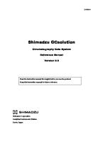
Figure 1-1: NAVIKNOT 450 D basic system overview
NAVIKNOT 450 D Electronics Unit with Master CDU
Accessories (optional) Remote CDU(s) NAVIKNOT 350 E
REMOTE
STW NAVIKNOT 350 E
12.8 kn
MASTER
STW
DAILY 1234.56 NM
12.8 kn DAILY 1234.56 NM
TOTAL 123456.7 NM
TOTAL 123456.7 NM
analogue repeaters
CDU type 5001
digital repeaters
10 5
X XXX X X X X X
15
0
20 -5
Speed
X XX X X X X XXX
X X X X X X X X X X X X
XXX X X X X X X X XXXXX X
XXXXX X X X X
XX
X
X
X X
X X
XX XX
X X X X X XXX X
X X X X X X XX X X XX X
X XX XX X X X XX X
25
electronics unit type 5003 to/from External Equipment
Analogue Output Serial Output Pulse Output Status Signals Out
Doppler Transducer and Electronics Unit
Status Signals In Ext. Speed (backup from GPS) Serial Dim Command
SRD 331 Doppler electronics unit
Doppler transducer
or
gate valve
tank mount
Figure 1-1 shows a basic system overview with the NAVIKNOT 450 D Electronics Unit, a Control and Display Unit (CDU) of type 5001 or 5002 and the Doppler transducer (gate valve or tank mount) with the SRD 331 Electronics Unit. Up to three additional remote CDUs may be connected to the electronics unit.
Central Alarm Management The NAVIKNOT 450 D system complies with the DNV rules for classification of ships requirement regarding a serial interface for the presentation and acknowledgement of alarms and warnings by an Alarm Management System (AMS) / Central Alarm Management (CAM). For details regarding the CAM interface settings see "Serial Data Alarm Management" on page 3-4, the "Service Setup – Parameters" in the "Service Setup Menu" and the NAVIKNOT CAMS Interface setting standard connection drawing 5002-0153-90 in the appendix.
Design and Main Features
1-3
056346/C
NAVIKNOT 450 D
Data Outputs The Electronics Unit receives raw speed data from the SRD 331 Electronics Unit and applies any necessary corrections according to a stored calibration table. The unit then transmits the calibrated water speed to receiving equipment and to the connected CDUs. It also calculates the distance travelled and maintains the total and daily mile counters. Serial speed and distance data is provided in the NMEA 0183 / IEC 61162 format at six RS-422 outputs. These are divided into two groups of three outputs each, which may be configured independently to suit the receiving equipment. Analogue speed signals are provided at one voltage and one current output. The mapping of actual speeds to corresponding output values is configured for each output independently. The distance travelled is also provided as a pulse signal at six contact closure outputs. These are divided into three groups of three, two and one output respectively, which may be configured independently to provide 10, 100, 200, 400 or 20000 pulses per nautical mile.
1-4
Design and Main Features
NAVIKNOT 450 D
056346/C
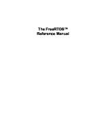
1.3 Operating Principle The NAVIKNOT 450 D system utilizes the principle of Doppler-shifted sound waves to determine the vessel’s speed relative to the water along the longitudinal (forward-aft) axis. The sensing signals are high frequency sound pulses which are transmitted from a transducer mounted through a hull penetration. The transducer contains two transmitter/ receiver windows, which transmit and receive signals in the forward and aft directions respectively. The SRD 331 Electronics Unit generates the transmit pulses and detects the return echo from the water during the time between transmissions. A time delay between pulse transmission and detection of the return signal ensures that echoes are received from undisturbed water outside the boundary layer at the hull. The return signals are processed to determine the vessel’s fore/aft speed vector. The SRD 331 Electronics Unit transmits the sensed speed in a digital format to the NAVIKNOT Electronics Unit. Figure 1-2: Doppler log operating principle
transmit pulses, aft return echos, aft
longitudinal water speed
return echos, fore transmit pulses, fore
Operating Principle
1-5
056346/C
NAVIKNOT 450 D
1.4 Technical Data General Speed/Distance Ranges and Accuracies (as per specification of the Doppler transducer) measuring range
- 50 to + 50 kn
1 σ error of displayed speed for a period of five minutes (under good hydrostatic conditions, pitch angles < 5°)
± 1% or 0.1 kn
NAVIKNOT Electronics Unit, Type 5003 Environmental Requirements ambient temperature, operation
- 15° C – + 55 °C
ambient temperature, storage
- 25° C – + 70° C
protection grade
IP 23 to DIN EN 60529
environmental conditions / EMC
in accordance with IEC 60945
Power Supply supply voltage
24 VDC
max. ripple content
-10% – +20% Vpp
power consumption
5 W max.
Magnetic Clearance to standard magnetic compass
0.5 m
to steering magnetic compass
0.4 m
reduced, to standard magnetic compass
0.3 m
reduced, to steering magnetic compass
0.3 m
Dimensions and Weight
1-6
width
340 mm
height
250 mm
depth
100 mm
weight
4.0 kg
Technical Data
NAVIKNOT 450 D
056346/C
Data Inputs Doppler transducer speed data
NMEA 0183 / IEC 61162
Control and Display Unit data
NMEA 0183 / IEC 61162 (proprietary sentences)
ext. speed data (backup from GPS)
NMEA 0183 / IEC 61162
serial dimming command
NMEA 0183 / IEC 61162
Signal and Status Inputs double ended ferry mode
connection to P.Gnd via ext. contact, latching
ext. alarm acknowledge status (mute)
connection to P.Gnd via ext. contact, momentary, normally open
ext. dim+ ext. dim-
connection to P.Gnd via ext. contact, momentary, normally open
Data Outputs serial data RS-422 outputs, group 1 (3x)
NMEA 0183 / IEC 61162; all or selected subset of: longitudinal water speed distance travelled log status (proprietary sentence)
serial data RS-422 outputs, group 2 (3x)
NMEA 0183 / IEC 61162; all or selected subset of: longitudinal water speed distance travelled log status (proprietary sentence)
Signal and Status Outputs
Technical Data
analogue speed output, voltage
max. range -9.999 – 9.999 VDC; speed mapped to output voltage through definition of min. and max. speed/voltage pairs
analogue speed output, current
max. range 0 – 20 mA; speed mapped to output current through definition of min. and max. speed/current pairs
pulse outputs, group 1 (outputs 1,2 and 3)
10, 100, 200, 400 or 20000 p/nm
pulse outputs, group 2 outputs 4 and 5)
10, 100, 200, 400 or 20000 p/nm
pulse output 6
10, 100, 200, 400 or 20000 p/nm or ext. alarm mute
power failure/general alarm speed log failure alarm speed limit threshold alarm watch alarm acknowledge
potential-free relay contacts, each rated 30 VDC / 1.0 A, 100 VDC / 0.3 A, 125 VAC / 0.5 A;
1-7
056346/C
NAVIKNOT 450 D
NAVIKNOT 450 D Control and Display Units (CDU) CDU Type 5001, main CDU and 2x1 remote unit Environmental Requirements ambient temperature, operation
- 15° C – + 55° C
ambient temperature, storage
- 25° C – + 70° C
protection grade Stock No. 73506 installed in console frame Stock No. 73506 installed with seal in console panel Stock No. 73507 (in housing) environmental conditions / EMC Stock No. 73506, if installed in console frame Stock No. 73506, if installed with seal in console panel, and Stock No. 73507 (in housing)
IP 23 to DIN EN 60529 frontside IP 65 to DIN EN 60529 IP 65 to DIN EN 60529 in accordance with IEC 60945, equipment category “protected from the weather” equipment category “exposed to the weather”
Power supply supply voltage
24 VDC
max. ripple content
-10% – +20% Vpp
power consumption
4 W max.
Magnetic Clearance to standard magnetic compass
0.80 m
to steering magnetic compass
0.50 m
reduced, to standard magnetic compass
0.50 m
reduced, to steering magnetic compass
0.30 m
Dimensions and Weight Stock No. 73506 (for console mounting)
1-8
width
192 mm
height
96 mm
depth
44 mm; approx. 100 mm backward clearance from mounting surface required for connector cable
weight
2.4 kg
Technical Data
NAVIKNOT 450 D
056346/C
Dimensions and Weight Stock No. 79488 (Stock No. 73506 factory-assembled in console frame) frame width
223 mm
frame height
127 mm
Stock No. 73507 (in housing with bracket) width
256 mm
max. height (unit in vertical position)
155 mm
max. depth (unit in horizontal position)
116 mm
weight
3.2 kg
CDU Type 5002, main CDU and 3x1 remote unit Environmental Requirements ambient temperature, operation
- 15° C – + 55° C
ambient temperature, storage
- 25° C – + 70° C
protection grade, main CDU and 3x1 remote unit
IP 23 to DIN EN 60529
protection grade, 2x1 remote unit
PN 73506: frontside IP 65 to DIN EN 60529, if installed with seal in console panel; IP 23 if installed in console frame PN 73507 (in housing with bracket): IP 65 to DIN EN 60529
environmental conditions / EMC
in accordance with IEC 60945
Power supply supply voltage
24 VDC
max. ripple content
-10% – +20% Vpp
power consumption
14 W max.
Magnetic Clearance
Technical Data
to standard magnetic compass
0.70 m (3x1 unit) 0.80 m (2x1 unit)
to steering magnetic compass
0.40 m (3x1 unit) 0.50 m (2x1 unit)
reduced, to standard magnetic compass
0.45 m (3x1 unit) 0.50 m (2x1 unit)
1-9
056346/C
NAVIKNOT 450 D
Magnetic Clearance reduced, to steering magnetic compass
0.30 m (3x1 unit) 0.30 m (2x1 unit)
Dimensions and Weight PN 73508 (for console mounting) width
192 mm
height
96 mm
depth
43 mm; approx. 120 mm backward clearance from mounting surface required for connector cable and plug
weight
2.4 kg
PN 79489 (PN 73508 factory-assembled in console frame) frame width
319 mm
frame height
127 mm
PN 73509 (in housing with bracket)
1-10
width
350 mm
max. height (unit in vertical position)
150 mm
max. depth (unit in horizontal position)
130 mm
weight
3.2 kg
Technical Data
NAVIKNOT 450 D
056346/C
SRD 331 Electronics Unit Environmental Requirements ambient temperature, operation
–15 to +55 °C
protection grade
IP 52 to DIN EN 60529
environmental conditions / EMC
in accordance with IEC 60945
Power Supply supply voltage
230 or 115 VAC
power consumption
40 W max.
Dimensions and Weight width
378 mm
height
292 mm
depth
216 mm
weight
9.7 kg approx.
Doppler Transducers Common Operational Data
Technical Data
speed range
- 50 to + 50 kn
radiated power (electrical)
10 W max.
signal mode
pulse
frequency
2 MHz
number of beams
2
beam width
1.5°
beam angle
15° from vertical
minimum required bottom clearance
1.8 m
1-11
056346/C
NAVIKNOT 450 D
Transducer with Gate Valve transducer for steel or aluminium vessels, single bottom
installation method
from inside vessel, through hull fittings
ambient temperature, operation
- 2 to + 40° C
protection grade
IP 68 to DIN EN 60529; submersible to 35 m
cable length
18 m (PN 74893 / 5020-AA) or 40 m (PN 74894 / 5020-AB) or 60 m (PN 74895 / 5020-AC)
dimensions and weight
see drawings 4983-0112-01 and 5020-0112-01
Tank Mount Transducer transducer for steel vessels, single or double bottom
installation method
from outside vessel; transducer can be exchanged without drydocking by a diver
ambient temperature, operation
- 2 to + 40° C
protection grade
IP 68 to DIN EN 60529; submersible to 35 m
cable length
40 m (PN 025832) or 60 m (PN 025833)*
dimensions and weight
see drawing 4978-0112-01
* The previous tank mount transducers of cable length 18 m (073497), 25 m (073498) and 36 m (073499) are deprecated.
1-12
Technical Data
NAVIKNOT 450 D
056346/C
1.5 Declaration of Conformity Marine Equipment Directive EC Declaration of Conformity: Northrop Grumman Sperry Marine B.V. Woltmanstrasse 19 D-20097 Hamburg, Germany. as manufacturer hereby declares that the following specified equipment: “NAVIKNOT 450 D Speed and Distance Measuring Equipment (SDME), single-axis Doppler water speed log system” complies with the Marine Equipment Directive 96/98/EC, as amended. This equipment has been tested to verify compliance with the Regulations and Testing Standards as per EC Type Examination (B) and EC Quality System (D) issued by: Notified Body No. 0098 Germanischer Lloyd. Note
The current issue of the detailed Marine Equipment Directive EC Declaration of Conformity of Northrop Grumman Sperry Marine B.V. Hamburg is part of the client CD stock no. 56 800. For further details please contact: Northrop Grumman Sperry Marine B.V. Hamburg Regulatory Support Group
Declaration of Conformity
1-13
056346/C
1-14
NAVIKNOT 450 D
Declaration of Conformity
NAVIKNOT 450 D
056346/C
Chapter 2: Operation 2.1 Display and Operating Keys Figure 2-1:
2
1
5
6
7
9
8
10
NAVIKNOT 450 D operating unit NAVIKNOT 450 D
MASTER
STW
12.8 kn DAILY 1234.56 NM
3
TOTAL 123456.7 NM
4
Display 1
Speed Display: Shows the actual speed through the water along the vessel’s longitudinal axis (fore-and-aft line). Arrow pointing up, above value: speed is positive (ahead). Arrow pointing down, below value: speed is negative (astern).
2
Mode Indicator: indicates the operating mode (Master or Repeater).
3
Alarm Display Area: In case of pending alarms, the alarm code(s) and error messages are shown in this area.
4
Mile Counters: Show the distance travelled since last reset (daily miles) and total cumulative distance travelled (total miles).
Operating Keys 5
ACK key: Acknowledge pending alarms; mute alarm buzzer.
6
MENU key: Call up or quit the menu mode.
7
MASTER key: Requests Master operating mode for this unit.
8
Navigation Keypad: UP, DOWN, LEFT, RIGHT: keys navigate through the operating menu; ENTER confirms and stores settings made in the menu mode. In case active alarms are present, the left and right arrow keys scroll through the list of alarm messages.
9?AT DIM– / DIM+: Adjust the display brightness.
Display and Operating Keys
2-1
056346/C
NAVIKNOT 450 D
2.2 External control devices Depending on the installation, external devices may be present to remotely control certain functions of the NAVIKNOT 450 D: •
The audible alarm at the NAVIKNOT 450 D may be muted from a remote device, e.g. a central alarm panel.
•
External pushbuttons may be used to adjust the display brightness.
•
If connected to a central dimming facility, the NAVIKNOT 450 D may receive dimming commands via a serial data connection.
•
An external selector switch may be used to activate or de-activate the double-ended ferry mode. In this mode, the NAVIKNOT 450 D displays and transmits all speeds with the sign reversed.
2.3 Power-up Sequence The separate components of the NAVIKNOT system are not equipped with power switches. All devices power up simultaneously, as soon as supply power is applied to the system. Upon power up, the startup routine is executed: The startup screen is shown and a system test sequence is executed.
NAVIGAT NN.NN
System Test NAVIKNOT 450 D
MASTER
STW
12.8 kn DAILY 1234.56 NM
Note
2-2
TOTAL 123456.7 NM
A status line at the bottom of the screen indicates the progress and results of the following tests: RAM test I/O test Checksum test Setup Data test After the system test, the indication “waiting for main unit” may be briefly shown at the CDU, while the Electronics Unit initializes itself. As soon as the system is fully operational, the actual speed and the daily and total mile counters are displayed.
Should the NAVIKNOT electronics fail to establish communication with the CDU(s) after power-up, the indication “waiting for main unit” will be shown permanently at all connected CDUs. An audible alarm is sounded which must be locally acknowledged at each CDU. The NAVIKNOT system will not operate properly until the cause of failure is eliminated and should be powered down until it can be serviced.
External control devices
NAVIKNOT 450 D
056346/C
2.4 Display Indications in Normal Operational Mode Speed Display
STW
12.8 kn
In the normal operational mode, the NAVIKNOT 450 D CDU permanently display the actual speed through the water (STW). An up-arrow symbol above the speed value indicates positive speeds (ahead), a down-arrow symbol below the value indicates negative speeds (astern). The value is displayed without sign.
Distance Counters DAILY 1234.56 NM
TOTAL 123456.7 NM
Also permanently displayed are the distance counters (daily and total mile counters). The counters display the distance made good through the water. The count is incremented at positive speeds only; counting is halted during zero or negative speeds.
Operating Status Indications Master/Remote status NAVIKNOT 450 D
MASTER
NAVIKNOT 450 D
REMOTE
Display Indications in Normal Operational Mode
The indication “MASTER” is shown in the top right corner of the CDU which currently the master unit. Other CDUs, if present, will show the indication “REMOTE”
2-3
056346/C
NAVIKNOT 450 D
Manual/External speed input active
Note
MAN
STW
EXTERN
STW
When the manual or external input mode has been activated in the manual settings menu, the indication “MAN” or “EXTERN” respectively is shown in the top left corner of the speed display.
CAUTION
Invalid speed and distance information in “Manual” mode of operation In case of failure of the Doppler transducer, the NAVIKNOT 450 D speed and distance information from the log are not valid and the system needs to become operated in the “Manual” or “Extern” mode of operation. The function of the “Manual” mode is to maintain normal operation of connected speed receivers, such as gyrocompasses, RADAR, ARPA etc., by transmitting valid output signals and data to the receiving equipment connected. Operating the NAVIKNOT 450 D system in the “Manual” mode may severely affect the appropriate function of all equipment which depend on accurate speed and/or distance data. Always make sure that the ship’s crew is aware of the fact that speed and distance information from the log are not valid, when operating the NAVIKNOT 450 D system in the “Manual” mode.
CAUTION
Invalid speed and distance information in “Extern” mode of operation In case of failure of the Doppler transducer, the NAVIKNOT 450 D speed and distance information from the log are not valid and the system needs to become operated in the “Manual” or “Extern” mode of operation. The function of the “Extern” mode is to maintain normal operation of connected speed receivers, such as gyrocompasses, RADAR, ARPA etc., by transmitting valid output signals and data to the receiving equipment connected. Operating the NAVIKNOT 450 D system in the “Extern” mode may severely affect the appropriate function of all equipment which depend on accurate longitudinal water speed data. Always make sure that the ship’s crew is aware of the fact that speed and distance information from the log are not valid and GPS ground speed data is displayed and transmitted as longitudinal water speed, when operating the NAVIKNOT 450 D system in the “Extern” mode. The “Extern” mode of operation can only be chosen, in case a GPS receiver is connected to the NAVIKNOT 450 D system. Speed not calibrated
UNCAL
2-4
kn
123456.7
When the transducer calibration table is empty or calibration has been switched off, the indication “UNCAL” is shown in the top right corner of the speed display.
Display Indications in Normal Operational Mode
NAVIKNOT 450 D
056346/C
2.5 Requesting Master Control In case more than one CDU is installed, only one of these can be assigned master control; all other CDUs will operate as remote units. Only from the master, the operator can access the operating and service menus, acknowledge alarms and scroll through the alarm list. Remote CDUs permanently display speed and distance. The only keys functional at a remote CDU are the DIM-/DIM+ keys to adjust the brightness level and the MASTER key, which requests master control to be transferred to this CDU. To request master control at a remote CDU:
Note
NAVIKNOT 450 D
REMOTE
NAVIKNOT 450 D
MASTER
Press the MASTER key. Master control is transferred and the mode indication changes from “REMOTE” to “MASTER”.
Master control can only be requested from a CDU which is currently operating as remote unit. The current master cannot actively transfer control to a remote CDU. Any remote CDU may request master control at any time, i.e. control requests cannot be refused by the current master.
2.6 Adjusting the display brightness The brightness of the display and keypad illumination is adjusted via the DIM+/DIM- keys: NAVIKNOT 450 D
MASTER
STW
12.8 kn kn DAILY 1234.56 NM
Note
Press the DIM+ key to increase the illumination brightness. Press the DIM- key to reduce the illumination brightness.
TOTAL 123456.7 NM
The display brightness can only be adjusted in normal operational mode. The brightness setting is not retained between power-ups. The NAVIKNOT 450 D always powers up at the second highest brightness level.
Requesting Master Control
2-5
056346/C
NAVIKNOT 450 D
2.7 Optional Functions The following functions may be available if the system is equipped with the respective external controls and configured accordingly.
Muting Alarms Remotely On alarm, actuate the mute control at a remote device (e.g. a central alarm panel). The audible alarm is muted. Note
A remotely muted alarm remains in the pending (unacknowledged) state. The alarm is indicated as pending in the alarm display area until the alarm is acknowledged at the NAVIKNOT 450 D or the cause of the alarm is eliminated.
Resetting/Acknowledging a Central Watch Alarm If connected to a central watch alarm facility ('dead man alarm'), the NAVIKNOT 450 D automatically resets the watch alarm timer whenever a key is pressed on the unit. Should a watch alarm be given, press any key at the NAVIKNOT 450 D to acknowledge the alarm and reset the watch alarm timer.
External Dimming If external DIM+/DIM- pushbuttons are installed, these operate in parallel with the builtin DIM+/DIM- keys. For future applications, the NAVIKNOT 450 D also possesses an input for serial data dimming commands from a central dimming facility.
Activating Double-Ended Ferry Mode In certain installations, a switch may be installed to activate or de-activate the double-ended ferry mode to transfer control between the forward and aft steering positions. If this mode is active, the speed indication at the display and within the transmitted messages VHW and VBW for water speed and ground speed is with their sign reversed. Note
The speed data within the VTG message (course over ground and ground speed), provided by GPS, is per definition always positive.
Note
In most installations where the double-ended ferry mode is used, it will be automatically activated via a general take-over system which transfers control between the forward and aft steering positions.
2-6
Optional Functions
NAVIKNOT 450 D
056346/C
2.8 Operating Menu The manual settings, user and service setup sub-menus are accessed through a multilevel operating menu.
Entering and Quitting the Menu Mode NAVIKNOT 450 D
From the normal operational mode, press MENU to enter the menu mode.
MASTER
STW MAIN MENU
12.8 kn >
The Main Menu screen is displayed. The keys of the navigation keypad may now be used to navigate the menu, to select parameter settings and to edit parameter values.
MANUAL SETTINGS USER SETUP 10° SERVICE SETUP
MAIN MENU
>
NAVIKNOT 450 D MANUAL SETTINGS USER SETUP SERVICE SETUP
>
MASTER
STW
12.8 kn 10°
Note
Operating Menu
From the main menu screen, press MENU to return to the normal operational mode. The Main Menu screen is closed and the normal operational display reappears.
In the menu mode, the MASTER and the DIM-/DIM+ keys are disabled. Should an alarm condition occur while the menu mode is active, the audible alarm will sound, but the operator must return to normal operational mode to view the alarm message and acknowledge the alarm.
2-7
056346/C
NAVIKNOT 450 D
Navigating the Menu In the menu mode, the operator may navigate through the menu using the Right, Left, Up and Down arrow keys. MAIN MENU XXXXXXXX MAIN MENU XXXXXXXX MAIN MENU XXXXXXXX XXXXXXXX YYYYYYYY YYYYYYYY YYYYYYYY XXXXXXXX MAIN MENU YYYYYYYY XXXXXXXX YYYYYYYY ZZZZZZZZ ZZZZZZZZ ZZZZZZZZ
MAIN MENU XXXXXXXX AAAAAAAA BBBBBBBB CCCCCCCC AAAAAAAA BBBBBBBB CCCCCCCC AAAAAAAA BBBBBBBB CCCCCCCC
MAIN MENU XXXXXXXX YYYYYYYY ZZZZZZZZ MAIN MENU XXXXXXXX YYYYYYYY MAIN MENU XXXXXXXX
2-8
Arrow symbols (>) to the right of the window indicate that a sub-menu exists for the respective option. Press ENTER to enter a submenu.
The arrow symbol (>) at the left of the window indicates the cursor position on the current menu level. With the Up/Down arrow keys, move to the cursor to the required sub-menu position.
Press the Left arrow key to return to the next higher menu level. Alternatively, MENU may be pressed to jump as high up as possible from the current level. In most cases, this will quit the menu immediately and return to normal operational mode.
Operating Menu
NAVIKNOT 450 D
056346/C
Selecting Parameter Settings In a number of sub-menus, the operator is expected to select parameter settings from a list of available options. The available options and the current selection are indicated by different symbols: Radio buttons: Allow to select exactly one of the available options. : selected : deselected Checkboxes: Allow to select or activate none, one or more of the available options. : selected : deselected To select parameter settings in a sub-menu: OPTIONS OPTIONS OPTION A OPTION B OPTION C OPTION A OPTION B OPTION C OPTION A OPTION B OPTION C
With the Up/Down arrow keys, move to the required option. Press ENTER to confirm the selection and leave the option sub-menu. MENU leaves the option submenu without changes.
Editing Parameter Values In a number of sub-menus, parameters are set by editing a numerical value or an alphanumerical string. To edit a parameter value in the respective sub-menu: VALUE VALUE: 00000
10000
10000 VALUE
With the Up/Down arrow keys, edit the character at the current cursor position. With the Right/Left arrow keys, move the cursor forward/back to edit the next/ previous character. Press ENTER to confirm the new value and leave the option sub-menu. MENU leaves the option submenu without changes.
Operating Menu
2-9
056346/C
NAVIKNOT 450 D
Caption for Selecting and Editing Figure 2-2 shows the caption for the different selecting and editing symbols used in all menus and submenus. Figure 2-2: Caption for choice, selecting and editing
SERVICE SETUP 1 û F1 SUBMENU 1 F2 SUBMENU 2 F3 SUBMENU 3 ü
SUBMENU 1 CHOICE A CHOICE B
2-10
Choice = “A” OR “B”
SUBMENU 2 SELECTION A SELECTION B SELECTION C
functionality of submenu 2
SUBMENU 3
functionality of submenu 3
EDITING OF NUMERIC VALUES e.g.: Note
functionality of submenu 1
Cumulative Selection = “A” and/or ”B” and/or “C”
Editing with: ûü / +0,1 – 9,9 sec
Choice means that either “A” or “B” must be chosen. Selection means that “A” and/or “B” can be selected cumulatively. Editing means that numeric values must be edited.
Operating Menu
NAVIKNOT 450 D
056346/C
2.9 Manual Settings Menu CAUTION
Invalid speed and distance information in “Manual” mode of operation In case of failure of the Doppler transducer, the NAVIKNOT 450 D speed and distance information from the log are not valid and the system needs to become operated in the “Manual” or “Extern” mode of operation. The function of the “Manual” mode is to maintain normal operation of connected speed receivers, such as gyrocompasses, RADAR, ARPA etc., by transmitting valid output signals and data to the receiving equipment connected. Operating the NAVIKNOT 450 D system in the “Manual” mode may severely affect the appropriate function of all equipment which depend on accurate speed and/or distance data. Always make sure that the ship’s crew is aware of the fact that speed and distance information from the log are not valid, when operating the NAVIKNOT 450 D system in the “Manual” mode.
CAUTION
Invalid speed and distance information in “Extern” mode of operation In case of failure of the Doppler transducer, the NAVIKNOT 450 D speed and distance information from the log are not valid and the system needs to become operated in the “Manual” or “Extern” mode of operation. The function of the “Extern” mode is to maintain normal operation of connected speed receivers, such as gyrocompasses, RADAR, ARPA etc., by transmitting valid output signals and data to the receiving equipment connected. Operating the NAVIKNOT 450 D system in the “Extern” mode may severely affect the appropriate function of all equipment which depend on accurate longitudinal water speed data. Always make sure that the ship’s crew is aware of the fact that speed and distance information from the log are not valid and GPS ground speed data is displayed and transmitted as longitudinal water speed, when operating the NAVIKNOT 450 D system in the “Extern” mode.
Note
The “Extern” mode of operation can only be chosen, in case a GPS receiver is connected to the NAVIKNOT 450 D system. The Manual Settings menu provides access to settings which the operator may need to alter more or less frequently during normal operation.
Manual Settings Menu
2-11
056346/C
NAVIKNOT 450 D
Manual Settings – Overview Figure 2-3: Manual Settings
MAIN MENU MANUAL SETTINGS >
SPEED MODE STW
>
SPEED MODE STW
speed data input mode
MAN SENSOR EXTERN
>
MAN SPEED VALUE
>
MAN SPEED VALUE
manual input value
RANGE: -99 – 99 KN
>
TRANSDUCER ON/OFF
TRANSDUCER ON/OFF
transducer on/off setting
Transducer mode for Preamplifier D; settings have no effect in systems with the SRD 331 Doppler Electronics Unit
2-12
Manual Settings Menu
NAVIKNOT 450 D
056346/C
Manual Settings – Parameters SPEED MODE STW Selects the speed input mode. Settings:
MAN (Manual) The actual speed value is entered manually. This setting may be chosen only temporarily, to generate speed output data in case of transducer failure or for testing. SENSOR Speed data is read from the speed sensor input, i.e. from the Doppler preamplifier. This setting must be active at all times during normal operation of the system.
Settings (contd.):
EXTERN Speed data is read from the NMEA $--VTG sentence at one of the NMEA inputs 1 or 2. This setting allows to use speed data from a GPS instead of manual input. Note that, while the $--VTG sentence contains ground speed, the NAVIKNOT 450 D displays and transmits the data as water speed. The external input may therefore be chosen only temporarily, to generate output data in case of transducer failure or for testing.
MAN (Manual) SPEED VALUE Sets the input value in the manual input mode. Settings:
RANGE: -99.9 – 99.9 KN Default value: + 12
TRANSDUCER ON/OFF Switches the transmit circuits on or off in systems equipped with the Preamplifier D, Type 5005. Settings:
Manual Settings Menu
Settings are not effective in systems equipped with the SRD 331 Doppler Electronics Unit.
2-13
056346/C
NAVIKNOT 450 D
2.10 User Setup The User Setup menu provides access to settings which the operator may need to alter only occasionally.
User Setup – Overview Figure 2-4: User Setup
MAIN MENU USER SETUP >
DAMP. TIME DISPLAY
>
DAMP. TIME DISPLAY RANGE: 0 – 60 SEC
>
DAMP. TIME OUTPUT
>
DAMP. TIME OUTPUT RANGE: 0 – 60 SEC
>
RESET DAILY MILES
damping time constant for speed display
damping time constant for speed outputs
>
RESET DAILY MILES reset counter to zero when user setup is quit
>
TOTAL MILES COUNTER
daily miles counter reset
>
TOTAL MILES COUNTER WATER START VALUE
total miles counter start value
RANGE: 0.0 – 999999.9 NM
>
LCD COLOR
>
LCD COLOR
screen colour scheme
WHITE BLUE BLACK
contd. on next page
2-14
User Setup
NAVIKNOT 450 D
056346/C
Figure 2-5:
contd. from previous page
User Setup (contd.)
>
SCALE
>
SCALE
speed display units
SPEED SCALE KN M/S FT/S
>
SOFTWARE VERSION NN.NN
SOFTWARE VERSION version ID (read-only)
User Setup
NAVIKNOT EU software version
2-15
056346/C
NAVIKNOT 450 D
User Setup – Parameters DAMP. (Damping) TIME DISPLAY Sets the damping time constant for the speed display. The higher the time constant, the stronger sudden peaks of the actual speed display will be damped. Settings:
RANGE: 0 – 60 SEC Default value: 04
DAMP. (Damping) TIME OUTPUT Sets the damping time constant for the speed outputs. The higher the time constant, the stronger sudden peaks of the actual speed output will be damped. The output damping time constant is effective for both the analogue as well as the serial data outputs. Settings:
RANGE: 0 – 60 SEC Default value: 04
RESET DAILY MILES Sets the reset flag for the daily miles counter. If the reset flag is set, the daily miles counter is reset to zero as soon as the User Setup is quit. Settings:
ON (option checked) Reset daily miles counter when User Setup is quit OFF (option unchecked) Leave daily miles counter untouched
TOTAL MILES COUNTER WATER START VALUE Sets the water speed total miles counter to a desired start value. Settings:
RANGE: 0.0 – 999999.9 NM
Note
The water speed total miles counter may be set to any desired start value. The daily mile count may thus be larger than the total mile count if the daily miles counter is not reset after altering the total mile counter.
2-16
User Setup
NAVIKNOT 450 D
056346/C
LCD COLOR Selects the screen colour scheme for the normal operational display. Settings:
WHITE Speed display and mile counters use black lettering on a white background. BLUE Speed display and mile counters use white lettering on a blue background. BLACK Speed display and mile counters use white lettering on a black background.
SCALE SPEED SCALE Selects the unit of measure for the speed display. The respective setting acts on the actual speed display at the CDU only and has no further effect on the output data, mile counters etc. Settings:
KN Speed is displayed in knots. M/S Speed is displayed in metres per second. FT/S Speed is displayed in feet per second.
SOFTWARE VERSION Displays the software version of the NAVIKNOT Electronics Unit. Settings:
User Setup
none The version ID is read-only.
2-17
056346/C
2-18
NAVIKNOT 450 D
User Setup
NAVIKNOT 450 D
056346/C
Chapter 3: Alarm System 3.1 Alarm Indication Audible Alarm Indication Single Beep: Invalid Action A single short beep indicates that the operator attempted to carry out an invalid action. This is the case e.g. if the operator attempts to enter the menu from a remote unit.
Continuous Beeping: Pending Alarm Continuous on-off beeping indicates that a pending (unacknowledged) alarm is present. Simultaneously, a corresponding alarm message is shown in the alarm window.
Visual Alarm Indication If an alarm is active, a messages is shown in the alarm display area (above the mile counters) which specifies the alarm at hand. Active alarms have one of two possible states:
< (1/1) SRD TIMEOUT >
< (1/1) SRD TIMEOUT >
Alarm Indication
Pending (unacknowledged): The cause of the alarm is present and the operator has not yet acknowledged the alarm. The alarm message is shown on a red flashing background. Acknowledged: The operator has acknowledged the alarm but the cause of the alarm is still present. The alarm message is shown on a solid red background.
3-1
056346/C
NAVIKNOT 450 D
3.2 Acknowledging Alarms/Muting the Audible Alarm Local Alarm Acknowledge To acknowledge a pending alarm at the NAVIKNOT 450 D CDU: Press ACK. The audible alarm indication is muted. < (1/1) SRD TIMEOUT >
If the system is connected to a central alarm facility and configured accordingly, the audible alarm indication at the central alarm facility will also be muted. < (1/1) SRD TIMEOUT >
Note
When an alarm has been acknowledged, the ext. alarm status output remains active until the cause of the alarm is eliminated. When the cause of an alarm is eliminated, the alarm is acknowledged automatically and the alarm status is cleared. The NAVIKNOT 450 D does not keep a history of past (inactive) alarms.
External Alarm Mute To mute the audible alarm externally (e.g. from a central alarm panel): Actuate the external mute facility. The audible alarm indication is muted. < (1/1) SRD TIMEOUT >
ext. alarm m ute
The alarm state and visible indication are not affected, i.e. the alarm remains in the pending state until it is locally acknowledged at the NAVIKNOT 450 D CDU.
< (1/1) SRD TIMEOUT >
3-2
Acknowledging Alarms/Muting the Audible Alarm
NAVIKNOT 450 D
056346/C
3.3 Viewing the active alarms The total number of alarms and the index number of the currently displayed alarm are shown in front of the alarm message. If more than one alarm is active, use the Left or Right arrow key to scroll through the list of alarm messages:
< (1/3) SENSOR ERROR > < (2/3) SENSOR ERROR > < (3/3) SRD TIMEOUT >
Note
Viewing the active alarms
As long as any pending (unacknowledged) alarms are present, these will automatically be redisplayed when other messages have been viewed, until all alarms have been acknowledged by the operator.
3-3
056346/C
NAVIKNOT 450 D
3.4 Serial Data Alarm Management The NAVIKNOT 450 D system complies with the DNV rules for classification of ships requirement regarding a serial interface for the presentation and acknowledgement of alarms and warnings by an Alarm Management System (AMS) / Central Alarm Management (CAM). The NAVIKNOT 450 D system supports the external alarm handling using the $--ALR (set alarm state) and $--ACK (acknowledge alarm) sentences according to IEC 61162 (NMEA 0183). If transmission of the $--ALR sentence is enabled, the active alarms may be displayed at an external alarm handling device or may be recorded by a VDR. If reception of the $--ACK sentence is enabled, pending alarms may be acknowledged from the external alarm handling device. The $--ALR and $--ACK sentences are implemented as follows:
3-4
•
When no alarm conditions are present, the NAVIKNOT 450 D transmits a “no alerts” message as recommended per IEC 80/520/INF, once per second. This is an $--ALR sentence with null fields for the alarm code and description.
•
When the NAVIKNOT 450 D raises an alarm, an $--ALR sentence, containing the corresponding alarm number and description text is transmitted once per second. The alarm will be marked as “active” and “not acknowledged”. In case of multiple alarms, the corresponding $--ALR sentences are transmitted in turn, one sentence per second.
•
If a pending alarm is acknowledged (locally or through an $--ACK sentence), the NAVIKNOT 450 D marks the respective $--ALR sentence as “acknowledged”.
•
When an alarm condition clears, regardless of whether the operator has acknowledged the alarm or not, the NAVIKNOT 450 D transmits the respective $--ALR sentence five times with status ”acknowledged”. Then, the device stops transmitting the sentence in question.
Serial Data Alarm Management
NAVIKNOT 450 D
056346/C
3.5 Error Messages Table 3-1: Error messages
Note
Error Messages
message text
cause
corrective action
WAITING FOR MAIN UNIT (shown on startup screen)
Communication between electronics unit and CDU(s) could not be established
Check operation of the electronics unit; Check cabling between CDU and electronics unit. If error persists, power down the system and call service.
SRD TIMEOUT
Transducer protocol detection failed
SRD 331 TIMEOUT
Data lost from SRD 331 electronics unit (protocol detection succeeded and valid data was received previously)
Check that the SRD 331 electronics unit is operating; check that protocol is set to NMEA; check cabling between SRD 331 and NAVIKNOT electronics unit; check cabling between transducer and SRD 331 electronics unit; check transducer for proper operation.
SCAN SENSOR
Transducer protocol detection running (NAVIKNOT electronics unit analyzes incoming data)
Error is cleared once transducer protocol has been determined. If error persists, check preamplifier D for proper operation.
EXT DIM TIMEOUT
No valid commands received at serial dim input.
Check connection between dimming device and electronics unit.
EU TIMEOUT
Communication lost between electronics unit and CDU
Check basic operation of the electronics unit (valid output generated at serial data / analogue outputs); Check cabling between CDU and electronics unit.
In case of an “EU timeout” error, dashes will appear in the speed and distance displays. The timeout error will be shown as the only fault present, because the CDU receives no error messages from the electronics unit when the communication is lost.
3-5
056346/C
3-6
NAVIKNOT 450 D
Error Messages
NAVIKNOT 450 D
056346/C
Chapter 4: Scheduled Maintenance 4.1 Maintenance by Shipboard Personnel NAVIKNOT Electronics Unit and CDU The electronic components of the NAVIKNOT 450 D system are solidstate devices and contain no consumable parts. Therefore, no set maintenance schedule is required. The CDU front plate should be kept clean and a regular visual inspection of the system’s cables and connectors should be carried out to detect any signs of damage or deterioration. CAUTION
Risk of damage The CDU front plate is made of clear polycarbonate. Do not clean the front plate with organic solvents, acetone or any other substance which could damage or discolour plastic. Use only water and soap or a mild detergent to clean the front plate.
Doppler Transducer Maintenance Depending on the type of transducer installed, certain maintenance procedures are to be carried out at regular intervals, such as cleaning of the transducer face and lubrication/overhaul of the gate valve, if applicable. The recommended maintenance schedule and procedures are described in the installation, maintenance and service instructions for the Doppler transducers and electronics unit, document no. 004909-0125-001.
Maintenance by Shipboard Personnel
4-1
056346/C
4-2
NAVIKNOT 450 D
Maintenance by Shipboard Personnel
NAVIKNOT 450 D
056346/C
Chapter 5: Installation 5.1 Mechanical Installation Doppler Transducer and SRD 331 Electronics Unit Details of the installation and dimension/installation drawings for the Doppler transducers and the SRD 331 electronics unit, are contained in the installation, maintenance and service instructions for the Doppler transducers and SRD 331 electronics unit, document 004909-0125-001, and in the dimension/installation drawing for the respective transducer. In general, field service will attend a vessel after the transducer hardware has been installed mechanically by the shipyard. I.e., in case of the gate valve transducer, the gate valve will be installed and in case of the tank mount transducer, the cofferdam tank and transducer will be installed completely. In most cases, the vessel will be afloat at this point in time. The SRD 331 electronics unit may be installed at the same time as the transducer or later, together with the other electronic components of the NAVIKNOT 450 D system.
NAVIKNOT Electronics Unit The electronics unit is to be installed at a protected location. In most cases, it will be mounted in the vicinity of the master CDU. The electronics unit is to be attached to a level surface with four M6 screws (or nuts and bolts). For the dimensions of the housing, refer to drawing 5003-0112-01. The electronics unit may be installed vertically, horizontally or inclined.
Mechanical Installation
5-1
056346/C
NAVIKNOT 450 D
Control and Display Units Console Mounting To mount a NAVIKNOT CDU directly in a console panel (without console frame), a panel cutout is required as shown in the respective drawings (see Appendix). Suitable fasteners for console mounting are provided in the installation kit 22724, included with the CDU, type 5001, respectively type 5002. A backward clearance of approx. 100 mm from the mounting surface is required to protect the connector cable from being bent too strongly at the cable gland. Console Frame Version When ordered factory-assembled in a console frame, the NAVIKNOT CDUs, type 5001 or 5002, are already fastened to the frame. The required cutouts for a standard 2x1 frame are shown in drawing 0012-0112-02, respectively 5002-0112-02 (see Appendix). If a custom frame is delivered, installation-specific dimensional drawings for the frame and cutout will be provided with the equipment. A backward clearance of approx. 90 mm from the frame top surface is required to protect the connector cable from being bent too strongly at the cable gland. Housing with Bracket The NAVIKNOT CDU, type 5001, in housing with bracket is shown in dimensional drawing 5001-0112-02 (see Appendix). The mounting bracket carries four holes of 5.3 mm dia. for fixing the bracket to any plane surface, such as a console panel, wall or ceiling. The required fasteners are to be provided by the shipyard or installer. The NAVIKNOT CDU, type 5002, in housing with bracket is shown in dimensional drawing 5002-0112-01 (see Appendix). Connector Cable The NAVIKNOT CDU connector cable terminates into a 6-wire pigtail for direct connection to the terminals at the Electronics Unit or to a separate terminal block. If required, a terminal block is to be provided by the shipyard or installer. The installer must make sure that the end of the cable sheath is firmly secured to the vessel structure with tie-wraps or other suitable means, so that the individual wires are free from tension at the terminals.
5-2
Mechanical Installation
NAVIKNOT 450 D
056346/C
5.2 Electrical Installation SRD 331 Electronics Unit, AC Power Configuration The SRD 331 electronics unit is delivered prewired for connection to 230VAC. If the unit is required to operate on 115 VAC, it must be reconfigured accordingly. Details of the AC power configuration are contained in the installation, maintenance and service instructions for the Doppler transducers and SRD 331 electronics unit, document no. 004909-0125-001.
Wiring Up the System DANGER
Life danger through electrical shock Hazardous voltages are present at certain terminals and tracks on the SRD 331 electronics unit, when the AC supply power is switched on. Danger of electrical shock or burn when terminals and tracks on the SRD 331 electronics unit are touched while AC power is applied. Never touch the SRD 331 electronics unit terminals and tracks and connect or disconnect cabling while AC power is applied.
WARNING
Risk of electrical shock When wiring up the system, accidental switching-on of the AC supply power will energize the system. Always make sure that the power supply for the NAVIKNOT system is switched off and is safeguarded against accidental switching-on, when wiring up the system.
CAUTION
Risk of damage Components on the devices’ PCBs are sensitive to static discharge. Electrostatic discharge may permanently damage components. Take the necessary precautions to prevent electrostatic discharges. Avoid touching any of the electronic circuitry. Wire up the system according to the connection diagrams and other relevant documents provided. If installation-specific connection diagrams have been provided for a given system, these supersede any connection information contained in standard connection diagrams. If wiring up according to standard connection diagrams, make sure beforehand that all data and signals to receive from or transmit to external equipment comply to the NAVIKNOT Electronics Unit interface specification, 5003-0120-001.
Electrical Installation
5-3
056346/C
NAVIKNOT 450 D
5.3 Initial System Configuration Configuring the CDU(s) If one CDU is installed only, the unit requires no further configuration. In case more than one CDU is installed, each CDU must be assigned a unique ID through its local Service Setup menu. CDU Setup Access Code To prevent inadvertent or unauthorized changes to the CDU configuration, the local setup menu is protected by an access codes To access the local CDU Service Setup: NAVIKNOT 450 D
MASTER
STW
+
12.8 kn
ENTER CODE 000
SERVICE SETUP
From the normal operational mode, simultaneously press ENTER and MENU to call up the CDU’s local Service Setup menu mode. When prompted for the setup code, enter code 600. The CDU’s local Service Setup opens.
CDU ID DIMMING
5-4
Initial System Configuration
NAVIKNOT 450 D
056346/C
CDU Service Setup – Overview Figure 5-1: CDU Service Setup
SERVICE SETUP
>
CDU ID
>
CDU ID
this CDU's local ID
RANGE: 0 – 9
>
DIMMING
>
DIMMING
settings for serial dimming
GROUP ID RANGE: 00 – 99
dim group ID assignment
CENTRAL DIMMING OFFSET RANGE: -7 – 7
DIM MIN VALUE RANGE: 0 – 999
brightness
DIM VALUE 2 RANGE: 0 – 999
brightness
. . . DIM VALUE 3 - 7 DIM MAX VALUE RANGE: 0 – 999
Initial System Configuration
brightness
5-5
056346/C
NAVIKNOT 450 D
CDU Service Setup – Parameters CDU ID Sets the CDU’s local ID. The ID serves to identify the individual CDUs in systems where one or more remote CDUs are installed. The electronics unit uses the ID to keep track of which CDU is currently assigned master command. Settings:
RANGE: 0 – 9 Default value: 0 Select an ID between “1” and “9” if more than one CDU is installed. A given ID may only be assigned to one CDU within the system. In a single-CDU system, select ID “0”.
DIMMING GROUP ID Assigns the CDU to a dim group. The ID setting is only effective if dimming commands are read from the proprietary NMEA sentence $PPLAI. Settings:
RANGE: 00 – 99 Default value: 00 Select an ID between “01” and “09” to assign the CDU to the respective dim group. Selecting ID “00” lets the CDU accept any dim command received, regardless of group assignment.
CENTRAL DIMMING OFFSET Sets a local offset for the brightness level. Settings:
RANGE: -7 – 7 Default value: 0 Select an offset as required to match the brightness of the CDU to that of other equipment controlled through the same dim command device. Offsets below 0 decrease, offsets above 0 increase the CDU’s overall brightness by the corresponding number of brightness levels. However, the offset will not alter the brightness beyond the min. and max. levels respectively. The factory default for the offset is 0.
5-6
Initial System Configuration
NAVIKNOT 450 D
056346/C
DIM VALUES (MIN VALUE - VALUE 2–7 - MAX VALUE) Maps the ordered brightness setting as read from the serial dim command to the CDU’s nine discrete brightness levels. Settings:
RANGE: 00 – 999 Default values: DIM MIN VALUE DIM VALUE 2 DIM VALUE 3 DIM VALUE 4 DIM VALUE 5 DIM VALUE 6 DIM VALUE 7 DIM MAX VALUE
000 200 260 320 400 500 750 950
For each brightness level, set the smallest intensity order at which the level should be active. If the order received is smaller than the set value, brightness is reduced to the next lower level.
Configuring System Parameters When the system has been wired up, all configuration parameters are to be set to the required values in the Service Setup in order to make the NAVIKNOT system fully functional. For a description of the Service Setup, refer to Chapter 6 (System Configuration). Note
As the first step in an initial system configuration, call up the Service Setup and the system type parameter to “NAVIKNOT 450 D“. Then, quit the setup menu and cycle the power to make sure that only those parameter settings and configuration options which apply to a NAVIKNOT 450 D system are available through the Service Setup. After the initial system configuration, note all settings in the NAVIKNOT 450 D system setup table (see Appendix). Send one copy of the filled-out table to Sperry Marine for inclusion in the ship’s file. The operating parameters in the User Setup and Manual Settings menus should also be set as required for normal operation within the given system.
Initial System Configuration
5-7
056346/C
5-8
NAVIKNOT 450 D
Initial System Configuration
NAVIKNOT 450 D
056346/C
Chapter 6: System Configuration 6.1 Service Setup Menu The Service Setup menu provides access to the system parameters which configure the NAVIKNOT 450 D according to the requirements of the installation at hand.
Setup Access Code To prevent inadvertent or unauthorized changes to the system configuration, setup menus which are to be accessed by service personnel only are protected by access codes. To access the Service Setup: MAIN MENU
Call up the Main Menu. Select the Service Setup.
SERVICE SETUP
ENTER CODE 000
When prompted for the setup code, enter code 600. Press ENTER to continue. Page 1 of the Service Setup opens.
SERVICE SETUP Page 1 NEXT PAGE (2) SYSTEM TYPE
Service Setup Menu
6-1
056346/C
NAVIKNOT 450 D
Service-Setup – Overview Figure 6-1: Service Setup, page 1
SERVICE SETUP Page 1
>
NEXT PAGE (2)
>
skip to page 2
>
ANALOG OUTPUT
>
ANALOG OUTPUT
settings for analogue speed outputs
VOLTAGE MINIMUM VOLTAGE RANGE: -9.999 – 9.999 V
output value at min. speed
MAXIMUM VOLTAGE RANGE: -9.999 – 9.999 V
output value at max. speed
MINIMUM SPEED RANGE: -99.9 – 99.9 KN
min. speed value
MAXIMUM SPEED RANGE: -99.9 – 99.9 KN
max. speed value
CURRENT MINIMUM CURRENT RANGE: 0.00 – 20.00 MA
output value at min. speed
MAXIMUM CURRENT RANGE: 0.00 – 20.00 MA
output value at max. speed
MINIMUM SPEED RANGE: -99.9 – 99.9 KN
min. speed value
MAXIMUM SPEED RANGE: -99.9 – 99.9 KN
max. speed value
contd. on next page
6-2
Service Setup Menu
NAVIKNOT 450 D
056346/C
Figure 6-2: Service Setup, page 1 (contd.)
contd. from previous page
>
PULSE OUTPUT 1-3
>
PULSE / NM
settings for pulse outputs 1-3
PULSE / NM 1–3 10 PULSE/NM 100 PULSE/NM 200 PULSE/NM 400 PULSE/NM 20000 PULSE/NM >
PULSE OUTPUT 4-5
>
PULSE / NM
settings for pulse outputs 4-5
PULSE / NM 4–5 10 PULSE/NM 100 PULSE/NM 200 PULSE/NM 400 PULSE/NM 20000 PULSE/NM >
PULSE OUTPUT 6
>
PULSE OUTPUT 6
settings for pulse output 6
PULSE / RELAY 10 PULSE/NM 100 PULSE/NM 200 PULSE/NM 400 PULSE/NM 20000 PULSE/NM MUTE RELAY >
RS422 OUTPUT 1-3
>
RS422 OUTPUT 1–3 MESSAGES NMEA 1–3 VBW VHW VLW VLW extended PPLAK ALR
settings for RS-422 outputs group 1 (outp.1-3)
BAUDRATE NMEA 1–3 4800 BAUD 9600 BAUD 38400 BAUD DATA LOGGER all data logging functions are for factory use only; do not alter settings or access menu unless instructed by Sperry Marine. contd. on next page
Service Setup Menu
6-3
056346/C
NAVIKNOT 450 D
Figure 6-3: Service Setup, page 1 (contd.)
contd. from previous page
>
RS422 OUTPUT 4-6
>
RS422 OUTPUT 4–6 MESSAGES NMEA 4–6 VBW VHW VLW VLW extended PPLAK ALR
settings for RS-422 outputs group 2 (outp.4-6)
BAUDRATE NMEA 4–6 4800 BAUD 9600 BAUD 38400 BAUD
>
NMEA INPUT 1
>
NMEA INPUT 1
settings for NMEA input 1
MESSAGES NMEA INP. 1 VTG ACK DDC PPLAI BAUDRATE NMEA INP. 1 4800 BAUD 9600 BAUD 38400 BAUD
>
NMEA INPUT 2
>
NMEA INPUT 2
settings for NMEA input 2
MESSAGES NMEA INP. 2 VTG ACK DDC PPLAI BAUDRATE NMEA INP. 2 4800 BAUD 9600 BAUD 38400 BAUD
6-4
Service Setup Menu
NAVIKNOT 450 D
Figure 6-4: Service Setup, page 2
056346/C
SERVICE SETUP Page 2
>
NEXT PAGE (1)
>
skip to page 1
>
SYSTEM TYPE
>
SYSTEM TYPE
system type configuration
NAVIKNOT 450D type must be set to 450D
>
SENSOR POLARITY
>
SENSOR POLARITY
EM-sensor polarity setting
NORMAL INVERSE >
RELAY SPEED LIMIT
>
RELAY SPEED LIMIT
relay output threshold values
MINIMUM VALUE RANGE: -99.9 – 99.9 KN MINIMUM VALUE ON
minimum threshold value
MAXIMUM VALUE RANGE: -99.9 – 99.9 KN MAXIMUM VALUE ON
maximum threshold value
contd. on next page
Service Setup Menu
6-5
056346/C
NAVIKNOT 450 D
Figure 6-5: Service Setup, page 2 (contd.)
contd. from previous page
>
CALIBRATION
>
CALIBRATION
sensor calibration settings
CAL. TABLE ON access calibration table entries
CALIBRATION TABLE CAL. TABLE
CAL.NO
300 4
UNCAL SPEED
-- . --
TRUE SPEED
-- . --
DELETE
NO
ZERO POINT
calibrate zero point (0 kn)
MAN CALIBRATION TRUE SPEED
+ nn.n KN
UNCAL SPEED + nn.n KN CAL VALUE
3 + -- . - 4+
AUTO CALIBRATION TRUE SPEED
+ nn.n KN
UNCAL SPEED + nn.n KN CAL VALUE
3 + -- . - 4+
TWO WAY TRIAL RUN TIME
00 : 00 S
SPEED
nn . nn KN
ONE WAY TRIAL RUN TIME
00 : 00 S
SPEED
nn . nn KN
initiate two way calibration trial run
initiate one way calibration trial run
contd. on next page
6-6
Service Setup Menu
NAVIKNOT 450 D
056346/C
Figure 6-6: Service Setup, page 2 (contd.)
contd. from previous page
>
PREAMPL D SETUP
>
PREAMPL D SETUP
Doppler preamplifier D setup
Test and diagnostic menu for preamplifier D; not applicable for systems with SRD 331 el. unit
>
NETWORK SETUP
>
NETWORK SETUP
network setup
for future use; not functional in current software release
Service Setup Menu
6-7
056346/C
NAVIKNOT 450 D
Service Setup – Parameters ANALOG OUTPUT Configures the analogue speed outputs (voltage and current output). VOLTAGE Configures the analogue output voltage range. The output voltage range is defined by two pairs of values: The minimum speed and associated minimum voltage determine the lower limit of the output range, while the maximum speed and associated maximum voltage define its upper limit. voltage
MAX
At speeds equal to or below the minimum speed, the output delivers the minimum voltage; at speeds equal or above the maximum speed, the output delivers the maximum voltage. Speeds in-between the minimum and maximum speed are linearly mapped to the corresponding output voltage.
MIN
speed
The absolute limits of the output are -9.999 V min. and 9.999 V max. Example: Moving coil speed indicators are to be used which are scaled from -5 kn at zero deflection to +25 kn at a full-scale deflection of 10 VDC. The required settings are: min. voltage = 0.000 V; min. speed = -5 kn; max. voltage = 9.999 V; max. speed = +25 kn Settings:
MINIMUM VOLTAGE RANGE: -9.999 – 9.999 VDC Default value: 0.000 MAXIMUM VOLTAGE RANGE: -9.999– 9.999 VDC Default value: +9.999 MINIMUM SPEED RANGE: -99.9 – +99.9 KN Default value: 00.00 IMAXIMUM SPEED RANGE: -99.9 – +99.9 KN Default value: +42.0
6-8
Service Setup Menu
NAVIKNOT 450 D
056346/C
CURRENT Configures the analogue output current range.
current
The output current range is defined by two pairs of values: The minimum speed and associated minimum current determine the lower limit of the output range, while the maximum speed and associated maximum current define its upper limit.
MIN
speed
MAX
At speeds equal to or below the minimum speed, the output delivers the minimum current; at speeds equal or above the maximum speed, the output delivers the maximum current. Speeds in-between the minimum and maximum speed are linearly mapped to the corresponding output current.
The absolute limits of the output are 0.00 mA min. and 20.00 mA max. Example: The speed range of -25 to +25 kn is to be mapped to a 4 – 20 mA output. The required settings are: min. current = 4.00 mA; min. speed = -25 kn; max. voltage = 20.00 mA; max. speed = +25 kn Settings:
MINIMUM CURRENT RANGE: 0.00 – 20.00 MA Default value: 00.00 MAXIMUM CURRENT RANGE: 0.00 – 20.00 MA Default value: 20.00 MINIMUM SPEED RANGE: -99.9 – +99.9 KN Default value: 00.0 MAXIMUM SPEED RANGE: -99.9 – +99.9 KN Default value: +42.0
Service Setup Menu
6-9
056346/C
NAVIKNOT 450 D
PULSE OUTPUT Configures the pulse signal outputs. The outputs are divided into three individually configurable groups. Each group may be configured to deliver 10, 100, 200, 400 or 20000 pulses per nautical mile. The generated pulses possess a fixed “on” duty cycle of 100 ms for the 10, 100 or 200 pulse/NM setting, 50 ms for the 400 pulse/NM setting and 1 ms for the 20000 pulse/NM setting. Group 3 (output 6) may alternatively be configured to generate an alarm mute signal. This signal, a 100 ms pulse, is used to mute the audible alarm indication at a central alarm facility when the respective alarm is acknowledged locally at the NAVIKNOT 450 D CDU. PULSE OUTPUT 1–3 PULSE / NM 1–3 Configures group 1 of the pulse outputs (outputs 1 – 3). Settings:
10 PULSE/NM The output delivers 10 pulses per nautical mile. 100 PULSE/NM The output delivers 100 pulses per nautical mile. 200 PULSE/NM The output delivers 200 pulses per nautical mile. 400 PULSE/NM The output delivers 400 pulses per nautical mile. 20000 PULSE/NM The output delivers 20000 pulses per nautical mile.
PULSE OUTPUT 4–5 PULSE / NM 4–5 Configures group 2 of the pulse outputs (outputs 4 – 5). Settings:
10 PULSE/NM The output delivers 10 pulses per nautical mile. 100 PULSE/NM The output delivers 100 pulses per nautical mile. 200 PULSE/NM The output delivers 200 pulses per nautical mile. 400 PULSE/NM The output delivers 400 pulses per nautical mile. 20000 PULSE/NM The output delivers 20000 pulses per nautical mile.
6-10
Service Setup Menu
NAVIKNOT 450 D
056346/C
PULSE OUTPUT 6 PULSE / RELAY Configures group 6 of the pulse outputs (output 6). Settings:
10 PULSE/NM The output delivers 10 pulses per nautical mile. 100 PULSE/NM The output delivers 100 pulses per nautical mile. 200 PULSE/NM The output delivers 200 pulses per nautical mile. 400 PULSE/NM The output delivers 400 pulses per nautical mile. 20000 PULSE/NM The output delivers 20000 pulses per nautical mile. MUTE RELAY When an alarm is acknowledged locally at the NAVIKNOT 450 D CDU, the output delivers a pulse to mute the audible alarm indication at a central alarm facility.
Service Setup Menu
6-11
056346/C
NAVIKNOT 450 D
RS422 OUTPUT 1–3 Configures group 1 of the RS-422 serial data outputs (outputs 1–3). MESSAGES NMEA 1–3 Selects the NMEA sentences to transmit. If the NAVIKNOT 450 D cannot provide valid data for an NMEA sentence field, a null field (empty field) is sent. Status fields for invalid or unknown data are marked as invalid (“V“). The Talker ID is ”VM” for all sentences except the proprietary $PPLAK. Settings:
VBW Longitudinal water speed and status (valid/invalid) are transmitted using the $--VBW sentence. VHW Longitudinal water speed is transmitted using the $--VHW sentence. VLW / VLW extended The distance travelled through the water since last reset (daily miles) and total cumulative water distance (total miles) are transmitted using the $--VLW sentence. The “extended” form of the sentence includes trailing fields for ground distances as per IEC 61162-1:2000, the noneextended form omits these fields. PPLAK Log status and operating mode information is transmitted using the proprietary $PPLAK sentence. ALR Information on alarm conditions and their acknowledgement state are transmitted using the $--ALR sentence. When no alarms are present, a “no alarm” message is transmitted cyclically, as recommended in IEC 80/520/INF.
CAM Interface Settings For the usage of the serial CAM interface the RS422 Output 1–3 or RS422 Output 4–6 needs to be set to ALR and the NMEA Input 1 or NMEA Input 2 needs to be set to ACK.
6-12
Service Setup Menu
NAVIKNOT 450 D
056346/C
BAUDRATE NMEA 1–3 Selects the transmit baudrate. Settings:
4800 BAUD Data is transmitted at 4800 Baud (standard according to NMEA / IEC 61162-1) 9600 BAUD Data is transmitted at 9600 Baud (non-standard) 38400 BAUD Data is transmitted at 38400 Baud (high-speed according to IEC 61162-2)
DATA LOGGER All access data logging functions are or factory use. Field service must not alter any setting and should not access this menu unless instructed by Sperry Marine.
Service Setup Menu
6-13
056346/C
NAVIKNOT 450 D
RS422 OUTPUT 4–6 Configures group 2 of the RS-422 serial data outputs (outputs 4–6). MESSAGES NMEA 4–6 Selects the NMEA sentences to transmit. If the NAVIKNOT 450 D cannot provide valid data for an NMEA sentence field, a null field (empty field) is sent. Status fields for invalid or unknown data are marked as invalid (“V“). The Talker ID is ”VM” for all sentences except the proprietary $PPLAK. Settings:
VBW Longitudinal water speed and status (valid/invalid) are transmitted using the $--VBW sentence. VHW Longitudinal water speed is transmitted using the $--VHW sentence. VLW / VLW extended The distance travelled through the water since last reset (daily miles) and total cumulative water distance (total miles) are transmitted using the $--VLW sentence. The “extended” form of the sentence includes trailing fields for ground distances as per IEC 61162-1:2000, the none-extended form omits these fields.
PPLAK Log status and operating mode information is transmitted using the proprietary $PPLAK sentence. ALR Information on alarm conditions and their acknowledgement state are transmitted using the $--ALR sentence. When no alarms are present, a “no alarm” message is transmitted cyclically, as recommended in IEC 80/520/INF.
CAM Interface Settings For the usage of the serial CAM interface the RS422 Output 1–3 or RS422 Output 4–6 needs to be set to ALR and the NMEA Input 1 or NMEA Input 2 needs to be set to ACK.
6-14
Service Setup Menu
NAVIKNOT 450 D
056346/C
BAUDRATE NMEA 4–6 Selects the transmit baudrate. Settings:
4800 BAUD Data is transmitted at 4800 Baud (standard according to NMEA / IEC 61162-1) 9600 BAUD Data is transmitted at 9600 Baud (non-standard) 38400 BAUD Data is transmitted at 38400 Baud (high-speed according to IEC 61162-2)
NMEA INPUT 1 Configures the NMEA input 1. MESSAGES NMEA INP. (INPUT) 1 Selects the NMEA sentences to receive. Settings:
VTG Enables the input to receive external speed data from the $--VTG sentence. The external data is evaluated if the operator activates the “EXTERN” speed mode in the Manual Settings menu. ACK Remote alarm acknowledgement is received through the $--ACK sentence. DDC Dimming commands are read from the $--DDC sentence. PPLAI Dimming commands are read from the proprietary $PPLAI sentence.
CAM Interface Settings For the usage of the serial CAM interface the RS422 Output 1–3 or RS422 Output 4–6 needs to be set to ALR and the NMEA Input 1 or NMEA Input 2 needs to be set to ACK.
Service Setup Menu
6-15
056346/C
NAVIKNOT 450 D
BAUDRATE NMEA INP. (INPUT) 1 Selects the receive baudrate Settings:
4800 BAUD Data is received at 4800 Baud (standard according to NMEA / IEC 61162-1) 9600 BAUD Data is received at 9600 Baud (non-standard) 38400 BAUD Data is received at 38400 Baud (high-speed according to IEC 61162-2)
NMEA INPUT 2 Configures the NMEA input 2. MESSAGES NMEA INP. (INPUT) 2 Selects the NMEA sentences to receive. Settings:
VTG Enables the input to receive external speed data from the $--VTG sentence. The external data is evaluated if the operator activates the “EXTERN” speed mode in the Manual Settings menu. ACK Remote alarm acknowledgement is received through the $--ACK sentence. DDC Dimming commands are read from the $--DDC sentence. PPLAI Dimming commands are read from the proprietary $PPLAI sentence.
CAM Interface Settings For the usage of the serial CAM interface the RS422 Output 1–3 or RS422 Output 4–6 needs to be set to ALR and the NMEA Input 1 or NMEA Input 2 needs to be set to ACK.
6-16
Service Setup Menu
NAVIKNOT 450 D
056346/C
BAUDRATE NMEA INP. (INPUT) 2 Selects the receive baudrate Settings:
4800 BAUD Data is received at 4800 Baud (standard according to NMEA / IEC 61162-1) 9600 BAUD Data is received at 9600 Baud (non-standard) 38400 BAUD Data is received at 38400 Baud (high-speed according to IEC 61162-2)
SYSTEM TYPE Configures the NAVIKNOT system type. For the NAVIKNOT 450 D, set the type to 450D, ignore all other options. Settings:
NAVIKNOT 450 D
SENSOR POLARITY Sets the polarity in accordance to the mounting direction of the sensor. Settings:
NORMAL Normal polarity. Setting if the sensor is being mounted in forward direction of the vessels heading and correctly wired. INVERSE Inverse polarity. Setting if the sensor is being mounted in inversed direction to the vessels heading. This setting may also be used in case the fore/aft channel wires have been accidentally swapped during installation, to avoid re-adjustment of the channels´ transmit power. However, the wiring should be corrected and the channels´ transmit power re-adjusted as soon as possible.
Service Setup Menu
6-17
056346/C
NAVIKNOT 450 D
RELAY SPEED LIMIT Sets the lower and/or upper switching thresholds for the speed limit relay output. The speed limit relay output provides a status signal to external equipment, to indicate that the actual speed has exceeded or fallen below a set threshold. This signal may be e.g. for speed-dependent rudder angle limiting or similar applications. The switching behaviour of the limit relay is determined by the combined settings of two values, the minimum (lower threshold) and the maximum (upper threshold) value: MIN relay ON
relay OFF
speed
relay ON
If only a maximum threshold value is set and active, the relay is attracted at speeds above and released at speeds below the threshold value.
relay OFF
If both a minimum and a maximum threshold value are set and active, the relay is released at speeds below the min. value, attracted at speeds in-between both values and released again at speeds above the max. threshold.
relay ON
If the max. threshold is set to a value below the min. threshold, the relay is attracted at speeds below the min. value, released at speeds in-between both values and attracted again at speeds above the max. threshold.
MAX relay OFF
speed
MIN relay OFF
MAX relay ON
speed
MAX relay ON
MIN relay OFF
speed
If only a minimum threshold value is set and active, the relay is attracted at speeds below and released at speeds above the threshold value.
If both threshold values are de-activated or set to exactly the same value, the limit relay function is disabled.
6-18
Service Setup Menu
NAVIKNOT 450 D
056346/C
MINIMUM VALUE Sets the lower switching threshold for the limit relay. Settings:
RANGE: -99.9 – +99.9 KN Default value: +24.0
MINIMUM VALUE ON Activates or de-activates switching at the lower threshold Settings:
ON (option checked) Switching is active at the lower threshold OFF (option unchecked) Switching is inactive at the lower threshold
MAXIMUM VALUE Sets the upper switching threshold for the limit relay. Settings:
RANGE: -99.9 – +99.9 KN Default value: -24.0
MAXIMUM VALUE ON Activates ore de-activates switching at the upper threshold Settings:
ON (option checked) Switching is active at the upper threshold OFF (option unchecked) Switching is inactive at the upper threshold
Service Setup Menu
6-19
056346/C
NAVIKNOT 450 D
CALIBRATION Turns sensor calibration on or off, edits the calibration table and accesses the calibration trial run menus. CAL. (Calibration) TABLE ON Activates or de-activates the calibration table. Settings:
ON (option checked) Calibration is active. The NAVIKNOT 450 D corrects the data received from the preamplifier D according to the calibration table. The resulting calibrated speed is displayed and transmitted at the data outputs. OFF (option unchecked) Calibration is disabled. The NAVIKNOT 450 D does not apply any corrections to the data received from the preamplifier D. Raw speed only is displayed and transmitted at the data outputs. The indication “Uncal” is shown on the CDU display as a reminder that calibration is disabled.
CALIBRATION TABLE CAL. (Calibration) TABLE Access to and setting of calibration table entries directly. Settings:
CAL. NO. (Calibration Point Number) 0 – 50 Access to a calibration point. UNCAL SPEED Set uncalibrated speed indication. TRUE SPEED Alter true speed indication. DELETE Delete a calibration point. For a detailed description of the calibration and related procedures refer to chapter 7, “Doppler Transducer Calibration“.
PREAMPL D SETUP Calls up a setup menu to test and troubleshoot the preamplifier D. This option is not valid for systems with the SRD 331 electronics unit.
NETWORK SETUP This option is reserved for future applications. Settings are not relevant and have no effect in the current software release.
6-20
Service Setup Menu
NAVIKNOT 450 D
056346/C
Chapter 7: Doppler Transducer Calibration Once the NAVIKNOT 450 D system has been installed and the basic configuration carried out, the Doppler transducer must be calibrated to make sure that the system’s speed and distance outputs meet the specified accuracy.
7.1 Doppler Transducer Calibration To minimize the deviation between the vessel’s actual water speed and the speed displayed and transmitted, the NAVIKNOT 450 D stores transducer-specific calibration data in a so-called calibration table. The calibration table holds up to 21 entries (“calibration points”), each of which relates an uncalibrated raw value to a corresponding true water speed value. The entries holding the lowest and highest uncalibrated values determine the range over which calibration is effective. Note
To calibrate speeds astern, at least one calibration point with a negative uncalibrated value must be stored. Otherwise, calibration is effective for speeds ahead only. The effects of setting calibration points (i.e. adding entries to the calibration table) at different states of calibration are illustrated in figure 7-1 on page 7-2.
Doppler Transducer Calibration
7-1
056346/C
2 calibrated data (output)
1 calibrated data (output)
Figure 7-1: Effect of calibration table entries
NAVIKNOT 450 D
zero point (true w ater speed = 0.0 kn)
raw data (input)
highest cal. table entry
4
intermediate cal. table entry
calibrated data (output)
calibrated data (output)
3
raw data (input)
raw data (input)
raw data (input)
1 calibration table empty: linear transducer characteristic assumed; display and output = 0.0 kn at raw data value of 0.0 kn
2 zero point calibrated linear transducer curve is offset by zero point calibration value
3 one additional point calibrated (highest table entry) calibration points joined by straight line (linear interpolation)
4 additional intermediate points calibrated calibrated range is split into linear segments of different slope
7-2
Doppler Transducer Calibration
NAVIKNOT 450 D
056346/C
Editing the Calibration Table Directly To add, edit or delete calibration points directly, go to page 2 of the Service Setup and select the Calibration | Cal.Table sub-menu. The data stored at calibration point no. 00 is shown (dashes will appear if the table is empty). To add or edit a calibration point: 1. With the Right/Left keys, select the calibration point to add or edit. Press ENTER to continue.
SERVICE SETUP Page 2 CALIBRATION CALIBRATION TABLE CAL. NO UNCAL SPEED TRUE SPEED DELETE
01 --.--.NO
CALIBRATION TABLE CAL. NO UNCAL SPEED TRUE SPEED DELETE
01 +1 2 . 0 +1 2 . 0 NO
CALIBRATION TABLE CAL. NO UNCAL SPEED TRUE SPEED DELETE
01 +1 2 . 0 +1 2 . 3 NO
2. With the Up/Down keys (knots) and the Right/Left keys (tenths of knots), set the uncalibrated speed to the required value. The true speed indication is altered by the same amount. Press ENTER to continue. 3. With the Up/Down keys and the Right/Left keys, now alter the true speed indication as required. The uncalibrated speed value is not altered. Press ENTER to store the edited data.
4. Press ENTER again to continue editing or MENU to quit the Cal.Table sub-menu. To delete a calibration point:. 5. With the Right/Left arrow keys, select the calibration point to delete.
SERVICE SETUP Page 2 CALIBRATION CALIBRATION TABLE CAL. NO UNCAL SPEED TRUE SPEED DELETE
01 +1 2 . 0 +1 2 . 3 NO
CALIBRATION TABLE CAL. NO UNCAL SPEED TRUE SPEED DELETE
Note
01 +1 2 . 0 +1 2 . 3 YES
6. With ENTER, go down to the “delete” option, press the Right or Left key to select “yes”, then press ENTER to delete the calibration point. 7.
Select another calibration point to delete or press MENU to quit the Cal.Table sub-menu.
Upon quitting the Cal. Table sub menu, the entries are sorted and renumbered according to their uncalibrated speed values. Point 00 always holds the entry with the smallest uncalibrated speed value.
Doppler Transducer Calibration
7-3
056346/C
NAVIKNOT 450 D
Zero Point Calibration Before any entries for non-zero speeds are stored in the calibration table or calibration trial runs are conducted, the zero point calibration should be carried out. The “zero point” refers to the calibration table entry which holds the uncalibrated (“raw“) speed value corresponding to a true water speed of zero knots. Two methods are available to calibrate the zero point: manual and auto. Note
Both the manual and the automatic zero point calibration require that the vessel is stationary.
Manual Entry The manual entry method permits zero point calibration in waters which are not free of current. However, the longitudinal component of the current must be known and it must be small enough to regard the transducer as operating near zero speed. To carry out the manual zero-point calibration: 1. Go to page 2 of the Service Setup; select the Calibration | Zero Point | Man Calibration sub-menu. Three values are shown, the true speed, the uncalibrated speed and the calibration value (i.e. the difference of the two speeds). The uncalibrated speed is the raw speed value as currently received from the Doppler transducer (not editable). The objective of the calibration is now to alter the calibration value until the displayed true speed value matches the known actual water speed. Thus, in waters free of current, the displayed true speed value must be brought to zero; in the presence of current, the true speed value must be made equal to the known longitudinal component of the current. SERVICE SETUP Page 2 CALIBRATION ZERO POINT MAN CALIBRATION TRUE SPEED UNCAL SPEED CAL VALUE
Note
7-4
-00.2 KN +00.2 KN -00.4
2. With the Right/Left arrow keys, alter the calibration value until the displayed true speed exactly matches the known actual water speed. 3. Press ENTER to confirm the setting and leave the manual calibration submenu.
When the manual entry is stored, the true speed entered is automatically subtracted from both the uncalibrated and true speed values. Thus, the entry written to the table will always contain the uncalibrated value corresponding to a true speed of zero knots.
Doppler Transducer Calibration
NAVIKNOT 450 D
056346/C
Automatic Entry With the automatic entry method, the required zero point setting is determined automatically. Automatic entry may only be used when the vessel is stationary in waters free of current, i.e., if the actual water speed is known to be zero. To carry out the automatic zero-point calibration: 1. Go to page 2 of the Service Setup; select the Calibration | Zero Point | Auto Calibration sub-menu. As with the manual entry method, the true speed, the uncalibrated speed and the calibration value are shown. However, the true speed value is fixed to zero knots and cannot be adjusted by the operator. The uncalibrated speed is the raw speed value as currently received from the Doppler transducer, thus the calibration value will be equal to the uncalibrated speed with the sign reversed. 2. Press ENTER to confirm the setting and leave the auto calibration submenu.
SERVICE SETUP Page 2 CALIBRATION ZERO POINT MAN CALIBRATION TRUE SPEED UNCAL SPEED CAL VALUE
Doppler Transducer Calibration
+00.0 KN +00.2 KN -00.2
7-5
056346/C
NAVIKNOT 450 D
Calibration by Trial Runs Calibration by trial runs is the recommended method to calibrate the Doppler transducer in the NAVIKNOT 450 D system. The procedure resembles the familiar “milepost run”, but permits any known distance to be taken as the length of a run. The known distance may be given by the distance between sidebearings to prominent landmarks. The regular procedure in this case is to start and stop the run clock exactly at the points in time when the landmarks are sighted athwartships. If landmarks cannot be used, the known distance will usually be obtained from a reference system (e.g. DGPS) operated by a supervisor who will also announce when to start and stop the run clock. Generally, for each correction value to be determined, a two way trial run should be carried out, i.e. the same known distance “l” should be traversed in opposite directions (runs A and B). This will make the effects of drift due to wind and current cancel out themselves automatically. Only when no wind and current are present, a one way trial run may be carried out. The first two or one way trial run should be carried out at maximum sea speed, to define the upper limit of the calibrated range. Additional trial runs may be carried out later at lower speeds to improve the accuracy within the calibrated range.
Figure 7-2: Calibration by trial runs
known distance "l"
7-6
1
approach to run A or one-way run
2
start of run A or one-way run
3
end of run A or one-way run
4
approach to run B
5
start of run B
6
end of run B
Doppler Transducer Calibration
NAVIKNOT 450 D
056346/C
Two Way Trial Run Note
During a two way trial run, the vessel’s heading during runs A and B should ideally be parallel to the direction of the effective drift, as the drift component perpendicular to the heading cannot be compensated for. To carry out a two way trial run: 1. Bring the vessel on the required course for the approach to run A. 2. Approach the run with the speed (engine rev.s) at which the calibration is to be carried out. Keep the heading and speed steady. 3. Go to page 2 of the Service Setup and select the Calibration | Two Way Trial Run sub-menu. The run clock is shown, indicating 00:00 s run time and the uncalibrated water speed as received from the Doppler transducer. SERVICE SETUP Page 2 CALIBRATION TWO WAY TRIALRUN TIME SPEED
00:00 S 20.2 KN
TIME SPEED
00:02:30 S 20.2 KN
DISTANCE UNCAL SPEED TRUE SPEED CAL VALUE
01.000 NM 20.2 KN 20.0 KN -0.2
4. Exactly at the start of run A (first landmark athwartships or “start” announced by supervisor), press ENTER to start the run clock. 5. Exactly at the end of run A (second landmark athwartships or “stop” announced by supervisor), press ENTER to stop the run clock.
The display now indicates the run distance (editable), the average uncalibrated speed for the run, the true speed over ground (calculated from the run time and distance) and the calculated calibration value. 6. With the Right/Left arrow keys, alter the distance value until the distance displayed exactly matches the known distance “l” over ground as taken from the sea chart or given by the supervisor. Press ENTER to store the run parameters. ⇒ The run clock is shown again, indicating 00:00 s run time and the uncalibrated water speed as received from the Doppler transducer. 7.
Turn the vessel around and bring it on the required course for the approach to run B. This is the exact reverse of the course maintained during run A. Approach the run with the same speed (engine rev.s) at which run A was carried out. Keep the heading and speed steady.
Doppler Transducer Calibration
7-7
056346/C
NAVIKNOT 450 D
TIME SPEED
00:00 S 20.2 KN
TIME SPEED
00:02:30 S 20.2 KN
DISTANCE UNCAL SPEED TRUE SPEED CAL VALUE
01.000 NM 20.2 KN 20.0 KN -0.2
8. Exactly at the start of run B (second landmark athwartships or “start” announced by supervisor), press ENTER to start the run clock. 9. Exactly at the end of run B (first landmark athwartships or “stop” announced by supervisor), press ENTER to stop the run clock.
The display again indicates the run distance, the average uncalibrated speed, the true speed over ground and the calculated calibration value. 10. With the Right/Left arrow keys, alter the distance value until the distance displayed exactly matches the known distance “l” over ground as taken from the sea chart or given by the supervisor. Press ENTER to store the run parameters. ⇒ The Two Way Trial Run sub-menu is quit automatically. As the result of the two way trial run, one new entry will now be found in the calibration table. The uncalibrated speed stored at this entry is the average of the two averaged uncalibrated speeds from run A and run B. The true speed stored at this entry is the average of the two true speeds calculated for run A and run B.
7-8
Doppler Transducer Calibration
NAVIKNOT 450 D
056346/C
One Way Trial Run Note
In a one way trial run, any drift due to wind and/or current will adversely affect the calibration. Conducting a one way trial run in the presence of drift, may degrade instead of improve the speed accuracy. To carry out a one way trial run: 1. Bring the vessel on the required course for the approach to the run. 2. Approach the run with the speed (engine rev.s) at which the calibration is to be carried out. Keep the heading and speed steady. 3. Go to page 2 of the Service Setup and select the Calibration | One Way Trial Run sub-menu. The run clock is shown, indicating 00:00 s run time and the uncalibrated water speed as received from the Doppler transducer. SERVICE SETUP Page 2 CALIBRATION ONE WAY TRIALRUN TIME SPEED
00:00 S 20.2 KN
TIME SPEED
00:02:30 S 20.2 KN
DISTANCE UNCAL SPEED TRUE SPEED CAL VALUE
01.000 NM 20.2 KN 20.0 KN -0.2
4. Exactly at the start of the run (first landmark athwartships or “start” announced by supervisor), press ENTER to start the run clock. 5. Exactly at the end of the run (second landmark athwartships or “stop” announced by supervisor), press ENTER to stop the run clock.
The display now indicates the run distance (editable), the average uncalibrated speed for the run, the true speed over ground (calculated from the run time and distance) and the calculated calibration value. 6. With the Right/Left arrow keys, alter the distance value until the distance displayed exactly matches the known distance “l” over ground as taken from the sea chart or given by the supervisor. Press ENTER to store the run parameters. ⇒ The One Way Trial Run sub-menu is quit automatically. As the result of the trial run, one new entry will now be found in the calibration table, holding the average uncalibrated speed and the calculated true speeds for the run.
Doppler Transducer Calibration
7-9
056346/C
7-10
NAVIKNOT 450 D
Doppler Transducer Calibration
NAVIKNOT 450 D
056346/C
Chapter 8: Troubleshooting CAUTION
Risk of damage through unauthorized service. The NAVIKNOT electronics unit and CDU unit are generally not field-serviceable on the component level. Defective units must be returned to Sperry Marine for exchange. Any service work on the electronics unit or CDU is to be carried out by authorized service personnel only.
8.1 NAVIKNOT Electronics Unit and CDU(s) The NAVIKNOT 450 D electronics unit and the CDU are complex electronic devices. In case of malfunction, it would neither be practical nor economical to carry out troubleshooting and servicing in the field down to the level of individual circuit components. Unless instructed otherwise by Sperry Marine engineering, field service personnel should limit troubleshooting to the basic checks given below. •
For the electronics unit: – – – –
Visual inspection of mechanical components, the electronics unit PCB and wiring. Continuity checks of wiring connections. Checks for short circuit or overload conditions or reversed polarity of the external supply powers. Checks of the on-board supply voltages and I/O signals and data. The presence of voltages, signals and data is indicated by diagnostic LEDs on the PCB. Exact voltage levels must be checked with a voltmeter. The data content on serial I/O lines must be checked with the aid of suitable analyzing tools, such as PC-based protocol interpreters or terminal programs.
When components on the PCB, other than socketed ICs or the exchangeable system software flashboard, are assumed to cause malfunction, the complete PCB, Stock No. 20692, is to be exchanged. •
For the CDU(s): – –
–
Visual inspection of mechanical components and wiring. Continuity checks of wiring connections at the terminals or terminal block to which the 6-wire CDU connection cable is fastened. Checks for the presence and correct polarity of the external supply power.
The CDU is not field-serviceable and should not be opened for troubleshooting purposes. Defective CDUs must be sent back to Sperry Marine for repair.
NAVIKNOT Electronics Unit and CDU(s)
8-1
056346/C
NAVIKNOT 450 D
Location of Parts on the Electronics Unit PCB Figure 8-1 below shows the locations of exchangeable components, connectors and diagnostic LED indicators on the NAVIKNOT 450 D electronics unit PCB. Figure 8-1: Location of parts on the electronics unit PCB
8-2
NAVIKNOT Electronics Unit and CDU(s)
NAVIKNOT 450 D
056346/C
Exchangeable Components Table 8-1: Exchangeable components on the electronics unit PCB
Spare Part
Name and Function Flashboard (flash-memory card), pre-programmed with system software IC 2; quad RS-422 output driver IC; drives serial data RS-422 outputs 1 to 3
IC 14; photocoupler/photo relay; pulse output 1 contact closure
IC 15; photocoupler/photo relay; pulse output 2 contact closure
IC 16; quad RS-422 output driver IC; drives serial data RS-422 outputs 4 to 6
IC 17; photocoupler/photo relay; pulse output 3 contact closure
IC 18; photocoupler/photo relay; pulse output 4 contact closure
IC 23; photocoupler/photo relay; pulse output 5 contact closure
IC 24; photocoupler/photo relay; pulse output 6 contact closure
Terminal Blocks and Connectors Table 8-2: Terminal boards and connectors on the electronics unit PCB
Function TB 1
24 VDC supply power in/out
TB 2
speed sensor interfaces, CDU interfaces
TB 3
serial data and pulse outputs
TB 4
analogue outputs, status in-/outputs, ext. data inputs
J4
RS-232 service interface connector
J5
USB programming connector (for factory use only)
J7
Socket for exchangeable system software flashboard
NAVIKNOT Electronics Unit and CDU(s)
8-3
056346/C
NAVIKNOT 450 D
Diagnostic LEDs As an aid in troubleshooting, a number of diagnostic LED indicators are provided on the NAVITWIN IV PCB. These indicate the presence of supply voltages, activities on the serial data I/O lines and the current states of the status I/O ports. Table 8-3: Diagnostic LEDs
8-4
LED
Colour
Indication
CR 6
red
CPU status indicator, normally off, flashes at bootup
CR 7
red
CPU status indicator, normally off, flashes at bootup
CR 13
green
activity on Tx line, CDUs, TB 2.15/2.16, 2.19/2.20
CR 14
green
activity on Rx line, CDUs, TB 2.13/2.14, 2.17/2.18
CR 16
green
activity on Rx line, preamplifier D, TB 2.21/2.22
CR 20
green
internal +12 VDC supply power present
CR 21
green
internal +5 VDC supply power present
CR 22
red
CPU status indicator, normally off, flashes at bootup
CR 24
green
activity on Tx line, preamplifier D, TB 2.23/2.24
CR 28
green
internal +3.3 VDC supply power present (Vcc)
CR 29
green
internal +1.2 VDC reference present
CR 30
green
pulse relay output active, outp. 2, TB 3.15/3.16
CR 31
green
pulse relay output active, outp. 1, TB 3.13/3.14
CR 35
green
activity on Tx line, serial data outputs group 1, TB 3.1/3.2, 3.3/3.4, 3.5/3.6
CR 36
green
activity on Tx line, serial data outputs group 2, TB 3.7/3.8, 3.9/3.10, 3.11/3.12
CR 39
green
pulse relay output active, outp. 6, TB 3.23/3.24
CR 40
green
pulse relay output active, outp. 4, TB 3.19/3.20
CR 41
green
relay output active, log failure alarm, TB 4.19/4.20
CR 42
green
relay output active, power failure alarm, TB 4.17/4.18
CR 43
green
pulse relay output active, outp. 5, TB 3.21/3.22
CR 44
green
pulse relay output active, outp. 3, TB 3.17/3.18
CR 45
green
relay output active, watch alarm trigger, TB 4.23/4.24
CR 46
green
relay output active, speed limit, TB 4.21/4.22
CR 55
green
activity on Rx line, NMEA input 1, TB 4.28/4.29
CR 56
green
activity on Rx line, NMEA input 2, TB 4.30/4.31
CR 57
green
status input active, double ended ferry, TB 4.11/4.12
CR 58
green
status input active, ext. dim+, TB 4.15/4.16
CR 59
green
status input active, ext. dim-, TB 4.13/4.14
CR 60
green
status input active, ext. alarm mute, TB 4.9/4.10
NAVIKNOT Electronics Unit and CDU(s)
NAVIKNOT 450 D
056346/C
8.2 Doppler Transducer and SRD 331 Electronics Unit Failure to receive valid speed data from the electronics unit, resulting in a “SRD Timeout” or “SRD 331 Timeout” alarm, may be caused by a mechanical or electrical defect in the transducer or by a defective SRD 331 electronics unit. The applicable troubleshooting procedures are described in the installation, maintenance and service instructions for the Doppler transducers and electronics unit, document no. 004909-0125-001.
Doppler Transducer and SRD 331 Electronics Unit
8-5
056346/C
NAVIKNOT 450 D
8.3 Maintenance Menu 1 The Maintenance Menu 1 provides several control settings for the sensor status, views the error list, gives access to diagnostic menus and allows a restart of the NAVIKNOT Electronics Unit. The Maintenance Menu 1 permits as well software update possibilities of the flashboard via the menu function.
Access Code To prevent unauthorized access to the maintenance menu 1, it is protected by an access code. To access the Maintenance Menu 1: MAIN MENU SERVICE SETUP
ENTER CODE 000
Call up the Main Menu. Select the Service Setup. When prompted for the setup code, enter code 140. Press ENTER to continue. The Maintenance Menu opens.
MAINTENANCE EU VERSIONS UPDATE FLASH OPERATION COUNTER ERROR LIST IN/OUT MONITOR RESTART EU FACTORY SETTINGS
8-6
Maintenance Menu 1
NAVIKNOT 450 D
056346/C
Maintenance Menu 1 – Overview Figure 8-2: Maintenance Menu 1
MAINTENANCE
>
EU VERSIONS
>
EU VERSIONS EU HARDWARE hardware version ID
hard-/software version IDs (read-only)
EU SOFTWARE software version ID FPGA FPGA program ID KERNEL operating system kernel ID
>
UPDATE FLASH
>
UPDATE FLASH (UDF)
flashboard maintenance
LIST UPDATE FLASH display software stored on flashboard FORMAT UPDATE FLASH format (erase) entire flashboard memory WRITE PROGRAM TO UDF copy system software from EU to flashboard WRITE SETUP TO UDF copy setup data from EU to flashboard WRITE BOOTLDR TO UDF copy bootloader from EU to flashboard READ SETUP FROM UDF copy setup data from flashboard to EU UDPATE BOOTLOADER ! ! copy bootloader from flashboard to EU
>
OPERATION COUNTER
>
OPERATION COUNTER WORKING HRS total system working hours
diagnostic counters (read only)
POWER UP’S no. of system resets WDOG RESETS no. of watchdog resets
contd. on next page
Maintenance Menu 1
8-7
056346/C
NAVIKNOT 450 D
Figure 8-3: Maintenance Menu 1 (contd.)
contd. from previous page
>
ERROR LIST
>
ERROR LIST
internal error record
view list of recorded errors; ENTER-key clears all errors from list
>
IN/OUT MONITOR
>
IN/OUT MONITOR I/O SUMMARY Rx/Tx message counters
diagnostic data I/O monitor menu
INPUT GPS view data stream at GPS compass input INPUT SENSOR view data stream at Doppler transducer input NMEA INPUT 1 view data stream at NMEA input 1 NMEA INPUT 2 view data stream at NMEA input 2
>
RESTART EU
RESTART EU
EU restart flag
restart of EU when maintenance menu is quit
>
FACTORY SETTINGS
FACTORY SETTINGS
factory settings restore flag
restore of all settings to factory defaults when maintenance menu is quit
8-8
Maintenance Menu 1
NAVIKNOT 450 D
056346/C
Maintenance Menu 1 – Parameters EU VERSIONS Displays the hardware/software versions ID of the NAVIKNOT Electronics Unit. Settings:
EU HARDWARE The hardware version ID is read-only. EU SOFTWARE The software version ID is read-only. FPGA The FPGA program ID is read-only. KERNEL The operating system kernel ID is read-only.
UPDATE FLASH (UDF) Displays the update flash maintenance procedures. Settings:
LIST UPDATE FLASH Displays software stored on flashboard. FORMAT UPDATE FLASH Formats (erases) entire flashboard memory. WRITE PROGRAM TO UDF Copies system software from EU to flashboard. WRITE SETUP TO UDF Copies setup data from EU to flashboard. WRITE BOOTLDR (Bootloader) TO UDF Copies bootloader from EU to flashboard. READ SETUP FROM UDF Copies setup data from flashboard to EU. UDPATE BOOTLOADER Copies bootloader from flashboard to EU.
Maintenance Menu 1
8-9
056346/C
NAVIKNOT 450 D
OPERATION COUNTER Displays the diagnostic counters (read only). Settings:
WORKING HRS (Hours) Displays total system working hours. POWER UP’S Number of system resets. WDOG (Watchdog) RESETS Number of watchdog resets.
ERROR LIST Displays the internal error record. Settings:
ENTER-KEY Press ENTER clears all errors from list.
IN/OUT MONITOR Displays diagnostic data Input/Output monitor menu. Settings:
I/O (Input/Output) SUMMARY Displays Rx/Tx message counters. INPUT GPS Views data stream at GPS compass input. INPUT SENSOR Views data stream at Doppler transducer input. NMEA INPUT 1 Views data stream at NMEA input 1. NMEA INPUT 2 Views data stream at NMEA input 2.
RESTART EU Set restart flag of the NAVIKNOT Electronics Unit. Settings:
Restarts EU when maintenance menu is quit, if activated.
FACTORY SETTINGS Set factory settings restore flag of the NAVIKNOT Electronics Unit. Settings:
8-10
Restores all settings to factory defaults when maintenance menu is quit, if activated.
Maintenance Menu 1
NAVIKNOT 450 D
056346/C
8.4 Maintenance Menu 2 The Maintenance Menu 2 provides control settings for the CDU status and allows a restart of the CDU. The Maintenance Menu 2 permits as well menu functions for the GPS antennae and the GPS satellites (antenna view). This menu function is effective for GPS Log systems only.
Access Code To prevent unauthorized access to the Maintenance Menu 2, it is controlled via a double keystroke and protected by an access code. To access the Maintenance Menu 2: NAVIKNOT 450 D
ENTER CODE 000
MASTER
From the Speed Display (Normal Operational Mode) directly press ENTER and MENU at the same time. The CDU shows a blue screen. When prompted for the setup code, enter code 140. The Maintenance Menu 2 opens.
MAINTENANCE CDU VERSIONS OPERATION COUNTER RESTART CDU FACTORY SETTINGS ANTENNA VIEW
Maintenance Menu 2
8-11
056346/C
NAVIKNOT 450 D
Maintenance Menu 2 – Overview Figure 8-4: Maintenance Menu 2
MAINTENANCE
>
CDU VERSIONS
>
CDU VERSIONS CDU HARDWARE hardware version ID
hard-/software version IDs (read-only)
CDU SOFTWARE software version ID KERNEL operating system kernel ID
>
OPERATION COUNTER
>
OPERATION COUNTER WORKING HRS total CDU working hours
diagnostic counters (read only)
POWER UP’S no. of CDU resets
contd. on next page
8-12
Maintenance Menu 2
NAVIKNOT 450 D
056346/C
Figure 8-5: Maintenance Menu 2 (contd.)
contd. from previous page
>
RESTART CDU
RESTART CDU
CDU restart flag
check to restart CDU when maintenance menu is quit
>
FACTORY SETTINGS
FACTORY SETTINGS
factory settings restore flag
check to restore all settings to factory defaults when maintenance menu is quit
>
ANTENNA VIEW
ANTENNA VIEW
antennae position and satellite status
check to view the GPS antennae position and the GPS satellite availability
Maintenance Menu 2
8-13
056346/C
NAVIKNOT 450 D
Maintenance Menu 2 – Parameters CDU VERSIONS Displays the hardware/software versions ID of the NAVIKNOT CDU. Settings:
CDU HARDWARE The hardware version ID is read-only. CDU SOFTWARE The software version ID is read-only. KERNEL The operating system kernel ID is read-only.
OPERATION COUNTER Displays the diagnostic counters (read only). Settings:
WORKING HRS (Hours) Displays total CDU working hours. POWER UP’S Number of CDU resets.
RESTART CDU Set restart flag of the NAVIKNOT CDU. Settings:
Checks to restart CDU when maintenance menu is quit, if activated.
FACTORY SETTINGS Set factory settings restore flag of the NAVIKNOT CDU. Settings:
Checks to restore all settings to factory defaults when maintenance menu is quit, if activated.
ANTENNA VIEW Checks antennae position and satellite status. Settings:
Checks to view the GPS antennae position and the GPS satellite availability, if activated.
Note
The setting to view the GPS antennae position and the GPS satellite availability is only activated in the NAVIKNOT 600 system types with GPS log.
8-14
Maintenance Menu 2
NAVIKNOT 450 D
056346/C
8.5 Doppler Transducer and Preamplifier D Failure to receive valid speed data from the preamplifier D, resulting in a “SRD Timeout” or “Preamp D Timeout” alarm, may be caused by a mechanical or electrical defect in the transducer or by a defective preamplifier. The applicable troubleshooting procedures are described in the installation, maintenance and service instructions for the Doppler transducers and preamplifier D, document no. 005005-0125-001.
Doppler Transducer and Preamplifier D
8-15
056346/C
8-16
NAVIKNOT 450 D
Doppler Transducer and Preamplifier D
NAVIKNOT 450 D
056346/C
Chapter 9: Corrective Maintenance CAUTION
Risk of damage through unauthorized service. The NAVIKNOT electronics unit and CDU unit are generally not field-serviceable on the component level. Defective units must be returned to Sperry Marine for exchange. Any service work on the electronics unit or CDU is to be carried out by authorized service personnel only.
CAUTION
Risk of damage The NAVIKNOT 450 D electronics unit contains electrostatic sensitive components. Electrostatic discharge may permanently damage components. Take the necessary precautions when servicing the electronics unit to prevent electrostatic discharge. Avoid touching any of the electronic circuitry. The NAVIKNOT 450 D CDUs, the NAVIKNOT electronics unit and the SRD 331 electronics unit are generally not field-serviceable on the component level. Defective devices must be sent back to Sperry Marine for repair. The only corrective maintenance procedures which may be performed by field service personnel are updates of the system software in the NAVIKNOT electronics unit and/or the CDU(s).
9-1
056346/C
NAVIKNOT 450 D
9.1 Updating the EU Software with a Flashboard CAUTION
Note
Risk of loss of parameter settings through software update It cannot be guaranteed that parameters settings in the User and Setup menus and the currently active manual settings are left intact during the software download. Before exchanging the flashboard, record all settings to be able to reenter them manually, if required. For recording all parameter settings see “Setup and Configuration Tables” in the appendix of this manual. The NAVIKNOT 450 D electronics unit keeps two separate copies of the system software, one in an onboard flash memory and the other on the exchangeable software flashboard 20705. The system always boots up from the onboard memory. Should, at power-up, a different software version be found on the flashboard than is currently stored onboard, the software from the flashboard is automatically copied to the onboard memory and the system is restarted. This allows both to upgrade to newer and to downgrade to previous releases by simply exchanging the flashboard. Important bugfix releases or software improvements will be announced to service representatives and customers via Sperry Marine Hamburg service bulletins. Following a new software release, existing stocks of flashboard 20705 will be updated, so that customers ordering a flashboard will always receive a board containing the latest software release, unless a different release is explicitly requested.
9-2
Updating the EU Software with a Flashboard
NAVIKNOT 450 D
056346/C
Exchanging the Flashboard 1. Power down the NAVIKNOT 450 D system. 2. Open the electronics unit and locate the old flashboard in its socket (J7) on the PCB. 3. Carefully remove the plastic pin which secures the flashboard to the PCB. 4. Pull the old flashboard out of the socket, making sure to touch it at the edges only.
5. Insert the new flashboard into the socket. 6. Secure the flashboard with the plastic pin.
CAUTION
Risk of inoperable system state through power interrupt Interrupting the power-up process after an exchange of the flashboard may cause inoperable system state. Make sure not to disconnect power or otherwise interrupt the power-up process after an exchange of the flashboard. 7.
Power-up the NAVIKNOT 450 D system.
8. The electronics unit will recognize the new flashboard and download the updated software to the onboard memory
NAVIKNOT NN.NN
WAITING FOR MAIN UNIT
Updating the EU Software with a Flashboard
9. The CDU shows the “waiting for main unit” message for several minutes while the software is downloaded. During the download, the LEDs CR 6, 7 and 22 on the electronics unit PCB will flash in sequence. Upon completion of the download, the system automatically restarts.
9-3
056346/C
NAVIKNOT 450 D
9.2 Uploading the EU Software via SUSI CAUTION
Risk of inoperable device state through failure during software update Uploading software through SUSI‘s Flash Update mode is a risky operation, as SUSI writes directly to the device’s flash memory. Furthermore, SUSI cannot verify whether the file supplied is indeed intended for the device under service.Under adverse circumstances, a failure during the update may leave the device in an inoperable state. Never interrupt an upload in progress once started. The system software of the EU may also be uploaded from a PC or laptop, using the Sperry Universal Service Instrument application (SUSI). Important bugfix releases or software improvements will be announced to service representatives and customers via Sperry Marine Hamburg service bulletins. Following a new software release, Sperry Marine will provide the required update file and the SUSI application to authorized field service personnel upon request. The upload is carried out via a USB or an RS-232 connection, using SUSI‘s Update Flash mode. In case of a USB connection, a standard USB cable is required, carrying type A and type B male connectors at the computer’s and the electronic unit‘s end respectively. In case of an RS-232 connection, a special cable is required to connect to receptacle J4 on the electronics unit PCB. A ready made cable is available from Sperry Marine under Stock No. 022939. Alternatively, an RS232 cable with open wire ends may be connected directly to terminals TB 4.25 through 4.27. The instructions below assume that you have successfully installed SUSI on a laptop or PC. If you are using a USB connection, you must also install the FTDI virtual COM port driver included with SUSI. If you have not yet installed SUSI and/or the driver, refer to the SUSI Installation Guide, Sperry document no. 056358.
9-4
Uploading the EU Software via SUSI
NAVIKNOT 450 D
056346/C
Upload Procedure 1. Power down the NAVIKNOT 450 D system. 2. If a flashboard is installed in the electronics unit, remove it from its socket (J7) before proceeding with the upload. Note
Should a flashboard remain installed during the upload, its contents will be copied to the onboard flash memory when the system is restarted, i.e. the newly uploaded software will immediately be overwritten by the old version stored on the flashboard. 3. You will have obtained an update file (hex file) from Sperry Marine. Save this file at a convenient location on the computer, where it is easily retrieved. 4. Plug in an USB or RS-232 connection cable at the PC and at the electronic unit‘s service port (USB = J5, RS-232 = J4 or TB 4.25- 4.27). 5. Start up the PC and execute the SUSI application. You will be prompted for a login PIN: 6. You may either enter the service mode PIN (“20097”) or leave the PIN empty (service mode access is not required to upload the software).
7.
SUSI’s main window opens, with the “application” tab displaying a list of supported devices:
Uploading the EU Software via SUSI
9-5
056346/C
NAVIKNOT 450 D
8. Power up the NAVIKNOT 450 D system now, while keeping button K1 on the electronics unit PCB pressed. This will prevent the device from entering normal operation and put it in the software update mode. LED CR6 on the electronics unit PCB will be permanently on. In case of a USB connection, the FTDI driver will recognize a new device and assign a virtual COM port to it. 9. Click the button at the top left of the screen and in the setup dialog which now pops up, check the “Update Flash Mode” option. Then, select the COM port to which the electronics unit is to be connected. The dialog will list all currently available COM ports. If using an USB connection, the electronics unit must be under power for the assigned port to show up in the dialog. 10. Press to quit the setup dialog. SUSI‘s update tab opens automatically, displaying the Update Flash mode controls:
9-6
Uploading the EU Software via SUSI
NAVIKNOT 450 D
056346/C
11. Click
to call up the file open dialog. Then, navigate to the
update file, select it in the dialog and click
Note
.
The file open dialog searches for files with the extension “.hex” only. In case the update file has been given another extension for any reason, the filename, including the complete access path, must be entered manually in the respective text box of the update tab. 12. Click the “Online” button at the top of the screen or press F9 to open the COM port. The LED symbol next to the button should now change its colour from grey to orange:
Note
In the Update Flash mode, the orange LED symbol only indicates that SUSI has acquired control of the selected COM port. SUSI is not able to verify beforehand, whether communication with the electronics unit is established properly. After initiating a software update, observe the messages displayed, to check that the process completes successfully without error.
Uploading the EU Software via SUSI
9-7
056346/C
NAVIKNOT 450 D
13. In SUSI‘s update tab, click to initiate the update. LEDs CR6, CR7 and CR22 on the electronics unit PCB will light up alternately while the software is being uploaded. The bargraph at the bottom of the screen indicates the progress of the update:
14. Should SUSI be unable to communicate with the electronics unit, check the COM port settings and the hardware connection, then repeat steps 9 to 13 above.
15. During the update, the CDU will show the “waiting for main unit” message, as communication with the CDU is interrupted.
NAVIKNOT NN.NN
WAITING FOR MAIN UNIT
16. Upon completion of the update, a message should appear on the screen, indicating that the software has been successfully updated. 17. The NAVIKNOT 450 D system will automatically change to the normal operational mode with the new software. 18. Call up the Main Menu and go to the Service Setup. When prompted for the setup access code, enter „140“ to access the Maintenance Menu option list, for details see “Doppler Transducer and SRD 331 Electronics Unit” on page 8-5. 19. From the option list select “EU Versions” and press ENTER. Check that the new software version ID is shown.
9-8
Uploading the EU Software via SUSI
NAVIKNOT 450 D
056346/C
20. Quit the Maintenance Menu and check all parameters in the User and Service Setup menus. Re-enter any settings which may not have been preserved. 21. In case, no flashboard was originally installed in the electronics unit: ⇒ Go to step 28 to finalize the software update procedure. Otherwise: Insert the flashboard into its socket, while leaving the NAVIKNOT 450 D system powered up. 22. Call up the Main Menu and go to the Service Setup. When prompted for the setup access code, enter „140“ to access the Maintenance Menu option list, for details see “Doppler Transducer and SRD 331 Electronics Unit” on page 8-5. 23. From the option list select “Format Update Flash”. The flashboard will be reformatted (erased). When the operation is complete, press ENTER.
Note
The format and write operations in the Update Flash menu are executed immediately, without a prompt for confirmation, upon selecting the respective operation and pressing the ENTER key.
Note
Accessing a format, read or write operation in the update flash menu disables the serial data outputs. Devices connected to the NAVIKNOT 450 D will raise alarms due to the loss of data occurring. 24. Select “Write program to UDF”. The software is copied to the flashboard. When the operation is complete, press ENTER. 25. Select “Write setup to UDF”. The setup data is copied to the flashboard. When the operation is complete, press ENTER. 26. Select “Write bootloader to UDF”. The bootloader is copied to the flashboard. When the operation is complete, press ENTER. 27. Select “List Update Flash”. Check that the “EU” parameter shows the new software version ID, the “BL” parameter is not “empty” and the “Setup” parameter is not “invalid”. 28. Quit the Maintenance Menu. 29. To finalize the procedure, power down and power up the NAVIKNOT 450 D system. ⇒ The software update is now complete.
Uploading the EU Software via SUSI
9-9
056346/C
NAVIKNOT 450 D
9.3 Updating the CDU Software via SUSI CAUTION
Risk of inoperable device state through failure during software update Uploading software through SUSI‘s Flash Update mode is a risky operation, as SUSI writes directly to the device’s flash memory. Furthermore, SUSI cannot verify whether the file supplied is indeed intended for the device under service.Under adverse circumstances, a failure during the update may leave the device in an inoperable state. Never interrupt an upload in progress once started. The operating software of the NAVIKNOT 450 D CDU is independent of the electronics unit software. When the electronics unit software is updated, it is generally not required to update the CDU software. However, new CDU software may be uploaded from a PC or laptop, using the Sperry Universal Service Instrument application (SUSI). In case of bugfix releases or software improvements which would justify an update of existing CDUs, Sperry Marine will provide the required update file and the SUSI application to authorized field service personnel upon request. The software upload can only be carried out via an RS-232 connection. A special cable is required to connect to receptacle J5 on the CDU receptacle on the CDU 5001 and CDU 5002 PCBs. The ready made cable is available from Sperry Marine under Stock No. 022939. The instructions below assume that you have successfully installed SUSI on a laptop or PC. If you have not yet installed SUSI, refer to the SUSI Installation Guide, Sperry document no. 056358.
9-10
Updating the CDU Software via SUSI
NAVIKNOT 450 D
056346/C
Upload Procedure 1. Power down the NAVIKNOT 450 D system. 2. You will have obtained an update file (hex file) from Sperry Marine. Save this file at a convenient location on the computer, where it is easily retrieved. 3. Plug in an RS-232 connection cable at the PC and at the CDU’s service port (J2 at CDU 5002, J5 at CDU 5001). 4. Start up the PC and execute the SUSI application. You will be prompted for a login PIN: 5. You may either enter the service mode PIN (“20097”) or leave the PIN empty (service mode access is not required to upload the software).
6. SUSI’s main window opens, with the “application” tab displaying a list of supported devices:
7.
Press MENU on the CDU and keep it pressed while powering up the NAVIKNOT 450 D system.
⇒ This will prevent the device from entering normal operation and put it in the software update mode, indicated by a white blank CDU display.
Updating the CDU Software via SUSI
9-11
056346/C
NAVIKNOT 450 D
8. Click the button at the top left of the screen and in the setup dialog which now pops up, check the “Update Flash Mode” option. Then, select the COM port to which the electronics unit is to be connected. The dialog will list all currently available COM ports. If using an USB connection, the electronics unit must be under power for the assigned port to show up in the dialog.
9. Press to quit the setup dialog. SUSI‘s update tab opens automatically, displaying the Update Flash mode controls:
9-12
Updating the CDU Software via SUSI
NAVIKNOT 450 D
056346/C
10. Click
to call up the file open dialog. Then, navigate to the
update file, select it in the dialog and click
Note
.
The file open dialog searches for files with the extension “.hex” only. In case the update file has been given another extension for any reason, the filename, including the complete access path, must be entered manually in the respective text box of the update tab. 11. Click the “Online” button at the top of the screen or press F9 to open the COM port. The LED symbol next to the button should now change its colour from grey to orange:
Note
In the Update Flash mode, the orange LED symbol only indicates that SUSI has acquired control of the selected COM port. SUSI is not able to verify beforehand, whether communication with the CDU is established properly. After initiating a software update, observe the messages displayed, to check that the process completes successfully without error.
Updating the CDU Software via SUSI
9-13
056346/C
NAVIKNOT 450 D
12. In SUSI‘s update tab, click to initiate the update. LEDs CR6, CR7 and CR22 on the electronics unit PCB will light up alternately while the software is being uploaded. The bargraph at the bottom of the screen indicates the progress of the update:
13. Should SUSI be unable to communicate with the electronics unit, check the COM port settings and the hardware connection, then repeat steps 8 to 12 above.
14. During the update, the CDU will continue to show the white blank display indicating the software update mode of the CDU. 15. Upon successful completion of the software update, the following message with transmitted bytes in brackets is indicated: „Software successfully updated!“ (nnnn Bytes) ⇒ In case the message is not indicated, the software update is not successfully terminated and the procedure must be repeated. 16. After successful software update, the NAVIKNOT 450 D system will automatically change to the normal operational mode on the base of the new software version. 17. Call up the Main Menu and get access to the Maintenance Menu 2; enter the Service Setup Code 140, select “CDU Versions” and press ENTER. Check that the new software version ID is shown. See ‘Maintenance Menu 2” on page 8-11 for details. 18. Quit the Maintenance Menu. 19. To finalize the procedure, power down and power up the NAVIKNOT 450 D system. ⇒ The software update is now complete.
9-14
Updating the CDU Software via SUSI
NAVIKNOT 450 D
056346/C
Chapter 10: Spare Parts Illustrated Parts List (IPL) Overview Table 10-1: Exchangeable system components and spare parts
Spare Part
Name
Stock No.
CDU (Control and Dis- 073506-0000-000 play Unit), type 5001
CDU (Control and Dis- 073511-0000-000 play Unit), type 5002
Electronics Unit (EU), type 5003
073510-0000-000
EU (Electronics Unit) PCB, type 5003
020692-0000-000
Sensor Transducer D gate valve (SRD331) type 5020-AA (18 m) type 5020-AB (40 m) type 5020-AC (60 m)
074893-0000-000 074894-0000-000 074895-0000-000
Sensor Transducer D tank mount (SRD331)* 40 m or) 60 m
025832-0000-000 025833-0000-000
* The previous tank mount transducers of cable length 18 m (073497), 25 m (073498) and 36 m (073499) are deprecated.
10-1
056346/C
10-2
NAVIKNOT 450 D
NAVIKNOT 450 D
056346/C
Abbreviations Note
The following list contains general abbreviations and shortcuts used in this manual and in displayed text of CDU menus.
A 1x1 frame
Standard frame 96x96 mm
6 step/°
scale measure setting of servomotor
A/DO-160
Section A, DO-160E, Environmental Conditions and Test Procedures for Airborne Equipment
ACK
Acknowledge alarms
ACT
Actual distance over bottom as measured by the reference system
ADA
Name of a Programming Language
AIS
Automatic Identification System
ALR
NMEA sentence for alarm status information
ANSI
American National Standards Institute
approx.
Approximately
ARS
Attitude Reference System
ASME
American Society of Mechanical Engineers
AUX
Auxiliary
AZ
Azimuth
B BD
Baud
Bd.
Baud
BIT
Built In Test
BIU
Bus interface unit
BSH
German Federal Maritime and Hydrographic Agency (BSH)
C CA
Correction Angles
CAL.
Calibration
I
056346/C
NAVIKNOT 450 D
cal. no. s.
Calibration numbers
CCFL
Cold Cathode Fluorescent Lamp
CDU
Control and Display Unit
COG
Course over ground
COMP
Compass
Comp. Mon.
Compass monitor
CONST.
Constant
contd.
Continued
CORR.
Correction
cos.
Cosine
CR
Carriage return
D
II
D00
D00 - D32 (D-Code, = Fault code)
DAC
Digital analogue converter
dB
Decibel
DDC
NMEA sentence for dimming commands
DC
Direct Current
D-Code
Fault code (D00 - D32)
DGPS
Differential GPS (see also GPS)
dia.
Diameter
diff.
Difference
DIFF.
Difference
DIM
Dimmer
DIN
Deutsche Industrie Norm (German Industrial Norm)
Dnn
D00 - D32 (D-Code, = Fault code)
DNV
Det Norske Veritas
DNV Naut-AW
Det Norske Veritas Class notation for enhanced nautical safety
DOP
Distance measured by the Doppler speed log
DP
Dynamic positioning
DPT
NMEA sentence for transmitting water depth
NAVIKNOT 450 D
056346/C
DRU
NMEA sentence for transmitting water depth (deprecated)
dwg.
drawing
E E.
East
ECDIS
Electronic Chart Display and Information System
ECP
Extended capabilities port, mode of PC parallel port
EMC
Environmental conditions
EM-Log
Electromagnetic (speed) log
EN
European Norm
EPP
Extended parallel port, mode of PC parallel port
ERR.STAT.BITS
Validity check of fiber-optic sensor data status
ESD
Electrostatic discharge
EU
Electronics unit (primarily used for the SRD 500 Doppler electronics unit)
Ext Status In
External status input port (TB 3.11)
ext.
External
Ext. Sel.
External selector switch
F FIU
Fiber optic interface unit (synonym for IPSU)
FL
Line filter
Flash
None-volatile Memory
FMEA
Failure mode effect analysis
FOG
Fiber optic gyro
FRAM
Ferro Electrical RAM (none-volatile RAM)
FU
Follow up
G G/M headings
Gyro /Magnetic headings
GAS
Grounding avoidance system
Gen.
General
III
056346/C
NAVIKNOT 450 D
GGA
NMEA sentence which provides the GPS current fix data.
GL
Germanischer Lloyd
GLL
Geographic position - latitude/longitude
GMDSS
Global Maritime Distress and Safety System
Gnd
Ground
GNSS
Global Navigation Satellite System
GPS
Global Positioning System
GPS/AIS
Global Positioning System / Automatic Identification System
GT
Gross tonnage
H HCS
Heading control system
HDG
Heading, Magnetic
Hdg.
Heading
hdg.
Heading
Hdg. Diff
Heading Difference Alarm
Hdg. Sel
Heading selection; Selection of heading source device
Hdg. Sel.
Heading selection
HDG/G
Heading/Gyro
HDT
Heading, True
HMS
Heading management system
HSC
High speed craft
HSC-2000
Class notation for high speed craft
HTC
Heading track control
I
IV
I/O
Input/Output
IC
Integrated circuit
ICD
Interface Control Document
ID
Identifier
IEC
International Electro Technical Commission
IHO
International Hydrographic Office
NAVIKNOT 450 D
056346/C
IMO
International Maritime Organization
IMU
Inertial Measurement Unit
INS
Integrated navigation system
INT HDG ONLY
Internal heading only
INT/EXT HDG
Internal or external heading
IPD
Illustrated parts data
IPL
Illustrated parts list
IPSU
Interface and power supply unit
ISO
International Organization for Standardization
J J
Jack (connector)
K KF
Kalman Filter
kn
Knot
KN
Knot
Kt.
Knot
kt.
Knot
L LAT
Latitude
Lat.
Latitude
lat.
Latitude
LCD
Liquid crystal display
LED
Light Emitting Diode
LEHMK
Lehmkuhl (transmission standard company Lehmkuhl)
LF
Line feed
LFK
Litef Faser Kreisel (Litef fiber optic gyroscope)
lon.
Longitude
Lon.
Longitude
LORAN
Long Range Navigation
V
056346/C
NAVIKNOT 450 D
LORAN-C
Long Range Navigation C
LSB
Least significant Bit
M mA
Milliampere
MA
Milliampere
Mag
Magnetic
Mag Hdg. Inp.
Magnetic heading input
MAGN.
Magnet
Magn. Cal. Tab
Magnetic compass calibration table
Magn. DEV
Magnetic deviation
Magn. VAR
Magnetic variation
MAN.
Manually
MarED
Marine Equipment Directive
max.
Maximal
MED
Marine Equipment Directive
MIN
Minute
min.
Minimal
MMS
Mechanical mode switch
Mod.
Module
Mod.
Modus
Mod. 10/2
Gyrocompass container model 10/2
Mod. 10/3
Gyrocompass container model 10/3
Mod. 7/2
Gyrocompass container model 7/2
ms
Millisecond
MSB
Most significant Bit
MSC
Maritime Safety Committee
MTBF
Mean time between failure
N
VI
n/a
Not applicable
N.
North
NAVIKNOT 450 D
056346/C
NAUT-AW
Class notation for enhanced nautical safety
Naut-HSC
Class notation for high speed craft
Nav.
Navigation
NFU
None follow up
nm
Nautic mile
Nm
Nautic mile
NM
Newton meter
NMEA
National Marine Electronics Association
NMEA
NMEA format 4800 Bd
NMEA $--HDG
NMEA $--HDG sentence
NMEA $--HDM
NMEA $--HDM sentence
NMEA $--HDT
NMEA $--HDT sentence
NMEA Sup.FAST SuperFAST serial data output NMEA-GGA
NMEA-GGA sentence
NMEA-GLL
NMEA-GLL sentence
NMEA-HCHDG
NMEA-HCHDG sentence
NMEA-HCHDM
NMEA-HCHDM sentence
NMEA-HCHDT
NMEA-HCHDT sentence
NMEA-HDG
NMEA-HDG sentence
NMEA-HDM
NMEA-HDM sentence
NMEA-RMA
NMEA-RMA sentence
NMEA-RMC
NMEA-RMC sentence
No.
Number
NVR
None Volatile RAM
O Off Hdg
Off heading alarm
OUTP
Output
P p.
Pulse
P.Gnd
Power ground
VII
056346/C
NAVIKNOT 450 D
P/N
Part number
PN
Part number
p/nm
Pulses/nautic mile
PAL
Pre-programmed IC
PCB
Printed circuit board
PLCC
Plastic leaded chip carrier
POS
Position
POSITION N
No position
PPLAI
Proprietary sentence for dimming commands
PPLAK
Proprietary sentence for log status information
Q Quicc
QUad Integrated Circuit Controller
R
VIII
RAC
Rudder angle calibrator
RAI
Rudder angle indicator
RAM
Random Access Memory
Ref. Voltage
Reference voltage
RM
Recommended minimum navigation information
RMA
Recommended minimum navigation information NMEA sentence A
RMB
Recommended minimum navigation information NMEA sentence B
RMC
Recommended minimum navigation information NMEA sentence C
RMS
Root mean square
ROM
Read Only Memory
ROR
Rudder order status
ROT
Rate of turn
Rot.
Rotational
RPM
Revolutions, NMEA sentence for shaft or engine revolution rate and propeller pitch
rpm
Revolutions per minute
RRR
Russian River Register
NAVIKNOT 450 D
056346/C
RS-422
RS-422 serial data interface standard
RSA
NMEA sentence for rudder set angle
RUD
rudder angle graph
S S
Second
S.
South
Satnav
Satellite navigation
S/FAST M. Outp. Superfast / fast data output of magnetic heading SAT-Log
Satellite (speed) log
sc. Factor
Scale factor
SCU
Steering control unit
SDD12
Repeater format for transmitting water speeds
SEC
Second
SENS.D.M.OUTP. Output sentence format for magnetic heading at the sensor data output Sentence
A self-contained line of data
SFA unit
Steering failure alarm unit
sin.
Sine
SMS
Steering mode switch
SOG
Speed over ground (actual measured speed of advance of a vessel over the surface of the earth)
SOLAS
Safety of life at sea
SoS
Scope of supply
SOU
Switch-over unit
SPEED N
No speed
SRAM
Static RAM
SRD
Abbreviation for speed log
Stat.
Status
stb.
Starboard
stbd
Starboard
STW
Speed through water (ship's speed, as measured relative to the water).
SUSI
Sperry universal service instrument
IX
056346/C
NAVIKNOT 450 D
SVDR
Simplified voyage data recorder T
TB
TB 3.11 (external input port)
TB
Terminal block
TempW
Water temperature
TempR
Transducer temperature
THS
Transmitting heading system
TMC
Transmitting magnet compass
TMC function
Transmitting magnet compass function
TSS1
TSS1 protocol; Heading, pitch, roll, and heave message in the commonly used TSS1 message format
TTL
Transistor-transistor-logic
TxD NMEA FAST Fast serial data output
U UART
Universal asynchronous receiver transmitter
UDR
Universal digital repeater
UML
Unified Modelling Language
USCG
United states coast guard
V
X
VAC
Volt alternating current
VBW
Velocity Bottom Water, NMEA sentence for dual ground/water speed (water referenced and ground referenced speed data)
VDC
Volt direct current
VDR
Voyage data recorder
VHW
Velocity Water speed and Heading, NMEA sentence for the compass heading to which the vessel points and the speed of the vessel relative to the water
VLW
NMEA sentence for distances travelled
VMS
Voyage management system
VMS/ECDIS
Voyage management system / electronic chart display and information system
VOSS
Vessel optimization & safety system
Vpp.
Voltage peak to peak
NAVIKNOT 450 D
056346/C
VTG
Velocity Through Ground, NMEA sentence for velocity course over ground and ground speed, provided by GPS
VTS
Vessel traffic service
W W.
West
w.
with
w/
with
W/DO-160
Section W, DO-160E, Environmental Conditions and Test Procedures for Airborne Equipment
w/o
without
X X rate
Roll rate
X/Y rates
Roll and pitch rates
Y Y rate
Pitch rate
Z Z/DO-160
Section Z, DO-160E, Environmental Conditions and Test Procedures for Airborne Equipment
XI
056346/C
XII
NAVIKNOT 450 D
NAVIKNOT 450 D
056346/C
Appendix A Setup and Configuration Tables The following tables (blank forms) are appended to this manual:
Note
Designation
Drawing No.
NAVIKNOT 450 D Setup Table
5003-0125-02
NAVIKNOT 450 D Record of Calibration Trial Runs
5003-0125-05
After installation of the NAVIKNOT 450 D, please return a filled-out copy of the Setup Table to Sperry Marine for inclusion in the ship’s file. When permanent changes are made to the system configuration, please return an updated copy of the Setup Table to Sperry Marine.
B Drawings The following drawings are appended to this manual: Designation
Drawing No.
Electronic Unit for Doppler Speed Log (SRD 331); Dimension Drawing
4909-0112-01
NAVIKNOT Electronics Unit Dimension Drawing
5003-0112-01
NAVIKNOT Control and Display Unit (in housing with bracket) Dimension Drawing
5001-0112-01
NAVIKNOT Control and Display Unit (for console frame or panel mounting) Dimension Drawing
5001-0112-02
NAVIKNOT 600 Control and Display Unit (in housing with bracket) Dimension Drawing
5002-0112-01
NAVIKNOT 600 Control and Display Unit (for installation in console frame) Dimension Drawing
5002-0112-02
Console Frame Layout NAVIKNOT CDU Dimension Drawing
0021-0112-86
Console Cutout 2x1 Dimension Drawing
0012-0112-02
Doppler Speed Log, transducer and sea chest Dimension Drawing
4983-0112-01
Doppler Speed Log, transducer D for gate valve Dimension Drawing
5020-0112-01
XIII
056346/C
Note
XIV
NAVIKNOT 450 D
Designation
Drawing No.
Doppler Speed Log, transducer and tank mount Dimension Drawing
4978-0112-01
Doppler Log NAVIKNOT 450 D Standard Connection Drawing
5001-0153-13
NAVIKNOT CAMS Interface Settings
5002-0153-90
All appended documents and drawings are revision-controlled separately at Sperry Marine. In case of doubt, verify the current revision status of the drawings with Sperry Marine. This manual’s revision status does not change when the revision of an appended document or drawing changes.
Vessel:
Hull No.:
IMO No.:
Shipyard:
Service Station / Installer
Date / Signature
/ CDU Configuration (local CDU setups) CDU1, ID:
CDU2, ID:
CDU3, ID:
CDU4, ID:
Dim Grp.:
Dim Grp.:
Dim Grp.:
Dim Grp.:
User Setup Damping Times
LCD Color
Speed Scale
Display (s):
white
kn
Output (s):
blue
m/s
black
ft/s
Service Setup - Page 1 Analog Output
Voltage Min. Voltage (V):
Max. Voltage (V):
Min. Speed (kn):
Max. Speed (kn):
Current
Pulse Output
Min. Current (mA)
Max. Current (mA):
Min. Speed (kn):
Max. Speed (kn):
Pulse Output 1-3 10 Pulse/NM 100 Pulse/NM 200 Pulse/NM 400 Pulse/NM 20000 Pulse/NM
RS-422 Output 1-3 Messages VBW PPLAK VHW ALR VLW VLW extended
Baudrate 4800 Baud 9600 Baud 38400 Baud
NMEA Input 1 Messages VTG ACK DDC PPLAI
Pulse Output 4-5 10 Pulse/NM 100 Pulse/NM 200 Pulse/NM 400 Pulse/NM 20000 Pulse/NM RS-422 Output 4-6 Messages VBW PPLAK VHW ALR VLW VLW extended
Pulse Output 6 10 Pulse/NM 100 Pulse/NM 200 Pulse/NM 400 Pulse/NM 20000 Pulse/NM Mute Relay Baudrate 4800 Baud 9600 Baud 38400 Baud
NMEA Input 2 Baudrate 4800 Baud 9600 Baud 38400 Baud
Messages VTG ACK DDC PPLAI
Baudrate 4800 Baud 9600 Baud 38400 Baud
Northrop Grumman Sperry Marine B.V. Woltmanstr. 19, 20097 Hamburg, Germany Tel.: +49-40-29900-0, Fax: +49-40-29900-298, E-mail: [email protected]
005003-0125-002/D; Apr 2015; Page 1 of 2
NAVIKNOT 450 D Setup Table
System Type Sensor Polarity
NAVIKNOT 450 D NORMAL INVERS
Relay Speed Limit
Min.Value (kn):
Min. Value ON
Max.Value (kn):
Max. Value ON
Cal. Table ON
Calibration
Calibration Table Cal. No.
Uncal. Sp
True Spd.
Cal. No.
Uncal. Sp
True Spd.
Cal. No.
0
7
14
1
8
15
2
9
16
3
10
17
4
11
18
5
12
19
6
13
20
Uncal. Sp
True Spd.
Northrop Grumman Sperry Marine B.V. Woltmanstr. 19, 20097 Hamburg, Germany Tel.: +49-40-299 00-0, Fax: +49-40-299 00-298, E-mail: [email protected]
005003-0125-002/D; Apr 2015; Page 2 of 2
Service Setup - Page 2
Vessel:
Hull No.:
IMO No.:
Shipyard:
Service Station / Installer:
Date / Signature:
/ Location of runs: Remarks:
engine RPM:
Run #:
run parameters elapsed time (s)
distance (NM)
computed values heading (°)
avg. uncal. spd. true water speed
Run A (or single run) Run B (return run) averaged values (cal. table entry) engine RPM:
Run #:
run parameters elapsed time (s)
distance (NM)
computed values heading (°)
avg. uncal. spd. true water speed
Run A (or single run) Run B (return run) averaged values (cal. table entry) engine RPM:
Run #:
run parameters elapsed time (s)
distance (NM)
computed values heading (°)
avg. uncal. spd. true water speed
Run A (or single run) Run B (return run) averaged values (cal. table entry) Northrop Grumman Sperry Marine B.V. Woltmanstr. 19, 20097 Hamburg, Germany Tel.: +49-40-29900-0, Fax: +49-40-29900-298, E-mail: [email protected]
005003-0125-005/B; Apr 2015
NAVIKNOT 450 D Record of Calibration Trial Runs
Fäche nach Schiffsvoraus ausrichten. Align flat face towards ship ahead. Der Sensor ist mit Kabel kalibriert. Kürzen oder Spleißen des Kabels ist nicht zulässig. The Sensor is calibrated with its cable. Do not cut or splice cable.
FORE
AFT
TB 3.1 TB 3.2 TB 3.3
TB 4.1 TB 4.2 TB 4.3
weiss/white schwarz/black Schirm/shield
Bei der Installation sind alle relevanten Brandschutzbestimmungen zu beachten. Regarding installation all relevant fire regulations have to be followed.
weiss/white schwarz/black Schirm/shield
406,4
Sensorkabel ist halogenfrei und schwer entflammbar, erfüllt DIN EN 50265-2-1. Sensor cable is free of halogens and flame retardant, complies DIN EN 50265-2-1.
C ( NORTHROP GRUMMAN SPERRY MARINE 17.10.2011 )
n31,75
DATE
NORTHROP GRUMMAN Sperry Marine
DRAWN 17.10.2011 CHD
see ECO
HAMBURG GERMANY DOS DRAWING No.
B
983291
28.10.2011
Ebe
A
983281
17.10.2011
Ebe
REV
ECO-No.
DATE
NAM
Table 1 Stock.No. Cable Length 074893 18m 074894 40m 074895 60m
Type 5020-AA 5020-AB 5020-AC
n60,5
5020-0112-01 STOCK No.
see Table 1
Bodenzubehör und Installation siehe 4983-0112-01. For Gate Valve and Installation see 4983-0112-01.
NAME Ebe
DIMENSION DRAWING
Weigth 10kg 16kg 19kg
Doppler Speed Log Transducer D for Gate Valve Installation
FIRST ANGLE PROJECTION REPLACEMENT FOR:
DIMENSIONS IN MILLIMETERS
SCALE
1:2 A4 SHEET
1 SHEETS
1
Sperry Marine Service: www.sperrymarine.com/offices Northrop Grumman Sperry Marine B.V. (Representative Office) Woltmanstr. 19 • D-20097 • Hamburg, Germany Tel.: +49-40-299 00-0 • Fax: +49-40-299 00-146 • E-mail: [email protected]