AN120034.001 - Spare Parts List Wire Rope Hoist Type GM 7000.1 [PDF]
Kransysteme Spare parts list for ABUS – Wire rope hoist D ZB Z AN 120034.001_GB E 360.GB Stand : 31. Oktober 200
28 0 735KB
Papiere empfehlen


![AN120034.001 - Spare Parts List Wire Rope Hoist Type GM 7000.1 [PDF]](https://vdoc.tips/img/200x200/an120034001-spare-parts-list-wire-rope-hoist-type-gm-70001.jpg)
- Author / Uploaded
- bang
Datei wird geladen, bitte warten...
Zitiervorschau
Kransysteme
Spare parts list for
ABUS – Wire rope hoist
D
ZB
Z
AN 120034.001_GB
E 360.GB
Stand : 31. Oktober 2008
Size GM 7000.1
DQA
DB
-
D DB DQA Z ZB
-2/1 -4/1 -6/1 -4/2 -6/2 -8/2
Wheel diameter
- 200.3 - 280.3 - 350.3 - 400 - 500
Serial No. _______________
Manufacturer ABUS Kransysteme GmbH Sonnenweg 1 D – 51647 Gummersbach
Tel. ##49 2261 / 37–0 Fax. ##49 2261 / 37247 [email protected]
This document may not be reproduced or given to third parties and its content must not be divulged or used for other purposes without the prior written permission of ABUS. You will be liable to pay compensation for any breach of this provision. All patent and registered design rights reserved.
These spare parts list are intended for use in an English–speaking country by English–speaking specialist personnel.
Contents 1
Parts list . . . . . . . . . . . . . . . . . .
3
1.6.3
1.1
Example order . . . . . . . . . . . . . . . . . . .
3
1.6.4
1.2 1.2.1 1.2.2 1.2.3 1.2.4 1.2.5
Travelling mechanism, driven . . . . . . AZP 200.3 . . . . . . . . . . . . . . . . . . . . . . . AZP 280.3 . . . . . . . . . . . . . . . . . . . . . . . AZF 350.3 . . . . . . . . . . . . . . . . . . . . . . . AZF 400 . . . . . . . . . . . . . . . . . . . . . . . . . AZF 500 . . . . . . . . . . . . . . . . . . . . . . . . .
4 5 7 9 11 12
1.3 1.3.1 1.3.2 1.3.3 1.3.4 1.3.5
Travelling mechanism, non–driven . . AZP 200.3 . . . . . . . . . . . . . . . . . . . . . . . AZP 280.3 . . . . . . . . . . . . . . . . . . . . . . . AZF 350.3 . . . . . . . . . . . . . . . . . . . . . . . AZF 400 . . . . . . . . . . . . . . . . . . . . . . . . . AZF 500 . . . . . . . . . . . . . . . . . . . . . . . . .
13 14 16 18 20 21
1.4 1.4.1 1.4.2 1.4.3 1.4.4 1.4.5
Gear motors . . . . . . . . . . . . . . . . . . . . . AZP 200 . . . . . . . . . . . . . . . . . . . . . . . . . AZP 280 . . . . . . . . . . . . . . . . . . . . . . . . . AZF 350.3 . . . . . . . . . . . . . . . . . . . . . . . AZF 400 . . . . . . . . . . . . . . . . . . . . . . . . . AZF 500 . . . . . . . . . . . . . . . . . . . . . . . . .
22 22 24 26 31 33
1.5
Lifting gear drive . . . . . . . . . . . . . . . . .
1.6 1.6.1
Trolley frame . . . . . . . . . . . . . . . . . . . . . Reeving 2/1 D(B) and 4/2 D(B) --- (AZP 200) . . . . . . . . . . . . . . . . . . . . . Reeving 4/1 D(B), 8/2 D(B) and 4/2 Z(B) --- (AZP 280) . . . . . . . . .
1.6.2
Page 2
1.6.5
Reeving 6/1 D(B), 6/2 Z(B) --- (AZF 350.3) . . . . . . . . . . . . . . . . . . . . Reeving 8/2 Z(B) --- (AZF 500) . . . . . . . . . . . . . . . . . . . . . Reeving 4/1 DQA --- (AZF 400) . . . . . . . . . . . . . . . . . . . . .
39 40 41
1.7 1.7.1 1.7.2 1.7.3 1.7.4 1.7.5 1.7.6
Bottom block . . . . . . . . . . . . . . . . . . . . Reeving 2/1 D(B) . . . . . . . . . . . . . . . . . Reeving 4/1 D(B) and 4/2 Z(B) . . . . . Reeving 4/2 D(B) . . . . . . . . . . . . . . . . . Reeving 6/1 D(B) and 6/2 Z(B) . . . . . Reeving 8/2 D(B) . . . . . . . . . . . . . . . . . Reeving 8/2 Z(B) . . . . . . . . . . . . . . . . .
42 42 44 46 48 50 52
1.8 1.8.1 1.8.2 1.8.3 1.8.4 1.8.5 1.8.6 1.8.7
Upper block . . . . . . . . . . . . . . . . . . . . . Reeving 8/2 D(B) . . . . . . . . . . . . . . . . . Reeving 4/2 Z(B) . . . . . . . . . . . . . . . . . Reeving 4/2 Z(B) with measuring axis Reeving 6/1 D(B) and 6/2 Z(B) . . . . . Reeving 6/2 Z(B) with measuring axis Reeving 8/2 Z(B) . . . . . . . . . . . . . . . . . Reeving 8/2 Z(B) with measuring axis
54 54 55 56 57 58 59 60
1.9
Rope guide , rope . . . . . . . . . . . . . . .
61
36
1.10
Rope drum . . . . . . . . . . . . . . . . . . . . . .
63
39
1.11
Deflection roller crosshead . . . . . . . .
64
1.12
Fixed point crosshead . . . . . . . . . . . .
68
1.13
Gear limit switch . . . . . . . . . . . . . . . . .
70
1.14
Fax–Order . . . . . . . . . . . . . . . . . . . . . . .
71
39 39
Data : 31.10.2008
1
Parts list
1.1
Example order
Notes for individual part orders Orders for individual parts should be sent to your local ABUS partner or to: ABUS Kransysteme GmbH Sonnenweg 1 D – 51647 Gummersbach Phone Telefax eMail
##49 2261 37 – 121 , 425 , 421 , 145 , 411 ##49 2261 37 – 414 [email protected]
Please give the following data in all orders: 1. 2. 3. 4. 5. 6.
Serial no. Number of spare parts list Page no. Item no. Part no. Quantity
Example order: 1.
2.
3.
4.
5.
6.
123456
AN120034.001
Page 17
13
48016
1
AN 120034.001_GB / E 360.GB
Page 3
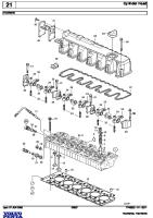
1.2
Travelling mechanism, driven 7
8
13
19 8
10 12 17
6 Y
11
X 15 14
9 16
6
18 5
2
3
4
16
Fig. 1 20 The groove width AD of the wheels on your trolley are stated in the trolley data sheet included in your test book.
Page 4
Data : 31.10.2008
1.2.1
AZP 200.3
see Figure 1 Page 4 Individual parts available Item Part no. Quantity
Designation
Dimensions
DIN
3 4 5 6 7 19 8
204 77626 73818 77379 71553 71554 5607
2 1 1 12 1 1 2
Ball bearing Bearing flange Bearing bolt Countersunk bolt Screw ---on plate Screw ---on plate Countersunk bolt
6212 Z
DIN 625
9
83541 85459 83540 83539 76416 76465 82378 76466
2 2 2 2 2 2 2 2
Guiding roll Guiding roll Guiding roll Guiding roll Guiding roll Guiding roll Guiding roll Guiding roll
ø125 mm ø122 mm ø115 mm ø112 mm ø100 mm ø105 mm ø102 mm ø110 mm
10 11 12 13 14 15 16
77497 77498 47034 83319 76425 72429 83146
2 2 2 2 2 6 1
Cylindrical roller bearing Nilos---ring Snap ring Countersunk bolt Track guide cover Flat head screw Stretch element
NUP 205 EC NUP 205 JV I 52 x 2 M10 x 50
DIN 5412
M6 x 16
DIN EN ISO 10642
17
83183
1
Holder
83188
1
Holder
85458
1
Holder
83191
1
Holder
Centre spacing Overall height Centre spacing Overall height Centre spacing Overall height Centre spacing Overall height
X=155 mm Y=57 mm X=155mm Y=61 mm X=175 mm Y=61 mm X=175mm Y=66 mm
83180
1
Protection element
18
Sets available Item Part no. Quantity 1
M10 x 30 6 x M10 8 x M10 M10 x 20
Designation
DIN 472
Scope of set (items) Item 2 ---3
77631 77633 77634 77635 77636 77637 77638 77639 77640 77641
1 1 1 1 1 1 1 1 1 1
Wheel machined with bearing Wheel machined with bearing Wheel machined with bearing Wheel machined with bearing Wheel machined with bearing Wheel machined with bearing Wheel machined with bearing Wheel machined with bearing Wheel machined with bearing Wheel machined with bearing
AD = 47mm AD = 52mm AD = 57mm AD = 62mm AD = 67mm AD = 72mm AD = 77mm AD = 82mm AD = 87mm AD = 92mm
77629
1
Wheel machined with bearing
without wheel flange
AN 120034.001_GB / E 360.GB
Page 5
SB x SH min [mm]
Guiding roll Crane [mm]
40 x 30
110
40 x 30
110
50 x 30 50 x 30
X
Y
155
57
155
61
100
155
57
100
155
61
175
66
175
61
175
66
175
61
175
66
50 x 40
Guiding roll Trolley[mm] 112
112
60 x 40
110
60 x 40
110
70 x 40
100
70 x 40
100
A 45 ( 45 x 55 )
125
175
61
A 45 ( 45 x 55 )
125
175
66
A 55 ( 55 x 65 )
115
175
61
A 55 ( 55 x 65 )
115
175
66
A 65 ( 65 x 75 )
105
175
61
A 65 ( 65 x 75 )
105
175
66
Page 6
112 102
Data : 31.10.2008
1.2.2
AZP 280.3
see Figure 1 Page 4 Individual parts available Item Part no. Quantity
Designation
Dimensions
DIN
3 4 5 6 7 19 8
206 86632 71909 8804 71908 71908 8606
2 1 1 12 1 1 2
Ball bearing Bearing flange Bearing bolt Countersunk bolt Screw ---on plate Screw ---on plate Countersunk bolt
6216 Z
DIN 625
9
86781 86782 86783 86784
2 2 2 2
Guiding roll Guiding roll Guiding roll Guiding roll
ø133 mm ø138 mm ø143 mm ø145 mm
10 11 12 13 14 15 16
72428 87127 236 8405 86792 86793 86785
2 2 2 2 2 6 1
Cylindrical roller bearing Nilos---ring Snap ring Screw Track guide cover Flat head screw Stretch element
NUP 206 E NUP 206 JV I 62 x 2 M12 x 60
DIN 472 DIN 6914
M6 x 16
DIN EN ISO 10642
17
86785
1
Holder
86786
1
Holder
86787
1
Holder
86788
1
Holder
86789
1
Holder
86790
1
Holder
87174
1
Holder
Centre spacing Overall height Centre spacing Overall height Centre spacing Overall height Centre spacing Overall height Centre spacing Overall height Centre spacing Overall height Centre spacing Overall height
X=188 mm Y=77 mm X=188 mm Y=68 mm X=198 mm Y=77 mm X=198 mm Y=68 mm X=208 mm Y=77 mm X=218 mm Y=77 mm X=208 mm Y=68 mm
86791 87497
1 1
Protection element Clamping
18 20
Sets available Item Part no. Quantity 1
M12 x 40 M12 x 25
Designation
DIN 5412
Scope of set (items) Item 2 ---3
86655 86657 86658 86659 86660 86661 86662 86663 86664 86665
1 1 1 1 1 1 1 1 1 1
Wheel machined with bearing Wheel machined with bearing Wheel machined with bearing Wheel machined with bearing Wheel machined with bearing Wheel machined with bearing Wheel machined with bearing Wheel machined with bearing Wheel machined with bearing Wheel machined with bearing
AD = 52mm AD = 57mm AD = 62mm AD = 67mm AD = 72mm AD = 77mm AD = 82mm AD = 87mm AD = 92mm AD = 97mm
86666
1
Wheel machined with bearing
without wheel flange
AN 120034.001_GB / E 360.GB
Page 7
SB x SH min [mm]
Guiding roll Crane [mm]
40 x 30
X
Y
143
188
68
40 x 40
143
188
77
50 x 30
143
198
68
50 x 40
143
198
77
60 x 30
143
208
68
60 x 40
133
198
77
208
77
208
77
218
77
60 x 40
Guiding roll Trolley[mm]
145
145
70 x 40
133
70 x 40
145
A 45 ( 45 x 55 )
138
188
77
A 55 ( 55 x 65 )
138
198
77
A 65 ( 65 x 75 )
138
208
77
A 75 ( 75 x 85 )
138
218
77
Page 8
145
Data : 31.10.2008
1.2.3
AZF 350.3
see Figure 1 Page 4 Individual parts available Item Part no. Quantity
Designation
Dimensions
DIN
3 4 5 6 7 19 8
300153 300156 300155 8804 300250 300250 8606
2 1 1 12 1 1 2
Ball bearing Bearing flange Bearing bolt Countersunk bolt Screw ---on plate Screw ---on plate Countersunk bolt
6219 --- 2Z
DIN 625
9
300279 300280 300281
2 2 2
Guiding roll Guiding roll Guiding roll
ø160 x 35.5 mm ø165 x 35.5 mm ø165 x 41 mm
10 11 12 13
2 4 2 2 2 2 8 1
Cylindrical roller bearing Nilos---ring Snap ring Screw Washer Track guide cover Flat head screw Stretch element
NUP 308 E NUP 308 JV I 90 x 3 M20 x 75 21
DIN 5412
14 15 16
300282 300283 7136 83389 83391 300256 10128 300251
M8 x 20
DIN EN ISO 10642
17
300265
1
Holder
300266
1
Holder
300267
1
Holder
300268
1
Holder
300269
1
Holder
300270
1
Holder
300271
1
Holder
300272
1
Holder
Centre spacing Overall height Centre spacing Overall height Centre spacing Overall height Centre spacing Overall height Centre spacing Overall height Centre spacing Overall height Centre spacing Overall height Centre spacing Overall height
X=215 mm Y=79 mm X=225 mm Y=79 mm X=235 mm Y=79 mm X=235 mm Y=92 mm X=245 mm Y=79 mm X=245 mm Y=92 mm X=255 mm Y=92 mm X=270 mm Y=92 mm
300254 300252
1 1
Protection element Clamping
18 20
Sets available Item Part no. Quantity 1
M12 x 40 M12 x 25
Designation
DIN 472 DIN EN 14399---4 DIN EN 14399---6
Scope of set (items) Item 2 ---3
302491 302492 302493 302494 302495 302496 302497 302498 302499
1 1 1 1 1 1 1 1 1
Wheel machined with bearing Wheel machined with bearing Wheel machined with bearing Wheel machined with bearing Wheel machined with bearing Wheel machined with bearing Wheel machined with bearing Wheel machined with bearing Wheel machined with bearing
AD = 57mm AD = 62mm AD = 67mm AD = 72mm AD = 77mm AD = 82mm AD = 87mm AD = 92mm AD = 97mm
302500
1
Wheel machined with bearing
without wheel flange
AN 120034.001_GB / E 360.GB
Page 9
SB x SH min [mm]
Guiding roll Crane [mm]
50 x 40
160
50 x 40 60 x 40
182 160
60 x 40 70 x 40
Guiding roll Trolley[mm]
182 160
70 x 40
182
X
Y
215
79
235
92
225
79
245
92
235
79
255
92
80 x 40
160
245
79
A 55 ( 55 x 65 )
165
225
79
A 65 ( 65 x 75 )
165
235
92
A 75 ( 75 x 85 )
165
245
92
A 100
165
270
92
Page 10
Data : 31.10.2008
2 7
6
5 4 3
Figure 2
1.2.4
AZF 400
Individual parts available Item
Part no. Quantity
Designation
Dimensions
2
49720 49547 49828 49548 49549
1 1 1 1 1
wheel machined wheel machined wheel machined wheel machined wheel machined
AD = 57mm AD = 62mm AD = 67mm AD = 72mm AD = 77mm
3 4 5 6 7
6607 3471 8817 46 16904
2 2 1 6 6
ball bearing bearing bolt thread protection plug filister–head screw Schnorr – spring ring
6218 ZZ mB. 10700 D=70 M16 x 30 VS 16
DIN
DIN 625 DIN 6912
Sets available Set 1
Part no. Quantity 44919 44920 44921 44922 44923
1 1 1 1 1
Designation wheel machined compl. wheel machined compl. wheel machined compl. wheel machined compl. wheel machined compl.
AN 120034.001_GB / E 360.GB
Scope of set (items) AD = 57mm AD = 62mm AD = 67mm AD = 72mm AD = 77mm
Item 2 – 7 Item 2 – 7 Item 2 – 7 Item 2 – 7 Item 2 – 7
Page 11
1.2.5
AZF 500
Individual parts available Item
Part no. Quantity
Designation
Dimensions
2
49644 49650 49651 49652 49653
1 1 1 1 1
wheel machined wheel machined wheel machined wheel machined wheel machined
AD = 57mm AD = 62mm AD = 67mm AD = 72mm AD = 77mm
3 4 5 6 7
19714 5661 8817 5681 16904
2 2 1 6 6
ball bearing bearing bolt thread protection plug filister–head screw Schnorr – spring ring
6220 ZZ mB. 10700 D=70 M16 x 35 VS 16
DIN
DIN 625 DIN 6912
Sets available Set
Part no. Quantity
1
Page 12
44924 44925 44926 44927 44928
1 1 1 1 1
Designation wheel machined compl. wheel machined compl. wheel machined compl. wheel machined compl. wheel machined compl.
Scope of set (items) AD = 57mm AD = 62mm AD = 67mm AD = 72mm AD = 77mm
Item 2 – 7 Item 2 – 7 Item 2 – 7 Item 2 – 7 Item 2 – 7
Data : 31.10.2008
1.3
Travelling mechanism, non–driven 11 8 10
15
Y
9
X 14 12
7
6
14
16
4
2
21
3
5
20
22
17 18 19 Fig. 3 The groove width AD of the wheels on your trolley are stated in the trolley data sheet included in your test book.
AN 120034.001_GB / E 360.GB
Page 13
1.3.1
AZP 200.3
see Fig. 3 Page 13 Individual parts available Item Part no. Quantity
Designation
Dimensions
DIN
3 4 5 6
204 5187 5663 231
2 1 1 1
Ball bearing Distance bush Bolt Snap ring
6212 Z
DIN 625
A60 x 2
DIN 471
7
83541 85459 83540 83539 76416 76465 82378 76466
2 2 2 2 2 2 2 2
Guiding roll Guiding roll Guiding roll Guiding roll Guiding roll Guiding roll Guiding roll Guiding roll
ø125 mm ø122 mm ø115 mm ø112 mm ø100 mm ø105 mm ø102 mm ø110 mm
8 9 10 11 12 13 14
77497 77498 47034 83319 76425 72429 83146
2 2 2 2 2 6 1
Cylindrical roller bearing Nilos---ring Snap ring Countersunk bolt Track guide cover Flat head screw Stretch element
NUP 205 EC NUP 205 JV I 52 x 2 M10 x 50
DIN 5412
M6 x 16
DIN EN ISO 10642
15
83183
1
Holder
83188
1
Holder
85458
1
Holder
83191
1
Holder
Centre spacing Overall height Centre spacing Overall height Centre spacing Overall height Centre spacing Overall height
X=155 mm Y=57 mm X=155mm Y=61 mm X=175 mm Y=61 mm X=175mm Y=66 mm
83180
1
Protection element
16
Sets available Item Part no. Quantity 1
Page 14
Designation
DIN 472
Scope of set (items) Item 2 ---3
77632 77642 77643 77644 77645 77645 77646 77647 77648 77649 77650
1 1 1 1 1 1 1 1 1 1 1
Wheel not machined with bearing Wheel not machined with bearing Wheel not machined with bearing Wheel not machined with bearing Wheel not machined with bearing Wheel not machined with bearing Wheel not machined with bearing Wheel not machined with bearing Wheel not machined with bearing Wheel not machined with bearing Wheel not machined with bearing
AD = 47mm AD = 52mm AD = 57mm AD = 62mm AD = 67mm AD = 67mm AD = 72mm AD = 77mm AD = 82mm AD = 87mm AD = 92mm
77630
1
Wheel not machined with bearing
without wheel flange
83722 83723 83913
2 2 2
Lift ---off prevention Wire rope hoist Lift ---off prevention Wire rope hoist Lift ---off prevention Wire rope hoist
SH = 30---40 SH = 60---70
Item 17 ---19 Item 17 ---19 Item 20 ---22
Data : 31.10.2008
SB x SH min [mm]
Guiding roll Crane [mm]
40 x 30
110
40 x 30
110
50 x 30 50 x 30
X
Y
155
57
155
61
100
155
57
100
155
61
175
66
175
61
175
66
175
61
175
66
50 x 40
Guiding roll Trolley[mm] 112
112
60 x 40
110
60 x 40
110
70 x 40
100
70 x 40
100
A 45 ( 45 x 55 )
125
175
61
A 45 ( 45 x 55 )
125
175
66
A 55 ( 55 x 65 )
115
175
61
A 55 ( 55 x 65 )
115
175
66
A 65 ( 65 x 75 )
105
175
61
A 65 ( 65 x 75 )
105
175
66
AN 120034.001_GB / E 360.GB
112 102
Page 15
1.3.2
AZP 280.3
see Fig. 3 Page 13 Individual parts available Item Part no. Quantity
Designation
Dimensions
DIN
3 4 5 6
206 5371 5664 233
2 1 1 1
Ball bearing Distance bush Bolt Snap ring
6216 Z
DIN 625
A80 x 2.5
DIN 471
7
86781 86782 86783 86784
2 2 2 2
Guiding roll Guiding roll Guiding roll Guiding roll
ø133 mm ø138 mm ø143 mm ø145 mm
8 9 10 11 12 13 14
72428 87127 236 8405 86792 72429 86793
2 2 2 2 2 6 1
Cylindrical roller bearing Nilos---ring Snap ring Screw Track guide cover Flat head screw Stretch element
NUP 206 E NUP 206 JV I 62 x 2 M12 x 60
DIN 472 DIN 6914
M6 x 16
DIN EN ISO 10642
15
86785
1
Holder
86786
1
Holder
86787
1
Holder
86788
1
Holder
86789
1
Holder
86790
1
Holder
87174
1
Holder
Centre spacing Overall height Centre spacing Overall height Centre spacing Overall height Centre spacing Overall height Centre spacing Overall height Centre spacing Overall height Centre spacing Overall height
X=188 mm Y=77 mm X=188 mm Y=68 mm X=198 mm Y=77 mm X=198 mm Y=68 mm X=208 mm Y=77 mm X=218 mm Y=77 mm X=208 mm Y=68 mm
86791
1
Protection element
16
Sets available Item Part no. Quantity 1
Page 16
Designation
DIN 5412
Scope of set (items) Item 2 ---3
86656 86667 86668 86669 86670 86671 86672 86673 86674 86675
1 1 1 1 1 1 1 1 1 1
Wheel not machined with bearing Wheel not machined with bearing Wheel not machined with bearing Wheel not machined with bearing Wheel not machined with bearing Wheel not machined with bearing Wheel not machined with bearing Wheel not machined with bearing Wheel not machined with bearing Wheel not machined with bearing
AD = 52mm AD = 57mm AD = 62mm AD = 67mm AD = 72mm AD = 77mm AD = 82mm AD = 87mm AD = 92mm AD = 97mm
86676
1
Wheel not machined with bearing
without wheel flange
87935 87936 87938
2 2 2
Lift ---off prevention Wire rope hoist Lift ---off prevention Wire rope hoist Lift---off prevention Wire rope hoist
SH = 30---40 SH = 50---70
Item 17 ---19 Item 17 ---19 Item 20 ---22
Data : 23.12.2008
SB x SH min [mm]
Guiding roll Crane [mm]
40 x 30
X
Y
143
188
68
40 x 40
143
188
77
50 x 30
143
198
68
50 x 40
143
198
77
60 x 30
143
208
68
60 x 40
133
198
77
208
77
208
77
218
77
60 x 40
Guiding roll Trolley[mm]
145
145
70 x 40
133
70 x 40
145
A 45 ( 45 x 55 )
138
188
77
A 55 ( 55 x 65 )
138
198
77
A 65 ( 65 x 75 )
138
208
77
A 75 ( 75 x 85 )
138
218
77
AN 120034.001_GB / E 360.GB
145
Page 17
1.3.3
AZF 350.3
see Fig. 3 Page 13 Individual parts available Item Part no. Quantity
Designation
Dimensions
DIN
3 4 5 6
300153 300249 300248 300152
2 1 1 1
Ball bearing Distance bush Bolt Snap ring
6219 --- 2Z
DIN 625
A95 x 3
DIN 471
7
300279 300280 300281
2 2 2
Guiding roll Guiding roll Guiding roll
ø160 x 35.5 mm ø165 x 35.5 mm ø165 x 41 mm
8 9 10 11
2 4 2 2 2 2 8 1
Cylindrical roller bearing Nilos---ring Snap ring Screw Washer Track guide cover Flat head screw Stretch element
NUP 308 E NUP 308 JV I 90 x 3 M20 x 75 21
DIN 5412
12 13 14
300282 300283 7136 83389 83391 300256 10128 300251
M8 x 20
DIN EN ISO 10642
15
300265
1
Holder
300266
1
Holder
300267
1
Holder
300268
1
Holder
300269
1
Holder
300270
1
Holder
300271
1
Holder
300272
1
Holder
Centre spacing Overall height Centre spacing Overall height Centre spacing Overall height Centre spacing Overall height Centre spacing Overall height Centre spacing Overall height Centre spacing Overall height Centre spacing Overall height
X=215 mm Y=79 mm X=225 mm Y=79 mm X=235 mm Y=79 mm X=235 mm Y=92 mm X=245 mm Y=79 mm X=245 mm Y=92 mm X=255 mm Y=92 mm X=270 mm Y=92 mm
300254
1
Protection element
16
Sets available Item Part no. Quantity 1
Designation
DIN 472 DIN EN 14399---4 DIN EN 14399---6
Scope of set (items) Item 2 ---3
302481 302482 302483 302484 302485 302486 302487 302488 302489
1 1 1 1 1 1 1 1 1
Wheel not machined with bearing Wheel not machined with bearing Wheel not machined with bearing Wheel not machined with bearing Wheel not machined with bearing Wheel not machined with bearing Wheel not machined with bearing Wheel not machined with bearing Wheel not machined with bearing
AD = 57mm AD = 62mm AD = 67mm AD = 72mm AD = 77mm AD = 82mm AD = 87mm AD = 92mm AD = 97mm
302490
1
Wheel not machined with bearing
without wheel flange
301706 301707
2 2
Lift ---off prevention Wire rope hoist Lift ---off prevention Wire rope hoist
SH = 30---50 SH = 60---70
Page 18
Item 17 ---19 Item 17 ---19
Data : 31.10.2008
SB x SH min [mm]
Guiding roll Crane [mm]
50 x 40
160
50 x 40 60 x 40
182 160
60 x 40 70 x 40
Guiding roll Trolley[mm]
182 160
70 x 40
182
X
Y
215
79
235
92
225
79
245
92
235
79
255
92
80 x 40
160
245
79
A 55 ( 55 x 65 )
165
225
79
A 65 ( 65 x 75 )
165
235
92
A 75 ( 75 x 85 )
165
245
92
A 100
165
270
92
AN 120034.001_GB / E 360.GB
Page 19
2
6
5 4 3 Figure 4
1.3.4
AZF 400
Individual parts available Item
Part no. Quantity
Designation
Dimensions
DIN
2
36412 36413 36414 36415 5713
1 1 1 1 1
wheel not machined wheel not machined wheel not machined wheel not machined wheel not machined
AD = 57mm AD = 62mm AD = 67mm AD = 72mm AD = 77mm
3 4 5 6
6607 6703 6701 1933
2 1 1 1
ball bearing distance bush bolt snap ring
6218 ZZ
DIN 625
90 x 3
DIN 471
Sets available Set
Part no. Quantity
1
Page 20
44929 44930 44931 44932 44933
1 1 1 1 1
Designation wheel not machined compl. wheel not machined compl. wheel not machined compl. wheel not machined compl. wheel not machined compl.
Scope of set (items) AD = 57mm AD = 62mm AD = 67mm AD = 72mm AD = 77mm
Item: 2 – 6 Item: 2 – 6 Item: 2 – 6 Item: 2 – 6 Item: 2 – 6
Data : 31.10.2008
1.3.5
AZF 500
Individual parts available Item
Part no. Quantity
Designation
Dimensions
DIN
2
37081 37082 37083 37084 37085
1 1 1 1 1
wheel not machined wheel not machined wheel not machined wheel not machined wheel not machined
AD = 57mm AD = 62mm AD = 67mm AD = 72mm AD = 77mm
3 4 5 6
19714 5662 5666 1283
2 1 1 1
ball bearing distance bush bolt snap ring
6220 ZZ
DIN 625
100 x 3
DIN 471
Sets available Set 1
Part no. Quantity 44934 44935 44936 44937 44938
1 1 1 1 1
Designation wheel not machined compl. wheel not machined compl. wheel not machined compl. wheel not machined compl. wheel not machined compl.
AN 120034.001_GB / E 360.GB
Scope of set (items) AD = 57mm AD = 62mm AD = 67mm AD = 72mm AD = 77mm
Item: 2 – 6 Item: 2 – 6 Item: 2 – 6 Item: 2 – 6 Item: 2 – 6
Page 21
1.4
Gear motors
1.4.1
AZP 200
Figure 5
The GE number of your trolley travel drive is given in the travelling crane data sheet included in your test book. Individual parts available Item
Part no. Quantity
Designation
Dimensions
DIN
SB 150 x 2.5
DIN 472
11 40 56 57 61 64 65
11132 12872 12873 12874 83118 86445 86815
1 4 1 1 1 1 1
gear box snap ring anchor disc fan with brake lining cover connecting block connecting block
7 pol. 4 pol.
80
12877 13200
4 4
screw screw
M6 x 270 M6 x 290
83 99
12878 8803
2 4
O-ring motor Verbus countersunk bolt
M12 x 30
Page 22
Motor 0.65 / 0.77 kW Motor 0.80 / 0.96 kW
Data : 31.10.2008
Sets available Set
Part no. Quantity
Designation
Scope of set (items):
3115 3116 12986 3117 12987 3122 12988 3123 12997
1 1 1 1 1 1 1 1 1
drive gear GE 2065 5/20 drive gear GE 2066 7.5/30 drive gear GE 2090 7.5/30 drive gear GE 2067 10/40 drive gear GE 2091 10/40 drive gear GE 2068 12.5/50 drive gear GE 2092 12.5/50 drive gear GE 2069 15/60 drive gear GE 2093 15/60 (380 – 415 V / 50 Hz // 440 --- 480 V / 60 HZ // Star)
12879 105581 11252 13388
1 1 1 1
O-rings gear connector housing ball bearing fan cowl compl.
Item: 38; 39 Item: 60; 61; 62; 63; 64; 65 Item: 71; 93 Item: 59; 89
12881
1
parts brake
Item: 73; 74; 76; 77; 79; 82 Motor 0.65 / 0.77 kW
13203
1
parts brake
Item: 73; 74; 76; 77; 79; 82 Motor 0.80 / 0.96 kW
1
stator compl.
Item: 52; 60; 61; 62; 81; 84 Motor 0.65 / 0.77 kW Motor 0.80 / 0.96 kW
13390
1
brake gearing shield compl.
Item: 55; 56; 74; 79; 82 Motor 0.65 / 0.77 kW
13391
1
brake gearing shield compl.
Item: 55; 56; 74; 79; 82 Motor 0.80 / 0.96 kW
12882 13230
AN 120034.001_GB / E 360.GB
6/24 9/36 9/36 12/48 12/48 15/60 15/60
m/min m/min m/min m/min m/min m/min m/min m/min m/min
Page 23
1.4.2
AZP 280
Figure 6
The Parts number of your trolley travel drive is given in the travelling crane data sheet included in your test book. Individual parts available Item
Part no. Quantity
11 40 56 57 61 64 65 80 83 99
Page 24
90023 90024 12872 12873 12874 83118 86445 86815 12877 13200 72481 12878 12685
1 1 4 1 1 1 1 1 4 4 4 2 4
Designation gear box gear box snap ring anchor disc fan with brake lining cover connecting block connecting block screw screw anchor bolt O-ring motor Verbus-countersunk bolt
Dimension
DIN
SB 150 x 2.5
3---stufig 2---stufig DIN 472
7 pol. 4 pol. M 6 x 270 M 6 x 290 M 6 x 340
Motor 0,65 / 0,78 kW Motor 0,80 / 0,96 kW Motor 1,10 / 1,30 kW
M 16 x 35
Data : 31.10.2008
Sets available Set
Part no. Quantity
Designation
Scope of set (items):
87054 87056 87057 87055 87058 87061 87059 87062 87060 87063
1 1 1 1 1 1 1 1 1 1
drive gear 5/20 drive gear 5/20 drive gear 7,5/30 drive gear 10/40 drive gear 10/40 drive gear 10/40 drive gear 12,5/50 drive gear 12,5/50 drive gear 15/60 drive gear 15/60 (380 – 415 V / 50 Hz // 440 --- 480 V / 60 HZ // Star)
13201 105581 72482 13388
1 1 1 1
O-rings gear connector housing ball bearing fan cowl compl.
Item: 38; 39 Item: 60; 61; 62; 63; 64; 65 Item: 71; 93 Item: 59; 89
12881
1
parts brake
Item: 73; 74; 76; 77; 79; 82 Motor 0,65 / 0,78 kW
13203
1
parts brake
Item: 73; 74; 76; 77; 79; 82 Motor 0,80 / 0,96 kW
72480
1
parts brake
Item: 73; 74; 76; 77; 79; 82 Motor 1,10 / 1,30 kW
1
stator compl.
Item: 52; 60; 61; 62; 81; 84 Motor 0,65 / 0,78 kW Motor 0,80 / 0,96 kW Motor 1,10 / 1,30 kW
13390
1
brake gearing shield compl.
Item: 55; 56; 74; 79; 82 Motor 0,65 / 0,78 kW
13391
1
brake gearing shield compl.
Item: 55; 56; 74; 79; 82 Motor 0,80 / 0,96 kW
72298
1
brake gearing shield compl.
Item: 55; 56; 74; 79; 82 Motor 1,10 / 1,30 kW
12882 13230 72478
AN 120034.001_GB / E 360.GB
6/24 6/24 9/36 12/48 12/48 12/48 15/60 15/60
m/min m/min m/min m/min m/min m/min m/min m/min m/min m/min
Page 25
1.4.3
AZF 350.3
Fig. 7
Drive gear AZF 350.3 The A ---number of your crane travel drive is given in the travelling crane data sheet included in your test book Page 26
Data : 31.10.2008
1.4.3.1
Gear
Induvidual parts available Item Part no. Quant.
Designation
Dimension
DIN
2 3 9 10 31 32
--- ----- --301111 --- --7351 6373
1 1 1 1 4 4
output shaft Snap ring SB 44 Snap ring A11 x 1 feather A 4 x 4 x 25 fillister---head screw M12 x 100 – 8.8 washer 13 – vz. (Items 31 and 32 must always be replaced together.)
36 43
--- ----- ---
1 1
screw plug packing ring
Sets available Set Part no.
Quant.
Designation
300654 300653 300652 300649 300647 300645 300644
1 1 1 1 1 1 1
Gear compl., i=154.09 Gear compl., i=106.8 Gear compl., i=78.39 Gear compl., i=63.19 Gear compl., i=53.12 Gear compl., i=39.67 Gear compl., i=32.37
v = 5/20 m/min v = 7,5/30 m/min v = 10/40 m/min v = 12,5/50 m/min v = 15/60 m/min v = 20/80 m/min v = 25/100 m/min
1
301343 301113
1 1
output shaft O---ring gear
AZF 350 compl.
2, 3 4, 5, 8
301678
1
Slipping clutch complete
(Set)
46
1.4.3.2
M12 x 1.5 A12 x 15
DIN 471 DIN 6885---1 DIN EN ISO 4762 DIN EN ISO 7092 DIN 908 DIN 7603
Content (Item)
Coupling / disc flywheel
Induvidual parts available Item Part no. Quant.
Designation
11 36
Gear coupling half Coupling element
Dimension
DIN
301346 48223
1 1
Sets available Set Part no.
Quant.
48077 48078 48079 48080
1 1 1 1
disc flywheel compl. disc flywheel compl. disc flywheel compl. disc flywheel compl.
ø140 x 20 ø160 x 20 ø160 x 28 ø160 x 50
6, 7, 12
301347
1
disc flywheel compl.
47
301348
1
disc flywheel compl.
ø160 x 20 for gear half ø160 x 28 for gear half
Designation
AN 120034.001_GB / E 360.GB
Content (Item)
Page 27
see Fig. 7 Page 26 1.4.3.3
Drive gear
Induvidual parts available Item Part no. Quant.
Designation
86526
1
elecrtonics for brake
6086
4
Verbus countersunk bolt
Sets available Set Part no.
Quant.
101134 101146 12654 105581 75810
35
1.4.3.4
Dimension
DIN (in motor connector housing)
M8 x 35
Designation
Content (Item)
1
Ball bearing, O---ring, Snap ring
26, 27, 40, 41, 43, 48
1 1 1 4
Fan rotor compl. Fan hood with screw motor connector housing Screw for motor mounting
23 --- 25 28, 29 30 34
size 1 compl.
Brake
Induvidual parts available Item Part no. Quant.
Designation
38
Dimension
DIN
48531
1
Packing ring
Sets available Set Part no.
Quant.
Designation
Content (Item)
101139
1
Brake rotorcompl.
18,19,20,21,23,38,39
Brake for voltage range 380---415 V / 50Hz / Star ; 220---240 V / 50Hz / Delta ; 208---230 V / 60Hz / Delta ; 360---400 V / 60Hz / Star 15
101655
1
Brake compl.
4.5 Nm, voltage for brake coil 103 VDC (for Motor 0.75, 0.9, 1.1 und 1.3 kW)
101140
1
Brake compl.
6 Nm, voltage for brake coil 103 VDC (for Motor 1.5 und 1.8 kW)
101141
1
Brake compl.
9 Nm, voltage for brake coil 103 VDC (for Motor 2.2 und 2.6 kW)
101142
1
Brake compl.
12 Nm, voltage for brake coil 103 VDC (for Motor 3.0 und 3.6 kW)
Brake for den voltage range 460---500 V / 50Hz / Star 15
101656
1
Brake compl.
4.5 Nm, voltage for brake coil 127 VDC (for Motor 0.75, 0.9, 1.1 und 1.3 kW)
101143
1
Brake compl.
6 Nm, voltage for brake coil 127 VDC (for Motor 1.5 und 1.8 kW)
101144
1
Brake compl.
9 Nm, voltage for brake coil 127 VDC (for Motor 2.2 und 2.6 kW)
101145
1
Brake compl.
12 Nm, voltage for brake coil 127 VDC (for Motor 3.0 und 3.6 kW)
Note: If a brake, item 15, is ordered, two flat sleeves, type AN 998, must also be ordered. Page 28
Data : 31.10.2008
see Fig. 7 Page 26 1.4.3.5
Drive gear complete with Brake
(includes connection flange, motor with connector housing, complete brake, fan hood) 380---415 V / 50Hz / Star 301071 1 301072 1 18387 1 18388 1
1.4.3.6
Motor compl. Motor compl. Motor compl. Motor compl.
0.75 kW 1.1 kW 1.5 kW 2.2 kW
Drive gear complete without Brake
(includes complete motor but without brake, fan rotor, fan hood or coupling parts) 380---415 V / 50Hz / Star 301073 1 301074 1 76550 1 76551 1
Motor Motor Motor Motor
0.75 kW 1.1 kW 1.5 kW 2.2 kW
(includes complete motor but without brake, fan rotor, fan hood or coupling parts) 380---415 V / 50Hz / Star 301032 1 301043 1
Drive gear compl. Drive gear compl.
0.75 kW 1.1 kW
5/20 m/min 5/20 m/min
301044 301048
1 1
Drive gear compl. Drive gear compl.
1.1 kW 1.5 kW
7.5/30 m/min 7.5/30 m/min
301049 301050 301052
1 1 1
Drive gear compl. Drive gear compl. Drive gear compl.
1.1 kW 1.5 kW 2.2 kW
10/40 m/min 10/40 m/min 10/40 m/min
301053 301054 301055
1 1 1
Drive gear compl. Drive gear compl. Drive gear compl.
1.1 kW 1.5 kW 2.2 kW
12.5/50 m/min 12.5/50 m/min 12.5/50 m/min
301056 301057 301058
1 1 1
Drive gear compl. Drive gear compl. Drive gear compl.
1.1 kW 1.5 kW 2.2 kW
15/60 m/min 15/60 m/min 15/60 m/min
301059 301060
1 1
Drive gear compl. Drive gear compl.
1.5 kW 2.2 kW
20/80 m/min 20/80 m/min
301061 301062
1 1
Drive gear compl. Drive gear compl.
1.5 kW 2.2 kW
25/100 m/min 25/100 m/min
AN 120034.001_GB / E 360.GB
Page 29
Figure 8
Page 30
Data : 31.10.2008
1.4.4
AZF 400
see Fig. 8 Page 30 1.4.4.1
Gear
Induvidual parts available Item Part no. Quant.
Designation
Dimension
output shaft Snap ring A50 x 2 Fillister---head screw M20x50 retaining washer VS20 (Items 8 and 9 must always be replaced together.) Oil level gauge
DIN
2 3 8 9
--- --1374 6352 16905
1 1 4 4
10
48109
2
Sets available Set Part no.
Quant.
48007 48008
1 1
Gear compl., i=168 Gear compl., i=114
v = 5/20 m/min v = 7,5/30 m/min
1
48071 48073
1 1
output shaft O---ring gear
AZF 400 compl.
2, 3 4, 5
16044
1
Slipping clutch complete
Designation
DIN 471 DIN 912---8.8
Content (Item)
If the entire gear unit is to be replaced, a blank nameplate (AN 79696) must also be ordered 1.4.4.2
Coupling / disc flywheel
Induvidual parts available Item Part no. Quant.
Designation
11 36
Gear coupling half Coupling element
18464 48223
1 1
Sets available Set Part no.
Quant.
48077 48078 48079 48080
1 1 1 1
1.4.4.3
Designation
DIN
Content (Item)
disc flywheel compl. disc flywheel compl. disc flywheel compl. disc flywheel compl.
ø140 x 20 ø160 x 20 ø160 x 28 ø160 x 50
6, 7, 12
Designation
Dimension
DIN
Drive gear
Induvidual parts available Item Part no. Quant. 86526
1
elecrtonics for brake
5923
4
Verbus countersunk bolt
Sets available Set Part no.
Quant.
101134 101146 12654 105581 75810
35
Dimension
(in motor connector housing) M10 x 35
Designation
Content (Item)
1
Ball bearing, O---ring, Snap ring
26, 27, 40, 41, 43, 48
1 1 1 4
Fan rotor compl. Fan hood with screw motor connector housing Screw for motor mounting
23 --- 25 28, 29 30 34
AN 120034.001_GB / E 360.GB
size 1 compl.
Page 31
1.4.4.4
Brake
Induvidual parts available Item Part no. Quant.
Designation
38
Dimension
DIN
48531
1
Packing ring
Sets available Set Part no.
Quant.
Designation
Content (Item)
101139
1
Brake rotorcompl.
18,19,20,21,23,38,39
Brake for voltage range 380---415 V / 50Hz / Star ; 220---240 V / 50Hz / Delta ; 208---230 V / 60Hz / Delta ; 360---400 V / 60Hz / Star 15
101655
1
Brake compl.
4.5 Nm, voltage for brake coil 103 VDC (for Motor 0.75, 0.9, 1.1 und 1.3 kW)
Brake for den voltage range 460---500 V / 50Hz / Star 15
101656
1
Brake compl.
4.5 Nm, voltage for brake coil 127 VDC (for Motor 0.75, 0.9, 1.1 und 1.3 kW)
Note: If a brake, item 15, is ordered, two flat sleeves, type AN 998, must also be ordered. 1.4.4.5
Drive gear complete with Brake
(includes connection flange, motor with connector housing, complete brake, fan hood) 380---415 V / 50Hz / Star 48014 1 48015 1
1.4.4.6
Motor compl. Motor compl.
0.75 kW 1.1 kW
Drive gear complete without Brake
(includes complete motor but without brake, fan rotor, fan hood or coupling parts) 380---415 V / 50Hz / Star 75820 1 75821 1
Motor Motor
0.75 kW 1.1 kW
(includes complete motor but without brake, fan rotor, fan hood or coupling parts) 380---415 V / 50Hz / Star 48031 1
Drive gear compl.
0.75 kW
5/20 m/min
48032 48040
Drive gear compl. Drive gear compl.
1.1 kW 1.5 kW
7.5/30 m/min 7.5/30 m/min
Page 32
1 1
Data : 31.10.2008
1.4.5
AZF 500
see Fig. 8 Page 30 1.4.5.1
Gear
Induvidual parts available Item Part no. Quant.
Designation
Dimension
output shaft Snap ring A60 x 2 Fillister---head screw Retaining washer VS20 (Items 8 and 9 must always be replaced together) Oil level gauge
DIN
2 3 8 9
--- --231 6352 16905
1 1 4 4
10
48109
2
Sets available Set Part no.
Quant.
48275 48276
1 1
Gear, i=219 Gear, i=145
v = 5/20 m/min v = 7,5/30 m/min
1
48309 48310
1 1
output shaft O---ring gear
AZF 500 compl.
2, 3 4, 5
75023
1
Slipping clutch complete (Set)
Designation
DIN 471
Content (Item)
If the entire gear unit is to be replaced, a blank nameplate (AN 79696) must also be ordered 1.4.5.2
Coupling / disc flywheel
Induvidual parts available Item Part no. Quant.
Designation
11 36
Gear coupling half Coupling element
18464 48223
1 1
Sets available Set Part no.
Quant.
48077 48078 48079 48080
1 1 1 1
1.4.5.3
Designation
DIN
Content (Item)
disc flywheel compl. disc flywheel compl. disc flywheel compl. disc flywheel compl.
ø140 x 20 ø160 x 20 ø160 x 28 ø160 x 50
6, 7, 12
Designation
Dimension
DIN
Drive gear
Induvidual parts available Item Part no. Quant. 86526
1
elecrtonics for brake
5923
4
Verbus countersunk bolt
Sets available Set Part no.
Quant.
101134 101146 12654 105581 75810
35
Dimension
(in motor connector housing) M10 x 35
Designation
Content (Item)
1
Ball bearing, O---ring, Snap ring
26, 27, 40, 41, 43, 48
1 1 1 4
Fan rotor compl. Fan hood with screw motor connector housing Screw for motor mounting
23 ---25 28, 29 30 34
AN 120034.001_GB / E 360.GB
size 1 compl.
Page 33
1.4.5.4
Brake
Induvidual parts available Item Part no. Quant.
Designation
38
Dimension
DIN
48531
1
Packing ring
Sets available Set Part no.
Quant.
Designation
Content (Item)
101139
1
Brake rotorcompl.
18 ---21, 23 ,38, 39
Brake for voltage range 380---415 V / 50Hz / Star ; 220---240 V / 50Hz / Delta ; 208---230 V / 60Hz / Delta ; 360---400 V / 60Hz / Star 15
101655
1
Brake compl.
4.5 Nm, voltage for brake coil 103 VDC (for Motor 1.1 und 1.3 kW)
101140
1
Brake compl.
6 Nm, voltage for brake coil 103 VDC (for Motor 1.5 und 1.8 kW)
101141
1
Brake compl.
9 Nm, voltage for brake coil 103 VDC (for Motor 2.2 und 2.6 kW)
Brake for den voltage range 460---500 V / 50Hz / Star 15
101656
1
Brake compl.
4.5 Nm, voltage for brake coil 127 VDC (for Motor 1.1 und 1.3 kW)
101143
1
Brake compl.
6 Nm, voltage for brake coil 127 VDC (for Motor 1.5 und 1.8 kW)
101144
1
Brake compl.
9 Nm, voltage for brake coil 127 VDC (for Motor 2.2 und 2.6 kW)
Note: If a brake, item 15, is ordered, two flat sleeves, type AN 998, must also be ordered.
1.4.5.5
Drive gear complete with Brake
(includes connection flange, motor with connector housing, complete brake, fan hood) 380---415 V / 50Hz / Star 48015 1 48016 1 48017 1
1.4.5.6
Motor compl. Motor compl. Motor compl.
1.1 kW 1.5 kW 2.2 kW
Drive gear complete without Brake
(includes complete motor but without brake, fan rotor, fan hood or coupling parts) 380---415 V / 50Hz / Star 75821 1 75822 1 75823 1
Page 34
Motor Motor Motor
1.1 kW 1.5 kW 2.2 kW
Data : 31.10.2008
The following article numbers include complete travel drives (motors with gear units). 380---415 V / 50Hz / Star 48282 1 48287 1
Drive gear compl. Drive gear compl.
1.1 kW 1.5 kW
5/20 m/min 5/20 m/min
48283 48288
Drive gear compl. Drive gear compl.
1.5 kW 2.2 kW
7.5/30 m/min 7.5/30 m/min
1 1
AN 120034.001_GB / E 360.GB
Page 35
1.5
Lifting gear drive
without additional unit for ventilation
with additional unit for ventilation
Figure 9 Please take the serial number of your complete hoist drive from the hoist nameplate. Page 36
Data : 31.10.2008
Lifting gear Individual parts available Item G17 G18 G19 G20 G21 G22 G24 G25 G27 G30 G33 G34 G411 G412
Part no. Quantity 13415 18541 18542 19522 18544 18545 18548 18551 18546 18553 11377 12893 6609 17483
1 1 1 1 1 1 1 2 4 2 1 2 4 4
Designation
Dimensions
DIN
ball bearing cylindrical roller bearing ball bearing cylindrical roller bearing ball bearing cylindrical roller bearing shaft gasket shaft gasket ball bearing gear rim oil level gauge screw plug fillister head screw washer
6310 2Z C3 HTF DIN 625 NJ 2309 DIN 5412 6315 2Z C3 HTF DIN 625 NJ 414 C3 DIN 5412 6316 2Z C3 HTF DIN 625 NJ 224E DIN 5412 120 x 150 x 15 SL 60 x 95 x 10 DIN 3760 VITON 6212 2Z DIN 625 ROTEX 38 / 45 GS 240 R1/2 R1 DIN 908 M 20 x 270 DIN EN ISO 4762 21 DIN 433
Designation
Dimensions
S 14255, 14256, 14257, 14258 S 14210, 14179, 14262, 14263
Lifting motor Individual parts available Item
Part no. Quantity
DIN
M1 M7
18801 23098 19509
2 2 2
clutch case end shield B end shield B
M41 M53 M60
11920 18802 11914
2 2 2
shaft gasket vent plug ball bearing compensating disc
M69
18594
8
filister–head screw
M69
13103
8
filister–head screw
M1247
18804
2
capacitor for additional unit
M80
15457
2
axial fan for additional unit for ventilation
S 14210, 14179, 14262, 14263
Designation
Dimensions
45 x 62 x 8
DIN 3760
99 x 89 x 0.6 BM 8x362x30 S 14255, 14256, 14257, 14258 BM 8x391x30 S 14210, 14179, 14262, 14263 S 14210, 14179, 14262, 14263
Hoist break Individual parts available Item B50 B51
Part no. Quantity 13105 11462
2 2
DIN
O–Ring connector
AN 120034.001_GB / E 360.GB
Page 37
see Figure 9 Page 36
Lifting gear drive Sets available Set
Part no. Quantity
Designation
Scope of set (items) S 14255 S 14210 S 14256 S 14179 S 14257 S 14262 S 14258 S 14263
25263
1
gear compl. (I = 232)
25264
1
gear compl. (I = 182)
25268
1
gear compl. (I = 148)
25270
1
gear compl. (I = 118)
Caution: the gearbox is supplied without a clutch. If required, the clutch must be ordered separately. 18568
2
clutch compl.
Item G29, G30, G39, G40
18587
2
S 14255, 14256, 14257, 14258
18592
2
motor with brake compl. (380–415V, 50Hz, 2.4/16kW/ 440–480V, 60Hz, 2.9/19.2kW) motor with brake compl. (380–415V, 50Hz, 3.0/20kW/ 440–480V, 60Hz, 3.6/24kW)
18063
2
stator compl. (Item M6, M43, 49)
S 14255, 14256, 14257, 14258 (380–415V, 50Hz, 2.4/16kW/ 440–480V, 60Hz, 2.9/19.2kW)
16234
2
stator compl. (Item M6, M43, 49)
S 14210, 14179, 14262, 14263 (380–415V, 50Hz, 3.0/20kW/ 440–480V, 60Hz, 3.6/24kW)
18549
2
rotor H6 compl. (Item. M7, M8, M9, M36, M37, M38, M39, M41, M62,M176)
S 14255, 14256, 14257, 14258
18550
2
rotor U6 compl. (Item M7, M8, M9, M36, M37, M38, M39, M41, M62,M176)
S 14210, 14179, 14262, 14263
106206
1
Motor connector housing incl. connector
Size 2 compl.
15451
2
magnet H6 + U6 (380–415V)
Item B6, B41, B51
13116 13106
2 2
brakerotor compl. fan cowl compl.
Item B4, B5, B19, B22, B50 Item M14, M74
13107
2
fan compl. (Item M15, M52, M96)
S 14255, 14256, 14257, 14258
18570 18810
2 1
bearing / packing motor small parts set gear
Item M37, M38, M41 Item G23, G35, G39, G40, G51
Quantities in parentheses ():
Page 38
S 14210, 14179, 14262, 14263
Item 49
apply to twin–motor version.
Data : 31.10.2008
1.6
Trolley frame
2,4,5
6 1
Figure 10
2,3,4,5 1.6.1
Reeving 2/1 D(B) and 4/2 D(B) --- (AZP 200)
Individual parts available Item
Part no. Quantity 4 3 2 3 6 16
Designation
Dimensions
buffer hinge pin hinge supporting bush axis holder Verbus countersunk bolt hexagonal nut
80 x 80
1 2 3 4 5 6
10431 39433 6815 30956 5607 516
1.6.2
Reeving 4/1 D(B), 8/2 D(B) and 4/2 Z(B) --- (AZP 280)
M 10 x 20 M10
DIN
DIN EN 24032
Individual parts available Item
Part no. Quantity 4 3 2 3 6 16
Designation
Dimensions
buffer hinge pin hinge supporting bush axis holder Verbus countersunk bolt hexagonal nut
100 x 100
1 2 3 4 5 6
10432 40537 4560 32823 5138 516
1.6.3
Reeving 6/1 D(B), 6/2 Z(B) --- (AZF 350.3)
DIN
M 16 x 25 M10
DIN EN 24032
DIN
Individual parts available Item
Part no. Quantity
Designation
Dimensions
1 2 3 4 5 6
10433 302402 302403 32823 5138 8804
buffer hinge pin hinge supporting bush axis holder Verbus countersunk bolt Verbus countersunk bolt
125 x 125
4 3 2 3 6 16
AN 120034.001_GB / E 360.GB
M 16 x 25 M 12 x 40 Page 39
1.6.4
Reeving 8/2 Z(B) --- (AZF 500)
see Fig. 10 Page 39 Individual parts available Item
Part no. Quantity
1 2 3 4 5 6
10433 47761 48998 32823 5138 8804
4 3 2 3 6 16
Designation
Dimensions
buffer hinge pin hinge supporting bush axis holder Verbus countersunk bolt Verbus countersunk bolt
125 x 125
DIN
M 16 x 25 M 12 x 40
_________________________________
2
3
5
6
4
7
1
8, 9, 10
Fig. 11
Page 40
Data : 31.10.2008
1.6.5
Reeving 4/1 DQA --- (AZF 400)
Individual parts available Item 1 2 3 4 5 6 7 8 9 10
Part no. Quantity 10432 25380 39543 25379 33459 8803 5138 5261 1531 1529
4 1 1 1 1 4 16 16 32 16
Designation
Dimensions
buffer hinge pin hinge supporting bush hinge supporting bush cover Verbus countersunk bolt Verbus countersunk bolt hexagonal-head screw washer hexagonal nut
100 x 100
AN 120034.001_GB / E 360.GB
M 12 x 30 M 16 x 25 M 20 x 70 21 M 20
DIN
DIN 6914 DIN 6916 DIN 6915
Page 41
1.7
Bottom block
1.7.1
Reeving 2/1 D(B) 5 8 7 10 1 2 3 11 4 9 6 22 23 18 17 15 16 19 12 20 13 21
14 Figure 12
Page 42
Data : 31.10.2008
Individual parts available Item 1 2 3 5 6 7 8 12 16 19 20 20 20 21 21 21 22 23
Part no. Quantity 6502 5896 5607 47675 47676 5945 5887 45179 6882 47670 7078 7078 1662 18085 7078 7078 47678 7351 13433 7779 7780 7787 19636 7782
1 2 4 1 1 2 2 2 1 1 1 1 1 2 2 2 2 2 1 1 1 1 1 1
Designation bolt cover Verbus countersunk bolt butt joint profile top butt joint profile lower header cab bracket axial–ball bearing hook crosshead hook lock safety device hook lock safety device hook lock safety device hook lock safety device hook lock safety device hook lock safety device distance sleeve filister–head screw nameplate capacity plate capacity plate capacity plate capacity plate capacity plate
Dimensions
DIN
M 10 x 20
425 51214 6 KO 60–6.8 KO 60–6.8 KO 60–10 KO 60–5 KO 60–6.8 KO 60–6.8
DIN 711 (normal hook GSN 6) (normal hook GSN 8) (normal hook GSN 10) (ramshorn hook GSN 6) (ramshorn hook GSN 8) (ramshorn hook GSN 10)
M 12 x 100
DIN EN ISO 4762
8 to 10 to 12,5 to 16 to 20 to
Sets available Set
Part no. Quantity
Designation
47937 47943 47944 47945 47946 47947 47674
bottom block compl. bottom block compl. bottom block compl. bottom block compl. bottom block compl. bottom block compl. hook suspension compl.
47689
hook suspension compl.
47690
hook suspension compl.
47691
hook suspension compl.
47692
hook suspension compl.
47693
hook suspension compl.
47673
hook with nut
47684
hook with nut
47685
hook with nut
47686
hook with nut
47687
hook with nut
47688
hook with nut
47767
rope pulley compl. with bearings
AN 120034.001_GB / E 360.GB
Scope of set (items) normal hook Gr. 6 normal hook Gr. 8 normal hook Gr. 10 ramshorn hook Gr. 6 ramshorn hook Gr. 8 ramshorn hook Gr. 10 normal hook Gr. 6 (Item 13, 15 – 20) normal hook Gr. 8 (Item 13, 15 – 20) normal hook Gr. 10 (Item 13, 15 – 20) ramshorn hook Gr. 6 (Item 14 – 19, 21) ramshorn hook Gr. 8 (Item 14 – 19, 21) ramshorn hook Gr. 10 (Item 14 – 19, 21) normal hook Gr. 6 (Item 13, 15, 17, 18, 20) normal hook Gr. 8 (Item 13, 15, 17, 18, 20) normal hook Gr. 10 (Item 13, 15, 17, 18, 20) ramshorn hook Gr. 6 (Item 14, 15, 17, 18, 21) ramshorn hook Gr. 8 (Item 14, 15, 17, 18, 21) ramshorn hook Gr. 10 (Item 14, 15, 17, 18, 21) (Item 9 – 11) Page 43
1.7.2
Reeving 4/1 D(B) and 4/2 Z(B)
6 8 9 10 12 11 2 1 3 19 18 4 5 16 17 20 7 13 21 22
15 14
Figure 13
Page 44
Data : 31.10.2008
Individual parts available Item 1 2 3 4 6 7 8 9 13 17 20 21 21 21 22 22 22
Part no. Quantity 5869 5896 5607 7615 47675 47676 5945 5887 41670 7503 41671 7391 15873 13196 1662 7391 15873 13433 19636 7782 7783 19637 7786
1 2 4 2 2 2 4 4 2 1 1 1 1 1 2 2 2 1 1 1 1 1 1
Designation bolt cover Verbus countersunk bolt vent plug butt joint profile top butt joint profile lower header cab bracket axial–ball bearing hook crosshead hook lock safety device hook lock safety device hook lock safety device hook lock safety device hook lock safety device hook lock safety device nameplate capacity plate capacity plate capacity plate capacity plate capacity plate
Dimensions
DIN
M 10 x 20
425 51222 16 KO 60–12 KO 60–16 KO 60–20.25 KO 60–10 KO 60–12 KO 60–16
DIN 711 (normal hook GSN 12) (normal hook GSN 16) (normal hook GSN 20) (ramshorn hook GSN 12) (ramshorn hook GSN 16) (ramshorn hook GSN 20)
16 to 20 to 25 to 32 to 40 to
Sets available Set
Part no. Quantity
Designation
47778 47779 47780 47781 47782 47783 47697
bottom block compl. bottom block compl. bottom block compl. bottom block compl. bottom block compl. bottom block compl. hook suspension compl.
47698
hook suspension compl.
47699
hook suspension compl.
47769
hook suspension compl.
47770
hook suspension compl.
47771
hook suspension compl.
40966
hook with nut
33017
hook with nut
40968
hook with nut
40969
hook with nut
32807
hook with nut
40971
hook with nut
47767
rope pulley compl. with bearings
AN 120034.001_GB / E 360.GB
Scope of set (items) normal hook Gr. 12 normal hook Gr. 16 normal hook Gr. 20 ramshorn hook Gr. 12 ramshorn hook Gr. 16 ramshorn hook Gr. 20 normal hook Gr. 12 (Item 14, 16 – 21) normal hook Gr. 16 (Item 14, 16 – 21) normal hook Gr. 20 (Item 14, 16 – 21) ramshorn hook Gr. 12 (Item 15 – 20, 22) ramshorn hook Gr. 16 (Item 15 – 20, 22) ramshorn hook Gr. 20 (Item 15 – 20, 22) normal hook Gr. 12 (Item 14, 16, 18, 19, 21) normal hook Gr. 16 (Item 14, 16, 18, 19, 21) normal hook Gr. 20 (Item 14, 16, 18, 19, 21) ramshorn hook Gr. 12 (Item 15, 16, 18, 19, 22) ramshorn hook Gr. 16 (Item 15, 16, 18, 19, 22) ramshorn hook Gr. 20 (Item 15, 16, 18, 19, 22) (Item 10 – 12) Page 45
1.7.3
Reeving 4/2 D(B)
5 7 8 9 10 12 11 1 2 3 19 18 4 16 17 20 13 6 21 14
22
15
Figure 14
Page 46
Data : 31.10.2008
Individual parts available Item 1 2 3 4 5 6 7 8 9 13 17 20 21 21 21 22 22 22
Part no. Quantity 32426 8604 5607 7615 32490 32491 7457 7483 7484 32425 7377 32422 7078 7078 1662 18085 7078 7078 13433 7779 7780 7787 19636 7782
1 2 4 2 2 2 4 4 4 2 1 1 1 1 1 2 2 2 1 1 1 1 1 1
Designation bolt cover Verbus countersunk bolt vent plug butt joint profile top butt joint profile lower header outsidecab insidecab bracket axial–ball bearing hook crosshead hook lock safety device hook lock safety device hook lock safety device hook lock safety device hook lock safety device hook lock safety device nameplate capacity plate capacity plate capacity plate capacity plate capacity plate
Dimensions
DIN
M 10 x 20
51216 16 KO 60–6.8 KO 60–6.8 KO 60–10 KO 60–5 KO 60–6.8 KO 60–6.8
DIN 711 (normal hook GSN 6) (normal hook GSN 8) (normal hook GSN 10) (ramshorn hook GSN 6) (ramshorn hook GSN 8) (ramshorn hook GSN 10)
8 to 10 to 12,5 to 16 to 20 to
Sets available Set
Part no. Quantity
Designation
41394 41395 41396 41397 41398 41399 41378
bottom block compl. bottom block compl. bottom block compl. bottom block compl. bottom block compl. bottom block compl. hook suspension compl.
31875
hook suspension compl.
31876
hook suspension compl.
41381
hook suspension compl.
31879
hook suspension compl.
31880
hook suspension compl.
41372
hook with nut
31807
hook with nut
31808
hook with nut
41375
hook with nut
31809
hook with nut
31810
hook with nut
41282
rope pulley compl. with bearings
AN 120034.001_GB / E 360.GB
Scope of set (items) normal hook Gr. 6 normal hook Gr. 8 normal hook Gr. 10 ramshorn hook Gr. 6 ramshorn hook Gr. 8 ramshorn hook Gr. 10 normal hook Gr. 6 (Item 14, 16 – 21) normal hook Gr. 8 (Item 14, 16 – 21) normal hook Gr. 10 (Item 14, 16 – 21) ramshorn hook Gr. 6 (Item 15 – 20, 22) ramshorn hook Gr. 8 (Item 15 – 20, 22) ramshorn hook Gr. 10 (Item 15 – 20, 22) normal hook Gr. 6 (Item 14, 16, 18, 19, 21) normal hook Gr. 8 (Item 14, 16, 18, 19, 21) normal hook Gr. 10 (Item 14, 16, 18, 19, 21) ramshorn hook Gr. 6 (Item 15, 16, 18, 19, 22) ramshorn hook Gr. 8 (Item 15, 16, 18, 19, 22) ramshorn hook Gr. 10 (Item 15, 16, 18, 19, 22) (Item 10 – 12) Page 47
1.7.4
Reeving 6/1 D(B) and 6/2 Z(B)
Figure 15
Page 48
Data : 31.10.2008
Individual parts available Item 1 2 3 4 6 7 8 9 13 14 18 21 22 22 22 23 23 23
Part no. Quantity 6503 5896 5607 7615 47675 47676 5945 5887 45189 46439 44688 17486 13196 13196 18855 15873 13196 18856 13433 7783 19637 7786 7756 19707 19638
1 4 8 2 3 3 6 6 2 2 1 1 1 1 1 2 2 2 1 1 1 1 1 1 1
Designation bolt cover Verbus countersunk bolt vent plug butt joint profile top butt joint profile tower header cab bracket distance holder hook crosshead axial–ball bearing hook lock safety device hook lock safety device hook lock safety device hook lock safety device hook lock safety device hook lock safety device nameplate capacity plate capacity plate capacity plate capacity plate capacity plate capacity plate
Dimensions
DIN
M 10 x 20
425 20 51224 KO 60–20.25 KO 60–20.25 KO 60–32.1 KO 60–16 KO 60–20.25 KO 60–32.2
DIN 711 (normal hook GSN 20) (normal hook GSN 25) (normal hook GSN 32) (ramshorn hook GSN20) (ramshorn hook GSN25) (ramshorn hook GSN32)
25 to 32 to 40 to 50 to 60 to 63 to
Sets available Set
Part no. Quantity
Designation
47836 47839 47841 47837 47842 47843 47808
bottom block compl. bottom block compl. bottom block compl. bottom block compl. bottom block compl. bottom block compl. hook suspension compl.
48825
hook suspension compl.
48826
hook suspension compl.
47815
hook suspension compl.
48827
hook suspension compl.
48828
hook suspension compl.
47794
hook with nut
48821
hook with nut
48822
hook with nut
47798
hook with nut
48823
hook with nut
48824
hook with nut
47767
rope pulley compl. with bearings
AN 120034.001_GB / E 360.GB
Scope of set (items) normal hook Gr. 20 normal hook Gr. 25 normal hook Gr. 32 ramshorn hook Gr. 20 ramshorn hook Gr. 25 ramshorn hook Gr. 32 normal hook Gr. 20 (Item 15, 17 – 22) normal hook Gr. 25 (Item 15, 17 – 22) normal hook Gr. 32 (Item 15, 17 – 22) ramshorn hook Gr. 20 (Item 16 – 21, 23) ramshorn hook Gr. 25 (Item 16 – 21, 23) ramshorn hook Gr. 32 (Item 16 – 21, 23) normal hook Gr. 20 (Item 15, 17, 19, 20, 22) normal hook Gr. 25 (Item 15, 17, 19, 20, 22) normal hook Gr. 32 (Item 15, 17, 19, 20, 22) ramshorn hook Gr. 20 (Item 16, 17, 19, 20, 23) ramshorn hook Gr. 25 (Item 16, 17, 19, 20, 23) ramshorn hook Gr. 32 (Item 16, 17, 19, 20, 23) (Item 10 – 12) Page 49
1.7.5
Reeving 8/2 D(B)
6 9 10 8 11 13 12 1 15 3 2 4 5 7 21 20 18 22 3 2 19 14 23 16
24 17
Figure 16
Page 50
Data : 31.10.2008
Individual parts available Item 1 2 3 4 6 7 8 9 10 14 15 19 22 23 23 23 24 24 24
Part no. Quantity 32788 8604 5607 7615 32490 32491 7457 7483 7484 32786 32784 32793 7503 7391 15873 13196 1662 7391 15873 13433 19636 7782 7783 19637 7786
1 4 8 4 4 4 8 6 2 2 1 1 1 1 1 1 2 2 2 1 1 1 1 1 1
Designation bolt cover Verbus countersunk bolt vent plug butt joint profile top butt joint profile tower header cab outside cab inside bracket distance holder hook crosshead axial–ball bearing hook lock safety device hook lock safety device hook lock safety device hook lock safety device hook lock safety device hook lock safety device nameplate capacity plate capacity plate capacity plate capacity plate capacity plate
Dimensions
DIN
M 10 x 20
51222 KO 60–12 KO 60–16 KO 60–20.25 KO 60–10 KO 60–12 KO 60–16
DIN 711 (normal hook GSN 12) (normal hook GSN 16) (normal hook GSN 20) (rams horn hook GSN 12) (rams horn hook GSN 16) (rams horn hook GSN 20)
16 to 20 to 25 to 32 to 40 to
Sets available Set
Part no. Quantity
Designation
41915 41916 41917 41918 41919 41920 40974
bottom block compl. bottom block compl. bottom block compl. bottom block compl. bottom block compl. bottom block compl. hook suspension compl.
33034
hook suspension compl.
40977
hook suspension compl.
40975
hook suspension compl.
32809
hook suspension compl.
40979
hook suspension compl.
40966
hook with nut
33017
hook with nut
40968
hook with nut
40969
hook with nut
32807
hook with nut
40971
hook with nut
41282
rope pulley compl. with bearings
AN 120034.001_GB / E 360.GB
Scope of set (items) normal hook Gr. 12 normal hook Gr. 16 normal hook Gr. 20 rams horn hook Gr. 12 rams horn hook Gr. 16 rams horn hook Gr. 20 normal hook Gr. 12 (Item 16, 18 – 23) normal hook Gr. 16 (Item 16, 18 – 23) normal hook Gr. 20 (Item 16, 18 – 23) rams horn hook Gr. 12 (Item 17 – 22, 24) rams horn hook Gr. 16 (Item 17 – 22, 24) rams horn hook Gr. 20 (Item 17 – 22, 24) normal hook Gr. 12 (Item 16, 18, 20, 21, 23) normal hook Gr. 16 (Item 16, 18, 20, 21, 23) normal hook Gr. 20 (Item 16, 18, 20, 21, 23) rams horn hook Gr. 12 (Item 17, 18, 20, 21, 24) rams horn hook Gr. 16 (Item 17, 18, 20, 21, 24) rams horn hook Gr. 20 (Item 17, 18, 20, 21, 24) (Item 11 – 13) Page 51
1.7.6
Reeving 8/2 Z(B)
Figure 17
Page 52
Data : 31.10.2008
Individual parts available Item 1 2 3 4 6 7 8 9 13 14 18 21 22 22 22 23 23 23
Part no. Quantity 6503 5896 5607 7615 47675 47676 5945 5887 45189 46448 46441 6608 13196 18855 18857 13196 18856 18855 13433 7783 19637 7786 7756 19707 19638 19639
1 4 8 4 4 4 8 8 2 1 1 1 1 1 1 2 2 2 1 1 1 1 1 1 1 1
Designation bolt cover Verbus countersunk bolt vent plug butt joint profile top butt joint profile tower header cab bracket distance holder hook crosshead axial–ball bearing hook lock safety device hook lock safety device hook lock safety device hook lock safety device hook lock safety device hook lock safety device nameplate capacity plate capacity plate capacity plate capacity plate capacity plate capacity plate capacity plate
Dimensions
DIN
M 10 x 20
425 25 51226 KO 60–20.25 KO 60–32.1 KO 60–40.50 KO 60–20.25 KO 60–32.2 KO 60–32.1
DIN 711 (normal hook GSN 25) (normal hook GSN 32) (normal hook GSN 40) (rams horn hook GSN 25) (rams horn hook GSN 32) (rams horn hook GSN 40)
25 to 32 to 40 to 50 to 60 to 63 to 80 to
Sets available Set
Part no. Quantity
Designation
47844 47846 47847 47845 47848 47849 47809
bottom block compl. bottom block compl. bottom block compl. bottom block compl. bottom block compl. bottom block compl. hook suspension compl.
47813
hook suspension compl.
47814
hook suspension compl.
47816
hook suspension compl.
47817
hook suspension compl.
47818
hook suspension compl.
47795
hook with nut
47796
hook with nut
47797
hook with nut
47799
hook with nut
47803
hook with nut
47804
hook with nut
47767
rope pulley compl. with bearings
AN 120034.001_GB / E 360.GB
Scope of set (items) normal hook Gr. 25 normal hook Gr. 32 normal hook Gr. 40 rams horn hook Gr. 25 rams horn hook Gr. 32 rams horn hook Gr. 40 normal hook Gr. 25 (Item 15, 17 – 22) normal hook Gr. 32 (Item 15, 17 – 22) normal hook Gr. 40 (Item 15, 17 – 22) rams horn hook Gr. 25 (Item 16 – 21, 23) rams horn hook Gr. 32 (Item 16 – 21, 23) rams horn hook Gr. 40 (Item 16 – 21, 23) normal hook Gr. 25 (Item 15, 17, 19, 20, 22) normal hook Gr. 32 (Item 15, 17, 19, 20, 22) normal hook Gr. 40 (Item 15, 17, 19, 20, 22) rams horn hook Gr. 25 (Item 16, 17, 19, 20, 23) rams horn hook Gr. 32 (Item 16, 17, 19, 20, 23) rams horn hook Gr. 40 (Item 16, 17, 19, 20, 23) (Item 10 – 12) Page 53
1.8
Upper block
1.8.1
Reeving 8/2 D(B)
1 2 4 5 8 7 6 3
Figure 18 Individual parts available Item
Part no. Quantity
1
40343
2
Designation
Dimensions
deflection roller crosshead
14.5
DIN
Sets available Set
Part no. Quantity 40344 41282 22844
Page 54
2 2 2
Designation deflection roller crosshead compl. rope pulley compl. with bearing bolt compl.
Scope of set (items) 14.5
(Item 1 – 8) (Item 2 – 4) (Item 5 – 8)
Data : 31.10.2008
1.8.2
Reeving 4/2 Z(B)
1 4 3 7 6 5 2 Figure 19
Individual parts available Item 1
Part no. Quantity 17523
1
Designation
Dimensions
deflection roller crosshead
20
DIN
Sets available Set
Part no. Quantity 47884 47767 16965
1 1 1
Designation deflection roller crosshead compl. rope pulley compl. with bearing bolt compl.
AN 120034.001_GB / E 360.GB
Scope of set (items) 20
(Item 1 – 7) (Item 2 – 4) (Item 5 – 7)
Page 55
1.8.3
Reeving 4/2 Z(B) with measuring axis
1 4 3
7 6 8 9 10 2
Figure 20
Individual parts available Item
Part no. Quantity
1
17523
1
Designation
Dimensions
deflection roller crosshead
20
DIN
Sets available Set
Part no. Quantity
Page 56
48843
1
47767 16966
1 1
Designation deflection roller crosshead with measuring axis rope pulley compl. with bearing bolt with measuring axis compl.
Scope of set (items) compl.
(Item 1 – 4, 6 – 10) (Item 2 – 4) (Item 6 – 10)
Data : 31.10.2008
1.8.4
Reeving 6/1 D(B) and 6/2 Z(B)
1 4 3 7 6 5 2 Figure 21
Individual parts available Item 1
Part no. Quantity 17523
2
Designation
Dimensions
deflection roller crosshead
20
DIN
Sets available Set
Part no. Quantity 47884 47767 16965
2 2 2
Designation deflection roller crosshead compl. rope pulley compl. with bearing bolt compl.
AN 120034.001_GB / E 360.GB
Scope of set (items) 20
(Item 1 – 7) (Item 2 – 4) (Item 5 – 7)
Page 57
1.8.5
Reeving 6/2 Z(B) with measuring axis
1 4
1
5
4
7
3
6 3
6 7 8
2
9 10 2 Figure 22
Individual parts available Item
Part no. Quantity
1
17523
2
Designation
Dimensions
deflection roller crosshead
20
DIN
Sets available Set
Part no. Quantity
Page 58
47884 48843
1 1
47767 16965 16966
2 1 1
Designation deflection roller crosshead cpmpl. deflection roller crosshead with measuring axis rope pulley compl. with bearing bolt compl. measuring axis compl.
Scope of set (items) 20
(Item 1 – 7)
compl.
(Item 1 – 4, 6 – 10) (Item 2 – 4) (Item 5 – 7) (Item 6 – 10)
Data : 31.10.2008
1.8.6
Reeving 8/2 Z(B)
Figure 23
Individual parts available Item 1
Part no. Quantity 17523
3
Designation
Dimensions
deflection roller crosshead
20
DIN
Sets available Set
Part no. Quantity 47884 47767 16965
3 3 3
Designation deflection roller crosshead compl. rope pulley compl. with bearing bolt compl.
AN 120034.001_GB / E 360.GB
Scope of set (items) 20
(Item 1 – 7) (Item 2 – 4) (Item 5 – 7)
Page 59
1.8.7
Reeving 8/2 Z(B) with measuring axis
Figure 24
Individual parts available Item
Part no. Quantity
1
17523
3
Designation
Dimensions
deflection roller crosshead
20
DIN
Sets available Set
Part no. Quantity
Page 60
47884 48843
2 1
47767 16965 16966
3 2 1
Designation deflection roller crosshead compl. deflection roller crosshead with measuring axis rope pulley compl. with bearing bolt compl. measuring axis compl.
Scope of set (items) 20
(Item 1 – 7)
compl.
(Item 1 – 4, 6 – 10) (Item 2 – 4) (Item 5 – 7) (Item 6 – 10)
Data : 31.10.2008
1.9
Rope guide , rope 9
10
1
2
X
6
7
X
3 4 5 8
Figure 25
for all types of reeving except 4/2 D(B) and 8/2 D(B) Sets available Set
Part no. Quantity 47885 45811 16960
1 1 1
Designation rope guide clamp clip compl. carrier compl.
Scope of set (items) 405 compl.
(Item 1 – 10) (Item 2 – 5) (Item 9 and 10)
only for 4/2 D(B) and 8/2 D(B) reeving Sets available Set
Part no. Quantity 28848 28847 45811 16960
1 1 2 2
Designation rope guide (right–handed) rope guide (left–handed) clamp clip compl. carrier compl.
Scope of set (items) 403 compl. 403 compl.
(Item 1 – 10) (Item 1 – 10) (Item 2 – 5) (Item 9 and 10)
Rope, without figure Set
Part no. Quantity
Designation
Scope of set (items)
85438 83938 90207
1 1 1
wire rope 20mm x 41.05m wire rope 20mm x 69.05m wire rope 20mm x 99.05m
reeving 2/1 D(B) reeving 2/1 D(B) reeving 2/1 D(B)
HW=16m HW=30m HW=45m
18811 18812
1 1
wire rope 20.5mm x 41.05m wire rope 20.5mm x 69.05m
reeving 2/1 D(B) reeving 2/1 D(B)
HW=16m HW=30m
AN 120034.001_GB / E 360.GB
Page 61
Set
Part no. Quantity
Designation
Scope of set (items)
85439 85440 85441 85442
1 1 1 1
wire rope 20mm x 43.70m wire rope 20mm x 71.70m wire rope 20mm x 101.70m wire rope 20mm x 121.70m
reeving 4/1 D(B) reeving 4/1 D(B) reeving 4/1 D(B) reeving 4/1 D(B)
HW=8m HW=15m HW=22.5m HW=27.5m
18814 18815 18816
1 1 1
wire rope 20.5mm x 43.70m wire rope 20.5mm x 71.70m wire rope 20.5mm x 101.70m
reeving 4/1 D(B) reeving 4/1 D(B) reeving 4/1 D(B)
HW=8m HW=15m HW=22.5m
19324 19325 19326
1 1 1
wire rope 14mm x 45.60m wire rope 14mm x 84.30m wire rope 14mm x 125.80m
reeving 4/2 D(B) reeving 4/2 D(B) reeving 4/2 D(B)
HW=7.3m HW=17m HW=27.3m
85443 85444 85445
1 1 1
wire rope 20mm x 47.00m wire rope 20mm x 75.00m wire rope 20mm x 105.00m
reeving 6/1 D(B) reeving 6/1 D(B) reeving 6/1 D(B)
HW=5m HW=10m HW=15m
18859 18860 18861
1 1 1
wire rope 20.5mm x 47.00m wire rope 20.5mm x 75.00m wire rope 20.5mm x 105.00m
reeving 6/1 D(B) reeving 6/1 D(B) reeving 6/1 D(B)
HW=5m HW=10m HW=15m
19305 19306 19307
1 1 1
wire rope 14mm x 55.30m wire rope 14mm x 94.50m wire rope 14mm x 136.10m
reeving 8/2 D(B) reeving 8/2 D(B) reeving 8/2 D(B)
HW=4.3m HW=9.2m HW=14.4m
72487 72488 72489
1 1 1
wire rope 20mm x 82.90m wire rope 20mm x 138.90m wire rope 20mm x 198.90m
reeving 4/2 Z(B) reeving 4/2 Z(B) reeving 4/2 Z(B)
HW=16m HW=30m HW=45m
18954 18955 18956
1 1 1
wire rope 20.5mm x 82.90m wire rope 20.5mm x 138.90m wire rope 20.5mm x 198.90m
reeving 4/2 Z(B) reeving 4/2 Z(B) reeving 4/2 Z(B)
HW=16m HW=30m HW=45m
72490 72491 72492
1 1 1
wire rope 20mm x 85.70m wire rope 20mm x 141.70m wire rope 20mm x 201.70m
reeving 6/2 Z(B) reeving 6/2 Z(B) reeving 6/2 Z(B)
HW=10.6m HW=20m HW=30m
18999 19132 19133
1 1 1
wire rope 20.5mm x 85.70m wire rope 20.5mm x 141.70m wire rope 20.5mm x 201.70m
reeving 6/2 Z(B) reeving 6/2 Z(B) reeving 6/2 Z(B)
HW=10.6m HW=20m HW=30m
72493 72494 72495
1 1 1
wire rope 20mm x 88.50m wire rope 20mm x 144.50m wire rope 20mm x 204.50m
reeving 8/2 Z(B) reeving 8/2 Z(B) reeving 8/2 Z(B)
HW=8m HW=15m HW=22.5m
18898 18899 18919
1 1 1
wire rope 20.5mm x 88.50m wire rope 20.5mm x 144.50m wire rope 20.5mm x 204.50m
reeving 8/2 Z(B) reeving 8/2 Z(B) reeving 8/2 Z(B)
HW=8m HW=15m HW=22.5m
You can take the rope diameter and the rope length of your ABUS electric wire rope in the wire certificate of the crane book.
Page 62
Data : 31.10.2008
1.10
Rope drum 1
2
3
5
Figure 26
4
6
7
8
for all types of reeving except 4/2 D(B) and 8/2 D(B) Individual parts available Item 2 3
Part no. Quantity 6616 6628
3 3
Designation
Dimensions
DIN
terminal clamp filister–head screw
20 mm M 20 x 40
DIN 6912
Sets available Set
Part no. Quantity 47880 47881 47882 16967
1 1 1 1
Designation rope drum compl. rope drum compl. rope drum compl. self–aligning roller bearing compl.
Scope of set (items) length= 850 mm length=1330 mm length=1830 mm
(Item 1 – 8) (Item 1 – 8) (Item 1 – 8) (Item 4 – 8)
only for 4/2 D(B) and 8/2 D(B) reeving Individual parts available Item 2 3
Part no. Quantity 9960 5681
3 3
Designation
Dimensions
DIN
terminal clamp filister–head screw
14–16 mm M 16 x 35
DIN 6912
Sets available Set
Part no. Quantity 44588 44589 44590 16967
1 1 1 1
Designation rope drum compl. rope drum compl. rope drum compl. self–aligning roller bearing compl.
AN 120034.001_GB / E 360.GB
Scope of set (items) length= 850 mm length=1330 mm length=1830 mm
(Item 1 – 8) (Item 1 – 8) (Item 1 – 8) (Item 4 – 8) Page 63
1.11
Deflection roller crosshead
for all types of reeving except 4/2 D(B) and 8/2 D(B) 1 4 3 7 6 5
2
Figure 27
Individual parts available Item
Part no. Quantity
1
17523
1
Designation
Dimensions
deflection roller crosshead
20
DIN
Sets available Set
Part no. Quantity 47884 47767 16965
Page 64
1 1 1
Designation deflection roller crosshead compl. rope pulley compl. with bearing bolt compl.
Scope of set (items) (Item 1 – 7) (Item 2 – 4) (Item 5 – 7)
Data : 31.10.2008
Load measuring system for deflection roller crosshead (opt. at reeving 4/2 --- 6/2 --- 8/2 Z(B)) 1
4 3 7 6 8 9 10 2 with Option load measuring system
Figure 28
Individual parts available Item 1
Part no. Quantity 17523
1
Designation
Dimensions
deflection roller crosshead
20
DIN
Sets available Set
Part no. Quantity 48843
1
47767 16966
1 1
Designation deflection roller crosshead with measuring axis compl. rope pulley compl. with bearing measuring axis compl.
AN 120034.001_GB / E 360.GB
Scope of set (items) (Item 1 – 10) (Item 2 – 4) (Item 6 – 10)
Page 65
Deflection roller crosshead only for 4/2 D(B) and 8/2 D(B) reeving
10 9 8 4 1 3 6 5 7 2
Figure 29
Individual parts available Item
Part no. Quantity
1 10
35428 6586
1 2
Designation
Dimensions
deflection roller crosshead Lagerbuchse
14 70 x 60 x 54
DIN
Sets available Set
Part no. Quantity 41283 41282 13413 13235
Page 66
1 1 1 2
Designation deflection roller crosshead compl. rope pulley compl. with bearing bolt compl. bolt compl.
Scope of set (items) (Item 1 – 10) (Item 2 – 4) (Item 5 – 7) (Item 8 – 9)
Data : 31.10.2008
Load measuring system for deflection roller crosshead only for 4/2 D(B) and 8/2 D(B) reeving
10 9 8 4 12 3 11 5 7 6 1 2
with Option load measuring system
Figure 30
Individual parts available Item 1 10
Part no. Quantity 35428 6586
1 2
Designation
Dimensions
deflection roller crosshead Lagerbuchse
14 70 x 60 x 54
DIN
Sets available Set
Part no. Quantity 38453
1
41282 16966 13235
1 1 2
Designation deflection roller crosshead with measuring axis compl. rope pulley compl. with bearing measuring axis compl. bolt compl.
AN 120034.001_GB / E 360.GB
Scope of set (items) (Item 1 – 10) (Item 2 – 4) (Item 5 – 7, 11, 12) (Item 8 – 9)
Page 67
1.12
Fixed point crosshead 1 3 4 5 2 5 6 4 7
8
Figure 31 Individual parts available Item
Part no. Quantity
1
6619
1
Designation
Dimensions
DIN
fixed point crosshead
Sets available Set
Part no. Quantity 47883 16961 16962 16963
Page 68
1 1 1 1
Designation fixed point crosshead compl. suspension bolt compl. rope socket compl. bolt compl.
Scope of set (items) (Item 1 – 8) (Item 2 – 5) (Item 7 and 8) (Item 4 – 6)
Data : 31.10.2008
Load measuring system for fixed point crosshead (optional at reeving 2/1, 4/1 and 6/1 D(B))
1 3 4 5 2 11 9 10 7
8 Figure 32
with Option load measuring system
Individual parts available Item 1
Part no. Quantity 6619
1
Designation
Dimensions
DIN
fixed point crosshead
Sets available Set
Part no. Quantity 48654
1
16961 16962 16964
1 1 1
Designation fixed point crosshead with measuring axis compl. suspension bolt compl. rope socket compl. measuring axis compl.
AN 120034.001_GB / E 360.GB
Scope of set (items) (Item 1 – 11) (Item 2 – 5) (Item 7 and 8) (Item 9 – 11)
Page 69
1.13
Gear limit switch 1
6
2
7
10
3
8
4
11
7
6
12
5
9
Figure 33
Individual parts available Item
Part no. Quantity
1 2 3 4 5 6 7 8 9 10 11 12
18966 6085 10580 17527 18967 14443 15187 8308 35834 18968 5400 18066
1 2 1 2 1 1 2 1 1 1 1 1
Designation bottom part of cover Verbus countersunk bolt adapter shaft self---tapping screw top part of cover retaining string cheese---head screws cable gland blank ---name plate cover adapter gear liwith switch connector
Dimensions
DIN
M 6 x 25 B 6,3 x 22 4 x 12 10---14 mm GPK 75.3–2 6pol.
Sets available Set
Part no. Quantity 32320
Page 70
1 1
Designation
Scope of set (items)
gear liwith switch cover compl. gear liwith switch compl.
Item 1, 2, 4 --- 10 Item 3, 11, 12
Data : 31.10.2008
1.14
Fax–Order
Just copy this form, fill it in and fax it to us To your local ABUS partner, or to:
ABUS Kransysteme GmbH Spare Parts Sales Dept. Fax. (0) 22 61 / 37 – 414
Spare parts order
Serial no. of wire rope hoist
Number of spare parts list
Page no. of spare part
Item no.
Part no.
Quantity
Fabrik–Nr.
Nr. der Einzelteilliste
Seiten–Nr. des Ersatzteiles
Pos.–Nr
Teil–Nummer
Stückzahl
120034.001_GB
______________________ Date AN 120034.001_GB / E 360.GB
_______________________________ _ Signature
_________________ Stamp Page 71