883 Spare Parts Multilingual [PDF]
SECTION 8: SPARE PARTS 011003/02 SECTION 8: SPARE PARTS - CONTENTS 8.1 SPARE PARTS ORDERING PROCEDURE ...............
49 0 13MB
Papiere empfehlen


![883 Spare Parts Multilingual [PDF]](https://vdoc.tips/img/200x200/883-spare-parts-multilingual.jpg)
- Author / Uploaded
- victorhernandezrega
Datei wird geladen, bitte warten...
Zitiervorschau
SECTION 8: SPARE PARTS
011003/02
SECTION 8: SPARE PARTS - CONTENTS 8.1
SPARE PARTS ORDERING PROCEDURE .................................................................... SP - 2
8.2
SPARE PARTS ORDER FORM ...................................................................................... SP - 3
8.3.
SPARE PARTS INDEX ................................................................................................. SP - 18
SECTION 8: RESERVEONDERDELEN - INHOUD 8.1
RESERVEONDERDELEN EN BESTELLING .................................................................. SP - 4
8.2
BESTELFORMULIER ...................................................................................................... SP -5
8.3
INHOUDSOPGAVE RESERVEONDERDELEN .............................................................. SP -18
SECTION 8: PIÈCES DE RECHANGE - SOMMAIRE 8.1
PIÈCES DE RECHANGE ET APPROVISIONNEMENT.................................................SP - 6
8.2
FORMULAIRE DE COMMANDE ...................................................................................... SP -7
8.3
SOMMAIRE DES PIÈCES DE RECHANGE .................................................................. SP -20
SECTION 8: ERSATZTEILE - INHALT 8.1
ERSATZTEILE UND ERSATZTEILBESTELLUNG .......................................................... SP - 8
8.2
BESTELLFORMULAR .................................................................................................... SP - 9
8.3
INHALTSVERZEICHNIS ERSATZTEILE ...................................................................... SP - 20
CAPÍTULO 8: REPUESTOS - ASUNTO 8.1
REPUESTOS Y PEDIDO .............................................................................................. SP -10
8.2
FORMULARIO DE PEDIDO ............................................................................................ SP -11
8.3
ASUNTO: ...................................................................................................................... SP -20
KAPITEL 8: RESERVEDELE - INDHOLD: 8.1
BESTILLING AF RESERVEDELE .................................................................................. SP -12
8.2
BESTILLINGSSEDDEL .................................................................................................. SP -13
8.3
INDHOLDSFORTEGNELSE ........................................................................................... SP -20
KAPITTEL 8: RESERVEDELER - INNHOLD: 8.1
RESERVEDELER OG RESERVEDELSBESTILLING .................................................... SP -14
8.2
FORMULAR BESTILLING .............................................................................................. SP -15
8.3
INNHOLDSFORTEGNELSE RESERVEDELER ............................................................. SP -20
CAPITOLO 8: RICAMBI - SOMMARIO 8.1
RICAMBI E COME ORDINARLI .................................................................................... SP - 16
8.2 8.3
MODULO D’ORDINE RICAMBI ..................................................................................... SP - 17 INDICE DEI RICAMBI ................................................................................................... SP - 20
KAPITEL 8: RESERVDELAR - INNEHÅLL 8.1 8.2
RESERVDELAR OCH RESERVDELSBESTÄLLNING .................................................... SP-18 BESTÄLLNINGSBLANKETT .......................................................................................... SP-19
8.3
INNEHÅLL RESERVDELAR ........................................................................................... SP-20
SP-1
SECTION 8: SPARE PARTS
011003/02
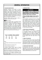
8.1 SPARE PARTS ORDERING PROCEDURE
Ordering Procedure To ensure delivery of your parts, when ordering please quote: · machine serial number · illustration number and item number · part number · part description · quantity required EXAMPLE: If you wanted to order 1 Panfeeder Takeup Bearing, place your order in the following fashion : Machine serial number Illustration number - 8.3.4 Item number - 29 Part number - 11.05.0241 Part description - Tape up Bearing Quantity required - 1 This information will enable us to supply the correct parts with the minimum of delay.
NOTE: For ordering spare parts related to the engine, a parts list issued by the manufacturers has been included with this manual. Follow the procedure as laid down within this parts list.
SP-2
Machine Type
Machine Serial No.
MACHINE DETAILS
Illustration Number Item No.
MANUAL DETAILS Parts No. Part Description
Customer Address
Quantity Required
8.2
Customer Name
Parts Ordering Form
SECTION 8: SPARE PARTS
SPARE PARTS ORDER FORM
SP-3
011003/02
SECTION 8: RESERVEONDERDELEN
010303/01
8.1 Reserveonderdelen en bestelling
Voor een correcte bestelling van reserveonderdelen de volgende gegevens vermelden: · Serienummer van de machine · Tekening- en positienummer · Onderdeelnummer · Onderdeelaanduiding · Bestelhoeveelheid Voorbeeld: bestelling Serienummer van de machine Tekeningnummer -8,30,4 Positienummer -29 Onderdeelnummer -11.05.0241 Onderdeelaanduiding Bestelhoeveelheid - 1 Alleen zo kunnen wij u zo snel mogelijk het juiste onderdeel leveren.
Aanwijzing: Om onderdelen voor de motor te bestellen, is de onderdelenlijst van de motorfabrikant bijgevoegd.
SP-4
Type installatie Serienummer
Gegevens omtrent de machine
Tekeningnummer Positienummer Onderdeelnummer Onderdeelaanduiding
Gegevens omtrent het handboek
Adres
Datum
Bestelhoeveelheid
8.2
Naam
Bestelformulier
SECTION 8: RESERVEONDERDELEN
BESTELFORMULIER
SP-5
010303/01
SECTION 8: PIÈCES DE RECHANGE
010303/01
8.1 Pièces de rechange et approvisionnement
Pour obtenir un approvisionnement correct en pièces de rechange, sans retards, il faut préciser: · Numéro de série de la machine · Repère ou n° de plan · Référence de la pièce · Désignation · Quantité Exemple: COMMANDE Numéro de série de la machine Repère – 8.30,4 N° de plan -29 Référence de la pièce – 11.05.0241 Désignation Quantité - 1 Ces informations nous permettent de fournir la pièce voulue dans les meilleurs délais.
Important: Pour vos approvisionnements en pièces de rechange moteur, nous avons joint la liste des pièces de rechange du constructeur du moteur.
SP-6
N° de plan
Désignation
Référence de la pièce
Repère
Type de machine
Numéro de série
Informations sur le manuel opérateur
Adresse
DATE
Quantité
8.2
Informations sur la machine
Formulaire de commande Nom
SECTION 8: PIÈCES DE RECHANGE
FORMULAIRE DE COMMANDE
SP-7
010303/01
SECTION 8: ERSATZTEILE
010303/01
8.1 ERSATZTEILE UND ERSATZTEILBESTELLUNG
Für eine korrekte und reibungslose Ersatzteilbestellung nennen Sie uns bitte: · Seriennummer der Maschine · Zeichnungs- und Positionsnummer · Teilenummer · Teilebezeichnung · Bestellmenge Beispiel: BESTELLUNG Seriennummer der Maschine Zeichnungsnummer – 8.3.4 Positionsnummer - 29 Teilenummer – 11.05.0241 Teilebezeichnung – Bestellmenge - 1 Nur so ist es uns möglich Ihnen schnellstmöglichst das richtige Teil zu liefern.
Hinweis: Zur Bestellung von Ersatzteilen für den Motor ist die Ersatzteilliste des Motorherstellers beigefügt.
SP-8
Anlagentyp
Seriennummer Zeichnungsnummer
Angaben zur Maschine Positionsnummer
Teilenummer Teilebezeichnung
Angaben zum Betriebsbuch
Anschrift
Datum
Bestellmenge
8.2
Name
Bestellformular
SECTION 8: ERSATZTEILE
BESTELLFORMULAR
SP-9
010303/01
CAPÍTULO 8: REPUESTOS
010303/01
8.1 Repuestos y pedido
Para pedir los repuestos de forma correcta, hay que indicar: · Número de serie de la instalación · Número de dibujo y de posición · Número de la pieza · Denominación de la pieza · La cantidad requerida EJEMPLO: Pedido Número de serie de la instalación Número de dibujo – 8.3.4 Número de posición -29 Número de pieza –11.05.0241 Denominación de la pieza Cantidad requerida - 1 Solo de esta forma es posible abastecer lo más pronto la pieza exacta.
AVISO: Para pedir los repuestos del motor hay que referirse a la anexa lista de repuestos del constructor del motor.
SP-10
Tipo de la instalación
Número de serie
Datos de la máquina
Número de dibujo
Número de posición
Número de piezas
Dirección
Denominación de la pieza
Datos del manual
Fecha
Cantidad requerida
8.2
Nombre
Formulario de pedido
CAPÍTULO 8: REPUESTOS
FORMULARIO DE PEDIDO
SP-11
010303/01
KAPITEL 8: RESERVEDELE
010303/01
8.1 BESTILLING AF RESERVEDELE Bestillingsprocedure. Udfyld venligst følgende felter på bestillingssedlen: · anlæggets serienummer · illustrationsnummer og referencenummer · reservedelsnummer · reservedelsbeskrivelse · antal
EKSEMPEL: Hvis du vil bestille ONE HOPPER REAR CLAMP skal du skrive følgende: Anlæggets serienummer: FTP 500040 Illustrationsnummer: 8.3.15 Referencenummer: 12 Reservedelsnummer: 683.08.04 Reservedelsbeskrivelse: Hopper Rear Clamp Antal: 1 På den måde kan vi levere den korrekte reservedel hurtigst muligt.
BEMÆRK: Der er vedlagt en reservedelsliste fra motorfabrikanten til brug ved bestilling af reservedele til motoren. Følg ovennævnte bestillingsprocedure.
SP-12
Type
HÅNDBOGSSPECIFIKATIONER
Serienummer Illustrationsnr. Referencenr. Reservedelsnr.Beskrivelse
ANLÆGSSPECIFIKATIONER
Kundeadresse
Antal
Dato______________
8.2
Kundenavn
Bestillingsseddel
KAPITEL 8: RESERVEDELE
Bestillingsseddel
SP-13
010303/01
KAPITTEL 8: RESERVEDELER
010303/01
8.1 RESERVEDELER OG ESERVEDELSBESTILLING
For en korrekt og enkel reservedelsbestilling oppgi: · Seriennummer · Tegnings- og posisjonsnummer · Delnummer · Delbetegnelse · Bestillingsmengde EKSEMPEL: BESTILLING Seriennummer - FTP 500040 Tegningsnummer -8.3.4 Posisjonsnummer -29 Delnummer -11,050,0241 Delbetegnelse - Tape up Bearing Bestillingsmengde - 1 Bare på denne måten er det mulig for oss til å levere den riktige delen snarest mulig.
Henvisning: For bestilling av reservedeler for motoren er motorprodusentens reservedelsliste vedagt.
Anleggstype
Serienummer
Angivelser til maskinen
Tegningsnummer Posisjonsnummer Delnummer
Delbetegnelse
Angivelser til instruksjonsboken
Adresse
DATO
Bestillingsmengde
8.2
Navn
Formular bestilling
KAPITTEL 8: RESERVEDELER
FORMULAR BESTILLING
010303/01
CAPITOLO 8: RICAMBI
I 010303/01
8.1 RICAMBI E MODULO D’ORDINE
Per assicurarsi la consegna dei vostri ricambi, si prega di citare: · Numero di serie della macchina · Numero dell’illustrazione e della posizione · Numero del ricambio · Descrizione del ricambio · Quantità ESEMPIO: ORDINE Numero di serie della macchina Numero dell’illustrazione - 8.3.4 Numero della posizione - 29 Numero del ricambio -11.05.0241 Descrizione del ricambio Quantità - 1 Queste informazioni ci consentiranno di fornire il corretto ricambio nel minor tempo possibile.
Avviso: Per ordinare ricambi del motore, è stata inclusa in questo manuale una lista delle parti di ricambio.
Tipo di macchina
Numero di serie Numero del della macchina disegno
Dettagli della macchina Numero della posizione
Numero del ricambio
Indirizzo
Descrizione del ricambio
Dettagli del manuale
Data
Quantità
8.2
Nome
Modulo d’ordine ricambi
CAPITOLO 8: RICAMBI
MODULO D’ORDINE RICAMBI
I 010303/01
KAPITEL 8: RESERVDELAR
S 010303/01
8.1 RESERVDELAR OCH RESERVDELSBESTÄLLNING
För en korrekt och friktionsfri reservdelsbeställning behöver vi: · Maskinens serienummer · Ritnings- och positionsnummer · Komponentnummer · Komponentbeteckning · Beställt antal EXEMPEL: BESTÄLLNING Maskinens serienummer Ritningsnummer –8.3.4 Positionsnummer -29 Komponentnummer – 11.05.0241 Komponentbeteckning Beställt antal - 1 Först nu är det möjligt för oss att så fort som möjligt leverera rätt del till dig.
ANVISNING: För beställning av reservdelar till motorn bifogar vi motortillverkarens reservdelslista
Anläggningstyp Seriennummer
Information om maskinen
Ritningsnummer
Positionsnummer
Komponentnummer Komponentbeteckning
Information om instruktionsboken
Underskrift
Datum
Beställt antal
8.2
Namn
Beställningsblankett
KAPITEL 8: RESERVDELAR
BESTÄLLNINGSBLANKETT
S 010303/01
SECTION 8: SPARE PARTS 8.3 SPARE PARTS INDEX 8.3.1
Chassis European Assembly
8.3.2
Chassis USA Assembly
8.3.3
Panfeeder European Assembly
8.3.4
Panfeeder Cassette Assembly
8.3.5
Panfeeder USA Assembly
8.3.6
Panfeeder Link Arm Assembly
8.3.7
Jackleg Assembly RHS European
8.3.8
Jackleg Assembly RHS USA
8.3.9
Main Telescopic European Assembly
8.3.10 Main Telescopic USA Assembly 8.3.11
Powerunit Assembly
8.3.12 Diesel Tank Assembly 8.3.13 Deutz 2012 Assembly 8.3.14
N/A
8.3.15
N/A
8.3.16
N/A
8.3.17
N/A
8.3.18 Fines Conveyor (Long Conveyor) 8.3.19 Fines Baseunit (Long Conveyor) 8.3.20 1st Element Fines (Long Conveyor) 8.3.21 2nd Element (Long Conveyor) 8.3.22 3rd Element Fines (Long Conveyor) 8.3.23 Screen Subframe Assembly 8.3.24 Screen Shaft Assembly SP-20
011003/02
SECTION 8: SPARE PARTS 8.3.25 Screen -Side Tension/End Tension Assembly 8.3.26
Screen Cascades/Cascades Assembly
8.3.27
Screenbox-PunchPlate/End Tension Assembly
8.3.28
Rhs Screen Access Ladder Assembly
8.3.29
LHS Screen Access Ladder Assembly
8.3.30
Oversize Chutes Assembly
8.3.31
Track Subframe Assembly
8.3.32
Transfer Conveyor General Assembly
8.3.33
Transfer Conveyor Head Section
8.3.34
N/A
8.3.35
Middle Grade Base Unit Support Frame Assembly
8.3.36
Middle Grade Conveyor Base Unit Assembly
8.3.37
N/A
8.3.38
N/A
8.3.39
Middle Grade Conveyor Complete Assembly (Long Conveyor)
8.3.40
1st Element Mid - Grade (Long Conveyor)
8.3.41
3rd Element Mid - Grade (Long Conveyor)
8.3.42
Oversize Conveyor Assembly
8.3.43
Oversize Conveyor First Element
8.3.44
Oversize Conveyor Second Element Assembly
8.3.45
Electrical Components
8.3.46
Hydraulic Circuit Diagram
8.3.47
Hydraulic Diagram
8.3.48
Electric Diagrams
SP-21
011003/02
SECTION 8: SPARE PARTS
8.3.49
Standard Electrical Specification
8.3.50
Desert Electrical Specification
SP-22
011003/02
.
46
21
9
3
25
10
32
13
31
41
37
15
42
46
1
42
46
47
40
33
45
18 17 7
41
46
50
36
23
27
22
34
49
44
38
45
40
6
24
40
45
20
5
19
45
40
35
2
8
CHASSIS EUROPEAN
41
26
39
41
Name:
30
43
29
883.01a
16
49
28
40
45
Figure :
11
4
14
12
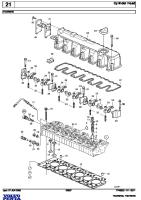
ILLUSTRATION 8.3.1
Rev: A
ILLUSTRATION 8.3.1 Figure :
883.01a
Name:
CHASSIS EUROPEAN
Item
Part No
1
SEE_NOTE_4
0 SEE ELECTRIC DIAGRAM
1
2
SEE_NOTE_4
0 SEE ELECTRIC DIAGRAM
4
3
SEE_NOTE_5
0 SEE HYDRAULIC DIAGRAM
2
4
SEE_NOTE_4
0 SEE ELECTRIC DIAGRAM
1
5
380306050
0 PIN
2
6
380306110
0 PIN
2
7
380308130
0 PIN
3
8
380308150
0 PIN
2
9
380312190
0 380312190 PIN
2
10
883.01.12
2 BANK MNT PLT
2
11
883.01.16
0 DOZER PLT
1
12
883.01.08
0 BOLT ON CMBR
1
13
12.02.0017
0 DRAWBAR PIN
1
14
883.01.17
0 FLAP COVER
1
15
883.01.10A
0 LHS JACKLEG / BF SUPPORT(see illustration 8.3.7)
1
16
883.01.07A
0 RHS JACKLEG / BF SUPPORT(See Illustration 8.3.7)
1
17
883.38.02
0 MAIN HINGE COLLAR
2
18
883.38.01
0 MAIN HINGE PIN
2
19
883.01.19
0 OVERSIZE CMBR
1
20
883.01.20
0 SCREEN LIFT BOX
2
21
883.14.06
0 TRANSPORT BRACKET MG
1
22
683.01.09A
1 DIESEL TANK COMPLETE
1
23
883.01.14
1 LADDER SUPPORT
1
24
883.01.15
1 LADDER SUPPORT
1
25
883.14.05
1 MG TRANSPORT BKT MNT
1
26
883.01.01
3 CHASSIS MWA
1
27
883.14.07
1 MG TRANS BKT
1
Rev:
Rev Description
A
Qty
LONG CONVEYOR OPTION
28
26.44.20060
0 BOLT
8
29
26.44.16050
0 BOLT
4
ILLUSTRATION 8.3.1 Figure :
883.01a
Name:
CHASSIS EUROPEAN
Item
Part No
30
26.44.16040
0 BOLT
8
31
26.44.10040
0 BOLT
4
32
26.44.16050
0 BOLT
4
33
26.44.16050
0 BOLT
4
34
26.44.20060
0 BOLT
6
35
26.44.20175
0 BOLT
2
36
26.44.20110
0 BOLT
4
37
26.44.20060
0 BOLT
16
38
26.44.12040
0 BOLT
4
39
26.44.06040
0 BOLT
1
40
32.02.01020
0 FLAT WASHER
1
41
32.02.01016
0 FLAT WASHER
1
42
32.02.01010
0 FLAT WASHER
1
43
32.02.01006
0 FLAT WASHER
1
44
32.02.01012
0 FLAT WASHER
1
45
26.24.00020
0 NYLOC NUT
1
46
26.24.00016
0 NYLOC NUT
1
47
26.24.00010
0 NYLOC NUT
1
48
26.24.00006
0 NYLOC NUT
1
49
26.24.00012
0 NYLOC NUT
1
50
883.01.24
3 BANK MTG PLT
1
[REPORT END]
Rev:
Rev Description
A
Qty
.
15
11
4
47
13
41
37 25
20
12
10
9
27
24
36
35
1
42
41
47
47
46
28
34
16
40
45
17
21
7
3
22
48
41
26
6
30
46
44
39
31
45
40
33
23
40
45
5
19
18
45
40
32
2
8
CHASSIS USA
44
Name:
14
883.01B
38
Figure :
43
39
29
ILLUSTRATION 8.3.2
Rev: A
ILLUSTRATION 8.3.2 Figure :
883.01B
Name:
CHASSIS USA
Item
Part No
1
SEE_NOTE_4
0 SEE ELECTRIC DIAGRAM
1
2
14.02.0020
0 REMOTE STOP
2
3
SEE_NOTE_5
0 SEE HYDRAULIC DIAGRAM
2
4
SEE_NOTE_4
0 SEE ELECTRIC DIAGRAM
1
5
380306050
0 PIN
2
6
380306110
0 PIN
2
7
380308130
0 PIN
3
8
380308150
0 PIN
2
9
380312190
0 380312190 PIN
2
10
883.01.12
0 BANK MNT PLT
2
11
883.01.16
0 DOZER PLT
1
12
12.02.0017
0 DRAWBAR PIN
1
13
883.01.17
0 FLAP COVER
1
14
883.01.18A
0 JACKLEG LEFT USA (See Illustration 8.3.8)
1
15
883.01.05A
0 JACKLEG RIGHT USA(See Illustration 8.3.8)
1
16
883.38.02
0 MAIN HINGE COLLAR
2
17
883.38.01
0 MAIN HINGE PIN
2
18
883.01.19
0 OVERSIZE CMBR
1
19
883.01.20
0 SCREEN LIFT BOX
2
20
883.14.06
0 TRANSPORT BRACKET MG
1
21
683.01.09A
1 DIESEL TANK COMPLETE
1
22
883.01.14
1 LADDER SUPPORT
1
23
883.01.15
1 LADDER SUPPORT
1
24
883.14.05
1 MG TRANSPORT BKT MNT
1
25
883.01.01
3 CHASSIS MWA
1
26
883.14.07
1 MG TRANS BKT
1
27
26.44.06040
0 BOLT
1
28
26.44.20060
0 BOLT
16
29
26.44.12050
0 BOLT
4
Rev:
Rev Description
A
Qty
ILLUSTRATION 8.3.2 Figure :
883.01B
Name:
CHASSIS USA
Item
Part No
30
26.44.20110
0 BOLT
4
31
26.44.12040
0 BOLT
4
32
26.44.20175
0 BOLT
2
33
26.44.20060
0 BOLT
6
34
26.44.16050
0 BOLT
4
35
26.44.16050
0 BOLT
2
36
26.44.10040
0 BOLT
4
37
26.44.16040
0 BOLT
8
38
32.02.01006
0 FLAT WASHER
1
39
32.02.01012
0 FLAT WASHER
1
40
32.02.01020
0 FLAT WASHER
1
41
32.02.01016
0 FLAT WASHER
1
42
32.02.01010
0 FLAT WASHER
1
43
26.24.00006
0 NYLOC NUT
1
44
26.24.00012
0 NYLOC NUT
1
45
26.24.00020
0 NYLOC NUT
1
46
26.24.00016
0 NYLOC NUT
1
47
26.24.00010
0 NYLOC NUT
1
48
883.01.24
3 BANK MTG PLT
1
[REPORT END]
Rev:
Rev Description
A
Qty
.
13
18
37
29
40 31 37
37
40
40
22
40
8
24 3
40
32
37
26
37
14
40
4
35
33
42
37
25
39
40
23 40 37 21 27
34 20
PANFEEDER EUROPEAN
11
12
2
37
36
Name:
30
1
7
28
16
17
883.08A
9
5
6
38
Figure :
15
10
27
41
19
ILLUSTRATION 8.3.3
Rev: A
ILLUSTRATION 8.3.3 Figure :
883.08A
Name:
PANFEEDER EUROPEAN
Item
Part No
1
12.02.0025
0 HINGE
2
380308140
0 PIN
2
3
381508140
0 381508140 PIN
2
4
683.10.15
0 BACK CLAMP
1
5
20.883.08.01
0 BACK RUBBER
1
6
883.08.23
0 DOOR GUIDE
7
7
883.08.24
0 DOOR STAY
7
8
883.08.15
0 HOOD
2
9
10.28.0713
0 HYDRAULIC RAM
2
10
883.08.21
0 REAR DOOR MWA
1
11
883.08.27
0 SHIELD
1
12
883.08.20
0 SIDE DOOR MWA
6
13
883.08.11
0 TELESCOPIC BOSS
2
14
20.883.08.02
1 B/F SCREEN RUBBER
1
15
883.04.17
1 CLAMP
1
16
883.08.28
1 HOPPER EXTENSION
1
17
883.08.29
1 LHS HOPPER EXTENSION
1
18
883.08.12
1 PIN WASHER
2
19
883.08.30
1 REAR EXTENSION
1
20
883.08B
2 APRON CASSETTE(See Illustration 8.3.4)
1
21
883.08.25
2 LHS DRIVE GUARD
1
22
883.08.26
4 RHS DRIVE GUARD
1
23
883.08.18
5 FOLD DOWN SIDE-LEFT
1
24
883.08.01
3 BELTFEEDER MWA
1
25
883.08.02
3 BF TELESCOPIC
2
26
883.08.17
4 FOLDING SIDE RIGHT
1
27
26.44.16060
0 BOLT
6
28
26.44.12050
0 BOLT
4
29
26.44.12040
0 BOLT
2
Rev Description
Rev:
A
Qty
14
ILLUSTRATION 8.3.3 Figure :
883.08A
Name:
PANFEEDER EUROPEAN
Item
Part No
30
26.44.12045
0 BOLT
3
31
26.44.12040
0 BOLT
6
32
26.54.12045
0 COUNTER SUNK SOCKET HEAD
3
33
26.44.12060
0 BOLT
5
34
26.44.12040
0 BOLT
6
35
26.44.20090
0 BOLT
2
36
26.44.12040
0 BOLT
14
37
32.02.01012
0 FLAT WASHER
1
38
32.02.01016
0 FLAT WASHER
1
39
32.02.01020
0 FLAT WASHER
1
40
26.24.00012
0 NYLOC NUT
1
41
26.24.00016
0 NYLOC NUT
1
42
26.24.00020
0 NYLOC NUT
1
[REPORT END]
Rev Description
Rev:
A
Qty
.
9
58
47
25
46
54
29
49
5
15
58
39
4
27
54
45
2
16
67
57
7
13
23
30
52
11
36
54
10
12
22
44
54
37
58
50
58
43
60
56
42
35
55
17
54
59
26 28
54
51
31
53
6
34
40
24
21
38
14
1
18
67
61 62
68
63 64 65 66
PANFEEDER CASSETTE
8
54
48
Name:
20
3
58
883.08B
32
41
A 1:20
Figure :
33
DETAIL SCALE
19
ILLUSTRATION 8.3.4
Rev: B
ILLUSTRATION 8.3.4 Figure :
883.08B
Name:
PANFEEDER CASSETTE
Item
Part No
1
883.08.03
2 APRON PAN
2
SEE_NOTE_1
0 SEE BOLT DIAGRAM
4
3
883.08.08
2 ADJUSTER BLOCK
2
4
883.08.09
0 ADJUSTER SLEEVE
2
5
11.05.0226
0 BEARING
4
6
11.05.0240
0 BEARING
2
7
12.11.0058
0 BELLEVILLE WASHER
Rev:
Rev Description
B
Qty
62
56
ORIGINALLY 20 PER SIDE, INCR. TO 28 TO ALLOW MORE TRAVEL
8
883.08.32
0 CASSETTE GUARD- SHORT
4
9
883.08.31
0 CASSETTE GUARD-LONG
4
10
12.94.0001
0 PANFEEDER ROLLER
11
13.06.4215
0 FLANGE COUPLING
1
12
10.27.1025
0 GEARBOX C/W COLLAR
1
13
10.25.4220
0 MOTOR
1
28
Up to Ser. No. FRT540262 (plus the following machines FRT540268 & FRT540274)
13
10.25.5220
0 HYDRAULIC MOTOR
1
From Serial No. FRT540263 (Plus Serial No. FRT540256)
14
KEY_MET_28X16X
0 KEY
2
15
1BSW.NUT
0 PLAIN NUT
4
16
883.08.10
0 RETURN WHEEL
4
17
883.08.36
0 ROSTA CLAMP
1
18
883.08.34
1 ROSTA MNT BCKT
2
19
11.05.0241
0 TAKE UP BEARING
2
20
13.04.9380
0 TAPERLOCK BUSH
2
21
13.04.9385
0 TAPERLOCK BUSH
2
MUST BE ORDERED WITH 883.08.04, FOR CORRECT ALIGNMENT
22
883.08.47
1 TORQUE ARM SUPPORT
1
23
883.08.43
1 U/SIDE GUARD DRI END
1
24
883.08.44
1 U/SIDE GUARD DRI END
1
25
883.08.37
0 U/SIDE GUARD IDLER END
1
26
883.08.38
0 U/SIDE GUARD IDLER END
1
27
883.08.39
0 U/SIDE GUARD MIDDLE
1
ILLUSTRATION 8.3.4 Figure :
883.08B
Name:
PANFEEDER CASSETTE
Item
Part No
28
883.08.40
0 U/SIDE GUARD MIDDLE
1
29
883.08.07
1 ADJUSTER BAR
2
30
883.18.03
1 APRON RETURN ROLLER SHAFT
2
31
883.08.04
1 DRIVE SPROCKET
2
Rev:
Rev Description
B
Qty
MUST BE ORDERED WITH 13.04.9385, FOR CORRECT ALIGNMENT
32
883.18.01
2 IDLER SHAFT
1
33
883.08.05
1 IDLER SPROCKET
2
34
20.883.08.03
1 PAN SCRAPER
1
35
883.08.35
1 SCRAPER MNT
1
36
883.08.48
1 TORQUE ARM ASSY
1
37
883.08.03
2 APRON PAN
38
883.18.02
5 DRIVE SHAFT
39
883.08.06
40
13.10.0227
0 ROSTA TENSIONER
2
41
26.44.12080
0 BOLT
2
42
26.44.16070
0 BOLT
8
12 APRON CASSETTE MWA
62 1 1
4 PER BEARING
43
26.44.20060
0 BOLT
5
44
26.44.12140
0 BOLT
10
45
26.50.10035
0 CAP HEAD SCREW
4
46
26.44.12060
0 BOLT
4
47
26.44.12030
0 BOLT
16
48
13.05.0064
0 NUT, BOLT, WASHER
496
8 PER APRON
49
26.44.12045
0 BOLT
16
3 OFF GUARDS 23, 24, 27, 28. 2 OFF GUARDS 25, 26
50
26.44.12050
0 BOLT
4
51
26.44.12030
0 BOLT
4
52
26.44.12065
0 BOLT
112
4 PER ROLLER
53
26.44.12060
0 BOLT
4
54
32.02.01012
0 FLAT WASHER
184
55
32.02.01016
0 FLAT WASHER
16
ILLUSTRATION 8.3.4 Figure :
883.08B
Name:
PANFEEDER CASSETTE
Item
Part No
56
32.02.01020
0 FLAT WASHER
57
32.04.01010
0 SPRING WASHER
58
26.24.00012
0 NYLOC NUT
39
59
26.24.00016
0 NYLOC NUT
8
60
26.24.00020
0 NYLOC NUT
5
61
10.01.1101
0 M/M ADAPTOR
1
62
10.12.0023
0 BONDED SEAL
1
63
88310/13
0 GREASE PIPE
2
Rev:
Rev Description
B
Qty 10 4
DRIVE DRUM
63
88310/14
0 GREASE PIPE
2
IDLER DRUM
63
88310/16
0 GREASE PIPE
2
UNDERSIDE BEARING (3378mm LONG)
63
88310/18
0 GREASE PIPE
2
UNDERSIDE BEARING (2108mm LONG)
64
10.02.1206
0 90 BLOCK ELBOW
1
65
10.03.1100
0 1/8 M/F BULKHEAD ADAPTER
1
66
31.18.02000
0 GREASE NIPPLE
1
67
12.00.1111
0 CIRCLIP
2
[REPORT END]
1
17
12
41
18
40
13
23
4
DETAIL SCALE
44
39
A 1:20
2
24
6
41 44 38 41
31
28
44
33
44 41
42 45
19
30
5
14
37
44
41
36
8 34
22
10
43 46 29 44
21
41 27 35 26
25
PANFEEDER USA
20
44
9
Name:
7
41
15
883.08C
3
32
47
Figure :
16
11
ILLUSTRATION 8.3.5
Rev: B
ILLUSTRATION 8.3.5 Figure :
883.08C
Name:
PANFEEDER USA
Item
Part No
1
12.02.0025
0 G2929 6" X 1/2" HINGE
2
883.08.45
0 U/SIDE GUARD DRIVE REAR
1
3
380308140
0 380308140 PIN
2
4
380312160
0 380312160 PIN
2
5
683.10.15
0 BACK CLAMP
1
6
20.883.08.01
0 BACK RUBBER
1
7
883.08.24
0 DOOR STAY
7
8
883.08.51
0 FRONT HOPPER EXTENSION
1
Rev:
Rev Description
B
Qty
14
UPTO SERIAL NO: FRT540348
8
883.41.05
0 RHS FLAP EXTENSION
1
FROM SERIAL NO: FRT540349
9
883.08.52
0 FRONT HOPPER EXTENSION
1
UPTO SERIAL NO: FRT540348
9
883.41.04
0 LHS FLAP EXTENSION
1
FROM SERIAL NO: FRT540349
10
883.08.15
0 HOOD
2
11
883.08.50
0 HOPPER EXTENSION END
1
UPTO SERIAL NO: FRT540348
11
883.41.03
0 REAR FLARED EXTENSION
1
FROM SERIAL NO: FRT540349
12
10.28.0713
0 HYDRAULIC RAM - CLOSED 1500/ STROKE 1320
2
13
883.08.19
0 LINK ARM MNT LHS
1
14
883.08.22
0 LINK ARM MNT RHS
1
15
883.08.49
0 LONG HOPPER SIDE EXTENSION
2
UPTO SERIAL NO:FRT540348
15
883.41.02
0 RHS FLARED EXTENSION
1
FROM SERIAL NO:FRT540349
16
883.08.21
0 REAR DOOR MWA
1
17
883.08.20
0 SIDE DOOR MWA
6
18
883.08.11
0 TELESCOPIC BOSS
2
19
20.883.08.02
1 B/F SCREEN RUBBER
1
20
883.04.17
1 RUBBER CLAMP
1
21
883.08.53
1 END EXTENSION PLT
1
22
883.08.54
1 FRONT END PLATE
1
ILLUSTRATION 8.3.5 Figure :
883.08C
Name:
PANFEEDER USA
Item
Part No
23
883.08.12
1 PIN WASHER
2
24
883.08.27
2 SHIELD
1
25
883.08B
3 APRON CASSETTE
1
26
883.08.02
3 BF TELESCOPIC
2
27
883.08.25
3 LHS DRIVE GUARD
1
28
883.08.26
4 RHS DRIVE GUARD
1
29
883.08.18
5 FOLD DOWN SIDE-LEFT
1
30
883.08.17
5 FOLDING SIDE RIGHT
1
31
883.08.01
7 BELTFEEDER MWA
1
32
26.44.12040
0 SET SCREW
4
33
26.44.16060
0 16 X 60 8.8 SET SCREW
34
26.44.20090
0 SET SCREW
2
35
26.44.12040
0 SET SCREW
6
36
26.54.12045
0 COUNTER SUNK SOCKET HEAD
3
37
26.44.12060
0 SET SCREW
5
38
26.44.12040
0 SET SCREW
6
39
26.44.12045
0 SET SCREW
3
40
26.44.12040
0 SET SCREW
2
41
32.02.01012
0 FLAT WASHER
1
42
32.02.01016
0 FLAT WASHER
1
43
32.02.01020
0 FLAT WASHER
1
44
26.24.00012
0 M12 NYLOC NUT
1
45
26.24.00016
0 M16 NYLOC NUT
1
46
26.24.00020
0 M20 NYLOC NUT
1
47
883.08.49
0 LONG HOPPER SIDE EXTENSION
1
Rev:
Rev Description
B
Qty
14
UPTO SERIAL NO: FRT540348
47
883.41.01
0 LHS FLARED EXTENSION FROM SERIAL NO: FRT540349
[REPORT END]
1
.
ILLUSTRATION 8.3.6 Figure :
883.30.04
Name:
PANFEEDER LINK ARM
Rev:
A
ILLUSTRATION 8.3.6 Figure :
883.30.04
Name:
PANFEEDER LINK ARM
Item
Part No
Description
1
883.30.04
BF LINK ARM
[REPORT END]
Rev:
A
Qty 1
ILLUSTRATION 8.3.7 Figure :
883.01.07A
Name:
JACKLEG ASSEMBLY RHS EUROPEAN
Rev:
A
ILLUSTRATION 8.3.7 Figure :
883.01.07A
Name:
JACKLEG ASSEMBLY RHS EUROPEAN
Item
Part No
1
883.01.07
3 BF TELESCOPIC/WHEEL
1
2
883.01.04
2 RUNNING WHEEL
1
3
883.01.09
1 BF STOP
1
4
883.01.11
1 JACKING LEG INNER
1
5
10.28.0711
0 HYDRAULIC RAM
1
6
380308180
0 PIN
1
7
381408150
0 381408150 PIN
1
8
381412230
0 381412230 PIN
1
9
12.15.0075
0 BALL BEARING
1
10
12.11.0001
0 SPRING
1
11
10.12.0027
0 3/4" BONDED SEAL
1
12
10.09.0018
0 3/4 MALE BLANKING PLUG
1
[REPORT END]
Rev Description
Rev:
A
Qty
Figure : JACKLEG ASSEMBLY RHS USA VERSION
883.01.05A
ILLUSTRATION 8.3.8
Name:
Rev:
A
ILLUSTRATION 8.3.8 Figure :
883.01.05A
Name:
JACKLEG ASSEMBLY RHS USA VERSION
Item
Part No
Description
1
883.01.05
LINK ARM HEEL LEFT
1
2
883.01.11
JACKING LEG INNER
1
3
10.28.0711
HYDRAULIC RAM
1
4
12.09.1002
DMP 520 RUBBERSTOP
1
5
381408150
381408150 PIN
1
6
380308180
380308180 PIN
1
7
380312160
380312160 PIN
1
8
12.15.0075
BALL BEARING
1
9
12.11.0001
SPRING
1
10
10.12.0027
3/4" BONDED SEAL
1
11
10.09.0018
3/4 MALE BLANKING PLUG
1
[REPORT END]
Rev:
A
Qty
ILLUSTRATION 8.3.9 Figure :
883.30.01A
Name:
MAIN TELESCOPICS EUROPEAN
Rev:
A
ILLUSTRATION 8.3.9 Figure :
883.30.01A
Name:
MAIN TELESCOPICS EUROPEAN
Item
Part No
1
883.30.01
2 SCREEN LIFT OUTER-EURO
1
2
883.30.02
2 SCREEN TELE INNER
2
3
10.28.0106
0 HYDRAULIC RAM
2
4
883.30.07
0 SPACER BUSH
2
5
380308110
0 PIN
2
6
380308140
0 PIN
2
7
381512170
0 PIN
2
8
32.02.01024
0 FLAT WASHER
6
9
26.44.24070
0 BOLT
2
10
26.24.00024
0 NYLOC NUT
2
[REPORT END]
Rev Description
Rev:
A
Qty
ILLUSTRATION 8.3.10 Figure :
883.30.01B
Name:
MAIN TELESCOPICS USA
Rev:
A
ILLUSTRATION 8.3.10 Figure :
883.30.01B
Name:
MAIN TELESCOPICS USA
Item
Part No
1
883.30.03
1 SCREEN LIFT OUTER-USA
1
2
883.30.02
2 SCREEN TELE INNER
2
3
10.28.0104
0 HYDRAULIC RAM
2
4
883.30.07
0 SPACER BUSH
2
5
32.02.01024
0 FLAT WASHER
6
6
26.44.24070
0 BOLT
2
7
26.24.00024
0 NYLOC NUT
2
8
380308110
0 PIN
2
9
380308140
0 PIN
2
10
381512170
0 PIN
2
[REPORT END]
Rev Description
Rev:
A
Qty
59
71
62
69
19
75
35
47
58
60
42
68
71
30
75
72
2
37
16
61
71
8
71
73
75
75
69
78
63
7
79
20
75
43
64
71
9 14
52
SEE DETAIL A
41
18
6
76
77
25
71
11
4
75
65
73
10
56
53
69
39
57
44 21
45
48
26
13
31
29
24
49 50 38
27 28
DETAIL A
51
17 3
POWERUNIT 883
22
66
70
75
Name:
1
5
70
32
71
683.17C
33
67
75
36
15
Figure :
34
46
12
40
71
54
55
ILLUSTRATION 8.3.11
Rev: A
ILLUSTRATION 8.3.11 Figure :
683.17C
Name:
POWERUNIT 883
Item
Part No
1
10.21.5102
0 SUCTION FILTER
5
2
12.02.0025
0 HINGE
8
3
14.02.0020
0 REMOTE STOP
2
4
10.35.0007
0 OIL COOLER
1
5
10.21.3403
0 RETURN FILTER (ELEMENT 10.21.3402)
2
6
SEE_NOTE_4
0 SEE ELECTRIC DIAGRAM
1
7
683.17.108
0 TWIN FUEL FILTERS MTG PLT
1
8
683.17.60
0 2012C EXHAUST MTG
1
9
683.17.107
0 PRE-FUEL FILTER MTG PLT
1
10
SEE_NOTE_3
0 SEE ENGINE DIAGRAM
1
11
683.17.71
0 883 EXHAUST FOR 2012
1
12
10.23.6652
0 FLOAT LEVEL SWITCH
1
13
683.17.31
1 AIRFILTER & COOLER INTAKE GUARD
2
14
SEE_NOTE_3
0 SEE ENGINE DIAGRAM
1
15
683.17.69
0 CLAMP
1
16
683.17.05
0 POWERUNIT ACCESS DOOR
1
17
10.16.5342
0 CTRL VALVE
1
18
683.17.73
0 DETACHABLE CMBR
1
19
683.17.13
0 ENGINE ACCESS DOOR
1
20
683.17.35
5 ENGINE MNT
1
21
SEE_NOTE_4
0 SEE ELECTRIC DIAGRAM
1
22
20.683.12.02
0 HYDRUALIC TANK RUBBER MNT
2
24
683.17.106
0 WATER CAP COVER
1
25
683.17.72
0 ROOF SUPPORT
1
26
683.17.40
0 SERVICE ACCESS DOOR RHS
1
27
10.16.5308
0 SPOOL REV.S/BOX
2
28
10.16.5384
0 CONTROL VALVE
1
29
663.17.07
0 WEBTEC MNT
4
30
683.17.04
0 WEBTEC MTG PANEL
1
Rev:
Rev Description
A
Qty
ILLUSTRATION 8.3.11 Figure :
683.17C
Name:
POWERUNIT 883
Item
Part No
31
683.17.55
1 POWER UNIT ROOF (2012C)
1
32
683.17.06
1 EXHAUST COVER
1
33
20.683.12.01
1 HYD TANK SEAL
1
34
683.12.02
1 HYDRAULIC TANK LID
1
35
683.12.01
1 HYDRAULIC TANK MWA
1
36
20.683.17.02
1 P.UNIT PROTECTIVE RUBBER
1
37
683.29.01
1 RETURN MANIFOLD ASSY
1
38
683.17.09
1 START BOX MTG PANEL
1
39
683.17.37
0 AIR OUTLET DOOR WELDED ASSY
1
40
683.17.02
3 HYDRAULIC TANK GUARD
1
41
683.17.01
7 POWER UNIT FRAME
1
42
10.09.0014
0 ½" MALE BLANKING PLUG
1
43
SEE_NOTE_3
0 SEE ENGINE DIAGRAM
1
44
000.14.01
0 BATTERY BOX
1
45
12.87.0683
0 DOCUMENT HOLDER
1
46
10.22.5010
0 FILLER CAP
1
47
10.23.5008
0 LEVEL & TEMP GAUGE
1
48
15.02.0793
0 PRE CLEANER
1
49
10.16.6115
0 FLOW DIVIDER
2
50
SEE_NOTE_4
0 SEE ELECTRIC DIAGRAM
1
51
SEE_NOTE_3
0 SEE ENGINE DIAGRAM
1
52
10.16.4583
0 SOLENOID VALVE
1
53
SEE_NOTE_4
0 SEE ELECTRIC DIAGRAM
1
54
26.44.12045
0 BOLT
4
55
26.44.12045
0 BOLT
4
56
26.44.10040
0 BOLT
2
57
26.44.08040
0 BOLT
4
58
26.44.06100
0 BOLT
4
59
26.44.12040
0 BOLT
3
Rev:
Rev Description
A
Qty
ILLUSTRATION 8.3.11 Figure :
683.17C
Name:
POWERUNIT 883
Item
Part No
60
26.44.12040
0 BOLT
4
61
26.44.12035
0 BOLT
3
62
26.44.08030
0 BOLT
4
63
26.44.12045
0 BOLT
4
64
26.44.12045
0 BOLT
4
65
26.44.12040
0 BOLT
10
66
26.44.08030
0 BOLT
8
67
26.44.10030
0 BOLT
14
68
32.02.01006
0 FLAT WASHER
1
69
32.02.01008
0 FLAT WASHER
1
70
32.02.01010
0 FLAT WASHER
1
71
32.02.01012
0 FLAT WASHER
1
72
26.24.00006
0 NYLOC NUT
1
73
26.24.00008
0 NYLOC NUT
1
74
26.24.00010
0 NYLOC NUT
1
75
26.24.00012
0 NYLOC NUT
1
76
14.77.0500
0 BATTERY ISOLATOR SWITCH
1
Rev:
Rev Description
A
Qty
FROM SERIAL NO:FRT540509 ECO1753
77
683.17.134
0 BATTERY ISOLATOR BRACKET
1
FROM SERIAL NO:FRT540509 ECO1753
78
12.17.0070
0 EXHAUST CLAMP
1
79
683.17.201
0 UNIVERSAL CONTROL BANK MTG PLATE
1
(OPTION)
[REPORT END]
Figure : DIESEL TANK
683.01.09A
ILLUSTRATION 8.3.12
Name:
Rev:
A
ILLUSTRATION 8.3.12 Figure :
683.01.09A
Name:
DIESEL TANK
Item
Part No
Description
1
12.01.0013
FUEL FILLER CAP
1
2
12.75.0005
FUEL GAUGE 72 GAL
1
3
12.01.0012
FUEL TANK
1
4
000.13.01
FUEL TANK METAL STRAP
2
5
20.000.13.01
FUEL TANK PADDING RUBBER
4
6
683.01.09
FUEL TANK MOUNTING
1
7
20.000.13.02
TANK RUBBER
2
[REPORT END]
Rev:
A
Qty
ILLUSTRATION 8.3.13 Figure :
883.17.35D
Name:
DEUTZ 2012 ENGINE
Rev:
A
ILLUSTRATION 8.3.13 Figure :
883.17.35D
Name:
DEUTZ 2012 ENGINE
Item
Part No
1
683.17.56
0 683 2012C EXHAUST PIPE 1
1
2
12.17.0056
0 EXHAUST CLAMP
2
3
683.17.112
0 FLEXI - EXHAUST PIPE
1
4
000.17.01
0 EXHAUST SILENCER BOX
1
5
683.17.57
0 EXHAUST 90 DEG BEND
1
6
15.02.0784
0 STRAINER
1
Rev:
Rev Description
A
Qty
From Sr No FRT 540313 ECO 1321
8
683.17.52
1 AIRPIPE
1
9
15.02.0089
0 AIR FILTER COMPLETE
1
10
15.02.0793
0 PRE CLEANER
1
11
15.02.0785
0 WATER TRAP
1
from Sr. No. FRT540313
12
15.02.0114
0 FILTER
1
From Sr No FRT540313
13
15.02.2022
0 BF4M2012 DEUTZ ENGIN
1
From Sr. No.FRT540313
14
000.17.03
0 THROTTLE MNT BCKT
1
15
15.02.0330
0 THROTTLE CABLE
1
16
15.02.0799
0 AIR FILTER ELEMENT
1
17
15.02.0798
0 AIR FILTER SAFETY ELEMENT
1
18
15.35.0097
0 PUMP MOUNTING PLATE
1
19
15.35.0084
0 COUPLING HUB
1
20
15.35.0072
0 FLWHEEL COUPLING FLANGE
1
21
12.14.3005
0 BATTERY
1
22
12.09.5010
0 RUBBER ENGINE MOUNT
4
23
15.02.0795
0 OIL FITER
1
24
12.17.0057
0 EXHAUST CLAMP
2
FROM SERIAL NO:FRT540337 ECO1369
25
12.17.0057
0 EXHAUST CLAMP FROM SERIAL NO:FRT540337 ECO1369
[REPORT END]
2
ILLUSTRATION 8.3.18 Figure :
883.06P
Name:
FINES CONVEYOR (LONG CONVEYOR)
Rev:
16
15
8
14 3
5 13
12
2
4
1
11 10 7
9 6
A
ILLUSTRATION 8.3.18 Figure :
883.06P
Name:
FINES CONVEYOR (LONG CONVEYOR)
Item
Part No
1
883.06V
Rev Description
0 FINES BASEUNIT (LONG CONV)
Rev:
A
Qty
1
(see illustration 8.3.19)
2
883.06S
0 1ST ELEMENT FINES (LONG CONV)
1
(see illustration 8.3.20)
3
883.06M
0 2ND ELEM FINES & MIDGRADE (LONG CONV)
1
(see illustration 8.3.21)
4
883.06.71
0 TELESCOPIC OUTER
1
TO SERIAL NO. FRT 530230
4
883.06.71
2 TELESCOPIC OUTER
1
FROM SERIAL NO. FRT 530231
5
10.28.0158
0 HYDRAULIC RAM
5
6
883.06.18
3 TELESCOPIC INNER MG
2
TO SERIAL NO. FRT 530230
6
883.06.18
5 TELESCOPIC INNER MG
2
FROM SERIAL NO. FRT 530231
7
693.30.05
0 STOPPER
4
TO SERIAL NO. FRT 530230
7
883.06.95
2 STOPPER
4
FROM SERIAL NO. FRT 530231
8
883.06N
1 3RD ELEMENT FINES (LONG CONV)
1
(see illustration 8.3.22)
9
380308110
0 PIN
2
10
380308160
0 PIN
2
11
380308120
0 PIN
9
12
380308150
0 PIN
3
13
380308130
0 PIN
2
14
380308100
0 PIN
2
15
20.03.88308
0 FINES EXTENDED BELT
1
16
20.03.88310
0 FINES CHEVRON BELT
1
OPTIONAL
[REPORT END]
45
51
53
16
53
51
35
53
55 47
51
1
44
51
3
13
50
15
39
48
14
51
21
49 51
10
53
56
53
53
32
7
43
25 9
51
53
26
51
33
42
40
17
52
24
31
54
12
30
53
27
23
34
51
6
41
29
28
5
22
2
FINES BASEUNIT (LONG CONVEYOR)
46
53
4
38
20
Name:
36
37
51
883.06V
8
51
19
Figure :
18
57
58
59
60
61
62
11
ILLUSTRATION 8.3.19
Rev: A
ILLUSTRATION 8.3.19 Figure :
883.06V
Name:
FINES BASEUNIT (LONG CONVEYOR)
Item
Part No
1
883.06.09
0 ADJUSTER RHS
1
2
883.06.10
0 ADJUSTER LHS
1
3
883.06.11
0 ADJUSTER BAR
2
4
20.883.06.01
0 BACK RUBBER
1
5
683.24.25
0 BASE RETURN CLAMP
1
6
19.22.4019
0 CENTRE ROLLER
3
7
19.30.0895
0 DISC RTN ROLLER
1
8
693.18.02
0 IDLER DRUM
1
9
20.883.06.02
0 FEEDBOOT HOPPER SIDE RUBBER
2
10
20.883.06.03
0 FEEDBOOT LINER
1
11
20.883.06.04
0 FEEDBOOT LINER
1
12
883.06.58
0 MG FRONT GUARD
1
13
883.06.24
0 PLOUGH SCRAPER MNT
1
14
883.06.25
0 PLOUGH SCRAPER MNT
1
15
883.06.34
0 REAR CLAMP
1
16
883.06.20
0 RIGHT GUARD
1
17
883.06.26
0 LEFT GUARD
1
18
883.06.27
0 REAR GUARD
1
19
883.06.50
0 REAR RUBBER CLAMP
1
20
883.06.51
0 SIDE RUBBER CLAMP
2
21
883.06.37
0 REMOVABLE CMBR
1
22
20.683.24.07
0 BASE RETURN SCRAPER
1
23
19.22.0023
0 ROLLER BASE PLT
3
24
20.883.06.05
0 SCRAPER RUBBER
1
25
693.24.09
0 SIDE CLAMP
2
26
883.06.49
0 UNDERSIDE GUARD
2
27
663.03.19
0 V-SCRAPER CLAMP
2
28
19.22.4021
0 WING ROLLER
6
29
883.06.07
1 BOLT ON CMBR
1
Rev Description
Rev:
A
Qty
ILLUSTRATION 8.3.19 Figure :
883.06V
Name:
FINES BASEUNIT (LONG CONVEYOR)
Item
Part No
30
883.06.54
1 FINES PADDLE LEFT
1
31
883.06.55
1 FINES PADDLE RIGHT
1
32
883.06.06
2 BASE UNIT MWA
1
33
883.06.12
2 MG FEEDBOOT MWA
1
34
883.06.22
2 SIDE GUARD LHS
1
35
883.06.21
2 SIDE GUARD RHS
1
36
11.02.0250
0 PILLOW BLOCK BEARING
2
37
26.44.12040
0 BOLT
4
38
26.44.12040
0 BOLT
6
39
26.44.12040
0 BOLT
12
40
26.44.12040
0 BOLT
6
41
26.44.12040
0 BOLT
4
42
26.44.16060
0 BOLT
8
43
26.44.12040
0 BOLT
6
44
26.44.12040
0 BOLT
4
45
26.44.12045
0 BOLT
8
46
26.44.12040
0 BOLT
8
47
26.44.20100
0 BOLT
4
48
26.44.12050
0 BOLT
3
49
26.44.12045
0 BOLT
12
50
26.44.12045
0 BOLT
4
51
32.02.01012
0 FLAT WASHER
1
52
32.02.01016
0 FLAT WASHER
16
53
26.24.00012
0 NYLOC NUT
1
54
26.24.00016
0 NYLOC NUT
8
55
26.24.00020
0 NYLOC NUT
4
56
30.22.00016
0 1" HEX NUT
1
57
31.18.02000
0 GREASE NIPPLE
2
58
10.03.1100
0 1/8 M/F BULKHEAD ADAPTER
2
Rev Description
Rev:
A
Qty
ILLUSTRATION 8.3.19 Figure :
883.06V
Name:
FINES BASEUNIT (LONG CONVEYOR)
Item
Part No
59
10.02.1206
0 90 BLOCK ELBOW
2
60
88310/11
0 GREASE PIPE
2
61
10.12.0023
0 BONDED SEAL
2
62
10.01.1101
0 M/M ADAPTOR
2
[REPORT END]
Rev Description
Rev:
A
Qty
ILLUSTRATION 8.3.20
13
14
11
8
5
2
1
4
10
7
Rev:
3
1ST ELEMENT FINES (LONG CONVEYOR)
12
Name:
9
883.06S
6
Figure :
A
ILLUSTRATION 8.3.20 Figure :
883.06S
Name:
1ST ELEMENT FINES (LONG CONVEYOR)
Item
Part No
1
19.22.4019
0 CENTRE ROLLER
2
2
883.06.67
0 REMOVEABLE CMBR
1
Rev Description
Rev:
A
Qty
UPTO SERIAL NO:FRT550558 ECO2118
2
883.06.67
3 REMOVEABLE CMBR
1
FROM SERIAL NO:FRT550559 ECO2118
3
19.22.0023
0 ROLLER BASE PLT
2
4
19.22.4021
0 WING ROLLER
4
5
883.06.02
7 1ST ELEMENT MWA
1
6
12.08.0002
0 8MM "U" BOLT
2
7
26.44.12040
0 BOLT
4
8
26.44.20050
0 BOLT
4
9
32.02.01008
0 FLAT WASHER
4
10
32.02.01012
0 FLAT WASHER
8
11
32.02.01020
0 FLAT WASHER
8
12
26.24.00008
0 NYLOC NUT
4
13
26.24.00012
0 NYLOC NUT
4
14
26.24.00020
0 NYLOC NUT
4
[REPORT END]
ILLUSTRATION 8.3.21 883.06M
Name:
2ND ELEMENT LONG CONVEYOR
Rev:
14
17
20
4
3
8
9
15
13
1
16
19
18
7
2
10
12
17
16
20
19
6
5
21
11
17
20
Figure :
A
ILLUSTRATION 8.3.21 Figure :
883.06M
Name:
2ND ELEMENT LONG CONVEYOR
Item
Part No
1
19.22.4019
0 CENTRE ROLLER
2
2
19.30.0895
0 DISC RTN ROLLER
1
3
19.22.0023
0 ROLLER BASE PLT
2
4
19.22.4021
0 WING ROLLER
4
5
883.06.61
1 2ND ELEMENT MWA
1
6
883.06.66
1 REMOVEABLE CMBR
1
Rev Description
Rev:
A
Qty
UPTO SERIAL NO:FRT550558 ECO2118
6
883.06.66
4 REMOVEABLE CMBR
1
FROM SERIAL NO:FRT550559 ECO2118
7
000.03.02
2 NIPGUARD-DISK 800MM
1
8
883.06.08
3 1ST ELE. REMOVABLE CMBR
1
UPTO SERIAL NO:FRT550558 ECO2118
8
883.06.08
6 1ST ELE. REMOVABLE CMBR
1
FROM SERIAL NO:FRT550559 ECO2118
9
12.08.0002
0 8MM "U" BOLT
4
10
26.44.12040
0 BOLT
8
11
26.44.20050
0 BOLT
2
12
26.44.20065
0 BOLT
4
13
26.44.12045
0 BOLT
2
14
26.44.20050
0 BOLT
4
15
32.02.01008
0 FLAT WASHER
8
16
32.02.01012
0 FLAT WASHER
1
17
32.02.01012
0 FLAT WASHER
1
18
26.24.00008
0 NYLOC NUT
8
19
26.24.00012
0 NYLOC NUT
1
20
26.24.00020
0 NYLOC NUT
1
21
12.08.0006
0 M10 'U' BOLT
2
[REPORT END]
14
7
6
15
11 25
2
39
38
44
39 3 35
34 38 43
38
9
30
8 43
43
38
22
33
13
28
42 37
18
20
45
32
41
45
43
31
38
40
38
40
17
29
36
3RD ELEMENT FINES (LONG CONVEYOR)
44
19
12
4
Name:
43
26
21
5
27
16
883.06N
10
38
24
47
49
51
Figure :
1
23
43
38
46
48
50
ILLUSTRATION 8.3.22
Rev: A
ILLUSTRATION 8.3.22 Figure :
883.06N
Name:
3RD ELEMENT FINES (LONG CONVEYOR)
Item
Part No
1
10.25.4210
Rev Description
0 HYDRAULIC MOTOR
Rev:
A
Qty
1
Up to Ser. No. FRT540262 (plus the following machines FRT540268 & FRT540274)
1
10.25.5210
0 HYDRAULIC MOTOR
1
From Serial No. FRT540263 (Plus Serial No. FRT540256)
2
532.18.01
0 DRIVE DRUM
1
3
11.05.0223
0 BEARING
2
4
19.22.4019
0 CENTRE ROLLER
1
5
883.06.65
0 CHEESE GUARD
1
6
13.06.4012
0 COUPLING
2
7
13.06.4212
0 COUPLING INSERT
1
8
20.532.03.01
0 DRIVE DRUM SCRAPER
1
9
532.03.08
0 DRIVEDRUM SCRAPER FLAT
1
10
532.03.09
0 MOTOR STAND
1
11
532.03.10
0 MOTOR STAND COUPLING GUARD
2
12
19.22.0023
0 ROLLER BASE PLT
1
13
883.06.63
0 ROSTA BRACKET
1
14
13.04.8848
0 TAPER LOCK BUSH
1
15
13.04.8854
0 TAPERLOCK BUSH
1
16
19.22.4020
0 WING ROLLER
2
17
883.06.64
1 3RD ELE. REMOVABLE CMBR
1
UPTO SERIAL NO:FRT550558 ECO2118
17
883.06.64
3 3RD ELE. REMOVABLE CMBR
1
FROM SERIAL NO:FRT550559 ECO2118
18
883.06.62
1 3RD ELEMENT MWA
1
19
770.04.18
1 CHEESE GUARD MTG
2
20
770.02.67
1 ROSTA MTG. BRACKET
1
21
770.02.68
1 ROSTA MTG. BRACKET
1
22
13.10.0227
0 ROSTA TENSIONER
2
23
26.44.12060
0 BOLT
4
24
26.44.12040
0 BOLT
4
25
26.44.16160
0 BOLT
4
26
26.44.12040
0 BOLT
4
ILLUSTRATION 8.3.22 Figure :
883.06N
Name:
3RD ELEMENT FINES (LONG CONVEYOR)
Item
Part No
27
12.08.0002
0 8MM "U" BOLT
2
28
26.44.12040
0 BOLT
4
29
26.44.20050
0 BOLT
2
30
26.44.12040
0 BOLT
4
31
26.44.12040
0 BOLT
2
32
26.44.06035
0 BOLT
4
33
26.44.12040
0 BOLT
4
34
26.44.12040
0 BOLT
4
35
26.44.16060
0 BOLT
8
36
26.44.20065
0 BOLT
4
37
32.02.01006
0 FLAT WASHER
8
38
32.02.01012
0 FLAT WASHER
1
39
32.02.01016
0 FLAT WASHER
1
40
32.02.01020
0 FLAT WASHER
1
41
32.04.01012
0 SPRING WASHER
2
42
26.24.00006
0 NYLOC NUT
4
43
26.24.00012
0 NYLOC NUT
1
44
26.24.00016
0 NYLOC NUT
1
45
26.24.00020
0 NYLOC NUT
6
46
10.12.0023
0 BONDED SEAL
2
47
10.01.1101
0 M/M ADAPTOR
2
48
88312/03
0 GREASE PIPE
1
48
88312/04
0 GREASE PIPE
1
Rev Description
Rev:
A
Qty
MOTOR SIDE
49
10.02.1206
0 90 BLOCK ELBOW
2
50
10.03.1100
0 1/8 M/F BULKHEAD ADAPTER
2
51
31.18.02000
0 GREASE NIPPLE
2
[REPORT END]
.
Long Conveyor Figure :
883.11A
Name:
SCREEN SUBFRAME
Rev:
B
Long Conveyor Figure :
883.11A
Name:
SCREEN SUBFRAME
Item
Part No
1
380312160
0 PIN
2
2
380312170
0 PIN
2
3
SEE_NOTE_5
0 SEE HYDRAULIC DIAGRAM
1
4
12.02.0017
0 DRAWBAR PIN
1
5
12.15.0610
0 CAP
10
6
12.15.6060
0 PLASTIC INSERT
10
7
20.683.11.02
0 20.15.0003 - TOP DECK CUSHION
2
8
20.883.11.01
0 20.15.0003 - TOP DECK CUSHION
2
9
683.11.07
3 FOOTWAY ASM - UPPER
2
10
883.11.01
12 SCREEN SUBFRAME MWA
1
11
883.11.02
3 CATWALK OUTRIGGER
4
12
883.11.08
3 CATWALK OUTRIGGER-LADDER MNT
1
13
883.11.10
6 FLOOR EXTN RHS
1
14
883.11.11
3 CATWALK OUTRIGGER
1
15
883.11.12
3 CATWALK OUTRIGGER
1
16
883.11.13
7 FLOOR EXTN LHS
1
17
883.11.16
4 FOOTWAY ASM - UPPER
2
18
883.11.18
1 LOWER HANDRAIL - RHS
1
19
883.11.19
2 UPPER HANDRAIL - RHS
1
20
883.11.20
3 HANDRAIL - LHS
1
21
883.11.23
0 EXTENSION HANDRAIL - LHS
1
22
883.11.24
1 CATWALK OUTRIGGER
1
23
883.14.03
0 TRANSPORT BRACKET
1
24
26.44.20070
0 BOLT
2
25
26.44.24070
0 BOLT
2
26
26.44.20070
0 BOLT
2
27
32.02.01020
0 FLAT WASHER
1
28
32.02.01024
0 FLAT WASHER
1
29
26.24.00020
0 NYLOC NUT
1
Rev:
Rev Description
B
Qty
Long Conveyor Figure :
883.11A
Name:
SCREEN SUBFRAME
Item
Part No
30
26.24.00024
[REPORT END]
Rev:
B
Rev Description
Qty
0 NYLOC NUT
1
.
19
35
38
23
41
7
26
15
13
10
34
12
14
40
2
11
33
20
39
25
42
17
45 46 47 48 49
32
37
44
31
37
43
38
SCREEN SHAFT
16
22
Name:
28
43
18
6
9
883.10A
36
4
37
3
8
24
Figure :
21
1
29
5
27
30
ILLUSTRATION 8.3.24
Rev: A
ILLUSTRATION 8.3.24 Figure :
883.10A
Name:
SCREEN SHAFT
Item
Part No
1
11.00.0150
0 BEARING
2
2
693.10.34
0 BEARING HOUSING
2
3
883.10.28
0 BOLT ON WEIGHT
4
4
12.00.1110
0 CIRCLIP
1
5
13.06.4008
0 COUPLING
2
6
13.06.4208
0 COUPLING INSERT
1
7
KEY_IMP_7_8
0 KEY
2
8
KEY_MET_14X9X5
0 KEY
1
9
10.25.3225
0 MOTOR
1
10
10.18.6033
0 O-RING
2
11
10.18.6038
0 O-RING
2
12
10.18.6076
0 OIL SEAL
2
13
10.19.0170
0 OIL SEAL
2
14
883.10.07
0 OIL SEAL RING PLATE
2
15
693.10.35
0 SEAL MOUNTING
2
16
883.10.26
0 SHAFT COVER GUARD
1
17
883.10.05
0 SHAFT HOUSING
1
18
13.04.8652
0 TAPER LOCK BUSH
1
19
883.10.19
1 BALANCE PLATE
1
20
883.10.16
1 DRIVE COVER RHS
1
21
883.10.17
1 DRIVE COVER LHS
1
22
883.10.21
1 DRIVE COVER GUARD - LHS
1
23
883.10.20
1 DRIVE COVER GUARD - RHS
1
24
883.10.35
1 MOTOR MOUNTING PLT - SAE C
1
25
883.10.06
1 SCREEN SHAFT
1
26
883.10.27
1 SCREEN WEIGHT
2
27
13.04.8608
0 TAPER LOCK BUSH
1
28
26.44.16050
0 BOLT
4
29
26.44.20120
0 BOLT
1
Rev:
Rev Description
A
Qty
ILLUSTRATION 8.3.24 Figure :
883.10A
Name:
SCREEN SHAFT
Item
Part No
30
26.44.10040
0 BOLT
4
31
26.44.20100
0 BOLT
3
32
27.52.12127
0 BOLT
14
33
26.12.08020
0 CAP HEAD BOLT
4
34
26.12.12025
0 CAP HEAD BOLT
4
35
26.44.10050
0 BOLT
8
36
32.02.01016
0 FLAT WASHER
1
37
32.02.01020
0 FLAT WASHER
1
38
32.04.01010
0 SPRING WASHER
1
39
32.04.01008
0 SPRING WASHER
1
40
32.04.01012
0 SPRING WASHER
1
41
32.02.01010
0 FLAT WASHER
1
42
26.24.00016
0 NYLOC NUT
1
43
26.24.00020
0 NYLOC NUT
1
44
27.24.00020
0 LOCK NUT
1
45
10.01.1101
0 M/M ADAPTOR
2
46
10.12.0023
0 BONDED SEAL
2
47
88310/20
0 GREASE PIPE
2
48
10.03.1100
0 1/8 M/F BULKHEAD ADAPTER
2
49
31.18.02000
0 GREASE NIPPLE
2
[REPORT END]
Rev:
Rev Description
A
Qty
.
1
35
15
4
37
12
20 18 14
34
9 30 25
27
44 42
40
31
39
44
2
42
32
24
26
23
13
21
33
10
22
SCREEN- SIDE TENSION/END TENSION
16
41
28
36
Name:
45
8
38
43
5
883.10C
6
47
49
11
19
Figure :
46
48
7
3
29
17
ILLUSTRATION 8.3.25
Rev: A
ILLUSTRATION 8.3.25 Figure :
883.10C
Name:
SCREEN- SIDE TENSION/END TENSION
Item
Part No
1
883.10.23
0 ANGLE SIDE MEMBER
2
2
683.10.15
0 BACK CLAMP
4
3
883.10.08
0 BOLT IN MEMBER
2
4
693.10.43
0 BOLT ON ANCHORS LHS
2
5
693.10.44
0 BOLT ON ANCHORS (RHS)
2
6
683.10.17
0 CAM PLATE
7
20.883.10.02
0 CUSHION RUBBER
4
8
693.10.12
0 END MESH CLAMP
6
9
883.10.13
0 FRONT STIFFENER
1
10
883.10.14
0 FRONT STIFFENER
1
11
883.10.62
0 MESH CLAMP SHORT LHS
1
12
883.10.61
0 MESH CLAMP SHORT RHS
1
13
883.10.42
0 RUBBER CLAMP
1
14
17.00.0006
0 TENSION BAR
2
15
683.10.16
0 TENSIONER UNIT
4
16
883.10.11
1 BACK STIFFENER
1
17
883.10.12
1 BACK STIFFENER
1
18
883.10.09
1 CENTRE STIFFENER
1
19
883.10.10
1 CENTRE STIFFENER
1
20
10.28.0161
1 HYDRAULIC RAM
4
21
20.883.10.10
1 MID-GRADE CHUTE BACK RUBBER
1
22
20.883.10.12
1 MID-GRADE CHUTE FRONT RUBBER
1
23
20.883.10.11
1 MID-GRADE CHUTE SIDE RUBBER
1
24
20.883.10.05
1 SCREEN SHROUD BACK RUBBER
1
25
20.883.10.06
1 SCREEN SHROUD SIDE RUBBER
1
26
20.883.10.07
1 SCREEN SHROUD SIDE RUBBER (SAME AS 20.883.10.06)
1
27
883.10A
1 SHAFT ASSY - PHANTOM
1
28
883.10.02
1 SIDE TENSION FRAME - TOP DECK
1
29
883.10.31
1 SIDE WALL MWA - LHS
1
Rev Description
Rev:
A
Qty
16
ILLUSTRATION 8.3.25 Figure :
883.10C
Name:
SCREEN- SIDE TENSION/END TENSION
Item
Part No
30
883.10.01
1 SIDE WALL MWA - RHS
1
31
883.10.04
2 END TENSION FRAME
1
32
883.10.37
2 LHS RUBBER CLAMP
1
33
20.883.10.08
2 OVERSIZE CHUTE RUBBER
1
34
883.10.36
2 RHS RUBBER CLAMP
1
35
883.10.24
3 EXTENSION FLAP
4
36
883.10.33
3 LOWER EXTENSION FLAP - LHS
1
37
883.10.32
3 LOWER EXTENSION FLAP - RHS
1
38
26.44.20060
0 BOLT
32
39
26.44.12050
0 BOLT
7
40
26.44.12050
0 BOLT
11
41
32.02.01020
0 FLAT WASHER
1
42
32.02.01012
0 FLAT WASHER
1
43
26.24.00020
0 NYLOC NUT
1
44
26.24.00012
0 NYLOC NUT
1
45
883.10.124.01
1 BALL DECK MESH
2
Rev Description
Rev:
A
Qty
ECO2078
46
883.10.125
1 END TENSION FRAME TO SUIT BALL DECK
1
ECO2078
47
694.10.55
1 BALLDECK MESH CLAMP
10
ECO2078
48
694.10.50
1 BALLDECK BOLT ON MBR
6
ECO2078
49
12.61.0001
0 50MM AGGITATOR BALLS ECO2078
[REPORT END]
120
.
1
34
18
11
29 36 53 7 49 48
24
38
33 25
26
2
39
23 46 51
31
55
47
4
10
40
6
22
55
17 51
16
55
58
19 28
51
45
41
35
55
32
42
58
51
51
8
44
55 43
21
20
51
SCREEN- CASCADES & BOFOR BARS
37
50
30
56
Name:
58
54
14
58
57
883.10E
15
52
9
13
59
Figure :
5
12
3
27
61
60
ILLUSTRATION 8.3.26
Rev: A
ILLUSTRATION 8.3.26 Figure :
883.10E
Name:
SCREEN- CASCADES & BOFOR BARS
Item
Part No
1
883.10.23
0 ANGLE SIDE MEMBER
2
2
683.10.15
0 BACK CLAMP
4
3
883.10.08
0 BOLT IN MEMBER
2
4
883.10.57
0 BTM DECK CASCADE FRAME
1
5
693.33.33
0 CASCADE SHIM
6
883.10.30
0 FRONT DIAGONAL MEMBER
1
7
883.10.13
0 FRONT STIFFENER
1
8
883.10.14
0 FRONT STIFFENER
1
9
883.10.29
0 REAR DIAGONAL MEMBER
1
10
883.10.42
0 RUBBER CLAMP
1
11
883.10.15
0 SCREEN MOUNT
4
12
693.33.15
0 SCREENBOX CASCADE
Rev Description
Rev:
A
Qty
23
12
TO SERIAL NO. FRT 530174
13
12.90.7960
0 PILOT TINE
1
14
883.10.81
1 T.D. CASCADE FRAME - 55MM
1
TYNES NOT INCLUDED (FROM SERIAL NO. FWT530070)
14
883.10.83
1 1ST T. D CASCADE FRAME - 65MM
1
TYNES NOT INCLUDED (FROM SERIAL NO. FWT530070)
14
883.10.85
1 1ST T.D. CASCADE FRAME - 75MM
1
TYNES NOT INCLUDED (FROM SERIAL NO. FWT530070)
14
883.10.87
1 1ST T.D CASCADE FRAME - 100MM
1
TYNES NOT INCLUDED (FROM SERIAL NO. FWT530070)
14
883.10.89
1 1ST T.D. CASCADE FRAME - 125MM
1
TYNES NOT INCLUDED (FROM SERIAL NO. FWT530070)
14
883.10.91
1 1ST T.D. CASCADE FRAME - 150MM
1
TYNES NOT INCLUDED (FROM SERIAL NO. FWT530070)
15
883.10.11
1 BACK STIFFENER
1
16
883.10.12
1 BACK STIFFENER
1
17
883.10.43
2 CASCADE TOP DISCHARGE PLT MWA
1
18
883.10.09
1 CENTRE STIFFENER
1
19
883.10.10
1 CENTRE STIFFENER
1
20
20.883.10.10
1 MID-GRADE CHUTE BACK RUBBER
1
21
20.883.10.12
1 MID-GRADE CHUTE FRONT RUBBER
1
22
20.883.10.11
1 MID-GRADE CHUTE SIDE RUBBER
1
ILLUSTRATION 8.3.26 Figure :
883.10E
Name:
SCREEN- CASCADES & BOFOR BARS
Item
Part No
23
20.883.10.05
1 SCREEN SHROUD BACK RUBBER
1
24
20.883.10.06
1 SCREEN SHROUD SIDE RUBBER
1
25
20.883.10.07
1 SCREEN SHROUD SIDE RUBBER (SAME AS 20.883.10.06)
1
26
883.10A
2 SHAFT ASSY (See Illustration 8.3.19)
1
27
883.10.47
2 SHIM
28
883.10.31
1 SIDE WALL MWA - LHS
1
29
883.10.01
1 SIDE WALL MWA - RHS
1
30
883.10.80
1 TINE LOCATING BOX-55MM APERTURE
6
Rev Description
Rev:
A
Qty
14
TYNES NOT INCLUDED (FROM SERIAL NO. FWT530070)
30
883.10.82
1 TINE LOCATING BOX-65MM APERTURE
6
TYNES NOT INCLUDED (FROM SERIAL NO. FWT530070)
30
883.10.84
1 TINE LOCATING BOX-75MM APERTURE
6
TYNES NOT INCLUDED (FROM SERIAL NO. FWT530070)
30
883.10.86
1 TINE LOCATING BOX-100MM APERTURE
6
TYNES NOT INCLUDED (FROM SERIAL NO. FWT530070)
30
883.10.88
1 TINE LOCATING BOX-125MM APERTURE
6
TYNES NOT INCLUDED (FROM SERIAL NO. FWT530070)
30
883.10.90
1 TINE LOCATING BOX-150MM APERTURE
6
TYNES NOT INCLUDED (FROM SERIAL NO. FWT530070)
31
883.10.37
3 LHS RUBBER CLAMP
1
32
20.883.10.08
3 OVERSIZE CHUTE RUBBER
1
33
883.10.36
3 RHS RUBBER CLAMP
1
34
883.10.24
4 EXTENSION FLAP
4
35
883.10.33
3 LOWER EXTENSION FLAP - LHS
1
36
883.10.32
3 LOWER EXTENSION FLAP - RHS
1
37
12.11.0027
0 SPRING
38
26.44.16045
0 BOLT
12 4
PER ITEM
39
26.15.20100
0 HSFG BOLT & NUT
4
40
26.15.20075
0 HSFG BOLT & NUT
8
41
26.15.20075
0 HSFG BOLT & NUT
13
42
26.44.12050
0 BOLT
5
43
26.44.12050
0 BOLT
5
44
26.44.12050
0 BOLT
5
ILLUSTRATION 8.3.26 Figure :
883.10E
Name:
SCREEN- CASCADES & BOFOR BARS
Item
Part No
45
26.44.12050
0 BOLT
5
46
26.44.12050
0 BOLT
3
47
26.44.12050
0 BOLT
5
48
26.44.20135
0 BOLT
4
49
32.02.01020
0 FLAT WASHER
1
50
32.02.01016
0 FLAT WASHER
1
51
32.02.01012
0 FLAT WASHER
1
52
26.15.20075
0 HSFG BOLT & NUT
53
26.24.00020
0 NYLOC NUT
1
54
26.24.00016
0 NYLOC NUT
1
55
26.24.00012
0 NYLOC NUT
1
56
26.15.20075
0 HSFG BOLT & NUT
6
57
26.15.20060
0 HSFG BOLT & NUT
24
58
26.15.00020
0 HARDENED WASHER
2
59
883.10.103
2 BOFOR DECK FRAME 75MM
7
59
883.10.104
2 BOFOR DECK FRAME 125MM APERTURE
7
59
883.10.95
2 BOFOR DECK FRAME (100MM APERTURE)
7
59
883.10.99
2 BOFOR DECK FRAME (150MM APETURE)
7
60
883.10.94
0 SHIM
14
61
883.10.122
0 BOFOR SUPPORT PLT
14
[REPORT END]
Rev Description
Rev:
A
Qty
12
41
43
1 34 4 12 18 36 7 33 31 24
28
23 42 44
40
6
22
26
21
2
10
19
20
32
17
27
8 35
SCREEN BOX- PUNCH PLATE/END TENSION
16
9
5
Name:
14
25
13
15
883.10H
39
30
3
29
Figure :
11
38
47
46
45
37
ILLUSTRATION 8.3.27
Rev: A
ILLUSTRATION 8.3.27 Figure :
883.10H
Name:
SCREEN BOX- PUNCH PLATE/END TENSION
Item
Part No
1
883.10.23
0 ANGLE SIDE MEMBER
2
2
683.10.15
0 BACK CLAMP
4
3
883.10.08
0 BOLT IN MEMBER
2
4
693.10.43
0 BOLT ON ANCHORS LHS
2
5
693.10.44
0 BOLT ON ANCHORS (RHS)
2
6
20.883.10.02
0 CUSHION RUBBER
4
7
883.10.13
0 FRONT STIFFENER
1
8
883.10.14
0 FRONT STIFFENER
1
9
883.10.56
0 PUNCH PLT SHIM
8
10
883.10.42
0 RUBBER CLAMP
1
11
17.00.0006
0 TENSION BAR
2
12
683.10.16
0 TENSIONER UNIT
4
13
883.10.38
1 125MM PUNCH PLATE
4
13
883.10.40
1 150MM PUNCH PLATE
4
13
883.10.41
1 100MM PUNCH PLATE
4
13
883.10.65
1 50MM PUNCH PLATE
4
13
883.10.66
0 60MM PUNCH PLATE
4
13
883.10.67
1 200MM PUNCH PLATE
4
13
883.10.69
0 175MM PUNCH PLATE
4
14
883.10.11
1 BACK STIFFENER
1
15
883.10.12
1 BACK STIFFENER
1
16
883.10.09
1 CENTRE STIFFENER
1
17
883.10.10
1 CENTRE STIFFENER
1
18
10.28.0161
1 HYDRAULIC RAM
4
19
20.883.10.10
1 MID-GRADE CHUTE BACK RUBBER
1
20
20.883.10.12
1 MID-GRADE CHUTE FRONT RUBBER
1
21
20.883.10.11
1 MID-GRADE CHUTE SIDE RUBBER
1
22
20.883.10.05
1 SCREEN SHROUD BACK RUBBER
1
23
20.883.10.06
1 SCREEN SHROUD SIDE RUBBER
1
Rev Description
Rev:
A
Qty
ILLUSTRATION 8.3.27 Figure :
883.10H
Name:
SCREEN BOX- PUNCH PLATE/END TENSION
Item
Part No
24
20.883.10.07
1 SCREEN SHROUD SIDE RUBBER (SAME AS 20.883.10.06)
1
25
883.10A
1 SHAFT ASSY - PHANTOM
1
26
883.10.02
1 SIDE TENSION FRAME - TOP DECK
1
27
883.10.31
1 SIDE WALL MWA - LHS
1
28
883.10.01
1 SIDE WALL MWA - RHS
1
29
883.10.39
2 CLAMPING ANGLE
8
30
883.10.04
2 END TENSION FRAME
1
31
883.10.37
2 LHS RUBBER CLAMP
1
32
20.883.10.08
2 OVERSIZE CHUTE RUBBER
1
33
883.10.36
2 RHS RUBBER CLAMP
1
34
883.10.24
3 EXTENSION FLAP
4
35
883.10.33
3 LOWER EXTENSION FLAP - LHS
1
36
883.10.32
3 LOWER EXTENSION FLAP - RHS
1
37
26.44.16100
0 BOLT
4
38
26.15.20060
0 HSFG BOLT & NUT
1
39
26.44.20060
0 BOLT
15
40
26.44.10040
0 BOLT
7
41
26.15.00020
0 HARDENED WASHER
1
42
32.02.01010
0 FLAT WASHER
1
43
26.24.00020
0 NYLOC NUT
1
44
26.24.00010
0 NYLOC NUT
1
45
32.02.01016
0 FLAT WASHER
1
46
26.24.00016
0 NYLOC NUT
4
47
26.15.00020
0 HARDENED WASHER
2
[REPORT END]
Rev Description
Rev:
A
Qty
ILLUSTRATION 8.3.28 Figure :
883.11.09
Name:
RHS SCREEN ACCESS LADDER
Rev:
4
3 2 1
A
ILLUSTRATION 8.3.28 Figure :
883.11.09
Name:
RHS SCREEN ACCESS LADDER
Item
Part No
1
883.11.09
1 CATWALK ACCESS LADDER
1
2
26.44.20050
0 BOLT
2
3
32.02.01020
0 FLAT WASHER
4
4
26.24.00020
0 NYLOC NUT
2
[REPORT END]
Rev Description
Rev:
A
Qty
ILLUSTRATION 8.3.29 Figure :
883.11.17
Name:
LHS SCREEN ACCESS LADDER
Rev:
4
3 2
1
A
ILLUSTRATION 8.3.29 Figure :
883.11.17
Name:
LHS SCREEN ACCESS LADDER
Item
Part No
1
883.11.17
1 CATWALK ACCESS LADDER
1
2
26.44.20050
0 BOLT
2
3
32.02.01020
0 FLAT WASHER
4
4
26.24.00020
0 NYLOC NUT
2
[REPORT END]
Rev Description
Rev:
A
Qty
ILLUSTRATION 8.3.30 Figure :
883.23.01
Name:
OVERSIZE CHUTE
Rev:
1 2 3 4
A
ILLUSTRATION 8.3.30 Figure :
883.23.01
Name:
OVERSIZE CHUTE
Item
Part No
1
883.23.01
5 OVERSIZE CHUTE
1
2
26.44.20070
0 BOLT
2
3
32.02.01020
0 FLAT WASHER
4
4
26.24.00020
0 NYLOC NUT
2
[REPORT END]
Rev:
Rev Description
A
Qty
ILLUSTRATION 8.3.31 Figure :
683.50B
Name:
TRACK SUBFRAME
Rev:
1
3
4 6
7
7 6 5 2
A
ILLUSTRATION 8.3.31 Figure :
683.50B
Name:
TRACK SUBFRAME
Item
Part No
1
683.50.02
5 TRACK SUBFRAME MWA
1
2
12.95.0595
0 TRACKS
1
3
12.95.0595
0 TRACKS
1
4
26.44.20070
0 BOLT
12
5
26.44.20070
0 BOLT
8
6
32.02.01020
0 FLAT WASHER
1
7
26.24.00020
0 NYLOC NUT
1
[REPORT END]
Rev:
Rev Description
A
Qty
32
33
46
1
78
78
16
77
74
76
77
29
27
77
73
78
75
72
77
34
78
78
8
77
3
71
30
26 78 77 70
6
61
69
25
31
78
78
77
37
5
79
77
57
78
77
13
68
38
4
20
18
28
39
60
21
77
55
78
42
67
7
23
62
77
2
78
17
41
11
78
77
77
19
47
59
66
40
56
78
63
45
78
43
77
77
12
77
65
64
77
78
TRANSFER CONVEYOR GENERAL
48
50
24
77
35
Name:
51
22
58
14
883.03
52
15
36
9
Figure :
53
49
44
78
77
54
10
ILLUSTRATION 8.3.32
Rev: A
ILLUSTRATION 8.3.32 Figure :
883.03
Name:
TRANSFER CONVEYOR GENERAL
Item
Part No
1
10.03.1100
0 1/8 M/F BULKHEAD ADAPTER
4
2
11.02.0250
0 PILLOW BLOCK BEARING
2
3
000.03.07
0 ADJUSTABLE DISK NIPGUARD
1
4
883.03.35
0 ADJUSTER BAR
2
5
883.04.08
0 BEARING ADJUSTER SLIDER
2
6
883.03.21
0 BOLT IN CROSSMEMBER
1
7
19.22.4837
0 CENTRE ROLLER
7
8
19.30.1319
0 DISC RTN ROLLER
1
9
20.883.03.03
0 END RUBBER
2
10
883.03.17
0 END RUBBER CLAMP
2
11
883.03.11
0 FEEDBOOT BACK
1
12
20.883.03.02
0 FEEDBOOT REAR RUBBER
1
13
883.03.16
0 FEEDBOOT SIDE CLAMP
14
20.883.03.01
0 FEEDBOOT SIDE RUBBER
2
15
883.03.36
0 FUEL TANK SHIELD
1
16
31.18.02000
0 GREASE NIPPLE
4
17
883.03.26
0 IDLER COVER GUARD
1
18
883.04C
0 IDLER DRUM - PHANTOM
1
19
883.03.25
0 IDLER SIDE GUARD - LHS
1
20
883.03.24
0 IDLER SIDE GUARD - RHS
1
21
883.03.10
0 LOWER FEEDBOOT SIDE - LHS
1
22
883.03.09
0 LOWER FEEDBOOT SIDE - RHS
1
23
883.03.23
0 LOWER SIDE GUARD - LHS
1
24
883.03.22
0 LOWER SIDE GUARD - RHS
1
25
883.03.31
0 LOWER UNDERSIDE GUARD - LHS
1
26
883.03.30
0 LOWER UNDERSIDE GUARD - RHS
1
27
12.08.0003
0 M10 U BOLT
2
28
693.18.01
0 IDLER DRUM
1
29
000.03.06
0 ROLLER & GUARD END MTG. RHS
1
Rev Description
Rev:
A
Qty
12
ILLUSTRATION 8.3.32 Figure :
883.03
Name:
TRANSFER CONVEYOR GENERAL
Item
Part No
30
000.03.08
0 ROLLER & GUARD MTG. LHS
1
31
19.22.0937
0 ROLLER BASE PLT
7
32
000.14.02
0 TOOLBOX
1
33
883.03.34
0 TOOLBOX SPACER
3
34
883.03.32
0 UNDERSIDE GUARD
2
35
883.03.13
0 UPPER FEEDBOOT SIDE - LHS
1
36
883.03.12
0 UPPER FEEDBOOT SIDE - RHS
1
37
883.03.28
0 UPPER SIDE GUARD
2
38
683.03.19
0 V-SCRAPER CLAMP
2
39
20.683.04.01
0 FINES SCRAPER RUBBER
1
40
19.22.4020
0 WING ROLLER
41
883.04.05
1 ADJUSTER
1
42
883.04.06
1 ADJUSTER
1
43
883.04.17
1 CLAMP
1
44
883.03A
1 HEAD SECTION - PHANTOM
1
45
883.03.27
1 IDLER BACK GUARD
1
46
883.03.33
1 TOOLBOX MTG BRACKET
1
47
883.04.04
1 V - SCRAPER
1
48
883.03.01
2 TRANSFER CONVEYOR MWA
1
49
20.03.88301
0 TRANSFER BELT
1
50
88310/05
0 GREASE PIPE
1
Rev Description
Rev:
A
Qty
14
IDLER DRUM
50
88310/06
0 GREASE PIPE
1
IDLER DRUM
50
88310/07
0 GREASE PIPE
1
DRIVE DRUM MOTOR SIDE
50
88310/08
0 GREASE PIPE
1
DRIVE DRUM
51
10.12.0023
0 BONDED SEAL
4
52
10.01.1101
0 M/M ADAPTOR
4
53
10.02.1206
0 90 BLOCK ELBOW
4
54
26.44.12045
0 BOLT
4
ILLUSTRATION 8.3.32 Figure :
883.03
Name:
TRANSFER CONVEYOR GENERAL
Item
Part No
55
26.54.12040
0 COUNTER SUNK SOCKET HEAD
56
26.44.12050
0 BOLT
6
57
26.44.12050
0 BOLT
5
58
26.44.12040
0 BOLT
12
59
26.44.12040
0 BOLT
4
60
12.08.0012
0 40MM ROPE GRIP
28
61
26.44.12040
0 BOLT
28
62
26.44.12040
0 BOLT
6
63
26.44.12050
0 BOLT
2
64
26.44.12040
0 BOLT
3
65
26.44.12050
0 BOLT
5
66
26.44.12050
0 BOLT
4
67
26.44.12040
0 BOLT
4
68
26.44.20100
0 BOLT
4
69
26.44.12050
0 BOLT
4
70
26.44.12050
0 BOLT
2
71
26.44.12050
0 BOLT
4
72
26.44.12050
0 BOLT
6
73
26.44.12040
0 BOLT
16
74
26.44.12060
0 BOLT
3
75
26.44.12045
0 BOLT
4
76
26.44.12045
0 BOLT
4
77
32.02.01012
0 FLAT WASHER
1
78
26.24.00012
0 NYLOC NUT
1
79
26.24.00020
0 NYLOC NUT
4
[REPORT END]
Rev Description
Rev:
A
Qty 24
1
5
29
3
33
15
28
37
34
32
27
32
36
19
17
18
32
26
25
42
41
40
SCS Scraper Option
16
36
32
39
43
TRANSFER CONVEYOR HEAD SECTION
20
31
32
31
23
34
Name:
30
38
36
2
35
24
35
22
883.03A
21
35
8
10
13
12
Figure :
31
6
4
7
9
11
14
ILLUSTRATION 8.3.33
Rev: A
ILLUSTRATION 8.3.33 Figure :
883.03A
Name:
TRANSFER CONVEYOR HEAD SECTION
Item
Part No
1
883.03.02
0 HEAD SECTION - RHS MWA
1
2
883.03.03
0 HEAD SECTION MWA - LHS
1
3
000.08.08
0 DRIVE ADJ. MOUNTING
1
4
883.03.08
0 BEARING SPACER
1
5
11.05.0221
0 BEARING
2
6
790.18.02
0 DRIVE DRUM
1
7
13.06.4008
0 COUPLING
2
8
13.04.8652
0 TAPER LOCK BUSH
1
9
KEY_MET_14X9X5
0 KEY
1
10
13.06.4208
0 COUPLING INSERT
1
11
13.04.8648
0 TAPER LOCK BUSH
1
12
10.25.4210
0 HYDRAULIC MOTOR
1
Rev Description
Rev:
A
Qty
Up to Ser. No. FRT540262 (plus the following machines FRT540268 & FRT540274)
12
10.25.5210
0 HYDRAULIC MOTOR
1
From Serial No. FRT540263(Plus Serial No. FRT540256)
13
883.03.04
0 MOTOR MOUNTING MWA
1
14
883.03.05
0 COUPLING GUARD
2
15
883.03.06
1 ROSTA FIXING - RHS
1
16
883.03.07
1 ROSTA FIXING - LHS
1
17
883.03.39
1 HEAD DRUM SCRAPER
1
18
20.683.04.02
1 ROSTA SCRAPER
1
19
683.04.15
0 ROSTA CLAMP
1
20
13.10.0227
0 ROSTA TENSIONER
2
21
26.44.16060
0 BOLT
8
22
26.44.12040
0 BOLT
4
23
26.44.16140
0 BOLT
4
24
26.44.12050
0 BOLT
4
25
26.44.16050
0 BOLT
4
26
26.44.12040
0 BOLT
5
27
26.44.12040
0 BOLT
4
ILLUSTRATION 8.3.33 Figure :
883.03A
Name:
TRANSFER CONVEYOR HEAD SECTION
Item
Part No
28
26.44.12050
0 BOLT
2
29
26.44.06035
0 BOLT
2
30
26.44.16090
0 BOLT
2
31
32.02.01016
0 FLAT WASHER
1
32
32.02.01012
0 FLAT WASHER
1
33
32.02.01006
0 FLAT WASHER
4
34
32.04.01012
0 SPRING WASHER
6
35
26.24.00016
0 NYLOC NUT
1
36
26.24.00012
0 NYLOC NUT
1
37
26.24.00006
0 NYLOC NUT
2
38
26.22.00016
0 HEX NUT
2
39
883.03.41
0 EYE BOLT SUPPORT
2
40
883.03.42
0 EYE BOLT
2
41
12.11.0040
0 TENSION SPRING
2
42
883.03.40
0 SCS SCRAPER MNT BRACKET 883
2
43
12.62.0006
0 TUNGSTEN CARBIDE
1
[REPORT END]
Rev Description
Rev:
A
Qty
.
ILLUSTRATION 8.3.35 883.06F
Name:
MIDDLE GRADE BASE UNIT SUPPORT FRAME
Rev:
6
2
5
4
1
3
Figure :
A
ILLUSTRATION 8.3.35 Figure :
883.06F
Name:
MIDDLE GRADE BASE UNIT SUPPORT FRAME
Item
Part No
1
883.06.14
2 MG BASE UNIT MNT
1
2
883.06.15
1 BOLT ON CMBR
1
3
26.44.20050
0 BOLT
6
4
32.02.01020
0 FLAT WASHER
5
26.24.00020
0 NYLOC NUT
6
6
883.06.69
0 BOLT ON CMBR
1
Rev Description
FOR LONG CONVEYOR OPTION
[REPORT END]
Rev:
A
Qty
12
47
49
49
52
51
43
15
19
47
49
21
44 14
12
17
1
26
20 4
49
49
18
47
47
41
39
38
40
42
9
47
47
49
47
49
49
49
3
24 5
28
37
36
22
47
34
27
33
32
13
31
48
30
50
29
MIDDLEGRADE CONVEYOR BASE UNIT
7
47
2
49
Name:
10
49
47
883.06L
11
49
6
46
35
Figure :
8
45
47
25
23
16
47
49
ILLUSTRATION 8.3.36
Rev: B
ILLUSTRATION 8.3.36 Figure :
883.06L
Name:
MIDDLEGRADE CONVEYOR BASE UNIT
Item
Part No
1
883.06.44
0 ADJUSTER BAR
2
2
20.883.06.01
0 BACK RUBBER
1
3
883.06.52
0 BACK RUBBER SUPPORT
1
4
20.20.2035
0 1125MM IMPACT BAR
3
5
693.18.02
0 IDLER DRUM
1
6
20.883.06.02
0 FEEDBOOT HOPPER SIDE RUBBER
2
7
883.06.53
0 FRONT GUARD
1
8
883.06.42
0 MG ADJUSTER
1
9
883.06.43
0 MG ADJUSTER
1
10
883.06.56
0 MG PADDLE LEFT
1
11
883.06.57
0 MG PADDLE RIGHT
1
12
19.25.0895
0 PLAIN RTN ROLLER
1
13
883.06.45
0 REMOVABLE CMBR
1
14
20.20.2040
0 1025MM IMPACT BAR
4
15
20.663.03.02
0 SCRAPER RUBBER
1
16
693.24.09
0 SIDE CLAMP
2
17
883.06.35
0 UNDERSIDE GUARD RHS
1
18
883.06.36
0 UNDERSIDE GUARD LHS
1
19
663.03.19
0 V-SCRAPER CLAMP
2
20
19.22.4020
0 WING ROLLER
2
21
883.06.83
1 IMPACT BAR SUPPORT
1
22
11.02.0250
0 PILLOW BLOCK BEARING
2
23
883.06.28
2 MG FEEDBOOT MWA
1
24
883.06.30
2 SIDE GUARD LHS
1
25
883.06.29
2 SIDE GUARD RHS
1
26
883.06.19
5 MG BASE UNIT MWA
1
27
883.06.87
0 REAR GUARD
1
28
883.06.86
0 REAR GUARD
1
29
31.18.02000
0 GREASE NIPPLE
2
Rev Description
Rev:
B
Qty
ILLUSTRATION 8.3.36 Figure :
883.06L
Name:
MIDDLEGRADE CONVEYOR BASE UNIT
Item
Part No
30
10.03.1100
0 1/8 M/F BULKHEAD ADAPTER
2
31
88310/09
0 GREASE PIPE
1
31
88310/10
0 GREASE PIPE
1
32
10.02.1206
0 90 BLOCK ELBOW
2
33
10.12.0023
0 BONDED SEAL
2
34
10.01.1101
0 M/M ADAPTOR
2
35
26.44.12045
0 BOLT
3
36
26.44.12045
0 BOLT
6
37
26.44.16070
0 BOLT
4
38
26.44.12045
0 BOLT
3
39
26.44.12040
0 BOLT
6
40
26.44.12045
0 BOLT
12
41
26.44.12040
0 BOLT
6
42
26.44.12040
0 BOLT
6
43
26.44.12040
0 BOLT
6
44
26.44.12040
0 BOLT
6
45
26.44.12040
0 BOLT
4
46
26.44.12045
0 BOLT
6
47
32.02.01012
0 FLAT WASHER
1
48
32.02.01016
0 FLAT WASHER
8
49
26.24.00012
0 NYLOC NUT
1
50
26.24.00016
0 NYLOC NUT
4
51
20.883.06.10
0 MIDGRADE SEALING RUBBER
1
Rev Description
Rev:
B
Qty
FROM SERIAL NO:FRT540490 ECO1860
52
883.06.99
0 RUBBER CLAMP
1
FROM SERIAL NO:FRT540490 ECO1860
53
26.24.00012
[REPORT END]
0 NYLOC NUT
6
.
ILLUSTRATION 8.3.39 Figure :
883.06R
Name:
MID-GRADE CONVEYOR (LONG CONVEYOR)
Rev:
11 20 13 14 10
15 2
6 16 8 9
3 12 4 5 7
17 19
18 1
A
ILLUSTRATION 8.3.39 Figure :
883.06R
Name:
MID-GRADE CONVEYOR (LONG CONVEYOR)
Item
Part No
1
883.06U
0 MG CONV MNT
1
2
883.06T
0 1ST ELE M-G (LONG CONVEYOR)
1
Rev Description
Rev:
A
Qty
(see illustration 8.3.40)
3
883.06.71
0 TELESCOPIC OUTER
1
TO SERIAL NO. FRT 530230
3
883.06.96
0 TELESCOPIC OUTER (MIDDLE GRADE)
1
FROM SERIAL NO. FRT 530231
4
883.06.18
3 TELESCOPIC INNER MG
2
TO SERIAL NO. FRT 530230
4
883.06.18
5 TELESCOPIC INNER MG
2
FROM SERIAL NO. FRT 530231
5
10.28.0156
0 HYDRAULIC RAM
2
6
10.28.0158
0 HYDRAULIC RAM
3
7
693.30.05
0 STOPPER
4
TO SERIAL NO. FRT 530230
7
883.06.95
2 STOPPER
4
FROM SERIAL NO. FRT 530231
8
883.06L
1 MG CONV BASE
1
(see illustration 8.3.36)
9
10.28.0705
0 HYDRAULIC RAM
1
10
883.06M
0 2ND ELEM FINES & MIDGRADE (LONG CONV)
1
(see illustration 8.3.21)
11
883.06Q
0 3RD ELEMENT MID-GRADE
1
(see illustration 8.3.41)
12
380308120
0 PIN
7
13
380308100
0 PIN
2
14
380308140
0 PIN
1
15
380308130
0 PIN
2
16
380308150
0 PIN
6
17
380308110
0 PIN
5
18
381510
0 381510 GENERIC
2
19
380308080
0 PIN
2
20
20.03.88307
0 M/GRADE EXTENDED BELT
1
[REPORT END]
ILLUSTRATION Figure :
883.06R-SKIRTS
Name:
MID-GRADE CONVEYOR (LONG CONVEYOR)
Rev:
6 12 1 9 4
3
2 11
8
7 10 5
SCALE 1:100
A
ILLUSTRATION Figure :
883.06R-SKIRTS
Name:
MID-GRADE CONVEYOR (LONG CONVEYOR)
Item
Part No
1
663.04.25.01
0
1
2
000.04.06
0 2050MM STD CLAMP
2
3
883.06.92
3 UPPER MIDGRADE SKIRTING
1
4
883.06.91
0 PIN HOLDER
1
5
883.06.94
1 LHS M/G SKIRTING RUBBER CLAMP
2
6
694.24.35
0 SIDE CLAMP
1
7
20.883.06.08
1 SKIRT SEALING RUBBER
4
8
883.06.90
1 LOWER MIDGRADE SKIRTING LHS
1
9
20.883.06.08
1 SKIRT SEALING RUBBER
1
10
883.06.88
2 LOWER MIDGRADE SKIRTING RHS
1
11
883.06.89
2 MIDGRADE SKIRTING MIDDLE SECTION
2
12
883.06.93
3 UPPER MIDGRADE SKIRTING (LHS)
1
[REPORT END]
Rev Description
Rev:
A
Qty
ILLUSTRATION 8.3.40 883.06T
Name:
1ST ELEMENT MID-GRADE (LONG CONVEYOR)
Rev:
11
14
17
8
4
6
10
13
15
12
9
2
16
1
5
7
3
Figure :
A
ILLUSTRATION 8.3.40 Figure :
883.06T
Name:
1ST ELEMENT MID-GRADE (LONG CONVEYOR)
Item
Part No
1
883.06.68
Rev Description
0 BOLT ON CMBR
Rev:
A
Qty
1
UPTO SERIAL NO:FRT550558 ECO2118
1
883.06.68
2 BOLT ON CMBR
1
FROM SERIAL NO:FRT550559 ECO2118
2
19.22.4019
0 CENTRE ROLLER
3
3
883.06.59
0 MID GRADE STOP
2
4
19.22.0023
0 ROLLER BASE PLT
3
5
19.22.4020
0 WING ROLLER
2
6
19.22.4021
0 WING ROLLER
4
7
883.06.16
6 MG 1ST ELEMENT MWA
1
8
12.08.0002
0 8MM "U" BOLT
6
9
26.44.12040
0 BOLT
6
10
26.44.16050
0 BOLT
4
11
26.44.20060
0 BOLT
4
12
32.02.01016
0 FLAT WASHER
24
13
32.02.01016
0 FLAT WASHER
8
14
32.02.01020
0 FLAT WASHER
8
15
26.24.00012
0 NYLOC NUT
12
16
26.24.00016
0 NYLOC NUT
4
17
26.24.00020
0 NYLOC NUT
4
[REPORT END]
12
7
6
13
9
28
2
3 40 15 14 39
44
41
55
44
41
38
54
53
21
16
41 23
44
44
22
33
30
41
25
37
41
44
46
43
41
44
36
46
18
24
34
43
31
35
32
44
41
11
3RD ELEMENT MG (LONG CONVEYOR)
42
45
19
29
4
Name:
45
42
5
20
10
17
883.06Q
8
41
27
47
50
52
Figure :
1
26
44
41
48
49
51
ILLUSTRATION 8.3.41
Rev: A
ILLUSTRATION 8.3.41 Figure :
883.06Q
Name:
3RD ELEMENT MG (LONG CONVEYOR)
Item
Part No
1
10.25.4210
Rev Description 0 HYDRAULIC MOTOR
Rev:
A
Qty 1
Up to Ser. No. FRT540262 (plus the following machines FRT540268 & FRT540274)
1
10.25.5210
0 HYDRAULIC MOTOR
1
From Serial No. FRT540263 (Plus Serial No. FRT540256)
2
532.18.01
0 DRIVE DRUM
1
3
11.05.0223
0 BEARING
2
4
19.22.4019
0 CENTRE ROLLER
1
5
883.06.65
0 CHEESE GUARD
1
6
13.06.4012
0 COUPLING
2
7
13.06.4212
0 COUPLING INSERT
1
8
532.03.09
0 MOTOR STAND
1
9
532.03.10
0 MOTOR STAND COUPLING GUARD
2
10
19.22.0023
0 ROLLER BASE PLT
1
11
883.06.82
0 ROLLER/NIP GUARD SLIDER BRKT LHS
1
12
13.04.8848
0 TAPER LOCK BUSH
1
13
13.04.8854
0 TAPERLOCK BUSH
1
14
19.05.1845
0 THUMPER ROLLER 895MM
1
15
883.06.40
0 THUMPER ROLLER GUARD-RIGHT
1
16
883.06.41
0 THUMPER ROLLER GUARD-LEFT
1
17
19.22.4021
0 WING ROLLER
2
18
883.06.64
1 3RD ELE. REMOVABLE CMBR
1
UPTO SERIAL NO:FRT550558 ECO2118
18
883.06.64
3 3RD ELE. REMOVABLE CMBR
1
FROM SERIAL NO:FRT550559 ECO2118
19
883.06.62
1 3RD ELEMENT MWA
1
20
770.04.18
1 CHEESE GUARD MTG
2
21
000.03.02
2 NIPGUARD-DISK 800MM
1
22
19.30.0895
0 DISC RTN ROLLER
1
23
883.06.76
0 ROLLER/NIP GUARD MTG BRKT RHS
1
24
883.06.78
0 ROLLER/NIP GUARD MTG BRKT LHS
1
25
883.06.81
1 ROLLER/NIP GUARD SLIDER BRKT RHS
1
26
26.44.12060
0 BOLT
4
ILLUSTRATION 8.3.41 Figure :
883.06Q
Name:
3RD ELEMENT MG (LONG CONVEYOR)
Item
Part No
27
26.44.12040
0 BOLT
4
28
26.44.16160
0 BOLT
4
29
12.08.0002
0 8MM "U" BOLT
2
30
26.44.12040
0 BOLT
4
31
26.44.20065
0 BOLT
4
32
26.44.20050
0 BOLT
2
33
26.44.12040
0 BOLT
8
34
26.44.12040
0 BOLT
4
35
12.08.0006
0 M10 'U' BOLT
2
36
26.44.12040
0 BOLT
4
37
26.44.12040
0 BOLT
2
38
12.08.0004
0 12MM RTN ROLLER "U" BOLT
2
39
26.44.12040
0 BOLT
4
40
26.44.16060
0 BOLT
8
41
32.02.01012
0 FLAT WASHER
1
42
32.02.01016
0 FLAT WASHER
1
43
32.02.01020
0 FLAT WASHER
1
44
26.24.00012
0 NYLOC NUT
1
45
26.24.00016
0 NYLOC NUT
1
46
26.24.00020
0 NYLOC NUT
1
47
10.12.0023
0 BONDED SEAL
2
48
10.01.1101
0 M/M ADAPTOR
2
49
88312/01
0 GREASE PIPE
1
49
88312/02
0 GREASE PIPE
1
Rev Description
Rev:
A
Qty
MOTOR SIDE
50
10.02.1206
0 90 BLOCK ELBOW
2
51
10.03.1100
0 1/8 M/F BULKHEAD ADAPTER
2
52
31.18.02000
0 GREASE NIPPLE
2
53
26.44.12040
0 BOLT
2
54
883.06.80.01
1 MG FOLDING STOP
1
ECO1842
ILLUSTRATION 8.3.41 Figure :
883.06Q
Name:
3RD ELEMENT MG (LONG CONVEYOR)
Item
Part No
55
12.09.1006
[REPORT END]
Rev Description 0 TRANSPORT BUMP STOP
Rev:
A
Qty 1
ILLUSTRATION 8.3.42 Figure :
883.04
Name:
OVERSIZE CONVEYOR
Rev:
A
ILLUSTRATION 8.3.42 Figure :
883.04
Name:
OVERSIZE CONVEYOR
Item
Part No
1
380008160
0 380008160 PIN
4
2
380308130
0 PIN
2
3
380308150
0 PIN
2
4
381508070
0 381508070 PIN
2
5
10.28.0158
0 HYDRAULIC RAM
2
6
770.04.20
1 INNER TELESCOPIC LEG - TOP
2
7
883.30.06
1 OVERSIZE TELESCOPIC INNER
2
8
883.30.05
1 OVERSIZE TELESCOPIC OUTER
2
9
883.04A
2 OVERSIZE CONVEYOR 1ST ELEMENT
1
10
883.04F
3 OVERSIZE CONVEYOR 2ND ELEMENT
1
11
20.03.88302
0 OVERSIZE BELT
1
[REPORT END]
Rev:
Rev Description
A
Qty
54
61
62
61
11
8
53
9
62 61
38
60
52
62
29
61
57
61
10 31
50
12
61
51
62
62
35
62 3
61
14
20
62
23
49
61
61
62
39
33
22
64
18
58
19
26
16
1
46
15
4
17
47
24
2 30
40
62
41
61
48 42 43
45
44
OVERSIZE CONVEYOR FIRST ELEMENT
13
62
62
61
32
61
Name:
34
6
5
62 63
28
883.04A
55
37
56
21
Figure :
61
62
62
61
36
7
25
62
61
59
27
ILLUSTRATION 8.3.43
Rev: A
ILLUSTRATION 8.3.43 Figure :
883.04A
Name:
OVERSIZE CONVEYOR FIRST ELEMENT
Item
Part No
1
883.04.01
8 1ST ELEMENT MWA
1
2
19.22.0937
0 ROLLER BASE PLT
2
Rev Description
Rev:
A
Qty
QUANITY CHANGED FROM 1 TO 2 AFTER SERIAL NO. FRT 540372
3
19.22.4020
0 WING ROLLER
6
QUANITY CHANGED FROM 4 TO 6 AFTER SERIAL NO. FRT 540372
4
19.22.4837
0 CENTRE ROLLER
2
QUANITY CHANGED FROM 1 TO 2 AFTER SERIAL NO. FRT 540372
5
693.18.01
0 IDLER DRUM
1
6
11.02.0250
0 PILLOW BLOCK BEARING
2
7
883.04.08
0 BEARING ADJUSTER SLIDER
2
8
883.04.04
1 V - SCRAPER
1
9
20.683.04.01
0 FINES SCRAPER RUBBER
1
10
683.03.19
0 V-SCRAPER CLAMP
2
11
883.04.06
1 ADJUSTER
1
12
883.04.05
1 ADJUSTER
1
13
883.04.07
1 ADJUSTER BAR
2
14
000.03.05
0 DISC RETURN ROLLER MNT PLT
2
15
19.30.1319
0 DISC RTN ROLLER
1
16
12.08.0006
0 M10 'U' BOLT
2
17
883.04.09
0 NIP GUARD
1
18
20.20.2030
0 IMPACT BAR
16
TO SERIAL NO. FRT530236
18
20.20.2040
0 1025MM IMPACT BAR
16
FROM SERIAL NO. FRT530237
19
883.04.11
1 FEEDBOOT SIDE - RHS
1
20
883.04.12
1 FEEDBOOT SIDE - LHS
1
21
883.04.37
1 FEEDBOOT BACK
1
22
883.04.14
0 FEEDBOOT LEG
6
23
20.883.04.01
1 FEEDBOOT SIDE RUBBER
2
24
000.04.02
0 1000MM STD CLAMP
2
25
883.04.15
0 CLAMP
1
26
883.04.16
0 CLAMP
1
ILLUSTRATION 8.3.43 Figure :
883.04A
Name:
OVERSIZE CONVEYOR FIRST ELEMENT
Item
Part No
27
20.883.04.02
1 FEEDBOOT REAR RUBBER
1
28
883.04.17
1 CLAMP
1
29
883.04.18
1 SKIRT
1
30
883.04.19
1 1ST ELEMENT SKIRT - LHS
1
31
883.03.21
0 BOLT IN CROSSMEMBER
1
32
883.04.29
1 FEEDBOOT GUARD - RHS
1
33
883.04.30
1 FEEDBOOT GUARD - LHS
1
34
883.04.31
1 IDLER SIDE GUARD - RHS
1
35
883.04.32
1 IDLER SIDE GUARD - LHS
1
36
883.04.33
1 IDLER COVER GUARD
1
37
883.04.34
1 IDLER BACK GUARD
1
38
883.04.35
0 UNDERSIDE GUARD - RHS
1
39
883.04.36
0 UNDERSIDE GUARD - LHS
1
40
10.03.1100
0 1/8 M/F BULKHEAD ADAPTER
4
41
31.18.02000
0 GREASE NIPPLE
4
42
10.02.1206
0 90 BLOCK ELBOW
2
43
10.01.1101
0 M/M ADAPTOR
2
44
10.12.0023
0 BONDED SEAL
2
45
88310/03
0 GREASE PIPE
1
45
88310/04
0 GREASE PIPE
1
46
26.44.12045
0 BOLT
5
47
26.44.12045
0 BOLT
12
48
26.44.12045
0 BOLT
10
49
26.44.12040
0 BOLT
2
50
26.44.12045
0 BOLT
10
51
26.44.12040
0 BOLT
4
52
26.44.12050
0 BOLT
1
53
26.44.12050
0 BOLT
4
54
26.44.12040
0 BOLT
10
Rev Description
Rev:
A
Qty
ILLUSTRATION 8.3.43 Figure :
883.04A
Name:
OVERSIZE CONVEYOR FIRST ELEMENT
Item
Part No
55
26.44.12040
0 BOLT
3
56
26.44.12030
0 BOLT
5
57
26.44.12040
0 BOLT
2
58
26.44.12045
0 BOLT
10
59
26.44.12040
0 BOLT
8
60
26.44.12040
0 BOLT
6
61
32.02.01012
0 FLAT WASHER
1
62
26.24.00012
0 NYLOC NUT
1
63
883.04.41
0 FEEDBOOT EXTENSION RHS
1
64
883.04.42
0 FEEDBOOT EXTENSION LHS
1
[REPORT END]
Rev Description
Rev:
A
Qty
ILLUSTRATION 8.3.44 Figure :
883.04F
Name:
OVERSIZE CONVEYOR SECOND ELEMENT
Rev: A
ILLUSTRATION 8.3.44 Figure :
883.04F
Name:
OVERSIZE CONVEYOR SECOND ELEMENT
Item
Part No
1
10.25.5216
0 HYDRAULIC MOTOR
2
2
12.08.0006
0 M10 'U' BOLT
2
3
13.04.9052
0 TAPER LOCK BUSH
2
4
13.04.9054
0 TAPER LOCK BUSH
2
5
13.06.4016
0 COUPLING
4
6
13.06.4216
0 HRC 230 INSERT
2
7
19.22.0937
0 ROLLER BASE PLT
2
8
19.22.4020
0 WING ROLLER
4
9
19.22.4837
0 CENTRE ROLLER
2
10
20.883.04.04
2 SKIRT SEALING RUBBER
2
11
20.883.04.05
1 SKIRT END RUBBER
2
12
599.15.07
0 MOTOR MNT PLATE
2
13
599.15.11
0 COUPLING GUARD
4
14
693.04.09
0 ADJUSTER PLATE
1
15
883.04.20
3 2ND ELEMENT SKIRT - RHS
1
16
883.04.21
3 2ND ELEMENT SKIRT - LHS
1
17
883.04.23
0 RUBBER CLAMP
4
18
883.04.25
0 RUBBER CLAMP
2
19
883.04.26
0 1119 THUMPER ROLLER
1
20
883.04.27
1 THUMPER ROLLER GUARD - RHS
1
21
883.04.28
1 THUMPER ROLLER GUARD - LHS
1
22
883.04.38
1 TRANSPORT BRACKET
2
23
883.04.40
0 BEARING ADJ. MNT
1
24
883.04.44
5 2ND ELEMENT MWA
1
25
883.04.45
0
1
26
883.18.05
1 OVERSIZE CONV DRIVE DRUM
1
27
11.05.0229
0 FLANGE BEARING
2
28
10.01.1101
0 M/M ADAPTOR
2
29
10.12.0023
0 BONDED SEAL
2
Rev Description
NIP GUARD
Rev: A
Qty
ILLUSTRATION 8.3.44 Figure :
883.04F
Name:
OVERSIZE CONVEYOR SECOND ELEMENT
Item
Part No
30
88310/01
0 GREASE PIPE
1
30
88310/02
0 GREASE PIPE
1
31
10.02.1206
0 90 BLOCK ELBOW
2
32
10.03.1100
0 1/8 M/F BULKHEAD ADAPTER
2
33
31.18.02000
0 GREASE NIPPLE
2
34
12.08.0002
0 8MM "U" BOLT
4
35
26.44.16040
0 BOLT
4
36
26.44.12040
0 BOLT
4
37
26.44.12040
0 BOLT
4
38
32.02.01012
0 FLAT WASHER
1
39
32.02.01016
0 FLAT WASHER
1
40
12.08.0002
0 8MM "U" BOLT
4
41
32.02.01008
0 FLAT WASHER
4
42
26.24.00008
0 NYLOC NUT
4
43
26.24.00012
0 NYLOC NUT
1
44
26.24.00016
0 NYLOC NUT
1
[REPORT END]
Rev Description
Rev: A
Qty
.
ILLUSTRATION 8.3.45 Figure :
883.31
Name:
PANFEEDER CLEANING BRUSH
Rev:
11
12 1 5 7
9 6
10 2 4
3 8
A
ILLUSTRATION 8.3.45 Figure :
883.31
Name:
PANFEEDER CLEANING BRUSH
Item
Part No
1
380306120
0 PIN
2
2
10.25.4235
0 OMR315 MOTOR
1
3
11.05.0120
0 BEARING
2
4
12.86.0154
2 CLEANING BRUSH
1
5
12.87.0200
0 NYLON WHEEL N150/40/RBM20
2
6
1BSW.NUT
0 PLAIN NUT
2
7
883.31.01
2 BRUSH MTG. FRAME
1
8
883.31.03
0 MOTOR MTG PLT
1
9
883.31.04
2 PANFEEDER BRUSH ADJUSTER
2
10
883.31.06
0 MOTOR COUPLING COVER
2
11
883.31.07
0 HYDRAULIC BRUSH GUIDE RAMP
1
12
883.31.05
0 ADJUSTER SUPPORT
2
[REPORT END]
Rev Description
Rev:
A
Qty
ILLUSTRATION 8.3.45 Figure:
883.ELE-COMPONENTS
Name:
ELECTRICAL COMPONENTS
Rev:
1
2
3
4
5
6
7
8
9
10
A
ILLUSTRATION 8.3.45 Figure :
883.ELE-COMPONENTS
Name:
ELECTRICAL COMPONENTS
Item
Part No
1
14.03.0561
0 883 REMOTE HANDSET (US FREQ)
1
1
14.03.0572
0 883 REMOTE HANDSET (EU FREQ)
1
2
12.14.3010
0 BATTERY CHARGER
1
3
12.14.3009
0 BATTERY
1
4
14.03.0562
0 HETRONIC RECEIVER (US FREQ)
1
4
14.03.0573
0 HETRONIC RECEIVER (EU FREQ)
1
5
14.03.0698
0 DOG LEAD
1
6
14.03.0699
0 CONTROL UNIT
1
7
14.65.0002
0 SIREN
1
8
14.65.0003
0 WARNING SIREN
1
9
14.89.0008
0 HAZARD BEACON
1
10
14.02.0020
0 REMOTE STOP
4
[REPORT END]
Rev Description
Rev:
A
Qty
215 BAR
215 BAR
LEFT TRACK MOTOR (LOOKING FROM PANFEEDER)
VALVES/MOTORS BY TRACK SUPPLIER
215 BAR
215 BAR
30 BAR
T
40 L.P.M.
PAN FEEDER MOTOR- OMSS250 17.2:1 9.3 R.P.M. 9.8 M.P.M.
AA
OMT500- MIDGRADE
U
OMT500- FINES
CONVEYOR MOTOR
O U
L
R
K
REG 60 L.P.M.
BP
PR
REG BP
B1
V
CONVEYOR MOTOR Ø240 DRUM- 110 R.P.M. 83 M.P.M.
N
HYD883003
PULSE/DOCS/883HYD001
T
U
G
OMT500- TRANSFER
REAR JACKLEGS
AK
~30 L.P.M.
PR
F
~89.7 L.P.M.
69.7 L.P.M.
E
A1
P1
P2 44 c.c.
x 1.189
22 c.c.
U
33 c.c.
69.7 L.P.M.
AN
A
33 c.c.
69.7 L.P.M.
C
92.9 L.P.M.
55.2 L.P.M.
AO
AO
AB
X
AL
W
90 c.c. MOTOR 900 R..P.M.
P
S
HPCO N.T.S.
M.D
W
AF AO
AG
15/06/04
I
AJ
H
AO AC
J
175 BAR
AH W
W
AE
W
W
AI
W
883 SCALPING SCREEN (EXT CONV.) HYDRAULIC CIRCUIT (TRACKED)
W
AD
Y
(LONG CONVEYOR)
Ø290 DRUM- 110 R.P.M. 100 M.P.M. MAX
Z
2x OMV630 OVERSIZE CONVEYOR MOTORS Ø290 DRUM- 49R.P.M. 45 M.P.M.
M
Ø290 DRUM- 66R.P.M. 60 M.P.M.
CONVEYOR MOTOR
C -TWDS FEEDER
P2
P1
A -TWDS FEEDER D
V2 -TOP
V1
D
B
V2
V1 -TOP
245 BAR
ENGINE
30 BAR
175 BAR 175 BAR
BF4M2012 @2200 R.P.M.
RIGHT TRACK MOTOR
245 BAR 245 BAR
B
HPCO
Q
245 BAR
HPCO
ILLUSTRATION 8.3.46 HYDRAULIC CIRCUIT
ILLUSTRATION 8.3.46 ITEM
PART NO
A B C D E F G H I J K
10.24.3029 10.24.3031 10.24.2051 10.16.4583 10.16.5308 10.16.5308 10.16.5342 10.16.5380 10.16.5380 10.16.5384 10.25.4220 10.25.5220 10.25.4217 10.25.5217 10.25.4210 10.25.5210 10.25.4210 10.25.5210 10.25.4210 10.25.5210 10.25.3225 10.16.6115 10.16.6115 10.16.5935 10.16.6115 10.16.5060 10.16.0054 10.01.1112 10.21.5102 10.21.3403 10.35.0007 10,16.5070 10.28.0102 10.28.0106 10.28.0158 10.28.0158 10.28.0158 10.28.0705 10.28.0156 10.28.0158 10.28.0158 10.28.0158 10.28.0711 10.28.0713 10.16.5314 10.01.0003
L M N O P Q R S T U V W X Y Z AA AB AB AC AD AE AF AG AH AI AJ AK AL AN AO
(LONG CONVEYOR)
HYDRAULIC CIRCUIT
DESCRIPTION TANDEM SAE 'C' FLANGE & SHAFT 31CC PUMP D. BROWN REF: 134404 1PL072 "ATD" BOSCH STYLE ROQUET PUMP 1PLA661G09R 44CC CETOP 5 MANIFOLD HS11429-K1604400- DENNISON CV301 MS DA-D VALVE CV301 MS DA-D VALVE CV402 (DA-SC& SA-D SPOOL VALVE CV404 CV404 CV301 MS SA-D VALVE PAN-FEEDER MOTOR OMSS250 PAN-FEEDER MOTOR EATON OVERSIZE CONVEYOR MOTOR OMV800 OVERSIZE CONVEYOR MOTOR EATON MIDDLE GRADE CONVEYOR MOTOR OMT500 MIDDLE GRADE CONVEYOR MOTOR EATON TRANSFER CONVEYOR MOTOR OMT500 TRANSFER CONVEYOR MOTOR EATON FINES CONVEYOR MOTOR OMT500 FINES CONVEYOR MOTOR EATON SCREEN MOTOR SAE'C' CYL SHAFT- 90cc 2FV2V200J WEBTEC FCV 2FV2V200J WEBTEC FCV DUMP VALVE FOR SCREEN 2FV2V200J WEBTEC FCV 3/4" UCC2304 CHECK VALVE 4KX 20656-01 6-PORT P.O. CHECK VALVE 3/8"-3/8"M/M RESTRICTOR DRILLED 1.5MM STZ1003BG1Z100 SUCTION STRAINER MPF1841AG 1P25 NBT OIL COOLER UC2314 3/4" 4.5 BAR NON-RETURN VALVE MAIN LIFT RAM- USA MACHINE MAIN LIFT RAM- NON-USA MACHINE FINES TELESCOPIC RAM FINES 2ND ELEMENT FOLD RAM FINES HEAD FOLD RAM MIDGRADE BASEUNIT FOLD RAM MIDGRADE TELESCOPIC RAM MIDGRADE 2ND ELEMENT FOLD RAM MIDGRADE HEAD FOLD RAM OVERSIZE FOLD RAM HYD JACKLEG RAM PANFEEDER SLIDE RAM CV402CV402B-RV-P2-1S9S5-1S(FIN)9S5-T1T2 1/2"-3/8" M/M RESTRICTOR DRILLED 1.5MM
QTY
NOTES 1 1 1 1 1 1 1 1 1 1 1 1 2 2 1 1 1 1 1 1 1 1 1 1 1 4 1 24 4 2 1 1 2 2 2 2 1 1 2 2 1 2 2 2 1 10
ILLUSTRATION 8.3.47
(LONG CONVEYOR) HYDRAULIC DIAGRAM(TRACKED)
ILLUSTRATION 8.3.47 ITEM NO. 1 2 3 4 5 6 7 8 9 10 11 12 13 14 15 16 17 18 19 20 21 22 23 24 25 26 27 28 29 30 31 32 33 34 35 36 37 38 39 40 41 42 43 44 45 46 47 48 49 50 51 52 53 54 55 56 57 58 59
PART NO. 6830.09 6830.10 6830.11 6830.15 6830.16 6830.63 6830.64 6830.66 6830.84 6830.85 6830.86 6830.87 6830.88 6830.96 6830.98 6830.99 6830.100 6830.101 6830.102 6830.104 6830.106 6830.107 6830.108 6830.109 6830.110 6830.111 6830.112 68307/19 68307/20 68307/27 88301/01 88301/02 88301/03 88301/04 88301/05 88301/06 88301/07 88301/08 88301/09 88301/10 88301/13 88301/14 88301/15 88301/16 88301/17 88301/18 88301/19 88301/22 88301/23 88301/24 88301/25 88301/26 88301/27 88301/28 88301/29 88301/30 88301/31 88301/32 88301/33
(LONG CONVEYOR) HYDRAULIC DIAGRAM(TRACKED)
DESCRIPTION Hydraulic Hose Hydraulic Hose Hydraulic Hose Hydraulic Hose Hydraulic Hose Hydraulic Hose Hydraulic Hose Hydraulic Hose Hydraulic Hose Hydraulic Hose Hydraulic Hose Hydraulic Hose Hydraulic Hose Hydraulic Hose Hydraulic Hose Hydraulic Hose Hydraulic Hose Hydraulic Hose Hydraulic Hose Hydraulic Hose Hydraulic Hose Hydraulic Hose Hydraulic Hose Hydraulic Hose Hydraulic Hose Hydraulic Hose Hydraulic Hose Hydraulic Hose Hydraulic Hose Hydraulic Hose Hydraulic Hose Hydraulic Hose Hydraulic Hose Hydraulic Hose Hydraulic Hose Hydraulic Hose Hydraulic Hose Hydraulic Hose Hydraulic Hose Hydraulic Hose Hydraulic Hose Hydraulic Hose Hydraulic Hose Hydraulic Hose Hydraulic Hose Hydraulic Hose Hydraulic Hose Hydraulic Hose Hydraulic Hose Hydraulic Hose Hydraulic Hose Hydraulic Hose Hydraulic Hose Hydraulic Hose Hydraulic Hose Hydraulic Hose Hydraulic Hose Hydraulic Hose Hydraulic Hose
QTY. NOTES 1 1 1 1 1 1 1 1 1 1 1 1 1 1 1 1 1 1 1 1 1 1 1 1 1 1 1 1 1 1 1 1 1 1 1 1 1 1 1 1 1 1 1 1 1 1 1 1 1 1 1 1 1 1 1 1 1 1 1
ILLUSTRATION 8.3.47 ITEM NO. PART NO. 60 88301/34 61 88301/35 62 88301/36 63 88301/37 64 88301/38 65 88301/39 66 88301/40 67 88301/42 68 88301/43 69 88301/44 70 88301/45 71 88301/46 72 88301/47 73 88301/48 74 88301/49 75 88301/50 76 88301/51 77 88301/52 78 88301/54 79 88301/56 80 88301/57 88301/58 81 82 88301/61 83 88301/62 84 88301/63 85 88301/64 86 88301/65 87 88301/66 88 88301/67 89 88301/68 90 88301/69 91 88301/70 92 88301/71 93 88301/72 94 88304/01 95 88304/02 96 88304/03 97 88304/04 98 88304/05 99 88304/06 100 88304/07 101 88304/08 102 88304/09 103 88304/10 104 88304/11 105 88304/12 106 88304/13 107 88304/14 108 88304/15 109 88304/16 110 88304/17 111 88304/18 112 88304/19 113 88304/20 114 88304/21 115 88304/22 116 88304/23 117 88304/24 118 88304/25
(LONG CONVEYOR) HYDRAULIC DIAGRAM(TRACKED)
DESCRIPTION Hydraulic Hose Hydraulic Hose Hydraulic Hose Hydraulic Hose Hydraulic Hose Hydraulic Hose Hydraulic Hose Hydraulic Hose Hydraulic Hose Hydraulic Hose Hydraulic Hose Hydraulic Hose Hydraulic Hose Hydraulic Hose Hydraulic Hose Hydraulic Hose Hydraulic Hose Hydraulic Hose Hydraulic Hose Hydraulic Hose Hydraulic Hose Hydraulic Hose Hydraulic Hose Hydraulic Hose Hydraulic Hose Hydraulic Hose Hydraulic Hose Hydraulic Hose Hydraulic Hose Hydraulic Hose Hydraulic Hose Hydraulic Hose Hydraulic Hose Hydraulic Hose Hydraulic Hose Hydraulic Hose Hydraulic Hose Hydraulic Hose Hydraulic Hose Hydraulic Hose Hydraulic Hose Hydraulic Hose Hydraulic Hose Hydraulic Hose Hydraulic Hose Hydraulic Hose Hydraulic Hose Hydraulic Hose Hydraulic Hose Hydraulic Hose Hydraulic Hose Hydraulic Hose Hydraulic Hose Hydraulic Hose Hydraulic Hose Hydraulic Hose Hydraulic Hose Hydraulic Hose Hydraulic Hose
QTY. 1 1 1 1 1 1 1 1 1 1 1 1 1 1 1 1 1 1 1 1 1 1 1 1 1 1 1 1 1 1 1 1 1 1 1 1 1 1 1 1 1 1 1 1 1 1 1 1 1 1 1 1 1 1 1 1 1 1 1
NOTES
ILLUSTRATION 8.3.47 ITEM NO. 119 120 121 122 123 124 125 125a 126 126a 127 128 129 130 130a 131 131a 132 132a 133 134 135 136 137 138 139 140 141 142 143 144 145 146 147 148 149 150 151 152 153 154 155 156 157 158 159 160 161 162 163 164 165 166 167 168
PART NO. 10.28.0158 10.28.0156 10.28.0713 10.28.0106 10.28.0711 10.28.0705 10.16..5380 10.16..6380 10.16.5314 10.16.6314 10.16.5342 10.16.5308 10.16.5384 10.25.5210 10.25.4210 10.25.5216 10.25.4216 10.25.5220 10.25.4220 10.25.3225 10.16.6115 10.24.3029 10.24.3031 10.24.2051 10.35.0007 10.16.4583 10.16.5935 10.19.5363 10.16.5060 10.16.0054 10.16.5070 10.21.5102 10.21.3403 10.36.0010 10.24.3074 10.24.3076 10.03.1118 10.03.1116 10.03.1110 10.03.1109 10.01.1112 10.01.0004 10.01.1109 10.01.0806 10.01.1115 10.12.0025 10.12.0026 10.12.0027 10.01.1118 10.12.0028 10.01.1119 10.12.0030 10.01.1129 10.12.0024 10.01.1105
(LONG CONVEYOR) HYDRAULIC DIAGRAM(TRACKED)
DESCRIPTION QTY. Hydraulic ram 10 Hydraulic ram 2 Hydraulic ram 2 Hydraulic ram 2 Hydraulic ram 2 Hydraulic ram 1 4 Bank Control Valve (From SN. FRT540424*) 2 4 Bank Control Valve (Up to SN. FRT540425*) 2 2 Bank Control Valve (From SN. FRT540424*) 1 2 Bank Control Valve (Up to SN. FRT540425*) 1 2 Bank Control Valve 1 1 Bank control Valve 2 1 Bank control Valve 1 Motor (M/G, Fines & Trans) (From SN. FRT540263)(+FRT540256) 3 Motor (M/G, Fines & Trans) (Up to FRT540262)(& 540268,540274) 3 Motor (Oversize) (From SN. FRT540263)(+FRT540256) 2 Motor (Oversize) (Up to FRT540262)(& 540268,540274) 2 Motor (Panfeeder) (From SN. FRT540263)(+FRT540256) 1 Motor (Panfeeder) (Up to FRT540262)(& 540268,540274) 1 Motor (Screen) 1 Webtec 3 33cc Pump 2 22cc Pump 1 44cc Pump 1 Oil Cooler 1 Track Solenoid 1 Dump Valve 1 High Pressure Carry Over 3 Non Return Valve 4 6-Port Pressure Operated Check Valve 1 4.5 Bar Non-Return Valve 1 Strainer 4 Filter 2 3/4" Test Point 7 3/4" Pump Connector 1" Pump Connector 3/4" x 3/4" x 2" Bulkhead 3/4" x 3/4" x 1.¼” Bulkhead 3/8" x 2" Bulkhead Adaptor 3/8" x 1.5" Bulkhead Adaptor 3/8" M/M Restrictor Drilled 1.5mm 3/8" x 1/2" M/M Restrictor Drilled 1.5mm 3/8" to 3/8" M/M Adapter 1/2" to 3/8" M/M Adapter 1/2" to 3/4" M/M Adapter 3/8" Bonded Seal 1/2" Bonded seal 3/4" Bonded seal 3/4"x 3/4" M/M Adapter 1" Bonded seal 1" to 3/4" M/M Adapter 1½” Bonded Seal 1½” x 1¼” M/M Adaptor 1/4" Bonded Seal 1/4" M/M Adapter
NOTES
ILLUSTRATION 8.3.47 ITEM NO. 169 170 171 172 173 174 175 176 177 178 179 180 181 182 183
PART NO. 10.01.1122 10.01.1106 10.04.1218 10.04.1109 10.04.1210 10.04.1209 10.04.1120 10.01.1218 10.01.1221 10.02.1217 10.02.1219 10.09.0016 10.01.1026 10.09.0022 10.12.0029
(LONG CONVEYOR) HYDRAULIC DIAGRAM(TRACKED)
DESCRIPTION 1" M/M Adapter 1/4" to 3/8" M/M Adapter 3/4" x 3/4" x 3/4" M/M/F Tee 3/8" Equal Tee 3/8" M/M/F Swivel Tee 3/8" M/F/M Swivel Tee 3/4" x 3/4" x 1/2" M/M/M Tee 3/4" x 3/4" M/FSwivel Adapter 1" x 3/4" M/FSwivel Adapter 1/2" x 1/2" x 1/2" M/F Swept 90 3/4" x 3/4" x 3/4" M/F Swept 90 ½” Male Blanking Plate 3/8"F to 1/4" M Adapter 1" Blanking Plug 1¼” Bonded Seal
QTY. NOTES
.
ILLUSTRATION 8.3.48 ELECTRIC DIAGRAMS
WIRING DIAGRAM FOR FINLAY 883 FITTED WITH DEUTZ 2012 ENGINE
FL1 40A
F6 5A
F3 15A
F2 10A
F5 10A
F10 F1 5A 5A
F8 15A
A1 R
S2 NG S13
H1
R14
G1 H7
NG
NG S12
S7
S8
S9
S11
B2
B3
SP -
31
WIRING DIAGRAM FOR FINLAY 693 FITTED WITH DEUTZ 2012 ENGINE ESC ISS 2 09/07/03
G1 12V BATTERY G2 ALTERNATOR H1 BATTERY CHARGE LAMP H7 FUEL SOLENOID ON LAMP H10 ENGINE PRE HEAT WARNING LAMP K1 RLY 1 FUEL SOLENOID RELAY P1 ENGINE HOUR METER R14 BATTERY CHARGE LAMP SHUNT RESISTOR S2 IGNITION/START SWITCH S3-S6 ENGINE STOP SWITCHES X50 TO TRACK JUNCTION BOX Y2 FUEL SOLENOID
A1 B1 K2 K5 M1 M2
CONTROL UNIT START DELAY SIREN RLY 2 COOLING FAN RELAY STARTER MOTOR RELAY STARTER MOTOR HYDRAULIC OIL COOLING FAN
S7 ENGINE OIL PRESSURE SWITCH S8 ENGINE TEMPERATURE SWITCH S9 AIR FILTER RESTRICTION SWITCH S11 HYDRAULIC OIL LEVEL SWITCH S12 HYDRAULIC OIL COOLER TEMPERATURE SWITCH X51 TO MANUAL TRACK CONTROL STOP SWITCH
WIRE COLOUR CODE K = PINK B = BLACK G = GREEN N = BROWN
O = ORANGE P = PURPLE
R = RED U = BLUE
W = WHITE Y = YELLOW
B2 FUEL CONTAMINATION SENSOR B3 ENGINE COOLANT LEVEL SENSOR H2 ENGINE OIL PRESSURE WARNING LAMP H3 ENGINE TEMPERATURE WARNING LAMP H4 ENGINE COOLANT LEVEL WARNING LAMP H5 MACHINE STOP RELEASED WARNING LAMP H6 AIR FILTER RESTRICTION WARNING LAMP H8 HYDRAULIC OIL LEVEL WARNING LAMP H9 MACHINE STOP/MANUAL TRACK STOP ON WARNING LAMP H11 FUEL CONTAMINATION WARNING LAMP
Electrical Wiring Diagram - 2012C Engine From SR. No. FRT540313
30 15
RELAY AND FUSE DESIGNATION FOR FINLAY 883 ENGINE CONTROL PANEL 2012 ENGINE 29/11/02
R1......HYDRAULIC OIL COOLING FAN NO 1 R2......N/A R3......ENGINE TEMPERATURE RELAY R4......STARTER MOTOR RELAY R5......FUEL SOLENOID RELAY R6......OIL PRESSURE RELAY R7......N/A R8......N/A
F1..15A......STOP SWITCHES/WARNING LAMPS F2...10A....TIPPING GRID F3..20A......OIL COOLING FAN F4........N/A F5..10A......ENGINE FUEL SOLENOID F6......N/A F7..10A....OIL COOLER SWITCH F8.......N/A F9..20A......TRACK CONTROL F10..5A.....STARTER MOTOR RELAY, START DELAY TIMER
Electrical Wiring Diagram - Engine Control Panel From SR. No. FRT540313
SP -89
JMG SYSTEMS Ltd. 68A Derry Road, Omagh, Co.Tyrone, N.Ireland
www.jmgsystems.co.uk
COPYRIGHT
FOREWORD/RESERVATION OF RIGHTS
All JMG Panels and looms are manufactured to the highest quality, incorporating highly sensitive components and parts. In the interest of continuous plant reliability, it is essential that the equipment is maintained with meticulous care and attention. This operation and parts manual has been produced to assist the user to obtain maximum effectiveness from the equipment and to trace and remedy faults, should they arise. We recommend that the user should pay particular attention to the safety sections of this manual. Consider this manual a permanent part of your machine. Keep a copy of this manual at the operational site.
COPYRIGHT No copies or reproductions may be made from this manual without prior consent of JMG SYSTEMS Ltd. This manual, complete or in part, must not be loaned to a third party.
JMG SYSTEMS Ltd. 68A Derry Road, Omagh, Co Tyrone, N.Ireland BT78 5ED Tel: 028 8224 4131 Fax: 028 8225 2686 www.jmgsystems.co.uk
JMG SYSTEMS Ltd. Reserve the right to change specification without prior notice.
Issue No. 883T/S/2012/01 Issue Date: 5/1/05
883T/S/2012/01
JMG Systems LTD.
Page 2.
SECTION 1.0 FAMILIARIZATION. 1.1 Electrical Components locations. 1.2 Main Control Panel Warning Lights. 1.3 Manual Tracking Doglead. 1.4 Remote Control Tracking Handset.
PAGE No. 4-7 5 6 7 7
SECTION 2.0 SAFETY. 2.1 Safety Introduction. 2.2 Electrical Safety. 2.3 Machine Shut Down Procedure. 2.4 Safety Before and During Operation.
8-9 8 9 9 9
SECTION 3.0 OPERATION. 3.1 Engine Start Up Procedure. 3.1.1 Engine Pre-Heat. 3.2 Tracking Using the Remote Control. 3.3 Tracking Using the Manual Tracking Doglead.
10 - 13 11 11 12 13
SECTION 4.0 MAINTENANCE & FAULT FINDING 4.1 General Maintenance. 4.2 Fault Finding. 4.3 Main Control Panel, Fuse & Relay layout. 4.4 Tracks Control Panel, Fuse & Relay layout. 4.5 Main Control Panel & Loom, Wiring Diagram. 4.6 Tracks Control Panel & Loom, Wiring Diagram.
14 - 20 15 16 - 17 18 18 19 20
SECTION 5.0 PARTS LISTS. 5.1 Main Control Panel - Internal Parts List. 5.2 Tracks Control Panel - Internal Parts List. 5.3 Tracks Control - Parts List. 5.4 Auxiliary Parts List.
21 - 25 22 23 24 25
883T/S/2012/01
JMG Systems LTD.
Page 3.
883T/S/2012/01
JMG Systems LTD.
Page 4.
Machine Stop on both sides of M/C
Engine Connection
Alternator Connection
Loom Earth Tracks Remote Control Connection Receiver Box
883T/S/2012/01
Hydraulic Oil Cooler
Coolant Level Sensor
Manual Tracking Doglead
1.1 ELECTRICAL COMPONENT LOCATIONS.
Starter Connection
Main Control Panel
Hydraulic Oil Level Sensor
JMG Systems LTD.
Engine Earth Connection
Batteries
Air Breather Restriction Sensor
Battery Isolator Switch
Tracking Beacon
Start-Delay & Tracking Buzzers
Fuel Contamination Sensor
Page 5.
Tracks Solenoids
Machine Stop on both sides of M/C
Tracks Control Panel
1.2 MAIN CONTROL PANEL WARNING LIGHTS. Battery Charging Warning Light. This light should illuminate when the key switch is turned to the "on" position. As soon as the Engine starts it should go out. If it fails to illuminate when the key is turned on or if it illuminates when the engine is running, it indicates that there is a fault in the charging circuit. Stop the Engine and have the circuit checked. 1.
1. 2. 3. 4. 5. 6. 7. 8.
2.
Oil Pressure Warning Light. This light should illuminate when the key switch is turned to the "on" position. As soon as the Engine starts it should go out. If a fault occurs in the oil pressure system the light will illuminate and the Engine will shut down after 2 seconds.
9. 10. 11.
Coolant Temperature Warning Light. This light will only illuminate if overheating occurs in the coolant system. The Engine will shut down 5 seconds after the fault has been detected.
12.
3.
13.
9.
4.
Machine Stop Activated Light. This light will only illuminate when an Machine Stop has been pressed. This will immediately shut down the Engine. If the light is flashing after shut down this indicates that one or more of the Machine Stops has been pressed. If the light remains on constantly after shut down this indicates that the Doglead Machine Stop has been pressed.
5.
10.
Coolant Level Warning Light. This light will only illuminate if the water in the radiator drops to a low level. The Engine will shut down 5 seconds after the fault has been detected. Engine Run Light. This light should illuminate when the key is turned to the "on" position and will remain on at all times. If it goes out then an Machine Stop has been pressed and the Engine will shut down immediately. The Engine will not start if this light is not illuminated. Air Breather Restriction Warning Light. This light will only illuminate if a problem occurs in the air breather system. The light will remain on continuously until the fault has been repaired. 6.
7.
Fuel On Light. This light will illuminate when the ignition key is turned to the Start position to indicate that the fuel solenoid circuit has been energised. The Engine will not start if this light is not on. While the engine is running this light will remain on. 8.
Hydraulic Oil Level Warning Light. This light will only illuminate if the hydraulic oil level is low. The Engine will shut down 5 seconds after the fault has been detected. 883T/S/2012/01
Engine Pre-heat indicator Light. This light illuminates when the pre-heat system is operating during start up. This will only operate if it was installed during manufacture. If automatic pre-heat has been fitted the light will illuminate when the key is turned to the "On" position. If manual pre-heat has been fitted the light will illuminate when the key is turned to the "pre-heat" position. 11.
Fuel Contamination Warning Light. This light will only illuminate if a problem occurs in the fuel system such as water contamination. The Engine will shut down 1 second after the fault has been detected. 12. Hour clock. This records the number of hours that the Engine has been running. 13. Ignition Start Switch. This is used to start and stop the Engine when required.
JMG Systems LTD.
Page 6.
1.3 MANUAL TRACKING DOGLEAD. See section 3.3 for operating procedures.
Right hand Track Forward/Back
Left hand Track Forward/Back
Doglead Connection
Tracking On/Off Switch Doglead Machine Stop Switch
1.4 REMOTE CONTROL TRACKING HANDSET. See section 3.2 for operating procedures.
De-activate Handset Switch
Handset key.
Battery Charger.
Tracks On Switch. Left Hand Track Forward/Back
Right Hand Track Forward/Back
Spare Battery
Engine Stop Switch.
Tracks Remote Control Handset.
883T/S/2012/01
Tracks Remote Control Receiver box.
JMG Systems LTD.
Page 7.
!
WARNING
Before operating this Machine you Must read the Safety instructions in the Finlay Operation Manual.
2.1 SAFETY INTRODUCTION. All personnel who operate this equipment must be trained to correctly and safely use it as it was intended. Before operation the operator's must: (i). Have received specific and adequate training in the task to be carried out. (ii). Have read and understood the Finlay Operation Manual and the Safety signs on the Machine. (iii). Know the location and function of controls and safety features such as remote Machine Stop buttons and isolator switches. (iv). Be aware of all moving parts on the Machine.
883T/S/2012/01
JMG Systems LTD.
Page 8.
!
WARNING
Even when working with low voltage electrics and batteries, special care must be taken when carrying out maintenance or repair.
2.2 ELECTRICAL SAFETY. While this equipment is rated at only 12 volts safety should not be taken lightly. This equipment can cause serious burns and injuries if connected wrongly or if tampered with. Remember batteries can explode. (i). Never work on the electrical system of any equipment unless you are thoroughly familiar with the systems details. (ii). Work on the electrical system must only be carried out by a qualified electrician. (iii). Special care should be taken when disconnecting, replacing and/or charging the batteries. Ensure that the batteries are re-connected correctly. Contact across the terminals can cause sparks or explosions. (iv). The electrical equipment of the Machine should be inspected at regular intervals. Damaged cables or loose connections must be repaired immediately. Use only the manufacturers replacement parts with the specified current rating, especially fuses. (v). Isolate the batteries when welding on the Machine.
2.3 MACHINE SHUT DOWN PROCEDURE. The JMG Control Panel, when fitted to the Finlay 883, comes complete with 4 remote Machine Stops, 1 doglead Machine Stop and 1 key switch for normal starting and stopping of the machine. See section 1.2 for their locations. In the event of any emergency shut down you should consult your Finlay Operation Manual for "Lock Out" and "Re-Start" procedures. 2.4 SAFETY BEFORE AND DURING OPERATION. (i). Read and understand your Finlay Operation Manual before you start the Machine. Study the DANGER, WARNING, CAUTION and IMPORTANT safety signs on your Machine. (ii). Before starting walk completely around the Machine. Make sure no one is under it, on it or close to it. Let all other operators and bystanders know you are starting up and do not start until everyone is clear of the Machine. (iii). Ensure that all control levers are in the neutral position. (iv). Check that all electrical connections including battery connections are fitted correctly and are not damaged or worn. (v). Only use Remote stop buttons or Remote stop lines (if fitted) in Emergency situations or during safety drills. (vi). Before moving the Machine ensure that everyone is clear from the surrounding area and that the warning buzzer and beacon are operating correctly.
883T/S/2012/01
JMG Systems LTD.
Page 9.
883T/S/2012/01
JMG Systems LTD.
Page 10.
!
WARNING
Before operating this Machine you Must read the Safety instructions in the Finlay Operation Manual.
3.1 ENGINE START UP PROCEDURE. (i). To start the Engine turn the ignition key to the "On" position, as shown at (B). Note: At this point a Test sequence will commence where all the lamps, as shown at (D), will illuminate for 1 - 2 seconds and the Fuel Solenoid will energise. If any of the lamps, other than the PreHeat lamp, does not illuminate this indicates that a problem exists. Also the operator should listen for the clicking sound of the Fuel Solenoid as it energises. If a problem occurs see section 4.0 of this manual for fault finding details. (ii). After the test sequence has finished all the lamps, apart from those shown at (E), will go out. Note: If an Automatic Pre-Heat system has been installed the PreHeat light will also illuminate during the test sequence. Warning: Do not attempt to start the Engine unless the following warning lamps are illuminated at this stage.
(A). Key Switch in the "Neutral" Position
(B). Key Switch in the "On" Position
(C). Key Switch in the "Start" Position
(ii). Turn the ignition key to the "Start" position, as shown at (C). At this point the "Fuel On" light will illuminate, as shown at (F), the fuel solenoid will energise and the start delay siren will sound. (iii). Hold the key in this position for seven seconds until the Engine cranks and runs. (iv). Return the ignition key to the "On" position immediately after the Engine starts. Note: As soon as the Engine has started the "Oil" light and "Battery" light will go out. Only the "Fuel On " light and the "Engine Run" light will be illuminated when the Engine is running, as shown at (G). If any other lights illuminate when the Engine is running this indicates a fault. (v). To stop the Engine return the key to the neutral position, as shown at (A). 3.1.1 ENGINE PRE-HEAT. The Engine Pre-Heat sequence is a Customer requested option and will therefore not be present on all Machines. Where a "Pre-heat" sequence has been installed in the Control Panel during manufacture, it will either be automatic or manual.
(D).
(E).
(F).
(G).
(H).
Automatic Pre-Heat. When an automatic Pre-Heat system has been fitted to the Control Panel, the Pre-heat operation will commence when the ignition key is turned to the "On" position. At this point, if pre-heating is required, the Pre-Heat light will illuminate on the Control Panel. After approximately 20 seconds the operator should turn the key to the "Start" position. After a further 7 seconds the Engine will start. When the key is retuned to the "On" position the Pre-Heat light on the Control Panel will go out. Manual Pre-Heat. When a Manual Pre-heat system has been fitted, the ignition key must be turned to the Pre-Heat position, as shown at (H). The key should be held in this position for approximately 30 seconds and then turned to the "Start" position. The Pre-Heat light will illuminate during the Pre-Heat sequence and will go out when the key has been returned to the "On" position. 883T/S/2012/01
JMG Systems LTD.
Page 11.
!
WARNING
Before operating this Machine you Must read the Safety and Operation instructions in the Finlay Operation Manual.
3.2 TRACKING USING THE REMOTE CONTROL. (i). Switch the Tracks Operation Switch, located on the Tracks Control Panel, to the "Remote Tracking" position, as shown at (A).
(A).
Manual Tracking
(ii). Start the Engine as per the Engine start up procedure on the previous page. (iii). Activate the Remote Control by pulling up the red button, as shown at (B).
Remote Tracking
(B).
(C).
(iv). Insert the key into the Remote Control Handset and turn on, as shown at (C). Note. At this point the LED, shown at (D), should flash red for a few seconds and then turn to a constant green. If it continues to flash red this indicates that the battery is low. Ensure that the battery is fully charged before operating the Remote Control.
(D). Tracks Forward Tracks Reverse
(v). Activate the Tracks by pressing the Tracks button, as shown at (E). Note: At this point the Track Safety Buzzer should sound. (vi). There is a seven second delay on the handset before the Tracks will operate. Ensure that the Jacking Legs are raised before operating the Tracks. (vii). Track the Machine using the forward and reverse buttons as shown. (E).
883T/S/2012/01
JMG Systems LTD.
Page 12.
!
WARNING
Before operating this Machine you Must read the Safety and operation instructions in the Finlay Operation Manual.
3.3 TRACKING USING THE MANUAL TRACKING DOGLEAD. (A).
Remote Tracking
(i). Ensure that the Doglead is connected to the Machine and that the Doglead Machine Stop is not pressed.
Manual Tracking
(ii). Switch the Tracks Operation Switch, located on the Tracks Control Panel, to the "Manual Tracking" position, as shown at (A). (iii). Start the Engine as per the Engine start up procedure in section 3.1.
(B).
(iv). Switch the Tracking "On/Off" Switch, located on the Doglead Handset, to the "On" position, as shown at (B). Note: At this point the Tracking Safety Siren should sound and the Tracking Beacon should flash. There is a seven second delay on the handset before the Tracks will operate. Ensure that the Jacking Legs are raised before operating the Tracks.
Left hand Track Forward/Back Right hand Track Forward/Back Tracking On/Off Switch
Doglead Machine Stop Switch
(v). The Machine can now be tracked using the controls on the Doglead Handset, as shown at (B).
883T/S/2012/01
JMG Systems LTD.
Page 13.
883T/S/2012/01
JMG Systems LTD.
Page 14.
!
WARNING
Before carrying out Maintenance you Must read the Safety instructions in the Finlay Operation Manual.
4.1 GENERAL MAINTENANCE JMG control panels are skilfully manufactured & precise pieces of equipment. Therefore, to ensure that the equipment continually operates effectively the owner should ensure that the following "Good housekeeping" measures are carried out: (i). Ensure that only qualified and trained personnel operate and/or maintain this equipment. (ii). Electrical connections are susceptible to wet and dirt, therefore, every step should be taken to avoid such elements affecting this equipment: (iii). Always keep the Control Panel Lid closed and locked at all times. Keep the key of the Panel in a safe place. (iv). Regularly check the Control Panel and all connectors such as Battery Terminals and Solenoid Connectors etc. for corrosion or build up of dirt. (v). When carrying out any repairs ensure that the equipment is kept covered from rain and that all dirt etc. has been cleaned from the equipment. (vi). Check daily for any damaged or worn gauges, switches, wires or connectors and replace immediately if necessary. (vii). Never adjust any of the components on this equipment without the authorisation of JMG Systems. Warranty may be effected where unauthorised adjustments have been made. (viii). Always replace damaged or faulty components/parts with compatible replacements. Always check ratings before replacement.
883T/S/2012/01
JMG Systems LTD.
Page 15.
!
WARNING
Before carrying out any repairs or checks on this equipment ensure that the Machine has been fully shut down.
4.2 FAULT FINDING. PROBLEMS TRACKING WHEN USING THE REMOTE CONTROL. (i) The Remote Control is turned on but the LED is not flashing. - Battery is flat. Replace battery - Board inside Handset has failed. Contact JMG Systems. - Fuse on board inside the Handset has blown. Check fuse & replace if blown. - Key switch on Handset is broken. Check wiring to key switch contact element & replace switch if faulty. (ii) The Remote Control is broadcasting but nothing is operating. - The Handset is de-activated. Pull out the red button on top of the Handset. - The Remote Control is out of range (100 metres). Bring back into range. - No power going to the Receiver Box. Check that the power LED on the inside of the Receiver Box is on. - Fuse is blown on the inside of the Receiver Box. Check fuse & replace if blown. - Receiver is set for different frequency. Check if green LED (LD2) located on PCB on the inside of Receiver Box is flashing. If not check that the receiver frequency channel matches that of the Remote Control. (iii) All Tracking Motions working intermittently. - Receiver is set for different address code. Check that the ADMO address code on the Receiver PCB matches the address code on the Remote Control. - Antenna connection on inside of Receiver Box is loose. Secure antenna connection. - Control wiring to Receiver Box may be damaged. Check wiring and repair if faulty. - Another Remote Control may be interfering with the system. Check for other Remote Controls in the area and consult the Hetronic manual. (iv) Some Tracking Motions working intermittently. - Connectors loose on Track Solenoids. Check connections and tighten. - Wiring damaged going to Track Solenoids. Check wiring & repair if faulty. - Connector loose on inside of Receiver Box. Check connections and tighten. (v) General checks when having problems Tracking using the Remote Control. - Is the "Tracks on/off" switch on the Main Control Panel in the "on" position? - Is the "Doglead/Remote" switch on the Main Control Panel in the "Remote" position? - Is the Remote Control de-activate switch pulled out? - Is the key switch in the "On" position? - Is the battery pack fully charged? - Did you take the Remote Control out of range (100 metres)? - Are the Track Solenoid connectors tight and free from corrosion? - Is there power going to the Receiver Box? - Are there any fuses blown in the Receiver Box? - In the Receiver Box are all connections tight? - In the Receiver Box is the internal antenna securely connected? - Is there power going to the Tracks Control Box? - Are there any fuses blown in the Tracks Control Box? - In the Tracks Control Box are all connections tight? - Are the Hydraulic Levers in the Tracking Position?
883T/S/2012/01
JMG Systems LTD.
Page 16.
!
WARNING
Before carrying out any repairs or checks on this equipment ensure that the Machine has been fully shut down.
4.2 FAULT FINDING - CONTINUED. PROBLEMS TRACKING WHEN USING THE MANUAL TRACKING DOGLEAD. (i) Engine is running but nothing is operating from the Doglead Handset. - Doglead is not connected properly. Check connection & tighten if loose. - On/Off switch on the Handset is faulty. Check switch & replace if faulty. - Fuse on board inside the Tracks Control Box has blown. Check fuse & replace if blown. - Control wiring to Tracks Control Box may be damaged. Check wiring & repair if faulty. (ii) All Tracking Motions working intermittently. - Control wiring to Tracks Control Box may be damaged. Check wiring & repair if faulty. - Main Doglead connector loose or damaged. Check connection & repair if faulty. (iii) Some Tracking Motions working intermittently. - Connectors loose or corroded on Track Solenoids. Check connections & tighten. - Connectors loose on inside of Doglead Handset. Check connections & tighten. - Connectors loose on inside of Tracks Control Box. Check connections & tighten. - Control switches on Handset are faulty. Check switches & replace if faulty. - Wiring damaged going to Track Solenoids. Check wiring & repair if faulty. - Main Doglead connector loose or damaged. Check connection & repair if faulty. (iv) General checks when having problems tracking using the Doglead Handset. - Is the Doglead Handset E-stop pulled out? - Is the Doglead Handset connected properly? - Are the Track Solenoid connectors tight and free from corrosion? - Is there power going to the Tracks Control Box? - Are there any fuses blown in the Tracks Control Box? - Are all connections tight in the Tracks Control Box? - Are the Jacking Legs Fully up on the Machine? - Are the Hydraulic Levers in the Tracking Position?
883T/S/2012/01
JMG Systems LTD.
Page 17.
R4
R1
R5
F1- 5A PCB POWER F2-10A FUEL SOLENOID F3-15A TRACKS F4-15A HYDRAULIC OIL COOLER (OPTIONAL) F5-10A START DELAY SIREN F6-5A MACHINE STOP SWITCHES F7-N/A F8-15A HYDRAULIC OIL COOLER F9-N/A F10-5A OIL COOLER FAN SWITCH
R2
R3
F2 F3 F4 F6 F7 F8 F9 F10
R1 FUEL SOLENOID RELAY R2 OIL COOLER RELAY R3 N/A R4 N/A R5 STARTER MOTOR RELAY
F1 F5
4.3 MAIN CONTROL PANEL, FUSE & RELAY LAYOUT.
R7
F4
R8
R3
F5
R9
R4
R 10
R5
SD3
F1-10A LEFT HAND FORWARD SOLENOID F2-10A RIGHT HAND REVERSE SOLENOID F3-10A LEFT HAND REVERSE SOLENOID F4-10A RIGHT HAND FORWARD SOLENOID F6-10A BEACON , SIREN & TIMER F9-10A MANUAL REMOTE SELECTOR SWITCH F10-10A REMOTE CONTROL RECEIVER MANUAL F11- 5A SYSTEM POWER F12- N/A SD3-7 SECOND DELAY TIMER
F 12
F 11
F 6 F 7 F 8 F 9 F 10
R1 LEFT HAND FORWARD SOLENOID R2 LEFT HAND REVERSE SOLENOID R3 N/A R4 N/A R5 TRACK POWER RELAY R6 RIGHT HAND REVERSE SOLENOID R7 RIGHT HAND FORWARD SOLENOID R8 BEACON , SIREN & TIMER R9 N/A R10 SYSTEM POWER RELAY
R6
R2
F2 F3
R1
F1
4.4 TRACKS CONTROL PANEL, FUSE & RELAY LAYOUT.
31
30 15
S2
H1
F6 5A
H5
12V BATTERY ALTERNATOR BATTERY CHARGE LAMP FUEL SOLENOID ON LAMP MACHINE STOP RELEASED WARNING LAMP RLY 1 FUEL SOLENOID RELAY STOP SWITCH JUNCTION BOX
R
F3 15A
S3-S6 ENGINE STOP SWITCHES Y1 FUEL SOLENOID
S2 IGNITION/START SWITCH
P1 ENGINE HOUR METER S1 BATTERY ISOLATOR SWITCH
G1 G2 H1 H7 H5 K1 J1
S1
G1
FL1 40A
F2 10A F8 15A
S12
F10 F1 5A 5A
A1 CONTROL UNIT B1 START DELAY SIREN K2 RLY 2 COOLING FAN RELAY K5 STARTER MOTOR RELAY M1 STARTER MOTOR M2 HYDRAULIC OIL COOLING FAN S6 ENGINE OIL PRESSURE SWITCH S7 ENGINE TEMPERATURE SWITCH S8 AIR FILTER RESTRICTION SWITCH S9 HYDRAULIC OIL LEVEL SWITCH S12 OIL COOLER TEMPERATURE SWITCH
H7
F5 10A
4.5 Main Control Panel & Loom Wiring Diagram
S6
S7
B3
ENGINE OIL PRESSURE WARNING LAMP ENGINE TEMPERATURE WARNING LAMP COOLANT LEVEL WARNING LAMP AIR FILTER RESTRICTION WARNING LAMP HYDRAULIC OIL LEVEL WARNING LAMP
B2
O = ORANGE P = PURPLE
R = RED U = BLUE
88 3T/S/20 12
W = WHITE Y = YELLOW
H9 MACHINE STOP/MANUAL TRACK STOP ON WARNING LAMP H11 FUEL CONTAMINATION WARNING LAMP
H2 H3 H4 H6 H8
S9
WIRE COLOUR CODE B = BLACK K = PINK G = GREEN N = BROWN
S8
A1
B2 E1 K6 K7 K8 K9 S16 A3 A4
TRACK SIREN TRACK BEACON LAMP TRACK OPERATING RELAY (R5A) TRACK DELAY TIMER POWER RELAY (R10A) SIREN AND BEACON RELAY (R8A) TRACK MANUAL/REMOTE SELECTOR SWITCH RADIO REMOTE TRACK CONTROL RECEIVER MANUAL TRACK CONTROL HANDSET
C
JMG SYSTEMS LTD
R = RED U = BLUE
FUSES AND RELAYS WITH LETTER A ARE FITTED IN TRACK JUNCTION BOX
O = ORANGE P = PURPLE
W = WHITE Y = YELLOW
MANUAL TRACK ON/OFF SWITCH MANUAL HANDSET ENGINE STOP SWITCH LEFT HAND TRACK SWITCH RIGHT HAND TRACK SWITCH
WIRE COLOUR CODE B = BLACK K = PINK G = GREEN N = BROWN
S17 S18 S19 S20
4.6 Tracks Control Panel & Loom Wiring Diagram
883T/S/2012
K10 LEFT HAND FORWARD RELAY (R1A) K11 LEFT HAND REVERSE RELAY (R2A) K12 RIGHT HAND FORWARD RELAY (R7A) K13 RIGHT HAND REVERSE RELAY (R6A) Y5 LEFT HAND FORWARD SOLENOID Y6 LEFT HAND REVERSE SOLENOID Y7 RIGHT HAND FORWARD SOLENOID Y8 RIGHT HAND REVERSE SOLENOID
883T/S/2012/01
JMG Systems LTD.
Page 21.
5.1 MAIN CONTROL PANEL PARTS LIST. (1).
(2). (4). (5).
(3).
(6). (7).
(8).
(9). (10). (11).
ITEM NO. PART NO. (1). (2). (3). (4). (5). (6). (7). (8). (9). (10). (11).
14.29.1427 12.26.0300 14.75.0001 14.77.0001 15.02.0801 14.64.0005 14.64.0010 14.64.0015 14.40.0013 14.40.0010 14.71.0012 14.71.0002 14.71.0003
883T/S/2012/01
DESCRIPTION. Main Control Panel & Loom complete. Main Control Panel lock & key. Hour clock. Ignition switch. Ignition switch key. Fuse 5 Amp. Fuse 10 Amp. Fuse 15 Amp. Main Control Panel PCB. AF Link. R1 - Fuel Solenoid Relay. R2 - Oil Cooler Relay. R5 - Starter Motor Relay. JMG Systems LTD.
NO. REQ. 1 1 1 1 1 3 4 3 1 1 1 1 1 Page 22.
5.2 TRACK CONTROL PANEL INTERNAL PARTS LIST.
(9).
(1).
(10).
(2). (3).
(11). 5
(4).
-
(5).
(12).
(6). (7). (8).
ITEM NO.
PART NO.
DESCRIPTION.
(1). (2). (3). (4). (5). (6). (7). (8). (9). (10). (11). (12).
14.29.1429 14.40.0020 14.64.0010 14.64.0005 14.71.0004 14.71.0005 14.71.0006 14.71.0011 14.71.0008 14.72.0005 14.71.0009 14.71.0010 14.77.0300
Tracks Control Panel & Loom complete. Tracks Control Panel PCB. Fuse 10 Amp. Fuse 5 Amp. R1 - Left Hand Forward Solenoid Relay. R2 - Left Hand Reverse Solenoid Relay. R6 - Right Hand Reverse Solenoid Relay. R7 - Right Hand Forward Solenoid Relay. R8 - Beacon, Timer & Siren Relay. Track delay Timer. R5 - Track Power Relay. R10 - System Power Relay. Tracks Operation Switch.
883T/S/2012/01
JMG Systems LTD.
NO. REQ.
1 1 7 1 1 1 1 1 1 1 1 1 1
Page 23.
5.3 TRACK CONTROL PARTS LIST.
(1).
(2).
(3).
(4).
(5).
(9).
(10).
(6). (7).
(8).
ITEM NO.
PART NO.
DESCRIPTION.
(1). (2). (3). (4). (5). (6). (7). (8). (9). (10).
14.03.0573 14.03.0562 14.03.0572 14.03.0561 12.14.3010 12.14.3009 14.03.0698 14.77.0301 14.77.0302 14.77.0510 14.95.1301 14.95.1302
Tracks - Remote control receiver box. (EU freq.) Tracks - Remote control receiver box. (US freq.) Tracks - Remote control handset. (EU freq.) Tracks - Remote control handset. (US freq.) Tracks - Remote control battery charger. Tracks - Remote control spare battery. Doglead handset. Tracks Forward/Back Switch. Tracks On/Off Switch. Doglead handset Machine Stop. Doglead male connector. (PP13) Doglead female connector.
NO. REQ.
1 1 1 1 1 1 1 2 1 1 1 1
WARNING: Remote control units are programmed in accordance with the regulations of the particular region in which they are to be used. When ordering replacement handsets or receivers ensure that the partcodes for the correct region are selected.
883T/S/2012/01
JMG Systems LTD.
Page 24.
5.4 AUXILIARY PARTS LIST. (1).
(2).
(4).
(3).
(5).
(6).
(7).
ITEM NO.
PART NO.
DESCRIPTION.
(1). (1a). (2). (3). (4). (5). (6). (7).
14.02.0020 14.29.4030 14.65.0002 14.89.0008 14.65.0003 14.64.0040 14.96.1200 14.77.0500
Machine Stop box. Complete Machine Stops kit inc. junction boxes. Start delay buzzer. Tracking beacon. Tracking buzzer. Main Fuse 40 Amp. Battery Lead Set. Battery Isolator
883T/S/2012/01
JMG Systems LTD.
NO. REQ.
4 1 1 1 1 1 1 1
Page 25.
JMG SYSTEMS Ltd. 68A Derry Road, Omagh, Co.Tyrone, N.Ireland
www.jmgsystems.co.uk
COPYRIGHT
FOREWORD/RESERVATION OF RIGHTS
All JMG Panels and looms are manufactured to the highest quality, incorporating highly sensitive components and parts. In the interest of continuous plant reliability, it is essential that the equipment is maintained with meticulous care and attention. This operation and parts manual has been produced to assist the user to obtain maximum effectiveness from the equipment and to trace and remedy faults, should they arise. We recommend that the user should pay particular attention to the safety sections of this manual. Consider this manual a permanent part of your machine. Keep a copy of this manual at the operational site.
COPYRIGHT No copies or reproductions may be made from this manual without prior consent of JMG SYSTEMS Ltd. This manual, complete or in part, must not be loaned to a third party.
JMG SYSTEMS Ltd. 68A Derry Road, Omagh, Co Tyrone, N.Ireland BT78 5ED Tel: 028 8224 4131 Fax: 028 8225 2686 www.jmgsystems.co.uk
JMG SYSTEMS Ltd. Reserve the right to change specification without prior notice.
Issue No. 883T/D/2012/01 Issue Date: 5/1/05
883T/D/2012/01
JMG Systems LTD.
Page 2.
SECTION 1.0 FAMILIARIZATION. 1.1 Electrical Components locations. 1.2 Main Control Panel Warning Lights. 1.3 Manual Tracking Doglead. 1.4 Remote Control Tracking Handset.
PAGE No. 4-7 5 6 7 7
SECTION 2.0 SAFETY. 2.1 Safety Introduction. 2.2 Electrical Safety. 2.3 Machine Shut Down Procedure. 2.4 Safety Before and During Operation.
8-9 8 9 9 9
SECTION 3.0 OPERATION. 3.1 Engine Start Up Procedure. 3.1.1 Engine Pre-Heat. 3.2 Tracking Using the Remote Control. 3.3 Tracking Using the Manual Tracking Doglead.
10 - 13 11 11 12 13
SECTION 4.0 MAINTENANCE & FAULT FINDING 4.1 General Maintenance. 4.2 Fault Finding. 4.3 Main Control Panel, Fuse & Relay layout. 4.4 Tracks Control Panel, Fuse & Relay layout. 4.5 Main Control Panel & Loom, Wiring Diagram. 4.6 Tracks Control Panel & Loom, Wiring Diagram.
14 - 20 15 16 - 17 18 18 19 20
SECTION 5.0 PARTS LISTS. 5.1 Main Control Panel - Internal Parts List. 5.2 Tracks Control Panel - Internal Parts List. 5.3 Tracks Control - Parts List. 5.4 Auxiliary Parts List.
21 - 25 22 23 24 25
883T/D/2012/01
JMG Systems LTD.
Page 3.
883T/D/2012/01
JMG Systems LTD.
Page 4.
Machine Stop on both sides of M/C
Engine Connection
Alternator Connection
Loom Earth Tracks Remote Control Connection Receiver Box
883T/D/2012/01
Hydraulic Oil Cooler
Coolant Level Sensor
Manual Tracking Doglead
1.1 ELECTRICAL COMPONENT LOCATIONS.
Starter Connection
Main Control Panel
Hydraulic Oil Level Sensor
JMG Systems LTD.
Engine Earth Connection
Batteries
Air Breather Restriction Sensor
Battery Isolator Switch
Tracking Beacon
Start-Delay & Tracking Buzzers
Fuel Contamination Sensor
Page 5.
Tracks Solenoids
Machine Stop on both sides of M/C
Tracks Control Panel
1.2 MAIN CONTROL PANEL WARNING LIGHTS. Battery Charging Warning Light. This light should illuminate when the key switch is turned to the "on" position. As soon as the Engine starts it should go out. If it fails to illuminate when the key is turned on or if it illuminates when the engine is running, it indicates that there is a fault in the charging circuit. Stop the Engine and have the circuit checked. 1.
1. 2. 3. 4. 5. 6. 7. 8.
2.
Oil Pressure Warning Light. This light should illuminate when the key switch is turned to the "on" position. As soon as the Engine starts it should go out. If a fault occurs in the oil pressure system the light will illuminate and the Engine will shut down after 2 seconds.
9. 10. 11.
Coolant Temperature Warning Light. This light will only illuminate if overheating occurs in the coolant system. The Engine will shut down 5 seconds after the fault has been detected.
12.
3.
13.
9.
4.
Machine Stop Activated Light. This light will only illuminate when an Machine Stop has been pressed. This will immediately shut down the Engine. If the light is flashing after shut down this indicates that one or more of the Machine Stops has been pressed. If the light remains on constantly after shut down this indicates that the Doglead Machine Stop has been pressed.
5.
10.
Coolant Level Warning Light. This light will only illuminate if the water in the radiator drops to a low level. The Engine will shut down 5 seconds after the fault has been detected. Engine Run Light. This light should illuminate when the key is turned to the "on" position and will remain on at all times. If it goes out then an Machine Stop has been pressed and the Engine will shut down immediately. The Engine will not start if this light is not illuminated. Air Breather Restriction Warning Light. This light will only illuminate if a problem occurs in the air breather system. The light will remain on continuously until the fault has been repaired. 6.
7.
Fuel On Light. This light will illuminate when the ignition key is turned to the Start position to indicate that the fuel solenoid circuit has been energised. The Engine will not start if this light is not on. While the engine is running this light will remain on. 8.
Hydraulic Oil Level Warning Light. This light will only illuminate if the hydraulic oil level is low. The Engine will shut down 5 seconds after the fault has been detected. 883T/D/2012/01
Engine Pre-heat indicator Light. This light illuminates when the pre-heat system is operating during start up. This will only operate if it was installed during manufacture. If automatic pre-heat has been fitted the light will illuminate when the key is turned to the "On" position. If manual pre-heat has been fitted the light will illuminate when the key is turned to the "pre-heat" position. 11.
Fuel Contamination Warning Light. This light will only illuminate if a problem occurs in the fuel system such as water contamination. The Engine will shut down 1 second after the fault has been detected. 12. Hour clock. This records the number of hours that the Engine has been running. 13. Ignition Start Switch. This is used to start and stop the Engine when required.
JMG Systems LTD.
Page 6.
1.3 MANUAL TRACKING DOGLEAD. See section 3.3 for operating procedures.
Right hand Track Forward/Back
Left hand Track Forward/Back
Doglead Connection
Tracking On/Off Switch Doglead Machine Stop Switch
1.4 REMOTE CONTROL TRACKING HANDSET. See section 3.2 for operating procedures.
De-activate Handset Switch
Handset key.
Battery Charger.
Tracks On Switch. Left Hand Track Forward/Back
Right Hand Track Forward/Back
Spare Battery
Engine Stop Switch.
Tracks Remote Control Handset.
883T/D/2012/01
Tracks Remote Control Receiver box.
JMG Systems LTD.
Page 7.
!
WARNING
Before operating this Machine you Must read the Safety instructions in the Finlay Operation Manual.
2.1 SAFETY INTRODUCTION. All personnel who operate this equipment must be trained to correctly and safely use it as it was intended. Before operation the operator's must: (i). Have received specific and adequate training in the task to be carried out. (ii). Have read and understood the Finlay Operation Manual and the Safety signs on the Machine. (iii). Know the location and function of controls and safety features such as remote Machine Stop buttons and isolator switches. (iv). Be aware of all moving parts on the Machine.
883T/D/2012/01
JMG Systems LTD.
Page 8.
!
WARNING
Even when working with low voltage electrics and batteries, special care must be taken when carrying out maintenance or repair.
2.2 ELECTRICAL SAFETY. While this equipment is rated at only 12 volts safety should not be taken lightly. This equipment can cause serious burns and injuries if connected wrongly or if tampered with. Remember batteries can explode. (i). Never work on the electrical system of any equipment unless you are thoroughly familiar with the systems details. (ii). Work on the electrical system must only be carried out by a qualified electrician. (iii). Special care should be taken when disconnecting, replacing and/or charging the batteries. Ensure that the batteries are re-connected correctly. Contact across the terminals can cause sparks or explosions. (iv). The electrical equipment of the Machine should be inspected at regular intervals. Damaged cables or loose connections must be repaired immediately. Use only the manufacturers replacement parts with the specified current rating, especially fuses. (v). Isolate the batteries when welding on the Machine.
2.3 MACHINE SHUT DOWN PROCEDURE. The JMG Control Panel, when fitted to the Finlay 883, comes complete with 4 remote Machine Stops, 1 doglead Machine Stop and 1 key switch for normal starting and stopping of the machine. See section 1.2 for their locations. In the event of any emergency shut down you should consult your Finlay Operation Manual for "Lock Out" and "Re-Start" procedures. 2.4 SAFETY BEFORE AND DURING OPERATION. (i). Read and understand your Finlay Operation Manual before you start the Machine. Study the DANGER, WARNING, CAUTION and IMPORTANT safety signs on your Machine. (ii). Before starting walk completely around the Machine. Make sure no one is under it, on it or close to it. Let all other operators and bystanders know you are starting up and do not start until everyone is clear of the Machine. (iii). Ensure that all control levers are in the neutral position. (iv). Check that all electrical connections including battery connections are fitted correctly and are not damaged or worn. (v). Only use Remote stop buttons or Remote stop lines (if fitted) in Emergency situations or during safety drills. (vi). Before moving the Machine ensure that everyone is clear from the surrounding area and that the warning buzzer and beacon are operating correctly.
883T/D/2012/01
JMG Systems LTD.
Page 9.
883T/D/2012/01
JMG Systems LTD.
Page 10.
!
WARNING
Before operating this Machine you Must read the Safety instructions in the Finlay Operation Manual.
3.1 ENGINE START UP PROCEDURE. (i). To start the Engine turn the ignition key to the "On" position, as shown at (B). Note: At this point a Test sequence will commence where all the lamps, as shown at (D), will illuminate for 1 - 2 seconds and the Fuel Solenoid will energise. If any of the lamps, other than the PreHeat lamp, does not illuminate this indicates that a problem exists. Also the operator should listen for the clicking sound of the Fuel Solenoid as it energises. If a problem occurs see section 4.0 of this manual for fault finding details. (ii). After the test sequence has finished all the lamps, apart from those shown at (E), will go out. Note: If an Automatic Pre-Heat system has been installed the PreHeat light will also illuminate during the test sequence. Warning: Do not attempt to start the Engine unless the following warning lamps are illuminated at this stage.
(A). Key Switch in the "Neutral" Position
(B). Key Switch in the "On" Position
(C). Key Switch in the "Start" Position
(ii). Turn the ignition key to the "Start" position, as shown at (C). At this point the "Fuel On" light will illuminate, as shown at (F), the fuel solenoid will energise and the start delay siren will sound. (iii). Hold the key in this position for seven seconds until the Engine cranks and runs. (iv). Return the ignition key to the "On" position immediately after the Engine starts. Note: As soon as the Engine has started the "Oil" light and "Battery" light will go out. Only the "Fuel On " light and the "Engine Run" light will be illuminated when the Engine is running, as shown at (G). If any other lights illuminate when the Engine is running this indicates a fault. (v). To stop the Engine return the key to the neutral position, as shown at (A). 3.1.1 ENGINE PRE-HEAT. The Engine Pre-Heat sequence is a Customer requested option and will therefore not be present on all Machines. Where a "Pre-heat" sequence has been installed in the Control Panel during manufacture, it will either be automatic or manual.
(D).
(E).
(F).
(G).
(H).
Automatic Pre-Heat. When an automatic Pre-Heat system has been fitted to the Control Panel, the Pre-heat operation will commence when the ignition key is turned to the "On" position. At this point, if pre-heating is required, the Pre-Heat light will illuminate on the Control Panel. After approximately 20 seconds the operator should turn the key to the "Start" position. After a further 7 seconds the Engine will start. When the key is retuned to the "On" position the Pre-Heat light on the Control Panel will go out. Manual Pre-Heat. When a Manual Pre-heat system has been fitted, the ignition key must be turned to the Pre-Heat position, as shown at (H). The key should be held in this position for approximately 30 seconds and then turned to the "Start" position. The Pre-Heat light will illuminate during the Pre-Heat sequence and will go out when the key has been returned to the "On" position. 883T/D/2012/01
JMG Systems LTD.
Page 11.
!
WARNING
Before operating this Machine you Must read the Safety and Operation instructions in the Finlay Operation Manual.
3.2 TRACKING USING THE REMOTE CONTROL. (i). Switch the Tracks Operation Switch, located on the Tracks Control Panel, to the "Remote Tracking" position, as shown at (A).
(A).
Manual Tracking
(ii). Start the Engine as per the Engine start up procedure on the previous page. (iii). Activate the Remote Control by pulling up the red button, as shown at (B).
Remote Tracking
(B).
(C).
(iv). Insert the key into the Remote Control Handset and turn on, as shown at (C). Note. At this point the LED, shown at (D), should flash red for a few seconds and then turn to a constant green. If it continues to flash red this indicates that the battery is low. Ensure that the battery is fully charged before operating the Remote Control.
(D). Tracks Forward Tracks Reverse
(v). Activate the Tracks by pressing the Tracks button, as shown at (E). Note: At this point the Track Safety Buzzer should sound. (vi). There is a seven second delay on the handset before the Tracks will operate. Ensure that the Jacking Legs are raised before operating the Tracks. (vii). Track the Machine using the forward and reverse buttons as shown. (E).
883T/D/2012/01
JMG Systems LTD.
Page 12.
!
WARNING
Before operating this Machine you Must read the Safety and operation instructions in the Finlay Operation Manual.
3.3 TRACKING USING THE MANUAL TRACKING DOGLEAD. (A).
Remote Tracking
(i). Ensure that the Doglead is connected to the Machine and that the Doglead Machine Stop is not pressed.
Manual Tracking
(ii). Switch the Tracks Operation Switch, located on the Tracks Control Panel, to the "Manual Tracking" position, as shown at (A). (iii). Start the Engine as per the Engine start up procedure in section 3.1.
(B).
(iv). Switch the Tracking "On/Off" Switch, located on the Doglead Handset, to the "On" position, as shown at (B). Note: At this point the Tracking Safety Siren should sound and the Tracking Beacon should flash. There is a seven second delay on the handset before the Tracks will operate. Ensure that the Jacking Legs are raised before operating the Tracks.
Left hand Track Forward/Back Right hand Track Forward/Back Tracking On/Off Switch Doglead Machine Stop Switch
(v). The Machine can now be tracked using the controls on the Doglead Handset, as shown at (B).
883T/D/2012/01
JMG Systems LTD.
Page 13.
883T/D/2012/01
JMG Systems LTD.
Page 14.
!
WARNING
Before carrying out Maintenance you Must read the Safety instructions in the Finlay Operation Manual.
4.1 GENERAL MAINTENANCE JMG control panels are skilfully manufactured & precise pieces of equipment. Therefore, to ensure that the equipment continually operates effectively the owner should ensure that the following "Good housekeeping" measures are carried out: (i). Ensure that only qualified and trained personnel operate and/or maintain this equipment. (ii). Electrical connections are susceptible to wet and dirt, therefore, every step should be taken to avoid such elements affecting this equipment: (iii). Always keep the Control Panel Lid closed and locked at all times. Keep the key of the Panel in a safe place. (iv). Regularly check the Control Panel and all connectors such as Battery Terminals and Solenoid Connectors etc. for corrosion or build up of dirt. (v). When carrying out any repairs ensure that the equipment is kept covered from rain and that all dirt etc. has been cleaned from the equipment. (vi). Check daily for any damaged or worn gauges, switches, wires or connectors and replace immediately if necessary. (vii). Never adjust any of the components on this equipment without the authorisation of JMG Systems. Warranty may be effected where unauthorised adjustments have been made. (viii). Always replace damaged or faulty components/parts with compatible replacements. Always check ratings before replacement.
883T/D/2012/01
JMG Systems LTD.
Page 15.
!
WARNING
Before carrying out any repairs or checks on this equipment ensure that the Machine has been fully shut down.
4.2 FAULT FINDING. PROBLEMS TRACKING WHEN USING THE REMOTE CONTROL. (i) The Remote Control is turned on but the LED is not flashing. - Battery is flat. Replace battery - Board inside Handset has failed. Contact JMG Systems. - Fuse on board inside the Handset has blown. Check fuse & replace if blown. - Key switch on Handset is broken. Check wiring to key switch contact element & replace switch if faulty. (ii) The Remote Control is broadcasting but nothing is operating. - The Handset is de-activated. Pull out the red button on top of the Handset. - The Remote Control is out of range (100 metres). Bring back into range. - No power going to the Receiver Box. Check that the power LED on the inside of the Receiver Box is on. - Fuse is blown on the inside of the Receiver Box. Check fuse & replace if blown. - Receiver is set for different frequency. Check if green LED (LD2) located on PCB on the inside of Receiver Box is flashing. If not check that the receiver frequency channel matches that of the Remote Control. (iii) All Tracking Motions working intermittently. - Receiver is set for different address code. Check that the ADMO address code on the Receiver PCB matches the address code on the Remote Control. - Antenna connection on inside of Receiver Box is loose. Secure antenna connection. - Control wiring to Receiver Box may be damaged. Check wiring and repair if faulty. - Another Remote Control may be interfering with the system. Check for other Remote Controls in the area and consult the Hetronic manual. (iv) Some Tracking Motions working intermittently. - Connectors loose on Track Solenoids. Check connections and tighten. - Wiring damaged going to Track Solenoids. Check wiring & repair if faulty. - Connector loose on inside of Receiver Box. Check connections and tighten. (v) General checks when having problems Tracking using the Remote Control. - Is the "Tracks on/off" switch on the Main Control Panel in the "on" position? - Is the "Doglead/Remote" switch on the Main Control Panel in the "Remote" position? - Is the Remote Control de-activate switch pulled out? - Is the key switch in the "On" position? - Is the battery pack fully charged? - Did you take the Remote Control out of range (100 metres)? - Are the Track Solenoid connectors tight and free from corrosion? - Is there power going to the Receiver Box? - Are there any fuses blown in the Receiver Box? - In the Receiver Box are all connections tight? - In the Receiver Box is the internal antenna securely connected? - Is there power going to the Tracks Control Box? - Are there any fuses blown in the Tracks Control Box? - In the Tracks Control Box are all connections tight? - Are the Hydraulic Levers in the Tracking Position?
883T/D/2012/01
JMG Systems LTD.
Page 16.
!
WARNING
Before carrying out any repairs or checks on this equipment ensure that the Machine has been fully shut down.
4.2 FAULT FINDING - CONTINUED. PROBLEMS TRACKING WHEN USING THE MANUAL TRACKING DOGLEAD. (i) Engine is running but nothing is operating from the Doglead Handset. - Doglead is not connected properly. Check connection & tighten if loose. - On/Off switch on the Handset is faulty. Check switch & replace if faulty. - Fuse on board inside the Tracks Control Box has blown. Check fuse & replace if blown. - Control wiring to Tracks Control Box may be damaged. Check wiring & repair if faulty. (ii) All Tracking Motions working intermittently. - Control wiring to Tracks Control Box may be damaged. Check wiring & repair if faulty. - Main Doglead connector loose or damaged. Check connection & repair if faulty. (iii) Some Tracking Motions working intermittently. - Connectors loose or corroded on Track Solenoids. Check connections & tighten. - Connectors loose on inside of Doglead Handset. Check connections & tighten. - Connectors loose on inside of Tracks Control Box. Check connections & tighten. - Control switches on Handset are faulty. Check switches & replace if faulty. - Wiring damaged going to Track Solenoids. Check wiring & repair if faulty. - Main Doglead connector loose or damaged. Check connection & repair if faulty. (iv) General checks when having problems tracking using the Doglead Handset. - Is the Doglead Handset E-stop pulled out? - Is the Doglead Handset connected properly? - Are the Track Solenoid connectors tight and free from corrosion? - Is there power going to the Tracks Control Box? - Are there any fuses blown in the Tracks Control Box? - Are all connections tight in the Tracks Control Box? - Are the Jacking Legs Fully up on the Machine? - Are the Hydraulic Levers in the Tracking Position?
883T/D/2012/01
JMG Systems LTD.
Page 17.
R4
R1
R5
F1- 5A PCB POWER F2-10A FUEL SOLENOID F3-15A TRACKS F4-15A HYDRAULIC OIL COOLER (OPTIONAL) F5-10A START DELAY SIREN F6-5A MACHINE STOP SWITCHES F7-N/A F8-15A HYDRAULIC OIL COOLER F9-N/A F10-5A OIL COOLER FAN SWITCH
R2
R3
F2 F3 F4 F6 F7 F8 F9 F10
R1 FUEL SOLENOID RELAY R2 OIL COOLER RELAY R3 N/A R4 N/A R5 STARTER MOTOR RELAY
F1 F5
4.3 MAIN CONTROL PANEL, FUSE & RELAY LAYOUT. F2
R7
R2
F3
F4
R8
R3
F5
R9
R4
F6
R 10
R5
F7 F8
R1 LEFT HAND FORWARD SOLENOID R2 LEFT HAND REVERSE SOLENOID R3 N/A R4 N/A R5 TRACK POWER RELAY R6 RIGHT HAND REVERSE SOLENOID R7 RIGHT HAND FORWARD SOLENOID R8 BEACON , SIREN & TIMER R9 N/A R10 SYSTEM POWER RELAY
R6
R1
F1 SD3
F1-10A LEFT HAND FORWARD SOLENOID F2-10A RIGHT HAND REVERSE SOLENOID F3-10A LEFT HAND REVERSE SOLENOID F4-10A RIGHT HAND FORWARD SOLENOID F6-10A BEACON , SIREN & TIMER F9-10A MANUAL REMOTE SELECTOR SWITCH F10-10A REMOTE CONTROL RECEIVER MANUAL F11- 5A SYSTEM POWER F12- N/A SD3-7 SECOND DELAY TIMER
F 12
F 11
F 9 F 10
4.4 TRACKS CONTROL PANEL, FUSE & RELAY LAYOUT.
31
30 15
S2
H1
F6 5A
H5
12V BATTERY ALTERNATOR BATTERY CHARGE LAMP FUEL SOLENOID ON LAMP MACHINE STOP RELEASED WARNING LAMP RLY 1 FUEL SOLENOID RELAY STOP SWITCH JUNCTION BOX
R
F3 15A
S3-S6 ENGINE STOP SWITCHES Y1 FUEL SOLENOID
S2 IGNITION/START SWITCH
P1 ENGINE HOUR METER S1 BATTERY ISOLATOR SWITCH
G1 G2 H1 H7 H5 K1 J1
S1
G1
FL1 40A
F2 10A
A1 B1 K2 K5 M1 M2 S6 S7 S8 S9 S12
H7
F8 15A
S12
F10 F1 5A 5A
CONTROL UNIT START DELAY SIREN RLY 2 COOLING FAN RELAY STARTER MOTOR RELAY STARTER MOTOR HYDRAULIC OIL COOLING FAN ENGINE OIL PRESSURE SWITCH ENGINE TEMPERATURE SWITCH AIR FILTER RESTRICTION SWITCH HYDRAULIC OIL LEVEL SWITCH OIL COOLER TEMPERATURE SWITCH
F5 10A
4.5 Main Control Panel & Loom Wiring Diagram
S6
S7
B3
ENGINE OIL PRESSURE WARNING LAMP ENGINE TEMPERATURE WARNING LAMP COOLANT LEVEL WARNING LAMP AIR FILTER RESTRICTION WARNING LAMP HYDRAULIC OIL LEVEL WARNING LAMP
B2
O = ORANGE P = PURPLE
R = RED U = BLUE
88 3T/D/201 2
W = WHITE Y = YELLOW
H9 MACHINE STOP/MANUAL TRACK STOP ON WARNING LAMP H11 FUEL CONTAMINATION WARNING LAMP
H2 H3 H4 H6 H8
S9
WIRE COLOUR CODE B = BLACK K = PINK G = GREEN N = BROWN
S8
A1
B2 E1 K6 K7 K8 K9 S16 A3 A4
TRACK SIREN TRACK BEACON LAMP TRACK OPERATING RELAY (R5A) TRACK DELAY TIMER POWER RELAY (R10A) SIREN AND BEACON RELAY (R8A) TRACK MANUAL/REMOTE SELECTOR SWITCH RADIO REMOTE TRACK CONTROL RECEIVER MANUAL TRACK CONTROL HANDSET
C
JMG SYSTEMS LTD
R = RED U = BLUE
FUSES AND RELAYS WITH LETTER A ARE FITTED IN TRACK JUNCTION BOX
O = ORANGE P = PURPLE
W = WHITE Y = YELLOW
MANUAL TRACK ON/OFF SWITCH MANUAL HANDSET ENGINE STOP SWITCH LEFT HAND TRACK SWITCH RIGHT HAND TRACK SWITCH
WIRE COLOUR CODE B = BLACK K = PINK G = GREEN N = BROWN
S17 S18 S19 S20
4.6 Tracks Control Panel & Loom Wiring Diagram
K10 LEFT HAND FORWARD RELAY (R1A) K11 LEFT HAND REVERSE RELAY (R2A) K12 RIGHT HAND FORWARD RELAY (R7A) K13 RIGHT HAND REVERSE RELAY (R6A) Y5 LEFT HAND FORWARD SOLENOID Y6 LEFT HAND REVERSE SOLENOID Y7 RIGHT HAND FORWARD SOLENOID Y8 RIGHT HAND REVERSE SOLENOID
883T/D/2012
883T/D/2012/01
JMG Systems LTD.
Page 21.
5.1 MAIN CONTROL PANEL PARTS LIST. (1).
(2). (4). (5).
(3).
(6). (7).
(8).
(9). (10). (11).
ITEM NO. PART NO. (1). (2). (3). (4). (5). (6). (7). (8). (9). (10). (11).
14.29.1426 12.26.0300 14.75.0001 14.77.0001 15.02.0801 14.64.0005 14.64.0010 14.64.0015 14.40.0013 14.40.0010 14.71.0013 14.71.0002 14.71.0003
883T/D/2012/01
DESCRIPTION. Main Control Panel & Loom complete. Main Control Panel lock & key. Hour clock. Ignition switch. Ignition switch key. Fuse 5 Amp. Fuse 10 Amp. Fuse 15 Amp. Main Control Panel PCB. AF Link. R1 - Fuel Solenoid Relay. R2 - Oil Cooler Relay. R5 - Starter Motor Relay. JMG Systems LTD.
NO. REQ. 1 1 1 1 1 3 4 3 1 1 1 1 1 Page 22.
5.2 TRACK CONTROL PANEL INTERNAL PARTS LIST.
(9).
(1).
(10).
(2). (3).
(11). 5
(4).
-
(5).
(12).
(6). (7). (8).
ITEM NO.
PART NO.
DESCRIPTION.
(1). (2). (3). (4). (5). (6). (7). (8). (9). (10). (11). (12).
14.29.1429 14.40.0020 14.64.0010 14.64.0005 14.71.0004 14.71.0005 14.71.0006 14.71.0011 14.71.0008 14.72.0005 14.71.0009 14.71.0010 14.77.0300
Tracks Control Panel & Loom complete. Tracks Control Panel PCB. Fuse 10 Amp. Fuse 5 Amp. R1 - Left Hand Forward Solenoid Relay. R2 - Left Hand Reverse Solenoid Relay. R6 - Right Hand Reverse Solenoid Relay. R7 - Right Hand Forward Solenoid Relay. R8 - Beacon, Timer & Siren Relay. Track delay Timer. R5 - Track Power Relay. R10 - System Power Relay. Tracks Operation Switch.
883T/D/2012/01
JMG Systems LTD.
NO. REQ.
1 1 7 1 1 1 1 1 1 1 1 1 1
Page 23.
5.3 TRACK CONTROL PARTS LIST.
(1).
(2).
(3).
(4).
(5).
(9).
(10).
(6). (7).
(8).
ITEM NO.
PART NO.
DESCRIPTION.
(1). (2). (3). (4). (5). (6). (7). (8). (9). (10).
14.03.0573 14.03.0562 14.03.0572 14.03.0561 12.14.3010 12.14.3009 14.03.0695 14.77.0301 14.77.0302 14.77.0510 14.95.1301 14.95.1302
Tracks - Remote control receiver box. (EU freq.) Tracks - Remote control receiver box. (US freq.) Tracks - Remote control handset. (EU freq.) Tracks - Remote control handset. (US freq.) Tracks - Remote control battery charger. Tracks - Remote control spare battery. Doglead handset. Tracks Forward/Back Switch. Tracks On/Off Switch. Doglead handset Machine Stop. Doglead male connector. (PP13) Doglead female connector.
NO. REQ.
1 1 1 1 1 1 1 2 1 1 1 1
WARNING: Remote control units are programmed in accordance with the regulations of the particular region in which they are to be used. When ordering replacement handsets or receivers ensure that the partcodes for the correct region are selected.
883T/D/2012/01
JMG Systems LTD.
Page 24.
5.4 AUXILIARY PARTS LIST. (1).
(2).
(4).
(3).
(5).
(6).
(7).
ITEM NO.
PART NO.
DESCRIPTION.
(1). (1a). (2). (3). (4). (5). (6). (7).
14.02.0023 14.29.4032 14.65.0002 14.89.0008 14.65.0003 14.64.0040 14.96.1200 14.77.0500
Machine Stop box. Complete Machine Stops kit inc. junction boxes. Start delay buzzer. Tracking beacon. Tracking buzzer. Main Fuse 40 Amp. Battery Lead Set. Battery Isolator
883T/D/2012/01
JMG Systems LTD.
NO. REQ.
4 1 1 1 1 1 1 1
Page 25.
SECTION 9: WARRANTY
ENG 010303/01
SECTION 9 : WARRANTY 9.
WARRANTY
All conditions and warranties expressed or implied by any statute common law, trade usage or otherwise are hereby excluded. No liability is accepted by Finlay Hydrascreens for any loss, damage or injury to property or persons arising directly or indirectly from any failure or defect in the machinery supplied. The materials employed by Finlay Hydrascreens in the manufacture of their machinery, to the best of their knowledge, are the highest available quality of their respective kinds. Finlay Hydrascreens undertake to replace or repair free of cost any part supplied to them direct to the customer of which they shall receive notice and which shall be proved to the satisfaction of Finlay Hydrascreens within a period of six months of delivery to be defective in workmanship or materials provided: A:- The written note of complaint is given within seven days of the discovery of the defect B:- That the part is returned carriage paid to Finlay Hydrascreens and shall, in the event of replacement become their property. C:- That Finlay Hydrascreens shall not be liable for the cost of removal of the defective part or the cost of fitting a new part. D:- That the defect has not been caused by carelessness or improper or inadequate lubrication. E:- That the guarantee period shall be proportionally reduced if the machinery is run for more than one eight hour shift per day. No unauthorised alternation or modification has been made to the plant or machine or component the subject of the claim. The new part will be delivered by Finlay Hydrascreens, carriage paid to the customers nearest station in the UK or F.A.S. port of exportation. In case of parts or components not manufactured by Finlay Hydrascreens the customer will be entitled to the benefits in so far as it may be transmitted to the customer, of any guarantees given by the manufacturer in respect thereof and Finlay Hydrascreens liability in respect of such goods is limited to making the benefits of the manufacturers guarantees available to the customer to the extent aforesaid. This understanding is in lieu of and excludes any other conditions guarantees, or warranties expressed or implied, statuary or otherwise. In no event shall Finlay Hydrascreens be liable (except to the extent if any of its undertaking as foresaid) for any loss injury or damage howsoever caused or arising. The guarantee contained aforesaid hereof is personal to Finlay Hydrascreens customer and may not be assigned.
WA - 1
HOOFDSTUK 9: GARANTIE
9.
NL 010303/01
GARANTIE
Alle voorwaarden en garanties die door het recht krachtens de wet of door gewoonterecht worden uitgedrukt of die stilzwijgend gelden. Handelsgebruik of iets dergelijks wordt hiermee uitgesloten. Finlay Hydrascreens accepteert geen aansprakelijkheid voor verlies, financieel nadeel of persoonlijke schade of verwondingen die direct of indirect resulteren uit een gebrek aan of direct uit de geleverde machine. De door Finlay Hydrascreens bij de fabricage van de machines gebruikte materialen zijn naar beste kennis van de hoogste verkrijgbare kwaliteit in de betreffende soort. Finlay Hydrascreens is verplicht alle onderdelen die zij direct aan de klant heeft geleverd, kostenloos te vervangen of te vergoeden, indien zij is ingelicht en waarbij volgens Finlay Hydrascreens binnen een periode van zes maanden na levering is gebleken dat er een fout in de verwerking of bij het materiaal is opgetreden, onder de voorwaarde dat: A: B: C: D: E: F:
binnen zeven dagen na ontdekking van het gebrek een schriftelijke reclamatie volgt. het onderdeel franco aan Finlay Hydrascreens wordt geleverd en in het geval van een vervanging hun eigendom wordt Finlay Hydrascreens niet voor de kosten van uitbouw van het defecte onderdeel of de kosten van inbouw van een nieuw onderdeel aansprakelijk is. het gebrek niet door nalatigheid of door verkeerde of onvoldoende smering is veroorzaakt. de garantietermijn overeenkomstig wordt verkort wanneer de machine langer dan in een acht-uurs-dienst per dag loopt. aan de installatie of machine of aan componenten die onderwerp van de reclamatie zijn, geen ongeoorloofde veranderingen of verbeteringen zijn aangebracht.
Het nieuwe onderdeel wordt door Finlay Hydrascreens franco tot aan het dichtstbijzijnde station of de F.A.S. exporthaven geleverd. Bij onderdelen of componenten die niet door Finlay Hydrascreens zijn geproduceerd, heeft de klant recht op de garantie die de fabrikant hiervan geeft, mits die aan de klant kan worden overgedragen. De aansprakelijkheid van Finlay Hydrascreens met betrekking tot deze producten is beperkt tot de garantie die de fabrikant in bovengenoemde omvang aan de klant biedt. Deze overeenkomst komt in de plaats van alle andere voorwaarden en garanties, hetzij uitdrukkelijk of stilzwijgend, wettelijk of anderszins en sluit deze uit. In geen geval mag Finlay Hydrascreens (uitgezonderd in de omvang van één van de voornoemde verplichtingen) voor veroorzaakte of ontstane verliezen, verwondingen of schade aansprakelijk zijn. De bovengenoemde garantie geldt voor Finlay Hydrascreens klanten persoonlijk en mag niet worden overgedragen.
WA - 2
CHAPITRE 9: GARANTIE
FR 010303/01
9. GARANTIE Toute garantie expresse ou octroyée d'accord tacite par la voie du droit commun, le droit coûtumier, l'usage commercial ou autres est exclue. Finlay Hydrascreens décline toute responsabilité en cas de pertes, préjudices de biens ou de personnes résultant directement ou indirectement d'une défaillance / vice de l'équipement livré. Les matériaux mis en oeuvre par Finlay Hydrascreens pour la production de ses machines au meilleur de ses connaissances, répondent aux critères de qualité les plus poussés dans la matière. Finlay Hydrascreens s’engage à remplacer gratuitement ou à rembourser le prix de toute pièce livrée directement au client qui serait portée à sa connaissance et qui, à la satisfaction de Finlay Hydrascreens, s’avérerait être affectée d’un vice de fabrication ou de matière dans un délai de six mois après sa livraison, et ce dans les conditions suivantes : A: B: C: D: E: F:
si cette réclamation est notifiée par écrit dans un délai de sept jours après sa découverte ; si la pièce en question est retournée franco de port à Finlay Hydrascreens qui en devient propriétaire en cas de remplacement ; si Finlay Hydrascreens n'est pas responsable des coûts résultant du montage et/ou démontage d'une pièce reconnue défectueuse et/ou neuve ; si ce défaut n'est pas imputable à la négligence ou à une lubrification erronée ou insuffisante ; si la période de garantie se réduit dans la même proportion, lorsque la machine fonctionne pendant plus de huit heures par jour ; si l'installation, la machine ou certains de ses composants, objet de la réclamation, n'ont pas été soumis à des modifications ou transformations illicites.
Finlay Hydrascreens livrera la pièce neuve franco de port à la gare SNCF la plus proche en Grande Bretagne ou bien F.A.S. au port d'exportation. Pour des pièces ou organes qui ne sont pas fabriqués par Finlay Hydrascreens, le client bénéficie des conditions de garantie accordées par leur constructeur, dans la mesure où celles-ci peuvent être transférées au client ; la responsabilité de Finlay Hydrascreens par rapport à ces produits se limite à faire bénéficier le client de l’ensemble des prestations de garantie accordées par cet autre constructeur. Cette convention remplace et exclut toutes les autres conditions de garantie qu'elles soient implicites ou explicites, légales ou non. En aucun cas, Finlay Hydrascreens (à l'exception des cas de figure spécifiés ci-dessus) n'assumera la responsabilité de toute perte, blessure ou préjudice qui pourrait surgir. La garantie ci-dessus est accordée au client par Finlay Hydrascreens à titre personnel et ne peut être transféré à un tiers.
WA - 3
KAPITEL 9: GARANTIE
DE 010303/01
9. GARANTIE Alle Bedingungen und Gewährleistungen, die durch Gesetzesrecht oder Gewohnheitsrecht ausgedrückt werden oder stillschweigend gelten. Der Handelsgebrauch oder ähnliches wird hiermit ausgeschlossen. Finlay Hydrascreens übernimmt keine Haftung für Velust, Vermögens- oder Personenschäden oder verletzungen, die direkt oder indirekt aus einem Mangel an oder direkt aus der gelieferten Maschine resultieren. Die von Finlay Hydrascreens bei der Herstellung der Maschinen verwendeten Materialien sind nach ihrem bestem Wissen von der höchsten erhältlichen Qualität ihrer jeweiligen Art. Finlay Hydrascreens verpflichtet sich, kostenlos alle von ihnen direkt an den Kunden gelieferten Teile zu ersetzen oder zu erstatten, von denen sie Kenntnis erhalten und bei denen es sich zur Zufriedenheit von Finlay Hydrascreens innerhalb eines Zeitraums von sechs Monaten nach Lieferung herausstellt, daß es einen Mangel in der Verarbeitung oder bei den Materialien gibt, unter der Voraussetzung, daß: A: B: C: D: E: F:
innerhalb von sieben Tagen nach Entdeckung des Mangels eine schriftliche Reklamation erfolgt. das Teil frei an Finlay Hydrascreens geliefert wird und im Falle eines Ersatzes deren Eigentum wird Finlay Hydrascreens nicht für die Kosten des Ausbaus des defekten Teils oder die Kosten des Einbaus eines neuen Teils haftbar ist. der Mangel nicht durch Nachlässigkeit oder falsche oder unzureichende Schmierung verursacht wurde. der Garantiezeitraum entsprechend verkürzt wird, wenn die Maschine länger als in einer Acht-Stunden-Schicht pro Tag läuft. an der Anlage oder Maschine oder an Bauteilen, die Gegenstand der Reklamation sind, keine ungenehmigten Veränderungen oder Verbesserungen vorgenommen wurden.
Das neue Teil wird von Finlay Hydrascreens frei an den nächsten Bahnhof in GB oder den F.A.S. Ausfuhrhafen geliefert. Im Falle von Teilen oder Bauteilen, die nicht von Finlay Hydrascreens hergestellt wurden, hat der Kunde Anspruch auf Leistungen von Garantien, die vom Hersteller diesbezüglich erteilt wurden, insoweit, als diese an den Kunden übertragen werden können, und die Haftung von Finlay Hydrascreens in bezug auf diese Waren ist darauf begrenzt, daß die Leistungen der Herstellergarantien im oben erwähnten Ausmaß dem Kunden zur Verfügung gestellt werden. Diese Vereinbarung tritt an die Stelle von allen anderen Bedingungen und Garantien oder Gewährleistungen, ob ausdrücklich oder stillschweigend, gesetzlich oder anderweitig und schließt diese aus. Auf keinem Fall darf Finlay Hydrascreens (ausgenommen in dem Ausmaß irgendwelcher vorstehender Verpflichtungen) für irgendwelche verursachten oder entstehenden Verluste, Verletzungen oder Schäden Haftbar sein. Die oben angeführte Garantie gilt für Finlay Hydrascreens Kunden persönlich und darf nicht übertragen werden. WA - 4
CAPITULO 9: GARANTÍA
9.
ES 010303/01
GARANTÍA
Se consideran válidas todas las normas y garantías establecidas por el derecho o aceptadas por sentido común. Está excluido el uso comercial. Finlay Hydrascreens no se re sponsabiliza de pérdidas, daños económicos, daños o lesiones a personas que puedan surgir directamente o indirectamente por averia o defecto de la máquina. Finlay Hydrascreens utiliza en la construcción de las máquinas materiales de lo más avanzados y de la mejor calidad Finlay Hydrascreens se obliga a sustituir o a reparar sin cargo, y directamente al cliente, cada pieza que le envia el cliente con la correspondiente reclamación, que Finlay Hydrascreen verifica en el plazo de seis meses desde el recibo, y que demuestren defecto de fabricación o de material, bajo las condiciones siguientes: A: B: C: D: E: F:
La reclamación debe enviarse dentro de siete días desde que se ha encontrado el defecto. Hay que enviar las piezas a Finlay Hydrascreens, puerto franco, y, en caso de sustitución, estas quedan de propriedad de Finlay Hydrascreens Finlay Hydrascreens no es responsable de los gastos de desmontaje de las piezas defectuosas o de los gastos de montaje de las piezas nuevas. El inconveniente no ha sido ocasionado por negligencia o equivocada o escasa lubrificación. El plazo de la garantía debe reducirse cuando la máquina trabaja en turno diario de más de ocho horas. Las piezas reclamadas proceden de instalaciones, máquinas o componentes que no han tenido modificaciones o reformas no autorizadas.
Finlay Hydrascreens envia las nuevas piezas puerto franco a la estación más cercana en GB, o al puerto F.A.S. para exportación. Para las piezas o componentes no fabricados por Finlay Hydrascreens, el cliente tiene derecho a disfrutar de la garantía que le otorga el mismo constructor de las piezas o componentes, hasta que sus cumplimientos puedan transmitirse al cliente y Finlay Hydrascreens se responsabiliza unicamente de que el mismo constructor de las piezas o componentes otorgue la garantía en la forma sobredicha. Este acuerdo sustituye y excluye todas otras condiciones y garantías, ya sean escritas como supuestas, legales u otras. Finlay Hydrascreens no puede ser responsable en ningun caso (a excepción de existir anteriores obligaciones) de cualquier tipo de pérdidas o daños a personas o cosas que sean consiguientes. Las condiciones de garantía sobredichas válen para los clientes de Finlay Hydroscreens y no pueden transferirse a terceros.
WA - 5
KAPITEL 9: GARANTI
9.
S 010303/01
GARANTI
Alla de villkor och utfästelser som uttrycks i lagtext eller sedvanerätt eller som är underförstådda gäller. Affärskutymen eller liknande utesluts härmed. Finlay Hydrascreens övertar ingen ansvarighet för förlust, egendoms- eller personskador eller sår som uppstår direkt eller indirekt genom fel på eller direkt ur den levererade maskinen. De material som Finlay Hydrascreens använder vid tillverkningen av maskiner är efter bästa vetande av högsta möjliga kvalitet av deras respektive sort. Finlay Hydrascreens förpliktar sig att utan kostnad byta eller ge ersättning för direkt till kunderna levererade delar som de fått vetskap om och för vilka det till belåtenhet för Finlay Hydrascreens har påvisats, inom en tidsrymd på sex månader efter leveransen, att det finns ett fel i bearbetningen eller hos materialen, under förutsättning att: A:
en skriftlig reklamation gjorts inom sju dagar från att ett fel upptäckts.
B:
delen levereras fritt till Finlay Hydrascreens och blir deras egendom i fall av ett byte.
C:
Finlay Hydrascreens inte är ansvarigt för kostnaderna för ombyggnad av den defekta delen eller kostnaderna för montering av en ny del.
D: E:
felet inte orsakats genom försumlighet eller felaktig eller otillräcklig smörjning. garantitiden förkortas med motsvarande tidslängd om maskinen körs längre än ett åttatimmarsskift per dag.
F:
inga ändringar eller förbättringar utan tillstånd utförts på anläggningen eller maskinen eller på komponenter som är föremål för reklamationen.
Den nya delen levereras fritt från Finlay Hydrascreens till närmaste järnvägsstation i GB eller F.A.S.-utförselhamn. I fall av delar eller komponenter som inte har tillverkats av Finlay Hydrascreens har kunden anspråk på garantiprestationer som tillverkaren utfärdat för dessa, såtillvida att dessa kan överföras på kunden, och ansvarigheten från Finlay Hydrascreens vad gäller dessa varor är begränsat till att ställa tillverkarens garantiprestationer inom ovan nämnda vidd till kundens förfogande. Denna överenskommelse träder i stället för alla andra villkor och garantier eller utfästelser, vare sig uttryckliga eller underförstådda, lagbestämda eller andra och utesluter dessa. Under inga förhållanden får Finlay Hydrascreens (med undantag inom vidden för eventuella förestående förpliktelser) hållas ansvariga för eventuella förorsakade eller uppkomna förluster, skador eller sår. Den ovan nämnda garantin gäller Finlay Hydrascreens kunder personligen och får inte överlåtas.
WA-6