Service Manual: Screw Compressor CSD [PDF]
Service Manual Screw Compressor CSD 9_5700 10 E Manufacturer: KAESER KOMPRESSOREN GmbH 96450 Coburg • PO Box 2143 • GE
41 0 3MB
Papiere empfehlen


![Service Manual: Screw Compressor CSD [PDF]](https://vdoc.tips/img/200x200/service-manual-screw-compressor-csd.jpg)
- Author / Uploaded
- mina riad
Datei wird geladen, bitte warten...
Zitiervorschau
Service Manual Screw Compressor CSD 9_5700 10 E
Manufacturer:
KAESER KOMPRESSOREN GmbH 96450 Coburg • PO Box 2143 • GERMANY • Tel. +49-(0)9561-6400 • Fax +49-(0)9561-640130 http://www.kaeser.com
Original instructions /KKW/SCSD 1.00 en
Contents
9_5700 10 E
1
Regarding this document 1.1 Using the Document ......................................................................................................... 1.2 Further Documents .......................................................................................................... 1.3 Copyright .......................................................................................................................... 1.4 Symbols and Identification ............................................................................................... 1.4.1 Warnings ............................................................................................................. 1.4.2 Other instructions and symbols ..........................................................................
1 1 1 1 1 2
2
Technical Specification 2.1 Nameplate ........................................................................................................................ 2.2 Options ............................................................................................................................. 2.3 Weight .............................................................................................................................. 2.4 Temperature ..................................................................................................................... 2.5 Ambient Conditions .......................................................................................................... 2.6 Ventilation ........................................................................................................................ 2.7 Pressure ........................................................................................................................... 2.8 Delivery ............................................................................................................................ 2.9 Cooling Oil Recommendation .......................................................................................... 2.10 Cooling Oil Charge ........................................................................................................... 2.11 Motors and Power ............................................................................................................ 2.11.1 Drive motor ......................................................................................................... 2.11.2 Fan motor ........................................................................................................... 2.11.3 Fan motor ........................................................................................................... 2.12 Sound Pressure Level ...................................................................................................... 2.13 Power Supply ................................................................................................................... 2.14 Power Supply Specifications ............................................................................................ 2.14.1 Mains frequency: 50 Hz ...................................................................................... 2.14.2 Mains frequency: 60 Hz ...................................................................................... 2.15 Water-cooling ................................................................................................................... 2.15.1 Design data ......................................................................................................... 2.15.2 Cooling water quality .......................................................................................... 2.16 Heat Recovery ................................................................................................................. 2.16.1 Prepared for external heat recovery ................................................................... 2.16.2 Internal heat recovery .........................................................................................
3 3 4 4 4 5 5 6 6 7 8 8 9 9 9 10 10 10 11 12 12 13 14 14 14
3
Safety and Responsibility 3.1 Basic Information ............................................................................................................. 3.2 Specified Use ................................................................................................................... 3.3 Improper Use ................................................................................................................... 3.4 User's Responsibilities ..................................................................................................... 3.4.1 Observe statutory and universally accepted regulations .................................... 3.4.2 Qualified personnel ............................................................................................. 3.4.3 Inspection Schedules and Accident Prevention Regulations ............................. 3.5 Dangers ............................................................................................................................ 3.5.1 Safely Dealing with Sources of Danger .............................................................. 3.5.2 Safe Machine Operation ..................................................................................... 3.5.3 Organisational Measures .................................................................................... 3.5.4 Danger Areas ...................................................................................................... 3.6 Safety Devices ................................................................................................................. 3.7 Safety Signs ..................................................................................................................... 3.8 In Emergency ................................................................................................................... 3.8.1 Correct fire fighting ............................................................................................. 3.8.2 Remove any cooling oil from your person. ......................................................... 3.9 Warranty ........................................................................................................................... 3.10 Environmental Protection .................................................................................................
17 17 17 17 17 18 18 19 19 21 22 22 22 23 24 24 24 25 25
Service Manual Screw Compressor CSD
i
Contents
ii
4
Design and Function 4.1 Enclosure ......................................................................................................................... 4.2 Functional Description of the Machine ............................................................................. 4.3 Floating relay contacts ..................................................................................................... 4.4 Options ............................................................................................................................. 4.4.1 Machine mountings ............................................................................................. 4.4.2 Cooling air filter mat ............................................................................................ 4.4.3 Water-cooling ...................................................................................................... 4.4.4 Heat Recovery .................................................................................................... 4.5 Operating and Control Modes .......................................................................................... 4.5.1 Operating modes of the machine ........................................................................ 4.5.2 Control Modes .................................................................................................... 4.6 Safety Devices ................................................................................................................. 4.7 SIGMA CONTROL Keys and Indicators ..........................................................................
26 26 27 28 28 28 28 29 29 29 30 31 32
5
Installation and Operating Conditions 5.1 Safety ............................................................................................................................... 5.2 Installation Conditions ...................................................................................................... 5.2.1 Place of installation and distances ...................................................................... 5.2.2 Ensure adequate ventilation. .............................................................................. 5.2.3 Exhaust duct design ........................................................................................... 5.3 Operating the Machine in an Air System. .........................................................................
34 34 34 35 35 36
6
Installation 6.1 Safety ............................................................................................................................... 6.2 Reporting Transport Damage ........................................................................................... 6.3 Making the Compressed Air Connection .......................................................................... 6.4 Making the Power Supply Connection ............................................................................. 6.5 Options ............................................................................................................................. 6.5.1 Ânchoring the machine ....................................................................................... 6.5.2 Connecting the Cooling Water ............................................................................ 6.5.3 Connecting the Heat Recovery System ..............................................................
37 37 37 38 39 39 39 40
7
Initial Start-up 7.1 Safety ............................................................................................................................... 7.2 Instructions to be Observed before before Every Start-Up .............................................. 7.3 Checking Installation and Operating Conditions .............................................................. 7.4 Setting the Overcurrent Trip ............................................................................................. 7.5 Setting the Motor Overload Protection Switch ................................................................. 7.6 Pouring Cooling Oil into the Airend .................................................................................. 7.7 Check Direction of Rotation ............................................................................................. 7.8 Starting the Machine for the First Time ............................................................................ 7.9 Setting the Setpoint Pressure .......................................................................................... 7.10 Changing the display language ........................................................................................
42 42 43 44 44 44 45 45 46 46
8
Operation 8.1 Switching On and Off ....................................................................................................... 8.1.1 Switching on ....................................................................................................... 8.1.2 Shutdown ............................................................................................................ 8.2 Switching Off in an Emergency and Switching On again ................................................. 8.3 Remote On and Off Switching .......................................................................................... 8.4 Switching On and Off with the Clock ................................................................................ 8.5 Acknowledging Alarm and Warning Messages ................................................................
48 48 48 49 49 50 51
9
Fault Recognition and Rectification 9.1 Basic Information ............................................................................................................. 9.2 Alarm messages (machine shut-down) ............................................................................
53 53
Service Manual Screw Compressor CSD
9_5700 10 E
Contents
9.3 9.4
9_5700 10 E
Warning messages (yellow LED lights) ............................................................................ Other Faults .....................................................................................................................
56 60
10
Maintenance 10.1 Safety ............................................................................................................................... 10.2 Maintenance Schedule ..................................................................................................... 10.2.1 Logging maintenance work ................................................................................. 10.2.2 Resetting maintenance interval counters ............................................................ 10.2.3 Regular maintenance tasks ................................................................................ 10.2.4 Cooling Oil: Change Interval ............................................................................... 10.2.5 Regular service work .......................................................................................... 10.3 Cleaning or Renewing the Cooling Air Filter Mat ............................................................. 10.4 Cleaning or Replacing the Control Cabinet Filter Mats .................................................... 10.5 Cooler Maintenance ......................................................................................................... 10.6 Water-cooling Maintenance ............................................................................................. 10.7 Heat Recovery System Maintenance ............................................................................... 10.7.1 External heat recovery ........................................................................................ 10.7.2 Internal heat recovery ......................................................................................... 10.8 Change the air filter .......................................................................................................... 10.9 Motor Maintenance .......................................................................................................... 10.10 Checking the Coupling ..................................................................................................... 10.11 Checking the Pressure Relief Valve ................................................................................. 10.12 Checking the Excess Temperature Safety Shutdown Function ....................................... 10.13 Checking the Cooling Oil Level ........................................................................................ 10.14 Venting the Machine (depressurizing) .............................................................................. 10.15 Topping up the Cooling Oil ............................................................................................... 10.15.1 Venting the machine (depressurizing) ................................................................ 10.15.2 Topping up with cooling oil and trial run ............................................................. 10.16 Changing the Cooling Oil ................................................................................................. 10.17 Changing the Oil Filter ..................................................................................................... 10.18 Changing the Oil Separator Cartridge .............................................................................. 10.19 Document maintenance and service work. ......................................................................
62 62 62 63 63 64 65 65 66 67 68 69 69 69 69 70 72 73 74 74 74 76 77 78 79 84 85 87
11
Spares, Operating Materials, Service 11.1 Note the Nameplate ......................................................................................................... 11.2 Ordering Consumable Parts and Operating Materials ..................................................... 11.3 SIGMA AIR SERVICE ...................................................................................................... 11.4 Service Addresses ........................................................................................................... 11.5 Spare Parts for Service and Repair .................................................................................
88 88 88 89 89
12
Decommissioning, Storage and Transport 12.1 Putting Out of Operation .................................................................................................. 12.2 Packing ............................................................................................................................ 12.3 Storage ............................................................................................................................. 12.4 Transporting ..................................................................................................................... 12.4.1 Safety .................................................................................................................. 12.4.2 Transporting with a forklift truck .......................................................................... 12.4.3 Transporting with a crane ................................................................................... 12.5 Disposal ...........................................................................................................................
94 94 94 95 95 95 95 96
13
Annex 13.1 Pipeline and instrument flow diagram (P+I diagram) ....................................................... 97 13.2 Pipe and Instrument Flow Diagram (P+I diagram): MODULATING control mode ........... 103 13.3 Dimensional Drawing ....................................................................................................... 109 13.4 Electrical Diagram ............................................................................................................ 113
Service Manual Screw Compressor CSD
iii
Contents
iv
Service Manual Screw Compressor CSD
9_5700 10 E
List of Illustrations
Fig. 1 Fig. 2 Fig. 3 Fig. 4 Fig. 5 Fig. 6 Fig. 7 Fig. 8 Fig. 9 Fig. 10 Fig. 11 Fig. 12 Fig. 13 Fig. 14 Fig. 15 Fig. 16 Fig. 17 Fig. 18 Fig. 19 Fig. 20 Fig. 21 Fig. 22 Fig. 23 Fig. 24 Fig. 25 Fig. 26 Fig. 27 Fig. 28 Fig. 29 Fig. 30 Fig. 31 Fig. 32 Fig. 33 Fig. 34 Fig. 35 Fig. 36 Fig. 37 Fig. 38 Fig. 39 Fig. 40 Fig. 41
9_5700 10 E
Maximum relative humidity ......................................................................................................... Location of safety signs .............................................................................................................. Enclosure ................................................................................................................................... Machine layout ........................................................................................................................... Machine mountings .................................................................................................................... Cooling air filter mat (option K3) ................................................................................................. Water-cooling (option K2) ........................................................................................................... Internal heat recovery (option W2/W3) ....................................................................................... Keys ........................................................................................................................................... Indicators .................................................................................................................................... Recommended installation and dimensions [mm] ...................................................................... Compressed air connection ........................................................................................................ Connecting the cooling water ..................................................................................................... Connecting the heat recovery system ........................................................................................ Inlet valve filling port ................................................................................................................... Coupling ..................................................................................................................................... Label: Changing the display language ....................................................................................... Switching on and off ................................................................................................................... Switching off in an emergency ................................................................................................... Switching on and off in remote ................................................................................................... Switching on and off with the clock ............................................................................................ Acknowledging/resetting messages ........................................................................................... Cooling air filter mat ................................................................................................................... Control cabinet ventilation grill ................................................................................................... Cleaning the cooler .................................................................................................................... Air filter maintenance .................................................................................................................. Drive Motor Maintenance ........................................................................................................... Fan motor maintenance ............................................................................................................. Checking the coupling ................................................................................................................ Checking the cooling oil level ..................................................................................................... Venting the machine ................................................................................................................... Topping up the Cooling Oil ......................................................................................................... Changing the cooling oil, oil separator tank ............................................................................... Changing the cooling oil, oil cooler ............................................................................................. Changing the cooling oil, airend ................................................................................................. Changing the cooling oil, oil tank ................................................................................................ Changing the cooling oil, heat recovery system ......................................................................... Changing the oil filter .................................................................................................................. Changing the oil separator cartridge .......................................................................................... Transporting with a forklift truck ................................................................................................. Transporting with a crane ...........................................................................................................
Service Manual Screw Compressor CSD
5 23 26 27 28 28 29 29 32 33 35 38 39 40 44 45 47 48 49 50 51 52 66 67 68 70 71 71 72 74 75 77 80 81 82 83 83 84 86 95 96
v
List of Illustrations
vi
Service Manual Screw Compressor CSD
9_5700 10 E
List of Tables
Tab. 1 Tab. 2 Tab. 3 Tab. 4 Tab. 5 Tab. 6 Tab. 7 Tab. 8 Tab. 9 Tab. 10 Tab. 11 Tab. 12 Tab. 13 Tab. 14 Tab. 15 Tab. 16 Tab. 17 Tab. 18 Tab. 19 Tab. 20 Tab. 21 Tab. 22 Tab. 23 Tab. 24 Tab. 25 Tab. 26 Tab. 27 Tab. 28 Tab. 29 Tab. 30 Tab. 31 Tab. 32 Tab. 33 Tab. 34 Tab. 35 Tab. 36 Tab. 37 Tab. 38 Tab. 39 Tab. 40 Tab. 41 Tab. 42 Tab. 43 Tab. 44 Tab. 45 Tab. 46 Tab. 47 Tab. 48 Tab. 49 Tab. 50 Tab. 51 Tab. 52 Tab. 53 Tab. 54
9_5700 10 E
The levels of danger and their meaning ..................................................................................... Nameplate .................................................................................................................................. Options ....................................................................................................................................... Machine weight .......................................................................................................................... Temperature ............................................................................................................................... Ambient Conditions .................................................................................................................... Ventilation ................................................................................................................................... Pressure relief valve activating pressure (50 Hz) ....................................................................... Pressure relief valve activating pressure (60Hz) ........................................................................ Delivery (50 Hz) .......................................................................................................................... Delivery (60 Hz) .......................................................................................................................... Cooling Oil Recommendation ..................................................................................................... Cooling oil charge (option K1) .................................................................................................... Cooling oil charge (option K2) .................................................................................................... Cooling oil charge (option W1) ................................................................................................... Cooling oil charge (option W2) ................................................................................................... Cooling oil charge (option W3) ................................................................................................... Drive motor ................................................................................................................................. Fan motor (option K1) ................................................................................................................ Fan motor (option K2) ................................................................................................................ Sound pressure level .................................................................................................................. Connection details 200V/3/50Hz ................................................................................................ Connection details 230V/3/50Hz ................................................................................................ Connection details 400V/3/50Hz ................................................................................................ Connection details 230V/3/60Hz ................................................................................................ Connection details 380V/3/60Hz ................................................................................................ Connection details 440V/3/60Hz ................................................................................................ Connection details 460V/3/60Hz ................................................................................................ Cooling water temperature (ΔT=10K) ........................................................................................ Cooling water temperature (ΔT=30K) ........................................................................................ Cooler specification (option K2) ................................................................................................. Cooling water quality .................................................................................................................. Heat capacity (option W1) .......................................................................................................... Water quality specification .......................................................................................................... Heat exchanger specification (option W2/W3) ........................................................................... Heat capacity (option W2/W3) .................................................................................................... Flow rate (option W2) ................................................................................................................. Flow rate (option W3) ................................................................................................................. Inspection intervals according to Ordinance on Industrial Safety and Health ............................ Danger Areas ............................................................................................................................. Safety signs ................................................................................................................................ Operating modes under MODULATING control ......................................................................... Keys ........................................................................................................................................... Indicators .................................................................................................................................... Initial start-up after storage ......................................................................................................... Installation conditions checklist .................................................................................................. Machine identification ................................................................................................................. Remote control identification ...................................................................................................... Machine identification ................................................................................................................. Alarm messages and measures ................................................................................................. Warning messages ..................................................................................................................... Other faults and actions ............................................................................................................. Regular maintenance tasks ........................................................................................................ Cooling oil changing intervals .....................................................................................................
2 3 3 4 4 4 5 5 6 6 6 6 7 7 8 8 8 8 9 9 9 10 11 11 11 11 12 12 12 12 13 13 14 14 15 15 16 16 19 22 23 31 32 33 43 43 50 50 51 53 56 60 64 65
Service Manual Screw Compressor CSD
vii
List of Illustrations
Tab. 55 Tab. 56 Tab. 57
viii
Regular service work .................................................................................................................. Logged maintenance tasks ........................................................................................................ Consumable parts ......................................................................................................................
Service Manual Screw Compressor CSD
65 87 88
9_5700 10 E
1
Regarding this document
1.1
Using the Document
1 Regarding this document 1.1
Using the Document The service manual is part of the machine. It describes the machine as it was at the time of first delivery after manufacture. ➤ Keep the service manual in a safe place throughout the life of the machine. ➤ Pass the manual on to the next owner/user of the machine. ➤ Ensure that all amendments received are entered in the manual. ➤ Enter details from the machine nameplate and individual items of equipment in the table in chap‐ ter 2.
1.2
Further Documents Included with this service manual are additional documents intended to assist in the safe operation of the machine: ■
certificate of acceptance / operating instructions for the pressure vessel,
■
manufacturer's declaration / declaration of conformity in accordance with applicable directives,
■
operating instructions (for SIGMA CONTROL).
Missing documents can be requested from KAESER. ➤ Make sure all documents are complete and observe the instructions contained in them. ➤ Make sure you give the data from the nameplate when ordering documents.
1.3
Copyright This service manual is copyright protected. Queries regarding use or duplication of the documentation should be referred to KAESER. Correct use of information will be fully supported.
1.4 1.4.1
Symbols and Identification Warnings Warning notices indicate three levels of danger signified by the signal word. ■
DANGER
■
WARNING
■
CAUTION
DANGER These show the kind of danger and its source! The possible consequences of ignoring a warning are shown here. The word "Danger" indicates that death or severe injury can result from ignoring the instruction. ➤ The measures required to protect yourself from danger are shown here.
9_5700 10 E
Service Manual Screw Compressor CSD
1
1
Regarding this document
1.4
Symbols and Identification
➤ Always read and comply with warning instructions. Signal word Meaning
Consequences of non-observance
DANGER
Death or serious injury may result
Warns of an imminent threat of danger
WARNING Warns of possible danger CAUTION Tab. 1
1.4.2
Death or serious injury are possible
Warns of a possibly dangerous situation Light injuries or material damage are possi‐ ble
The levels of danger and their meaning
Other instructions and symbols This symbol refers to particularly important information.
Material Precondition
Here you will find details on special tools, operating materials or spare parts. Here you will find conditional requirements necessary to carry out the task. Here conditions relevant to safety are named that will help you to avoid dangerous situations.
Option H1
➤ This bullet is is placed by lists of actions comprising one stage of a task. In lists of actions with several stages the sequence of actions is numbered. Information that refers to only one option is marked with an indicator (e.g.: H1 means that this section is only valid for machines with adjustable machine mountings). Option indicators used in this service manual are explained in chapter 2.2 . Information referring to potential problems are identified by a question mark. The cause is named in the help text ... ➤ ... and a remedy given. This symbol refers to important information or measures concerning environmental protection.
Further information
2
Here, your attention is drawn to further topics.
Service Manual Screw Compressor CSD
9_5700 10 E
2
Technical Specification
2.1
Nameplate
2 Technical Specification 2.1
Nameplate The model designation and important technical information are given on the machine's nameplate. The nameplate is located on the outside of the machine: ■
above the cooler, or
■
on the rear of the machine.
➤ Enter the data from the nameplate here as a reference: Attribute
Data
Model Material no. Serial no. Year of manufacture Rated power Motor speed Maximum working pressure Ambient temperature Tab. 2
Nameplate
2.2
Options The table contains a list of possible options. ➤ Enter options here as a reference Option
Tab. 3
9_5700 10 E
Option code
Modulating control
C1
Machine mountings
H1
Air-cooling
K1
Water-cooling
K2
Cooling air filter mat
K3
Transformer power supply
T2
Prepared for heat recovery
W1
Heat recovery ΔT=25 K
W2
Heat recovery ΔT=55 K
W3
Exists?
Options
Service Manual Screw Compressor CSD
3
2.3
2
Technical Specification
2.3
Weight
Weight The weight given is the maximum. Actual weights of individual machines are dependent on equipment fitted. CSD 82
CSD 102
CSD 122
1300
1350
1400
CSD 82
CSD 102
CSD 122
Minimum cut-in tempera‐ ture [°C]
3
3
3
Typical airend discharge temperature during opera‐ tion [°C]
75–100
75–100
75–100
Maximum airend dis‐ charge temperature (auto‐ matic safety shut-down) [°C]
110
110
110
CSD 82
CSD 102
CSD 122
Maximum elevation AMSL* [m]
1000
1000
1000
Permissible ambient tem‐ perature [°C]
3–45
3–45
3–45
Cooling air temperature [°C]
3–45
3–45
3–45
Inlet air temperature [°C]
3–45
3–45
3–45
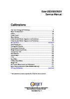
Maximum relative humidi‐ ty of inlet air
see figure 1
see figure 1
see figure 1
Weight [kg] Tab. 4
2.4
Tab. 5
2.5
Machine weight
Temperature
Temperature
Ambient Conditions
* Higher elevation permissible only after consultation with the manufacturer Tab. 6
4
Ambient Conditions
Service Manual Screw Compressor CSD
9_5700 10 E
Fig. 1
2
Technical Specification
2.6
Ventilation
Maximum relative humidity T H
2.6
Inlet air temperature [°C] Maximum relative humidity of inlet air [%]
Ventilation The values given are minimum guide values. CSD 82
CSD 102
CSD 122
1.2/0.2*
1.4/0.2*
1.7/0.3*
16500 2500*
20000 3000*
24000 3500*
700 x 700
700 x 700
700 x 700
CSD 82
CSD 102
CSD 122
8
10
10
10
11
14
14
14
15
16
16
16
Inlet aperture Z see fig‐ ure 11 [m2] Forced ventilation with ex‐ haust fan: Flow rate [m3/h] at 100 Pa Exhaust duct: Dimensions [mm] * Option K2 Tab. 7
2.7
Ventilation
Pressure Maximum working pressure: see nameplate Pressure relief valve activating pressure at 50 Hz [bar] Maximum working pres‐ sure [bar]
Tab. 8
9_5700 10 E
Pressure relief valve activating pressure (50 Hz)
Service Manual Screw Compressor CSD
5
2
Technical Specification
2.8
Delivery
Pressure relief valve activating pressure at 60 Hz [bar] Maximum working pres‐ sure [bar]
Tab. 9
2.8
CSD 82
CSD 102
CSD 122
8.5
10
10
10
12
14
14
14
15
16
16
16
CSD 82
CSD 102
CSD 122
8
8.3
10.1
12.0
11
6.9
8.2
10.0
15
5.4
6.6
8.0
CSD 82
CSD 102
CSD 122
8.5
8.2
9.8
11.8
12
6.6
8.0
9.6
15
5.3
6.4
7.7
Pressure relief valve activating pressure (60Hz)
Delivery Delivery [m3/min] at 50 Hz mains frequency Maximum working pres‐ sure [bar]
Tab. 10
Delivery (50 Hz) Delivery [m3/min] at 60 Hz mains frequency Maximum working pres‐ sure [bar]
Tab. 11
2.9
Delivery (60 Hz)
Cooling Oil Recommendation A sticker showing the type of oil used is located near the oil separator tank filler. Information on ordering cooling oil is found in chapter 11. SIGMA FLUID S–460
MOL
FG–460/FG–680
Description
Silicone-free synthetic oil
Mineral oil
Synthetic oil
Application
Standard oil for all applica‐ Standard oil for all tions except in connection applications except with foodstuffs. in connection with Particularly suitable for ma‐ foodstuffs.
Specifically for applications where the compressed air comes into contact with food‐ stuffs.
chines with a high duty cy‐ Particularly suitable cle. for machines with a low duty cycle.
6
Service Manual Screw Compressor CSD
9_5700 10 E
2
Technical Specification
2.10
Cooling Oil Charge
SIGMA FLUID S–460
MOL
FG–460/FG–680
Approval
—
—
USDA H–1, NSF Approved for the manufac‐ ture of foodstuff packaging, meat and poultry processing and other food processing.
Viscosity at 40 °C
45 mm2/s (D 445; ASTM Test)
44 mm2/s (DIN 51562–1)
50.7/70.0 mm2/s (D 445; ASTM Test)
Viscosity at 100 °C
7.2 mm2/s (D 445; ASTM Test)
6.8 mm2/s (DIN 51562–1)
8.2/710.4 mm2/s (D 445; ASTM Test)
Flash point
238 °C (D 92; ASTM Test)
220 °C (ISO 2592)
245 °C (D 92; ASTM Test)
Density at 15 °C
864 kg/m3 (ISO 12185)
—
—
Pour point
−46 °C (D 97; ASTM Test)
−33 °C (ISO 3016)
—
Demulsibility at 54 °C
40/40/0/10 min (D 1401; ASTM Test)
—
—
Tab. 12
Cooling Oil Recommendation
2.10
Cooling Oil Charge Air-cooling CSD 82
CSD 102
CSD 122
Total charge [l]
36
36
36
Top-up quantity [l] (minimum–maximum)
4
4
4
CSD 82
CSD 102
CSD 122
Total charge excluding heat recovery [l]
39
39
39
Total charge including heat recovery [l] (option W1/W2/W3)
28
28
28
Top-up quantity [l] (minimum–maximum)
4
4
4
Option K1
Tab. 13
Cooling oil charge (option K1) Water-cooling
Option K2
Tab. 14
9_5700 10 E
Cooling oil charge (option K2)
Service Manual Screw Compressor CSD
7
Option W1/W2/W3
2
Technical Specification
2.11
Motors and Power
Heat Recovery The charge of cooling oil for machines with heat recovery is increased by the volume of oil in the heat exchanger and connecting lines.
CSD 82
Option W1
CSD 102
CSD 122
Additional charge volume [l]* * Enter the volume required by your heat recovery system. Tab. 15
Cooling oil charge (option W1)
CSD 82
CSD 102
CSD 122
4
4
4
CSD 82
CSD 102
CSD 122
3
3
3
CSD 82
CSD 102
CSD 122
45
55
75
Rated speed [min-1]
2965 3568*
2965 3568*
2978 3580*
Enclosure protection
IP 55
IP 55
IP 55
Motor bearing greasing in‐ terval [h]
2000
2000
2000
Option W2 Additional charge volume [l] Tab. 16
Cooling oil charge (option W2)
Option W3 Additional charge volume [l] Tab. 17
Cooling oil charge (option W3)
2.11
Motors and Power
2.11.1
Drive motor Rated power [kW]
Grease requirement, each bearing [g]** h = operating hours * 60Hz ** Transfer data from the motor nameplate to the table for reference purposes. Tab. 18
8
Drive motor
Service Manual Screw Compressor CSD
9_5700 10 E
2.11.2
2
Technical Specification
2.12
Sound Pressure Level
Option K1 Fan motor CSD 82
CSD 102
CSD 122
1.1/1.1*
1.1/1.1*
1.5/1.1*
Rated speed [min ]
940 1120*
940 1120*
930 1120*
Enclosure protection
IP 54
IP 54
IP 54
—
—
2000/—*
Rated power [kW] -1
Motor bearing greasing in‐ terval [h] Grease requirement, each bearing [g]** h = operating hours * 60Hz
** Transfer data from the motor nameplate to the table for reference purposes. Tab. 19
2.11.3
Fan motor (option K1)
Option K2 Fan motor CSD 82
CSD 102
CSD 122
0.12/0.17*
0.12/0.17*
0.12/0.17*
Rated speed [min-1]
2500 2700*
2500 2700*
2500 2700*
Enclosure protection
IP 54
IP 54
IP 54
Rated power [kW]
* 60Hz Tab. 20
Fan motor (option K2)
2.12
Sound Pressure Level Operational state ■
Nominal volume flow
■
Nominal pressure
Measurement conditions ■
Free-field measurement to CAGI/PNEUROP PN8 NTC 2.3
■
Measurement distance: 1 m
Sound pressure level [dB(A)]
Tab. 21
9_5700 10 E
CSD 82
CSD 102
CSD 122
at 50 Hz
69
69
71
at 60 Hz
70
70
72
Sound pressure level
Service Manual Screw Compressor CSD
9
2.13
2
Technical Specification
2.13
Power Supply
Power Supply Basic requirements The machine is designed for a power supply conforming to EN 60204–1 (IEC 60204–1), section 4.3. In the absence of other user-specified conditions, the limits laid down in this standard must be adhered to. It is recommended that the supplier and user confer and agree on the basis of the EN 60240–1, Annex B. The machine requires a symmetrical three-phase power supply. In a symmetrical three-phase supply the phase angles and voltages are all the same. The machine may only be operated from an earthed TN or TT three-phase supply. Connection to an IT supply is not permitted without taking further measures (earth leak detection, etc.). Further requirements Demands on a three-phase supply for a machine with the following equipment: ■
Variable frequency drive (SFC)
■
Refrigeration dryer powered from a transformer
This machine may only be supplied from an earthed TN or TT three-phase supply in which the neutral point is earthed. The machine may not be connected to a three-phase supply in which one of the phases is earthed, as this can lead to dangerous voltage surges. Connection to an IT supply is not permitted without further measures being taken (earth leak detection, specially designed frequency converter, etc.). Further information
2.14
The electrical diagram in chapter 13.4 contains further details of the power supply connection.
Power Supply Specifications The following supply cable conductor cross sections (copper multicore) and fusing (slow-blow class gL) are selected according to German DIN VDE 0100–430 (IEC 60364–4–43 and IEC 60364– 4–473) and DIN VDE 0298-4 standards for 30 °C ambient temperature and wiring type C. ➤ The conductor cross-sections should be changed accordingly if other conditions prevail. Other conditions would include:
2.14.1
■
higher temperature
■
other cable laying method
■
cable lengths >50 m
Mains frequency: 50 Hz Rated power supply 200V±10%/3/50Hz
Mains fusing [A]
CSD 82
CSD 102
CSD 122
200
250
—
* Option K2
10
Service Manual Screw Compressor CSD
9_5700 10 E
2
Technical Specification
2.14
Power Supply Specifications
CSD 82
CSD 102
CSD 122
4x95
4x150
—
177/173*
216/212*
—/—*
CSD 82
CSD 102
CSD 122
Mains fusing [A]
200
224
—
Supply cable [mm2]
4x95
4x120
—
154/151*
189/185*
—/—*
CSD 82
CSD 102
CSD 122
Mains fusing [A]
100
125
160
Supply cable [mm2]
4x35
4x50
4x70
89/87*
108/107*
139/136*
CSD 82
CSD 102
CSD 122
Mains fusing [A]
200
224
—
Supply cable [mm2]
4x95
4x120
—
160/156*
191/187*
—/—*
CSD 82
CSD 102
CSD 122
Mains fusing [A]
125
160
200
Supply cable [mm2]
4x50
4x70
4x95
99/97*
114/112*
148/145*
Supply cable [mm ] 2
Current drawn [A] * Option K2 Tab. 22
Connection details 200V/3/50Hz Rated power supply: 230V±10%/3/50Hz
Current drawn [A] * Option K2 Tab. 23
Connection details 230V/3/50Hz Rated power supply: 400V±10%/3/50Hz
Current drawn [A] * Option K2 Tab. 24
2.14.2
Connection details 400V/3/50Hz
Mains frequency: 60 Hz Rated power supply: 230V±10%/3/60Hz
Current drawn [A] * Option K2 Tab. 25
Connection details 230V/3/60Hz Rated power supply: 380V±10%/3/60Hz
Current drawn [A] * Option K2 Tab. 26
9_5700 10 E
Connection details 380V/3/60Hz
Service Manual Screw Compressor CSD
11
2
Technical Specification
2.15
Water-cooling
Rated power supply: 440V±10%/3/60Hz CSD 82
CSD 102
CSD 122
Mains fusing [A]
100
125
160
Supply cable [mm2]
4x35
4x50
4x70
84/82*
102/100*
124/122*
CSD 82
CSD 102
CSD 122
100
125
160
4x35
4x50
4x70
80/79*
97/95*
119/117*
Current drawn [A] * Option K2 Tab. 27
Connection details 440V/3/60Hz Rated power supply: 460V±10%/3/60Hz
Mains fusing [A] Supply cable [mm ] 2
Current drawn [A] * Option K2 Tab. 28
Connection details 460V/3/60Hz
2.15
Option K2 Water-cooling
Further information
2.15.1
The dimensional drawing in chapter 13.3 gives the flow direction, size and position of the connection ports.
Design data Cooling water temperature rise 10 K
Tab. 29
CSD 82
CSD 102
CSD 122
Max. permissible inlet temperature [ °C]
40
40
40
Water flow rate [m3/h]
4.4
5.4
6.3
Pressure drop [bar]
1.2
1.7
2.4
CSD 82
CSD 102
CSD 122
Max. permissible inlet temperature [ °C]
20
20
20
Water flow rate [m3/h]
1.5
1.8
2.1
Pressure drop [bar]
0.5
0.5
0.5
Cooling water temperature (ΔT=10K) Cooling water temperature rise 30 K
Tab. 30
12
Cooling water temperature (ΔT=30K)
Service Manual Screw Compressor CSD
9_5700 10 E
2
Technical Specification
2.15
Water-cooling
Cooler specification CSD 82
CSD 102
CSD 122
1.4401
1.4401
1.4401
Copper (Cu)
Copper (Cu)
Copper (Cu)
Maximum working pres‐ sure [bar] (cooling water)
10
10
10
Max. permissible dis‐ charge temp. [ °C]
70
70
70
Material Braze
Unsuitable cooling medi‐ um Tab. 31
2.15.2
Seawater Consult KAESER on the suitability of water.
Cooler specification (option K2)
Cooling water quality Oil may contaminate the cooling water if a leak occurs. ➤ A special heat exchanger must be used for heating drinking water. The specific heat capacity and required flow rate of the cooling water changes if antifreeze is added. ➤ Consult KAESER Service to ensure optimum cooling-system performance. It is imperative that measures for cooling water treatment and filtration are implemented. KAESER can provide the names of companies specializing in cooling water analysis and the supply of suitable treatment plant. Characteristics/content
Value
pH value
7,5–9
Hardness [°dH] Chloride (Cl) [mg/l]