Range Rover Workshop Manual 2007-2010 PDF [PDF]
CONTENTS 1: General Information 100: Service Information 100-00: General Information Description and Operation About Thi
54 1 72MB
Papiere empfehlen


![Range Rover Workshop Manual 2007-2010 PDF [PDF]](https://vdoc.tips/img/200x200/range-rover-workshop-manual-2007-2010-pdf.jpg)
- Author / Uploaded
- Dr. Stan Wardel BA, MA, MChem, MBA, DPhil, DSc.
Datei wird geladen, bitte warten...
Zitiervorschau
CONTENTS 1: General Information 100: Service Information 100-00: General Information Description and Operation About This Manual How To Use This Manual Important Safety Instructions Standard Workshop Practices General Service Information Health and Safety Precautions Solvents, Sealants and Adhesives Special Tool Glossary Road/Roller Testing DTC: Module Name: Bluetooth Module 100-01: Identification Codes Description and Operation Identification Codes 100-02: Jacking and Lifting Description and Operation Jacking Lifting Vehicle Recovery 100-03: Maintenance Schedules Description and Operation Maintenance Schedules - Gasoline Engines Maintenance Schedules - Diesel Engines 2: Chassis 204: Suspension 204-00: Suspension System - General Information Specification General Procedures Front Camber, Caster and Toe Adjustment Four-Wheel Alignment (57.65.04) 204-01: Front Suspension Specification Description and Operation Front Suspension Removal and Installation Front Lower Arm (60.35.02) (60.35.03) Front Lower Arm Bushing (60.35.26) Front Shock Absorber (60.30.02) Front Stabilizer Bar (60.10.01) Front Stabilizer Bar Link (60.10.02/60.10.04) Rear Lower Arm (60.40.09) Rear Lower Arm Ball Joint (60.15.04)
Rear Lower Arm Bushing (60.35.26) Shock Absorber and Spring Assembly (60.30.25/99) Front Wheel Bearing and Wheel Hub (60.25.14) Wheel Knuckle (60.25.01) Disassembly and Assembly Shock Absorber and Spring Assembly 204-02: Rear Suspension Specification Description and Operation Rear Suspension Removal and Installation Lower Arm (64.35.54) Lower Arm Ball Joint (64.15.08) Lower Arm Bushing (64.35.15) Lower Arm Rear Bushing (64.35.15) Rear Stabilizer Bar (64.35.08) Rear Stabilizer Bar Link (64.35.24) Toe Link (64.35.70) Upper Arm (64.35.60) - TDV8 3.6L Diesel Upper Arm (64.35.60) - 4.4L NA V8 - AJ41/4.2L SC V8 - AJV8 Upper Arm Ball Joint (64.15.07) Upper Arm Bushing (64.35.22) - TDV8 3.6L Diesel Upper Arm Bushing (64.35.22) - 4.4L NA V8 - AJ41/4.2L SC V8 - AJV8 Upper Arm Front Bushing (64.35.20) Upper Arm Rear Bushing (64.35.21) Wheel Bearing and Wheel Hub (64.15.14) Wheel Knuckle (64.35.10) 204-04: Wheels and Tires Description and Operation Wheels and Tires Diagnosis and Testing Wheels and Tires Tire Pressure Monitoring System (TPMS) Removal and Installation Tire Low Pressure Sensor (74.10.05) Tire Pressure Monitoring System (TPMS) Front Antenna (86.53.16) Tire Pressure Monitoring System (TPMS) Module (86.54.05) Tire Pressure Monitoring System (TPMS) Rear Antenna (86.53.17) Wheel and Tire (60.25.06) 204-05: Vehicle Dynamic Suspension Specification Description and Operation Vehicle Dynamic Suspension General Procedures Air Suspension System Depressurize and Pressurize (60.50.38) Ride Height Adjustments (60.90.03) Removal and Installation Air Spring Solenoid Valve Air Suspension Air Filter (64.50.12)
Air Suspension Compressor (60.50.10) Air Suspension Compressor Drier (60.50.09) Air Suspension Control Module (60.50.04) Air Suspension Front Solenoid Valve Block (60.50.11) Air Suspension Muffler (64.50.01) Air Suspension Rear Solenoid Valve Block (64.50.11) Air Suspension Reservoir (60.50.03) Air Suspension Reservoir Solenoid Valve Block (60.50.05) Air Suspension Solenoid Valve Block (60.50.11) Air Suspension Switch Fill Solenoid Valve Front Air Shock Absorber (60.30.02.45) Front Air Spring (60.21.01) Front Vertical Accelerometer Rear Air Shock Absorber (64.30.02.45) Rear Air Spring (64.21.01) Suspension Height Sensor (60.36.01) 204-06: Ride and Handling Optimization Specification Description and Operation Ride and Handling Optimization Diagnosis and Testing Ride and Handling Optimization Removal and Installation Ride and Handling Optimization Switch (86.65.11) 205: Driveline 205-00: Driveline System - General Information Specification 205-01: Driveshaft Specification Description and Operation Driveshaft Universal Joints Removal and Installation Front Driveshaft (47.15.02) - 4.4L NA V8 - AJ41/4.2L SC V8 - AJV8 Front Driveshaft (47.15.02) - TDV8 3.6L Diesel Rear Driveshaft (47.15.03) - 4.4L NA V8 - AJ41/4.2L SC V8 - AJV8 Rear Driveshaft (47.15.03) - TDV8 3.6L Diesel Disassembly and Assembly Driveshaft Universal Joint (47.15.06) Driveshaft Center Bearing Driveshaft Slip Yoke Driveshaft Alignment Bushing 205-02: Rear Drive Axle/Differential Specification Description and Operation Rear Drive Axle and Differential General Procedures Differential Draining and Filling (51.25.02)
In-Vehicle Repair Axle Housing Bushing (51.15.43) - 4.4L NA V8 - AJ41/4.2L SC V8 AJV8 Axle Housing Bushing (51.15.43) - TDV8 3.6L Diesel Axle Shaft Seal Differential Locking Module (51.30.01) Differential Locking Motor (51.15.03) Drive Pinion Seal (51.20.01) Rear Axle Oil Temperature Sensor (51.15.06) Removal and Installation Axle Assembly (51.15.01) Differential Support Insulator - 4.4L NA V8 - AJ41/4.2L SC V8 - AJV8 205-03: Front Drive Axle/Differential Specification Description and Operation Front Drive Axle and Differential General Procedures Differential Draining and Filling (54.15.02) In-Vehicle Repair Drive Pinion Seal (54.10.20) Removal and Installation Differential Breather Tube 205-04: Front Drive Halfshafts Specification Description and Operation Front Drive Halfshafts Halfshaft Joint Removal and Installation Front Halfshaft LH (47.10.01) Front Halfshaft RH (47.10.02) Halfshaft Bearing (47.10.41) Halfshaft Seal LH (54.10.18) Halfshaft Seal RH (54.10.21) 205-05: Rear Drive Halfshafts Specification Description and Operation Rear Drive Halfshafts Removal and Installation Rear Halfshaft (47.11.01) Outer Constant Velocity (CV) Joint Boot (47.11.03) Inner Constant Velocity (CV) Joint Boot (47.11.16) Halfshaft Bearing (51.10.29) 206: Brake System 206-00: Brake System - General Information Specification General Procedures Front Brake Disc Runout Check (70.12.15.01) Rear Brake Disc Runout Check (70.12.36.01) Brake System Bleeding (70.25.02) - Vehicles With: High Performance Brakes
Brake System Bleeding (70.25.02) - Vehicles With: Standard Brakes Brake System Pressure Bleeding (70.25.02) Component Bleeding - Vehicles With: High Performance Brakes Component Bleeding - Vehicles With: Standard Brakes 206-03: Front Disc Brake Specification Description and Operation Front Disc Brake Removal and Installation Brake Disc (70.12.10) - Vehicles With: Standard Brakes Brake Disc (70.12.10) - Vehicles With: High Performance Brakes Brake Pads (70.40.02) - Vehicles With: Standard Brakes Brake Pads (70.40.02) - Vehicles With: High Performance Brakes Brake Caliper (70.55.24) - Vehicles With: Standard Brakes Brake Caliper (70.55.24) - Vehicles With: High Performance Brakes 206-04: Rear Disc Brake Specification Description and Operation Rear Disc Brake Removal and Installation Brake Disc (70.12.33) Brake Pads (70.40.03) Brake Caliper (70.55.25) Disassembly and Assembly Brake Caliper 206-05: Parking Brake and Actuation Specification Description and Operation Parking Brake General Procedures Parking Brake Shoe and Lining Adjustment (70.40.11) Parking Brake Shoes Bedding-In (70.40.12) Removal and Installation Parking Brake Actuator (70.35.48) Parking Brake Cable LH Parking Brake Cable RH Parking Brake Shoes (70.40.09) Parking Brake Switch (70.35.46) 206-06: Hydraulic Brake Actuation Description and Operation Hydraulic Brake Actuation Removal and Installation Brake Fluid Reservoir (70.25.31) - Vehicles With: Standard Brakes Brake Fluid Reservoir (70.25.31) - Vehicles With: High Performance Brakes Brake Master Cylinder (70.30.08) - Vehicles With: Standard Brakes Brake Master Cylinder (70.30.08) - Vehicles With: High Performance Brakes Brake Pedal (70.35.01) - Vehicles With: 6-Speed Automatic Transmission - 6HP26
Brake Pedal and Bracket (70.35.03) - Vehicles With: 6-Speed Automatic Transmission - 6HP26 Brake Pedal Motor 206-07: Power Brake Actuation Specification Description and Operation Brake Booster Removal and Installation Brake Booster (70.50.01) - Vehicles With: Standard Brakes Brake Booster (70.50.01) - Vehicles With: High Performance Brakes Brake Vacuum Pump (70.50.19) - 4.4L NA V8 - AJ41/4.2L SC V8 - AJV8 206-09A: Anti-Lock Control - Traction Control Specification Description and Operation Anti-Lock Control - Traction Control Diagnosis and Testing Anti-Lock Control - Traction Control - VIN Range: 263535->ONWARDS Removal and Installation Anti-Lock Brake System (ABS) Module (70.25.12) - Vehicles With: Standard Brakes Anti-Lock Brake System (ABS) Module (70.25.12) - Vehicles With: High Performance Brakes Front Wheel Speed Sensor (70.65.30) Rear Wheel Speed Sensor (70.65.31) 206-09B: Anti-Lock Control - Stability Assist Specification Removal and Installation Yaw Rate Sensor (70.70.35) 211: Steering System 211-00: Steering System - General Information Specification General Procedures Power Steering System Filling and Bleeding Power Steering System Flushing 211-02: Power Steering Specification Description and Operation Power Steering General Procedures Removal and Installation Power Steering Control Valve Actuator (57.10.05) Power Steering Fluid Cooler (57.15.11) - 4.2L SC V8 - AJV8 Power Steering Pump (57.20.14) - 4.2L SC V8 - AJV8 Steering Angle Sensor (57.40.02) 211-03: Steering Linkage Specification Removal and Installation Steering Gear Boot (57.10.29) Tie Rod End (57.55.07) - 3-Door Tie Rod End (57.55.07)
211-04: Steering Column Specification Description and Operation Steering Column Removal and Installation Ignition Switch Lock Cylinder Steering Column (57.40.01) (57.40.06) Steering Column Shaft (57.40.22) Steering Column Tilt Motor Steering Column Telescopic Motor Steering Wheel (57.61.01) Tilt/Telescopic Motors 211-05: Steering Column Switches Specification Removal and Installation Hazard Flasher Switch (86.65.50) Ignition Switch (86.65.02) Steering Column Control Switch Steering Column Multifunction Switch LH (86.65.55) 3: Powertrain 303: Engine 303-00: Engine System - General Information Specification Diagnosis and Testing Engine (12.90.09.01) - 4.4L NA V8 - AJ41/4.2L SC V8 - AJV8 General Procedures Bearing Inspection Camshaft Bearing Journal Clearance Camshaft Bearing Journal Diameter Camshaft End Play Camshaft Lobe Lift Camshaft Surface Inspection Connecting Rod Cleaning Connecting Rod Large End Bore Crankshaft End Play Crankshaft Main Bearing Journal Clearance Cylinder Bore Out-of-Round Cylinder Head Distortion Exhaust Manifold Cleaning and Inspection Piston Inspection Piston Pin Diameter Piston Pin to Bore Diameter Piston Ring End Gap Piston Ring-to-Groove Clearance Valve Spring Free Length Valve Stem Diameter 303-01A: Engine - 4.2L SC V8 - AJV8 Specification Description and Operation
Engine General Procedures Valve Clearance Check (12.29.73) Valve Clearance Adjustment (12.29.76) Engine Oil Draining and Filling (12.60.05) In-Vehicle Repair Camshafts RH (12.13.20) Camshafts LH (12.13.21) Crankshaft Pulley (12.21.01) Crankshaft Front Seal (12.21.14) Crankshaft Rear Seal (12.21.20) Cylinder Head LH (12.29.04) Timing Drive Components (12.65.13) Valve Cover LH (12.29.43) Valve Cover RH (12.29.44) Engine Mount LH (12.45.11) Engine Mount RH (12.45.12) Flexplate (12.53.13) Oil Level Indicator and Tube (12.60.09) Auxiliary Oil Cooler Thermostat (12.60.17) Oil Pump (12.60.26) Oil Filter Housing (12.60.27) Oil Pan (12.60.44) Oil Cooler (12.60.68) Engine Front Cover (12.65.01) Exhaust Manifold LH (30.15.10) Exhaust Manifold RH (30.15.11) Auxiliary Oil Cooler Removal and Installation Crankshaft Main Bearing Carrier (12.21.42) Removal Engine (12.41.01.99) Disassembly Engine Assembly Engine Installation Engine (12.41.01.99) 303-03A: Engine Cooling - 4.2L SC V8 - AJV8 Specification Description and Operation Engine Cooling General Procedures Cooling System Draining, Filling and Bleeding (26.10.01) Cooling System Pressure Test Removal and Installation Coolant Expansion Tank (26.15.01) Cooling Fan (26.25.19) Radiator (26.40.01)
Thermostat (26.45.01) Coolant Pump (26.50.01) Coolant Manifold (26.30.64) 303-03D: Supercharger Cooling Specification Description and Operation Supercharger Cooling General Procedures Supercharger Cooling System Draining, Filling and Bleeding (19.46.01) Removal and Installation Coolant Pump (26.50.26) Radiator (26.40.10) Intercooler Hose 303-04A: Fuel Charging and Controls - 4.2L SC V8 - AJV8 Specification Description and Operation Fuel Charging and Controls Removal and Installation Fuel Rail (19.60.04) Fuel Injector (19.60.10) Throttle Body Gasket 303-04D: Fuel Charging and Controls - Turbocharger Description and Operation Turbocharger Diagnosis and Testing Turbocharger Removal and Installation Turbocharger LH Turbocharger RH Turbocharger Actuator Rod 303-05A: Accessory Drive - 4.2L SC V8 - AJV8 Specification Description and Operation Accessory Drive Removal and Installation Cooling Fan Belt (26.25.01) Cooling Fan Belt Tensioner (26.25.02) Accessory Drive Belt (86.10.03) Accessory Drive Belt Tensioner (86.10.06) Accessory Drive Belt Idler Pulley (86.10.23) 303-06A: Starting System - 4.2L SC V8 - AJV8 Specification Description and Operation Starting System Removal and Installation Starter Motor (86.60.01) 303-07A: Engine Ignition - 4.2L SC V8 - AJV8 Specification Description and Operation
Engine Ignition Removal and Installation Spark Plugs (18.20.02) Ignition Coil-On-Plug (18.20.44) 303-07C: Glow Plug System Specification Description and Operation Glow Plug System Diagnosis and Testing Glow Plug System Removal and Installation Glow Plugs (19.60.31) 303-08B: Engine Emission Control - 4.2L SC V8 - AJV8 Description and Operation Engine Emission Control 303-12A: Intake Air Distribution and Filtering - 4.2L SC V8 - AJV8 Specification Description and Operation Intake Air Distribution and Filtering Removal and Installation Air Cleaner (19.10.01) Air Cleaner Element (19.10.10) Supercharger (19.46.15) Supercharger Outlet Pipe (19.46.16) Intake Air Resonator (19.70.03) Charge Air Cooler LH (19.46.19) Charge Air Cooler RH (19.46.18) Throttle Body Elbow (19.22.43) 303-13A: Evaporative Emissions - 4.2L SC V8 - AJV8 Specification Description and Operation Evaporative Emissions General Procedures Evaporative Emission System Leak Test (17.90.02.01) Removal and Installation Evaporative Emission Canister Purge Valve (17.15.39) Evaporative Emission Canister Vent Solenoid Evaporative Emission Canister (17.15.13) 303-14A: Electronic Engine Controls - 4.2L SC V8 - AJV8 Specification Description and Operation Electronic Engine Controls Diagnosis and Testing Electronic Engine Controls General Procedures Powertrain Control Module (PCM) Long Drive Cycle Self-Test Powertrain Control Module (PCM) Short Drive Cycle Self-Test Removal and Installation Engine Oil Pressure (EOP) Sensor (12.60.50)
Oil Temperature Sensor (12.60.65) Engine Coolant Temperature (ECT) Sensor (18.30.10) Crankshaft Position (CKP) Sensor (18.30.12) Throttle Position (TP) Sensor (18.30.17) Camshaft Position (CMP) Sensor LH (18.30.25) Camshaft Position (CMP) Sensor RH (18.30.26) Knock Sensor (KS) (18.30.30) Manifold Absolute Pressure (MAP) Sensor (18.30.56) Fuel Temperature Sensor (19.22.08) Heated Oxygen Sensor (HO2S) LH (19.22.16) Mass Air Flow (MAF) Sensor (19.22.25) Catalyst Monitor Sensor LH (19.22.71) Intake Air Temperature (IAT) Sensor (18.30.09) Fuel Rail Pressure (FRP) Sensor (19.22.29) 307: Automatic Transmission/Transaxle 307-01A: Automatic Transmission/Transaxle - 4.2L SC V8 - AJV8 Specification Description and Operation Automatic Transmission General Procedures Transmission Fluid Drain and Refill (44.24.02) Transmission Fluid Level Check (44.24.06) In-Vehicle Repair Selector Shaft Seal (44.15.34) Transmission Control Module (TCM) (44.15.46) Output Shaft Seal (44.20.21) Fluid Pan, Gasket and Filter (44.24.04) Main Control Valve Body (44.40.01) Transmission Support Insulator (12.45.08) Removal and Installation Transmission (44.20.01) 307-01D: Automatic Transmission/Transaxle - 3.6L V8 - TdV8/4.4L NA V8 - AJ41/4.2L SC V8 - AJV8 Removal and Installation Input Shaft Seal 307-02A: Transmission/Transaxle Cooling - 4.2L SC V8 - AJV8 Description and Operation Transmission Cooling Removal and Installation Transmission Fluid Cooler (44.24.10) 307-05A: Automatic Transmission/Transaxle External Controls - 4.2L SC V8 - AJV8 Specification Description and Operation External Controls General Procedures Selector Lever Cable Adjustment (44.30.04) 308: Manual Transmission/Transaxle, Clutch and Transfer Case 308-07A: Four-Wheel Drive Systems Specification Description and Operation
Four-Wheel Drive Systems - 3.6L (TdV8) Diesel Four-Wheel Drive Systems - 4.2L/4.4L Removal and Installation Transfer Case Shift Motor (41.30.03) High/Low Range Sensor (41.30.07) Transfer Case Clutch Solenoid (41.30.08) 308-07B: Transfer Case Specification Description and Operation Transfer Case General Procedures Transfer Case Draining and Filling (41.20.04) In-Vehicle Repair Transfer Case Input Shaft Seal (41.20.50) - 4.2L SC V8 - AJV8 Transfer Case Front Output Shaft Seal (41.20.51) - 4.2L SC V8 - AJV8 Transfer Case Rear Output Shaft Seal (41.20.54) - 4.2L SC V8 - AJV8 Removal Transfer Case (41.20.25.99) - 4.2L SC V8 - AJV8 Installation Transfer Case (41.20.25) - 4.2L SC V8 - AJV8 309: Exhaust System 309-00A: Exhaust System - 4.2L SC V8 - AJV8 Specification Description and Operation Exhaust System Removal and Installation Catalytic Converter LH (17.50.03) Catalytic Converter RH (17.50.04) Exhaust System (30.10.08) Tailpipe (30.10.22) 310: Fuel System 310-00: Fuel System - General Information Specification General Procedures Diesel Filter Water Drain-Off Fuel System Pressure Release (19.50.02) - 4.2L SC V8 - AJV8 Fuel System Pressure Check (19.50.13) - 4.4L NA V8 - AJ41/4.2L SC V8 - AJV8 Fuel Tank Draining (19.55.02) 310-01A: Fuel Tank and Lines - 4.2L SC V8 - AJV8 Specification Description and Operation Fuel Tank and Lines Removal and Installation Fuel Pump Module (19.45.03) Fuel Tank Filler Pipe (19.55.07) Vapor Vent Box Fuel Tank (19.55.01) Fuel Filter (19.25.03) 310-02A: Acceleration Control - 4.2L SC V8 - AJV8
Description and Operation Acceleration Control 303-01C: Engine - TDV8 3.6L Diesel Specification Description and Operation Engine Diagnosis and Testing Engine General Procedures Engine Oil Draining and Filling (12.60.05) In-Vehicle Repair Camshaft LH (12.13.02) Camshaft RH (12.13.03) Crankshaft Front Seal (12.21.14) Crankshaft Pulley (12.21.01) Crankshaft Rear Seal (12.21.20) Cylinder Head LH (12.29.04) Cylinder Head RH (12.29.05) Engine Mount LH (12.45.11) Engine Mount RH (12.45.12) Exhaust Manifold LH (30.15.10) Exhaust Manifold RH (30.15.11) Flexplate (12.53.13) Intake Manifold Plenum Chamber Oil Pan (12.60.44) Oil Pump (12.60.26) Timing Drive Components (12.65.13) Valve Cover LH (12.29.43) Valve Cover RH (12.29.44) Removal Engine (12.41.01.99) Disassembly Engine Assembly Engine Installation Engine (12.41.01.99) 303-03C: Engine Cooling - TDV8 3.6L Diesel Specification Description and Operation Engine Cooling Diagnosis and Testing Engine Cooling General Procedures Cooling System Partial Draining, Filling and Bleeding Cooling System Partial Draining and Vacuum Filling Cooling System Pressure Test Removal and Installation Auxiliary Radiator Coolant Expansion Tank (26.15.01) Cooling Fan (26.25.19) Cooling Fan Shroud (26.25.11) Cooling Module Coolant Pump (26.50.01) Radiator (26.40.01)
Thermostat (26.45.01) 303-03D: Supercharger Cooling Specification Description and Operation Supercharger Cooling General Procedures Supercharger Cooling System Draining, Filling and Bleeding (19.46.01) Removal and Installation Coolant Pump (26.50.26) Radiator (26.40.10) Intercooler Hose 303-04C: Fuel Charging and Controls - TDV8 3.6L Diesel Specification Description and Operation Fuel Charging and Controls Diagnosis and Testing Fuel Charging and Controls General Procedures Fuel Injection Component Cleaning Fuel Injector Balance and Spill Check (19.90.08) Removal and Installation Fuel Injectors LH Fuel Injectors RH Fuel Pump (19.45.08) Fuel Rail LH Fuel Rail RH Throttle Body (19.22.44) 303-04D: Fuel Charging and Controls - Turbocharger Description and Operation Turbocharger Diagnosis and Testing Turbocharger Removal and Installation Turbocharger LH Turbocharger RH Turbocharger Actuator Rod 303-05C: Accessory Drive - TDV8 3.6L Diesel Specification Description and Operation Accessory Drive Diagnosis and Testing Accessory Drive Removal and Installation Accessory Drive Belt (86.10.03) Accessory Drive Belt Tensioner (86.10.06) Accessory Drive Belt Idler Pulley (86.10.23) 303-06C: Starting System - TDV8 3.6L Diesel Specification Description and Operation Starting System Diagnosis and Testing Starting System Removal and Installation Starter Motor (86.60.01) 303-07C: Glow Plug System
Specification Description and Operation Glow Plug System Diagnosis and Testing Glow Plug System Removal and Installation Glow Plugs (19.60.31) 303-08A: Engine Emission Control - TDV8 3.6L Diesel Specification Description and Operation Engine Emission Control Diagnosis and Testing Engine Emission Control Removal and Installation Crankcase Vent Oil Separator (17.10.04) Exhaust Gas Recirculation (EGR) Cooler (17.45.38) Exhaust Gas Recirculation (EGR) Valve LH (17.45.16) Exhaust Gas Recirculation (EGR) Valve RH (17.45.17) Exhaust Gas Recirculation (EGR) Valve Outlet Tube (17.45.18) 303-12C: Intake Air Distribution and Filtering - TDV8 3.6L Diesel Description and Operation Intake Air Distribution and Filtering Diagnosis and Testing Intake Air Distribution and Filtering Removal and Installation Air Cleaner (19.10.01) Air Cleaner Element (19.10.10) Charge Air Cooler (19.46.19) 303-14C: Electronic Engine Controls - TDV8 3.6L Diesel Specification Description and Operation Electronic Engine Controls Diagnosis and Testing Electronic Engine Controls - 3.6L (TdV8) Diesel Removal and Installation Camshaft Position (CMP) Sensor (18.30.24) Crankshaft Position (CKP) Sensor (18.30.12) Crankshaft Position (CKP) Sensor Ring (18.30.14) Engine Control Module (ECM) (18.30.03) Engine Coolant Temperature (ECT) Sensor (18.30.10) Engine Oil Pressure (EOP) Sensor (12.60.50) Exhaust Gas Temperature Sensor Fuel Rail Pressure (FRP) Sensor (19.22.29) Fuel Temperature Sensor (19.22.08) Knock Sensor (KS) LH (18.30.28) Knock Sensor (KS) RH (18.30.30) Manifold Absolute Pressure and Temperature (MAPT) Sensor Mass Air Flow (MAF) Sensor (19.22.25) 307: Automatic Transmission/Transaxle 307-01C: Automatic Transmission/Transaxle - TDV8 3.6L Diesel Specification Description and Operation Automatic Transmission General Procedures Transmission Fluid Drain and Refill (44.24.02)
Transmission Fluid Level Check (44.24.06) In-Vehicle Repair Fluid Pan, Gasket and Filter (44.24.04) Main Control Valve Body (44.40.01) Output Shaft Seal (44.20.21) Selector Shaft Seal (44.15.34) Transmission Control Module (TCM) (44.15.46) Transmission Support Insulator (12.45.08) Removal and Installation Transmission (44.20.01) 307-01D: Automatic Transmission/Transaxle - TDV8 3.6L Diesel/V8 4.4L Petrol/V8 S/C 4.2L Petrol Removal and Installation Input Shaft Seal 307-02C: Transmission/Transaxle Cooling - TDV8 3.6L Diesel Specification Description and Operation Transmission Cooling Removal and Installation Transmission Fluid Cooler (44.24.10) 307-05C: Automatic Transmission/Transaxle External Controls - TDV8 3.6L Diesel Specification Description and Operation External Controls General Procedures Selector Lever Cable Adjustment (44.30.04) Removal and Installation Selector Lever Assembly (44.15.04) Selector Lever Cable (44.15.08) Selector Lever Gate Finish Panel Selector Lever Knob (44.15.07) Selector Lever Position Sensor 308: Manual Transmission/Transaxle, Clutch and Transfer Case 308-07A: Four-Wheel Drive Systems Specification Description and Operation Four-Wheel Drive Systems - TDV8 3.6L Diesel Diagnosis and Testing Four-Wheel Drive Systems Removal and Installation Transfer Case Shift Motor (41.30.03) High/Low Range Sensor (41.30.07) Transfer Case Clutch Solenoid (41.30.08) 308-07B: Transfer Case Specification Description and Operation Transfer Case General Procedures Transfer Case Draining and Filling (41.20.04) In-Vehicle Repair Transfer Case Input Shaft Seal (41.20.50) - TDV8 3.6L Diesel Transfer Case Front Output Shaft Seal (41.20.51) - TDV8 3.6L Diesel Transfer Case Rear Output Shaft Seal (41.20.54) - TDV8 3.6L Diesel Removal Transfer Case (41.20.25.99) - TDV8 3.6L Diesel
Installation Transfer Case (41.20.25) - TDV8 3.6L Diesel 309: Exhaust System 309-00C: Exhaust System - TDV8 3.6L Diesel Specification Description and Operation Exhaust System Removal and Installation Catalytic Converter (17.50.01) Catalytic Converter LH (17.50.03) - Vehicles Without: Diesel Particulate Filter (DPF) Catalytic Converter RH (17.50.04) - Vehicles Without: Diesel Particulate Filter (DPF) Catalytic Converter LH (17.50.03) - Vehicles With: Diesel Particulate Filter (DPF) Catalytic Converter RH (17.50.04) - Vehicles With: Diesel Particulate Filter (DPF) Diesel Particulate Filter (DPF) Diesel Particulate Filter (DPF) Differential Pressure Sensor Exhaust System (30.10.08) - Vehicles Without: Diesel Particulate Filter (DPF) Exhaust System (30.10.08) - Vehicles With: Diesel Particulate Filter (DPF) Tailpipe (30.10.22) 310: Fuel System 310-00: Fuel System - General Information Specification General Procedures Diesel Filter Water Drain-Off Fuel System Pressure Check (19.50.13) - TDV8 3.6L Diesel Fuel Tank Draining (19.55.02) High-Pressure Fuel System Bleeding - TDV8 3.6L Diesel Low-Pressure Fuel System Bleeding (19.50.07) - TDV8 3.6L Diesel 310-01C: Fuel Tank and Lines - TDV8 3.6L Diesel Specification Description and Operation Fuel Tank and Lines Diagnosis and Testing Fuel Tank and Lines Removal and Installation Auxiliary Fuel Cooler Fuel Cooler Fuel Filter Element (192502) Fuel Tank (19.55.01) Fuel Tank Filler Pipe (19.55.07) 310-02C: Acceleration Control - TDV8 3.6L Diesel Specification Description and Operation Acceleration Control Removal and Installation Accelerator Pedal (19.20.01) 310-03B: Speed Control - TDV8 3.6L Diesel Description and Operation Speed Control Removal and Installation Speed Control Switch
4: Electrical 412: Climate Control System 412-00: Climate Control System - General Information Specification General Procedures Air Conditioning (A/C) System Recovery, Evacuation and Charging (82.30.02) 412-01: Air Distribution and Filtering Specification Description and Operation Air Distribution and Filtering Removal and Installation Center Registers Driver Side Register Driver Side Register Trim Panel (76.46.12) Passenger Side Register Passenger Side Register Trim Panel (76.46.13) Plenum Chamber (80.15.62) Upper Center Registers 412-02A: Heating and Ventilation Specification Description and Operation Heating and Ventilation Removal and Installation Blower Motor (80.20.15) Heater Control Valve Heater Core (80.20.29) Heater Core and Evaporator Core Housing 412-02B: Auxiliary Heating Specification Description and Operation Auxiliary Heater Removal and Installation Auxiliary Heater Fuel Fired Booster Heater - 4.2L SC V8 - AJV8 412-03A: Air Conditioning Specification Description and Operation Air Conditioning Removal and Installation Air Conditioning (A/C) Compressor (82.10.20) - 4.2L SC V8 - AJV8 Condenser Core (82.15.07) - 4.2L SC V8 - AJV8 Condenser Fan - 4.2L SC V8 - AJV8 Evaporator Core (82.25.20) (82.25.22) Thermostatic Expansion Valve (82.25.01) Air Conditioning (A/C) Compressor (82.10.20) - TDV8 3.6L Diesel Condenser Core (82.15.07) - TDV8 3.6L Diesel Condenser Fan - TDV8 3.6L Diesel Evaporator Core (82.25.20) (82.25.22)
Receiver Drier (82.17.03) - TDV8 3.6L Diesel Thermostatic Expansion Valve (82.25.01) 412-03B: Auxiliary Climate Control Specification Description and Operation Auxiliary Climate Control Removal and Installation Auxiliary Climate Control Assembly (82.26.22) Auxiliary Evaporator Outlet and Inlet Line Auxiliary Footwell Vent/Duct Blend Door Actuator Auxiliary Heater Core and Evaporator Core Housing Auxiliary Temperature Blend Door Actuator (82.26.34) Auxiliary Blower Motor (82.26.33) Auxiliary Blower Motor Resistor Evaporator Core (82.26.20) Heater Core (82.26.19) Register 412-04: Control Components Description and Operation Control Components Removal and Installation Ambient Air Temperature Sensor (80.40.31) Climate Control Assembly (80.10.02) Defrost Vent/Register Blend Door Actuator (80.10.36) Driver Side Recirculation Blend Door Actuator Driver Side Temperature Blend Door Actuator (80.10.37) Footwell Vent/Duct Blend Door Actuator Instrument Panel Blend Door Actuator (80.20.09) In-Vehicle Temperature Sensor (82.20.93) Passenger Side Recirculation Blend Door Actuator Passenger Side Temperature Blend Door Actuator (80.10.38) Sunload Sensor (82.20.92) 413: Instrumentation and Warning Systems 413-00: Instrument Cluster and Panel Illumination Specification Description and Operation Instrument Cluster and Panel Illumination 413-01: Instrument Cluster Specification Description and Operation Instrument Cluster Removal and Installation Instrument Cluster (80.20.01.99) (88.20.01) 413-06: Horn Specification Removal and Installation Horn (86.30.09) Horn Switch (86.30.01) 413-07: Clock
Removal and Installation Clock (88.15.07) 413-08: Information and Message Center Description and Operation Information and Message Center 413-09A: Warning Devices Specification Removal and Installation Low Washer Fluid Warning Indicator Switch 413-09B: Engine Protection System Specification Removal and Installation Engine Protection System Module 413-13: Parking Aid Specification Description and Operation Parking Aid Diagnosis and Testing Parking Aid Removal and Installation Front Inner Parking Aid Sensor (86.54.21) Front Parking Aid Speaker Front Outer Parking Aid Sensor (86.54.22) Parking Aid Camera Parking Aid Module (86.54.10) Rear Parking Aid Sensor Rear Parking Aid Speaker (86.54.19) 414: Battery and Charging System 414-00: Charging System - General Information Specification Description and Operation Charging System General Procedures Battery Charging 414-01: Battery, Mounting and Cables Specification Description and Operation Battery and Cables Removal and Installation Battery (86.15.01) Battery Tray (76.10.30) Auxiliary Battery Tray (76.10.31) 414-02A: Generator and Regulator - 4.2L SC V8 - AJV8 Specification Description and Operation Generator Removal and Installation Generator (86.10.02) 414-02C: Generator and Regulator - TDV8 3.6L Diesel
Specification Description and Operation Generator Removal and Installation Generator (86.10.02) 415: Information and Entertainment Systems 415-00: Information and Entertainment System - General Information Diagnosis and Testing Information and Entertainment System Cellular Phone 415-01A: Audio Unit Specification Description and Operation Audio System Removal and Installation Audio Unit (86.50.81) Audio Unit Amplifier Compact Disc (CD) Changer Integrated Control Panel (ICP) Rear Auxiliary Audio Controls Satellite Radio Tuner Steering Wheel Audio Controls Subwoofer Amplifier Television (TV) Amplifier Television (TV) Amplifier and Fuel Fired Booster Heater Transceiver Unit Television (TV) Receiver 415-01B: Information and Entertainment System Description and Operation Intercom System 415-02: Antenna Specification Description and Operation Antenna Removal and Installation Antenna Antenna Module Power Antenna 415-03: Speakers Specification Description and Operation Speakers Removal and Installation Front Door Speaker (86.50.10) Rear Door Speaker (86.50.12) Instrument Panel Speaker (86.50.11) Quarter Panel Speaker (86.50.48) Tailgate Speaker (86.50.47) 415-07: Video System
Description and Operation Video System Diagnosis and Testing Video System Removal and Installation Digital Versatile Disc (DVD) Player Portable Camera Portable Camera Docking Station Rear Passenger Entertainment Control Panel Video System Module 417: Lighting 417-01: Exterior Lighting Specification Description and Operation Exterior Lighting Diagnosis and Testing Headlamps General Procedures Headlamp Adjustment (86.40.17) Removal and Installation Adaptive Front Lighting Module (86.54.06) Front Fog Lamp (86.40.96) Headlamp Assembly (86.40.49) Headlamp Bulb (86.40.09) Headlamp Switch (86.65.09) High Mounted Stoplamp (86.41.32) Lamp Outage Module License Plate Lamp (86.40.86) Rear Lamp Assembly (86.40.70) Side Turn Signal Lamp (86.40.53) Stoplamp Switch (70.35.42) Trailer Module 417-02: Interior Lighting Description and Operation Interior Lighting Removal and Installation Center Interior Lamp 417-04: Daytime Running Lamps (DRL) Description and Operation Daytime Running Lamps (DRL) 418: Electrical Distribution 418-00: Module Communications Network Specification Description and Operation Communications Network Removal and Installation Central Junction Box (CJB) (86.70.56) Engine Junction Box (EJB) 418-01: Module Configuration
General Procedures Module Configuration 418-02: Wiring Harnesses Specification Description and Operation Wiring Harness General Procedures Wiring Harness Repair Removal and Installation Engine Wiring Harness (86.70.17) - 4.2L SC V8 - AJV8 Tailgate Wiring Harness 419: Electronic Feature Group 419-01A: Anti-Theft - Active Specification Description and Operation Anti-Theft - Active Removal and Installation Anti-Theft Transceiver Module Hood Switch (86.77.20) Inclination Sensor Intrusion Sensor 419-01B: Anti-Theft - Passive Description and Operation Anti-Theft - Passive Removal and Installation Passive Anti-Theft System (PATS) Module (86.77.07) 419-07: Navigation System Description and Operation Navigation System Diagnosis and Testing Navigation System Removal and Installation Navigation System Digital Versatile Disc (DVD) Unit Navigation System Traffic Module 419-08: Cellular Phone Description and Operation Cellular Phone Removal and Installation Cellular Phone Antenna (86.53.11) Microphone Portable Support Electronics (PSE) Module 419-10: Multifunction Electronic Modules Description and Operation Module Controlled Functions Removal and Installation Generic Electronic Module (GEM) Information and Entertainment Module Multifunction Voice Activated Module 5: Body and Paint
501: Body and Paint 501-00: Body System - General Information Specification Description and Operation Body Body Body 501-02: Front End Body Panels Removal and Installation Cowl Panel Grille Engine Undershield (76.10.50) Fender (76.10.24) Fender Splash Shield (76.10.48) Headlamp Mounting Bracket Radiator Grille Support (76.10.12) Radiator Splash Shield (76.11.81) 501-03: Body Closures Description and Operation Body Closures Removal and Installation Door Liftgate Strut Tailgate Strut 501-05: Interior Trim and Ornamentation Specification Removal and Installation A-Pillar Trim Panel (76.13.26) B-Pillar Trim Panel C-Pillar Lower Trim Panel (76.13.34) (76.13.37) C-Pillar Upper Trim Panel (76.13.35) Cowl Side Trim Panel (76.13.27) Engine Cover (12.30.50) - 4.2L SC V8 - AJV8 Front Door Speaker Grille Front Door Trim Panel (76.34.01) Front Scuff Plate Trim Panel (76.49.17) Headliner (76.64.15) Liftgate Lower Trim Panel Liftgate Upper Trim Panel Loadspace Trim Panel Rear Door Trim Panel (76.34.04) Rear Scuff Plate Trim Panel Rear Quarter Trim Panel (76.13.12) Sun Visor Tailgate Trim Panel (76.49.23) 501-08: Exterior Trim and Ornamentation Description and Operation Exterior Trim Exterior Trim Exterior Trim
Diagnosis and Testing Power Side Step Removal and Installation Front Fender Moulding (76.43.54) Front Fender Trim Panel Front Door Lower Moulding Power Side Step Power Side Step Hinge Power Side Step Motor Radiator Grille (76.55.03) Rear Door Lower Moulding Rear Fender Splash Shield (76.10.49) Roof Moulding (76.43.68) Rear Quarter Panel Moulding (76.43.55) Rear Spoiler Rocker Panel Moulding Tailgate Moulding (76.43.99) Towbar 501-09: Rear View Mirrors Specification Description and Operation Rear View Mirrors Removal and Installation Exterior Mirror (76.11.10) Exterior Mirror Glass (76.11.08) Exterior Mirror Motor (76.11.09) Interior Rear View Mirror 501-10: Seating Description and Operation Seats Diagnosis and Testing Seats Removal and Installation Climate Controlled Seat Switch Front Seat (78.10.44/99) Front Seat Backrest Cover (78.90.08) Front Seat Backrest Lower Rear Cover Front Seat Backrest Heater and Blower Assembly Front Seat Cushion Heater and Blower Assembly Front Seat Cushion Cover (78.30.01) Front Seat Head Restraint - Vehicles With: Head Restraint Video Display Front Seat Head Restraint - Vehicles Without: Head Restraint Video Display Front Seat Head Restraint Motor Front Seat Recliner Motor (78.70.34) Lumbar Assembly Lumbar Control Switch Seat Armrest (78.10.01) Seat Control Switch
Rear Seat (78.10.70/78.10.71) Rear Seat Armrest Rear Seat Backrest Cover (78.90.72) Rear Seat Cushion Cover (78.40.70) 501-11: Glass, Frames and Mechanisms Description and Operation Glass, Frames and Mechanisms Diagnosis and Testing Glass, Frames and Mechanisms General Procedures Heated Window Grid Wire Repair Lead Terminal Repair Door Window Glass Adjustment Door Window Glass Adjustment Rear Quarter Window Glass Adjustment Rear Quarter Window Glass Adjustment Liftgate Window Glass Adjustment Power Door Window Initialization Power Door Window Initialization Power Rear Window Initialization Heated Window Grid Wire Repair Lead Terminal Repair Windshield Reseal Door Window Glass and Rear Quarter Window Glass Adjustment Removal and Installation Driver Door Window Control Switch Front Door Window Regulator Motor Front Door Window Glass (76.31.01) Liftgate Window Glass (76.31.22) Rear Door Window Glass (76.31.02) Rear Door Window Regulator Motor Rear Quarter Window Glass (76.81.20) Windshield Glass (76.81.01) Windshield Moulding Rear Door Fixed Window Glass (76.31.31) 501-12: Instrument Panel and Console Description and Operation Instrument Panel Floor Console Overhead Console Removal and Installation Floor Console (76.25.01) Floor Console Cup Holder Floor Console Extension Floor Console Stowage Compartment Floor Console Stowage Compartment Lid Floor Console Upper Panel (76.25.11) In-Vehicle Crossbeam Instrument Panel Center Reinforcement (76.46.34)
Instrument Panel Lower Section (76.46.05) Instrument Panel Reinforcement Instrument Panel Upper Section (76.46.04) Lower Center Registers Panel Assembly Lower Glove Compartment Lower Glove Compartment Lid Overhead Console (76.25.02) Upper Glove Compartment Upper Glove Compartment Lid 501-14: Handles, Locks, Latches and Entry Systems Description and Operation Handles, Locks, Latches and Entry Systems Diagnosis and Testing Locks, Latches and Entry Systems General Procedures Tailgate Striker Adjustment (76.28.03) Liftgate Striker Adjustment (76.37.28) Removal and Installation Exterior Front Door Handle (76.58.07) Exterior Door Handle Mechanism Front Door Latch (76.37.12) Ignition Lock Cylinder (57.40.28) Liftgate Latch (76.37.19) Tailgate Latch (76.37.83) Tailgate Latch Actuator Tailgate Release Switch 501-16: Wipers and Washers Specification Description and Operation Wipers and Washers Removal and Installation Rain Sensor (84.12.11) Rear Window Wiper Motor (84.35.12) Rear Window Wiper Pivot Arm Windshield Washer Pump (84.10.21) Windshield Washer Reservoir (84.10.03) Windshield Wiper Intermittent Wipe Relay Windshield Wiper Motor (84.15.12) Windshield Wiper Pivot Arm Wiper Linkage Assembly 501-17: Roof Opening Panel Description and Operation Roof Opening Panel General Procedures Roof Opening Panel Alignment (76.84.82) Removal and Installation Air Deflector Roof Opening Panel Glass (76.84.03) Lifter Arms
Roof Opening Panel (76.84.01) Roof Opening Panel Motor (76.84.07) Roof Opening Panel Shield 501-19: Bumpers Specification Removal and Installation Front Bumper (76.22.49) Front Bumper Cover (76.22.72) Front Bumper Lower Cover (76.22.78) Rear Bumper (76.22.52) Rear Bumper Cover (76.22.74) 501-20A: Safety Belt System Specification Description and Operation Safety Belt System Removal and Installation Front Safety Belt Buckle (76.73.30) Front Safety Belt Retractor (76.73.13) Rear Center Safety Belt Buckle (76.73.64) Rear Center Safety Belt Retractor Rear Safety Belt Buckle (76.73.30) Rear Safety Belt Retractor 501-20B: Supplemental Restraint System Specification Description and Operation Air Bag and Safety Belt Pretensioner Supplemental Restraint System (SRS) Diagnosis and Testing Air Bag Supplemental Restraint System (SRS) General Procedures Air Bag Disposal Removal and Installation B-Pillar Side Impact Sensor (76.74.23) Clockspring (76.74.20) Driver Air Bag Module (76.74.01) Driver Lower Air Bag Module Front Seat Side Air Bag Module Front Side Air Curtain Module Occupant Classification Sensor (76.74.76) Passenger Air Bag Deactivation (PAD) Switch (76.74.19) Passenger Air Bag Module (76.74.02) Side Air Bag Module (76.74.30) Side Air Curtain Module (76.74.40) 501-25A: Body Repairs - General Information Description and Operation Sealer, Underbody Protection Material and Adhesives 501-25B: Body Repairs - Water Leaks Description and Operation Water Leaks 501-25C: Body Repairs - Corrosion Protection
Description and Operation Corrosion Protection 501-26: Body Repairs - Vehicle Specific Information and Tolerance Checks Description and Operation Body and Frame 501-27: Front End Sheet Metal Repairs Removal and Installation Auxiliary Front Crossmember Fender Apron Panel Fender Apron Panel Closing Panel Fender Apron Panel Front Extension Fender Apron Panel Inner Reinforcement Fender Apron Panel Reinforcement Front Section Fender Apron Panel Reinforcement Rear Section Front Side Member and Suspension Top Mount Assembly Front Side Member Closing Panel Front Side Member Extension Hood Latch Panel (76.16.22) Side Member Deformation Element 501-28: Roof Sheet Metal Repairs Removal and Installation Roof Panel 501-29: Side Panel Sheet Metal Repairs Removal and Installation A-Pillar Assembly A-Pillar Reinforcement B and C-Pillar Assembly Rocker Panel (77.40.60) Rocker Panel Inner Reinforcement Rocker Panel Section 501-30: Rear End Sheet Metal Repairs Removal and Installation Inner Quarter Panel (77.40.37) Quarter Panel (77.40.09) Quarter Panel Lower Extension Rear Crossmember Rear Crossmember Section Rear Floor Panel Rear Floor Panel Section (77.70.02) Rear Lamp Mounting Panel (77.80.25) Rear Quarter Upper Panel Rear Side Member Rear Side Member Section (77.70.07) Spare Wheel Well 501-36: Paint - General Information Description and Operation Tools and Equipment for Paint Repairs 502: Frame and Mounting 502-00: Uni-Body, Subframe and Mounting System
Removal and Installation Rear Subframe Bushing - 4.4L NA V8 - AJ41/4.2L SC V8 - AJV8 502-02: Full Frame and Body Mounting Specification Removal and Installation Transmission Support Crossmember (76.10.09 or 76.10.92) - 4.4L NA V8 - AJ41/4.2L SC V8 - AJV8 Service Bulletins
Fuel Fired Burning Heater Diagnostic's Range Rover (LM) - Drone Noise on Supercharged Vehicles with 20 inch Wheels E-Box Cooling Fan Noise All Land Rover - Special Equipment Release Notification All Land Rover - Electronic Product Quality Report (EPQR) Enhancements All Land Rover - Special Service Tools on EPQR Range Rover (LM) - Sensor Cluster Fault Diagnosis Range Rover (LM) - Internal Control Module Faults Relating to the ABS Module Diagnosis Range Rover (LM) - CAN Faults Relating to the ABS Module Diagnosis Range Rover (LM) - Wheel Speed Sensor Concerns Diagnosis Range Rover (LM) - Storage Location of Front Towing Eye Range Rover (LM) - Spare Key Location Range Rover (LM) - Special Tool Notification Height Sensor Procedure Change
General Information - About This Manual Description and Operation
Introduction This manual has been written in a format that is designed to meet the needs of technicians worldwide. The objective is to use common formats and include similar content in each manual. This manual provides general descriptions for accomplishing diagnosis and testing, service and repair work with tested and effective techniques. Following them will help to ensure reliability.
Important Safety Instructions Appropriate service methods and correct repair procedures are essential for the safe, reliable operation of all motor vehicles as well as the personal safety of the individual carrying out the work. Anyone who departs from the instructions provided in this manual must first establish that personal safety or vehicle integrity is not compromised by the choice of method, tools or components.
Warnings, Cautions and Notes in This Manual
WARNING: Warnings are used to indicate that failure to follow a procedure correctly may result in personal injury.
CAUTION: Cautions are used to indicate that failure to follow a procedure correctly may result in damage to the vehicle or equipment being used. • NOTE: Notes are used to provide additional essential information required to carry out a complete and satisfactory repair. Generic warnings or cautions are in their relevant description and operation procedure within section 100-00. If the generic warnings or cautions are required for a procedure, there will be a referral to the appropriate description and operation procedure. If a warning, caution or note only applies to one step, it is placed at the beginning of the specific step.
Trustmark Authoring Standards (TAS) Removal and Installation Procedures • NOTE: TAS style procedures can be identified by steps that have no accompanying step text and the magenta color of the electrical connectors and fasteners such as nuts, bolts, clamps or clips. A TAS removal and installation procedure uses a sequence of color illustrations to indicate the order to be followed when removing/disassembling or installing/assembling a component. Many of the TAS procedures will have the installation information within the removal steps. These procedures will have the following note at the beginning of the procedure: • NOTE: Removal steps in this procedure may contain installation details. Items such as O-ring seals, gaskets, seals, self-locking nuts and bolts are to be discarded and new components installed unless otherwise stated within the procedure. Coated nuts or bolts are to be reused, unless damaged or otherwise stated within the procedure. Specification procedures will contain all technical data that are not part of a repair procedure. TAS Graphics Colors used in the graphic are as follows:
Blue - Indicates the target item, item to be removed/installed or disassembled/assembled Green and Brown - Indicates a secondary item that needs to be detached, removed/installed or disassembled/assembled prior to the target item Magenta - Indicates electrical connectors and fasteners such as nuts, bolts, clamps or clips Pale Blue - is for the special tool(s) and general equipment.
There may be multiple steps assigned to one illustration. Numbered pointers are used to indicate the number of electrical connectors and fasteners such as nuts, bolts, clamps or clips. Items in the illustration can be transparent or use cutouts to show hidden detail(s).
TAS Symbols Symbols are used inside the graphics and in the text area to enhance the information display. The following paragraphs describe the various types and categories of symbols. Prohibition symbols advise on prohibited actions to either avoid damage or health and safety related risks.
Health and Safety symbols recommend the use of particular protection equipment to avoid or at least reduce the risk or severity of possible injuries.
Warning symbols are used to indicate potential risks resulting from a certain component or area.
Instruction symbols are used to apply sealer, lubricant, weight, tape or cleaning detergent to a component.
Location symbols are used to show the location of a component or system within the vehicle.
Gearshift lever or selector lever position symbols are used to show which gearshift lever or selector lever position is to be set.
Pointer symbols are used to draw the attention to components and give special instructions such as a required sequence or number of components. The number of components is reflected by the value inside the luty arrow. A sequence number is located inside the circle. Numbers inside circles are also used to allocate special information such as tightening torques or chemicals to a particular component.
Movement arrows are used to show three dimensional or rotational movements. These movements can include specific values inside the symbol if required.
Standard tool symbols recommend the use of certain standard tools. These tools can include dimension values if required.
The following graphic illustrates a set of symbols that are used to provide detailed information on where to apply a material.
Measurement symbols provide detailed information on where to carry out a specific measurement. These symbols can include specific values if required.
Special Tools and Torque Figure(s) Special tools will be shown with the tool number in the illustration. The special tool number(s), general equipment, material(s) and torque figure(s) used for the procedure step will be shown in the text column.
General Information - How To Use This Manual Description and Operation
Copyright Statement Copyright.© Land Rover Ltd., 2005 All rights reserved. No part of this publication may be reproduced, stored in a retrieval system or transmitted in any form, electronic, mechanical, photocopying, recording or other means, without prior written permission of Land Rover Ltd., Banbury Road, Lighthorne, Warwick, CV35 0RG
How to use This Manual This manual covers all aspects of 2006 model year updates in order to service the vehicle effectively, and is to be used in conjunction with the existing workshop manual Part number: LRL0477. The manual is structured into five main sections, General Information, Chassis, Powertrain, Electrical and Body and Paint with each section dealing with a specific part of a vehicle system. Each of the five main sections contain sub-sections dealing with items which form a part of that specific system. Pages at the start of the manual list all sections available. Each section has a contents list detailing, where applicable, Specifications, Description and Operation, Diagnosis and Testing, General Procedures and Repair Procedures. Where components need to be removed or disassembled in sequence, each operation in the sequence will be identified numerically and also graphically in an accompanying illustration. • NOTE: Dimensions quoted are to design engineering specifications with service limits quoted, where applicable.
Workshop Manual Organization The five main sections, together with the areas which they cover are given below:
Section Section Section Section Section
1 2 3 4 5
-
General Information. Chassis. Powertrain. Electrical. Body and Paint.
Sub-section numbers appear after the initial section number, for example, Section 412-03 covers air conditioning, which is part of the electrical section. In the number given above, the first digit of the number '4' indicates the section i.e. Electrical. The second and third digits '12' of the number indicate the vehicle system i.e. Air Conditioning. The last two digits of the number '03' indicate the part of the system covered by the sub-section i.e. Air Conditioning Compressor.
General Information - Important Safety Instructions Description and Operation Safety Notice Appropriate service methods and correct repair procedures are essential for the safe, reliable operation of all motor vehicles, as well as the safety of the person doing the work. This manual provides general directions for accomplishing service and repair work with tested effective techniques. Following them will help assure reliability. There are numerous variations in procedures, techniques, tools, and parts for servicing vehicles, as well as in the skill of the person doing the work. This manual cannot possibly anticipate all such variations and provide advice or cautions as to each. Accordingly, anyone who departs from the instructions provided in the manual must first establish that neither personal safety or vehicle integrity is compromised from choices of methods, tools or parts.
General Information - Standard Workshop Practices Description and Operation
Vehicle in Workshop When working on a vehicle in the workshop always make sure that:
Where practicable, the parking brake is applied and the wheels are securely chocked to prevent the vehicle moving forwards or backwards. Whenever possible, the ignition key is removed before any work is carried out on the vehicle. If the engine is to be run, there is adequate ventilation, or an extraction hose is used to remove exhaust fumes. There is adequate room to raise the vehicle and remove the wheels, if necessary. Fender covers are always installed if any work is to be carried out in the engine compartment. Where practicable, the battery is disconnected if working on the engine, underneath the vehicle, or if the vehicle is raised.
• CAUTIONS:
Prior to disconnecting the battery, refer to the Electrical Section of this manual - Battery disconnection/connection and the following paragraphs. For additional information, refer to: Specifications (414-00 Charging System - General Information, Specifications).
When electric arc welding on a vehicle, always disconnect the generator wiring to prevent the possibility of a surge of current causing damage to the internal components of the generator.
If using welding equipment on the vehicle, a suitable fire extinguisher is readily available.
Battery - General
WARNING: It is essential that a period of 10 minutes elapses after the battery is disconnected before any work is undertaken on any part of the SRS. • CAUTIONS:
After re-connecting the battery, the steering wheel must be turned to full left-hand and right-hand lock (with engine running). This allows the DSC system to relearn the steering wheel position. Failure to do so will result in a variety of instrument warning lights being illuminated.
Prior to carrying out any procedures which involve disconnecting/connecting the battery, refer to the Electrical Section of this manual - Battery disconnection/connection. For additional information, refer to: Specifications (414-01 Battery, Mounting and Cables, Specifications).
A discharged battery condition may have been caused by an electrical short circuit. If this condition exists there will be an apparently live circuit on the vehicle even when all normal circuits are switched off. This can cause arcing when the jumper cables are connected. Jump Starting a Vehicle • CAUTIONS:
While it is not recommended that a vehicle is jump started, it is recognized that this may occasionally be the only practical way to mobilize a vehicle. Reference should be made to the following and also to the Electrical Section of this manual - Jump Starting.
It is advisable not to use starter/charger sets for jump starting but if this is unavoidable, make sure that the sets are not used in the 'START' mode.
Always make sure that the jumper cables are adequate for the task. Always make sure that the slave battery is of the same voltage (12 volts) as the vehicle battery. The batteries must be connected in parallel. Make sure that the battery terminals of both batteries are fully tightened. Where another vehicle is used to jump start a disabled vehicle, make sure that the two vehicles are not touching. It is advisable that the engine of the donor vehicle is switched off during jump starting; take care to make sure that the battery of the donor vehicle does not also become discharged. Always make sure that switchable electric circuits are OFF before connecting jump cables. This reduces the risk of arcing occurring when the final connection is made.
Following jump starting of a disabled vehicle, the discharged battery must be checked for serviceability and recharged as soon as possible to avoid permanent damage. Do not rely on the generator to restore a discharged battery. For a generator to recharge a battery, it would take in excess of eight hours continuous driving with no additional loads placed on the battery. Trickle charging (defined as voltages 35 °C (°F) (95) On-time Percentage 100% 75% 50% 25% 0% 0% On-time Percentage With 100% 100% 75% 50% 25% 0% Wipers On On vehicles with the parked heating function, exterior mirror heating may also operate when the parked heating function is active, depending on the ambient air temperature. For additional information, refer to: Auxiliary Heater (412-02B Auxiliary Heating, Description and Operation).
Dimming Exterior mirrors with automatic dimming are slaved to the interior mirror. The interior mirror determines the amount of dimming required and energizes the electrochromic elements in the exterior mirrors accordingly. Feed and ground wires from the interior mirror, for the electrochromic elements in the exterior mirrors, bypass the door modules and connect directly to the exterior mirrors.
Mirror Memory The seat, exterior mirrors and steering column memory functions are integrated into the GEM. The driver and front passenger door modules control the mirror memory while the driver seat memory switch pack controls the seat and steering column memory. Located on the outboard side of the driver seat plinth, the memory switch and memory pre-set buttons can be used to store 3 different mirror positions. When a position is stored or recalled, the information is transmitted to the GEM via the K bus. It is then relayed to the door modules via the P bus. Each door module evaluates the recalling and storage commands transmitted via the P bus for positions 1 to 3 and performs the necessary adjustments. If a manual adjustment is selected while the mirror memory is operating, it will over-ride the memory recall function. For mirror memory to operate, the mirror adjustment potentiometers must deliver a voltage value in the range of 80mV - 4.8V. Should a voltage applied be outside of this range the mirror will not operate when memory is selected.
Reverse Dipping If reverse gear is selected when the ignition is at position I or II, the passenger exterior mirror dips to provide a better view of the kerb. The mirror returns to it's original position immediately reverse gear is disengaged. The kerb view mirror position can be adjusted using the mirror adjustment multi-directional switch while reverse gear is selected and the ignition switch is in position I or II.
DRIVER PROXIMITY MIRROR (JAPAN ONLY)
The driver proximity mirror allows the driver to see into the 'blind spots' below the level of the hood during low speed maneuvering. The mirror is manufactured in black plastic and consists of a lense housing mounted on a pivot arm, which is attached to the hood. Two lenses in the housing provide coverage across the front and along the left-hand (LH) side of the vehicle. The mirror can be manually adjusted in the horizontal plane only.
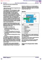
CONTROL DIAGRAM • NOTE: A = Hardwired; B = K bus; M = P bus
Item Part Number Description 1 Battery 2 Fuse 11, CJB 3 DDM 4 Passenger door module 5 Driver exterior mirror 6 Passenger exterior mirror 7 Ambient air temperature sensor 8 Instrument cluster 9 GEM 10 Driver seat memory switch pack 11 Interior mirror 12 Fuse 6, CJB 13 Ignition switch 14 lighting control module (LCM) 15 Maxi fuse 62, CJB 16 Fuse 24, CJB 17 Fuse 43, CJB • NOTE: The hardwired connection between the interior mirror (item number 11) and the GEM (item number 9) is only present on Japanese specification vehicles.
PRINCIPLES OF OPERATION Electrochromic Mirror The electrochromic mirrors automatically dim to reduce glare from the headlights of following vehicles in dark or low light conditions. In addition to dimming the interior mirror, the electrochromic mirror circuits also control the dimming of the two exterior mirrors, via power feed and ground connections with the 2 exterior mirrors. A light sensor on the front of the interior mirror monitors ambient light at the front of the vehicle and a light sensor in the interior mirror glass monitors the light coming from behind the vehicle. When the light from behind the vehicle exceeds the ambient light level, the electrochromic circuits simultaneously dim the interior and exterior mirrors. Dimming is inhibited when reverse gear is selected. The interior mirror is provided with a reverse gear signal by the LCM. For additional information, refer to: Exterior Lighting (417-01, Description and Operation).
Rear View Mirrors - Exterior Mirror Removal and Installation
Removal 1. Remove the front door trim panel. For additional information, refer to: Front Door Trim Panel (501-05, Removal and Installation). 2. Release the window surround trim panel.
3. Remove the exterior mirror. Remove the 3 Torx screws. Disconnect the electrical connector.
Installation 1. Install the interior mirror. Tighten the Torx screws to 8 Nm (6 lb.ft). Connect the electrical connector. 2. Secure the window surround trim panel. 3. Install the front door trim panel. For additional information, refer to: Front Door Trim Panel (501-05, Removal and Installation).
Rear View Mirrors - Exterior Mirror Glass Removal and Installation
Removal 1. Tilt the exterior mirror glass upwards. 2. Release the exterior mirror glass. Carefully apply an even pressure to the base of the glass at two points, to release the 3 clips.
3. Remove the exterior mirror glass. Release the glass from the motor. Disconnect the 2 electrical connectors.
Installation 1. Install the exterior mirror glass. Connect the electrical connectors. Align the glass to the motor. Apply an even pressure to secure glass to the clips. 2. Check the operation of the exterior mirror.
Rear View Mirrors - Exterior Mirror Motor Removal and Installation
Removal 1. Remove the exterior mirror glass. For additional information, refer to: Exterior Mirror Glass (501-09 Rear View Mirrors, Removal and Installation). 2. Remove the exterior mirror motor. Remove the screw. Release the 3 clips. Disconnect the electrical connector.
Installation 1. Install the exterior mirror motor. Connect the electrical connector. Secure the clips. Install the screw. 2. Install the exterior mirror glass. For additional information, refer to: Exterior Mirror Glass (501-09 Rear View Mirrors, Removal and Installation).
Rear View Mirrors - Interior Rear View Mirror Removal and Installation
Removal 1. Remove the 2 trim panels from the interior rear view mirror. Carefully release the 2 trim panels.
2. Release the interior rear view mirror. Reposition the interior rear view mirror.
3. Remove the interior rear view mirror. Disconnect the 2 electrical connectors. Reposition the interior rear view mirror wiring harness from the interior rear view mirror.
Installation 1. Install the interior rear view mirror. Reposition the interior rear view mirror wiring harness to the original position. Connect the 2 electrical connectors. 2. Secure the interior rear view mirror. Reposition the interior rear view mirror. 3. Install the trim panels to the interior rear view mirror.
Seating - Seats Description and Operation
COMPONENT LOCATION
Item 1 2 3
Part Number -
Description Seat switch pack/control module Generic Electronic Module (GEM) Seat relay
OVERVIEW Two variants of driver and passenger seat are available: Low line seat with 8-way adjustment finished in Blenheim leather High line seat with 10-way adjustment finished in Oxford leather
Item Part Number Description A Low line front seat B High line front seat The front seats are fitted with the seat belt bolted to the seat rail. The frames are common to both variants and are equipped with the following: Seat control switches Cushion front height adjustment Cushion rear height adjustment Cushion front tilt adjustment (high line only) Backrest adjustment
Head restraint adjustment Lumbar adjustment Seat forward and rearward adjustment Side air bag module Backrest heating Cushion heating Seat climatic control (available as an option on the high line version)
WARNING: Prior to removal of the front seats and before disconnecting the front seat wiring harness electrical connectors (which includes the side air bag module electrical connectors), the battery ground cable should be disconnected and a period of at least 1 minute allowed to elapse. The same amount of care should be taken when handling and storing the front seats, as would be taken when handling and storing air bag modules. Both variants of the front seats are fitted with a manually adjustable folding armrest on the inboard side of the seat. The memory recall functions are also available on higher specification vehicles. The driver and passenger front seats, although almost identical, have some unique components. The front driver seat has a seat position sensor and the front passenger seat, for North American Specification (NAS) vehicles, has a seat occupant classification system, where as Rest Of the World (ROW) vehicles, except Australia, has a seat occupancy detection system. In both instances the components form an integral part of the Supplemental Restraint System (SRS). For additional information, refer to: Air Bag and Safety Belt Pretensioner Supplemental Restraint System (SRS) (501-20B Supplemental Restraint System, Description and Operation). The rear bench seats are designed to fold forward to increase the rear load space. a 60:40 split gives the owner increased flexibility when loading the vehicle with large objects. All rear seats are equipped with 3-point seat belts and adjustable head restraints. High line specification vehicles are also fitted with seat cushion heaters in both outboard seats.
Integrated Whiplash Reduction System The integrated whiplash reduction system is incorporated into the backrest of the front seats. Head restraint forward positioning is activated by the natural occupant rearward displacement during low speed rear impacts. The head restraint forward positioning is achieved by 10.8 degrees maximum movement of an integral seat deployment paddle.
FRONT SEAT CONTROL SWITCHES • NOTE: Hi-line version shown, lo-line similar.
Item 1 2 3
Part Number -
Description Memory store and preset switches Upper backrest/head restraint adjustment (Hi-line only) Seat backrest adjustment
4 Forward/rearward/cushion height/cushion angle adjustment 5 Lumbar support adjustment The switch pack is mounted on the seat valance of the driver and passenger seats and provides movement in the following axis: Seat forward/rearward adjustment Seat height adjustment Seat angle adjustment Backrest angle adjustment Head restraint height adjustment (electric for hi-line and manual for lo-line) Head Restraint Adjustment
Item Part Number Description 1 Electric head restraint motor Manual adjustment of the seat position can be carried out at any time, having priority over memory recall. For more information regarding seat operation, refer to the owner's handbook.
FRONT SEAT CONTROL COMPONENTS Seat position is monitored by the seat module using seat track position Hall sensors incorporated into the motors. Seat memory is standard on the driver's seat. Each seat memory can be configured for 3 personality positions, which are set using the seat memory switch and stored in the driver seat module. The switches for electrically adjusting the seats are located in the seat pack on the seat valance. The seat module is integral to the switch pack and controls the movement of the seat via hard-wired connections to the motors.
Seat Motors The seat motors are permanent magnet motors. Two pins within the seat switch pack control the motors. Both pins are connected to ground. Operating a switch in one direction will apply voltage to that pin while the other pin remains connected to ground. Operating the switch in the opposite direction reverses power and ground to the motor allowing the motor to run in the opposite direction. The seats can be manually adjusted at any time. Positioning is interrupted if manual adjustment is required during automatic adjustment (memory recall). The manual adjustment is not effective before the switch is operated again. Due to the sequential activation of the drive motors, the switch requests are prioritised in the following order: Forward/rearward adjustment Backrest Height Angle Head restraint Backrest head Steering column angle Steering column forward/rearward adjustment.
HEATED SEATS Front Seats
Item Part Number Description 1 Seat back heater 2 Seat cushion heater 3 Seat back climate control motor (optional on high line variants) 4 Seat cushion climate control motor (optional on high line variants) The seat heater elements are located in the seat cushion and backrest. The cushion and backrest heater elements are wired in series. The cushion heater element has an input feed from the temperature control unit and an output to the backrest heater element, which outputs to ground.
The seat heaters are thermostatically controlled and will operate intermittently to maintain a predetermined temperature. The indicators in the switches will remain illuminated until the heaters are either manually turned off, or the starter switch is turned off. Feedback of the seat temperature is via a Negative Temperature Coefficient (NTC) sensor within the seat cushion. The resistance of this sensor changes with the temperature of the seat cushion allowing the Automatic Temperature Control (ATC) module to raise or lower the voltage to the seat heater elements to raise or lower their temperature. An ignition feed is supplied to each sensor via the relevant seat heater switch.
CAUTION: The seat heaters consume considerable power from the battery. For this reason, they should only be operated while the engine is running. Operation of the heated seats is controlled by the ATC module. Two push-button switches are mounted in the ATC module panel. Each switch has 2 integral Light Emitting Diodes (LED) to display the level of heating selected. For additional information, refer to: Control Components (412-04 Control Components, Description and Operation).
Climatic Seats Seat Controls
Item Part Number Description A Lo-line and hi-line variants with heated front seats B Hi-line variant with seat climatic control option 1 Front seat heater/climatic switches High specification vehicles are fitted with climatic seats, which are able to deliver heating and cooling to the front seat occupants. Vehicles fitted with climatic seats feature 2 additional rotary controllers mounted in the instrument panel switch pack, adjacent to the clock. The rotary controllers are used to select cooling. Three levels of cooling and heating are available, dependant on the degree of switch rotation. The center of the switch is pressed once to ventilate both the seat back and cushion (both indicators on the switch will illuminate). A second press of the switch will ventilate the seat back rest only (the cushion indicator will extinguish).
• NOTE: If climatic seats are fitted, heated seat switches are not featured on the ATC module control panel. • NOTE: The ATC module does not control any aspect of climatic seat operation. The controlling software for the climatic seats is contained within a control module mounted below the driver's seat. When a temperature selection is made through either of the rotary controllers, the instrument panel switch pack provides a Pulse Width Modulation (PWM) signal to the control module. The control module interprets the PWM signal as a temperature value and attempts to heat or cool the seat accordingly. Both climatic front seats contain two Peltier cells; one in the cushion, one in the backrest. The Peltier cells are able to deliver heating and cooling based on a voltage provided by the control module. Each seat also contains a fan, which blows air over the Peltier cells to distribute heating or cooling throughout the seat. The Peltier effect occurs when an electrical current is passed through a junction formed by two dissimilar conductors, creating a heat pump. A heat pump absorbs heat from one side of the system, causing it to cool, and then transfers the heat to the other side, causing it to warm. The cell is capable of cooling the incoming air by approximately 8°C (12.4°F), which means that temperature output will depend on the ambient temperature inside the vehicle. The climatic seat control module monitors seat heating through a NTC temperature sensor. The temperature sensor is only used to monitor seat heating. Seat cooling is open loop, with no temperature signal provided back to the control module. When a temperature selection is made through either of the rotary controllers, the instrument panel switch pack provides a PWM signal to the climatic seat control module, which interprets the PWM signal as a temperature value and attempts to heat or cool the seat accordingly. Although the switch LED's will illuminate if a selection is made when the ignition is switched on, the Peltier cells will not operate until the engine is running. After the ignition is switched off, the climatic seat control module will retain the current temperature settings for approximately 15 minutes. After this period, the seats will be set to „off‟ when the ignition is switched back on. For additional information, refer to: Control Components (412-04 Control Components, Description and Operation).
Rear Seats
Item Part Number Description 1 LH rear seat heater switch 2 RH rear seat heater switch The rear seat heater elements are located in the outboard seat cushion and backrest. The cushion and backrest heater elements are wired in series. The cushion heater element has an input feed from the heater switch and an output to the backrest heater element, which outputs to ground. The seat heaters are thermostatically controlled and will operate intermittently to maintain a predetermined temperature. The indicators in the switches will remain illuminated until the heaters are either manually turned off, or the starter switch is turned off. Feedback of the seat temperature is via a NTC sensor within the seat cushion. The resistance of this sensor changes with the temperature of the seat cushion allowing the rear seat heater switch pack to raise or lower the voltage to the seat heater elements to raise or lower their temperature. An ignition feed is supplied to each sensor via the relevant seat heater switch.
CAUTION: The seat heaters consume considerable power from the battery. For this reason, they should only be operated while the engine is running. Operation of the heated seats is controlled by the ATC module. Two push-button switches are mounted at the rear of the floor console. Each switch has 2 integral Light Emitting Diodes (LED) to display the level of heating selected. For additional information, refer to: Control Components (412-04 Control Components, Description and Operation).
LUMBAR PUMP
Item Part Number Description 1 Bladder 2 Solenoid 3 Pump The lumbar pump inflates a bladder in the backrest, which provides extra support for the seat occupant. With no load on the seat it takes approximately 10 seconds to completely inflate the bladder. With a load of 25 kg (55 lb) it takes approximately 15 seconds to inflate the bladder. A pressure cut off switch in the system will operate at 0.12 to 1.93 bar (1.8 to 28 lbf.in2 ). The lumbar bladder can be replaced independently of the pump. The components are not serviceable.
MEMORY CONTROL MODULE The memory control module, located within the driver switch pack, relies upon a number of inputs to control various outputs. As with all electronic control modules, the unit needs information regarding the current operating conditions of the engine and other related systems before it can make calculations, which determine the appropriate outputs. The memory control module can store up to 3 different driver seating, mirror and steering column positions for each key. All memory values are stored in the non-volatile memory, EEPROM. The current motor positions, which are monitored by the control modules integral Hall sensors, are stored in the EEPROM. If a loss of power occurs, upon power reconnection the current motor position are recalled from the memory and adopted as the current positions. This will allow the relative memory positions to be retained without any need to re-calibrate. The memory control module checks the integrity of all data stored in the EEPROM each time it exit's stand-by mode. In the event that the data is corrupt, the control module adopts the default values for all of the programming options. All memory positions are deemed as invalid and the software will perform as if there are no memory positions stored. Following the procedure for storing a memory position again will reset the relevant memory and allow full functionality.
Memory Function Controlled by the memory module, the memory function stores and recalls the position of the driver's seat, the steering column and the exterior mirrors. The memory recall functions are: Forward/backward adjustment Seat height Seat angle Backrest angle External mirror adjustment Steering column adjustment The seat, steering column, and exterior mirrors will move to the stored position whenever the relevant memory-recall button in pressed. For more information regarding the operation of the memory function, refer to the owner's handbook. • NOTE: Seat, steering column and exterior mirror movement will be halted if any seat adjustment switch (including memory buttons) or the steering column adjustment switch is moved or pressed. To re-start movement of these, the relevant seat memory button will need to be pressed again.
Easy Entry/Exit The 'Easy Entry/Exit' mode provides automatic movement of the steering column to allow easier entry to or exit from the vehicle. • NOTE: If the adjustment switch is moved during entry/exit operation, steering column movement will stop. When the key is inserted in the ignition the steering column will return to their previous positions. If, however, the memorised driver position has been changed (using the seat memory switches or another key transmitter), the steering wheel and seat will move to the new position. When the ignition key is removed, the steering column will move to the uppermost rake.
Stall Detection Seat, steering column and mirror motors are deemed to have stalled if there is no change in the inputs that are received from the corresponding feedback sensors while that axis is being driven. If a stall condition is detected then the drive to that axis is cancelled for the remainder of that memory operation (memory recall) or until the switch is re-selected (manual movement). If the motor movement has stopped due to loss of sensor feedback, either, stall or sensor failure, then that axis may be activated again, to move past the stall position, by re-selecting the appropriate switch. This allows control of the motor to be maintained if sensor feedback is lost. Upon re-selection of movement, if sensor pulses are detected then the motor will continue to be driven until the switch is released or another stall condition is detected. If sensor feedback is not detected then the motor is only driven for 0.5 second and then stops until the switch is released and then pressed again, when a further 0.5 second of activation is permitted, and so on. For all seat motor and steering column manual movements, whenever a motor is driven and a stall occurs, the memory control module records the position at which the stall occurred. If movement occurs beyond a stall position, then that position is erased from the control modules memory. This will always allow movement past a previously recorded stall position once movement has been registered beyond that position. This is the case for both manual and memory movement.
Seating - Seats Diagnosis and Testing
Principles of Operation For a detailed description of the seat systems and operation, refer to the relevant Description and Operation section of the workshop manual. REFER to: Seats (501-10 Seating, Description and Operation).
Inspection and Verification
CAUTION: Diagnosis by substitution from a donor vehicle is NOT acceptable. Substitution of control modules does not guarantee confirmation of a fault and may also cause additional faults in the vehicle being checked and/or the donor vehicle. • NOTE: Check and rectify basic faults before beginning diagnostic routines involving pinpoint tests. 1. Verify the customer concern. 2. Visually inspect for obvious signs of mechanical or electrical damage. Visual Inspection
Mechanical
Seat runners Seat frames Seat movement switch condition and installation Seat heater switch condition and installation Seat motor(s) condition and installation
Electrical Battery condition and state of charge Fuses Harnesses and connectors Seat movement switch(s) Seat heater switch(s) Seat heater elements
Mechanical
Electrical Seat motor(s) Seat module(s) Memory control module(s) Ignition switch Battery Junction Box (BJB) Central Junction Box (CJB)
Local Interconnect Network (LIN) circuit 3. If an obvious cause for an observed or reported concern is found, correct the cause (if possible) before proceeding to the next step. 4. If the cause is not visually evident, verify the symptom and refer to the Symptom Chart, alternatively check for Diagnostic Trouble Codes (DTCs) and refer to the DTC Index.
Symptom Chart Symptom Front seat fore/aft movement not functioning Front seat excessive fore/aft free play Front seat fore/aft movement noisy Front seat height, tilt and/or seat extension motor movement not functioning Front seat height, tilt and/or extension movement noisy
Possible Causes Carry out the pinpoint test to this Symptom Carry out the pinpoint test to this Symptom Carry out the pinpoint test to this Symptom Carry out the pinpoint test to this Symptom Carry out the pinpoint test to this Symptom
Action associated GO to Pinpoint Test A. associated GO to Pinpoint Test B. associated GO to Pinpoint Test C. associated GO to Pinpoint Test D. associated GO to Pinpoint Test E.
DTC Index • NOTE: If the control module is suspect and the vehicle remains under manufacturer warranty, refer to the Warranty Policy and Procedures manual or determine if any prior approval programme is in operation, prior to the installation of a new module. • NOTE: Generic scan tools may not read the codes listed, or may read only five digit codes. Match the five digits from the scan tool to the first five digits of the seven digit code listed to identify the fault (the last two digits give additional information read by the manufacturer approved diagnostic system). • NOTE: When performing electrical voltage or resistance tests, always use a digital multimeter (DMM) accurate to three decimal places, and with an up-to-date calibration certificate. When testing resistance, always take the resistance of the DMM leads into account. • NOTE: Check and rectify basic faults before beginning diagnostic routines involving pinpoint tests. • NOTE: Inspect connectors for signs of water ingress, and pins for damage and/or corrosion. • NOTE: If DTCs are recorded and, after performing the pinpoint tests, a fault is not present, an intermittent concern may be the cause. Always check for loose connections and corroded terminals. Climate Controlled Seat Module
DTC
Description
B10B9- Blower control - Circuit 13 open
Possible Cause The drivers seat cushion heater and blower assembly circuit
Action Check the drivers seat heater and blower assembly for the cushion and backrest circuit. Refer to the electrical guides. Install a new heater and blower assembly if necessary. Clear the DTCs and test for
DTC
Description
Possible Cause open circuit. The drivers seat backrest heater and blower assembly circuit open circuit. Climate Controlled Seat Module failure. The drivers seat cushion heater and blower assembly circuit short circuit to ground.
B10B9- Blower control - Over 4B temperature
The drivers seat backrest heater and blower assembly circuit short circuit to ground. Mechanical restriction in the heater and blower assembly housing. Climate Controlled Seat Module failure. The passenger seat cushion heater and blower assembly circuit open.
Passenger thermal B114Belectric device control 13 Circuit open
The passenger seat backrest heater and blower assembly circuit open circuit. Passenger seat heater and blower assembly failure.
Passenger thermal B114B- electric device control 19 Circuit current above threshold
Climate Controlled Seat Module failure. The passenger seat cushion heater and blower assembly circuit short circuit to ground. The passenger seat backrest heater and blower assembly short circuit to ground.
Action normal operation. Check the Climate Controlled Seat Module ground supply and relay circuits. Refer to the electrical guides. Rectify as necessary. Clear the DTC. Cycle the ignition and retest. If the DTC resets suspect the control module. Refer to the warranty policy and procedures manual if a module is suspect.
Check the drivers seat heater and blower assembly for the cushion and backrest circuit. Refer to the electrical guides. Install a new heater and blower assembly if necessary. Clear the DTCs and test for normal operation. Check the Climate Controlled Seat Module ground supply and relay circuits. Refer to the electrical guides. Rectify as necessary. Clear the DTC. Cycle the ignition and retest. If the DTC resets suspect the control module. Refer to the warranty policy and procedures manual if a module is suspect.
Check the passenger seat heater and blower assembly for the cushion and backrest circuit. Refer to the electrical guides. Install a new heater and blower assembly if necessary. Clear the DTCs and test for normal operation. Check the Climate Controlled Seat Module ground supply and relay circuits. Refer to the electrical guides. Rectify as necessary. Clear the DTC. Cycle the ignition and retest. If the DTC resets suspect the control module. Refer to the warranty policy and procedures manual if a module is suspect.
Check the passenger seat heater and blower assembly for the cushion and backrest circuit. Refer to the electrical guides. Install a new heater and blower assembly if necessary. Clear the DTCs and test for normal operation. Check the Climate Controlled Seat Module ground supply and relay circuits. Refer to the electrical guides. Rectify as necessary. Clear the DTC. Cycle the ignition and retest. If the DTC resets suspect the control module. Refer to the warranty
DTC
Description
Possible Cause Passenger seat heater and blower assembly failure. Climate Controlled Seat Module failure. Passenger seat cushion heater and blower assembly circuit short circuit to ground.
Passenger thermal B114Belectric device control 4B Over temperature
The passenger seat backrest heater and blower assembly short circuit to ground. Passenger seat heater and blower assembly failure. Climate Controlled Seat Module failure. Possible restricted duct. The drivers seat cushion heater and blower assembly circuit open circuit.
Driver thermal electric B114Cdevice control - Circuit 13 open
The drivers seat backrest heater and blower assembly circuit open circuit. Climate Controlled Seat Module failure. The drivers seat cushion heater and blower assembly circuit short circuit to ground.
Driver thermal electric B114Cdevice control - Circuit 19 current above threshold
The drivers seat backrest heater and blower assembly circuit short circuit to ground. Mechanical restriction in the heater and blower assembly housing. Climate Controlled
Action policy and procedures manual if a module is suspect.
Check the passenger seat heater and blower assembly for the cushion and backrest circuit. Refer to the electrical guides. Install a new heater and blower assembly if necessary. Clear the DTCs and test for normal operation. Check the passenger seat and make sure nothing is restricting the seat heater and blower assembly blower duct Rectify as necessary. Clear the DTCs and test for normal operation. Check the Climate Controlled Seat Module ground supply and relay circuits. Refer to the electrical guides. Rectify as necessary. Clear the DTC. Cycle the ignition and retest. If the DTC resets suspect the control module. Refer to the warranty policy and procedures manual if a module is suspect. Check the drivers seat heater and blower assembly for the cushion and backrest circuit. Refer to the electrical guides. Install a new heater and blower assembly if necessary. Clear the DTCs and test for normal operation. Check the Climate Controlled Seat Module ground supply and relay circuits. Refer to the electrical guides. Rectify as necessary. Clear the DTC. Cycle the ignition and retest. If the DTC resets suspect the control module. Refer to the warranty policy and procedures manual if a module is suspect.
Check the drivers seat heater and blower assembly for the cushion and backrest circuit. Refer to the electrical guides. Install a new heater and blower assembly if necessary. Clear the DTCs and test for normal operation. Check the Climate Controlled Seat Module ground supply and relay circuits. Refer to the electrical guides. Rectify as necessary. Clear the DTC. Cycle the ignition and retest. If the DTC resets suspect the control module. Refer to the warranty policy and procedures manual if a module is suspect.
DTC
Description
Driver thermal electric B114Cdevice control - Over 4B temperature
Possible Cause Seat Module failure. The drivers seat cushion heater and blower assembly circuit short circuit to ground. The drivers seat backrest heater and blower assembly circuit short circuit to ground. Mechanical restriction in the heater and blower assembly housing. Possible restricted duct. Climate Controlled Seat Module failure.
Passenger seat cushion B114Dblower speed sensor 11 Circuit short to ground
The passenger seat cushion seat heater and blower assembly circuit short circuit to ground. Internal motor failure. Climate Controlled Seat Module failure.
Passenger seat cushion B114Dblower speed sensor 12 Circuit short to battery
The passenger seat cushion seat heater and blower assembly circuit short circuit to ground. Internal motor failure. Climate Controlled Seat Module failure.
Passenger seat back B114Eblower speed sensor 11 Circuit short to ground
The passenger seat backrest seat heater and blower assembly circuit short circuit to ground. Internal motor failure. Climate Controlled Seat Module
Action
Check the drivers seat heater and blower assembly for the cushion and backrest circuit. Refer to the electrical guides. Install a new heater and blower assembly if necessary. Clear the DTCs and test for normal operation. Check the driver seat cushion and backrest, make sure nothing is restricting the seat heater and blower assembly blower duct. Rectify as necessary. Clear the DTCs and test for normal operation. Check the Climate Controlled Seat Module ground supply and relay circuits. Refer to the electrical guides. Rectify as necessary. Clear the DTC. Cycle the ignition and retest. If the DTC resets suspect the control module. Refer to the warranty policy and procedures manual if a module is suspect.
Check the passenger seat cushion heater and blower assembly circuit. Refer to the electrical guides. Install a new heater and blower assembly if necessary. Clear the DTCs and test for normal operation. Check the Climate Controlled Seat Module ground supply and relay circuits. Refer to the electrical guides. Rectify as necessary. Clear the DTC. Cycle the ignition and retest. If the DTC resets suspect the control module. Refer to the warranty policy and procedures manual if a module is suspect. Check the passenger seat cushion heater and blower assembly circuit. Refer to the electrical guides. Install a new heater and blower assembly if necessary. Clear the DTCs and test for normal operation. Check the Climate Controlled Seat Module ground supply and relay circuits. Refer to the electrical guides. Rectify as necessary. Clear the DTC. Cycle the ignition and retest. If the DTC resets suspect the control module. Refer to the warranty policy and procedures manual if a module is suspect. Check the passenger seat backrest heater and blower assembly circuit. Refer to the electrical guides. Install a new heater and blower assembly if necessary. Clear the DTCs and test for normal operation. Check the Climate Controlled Seat Module ground supply and relay circuits. Refer to the electrical guides. Rectify as necessary. Clear the DTC. Cycle the ignition and retest. If the DTC resets suspect the
DTC
Description
Passenger seat back B114Eblower speed sensor 12 Circuit short to battery
Possible Cause failure.
The passenger seat backrest seat heater and blower assembly circuit short circuit to ground. Internal motor failure. Climate Controlled Seat Module failure.
Driver seat cushion B114Fblower speed sensor 11 Circuit short to ground
The driver seat cushion seat heater and blower assembly circuit short circuit to ground. Internal motor failure. Climate Controlled Seat Module failure.
Driver seat cushion B114Fblower speed sensor 12 Circuit short to battery
The driver seat cushion seat heater and blower assembly circuit short circuit to ground. Internal motor failure. Climate Controlled Seat Module failure.
Driver seat back blower B1150speed sensor - Circuit 11 short to ground
The driver seat backrest seat heater and blower assembly circuit short circuit to ground. Internal motor failure. Climate Controlled Seat Module failure.
Driver seat back blower B1150speed sensor - Circuit 12 short to battery
The driver seat backrest seat heater and blower assembly circuit short circuit to ground.
Action control module. Refer to the warranty policy and procedures manual if a module is suspect. Check the passenger seat backrest heater and blower assembly circuit. Refer to the electrical guides. Install a new heater and blower assembly if necessary. Clear the DTCs and test for normal operation. Check the Climate Controlled Seat Module ground supply and relay circuits. Refer to the electrical guides. Rectify as necessary. Clear the DTC. Cycle the ignition and retest. If the DTC resets suspect the control module. Refer to the warranty policy and procedures manual if a module is suspect. Check the driver seat cushion heater and blower assembly circuit. Refer to the electrical guides. Install a new heater and blower assembly if necessary. Clear the DTCs and test for normal operation. Check the Climate Controlled Seat Module ground supply and relay circuits. Refer to the electrical guides. Rectify as necessary. Clear the DTC. Cycle the ignition and retest. If the DTC resets suspect the control module. Refer to the warranty policy and procedures manual if a module is suspect. Check the driver seat cushion heater and blower assembly circuit. Refer to the electrical guides. Install a new heater and blower assembly if necessary. Clear the DTCs and test for normal operation. Check the Climate Controlled Seat Module ground supply and relay circuits. Refer to the electrical guides. Rectify as necessary. Clear the DTC. Cycle the ignition and retest. If the DTC resets suspect the control module. Refer to the warranty policy and procedures manual if a module is suspect. Check the driver seat backrest heater and blower assembly circuit. Refer to the electrical guides. Install a new heater and blower assembly if necessary. Clear the DTCs and test for normal operation. Check the Climate Controlled Seat Module ground supply and relay circuits. Refer to the electrical guides. Rectify as necessary. Clear the DTC. Cycle the ignition and retest. If the DTC resets suspect the control module. Refer to the warranty policy and procedures manual if a module is suspect. Check the driver seat backrest heater and blower assembly circuit. Refer to the electrical guides. Install a new heater and blower assembly if necessary. Clear the DTCs and test for normal operation. Check the Climate Controlled Seat Module ground supply and relay circuits. Refer to
DTC
Description
Possible Cause Internal motor failure. Climate Controlled Seat Module failure.
B1151- Passenger seat cushion 13 - Circuit open
Passenger seat cushion B1151- Component or system 98 over temperature
B1152- Passenger seat back 13 Circuit open
Passenger seat back B1152Component or system 98 over temperature
B1153- Driver seat cushion 13 Circuit open
Driver seat cushion B1153Component or system 98 over temperature
B1154- Driver seat back 13 Circuit open
Driver seat back B1154Component or system 98 over temperature
B1155- Passenger seat - Fluid 7A leak or seal failure
B1156- Driver seat - Fluid leak
Passenger seat cushion seat fan motor short circuit to ground. Passenger seat cushion over temperature fault. Possible restricted duct. Passenger seat back seat fan motor short circuit to ground. Passenger seat back over temperature fault. Possible restricted duct. Passenger seat cushion seat fan motor short circuit to ground. Driver seat cushion over temperature fault. Possible restricted duct. Passenger seat cushion seat fan motor short circuit to ground. Driver seat back over temperature fault. Possible restricted duct. Possible restricted blower duct on the passenger cushion heater and blower assembly. Possible restricted blower duct on the passenger backrest heater and blower assembly. Possible blower duct adrift. Possible restricted
Action the electrical guides. Rectify as necessary. Clear the DTC. Cycle the ignition and retest. If the DTC resets suspect the control module. Refer to the warranty policy and procedures manual if a module is suspect. Check the front seat heater and blower assembly circuit. Refer to the electrical guides. Install a new front seat heater and blower assembly if necessary. Clear the DTCs and test for normal operation. Check the passenger side front seat and make sure nothing is restricting the seat fan motor blower duct. Rectify as necessary. Clear the DTCs and test for normal operation. Check the front seat heater and blower assembly circuit. Refer to the electrical guides. Install a new front seat heater and blower assembly if necessary. Clear the DTCs and test for normal operation. Check the passenger side front seat and make sure nothing is restricting the seat fan motor blower duct. Rectify as necessary. Clear the DTCs and test for normal operation. Check the front seat heater and blower assembly circuit. Refer to the electrical guides. Install a new front seat heater and blower assembly if necessary. Clear the DTCs and test for normal operation. Check the driver side front seat and make sure nothing is restricting the seat fan motor blower duct. Rectify as necessary. Clear the DTCs and test for normal operation. Check the driver front seat heater and blower assembly circuit. Refer to the electrical guides. Install a new front seat heater and blower assembly if necessary. Clear the DTCs and test for normal operation. Check the driver side front seat and make sure nothing is restricting the seat fan motor blower duct. Rectify as necessary. Clear the DTCs and test for normal operation.
Check the passenger side front seat and make sure the blower duct is not adrift from the heater and blower assembly. Make sure nothing is restricting the seat heater and blower assembly blower duct check the exhaust outlet of each heater and blower assembly. Rectify as necessary. Clear the DTCs and test for normal operation.
Check the driver side front seat and make
DTC 7A
Description or seal failure
Possible Cause blower duct on the driver cushion heater and blower assembly. Possible restricted blower duct on the driver backrest heater and blower assembly. Possible blower duct adrift. The passenger seat cushion heater and blower assembly circuit open circuit.
B1157- Blower control B 13 Circuit open
The passenger seat backrest heater and blower assembly circuit open circuit. Climate Controlled Seat Module failure. The passenger seat cushion heater and blower assembly circuit short circuit to ground.
B1157- Blower control B - Over 4B temperature
The passenger seat backrest heater and blower assembly circuit short circuit to ground. Mechanical restriction in the heater and blower assembly housing.
Action sure the blower duct is not adrift from the heater and blower assembly. Make sure nothing is restricting the seat heater and blower assembly blower duct check the exhaust outlet of each heater and blower assembly. Rectify as necessary. Clear the DTCs and test for normal operation.
Check the passenger seat heater and blower assembly for the cushion and backrest circuit. Refer to the electrical guides. Install a new heater and blower assembly if necessary. Clear the DTCs and test for normal operation. Check the Climate Controlled Seat Module ground supply and relay circuits. Refer to the electrical guides. Rectify as necessary. Clear the DTC. Cycle the ignition and retest. If the DTC resets suspect the control module. Refer to the warranty policy and procedures manual if a module is suspect.
Check the passenger seat heater and blower assembly for the cushion and backrest circuit. Refer to the electrical guides. Install a new heater and blower assembly if necessary. Clear the DTCs and test for normal operation. Check the Climate Controlled Seat Module ground supply and relay circuits. Refer to the electrical guides. Rectify as necessary. Clear the DTC. Cycle the ignition and retest. If the DTC resets suspect the control module. Refer to the warranty policy and procedures manual if a module is suspect.
Climate Controlled Seat Module failure.
CAN signal fault. Medium speed CAN U0010communication bus 88 Bus off
Lost communication U0155- with instrument panel 00 cluster (IPC) control module - No sub type
Check the CAN circuits. Refer to the electrical guides. Rectify as necessary. Clear the DTCs and test for normal operation.
Faulty control module.
Check the control module power supply and relay circuits. Refer to the electrical guides. Rectify as necessary. Clear the DTC. Cycle the ignition and retest. If the DTC resets suspect the control module. Refer to the warranty policy and procedures manual if a module is suspect.
CAN signal fault.
Check the CAN circuits. Refer to the electrical guides. Rectify as necessary. Clear the DTCs and test for normal operation.
Possible open circuit.
DTC
Description information
Internal control module U0300- software incompatibility 00 - No sub type information
Possible Cause
Action
Module not Configured. Incorrect module installed.
Incorrect or invalid software downloaded. Reflash the software with the correct application code for relevant vehicle.
Faulty control module. Control module U2101- configuration 00 incompatible - No sub type information
Module not Configured. Incorrect module installed.
Check the control module power supply and relay circuits. Refer to the electrical guides. Rectify as necessary. Clear the DTC. Cycle the ignition and retest. If the DTC resets suspect the control module. Refer to the warranty policy and procedures manual if a module is suspect.
Possible open circuit. Short circuit to power. Switch pack signal A U2105Signal frequency 38 incorrect
Pulse width modulated (PWM) signal from switchpack to Climate Controlled Seat Module is potentially corrupt. Possible open circuit.
Check the driver PWM signals and circuits. Refer to the electrical guides. Rectify as necessary. Clear the DTCs and test for normal operation.
Short circuit to power. Switch pack signal B U2106Signal frequency 38 incorrect
U3000- Control module 04 System internal failures
PWM signal from switchpack to Climate Controlled Seat Module is potentially corrupt.
Climate Controlled Seat Module failure.
CAN signal fault. U3003- Battery voltage - Signal 62 compare failure
Power supply fault. Instrument Cluster signal fault.
Check the passenger PWM signals and circuits. Refer to the electrical guides. Rectify as necessary. Clear the DTCs and test for normal operation.
Check the control module power supply and relay circuits. Refer to the electrical guides. Rectify as necessary. Clear the DTC. Cycle the ignition and retest. If the DTC resets suspect the control module. Refer to the warranty policy and procedures manual if a module is suspect. Check the Instrument Cluster power supply and relay circuits. Refer to the electrical guides. Rectify as necessary. Clear the DTC. Cycle the ignition and retest. If the DTC resets suspect the Instrument Cluster. Refer to the warranty policy and procedures manual if a module is suspect.
Pinpoint Tests PINPOINT TEST A : FRONT SEAT FORE/AFT MOVEMENT NOT FUNCTIONING TEST DETAILS/RESULTS/ACTIONS CONDITIONS A1: CHECK FOR FRONT SEAT FORWARD-REARWARD SEAT MOTOR OPERATION WARNING: Before work is carried out, make the air bag supplemental restraint system safe. For additional information, refer to Standard Workshop Practices section of workshop manual.
Set ignition status to ' ON'.
1
2 From the switch pack, operate the front seat forward-rearward seat motor switch and listen for evidence of the motor operating. Does the motor operate? Yes GO to A2. No GO to A3. A2: CHECK FRONT SEAT FORWARD-REARWARD SEAT MOTOR DRIVE BAR 1 Check front seat drive bar for correct installation and condition Is the front seat drive bar correctly installed and in a serviceable condition? Yes Re-check for correct front seat forward-rearward movement. Remove seat to allow for further investigation if required. No Correctly install front seat forward-rearward seat motor drive bar, or replace if required. A3: CHECK FRONT SEAT FORWARD-REARWARD SEAT MOTOR WARNING: When carrying out the following steps, stand clear of all moving parts and ensure link harness is routed accordingly. 1 Set ignition status to 'OFF'. 2 Disconnect front seat forward-rearward seat motor connector. • NOTE: It may be that the seat has been driven to the limit of travel along the relevant axis, and when the link harness is connected, the seat will remain in the same position. If this is the case, a jolt may be felt from the motor. To confirm the motor operation, swap the link harness to alternate motor pin connections and the seat should travel in the opposite direction. 3 Using a locally made fused link harness and power supply, connect power and ground to forward-rearward seat motor. Battery positive terminal Battery negative terminal forward-rearward seat motor pin 1 forward-rearward seat motor pin 2 Does the motor operate? Yes Using manufacturer approved diagnostic system, check for related Diagnostic Trouble Codes (DTCs) and carry out the repair operations specified. Alternatively, refer to the electrical circuit diagrams and check front seat forward-rearward seat motor circuits. No Replace front seat forward-rearward seat motor. Refer to relevant section of workshop manual.
PINPOINT TEST B : FRONT SEAT EXCESSIVE FORWARD-REARWARD FREE PLAY TEST DETAILS/RESULTS/ACTIONS CONDITIONS B1: CHECK FRONT SEAT FOR EXCESSIVE FORWARD-REARWARD FREE PLAY WARNING: Before work is carried out, make the air bag supplemental restraint system safe. For additional information, refer to Standard Workshop Practices section of workshop manual. 1
Check all accessible front seat frame fixings are installed and to the correct torque. Are all accessible front seat frame fixings installed and to the correct torque? Yes GO to B2. No Install and tighten all accessible front seat frame fixings to correct torque and re-check for excessive free play. B2: COMPARE THE FRONT SEAT FORWARD-REARWARD FREE PLAY AGAINST A SIMILAR SEAT 1 Compare the front seat forward-rearward free play against a similar seat. Is the front seat forward-rearward free play excessive when compared to a similar seat? Yes GO to B3. No The front seat frame is operating correctly. Submit Electronic Product Quality Report (EPQR) with any further query. B3: CHECK REMAINING FRONT SEAT FRAME FIXINGS 1 Remove front seat and/or any seat covers/trim to allow access to check remaining front seat frame fixings are all installed and to the correct torque. Are all remaining front seat frame fixings installed and to the correct torque? Yes Replace front seat frame. Refer to the relevant section of the workshop manual. No Install and tighten all remaining front seat frame fixings to correct torque and re-check for excessive free play.
PINPOINT TEST C : FRONT SEAT FORWARD-REARWARD MOVEMENT NOISY TEST DETAILS/RESULTS/ACTIONS CONDITIONS C1: COMPARE FRONT SEAT FORWARD-REARWARD MOVEMENT NOISE TO OTHER FRONT SEAT WARNING: Before work is carried out, make the air bag supplemental restraint system safe. For additional information, refer to Standard Workshop Practices section of workshop manual. 1 Compare the front seat forward-rearward movement noise to other front seat. Is the front seat forward-rearward movement noise excessive when compared to other front seat? Yes GO to C2. No GO to C3. C2: COMPARE FRONT SEAT FORWARD-REARWARD MOVEMENT NOISE TO FRONT SEAT IN OTHER VEHICLE 1 Compare the front seat forward-rearward movement noise to front seat in other vehicle. Is the front seat forward-rearward movement noise excessive when compared to front seat in other vehicle? Yes GO to C3. No The front seat frame is operating correctly. Submit Electronic Product Quality Report (EPQR) with any further query. C3: CHECK FOR DEBRIS OBSTRUCTING SEAT MOVEMENT 1 Check for debris obstructing seat movement. Is the front seat forward-rearward movement obstructed by debris? Yes Remove obstruction and re-check for noisy forward-rearward seat movement. No GO to C4. C4: RE-ALIGN FRONT SEAT FRAME 1 Loosen front seat frame fixings. 2 Set ignition status to 'ON'.
3 Using the front seat switch pack drive the front seat fully forward then fully rearward. 4 Tighten front seat frame fixings to the correct torque. 5 Re-check for noisy seat movement. Is the front seat forward-rearward movement still noisy? Yes GO to C5. No The front seat frame is now operating correctly. C5: CHECK FRONT SEAT FORWARD-REARWARD SEAT MOTOR DRIVE BAR 1 Check front seat drive bar for correct installation and condition. Is the front seat drive bar correctly installed and in a serviceable condition? Yes Replace front seat forward-rearward seat motor. Refer to relevant section of workshop manual. No Correctly install front seat forward-rearward seat motor drive bar, or replace if required.
PINPOINT TEST D : FRONT SEAT HEIGHT, TILT AND/OR SEAT EXTENSION MOTOR MOVEMENT NOT FUNCTIONING TEST DETAILS/RESULTS/ACTIONS CONDITIONS D1: CHECK FRONT SEAT HEIGHT, TILT OR EXTENSION MOTOR • WARNINGS:
Before work is carried out, make the air bag supplemental restraint system safe. For additional information, refer to Standard Workshop Practices section of workshop manual. When carrying out the following steps, stand clear of all moving parts and ensure link harness is routed accordingly. 1 Set ignition status to ' OFF'. 2 Disconnect front seat height, tilt or extension motor connector. • NOTE: It may be that the seat has been driven to the limit of travel along the relevant axis, and when the link harness is connected, the seat will remain in the same position. If this is the case, a jolt may be felt from the motor. To confirm the motor operation, swap the link harness to alternate motor pin connections and the seat should travel in the opposite direction. 3 Using a locally made fused link harness and power supply, connect power and ground to relevant motor. Battery positive terminal Battery negative terminal motor pin 1 motor pin 2 Does the motor operate? Yes Using manufacturer approved diagnostic system, check for related Diagnostic Trouble Codes (DTCs) and carry out the repair operations specified. Alternatively, refer to the electrical circuit diagrams and check relevant motor circuits. No Replace the relevant motor. Refer to relevant section of workshop manual.
PINPOINT TEST E : FRONT SEAT HEIGHT, TILT AND/OR EXTENSION MOVEMENT NOISY TEST DETAILS/RESULTS/ACTIONS CONDITIONS E1: COMPARE THE HEIGHT, TILT OR EXTENSION MOVEMENT NOISE WITH THE OTHER FRONT SEAT WARNING: Before work is carried out, make the air bag supplemental restraint system safe. For additional information, refer to Standard Workshop Practices section of workshop manual. 1 Compare the front seat movement noise to other front seat.
Is the front seat height, tilt or extension movement noise excessive when compared to other front seat? Yes GO to E2. No GO to E3. E2: COMPARE FRONT SEAT HEIGHT, TILT OR EXTENSION MOVEMENT NOISE TO FRONT SEAT IN OTHER VEHICLE 1 Compare the front seat height, tilt or extension movement noise to front seat in other vehicle. Is the front seat height, tilt or extension movement noise excessive when compared to front seat in other vehicle? Yes GO to E3. No The front seat frame is operating correctly. Submit Electronic Product Quality Report (EPQR) with any further query. E3: CHECK FOR DEBRIS OBSTRUCTING SEAT MOVEMENT 1 Check for debris obstructing seat movement. Is the front seat height, tilt or extension movement obstructed by debris? Yes Remove obstruction and re-check for noisy height, tilt or extension seat movement. If still noisy GO to E4. No GO to E4. E4: CHECK FOR HEIGHT, TILT OR EXTENSION MOVEMENT MECHANISM LUBRICATION 1 Check and apply manufacturer approved lubrication to seat height, tilt or extension movement mechanism and re-test for noise. Is the front seat height, tilt or extension noise still apparent? Yes Replace the relevant motor. Refer to relevant section of workshop manual. No The front seat height, tilt or extension motor is operating correctly.
Seating - Climate Controlled Seat Switch Removal and Installation
Removal 1. Remove the climate control assembly. For additional information, refer to: Climate Control Assembly (412-04 Control Components, Removal and Installation). 2. Remove the heated front seat switch. Release the 4 clips. Disconnect the 2 electrical connectors.
3. NOTE: Do not disassemble further if the component is removed for access only. Remove the clock. Release the 2 clips.
Installation 1. Install the clock. Secure the 2 clips. 2. Install the heated front seat switch. Connect the 2 electrical connectors. Secure the 4 clips. 3. Install the climate control assembly. For additional information, refer to: Climate Control Assembly (412-04 Control Components, Removal and Installation).
Seating - Front Seat Removal and Installation
Removal • WARNINGS:
Persons working on the supplemental restraint system (SRS) must be fully trained and have been issued with the safety guidelines.
Allow a period of 10 minutes to elapse after disconnecting the battery before undertaking any work on the SRS.
The SRS electrical connectors are unique. DO NOT force, or attempt to connect electrical connectors to the wrong sockets.
The correct procedures must always be used when working on SRS components.
It is imperative that before any work is undertaken on the SRS system, the appropriate information is read thoroughly.
Always disconnect both battery cables before beginning work on the SRS system. Disconnect the ground cable first. Never reverse connect the battery.
Take extra care when handling SRS components.
1. Position the front seat fully forwards. 2. NOTE: Release the front safety belt lower anchor bolt cover clip upwards and away from the front seat base side trim panel. • NOTE: Raise the seat base for access. Remove the safety belt lower anchor bolt cover. 1. Carefully release the clip from behind the front seat base side trim panel. 2. Remove the cover.
3. NOTE: Lower the seat base for access. Release the safety belt lower anchor from the front seat. Remove and discard the bolt.
4. NOTE: Right-hand shown, left-hand similar. Remove the 2 rear bolts from the front seat.
5. NOTE: Right-hand shown, left-hand similar. Remove the 2 front bolts from the front seat. Position the front seat fully rearwards.
6. Reposition the front seat to the central position. Reposition the front seat backrest to the fully upright position.
Lower the front seat head restraint to the fully lowered position. 7. Disconnect the battery ground cable. For additional information, refer to: Specifications (41400 Charging System - General Information, Specifications). 8. Make the air bag supplemental restraint system (SRS) safe. For additional information, refer to: Standard Workshop Practices (100-00 General Information, Description and Operation). 9. Reposition the front seat for access. Disconnect the 4 electrical connectors.
10. NOTE: Ultimate edition only. Reposition the RH front seat for access. Disconnect the 5 electrical connectors.
11. NOTE: Make sure no damage is caused to the vehicle trim when removing the front seat. With assistance carefully remove the front seat. Fit protection around the door aperture to protect the interior.
Installation 1. NOTE: Make sure no damage is caused to the vehicle trim when installing the front seat. With assistance carefully install the front seat. Remove the protection from around the door aperture.
2. CAUTION: Make sure the wiring harness is installed to its original position. Reposition the front seat for access. Connect the 4 electrical connectors. 3. CAUTION: Make sure the wiring harness is installed to its original position. • NOTE: Ultimate edition only. Reposition the front seat for access. Connect the 5 electrical connectors. 4. WARNING: Make sure the front safety belt buckle wiring harness is correctly routed and secured in the position shown. Failure to follow this instruction may result in personal injury.
CAUTION: Make sure the front safety belt buckle wiring harness is correctly routed and secured in the position shown. Failure to follow this instruction may result in damage to the vehicle. Reposition the front safety belt buckle wiring harness. 5. Connect the battery ground cable. For additional information, refer to: Specifications (41400 Charging System - General Information, Specifications). 6. NOTE: Make sure the 3 seat rail covers are fitted to their original positions. Note: The inner front seat rail does not have a seat rail cover. Install the 2 front bolts to the front seat. Align the front seat locating pegs. Position the front seat fully rearwards. Tighten the front seat front bolts to 45 Nm (33 lb.ft). 7. NOTE: Make sure the 3 seat rail covers are fitted to their original positions. Note: The inner front seat rail does not have a seat rail cover. Install the 2 rear bolts to the front seat. Position the front seat fully forwards. Tighten the front seat rear bolts to 45 Nm (33 lb.ft). 8. Attach the safety belt lower anchor to the seat. Install a new bolt and tighten to 45 Nm (33 lb.ft). 9. Install the safety belt lower anchor bolt cover. 10. Reposition the front seat to the original position.
Seating - Front Seat Backrest Cover Removal and Installation
Removal • WARNINGS:
Persons working on the supplemental restraint system (SRS) must be fully trained and have been issued with the safety guidelines.
Allow a period of 10 minutes to elapse after disconnecting the battery before undertaking any work on the SRS.
The SRS electrical connectors are unique. DO NOT force, or attempt to connect electrical connectors to the wrong sockets.
The correct procedures must always be used when working on SRS components.
It is imperative that before any work is undertaken on the SRS system, the appropriate information is read thoroughly.
Always disconnect both battery cables before beginning work on the SRS system. Disconnect the ground cable first. Never reverse connect the battery.
Take extra care when handling SRS components. 1. Disconnect the battery ground cable. For additional information, refer to: Specifications (41400, Specifications). 2. Make the air bag supplemental restraint system (SRS) safe. For additional information, refer to: Standard Workshop Practices (100-00 General Information, Description and Operation). 3. Remove the front seat head restraint. For additional information, refer to: Front Seat Head Restraint - Vehicles With: Head Restraint Video Display (501-10, Removal and Installation). 4. Remove the seat armrest. For additional information, refer to: Seat Armrest (50110 Seating, Removal and Installation). 5. Remove the front seat backrest cover upper trim panel. Remove the 2 screws. Release the front seat backrest cover from the front seat backrest upper trim panel.
6. Remove the front seat backrest cooling duct. Remove the clip from the front seat backrest cooling duct.
7. Remove and discard the 2 clips from the front seat backrest cover.
8. Release the 2 outer tension straps from the front seat backrest.
9. WARNING: The air bag is mounted directly under this component, extreme care is necessary. Failure to follow this instruction may result in personal injury. Release the front seat side air bag sleeve from the front seat backrest cover outer tension strap.
10. Reposition the lumbar motor control valve.
11. WARNING: The air bag is mounted directly under this component, extreme care is necessary. Failure to follow this instruction may result in personal injury. Release the front seat side air bag sleeve. Remove and discard the front seat side air bag sleeve bolt. Remove and discard the front seat side air bag lower nut. 12. Reposition the front seat backrest heater and blower motor assembly. Carefully release the 2 clips.
13. Reposition the front seat backrest heater and blower motor assembly duct. Release the 2 clips.
14. Release the 3 inner central tension straps from the front seat backrest. Reposition the front seat backrest cover inner central tension straps to the front.
15. Remove the front seat head restraint guide tubes. Raise the front seat backrest cover from the front seat frame for access. Carefully release the 2 clips from the front seat head restraint guide tubes.
16. Remove the front seat backrest cushion and cover from the front seat frame. 17. NOTE: Do not disassemble further if the component is removed for access only. Remove the front seat backrest cover from the front seat backrest cushion. Reposition the front seat backrest cover from the front seat backrest cushion. Remove and discard the 17 clips from the front seat backrest cover.
Installation 1. Install the front seat backrest cover to the front seat backrest cushion. Reposition the front seat backrest cover to the front seat backrest cushion. Install the 17 new clips to the front seat backrest cover. 2. Install the front seat backrest cushion and cover to the front seat frame. 3. Install the front seat head restraint guide tubes. Secure the head restraint guide tube clips. Reposition the front seat backrest cover to the original position.
4. WARNING: Make sure the front seat air bag sleeve and front seat backrest cover outer tension straps, are secure and correctly installed to the front seat frame to allow the air bag to deploy correctly. Failure to follow this instruction may result in personal injury.
CAUTION: Make sure the front seat air bag sleeve and front seat backrest cover outer tension straps, are secure and correctly installed to the front seat frame to allow the air bag to deploy correctly. Failure to follow this instruction may result in damage to the vehicle. Secure the 3 inner central tension straps to the front seat backrest. Reposition the front seat backrest cover inner central tension straps to the rear. 5. Reposition the front seat backrest heater and blower motor assembly duct. Secure the 2 clips. 6. Reposition the front seat backrest heater and blower motor assembly. Secure the 2 clips. 7. WARNINGS:
Make sure the front seat air bag sleeve and front seat backrest cover outer tension straps, are secure and correctly installed to the front seat frame to allow the air bag to deploy correctly. Failure to follow this instruction may result in personal injury.
The air bag is mounted directly under this component, extreme care is necessary. Failure to follow this instruction may result in personal injury.
CAUTION: Make sure the front seat air bag sleeve and front seat backrest cover outer tension straps, are secure and correctly installed to the front seat frame to allow the air bag to deploy correctly. Failure to follow this instruction may result in damage to the vehicle. Secure the front seat side air bag sleeve. Tighten the new bolt to 3 Nm (2 lb.ft). Tighten the new nut to 7 Nm (5 lb.ft). 8. Reposition the lumbar motor control valve.
9. WARNINGS:
Make sure the front seat air bag sleeve and front seat backrest cover outer tension straps, are secure and correctly installed to the front seat frame to allow the air bag to deploy correctly. Failure to follow this instruction may result in personal injury.
The air bag is mounted directly under this component, extreme care is necessary. Failure to follow this instruction may result in personal injury.
CAUTION: Make sure the front seat air bag sleeve and front seat backrest cover outer tension straps, are secure and correctly installed to the front seat frame to allow the air bag to deploy correctly. Failure to follow this instruction may result in damage to the vehicle. Secure the front seat side air bag sleeve to the front seat backrest cover outer tension strap. 10. WARNING: Make sure the front seat air bag sleeve and front seat backrest cover outer tension straps, are secure and correctly installed to the front seat frame to allow the air bag to deploy correctly. Failure to follow this instruction may result in personal injury.
CAUTION: Make sure the front seat air bag sleeve and front seat backrest cover outer tension straps, are secure and correctly installed to the front seat frame to allow the air bag to deploy correctly. Failure to follow this instruction may result in damage to the vehicle. Secure the 2 outer tension straps to the front seat backrest. 11. Install the 2 new clips to the front seat backrest cover. 12. Install the front seat backrest cooling duct. Install the clip to the front seat backrest cooling duct. 13. Install the front seat backrest cover upper trim panel. Install the front seat backrest cover to the front seat backrest upper trim panel. Install the 2 screws. 14. Install the seat armrest. For additional information, refer to: Seat Armrest (50110 Seating, Removal and Installation). 15. Install the front seat head restraint. For additional information, refer to: Front Seat Head Restraint - Vehicles With: Head Restraint Video Display (501-10, Removal and Installation). 16. Connect the battery ground cable. For additional information, refer to: Specifications (41400, Specifications).
Seating - Front Seat Backrest Lower Rear Cover Removal and Installation
Removal • WARNINGS:
Persons working on the supplemental restraint system (SRS) must be fully trained and have been issued with the safety guidelines.
Allow a period of 10 minutes to elapse after disconnecting the battery before undertaking any work on the SRS.
The SRS electrical connectors are unique. DO NOT force, or attempt to connect electrical connectors to the wrong sockets.
The correct procedures must always be used when working on SRS components.
It is imperative that before any work is undertaken on the SRS system, the appropriate information is read thoroughly.
Always disconnect both battery cables before beginning work on the SRS system. Disconnect the ground cable first. Never reverse connect the battery.
Take extra care when handling SRS components. 1. Disconnect the battery ground cable. For additional information, refer to: Specifications (41400, Specifications). 2. Make the air bag supplemental restraint system (SRS) safe. For additional information, refer to: Standard Workshop Practices (100-00 General Information, Description and Operation). 3. Remove the front seat. For additional information, refer to: Front Seat (501-10 Seating, Removal and Installation). 4. Release the 2 lower tension straps from the front seat base. Reposition the front seat backrest cover for access.
5. Remove the front seat side trim panel support. Release the 2 clips.
6. Remove the seat control switch. For additional information, refer to: Seat Control Switch (501-10 Seating, Removal and Installation). 7. Remove the front seat backrest hinge cover. Remove the 2 screws. Release the clip.
8. NOTE: Left-hand shown, right-hand similar. Remove the 2 clips from the front seat backrest lower rear cover.
9. Remove the front seat backrest lower rear cover. Release the front seat backrest cover lower trim panel from the 2 clips.
Installation 1. Install the front seat backrest lower rear cover. Secure the front seat backrest cover lower trim panel to the 2 clips. 2. Install the 2 clips to the front seat backrest lower rear cover. 3. Install the front seat backrest hinge cover. Secure the clip. Install the 2 screws. 4. Install the seat control switch. For additional information, refer to: Seat Control Switch (501-10 Seating, Removal and Installation). 5. Install the front seat side trim panel support. Secure the 2 clips. 6. Secure the 2 lower tension straps to the front seat base. Reposition the front seat backrest cover. 7. Install the front seat. For additional information, refer to: Front Seat (501-10 Seating, Removal and Installation). 8. Connect the battery ground cable. For additional information, refer to: Specifications (41400, Specifications).
Seating - Front Seat Backrest Heater and Blower Assembly Removal and Installation
Removal • WARNINGS:
Persons working on the supplemental restraint system (SRS) must be fully trained and have been issued with the safety guidelines.
Allow a period of 10 minutes to elapse after disconnecting the battery before undertaking any work on the SRS.
The SRS electrical connectors are unique. DO NOT force, or attempt to connect electrical connectors to the wrong sockets.
The correct procedures must always be used when working on SRS components.
It is imperative that before any work is undertaken on the SRS system, the appropriate information is read thoroughly.
Always disconnect both battery cables before beginning work on the SRS system. Disconnect the ground cable first. Never reverse connect the battery.
Take extra care when handling SRS components.
1. Disconnect the battery ground cable. For additional information, refer to: Specifications (41400, Specifications). 2. Make the air bag supplemental restraint system (SRS) safe. For additional information, refer to: Standard Workshop Practices (100-00 General Information, Description and Operation). 3. Remove the front seat backrest lower rear cover. For additional information, refer to: Front Seat Backrest Lower Rear Cover (501-10 Seating, Removal and Installation). 4. Remove the front seat backrest cooling duct. Remove the clip from the front seat backrest cooling duct.
5. Remove and discard the clip from the front seat backrest cover.
6. Release the front seat backrest cover RH inner tension strap.
7. Reposition the front seat backrest heater and blower motor assembly. Carefully release the 2 clips.
8. Remove the 3 screws from the front seat backrest heater and blower motor assembly.
9. Remove the front seat backrest heater and blower motor assembly. Disconnect the front seat backrest heater and blower motor assembly electrical connector.
Installation 1. Install the front seat backrest heater and blower motor assembly. Connect the front seat backrest heater and blower motor assembly electrical connector. 2. Install the 3 screws to the front seat backrest heater and blower motor assembly. 3. Reposition the front seat backrest heater and blower motor assembly. Secure the 2 clips. 4. Secure the front seat backrest cover RH inner tension strap. 5. Install the new clip to the front seat backrest cover. 6. Install the front seat backrest cooling duct. Install the clip to the front seat backrest cooling duct.
7. Install the front seat backrest lower rear cover. For additional information, refer to: Front Seat Backrest Lower Rear Cover (501-10 Seating, Removal and Installation). 8. Connect the battery ground cable. For additional information, refer to: Specifications (41400, Specifications).
Seating - Front Seat Cushion Heater and Blower Assembly Removal and Installation
Removal • WARNINGS:
Persons working on the supplemental restraint system (SRS) must be fully trained and have been issued with the safety guidelines.
Allow a period of 10 minutes to elapse after disconnecting the battery before undertaking any work on the SRS.
The SRS electrical connectors are unique. DO NOT force, or attempt to connect electrical connectors to the wrong sockets.
The correct procedures must always be used when working on SRS components.
It is imperative that before any work is undertaken on the SRS system, the appropriate information is read thoroughly.
Always disconnect both battery cables before beginning work on the SRS system. Disconnect the ground cable first. Never reverse connect the battery.
Take extra care when handling SRS components. 1. Disconnect the battery ground cable. For additional information, refer to: Specifications (41400, Specifications). 2. Make the air bag supplemental restraint system (SRS) safe. For additional information, refer to: Standard Workshop Practices (100-00 General Information, Description and Operation). 3. Remove the front seat cushion and front seat cushion cover from the front seat base. For additional information, refer to: Front Seat Cushion Cover (501-10 Seating, Removal and Installation).
4. Reposition the front seat base wiring harness trim panel. Reposition the front seat for access. Remove the 4 screws.
5. Remove the front seat cushion heater and blower motor assembly duct. Remove the screw.
6. Remove the 3 screws from the front seat heater and blower motor assembly.
7. Remove the front seat cushion heater and blower motor assembly. Disconnect the front seat cushion heater and blower motor assembly electrical connector.
Installation 1. Install the front seat cushion heater and blower motor assembly. Connect the front seat cushion heater and blower motor assembly electrical connector. 2. Install the 3 screws to the front seat cushion heater and blower motor assembly. 3. Install the front seat cushion heater and blower motor assembly duct. Install the screw. 4. Reposition the front seat base wiring harness trim panel. Reposition the front seat for access. Install the 4 screws. 5. Install the front seat cushion and cover to the front seat base. For additional information, refer to: Front Seat Cushion Cover (501-10 Seating, Removal and Installation). 6. Connect the battery ground cable. For additional information, refer to: Specifications (41400, Specifications).
Seating - Front Seat Cushion Cover Removal and Installation
Removal • WARNINGS:
Persons working on the supplemental restraint system (SRS) must be fully trained and have been issued with the safety guidelines.
Allow a period of 10 minutes to elapse after disconnecting the battery before undertaking any work on the SRS.
The SRS electrical connectors are unique. DO NOT force, or attempt to connect electrical connectors to the wrong sockets.
The correct procedures must always be used when working on SRS components.
It is imperative that before any work is undertaken on the SRS system, the appropriate information is read thoroughly.
Always disconnect both battery cables before beginning work on the SRS system. Disconnect the ground cable first. Never reverse connect the battery.
Take extra care when handling SRS components.
CAUTION: The front passenger seat occupant classification sensor is available only as a service kit. No attempt should be made to replace individual components. Failure to follow this instruction may result in personal injury. 1. Disconnect the battery ground cable. For additional information, refer to: Specifications (41400, Specifications). 2. Make the air bag supplemental restraint system (SRS) safe. For additional information, refer to: Standard Workshop Practices (100-00 General Information, Description and Operation). 3. Remove the front seat. For additional information, refer to: Front Seat (501-10 Seating, Removal and Installation). 4. Release the 2 lower tension straps from the front seat base. Reposition the front seat backrest cover for access.
5. Remove the front seat side trim panel support. Release the 2 clips.
6. Remove the seat control switch. For additional information, refer to: Seat Control Switch (501-10 Seating, Removal and Installation). 7. Remove the front seat base side trim panel mounting bracket. Release the 2 wiring harness clips. Remove the 4 screws.
8. Remove the front seat backrest hinge cover. Remove the 2 screws. Release the clip.
9. NOTE: Left-hand shown, right-hand similar. Remove the 2 clips from the front seat backrest cover lower trim panel.
10. Remove the front seat backrest cover lower trim panel. Release the front seat backrest cover lower trim panel from the 2 clips.
11. WARNING: The front seat base has sharp edges, hand protection must be worn when releasing the front seat cushion cover from the front seat base. Failure to follow this instruction may result in personal injury. Release the front seat cushion cover from the rear of the front seat base.
12. WARNING: The front seat base has sharp edges, hand protection must be worn when releasing the front seat cushion cover from the front seat base. Failure to follow this instruction may result in personal injury. • NOTE: Left-hand shown, right-hand similar. Release the front seat cushion cover from the lefthand side of the front seat base.
13. WARNING: The front seat base has sharp edges, hand protection must be worn when releasing the front seat cushion cover from the front seat base. Failure to follow this instruction may result in personal injury. Release the front seat cushion cover from the right-hand side of the front seat base. 14. WARNING: The front seat base has sharp edges, hand protection must be worn when releasing the front seat cushion cover from the front seat base. Failure to follow this instruction may result in personal injury. Remove the front seat cushion and front seat cushion cover from the front seat base. Reposition the front seat for access. Release the front seat cushion cover from the front of the front seat base. 15. NOTE: Do not disassemble further if the component is removed for access only. Release the front seat cushion cover tension strap.
16. Remove and discard the 15 clips from the front seat cushion cover. Reposition the front seat cushion cover for access.
17. Remove the front seat cushion cover from the front seat cushion.
Installation 1. Install the front seat cushion cover to the front seat cushion. 2. Install the 15 new clips to the front seat cushion cover. Reposition the front seat cushion cover to the front seat cushion. 3. Secure the front seat cushion cover tension strap. 4. WARNING: The front seat base has sharp edges, hand protection must be worn when securing the front seat cushion cover to front seat base. Failure to follow this instruction may result in personal injury. Install the front seat cushion and cover to the front seat base. Reposition the front seat for access. Secure the front seat cushion cover to the front of the front seat base. 5. WARNING: The front seat base has sharp edges, hand protection must be worn when securing the front seat cushion cover to front seat base. Failure to follow this instruction may result in personal injury. Secure the front seat cushion cover to the right-hand side of the front seat base. 6. WARNING: The front seat base has sharp edges, hand protection must be worn when securing the front seat cushion cover to front seat base. Failure to follow this instruction may result in personal injury. Secure the front seat cushion cover to the left-hand side of the front seat base. 7. WARNING: The front seat base has sharp edges, hand protection must be worn when securing the front seat cushion cover to front seat base. Failure to follow this instruction may result in personal injury. Secure the front seat cushion cover to the rear of the front seat base.
8. Install the front seat backrest cover lower trim panel. Secure the front seat backrest cover lower trim panel to the 2 clips. 9. Install the 2 clips to the front seat backrest cover lower trim panel. 10. Install the front seat backrest hinge cover. Secure the clip. Install the 2 screws. 11. Install the front seat base side trim panel mounting bracket. Install the 4 screws. Secure the 2 wiring harness clips. 12. Install the seat control switch. For additional information, refer to: Seat Control Switch (501-10 Seating, Removal and Installation). 13. Install the front seat side trim panel support. Secure the 2 clips. 14. Secure the 2 lower tension straps to the front seat base. Reposition the front seat backrest cover. 15. Install the front seat. For additional information, refer to: Front Seat (501-10 Seating, Removal and Installation). 16. Connect the battery ground cable. For additional information, refer to: Specifications (41400, Specifications). 17. Using the Land Rover approved diagnostic system, calibrate the occupant classification sensor.
Seating - Front Seat Head RestraintVehicles With: Head Restraint Video Display Removal and Installation
Removal • WARNINGS:
Persons working on the supplemental restraint system (SRS) must be fully trained and have been issued with the safety guidelines.
Allow a period of 10 minutes to elapse after disconnecting the battery before undertaking any work on the SRS.
The SRS electrical connectors are unique. DO NOT force, or attempt to connect electrical connectors to the wrong sockets.
The correct procedures must always be used when working on SRS components.
It is imperative that before any work is undertaken on the SRS system, the appropriate information is read thoroughly.
Always disconnect both battery cables before beginning work on the SRS system. Disconnect the ground cable first. Never reverse connect the battery.
Take extra care when handling SRS components. 1. Reposition the front seat backrest for access. Reposition the front seat head restraint to the fully extended position. 2. Disconnect the battery ground cable. For additional information, refer to: Specifications (41400, Specifications). 3. Make the air bag supplemental restraint system (SRS) safe. For additional information, refer to: Standard Workshop Practices (100-00 General Information, Description and Operation). 4. Remove the front seat backrest cover lower trim panel. For additional information, refer to: Front Seat Backrest Lower Rear Cover (501-10 Seating, Removal and Installation). 5. Disconnect the front seat head restraint video display electrical connector. Release the clip.
6. CAUTION: Make sure that the head restraint is not withdrawn further than 15 mm (0.60 inch) from the head restraint guide tubes. Release the front seat head restraint. Release the front seat head restraint from the head restraint clips.
7. Using a suitable tape secure the front seat head restraint post clip to the front seat head restraint wiring harness. Release the front seat head restraint post clip from the RH head restraint post.
8. Release the RH head restraint guide tube. Apply suitable protective tape around the RH head restraint guide tube. Using a suitable tool, release the RH head restraint guide tube.
9. CAUTION: Make sure no damage occurs to the video display wiring harness. • NOTE: Note the position of the wiring harnesses to aid installation. Remove the front seat head restraint. Feed the front seat head restraint video wiring harness through the front seat backrest cover and the seat frame.
Installation 1. CAUTIONS:
Make sure the wiring harness is installed to its original position.
Make sure no damage occurs to the video display wiring harness. Install the front seat head restraint. Feed the front seat head restraint video wiring harness through the front seat backrest cover and the seat frame. 2. Secure the RH head restraint guide tube. Remove the protective tape from around the RH head restraint guide tube.
3. Remove the suitable tape from the front seat head restraint post clip. Secure the front seat head restraint post clip to the RH head restraint post. 4. CAUTION: Make sure the plastic insert is correctly installed to the RH head restraint post. Failure to follow this instruction may result in damage to the vehicle. Secure the front seat head restraint. Secure the front seat head restraint to the head restraint clips. 5. Connect the front seat head restraint video display electrical connector. Secure the clip. 6. Install the front seat backrest cover lower trim panel. For additional information, refer to: Front Seat Backrest Lower Rear Cover (501-10 Seating, Removal and Installation). 7. Connect the battery ground cable. For additional information, refer to: Specifications (41400, Specifications). 8. Reposition the front seat backrest to its original position. Reposition the front seat head restraint to its original position.
Seating - Front Seat Head RestraintVehicles Without: Head Restraint Video Display Removal and Installation
Removal 1. Reposition the front seat backrest for access. 2. WARNING: The head restraint will release suddenly, keep face clear during removal. Failure to follow this instruction may result in personal injury. Remove the front seat head restraint. Reposition the front seat head restraint to the fully extended position. Release the front seat head restraint from the head restraint clips.
Installation 1. Install the front seat head restraint. Secure the front seat head restraint to the head restraint clips. Reposition the front seat head restraint to the original position. 2. Reposition the front seat backrest to the original
position.
Seating - Front Seat Head Restraint Motor Removal and Installation
Removal • WARNINGS:
Persons working on the supplemental restraint system (SRS) must be fully trained and have been issued with the safety guidelines.
Allow a period of 10 minutes to elapse after disconnecting the battery before undertaking any work on the SRS.
The SRS electrical connectors are unique. DO NOT force, or attempt to connect electrical connectors to the wrong sockets.
The correct procedures must always be used when working on SRS components.
It is imperative that before any work is undertaken on the SRS system, the appropriate information is read thoroughly.
Always disconnect both battery cables before beginning work on the SRS system. Disconnect the ground cable first. Never reverse connect the battery.
Take extra care when handling SRS components. 1. Disconnect the battery ground cable. For additional information, refer to: Specifications (41400, Specifications). 2. Make the air bag supplemental restraint system (SRS) safe. For additional information, refer to: Standard Workshop Practices (100-00 General Information, Description and Operation). 3. Remove the front seat head restraint. For additional information, refer to: Front Seat Head Restraint - Vehicles With: Head Restraint Video Display (501-10, Removal and Installation). 4. Remove the seat armrest. For additional information, refer to: Seat Armrest (50110 Seating, Removal and Installation).
5. Remove the front seat backrest cover upper trim panel. Remove the 2 screws. Release the front seat backrest cover from the front seat backrest upper trim panel.
6. Remove the front seat backrest cooling duct. Remove the clip from the front seat backrest cooling duct.
7. Remove and discard the 2 clips from the front seat backrest cover.
8. Release the 2 outer tension straps from the front seat backrest.
9. WARNING: The air bag is mounted directly under this component, extreme care is necessary. Failure to follow this instruction may result in personal injury. Release the front seat side air bag sleeve from the front seat backrest cover outer tension strap.
10. Reposition the lumbar motor control valve.
11. WARNING: The air bag is mounted directly under this component, extreme care is necessary. Failure to follow this instruction may result in personal injury. Release the front seat side air bag sleeve. Remove and discard the front seat side air bag sleeve bolt. Remove and discard the front seat side air bag lower nut. 12. Reposition the front seat backrest heater and blower motor assembly. Carefully release the 2 clips.
13. Reposition the front seat backrest heater and blower motor assembly duct. Release the 2 clips.
14. Release the 3 inner central tension straps from the front seat backrest. Reposition the front seat backrest cover inner central tension straps to the front.
15. Remove the front seat head restraint motor screw. Raise the front seat backrest cover from the front seat frame for access.
16. Remove the front seat head restraint motor. Disconnect the electrical connector. Release the front seat head restraint motor from the front seat frame.
Installation 1. Install the front seat head restraint motor. Secure the front seat head restraint motor to the front seat frame. Connect the electrical connector.
2. Install the front seat head restraint motor screw. Reposition the front seat backrest cover to the original position. 3. WARNING: Make sure the front seat air bag sleeve and front seat backrest cover outer tension straps, are secure and correctly installed to the front seat frame to allow the air bag to deploy correctly. Failure to follow this instruction may result in personal injury.
CAUTION: Make sure the front seat air bag sleeve and front seat backrest cover outer tension straps, are secure and correctly installed to the front seat frame to allow the air bag to deploy correctly. Failure to follow this instruction may result in damage to the vehicle. Secure the 3 inner central tension straps to the front seat backrest. Reposition the front seat backrest cover inner central tension straps to the rear. 4. Reposition the front seat backrest heater and blower motor assembly duct. Secure the 2 clips. 5. Reposition the front seat backrest heater and blower motor assembly. Secure the 2 clips. 6. WARNINGS:
Make sure the front seat air bag sleeve and front seat backrest cover outer tension straps, are secure and correctly installed to the front seat frame to allow the air bag to deploy correctly. Failure to follow this instruction may result in personal injury.
The air bag is mounted directly under this component, extreme care is necessary. Failure to follow this instruction may result in personal injury.
CAUTION: Make sure the front seat air bag sleeve and front seat backrest cover outer tension straps, are secure and correctly installed to the front seat frame to allow the air bag to deploy correctly. Failure to follow this instruction may result in damage to the vehicle. Secure the front seat side air bag sleeve. Tighten the new bolt to 3 Nm (2 lb.ft). Tighten the new nut to 7 Nm (5 lb.ft). 7. Reposition the lumbar motor control valve.
8. WARNINGS:
Make sure the front seat air bag sleeve and front seat backrest cover outer tension straps, are secure and correctly installed to the front seat frame to allow the air bag to deploy correctly. Failure to follow this instruction may result in personal injury.
The air bag is mounted directly under this component, extreme care is necessary. Failure to follow this instruction may result in personal injury.
CAUTION: Make sure the front seat air bag sleeve and front seat backrest cover outer tension straps, are secure and correctly installed to the front seat frame to allow the air bag to deploy correctly. Failure to follow this instruction may result in damage to the vehicle. Secure the front seat side air bag sleeve to the front seat backrest cover outer tension strap. 9. WARNING: Make sure the front seat air bag sleeve and front seat backrest cover outer tension straps, are secure and correctly installed to the front seat frame to allow the air bag to deploy correctly. Failure to follow this instruction may result in personal injury.
CAUTION: Make sure the front seat air bag sleeve and front seat backrest cover outer tension straps, are secure and correctly installed to the front seat frame to allow the air bag to deploy correctly. Failure to follow this instruction may result in damage to the vehicle. Secure the 2 outer tension straps to the front seat backrest. 10. Install the 2 new clips to the front seat backrest cover. 11. Install the front seat backrest cooling duct. Install the clip to the front seat backrest cooling duct. 12. Install the front seat backrest cover upper trim panel. Install the front seat backrest cover to the front seat backrest upper trim panel. Install the 2 screws. 13. Install the seat armrest. For additional information, refer to: Seat Armrest (50110 Seating, Removal and Installation). 14. Install the front seat head restraint. For additional information, refer to: Front Seat Head Restraint - Vehicles With: Head Restraint Video Display (501-10, Removal and Installation). 15. Connect the battery ground cable. For additional information, refer to: Specifications (41400, Specifications).
Seating - Front Seat Recliner Motor Removal and Installation
Removal • WARNINGS:
Persons working on the supplemental restraint system (SRS) must be fully trained and have been issued with the safety guidelines.
Allow a period of 10 minutes to elapse after disconnecting the battery before undertaking any work on the SRS.
The SRS electrical connectors are unique. DO NOT force, or attempt to connect electrical connectors to the wrong sockets.
The correct procedures must always be used when working on SRS components.
It is imperative that before any work is undertaken on the SRS system, the appropriate information is read thoroughly.
Always disconnect both battery cables before beginning work on the SRS system. Disconnect the ground cable first. Never reverse connect the battery.
Take extra care when handling SRS components. 1. Disconnect the battery ground cable. For additional information, refer to: Specifications (41400, Specifications). 2. Make the air bag supplemental restraint system (SRS) safe. For additional information, refer to: Standard Workshop Practices (100-00 General Information, Description and Operation). 3. Remove the front seat backrest cover. For additional information, refer to: Front Seat Backrest Cover (501-10 Seating, Removal and Installation). 4. Reposition the front seat backrest shaft. Remove and discard the front seat backrest shaft clip.
5. Remove the front seat recliner motor. Disconnect the electrical connector. Remove the front seat recliner motor bolt.
6. Remove the front seat recliner motor bracket. Release the 2 clips.
Installation 1. Install the front seat recliner motor bracket. Secure the 2 clips. 2. Install the front seat recliner motor. Loosely install the front seat recliner motor bolt. Connect the electrical connector. 3. Reposition the front seat backrest shaft. Install the new front seat backrest shaft clip. Tighten the front seat recliner motor bolt. 4. Install the front seat backrest cover. For additional information, refer to: Front Seat Backrest Cover (501-10 Seating, Removal and Installation). 5. Make the air bag supplemental restraint system (SRS) safe. For additional information, refer to: Standard Workshop Practices (100-00 General Information, Description and Operation). 6. Connect the battery ground cable. For additional information, refer to: Specifications (41400, Specifications).
Seating - Lumbar Assembly Removal and Installation
Removal • WARNINGS:
Persons working on the supplemental restraint system (SRS) must be fully trained and have been issued with the safety guidelines.
Allow a period of 10 minutes to elapse after disconnecting the battery before undertaking any work on the SRS.
The SRS electrical connectors are unique. DO NOT force, or attempt to connect electrical connectors to the wrong sockets.
The correct procedures must always be used when working on SRS components.
It is imperative that before any work is undertaken on the SRS system, the appropriate information is read thoroughly.
Always disconnect both battery cables before beginning work on the SRS system. Disconnect the ground cable first. Never reverse connect the battery.
Take extra care when handling SRS components. 1. Disconnect the battery ground cable. For additional information, refer to: Specifications (41400, Specifications). 2. Make the air bag supplemental restraint system (SRS) safe. For additional information, refer to: Standard Workshop Practices (100-00 General Information, Description and Operation). 3. Remove the front seat backrest lower rear cover. For additional information, refer to: Front Seat Backrest Lower Rear Cover (501-10 Seating, Removal and Installation). 4. Reposition the front seat backrest heater and blower motor assembly. Carefully release the 2 clips.
5. Reposition the front seat backrest heater and blower motor assembly duct. Release the 2 clips.
6. Reposition the lumbar motor control valve. Disconnect the 2 electrical connectors.
7. Remove the lumbar assembly. Release the 2 retaining tangs.
Installation 1. NOTE: Make sure the lumbar assembly is installed to its original position. Install the lumbar assembly. Secure the 2 retaining tangs. 2. Reposition the lumbar motor control valve. Connect the 2 electrical connectors. 3. Reposition the front seat backrest heater and blower motor assembly duct. Secure the 2 clips. 4. Reposition the front seat backrest heater and blower motor assembly. Secure the 2 clips. 5. Install the front seat backrest lower rear cover.
For additional information, refer to: Front Seat Backrest Lower Rear Cover (501-10 Seating, Removal and Installation). 6. Connect the battery ground cable. For additional information, refer to: Specifications (41400, Specifications).
Seating - Lumbar Control Switch Removal and Installation
Removal • NOTE: Front seat shown removed for clarity. 1. Position the front seat fully forwards. 2. Remove the safety belt lower anchor bolt cover. 1. Carefully release the clip from behind the front seat base side trim panel. 2. Remove the cover.
3. Carefully release the front seat base side trim panel. Remove the 2 screws. Release the 6 clips.
4. NOTE: Safety belt shown removed for clarity. Disconnect the lumbar control switch electrical connector.
5. Remove the lumbar control switch. 1. Release the 2 clips. 2. Remove the switch.
Installation 1. Install the lumbar control switch. Install the switch. Secure the 2 clips. 2. Connect the lumbar control switch electrical connector. 3. Carefully install the front seat base side trim panel. Secure the 6 clips. Install the 2 screws. 4. Install the safety belt lower anchor bolt cover. 5. Reposition the front seat to the original position.
Seating - Seat Armrest Removal and Installation
Removal 1. Reposition the front seat for access. 1. Reposition the seat armrest to the central position. 2. Apply suitable protective tape around the seat armrest.
2. CAUTION: Make sure no damage is caused to the seat trim when removing the seat armrest. Remove the seat armrest. Remove the T27 Torx bolt.
Installation 1. CAUTIONS:
Make sure no damage is caused to the seat trim when installing the seat armrest.
Make sure the seat armrest bolt is fully seated. Install the seat armrest. Align the seat armrest. Install the T27 Torx bolt and tighten to 25 Nm (18 lb.ft). 2. Reposition the front seat to the original position. Remove the suitable protective tape from around the seat armrest. Reposition the seat armrest to the original position.
Seating - Seat Control Switch Removal and Installation
Removal • NOTE: Front seat shown removed for clarity. 1. Position the front seat fully forwards. 2. Remove the safety belt lower anchor bolt cover. 1. Carefully release the clip from behind the front seat base side trim panel. 2. Remove the cover.
3. CAUTION: Release the 2 front clips and the rear clip before releasing the 3 fir tree clips. Failure to follow this instruction may result in damage to the vehicle. Carefully release the front seat base side trim panel. Remove the 2 screws. Release the 2 front clips. Release the rear clip. Release the 3 fir tree clips.
4. NOTE: Safety belt shown removed for clarity. Release the seat control switch. Release the 5 clips.
5. NOTE: Safety belt shown removed for clarity. Remove the seat control switch. Disconnect the 5 electrical connectors.
Installation 1. Install the seat control switch. Connect the 5 electrical connectors. 2. Secure the seat control switch. Secure the 5 clips. 3. Secure the front seat base side trim panel. Secure the 6 clips. Install the 2 screws.
4. Install the safety belt lower anchor bolt cover. 5. Reposition the front seat to the original position.
Seating - Rear Seat Removal and Installation
Removal 1. Remove the 2 bolts from the front of the rear seat hinge plates. Fit protection around the door aperture to protect the interior. Remove the 2 bolt covers from the front of the rear seat hinge plates.
2. Fold the rear seat fully forwards. Release the rear seat backrest catch. 3. CAUTION: Make sure no damage is caused to the vehicle trim when removing the rear seat. With assistance carefully remove the rear seat. Disconnect the electrical connector. Remove the 2 nuts from the rear of the rear seat hinge plates.
Installation 1. CAUTION: Make sure no damage is caused to the vehicle trim when installing the rear seat. With assistance carefully install the rear seat. Install the 2 nuts to the rear of the rear seat hinge plates. Tighten to 25 Nm (18 lb.ft). Connect the electrical connector. 2. Fold the rear seat fully rearwards. Secure the rear seat backrest catch. 3. Install the 2 bolts to the front of the rear seat hinge plates. Tighten to 25 Nm (18 lb.ft).
Install the 2 bolt covers to the front of the rear seat hinge plates. Remove the protection from around the door aperture.
Seating - Rear Seat Armrest Removal and Installation
Removal 1. Reposition the RH rear seat fully forward. Release the RH rear seat backrest catch. 2. Remove the LH rear seat backrest inner hinge cover. Remove the 3 screws.
3. Reposition the rear seat armrest fully forwards. Release the rear seat armrest catch. 4. Release the rear seat armrest cover from the rear seat backrest. Release the rear seat armrest cover securing strip. Release the rear seat armrest cover securing rail.
5. Remove the rear seat armrest. Remove the bolt. Reposition the rear seat armrest from the rear seat armrest hinge.
Installation 1. Install the rear seat armrest. Reposition the rear seat armrest to the rear seat armrest hinge. Install the bolt and tighten to 10 Nm (7 lb.ft). 2. Secure the rear seat armrest cover to the rear seat backrest. Secure the rear seat armrest cover securing rail. Secure the rear seat armrest cover securing strip. 3. Reposition the rear seat armrest to the original position. Secure the rear seat armrest catch. 4. Install the LH rear seat backrest inner hinge cover. Install the 3 screws. 5. Reposition the RH rear seat to the original position. Secure the RH rear seat backrest catch.
Seating - Rear Seat Backrest Cover Removal and Installation
Removal 1. Remove the rear seat. For additional information, refer to: Rear Seat (501-10 Seating, Removal and Installation). 2. Remove the rear seat backrest catch trim panel. Release the 3 clips.
3. Remove the rear seat backrest rear cover lower trim panel. Remove the 2 screws. Release the 3 clips.
4. Carefully release the rear seat backrest cover from the upper part of the rear seat frame.
5. Remove the rear seat backrest rear cover inner side trim panel. Release the rear seat armrest cover securing strip. Remove the screw. Release the 11 inner side trim panel clips from the rear seat backrest cover.
6. Remove the rear seat backrest rear cover. Release the rear seat backrest rear cover adhesive. 7. Remove the rear seat backrest inner hinge cover. Remove the 3 screws.
8. Remove the rear seat base lower trim panel. Remove the 6 clips. Reposition the rear seat hinge plates for access.
9. Reposition the rear seat armrest fully forwards. Release the rear seat armrest catch.
10. Release the rear seat armrest cover from the rear seat backrest. Release the rear seat armrest cover securing strip. Release the rear seat armrest cover securing rail.
11. Remove the rear seat armrest. Remove the bolt. Reposition the rear seat armrest from the rear seat armrest hinge.
12. Remove the rear seat backrest inner hinge. Remove the 4 bolts. Discard the 2 lower bolts.
13. Remove the rear seat backrest outer hinge cover. Remove the 2 screws.
14. Remove the rear seat backrest from the rear seat base. Remove the rear seat backrest outer hinge bolt.
15. Remove the rear seat backrest hinge wiring harness clip. Remove the 2 clips. Release the rear seat base wiring harness electrical connector from the rear seat backrest cover. Disconnect the rear seat base wiring harness electrical connector. 16. Release the rear seat cushion cover from the rear seat base.
17. Reposition the safety belt through the rear seat cushion cover and the rear seat cushion. Remove and discard the safety belt bolt from the rear seat base.
18. Remove the rear seat backrest cover safety belt trim panel. Remove the 2 screws.
19. Release the rear seat backrest cover from the rear seat backrest.
20. Remove the rear seat backrest catch trim panel. Carefully release the 4 clips. 21. Reposition the rear seat backrest cushion and cover from the rear seat backrest for access. 22. Reposition the safety belt through the rear seat backrest cushion and cover. 23. Using a suitable tool, release the head restraint guide tubes. Release the 6 clips.
24. Remove the rear seat backrest cushion and cover from the rear seat backrest. Reposition the safety belt.
25. NOTE: Do not disassemble further if the component is removed for access only. Remove the rear seat backrest cover from the rear seat backrest cushion. Remove and discard the 16 clips from the rear seat backrest cover.
Installation 1. Install the rear seat backrest cover to the rear seat backrest cushion. Install the 16 new clips to the rear seat backrest cover. 2. Install the rear seat backrest cushion and cover to the rear seat backrest. Reposition the safety belt. 3. Install the head restraint guide tubes. Secure the 6 clips. 4. Reposition the safety belt through the rear seat backrest cushion and cover. 5. Reposition the rear seat backrest cushion and cover to the rear seat backrest. 6. Install the rear seat backrest catch trim panel. Secure the 4 clips. 7. Secure the rear seat backrest cover to the rear seat backrest. 8. Install the rear seat backrest cover safety belt trim panel. Install the 2 screws. 9. Reposition the safety belt through the rear seat cushion cover and the rear seat cushion. Install the new safety belt bolt to the rear seat base and tighten to 31 Nm (23 lb.ft). 10. Secure the rear seat cushion cover to the rear seat base. 11. Install the rear seat backrest hinge wiring harness clip. Secure the 2 clips. Secure the rear seat base wiring harness electrical connector to the rear seat backrest cover. Connect the rear seat base wiring harness electrical connector. 12. Secure the rear seat backrest to the rear seat base. Install the rear seat backrest outer hinge bolt and tighten to 45 Nm (33 lb.ft).
13. Install the rear seat backrest outer hinge cover. Install the 2 screws. 14. Install the rear seat backrest inner hinge. Install the 2 upper bolts. Install the 2 new lower bolts. Tighten the bolts to 25 Nm (18 lb.ft). 15. Install the rear seat armrest. Install the bolt. Reposition the rear seat armrest to the rear seat armrest hinge. 16. Secure the rear seat armrest cover to the rear seat backrest. Secure the rear seat armrest cover securing strip. Secure the rear seat armrest cover securing rail. 17. Reposition the rear seat armrest to the original position. Secure the rear seat armrest catch. 18. Install the rear seat base lower trim panel. Install the 6 clips. Reposition the rear seat hinge plates for access. 19. Install the rear seat backrest inner hinge cover. Install the 3 screws. 20. Install the rear seat backrest rear cover. Apply a suitable adhesive to the rear seat backrest rear cover. 21. Install the rear seat backrest rear cover inner side trim panel. Secure the 11 inner side trim panel clips to the rear seat backrest cover. Install the screw. Secure the rear seat armrest cover securing strip. 22. Carefully secure the rear seat backrest cover to the upper part of the rear seat frame. 23. Install the rear seat backrest rear cover lower trim panel. Secure the 3 clips. Install the 2 screws. 24. Install the rear seat backrest catch trim panel.
Secure the 3 clips. 25. Install the rear seat. For additional information, refer to: Rear Seat (501-10 Seating, Removal and Installation).
Seating - Rear Seat Cushion Cover Removal and Installation
Removal 1. Remove the LH rear seat. For additional information, refer to: Rear Seat (501-10 Seating, Removal and Installation). 2. Remove the rear seat backrest outer hinge cover. Remove the 2 screws.
3. Remove the rear seat backrest inner hinge cover. Remove the 3 screws.
4. Remove the rear seat base lower trim panel. Remove the 6 clips. Reposition the rear seat hinge plates for access.
5. Remove the rear seat backrest inner hinge. Remove the 4 bolts. Discard the 2 lower bolts.
6. Remove the rear seat backrest from the rear seat base. Remove the rear seat backrest outer hinge bolt.
7. Remove the rear seat backrest hinge wiring harness clip. Remove the 2 clips. Release the rear seat base wiring harness electrical connector from the rear seat backrest cover. Disconnect the rear seat base wiring harness electrical connector. 8. Release the rear seat cushion cover from the rear seat base.
9. Reposition the rear seat base wiring harness through the rear seat base. Release the rear seat base wiring harness electrical connector from the clip. Release the 5 wiring harness clips.
10. Reposition the safety belt through the rear seat cushion cover and the rear seat cushion. Remove and discard the safety belt bolt from the rear seat base.
11. Remove the rear seat cushion cover and the rear seat cushion.
12. Remove the rear seat cushion cover from the rear seat cushion. Remove and discard the 25 rear seat cushion cover clips.
Installation 1. Install the rear seat cushion cover to the rear seat cushion. Install the 25 new rear seat cushion cover clips. 2. Install the rear seat cushion cover and the rear seat cushion. 3. Reposition the safety belt through the rear seat cushion cover and the rear seat cushion. Install the new safety belt bolt to the rear seat base and tighten to 31 Nm (23 lb.ft). 4. Reposition the rear seat base wiring harness through the rear seat base. Secure the 5 wiring harness clips. Install the rear seat base wiring harness electrical connector to the clip. 5. Secure the rear seat cushion cover to the rear seat base.
6. Install the rear seat backrest hinge wiring harness clip. Install the 2 clips. Connect the rear seat base wiring harness electrical connector. Secure the rear seat base wiring harness electrical connector to the rear seat backrest cover. 7. Install the rear seat backrest to the rear seat base. Install the rear seat backrest outer hinge bolt and tighten to 45Nm (33 lb.ft). 8. Install the rear seat backrest inner hinge. Install the 4 bolts. Install the 2 new lower bolts. Tighten the bolts to 45 Nm (33 lb.ft). 9. Install the rear seat base lower trim panel. Reposition the rear seat hinge plates for access. Install the 6 clips. 10. Install the rear seat backrest inner hinge cover. Install the 3 screws. 11. Install the rear seat backrest outer hinge cover. Install the 2 screws. 12. Install the LH rear seat. For additional information, refer to: Rear Seat (501-10 Seating, Removal and Installation).
Glass, Frames and Mechanisms - Glass, Frames and Mechanisms Description and Operation
COMPONENT LOCATION
Item 1 2 3 4 5 6 7 8 9
Part Number -
Description Rear window motor Rear window switch Front window motor Front passenger door module Rear window anti-trap sensor Front window anti-trap sensor driver door module (DDM) Front window motor Rear window switch
10 11
-
Rear window motor generic electronic module (GEM)
OVERVIEW Electric windows are installed in all 4 doors. The front windows are controlled by their respective door modules integrated into the window switch packs. The rear windows are controlled by the GEM. The GEM and the door modules communicate with each other on the P bus. Window operating features are market dependent and include one-shot opening and closing, convenience opening and closing, and anti-trap. Market options for window operation are set centrally in the GEM. Individual window switches are installed in each of the 3 passenger doors. Window switches for all of the windows, and a child lock switch to isolate the rear windows, are installed in the driver's door. All of the window switches have 2 switching positions in each direction. The first switching position operates the window in the inching mode, where the window moves until the switch is released or until it reaches the fully open or closed position. The second switching position operates the window in the one-shot mode.
WINDSHIELD
Item Part Number Description 1 Heated windshield connectors 2 Heated windshield wipers connectors • NOTE: A heated windshield is not available on vehicles fitted with infra-red reflecting glass. The laminated windshield is bonded, and sealed, to the body aperture using PU sealant. Heat bonded to the inner surface of the windshield is the optical unit for the rain/light sensor. Tinted green, with an anti-glare strip, and infra-red reflecting glass available as an optional extra, the windshield has 2 separate heating systems. Vertical fine-wire multi-strand elements are fitted between the glass laminations to de-ice and de-mist the windshield. At the bottom of the screen 6 horizontal heating elements bonded to the interior glass surface
prevent the wiper blades freezing to the windshield during adverse weather conditions. For additional information, refer to: Control Components (412-04 Control Components, Description and Operation). The windshield is supplied with the heating element flat foil connectors fitted to a molded sealed terminal block. This terminal block is wired to a connector for connecting to the vehicle harness. The following should be noted when replacing the windshield: Ensure that the windshield is electrically disconnected Before and during fitting the windshield ensure that the heater elements foil connectors are taped back to avoid damage to the connectors Avoid excessive use of sealant. When correctly fitted the sealant bed should not exceed 5 mm in thickness.
REAR SCREEN The rear screen is made from green tinted, tempered glass and is bonded to the upper tail door frame using PU sealant. Fitted to the inner surface of the rear screen are the heating elements and antenna for the audio system and central locking systems. The heating element is connected by 2 lucar terminals while the antenna is connected to the vehicle by a 2-pin connector at the top of the screen. The following should be noted when replacing the rear screen: Ensure that the screen is electrically disconnected. Avoid excessive use of sealant. When correctly fitted the sealant bed should not exceed 5 mm in thickness.
SIDE WINDOWS Front Door Window Regulator
Item Part Number 1 2 3 4 5 6 7 Rear Door Window Regulator
Description Window glass Fixing point Glass carrier Rear mounting frame Cable Window motor Front mounting frame
Item Part Number Description 1 Fixing 2 Mounting frame 3 Glass carrier 4 Window glass 5 Window motor Cable operated window regulators powered by an electric motor are installed in each of the doors.
Anti-trap Sensors An anti-trap sensor is installed along the top of each window aperture, just outside the travel path of the window glass. Each anti-trap sensor consists of a rubber covered contact strip connected to ground and to a power supply from the door modules(front windows) or GEM (rear windows). When the anti-trap sensor is pressed the resistance across the contact strip is reduced. If a window is being closed and the door module/GEM detects a drop in resistance across the associated anti-trap sensor, it immediately (in less than 20 milliseconds) reverses the window.
CONTROL DIAGRAM • NOTE: A = Hardwired; B = K bus; C = Diagnostic DS2 bus; M = P bus
Item 1 2 3 4 5 6 7 8 9 10 11 12 13 14 15 16 17 18 19 20 21
Part Number -
Description Ignition switch Front passenger window anti-trap sensor Fuse 24, central junction box (CJB) Fuse 11, CJB Driver window anti-trap sensor DDM Driver window motor Fuse 60, CJB Instrument cluster Diagnostic socket right-hand (RH) rear window motor RH rear window anti-trap sensor RH rear window switch left-hand (LH) rear window motor LH rear window anti-trap sensor LH rear window switch GEM Radio Frequency (RF) receiver Fuse 41, CJB Front passenger door module Front passenger window motor
PRINCIPLES OF OPERATION Electric window operation using the window switches is enabled while the ignition switch is in positions I and II, and for 16 minutes after switching from position I to position 0. Window operation is immediately disabled when a front door is opened. When the switches in the driver's door are used to operate the passenger windows or the child lock, the DDM outputs a related message on the P bus. The passenger door module or the GEM respond to the message by operating the appropriate window or the child lock function. While the child lock is engaged, the GEM ignores inputs from the rear window switches, and the driver door module illuminates a light emitting diode (LED) in the child lock switch.
End of Travel Shut Off End of travel shut off for the window motors is determined by monitoring the current draw of the motors. Each time it switches on a window motor, the door module or GEM measures the window motor current for 22 milliseconds, in 2 milliseconds intervals. The maximum value measured within that time is stored as the switch-on current, which must be 5 A minimum. When the window motor current next exceeds the switch-on current minus 2 A, the door module/GEM assumes the window has reached the end of its travel and, after 0.5 second, switches off the power supply to the window motor, even if a window switch is still being activated. Measuring the switch-on current for each switching operation automatically compensates for changes of load with varying ambient conditions etc. To protect the window motors from overheating if the end of travel shut off function fails, window motor activation in both directions is limited to 8 seconds.
Anti-trap The anti-trap function is enabled for window closing in both the inching and one-shot modes. If an anti-trap sensor is activated while a window is closing, the window motor is reversed. The reversing time is proportionate to the preceding closing time and varies between 0.5 and 2.0 seconds. In an emergency, for example if the anti-trap sensor is faulty, the anti-trap function can be overridden by holding the window switch in the one-shot closed position.
Convenience Opening and Closing Convenience opening and closing is enabled provided the ignition switch is not in position I or above. The windows and roof opening panel (where fitted) can be opened and closed in sequence, while unlocking and locking the vehicle, using the driver's door lock or the remote handset. Convenience closing begins after a time delay of 1.5 seconds when the door lock is held in the lock position or the remote handset lock button is pressed and held. The anti-trap function is enabled during convenience closing. The closing operation also stops immediately the door lock is released from the lock position or the remote handset lock button is released. The window motors are switched in pairs, with the rear ones switched first followed 1 second later by the front ones. The roof opening panel begins closing when all of the windows are closed or 3.5 seconds after convenience closing started, whichever occurs first. North American Specification (NAS) vehicles leave the factory with convenience closing configured 'OFF'. This feature can be configured 'ON' using the customer personalization feature. Convenience opening begins after a time delay of 2.5 seconds when the door lock is held in the unlock position or the remote handset unlock button is pressed and held. The opening operation stops immediately the door lock is released from the unlock position or the remote handset unlock button is released. The window motors are switched in pairs, with the front ones switched first followed 1 second later by the rear ones. The roof opening panel begins opening 3.5 seconds after convenience opening started. Operating the windows and roof opening panel in sequence allows a degree of selective operation, e.g. the windows can be closed and the roof opening panel left open when locking the vehicle and using convenience closing.
Repetition Blocking To prevent the window motors from overheating, the door modules and the GEM record the run time for each motor they control. The run time, in seconds, is added to a counter on completion of each activation, and 1 second is deducted from the counter for every 3 seconds the window motor is inactive. If the counter exceeds 60 seconds, no new activation for the window motor is accepted until the counter is below 60 seconds again. The only exception is a reversing operation triggered by the anti-trap function, which is always accepted regardless of the counter value.
Glass, Frames and Mechanisms - Glass, Frames and Mechanisms Diagnosis and Testing
Principle of Operation For a detailed description of the glass, frames and mechanisms and operation, refer to the relevant Description and Operation section of the workshop manual. REFER to: Glass, Frames and Mechanisms (501-11 Glass, Frames and Mechanisms, Description and Operation).
Inspection and Verification
CAUTION: Diagnosis by substitution from a donor vehicle is NOT acceptable. Substitution of control modules does not guarantee confirmation of a fault and may also cause additional faults in the vehicle being checked and/or the donor vehicle. • NOTE: Check and rectify basic faults before beginning diagnostic routines involving pinpoint tests. 1. Verify the customer concern. 2. Visually inspect for obvious signs of mechanical or electrical damage. Visual Inspection
Mechanical Window control switches condition and installation
Electrical Fuses
Mechanical Window motors/regulators
Electrical Harnesses and connectors
Window channels/runners
Window lift relay
Window cables
Window control switches
Window motors 3. If an obvious cause for an observed or reported concern is found, correct the cause (if possible) before proceeding to the next step. 4. If the cause is not visually evident, verify the symptom and refer to the Symptom Chart, alternatively check for Diagnostic Trouble Codes (DTCs) and refer to the DTC Index.
Symptom Chart Symptom
Possible Causes Fuse(s) Switch fault Front switch isolator fault
Window(s) inoperative
Motor/Regulator fault Channel/Runner fault
Action Check the fuses. Check the suspect window operation from the individual door switch and from the driver door master switch (it is unlikely that both switches would fail at the same time, so if the window is inoperative from either switch, suspect a fault other than a switch). If the inoperative window is a rear unit, check the function of the rear isolator at the master switch. If the concern persists and a noise cannot be heard when operating the door window glass, GO to Pinpoint Test B.
Cable fault Harness fault
Window(s) 'oneshot' function inoperative
Window motor initialization required Switch fault
If the concern persists and a noise can be heard when operating the door window glass, GO to Pinpoint Test C. • NOTE: Do not install a new door window regulator motor for this concern. If the battery has been disconnected, carry out the initialization procedure. REFER to: Door Window Motor Initialization (501-11, General Procedures). . Check the switch function after initialization.
Channel/Runner fault Cable fault Window(s) noisy during operation
Motor/Regulator fault
GO to Pinpoint Test A.
Incorrect adjustment of door window glass Fuse Switch fault Rear window does not defrost
Relay fault
Check fuse. Check the operation of the heated rear window switch and relay. Check the element for continuity. Check the heated rear window circuit. Refer to the electrical guides.
Element fault
Slow or partial window operation
Circuit fault Fuse
GO to Pinpoint Test D.
Symptom
Possible Causes Switch fault
Action
Relay fault Element fault Circuit fault Incorrect adjustment of door window glass Wind noise between the door window glass and seal
Channel/Runner fault
GO to Pinpoint Test E.
Cable fault Motor/Regulator fault
Rear door window bounce back
Front door window bounce back
Window motor initialization required (using IDS/SDD) Window motor initialization required Channel/Runner fault
• NOTE: Do not install a new door window regulator motor for this concern. Refer to IDS/SDD. • NOTE: Do not install a new door window regulator motor for this concern. GO to Pinpoint Test F.
DTC Index For a list of Diagnostic Trouble Codes (DTCs) that could be logged on this vehicle, please refer to Section 10000. REFER to: (100-00 General Information) Diagnostic Trouble Code (DTC) Index - DTC: Module Name: Central Junction Box (Description and Operation), Diagnostic Trouble Code (DTC) Index - DTC: Module Name: Driver/Passenger Door Module (Description and Operation).
Pinpoint Test PINPOINT TEST A : WINDOW(S) NOISY DURING OPERATION TEST DETAILS/RESULTS/ACTIONS CONDITIONS A1: CHECK THE DOOR WINDOW GLASS IS SECURE 1 Remove the door window glass outer waist seal. 2 Check if the door glass installed correctly and secured to the door window regulator. Is the door window glass correctly installed and secure? Yes GO to A2. No Make sure that the door window glass retaining bracket(s) are secured to the door window glass (bonded), if damaged, install a new door window glass as necessary. REFER to: Front Door Window Glass (501-11, Removal and Installation) / Rear Door Window Glass (501-11, Removal and Installation). If the door window glass retaining bracket(s) are OK, adjust the door window glass referring to the door glass setting procedure in this procedure. A2: CHECK THE OPERATION OF THE DOOR WINDOW REGULATOR MOTOR 1 Remove the door window glass as necessary. REFER to: Front Door Window Glass (501-11, Removal and Installation) / Rear Door Window Glass (501-11, Removal and Installation). 2 Operate the door window regulator four times. Does the door window regulator operate correctly (without noise)?
Yes Remove any foreign material from door window regulator and lubricate the window runners. Test the system for normal operation. If the concern persists, GO to A3. No Install a new door window regulator as necessary. REFER to: Front Door Window Regulator Motor (501-11, Removal and Installation) / Rear Door Window Regulator Motor (501-11, Removal and Installation). A3: CHECK THAT THE DOOR WINDOW GLASS SEAL IS FREE FROM FOREIGN MATERIAL 1 Check for any foreign material or obstruction in the door window glass seal. Is the door window glass seal free from foreign material? Yes GO to A4. No Remove any foreign material from door window glass seal and lubricate the seal. Test the system for normal operation. A4: CHECK THAT THE DOOR WINDOW GLASS SEAL IS INSTALLED CORRECTLY 1 Check that the door window glass seal is installed correctly. Is the door window glass seal installed correctly? Yes GO to A5. No Install the door window glass seal correctly. Test the system for normal operation. A5: CHECK THAT THE DOOR WINDOW GLASS SEAL IS NOT WORN IN THE CHANNELS 1 Visually check that the door window glass seal is not worn in the door channels. Is the door window glass seal worn in the channels? Yes Install a new door window glass seal as necessary. Test the system for normal operation. No Install the door window glass. Adjust the door window glass referring to the Door glass setting procedure in this procedure.
PINPOINT TEST B : WINDOW(S) INOPERATIVE (MOTOR NOISE CANNOT BE HEARD) TEST DETAILS/RESULTS/ACTIONS CONDITIONS B1: CHECK FOR DOOR WINDOW REGULATOR MOTOR NOISE 1 Operate the door window regulator motor as necessary. Is there a noise from the door window regulator motor when operated? Yes GO to B3. No GO to B2. B2: CHECK THE VOLTAGE TO THE DOOR WINDOW REGULATOR MOTOR 1 Using a multimeter, check the voltage to the door window regulator motor. Is the voltage greater than 10 volts? Yes Install a new door window regulator motor as necessary. REFER to: Front Door Window Regulator Motor (501-11, Removal and Installation) / Rear Door Window Regulator Motor (501-11, Removal and Installation). No Repair the wiring harness. Test the system for normal operation. B3: CHECK THAT THE DOOR WINDOW GLASS SEAL IS FREE FROM FOREIGN MATERIAL 1 Check for any foreign material or obstruction in the door window glass seal. Is the door window glass seal free from foreign material? Yes GO to B4. No Remove any foreign material from door window glass seal and lubricate the seal. Test the system for normal operation. B4: CHECK THAT THE DOOR WINDOW GLASS SEAL IS INSTALLED CORRECTLY 1 Check that the door window glass seal is installed correctly. Is the door window glass seal installed correctly?
Yes GO to B5. No Install the door window glass seal correctly. Test the system for normal operation. B5: CHECK THAT THE DOOR WINDOW GLASS SEAL IS NOT WORN IN THE CHANNELS 1 Visually check that the door window glass seal is not worn in the door channels. Is the door window glass seal worn in the channels? Yes Install a new door window glass seal as necessary. Adjust the door window glass referring to the Door glass setting procedure in this procedure. Test the system for normal operation. No Adjust the door window glass referring to the Door glass setting procedure in this procedure.
PINPOINT TEST C : WINDOW(S) INOPERATIVE (MOTOR NOISE CAN BE HEARD) TEST DETAILS/RESULTS/ACTIONS CONDITIONS C1: CHECK THE DOOR WINDOW GLASS IS SECURE 1 Remove the door window glass outer waist seal. 2 Check if the door glass installed correctly and secured to the door window regulator. Is the door window glass correctly installed and secure? Yes GO to C2. No Install a new door window glass as necessary. REFER to: Front Door Window Glass (501-11, Removal and Installation) / Rear Door Window Glass (501-11, Removal and Installation). C2: CHECK THE DOOR WINDOW REGULATOR INTEGRITY 1 Visually inspect the cables, rollers and rail sliders for foreign material. Are the cables, rollers and rail sliders free from foreign material? Yes GO to C3. No Remove any foreign material. Test the system for normal operation. If the concern persists, install a new door window regulator as necessary. REFER to: Front Door Window Regulator Motor (501-11, Removal and Installation) / Rear Door Window Regulator Motor (501-11, Removal and Installation). C3: CHECK THAT THE DOOR WINDOW GLASS SEAL IS FREE FROM FOREIGN MATERIAL 1 Check for any foreign material or obstruction in the door window glass seal. Is the door window glass seal free from foreign material? Yes GO to C4. No Remove any foreign material from door window glass seal and lubricate the seal. Test the system for normal operation. C4: CHECK THAT THE DOOR WINDOW GLASS SEAL IS INSTALLED CORRECTLY 1 Check that the door window glass seal is installed correctly. Is the door window glass seal installed correctly? Yes GO to C5. No Install the door window glass seal correctly. Test the system for normal operation. C5: CHECK THAT THE DOOR WINDOW GLASS SEAL IS NOT WORN IN THE CHANNELS 1 Visually check that the door window glass seal is not worn in the door channels. Is the door window glass seal worn in the channels? Yes Install a new door window glass seal as necessary. Test the system for normal operation. No Adjust the door window glass referring to the door glass setting procedure in this procedure.
PINPOINT TEST D : SLOW OR PARTIAL WINDOW OPERATION TEST CONDITIONS
DETAILS/RESULTS/ACTIONS
D1: CHECK THE DOOR WINDOW GLASS IS SECURE
D2: CHECK
D3: CHECK
D4: CHECK
D5: CHECK
D6: CHECK
D7: CHECK
1 Remove the door window glass outer waist seal. 2 Check if the door glass installed correctly and secured to the door window regulator. Is the door window glass correctly installed and secure? Yes GO to D2. No Install a new door window glass as necessary. REFER to: Front Door Window Glass (501-11, Removal and Installation) / Rear Door Window Glass (501-11, Removal and Installation). THE OPERATION OF THE DOOR WINDOW REGULATOR 1 Remove the door window glass as necessary. REFER to: Front Door Window Glass (501-11, Removal and Installation) / Rear Door Window Glass (501-11, Removal and Installation). 2 Operate the door window regulator as necessary. Does the door window regulator operate correctly? Yes GO to D3. No GO to D6. THAT THE DOOR WINDOW GLASS SEAL IS FREE FROM FOREIGN MATERIAL 1 Check for any foreign material or obstruction in the door window glass seal. Is the door window glass seal free from foreign material? Yes GO to D4. No Remove any foreign material from door window glass seal and lubricate the seal. Test the system for normal operation. THAT THE DOOR WINDOW GLASS SEAL IS INSTALLED CORRECTLY 1 Check that the door window glass seal is installed correctly. Is the door window glass seal installed correctly? Yes GO to D5. No Install the door window glass seal correctly. Test the system for normal operation. THAT THE DOOR WINDOW GLASS SEAL IS NOT WORN IN THE CHANNELS 1 Visually check that the door window glass seal is not worn in the door channels. Is the door window glass seal worn in the channels? Yes Install a new door window glass seal as necessary. Test the system for normal operation. No Install the door window glass. Adjust the door window glass referring to the Door glass setting procedure in this procedure. Test the system for normal operation. THE DOOR WINDOW REGULATOR MOTOR INTEGRITY 1 Visually inspect the cables, rollers and rail sliders for foreign material. Are the cables, rollers and rail sliders free from foreign material? Yes GO to D7. No Remove any foreign material. Test the system for normal operation. If the concern persists, install a new door window regulator as necessary. REFER to: Front Door Window Regulator Motor (501-11, Removal and Installation) / Rear Door Window Regulator Motor (501-11, Removal and Installation). THE VOLTAGE TO THE DOOR WINDOW REGULATOR MOTOR 1 Using a multimeter, check the voltage to the door window regulator motor. Is the voltage greater than 10 volts? Yes Install a new door window regulator as necessary. REFER to: Front Door Window Regulator Motor (501-11, Removal and Installation) /
Rear Door Window Regulator Motor (501-11, Removal and Installation). No Repair the wiring harness. Test the system for normal operation. If the concern continues, install a new door window regulator as necessary. REFER to: Front Door Window Regulator Motor (501-11, Removal and Installation) / Rear Door Window Regulator Motor (501-11, Removal and Installation).
PINPOINT TEST E : WIND NOISE BETWEEN THE DOOR WINDOW GLASS AND SEAL TEST DETAILS/RESULTS/ACTIONS CONDITIONS E1: CHECK THAT THE DOOR WINDOW GLASS SEAL IS FREE FROM FOREIGN MATERIAL 1 Check for any foreign material or obstruction in the door window glass seal. Is the door window glass seal free from foreign material? Yes GO to E2. No Remove any foreign material from door window glass seal and lubricate the seal. Test the system for normal operation. E2: CHECK THAT THE DOOR WINDOW GLASS SEAL IS INSTALLED CORRECTLY 1 Check that the door window glass seal is installed correctly. Is the door window glass seal installed correctly? Yes GO to E3. No Install the door window glass seal correctly. Test the system for normal operation. E3: CHECK THAT THE DOOR WINDOW GLASS SEAL IS NOT WORN IN THE CHANNELS 1 Visually check that the door window glass seal is not worn in the door channels. Is the door window glass seal worn in the channels? Yes Install a new door window glass seal as necessary. Test the system for normal operation. No GO to E4. E4: CHECK THE DOOR WINDOW REGULATOR INTEGRITY 1 Visually inspect the cables, rollers and rail sliders for foreign material. Are the cables, rollers and rail sliders free from foreign material? Yes GO to E5. No Remove any foreign material. Test the system for normal operation. If the concern persists, install a new door window regulator as necessary. REFER to: Front Door Window Regulator Motor (501-11, Removal and Installation) / Rear Door Window Regulator Motor (501-11, Removal and Installation). E5: CHECK THE VOLTAGE TO THE DOOR WINDOW REGULATOR MOTOR 1 Using a multimeter, check the voltage to the door window regulator motor. Is the voltage greater than 10 volts? Yes Adjust the door window glass referring to the door glass setting procedure in this procedure. No Repair the wiring harness. Test the system for normal operation.
PINPOINT TEST F : FRONT DOOR WINDOW GLASS BOUNCE BACK TEST DETAILS/RESULTS/ACTIONS CONDITIONS F1: CHECK WINDOW MOTOR INITIALIZATION 1 Initialize the door window motor. REFER to: Door Window Motor Initialization (501-11, General Procedures). Did the initialization work? Yes Test the system for normal operation. No GO to F2. F2: CHECK THAT THE DOOR WINDOW GLASS SEAL IS FREE FROM FOREIGN MATERIAL 1
Check for any foreign material or obstruction in the door window glass seal. Is the door window glass seal free from foreign material? Yes GO to F3. No Remove any foreign material from door window glass seal and lubricate the seal. Test the system for normal operation. F3: CHECK THAT THE DOOR WINDOW GLASS SEAL IS INSTALLED CORRECTLY 1 Check that the door window glass seal is installed correctly. Is the door window glass seal installed correctly? Yes GO to F4. No Install the door window glass seal correctly. Test the system for normal operation. F4: CHECK THAT THE DOOR WINDOW GLASS SEAL IS NOT WORN IN THE CHANNELS 1 Visually check that the door window glass seal is not worn in the door channels. Is the door window glass seal worn in the channels? Yes Install a new door window glass seal as necessary. Test the system for normal operation. No GO to F5. F5: CHECK THE DOOR WINDOW GLASS IS SECURE 1 Remove the door window glass outer waist seal. 2 Check if the door glass installed correctly and secured to the door window regulator. Is the door window glass correctly installed and secure? Yes Test the system for normal operation. No Adust the door window glass referring to the door glass setting procedure in this procedure. Test the system for normal operation. If the concern persists, install a new door window regulator as necessary. REFER to: Front Door Window Regulator Motor (501-11, Removal and Installation).
Door glass setting procedure • NOTE: Make sure that this procedure is carried out if any concern is with noise or if directed by a pinpoint test. 1. Remove the door trim panel as necessary. REFER to: Front Door Trim Panel (501-05, Removal and Installation) / Rear Door Trim Panel (501-05, Removal and Installation). 2. Release but do not remove the door window glass retaining clip(s) bolt(s). 3. Operate the window switch up and down seven times to make sure that the door window glass is correctly installed to the door window seal.
• NOTE: Make sure that the retaining clips are installed as illustrated. 4. Install the door window glass to the retaining clips, first to the front retaining clip and then to the rear. 5. Push the door window glass to the rear of the door to make sure correct installation in to the door window glass seal. • NOTE: Tighten the rear retaining clip bolt first then the front bolt. 6. Tighten the door window glass retaining clip bolts to 10 Nm. • NOTE: Make sure that there is a minimum of 5mm engagement of the door window glass to the rear door channel when the door window glass is fully closed. 7. Check the system for normal operation.
Glass, Frames and Mechanisms - Driver Door Window Control Switch Removal and Installation
Removal 1. Remove the front door trim panel. For additional information, refer to: Front Door Trim Panel (501-05 Interior Trim and Ornamentation, Removal and Installation). 2. Remove the driver door window control switch. Remove the 4 screws.
Installation 1. Install the driver door window control switch. Tighten the screws. 2. Install the front door trim panel. For additional information, refer to: Front Door Trim Panel (501-05 Interior Trim and Ornamentation, Removal and Installation).
Glass, Frames and Mechanisms - Front Door Window Regulator Motor Removal and Installation
Removal 1. Remove the front door window glass. For additional information, refer to: Front Door Window Glass (501-11 Glass, Frames and Mechanisms, Removal and Installation). 2. Release the front door window regulator and motor from the side impact protection beam. Disconnect the electrical connector. Remove the bolt. Remove the clip. Remove the clamp.
3. Remove the front door window regulator and motor. Remove and discard the 2 lower bolts. Remove the 3 upper bolts.
Installation 1. Install the front door window regulator and motor. Remove the 2 clips. Install the clamp. Tighten the 4 upper bolts to 10 Nm (7 lb.ft). Tighten the 2 new lower bolts to 10 Nm (7 lb.ft). Install the clip. 2. Connect the front door window regulator and motor electrical connector. 3. Install the front door window glass. For additional information, refer to: Front Door Window Glass (501-11 Glass, Frames and Mechanisms, Removal and Installation).
Glass, Frames and Mechanisms - Front Door Window Glass Removal and Installation
Removal 1. Lower the front door window glass. 2. Disconnect the battery ground cable. For additional information, refer to: Specifications (41400 Charging System - General Information, Specifications). 3. Remove the side air bag module. For additional information, refer to: Side Air Bag Module (501-20B Supplemental Restraint System, Removal and Installation). 4. Disconnect the door speaker electrical connector. 5. Remove the front door inner weathershield.
6. Release the front door window glass from the regulator. Loosen the 2 bolts.
7. Remove the front door window glass.
Installation 1. Install the front door window glass. Install the bolts, but do not tighten fully at this stage. 2. Raise the front door window glass. Check and adjust the alignment of the front door window glass. Tighten the 2 bolts to 10 Nm (7 lb.ft). 3. Install the front door inner weathershield. 4. Connect the door speaker electrical connector. 5. Install the side air bag module. For additional information, refer to: Side Air Bag Module (501-20B Supplemental Restraint System, Removal and Installation).
Glass, Frames and Mechanisms - Liftgate Window Glass Removal and Installation
Removal • NOTE: The following equipment is required: Cutting wire and handles. Reciprocating cutting knife. Glazing knife. Windshield glass replacement kit. Sealant applicator. Suction cups. Felt covered table or a felt covered glazing support stand. 1. Remove the rear window wiper pivot arm. For additional information, refer to: Rear Window Wiper Pivot Arm (501-16 Wipers and Washers, Removal and Installation). 2. Remove the liftgate lower trim panel. For additional information, refer to: Liftgate Lower Trim Panel (501-05 Interior Trim and Ornamentation, Removal and Installation). 3. Remove the liftgate LH and RH inner side trim panels. 4. Remove the liftgate window glass outer finisher trim panel.
5. Disconnect the 3 electrical connectors from the liftgate window glass.
6. Apply protection to the exterior paintwork, adjacent to the liftgate window glass. 7. Using a glazing knife, cut through the lower edge of the liftgate window glass sealant from the inside. Do not use the oscillating type of glazing knife, as the Liftgate window glass is very close to the liftgate.
8. Cut through the remaining top and sides of the liftgate window glass sealant, using the cutting wire method as required. Use of a reciprocating flat blade glazing knife is permissible. 9. CAUTION: Lay the glass on felt covered supports. Do not stand on edge as this can cause chips which subsequently develop into cracks. With assistance, remove the liftgate window glass. Attach suction cups to aid liftgate window glass removal. 10. Remove the 2 liftgate window glass support blocks from the liftgate.
11. Remove the liftgate window glass sealant from the liftgate. Make sure when the sealant has been removed that the finished surface is clean and smooth.
12. Remove liftgate window glass sealant from the liftgate window glass. Make sure when the sealant has been removed, that the surface is clean and smooth and without damage to the obscuration band.
Installation 1. Install the finisher trim to the liftgate window glass. 2. Install the liftgate window glass support blocks to the liftgate. 3. With assistance, install the liftgate window glass and centralize in the liftgate aperture. Use masking tape to establish reference marks and to aid as an alignment guide. Attach suction cups to aid alignment and install.
4. With assistance, remove the liftgate window glass and place on the felt covered supports. 5. Using the recommended solvent, clean the sealant mating faces of the liftgate and the liftgate window glass. 6. Apply etch primer to any liftgate bare metal. 7. Apply primer over the previously applied etch primer. 8. Apply glass primer to the sealant mating face of the liftgate window glass and allow to cure. 9. Apply activator over the old sealant on the liftgate and allow to cure. 10. Install the pre-cut nozzle to sealant cartridge and remove the lid and shake out the crystals, followed by installing the cartridge to the applicator tool. If necessary, modify the nozzle to achieve the required bead section.
11. Apply a continuous bead of sealant to the liftgate window glass as shown.
12. With assistance, install and align the liftgate window glass. Lightly press the liftgate window glass to seat the sealant. 13. Remove the masking tape and exterior paintwork protection. 14. Connect the liftgate window glass electrical connectors. 15. Test the liftgate window glass sealant for leaks. If water is used as a means for the leak check, then allow sealant to dry before testing. Spray water around the liftgate window glass, mark any area that leaks. Dry the liftgate window glass and sealant before applying additional sealant. 16. Install the liftgate LH and RH inner side trim panels. 17. Install the liftgate lower trim panel. For additional information, refer to: Liftgate Lower Trim Panel (501-05 Interior Trim and Ornamentation, Removal and Installation). 18. Install the rear window wiper pivot arm. For additional information, refer to: Rear Window Wiper Pivot Arm (501-16 Wipers and Washers, Removal and Installation).
Glass, Frames and Mechanisms - Rear Door Window Glass Removal and Installation
Removal 1. Lower the rear door window glass. 2. Remove the rear door trim panel. For additional information, refer to: Rear Door Trim Panel (501-05 Interior Trim and Ornamentation, Removal and Installation). 3. Disconnect the door speaker electrical connector. 4. Remove the rear door inner weathershield. 5. Remove the rear door upper trim panel. Release the 2 clips. Disconnect the electrical connector.
6. Remove the rear window glass guide channel. Remove the 3 screws.
7. Remove the rear door window glass. Remove the bolt.
Installation 1. Install the rear door window glass. Install the bolt and tighten to 10 Nm (7 lb.ft). 2. Install the rear window glass guide channel. Install the 3 screws.
Install the seal. 3. Install the rear door upper trim panel. Connect the electrical connector. 4. Connect the door speaker electrical connector. 5. Install the rear door inner weathershield. 6. Check correct operation of the rear door window glass. 7. Install the rear door trim panel. For additional information, refer to: Rear Door Trim Panel (501-05 Interior Trim and Ornamentation, Removal and Installation).
Glass, Frames and Mechanisms - Rear Door Window Regulator Motor Removal and Installation
Removal 1. Remove the rear door window glass. For additional information, refer to: Rear Door Window Glass (501-11 Glass, Frames and Mechanisms, Removal and Installation). 2. Remove the rear door window regulator and motor. Disconnect the electrical connector. Remove and discard the lower bolt. Remove the 2 upper bolts.
Installation 1. Install the rear door window regulator and motor. Remove the two clips from the rear door window regulator and motor. Tighten the 2 upper bolts to 10 Nm (7 lb.ft). Tighten the new bolt to 10 Nm (7 lb.ft). 2. Connect the rear door window glass regulator and motor electrical connector. 3. Install the rear door window glass. For additional information, refer to: Rear Door Window Glass (501-11 Glass, Frames and Mechanisms, Removal and Installation).
Glass, Frames and Mechanisms - Rear Quarter Window Glass Removal and Installation
Removal • NOTE: The following equipment is required: Cutting wire and handles. Reciprocating cutting knife. Glazing knife. Glass replacement kit. Sealant applicator. Suction cups. Felt covered table or a felt covered glazing support stand. 1. Remove the rear quarter panel moulding. For additional information, refer to: Rear Quarter Panel Moulding (501-08 Exterior Trim and Ornamentation, Removal and Installation). 2. Remove the access panel from the loadspace trim panel. 3. Disconnect the antenna module electrical connector.
4. Apply protection to the exterior paintwork, adjacent to the rear quarter window glass. 5. Apply protection to the internal trim, adjacent to the rear quarter window glass. 6. Remove the upper and lower rear quarter window glass finishers. Cut through the bonded finishers, to gain access to the rear quarter window glass sealant. 7. Cut through the rear quarter window glass sealant from the outside. Use of a reciprocating flat blade glazing knife is permissible. 8. If required, use a glazing cutting wire to remove any remaining sealant. 9. Remove the rear quarter window glass. 10. Remove the sealant from the rear quarter window
glass aperture. Make sure when the sealant has been removed that the finished surface is clean and smooth.
Installation 1. Using the recommended solvent, clean the mating face of the rear quarter window glass aperture. 2. Apply etch primer to any bare metal. 3. Apply primer over the etch primer. 4. Apply glass primer to the sealant face of the rear quarter window glass and allow to cure. 5. Apply activator over the old sealant on the rear quarter window glass aperture and allow to cure. 6. Install the pre-cut nozzle to sealant cartridge and remove the lid and shake out the crystals, followed by installing the cartridge to the applicator tool. 7. Apply a continuous bead of sealant to the rear quarter window glass as shown.
8. With assistance, install and align the rear quarter window glass. Lightly press the rear quarter window glass into the rear quarter window glass aperture to seat the sealant. 9. Connect the antenna module electrical connector. 10. Install the access panel to the loadspace trim panel. 11. Remove the protection, from the interior and exterior rear quarter window glass area. 12. Test the sealer for leaks, apply additional sealer if necessary. If water is used, allow sealer to dry before testing. Spray water around the glass and check for leaks. Mark any area that leaks. Dry the glass and sealer
then apply additional sealer. 13. Install the rear quarter panel moulding. For additional information, refer to: Rear Quarter Panel Moulding (501-08 Exterior Trim and Ornamentation, Removal and Installation).
Glass, Frames and Mechanisms - Windshield Glass Removal and Installation
Removal • NOTE: The following equipment is required: Cutting wire and handles. Reciprocating cutting knife. Glazing knife. Windshield glass replacement kit. Sealant applicator. Suction cups. Felt covered table or a felt covered glazing support stand. 1. Remove the roof mouldings. For additional information, refer to: Roof Moulding (50108 Exterior Trim and Ornamentation, Removal and Installation). 2. Remove the windshield glass mouldings. For additional information, refer to: Windshield Moulding (501-11 Glass, Frames and Mechanisms, Removal and Installation). 3. Remove the cowl panel grille. For additional information, refer to: Cowl Panel Grille (501-02 Front End Body Panels, Removal and Installation). 4. Remove the interior rear view mirror. For additional information, refer to: Interior Rear View Mirror (501-09 Rear View Mirrors, Removal and Installation). 5. Remove the A-pillar trim panels. For additional information, refer to: A-Pillar Trim Panel (501-05 Interior Trim and Ornamentation, Removal and Installation).
6. Disconnect the 2 electrical connectors from the heated windshield glass element.
7. Apply protection to the exterior paintwork, adjacent to the windshield glass. 8. Apply masking tape to the defroster ducts. 9. Apply protection to the instrument panel and interior of the vehicle. 10. Remove and discard the windshield glass upper moulding.
11. Using a flat blade cutting tool and working from the outside, cut through the windshield glass sealant securing both sides and the upper section. Use of a reciprocating flat blade glazing knife is permissible. If necessary use a cutting wire to cut through any remaining windshield glass sealant securing the sides and the upper section.
12. Working from the inside and using a glazing knife, cut through the windshield glass sealant securing the lower section. Use of a reciprocating flat blade glazing knife is permissible.
13. CAUTION: Lay the glass on felt covered supports. Do not stand on edge as this can cause chips which subsequently develop into cracks. With assistance, remove the windshield glass. Use suction cups to aid removal. 14. Remove the 4 windshield glass support blocks from the vehicle body.
15. Remove the windshield glass sealant from the vehicle body. Make sure when the sealant has been removed that the finished surface is clean and smooth. 16. Remove the windshield glass sealant from the windshield glass. Make sure when the sealant has been removed, that the surface is clean and smooth and without damage to the obscuration band.
Installation 1. CAUTION: Make sure that a new windshield glass upper moulding is installed. Failure to follow this instruction may result in damage to the vehicle. Install the windshield glass upper moulding. 2. Install the windshield glass support blocks to the vehicle body. 3. With assistance, install the windshield glass and centralize in the vehicle body aperture.
4. Use masking tape to establish reference marks and to aid as an alignment guide.
5. With assistance, remove the windshield glass. 6. Using the recommended solvent, clean the mating faces of the vehicle body windshield glass aperture and windshield glass. 7. Apply etch primer to the vehicle body windshield glass aperture. 8. Apply primer over the previously applied etch primer. 9. Apply glass primer to the sealant mating face of the windshield glass and allow to cure. 10. Apply activator over the old sealant on the vehicle body windshield glass aperture and allow to cure. 11. Install the pre-cut nozzle to sealant cartridge and remove the lid and shake out the crystals, followed by installing the cartridge to the applicator tool. 12. Apply a continuous bead of sealant to the windshield glass as shown.
13. CAUTION: Make sure that the deck height of the windshield glass is 11mm along both A-pillars. Failure to follow this instruction may result in damage to the vehicle. With assistance, install and align the windshield glass. Lightly press the windshield glass to seat the sealant. 14. Remove the masking tape and exterior paintwork protection. 15. Test the windshield glass sealant for leaks. If water is used as a means for the leak check, then allow sealant to dry before testing. Spray water around the windshield glass, mark any area that leaks. Dry the windshield glass and sealant before applying additional sealant. 16. Connect the heated windshield glass element, electrical connectors. 17. Install the A-pillar trim panels. For additional information, refer to: A-Pillar Trim Panel (501-05 Interior Trim and Ornamentation, Removal and Installation). 18. Install the interior rear view mirror. For additional information, refer to: Interior Rear View Mirror (501-09 Rear View Mirrors, Removal and
Installation). 19. Install the cowl panel grille. For additional information, refer to: Cowl Panel Grille (501-02 Front End Body Panels, Removal and Installation). 20. Install the windshield glass mouldings. For additional information, refer to: Windshield Moulding (501-11 Glass, Frames and Mechanisms, Removal and Installation). 21. Install the roof mouldings. For additional information, refer to: Roof Moulding (50108 Exterior Trim and Ornamentation, Removal and Installation).
Glass, Frames and Mechanisms - Windshield Moulding Removal and Installation
Removal 1. Remove the 4 clips securing the windscreen moulding.
2. Remove the windshield moulding. Release the 4 clips. 3. Remove and discard the 4 clips from the windshield moulding. 4. Remove and discard the 4 clips from the A-pillar.
Installation 1. Install new clips to the A-pillar. 2. Install new clips to the windshield moulding. 3. Install the windshield moulding. Secure with the new clips.
Glass, Frames and Mechanisms - Rear Door Fixed Window Glass Removal and Installation
Removal 1. Remove the rear door window glass. For additional information, refer to: Rear Door Window Glass (501-11 Glass, Frames and Mechanisms, Removal and Installation).
2. Remove the rear door frame trim panel. Remove the 3 screws. Remove the 3 clips.
3. Remove the rear door upper trim panel. 4. Remove the rear door glass outer waist seal.
5. Remove the rear door glass inner waist seal. 6. Remove the rear quarter window glass trim panel.
7. Remove the rear quarter window glass. Carefully cut through the sealant using a glazing knife.
Installation 1. Carefully remove the sealant from the door frame to leave a smooth surface. 2. Carefully remove the sealant from the rear quarter window glass, without damaging the obscuration band.
3. Clean the component mating faces. 4. Apply etch primer to any bare metal. 5. Apply primer over the etch primer. 6. Fit pre-cut nozzle to sealer cartridge, remove lid, shake out crystals and fit cartridge to applicator gun. If necessary modify the nozzle to achieve required bead section. 7. Apply a continuous bead of sealant to the door frame. Dimension A = 7mm (0.28 in). Dimension B = 11 mm (0.44 in).
8. With assistance, install and align the rear quarter window glass. 9. Install the rear quarter window glass trim panel. 10. Install the rear door glass inner waist seal. 11. Install the rear door glass outer waist seal. 12. Install the rear door upper trim panel. 13. Install the rear door frame trim panel. Install the 3 clips. Install the 3 screws. 14. Install the rear door window glass. For additional information, refer to: Rear Door Window Glass (501-11 Glass, Frames and Mechanisms, Removal and Installation). 15. Test the sealer for leaks, apply additional sealer if necessary. If water is used, allow sealer to dry before testing. Spray water around the glass and check for leaks. Mark any area that leaks. Dry the glass and sealer then apply additional sealer.
Instrument Panel and Console - Instrument Panel Description and Operation
INSTRUMENT PANEL
Item 1 2 3 4 5
General
Part Number -
Description Instrument panel Cross car beam Glovebox switch Ignition switch Floor console
2007MY sees the introduction of an entirely new instrument panel. The new instrument panel has been introduced to cater for changes to the supplemental restraint system (SRS) and the heating and ventilation system.For additional information, refer to: Air Bag and Safety Belt Pretensioner Supplemental Restraint System (SRS) (501-20B Supplemental Restraint System, Description and Operation), Air Distribution and Filtering (412-01 Air Distribution and Filtering, Description and Operation). Further changes to the instrument panel include the introduction of: An instrument panel mounted ignition switch. An upper glovebox. An instrument panel mounted glovebox switch. The glovebox switch is mounted adjacent the central face level air distribution register. The switch is a momentary rocker switch which activates a pair of electrical release latches. Pressing the top half of the switch will open the upper glovebox; pressing the bottom half of the switch will open the lower glovebox. The upper glovebox now provides a location for the compact disc (CD) autochanger and VentureCam. The lower glovebox provides access to the central junction box (CJB). Although the location of the ignition switch has changed for 2007MY, its operation is the same as that for previous model year vehicles. The structural integrity of the instrument panel is maintained by the cross car beam. The cross car beam is manufactured from mild steel. Two mild steel brackets are welded to the cross car beam on the drivers side to provide mounting points for the knee bolster airbag.
Instrument Panel and Console - Floor Console Description and Operation
FLOOR CONSOLE 2007MY sees the introduction of an entirely new floor console. The new floor console has been introducted to cater for the introduction of the electric parking brake and Terrain Response. Other changes to the floor console include: Relocation of the ignition switch to the instrument panel. For additional information, refer to: Instrument Panel (501-12 Instrument Panel and Console, Description and Operation). Enhanced cup holders. On vehicles fitted with 4 zone climate control, the temperature and blower controls for the rear of the cabin are mounted on the rear of the floor console. For additional information, refer to: Control Components (412-04 Control Components, Description and Operation).
Instrument Panel and Console - Overhead Console Description and Operation
OVERHEAD CONSOLE For additional information, refer to: Interior Lighting (417-02 Interior Lighting, Description and Operation).
Instrument Panel and Console - Floor Console Removal and Installation
Removal 1. Disconnect the battery ground cable. For additional information, refer to: Specifications (41400 Charging System - General Information, Specifications). 2. Remove the LH front seat. For additional information, refer to: Front Seat (501-10 Seating, Removal and Installation). 3. Remove the LH floor wiring harness trim panel. Remove the 2 clips.
4. Reposition the floor console wiring harness. Disconnect the 4 electrical connectors. Reposition the carpet for access.
5. Remove the selector lever knob. For additional information, refer to: Selector Lever Knob (307-05B Automatic Transmission/Transaxle External Controls 4.4L NA V8 - AJ41, Removal and Installation). 6. Remove the LH floor console extension. For additional information, refer to: Floor Console Extension (501-12 Instrument Panel and Console, Removal and Installation). 7. Remove the RH floor console extension. Remove the screw. Release the 2 clips.
8. NOTE: Left-hand shown, right-hand similar. Remove the 2 front bolts from the floor console.
9. Remove the climate controlled seat switch trim panel. Carefully release the 4 clips. Remove the 2 front screws from the floor console upper panel.
10. Remove the rear floor register. Release the 4 clips.
11. NOTE: Left-hand shown, right-hand similar. Remove the 2 rear bolts from the floor console. Remove the floor console rear LH floor register. Remove the floor console rear LH bolt. Remove the floor console rear RH floor register. Remove the floor console rear RH bolt.
12. Remove the floor console. Reposition the floor console upwards and rearwards.
13. Remove the auxiliary climate control rear register. For additional information, refer to: Register (412-03B Auxiliary Climate Control, Removal and Installation). 14. Remove the cellular phone cradle assembly lower trim panel. Reposition the cellular phone cradle assembly. Remove the 6 screws.
15. Remove the cellular phone cradle assembly. Disconnect the 2 electrical connectors. Release the 2 electrical connectors from the clips.
16. Remove the floor console stowage compartment. Open the floor console stowage compartment lid. Remove the 2 screws. Carefully release the 2 clips. Disconnect the cigar lighter electrical connector.
17. CAUTION: Make sure damage does not occur to the vehicle trim when removing the centre console side finisher trim panel. • NOTE: Left-hand shown, right-hand similar. Remove the center console LH side finisher trim panel. Using a suitable tool, carefully release the 3 clips.
18. CAUTION: Make sure damage does not occur to the vehicle trim when removing the centre console side finisher trim panel. Remove the center console RH side finisher trim panel. Using a suitable tool, carefully release the 3 clips. 19. Reposition the floor console upper panel. Remove the 4 screws. Using a suitable tool, carefully release the 4 clips.
20. Disconnect the parking brake switch electrical connector.
21. Remove the floor console upper panel. Release the 3 wiring harness clips. Disconnect the 3 electrical connectors.
22. Disconnect the 6 electrical connectors from the rear passenger entertainment control panel.
23. NOTE: Do not disassemble further if the component is removed for access only. Remove the floor console rear trim panel. Remove the 4 screws.
24. Remove the rear auxiliary climate control assembly. Remove the 4 screws. Disconnect the 2 electrical connectors.
25. NOTE: Left-hand shown, right-hand similar. Remove the floor console LH finisher trim panel. Remove the 11 screws.
26. Remove the floor console RH finisher trim panel. Remove the 11 screws. 27. Remove the 14 clips from the floor console.
28. Remove the 2 brackets from the floor console. Remove the 2 screws.
Installation 1. Install the 2 brackets to the floor console. Install the 2 screws. 2. Install the 14 clips to the floor console. 3. Install the floor console LH finisher trim panel. Install the 10 screws. 4. Install the floor console RH finisher trim panel. Install the 10 screws. 5. Install the rear auxiliary climate control assembly. Connect the 2 electrical connectors. Install the 4 screws. 6. Install the floor console rear trim panel. Install the 4 screws. 7. Connect the 6 electrical connectors to the rear passenger entertainment control panel. 8. Install the floor console upper panel. Connect the 3 electrical connectors. Attach the 3 wiring harness clips. 9. Connect the parking brake switch electrical connector. 10. Reposition the floor console upper panel. Secure the 4 clips. Install the 4 screws. 11. Install the center console LH side finisher trim panel. Secure the 3 clips. 12. Install the center console RH side finisher trim panel. Secure the 3 clips. 13. Install the floor console stowage compartment. Connect the cigar lighter electrical connector. Secure the 2 clips. Install the 2 screws. Close the floor console stowage compartment lid. 14. Install the cellular phone cradle assembly. Attach the 2 electrical connectors to the clips. Connect the 2 electrical connectors.
15. Install the cellular phone cradle assembly lower trim panel. Install the six screws. Reposition the cellular phone cradle assembly. 16. Install the auxiliary climate control rear register. For additional information, refer to: Register (412-03B Auxiliary Climate Control, Removal and Installation). 17. CAUTION: Make sure the floor console is correctly located and installed. Failure to follow this instruction will result in damage to the vehicle trim. Install the floor console. Reposition the floor console to its original position. 18. Install the 2 rear bolts to the floor console. Install the floor console rear RH bolt. Install the floor console rear RH floor register. Install the floor console rear LH bolt. Install the floor console rear LH floor register. 19. Install the rear floor register. Secure the 4 clips. 20. Install the climate controlled seat switch trim panel. Install the 2 front screws to the floor console upper panel. Secure the 4 clips. 21. Install the 2 front bolts to the floor console. Install the floor console front RH bolt. Install the floor console front LH bolt. 22. Install the LH floor console extension. For additional information, refer to: Floor Console Extension (501-12 Instrument Panel and Console, Removal and Installation). 23. Install the RH floor console extension. Install the screw. Secure the 2 clips. 24. Install the selector lever knob. For additional information, refer to: Selector Lever Knob (307-05B Automatic Transmission/Transaxle External Controls 4.4L NA V8 - AJ41, Removal and Installation). 25. Reposition the floor console wiring harness. Reposition the carpet for access. Connect the 4 electrical connectors.
26. Install the LH floor wiring harness trim panel. Install the 2 clips. 27. Install the LH front seat. For additional information, refer to: Front Seat (501-10 Seating, Removal and Installation). 28. Connect the battery ground cable. For additional information, refer to: Specifications (41400 Charging System - General Information, Specifications).
Instrument Panel and Console - Floor Console Cup Holder Removal and Installation
Removal 1. Disconnect the battery ground cable. For additional information, refer to: Specifications (41400, Specifications). 2. Remove the floor console upper panel. For additional information, refer to: Floor Console Upper Panel (501-12 Instrument Panel and Console, Removal and Installation). 3. Remove the floor console cup holder. Remove the 6 screws.
Installation 1. Install the floor console cup holder. Install the 6 screws. 2. Install the floor console upper panel. For additional information, refer to: Floor Console Upper Panel (501-12 Instrument Panel and Console, Removal and Installation). 3. Connect the battery ground cable. For additional information, refer to: Specifications (41400, Specifications).
Instrument Panel and Console - Floor Console Extension Removal and Installation
Removal 1. Remove the LH floor console extension. Remove the screw. Release the 2 clips.
2. NOTE: Do not disassemble further if the component is removed for access only. Remove the floor console extension trim panel. Remove the rubber isolator. Remove the 6 screws. Remove the 2 clips.
Installation 1. Install the floor console extension trim panel. Install the rubber isolator. Install the 6 screws. Install the 2 clips. 2. Install the LH floor console extension. Secure the 2 clips. Tighten the screw.
Instrument Panel and Console - Floor Console Stowage Compartment Removal and Installation
Removal 1. Remove the floor console stowage compartment. Open the floor console stowage compartment lid. Remove the 2 screws. Using a suitable tool, carefully release the 2 clips. Disconnect the cigar lighter electrical connector.
2. NOTE: Do not disassemble further if the component is removed for access only. Remove the cigar lighter assembly. Remove the cigar lighter. With extreme care release the 2 clips and remove the cigar lighter inner housing. Remove the cigar lighter housing.
Installation 1. Install the cigar lighter assembly. 2. CAUTION: Make sure the locating tangs are aligned. Install the floor console stowage compartment. Connect the cigar lighter electrical connector. Secure the 2 clips. Install the 2 screws. Close the floor console stowage compartment lid.
Instrument Panel and Console - Floor Console Stowage Compartment Lid Removal and Installation
Removal 1. Position the front seats fully forward. Reposition both of the front seat backrests for access. 2. Remove the floor console stowage compartment lid LH hinge trim. Remove the floor console stowage compartment lid hinge pin LH bolt.
3. CAUTION: Make sure the suitable tool is fully inserted. Failure to follow this instruction may result in damage to the vehicle trim. • NOTE: Open the floor console stowage compartment lid. Remove the floor console stowage compartment lid hinge pin. Using a suitable tool, remove the floor console stowage compartment lid hinge pin.
4. stage.
CAUTION: Do not remove the tool at this
• NOTE: Close the floor console stowage compartment lid. Remove the floor console stowage compartment lid RH hinge trim.
5. stage.
CAUTION: Do not remove the tool at this
• NOTE: Open the floor console stowage compartment lid. Release the cellular phone handset holder lid damper. 1. Remove the cellular phone handset holder lid damper clevis pin clip. 2. Remove the cellular phone handset holder lid damper clevis pin. 6. stage.
CAUTION: Do not remove the tool at this
Release the floor console stowage compartment lid damper. Release the cellular phone handset holder from the floor console stowage compartment lid. Remove the floor console stowage compartment lid damper screw.
7. Remove the floor console stowage compartment lid. Remove the tool. Release the floor console stowage compartment lid hinge pin RH sleeve clips. Remove the floor console stowage compartment lid hinge pin RH sleeve.
Installation 1. CAUTIONS:
Make sure the suitable tool is fully inserted. Failure to follow this instruction may result in damage to the vehicle trim.
Make sure the cellular phone handset holder is aligned with the floor console stowage compartment lid. Install the floor console stowage compartment lid. Install the floor console stowage compartment lid hinge pin RH sleeve. Secure the floor console stowage compartment lid
hinge pin RH sleeve clips. Using a suitable tool, align the floor console stowage compartment lid. 2.
CAUTION: Do not remove the tool at this stage. Secure the floor console stowage compartment lid damper. Install the floor console stowage compartment lid damper screw. Secure the cellular phone handset holder to the floor console stowage compartment lid.
3.
CAUTION: Do not remove the tool at this stage. Secure the cellular phone handset holder lid damper. Install the cellular phone handset holder lid damper clevis pin. Install the cellular phone handset holder lid damper clevis pin clip.
4.
CAUTION: Do not remove the tool at this stage.
• NOTE: Close the floor console stowage compartment lid. Install the floor console stowage compartment lid RH hinge trim. 5. NOTE: Open the floor console stowage compartment lid. Install the floor console stowage compartment lid hinge pin. Remove the tool. 6. NOTE: Close the floor console stowage compartment lid. Install the floor console stowage compartment lid LH hinge trim. Install the floor console stowage compartment lid hinge pin LH bolt. 7. Reposition the front seats to their original position.
Instrument Panel and Console - Floor Console Upper Panel Removal and Installation
Removal 1. Disconnect the battery ground cable. For additional information, refer to: Specifications (41400 Charging System - General Information, Specifications). 2. Remove the floor console stowage compartment. Open the floor console stowage compartment lid. Remove the 2 screws. Carefully release the 2 clips. Disconnect the cigar lighter electrical connector.
3. CAUTION: Make sure damage does not occur to the vehicle trim when removing the centre console side finisher trim panel. • NOTE: Left-hand shown, right-hand similar. Remove the center console LH side finisher trim panel. Using a suitable tool, carefully release the 3 clips.
4. CAUTION: Make sure damage does not occur to the vehicle trim when removing the centre console side finisher trim panel. Remove the center console RH side finisher trim panel. Using a suitable tool, carefully release the 3 clips. 5. Remove the selector lever knob. For additional information, refer to: Selector Lever Knob (307-05B Automatic Transmission/Transaxle External Controls 4.4L NA V8 - AJ41, Removal and Installation). 6. Remove the climate controlled seat switch trim panel. Carefully release the 4 clips. Remove the 2 front screws from the floor console upper panel.
7. Reposition the floor console upper panel. Using a suitable tool, carefully release the 4 clips. Remove the 4 screws.
8. Disconnect the parking brake switch electrical connector.
9. Remove the floor console upper panel. Release the 3 wiring harness clips. Disconnect the 3 electrical connectors.
10. NOTE: Do not disassemble further if the component is removed for access only. Remove the floor console cup holder. Remove the 6 screws.
11. Remove the parking brake switch. Remove the parking brake switch trim panel. Remove the 2 screws.
12. Remove the upper floor console stowage compartment. Remove the 4 screws.
13. Remove the ride and handling optimization switch assembly. Remove the 6 screws.
Installation 1. Install the ride and handling optimization switch assembly. Install the 6 screws. 2. Install the upper floor console stowage compartment. Install the 4 screws. 3. Install the parking brake switch. Install the 2 screws. Install the parking brake switch trim panel. 4. Install the floor console cup holder. Install the 6 screws. 5. Install the floor console upper panel.
Connect the 3 electrical connectors. Attach the 3 wiring harness clips. 6. Connect the parking brake switch electrical connector. 7. Reposition the floor console upper panel. Secure the 4 clips. Install the 4 screws. 8. Install the climate controlled seat switch trim panel. Install the 2 front screws to the floor console upper panel. Secure the 4 clips. 9. Install the selector lever knob. For additional information, refer to: Selector Lever Knob (307-05B Automatic Transmission/Transaxle External Controls 4.4L NA V8 - AJ41, Removal and Installation). 10. Install the center console LH side finisher trim panel. Secure the 3 clips. 11. Install the center console RH side finisher trim panel. Secure the 3 clips. 12. Install the floor console stowage compartment. Connect the cigar lighter electrical connector. Secure the 2 clips. Install the 2 screws. Close the floor console stowage compartment lid. 13. Connect the battery ground cable. For additional information, refer to: Specifications (41400 Charging System - General Information, Specifications).
Instrument Panel and Console - In-Vehicle Crossbeam Removal and Installation
Removal • WARNINGS:
Persons working on the supplemental restraint system (SRS) must be fully trained and have been issued with the safety guidelines.
Allow a period of 10 minutes to elapse after disconnecting the battery before undertaking any work on the SRS.
The SRS electrical connectors are unique. DO NOT force, or attempt to connect electrical connectors to the wrong sockets.
The correct procedures must always be used when working on SRS components.
It is imperative that before any work is undertaken on the SRS system, the appropriate information is read thoroughly.
Always disconnect both battery cables before beginning work on the SRS system. Disconnect the ground cable first. Never reverse connect the battery.
Take extra care when handling SRS components. 1. Make the air bag supplemental restraint system (SRS) safe. For additional information, refer to: Standard Workshop Practices (100-00 General Information, Description and Operation). 2. Disconnect the battery ground cable. For additional information, refer to: Specifications (41400, Specifications). 3. Remove the plenum chamber. For additional information, refer to: Plenum Chamber (412-01 Air Distribution and Filtering, Removal and Installation). 4. Recover the air conditioning (A/C) refrigerant. For additional information, refer to: Air Conditioning (A/C) System Recovery, Evacuation and Charging (41200 Climate Control System - General Information, General Procedures). 5. Remove the instrument panel reinforcement. For additional information, refer to: Instrument Panel Reinforcement (501-12 Instrument Panel and Console, Removal and Installation). 6. Release the battery positive cable. Remove the nut.
7. Remove the plenum chamber support. Remove the 3 bolts. Remove the 2 nuts.
8. Using 3 suitable pipe clamps, clamp the 3 heater core coolant hoses.
9. CAUTION: Make sure that all openings are sealed. Use new blanking caps. Disconnect the 3 heater core coolant hoses. Position a container to collect the fluid spillage. Release the 3 clips. Install blanking caps to the exposed ports. 10. Remove the grommet.
11. CAUTION: Make sure that all openings are sealed. Use new blanking caps. Disconnect the 2 A/C refrigerant lines. Remove the 2 bolts. Remove and discard the 2 O-ring seals. Install blanking caps to the exposed ports. Remove the grommet.
12. Release the heater and evaporator core housing from the bulkhead. Remove the 3 nuts.
13. Reposition the windshield wiper motor for access. Mark the position of the wiper linkage to aid assembly. Remove the windshield wiper motor to wiper linkage assembly nut. Remove the windshield wiper motor to support bracket bolts.
14. Release the in-vehicle crossbeam from the bulkhead. Remove the 2 bolts.
15. Remove the steering column. For additional information, refer to: Steering Column (211-04 Steering Column, Removal and Installation). 16. Release the wiring harness from the driver side of the in-vehicle crossbeam. RH drive vehicles only: Remove and discard the tie-strap. Release the 3 wiring harness clips.
17. Release the wiring harness from the center of the in-vehicle crossbeam. Release the wiring harness fir tree clip. Release the 2 wiring harness clips. Remove and discard the tie-strap.
18. Disconnect the main wiring harness to the A/C wiring harness. Disconnect the 2 electrical connectors.
19. Disconnect the audio wiring harness to the main wiring harness. Disconnect the 2 electrical connectors. Release the 2 electrical connectors from the invehicle crossbeam.
20. Disconnect the passive anti-theft system (PATS) electrical connector.
21. NOTE: LHD illustration shown, RHD is similar. Release the gearshift interlock cable from the invehicle crossbeam. Remove and discard the tie-strap.
22. Release the wiring harness clip from the passenger side of the in-vehicle crossbeam.
23. Disconnect the rear blower motor electrical connector. Release the electrical connector from the clip. 24. Release the wiring harness from the passenger side of the in-vehicle crossbeam. Release the 8 clips.
25. Release the wiring harness from the passenger side of the in-vehicle crossbeam. Remove and discard the tie-strap.
26. Remove the passenger side footwell duct. Remove the screw.
27. Release the battery positive cables. Remove and discard the tie-strap.
28. NOTE: LHD illustration shown, RHD is similar. Disconnect the 4 electrical connectors from the air suspension control module. Release the wiring harness clip.
29. Remove the audio unit 4 screws and wiring harness clip.
30. Disconnect the 4 electrical connectors and remove the audio unit.
31. NOTE: LHD illustration shown, RHD is similar. Release the central junction box (CJB) from the invehicle crossbeam. Release the 2 relays from the passenger side of the in-vehicle crossbeam. Release the wiring harness clip. Remove the 4 screws. Reposition the CJB assembly for access. 32. NOTE: LHD illustration shown, RHD is similar. Release the wiring harness carrier from the in-vehicle crossbeam. Remove and discard the tie-strap.
33. Remove the 2 nuts from the heater and evaporator core housing to the in-vehicle crossbeam.
34. Release the in-vehicle crossbeam from the bulkhead. Remove the 4 nuts. Remove the 2 bolts. 35. Reposition the in-vehicle crossbeam for access.
36. Remove the 3 nuts securing the wiring harness carrier to the in-vehicle crossbeam. Release the wiring harness carrier from the in-vehicle crossbeam. 37. Remove the heater and evaporator core housing to floor ducts. Position the heater and evaporator core housing assembly in an upwards direction.
38. With assistance, remove the in-vehicle crossbeam. Release the wiring harness rearwards for in-vehicle crossbeam removal access.
Installation 1. With assistance, install the in-vehicle crossbeam. 2. Install the heater and evaporator core housing to floor ducts. 3. Locate the wiring harness carrier to the in-vehicle
crossbeam and install the nuts. 4. Install the in-vehicle crossbeam to the bulkhead. Tighten the nuts to 25 Nm (18 lb.ft). Tighten the bolts to 25 Nm (18 lb.ft). 5. Secure the heater and evaporator core housing to the in-vehicle crossbeam. 6. Secure the wiring harness to the in-vehicle crossbeam. Secure with a tie-strap. 7. Install the CJB. Secure the wiring harness clip. Install the screws. Install the 2 relays to the passenger side of the invehicle crossbeam. 8. Install the audio unit. Connect the electrical connectors. 9. Secure the audio unit. Install the screws. Secure the wiring harness clip. 10. Connect the electrical connectors to the air suspension control module. Secure the wiring harness clip. 11. Secure the battery positive cables. Secure with a tie-strap. 12. Install the passenger side footwell duct. Install the screw. 13. Secure the wiring harness to the passenger side of the in-vehicle crossbeam. Secure the wiring harness clips. 14. Secure the wiring harness. Secure with a tie-strap. 15. Secure the wiring harness clips to the passenger side of the in-vehicle crossbeam. 16. Connect and secure the rear blower motor electrical connector. 17. Secure the wiring harness to the passenger side of the in-vehicle crossbeam. 18. Secure the gearshift interlock cable to the in-vehicle cross beam. Secure with a tie-strap. 19. Connect the PATS module electrical connector. 20. Connect the audio wiring harness to the main wiring
harness. Connect the electrical connectors. Secure the electrical connectors to the in-vehicle crossbeam. 21. Connect the main wiring harness to the A/C wiring harness. Connect the electrical connectors. 22. Secure the wiring harness to the center of the invehicle crossbeam. Secure the wiring harness clips. Secure the wiring harness clip. Secure with a tie-strap. 23. Secure the wiring harness to the driver side of the invehicle crossbeam. Secure the wiring harness clips. 24. Install the in-vehicle crossbeam to bulkhead bolts. Tighten the bolts to 25 Nm (18 lb.ft). 25. Install the steering column. For additional information, refer to: Steering Column (211-04 Steering Column, Removal and Installation). 26. Install the windshield wiper motor. Reposition the windshield wiper motor. Install the bolts. Tighten the bolts to 10 Nm (7 lb.ft). Reposition the wiper linkage to its original position. Install the windshield wiper motor to wiper linkage assembly nut. Tighten the nut to 25 Nm (18 lb.ft). 27. Install the heater and evaporator core housing to bulkhead. Tighten the nuts to 10 Nm (7 lb.ft). 28. Connect the A/C refrigerant lines. Install the grommet. Remove the blanking plugs. Clean the component mating faces. Lubricate and install the new O-rings. Tighten the bolts to 25 Nm (18 lb.ft).
29. Connect the coolant hoses to the heater core pipes. Remove the blanking plugs. Install the rubber grommet. Connect the coolant hoses and secure with the clips. Remove the container. Remove the coolant hose clamps. 30. Install the plenum chamber support. Tighten the bolts and nuts to 10 Nm (7 lb.ft). 31. Connect the battery positive cable. Tighten to 20 Nm (15 lb.ft). 32. Install the instrument panel reinforcement. For additional information, refer to: Instrument Panel Reinforcement (501-12 Instrument Panel and Console, Removal and Installation). 33. Recharge the A/C system. For additional information, refer to: Air Conditioning (A/C) System Recovery, Evacuation and Charging (41200 Climate Control System - General Information, General Procedures). 34. Install the plenum chamber. For additional information, refer to: Plenum Chamber (412-01 Air Distribution and Filtering, Removal and Installation). 35. Connect the battery ground cable. For additional information, refer to: Specifications (41400, Specifications).
Instrument Panel and Console - Instrument Panel Center Reinforcement Removal and Installation
Removal 1. Remove the floor console. For additional information, refer to: Floor Console (50112 Instrument Panel and Console, Removal and Installation). 2. Release the climate control assembly. Release the 4 clips.
3. Remove the climate control assembly. Disconnect the 4 electrical connectors.
4. Remove the climate controlled seat switch. Release the 4 clips. Disconnect the 2 electrical connectors.
5. Remove the instrument panel center reinforcement. Remove the 6 Torx screws.
Installation 1. Install the instrument panel center reinforcement. Tighten the Torx screws. 2. Install the climate controlled seat switch. Connect the 2 electrical connectors. Secure the 4 clips. 3. Install the climate control assembly.
Connect the 4 electrical connectors. Secure the 4 clips. 4. Install the floor console. For additional information, refer to: Floor Console (50112 Instrument Panel and Console, Removal and Installation).
Instrument Panel and Console - Instrument Panel Lower Section Removal and Installation
Removal • WARNINGS:
Persons working on the supplemental restraint system (SRS) must be fully trained and have been issued with the safety guidelines.
Allow a period of 10 minutes to elapse after disconnecting the battery before undertaking any work on the SRS.
The SRS electrical connectors are unique. DO NOT force, or attempt to connect electrical connectors to the wrong sockets.
The correct procedures must always be used when working on SRS components.
It is imperative that before any work is undertaken on the SRS system, the appropriate information is read thoroughly.
Always disconnect both battery cables before beginning work on the SRS system. Disconnect the ground cable first. Never reverse connect the battery.
Take extra care when handling SRS components. 1. Make the air bag supplemental restraint system (SRS) safe. For additional information, refer to: Standard Workshop Practices (100-00 General Information, Description and Operation). 2. Disconnect the battery ground cable. For additional information, refer to: Specifications (41400, Specifications). 3. Remove the instrument cluster. For additional information, refer to: Instrument Cluster (413-01 Instrument Cluster, Removal and Installation).
4. NOTE: LHD illustration shown, RHD is similar. Remove the driver side floor console extension. Remove the screw. Release the 2 clips.
5. Release the driver side closing trim panel. Remove the 4 screws. Remove the clip.
6. Remove the driver side closing trim panel. Disconnect the 2 electrical connectors. Release the vehicle diagnostic socket.
7. Remove the 6 lower screws from the instrument panel lower section.
8. Remove the instrument cluster finish panel. Remove the 2 screws.
9. Release the instrument panel lower section. Remove the 2 upper screws.
10. Remove the instrument panel lower section. Release the driver lower air bag module harness. Disconnect the driver lower air bag module electrical connector. Disconnect the footwell lamp electrical connector.
11. NOTE: Do not disassemble further if the component is removed for access only. Remove the footwell lamp assembly. Release the 2 clips. 12. Remove the driver lower air bag module. Remove the 10 nuts.
Installation 1. Install the driver lower air bag module. Tighten the nuts to 8 Nm (6 lb.ft). 2. Install the footwell lamp assembly. Secure with the 2 clips. 3. Install the instrument panel lower section. Connect the footwell lamp electrical connector. Connect the driver lower air bag module electrical connector. Secure the driver lower air bag module harness. 4. Secure the instrument panel lower section. Install the 2 upper screws. 5. Install the instrument cluster finish panel. Install the 2 screws. 6. Install the 6 lower screws to the instrument panel lower section. 7. Install the driver side closing trim panel. Attach the vehicle diagnostic socket. Connect the 2 electrical connectors. 8. Secure the driver side closing trim panel. Install the 4 screws. Install the clip. 9. Install the driver side floor console extension. Secure the 2 clips. Install the screw. 10. Install the instrument cluster. For additional information, refer to: Instrument Cluster (413-01 Instrument Cluster, Removal and Installation). 11. Connect the battery ground cable. For additional information, refer to: Specifications (41400, Specifications).
Instrument Panel and Console - Instrument Panel Reinforcement Removal and Installation
Removal • WARNINGS:
Persons working on the supplemental restraint system (SRS) must be fully trained and have been issued with the safety guidelines.
Allow a period of 10 minutes to elapse after disconnecting the battery before undertaking any work on the SRS.
The SRS electrical connectors are unique. DO NOT force, or attempt to connect electrical connectors to the wrong sockets.
The correct procedures must always be used when working on SRS components.
It is imperative that before any work is undertaken on the SRS system, the appropriate information is read thoroughly.
Always disconnect both battery cables before beginning work on the SRS system. Disconnect the ground cable first. Never reverse connect the battery.
Take extra care when handling SRS components. 1. Make the air bag supplemental restraint system (SRS) safe. For additional information, refer to: Standard Workshop Practices (100-00 General Information, Description and Operation). 2. Disconnect the battery ground cable. For additional information, refer to: Specifications (41400, Specifications). 3. Remove the lower center registers panel assembly. For additional information, refer to: Lower Center Registers Panel Assembly (501-12 Instrument Panel and Console, Removal and Installation). 4. Remove the 4 screws securing the integrated control panel (ICP) bracket to the instrument panel reinforcement.
5. Remove the ICP assembly. Disconnect the 3 electrical connectors. Disconnect the 3 coaxial cables.
6. Remove the transponder coil from the ignition switch. Disconnect the electrical connector.
7. Release the ignition switch from the ignition switch mounting bracket. Remove the 2 screws. 8. Remove the clockspring. For additional information, refer to: Clockspring (50120B Supplemental Restraint System, Removal and Installation). 9. Remove the steering column extension gaiter. Release the 4 clips.
10. Remove the climate controlled seat switch. For additional information, refer to: Climate Controlled Seat Switch (501-10 Seating, Removal and Installation). 11. Remove the floor console. For additional information, refer to: Floor Console (50112 Instrument Panel and Console, Removal and Installation).
12. Remove the driver side footwell duct. Remove the 2 screws.
13. Disconnect the rear blower motor electrical connector. Release the rear blower motor electrical connector from the clip. 14. Release the instrument panel reinforcement. Remove the 10 screws. 15. CAUTION: Note of the routing of the wiring harnesses. With assistance, remove the instrument panel reinforcement. Disconnect the sunload sensor electrical connector. Release the ICP wiring harness clip. Release the instrument cluster wiring harness clip. 16. NOTE: Do not disassemble further if the component is removed for access only. Remove the sunload sensor. Release the 2 clips.
17. Remove the instrument panel center reinforcement. Remove the 6 screws.
18. Remove the ignition switch mounting bracket. Remove the 3 screws.
19. Remove the instrument panel ducting. Remove the 14 screws.
Installation 1. Install the instrument panel ducting. Install the 14 screws. 2. Install the ignition switch mounting bracket. Install the 3 screws. 3. Install the instrument panel center reinforcement. Install the 6 screws. 4. Install the sunload sensor. 5. CAUTION: Make sure that the wiring harnesses are correctly routed. With assistance, install the instrument panel reinforcement. Secure the instrument cluster wiring harness clip. Secure the ICP wiring harness clip. Connect the sunload sensor electrical connector. 6. Secure the instrument panel reinforcement. Install the screws. 7. Connect and secure the rear blower motor wiring harness electrical connector. 8. Install the driver side footwell duct. Install the 2 screws.
9. Install the floor console. For additional information, refer to: Floor Console (50112 Instrument Panel and Console, Removal and Installation). 10. Install the climate controlled seat switch. For additional information, refer to: Climate Controlled Seat Switch (501-10 Seating, Removal and Installation). 11. Install the steering column extension gaiter. Secure in the 4 clips. 12. Install the clockspring. For additional information, refer to: Clockspring (50120B Supplemental Restraint System, Removal and Installation). 13. Secure the ignition switch to the ignition switch mounting bracket. Install the 2 screws. 14. Install the transponder coil. Connect the electrical connector. 15. Install the ICP assembly. Connect the 3 electrical connectors. Connect the 3 coaxial cables. 16. Install the screws securing the ICP to the instrument panel. 17. Install the lower center registers panel assembly. For additional information, refer to: Lower Center Registers Panel Assembly (501-12 Instrument Panel and Console, Removal and Installation). 18. Connect the battery ground cable. For additional information, refer to: Specifications (41400, Specifications).
Instrument Panel and Console - Instrument Panel Upper Section Removal and Installation
Removal • WARNINGS:
The air bag is mounted directly under this component, extreme care is necessary.
Persons working on the supplemental restraint system (SRS) must be fully trained and have been issued with the safety guidelines.
Allow a period of 10 minutes to elapse after disconnecting the battery before undertaking any work on the SRS.
The SRS electrical connectors are unique. DO NOT force, or attempt to connect electrical connectors to the wrong sockets.
The correct procedures must always be used when working on SRS components.
It is imperative that before any work is undertaken on the SRS system, the appropriate information is read thoroughly.
Always disconnect both battery cables before beginning work on the SRS system. Disconnect the ground cable first. Never reverse connect the battery.
Take extra care when handling SRS components. • NOTE: The passenger air bag is installed to the underside of the instrument panel upper section. 1. Make the air bag supplemental restraint system (SRS) safe. For additional information, refer to: Standard Workshop Practices (100-00 General Information, Description and Operation). 2. Disconnect the battery ground cable. For additional information, refer to: Specifications (41400, Specifications). 3. Remove the upper glove compartment. For additional information, refer to: Upper Glove Compartment (501-12 Instrument Panel and Console, Removal and Installation). 4. Disconnect the passenger air bag module electrical connector. Release the passenger air bag module harness.
5. Remove the 2 bolts securing the passenger air bag module to the in-vehicle crossbeam. 6. Remove the driver side register trim panel. For additional information, refer to: Driver Side Register Trim Panel (412-01 Air Distribution and Filtering, Removal and Installation). 7. Remove the upper center registers. For additional information, refer to: Upper Center Registers (412-01 Air Distribution and Filtering, Removal and Installation).
8. CAUTION: Protect the surrounding trim to avoid damage. Remove the instrument panel center speaker grille.
9. With assistance, remove the instrument panel upper section. Remove the 10 screws. Slide the instrument panel upper section away from the windshield and disconnect the instrument panel center speaker electrical connector.
10. NOTE: Do not disassemble further if the component is removed for access only. Remove the instrument cluster finish panel. Remove the 4 screws.
11. Remove the instrument panel center speaker. Remove the 4 screws.
12. Remove the passenger air bag module. Remove the 8 nuts.
Installation 1. Install the passenger air bag module. Tighten the nuts to 8 Nm (6 lb.ft). 2. Install the instrument panel center speaker. Install the 4 screws. 3. Install the instrument cluster finish panel. Install the 4 screws. 4. With assistance, install the instrument panel upper section. Connect the instrument panel center speaker electrical connector. Install the 10 screws. 5. Install the instrument panel center speaker grille. 6. Install the upper center registers. For additional information, refer to: Upper Center Registers (412-01 Air Distribution and Filtering, Removal and Installation). 7. Install the driver side register trim panel. For additional information, refer to: Driver Side Register Trim Panel (412-01 Air Distribution and Filtering, Removal and Installation). 8. Install the 2 bolts securing the passenger air bag module to the in-vehicle crossbeam. 9. Connect the passenger air bag module electrical connector. Secure the passenger air bag module harness. 10. Install the upper glove compartment. For additional information, refer to: Upper Glove Compartment (501-12 Instrument Panel and Console, Removal and Installation). 11. Connect the battery ground cable. For additional information, refer to: Specifications (41400, Specifications).
Instrument Panel and Console - Lower Center Registers Panel Assembly Removal and Installation
Removal • WARNINGS:
Persons working on the supplemental restraint system (SRS) must be fully trained and have been issued with the safety guidelines.
Allow a period of 10 minutes to elapse after disconnecting the battery before undertaking any work on the SRS.
The SRS electrical connectors are unique. DO NOT force, or attempt to connect electrical connectors to the wrong sockets.
The correct procedures must always be used when working on SRS components.
It is imperative that before any work is undertaken on the SRS system, the appropriate information is read thoroughly.
Always disconnect both battery cables before beginning work on the SRS system. Disconnect the ground cable first. Never reverse connect the battery.
Take extra care when handling SRS components. 1. Make the air bag supplemental restraint system (SRS) safe. For additional information, refer to: Standard Workshop Practices (100-00 General Information, Description and Operation). 2. Disconnect the battery ground cable. For additional information, refer to: Specifications (41400, Specifications). 3. Remove the instrument panel lower section. For additional information, refer to: Instrument Panel Lower Section (501-12 Instrument Panel and Console, Removal and Installation). 4. Release the lower center registers panel assembly. Release the 6 clips.
5. Remove the lower center registers panel assembly. Disconnect the 5 electrical connectors. Release the temperature blend door control cable.
6. NOTE: Do not disassemble further if the component is removed for access only. Remove the glove compartment switch. Release the 3 clips.
7. Remove the center registers. Release the 4 clips.
8. Remove the ignition switch surround. Release the 3 clips.
Installation 1. Install the ignition switch surround. 2. Install the center registers. Secure the 4 clips. 3. Install the glove compartment switch.
4. Install the lower center registers panel assembly. Attach the temperature blend door control cable. Connect the 5 electrical connectors. Position and secure the clips. 5. Install the instrument panel lower section. For additional information, refer to: Instrument Panel Lower Section (501-12 Instrument Panel and Console, Removal and Installation). 6. Connect the battery ground cable. For additional information, refer to: Specifications (41400, Specifications).
Instrument Panel and Console - Lower Glove Compartment Removal and Installation
Removal • WARNINGS:
Persons working on the supplemental restraint system (SRS) must be fully trained and have been issued with the safety guidelines.
Allow a period of 10 minutes to elapse after disconnecting the battery before undertaking any work on the SRS.
The SRS electrical connectors are unique. DO NOT force, or attempt to connect electrical connectors to the wrong sockets.
The correct procedures must always be used when working on SRS components.
It is imperative that before any work is undertaken on the SRS system, the appropriate information is read thoroughly.
Always disconnect both battery cables before beginning work on the SRS system. Disconnect the ground cable first. Never reverse connect the battery.
Take extra care when handling SRS components. 1. Make the air bag supplemental restraint system (SRS) safe. For additional information, refer to: Standard Workshop Practices (100-00 General Information, Description and Operation). 2. Open the lower glove compartment. 3. Disconnect the battery ground cable. For additional information, refer to: Specifications (41400 Charging System - General Information, Specifications). 4. Remove the cowl side trim panel. For additional information, refer to: Cowl Side Trim Panel (501-05 Interior Trim and Ornamentation, Removal and
Installation). 5. Remove the floor console extension trim panel. For additional information, refer to: Floor Console Extension (501-12 Instrument Panel and Console, Removal and Installation). 6. Remove the passenger side closing trim panel. Remove the 3 screws. Disconnect the footwell lamp electrical connector.
7. Remove the passenger side register trim panel. For additional information, refer to: Passenger Side Register Trim Panel (412-01 Air Distribution and Filtering, Removal and Installation). 8. Release the lower glove compartment. Remove the retaining screw.
9. Open the lower glove compartment to the service position.
10. Remove the 8 screws from the lower glove compartment.
11. Remove the lower glove compartment. Disconnect the electrical connector from the footwell lamp. Disconnect the electrical connector from the lower glove compartment lamp. Disconnect the electrical connector from the lower glove compartment latch.
12. NOTE: Do not disassemble further if the component is removed for access only. Remove the lower glove compartment lamp.
13. Remove the lower glove compartment latch. Remove the 3 screws.
14. Remove the lower glove compartment lid.
Installation 1. Install the lower glove compartment lid. Position the lower glove compartment striker. Install the 6 screws to the lower glove compartment lid . 2. Install the lower glove compartment latch. Install the 3 screws. 3. Install the lower glove compartment lamp. 4. Install the lower glove compartment. Connect the lower glove compartment latch electrical connector. Connect the lower glove compartment lamp electrical connector. Connect the footwell lamp electrical connector. Align the lower glove compartment. 5. Secure the lower glove compartment. Install the 8 screws. 6. Close the lower glove compartment. 7. Attach the lower glove compartment. Install the retaining screw. 8. Install the passenger side register trim panel. For additional information, refer to: Passenger Side Register Trim Panel (412-01 Air Distribution and Filtering, Removal and Installation). 9. Install the passenger side closing trim panel. Connect the footwell lamp electrical connector. Install the 3 screws. 10. Install the floor console extension trim panel. For additional information, refer to: Floor Console Extension (501-12 Instrument Panel and Console, Removal and Installation). 11. Install the cowl side trim panel.
For additional information, refer to: Cowl Side Trim Panel (501-05 Interior Trim and Ornamentation, Removal and Installation). 12. Connect the battery ground cable. For additional information, refer to: Specifications (41400 Charging System - General Information, Specifications).
Instrument Panel and Console - Lower Glove Compartment Lid Removal and Installation
Removal 1. Open the lower glove compartment. 2. Remove the lower glove compartment lid. Remove the 6 screws from the lower glove compartment lid. Collect the lower glove compartment striker. Disconnect the footwell lamp electrical connector.
3. NOTE: Do not disassemble further if the component is removed for access only. Remove the footwell lamp assembly. Release the 2 clips.
Installation 1. Install the footwell lamp assembly. 2. Install the lower glove compartment lid. Connect the footwell lamp electrical connector. Position the lower glove compartment striker. Install the 6 screws. 3. Close the lower glove compartment.
Instrument Panel and Console - Overhead Console Removal and Installation
Removal 1. Release the overhead console. Open the sunglasses compartment. Remove the 2 screws. Release the 6 clips.
2. Remove the overhead console. Disconnect the 4 electrical connectors.
3. NOTE: Do not disassemble further if the component is removed for access only. Remove the front interior lamp. Release the 2 clips. 4. Remove the roof opening panel switch. Carefully release the 2 clips.
5. Remove the overhead console blanking trim. Release the 4 clips. 6. Release the tire pressure monitoring system receiver. 7. Remove the cellular phone microphone. Release the 3 clips.
8. Remove the 4 clips from the overhead console.
Installation 1. Install the 4 clips to the overhead console. 2. Install the cellular phone microphone. Secure the 3 clips. 3. Secure the tire pressure monitoring system receiver. 4. Install the overhead console blanking trim. Secure the 4 clips. 5. Install the roof opening panel switch. Secure in the 2 clips. 6. Install the front interior lamp. Secure the 2 clips. 7. Install the overhead console. Connect the 4 electrical connectors. 8. Secure the overhead console. Secure the 6 clips. Install the 2 screws. Close the sunglasses compartment.
Instrument Panel and Console - Upper Glove Compartment Removal and Installation
Removal • WARNINGS:
Persons working on the supplemental restraint system (SRS) must be fully trained and have been issued with the safety guidelines.
Allow a period of 10 minutes to elapse after disconnecting the battery before undertaking any work on the SRS.
The SRS electrical connectors are unique. DO NOT force, or attempt to connect electrical connectors to the wrong sockets.
The correct procedures must always be used when working on SRS components.
It is imperative that before any work is undertaken on the SRS system, the appropriate information is read thoroughly.
Always disconnect both battery cables before beginning work on the SRS system. Disconnect the ground cable first. Never reverse connect the battery.
Take extra care when handling SRS components. 1. Make the air bag supplemental restraint system (SRS) safe. For additional information, refer to: Standard Workshop Practices (100-00 General Information, Description and Operation). 2. Disconnect the battery ground cable. For additional information, refer to: Specifications (41400, Specifications). 3. Remove the lower glove compartment. For additional information, refer to: Lower Glove Compartment (501-12 Instrument Panel and Console, Removal and Installation). 4. Remove the 2 screws from the compact disc (CD) changer bracket.
5. Open the upper glove compartment.
6. Remove the upper glove compartment finisher trim panel. Remove the screw. Release the 3 clips.
7. Remove the 3 screws from the upper glove compartment.
8. CAUTION: Care must be taken to avoid damaging the upper glove compartment release mechanism. Remove the upper glove compartment. Disconnect the upper glove compartment latch electrical connector. If installed, disconnect the electrical connector from the portable camera docking station. Disconnect the coaxial cable from the portable camera docking station. Disconnect the CD changer electrical connector. 9. NOTE: Do not disassemble further if the component is removed for access only. Remove the CD changer. Remove the 3 screws securing the CD changer bracket to the upper glove compartment.
10. Remove the upper glove compartment latch. Remove the 3 screws.
11. Release and remove the portable camera from the portable camera docking station.
12. Remove the portable camera docking station. Remove the 2 screws.
13. Remove the upper glove compartment lid. Remove the 6 screws from the upper glove compartment lid. Collect the upper glove compartment striker.
Installation 1. Install the upper glove compartment lid. Position the upper glove compartment striker. Install the 6 screws to the upper glove compartment
lid. 2. Install the portable camera docking station. Install the 2 screws. 3. Install the portable camera to the portable camera docking station. 4. Install the upper glove compartment latch. Install the 3 screws. 5. Install the CD changer. Install the 3 screws securing the CD changer bracket to the upper glove compartment. 6. CAUTION: Care must be taken to avoid damaging the upper glove compartment release mechanism. Install the upper glove compartment. Connect the CD changer electrical connector. Connect the portable camera docking station coaxial cable. Connect the portable camera docking station electrical connector. Connect the upper glove compartment latch electrical connector. 7. Install the 3 screws to the upper glove compartment. 8. Install the upper glove compartment finisher trim panel. Secure the 3 clips. Install the screw. 9. Close the upper glove compartment. 10. Install the 2 screws to the CD changer bracket. 11. Install the lower glove compartment. For additional information, refer to: Lower Glove Compartment (501-12 Instrument Panel and Console, Removal and Installation). 12. Connect the battery ground cable. For additional information, refer to: Specifications (41400, Specifications).
Instrument Panel and Console - Upper Glove Compartment Lid Removal and Installation
Removal 1. Open the upper glove compartment. 2. Remove the upper glove compartment lid. Remove the 6 screws from the upper glove compartment lid. Collect the upper glove compartment striker.
Installation 1. Install the upper glove compartment lid. Position the upper glove compartment striker. Install the 6 screws. 2. Close the upper glove compartment.
Handles, Locks, Latches and Entry Systems - Handles, Locks, Latches and Entry Systems Description and Operation COMPONENT LOCATIONS - SHEET 1 OF 2
Item 1 2 3 4 5 6 7 8 9
Part Number -
Description Infrared receiver diodes housing (Japan only) Door latch Fuel filler door actuator Lower tailgate release relay Lower tailgate release switch Upper tailgate external release switch Tailgate handle assembly Upper tailgate latch Lower tailgate latch
10 RF (radio frequency) receiver COMPONENT LOCATIONS - SHEET 2 OF 2 • NOTE: right-hand drive (RHD) installation shown, left-hand drive (LHD) installation similar
Item 1 2 3 4 5 6 7
Part Number -
Description CLS (central locking system) switch Upper tailgate internal release switch left-hand (LH) hood latch Hood safety catch right-hand (RH) hood latch Hood ajar switch Hood release handle and cables
GENERAL The hinged panels on the vehicle are secured with latches and mating strikers. A safety catch is installed on the hood to prevent it from opening if the hood latches are open while the vehicle is moving. The hood latches and the door latches are opened by pulling on the release handles. The tailgate latches are opened by pressing the release switches. A remotely operated CLS controls the locking and unlocking of the door latches and the opening of the tailgate latches. In some markets, the CLS also locks and unlocks the fuel filler door. The CLS software is incorporated into the generic electronic module (GEM). The driver exterior door handle incorporates a door lock. The door lock enables operation of the CLS with the ignition key if the remote operation fails, and allows the left front door to be mechanically unlocked if there is a vehicle power failure. The rear door latches incorporate child locks to enable the interior door handles to be disengaged from the latch mechanisms.
HOOD LATCHES The hood is secured by two latches, installed under the hood locking platform, which engage with strikers on the hood. The hood safety catch is installed to the left of the hood leading edge centerline, and engages with a recess in the hood locking platform. The hood latches are opened by a release handle on the lower part of the driver side A pillar. Two hood release cables connect the release handle in series with the two hood latches. The two hood release cables are joined together by a connector block located on the inner fender.
DOOR LATCHES The side door latches are sealed units that incorporate separate actuators for locking and superlocking the doors. Each door latch also incorporates a Hall effect sensor that operates as an ajar switch to provide a door status signal for the GEM. The driver door latch incorporates two additional Hall effect sensors to provide signals of lock and unlock selections made with the ignition key in the door lock. Turning the top of the ignition key rearwards sends a lock signal and turning the top of the ignition key forwards sends an unlock signal. The driver and front passenger door latches communicate with the GEM via their respective door modules and the P bus. The rear door latches are connected direct to the GEM. Each of the door latches is connected to a locking button in the top of the door trim panel. Pressing the locking button down when the door is closed disengages the exterior handle from the door latch to lock the door. Pulling on the interior handle extends the locking button from the door trim again and re-engages the exterior handle with the door latch, to unlock the door (without opening the door latch). A second pull on the interior door handle opens the door latch. On all except the driver door, the doors can be slam locked after pressing the button down while the door is open. For lockout protection, the driver door locking button cannot be pressed down when the driver door is open.
Door Latch
TAILGATE LATCHES The upper tailgate latch incorporates a release actuator to open the upper tailgate and a microswitch that operates as an ajar switch to provide a tailgate status signal to the GEM. A black manual release wire is attached to the upper tailgate latch to allow the latch to be released in the event of actuator failure or loss of power. The end of the manual release wire is stowed in the inside trim at the bottom edge of the upper tailgate and is concealed by the trailing edge of the parcel shelf when the upper tailgate is closed. Each lower tailgate latch is connected to a release actuator mounted inside the tailgate. A lever at the top of each latch housing allows the latches to be released in the event of actuator failure or loss of power. The levers are only accessible when the upper tailgate is open. Upper Tailgate Latch
Item 1 2
Part Number -
Description Ajar switch Release actuator
HOOD AJAR SWITCH The hood ajar switch is a plunger operated switch installed in the engine compartment, on the driver side of the secondary bulkhead. When the hood is closed, the hood presses the plunger into the switch housing and holds the switch open. When the hood opens, the spring loaded plunger extends, which allows the switch to close and connect a ground to the GEM. The switch can also be held open while the hood is open, by pulling the plunger up.
FUEL FILLER DOOR ACTUATOR The fuel filler door actuator extends and retracts a wire reinforced plastic pin to lock and unlock the fuel filler door. A green manual release wire is attached to the pin to ensure the fuel filler door can be released in the event of actuator failure or loss of power. The end of the manual release wire is stowed in the soundproofing behind the trim panel covering the AJB (auxiliary junction box).
CLS SWITCH The CLS switch is a non latching push switch installed between the center face vents on the instrument panel, below the hazard warning switch. The CLS switch allows occupants to centrally lock the vehicle without arming the alarm. When the CLS switch is pressed, a battery voltage signal is connected to the GEM.
UPPER TAILGATE INTERNAL RELEASE SWITCH The internal upper tailgate release switch is a non latching push switch installed on the center console. The switch allows the tailgate to be opened from inside the vehicle. When the switch is pressed a ground is connected to the GEM. The GEM only responds to the input when the CLS system is unlocked and the vehicle is stationary.
UPPER TAILGATE EXTERNAL RELEASE SWITCH The external upper tailgate release switch is a microswitch installed in the license plate lamp housing in the bottom edge of the upper tailgate. The switch is operated by a lever connected to a rubber covered plate set into the outside surface of the license plate lamp housing. When the switch is activated it connects a ground to the GEM. The GEM only responds to the input when the CLS system is unlocked and the vehicle is stationary.
LOWER TAILGATE RELEASE SWITCH The lower tailgate release switch is a non latching push switch installed under a rubber cover in the top edge of the lower tailgate. When the switch is pressed, a battery voltage signal is connected to the GEM. The GEM only responds to the input when the upper tailgate is unlatched and the vehicle is stationary.
LOWER TAILGATE RELEASE RELAY The lower tailgate release relay is installed on the AJB. When the GEM receives a valid input from the lower tailgate release switch, it momentarily energizes the relay to simultaneously activate the two lower tailgate release actuators.
REMOTE HANDSET Remote Handset - Up to 2007MY
Item Part Number 1 2 3 4 Remote Handset - From 2007MY
Item 1 2 3
Part Number -
Description Tailgate open button Lock button Unlock button light emitting diode (LED)
Description Key release button Lock button Unlock button
4 Tailgate open button The ignition key is incorporated into the head of the remote handset. At any one time, up to four different remote handsets can be initialized for use on the same vehicle. On vehicles from 2007MY the remote handset changed to a folding blade type. The blade is released from the stowed position by pushing the key release button on the remote handset. The battery on this type of key is non-serviceable and recharges while the engine is running. If the battery charge is low, the remote operating range is reduced. The battery has a nominal life of 14 years. • NOTE: The change over period to the folding blade type key took place in early 2007. Some early 2007MY build vehicles have the original, non-folding type remote handset The type of transmitter is market dependent and is either a RF transmitter, operating at 315 or 433 MHz, or an infrared transmitter. RF transmitters communicate with the vehicle through the radio antenna integrated into the rear window heater, and have an operating range of 10 m (32.8 ft) minimum and up 30 m (98.4 ft) under optimum conditions. Infrared transmitters communicate with the vehicle through an infrared receiver integrated into the interior rear view mirror and have an operating range of 3 m (9.8 ft) minimum and up to 5 m (16.4 ft) under optimum conditions. Each remote handset incorporates a signal processor, transmitter and power supply in a dustproof and waterproof housing. Buttons on the housing operate the remote functions. A LED on the housing flashes when a button is pressed to confirm operation to the user. If the LED does not flash when a button is pressed the battery needs recharging/replacing. RF remote handsets have three operating buttons: The lock button, for locking and superlocking of the vehicle and convenience closing of the windows and sunroof. The unlock button, for unlocking the vehicle and convenience opening of the windows and sunroof. The tailgate open button, for opening the tailgate while the rest of the vehicle remains locked and for panic alarm activation. Infrared remote handsets only have two operating buttons, a lock button and an unlock button. The remote handset functions as follows: One press of the lock button for superlocking. Two presses of the lock button for no volumetric protection. Press and hold the tailgate switch for panic mode. The power supply in the remote handset on vehicles up to 2007MY is provided by a single button cell battery on RF systems and two button cell batteries on infrared systems. When the batteries need replacing the message 'KEY BATTERY LOW' will be displayed in the message center. When the batteries are replaced, the old ones should be removed and the new ones installed within 1 minute or stored data will be lost and the remote handset will need to be re-initialized. • NOTE: On vehicles from 2007MY with the folding blade type key, the battery cannot be replaced and charges while the key is in the ignition and the engine is running.
Battery Replacement on Remote Handset - Up to 2007MY
Item 1 2 3 4 5
Part Number -
Description Securing screw cover Securing screw Battery cover Battery Remote handset
Initialisation Procedure - All Remote Handsets Every signal from the remote handset contains the transmitter identification code and a rolling code. The GEM checks the codes and only responds if the signal is from a valid transmitter. During vehicle production, the remote handsets supplied with the vehicle are initialized to set their individual transmitter identification codes and synchronize their respective rolling codes with the GEM. If a replacement or additional remote handset is to be used with the vehicle, the initialization procedure must be repeated. During the procedure, all remote handsets for use with the vehicle must be initialized. Initialization Procedure Ensure the vehicle is unlocked and the driver and front passenger doors are closed. Install a key/remote handset in the ignition switch, then turn the ignition switch to position I and back to position 0 in less than 5 seconds to put the GEM into the initialization mode. Continue the procedure within 30 seconds of turning the ignition switch to position 0. Remove the key/remote handset from the ignition switch. Press and hold the unlock button for a maximum of 15 seconds. During this time, momentarily press the lock button three times within 10 seconds. Release both buttons.
Successful initialization is indicated by the GEM locking then unlocking the vehicle. If this does not occur, repeat step D. Repeat steps D. and E. with all other remote handsets belonging to the vehicle (4 maximum). Begin the initialization of each remote handset within 30 seconds of completing the previous initialization, or the GEM will drop out of the initialization mode and the complete procedure will have to be started again.
RF RECEIVER (WHERE FITTED) The RF receiver converts signals from the RF remote handset into digital messages and transmits them to the GEM. The RF receiver is installed at the rear of the roof, above the roof liner, to the left of the vehicle centerline. Operation of the RF receiver is powered by a permanent battery feed from the AJB. RF remote handset signals are received by the rear window antenna and passed to the RF receiver via the antenna amplifier. For additional information, refer to: Antenna (415-02 Antenna, Description and Operation).
INFRARED RECEIVER (WHERE FITTED) The infrared receiver converts the signals from the infrared remote handset into digital messages and transmits them to the GEM. The infrared receiver is integrated into the interior rear view mirror, with the receiving diodes installed in the circular knob on the underside of the mirror. Operation of the receiver is powered by a permanent battery feed from the central junction box (CJB).
SYSTEM OPERATION The locking system allows the doors and fuel filler door to be centrally locked and unlocked using the CLS switch, the driver door lock and the remote handset. The system has two locking states: locked and superlocked. Locking the vehicle from inside using the CLS switch puts the system into the locked state. Locking the vehicle from the outside using the driver door lock or the remote handset puts the vehicle into the superlocked state. When the vehicle is locked, the GEM: Energizes the lock actuators in the side door latches to disengage the external door handles from the latches. Energizes the fuel filler door actuator to extend the locking pin to secure the filler door (all except NAS). Ignores inputs from the upper tailgate external release switch. The GEM will lock the vehicle regardless of the position of the ignition switch and whether the key is in the ignition switch or not. The upper tailgate internal release switch remains enabled and individual side doors can be unlocked using the internal door handle. From the locked state, the vehicle can be centrally unlocked using the CLS switch, the remote handset or the driver door lock. When the vehicle is superlocked, the GEM: Energizes the lock and the superlock actuators in the side door latches to disengage both the internal and the external door handles from the latches. Energizes the fuel filler door actuator to extend the locking pin to secure the filler door (all except NAS). Ignores inputs from both the external and the internal release switches of the upper tailgate. Ignores inputs from the CLS switch. The GEM will only superlock the vehicle after the ignition key has been removed from the ignition switch and the driver door has opened. From the superlocked state, the vehicle can be centrally unlocked using the remote handset or the driver door lock.
Tailgate Opening When the vehicle is locked or superlocked, operating the tailgate release button on the remote handset causes the GEM to actuate the upper tailgate release actuator while leaving the remainder of the system in the locked/superlocked condition. Volumetric protection is disabled when the tailgate is opened. For additional information, refer to: Anti-Theft - Active (419-01A Anti-Theft - Active, Description and Operation).
SPE (Single Point Entry) With the vehicle superlocked and SPE enabled, when the GEM receives a request from the remote handset or the driver door lock it unlocks the driver door and changes the rest of the CLS from the superlocked to the locked state. When it receives a second unlock request, from the remote handset, the driver door lock or the CLS switch, the GEM unlocks the remainder of the system.
Automatic Locking The GEM can be configured to automatically lock the system when the vehicle exceeds a set speed. The set speed is selectable between 4 and 28 km/h (2.5 and 17.5 mph), in 4 km/h (2.5 mph) increments. To guard against accidental unlocking, the GEM can also be configured to automatically lock (not superlock) the system if no ajar switch or CLS switch is activated within 2 minutes of unlocking the vehicle with the remote handset.
Automatic Unlocking If a crash that triggers any of the air bags occurs, the restraints control module (RCM) outputs a crash signal to the GEM. On receipt of the crash signal the GEM outputs unlock signals to all of the door latch actuators and, where fitted, the fuel filler door actuator, irrespective of their current locked state. Subsequent attempts to lock the doors are inhibited until the GEM has received an unlock request.
Repetition Blocking To protect the door latch actuators the GEM incorporates a repetition blocking feature. The GEM increments an internal counter by one each time an actuation occurs and decrements the counter by one every 8 seconds. If the counter exceeds 15, the GEM blocks further unlocking commands until the counter returns to 15 or less. The block is ignored if the GEM receives a crash signal or the system goes from superlocked to locked. In addition to the counter for the side doors, separate counters are maintained for each of the tailgates.
Lockout Protection The vehicle cannot be locked when either of the front doors is open. The vehicle cannot be superlocked when the driver door is open.
CONTROL DIAGRAM • NOTE: A = Hardwired connection; B = K bus; C = Diagnostic DS2 bus; F = RF transmission; M = P bus
Item 1 2 3 4 5 6 7 8 9 10 11 12 13 14 15 16 17 18 19 20 21 22 23 24 25 26 27 28 29
Part Number -
Description Fuse 16, AJB (permanent power supply) Antenna amplifier Rear window antenna RF ignition key/remote handset (all except Japan) CLS switch Upper tailgate internal release switch Hood ajar switch Fuse 43, CJB (permanent power supply) Infrared ignition key/remote handset (Japan only) Japan interior mirror Upper tailgate latch Instrument cluster Diagnostic socket RH rear door latch Fuel filler door actuator LH rear door latch Driver door module Driver door latch Front passenger door latch Front passenger door module Upper tailgate exterior release switch Lower tailgate RH latch Lower tailgate LH latch GEM Lower tailgate exterior release switch Lower tailgate release relay Fuse 15, AJB (permanent power supply) Fuse 15, CJB (permanent power supply) RF receiver (all except Japan)
Handles, Locks, Latches and Entry Systems - Locks, Latches and Entry Systems Diagnosis and Testing
Principle of Operation For a detailed description of the locks, latches and entry systems and operation, refer to the relevant Description and Operation section of the workshop manual. REFER to: Handles, Locks, Latches and Entry Systems (501-14 Handles, Locks, Latches and Entry Systems, Description and Operation).
Inspection and Verification
CAUTION: Diagnosis by substitution from a donor vehicle is NOT acceptable. Substitution of control modules does not guarantee confirmation of a fault and may also cause additional faults in the vehicle being checked and/or the donor vehicle. • NOTE: Check and rectify basic faults before beginning diagnostic routines involving pinpoint tests. 1. Verify the customer concern. 2. Visually inspect for obvious signs of mechanical or electrical damage. Visual Inspection
Mechanical Misaligned door(s), hood or tailgate
Fuses
Electrical
Fuel filler door lock actuator
Wiring harness
Mechanical Hood release handle
Electrical Wiring connector(s)
Hood release cables
Door lock actuator(s)
Hood latch(es)
Remote transmitter
Exterior door handle(s)
Central locking switches
Interior door handle(s)
Controller Area Network (CAN) circuits
Cable(s)
Radio frequency (RF) receiver
Tailgate release switch
Central Junction Box (CJB)
Rear window release switch Loose or corroded connections 3. If an obvious cause for an observed or reported concern is found, correct the cause (if possible) before proceeding to the next step. 4. If the cause is not visually evident, verify the symptom and refer to the Symptom Chart, alternatively check for Diagnostic Trouble Codes (DTCs) and refer to the DTC Index.
Symptom Chart Symptom The message center indicates that the hood, the tailgate or a door is open when it appears to be closed Vehicle indicates a mislock when the hood, tailgate and doors appear to be closed
Possible causes
Action
Incorrect striker alignment/adjustment Ajar switch circuit short circuit to ground
Check/adjust the strikers as necessary. Check for DTCs indicating an ajar switch fault. Refer to the DTC index.
Ajar switch failure Fuel flap cable detached from body
Fuel flap does not lock/unlock
Fuel flap actuator detached from mounting bracket Fuel flap actuator disconnected
Check the condition and installation of the fuel flap cable. Check the security of the fuel flap actuator and bracket. Check the security of the actuator electrical connector. Check for DTCs indicating a fuel flap actuator fault. Refer to the DTC index.
Fuel flap actuator failure Door latch Single door will not open from the outside (but opens from the inside)
Cable fault
GO to Pinpoint Test A.
Door handle Door latch Single door will not open from the inside (but opens from the outside)
Cable fault GO to Pinpoint Test B. Door handle Child lock Door latch
Single door will not lock
Cable fault
GO to Pinpoint Test C.
Symptom
Possible causes Door handle
Action
Door lock switch Wiring harness Door latch Door ajar warning message illuminated on instrument cluster
Wiring harness
GO to Pinpoint Test D.
Instrument cluster
DTC Index For a list of Diagnostic Trouble Codes (DTCs) that could be logged on this vehicle, please refer to Section 10000. REFER to: (100-00 General Information) Diagnostic Trouble Diagnostic Trouble Operation), Diagnostic Trouble Operation), Diagnostic Trouble Operation).
Code (DTC) Index - DTC: Module Name: Central Junction Box (Description and Operation), Code (DTC) Index - DTC: Module Name: Driver/Passenger Door Module (Description and Code (DTC) Index - DTC: Module Name: Remote Function Actuator (Description and Code (DTC) Index - DTC: Module Name: Steering Column Lock Module (Description and
Pinpoint Test PINPOINT TEST A : SINGLE DOOR WILL NOT OPEN FROM THE OUTSIDE (BUT OPENS FROM THE INSIDE) TEST DETAILS/RESULTS/ACTIONS CONDITIONS A1: CHECK THE EXTERIOR DOOR RELEASE CABLE TO EXTERIOR DOOR HANDLE IS INSTALLED CORRECTLY 1 Remove the door trim panel as necessary. REFER to: Front Door Trim Panel (501-05, Removal and Installation) / Rear Door Trim Panel (501-05, Removal and Installation). 2 Check the exterior door release cable is correctly installed to the exterior door handle. Is the cable correctly installed? Yes GO to A2. No Connect the door release cable correctly. If the cable is damaged, install a new door release cable. Test the system for normal operation. A2: CHECK THE EXTERIOR DOOR HANDLE RELEASE CONNECTION TO THE DOOR LATCH 1 Is the exterior door handle release connection to the door latch installed correctly. Is the exterior door handle release cable installed correctly? Yes GO to A3. No Connect the door release cable correctly. If the cable is damaged, install a new door release cable. Test the system for normal operation. A3: CHECK THE DOOR LATCH FOR CORRECT OPERATION USING THE EXTERIOR DOOR HANDLE 1 With the door open, use a suitable screwdriver to latch the door latch and pull the exterior door handle to confirm door latch release. Does the door latch release? Yes GO to A4. No Install a new door latch as necessary. A4: CHECK FULL OPERATION OF THE DOOR AFTER HARD CLOSING 1
Make sure that the door opens, closes, locks and unlocks as per normal operation after a hard door closing. Repeat this process 5 times. Does the door operate correctly? Yes Test the system for normal operation. No Install a new door latch as necessary.
PINPOINT TEST B : SINGLE DOOR WILL NOT OPEN FROM THE INSIDE (BUT OPENS FROM THE OUTSIDE) TEST DETAILS/RESULTS/ACTIONS CONDITIONS B1: CHECK THE INTERIOR DOOR RELEASE CABLE TO INTERIOR DOOR HANDLE IS INSTALLED CORRECTLY 1 Make sure the child lock is disengaged as necessary. 2 Remove the door trim panel as necessary. REFER to: Front Door Trim Panel (501-05, Removal and Installation) / Rear Door Trim Panel (501-05, Removal and Installation). 3 Check the interior door release cable is correctly installed to the interior door handle. Is the cable correctly installed? Yes GO to B2. No Connect the door release cable correctly. If the cable is damaged, install a new door release cable. Test the system for normal operation. B2: CHECK THE INTERIOR DOOR HANDLE RELEASE CONNECTION TO THE DOOR LATCH 1 Is the interior door handle release connection to the door latch installed correctly? Is the interior door handle release cable installed correctly? Yes GO to B3. No Connect the door release cable correctly. If the cable is damaged, install a new door release cable. Test the system for normal operation. B3: CHECK THE DOOR LATCH CABLE PLASTIC RETAINING CLIP/HOUSING FOR DAMAGE 1 Check the door latch cable plastic retaining clip/housing for damage. Is the door latch cable plastic retaining clip/housing for damaged? Yes Install a new door latch as necessary. No GO to B4. B4: CHECK THE DOOR LATCH FOR CORRECT OPERATION USING THE INTERIOR DOOR HANDLE 1 With the door open, use a suitable screwdriver to latch the door latch and pull the interior door handle to confirm door latch release. Does the door latch release? Yes GO to B5. No Install a new door latch as necessary. B5: CHECK FULL OPERATION OF THE DOOR AFTER HARD CLOSING 1 Make sure that the door opens, closes, locks and unlocks as per normal operation after a hard door closing. Repeat this process 5 times. Does the door operate correctly? Yes Test the system for normal operation. No Install a new door latch as necessary.
PINPOINT TEST C : SINGLE DOOR WILL NOT LOCK TEST DETAILS/RESULTS/ACTIONS CONDITIONS C1: CHECK THE LOCKING BUTTON OPERATION 1
C2: CHECK
C3: CHECK
C4: CHECK
C5: CHECK
C6: CHECK
C7: CHECK
C8: CHECK
Check if the door latch locks/unlocks by activating the locking button. Does the door lock and unlock? Yes GO to C2. No GO to C5. THE DOOR LATCH ELECTRICAL CONNECTOR IS CORRECTLY INSTALLED 1 Make sure that the door latch electrical connector is installed correctly. Is the electrical connector installed correctly? Yes GO to C3. No Install the door latch electrical connector. Test the system for normal operation. THE DOOR LATCH ELECTRICAL CONNECTOR TERMINALS FOR DAMAGE 1 Disconnect the door latch electrical connector. 2 Check the door latch electrical connector and door latch terminals for damage or corrosion. Are the terminals damaged or corroded? Yes Repair the electrical connector as necessary. Test the system for normal operation. If the terminals on the door latch are damaged, install a new door latch as necessary. No GO to C4. THE VOLTAGE TO THE DOOR LATCH 1 Check for voltage at the door latch electrical connector. Is the voltage greater than 10 volts? Yes Install a new door latch as necessary. No Repair the wiring harness. Test the system for normal operation. If the concern continues, install a new door latch as necessary. THE INTERIOR DOOR HANDLE RELEASE CONNECTION TO THE DOOR LATCH 1 Is the interior door handle release cable to the door latch installed correctly? Is the interior door handle release cable installed correctly? Yes GO to C6. No Connect the door release cable correctly. If the cable is damaged, install a new door release cable. Test the system for normal operation. THE DOOR LATCH CABLE PLASTIC RETAINING CLIP/HOUSING FOR DAMAGE 1 Check the door latch cable plastic retaining clip/housing for damage. Is the door latch cable plastic retaining clip/housing for damaged? Yes Install a new door latch as necessary. No GO to C7. THE DOOR LATCH FOR CORRECT OPERATION USING THE INTERIOR DOOR HANDLE 1 With the door open, use a suitable screwdriver to latch the door latch and activate the locking button to confirm the door latch has locked. Does the door latch lock? Yes GO to C8. No Install a new door latch as necessary. FULL OPERATION OF THE DOOR AFTER HARD CLOSING 1 Make sure that the door opens, closes, locks and unlocks as per normal operation after a hard door closing. Repeat this process 5 times. Does the door operate correctly? Yes Test the system for normal operation.
No Install a new door latch as necessary.
PINPOINT TEST D : DOOR AJAR WARNING MESSAGE ILLUMINATED ON INSTRUMENT CLUSTER TEST DETAILS/RESULTS/ACTIONS CONDITIONS D1: CHECK THE DOOR LATCH ELECTRICAL CONNECTOR IS CORRECTLY INSTALLED 1 Make sure that the door latch electrical connector is installed correctly. Is the electrical connector installed correctly? Yes GO to D2. No Install the door latch electrical connector. Test the system for normal operation. D2: CHECK THE DOOR LATCH ELECTRICAL CONNECTOR TERMINALS FOR DAMAGE 1 Disconnect the door latch electrical connector. 2 Check the door latch electrical connector and door latch terminals for damage or corrosion. Are the terminals damaged or corroded? Yes Repair the electrical connector as necessary. Test the system for normal operation. If the terminals on the door latch are damaged, install a new door latch as necessary. No GO to D3. D3: CHECK FULL OPERATION OF THE DOOR AFTER HARD CLOSING 1 Connect the door latch electrical connector. 2 Make sure that the door opens, closes, locks and unlocks as per normal operation after a hard door closing. Repeat this process 5 times. Does the door operate correctly? Yes Test the system for normal operation. No Install a new door latch as necessary.
Handles, Locks, Latches and Entry Systems - Tailgate Striker Adjustment General Procedures 1. Check for an equal gap and alignment to the adjacent panels. If incorrect, follow the adjust procedure below. 2. Loosen the 2 tailgate striker bolts.
3. Close the tailgate and check for an equal gap and alignment to the adjacent panels. 4. Secure the tailgate striker. Tighten the screws to 25 Nm (18 lb.ft).
Handles, Locks, Latches and Entry Systems - Liftgate Striker Adjustment General Procedures 1. Check for an equal gap and alignment to the adjacent panels. If incorrect, follow the adjust procedure below. 2. Remove the tailgate upper trim panel. Remove the 6 screw covers. Remove the 6 screws. 3. Loosen the 2 screws securing the liftgate striker.
4. Close the liftgate and check for an equal gap and alignment to the adjacent panels. 5. Open the liftgate. Tighten the screws to 10 Nm (7 lb.ft). 6. Install the tailgate upper trim panel. Install the screws. Install the screw covers.
Handles, Locks, Latches and Entry Systems - Exterior Front Door Handle Removal and Installation
Removal 1. Remove the front exterior door handle mechanism. For additional information, refer to: Exterior Door Handle Mechanism (501-14 Handles, Locks, Latches and Entry Systems, Removal and Installation).
2. NOTE: Note the orientation of the return spring. Remove the mass balance assembly. Remove the mass balance pivot pin. Discard the retaining clip. Remove the return spring.
3. Remove the front door exterior handle. Remove the exterior door handle pivot pin.
Installation 1. Install the front door exterior handle. Install the exterior door handle pivot pin.
2. NOTE: Make sure the return spring is installed to the correct position. Install the mass balance assembly. Install the return spring. Install the mass balance pivot pin.
3. Install the mass balance pivot pin retaining clip.
4. Lubricate the mass balance assembly contact area.
5. Install the front exterior door handle mechanism. For additional information, refer to: Exterior Door Handle Mechanism (501-14 Handles, Locks, Latches and Entry Systems, Removal and Installation).
Handles, Locks, Latches and Entry Systems - Exterior Door Handle Mechanism Removal and Installation
Removal 1. Remove the side air bag module. For additional information, refer to: Side Air Bag Module (501-20B Supplemental Restraint System, Removal and Installation). 2. Disconnect the door speaker electrical connector. 3. Remove the front door inner weathershield. 4. Remove the grommet for access to the lock screw.
5. Remove the screw securing the lock and remove the lock
assembly. 6. Remove the screw securing the exterior front door handle.
7. Remove the front door exterior handle. 8. Disconnect the release cable from the exterior front door handle.
9. Remove the exterior front door handle. 10. Release the cable from the clip and collect the reinforcement.
Installation 1. Connect the latch release cable to door handle. 2. Position the inner reinforcement to the door. 3. Install the cable to the inner reinforcement and secure in the clip. 4. Install the exterior front door handle, align and install the screw. Do not fully tighten at this stage. 5. Check for correct alignment.
Tighten the screw to 10 Nm (7 lb.ft). 6. Check the operation of the exterior front door handle and the lock. 7. Install the grommet. 8. Install the front door inner weathershield. 9. Connect the door speaker electrical connector. 10. Install the side air bag module. For additional information, refer to: Side Air Bag Module (501-20B Supplemental Restraint System, Removal and Installation).
Handles, Locks, Latches and Entry Systems - Front Door Latch Removal and Installation
Removal 1. Raise the front door window glass. 2. Remove the side air bag module. For additional information, refer to: Side Air Bag Module (501-20B Supplemental Restraint System, Removal and Installation). 3. Disconnect the door speaker electrical connector. 4. Remove the front door inner weathershield. 5. Remove the push button rod from the front door latch. Release the clip. Remove the rod.
6. Disconnect the front door latch electrical connector. 7. Disconnect the front door latch release cable. 8. Release the front door latch assembly. Remove the 3 screws.
9. Release the door lock cylinder cable from the front door latch. 10. Remove the front door latch assembly.
11. Remove the interior front door handle release cable. Release the access cover. Release the front door interior handle release cable.
Installation 1. Install the interior front door handle release cable. Secure the front door interior handle release cable. Secure the access cover. 2. Install the front door latch assembly. Secure the door lock cylinder cable to the door latch. Install the 3 screws and tighten to 10 Nm (7 lb.ft). 3. Connect the front door latch release cable. 4. Connect the front door latch electrical connector. 5. Install the push button rod to the front door latch. 6. Check the operation of the front door latch. 7. Install the front door inner weathershield. 8. Connect the door speaker electrical connector. 9. Install the side air bag module. For additional information, refer to: Side Air Bag Module (501-20B Supplemental Restraint System, Removal and Installation). 10. Remove the front door latch adjustment screw access grommet. 11. NOTE: Rotate the front door latch adjusting screw anticlockwise on LH doors and clockwise on RH doors. Release door latch adjustment by rotating the screw 2 complete turns. 12. Tighten the front door latch adjustment screw to 4 Nm (3 lb.ft). 13. Install the front door latch adjustment screw grommet.
Handles, Locks, Latches and Entry Systems - Ignition Lock Cylinder Removal and Installation
Removal • WARNINGS:
Persons working on the supplemental restraint system (SRS) must be fully trained and have been issued with the safety guidelines.
Allow a period of 10 minutes to elapse after disconnecting the battery before undertaking any work on the SRS.
The SRS electrical connectors are unique. DO NOT force, or attempt to connect electrical connectors to the wrong sockets.
The correct procedures must always be used when working on SRS components.
It is imperative that before any work is undertaken on the SRS system, the appropriate information is read thoroughly.
Always disconnect both battery cables before beginning work on the SRS system. Disconnect the ground cable first. Never reverse connect the battery.
Take extra care when handling SRS components. 1. Turn the ignition key to position I. 2. Make the air bag supplemental restraint system (SRS) safe. For additional information, refer to: Standard Workshop Practices (100-00 General Information, Description and Operation). 3. Disconnect the battery ground cable. For additional information, refer to: Specifications (41400, Specifications). 4. Remove the lower center registers panel assembly. For additional information, refer to: Lower Center Registers Panel Assembly (501-12 Instrument Panel and Console, Removal and Installation). 5. Insert the special tool into the ignition lock cylinder access hole and rotate the special tool clockwise to release the ignition lock cylinder from the ignition lock cylinder housing.
6. Disconnect the transponder coil electrical connector.
7. Remove the ignition lock cylinder. 8. Remove the ignition key. 9. Remove the transponder coil.
Installation 1. Install the transponder coil. 2. Turn the ignition key to position I. 3. Connect the transponder coil electrical connector. 4. Install the special tool into the ignition lock cylinder access hole and rotate the special tool clockwise to install the ignition lock cylinder. 5. Remove the special tool. Rotate the special tool counter clockwise to secure the ignition lock cylinder to the ignition lock cylinder housing.
6. Remove the ignition key. 7. Install the lower center registers panel assembly. For additional information, refer to: Lower Center Registers Panel Assembly (501-12 Instrument Panel and Console, Removal and Installation). 8. Connect the battery ground cable. For additional information, refer to: Specifications (41400, Specifications).
Handles, Locks, Latches and Entry Systems - Liftgate Latch Removal and Installation
Removal 1. Remove the liftgate upper trim panel. For additional information, refer to: Liftgate Lower Trim Panel (501-05 Interior Trim and Ornamentation, Removal and Installation).
2. Release the liftgate latch. Remove the 4 screws.
3. Remove the liftgate latch. Disconnect the electrical connector.
4. NOTE: Do not disassemble further if the component is removed for access only. Disconnect the manual release cable. 5. Remove the liftgate latch bracket. Remove the 3 screws.
Installation 1. Install the liftgate latch bracket. Tighten to 10 Nm (7 lb.ft). 2. Connect the manual release cable. 3. Install the liftgate latch. Connect the electrical connector. Tighten to 10 Nm (7 lb.ft). 4. Install the liftgate upper trim panel. For additional information, refer to: Liftgate Lower Trim Panel (501-05 Interior Trim and Ornamentation, Removal and Installation). 5. Adjust the liftgate striker.
Handles, Locks, Latches and Entry Systems - Tailgate Latch Removal and Installation
Removal 1. Open the liftgate and tailgate. 2. Remove the tailgate latch assembly. Remove the 2 screws.
Installation 1. Install the tailgate latch assembly. Tighten to 25 Nm (18 lb.ft).
Handles, Locks, Latches and Entry Systems - Tailgate Latch Actuator Removal and Installation
Removal 1. Remove the tailgate upper trim panel. Remove the 6 screw covers. Remove the 6 screws.
2. Remove the tailgate latch assembly. For additional information, refer to: Tailgate Latch (50114 Handles, Locks, Latches and Entry Systems, Removal and Installation). 3. Remove the tailgate latch actuator. Release the access cover. Disconnect the electrical connector. Remove the bolt.
Installation 1. Install the tailgate latch actuator. Tighten the bolt to 25 Nm (18 lb.ft). Connect the electrical connector. Secure the access cover. 2. Install the tailgate latch assembly. For additional information, refer to: Tailgate Latch (50114 Handles, Locks, Latches and Entry Systems, Removal and Installation). 3. Install the tailgate upper trim panel. Install the screws. Install the screw covers.
Handles, Locks, Latches and Entry Systems - Tailgate Release Switch Removal and Installation
Removal 1. Remove the tailgate upper trim panel. Remove the 6 screw covers. Remove the 6 screws.
2. Remove the tailgate release switch. Disconnect the electrical connector. Release the clip.
Installation 1. Install the tailgate release switch. Connect the electrical connector. 2. Install the tailgate upper trim panel. Install the screws. Install the screw covers.
Wipers and Washers Torque Specifications
Description Front wiper arms to linkage nut Wiper linkage to front wiper motor: Nut Bolts Rear window wiper motor bolts Rear wiper arm to motor nut Washer reservoir to body bolts
Nm
lb-ft
34
25
25 10 10 13 3
18 7 7 10 2.2
Wipers and Washers - Wipers and Washers Description and Operation Wiper and Washer System Component Location
Item 1 2 3 4 5 6 7 8 9 10 11 12 13
Part Number -
Description Wiper arm assembly RH Wiper linkage and motor assembly Wiper arm assembly LH Rear wiper, motor and control module assembly Wiper control switch Rain/light sensor Generic Electronic Module (GEM) Headlamp power wash relay Front wiper relay Washer reservoir and pumps assembly LH headlamp power wash jet RH headlamp power wash jet Heated front washer jet (2 off)
GENERAL The wipers and washers system is controlled by the Generic Electronic Module (GEM) on receipt of requests made by the driver or the rain/light sensor unit (if fitted). All wiper functions for the front and rear wipers are controlled from a multifunction wash/wipe switch assembly located on the right hand side of the steering column. The wiper and washer system comprises: Front and rear wiper motors A front wiper linkage Two front and 1 rear wiper arms and blades Two front washer jets and 1 rear washer jet (incorporated with rear wiper arm) A washer reservoir and 3 pumps A wash/wipe control column switch. Other items are added to enhance the wiper system: Heated front washer jets Headlamp power wash system A rain/light sensor for automatic wiper and headlamp control. The wiper system can be optionally equipped with a rain/light sensor, which controls the automatic wiper functions and also the automatic lighting functions. The sensor, located below the interior rear view mirror, detects rain drops on the windscreen and automatically operates the wipers in the intermittent mode. The column stalk switch must be in the intermittent position for rain sensor controlled wiper operation. For additional information, refer to: Exterior Lighting (417-01, Description and Operation). The front wiper system has 4 wiper stages of operation and 4 intermittent wiper delay periods. The 4 wiper stages are as follows: Flick wipe Intermittent Normal (slow) speed continuous Fast speed continuous.
The intermittent, normal and fast speeds are affected by road speed. The intermittent wiper delay periods change with the road speed, with the delay decreasing as the road speed increases. The normal continuous operation changes to intermittent operation when the vehicle is stationary. The fast speed operation changes to normal operation when the vehicle is stationary. The wipers and washers operate with the ignition switch in positions I or II (aux or ign). Wiper functions are suspended during engine cranking to reduce battery power consumption under high load conditions. Diagnostic information for the wiper system is available and can be retrieved using the Land Rover approved diagnostic system.
Wiper Control Column Switch
Item Part Number Description 1 Wash/wipe control column switch 2 Intermittent delay rotary control or rain/light sensor sensitivity adjust (if fitted) 3 Programme wash/wipe position 4 Fast wipe position 5 Normal wipe position 6 Intermittent wipe position or rain/light sensor position if fitted 7 Flick wipe position 8 Programme wash/wipe position 9 Rear wash/wipe position 10 Rear wipe position The wiper control column switch is located on the right hand side of the steering column and controls all front and rear wiper functions. Moving the switch up 1 position selects intermittent front wiper operation. The rotary potentiometer on the stalk selects 1 of 6 delay periods. When a rain/light sensor is incorporated into the system, the intermittent position also initiates wiper operation controlled by the rain/light sensor. The sensitivity of the rain/light sensor can be adjusted by rotating the rotary potentiometer to 1 of the 6 positions. Moving the switch up 1 further
position selects normal (slow) continuous wiper operation. Moving the switch up to the last position selects fast continuous wiper operation. Moving the switch down selects the flick wipe function. The front wipers will operate at normal speed for as long as the flick wipe switch position is operated and will stop at the park position when the switch is released. Moving the switch rearwards, towards the driver, selects the programmed front wash/wipe function. The windscreen washer pump will operate for as long as the switch is held. A short operation operates the pump momentarily and the wipers complete 3 full cycles before stopping. The headlamp power washers will operate if programmed wash/wipe is selected and the headlamps are on. The power wash function can also be selected by depressing the button on the end of the stalk. Moving the switch forwards to the first switch position selects the rear wiper on. The rear wiper will complete 1 full cycle and will then operate on an intermittent function until selected off. The intermittent delay between wipes can be adjusted by selecting the wiper on, then off and then on again. Moving the switch forward to the second position selects the programmed rear wash/wipe function. The wiper completes 5 full cycles with 3 automatic, short operations of the rear washer pump. The rear wiper then operates in the rear wiper on mode until selected off. The rear wiper also operates continuously if reverse gear is selected and the front wipers are on. The wiper control column switch comprises 8 switch positions and the intermittent rotary control. The switch positions each complete a combination of earth paths to 3 connections on the GEM. The GEM interprets the selected combination of switches and operates the respective function accordingly.
FRONT WIPERS The front wiper system comprises: Wiper motor and linkage assembly Washer reservoir and pumps Wiper arms and blades.
Wiper Linkage
Item Part Number Description 1 Wiper spindle cap (2 off) 2 RH pivot housing assembly 3 Link rod 4 Tube 5 Motor crank 6 Link rod 7 Crank 8 LH pivot housing assembly 9 Bush 10 Sleeve 11 Bolt 12 Sleeve 13 Bush 14 Motor assembly 15 Bracket The wiper linkage and motor assembly are available as separate components. The wiper linkage differs between LH and RH drive models. The wiper motor is common to LH and RH drive models. The assembly is located below the plenum grill in the engine compartment and is secured with bushes, sleeves and bolts. The rubber bushes isolate the assembly from the body mountings. The linkage assembly comprises a main tube, with a pivot housing at each end. A bracket is attached, offset along the tube length, which locates the motor assembly. A motor crank is positively attached to the motor output shaft. A link rod is connected to the motor crank and is connected at the opposite end to the RH pivot housing, via a crank. The RH link rod has a pivot attachment for the LH link rod, which is connected at its opposite end to the RH pivot housing, via a second crank.
The motor crank converts rotary motion from the motor output shaft into linear movement of the link rods. The cranks, connected between the each link rod and pivot housing, convert the linear motion back to rotary motion of the pivot housing. This rotary motion is passed to the wiper arms and blades causing the blades to wipe an arc across the windscreen.
Wiper Motor The motor assembly comprises a dc motor, which drives a gear wheel via a worm drive attached to the motor spindle. The gear wheel has a central spigot, which provides the attachment point for the motor crank. The motor is connected electrically by a four-pin connector. The connector supplies 2 battery voltage feeds to the motor. The motor has 3 sets of brushes with 1 brush connected to ground. One feed is direct to the motor brush opposite the ground brush and operates the motor at normal (slow) speed. The second feed is connected to a motor brush, which is offset from the ground brush and operates the motor at fast speed. With the power supplied through this brush, the current flows through fewer coil windings. This results in a lower resistance to the current flow to the ground brush and gives a higher motor rotational speed. Output control of the wiper motor is through a double contact relay. The relay is located in the engine compartment, adjacent to the transfer box control module, behind the battery. The relay is a tan colour for identification. The motor has an internal track, which signals the GEM when the wipers have reached the park position. The park signal is an open circuit when the wipers are in the park position. When the wipers are switched off and the GEM receives the park position signal from the motor, the GEM shorts the motor via a relay bridge circuit. This short circuit has the effect of applying a brake to the motor, giving precise positioning of the wiper blades in the park position.
Wiper Arms
Item 1 2
Part Number -
Description Blade locking clip Wiper arm collet
3 Wiper arm 4 Spindle cap 5 Self locking nut 6 Wiper angle adjust shim 7 Wiper angle adjuster 8 Wiper blade 9 Air deflector The wiper arms are positively located on tapered splines on the wiper linkage spindles. The arm is located on a curved wiper angle adjuster, which mates with the curved underside of the arm attachment. A curved slot in the arm attachment locates an adjustment shim and the 3 components are retained under compression on the spindle spline by a self-locking nut. The wiper angle adjuster and the angle adjust shim allow the approach angle of the wiper blade to be finely adjusted to its optimum wiping angle. The adjustment allows the approach angle of the blade to be adjusted to 2° on each side of the spindle axis. This adjustment provides precise adjustment of the blade approach angle for maximum wiper performance. The wiper angle adjuster is pressed onto the spindle and requires a tool for removal. Once removed, the wiper angle adjuster must be discarded and new one fitted on re-assembly. The wiper arm has a pivot point, midway between the spindle attachment and the blade. Two tension springs are connected to the wiper arm on each side of the pivot point and apply pressure to maintain the wiper blade in contact with the windscreen. The wiper blades are attached to the wiper arms with clips that allow the blade to pivot. Each blade comprises a number of levers and yokes to which the rubber wiper blade is attached. The levers and yokes ensure that the pressure applied by the arm tension spring is distributed evenly along the full length of the blade and also allow the blade to adjust to the curvature and contour of the windscreen. The driver's side blade is fitted with an aerofoil, which presses the blade onto the windscreen at high speed, improving the wiper performance.
Washer Reservoir and Pumps
Item Part Number Description 1 Filler cap 2 Reservoir 3 Fluid level sensor 4 Front washer pump 5 Headlamp power wash pump 6 Rear washer pump 7 Filler tube The windscreen washer system comprises a reservoir, a washer pump, 2 washer jets and hoses. The plastic, moulded reservoir is located in the LH wheel arch, behind the liner and has a capacity of 12.3 pints (7 litres). It is secured to the body and front panel with bolts and washers. A boss on the reservoir locates in a slot in the front panel and provides additional support. The reservoir has 3 recessed holes on its rear face, which provide location for the front, rear and headlamp power washer pumps. The pumps are push fitted into grommets, which seal the pumps in their locations. A hole in the top of the reservoir allows for the fitment of a flexible filler tube. The hose is routed into the left hand side of the engine compartment and is sealed with a rubber cap. A breather hose is fitted into an elbow on the top of the reservoir and is routed alongside the filler and secured in a clip near the filler cap in the engine compartment. A hole in the base of the reservoir provides the location for the fluid level sensor. The hole provides access to an internal tube inside the reservoir, into which the sensor is fitted. The sensor has 2 pegs, which positively locate the sensor in the reservoir when turned through 90°. The sensor reacts to the influence of a magnetic field. A float, with integral magnet, is located around the tube, inside the reservoir. The sensor has 2 contacts inside a glass tube, which are normally open. When the fluid level reduces, the magnetic float moves down the tube. When the magnet reaches the sensor contacts, the magnetic field closes the contacts. This completed circuit is sensed by the Light Control Module (LCM), which displays the low fluid level message in the instrument cluster.
Heated Windscreen Washer Jets Two windscreen washer jets are located in the rear trim panel on the bonnet outer surface. The washer fluid feed hose from the front screen pump is connected to a 'Y' piece connector located between the 2 jets. Two short lengths of hose connect the jets to the 'Y' piece. Each jet contains a Non-Return Valve (NRV) to prevent washer fluid draining back to the reservoir and also to limit the amount of washer fluid, which can be forced by gravity from the jet during cornering. Each washer jet has 2 ball nozzles, which can rotate in their housings to obtain the optimum fluid application onto the windscreen. Each washer jet contains a heater element, which prevents the fluid freezing in the nozzles in very cold conditions. The jet heater elements are controlled by the Automatic Temperature Control (ATC) system, which energises the heater elements when the ambient temperature falls below a predetermined temperature.
Wiper Blade Heating The lower, black, portion of the windscreen contains 6 heating elements, which run from one side of the screen to the other. These elements are designed to heat the area of the windscreen where the wiper blades rest to prevent freezing in cold conditions. The blade heating elements are controlled by the ATC system, which energises the blade heating elements when the ambient temperature falls below a predetermined temperature. The operation of the blade heating elements is activated simultaneously with the heated washer jets.
RAIN/LIGHT SENSOR
Item Part Number Description 1 Connector 2 Receiver diodes 3 Heater element 4 Retaining clip 5 Transmitter diodes 6 Rain/light sensor body 7 Ambient light sensor 8 Forward light sensor The rain/light sensor is located at the upper edge of the windscreen, behind the interior rear view mirror. The sensor is mounted on an optical unit which is heat bonded to the inner surface of the windscreen during manufacture. If damage occurs to the optical unit or the windscreen, then a new windscreen will be required and fitment can only be performed by an authorised Land Rover dealer. The rain/light sensor unit attaches to the optical unit via 4 clips which latch onto formed tags on the optical unit. Positive retention is achieved by 2 retaining clips which force the clips onto the tags. The retaining clips must be withdrawn to facilitate sensor removal. The sensor provides information to the GEM, via the K bus, for the optimum wiper operation for the prevailing conditions to maintain the screen in a clear condition at all times. The rain/light sensor is an optical unit, which operates on an infrared waveband. The sensor uses the principle of the laws of reflection on interfacing surfaces between materials with differing refraction indices. The sensor contains 4 transmitter and receiver diodes for increased sensitivity and also contains a light sensor for operation of the automatic headlamp function. For additional information, refer to: Exterior Lighting (417-01, Description and Operation).
Rain/light Sensor Functionality
Item Part Number Description 1 Windscreen - Outside surface 2 Optical unit 3 Transmitter diodes (100% light transmitted) 4 Rain/light sensor unit 5 Receiver diodes (100% received) 6 Water droplets/film 7 Receiver diodes (less than 100% light received) 8 Lost light The rain/light sensor contains transmitter and receiver diodes, which transmit and receive infrared light, which is directed onto the windscreen via an optical unit. The light is directed at an angle so that the light is reflected 100% on the outside surface of the screen and is transmitted back into the optical unit. To receive a 100% reflection, the outer screen surface must be clean and dry. The light is reflected 4 times from when it leaves the transmitter diodes to when it is picked up by the receiver diodes. If the windscreen is wet or dirty in the area of the optical unit, the clean conditions for 100% reflection means that some of the light reflected is lost. As the screen becomes dirtier or wetter, the received light is evaluated by the rain/light sensor and translated into a signal value. A micro-controller within the sensor monitors the change in signal and initiates the appropriate wipe cycle via K bus signals to the GEM. The software can compensate for the long-term effects of scratches and stone chips in the area of the optical unit and the short term effects of dirt or smears caused by worn wiper blades. A heater element is also contained within the rain/light sensor and uses ambient temperature K bus signals from the instrument pack to keep the optical unit clear of frost or condensation. The rain/light sensor incorporates a light guide. The light guide directs the ambient light and a proportion of the forward light (from the driving direction) to a light sensitive diode. This is used for the rain sensor sensitivity in low ambient light levels and is also used to control the automatic headlamp function. For additional information, refer to: Exterior Lighting (417-01, Description and Operation).
Intermittent (single wipe), continuous slow, and continuous fast front wiper operations are controlled by the rain/light sensor when enabled.
REAR WIPER The rear wiper system comprises: Wiper motor and control module assembly Rear washer pump Wiper arm and blade.
Wiper Motor
Item Part Number Description 1 Harness connectors and control module 2 Washer fluid hose connection 3 Mounting bracket 4 Non-Return Valve (NRV) 5 Motor 6 Wiper blade 7 Wiper arm 8 Torx head screw (3 off) The rear wiper and washer operation is controlled by a control module, which is located with the rear wiper motor. The rear wiper operation is remote from the GEM control of the front wiper systems. The rear wiper motor and control module assembly is located in the upper tail door, behind a trim panel. The assembly is secured to a bracket on the upper tail door with 3, Torx head screws. Rubber bushes isolate the motor assembly from the bracket, which help reduce the transmission of motor operating noise to the tail door.
The assembly comprises the motor, mounting bracket and control module. The motor is located on a worm drive gearbox mechanism, which converts the rotary motion of the motor output spindle into the required arc for the rear wiper blade. The control module is integral with the motor and has 2 plug sockets, which accept 2 multiplugs from the harness. One multiplug has 2.5 mm diameter wires. Two of the wires supply permanent battery feed and ground connections for the motor and control module. The third wire in this plug supplies a power supply to the rear washer pump. The second multiplug has 0.35 mm diameter wires and carries signal data from the wash/wipe control stalk switch and the LCM. There is also a power input from the CJB. The rear washer feed hose is located at the rear of the motor spindle. The hose is connected to a 90° connector allowing the washer fluid to flow through the centre of the motor spindle. An NRV is located in the hose, near the motor, and prevents fluid returning to the reservoir. The motor spindle is a conventional design with a taper spline location for the wiper arm and a threaded shank to secure the arm to the spindle.
Wiper Arm The wiper arm is similar in design to the front wiper arms. The arm attachment hole has tapered splines, which mate with the splines on the wiper spindle. The arm is secured to the wiper motor spindle with a spring washer and nut. The wiper arm has a pivot point, close to the spindle attachment. A tension spring is connected to the wiper arm on each side of the pivot point and applies pressure to maintain the wiper blade in contact with the windscreen. The wiper blade is attached to the wiper arm with a clip that allows the blade to pivot. The blade comprises a number of levers and yokes to which the rubber wiper blade is attached. The levers and yokes ensure that the pressure applied by the arm tension spring is distributed evenly along the full length of the blade and also allow the blade to adjust to the curvature and contour of the windscreen. A plastic cap located on the arm pivot point, covers the spindle attachment nut. The cap also contains 2, adjustable ball jets, which direct washer fluid onto the tail door window. The cap, when installed, connects with the hollow motor spindle, through which the washer fluid flows to the jets.
HEADLAMP POWER WASH
Item Part Number Description 1 RH headlamp power wash jet 2 Hose 3 LH headlamp power wash jet A power wash jet for each headlamp is located in a housing on the top surface of the front bumper. The jets are fed with fluid at high pressure from the headlamp power wash pump. A large diameter hose connects each jet to the pump. Each connection is secured with a metal clip to secure the hose due to the high pressure from the pump. Each jet directs the high-pressure fluid in a wide spray onto the headlamp lens.
OPERATION - FRONT WIPERS The front wiper system has the following functionality: Intermittent wipe and delay adjustment or rain/light sensor (if fitted) Normal (slow) speed wipe Fast speed wipe Programme wash/wipe Flick wipe Headlamp power wash Motor blocking protection.
Intermittent Intermittent wiper operation is selected on the wiper control column switch, by moving the switch vertically, to the first position. The intermittent delay period is adjustable using the rotary switch on the wiper control column switch. The delay period is also subject to vehicle speed, with the selected delay period decreasing with an increase in road speed. The rotary potentiometer selects differing resistance values for each position. The potentiometer is connected into a voltage divider circuit, with a 6.8kohm resistor located in the GEM. The power supply to the voltage divider circuit is limited to 6.5V. This reduced voltage is used by the GEM to determine the position of the rotary switch as follows: Rotary Switch Position Resistance Min. Voltage Max. Voltage Typical Voltage Error - Ground 87 >112 (6) 30) 70) 100) 140) (140) (180) Error - Ground 20 6 5 4 3 3 3 1 26 19 17 15 15 13 13 2 17 12 11 10 9 7 7 3 10 6 6 5 4 3 3 4 5 3 3 2 2 2 2 Error - Positive 8 6 5 4 3 3 3 The rotary switch positions also influence the operation of the rain/light sensor (when fitted) by adjusting its sensitivity. Refer to the following rain/light sensor operation section for details. Rotary Switch Position
Normal (Slow) Speed The normal (slow) speed continuous wiper operation is selected by moving the switch vertically to the second detente position. The wipers will operate continuously when the vehicle is moving. When the vehicle is stationary (less than 4 mph (6 km/h)), the GEM operates the wipers in the intermittent mode, using a 3 second intermittent delay period.
Fast Speed The fast speed continuous wiper operation is selected by moving the switch vertically to the third detente position. The wipers will operate continuously at fast speed when the vehicle is moving. When the vehicle is stationary (less than 4 mph (6 km/h)), the GEM operates the wipers in normal (slow) speed mode.
Rain/Light Sensor The rain/light sensor is active when the wiper column control switch is in the intermittent position. The rain/light sensor suspends wiper operation when the area of the windscreen for the rain/light sensor is dry and operates the wipers continuously (fast or slow speeds) when the windscreen is subject to heavy rainfall. If the ignition is switched off and the wiper column control switch remains in the intermittent position, the GEM will suspend rain/light sensor operation until intermittent operation is reselected, an adjustment of the rotary switch is made or programmed wash/wipe is selected. The sensitivity of the rain/light sensor can be adjusted by the driver using the intermittent rotary switch on the wiper stalk. Six sensitivity levels of the sensor can be selected which has the effect of increasing or decreasing the wiper delay period, allow driver adjustment for the prevailing conditions. When several continuous wipe cycles have taken place, the sensor will maintain the continuous operation to avoid switching back to intermittent from a continuous wipe and back again.
The rain/light sensor receives vehicle speed information from the ABS control module via the instrument pack on the K bus every 2 seconds. The sensor increases the sensitivity as the speed increases to optimise wiper operation. When the vehicle speed is reduced to less than 5 mph (8 km/h), the sensitivity is automatically reduced. Below this speed the wipers will only operate continuously in very heavy rain.
Wash/Wipe Moving either the wiper column control switch forwards or pressing the switch end button selects front wash/wipe. Both switch positions are non-latching and the windscreen washer pump is operated for as long as the switch is active. If the switch is only momentarily operated (less than 300 ms), only the washer pump operates. If the switch is activated for more than 300 ms, the GEM also powers the wiper motor after a 0.5 second delay. The GEM monitors the wash/wipe switch operation and after the switch is released, the GEM allows 3 full wipe cycles to clear the screen.
Reservoir Level Sensor The sensor cannot determine the precise amount of fluid in the reservoir, but can detect when the fluid level has fallen below a certain point. When the fluid level is low, the magnetic float closes the sensor contacts, completing a circuit through the sensor. This completed circuit is sensed by the LCM, to which the sensor is directly connected. The fluid level sensor is monitored continuously by the LCM. The LCM checks the fluid level sensor when the ignition is switched on to give the driver an early warning of the low fluid level. The LCM then monitors the sensor value over a 25 second period when the ignition is on to prevent invalid messages due to fluid 'sloshing' in the reservoir. When the LCM determines a low fluid level, a signal is transmitted on the I bus to the instrument cluster to illuminate the 'WASHER FLUID LOW' message in the instrument cluster message centre. The first illumination of this message is accompanied by a 'gong' sound to alert the driver to the low fluid level.
Heated Windscreen Washer Jets The heated washer jets are controlled by the ATC system and a heated washer jet relay in the passenger compartment fusebox. The ATC receives ambient temperature from the instrument pack on the K bus. When the ignition is switched on and the ATC system detects an ambient temperature of less than 3°C (37°F), the ATC system completes an earth path for the coil of the heated washer jet relay. This allows battery voltage to pass through the relay contacts and operate the heater elements. The ATC maintains the power to the heater elements for as long as the ignition remains on or the ambient temperature remains below 6°C (42°F). If the ambient temperature increases to 6°C (42°F) or above, the ATC system removes the earth for the relay coil, de-energising the heater elements. The ATC system will also prevent heated washer jet operation if the battery voltage falls to below 11.4V. This is to relieve loads on the battery and alternator when electrical loads are high. Heated washer jet operation will be resumed when the battery voltage exceeds 12.2V.
Wiper Motor Blocking Protection The wiper park signal is also used by the GEM for blocking protection of the front wiper motor. This feature protects the motor in the event of the wiper operation being obstructed. If the GEM does not receive the wiper park signal for a period of 16 seconds, when the wiper motor is active, the GEM removes the power supply to the motor. The motor is disabled for a period of 3 minutes or until the ignition is switched off and on again. Even after the 3 minute period has elapsed, the GEM will not automatically switch the motor on, to prevent the risk of injury. The wiper switch must be moved off and then on to reactivate the wiper motor. The blocking protection is active in all wiper switch positions and can only be reset by turning the ignition off.
OPERATION - REAR WIPER The rear wiper has the following functionality: Intermittent operation Adjustable intermittent wipe period Continuous reverse wipe function.
Wiper Operation The rear wiper is operated by the wiper column control switch. Pushing the switch forward to the first latching position switches on the rear wiper. Moving the switch forward again to the non-latching position operates the rear wash/wipe function. When the rear wiper is selected on, the wiper is operated in an intermittent mode, performing 1 complete wipe cycle at regular intervals. When reverse gear is engaged the rear wiper control module receives a reverse signal from the LCM. If the rear wiper is on, the control module operates the rear wiper continuously. The continuous wipe will continue until, reverse gear is disengaged or the rear wiper is switched off. When rear wash/wipe is selected, the control module powers the washer pump for as long as the switch is held. When the switch is released, the control module initiates 5 complete wipe cycles. The first 3 wipe cycles are each accompanied by a 0.5 second operation of the rear washer pump. The final 2 cycles are to clear the tail door window and do not have a washer pump operation. If intermittent remains selected, the rear wiper continues in intermittent mode.
Intermittent Adjustment The intermittent interval time of the rear wiper can be adjusted by the driver to wipe at between 1 and 30 second delays. Adjustment is performed by switching the rear wiper on for a short time and then off again. The next switching on of the rear wiper determines the delay period. The time lapse between the off and the next on signal is sensed by the control module which sets this period as the requested time interval between wipes. If the next on signal is more than 30 seconds after the off signal, the control module sets the time interval to the maximum 30 seconds.
Rear Wiper Motor Blocking Protection The rear wiper control module contains similar logic to the GEM to protect the rear wiper motor in the event of the wiper operation being obstructed.
OPERATION - HEADLAMP POWER WASHERS The headlamp power washers are only active when the headlamps are switched on and the ignition is on. The power washers are controlled by the GEM, which limits their operation to preserve washer fluid in the reservoir. With the ignition and lights on, headlamp power wash is activated on the first operation of the wiper column control switch in the wash/wipe position. The GEM then suspends headlamp power wash activation for the next 4 operations of the wash/wipe switch, with the headlamp power washers activated on the fifth operation of the switch. The GEM monitors the operation of the wash/wipe switch and maintains a counter to restrict headlamp power wash operation to every fifth operation of the wash/wipe switch. The GEM also maintains a timer, which prevents a second operation of the headlamp power wash within a 3 minute period. The counter and timer are reset when the ignition is switched off. When headlamp power wash is active, the GEM energises the power wash pump twice per cycle. The headlamp power wash pump is powered for a 0.5 second period. The GEM then initiates a 2 second delay before powering the headlamp power wash pump for a second 0.5 second period.
If the washer reservoir fluid level becomes low, the LCM, which monitors the fluid level, sends a message, via the I bus, instrument cluster and K bus, to the GEM, which suspends headlamp power wash operation to preserve the remaining washer fluid.
DIAGNOSTICS
Item Part Number Description 1 Cover 2 Diagnostic socket The diagnostic socket allows the transfer of information between the GEM, the rain/light sensor and the Land Rover approved diagnostic system. The diagnostic socket is located in the fascia, in the driver's side stowage tray. The socket is secured in the fascia and protected by a hinged cover. The rain/light sensor can store fault codes, which can be used to diagnose faults or non-function of the rain/light sensor. The faults are stored in a non-volatile memory, which retains the logged fault codes even when the power supply is disconnected. If a rain/light sensor fault prevents the sensor from operating, the GEM will control wiper operation as if a rain/light sensor is not installed in the system. The GEM monitors all inputs and outputs relative to the wiper system and other GEM controlled functions. If a fault is detected, a code applicable to that fault is stored in a fault log. Two fault logs are provided within the GEM for internal and external faults. The GEM is capable of detecting open and short circuits and also incorrect K bus messages.
WIPERS AND WASHERS CONTROL DIAGRAM • NOTE: A = Hardwired; B = K bus; C = Diagnostic DS2 bus; K = I bus
Item 1 2 3 4 5 6 7 8 9 10 11 12 13 14 15 16 17 18 19 20 21 22 23 24 25 26
Part Number -
Description Front wiper motor Fuse 20A Front wiper relay Light Check Module (LCM) Fluid level sensor Instrument cluster Rain/light sensor Fuse 5A Generic Electronic Module (GEM) Diagnostic socket Ignition switch Central Junction Box (CJB) Automatic Temperature Control (ATC) module Heated blade screen elements LH heated washer jet RH heated washer jet Heated washer jets and screen blade heater relay Fuse 30A LH headlamp power wash jet RH headlamp power wash jet Headlamp power wash pump Windscreen washer pump Headlamp power wash relay Rear screen washer pump Rear wiper motor and control module Wiper control column switch
Wipers and Washers - Rain Sensor Removal and Installation
Removal 1. Remove the interior rear view mirror. For additional information, refer to: Interior Rear View Mirror (501-09 Rear View Mirrors, Removal and Installation). 2. Remove the rain sensor. Release the 2 clips.
Installation 1. Install the rain sensor. Secure with the clips. 2. Install the interior rear view mirror. For additional information, refer to: Interior Rear View Mirror (501-09 Rear View Mirrors, Removal and Installation). 3. Using the Land Rover approved diagnostic equipment, calibrate the new rain sensor.
Wipers and Washers - Rear Window Wiper Motor Removal and Installation
Removal 1. Remove the rear window wiper pivot arm. For additional information, refer to: Rear Window Wiper Pivot Arm (501-16 Wipers and Washers, Removal and Installation). 2. Disconnect the rear window washer hose from the rear window wiper motor.
3. Disconnect the 2 electrical connectors from the rear window wiper motor. 4. Remove the 3 bolts securing the rear window wiper motor to the liftgate. 5. Remove the rear window wiper motor from the liftgate window glass seal. 6. NOTE: Do not disassemble further if the component is removed for access only. Remove the rear window wiper motor seal from the liftgate window glass. 7. Remove the 3 compression limiters from the rear window wiper motor mountings. Release and collect the 3 mountings from the rear window wiper motor.
Installation 1. Install the mountings and insert the compression limiters to the rear window wiper motor. 2. Install a new rear window wiper motor to the liftgate window glass seal. 3. Install the rear window wiper motor. Tighten the bolts to 10 Nm (7 lb.ft). 4. Connect the electrical connectors to the rear window wiper motor. 5. Connect the rear window washer hose to the rear window wiper motor. 6. Install the rear window wiper pivot arm. For additional information, refer to: Rear Window Wiper Pivot Arm (501-16 Wipers and Washers, Removal and Installation).
Wipers and Washers - Rear Window Wiper Pivot Arm Removal and Installation
Removal 1. Remove the liftgate upper trim panel. For additional information, refer to: Liftgate Upper Trim Panel (501-05 Interior Trim and Ornamentation, Removal and Installation). 2. Remove the 3 bolts from the rear spoiler.
3. Close the liftgate. Reposition the rear spoiler for access. 4. Remove the rear window wiper pivot arm. Raise the nut cover on the rear window wiper pivot arm and remove the nut.
Installation 1. Install the rear window wiper pivot arm. Align the rear window wiper pivot arm to the liftgate window glass. Tighten the nut to 13 Nm (10 lb.ft). Close the rear window wiper pivot arm nut cover. 2. Open the liftgate. Reposition the rear spoiler to the liftgate. 3. Install the bolts to the rear spoiler. Tighten the bolts to 10 Nm (7 lb.ft). 4. Install the liftgate upper trim panel. For additional information, refer to: Liftgate Upper Trim Panel (501-05 Interior Trim and Ornamentation, Removal and Installation).
Wipers and Washers - Windshield Washer Pump Removal and Installation
Removal 1. Remove the front LH fender splash shield. For additional information, refer to: Fender Splash Shield (501-02 Front End Body Panels, Removal and Installation). 2. Position a container to collect any windshield washer reservoir spillage. 3. Disconnect the windshield washer pump electrical connector. Remove the windshield washer pump hose.
4. Remove the windshield washer pump. Remove and discard the seal.
Installation 1. Install the windshield washer pump. Clean the component mating faces. Install a new seal. 2. Connect the electrical connector. Connect the hose to the pump. 3. Fill the windshield washer reservoir with the correct fluid and concentration. 4. Install the front LH fender splash shield. For additional information, refer to: Fender Splash Shield (501-02 Front End Body Panels, Removal and Installation).
Wipers and Washers - Windshield Washer Reservoir Removal and Installation
Removal 1. Remove the front LH fender splash shield. For additional information, refer to: Fender Splash Shield (501-02 Front End Body Panels, Removal and Installation). 2. Release the filler neck from the windshield washer reservoir. Position a container to collect any windshield washer reservoir spillage. Remove and discard the seal.
3. NOTE: Note the position of the electrical connectors. Disconnect the 3 electrical connectors from the windshield washer reservoir pumps. 4. NOTE: Note the position of the hoses. Disconnect the 3 hoses from the windshield washer reservoir pumps. 5. Disconnect the low washer fluid warning indicator switch electrical connector. 6. Disconnect the windshield washer reservoir vent pipe. 7. Remove the windshield washer reservoir. 1. Remove the 2 bolts. 2. Release the windshield washer reservoir from the front mounting. 8. NOTE: Do not disassemble further if the component is removed for access only. Remove the 3 windshield washer reservoir pumps and discard the 3 seals.
Installation 1. Install the windshield washer reservoir pumps. Clean the component mating faces. Install new seals. 2. Install the windshield washer reservoir. Tighten the bolts to 3 Nm (2.2 lb.ft). 3. Connect the windshield washer reservoir vent pipe. 4. Connect the low washer fluid warning indicator switch electrical connector. 5. Connect the windshield washer reservoir electrical connectors. 6. Connect the windshield washer reservoir pump hoses.
7. Install the windshield washer reservoir filler neck. Clean the component mating faces. Install a new seal to the windshield washer filler neck. 8. Fill the windshield washer reservoir with the correct fluid and concentration. 9. Install the front LH fender splash shield. For additional information, refer to: Fender Splash Shield (501-02 Front End Body Panels, Removal and Installation).
Wipers and Washers - Windshield Wiper Intermittent Wipe Relay Removal and Installation
Removal 1. Remove the battery. 2. Remove the bulkhead access cover. Release the 2 clips.
3. Disconnect the windshield wiper intermittent wipe relay.
Installation 1. Install the windshield wiper intermittent wipe relay. 2. Install the bulkhead access cover. Secure the clips. 3. Install the battery.
Wipers and Washers - Windshield Wiper Motor Removal and Installation
Removal 1. Disconnect the battery ground cable. For additional information, refer to: Specifications (41400, Specifications). 2. Remove the windshield wiper motor. Mark the position of the windshield wiper motor linkage to aid assembly. Remove the windshield wiper motor to windshield wiper motor linkage assembly nut. Release the wiper linkage assembly from the windshield wiper motor. Remove the 3 windshield wiper motor to support bracket bolts. Disconnect the electrical connector.
Installation 1. Install the windshield wiper motor. Tighten the bolts to 10 Nm (7 lb.ft). Connect the electrical connector. 2. Carry out the windshield wiper motor park operation. Connect the battery ground cable. Turn the ignition key to the ON position and make sure the windshield wiper motor is in the park position, turn the ignition key to the OFF position. Disconnect the battery ground cable. 3. Install the windshield wiper motor and linkage. Reposition the windshield wiper motor linkage to its original position. Install the windshield wiper motor to windshield wiper motor linkage assembly nut. Tighten the nut to 25 Nm (18 Ib.ft). 4. Connect the battery ground cable. For additional information, refer to: Specifications (41400, Specifications).
Wipers and Washers - Windshield Wiper Pivot Arm Removal and Installation Special Tool(s) Aligner windshield wiper 100055 (LRT-84-001)
Removal 1. Remove the nut cover from the windshield wiper pivot arm and remove the nut.
2. Remove the windshield wiper pivot arm from the pivot shaft. 3. NOTE: Do not disassemble further if the component is removed for access only. Release the windshield wiper pivot arm to windshield wiper blade locking clip. 4. Release the windshield wiper blade from the windshield wiper pivot arm.
Installation 1. Install the new windshield wiper blade to the windshield wiper pivot arm. 2. Push the windshield wiper blade fully home, to engage the windshield wiper pivot arm locking clip, check the windshield wiper blade for retention. 3. Install the windshield wiper pivot arm to the windshield wiper pivot shaft. Install the nut but do not fully tighten at this stage.
4. Align the special tool between points A and B on the windshield wiper pivot arm. Align the face of the windshield wiper pivot arm to the special tool angle of 86 degrees.
5. Retaining an 86 degrees angle, set the respective windshield wiper pivot arm to the dimension shown. Passenger side C = 58 mm (2.283 inches). Drivers side D = 40.5 mm (1.594 inches). The measurement must be taken from the plenum chamber glass seal, to the lip of the windshield wiper blade adjacent to the windshield wiper pivot arm fulcrum.
6. Tighten the windshield wiper pivot arm nut to 34 Nm (25 lb.ft). 7. Install the windshield wiper pivot arm nut cover. 8. Close the hood.
Wipers and Washers - Wiper Linkage Assembly Removal and Installation
Removal 1. Remove the cowl panel grille. For additional information, refer to: Cowl Panel Grille (501-02 Front End Body Panels, Removal and Installation). 2. Remove the plenum chamber. For additional information, refer to: Plenum Chamber (412-01 Air Distribution and Filtering, Removal and Installation). 3. Disconnect the windshield wiper motor electrical connector.
4. Remove the windshield wiper assembly. Remove the 5 bolts.
Installation 1. Install the windshield wiper motor assembly. Tighten the bolts to 10 Nm (7 lb.ft). 2. Connect the windshield wiper motor electrical connector. 3. Install the plenum chamber. For additional information, refer to: Plenum Chamber (412-01 Air Distribution and Filtering, Removal and Installation). 4. Install the cowl panel grille. For additional information, refer to: Cowl Panel Grille (501-02 Front End Body Panels, Removal and Installation).
Roof Opening Panel - Roof Opening Panel Description and Operation
COMPONENT LOCATION
Item 1 2 3 4 5 6 7
Part Number -
Description Closing panel Clamp plate Glass panel Sunshade panel Carriage Motor and control module assembly Frame
OVERVIEW The roof opening panel is electrically operated by a three-way switch located on the forward interior light assembly. The roof opening panel drive unit moves the roof opening panel to the tilt, open or closed positions. The unit is actuated by the integrated roof opening panel control electronics. The roof opening panel frame is bolted to mounting points on the roof panel. The frame, constructed from pressed steel, supports all the roof opening panel components. A rubber gaiter is fitted between the sides of the glass panel and drive assembly. The gaiter reduces wind noise with the roof opening panel in the tilt position and conceals the drive linkage. The roof opening panel drive unit is accessible by removing the motor access panel (integral with the forward interior light assembly). The drive unit is mounted ahead of the roof segment between the roof liner and lower frame section of the roof opening panel. It comprises a motor with add-on reduction gear (worm drive), two Hall-effect integral position sensors and integrated control circuit. The worm drive drives a gear in a cast housing attached to the end of the motor. The gear has a small pinion gear attached to the outer part of its spindle. The pinion engages with the spiral cables to form a rack and pinion drive. Rotation of the motor turns the pinion which in turn drives the cables in the required direction. Two cables are attached to either side of the pinion. One end of each cable is attached to the guide. The opposite end is clamped in its position on the pinion by a riveted bracket. The cables run in metal tubes to the guides. As the roof opening panel is closed, the cables are pulled through the metal tubes. The displaced cable is guided into plastic tubes which protect the cable and prevent it snagging. The cables are made from rigid spring steel and therefore can push as well as pull the roof opening panel along the guides. A sunshade is also located in the guides. When the roof opening panel is opened or tilted, the sunshade moves rearward. When the roof opening panel is opened, two brackets on the sunshade engage with the panel as it is retracted. The sunshade is then pulled back by the retracting panel. When the panel is closed, the sunshade remains retracted until pulled manually to its closed position. Drain hoses are connected to the front and rear corners of the frame. The drain hoses are located inside the 'A' and 'D' pillars to allow water which has collected in the frame to escape. A one-way valve is fitted to the end of each drain hose to prevent the ingress of dirt and moisture.
CONTROL MODULE The roof opening panel control module is integral with the drive motor, and is mounted behind the headlining at the front of the vehicle. The control module connects to the vehicle wiring via a 13 pin electrical connector. The software contained within the control module is configured to meet individual national regulations. The control module communicates to the CJB (central junction box) via the LIN (local interconnect network) bus.
CONTROL DIAGRAM • NOTE: A = Hardwired; O = LIN bus
Item 1 2 3 4 5
Part Number -
Description Battery Roof opening panel switch Roof opening panel motor and control module CJB central junction box (CJB)
PRINCIPLES OF OPERATION Anti-Trap The anti-trap feature is configured to meet the specific requirements of individual national regulations. The system operates by monitoring the torque output of the sliding/tilting roof opening panel drive. It operates when the roof opening panel is closing and the opening is greater than 4 mm. To ensure that the roof opening panel fully closes it is disabled for the last 4 mm of travel. If activated, the anti-trap feature returns the roof opening panel to the point at which the close selection was initially made. The control module disables the anti-trap feature when emergency closing (panic mode) is selected.
Sleep Modes To reduce the current consumption of the vehicle, the roof opening panel control module switches to a power saving mode after receiving a message from the CJB via the LIN bus. In this condition manual operation of the roof opening panel will result in the loss of its absolute position. If this occurs, the roof opening panel will require re-initializing. The power saving mode is exited on receipt of a message from the CJB via the LIN bus.
Shutdown During the engine cranking process, the CJB requests the roof opening panel control module to inhibit roof opening panel operation via the LIN bus. Any requested movement is halted until the ignition is returned to ignition on (mode 6). If the voltage supplied to the roof opening panel control module drops below 9.5 V, any one-touch operation currently in progress will be terminated and no new roof opening panel movement will be initiated.
Initialization Initializing the roof opening panel allows the control module to learn the end positions of the motor's travel. Hall sensors in the motor provide pulses for motor spindle rotation. The control module counts the pulses and determines where the panel is by memorizing the stored pulses. If the system is not initialized, the roof opening panel will only operate in the tilt up and slide close positions. To initialize the roof opening panel: Using the switch, move the roof opening panel to the full tilt position and hold for 20 seconds. Release the switch. Using the switch, close the roof opening panel. Using the switch, slide the roof opening panel fully open, then fully closed.
Diagnostics The roof opening panel control module has a built in test function to allow self-checking and self-diagnosis. Exchange of data with the Land Rover approved diagnostic system takes place via the CJB and the LIN bus. It can be used to identify 3 possible faults. Mechanical stiffness (fault in the roof opening panel unit) Implausible input signals (control fault)
Electronic fault.
Roof Opening Panel - Roof Opening Panel Alignment General Procedures 1. NOTE: The roof opening panel must be closed Check the alignment of the roof opening panel. The roof opening panel should be central in the roof opening. The roof opening panel should be level with the roof, or no more than 1mm (0.040 inch) above the roof. 2. Raise the roof opening panel glass. Open the roof opening panel shield. 3. Release the upper edges of the RH and LH roof opening panel side trims.
4. Close the roof opening panel.
5. Loosen the 6 screws.
6. Align the roof opening panel glass. Tighten the screws to 6 Nm (4 lb.ft). 7. Align the roof opening panel glass. 8. Secure the upper edges of the RH and LH roof opening panel side trims. 9. Close the roof opening panel glass. Close the roof opening panel shield. Published: 11-May-2011
Roof Opening Panel - Air Deflector Removal and Installation
Removal 1. NOTE: Motor the roof opening panel to the fully rearwards position. Remove the air deflector. Release the LH and RH operating rods from the air deflector. Release the LH and RH air deflector hinges from the housing.
Installation 1. Install the air deflector. Tension both the springs. Secure the LH and RH air deflector hinges in the housing. Secure the LH and RH operating rods in the air deflector.
Roof Opening Panel - Roof Opening Panel Glass Removal and Installation
Removal 1. Open the roof opening panel shield. 2. Raise the roof opening panel glass. 3. Release the upper edges of the RH and LH roof opening panel side trims.
4. Remove the RH and LH roof opening panel side trims. Release the front of the RH and LH roof opening panel side trims and slide forwards.
5. Remove the roof opening panel glass. Remove the 6 screws.
Installation 1. Install the roof opening panel glass. Tighten the screws to 6 Nm (4 lb.ft). 2. Align the roof opening panel glass to the roof. For additional information, refer to: Roof Opening Panel Alignment (501-17 Roof Opening Panel, General Procedures). 3. Install the RH and LH roof opening panel side trims, starting with the rear ends. 4. Secure the upper edges of the RH and LH roof opening panel side trims.
Roof Opening Panel - Lifter Arms Removal and Installation
Removal 1. Remove the roof opening panel glass. For additional information, refer to: Roof Opening Panel Glass (501-17 Roof Opening Panel, Removal and Installation).
2. Release the spacing rod from the lifter arm.
3. Remove the roof opening panel side trim.
4. Remove the lifter arm. Slide the lifter arm backwards. Raise the front of the lifter arm.
Installation 1. Install the lifter arm. Lower the front of the lifter arm.
Slide the lifter arm forwards. 2. Install the roof opening panel side trim. 3. Secure the spacing rod to lifter arm. 4. Install the roof opening panel glass. For additional information, refer to: Roof Opening Panel Glass (501-17 Roof Opening Panel, Removal and Installation).
Roof Opening Panel - Roof Opening Panel Removal and Installation
Removal • WARNINGS:
Persons working on the supplemental restraint system (SRS) must be fully trained and have been issued with the safety guidelines.
Allow a period of 10 minutes to elapse after disconnecting the battery before undertaking any work on the SRS.
The SRS electrical connectors are unique. DO NOT force, or attempt to connect electrical connectors to the wrong sockets.
The correct procedures must always be used when working on SRS components.
It is imperative that before any work is undertaken on the SRS system, the appropriate information is read thoroughly.
Always disconnect both battery cables before beginning work on the SRS system. Disconnect the ground cable first. Never reverse connect the battery.
Take extra care when handling SRS components. 1. Disconnect the battery ground cable. For additional information, refer to: Specifications (41400 Charging System - General Information, Specifications). 2. Make the air bag supplemental restraint system (SRS) safe. For additional information, refer to: Standard Workshop Practices (100-00 General Information, Description and Operation). 3. Remove the headliner. For additional information, refer to: Headliner (501-05 Interior Trim and Ornamentation, Removal and Installation).
4. Release the roof opening panel drain tubes.
5. Release the wiring harness from the roof opening panel. 6. Disconnect the roof opening panel motor electrical connector.
7. Remove the screw from the roof opening panel motor and the roof opening panel. 8. Remove the 2 bolts from the front of the roof opening panel. Remove the 2 washers.
9. With assistance, remove the roof opening panel. Remove the 10 bolts.
Installation 1. Clean the roof opening panel and mounting surface. 2. With assistance, install the roof opening panel. Install the bolts and tighten to 10 Nm (7 lb.ft). 3. Install the screw to the roof opening panel motor and the roof opening panel. Tighten to 6 Nm (4 lb.ft). 4. Connect the electrical connector to the roof opening panel motor. 5. Secure the wiring harness to the roof opening panel. 6. NOTE: Make sure the roof opening panel drain tubes are free from any debris. Secure the roof opening panel drain tubes. 7. Install the headliner. For additional information, refer to: Headliner (501-05 Interior Trim and Ornamentation, Removal and Installation). 8. Connect the battery ground cable. For additional information, refer to: Specifications (41400 Charging System - General Information, Specifications).
Roof Opening Panel - Roof Opening Panel Motor Removal and Installation
Removal 1. Remove the overhead console. For additional information, refer to: Overhead Console (501-12 Instrument Panel and Console, Removal and Installation). 2. Remove the roof opening panel motor. Disconnect the roof opening panel motor electrical connector. Remove the 3 screws.
Installation 1. Install the roof opening panel motor. Tighten the bolts to 5 Nm (4 lb.ft). Tighten the bolt to 10 Nm (7 lb.ft). Connect the roof opening panel motor electrical connector. 2. Install the overhead console. For additional information, refer to: Overhead Console (501-12 Instrument Panel and Console, Removal and
Installation). 3. If the roof opening panel motor is to be replaced, the one touch and anti-trap function will become inoperative. Close the roof opening panel and continue to hold the switch for a further 20 seconds to allow the sunroof to complete a full cycle. This will complete the roof opening panel calibration routine and reset these functions.
Roof Opening Panel - Roof Opening Panel Shield Removal and Installation
Removal 1. Remove the roof opening panel glass. For additional information, refer to: Roof Opening Panel Glass (501-17 Roof Opening Panel, Removal and Installation). 2. NOTE: Make sure the roof opening panel is in the fully closed position. Release the roof opening panel shield. Remove the 4 bolts.
3. Remove the roof opening panel shield. Reposition the roof opening panel shield brackets.
Installation 1. Install the roof opening panel shield. Align the roof opening panel shield brackets. Tighten the bolts. 2. Install the roof opening panel glass. For additional information, refer to: Roof Opening Panel Glass (501-17 Roof Opening Panel, Removal and Installation).
Bumpers Torque Specifications
Description Front bumper nuts Horn assembly bolt
Nm 45 10
lb-ft 33 7
Bumpers - Front Bumper Removal and Installation
Removal 1. Remove the radiator grille support. For additional information, refer to: Radiator Grille Support (501-02 Front End Body Panels, Removal and Installation). 2. Release the washer jet hose. Remove the 4 clips.
3. Release the horn assembly. Remove the bolt. Tie aside.
4. Remove the radiator lower air deflector. Remove the 4 clips.
5. Remove the front bumper. Release the wiring harness. Remove and discard the 8 nuts.
Installation 1. Install the front bumper. Attach the wiring harness. Tighten the new nuts to 45 Nm (33 lb.ft). 2. Install the radiator lower air deflector. Secure with the clips. 3. Install the horn assembly. Tighten the bolt to 10 Nm (7 lb.ft). 4. Attach the washer jet hose. Secure with the clips.
5. Install the radiator grille support. For additional information, refer to: Radiator Grille Support (501-02 Front End Body Panels, Removal and Installation).
Bumpers - Front Bumper Cover Removal and Installation
Removal 1. Remove the radiator grille. For additional information, refer to: Radiator Grille (50108 Exterior Trim and Ornamentation, Removal and Installation). 2. Release the front bumper cover from the fender splash shield. Remove the screw. Repeat the above procedure for the other side.
3. Remove the towing eye cover. Release the 2 clips. 4. Release the front bumper cover from the radiator splash shield. Remove the 6 screws.
5. Release the front bumper cover from the front bumper armature. Remove the 2 covers. Remove the 2 screws.
6. Release the front bumper cover from the headlamp support bracket. Remove the 4 screws.
7. Release the front bumper cover from the front fenders. Release from the 2 clips.
8. With assistance, remove the front bumper cover. Disconnect the 6 electrical connectors. Release the clip and disconnect the washer jet hose.
9. NOTE: Do not disassemble further if the component is removed for access only. If installed, remove the license plate. 10. If installed, remove the license plate panel. Remove the 5 screws. 11. Remove the front fog lamp bezel. Release the 5 clips. Repeat the above procedure for the other side.
12. Remove the front fog lamp. Remove the 3 screws. Repeat the above procedure for the other side.
13. Remove the parking aid sensor. Release from the 2 clips. Repeat the above procedure for the remaining 3 sensors.
14. Remove the headlamp washer jet. Remove the clip. Disconnect the washer jet hose. Repeat the above procedure for the other side.
15. Remove the headlamp washer jet hose. Release from the 5 clips.
16. Remove the front bumper trim panel. Remove the 2 screws. Release the 2 clips. Repeat the above procedure for the other side.
Installation 1. Install the front bumper trim panels. Secure the clips. Tighten the screws. 2. Install the headlamp washer jet hose. Secure with the clips. 3. Install the headlamp washer jets. Connect the washer jet hose. Install the clips. 4. Install the parking aid sensors. Secure with the clips. 5. Install the front fog lamps. Tighten the screws. 6. Install the front fog lamp bezels. Secure the clips. 7. If installed, install the license plate panel. Tighten the screws. 8. If installed, install the license plate.
Clean the components. 9. Install the towing eye cover. Secure the clips. 10. With assistance, install the front bumper cover. Connect the washer jet hose and secure with the clip. Connect the electrical connectors. Secure the clips. Tighten the screws. Install the screw covers. 11. Install the radiator grille. For additional information, refer to: Radiator Grille (50108 Exterior Trim and Ornamentation, Removal and Installation).
Bumpers - Front Bumper Lower Cover Removal and Installation
Removal 1. Remove the towing eye trim panel.
2. Remove the front bumper extension panel screw.
3. Remove the 4 screws securing the front bumper cover lower section.
4. Remove the front bumper cover lower section. Release the 2 clips.
Installation 1. Install the front bumper cover lower section. Secure with the clips. Install the screws. 2. Install the front bumper extension panel screw. 3. Install the towing eye trim panel.
Bumpers - Rear Bumper Removal and Installation
Removal 1. Open the tailgate and fold back the loadspace cargo cover. 2. Remove the rear bumper cover assembly. For additional information, refer to: Rear Bumper Cover (501-19 Bumpers, Removal and Installation). 3. Raise and support the spare tire loadspace trim panel. 4. Remove the access panel from the LH and RH loadspace trim panels.
5. Remove the LH and RH luggage tie down rings.
6. Remove the LH and RH finisher trim panels. Release the 4 turn fasteners. 7. Remove the loadspace trim panel, floor stowage compartment LH and RH access covers. 8. Remove the turn fastener and trim clip securing the LH and RH front loadspace trim panels. 9. Remove the warning triangle. 10. Release the clip and remove the wheel chock and tool roll. 11. Remove the RH floor stowage compartment. Remove the RH floor stowage compartment plastic liner. Release the 2 clips. Remove the 3 nuts.
12. Remove the LH floor stowage compartment. Remove the 3 nuts.
13. NOTE: Do not disassemble further if the component is removed for access only. Remove the rear bumper. Remove the 8 nuts.
14. Release the 8 clips from the rear bumper.
Installation 1. Install the 8 clips to the rear bumper. 2. Install the rear bumper. Tighten the nuts to 45 Nm (33 lb.ft). 3. Install the LH floor stowage compartment. Install the nuts. 4. Install the RH floor stowage compartment. Install the nuts. Install the clips. Install the RH floor stowage compartment plastic liner.
5. Install the wheel chock and tool roll. Secure with the clip. 6. Install the warning triangle. 7. Install the turn fastener and trim clip to the LH and RH front loadspace trim panels. 8. Install the loadspace trim panel, floor stowage compartment LH and RH access covers. 9. Install the LH and RH finisher trim panels. Secure the turn fasteners. 10. Install the luggage tie down rings. Tighten the bolts to 25 Nm (18 lb.ft). 11. Install the access panel to the LH and RH loadspace trim panels. 12. Lower and secure the spare tire loadspace trim panel. 13. Install the rear bumper cover assembly. For additional information, refer to: Rear Bumper Cover (501-19 Bumpers, Removal and Installation). 14. Close the tailgate and liftgate. Return the loadspace cargo cover to the original position.
Bumpers - Rear Bumper Cover Removal and Installation
Removal 1. CAUTION: Protect the paintwork during this operation. Remove the rear bumper cover trim panel. Release the 7 clips securing the rear edge of the rear bumper cover trim panel. Open the tailgate. Release the 12 clips securing the front edge of the rear bumper cover trim panel. 2. Release the rear fender splash shield from the rear bumper cover. Remove the 2 clips. Remove the 4 screws.
3. Release the rear bumper cover lower section. Remove the 5 screws.
4. With assistance, remove the rear bumper cover. Remove the 5 screws. Release the 6 clips. Disconnect the 4 electrical connectors to the rear parking aid sensors.
Installation 1. With assistance, install the rear bumper cover. Connect the electrical connectors to the rear parking aid sensors. Install the screws. 2. Secure the rear bumper cover lower section. Install the screws. 3. Secure the fender splash shield to the rear bumper cover. Install the screws. Install the clips. 4. Install the rear bumper cover trim panel. Close the tailgate
Safety Belt System Torque Specifications
Description Safety belt retractor bolt Safety belt height adjuster nut Front safety belt upper anchor bolt Rear safety belt upper anchor bolt Safety belt guide bolt Front safety belt buckle bolt Rear safety belt buckle bolt
Nm 31 31 50 31 6 40 25
lb-ft 23 23 37 23 4.4 30 18
Safety Belt System - Safety Belt System Description and Operation COMPONENT LOCATIONS - FRONT SAFETY BELTS
Item 1 2 3 4
Part Number -
Description Height adjuster Buckle Anchor point Retractor
COMPONENT LOCATIONS - REAR SAFETY BELTS
Item 1 2 3 4
Part Number -
Description Retractor Anchor point left-hand (LH) outer belt buckle right-hand (RH) outer and center belt buckles
GENERAL Three point safety belts are installed at all seat positions. The front safety belts incorporate load limiters and have height adjusters on the B/C pillar. The rear outer safety belts have height adjusters on the D pillar. On NAS vehicles, all passenger safety belts are the ALR (automatic locking retractor) type for use with child restraint systems. A safety belt warning lamp and associated message are activated on the instrument cluster, by the lighting control module (LCM), at the beginning of each ignition cycle, as a reminder to fasten safety belts. Child safety seat tether anchors are installed on the back of each rear outer seat.
Safety Belt System - Front Safety Belt Buckle Removal and Installation
Removal • WARNINGS:
Persons working on the supplemental restraint system (SRS) must be fully trained and have been issued with the safety guidelines.
Allow a period of 10 minutes to elapse after disconnecting the battery before undertaking any work on the SRS.
The SRS electrical connectors are unique. DO NOT force, or attempt to connect electrical connectors to the wrong sockets.
The correct procedures must always be used when working on SRS components.
It is imperative that before any work is undertaken on the SRS system, the appropriate information is read thoroughly.
Always disconnect both battery cables before beginning work on the SRS system. Disconnect the ground cable first. Never reverse connect the battery.
Take extra care when handling SRS components. 1. Disconnect the battery ground cable. For additional information, refer to: Specifications (41400, Specifications). 2. Make the air bag supplemental restraint system (SRS) safe. For additional information, refer to: Standard Workshop Practices (100-00 General Information, Description and Operation). 3. Remove the front seat. For additional information, refer to: Front Seat (501-10 Seating, Removal and Installation). 4. Release the 2 lower tension straps from the front seat base. Reposition the front seat backrest cover for access.
5. Remove the front seat side trim panel support. Release the 2 clips.
6. Remove the front seat backrest hinge cover. Remove the 2 screws. Release the clip.
7. Disconnect the front safety belt buckle electrical connector. Release the wiring harness clip.
8. Remove the front safety belt buckle. Remove and discard the bolt.
Installation 1. Install the front safety belt buckle. Install a new bolt and tighten to 40 Nm (30 lb.ft). 2. Connect the front safety belt buckle electrical connector. Secure the wiring harness clip. 3. WARNING: Make sure the front safety belt buckle wiring harness is correctly routed and secured in the position shown. Failure to follow this instruction may result in personal injury.
CAUTION: Make sure the front safety belt buckle wiring harness is correctly routed and secured in the position shown. Failure to follow this instruction may result in damage to the vehicle. Reposition the front safety belt buckle wiring harness. 4. Install the front seat backrest hinge cover. Secure the clip. Install the 2 screws. 5. Install the front seat side trim panel support. Secure the 2 clips. 6. Secure the 2 lower tension straps to the front seat base. Reposition the front seat backrest cover. 7. Install the front seat. For additional information, refer to: Front Seat (501-10 Seating, Removal and Installation). 8. Connect the battery ground cable. For additional information, refer to: Specifications (41400, Specifications).
Safety Belt System - Front Safety Belt Retractor Removal and Installation
Removal 1. Disconnect the battery ground cable. For additional information, refer to: Specifications (41400, Specifications). 2. Make the air bag supplemental restraint system (SRS) safe. For additional information, refer to: Standard Workshop Practices (100-00 General Information, Description and Operation). 3. Remove the B-pillar trim panel. For additional information, refer to: B-Pillar Trim Panel (501-05 Interior Trim and Ornamentation, Removal and Installation).
4. Remove the safety belt guide. Remove the 2 bolts.
5. Release the safety belt from the safety belt shoulder height adjuster. Remove and discard the nut. 6. Remove the front safety belt. Release the front safety belt retractor. Remove and discard the bolt.
Installation 1. Install the front safety belt. Secure the front safety belt retractor. Install the new bolt and tighten to 31 Nm (23 lb.ft). 2. Secure the safety belt to the safety belt shoulder height adjuster. Install the new nut and tighten to 31 Nm (23 lb.ft.). 3. Install the safety belt guide. Tighten the bolts to 6 Nm (4.4 lb.ft). 4. Install the B-pillar trim panel. For additional information, refer to: B-Pillar Trim Panel (501-05 Interior Trim and Ornamentation, Removal and Installation). 5. Connect the battery ground cable. For additional information, refer to: Specifications (41400, Specifications).
Safety Belt System - Rear Center Safety Belt Buckle Removal and Installation
Removal 1. Fold the rear seat fully forwards. Release the rear seat backrest catch. 2. Remove the rear seat backrest inner hinge cover. Remove the 3 screws.
3. Remove the rear seat backrest inner hinge. Remove the 4 bolts. Discard the 2 lower bolts.
4. Remove the rear safety belt buckle. Remove and discard the bolt.
Installation 1. Install the rear safety belt buckle. Install the new bolt and tighten to 25 Nm (18 lb.ft). 2. Install the rear seat backrest inner hinge. Install the 2 upper bolts. Install the 2 new lower bolts. Tighten the bolts to 25 Nm (18 lb.ft). 3. Install the rear seat backrest inner hinge cover. Install the 3 screws. 4. Fold the rear seat fully rearwards. Secure the rear seat backrest catch.
Safety Belt System - Rear Center Safety Belt Retractor Removal and Installation
Removal 1. Remove the rear seat. For additional information, refer to: Rear Seat (501-10 Seating, Removal and Installation). 2. Remove the rear seat backrest cover. For additional information, refer to: Rear Seat Backrest Cover (501-10 Seating, Removal and Installation). 3. Remove the rear center safety belt retractor. Remove and discard the bolt.
Installation 1. Install the rear centre safety belt retractor. Install the new bolt and tighten to 25 Nm (18 lb.ft). 2. Install the rear seat backrest cover. For additional information, refer to: Rear Seat Backrest Cover (501-10 Seating, Removal and Installation). 3. Install the rear seat. For additional information, refer to: Rear Seat (501-10 Seating, Removal and Installation).
Safety Belt System - Rear Safety Belt Buckle Removal and Installation
Removal 1. Remove the rear seat. For additional information, refer to: Rear Seat (501-10 Seating, Removal and Installation). 2. Remove the rear seat backrest inner hinge cover. Remove the 3 screws.
3. Remove the rear seat backrest outer hinge cover. Remove the 2 screws.
4. Remove the rear seat base lower trim panel. Remove the 6 clips. Reposition the rear seat hinge plates for access.
5. Release the rear seat cushion cover from the rear seat base.
6. Reposition the rear seat cushion and seat cushion cover
for access. 7. Remove the LH rear safety belt buckle. Remove and discard the bolt.
Installation 1. Install the LH rear safety belt buckle. Install the new bolt and tighten to 25 Nm (18 lb.ft). 2. Reposition the rear seat cushion and seat cushion cover for access. 3. Secure the rear seat cushion cover to the rear seat base. 4. Install the rear seat base lower trim panel. Install the 6 clips. Reposition the rear seat hinge plates for access. 5. Install the rear seat backrest outer hinge cover. Remove the 2 screws. Install the 2 screws. 6. Install the rear seat backrest inner hinge cover. Install the 3 screws. 7. Install the rear seat. For additional information, refer to: Rear Seat (501-10 Seating, Removal and Installation).
Safety Belt System - Rear Safety Belt Retractor Removal and Installation
Removal 1. Remove the C-pillar trim panel. For additional information, refer to: C-Pillar Upper Trim Panel (501-05 Interior Trim and Ornamentation, Removal and Installation). 2. Release the safety belt upper anchor. Remove and discard the bolt.
3. Remove the rear safety belt. Remove and discard the bolt. Release the rear safety belt retractor.
Installation 1. Install the rear safety belt. Secure the safety belt retractor. Install the new bolt and tighten to 31 Nm (23 lb.ft). 2. Secure the safety belt upper anchor. Install the new bolt and tighten to 31 Nm (23 lb.ft). 3. Install the C-Pillar trim panel. For additional information, refer to: C-Pillar Upper Trim Panel (501-05 Interior Trim and Ornamentation, Removal and Installation).
Supplemental Restraint System Torque Specifications
Description Column switchgear and clockspring housing to steering column screws * Passenger air bag to in-vehicle crossbeam bolts * Passenger air bag to instrument panel upper section nuts * Driver lower air bag to driver lower air bag trim panel nuts * Front seat side air bag module nut * Side air curtain module screw * B-pillar side impact sensor bracket bolts * Side air bag module bolts * Front side air curtain module screw * Front side air curtain module to the A-pillar screws * Indicates a new bolt, nut or screw must be installed.
Supplemental Restraint System - Air Bag and Safety Belt Pretensioner Supplemental Restraint System (SRS) Description and Operation
COMPONENT LOCATIONS - SHEET 1 OF 2
Nm 6 19 7 7 7 7 8 9 10 10
lb-ft 4 14 5 5 5 5 6 7 7 7
Item 1 2 3 4 5 6 7
Part Number -
Description Front head air bag Rear head air bag Side impact sensors Side air bag Front impact sensors Battery disconnection unit Pretensioners
COMPONENT LOCATIONS - SHEET 2 OF 2
Item 1 1 3 4 5 6 7
Part Number -
Description Passenger air bag Instrument cluster Clock spring Driver air bag Knee airbag restraints control module (RCM) Passenger airbag deactivation switch
OVERVIEW
WARNING: All pyrotechnic devices are dangerous. Before performing any procedures on any pyrotechnic device, read all information contained within the Standard Workshop Practices section of this manual. For additional information, refer to: Standard Workshop Practices (100-00 General Information, Description and Operation). The supplemental restraint system (SRS) activates pretensioners and/or air bags if the vehicle suffers an impact above preset limits. When it activates the pretensioners/air bags the SRS also disconnects the starter lead from the battery. The SRS consists of: An RCM Four side impact sensors An occupancy sensor(NAS (north American specification) only) An occupancy sensor module (NAS (north American specification) only) Safety belt switches Safety belt pretensioners A driver air bag A passenger air bag Side air bags Front head air bags Rear head air bags A battery disconnect unit A clockspring A warning lamp A driver knee bolster airbag A belt minder sensor A passenger airbag deactivation switch (Not NAS and Australia) A passenger airbag deactivation indicator (not Australia). The SRS features selective activation of the air bags and pretensioners, and two stage driver and passenger air bags. The driver and passenger air bags each have two gas generators which are fired sequentially, with a variable time delay between firings to adjust the speed of air bag inflation to the severity of the crash impact.
RCM
The RCM is installed on the top of the transmission tunnel, beneath the transmission gear selector lever assembly, and controls the operation of the SRS. The main functions of the RCM include: Crash detection and recording. Air bag and pretensioner firing. Self test and system monitoring, with status indication via the warning lamp and non-volatile storage of fault information.
WARNING: The electrical connectors must not be connected to the restraints control module unless it is properly secured to the vehicle. Movement of the restraints control module while connected to the vehicle wiring could cause air bag deployment. A safing function is provided by accelerometers in the RCM to concur impacts. Various firing strategies are employed by the restraints control module to ensure the air bags/pretensioners that are fired are appropriate to the severity and direction of the impact. The firing strategy used also depends on the inputs from the safety belt buckle switches, seat position sensor, passenger air bag deactivation switch, and the occupant classification sensor, dependant on market. An energy reserve in the RCM ensures there is always a minimum of 150 milliseconds of stored energy available if the power supply from the ignition switch is disrupted during a crash. The stored energy is sufficient to produce firing signals for the driver air bag, the passenger air bag and the safety belt pretensioners. When the ignition is switched on the RCM performs a self test and then performs cyclical monitoring of the system. If a fault is detected the RCM stores a related fault code and sends the signal to illuminate the air bag warning indicator. The faults can be retrieved by the Land Rover approved diagnostic system via the high speed controller area network (CAN) bus connection (J1962). If a fault that could cause a false fire signal is detected, the RCM disables the respective firing circuit, and keeps it disabled during a crash event.
IMPACT SENSORS
Impact sensors are installed in the front and both sides of the vehicle. The use of multiple impact sensors provides shorter air bag trigger times, through faster detection of lateral and longitudinal acceleration, and improves detection accuracy. There are two front impact sensors, attached to the headlamp surround panel below the headlamps. There are four side impact sensors located in the passenger compartment, as follows: One attached to the base of each B/C pillar One attached to the base of each D pillar. Each impact sensor incorporates an accelerometer and a microchip powered by a feed from the RCM. The power feed also provides the interface connection through which the side impact sensor communicates with the RCM using serial data messages. Acceleration is evaluated by the microchip and transmitted to the restraints control module, which then makes the decision on whether or not to activate the air bags and pretensioners. When the ignition is switched on the RCM supplies power to the impact sensors, which perform a self test. After satisfactory self tests the impact sensors continually output 'digital acceleration' messages to the restraints control module. If a fault is detected the relevant impact sensor sends a fault message, instead of the digital acceleration message, to the restraints control module. The RCM then stores a related fault code and illuminates the air bag warning indicator. Faults can be retrieved by the Land Rover approved diagnostic system from the RCM via the high speed CAN bus connection (J1962).
PASSENGER AIR BAG DEACTIVATION SWITCH (ALL EXCEPT NAS AND AUSTRALIA)
The passenger air bag deactivation switch provides a method of manually disabling the passenger air bag. The switch is installed in the front passenger end of the instrument panel and operated by the ignition key.
When the passenger air bag deactivation switch is operated, it changes a ground connection between two pins in the connectors of the RCM. When the passenger air bag deactivation switch is selected to OFF, the RCM disables the passenger air bag and, if the front passenger seat is occupied, illuminates the passenger air bag deactivation indicator.
PASSENGER AIR BAG DEACTIVATION INDICATOR (ALL EXCEPT AUSTRALIA)
The passenger air bag deactivation indicator is installed in the overhead console (on the header rail). When appropriate, the indicator illuminates to advise front seat occupants that the passenger air bag is disabled. Operation of the indicator is controlled by the RCM. The RCM illuminates the indicator when: There is a fault with the passenger air bag firing circuit(s) that warrants disablement The passenger air bag is deactivated with the passenger air bag deactivation switch (where fitted) The occupant classification sensor sends a passenger air bag disable state.
SEAT POSITION SENSOR
Item Part Number Description 1 Seat position sensor The seat position sensor allows the RCM to detect when the driver seat is forward of a given point on the seat track. The seat position sensor consists of a Hall effect sensor attached to the driver seat frame. While the ignition is on, the RCM supplies the sensor with power, and monitors the return current. When the seat frame moves forwards, the sensor moves over the edge of the seat track, which changes the reluctance of the sensor. The change of current is detected by the RCM and used as a switching point. The switching point is when the center of the sensor is 3 ± 4 mm from the leading edge of the seat track. When the driver seat is forward of the switching point, the RCM increases the time delay between firing the two stages of the inflator in the driver air bag. When the driver seat is rearward of the switching point, the RCM uses the normal time delay between firing the two stages.
OCCUPANT MONITORING There are two types of occupant monitoring: In all markets except NAS & Australia, vehicles have an occupant detection sensor In NAS markets, vehicles have an occupant classification system For markets which have an occupant detection sensor, this has no interface with the restraints system and only provides the belt reminder function. For markets that have an occupant classification system, this provides the RCM with the occupancy status of the front passenger seat. The restraints control module uses this and the seat buckle status in the evaluation of the firing strategy for the passenger front air bag, side air bag, and pretensioner.
SAFETY BELT SWITCHES A safety belt switch is installed in the buckle of each front safety belt to provide the RCM with a status signal of the related safety belt(s). When the safety belt is unfastened the switch outputs a low current to the RCM. When the safety belt is fastened the switch outputs a high current to the RCM.
OCCUPANCY SENSOR
Item Part Number Description 1 Seat occupancy sensor The occupancy sensor is installed in the cushion of the front passenger seat between the foam padding and the cover. The sensor consists of a foil contact circuit, embedded in a plastic sheet. Weight on the sensor reduces the resistance of the circuit. The occupancy sensor is directly connected to the instrument cluster and has no input into the SRS.
OCCUPANT CLASSIFICATION SYSTEM
Item Part Number Description 1 Belt tension sensor 2 Pressure pad 3 Occupant classification system control module The occupant classification system can determine if the front passenger seat is unoccupied, occupied by a small person, or occupied by a large person. The occupant classification system consists of: A pressure pad, installed under the cushion of the front passenger seat, which is connected to a pressure sensor A safety belt tension sensor, integrated into the anchor point of the front passenger safety belt An occupant classification module, installed under the front passenger seat. The pressure pad is a silicone filled bladder. Any load on the pressure pad is detected by the pressure sensor. The safety belt tension sensor is a strain gauge that measures the load applied by the safety belt anchor to the anchor bolt. The sensor is located in the lower safety belt anchor point.
Safety Belt Tension Sensor
The occupant classification module supplies a reference voltage to the pressure sensor and the safety belt tension sensor and, from the returned signals, measures the loads acting on the pressure pad and the safety belt tension sensor. The load measurement from the safety belt tension sensor is used to produce a correction factor for the load measurement from the pressure pad. The tightness of the safety belt affects the load acting on the pressure pad, so without the correction factor the occupant classification module cannot derive an accurate occupancy status. The occupant classification module translates the load readings into a seat occupancy status and transmits the result to the RCM, on a dedicated high speed CAN bus link. The occupant classification module incorporates two load limits for the seat cushion: When the load exceeds the lower limit, but is less than the upper limit, the occupant is classified as small; when the upper limit is exceeded, the occupant is classified as large. The occupant classification system has 4 possible states which are detailed in the following table.
Classification
Seat Status
Empty Occupied inhibit
Passenger Airbag Status
Empty Disabled The seat is occupied by a small person or Passenger air bag/Thorax airbag child restraint is being used operation is disabled Passenger air bag/Thorax airbag Occupied allow The seat is occupied by a large person operation is enabled Passenger air bag/Thorax airbag Error operation is disabled
Airbag Indicator Status Off On Off On
OCCUPANCY SENSOR MODULE
The occupancy sensor module is installed on the underside of the front passenger seat. The module supplies a power feed to the occupancy sensor and monitors the return voltage to determine if the seat is occupied or not. The result is transmitted to the RCM on the High speed CAN bus. The occupancy sensor module also monitors for short and open circuits in the occupancy sensor. If it detects a fault, the occupancy sensor module transmits a fault message in place of the status message.
PRETENSIONER
Item Part Number Description 1 Safety belt buckle 2 Electrical connector 3 Piston 4 Piston housing 5 Direction of piston travel 6 Expanding gas 7 Squib/Gas generator 8 Steel cable 9 Gaiter The pretensioners are used to tighten the front safety belts during a collision to ensure the occupants are securely held in their seats. A pretensioner is integrated into each front safety belt buckle and attached to a bracket on the inboard side of the seat. Each pretensioner has a tube containing propellant and a piston. The piston is attached to a steel cable, the opposite end of which is attached to the safety belt buckle. A squib in the base of the tube provides an ignition source when triggered by a fire signal from the RCM. On receipt of a fire signal from the RCM, the squib ignites the propellant. The propellant produces nitrogen gas that rapidly expands to drive the piston along the tube, pulling the cable and drawing the buckle downwards.
DRIVER AIR BAG
Item Part Number Description 1 Cover 2 Electrical connector 3 Housing 4 Securing pins 5 Etched lines The driver air bag forms the center pad of the steering wheel. Four pins and two latches locate and secure the driver air bag to the steering wheel. The latches consist of wire springs on each side of the driver air bag which engage with hooks in the steering wheel. The driver air bag is released from the steering wheel by pulling on the wire springs with a special tool inserted through a slot on each side of the steering wheel hub. Springs on the locating pins then push the driver air bag away from the steering wheel. The driver air bag has a two stage inflator, with separate electrical connectors for each stage. The inflator contains a non-azide propellant as the gas generator. Lines molded into the inner surface of the driver air bag cover provide weak points that split open in a controlled manner when the driver air bag deploys. The inflated volume of the air bag is 57 liters (2.01 ft3).
PASSENGER AIR BAG
The passenger air bag is located in the instrument panel, behind the upper glove compartment. The bottom of the passenger air bag is attached to a mounting bracket on the in-vehicle crossbeam. The top of the passenger
air bag is attached to a re-enforcement lid in the top of the instrument panel. The reinforcement lid incorporates a single door that opens, splitting the instrument panel covering, when the air bag deploys. The passenger air bag is grounded through an earth track and the module's connection to the in-vehicle crossbeam. The air bag has a two stage inflator, with separate electrical connectors for each stage. The inflator contains a non-azide propellant as the gas generator in each stage. The inflated volume of the air bag is 121 liters (4.27 ft3)."
SIDE AIR BAG
A side air bag is attached to the outside of each front seat backrest frame, under the backrest cover. The side air bags are handed, and each consist of a molded plastic case which contains the folded air bag and the inflator. A cable connects the igniter of the inflator to a connector in the main seat harness connector block located under the front edge of the seat cushion. When the air bag deploys it forces the front edge of the molded plastic case apart and splits open the backrest cover. The side air bags use compressed argon as the inflation medium. The inflated volume of each side air bag is 12 liters (0.42 ft3).
FRONT HEAD AIR BAG
Item Part Number Description 1 Electrical connector 2 Inflation tube 3 Retaining clip 4 Air bag 5 Rear tether strap 6 Front tether strap 7 Gas generator The front head air bags are installed behind the A pillar trim and above the outer edges of the headlining. The inflatable bag incorporates tether straps at each end which are attached to the body. When the air bag deploys, the inflating bag shortens in length and pulls on the tether straps, which forces it from behind the trim to cover the window in a straight line between the tether strap anchor points.
REAR HEAD AIR BAG
Item Part Number Description 1 Housing 2 Gas generator 3 Electrical connector 4 Securing bracket 5 Deployment flap The rear head air bags are installed behind the outer edges of the headlining above the D pillar. When the air bag deploys, the inflating bag forces itself from behind the trim to cover the upper part of the D pillar and adjacent areas of the rear door and quarter light.
KNEE AIRBAG
The inflatable knee bolster air bag is located behind the driver's knee bolster panel below the steering column. The flanges of the inflatable knee bolster air bag are attached to a re-enforcement lid in the driver knee bolster panel. The re-enforcement lid incorporates two deployment doors that are forced open, splitting the instrument panel covering, when the air bag deploys. An EPC connector attaches a ground to the inflatable knee bolster air bag. The inflatable knee bolster air bag has a single stage inflator with one connector on the outboard end. The inflator contains a non-azide propellant as the gas generator. The inflated volume of the air bag is 19 liters (0.67 ft3).
AIR BAG WARNING INDICATOR
The air bag warning indicator consists of a red light emitting diode (LED) behind a SRS graphic in the instrument cluster. Operation of the air bag warning indicator is controlled by a high speed CAN bus message from the RCM to the instrument cluster. The RCM sends the signal to illuminate the air bag warning indicator if a fault is detected, and for approximately 6 seconds during the bulb check at the beginning of each ignition cycle.
BATTERY DISCONNECT UNIT
Item Part Number Description 1 Battery terminal connector 2 Electrical connector 3 Gas generator 4 Gas discharge tube 5 Spring tab 6 Starter cable 7 Power distribution cable 8 View after firing The battery disconnect unit is attached to the positive terminal on the battery and allows the RCM to disconnect the main starter cable during a crash. The battery disconnect unit incorporates the positive terminal connector and heavy duty cables for the starter and for engine and passenger compartment power distribution. The starter cable connection is contained in a plastic housing next to the battery terminal. The end fitting of the starter cable is a tapered press fit in one end of a gas discharge tube. The other end of the gas discharge tube contains a gas generator and a squib connected to the RCM. When the RCM fires the squib, the gas from the gas generator forces the end fitting of the starter cable out of the gas discharge tube and breaks the connection with the starter motor. As the end fitting is pushed out of the gas discharge tube, spring tabs in the plastic housing engage with the rim of the end fitting to hold it clear of the gas discharge tube. The fuel pump motor is shut off by the engine control module (ECM) after the ECM receives a crash signal from the RCM.
CLOCKSPRING
Item Part Number Description 1 Outer housing 2 Electrical connector 3 Inner housing 4 Drive spigot 5 Locking lever 6 Electrical connector The clockspring is installed on the steering column to provide the electrical interface between the fixed wiring harness and the steering wheel. The clockspring provides connections for the driver air bag, horn and steering wheel switch packs. A rotating link harness is encapsulated into a plastic cassette comprising outer and inner housings with integral connectors. Brackets on the outer housing accommodate the column stalk switches. A spring loaded locking lever attached to the outer housing automatically engages and disengages with the inner housing when the steering wheel is removed and installed. To prevent damage to the rotating link harness, both the steering and the clockspring must be centralized when removing and installing the steering wheel.
SRS OPERATION In a collision, the sudden deceleration or acceleration is measured by the impact sensors and the accelerometers in the restraints control module. The restraints control module evaluates the readings to determine the impact point on the vehicle and whether the deceleration/acceleration readings exceed the limits for firing any of the air bags, pretensioners, and battery disconnect unit. During a collision, the restraints control module only fires the air bags and pretensioners if the safing function confirms that the data from the impact sensor(s) indicates an impact limit has been exceeded. The restraints control module incorporates the following impact thresholds to cater for different accident scenarios: Front impact, pretensioners Front impact, driver and passenger air bags stage 1, belt unfastened Front impact, driver and passenger air bags stage 1, belt fastened Front impact, driver and passenger air bags stage 2, belt unfastened Front impact, driver and passenger air bags stage 2, belt fastened
Rear impact Driver side impact Passenger side impact. The front impact thresholds increase in severity from pretensioners, through to driver and passenger air bag stage 2, belt fastened.
Firing Strategies The safety belt pretensioners are fired when the pretensioner impact limit is exceeded. The restraints control module only fires the pretensioners if the related safety belt is fastened. The driver and passenger air bags are only fired in a frontal impact. If an impact exceeds a stage 1 limit, but is less than the corresponding stage 2 limit, only one inflator in each air bag is fired (stage 2 is still fired for disposal after a delay of 100ms). If an impact exceeds the stage 2 limit, the two inflators in each air bag are fired simultaneously. The passenger air bag is disabled unless the front passenger seat is occupied by a large person (NAS only), or the passenger air bag deactivation switch is on (all except NAS & AUS). The stage 2 inflator of the driver air bag is disabled if the driver seat is forward of the switching point of the seat position sensor. If there is a fault with a safety belt buckle sensor, the restraints control module assumes the related safety belt is fastened for the pretensioner firing strategy and unfastened for the driver and passenger air bag firing strategies. If there is a fault with the occupant classification sensor, the restraints control module disables the passenger air bag. If there is a fault with the passenger air bag deactivation switch, the restraints control module disables the passenger air bag. If a side impact limit is exceeded, the restraints control module fires the side air bag and the side head air bag on that side of the vehicle. If the side impact limit on the front passenger side of the vehicle is exceeded, the restraints control module also evaluates the input from the occupant classification sensor, and fires the side air bag only if the front passenger seat is occupied by a large person (NAS only). If multiple impacts occur during a crash event, after responding to the primary impact the restraints control module will output the appropriate fire signals in response to any further impacts if unfired units are available. Front and Rear Impact Firing Strategy (All Except NAS)
Safety Belt Status Strategy Driver Passenger Applicable Pretensioner Driver Air Bag Fired at pretensioner Fired at belt fastened Fastened threshold threshold Fired at belt unfastened Unfastened Not fired threshold Fired at pretensioner Fastened threshold -
Unfastened Not fired
-
Passenger Air Bag Fired at belt fastened threshold Fired at belt unfastened threshold
Front and Rear Impact Firing Strategy (NAS Only)
Safety Belt Status Driver Fastened
Passenger Seat Status Passenger -
-
Unfastened -
-
-
Fastened
Occupied allow
-
Fastened
-
Unoccupied inhibit/empty Unfastened Occupied allow
Strategy Applicable Pretensioner Fired at pretensioner threshold Not fired Fired at pretensioner threshold Fired at pretensioner threshold Not fired
Driver Air Bag
Passenger Air Bag
Fired at belt fastened threshold Fired at belt unfastened threshold Fired at belt fastened threshold -
Not fired
-
Fired at belt
Safety Belt Status Driver
Passenger Seat Status Passenger
Strategy Applicable Pretensioner
Driver Air Bag
Passenger Air Bag unfastened threshold
Unoccupied Unfastened inhibit/empty The battery disconnect unit is fired:
Not fired
-
Not fired
At driver and passenger air bag belt fastened threshold in a frontal impact At the driver and passenger side impact threshold in a side impact At the rear impact threshold in a rear impact.
Crash Signal When the RCM outputs any of the fire signals it also outputs a crash signal to the generic electronic module (GEM) and the ECM on the High speed CAN. The crash signal is also hardwired to the ECM and the GEM. The instrument cluster picks up the crash signal from the High speed CAN and gateways it to the lighting control module (LCM). On receipt of the crash signal, the GEM goes into a crash mode and the ECM cuts the power supply to the fuel pump relay. In the crash mode, the GEM: Activates all of the unlock signals of the vehicle locking system, even if the vehicle is already unlocked. Ignores all locking/superlocking inputs until it receives an unlock input, when it returns the locking system to normal operation. Activates the interior lamps. The interior lamps remain on permanently until they are manually switched off at the lamp unit, or the GEM crash mode is switched off and they return to normal operation. Disables the rear window child lock input until the crash mode is switched off. Sends a crash message to the LCM, via the K bus, to activate the hazard flashers. The hazard flashers remain on until cancelled by the hazard warning switch or the crash mode is switched off. The GEM crash mode is switched off by a valid locking and unlocking cycle of the locking system.
CONTROL DIAGRAM SHEET 1 OF 2 • NOTE: A = Hardwired; D = High Speed CAN
Item 1 2 3 4 5 6 7 8 9 10 11 12 13 14 15 16 17 18 19 20 21 22 23 24 25
Part Number -
Description Battery Passenger airbag deactivated warning lamp Occupant classification sensor Belt tension sensor right-hand (RH) side impact sensor Occupancy sensor module RH side impact sensor RCM RH safety belt buckle sensor ECM RH front impact sensor Instrument cluster Seat position sensor Light control module Occupant detection sensor GEM Passenger airbag deactivation switch left-hand (LH) front impact sensor LH front impact sensor LH safety belt buckle sensor LH side impact sensor Fuse 3P, central junction box (CJB) Ignition switch Fuse 1P, CJB Fuse 62, CJB
CONTROL DIAGRAM SHEET 2 OF 2
• NOTE: A = Hardwired; D = High speed CAN bus
Item 1 2 3 4 5 6 7 8 9 10 11 12 13 14
Part Number -
Description Battery disconnect unit Drivers airbag Clock spring Side airbag RCM Safety belt pretensioner Front head airbag Rear head airbag Rear head airbag Front head airbag Safety belt pretensioner Side airbag Knee airbag Passenger airbag
Supplemental Restraint System - Air Bag Supplemental Restraint System (SRS) Diagnosis and Testing
Principles of Operation For a detailed description of the air bag supplemental restraints system (SRS), refer to the relevant Description and Operation section in the workshop manual. REFER to: Safety Belt System (501-20A Safety Belt System, Description and Operation), Air Bag and Safety Belt Pretensioner Supplemental Restraint System (SRS) (501-20B Supplemental Restraint System, Description and Operation), Air Bag Supplemental Restraint System (SRS) (501-20B, Description and Operation).
Inspection and Verification
WARNING: TO AVOID ACCIDENTAL DEPLOYMENT AND POSSIBLE PERSONAL INJURY, THE BACKUP POWER SUPPLY MUST BE DEPLETED BEFORE REPAIRING OR REPLACING ANY AIR BAG SUPPLEMENTAL RESTRAINT SYSTEM (SRS) COMPONENTS. TO DEPLETE THE BACKUP POWER SUPPLY ENERGY, DISCONNECT THE BATTERY GROUND CABLE AND WAIT TWO MINUTES. FAILURE TO FOLLOW THIS INSTRUCTION MAY RESULT IN PERSONAL INJURY.
CAUTION: Diagnosis by substitution from a donor vehicle is NOT acceptable. Substitution of control modules does not guarantee confirmation of a fault, and may also cause additional faults in the vehicle being tested and/or the donor vehicle. • NOTE: Given the legal implications of a restraints system failure, harness repairs to Air Bag module circuits are not acceptable. Where the text refers to "REPAIR the circuit", this will normally mean the replacement of a harness. 1. Verify the customer concern. 2. Visually inspect for obvious signs of damage. Visual Inspection
Electrical Battery condition, state of charge Make sure all electrical connector(s) are engaged correctly on the air bag circuits Wiring harness Air bag module(s)
Electrical Make sure the restraints control module (RCM) is correctly installed Fuse(s) Sensor(s) Pretensioner(s) Warning lamp bulb(s) 3. If an obvious cause for an observed or reported concern is found, correct the cause (if possible) before proceeding to the next step. 4. If the cause is not visually evident, check the Restraints Control Module (RCM) and Occupancy Classification System (OCS) module for Diagnostic Trouble Codes (DTCs) and refer to the DTC Index. Given the complexity of the system and the potential for damage/injury, the preferred method of diagnosis is by the Landrover approved diagnostic system. If the Landrover approved diagnostic system is not available, use a scan tool to extract DTCs and refer to the DTC Index.
DTC Index • NOTE: If the control module or a component is suspect and the vehicle remains under manufacturer warranty, refer to the Warranty Policy and Procedures manual (section B1.2), or determine if any prior approval programme is in operation, prior to the installation of a new module/component. • NOTE: Generic scan tools may not read the codes listed, or may read only 5-digit codes. Match the 5 digits from the scan tool to the first 5 digits of the 7-digit code listed to identify the fault (the last 2 digits give extra information read by the manufacturer-approved diagnostic system). • NOTE: Check and rectify basic faults before beginning diagnostic routines involving pinpoint tests. • NOTE: Inspect connectors for signs of water ingress, and pins for damage and/or corrosion. • NOTE: If DTCs are recorded and, after performing the pinpoint tests, a fault is not present, an intermittent concern may be the cause. Always check for loose connections and corroded terminals. The table below lists all Diagnostic Trouble Codes (DTCs) that could be logged in the Restraints Control Module, for additional Diagnosis and Testing information refer to the relevant Diagnosis and Testing Section. Restraints Control Module (RCM)
DTC B000111 B000112 B000113 B000119
B00011A B0001-
Description Driver frontal stage 1 deployment control Circuit short to ground Driver frontal stage 1 deployment control Circuit short to battery Driver frontal stage 1 deployment control Circuit open Driver frontal stage 1 deployment control Circuit current above threshold Driver frontal stage 1 deployment control Circuit resistance below threshold Driver frontal stage 1
Possible Causes Driver airbag circuit short to ground Driver airbag circuit short to power Driver airbag circuit open circuit
Action Refer to the electrical circuit diagrams and check driver front airbag circuit for short to ground Refer to the electrical circuit diagrams and check driver front airbag circuit for short to power Refer to the electrical circuit diagrams and check driver front airbag circuit for open circuit fault
Driver airbag circuit current above threshold
Refer to the electrical circuit diagrams and check the driver airbag circuit for short circuit to another circuit
Driver airbag circuit resistance below threshold
Refer to the electrical circuit diagrams and check the driver airbag circuit for short circuit to another circuit
Driver airbag incorrect
Suspect the component is installed but not
DTC 95
Description deployment control Incorrect assembly
Driver frontal stage 2 B0002deployment control 11 Circuit short to ground Driver frontal stage 2 B0002deployment control 12 Circuit short to battery Driver frontal stage 2 B0002deployment control 13 Circuit open Driver frontal stage 2 B0002- deployment control 19 Circuit current above threshold Driver frontal stage 2 B0002- deployment control 1A Circuit resistance below threshold Driver frontal stage 2 B0002deployment control 95 Incorrect assembly Driver knee bolster B0004deployment control 11 Circuit short to ground Driver knee bolster B0004deployment control 12 Circuit short to battery Driver knee bolster B0004deployment control 13 Circuit open Driver knee bolster B0004- deployment control 19 Circuit current above threshold Driver knee bolster B0004- deployment control 1A Circuit resistance below threshold Driver knee bolster B0004deployment control 95 Incorrect assembly Passenger frontal stage B00101 deployment control 11 Circuit short to ground Passenger frontal stage B00101 deployment control 12 Circuit short to battery Passenger frontal stage B00101 deployment control 13 Circuit open Passenger frontal stage B0010- 1 deployment control 19 Circuit current above threshold Passenger frontal stage B0010- 1 deployment control 1A Circuit resistance below threshold B0010- Passenger frontal stage 95 1 deployment control -
Possible Causes assembly
Driver airbag stage 2 circuit short to ground Driver front airbag stage 2 circuit short to power Driver front airbag stage 2 circuit open circuit
Action registered in the car configuration file. Check/amend the car configuration file using manufacturer approved diagnostic system Refer to the electrical circuit diagrams and check driver airbag stage 2 circuit for short to ground Refer to the electrical circuit diagrams and check driver airbag stage 2 circuit for short to power Refer to the electrical circuit diagrams and check driver airbag stage 2 circuit for open circuit fault
Driver front airbag stage 2 circuit current above threshold
Refer to the electrical circuit diagrams and check the driver airbag stage 2 circuit for short circuit to another circuit
Driver front airbag stage 2 circuit resistance below threshold
Refer to the electrical circuit diagrams and check the driver airbag stage 2 circuit for short circuit to another circuit
Driver front airbag stage 2 incorrect assembly Driver lower airbag circuit short to ground Driver lower airbag circuit short to power Driver lower airbag circuit open circuit
Suspect the component is installed but not registered in the car configuration file. Check/amend the car configuration file using manufacturer approved diagnostic system Refer to the electrical circuit diagrams and check driver lower airbag circuit for short to ground Refer to the electrical circuit diagrams and check driver lower airbag circuit for short to power Refer to the electrical circuit diagrams and check driver lower airbag circuit for open circuit fault
Driver lower airbag circuit current above threshold
Refer to the electrical circuit diagrams and check the driver lower airbag circuit for short circuit to another circuit
Driver lower airbag circuit resistance below threshold
Refer to the electrical circuit diagrams and check the driver lower airbag circuit for short circuit to another circuit
Driver lower airbag incorrect assembly Passenger airbag stage 1 circuit short to ground Passenger airbag stage 1 circuit short to power Passenger airbag stage 1 circuit open circuit
Suspect the component is installed but not registered in the car configuration file. Check/amend the car configuration file using manufacturer approved diagnostic system Refer to the electrical circuit diagrams and check passenger airbag stage 1 circuit for short to ground Refer to the electrical circuit diagrams and check passenger airbag stage 1 circuit for short to power Refer to the electrical circuit diagrams and check passenger airbag stage 1 circuit for open circuit fault
Passenger airbag stage 1 circuit current above threshold
Refer to the electrical circuit diagrams and check the passenger airbag stage 1 circuit for short circuit to another circuit
Passenger airbag stage 1 circuit resistance below threshold
Refer to the electrical circuit diagrams and check the passenger airbag stage 1 circuit for short circuit to another circuit
Passenger airbag stage 1 circuit incorrect
Suspect the component is installed but not registered in the car configuration file.
DTC
Description Incorrect assembly
Passenger frontal stage B00112 deployment control 11 Circuit short to ground Passenger frontal stage B00112 deployment control 12 Circuit short to battery Passenger frontal stage B00112 deployment control 13 Circuit open Passenger frontal stage B0011- 2 deployment control 19 Circuit current above threshold Passenger frontal stage B0011- 2 deployment control 1A Circuit resistance below threshold Passenger frontal stage B00112 deployment control 95 Incorrect assembly B0050- Driver seatbelt sensor 11 Circuit short to ground B0050- Driver seatbelt sensor 12 Circuit short to battery B0050- Driver seatbelt sensor 13 Circuit open Driver seatbelt sensor B0050Circuit current above 19 threshold Driver seatbelt sensor B0050Circuit resistance out of 1E range
Possible Causes assembly
Passenger airbag stage 2 circuit short to ground Passenger airbag stage 2 circuit short to power Passenger airbag stage 2 circuit open circuit Passenger airbag stage 2 circuit current above threshold
Refer to the electrical circuit diagrams and check the passenger airbag stage 2 circuit for short circuit to another circuit
Passenger airbag stage 2 circuit resistance below threshold
Refer to the electrical circuit diagrams and check the passenger airbag stage 2 circuit for short circuit to another circuit
Passenger airbag stage 2 incorrect assembly Driver safety belt buckle switch circuit short to ground Driver safety belt buckle switch circuit short to power Driver safety belt buckle switch circuit open circuit Driver safety belt buckle switch circuit current above threshold Driver safety belt buckle switch circuit resistance out of range
B0050- Driver seatbelt sensor 95 Incorrect assembly
Driver safety belt buckle incorrect assembly
Passenger seatbelt B0052sensor - Circuit short to 11 ground Passenger seatbelt B0052sensor - Circuit short to 12 battery
Passenger safety belt buckle switch circuit short to ground Passenger safety belt buckle switch circuit short to power
B0052- Passenger seatbelt 13 sensor - Circuit open
Passenger safety belt buckle switch circuit open circuit
Passenger seatbelt B0052sensor - Circuit current 19 above threshold Passenger seatbelt B0052sensor - Circuit 1E resistance out of range B0052- Passenger seatbelt 95 sensor - Incorrect
Action Check/amend the car configuration file using manufacturer approved diagnostic system Refer to the electrical circuit diagrams and check passenger airbag stage 2 circuit for short to ground Refer to the electrical circuit diagrams and check passenger airbag stage 2 circuit for short to power Refer to the electrical circuit diagrams and check passenger airbag stage 2 circuit for open circuit fault
Passenger safety belt buckle switch circuit current above threshold Passenger safety belt buckle switch circuit resistance out of range Passenger safety belt buckle incorrect
Suspect the component is installed but not registered in the car configuration file. Check/amend the car configuration file using manufacturer approved diagnostic system Refer to the electrical circuit diagrams and check the driver pretensioner and buckle switch circuit for short to ground Refer to the electrical circuit diagrams and check driver pretensioner and buckle switch circuit for short to power Refer to the electrical circuit diagrams and check driver pretensioner and buckle switch circuit for open circuit fault Refer to the electrical circuit diagrams and check the driver pretensioner and buckle switch circuit for short circuit to another circuit Refer to the electrical circuit diagrams and check the driver pretensioner and buckle switch circuit for short circuit to another circuit Suspect the component is installed but not registered in the car configuration file. Check/amend the car configuration file using manufacturer approved diagnostic system Refer to the electrical circuit diagrams and check the passenger pretensioner and buckle switch circuit for short to ground Refer to the electrical circuit diagrams and check passenger pretensioner and buckle switch circuit for short to power Refer to the electrical circuit diagrams and check passenger pretensioner and buckle switch circuit for open circuit fault Refer to the electrical circuit diagrams and check the passenger pretensioner and buckle switch circuit for short circuit to another circuit Refer to the electrical circuit diagrams and check the passenger pretensioner and buckle switch circuit for short circuit to another circuit Suspect the component is installed but not registered in the car configuration file.
DTC
Description assembly
Driver seatbelt B0070- pretensioner 11 deployment control Circuit short to ground Driver seatbelt B0070- pretensioner 12 deployment control Circuit short to battery Driver seatbelt B0070- pretensioner 13 deployment control Circuit open Driver seatbelt pretensioner B0070deployment control 19 Circuit current above threshold Driver seatbelt pretensioner B0070deployment control 1A Circuit resistance below threshold Driver seatbelt B0070- pretensioner 95 deployment control Incorrect assembly Passenger seatbelt B0072- pretensioner "A" 11 deployment control Circuit short to ground Passenger seatbelt B0072- pretensioner "A" 12 deployment control Circuit short to battery Passenger seatbelt B0072- pretensioner "A" 13 deployment control Circuit open Passenger seatbelt pretensioner "A" B0072deployment control 19 Circuit current above threshold Passenger seatbelt pretensioner "A" B0072deployment control 1A Circuit resistance below threshold Passenger seatbelt B0072- pretensioner "A" 95 deployment control Incorrect assembly Driver seat track B00B5- position restraints 11 sensor - Circuit short to ground Driver seat track B00B5- position restraints 12 sensor - Circuit short to battery Driver seat track B00B5position restraints 13 sensor - Circuit open
Possible Causes assembly
Action Check/amend the car configuration file using manufacturer approved diagnostic system
Driver safety belt pretensioner circuit short to ground
Refer to the electrical circuit diagrams and check the driver pretensioner and buckle switch circuit for short to ground
Driver safety belt pretensioner circuit short to power
Refer to the electrical circuit diagrams and check driver pretensioner and buckle switch circuit for short to power
Driver safety belt pretensioner circuit open circuit
Refer to the electrical circuit diagrams and check driver pretensioner and buckle switch circuit for open circuit fault
Driver safety belt pretensioner circuit current above threshold
Refer to the electrical circuit diagrams and check the driver pretensioner and buckle switch circuit for short circuit to another circuit
Driver safety belt pretensioner circuit resistance below threshold
Refer to the electrical circuit diagrams and check the driver pretensioner and buckle switch circuit for short circuit to another circuit
Driver safety belt pretensioner circuit incorrect assembly
Suspect the component is installed but not registered in the car configuration file. Check/amend the car configuration file using manufacturer approved diagnostic system
Passenger safety belt buckle pretensioner circuit short to ground Passenger safety belt buckle pretensioner circuit short to power
Refer to the electrical circuit diagrams and check the passenger pretensioner and buckle switch circuit for short to ground Refer to the electrical circuit diagrams and check passenger pretensioner and buckle switch circuit for short to power
Passenger safety belt buckle pretensioner circuit open circuit
Refer to the electrical circuit diagrams and check passenger pretensioner and buckle switch circuit for open circuit fault
Passenger safety belt buckle pretensioner circuit current above threshold
Refer to the electrical circuit diagrams and check the passenger pretensioner and buckle switch circuit for short circuit to another circuit
Passenger safety belt buckle pretensioner circuit resistance below threshold
Refer to the electrical circuit diagrams and check the passenger pretensioner and buckle switch circuit for short circuit to another circuit
Passenger safety belt buckle pretensioner c incorrect assembly
Suspect the component is installed but not registered in the car configuration file. Check/amend the car configuration file using manufacturer approved diagnostic system
Driver seat track position sensor circuit short to ground
Refer to the electrical circuit diagrams and check the driver seat track position sensor circuit for short to ground
Driver seat track position sensor circuit short circuit to power
Refer to the electrical circuit diagrams and check driver seat track position sensor circuit for short to power
Driver seat track position sensor circuit open circuit
Refer to the electrical circuit diagrams and check driver seat track position sensor circuit for open circuit fault
DTC
Description Driver seat track B00B5- position restraints 19 sensor - Circuit current above threshold Driver seat track B00B5- position restraints 1E sensor - Circuit resistance out of range
Possible Causes Driver seat track position sensor circuit current above threshold Driver seat track position sensor circuit resistance out of range
Driver seat track B00B5- position restraints 95 sensor - Incorrect assembly
Driver seat track position sensor incorrect assembly
Restraint system B00D2malfunction indicator 1 68 - Event information
Fault event has occurred
Restraint system B00D2malfunction indicator 1 95 - Incorrect assembly
Restraint system malfunction indicator 1 incorrect assembly
Restraint system B00D5- passenger disable 12 indicator - Circuit short to battery Restraint system B00D5- passenger disable 14 indicator - Circuit short to ground or open Restraint system B00D5- passenger disable 95 indicator - Incorrect assembly
Passenger airbag disable indicator circuit short to power
Action Refer to the electrical circuit diagrams and check the driver seat track position sensor circuit for short circuit to another circuit Refer to the electrical circuit diagrams and check the driver seat track position sensor circuit for short circuit to another circuit Suspect the component is installed but not registered in the car configuration file. Check/amend the car configuration file using manufacturer approved diagnostic system Using the manufacturer approved diagnostic system, check the instrument panel cluster for DTCs and refer to relevant DTC Index Suspect the component is installed but not registered in the car configuration file. Check/amend the car configuration file using manufacturer approved diagnostic system Refer to the electrical circuit diagrams and check passenger airbag disable indicator circuit for short to power
Passenger airbag disable indicator circuit short to ground, open circuit
Refer to the electrical circuit diagrams and check passenger airbag disable indicator circuit for short to ground or open circuit Suspect the component is installed but not Passenger airbag disable registered in the car configuration file. indicator incorrect Check/amend the car configuration file assembly using manufacturer approved diagnostic system • NOTE: Check for correct operation of the passenger air bag disable switch
Restraint system B00DF- passenger disable 24 indicator - Signal stuck high
Passenger airbag disable switch signal stuck high
Restraint system B00DF- passenger disable 55 indicator - Not configured
Passenger airbag disable switch invalid configuration
Restraint system B00DF- passenger disable 64 indicator - Signal plausibility failure
Passenger airbag disable switch signal plausibility failure
Drivers side peripheral B10FDacceleration sensor 11 Circuit short to ground Drivers side peripheral B10FDacceleration sensor 12 Circuit short to battery Drivers side peripheral B10FD- acceleration sensor 19 Circuit current above threshold B10FD- Drivers side peripheral
Driver side front side impact sensor circuit short to ground Driver side front side impact sensor circuit short to power Driver side front side impact sensor circuit current above threshold Driver side front side
Refer to the electrical circuit diagrams and check the passenger airbag disable switch circuit for fault. Clear the DTC and retest. If the DTC returns, suspect the passenger airbag disable switch. Replace as required, refer to the new module/component installation note at the top of the DTC index Suspect the component is installed but not registered in the car configuration file. Check/amend the car configuration file using manufacturer approved diagnostic system Suspect the component is installed but not registered in the car configuration file. Check/amend the car configuration file using manufacturer approved diagnostic system Refer to the electrical circuit diagrams and check the driver side front side impact sensor circuit for short to ground Refer to the electrical circuit diagrams and check the driver side front side impact sensor circuit for short to power Refer to the electrical circuit diagrams and check the driver side front side impact sensor circuit for short circuit to another circuit Suspect the incorrect component has been
DTC 4A
Description acceleration sensor Incorrect component installed
Possible Causes impact sensor incorrect component installed
Drivers side peripheral B10FDacceleration sensor 87 Missing message
Driver side front side impact sensor circuit missing message
Drivers side peripheral B10FDacceleration sensor 95 Incorrect assembly
Driver side front side impact sensor incorrect assembly
Drivers side peripheral B10FD- acceleration sensor 96 Component internal failure
Driver side front side impact sensor component internal failure
Passenger side B10FE- peripheral acceleration 11 sensor - Circuit short to ground Passenger side B10FE- peripheral acceleration 12 sensor - Circuit short to battery Passenger side B10FE- peripheral acceleration 19 sensor - Circuit current above threshold
Passenger side front side impact sensor circuit short to ground
Refer to the electrical circuit diagrams and check the passenger side front side impact sensor circuit for short to ground
Passenger side front side impact sensor circuit short to power
Refer to the electrical circuit diagrams and check the passenger side front side impact sensor circuit for short to power
Passenger side front side impact sensor circuit current above threshold
Refer to the electrical circuit diagrams and check the passenger side front side impact sensor circuit for short circuit to another circuit Suspect the incorrect component has been installed. Cross-reference the part number to confirm the correct component is installed to vehicle specification Refer to the electrical circuit diagrams and check the passenger side front side impact sensor circuit for fault. Clear the DTC and retest. If the DTC returns, suspect the passenger side front side impact sensor. Replace as required, refer to the new module/component installation note at the top of the DTC index Suspect the component is installed but not registered in the car configuration file. Check/amend the car configuration file using manufacturer approved diagnostic system Clear the DTC and retest. If the DTC returns, suspect the passenger side front side impact sensor. Replace as required, refer to the new module/component installation note at the top of the DTC index Refer to the electrical circuit diagrams and check the driver side airbag circuit for short to ground Refer to the electrical circuit diagrams and check the driver side airbag circuit for short to power Refer to the electrical circuit diagrams and check the driver side airbag circuit for
Passenger side B10FE- peripheral acceleration 4A sensor - Incorrect component installed
Passenger side front side impact sensor incorrect component installed
Passenger side B10FE- peripheral acceleration 87 sensor - Missing message
Passenger side front side impact sensor missing message
Passenger side B10FE- peripheral acceleration 95 sensor - Incorrect assembly
Passenger side front side impact sensor incorrect assembly
Passenger side B10FE- peripheral acceleration 96 sensor - Component internal failure
Passenger side front side impact sensor component internal failure
Drivers side-side airbag B1126deployment control 11 Circuit short to ground Drivers side-side airbag B1126deployment control 12 Circuit short to battery B1126- Drivers side-side airbag 13 deployment control -
Action installed. Cross-reference the part number to confirm the correct component is installed to vehicle specification Refer to the electrical circuit diagrams and check the driver side front side impact sensor circuit for fault. Clear the DTC and retest. If the DTC returns, suspect the driver side front side impact sensor. Replace as required, refer to the new module/component installation note at the top of the DTC index Suspect the component is installed but not registered in the car configuration file. Check/amend the car configuration file using manufacturer approved diagnostic system Clear the DTC and retest. If the DTC returns, suspect the driver side front side impact sensor. Replace as required, refer to the new module/component installation note at the top of the DTC index
Driver side airbag circuit short to ground Driver side airbag circuit short to power Driver side airbag circuit open circuit
DTC
Description Circuit open Drivers side-side airbag B1126- deployment control 19 Circuit current above threshold Drivers side-side airbag B1126- deployment control 1A Circuit resistance below threshold Drivers side-side airbag B1126deployment control 95 Incorrect assembly Passengers side-side B1127- airbag deployment 11 control - Circuit short to ground Passengers side-side B1127- airbag deployment 12 control - Circuit short to battery Passengers side-side B1127airbag deployment 13 control - Circuit open Passengers side-side B1127- airbag deployment 19 control - Circuit current above threshold Passengers side-side airbag deployment B1127control - Circuit 1A resistance below threshold Passengers side-side B1127- airbag deployment 95 control - Incorrect assembly Battery disconnect B1192deployment control 11 circuit short to ground Battery disconnect B1192deployment control 12 circuit short to battery Battery disconnect B1192deployment control 13 circuit open Battery disconnect B1192- deployment control 19 circuit current above threshold Battery disconnect B1192- deployment control 1A circuit resistance below threshold
Possible Causes
Action open circuit
Driver side airbag circuit current above threshold
Refer to the electrical circuit diagrams and check the driver side airbag circuit for short circuit to another circuit
Driver side airbag circuit resistance below threshold
Refer to the electrical circuit diagrams and check the driver side airbag circuit for short circuit to another circuit
Drivers side airbag incorrect assembly
Suspect the component is installed but not registered in the car configuration file. Check/amend the car configuration file using manufacturer approved diagnostic system
Passenger side airbag circuit short to ground
Refer to the electrical circuit diagrams and check the passenger side airbag circuit for short to ground
Passenger side airbag circuit short to power
Refer to the electrical circuit diagrams and check the passenger side airbag circuit for short to power
Passenger side airbag circuit open circuit
Refer to the electrical circuit diagrams and check the passenger side airbag circuit for open circuit
Passenger side airbag circuit current above threshold
Refer to the electrical circuit diagrams and check the passenger side airbag circuit for short circuit to another circuit
Passenger side airbag circuit resistance below threshold
Refer to the electrical circuit diagrams and check the passenger side airbag circuit for short circuit to another circuit
Passenger side airbag incorrect assembly Battery disconnect unit circuit short to ground Battery disconnect unit circuit short to power Battery disconnect unit open circuit
Suspect the component is installed but not registered in the car configuration file. Check/amend the car configuration file using manufacturer approved diagnostic system Refer to the electrical circuit diagrams and check the battery disconnect unit circuit for short to ground Refer to the electrical circuit diagrams and check the battery disconnect unit circuit for short to power Refer to the electrical circuit diagrams and check the battery disconnect unit circuit for open circuit
Battery disconnect unit circuit current above threshold
Refer to the electrical circuit diagrams and check the battery disconnect unit circuit for short to another circuit
Battery disconnect unit circuit resistance below threshold
Refer to the electrical circuit diagrams and check the battery disconnect unit circuit for short to another circuit
Battery disconnect B1192deployment control 95 incorrect assembly
Incorrect component installed
Suspect the component is installed but not registered in the car configuration file. Check/amend the car configuration file using manufacturer approved diagnostic system
Crash event storage B1193full and locked - Event 68 information Driver side frontal B1194acceleration sensor 11 Circuit short to ground
Crash event storage full and locked event information Driver side front impact sensor circuit short to ground
Replace the restraint control module Refer to the electrical circuit diagrams and check the driver side front impact sensor circuit for short to ground
DTC
Description Driver side frontal B1194acceleration sensor 12 Circuit short to battery Driver side frontal B1194- acceleration sensor 19 Circuit current above threshold
Possible Causes Driver side front impact sensor circuit short to power Driver side front impact sensor circuit current above threshold
Driver side frontal B1194- acceleration sensor 4A Incorrect component installed
Driver side front impact sensor circuit incorrect component installed
Driver side frontal B1194acceleration sensor 87 Missing message
Driver side front impact sensor missing message
Driver side frontal B1194acceleration sensor 95 Incorrect assembly
Driver side front impact sensor circuit incorrect assembly
Driver side frontal B1194- acceleration sensor 96 Component internal failure
Driver side front impact sensor circuit component internal failure
Passenger side frontal B1195acceleration sensor 11 Circuit short to ground Passenger side frontal B1195acceleration sensor 12 Circuit short to battery Passenger side frontal B1195- acceleration sensor 19 Circuit current above threshold
Passenger side front impact sensor circuit short to ground Passenger side front impact sensor circuit short to power Passenger side front impact sensor circuit current above threshold
Passenger side frontal B1195- acceleration sensor 4A Incorrect component installed
Passenger side front impact sensor incorrect component installed
Passenger side frontal B1195acceleration sensor 87 Missing message
Passenger side front impact sensor missing message
Passenger side frontal B1195acceleration sensor 95 Incorrect assembly
Passenger side front impact sensor incorrect assembly
Passenger side frontal B1195- acceleration sensor 96 Component internal failure
Passenger side front impact sensor component internal failure
Driver side second row B1196peripheral acceleration 11 sensor - Circuit short to
Driver side rear side impact sensor short circuit to ground
Action Refer to the electrical circuit diagrams and check the driver side front impact sensor circuit for short to power Refer to the electrical circuit diagrams and check the driver side front impact sensor circuit for short circuit to another circuit Suspect the incorrect component has been installed. Cross-reference the part number to confirm the correct component is installed to vehicle specification Refer to the electrical circuit diagrams and check the driver side front impact sensor circuit for fault. Clear the DTC and retest. If the DTC returns, suspect the driver side front impact sensor. Replace as required, refer to the new module/component installation note at the top of the DTC index Suspect the component is installed but not registered in the car configuration file. Check/amend the car configuration file using manufacturer approved diagnostic system Clear the DTC and retest. If the DTC returns, suspect the driver side front impact sensor. Replace as required, refer to the new module/component installation note at the top of the DTC index Refer to the electrical circuit diagrams and check the passenger side front impact sensor circuit for short to ground Refer to the electrical circuit diagrams and check the passenger side front impact sensor circuit for short to power Refer to the electrical circuit diagrams and check the passenger side front impact sensor circuit for short circuit to another circuit Suspect the incorrect component has been installed. Cross-reference the part number to confirm the correct component is installed to vehicle specification Refer to the electrical circuit diagrams and check the passenger side front impact sensor circuit for fault. Clear the DTC and retest. If the DTC returns, suspect the passenger side front impact sensor. Replace as required, refer to the new module/component installation note at the top of the DTC index Suspect the component is installed but not registered in the car configuration file. Check/amend the car configuration file using manufacturer approved diagnostic system Clear the DTC and retest. If the DTC returns, suspect the passenger side front impact sensor. Replace as required, refer to the new module/component installation note at the top of the DTC index Refer to the electrical circuit diagrams and check the driver side rear side impact sensor circuit for short to ground
DTC
Description ground Driver side second row B1196- peripheral acceleration 12 sensor - Circuit short to battery Driver side second row B1196- peripheral acceleration 19 sensor - Circuit current above threshold
Possible Causes Driver side rear side impact sensor short circuit to power
Refer to the electrical circuit diagrams and check the driver side rear side impact sensor circuit for short to power
Driver side rear side impact sensor circuit current above threshold
Refer to the electrical circuit diagrams and check the driver side rear side impact sensor circuit for short circuit to another circuit Suspect the incorrect component has been installed. Cross-reference the part number to confirm the correct component is installed to vehicle specification Refer to the electrical circuit diagrams and check the driver side rear side impact sensor circuit for fault. Clear the DTC and retest. If the DTC returns, suspect the driver side rear side impact sensor. Replace as required, refer to the new module/component installation note at the top of the DTC index Suspect the component is installed but not registered in the car configuration file. Check/amend the car configuration file using manufacturer approved diagnostic system Clear the DTC and retest. If the DTC returns, suspect the driver side rear side impact sensor. Replace as required, refer to the new module/component installation note at the top of the DTC index
Driver side second row B1196- peripheral acceleration 4A sensor - Incorrect component installed
Driver side rear side impact sensor incorrect component installed
Driver side second row B1196- peripheral acceleration 87 sensor - Missing message
Driver side rear side impact sensor missing message
Driver side second row B1196- peripheral acceleration 95 sensor - Incorrect assembly
Driver side rear side impact sensor incorrect assembly
Driver side second row B1196- peripheral acceleration 96 sensor - Component internal failure
Driver side rear side impact sensor circuit component internal failure
Passenger side second B1197- row peripheral 11 acceleration sensor Circuit short to ground Passenger side second B1197- row peripheral 12 acceleration sensor Circuit short to battery Passenger side second row peripheral B1197acceleration sensor 19 Circuit current above threshold Passenger side second row peripheral B1197acceleration sensor 4A Incorrect component installed
Action
Passenger side rear side impact sensor short circuit to ground
Refer to the electrical circuit diagrams and check the passenger side rear side impact sensor circuit for short to ground
Passenger side rear side impact sensor crash sensor short circuit to power
Refer to the electrical circuit diagrams and check the passenger side rear side impact sensor circuit for short to power
Passenger side rear side impact sensor circuit current above threshold
Refer to the electrical circuit diagrams and check the passenger side rear side impact sensor circuit for short circuit to another circuit
Passenger side rear side impact sensor incorrect component installed
Passenger side second B1197- row peripheral 87 acceleration sensor Missing message
Passenger side rear side impact sensor missing message
Passenger side second B1197- row peripheral 95 acceleration sensor Incorrect assembly
Passenger side rear side impact sensor incorrect component assembly
Passenger side second B1197row peripheral 96 acceleration sensor -
Passenger side rear side impact sensor component internal
Suspect the incorrect component has been installed. Cross-reference the part number to confirm the correct component is installed to vehicle specification Refer to the electrical circuit diagrams and check the passenger side rear side impact sensor circuit for fault. Clear the DTC and retest. If the DTC returns, suspect the passenger side rear side impact sensor. Replace as required, refer to the new module/component installation note at the top of the DTC index Suspect the component is installed but not registered in the car configuration file. Check/amend the car configuration file using manufacturer approved diagnostic system Clear the DTC and retest. If the DTC returns, suspect the passenger side rear side impact sensor. Replace as required,
DTC
Description Component internal failure
Possible Causes failure
Action refer to the new module/component installation note at the top of the DTC index Refer to the electrical circuit diagrams and check the driver side curtain airbag circuit for short to ground Refer to the electrical circuit diagrams and check the driver side curtain airbag circuit for short to power Refer to the electrical circuit diagrams and check the driver side curtain airbag circuit for open circuit fault
Driver side inflatable B1198tubular structure 11 circuit short to ground Driver side inflatable B1198tubular structure 12 circuit short to battery Driver side inflatable B1198tubular structure 13 circuit open Driver side inflatable B1198- tubular structure 19 circuit current above threshold Driver side inflatable B1198- tubular structure 1A circuit resistance below threshold
Driver side curtain airbag circuit short to ground Driver side curtain airbag circuit short to power
Driver side inflatable B1198tubular structure 95 incorrect assembly
Driver side curtain airbag incorrect assembly
Suspect the component is installed but not registered in the car configuration file. Check/amend the car configuration file using manufacturer approved diagnostic system
Passenger side curtain airbag circuit short to ground
Refer to the electrical circuit diagrams and check the passenger side curtain airbag circuit for short to ground
Passenger side curtain airbag circuit short to power
Refer to the electrical circuit diagrams and check the passenger side curtain airbag circuit for short to power
Passenger side curtain airbag circuit open
Refer to the electrical circuit diagrams and check the passenger side curtain airbag circuit for open circuit fault
Passenger side curtain airbag circuit current above threshold
Refer to the electrical circuit diagrams and check the passenger side curtain airbag circuit for short circuit to another circuit
Passenger side curtain airbag circuit resistance below threshold
Refer to the electrical circuit diagrams and check the passenger side curtain airbag circuit for short circuit to another circuit
Passenger side B1199- inflatable tubular 11 structure - circuit short to ground Passenger side B1199- inflatable tubular 12 structure - circuit short to battery Passenger side B1199inflatable tubular 13 structure - circuit open Passenger side inflatable tubular B1199structure - circuit 19 current above threshold Passenger side inflatable tubular B1199structure - circuit 1A resistance below threshold Passenger side B1199- inflatable tubular 95 structure - incorrect assembly B1A55- Crash record output 11 Circuit short to ground B1A55- Crash record output 12 Circuit short to battery Passenger airbag cutoff B1D74enable switch - Circuit 11 short to ground Passenger airbag cutoff B1D74enable switch - Circuit 12 short to battery Passenger airbag cutoff B1D74enable switch - Circuit 13 open B1D74- Passenger airbag cutoff
Driver side curtain airbag circuit open Driver side curtain airbag circuit current above threshold Driver side curtain airbag circuit resistance below threshold
Passenger side curtain airbag incorrect assembly Crash record output short circuit to ground Crash record output short circuit to power Passenger airbag disable indicator circuit short to ground Passenger airbag disable indicator circuit short to power Passenger airbag disable switch circuit open circuit Passenger airbag disable
Refer to the electrical circuit diagrams and check the driver side curtain airbag circuit for short circuit to another circuit Refer to the electrical circuit diagrams and check the driver side curtain airbag circuit for short circuit to another circuit
Suspect the component is installed but not registered in the car configuration file. Check/amend the car configuration file using manufacturer approved diagnostic system Refer to the electrical circuit diagrams and check the crash record output (ENS) circuit for short to ground Refer to the electrical circuit diagrams and check the crash record output (ENS) circuit for short to power Refer to the electrical circuit diagrams and check passenger airbag disable indicator (B) circuit for short to ground Refer to the electrical circuit diagrams and check passenger airbag disable indicator (B) circuit for short to power Refer to the electrical circuit diagrams and check passenger airbag disable switch (B) circuit for open circuit fault Refer to the electrical circuit diagrams and
DTC 19
Description enable switch - Circuit current above threshold
Passenger airbag cutoff B1D74enable switch - Circuit 1E resistance out of range
Possible Causes switch circuit current above threshold Passenger airbag disable switch circuit resistance out of range
Passenger airbag cutoff B1D74enable switch 95 Incorrect assembly
Passenger airbag disable switch incorrect assembly
Passenger airbag cutoff B1D75disable switch - Circuit 11 short to ground Passenger airbag cutoff B1D75disable switch - Circuit 12 short to battery Passenger airbag cutoff B1D75disable switch - Circuit 13 open Passenger airbag cutoff B1D75- disable switch - Circuit 19 current above threshold
Passenger airbag disable indicator circuit short to ground Passenger airbag disable indicator circuit short to power Passenger airbag disable switch circuit open circuit Passenger airbag disable switch circuit current above threshold Passenger airbag disable switch circuit resistance out of range
Passenger airbag cutoff B1D75disable switch - Circuit 1E resistance out of range Passenger airbag cutoff B1D75disable switch 95 Incorrect assembly
Passenger airbag disable switch incorrect assembly
High speed CAN U0001communication bus 88 Bus off
High speed CAN communication bus off
Lost communication U0100with ECM/PCM "A" - No 00 sub type information
Lost communication with the engine control module no sub type information
Lost communication with restraints U0154occupant classification 00 system module - No sub type information
Lost communication with the occupant classification system module no sub type information
Lost communication with instrument panel U0155cluster (IPC) control 00 module - No sub type information
Lost communication with the instrument panel cluster module no sub type information
U0300- Internal control module 00 Software
Internal control module software
Action check the passenger airbag disable switch (B) circuit for short circuit to another circuit Refer to the electrical circuit diagrams and check passenger airbag disable switch (B) circuit Suspect the component is installed but not registered in the car configuration file. Check/amend the car configuration file using manufacturer approved diagnostic system Refer to the electrical circuit diagrams and check passenger airbag disable indicator (A) circuit for short to ground Refer to the electrical circuit diagrams and check passenger airbag disable indicator (A) circuit for short to power Refer to the electrical circuit diagrams and check passenger airbag disable switch (A) circuit for open circuit fault Refer to the electrical circuit diagrams and check the passenger airbag disable switch (A) circuit for short circuit to another circuit Refer to the electrical circuit diagrams and check the passenger airbag disable switch (A) circuit for short circuit to another circuit Suspect the component is installed but not registered in the car configuration file. Check/amend the car configuration file using manufacturer approved diagnostic system Refer to the electrical circuit diagrams and check the CAN bus connections to the module. Using the manufacturer approved diagnostic system, complete a CAN network integrity test. Check other modules for related DTCs and refer to relevant DTC index Refer to the electrical circuit diagrams and check the power, ground and CAN bus connections to the engine control module. Using the manufacturer approved diagnostic system, complete a CAN network integrity test. Check other modules for related DTCs and refer to relevant DTC index Refer to the electrical circuit diagrams and check the power, ground and CAN bus connections to the occupant classification system module. Using the manufacturer approved diagnostic system, complete a CAN network integrity test. Check other modules for related DTCs and refer to relevant DTC index Refer to the electrical circuit diagrams and check the power, ground and CAN bus connections to the instrument panel cluster module. Using the manufacturer approved diagnostic system, complete a CAN network integrity test. Check other modules for related DTCs and refer to relevant DTC index • NOTE: Suspect the incorrect software had been
DTC
Description Incompatibility - No sub type information
Possible Causes Action incompatibility no installed to the restraints control module sub type information Check and confirm the correct restraints control software is installed to vehicle specifications
Invalid data received from restraints U0455occupant classification 64 system module - Signal plausibility failure Invalid data received from restraints U0455- occupant classification 92 system module Performance or incorrect operation Invalid data received from restraints U0455occupant classification 94 system module Unexpected operation
Invalid data received from the restraints occupant classification system module signal plausibility failure Invalid data received from the restraints occupant classification system module performance or incorrect operation Invalid data received from the restraints occupant classification system module unexpected operation
Check the restraints occupant classification system module for related DTCs and refer to the relevant DTC index
Check the restraints occupant classification system module for related DTCs and refer to the relevant DTC index
Check the restraints occupant classification system module for related DTCs and refer to the relevant DTC index • NOTE: The restraints control module is in factory mode, restraints system not active
Initial configuration not U2100complete - No sub type 00 information
Initial configuration not complete no sub type information
control module U2101- Configuration 00 Incompatible - No sub type information
Control module configuration incompatible no sub type information
Control module U3000Internal electronic 49 failure
Control module internal electronic failure
U3003- Battery Voltage 62 Signal compare failure
Mis-match in battery • NOTE: The restraint control module grounds voltage, of 2 volts or through the fixings more, between restraints control Refer to the electrical circuit diagrams and module and the check the power and ground circuits to voltage transmitted the restraint control module over the CAN Bus
Control module Input U3006- Power "A" - Circuit 17 voltage above threshold
Control module Input U3006Power "A" - Event 68 information
U3008- Control module Ground 13 "A" - Circuit open
Control module input power (A) circuit voltage above threshold
Configure the restraints control module as a new module using the manufacturer approved diagnostic system Suspect the component is installed but not registered in the car configuration file. Check/amend the car configuration file using manufacturer approved diagnostic system Clear the DTC and retest. If the DTC returns, suspect the restraints control module. Replace as required, refer to the new module/component installation note at the top of the DTC Index
• NOTE: DTC may be logged due to battery charger use or vehicle charging fault
Check other modules for related DTCs. Check vehicle battery and charging system. Refer to the relevant section in the workshop manual The restraints control Check other modules for related DTCs. Refer module has to the electrical circuit diagrams and registered the power check the circuit between the power supply has been and ground circuits to the restraint interrupted control module • NOTE: The restraint control module grounds through the fixings Control module ground (A) open circuit Refer to the electrical circuit diagrams and check the restraints control module ground (E110) circuit
Supplemental Restraint System - Air Bag Disposal General Procedures Special Tool(s) LRT-86-007-02
LRT-86-007-05
LRT-86-007-08
LRT-86-003
LRT-86-003-05
LRT-86-003-08
LRT-86-003-03
Deployed Air Bag 1. WARNING: Always wear safety glasses when repairing an air bag supplemental restraint system (SRS) vehicle and when handling an air bag module. Failure to follow this instruction may result in personal injury. Deployed air bag modules are to be disposed of as special waste and must comply with local environmental requirements, if in doubt, contact the Authority for disposal requirements. 2. WARNING: The storage, transportation, disposal, and/or recycling of air bag module components must be carried out in accordance with all applicable federal, state and local regulations including, but not limited to, those governing building and fire codes, environmental protection, occupational health and safety, and transportation. Air bag modules removed and deployed by Land Rover service are to be returned to the importer for disposal.
Undeployed Air Bag — Inoperative 1. WARNINGS:
Carry a live air bag module with the air bag and trim cover or deployment door pointed away from your body. This will reduce the risk of injury in the event of an accidental deployment. Failure to follow this instruction may result in personal injury.
All inoperative air bag modules should be placed on the Mandatory Return List. All discoloured or damaged air bag modules must be treated the same as any inoperative live air bag being returned. Failure to follow this instruction may result in personal injury. Remove the inoperative driver air bag module or passenger air bag module. For additional information, refer to: Driver Air Bag Module (501-20B Supplemental Restraint System, Removal and Installation), Passenger Air Bag Module (501-20B Supplemental Restraint System, Removal and Installation), Driver Lower Air Bag Module (501-20B Supplemental Restraint System, Removal and Installation), Front Side Air Curtain Module (501-20B Supplemental Restraint System, Removal and Installation), Side Air Curtain Module (501-20B Supplemental Restraint System, Removal and Installation),
Side Air Bag Module (501-20B Supplemental Restraint System, Removal and Installation), Front Seat Side Air Bag Module (501-20B Supplemental Restraint System, Removal and Installation), Front Safety Belt Buckle (501-20A Safety Belt System, Removal and Installation).
Undeployed Air Bag — Preparation of vehicle for disposal • NOTE: Remote Deployment 1. WARNINGS:
Always wear safety glasses when repairing an air bag supplemental restraint system (SRS) vehicle and when handling an air bag module. Failure to follow this instruction may result in personal injury.
Carry a live air bag module with the air bag and trim cover or deployment door pointed away from your body. This will reduce the risk of injury in the event of an accidental deployment. Failure to follow this instruction may result in personal injury.
Before proceeding, make sure precautions have been taken to warn personnel of a possible loud noise upon activation. Do not allow anybody to approach closer to SRS device than 15 Metres (50 Feet). Failure to follow this instruction may result in personal injury.
Do not place the driver or passenger air bag module with the trim cover or deployment door facing down, as the forces of the deploying air bag module can cause it to ricochet and cause personal injury. Failure to follow this instruction may result in personal injury. Remove any loose debris from around air bag module. Make sure that no flammable liquids are present. 2. Disconnect the battery ground cable. 3. Disconnect the air bag module electrical connector. 4. Connect the special tool adaptor lead to the air bag module. 5. Connect the special tool lead to the air bag deployment tool adaptor lead. Pass the special tool lead through the window, close all doors, leave the window with the special tool lead open. 6. WARNING: Make sure all personnel are a minimum of 15 Metres (50 Feet) away from the SRS component. Failure to follow this instruction may result in personal injury. Connect the special tool to a 12V battery. 7. WARNING: Do not handle the deployed air bag module immediately after activation - it may be hot. Allow the air bag module to cool. Cooling air bag modules should be continuously monitored to make sure the heat does not create a fire with spilled liquids or other debris. Failure to
follow this instruction may result in personal injury. Deploy the air bag module by operating both of the switches on the special tool. If deployment does not occur, disconnect the special tool from the battery and seek advice from Land Rover. 8. Repeat the procedure for all of the air bag modules in the vehicle. 9. The vehicle can now be disposed of in the normal manner with the air bag modules installed.
Disposal of the driver air bag module, passenger air bag module, side air bag modules and driver lower air bag module • NOTE: Equipment required: Air bag deployment tools, LRT-86-003, LRT-86-007/02, LRT-86-007/05, LRT86-007/08, LRT-86-003/05 and LRT-86-003/08, Battery (12V), Safety goggles to BS2092 grade 2, Rubber gloves to PrEN 374 class 2, Ear protectors that have been measured to BS.EN 24869, Particulate respirator to EN 149 grade FFP2S, Suitable vice. 1. Using a suitable vice, secure the special tool bracket. 2. Secure the air bag module to the special tool bracket. 3. WARNING: Power must not be connected during this step. Failure to follow this instruction may result in personal injury.
CAUTION: Make sure the connector is not in contact with the inflator or it will be damaged during the test. Connect the special tool adaptor lead to the air bag module. 4. Make sure the special tool battery connections are 15 Metres (50 Feet) away from the air bag module. 5. Remove any loose parts from around the air bag module. Make sure that no flammable liquids are present. 6. WARNING: Before proceeding, make sure precautions have been taken to warn personnel of a possible loud noise upon activation. Do not allow anybody to approach closer to the restraint device than 15 Metres (50 Feet). Failure to follow this instruction may result in personal injury. Connect the special tool to a 12V battery. 7. WARNING: Do not handle the deployed air bag module immediately after activation - it may be hot. Allow the air bag module to cool. Cooling air bag modules should be continuously monitored to make sure the heat does not create a fire with spilled liquids or other debris. Failure to follow this instruction may result in personal injury. Deploy the air bag module by operating both of the switches on the special tool. If deployment does not occur, disconnect the special tool from the battery and seek advice from Land Rover. 8. Allow the air bag module to cool. 9. Remove the air bag module from the special tool bracket and seal it in a plastic bag, ready for disposal. 10. In the event of any problems or queries arising from
this procedure, contact Land Rover.
Disposal of the front side curtain air bag module and side curtain air bag modules • NOTE: Equipment required: Air bag deployment tools LRT-86-003 and LRT-86-003/08, Battery (12V), Safety goggles to BS2092 grade 2, Rubber gloves to PrEN 374 class 2, Ear protectors that have been measured to BS.EN 24869, Particulate respirator to EN 149 grade FFP2S. 1. Using a suitable vice, secure the special tool bracket. 2. Secure the air bag module to the special tool bracket. 3. WARNING: Power must not be connected during this step. Failure to follow this instruction may result in personal injury.
CAUTION: Make sure the connector is not in contact with the inflator or it will be damaged during the test. Connect the special tool adaptor lead to the air bag module. 4. Make sure the special tool battery connections are 15 Metres (50 Feet) away from the air bag module. 5. Remove any loose parts from around the air bag module. Make sure that no flammable liquids are present. 6. WARNING: Before proceeding, make sure precautions have been taken to warn personnel of a possible loud noise upon activation. Do not allow anybody to approach closer to the restraint device than 15 Metres (50 Feet). Failure to follow this instruction may result in personal injury. Connect the special tool to a 12V battery. 7. WARNING: Do not handle the deployed air bag module immediately after activation - it may be hot. Allow the air bag module to cool. Cooling air bag modules should be continuously monitored to make sure the heat does not create a fire with spilled liquids or other debris. Failure to follow this instruction may result in personal injury. Deploy the air bag module by operating both of the switches on the special tool. If deployment does not occur, disconnect the special tool from the battery and seek advice from Land Rover. 8. Allow the air bag module to cool. 9. Remove the air bag module from the special tool bracket and seal in a plastic bag, ready for disposal. 10. In the event of any problems or queries arising from this procedure, contact Land Rover.
Disposal of the safety belt pretensioner. • NOTE: Equipment required: Air bag deployment tools LRT-86-003, LRT-86-003/08 and LRT-86-007/02 , Battery (12V), Safety goggles to BS2092 grade 2, Rubber gloves to PrEN 374 class 2, Ear protectors that have been measured to BS.EN 24869, Particulate respirator to EN 149 grade FFP2S. 1. Using a suitable vice, secure the special tool bracket. 2. Secure the safety belt pretensioner to the special tool bracket.
3. WARNING: Power must not be connected during this step. Failure to follow this instruction may result in personal injury.
CAUTION: Make sure the connector is not in contact with the inflator or it will be damaged during the test. Connect the special tool adaptor lead to the safety belt pretensioner. 4. Make sure the special tool battery connections are 15 Metres (50 Feet) away from the safety belt pretensioner. 5. Remove any loose parts from around the safety belt pretensioner. Make sure that no flammable liquids are present. 6. WARNING: Before proceeding, make sure precautions have been taken to warn personnel of a possible loud noise upon activation. Do not allow anybody to approach closer to the restraint device than 15 Metres (50 Feet). Failure to follow this instruction may result in personal injury. Connect the special tool to a 12V battery. 7. WARNING: Do not handle the deployed device immediately after activation - it may be hot. Allow the unit to cool for at least 20 minutes. Cooling modules should be continuously monitored to make sure heat does not create a fire with spilled liquids or other debris. Failure to follow this instruction may result in personal injury. Deploy the safety belt pretensioner by operating both of the switches on the special tool. If deployment does not occur, disconnect the battery from the special tool and seek advice from Land Rover. 8. Allow the safety belt pretensioner to cool for at least 20 minutes. Cooling SRS modules should be continuously monitored to make sure the heat does not generate a fire with spilt liquids or other debris. 9. Remove the safety belt pretensioner from the air bag deployment tool bracket and seal in a plastic bag, ready for disposal. 10. In the event of any problems or queries arising from this procedure, contact Land Rover.
Supplemental Restraint System - B-Pillar Side Impact Sensor Removal and Installation
Removal • WARNINGS:
Persons working on the supplemental restraint system (SRS) must be fully trained and have been issued with the safety guidelines.
Allow a period of 10 minutes to elapse after disconnecting the battery before undertaking any work on the SRS.
The SRS electrical connectors are unique. DO NOT force, or attempt to connect electrical connectors to the wrong sockets.
The correct procedures must always be used when working on SRS components.
It is imperative that before any work is undertaken on the SRS system, the appropriate information is read thoroughly.
Always disconnect both battery cables before beginning work on the SRS system. Disconnect the ground cable first. Never reverse connect the battery.
Take extra care when handling SRS components. 1. Disconnect the battery ground cable. For additional information, refer to: Specifications (41400, Specifications). 2. Make the air bag supplemental restraint system (SRS) safe. For additional information, refer to: Standard Workshop Practices (100-00 General Information, Description and Operation). 3. Remove the B-pillar trim panel. For additional information, refer to: B-Pillar Trim Panel (501-05 Interior Trim and Ornamentation, Removal and Installation). 4. Remove the front scuff plate trim panel. For additional information, refer to: Front Scuff Plate Trim Panel (501-05 Interior Trim and Ornamentation, Removal and Installation). 5. Remove the rear scuff plate trim panel. For additional information, refer to: Rear Scuff Plate Trim Panel (501-05 Interior Trim and Ornamentation, Removal and Installation). 6. Release the front safety belt retractor. Remove and discard the bolt.
7. Remove the B-pillar floor covering trim panel. Remove the 2 clips.
8. Release the B-pillar side impact sensor bracket. Remove and discard the 3 bolts.
9. Disconnect the B-pillar side impact sensor electrical connector. Release the 2 wiring harness clips. 10. Remove the B-pillar side impact sensor and B-pillar side impact sensor bracket.
Installation 1. Install the B-pillar side impact sensor and B-pillar side impact sensor bracket. 2. Connect the B-pillar side impact sensor electrical connector. Secure the 2 wiring harness clips. 3. Secure the B-pillar side impact sensor bracket. Tighten the 3 new bolts to 8 Nm (6 lb.ft). 4. Install the B-pillar floor covering trim panel. Install the 2 clips. 5. Secure the front safety belt retractor. Install the new bolt and tighten to 31 Nm (23 lb.ft). 6. Install the rear scuff plate trim panel. For additional information, refer to: Rear Scuff Plate Trim Panel (501-05 Interior Trim and Ornamentation, Removal and Installation). 7. Install the front scuff plate trim panel. For additional information, refer to: Front Scuff Plate Trim Panel (501-05 Interior Trim and Ornamentation, Removal and Installation). 8. Install the B-pillar trim panel. For additional information, refer to: B-Pillar Trim Panel (501-05 Interior Trim and Ornamentation, Removal and Installation). 9. Connect the battery ground lead. For additional information, refer to: Specifications (41400, Specifications).
Supplemental Restraint System - Clockspring Removal and Installation
Removal • WARNINGS:
Persons working on the supplemental restraint system (SRS) must be fully trained and have been issued with the safety guidelines.
It is imperative that before any work is undertaken on the SRS system, the appropriate information is read thoroughly.
The correct procedures must always be used when working on SRS components.
Always disconnect both battery cables before beginning work on the SRS system. Disconnect the ground cable first. Never reverse connect the battery.
Allow a period of 10 minutes to elapse after disconnecting the battery before undertaking any work on the SRS.
The SRS electrical connectors are unique. DO NOT force, or attempt to connect electrical connectors to the wrong sockets.
Do not probe supplemental restraint system (SRS) electrical connectors.
Take extra care when handling supplemental restraint system (SRS) components.
CAUTION: Do not dismantle the clockspring, it has no serviceable parts and must be replaced as a complete assembly. • NOTE: If the SRS component is to be replaced, the bar code of the new unit must be recorded. 1. Make the air bag supplemental restraint system (SRS) safe. For additional information, refer to: Standard Workshop Practices (100-00 General Information, Description and Operation). 2. Fully extend the steering column for access. 3. Disconnect the battery ground cable. For additional information, refer to: Specifications (41400, Specifications). 4. Remove the steering wheel. For additional information, refer to: Steering Wheel (211-04 Steering Column, Removal and Installation). 5. Release the steering column extension gaiter. Release the 6 clips.
6. Remove the steering column lower shroud. Remove the 3 screws.
7. Remove the steering column upper shroud. 8. Release the clockspring. Remove the 4 screws.
9. CAUTION: Do not dismantle the clockspring, it has no serviceable parts and must be replaced as a complete assembly. Remove the clockspring. Disconnect the 5 electrical connectors.
10. NOTE: Do not disassemble further if the component is removed for access only. Remove the steering column control switch. Carefully release the clip.
11. Remove the LH steering column multifunction switch. Release the 2 clips.
12. Remove the RH steering column multifunction switch. Release the 2 clips.
Installation 1. Install RH steering column multifunction switch. 2. Install LH steering column multifunction switch. 3. Install the steering column control switch. 4. NOTE: If the SRS component is to be replaced, the bar code of the new unit must be recorded. Install the clockspring. Install the 4 screws. Connect the 5 electrical connectors. 5. Install the steering column upper shroud. 6. Install the steering column lower shroud. Install the 3 screws. 7. Attach the steering column extension gaiter. 8. Install the steering wheel. For additional information, refer to: Steering Wheel (211-04 Steering Column, Removal and Installation). 9. Connect the battery ground cable. For additional information, refer to: Specifications (41400, Specifications). 10. Return the steering column to its original position.
Supplemental Restraint System - Driver Air Bag Module Removal and Installation
Removal • WARNINGS:
Persons working on the supplemental restraint system (SRS) must be fully trained and have been issued with the safety guidelines.
Allow a period of 10 minutes to elapse after disconnecting the battery before undertaking any work on the SRS.
The SRS electrical connectors are unique. DO NOT force, or attempt to connect electrical connectors to the wrong sockets.
The correct procedures must always be used when working on SRS components.
It is imperative that before any work is undertaken on the SRS system, the appropriate information is read thoroughly.
Always disconnect both battery cables before beginning work on the SRS system. Disconnect the ground cable first. Never reverse connect the battery.
Take extra care when handling SRS components. • NOTE: If the SRS component is to be replaced, the bar code of the new unit must be recorded. 1. Make the air bag supplemental restraint system (SRS) safe. For additional information, refer to: Standard Workshop Practices (100-00 General Information, Description and Operation). 2. Disconnect the battery ground cable. For additional information, refer to: Specifications (41400, Specifications).
3. Release the 2 clips from the driver air bag module using a rod at least 50 mm (2 inches.) long and not exceeding 3 mm (1/8 inch.) diameter. Install the rod through each access hole in the steering wheel control switches at right angles to the steering column. Locate the secondary hole and carefully push on the rod until the clip is released.
4. Remove the driver air bag module. Disconnect the 3 electrical connectors.
5. NOTE: Do not disassemble further if the component is removed for access only. Remove the speed control switch and steering wheel audio controls. Remove the 4 screws. Disconnect the 5 electrical connectors from the speed control switch and steering wheel audio controls.
Installation 1. Install the speed control switch and steering wheel audio controls. Connect the 5 electrical connectors to the speed control switch and steering wheel audio controls. Install the 4 screws and tighten to 3 Nm (2 lb.ft). 2. NOTE: If the SRS component is to be replaced, the bar code of the new unit must be recorded. Position the driver air bag module and connect the 3 electrical connectors. 3. Locate the driver air bag module and carefully push to secure the clips. 4. Connect the battery ground cable. For additional information, refer to: Specifications (41400, Specifications).
Supplemental Restraint System - Driver Lower Air Bag Module Removal and Installation
Removal • WARNINGS:
Persons working on the supplemental restraint system (SRS) must be fully trained and have been issued with the safety guidelines.
Allow a period of 10 minutes to elapse after disconnecting the battery before undertaking any work on the SRS.
The SRS electrical connectors are unique. DO NOT force, or attempt to connect electrical connectors to the wrong sockets.
The correct procedures must always be used when working on SRS components.
It is imperative that before any work is undertaken on the SRS system, the appropriate information is read thoroughly.
Always disconnect both battery cables before beginning work on the SRS system. Disconnect the ground cable first. Never reverse connect the battery.
Take extra care when handling SRS components.
CAUTION: The driver lower air bag module is handed to the drive of vehicle. • NOTE: If the SRS component is to be replaced, the bar code of the new unit must be recorded. 1. Make the air bag supplemental restraint system (SRS) safe. For additional information, refer to: Standard Workshop Practices (100-00 General Information, Description and
Operation). 2. Disconnect the battery ground cable. For additional information, refer to: Specifications (41400, Specifications). 3. Remove the instrument panel lower section. For additional information, refer to: Instrument Panel Lower Section (501-12 Instrument Panel and Console, Removal and Installation). 4. Remove the driver lower air bag module. Remove the 10 nuts.
Installation 1. NOTE: If the SRS component is to be replaced, the bar code of the new unit must be recorded. Install the driver lower air bag module. Tighten the nuts to 8 Nm (6 lb.ft). 2. Install the instrument panel lower section. For additional information, refer to: Instrument Panel Lower Section (501-12 Instrument Panel and Console, Removal and Installation). 3. Connect the battery ground cable. For additional information, refer to: Specifications (41400, Specifications).
Supplemental Restraint System - Front Seat Side Air Bag Module Removal and Installation
Removal • WARNINGS:
Persons working on the supplemental restraint system (SRS) must be fully trained and have been issued with the safety guidelines.
The correct procedures must always be used when working on SRS components.
Allow a period of 10 minutes to elapse after disconnecting the battery before undertaking any work on the SRS.
The SRS electrical connectors are unique. DO NOT force, or attempt to connect electrical connectors to the wrong sockets.
Always disconnect both battery cables before beginning work on the SRS system. Disconnect the ground cable first. Never reverse connect the battery.
It is imperative that before any work is undertaken on the SRS system, the appropriate information is read thoroughly.
Take extra care when handling SRS components. 1. Disconnect the battery ground cable. For additional information, refer to: Specifications (41400, Specifications). 2. Make the air bag supplemental restraint system (SRS) safe. For additional information, refer to: Standard Workshop Practices (100-00 General Information, Description and Operation). 3. Remove the front seat backrest cover. For additional information, refer to: Front Seat Backrest Cover (501-10 Seating, Removal and Installation). 4. Disconnect the side air bag module electrical connector.
5. Remove the front seat side air bag module. Remove and discard the nut.
Installation 1. Install the front seat side air bag module. Tighten the new nut to 7 Nm (5 lb.ft). 2. Connect the side air bag module electrical connector. 3. Install the front seat backrest cover. For additional information, refer to: Front Seat Backrest Cover (501-10 Seating, Removal and Installation). 4. Connect the battery ground cable. For additional information, refer to: Specifications (41400, Specifications).
Supplemental Restraint System - Front Side Air Curtain Module Removal and Installation
Removal • WARNINGS:
Persons working on the supplemental restraint system (SRS) must be fully trained and have been issued with the safety guidelines.
Allow a period of 10 minutes to elapse after disconnecting the battery before undertaking any work on the SRS.
The SRS electrical connectors are unique. DO NOT force, or attempt to connect electrical connectors to the wrong sockets.
The correct procedures must always be used when working on SRS components.
It is imperative that before any work is undertaken on the SRS system, the appropriate information is read thoroughly.
Always disconnect both battery cables before beginning work on the SRS system. Disconnect the ground cable first. Never reverse connect the battery.
Take extra care when handling SRS components.
All vehicles 1. Disconnect the battery ground cable. For additional information, refer to: Specifications (41400, Specifications). 2. Make the air bag supplemental restraint system (SRS) safe. For additional information, refer to: Standard Workshop Practices (100-00 General Information, Description and Operation). 3. Remove the instrument panel reinforcement. For additional information, refer to: Instrument Panel Reinforcement (501-12 Instrument Panel and Console, Removal and Installation). 4. Remove the sun visor. For additional information, refer to: Sun Visor (501-05 Interior Trim and Ornamentation, Removal and Installation).
5. Remove the 2 grab handles. Release the grab handle screw covers. Remove the 4 screws. Remove the grab handle mounting plates.
6. Release the front and rear door aperture weatherstrips for access. 7. Remove the B-pillar upper trim panel. For additional information, refer to: B-Pillar Trim Panel (501-05 Interior Trim and Ornamentation, Removal and Installation). 8. Remove the C-pillar upper trim panel. For additional information, refer to: C-Pillar Upper Trim Panel (501-05 Interior Trim and Ornamentation, Removal and Installation). 9. Remove the rear quarter trim panel. For additional information, refer to: Rear Quarter Trim Panel (501-05 Interior Trim and Ornamentation, Removal and Installation). 10. Remove the centre interior lamp. For additional information, refer to: Center Interior Lamp (417-02 Interior Lighting, Removal and Installation).
Vehicles with roof opening panel 11. Remove the 2 screws from the headliner.
12. WARNING: The air bag is mounted directly under this component, extreme care is necessary. Failure to follow this instruction may result in personal injury.
CAUTION: Make sure damage is not caused to the headliner. Carefully release the headliner for access. Using a suitable material carefully reposition the headliner to allow access to the front side air curtain module.
13. Release the front side air curtain module from the A-pillar. Remove the 3 screws.
14. Remove the front side air curtain module. Remove the screw. Carefully release the 4 clips. Disconnect the electrical connector.
Installation All vehicles 1. Install the front side air curtain module. Secure the 4 clips. Tighten the new screw to 10 Nm (7 lb.ft). Connect the electrical connector. 2. Secure the front side air curtain module to the A-pillar. Tighten the 3 new screws to 10 Nm (7 lb.ft). 3. WARNING: The air bag is mounted directly under this component, extreme care is necessary. Failure to follow this instruction may result in personal injury.
CAUTION: Make sure damage is not caused to the headliner. Secure the headliner. Remove the suitable material.
Vehicles with roof opening panel 4. Install the 2 screws to the headliner.
5. Install the centre interior lamp. For additional information, refer to: Center Interior Lamp (417-02 Interior Lighting, Removal and Installation). 6. Install the rear quarter trim panel. For additional information, refer to: Rear Quarter Trim Panel (501-05 Interior Trim and Ornamentation, Removal and Installation). 7. Install the C-pillar upper trim panel. For additional information, refer to: C-Pillar Upper Trim Panel (501-05 Interior Trim and Ornamentation, Removal and Installation). 8. Install the B-pillar upper trim panel. For additional information, refer to: B-Pillar Trim Panel (501-05 Interior Trim and Ornamentation, Removal and Installation). 9. Secure the front and rear door aperture weatherstrips. 10. Install the 2 grab handles. Install the grab handle mounting plates. Install the 4 screws. Secure the grab handle screw covers.
11. Install the sun visor. For additional information, refer to: Sun Visor (501-05 Interior Trim and Ornamentation, Removal and Installation). 12. Install the instrument panel reinforcement. For additional information, refer to: Instrument Panel Reinforcement (501-12 Instrument Panel and Console, Removal and Installation). 13. Connect the battery ground cable. For additional information, refer to: Specifications (41400, Specifications).
Supplemental Restraint System - Occupant Classification Sensor Removal and Installation
Removal • WARNINGS:
Persons working on the supplemental restraint system (SRS) must be fully trained and have been issued with the safety guidelines.
Allow a period of 10 minutes to elapse after disconnecting the battery before undertaking any work on the SRS.
The SRS electrical connectors are unique. DO NOT force, or attempt to connect electrical connectors to the wrong sockets.
The correct procedures must always be used when working on SRS components.
It is imperative that before any work is undertaken on the SRS system, the appropriate information is read thoroughly.
Always disconnect both battery cables before beginning work on the SRS system. Disconnect the ground cable first. Never reverse connect the battery.
Take extra care when handling SRS components.
CAUTION: The front passenger seat occupant classification sensor is available only as a service kit. No attempt should be made to replace individual components. Failure to follow this instruction may result in personal injury. 1. Disconnect the battery ground cable. For additional information, refer to: Specifications (41400, Specifications). 2. Make the air bag supplemental restraint system (SRS) safe. For additional information, refer to: Standard Workshop Practices (100-00 General Information, Description and Operation). 3. Remove the front seat cushion cover. For additional information, refer to: Front Seat Cushion Cover (501-10 Seating, Removal and Installation).
4. Disconnect the occupant classification sensor electrical connector. Release the 2 clips from the occupant classification sensor wiring harness.
5. Remove the occupant classification sensor. Remove the 2 clips. Reposition the occupant classification sensor wiring harness.
Installation 1. Install the occupant classification sensor. Reposition the occupant classification sensor wiring harness. Install the 2 clips. 2. Connect the occupant classification sensor electrical connector. Secure the 2 clips to the occupant classification sensor wiring harness. 3. Install the front seat cushion cover. For additional information, refer to: Front Seat Cushion Cover (501-10 Seating, Removal and Installation). 4. Connect the battery ground cable. For additional information, refer to: Specifications (41400, Specifications). 5. Using the Land Rover approved diagnostic system, calibrate the occupant classification sensor.
Supplemental Restraint System - Passenger Air Bag Deactivation (PAD) Switch Removal and Installation
Removal • WARNINGS:
Persons working on the supplemental restraint system (SRS) must be fully trained and have been issued with the safety guidelines.
Allow a period of 10 minutes to elapse after disconnecting the battery before undertaking any work on the SRS.
The SRS electrical connectors are unique. DO NOT force, or attempt to connect electrical connectors to the wrong sockets.
The correct procedures must always be used when working on SRS components.
It is imperative that before any work is undertaken on the SRS system, the appropriate information is read thoroughly.
Always disconnect both battery cables before beginning work on the SRS system. Disconnect the ground cable first. Never reverse connect the battery.
Take extra care when handling SRS components. 1. Make the air bag supplemental restraint system (SRS) safe. For additional information, refer to: Standard Workshop Practices (100-00 General Information, Description and Operation). 2. Disconnect the battery ground cable. For additional information, refer to: Specifications (41400, Specifications). 3. Remove the instrument panel end trim panel. Release sufficient door aperture seal for access. Carefully release the 4 clips. Disconnect the electrical connector from the passenger air bag deactivation switch.
4. Remove the passenger air bag deactivation switch. Release the 2 clips.
Installation 1. Install the passenger air bag deactivation switch. 2. Install the instrument panel end trim panel. Connect the passenger air bag deactivation switch electrical connector. Carefully align and secure the clips. Install the aperture seal. 3. Connect the battery ground cable. For additional information, refer to: Specifications (41400, Specifications).
Supplemental Restraint System - Passenger Air Bag Module Removal and Installation
Removal • WARNINGS:
Persons working on the supplemental restraint system (SRS) must be fully trained and have been issued with the safety guidelines.
Allow a period of 10 minutes to elapse after disconnecting the battery before undertaking any work on the SRS.
The SRS electrical connectors are unique. DO NOT force, or attempt to connect electrical connectors to the wrong sockets.
The correct procedures must always be used when working on SRS components.
It is imperative that before any work is undertaken on the SRS system, the appropriate information is read thoroughly.
Always disconnect both battery cables before beginning work on the SRS system. Disconnect the ground cable first. Never reverse connect the battery.
Take extra care when handling SRS components. • NOTE: If the SRS component is to be replaced, the bar code of the new unit must be recorded. 1. Make the air bag supplemental restraint system (SRS) safe. For additional information, refer to: Standard Workshop Practices (100-00 General Information, Description and Operation). 2. Disconnect the battery ground cable. For additional information, refer to: Specifications (41400, Specifications). 3. Remove the instrument panel upper section. For additional information, refer to: Instrument Panel Upper Section (501-12 Instrument Panel and Console, Removal and Installation).
4. Remove the passenger air bag module. Remove the 8 nuts.
Installation 1. NOTE: If the SRS component is to be replaced, the bar code of the new unit must be recorded. Install the passenger air bag module. Tighten the nuts to 8 Nm (6 lb.ft). 2. Install the instrument panel upper section. For additional information, refer to: Instrument Panel Upper Section (501-12 Instrument Panel and Console, Removal and Installation). 3. Connect the battery ground cable. For additional information, refer to: Specifications (41400, Specifications).
Supplemental Restraint System - Side Air Bag Module Removal and Installation
Removal • WARNINGS:
Persons working on the supplemental restraint system (SRS) must be fully trained and have been issued with the safety guidelines.
Allow a period of 10 minutes to elapse after disconnecting the battery before undertaking any work on the SRS.
The SRS electrical connectors are unique. DO NOT force, or attempt to connect electrical connectors to the wrong sockets.
The correct procedures must always be used when working on SRS components.
It is imperative that before any work is undertaken on the SRS system, the appropriate information is read thoroughly.
Always disconnect both battery cables before beginning work on the SRS system. Disconnect the ground cable first. Never reverse connect the battery.
Take extra care when handling SRS components.
1. Disconnect the battery ground cable. For additional information, refer to: Specifications (41400, Specifications). 2. Make the air bag supplemental restraint system (SRS) safe. For additional information, refer to: Standard Workshop Practices (100-00 General Information, Description and Operation). 3. Remove the front door trim panel. For additional information, refer to: Front Door Trim Panel (501-05 Interior Trim and Ornamentation, Removal and Installation). 4. Remove the side air bag module. Disconnect the electrical connector. Remove and discard the 3 bolts.
Installation 1. Install the side air bag module. Tighten the 3 new bolts to 9 Nm (7 lb.ft). Connect the electrical connector. 2. Install the front door trim panel. For additional information, refer to: Front Door Trim Panel (501-05 Interior Trim and Ornamentation, Removal and Installation). 3. Connect the battery ground cable. For additional information, refer to: Specifications (41400, Specifications).
Supplemental Restraint System - Side Air Curtain Module Removal and Installation
Removal • WARNINGS:
Persons working on the supplemental restraint system (SRS) must be fully trained and have been issued with the safety guidelines.
Allow a period of 10 minutes to elapse after disconnecting the battery before undertaking any work on the SRS.
The SRS electrical connectors are unique. DO NOT force, or attempt to connect electrical connectors to the wrong sockets.
The correct procedures must always be used when working on SRS components.
It is imperative that before any work is undertaken on the SRS system, the appropriate information is read thoroughly.
Always disconnect both battery cables before beginning work on the SRS system. Disconnect the ground cable first. Never reverse connect the battery.
Take extra care when handling SRS components. 1. Disconnect the battery ground cable. For additional information, refer to: Specifications (41400, Specifications). 2. Make the air bag supplemental restraint system (SRS) safe. For additional information, refer to: Standard Workshop Practices (100-00 General Information, Description and Operation). 3. Remove the headliner. For additional information, refer to: Headliner (501-05 Interior Trim and Ornamentation, Removal and Installation). 4. Disconnect the electrical connector from the side air curtain module.
5. Remove the side air curtain module. Remove the 4 screws.
Installation 1. Install the side air curtain module. Tighten the new screw to 10 Nm (7 lb.ft). 2. Connect the side air curtain module electrical connector. 3. Install the headliner. For additional information, refer to: Headliner (501-05 Interior Trim and Ornamentation, Removal and Installation). 4. Connect the battery ground cable. For additional information, refer to: Specifications (41400, Specifications).
Body Repairs - General Information - Sealer, Underbody Protection Material and Adhesives Description and Operation Description Structural adhesive
CAUTION: When separating a joint treated with metal-to-metal adhesive, it is important to avoid distortion. Heat the joint gradually until the bond weakens sufficiently to allow panel separation. Failure to follow this instruction may result in damage to the vehicle. • NOTE: When spot welding through metal-to-metal adhesive, take particular care to adjust the transformer setting to make sure the weld is reliable. Metal-to-metal adhesive is applied to the critical joint areas during factory assembly. The material used is a high-temperature, heat cured, nitrile phenolic which serves to bond two metal surfaces and also to seal the joint against ingress of dust, moisture and fumes. This material is not suitable for service use and, during repair, should be substituted by an approved Structural Adhesive. Those joints which require the application of structural adhesive are detailed in the illustrations. Only the joints applicable to the service panels are included. Apply the structural adhesive where indicated or to the mating panel surface.
Expanding foam acoustic seals
Expanding foam seals numbers 1 to 10 are fitted to various sections of the body side panel, body side closing and the body side panel inner. Seal numbers 11 and 12 are fitted inside the rear longitudinals. Expanding foam acoustic seals are used in various closed sections of the body to improve vehicle refinement. The seals expand during the factory paint process, locking them into position. The seals are used in various locations throughout the vehicle. The main function of the seals is to insulate the cabin from noise, vibration and harshness (NVH). A secondary function of the seals is to seal the internal sections of the vehicle against the ingress of dust, moisture and fumes. Another advantage of the seals is that they marginally increase the overall stiffness of the body and its structural performance in case of a collision.
The seals are manufactured from an expandible synthetic rubber, `Betacore 4300`. All the seals are fitted in the body-in-white areas, and after going through the paint baking process they expand up to eight times their original size. Replacing seals As paint oven temperatures used in a repair workshop are lower than those that are used during manufacture of the vehicle, a different process is required to replace the seals in service. After a repair that involves replacement of a section containing expanded foam, the new section must be injected with an approved sound dampening foam. The sound dampening foam should be injected after paint refinishing and application of cavity wax. When injecting the foam, make sure the foam fills a complete cross section of the cavity. Structural adhesive to the front side member joints • NOTE: The front side member joints opposite to those shown are also treated. Apply 3 mm (0.118 inch) beads to all of the joints shown. Make sure all drain points are free from adhesive.
Structural adhesive to the front side member joints • NOTE: The front side member joints opposite to those shown are also treated. Apply 3 mm (0.118 inch) beads to all of the joints shown. Make sure all drain points are free from adhesive.
Structural adhesive to the fender apron and side panel joints • NOTE: The fender apron and side panel joints opposite to those shown are also treated. Apply 3 mm (0.118 inch) beads to all of the joints shown. Make sure all drain points are free from adhesive.
Structural adhesive to the side panel inner joints • NOTE: The side panel inner joints opposite to those shown are also treated. Apply 3 mm (0.118 inch) beads to all of the joints shown. Make sure all drain points are free from adhesive.
Body Repairs - Water Leaks - Water Leaks Description and Operation When dealing with water leaks, always adopt a logical approach to the problem using a combination of skill, experience and intuition. Do not reach a conclusion based only on visual evidence, such as assuming that a wet footwell is caused by a water leak from the windshield. It may be found that the source of the water leak is elsewhere. Use of the correct procedure will increase the chance of locating the water leak.
Tools And Equipment 1 2 3 4 5 6 7 8 9 10 11 12
Garden sprayer (hand-operated). Wet/dry vacuum cleaner. Dry, absorbent cloths. Battery torch. Small mirror. Weatherstrip locating tool. Trim panel remover. Small wooden or plastic wedges. Dry compressed air supply. Hot air blower. Sealer applicators. Ultrasonic leak detector.
During leak detection, the vehicle should be considered in three basic sections: The front interior space. The rear passenger space. The luggage compartment.
Testing It is important to gain as much information as possible from the customer to be able to identify the approximate location of the leak, this will help when locating the original water leak point of entry. An effective way to find the water leak point of entry is to use an ordinary garden water spray with the option for water pressure and water jet adjustment, this will allow the water to be directed at a specific point of the vehicle. Use an assistant with a mirror and a battery powered torch to assist with locating the water leak from inside the vehicle. The testing method is important. Start at the lowest point possible and work slowly upwards. Avoid testing in one area while masking the leak in another. For example: If you suspect a water leak from a windshield seal, make sure that there are no water leaks from the bulkhead grommets and all seals below the level of the windshield before inspecting the windshield seal. Always visually examine door aperture weatherstrips, grommets and seals. Check for visual signs of damage, deterioration or misalignment. Always check for door, liftgate and tailgate misalignment.
Sealing When a water leak has been detected use the following checks to assist with rectification. Renew all door aperture weatherstrips, grommets and seals which have suffered damage, misalignment or deterioration. Check all body seals to make sure that they are correctly located on their mountings. use a lipping tool if 2 necessary. 3 Make sure all body seams to be treated are dry, use compressed air and/or a hot air blower if necessary. 4 Apply sealant on the outside of the joint wherever possible. When rectifying leaks between a windshield or vehicle glazing and its weatherstrip (or in the case of direct 5 glazing, between the glass and bodywork), avoid removing the glass if possible. Apply the approved material at the appropriate location (i.e. glass to weatherstrip or glass to body). 1
Body Repairs - Corrosion Protection - Corrosion Protection Description and Operation This section reviews the treatments, sealers and inspection maintenance that is available for vehicle anticorrosion protection.
Manufacturer Treatments All steel panels are double zinc coated. During production, vehicle bodies are treated with the following anti-corrosion materials: Anti-Corrosion Materials A heat cured, Polyvinyl Chloride (PVC) based sealant is applied to specific joint seams during factory assembly A PVC based underbody sealer is sprayed onto the underside of the main floor pan and rocker panels, the exterior of the spare wheel well and the forward face of the lower dash crossbeam
An application of cavity wax is sprayed into various body sections Whenever body repairs are carried out, make sure the anti-corrosion materials in the affected area are repaired or renewed as necessary using the approved materials.
Seam Sealers A heat cured, PVC based sealant is applied to specific joint seams during factory assembly. This material is not suitable for service use and, during repair, should be substituted by an approved seam sealer. Seams to which seam sealer is applied during factory assembly are detailed by illustrations in the following section. Apply seam sealer after the application of primer and before the application of surface treatment and top coat. The seam sealer must form a continuous bead, with the profile of the bead dependant on the type of seam. If seam sealer is applied with a brush, take particular care to maintain the required coverage of the seam. Where shaping of the seam sealer is required, use a cloth soaked with solvent such as white spirit or Shell SBP3 to achieve the required finish. Make sure that all accessible repair seams are sealed following a repair. Damage to a vehicle often flexes areas of the body remote from the impact. As a result, the seam sealer in these areas may be disturbed by subsequent straightening and repair operations. Check all seams in the vicinity of the area undergoing repair for evidence of cracked seam sealer, then clean out as required and apply fresh seam sealer using the following procedure: Seam Repair Observations Clean the affected seam and re-treat any exposed metal areas with a suitable etch phosphate primer Treat affected area with an etch acid primer Apply appropriate seam sealer as necessary Apply appropriate color coat (and underbody sealer as applicable) Where seams are inaccessible following the re-assembly or fitting of components, make sure that a paste type seam sealer is applied to such seams. Certain seams also become inaccessible after the completion of panel repairs. In such instances apply seam sealer and paint before final assembly. Provided access is adequate, apply seam sealer to both sides of a repair joint. Where access is limited to one side only (e.g. box sections), treat the affected box member with cavity wax.
Manufacturing Applied Seam Sealer Locations Seam Sealer - Front End Body Panels
Seams symmetrically opposite to those shown are also treated. On the suspension top mount, make sure the front strut and spring mounting holes are kept free of sealant.
Seam Sealer - Rear End Body Panels
Seams symmetrically opposite to those shown are also treated.
Seam Sealer - Vehicle Underside
Seams symmetrically opposite to those shown are also treated. Make sure the water drain holes in the doors are not blocked by sealant.
Seam Sealer - Doors
Seams symmetrically opposite to those shown are also treated.
Underbody Sealer The underfloor and the outer rocker panel areas are treated with a Plastisol PVC underbody sealer. This material is not suitable for re-treatment. When repairing areas of underbody sealer, strip the manufacturer applied underbody sealer back to a suitable break point. Make sure that a clean metal surface is exposed and that the edge of the existing sealer adheres soundly to the panel.
CAUTION: Make sure that suspension assemblies, wheels and tires, power unit, driveshafts, exhaust and brakes (including all mounting points) are shielded prior to the application of fresh underbody sealer. Apply new underbody sealer between the primer and surface treatment paint operations. Apply seam sealer as necessary before the application of underbody sealer. Make sure that blanking plugs and grommets in the floor pan (except those used for wax injection) are fitted before the underbody sealer application is carried out. Refit any heat fusible plugs which have been disturbed in the repair with the aid of a hot air blower, or replace with rubber grommets.
Body Repair and Handling Precautions During vehicle body repairs underbody sealers, seam sealers, underbody wax and body panels could become damaged if the vehicle body is carelessly handled. Make sure that best workshop practices are used throughout the handling of the vehicle during all workshop procedures.
Proprietary Anti-Corrosion Treatments The application of proprietary anti-corrosion treatments in addition to the manufacturer applied treatment could invalidate the Corrosion Warranty and is to be discouraged. This does not apply to approved, compatible, preservative waxes which may be applied on top of existing coatings.
Fitment of Approved Accessories When fitting any approved accessory, make sure that the vehicle's corrosion protection is not affected, either by breaking the protective coating or by introducing a moisture trap. Do not insert self tapping screws directly into the body panels. Install a suitable plastic insert into the panel before the fitting any self tapping screw. Always make sure that the edges of holes drilled into panels, chassis members and other body parts are protected with a suitable zinc rich or acid etch primer, and follow this process with a protective wax coating brushed onto the surrounding area. Do not attach painted metal surfaces of any accessory directly to the vehicle's bodywork unless suitably protected. Where metal faces are bolted together always insert a suitable interface material such as weldable zinc rich primer, extruded strip, or zinc tape between the components.
Steam Cleaning and Dewaxing Due to the high temperatures generated by steam cleaning equipment, there is a risk that certain trim components could be damaged and some adhesives and corrosion prevention materials may be softened or liquified. Adjust the equipment so that the nozzle temperature does not exceed 90°C (194°F). Take care not to allow the steam jet to dwell on one area, and keep the nozzle at least 300 mm from panel surfaces. Do not remove wax or lacquer from the underbody or under the hood areas during vehicle repairs. Should it be necessary to steam clean these areas, apply a new coating of wax or underbody protection as soon as possible.
Inspections and Maintenance Check Sheets It is a requirement of the Corrosion Warranty that the vehicle body is checked for corrosion by an authorised Land Rover Dealer at least once a year, to make sure that the factory-applied protection remains effective. Maintenance check sheets include the following operations to check the vehicle bodywork for corrosion: With the vehicle on a lift, carry out visual check of underbody sealer for damage With the vehicle lowered, inspect exterior paintwork for damage and body panels for corrosion. The vehicle must be washed and free from deposits prior to inspection. It is part of the owner's responsibility to make sure that the vehicle is kept free of accumulations of mud which could accelerate the onset of corrosion. It will be necessary for the vehicle to be washed by the Dealer prior to inspection of bodywork if the customer has offered the vehicle in a dirty condition. Particular attention should be paid to areas where access is difficult. The checks described above are intended to be visual only. It is not intended that the operator should remove trim panels, finishers, rubbing strips or sound deadening materials when checking the vehicle for corrosion and paint damage. With the vehicle on a lift, and using an inspection or spot lamp, visually check for the following: Corrosion damage and damaged paintwork, condition of underbody sealer on the front and rear lower body panels, rocker panels and fenders. Damage to underbody sealer and corrosion in areas adjacent to the suspension mounts and fuel tank fixings. The presence of small blisters in underbody sealer is acceptable, providing they do not expose bare metal. Pay special attention to signs of damage caused to body panels or corrosion protection material by incorrect jack positioning.
WARNING: It is essential to follow the correct jacking and lifting procedures at all times.
With the vehicle lowered, visually check for evidence of damage and corrosion on all visible painted areas, in particular the following: Front edge of the hood Visible flanges in the engine compartment Lower body and door panels Rectify any bodywork damage or evidence of corrosion found during inspection as soon as is practicable, both to minimize the extent of the damage and to make sure the long term effectiveness of the manufacturer applied corrosion prevention treatment. Where the cost of rectification work is the owner's responsibility, the Dealer must advise the owner and endorse the relevant documentation accordingly. Where corrosion has become evident from beneath a removable component (e.g. trim panel, windshield glass, seat etc.), remove the component as required to permit effective rectification.
Underbody Protection Repairs Whenever body repairs are carried out, make sure that full sealing and corrosion protection treatments are reinstated. This applies both to the damaged areas and also to areas where protection has been indirectly impaired, as a result either of accident damage or a repair operations. Remove corrosion protection from the damaged area before straightening or panel beating. This applies in particular to panels coated with wax, PVC underbody sealer, sound deadening pads etc.
WARNING: Do not use oxy-acetylene gas equipment to remove corrosion prevention materials. Large volumes of fumes and gases are liberated by these materials when they burn. Equipment for the removal of tough anti-corrosion sealers offers varying degrees of speed and effectiveness. The compressed air operated scraper (not an air chisel) offers a relatively quiet mechanical method using an extremely rapid reciprocating action. Move the operating end of the tool along the work surface to remove the material. The most common method for the removal of material is by means of a hot air blower with integral scraper. High temperatures can be generated with this type of equipment which may cause fumes. Take all necessary precautions during its use. Another tool, and one of the most efficient methods, is the rapid-cutting 'hot knife'. This tool uses a wide blade and is quick and versatile, able to be used easily in profiled sections where access is otherwise difficult. Use the following procedure when repairing underbody coatings: Remove existing underbody coatings After panel repair, clean the affected area with a solvent wipe, and treat bare metal with an etch phosphate material Re-prime the affected area
CAUTION: Do not, under any circumstances, apply underbody sealer directly to bare metal surfaces. Replace all heat-fusible plugs which have been disturbed. Where such plugs are not available use rubber grommets of equivalent size, ensuring that they are embedded into the sealer Mask off all mounting faces from which mechanical components, hoses and pipe clips, have been removed. Underbody sealer must be applied before such components are refitted Brush sealer into all exposed seams
Spray the affected area with an approved service underbody sealer Remove masking from component mounting faces, and touch-in where necessary Allow adequate drying time before applying underbody wax • NOTE: Where repairs include the application of finish paint coats in the areas requiring underbody wax, carry out paint operations before applying wax After refitting mechanical components, including hoses and pipes and other fixtures, mask off the brake rotors and apply a coat of approved underbody wax.
Cavity Wax Application and Injection Points
The arrows indicate the cavity wax injection points.
All areas symmetrically opposite to those shown are also treated.
The arrows indicate the cavity wax injection points. All areas symmetrically opposite to those shown are also treated.
The arrows indicate the cavity wax injection points. All areas symmetrically opposite to those shown are also treated.
The arrows indicate the cavity wax injection points. All areas symmetrically opposite to those shown are also treated.
The arrows indicate the cavity wax injection points. All areas symmetrically opposite to those shown are also treated.
Cavity Wax After repairs, always re-treat these areas with an approved cavity wax. In addition, treat all interior surfaces which have been disturbed during repairs whether they have been treated in production or not. This includes all box members, cavities and door interiors. It is permissible to drill extra holes for access where necessary, provided these are not positioned in load-bearing members. Make sure that such holes are treated with a suitable zinc rich primer, brushed with wax and then sealed with a rubber grommet. Before wax injection, make sure that the cavity to be treated is free from any contamination or foreign matter. Where necessary, clear out any debris using compressed air using best workshop practices. Make sure that cavity wax is applied after the final paint process and before refitting any trim components. During wax application, make sure that the wax covers all flange and seam areas and that it is adequately applied to all repaired areas of both new and existing panels. It should be noted that new panel assemblies and complete body shells are supplied without wax injection treatment. Make sure that such treatment is carried out after repairs. Effective cavity wax protection is vital. Always observe the following points: Complete all paint refinish operations before wax application Clean body panel areas and blow-clean cavities if necessary, before treatment Maintain a temperature of 18 °C (64 °F) during application and drying Check the spray pattern of injection equipment Mask off all areas not to be wax coated and which could be contaminated by wax over spray Remove all body fixings, such as seat belt retractors, if contamination will occur Make sure the door glass is position to the fully closed position before treating door interiors Treat body areas normally covered by trim before refitting items Check that body and door drain holes are clear after the protective wax has dried Keep all equipment clean, especially wax injection nozzles
Body Repairs - Vehicle Specific Information and Tolerance Checks - Body and Frame Description and Operation
Measurement Types The following dimensional information is shown so as to assist the technician in the diagnosis and repair of body panels. The information is shown in two different styles. There are X,Y,Z dimensions and point to point dimensions. The X,Y,Z dimensions are the measuring planes used within Land Rover for the measurement of body panels. The whole bodyshell is within a parallel grid system. The X plane is an imaginary vertical plane starting at the front of the vehicle. It is at right angles to the centre line of the vehicle and measures distances along the length of the vehicle. For Range Rover, the X '0' point is from the large hole in the front suspension turret. Therefore, any dimensions rearward of this point are shown as positive figures and dimensions forward of this point are shown as negative. The Y plane is an imaginary plane through the centre of the vehicle. All Y dimensions start from this plane. As a rule, body dimensions are symmetrical situated around the centre line. The Z plane is set at a fixed distance parallel to the underside of the vehicle. All Z dimensions start from this plane. For Range Rover, the Z '0' point is through the wheel centres. The point to point measurements are actual distances between two points. These points can be holes or intersection points. Where holes are taken, the point of measurement is always from the hole centre. Measurements shown are in millimetres and inches. The measurements shown in brackets are in inches. The tolerance for the basic geometry of the vehicle is ± 1.0 mm (0.040). This includes tooling holes, all fixing holes and apertures. The tolerance for matching panel form and break lines is ± 0.5 mm (0.020).
Dimensional Illustrations X, Y, Z Dimensional Information
Item
Description
A
Tooling hole - front armature mounting bracket
D
Fender apron - headlamp mounting bracket lower fixing hole
C
Outboard fixing hole - damper mounting
D
Large hole - damper mounting
E
Tooling hole - valance support
F G
Center fixing hole - plenum Outboard fixing hole - plenum
X -707.8 (27.866)
Y 578.5 (22.775) 817.1 -580 (-22.834) (32.169) 649.6 4.2 (0.165) (25.574) 586.3 3.2 (0.126) (23.082) 316.8 400 (15.748) (12.472) 352.2 (13.866) 0 488 (19.212) 719.8
Z 241 (9.488) 693.7 (11.255) 755 (29.724) 750 (29.527) 616.1 (24.255) 842.1 (33.153) 827.4 (32.574)
Item H
Description
X
Top fixing hole - windshield finisher
1163.5 (45.807)
Item Description A Front subframe - front fixing hole B Front subframe - middle fixing hole C Front subframe - rear fixing hole D
Crossmember - front fixing hole
E
Main floor - tooling hole
F
Crossmember - rear fixing hole
G H I J
Fuel tank heat shield - front fixing hole Rear subframe - front fixing hole Rear subframe - rear fixing hole Rear tooling hole
Y (28.338) 681.4 (26.826)
X Y -322 (-12.677) 419 (16.496) 20 (0.787) 425 (16.732) 434 (17.086) 435.5 (17.145) 340.4 (13.4) LH, 277.6 (10.929) 774.2 (30.48) RH 1021.2 337.6 (13.291) (40.204) 1268.2 340.4 (13.4) LH, 277.6 (10.929) (49.929) RH 1766 (69.527)
528.8 (20.818)
2455 (96.653) 3143 (123.47) 3717 (146.33)
510 (20.078) 510 (20.078) 546 (21.496)
Z 1350.6 (53.173)
Z 175 (6.889) 175 (6.889) -65 (-2.559) 92.9 (3.657) 91.7 (3.61) 92.9 (3.657) -61.6 (2.425) 71.5 (2.814) 101.5 (3.996) 168.5 (6.633)
Item A B C D E F G
Description Front door top hinge - top fixing hole Front door bottom hinge - top fixing hole Front door striker - bottom fixing hole Rear door top hinge - top fixing hole Rear door bottom hinge - top fixing hole D-pillar finisher top fixing hole D-pillar tooling hole
X 623.5 (24.547) 602.4 (23.716) 1669.1 (65.712) 1766.2 (69.535) 1734.6 (68.291) 3253.4 (128.086) 3431 (135.078)
Y 841.4 (33.125) 849.5 (33.444) 843.3 (33.2) 857.7 (33.767) 866.7 (34.122) 667.8 (26.291) 719 (28.307)
Z 757.7 (29.83) 293.1 (11.539) 549.1 (21.618) 731.7 (28.807) 383.1 (15.082) 1320.8 (52) 1100 (43.307)
Item A B C D E F
Description Tailgate upper - inboard hinge fixing hole
X 3253.1 (128.074)
Y 473.4 (18.637)
Tailgate upper - gas strut fixing hole 3351.8 (131.96) 570.5 (22.46) D-pillar drain channel - finisher fixing hole Tailgate lower, hinge - lower fixing hole Rear armature - outboard top fixing hole Tail lamp mounting panel - tooling hole
3661.2 (144.141) 3717.2 (146.346) 3749.5 (147.618) 3648.9 (143.657)
Z 1380.2 (54.338) 1302.6 (51.283)
663.3 (26.114)
943.4 (37.141)
283.5 (11.161) LH, 377.5 (14.862) RH
336 (13.228)
615.3 (24.224)
267.1 (10.515)
751.5 (29.586)
532.4 (20.96)
Item A B C
From Fender apron, bulkhead lower fixing hole, LH Front armature mounting plate, tooling hole, LH Shock absorber mounting, outboard fixing, LH
D
Windshield moulding, lower fixing hole, LH
E
Windshield moulding, top fixing hole, LH
To Length Fender apron, bulkhead lower fixing hole, 1634.2 RH (64.338) Front armature mounting plate, tooling hole, 861 (33.897) RH 1172.6 Shock absorber, outboard fixing, RH (46.165) 1651.8 Windshield moulding, lower fixing hole, RH (65.031) 1362.8 Windshield moulding, top fixing hole, RH (53.653)
Item A B C
From
To Body side, bottom hinge fixing hole - rear Body side, top hinge fixing hole - front door door Body side, bottom hinge fixing hole - front Body side, top hinge fixing hole - rear door door Body side, top hinge fixing hole - rear door Body side, top striker fixing hole - rear door
Length 1172.7 (46.169) 1243.7 (48.964) 827.4 (32.574)
Item From A Rear tow bar fixing hole B Rear tow bar fixing hole C Rear tow bar fixing hole D Rear tow bar fixing hole E Rear tow bar fixing hole F Rear tow bar fixing hole G Rear tow bar fixing hole H Front subframe - front fixing hole, LH J Rear subframe, front mounting hole, LH K Rear subframe, rear mounting hole, LH L Rear tow bar fixing hole, LH
To Front subframe - front fixing hole Front subframe, middle mounting hole Front subframe, rear mounting hole Centre crossmember - front fixing hole Centre crossmember - rear fixing hole Rear subframe, front mounting hole Rear subframe, rear mounting hole Front sub frame - front fixing hole, RH Rear subframe, front mounting hole, RH Rear subframe, rear mounting hole, RH Rear tow bar fixing hole, RH
Length 4039 (159.015) 3737 (147.125) 3283 (129.251) 2942.8 (115.858) 2448.8 (96.409) 1262 (49.685) 574 (22.598) 838 (32.992) 1020 (40.157) 1020 (40.157) 1092 (42.992)
Item From A Rear subframe, rear mounting hole, LH
To Rear subframe, rear mounting hole, RH
Length 1020 (40.157)
Item From A Fascia carrier mounting hole, RH
To Fascia carrier mounting slot, LH
Item
To Upper tailgate - inboard hinge fixing hole, RH Upper tailgate - gas strut fixing hole, RH D-pillar drain channel - finisher fixing hole, RH Lower tailgate hinge fixing - inboard hole, RH Rear armature - outboard top fixing hole, RH
A B C D E
From Upper tailgate - inboard hinge fixing hole, LH Upper tailgate - gas strut fixing hole, LH D-pillar drain channel - finisher fixing hole, LH Lower tailgate hinge fixing - inboard hole, LH Rear armature - outboard top fixing hole, LH
Length 1458 (57.401)
Length 946.8 (37.275 1141 (44.921) 1326.6 (52.228) 661 (26.023) 1230.6 (48.448)
Description Gap and Profile Measurements The following information is to be used as a guide to assist the technician when fitting exterior body panels and trim. Measurements shown are in millimetres and inches. The measurements shown in brackets are in inches.
Section Gap Description Dimension A-A a Headlamp to cowl panel grille 4.0 (0.157), ± 2.0 (0.078) B-B b(1) Headlamp to hood 6.0 (0.236), ± 2.0 (0.078) B-B b(2) Headlamp to bumper cover 3.0 (0.118), ± 1.0 (0.0393) The profile of hood to the headlamps should be flush. Even gaps from side to side, to a tolerance ± 1.0 mm (0.040).
Section C-C D-D E-E F-F G-G H-H J-J K-K K-K
Gap c d e f g h j k(1) k(2)
Description Hood to front fender grille Front fender grille finisher to front door Front fender lower finisher to front door Front door to rear door Rear door to body side Roof panel to rear quarter trim Body side to rear bumper Tail lamp to body side Tail lamp to bumper cover
6.0 5.0 7.5 5.0 5.0 6.5 3.0 3.0 3.0
(0.236), (0.196), (0.295), (0.196), (0.196), (0.255), (0.118), (0.118), (0.118),
Dimension ± 1.5 (0.059) ± 1.0 (0.040) ± 1.25 (0.049) ± 1.0 (0.040) ± 1.0 (0.040) ± 2 (0.078) ± 1.0 (0.040) ± 1.0 (0.040) ± 1.0 (0.040)
Section D-D, profile of fender grille to front door is 0.0 nominal, tolerance +1.0 (0.040) / -0.0. Section F-F, profile of front door to rear door is 0.0 nominal, tolerance +1.0 (0.040) / -0.0. Section G-G, profile of rear door to body side is 0.0 nominal, tolerance +1.0 (0.040) / -0.0.
Section J-J, profile of rear bumper cover to body side is 3.5 mm (0.137) nominal, tolerance ± 1.0 (0.040).
Section L-L M-M N-N
Gap l m n
Description Body side to liftgate Tailgate to tail lamp Liftgate to tailgate
Dimension 4.0 (0.157), ± 1.0 (0.040) 5.0 (0.196), ± 1.5 (0.059) 20 (0.787), ± 2 (0.078)
Front End Sheet Metal Repairs - Auxiliary Front Crossmember Removal and Installation
Removal 1. Disconnect the battery ground cable. For additional information, refer to: Specifications (41400, Specifications). 2. Remove the LH and RH headlamp mounting brackets. For additional information, refer to: Headlamp Mounting Bracket (501-02 Front End Body Panels, Removal and Installation). 3. Release the power steering hose from the auxiliary front crossmember. Remove the nut. Reposition the power steering hose. 4. Remove the auxiliary front crossmember. Remove the 2 bolts.
5. NOTE: Do not disassemble further if the component is removed for access only. Remove the front axle cooling duct. Remove the clip. 6. Remove the charge air cooler trim panel. Remove the 5 clips. 7. Prepare the new panel for installation. For additional information, refer to: Body (501-00 Body System - General Information, Description and Operation).
Installation 1. Install the charge air cooler trim panel. Install the 5 clips. 2. Install the front axle cooling duct. Install the clip. 3. Install the auxiliary front crossmember. Install the 2 bolts. 4. Install the power steering hose to the auxiliary front crossmember. Reposition the power steering hose.
Install the nut. 5. Install the LH and RH headlamp mounting brackets. For additional information, refer to: Headlamp Mounting Bracket (501-02 Front End Body Panels, Removal and Installation). 6. Connect the battery ground cable. For additional information, refer to: Specifications (41400, Specifications).
Front End Sheet Metal Repairs - Fender Apron Panel Removal and Installation
Removal 1. Disconnect the battery ground cable. For additional information, refer to: Specifications (41400, Specifications). 2. Disconnect the generator electrical connector. 3. Remove the fender. For additional information, refer to: Fender (501-02 Front End Body Panels, Removal and Installation). 4. NOTE: RH fender apron panel replacement only. Remove the Engine control module (ECM). Remove the ECM housing. 5. NOTE: LH fender apron panel replacement only. Remove the windscreen washer reservoir. For additional information, refer to: Windshield Washer Reservoir (501-16 Wipers and Washers, Removal and Installation). 6. Remove the fender apron panel.
7. Prepare the new panel for installation. For additional information, refer to: Body (501-00 Body System - General Information, Description and Operation).
Installation 1. Install the fender apron panel. 2. NOTE: LH fender apron panel replacement only. Install the windscreen washer reservoir. For additional information, refer to: Windshield Washer Reservoir (501-16 Wipers and Washers, Removal and Installation). 3. NOTE: RH fender apron panel replacement only.
Install the ECM. Install the ECM housing. 4. Install the fender. For additional information, refer to: Fender (501-02 Front End Body Panels, Removal and Installation). 5. Connect the generator electrical connector. 6. Connect the battery ground cable. For additional information, refer to: Specifications (41400, Specifications).
Front End Sheet Metal Repairs - Fender Apron Panel Closing Panel Removal and Installation
Removal 1. Disconnect the battery ground cable. For additional information, refer to: Specifications (41400, Specifications). 2. Disconnect the generator electrical connector. 3. Remove the fender. For additional information, refer to: Fender (501-02 Front End Body Panels, Removal and Installation). 4. Remove the fender apron panel. For additional information, refer to: Fender Apron Panel (501-27 Front End Sheet Metal Repairs, Removal and Installation). 5. Remove the fender apron panel closing panel.
6. Prepare the new panel for installation. For additional information, refer to: Body (501-00 Body System - General Information, Description and Operation).
Installation 1. Install the fender apron panel closing panel. 2. Install the fender apron panel. For additional information, refer to: Fender Apron Panel (501-27 Front End Sheet Metal Repairs, Removal and Installation). 3. Install the fender. For additional information, refer to: Fender (501-02 Front End Body Panels, Removal and Installation). 4. Connect the generator electrical connector. 5. Connect the battery ground cable. For additional information, refer to: Specifications (41400, Specifications).
Front End Sheet Metal Repairs - Fender Apron Panel Front Extension Removal and Installation
Removal 1. Disconnect the battery ground cable. For additional information, refer to: Specifications (41400, Specifications). 2. Disconnect the generator electrical connector. 3. Remove the fender. For additional information, refer to: Fender (501-02 Front End Body Panels, Removal and Installation). 4. NOTE: RH fender apron panel front extension replacement only. Remove the Engine control module (ECM). Remove the ECM housing. 5. NOTE: LH fender apron panel front extension replacement only. Remove the windscreen washer reservoir. For additional information, refer to: Windshield Washer Reservoir (501-16 Wipers and Washers, Removal and Installation). 6. Release the wiring harness from the fender apron panel front extension. 7. Remove the bumper bracket. 8. NOTE: LH fender apron panel front extension replacement only. Remove the hood latch cable. 9. NOTE: LH fender apron panel front extension replacement only. Remove the coolant expansion tank. For additional information, refer to: Coolant Expansion Tank (303-03C Engine Cooling - 3.6L V8 - TdV8, Removal and Installation), Coolant Expansion Tank (303-03A Engine Cooling - 4.2L SC V8 - AJV8, Removal and Installation), Coolant Expansion Tank (303-03B Engine Cooling - 4.4L NA V8 - AJ41, Removal and Installation). 10. Remove the fender apron panel front extension.
11. Prepare the new panel for installation. For additional information, refer to: Body (501-00 Body System - General Information, Description and
Operation).
Installation 1. Install the fender apron panel front extension. 2. NOTE: LH fender apron panel front extension replacement only. Install the coolant expansion tank. For additional information, refer to: Coolant Expansion Tank (303-03C Engine Cooling - 3.6L V8 - TdV8, Removal and Installation), Coolant Expansion Tank (303-03A Engine Cooling - 4.2L SC V8 - AJV8, Removal and Installation), Coolant Expansion Tank (303-03B Engine Cooling - 4.4L NA V8 - AJ41, Removal and Installation). 3. NOTE: LH fender apron panel front extension replacement only. Install the hood latch cable. 4. Install the bumper bracket. 5. Secure the wiring harness from the fender apron panel front extension. 6. NOTE: LH fender apron panel front extension replacement only. Install the windscreen washer reservoir. For additional information, refer to: Windshield Washer Reservoir (501-16 Wipers and Washers, Removal and Installation). 7. NOTE: RH fender apron panel front extension replacement only. Install the ECM. Install the ECM housing. 8. Install the fender. For additional information, refer to: Fender (501-02 Front End Body Panels, Removal and Installation). 9. Connect the generator electrical connector. 10. Connect the battery ground cable. For additional information, refer to: Specifications (41400, Specifications).
Front End Sheet Metal Repairs - Fender Apron Panel Inner Reinforcement Removal and Installation
Removal 1. Remove the front side member and suspension top mount assembly. For additional information, refer to: Front Side Member and Suspension Top Mount Assembly (501-27 Front End Sheet Metal Repairs, Removal and Installation). 2. Remove the fender apron panel inner reinforcement.
3. Prepare the new panel for installation. For additional information, refer to: Body (501-00 Body System - General Information, Description and Operation).
Installation 1. Install the fender apron panel inner reinforcement. 2. Install the front side member and suspension top mount assembly. For additional information, refer to: Front Side Member and Suspension Top Mount Assembly (501-27 Front End Sheet Metal Repairs, Removal and Installation).
Front End Sheet Metal Repairs - Fender Apron Panel Reinforcement Front Section Removal and Installation
Removal 1. Disconnect the battery ground cable. For additional information, refer to: Specifications (41400, Specifications). 2. Disconnect the generator electrical connector. 3. Remove the fender apron panel front extension. For additional information, refer to: Fender Apron Panel Front Extension (501-27 Front End Sheet Metal Repairs, Removal and Installation). 4. Release the wiring harness from the fender apron panel reinforcement front section.
5. Remove the fender apron panel reinforcement front section.
6. Prepare the new panel for installation. For additional information, refer to: Body (501-00 Body System - General Information, Description and Operation).
Installation 1. Install the fender apron panel reinforcement front section. 2. Secure the wiring harness from the fender apron panel reinforcement front section. 3. Install the fender apron panel front extension. For additional information, refer to: Fender Apron Panel Front Extension (501-27 Front End Sheet Metal Repairs, Removal and Installation). 4. Connect the generator electrical connector. 5. Connect the battery ground cable. For additional information, refer to: Specifications (41400, Specifications).
Front End Sheet Metal Repairs - Fender Apron Panel Reinforcement Rear Section Removal and Installation
Removal All vehicles 1. Disconnect the battery ground cable. For additional information, refer to: Specifications (41400, Specifications). 2. Remove the fender apron panel. For additional information, refer to: Fender Apron Panel (501-27 Front End Sheet Metal Repairs, Removal and Installation). 3. Remove the engine undershield. For additional information, refer to: Engine Undershield (501-02 Front End Body Panels, Removal and Installation). 4. Remove the front bumper cover. For additional information, refer to: Front Bumper Cover (501-19 Bumpers, Removal and Installation). 5. Remove the front bumper. For additional information, refer to: Front Bumper (50119 Bumpers, Removal and Installation). 6. Remove the coolant expansion tank. For additional information, refer to: Coolant Expansion Tank (303-03C Engine Cooling - 3.6L V8 - TdV8, Removal and Installation), Coolant Expansion Tank (303-03A Engine Cooling - 4.2L SC
V8 - AJV8, Removal and Installation), Coolant Expansion Tank (303-03B Engine Cooling - 4.4L NA V8 - AJ41, Removal and Installation). 7. Remove the radiator. For additional information, refer to: Radiator (303-03C Engine Cooling - 3.6L V8 - TdV8, Removal and Installation), Radiator (303-03A Engine Cooling - 4.2L SC V8 - AJV8, Removal and Installation), Radiator (303-03B Engine Cooling - 4.4L NA V8 - AJ41, Removal and Installation), Radiator (303-03D Supercharger Cooling, Removal and Installation). 8. CAUTION: Make sure if the air conditioning (A/C) components are damaged or contaminated during a collision, further investigation and replacement of components may be required. Failure to follow this instruction may result in damage to the vehicle. Recover the A/C refrigerant. For additional information, refer to: Air Conditioning (A/C) System Recovery, Evacuation and Charging (41200 Climate Control System - General Information, General Procedures). 9. Release the A/C pipes from the front side member. 10. Remove the transmission fluid cooler. For additional information, refer to: Transmission Fluid Cooler (307-02C Transmission/Transaxle Cooling - 3.6L V8 - TdV8, Removal and Installation), Transmission Fluid Cooler (307-02A Transmission/Transaxle Cooling - 4.2L SC V8 - AJV8, Removal and Installation), Transmission Fluid Cooler (307-02B Transmission/Transaxle Cooling - 4.4L NA V8 - AJ41, Removal and Installation).
Vehicles with diesel engine 11. Remove the charge air cooler pipes. Release the charge air cooler pipes.
All vehicles 12. Remove the fuel fired booster heater. For additional information, refer to: Fuel Fired Booster Heater - 3.6L V8 - TdV8 (412-02B Auxiliary Heating, Removal and Installation). 13. Remove the plenum chamber. For additional information, refer to: Plenum Chamber (412-01 Air Distribution and Filtering, Removal and Installation). 14. Remove the cowl panel grille. For additional information, refer to: Cowl Panel Grille (501-02 Front End Body Panels, Removal and Installation). 15. Remove the plenum chamber drain tube. 16. Remove the accelerator pedal. For additional information, refer to: Accelerator Pedal (310-02B Acceleration Control - 4.4L NA V8 - AJ41, Removal and Installation), Accelerator Pedal (310-02C Acceleration Control - 3.6L V8 TdV8, Removal and Installation).
17. Remove the fender. For additional information, refer to: Fender (501-02 Front End Body Panels, Removal and Installation). 18. Remove the power steering pipes from the access panel. 19. Remove the windscreen washer reservoir. For additional information, refer to: Windshield Washer Reservoir (501-16 Wipers and Washers, Removal and Installation). 20. Remove the generator. For additional information, refer to: Generator (414-02C Generator and Regulator - 3.6L V8 TdV8, Removal and Installation), Generator (414-02A Generator and Regulator - 4.2L SC V8 - AJV8, Removal and Installation), Generator (414-02B Generator and Regulator - 4.4L NA V8 - AJ41, Removal and Installation). 21. Remove the anti-lock brake system (ABS) module. For additional information, refer to: (206-09A Anti-Lock Control - Traction Control) Anti-Lock Brake System (ABS) Module - Vehicles With: Standard Brakes (Removal and Installation), Anti-Lock Brake System (ABS) Module - Vehicles With: High Performance Brakes (Removal and Installation), Anti-Lock Brake System (ABS) Module - 3.6L V8 - TdV8 (Removal and Installation). 22. Remove the brake booster. For additional information, refer to: (206-07 Power Brake Actuation) Brake Booster - Vehicles With: Standard Brakes (Removal and Installation), Brake Booster - Vehicles With: High Performance Brakes (Removal and Installation). 23. Remove the fuel pipes from the side member. 24. Remove the fuel filter element. For additional information, refer to: Fuel Filter (310-01A Fuel Tank and Lines - 4.2L SC V8 AJV8, Removal and Installation), Fuel Filter (310-01B Fuel Tank and Lines - 4.4L NA V8 AJ41, Removal and Installation), Fuel Filter Element (310-01C Fuel Tank and Lines - 3.6L V8 - TdV8, Removal and Installation). 25. Remove the battery tray. For additional information, refer to: Battery Tray (414-01 Battery, Mounting and Cables, Removal and Installation). 26. Remove the front air spring. For additional information, refer to: Front Air Spring (204-05 Vehicle Dynamic Suspension, Removal and Installation). 27. Remove the air suspension reservoir. For additional information, refer to: Air Suspension Reservoir (204-05 Vehicle Dynamic Suspension, Removal and Installation). 28. Remove the fuel pipes. 29. Remove the brake pipes. 30. Disconnect the wiring harness. Reposition the wiring harness. 31. Remove the insulation material from the instrument
panel lower section. 32. Remove the heat shield from the transmission tunnel. 33. Remove the steering column. For additional information, refer to: Steering Column (211-04 Steering Column, Removal and Installation). 34. Remove the in-vehicle crossbeam. For additional information, refer to: In-Vehicle Crossbeam (501-12 Instrument Panel and Console, Removal and Installation). 35. Release the floor covering for access. 36. Remove the fender apron panel reinforcement rear section.
37. Prepare the new panel for installation. For additional information, refer to: Body (501-00 Body System - General Information, Description and Operation).
Installation All vehicles 1. Install the fender apron panel reinforcement rear section. 2. Secure the floor covering. 3. Install the in-vehicle crossbeam. For additional information, refer to: In-Vehicle Crossbeam (501-12 Instrument Panel and Console, Removal and Installation). 4. Install the heat shield to the transmission tunnel. 5. Install the insulation material to the instrument panel lower section. 6. Connect the wiring harness. Reposition the wiring harness. 7. Install the brake pipes. 8. Install the fuel pipes. 9. Install the air suspension reservoir. For additional information, refer to: Air Suspension Reservoir (204-05 Vehicle Dynamic Suspension, Removal and Installation). 10. Install the front air spring. For additional information, refer to: Front Air Spring (204-05 Vehicle Dynamic Suspension, Removal and Installation). 11. Install the battery tray. For additional information, refer to: Battery Tray (414-01 Battery, Mounting and Cables, Removal and Installation). 12. Install the fuel filter element. For additional information, refer to:
Fuel Filter (310-01A Fuel Tank and Lines - 4.2L SC V8 AJV8, Removal and Installation), Fuel Filter (310-01B Fuel Tank and Lines - 4.4L NA V8 AJ41, Removal and Installation), Fuel Filter Element (310-01C Fuel Tank and Lines - 3.6L V8 - TdV8, Removal and Installation). 13. Install the fuel pipes to the side member. 14. Install the brake booster. For additional information, refer to: (206-07 Power Brake Actuation) Brake Booster - Vehicles With: Standard Brakes (Removal and Installation), Brake Booster - Vehicles With: High Performance Brakes (Removal and Installation). 15. Install the anti-lock brake system (ABS) module. For additional information, refer to: (206-09A Anti-Lock Control - Traction Control) Anti-Lock Brake System (ABS) Module - Vehicles With: Standard Brakes (Removal and Installation), Anti-Lock Brake System (ABS) Module - Vehicles With: High Performance Brakes (Removal and Installation), Anti-Lock Brake System (ABS) Module - 3.6L V8 - TdV8 (Removal and Installation). 16. Install the generator. For additional information, refer to: Generator (414-02C Generator and Regulator - 3.6L V8 - TdV8, Removal and Installation). 17. Install the windscreen washer reservoir. For additional information, refer to: Windshield Washer Reservoir (501-16 Wipers and Washers, Removal and Installation). 18. Install the power steering pipes to the access panel. 19. Install the fender. For additional information, refer to: Fender (501-02 Front End Body Panels, Removal and Installation). 20. Install the accelerator pedal. For additional information, refer to: Accelerator Pedal (310-02B Acceleration Control - 4.4L NA V8 - AJ41, Removal and Installation), Accelerator Pedal (310-02C Acceleration Control - 3.6L V8 TdV8, Removal and Installation). 21. Install the plenum chamber drain tube. 22. Install the cowl panel grille. For additional information, refer to: Cowl Panel Grille (501-02 Front End Body Panels, Removal and Installation). 23. Install the plenum chamber. For additional information, refer to: Plenum Chamber (412-01 Air Distribution and Filtering, Removal and Installation). 24. Install the fuel fired booster heater. For additional information, refer to: Fuel Fired Booster Heater - 3.6L V8 - TdV8 (412-02B Auxiliary Heating, Removal and Installation).
Vehicles with diesel engine 25. Install the charge air cooler pipes. Secure the charge air cooler pipes.
All vehicles 26. Install the transmission fluid cooler. For additional
information, refer to: Transmission Fluid Cooler (307-02C Transmission/Transaxle Cooling - 3.6L V8 - TdV8, Removal and Installation), Transmission Fluid Cooler (307-02A Transmission/Transaxle Cooling - 4.2L SC V8 - AJV8, Removal and Installation), Transmission Fluid Cooler (307-02B Transmission/Transaxle Cooling - 4.4L NA V8 - AJ41, Removal and Installation). 27. Secure the A/C pipes to the front side member. 28. CAUTION: Make sure if the A/C components are damaged or contaminated during a collision, further investigation and replacement of components may be required. Failure to follow this instruction may result in damage to the vehicle. Fill the A/C system. For additional information, refer to: Air Conditioning (A/C) System Recovery, Evacuation and Charging (41200 Climate Control System - General Information, General Procedures). 29. Install the radiator. For additional information, refer to: Radiator (303-03C Engine Cooling - 3.6L V8 - TdV8, Removal and Installation), Radiator (303-03A Engine Cooling - 4.2L SC V8 - AJV8, Removal and Installation), Radiator (303-03B Engine Cooling - 4.4L NA V8 - AJ41, Removal and Installation), Radiator (303-03D Supercharger Cooling, Removal and Installation). 30. Install the coolant expansion tank. For additional information, refer to: Coolant Expansion Tank (303-03C Engine Cooling - 3.6L V8 - TdV8, Removal and Installation), Coolant Expansion Tank (303-03A Engine Cooling - 4.2L SC V8 - AJV8, Removal and Installation), Coolant Expansion Tank (303-03B Engine Cooling - 4.4L NA V8 - AJ41, Removal and Installation). 31. Install the front bumper. For additional information, refer to: Front Bumper (50119 Bumpers, Removal and Installation). 32. Install the front bumper cover. For additional information, refer to: Front Bumper Cover (501-19 Bumpers, Removal and Installation). 33. Install the engine undershield. For additional information, refer to: Engine Undershield (501-02 Front End Body Panels, Removal and Installation). 34. Install the fender apron panel. For additional information, refer to: Fender Apron Panel (501-27 Front End Sheet Metal Repairs, Removal and Installation). 35. Connect the battery ground cable. For additional information, refer to: Specifications (41400, Specifications).
Front End Sheet Metal Repairs - Front Side Member and Suspension Top Mount Assembly Removal and Installation
Removal All vehicles CAUTION: New front side member and suspension top mount assemblies are supplied without the VIN stamping. The VIN must be stamped onto the suspension top mount assembly in the original position, in accordance with local market regulations. If in any doubt, check with vehicle homologation/government regulations co-ordinator (GRC). • NOTE: In this procedure the front side member and suspension turret are replaced as an assembly. 1. Disconnect the battery ground cable. For additional information, refer to: Specifications (41400 Charging System - General Information, Specifications). 2. Remove the engine undershield. For additional information, refer to: Engine Undershield (501-02 Front End Body Panels, Removal and Installation). 3. Remove the front bumper cover. For additional information, refer to: Front Bumper Cover (501-19 Bumpers, Removal and Installation). 4. Remove the front bumper. For additional information, refer to: Front Bumper (50119 Bumpers, Removal and Installation). 5. Remove the coolant expansion tank. For additional information, refer to: Coolant Expansion Tank (303-03C Engine Cooling - 3.6L V8 - TdV8, Removal and Installation), Coolant Expansion Tank (303-03A Engine Cooling - 4.2L SC V8 - AJV8, Removal and Installation), Coolant Expansion Tank (303-03B Engine Cooling - 4.4L NA V8 - AJ41, Removal and Installation). 6. Remove the radiator. For additional information, refer to: Radiator (303-03C Engine Cooling - 3.6L V8 - TdV8, Removal and Installation), Radiator (303-03A Engine Cooling - 4.2L SC V8 - AJV8, Removal and Installation), Radiator (303-03B Engine Cooling - 4.4L NA V8 - AJ41, Removal and Installation), Radiator (303-03D Supercharger Cooling, Removal and Installation). 7. CAUTION: Make sure if the air conditioning (A/C) components are damaged or contaminated during a collision, further investigation and replacement of components may be required. Failure to follow this instruction may result in damage to the vehicle. Recover the A/C refrigerant. For additional information, refer to: Air Conditioning (A/C) System Recovery, Evacuation and Charging (41200 Climate Control System - General Information, General Procedures). 8. Remove the transmission fluid cooler. For additional information, refer to:
Transmission Fluid Cooler (307-02C Transmission/Transaxle Cooling - 3.6L V8 - TdV8, Removal and Installation), Transmission Fluid Cooler (307-02A Transmission/Transaxle Cooling - 4.2L SC V8 - AJV8, Removal and Installation), Transmission Fluid Cooler (307-02B Transmission/Transaxle Cooling - 4.4L NA V8 - AJ41, Removal and Installation). 9. Release the A/C pipes from the front side member. 10. Remove the engine. For additional information, refer to: Engine (303-01A Engine - 4.2L SC V8 - AJV8, Removal), Engine (303-01B Engine - 4.4L NA V8 - AJ41, Removal), Engine (303-01C Engine - 3.6L V8 - TdV8, Removal).
Vehicles with diesel engine 11. Remove the charge air cooler pipes. Release the charge air cooler pipes.
All vehicles 12. Remove the fuel fired booster heater. For additional information, refer to: Fuel Fired Booster Heater - 3.6L V8 - TdV8 (412-02B Auxiliary Heating, Removal and Installation). 13. Remove the plenum chamber. For additional information, refer to: Plenum Chamber (412-01 Air Distribution and Filtering, Removal and Installation). 14. Remove the cowl panel grille. For additional information, refer to: Cowl Panel Grille (501-02 Front End Body Panels, Removal and Installation). 15. Remove the plenum chamber drain tube. 16. Remove the accelerator pedal. For additional information, refer to: Accelerator Pedal (310-02B Acceleration Control - 4.4L NA V8 - AJ41, Removal and Installation), Accelerator Pedal (310-02C Acceleration Control - 3.6L V8 TdV8, Removal and Installation). 17. Remove the fender. For additional information, refer to: Fender (501-02 Front End Body Panels, Removal and Installation). 18. Remove the power steering pipes from the access panel. 19. Remove the windscreen washer reservoir. For additional information, refer to: Windshield Washer Reservoir (501-16 Wipers and Washers, Removal and Installation). 20. Remove the generator. For additional information, refer to: Generator (414-02C Generator and Regulator - 3.6L V8 TdV8, Removal and Installation), Generator (414-02A Generator and Regulator - 4.2L SC V8 - AJV8, Removal and Installation), Generator (414-02B Generator and Regulator - 4.4L NA V8 - AJ41, Removal and Installation). 21. Remove the anti-lock brake system (ABS) module. For additional information, refer to: (206-09A Anti-Lock
Control - Traction Control) Anti-Lock Brake System (ABS) Module - Vehicles With: Standard Brakes (Removal and Installation), Anti-Lock Brake System (ABS) Module - Vehicles With: High Performance Brakes (Removal and Installation), Anti-Lock Brake System (ABS) Module - 3.6L V8 - TdV8 (Removal and Installation). 22. Remove the brake booster. For additional information, refer to: (206-07 Power Brake Actuation) Brake Booster - Vehicles With: Standard Brakes (Removal and Installation), Brake Booster - Vehicles With: High Performance Brakes (Removal and Installation). 23. Remove the fuel pipes from the side member. 24. Remove the fuel filter element. For additional information, refer to: Fuel Filter (310-01A Fuel Tank and Lines - 4.2L SC V8 AJV8, Removal and Installation), Fuel Filter (310-01B Fuel Tank and Lines - 4.4L NA V8 AJ41, Removal and Installation), Fuel Filter Element (310-01C Fuel Tank and Lines - 3.6L V8 - TdV8, Removal and Installation). 25. Remove the battery tray. For additional information, refer to: Battery Tray (414-01 Battery, Mounting and Cables, Removal and Installation). 26. Remove the front air spring. For additional information, refer to: Front Air Spring (204-05 Vehicle Dynamic Suspension, Removal and Installation). 27. Remove the air suspension reservoir. For additional information, refer to: Air Suspension Reservoir (204-05 Vehicle Dynamic Suspension, Removal and Installation). 28. Remove the fuel pipes. 29. Remove the brake pipes. 30. Disconnect the wiring harness. Reposition the wiring harness. 31. Remove the insulation material from the instrument panel lower section. 32. Remove the heat shield from the transmission tunnel. 33. Remove the in-vehicle crossbeam. For additional information, refer to: In-Vehicle Crossbeam (501-12 Instrument Panel and Console, Removal and Installation). 34. Release the floor covering for access.
35. Remove the front side member and suspension top mount assembly.
36. Prepare the new panel for installation. For additional information, refer to: Body (501-00 Body System - General Information, Description and Operation).
Installation All vehicles 1. Install the front side member and suspension top mount assembly. 2. Secure the floor covering. 3. Install the in-vehicle crossbeam. For additional information, refer to: In-Vehicle Crossbeam (501-12 Instrument Panel and Console, Removal and Installation). 4. Install the heat shield to the transmission tunnel. 5. Install the insulation material to the instrument panel lower section. 6. Connect the wiring harness. Reposition the wiring harness. 7. Install the brake pipes. 8. Install the fuel pipes. 9. Install the air suspension reservoir. For additional information, refer to: Air Suspension Reservoir (204-05 Vehicle Dynamic Suspension, Removal and Installation). 10. Install the front air spring. For additional information, refer to: Front Air Spring (204-05 Vehicle Dynamic Suspension, Removal and Installation). 11. Install the battery tray. For additional information, refer to: Battery Tray (414-01
Battery, Mounting and Cables, Removal and Installation). 12. Install the fuel filter element. For additional information, refer to: Fuel Filter (310-01A Fuel Tank and Lines - 4.2L SC V8 AJV8, Removal and Installation), Fuel Filter (310-01B Fuel Tank and Lines - 4.4L NA V8 AJ41, Removal and Installation), Fuel Filter Element (310-01C Fuel Tank and Lines - 3.6L V8 - TdV8, Removal and Installation). 13. Install the brake booster. For additional information, refer to: (206-07 Power Brake Actuation) Brake Booster - Vehicles With: Standard Brakes (Removal and Installation), Brake Booster - Vehicles With: High Performance Brakes (Removal and Installation). 14. Install the anti-lock brake system (ABS) module. For additional information, refer to: (206-09A Anti-Lock Control - Traction Control) Anti-Lock Brake System (ABS) Module - Vehicles With: Standard Brakes (Removal and Installation), Anti-Lock Brake System (ABS) Module - Vehicles With: High Performance Brakes (Removal and Installation), Anti-Lock Brake System (ABS) Module - 3.6L V8 - TdV8 (Removal and Installation). 15. Install the generator. For additional information, refer to: Generator (414-02C Generator and Regulator - 3.6L V8 TdV8, Removal and Installation), Generator (414-02A Generator and Regulator - 4.2L SC V8 - AJV8, Removal and Installation), Generator (414-02B Generator and Regulator - 4.4L NA V8 - AJ41, Removal and Installation). 16. Install the windscreen washer reservoir. For additional information, refer to: Windshield Washer Reservoir (501-16 Wipers and Washers, Removal and Installation). 17. Install the power steering pipes to the access panel. 18. Install the fender. For additional information, refer to: Fender (501-02 Front End Body Panels, Removal and Installation). 19. Install the accelerator pedal. For additional information, refer to: Accelerator Pedal (310-02B Acceleration Control - 4.4L NA V8 - AJ41, Removal and Installation), Accelerator Pedal (310-02C Acceleration Control - 3.6L V8 TdV8, Removal and Installation). 20. Install the plenum chamber drain tube. 21. Install the cowl panel grille. For additional information, refer to: Cowl Panel Grille (501-02 Front End Body Panels, Removal and Installation). 22. Install the plenum chamber. For additional information, refer to: Plenum Chamber (412-01 Air Distribution and Filtering, Removal and Installation). 23. Install the fuel fired booster heater. For additional information, refer to: Fuel Fired Booster Heater - 3.6L V8 - TdV8 (412-02B Auxiliary Heating,
Removal and Installation).
Vehicles with diesel engine 24. Install the charge air cooler pipes. Secure the charge air cooler pipes.
All vehicles 25. Install the engine. For additional information, refer to: Engine (303-01A Engine - 4.2L SC V8 - AJV8, Installation), Engine (303-01B Engine - 4.4L NA V8 - AJ41, Installation), Engine (303-01C Engine - 3.6L V8 - TdV8, Installation). 26. Secure the A/C pipes to the front side member. 27. Install the transmission fluid cooler. For additional information, refer to: Transmission Fluid Cooler (307-02C Transmission/Transaxle Cooling - 3.6L V8 - TdV8, Removal and Installation), Transmission Fluid Cooler (307-02A Transmission/Transaxle Cooling - 4.2L SC V8 - AJV8, Removal and Installation), Transmission Fluid Cooler (307-02B Transmission/Transaxle Cooling - 4.4L NA V8 - AJ41, Removal and Installation). 28. CAUTION: Make sure if the A/C components are damaged or contaminated during a collision, further investigation and replacement of components may be required. Failure to follow this instruction may result in damage to the vehicle. Fill the A/C system. For additional information, refer to: Air Conditioning (A/C) System Recovery, Evacuation and Charging (41200 Climate Control System - General Information, General Procedures). 29. Install the radiator. For additional information, refer to: Radiator (303-03C Engine Cooling - 3.6L V8 - TdV8, Removal and Installation), Radiator (303-03A Engine Cooling - 4.2L SC V8 - AJV8, Removal and Installation), Radiator (303-03B Engine Cooling - 4.4L NA V8 - AJ41, Removal and Installation), Radiator (303-03D Supercharger Cooling, Removal and Installation). 30. Install the coolant expansion tank. For additional information, refer to: Coolant Expansion Tank (303-03C Engine Cooling - 3.6L V8 - TdV8, Removal and Installation), Coolant Expansion Tank (303-03A Engine Cooling - 4.2L SC V8 - AJV8, Removal and Installation), Coolant Expansion Tank (303-03B Engine Cooling - 4.4L NA V8 - AJ41, Removal and Installation). 31. Install the front bumper. For additional information, refer to: Front Bumper (50119 Bumpers, Removal and Installation). 32. Install the front bumper cover. For additional information, refer to: Front Bumper Cover (501-19 Bumpers, Removal and Installation). 33. Install the engine undershield. For additional information, refer to: Engine Undershield
(501-02 Front End Body Panels, Removal and Installation). 34. Connect the battery ground cable. For additional information, refer to: Specifications (41400 Charging System - General Information, Specifications).
Front End Sheet Metal Repairs - Front Side Member Extension Removal and Installation
Removal • NOTE: In this procedure the front section of the front side member extension, the front side member outer panel and the front side member reinforcement panel are replaced. 1. Disconnect the battery ground cable. For additional information, refer to: Specifications (41400, Specifications). 2. Remove the engine undershield. For additional information, refer to: Engine Undershield (501-02 Front End Body Panels, Removal and Installation). 3. Remove the front bumper cover. For additional information, refer to: Front Bumper Cover (501-19 Bumpers, Removal and Installation). 4. Remove the front bumper. For additional information, refer to: Front Bumper (50119 Bumpers, Removal and Installation). 5. Remove the coolant expansion tank. For additional information, refer to: Coolant Expansion Tank (303-03C Engine Cooling - 3.6L V8 - TdV8, Removal and Installation), Coolant Expansion Tank (303-03A Engine Cooling - 4.2L SC V8 - AJV8, Removal and Installation), Coolant Expansion Tank (303-03B Engine Cooling - 4.4L NA V8 - AJ41, Removal and Installation). 6. Remove the radiator. For additional information, refer to: Radiator (303-03C Engine Cooling - 3.6L V8 - TdV8, Removal and Installation), Radiator (303-03A Engine Cooling - 4.2L SC V8 - AJV8, Removal and Installation), Radiator (303-03B Engine Cooling - 4.4L NA V8 - AJ41, Removal and Installation), Radiator (303-03D Supercharger Cooling, Removal and Installation). 7. CAUTION: Make sure if the A/C components are damaged or contaminated during a collision, further investigation and replacement of components may be required. Failure to follow this instruction may result in damage to the vehicle. Recover the A/C refrigerant. For additional information, refer to: Air Conditioning (A/C) System Recovery, Evacuation and Charging (41200 Climate Control System - General Information, General Procedures). 8. Remove the transmission fluid cooler. For additional information, refer to: Transmission Fluid Cooler (307-02C
Transmission/Transaxle Cooling - 3.6L V8 - TdV8, Removal and Installation), Transmission Fluid Cooler (307-02A Transmission/Transaxle Cooling - 4.2L SC V8 - AJV8, Removal and Installation), Transmission Fluid Cooler (307-02B Transmission/Transaxle Cooling - 4.4L NA V8 - AJ41, Removal and Installation). 9. Remove the windscreen washer reservoir. For additional information, refer to: Windshield Washer Reservoir (501-16 Wipers and Washers, Removal and Installation). 10. Remove the generator. For additional information, refer to: Generator (414-02C Generator and Regulator - 3.6L V8 TdV8, Removal and Installation), Generator (414-02A Generator and Regulator - 4.2L SC V8 - AJV8, Removal and Installation), Generator (414-02B Generator and Regulator - 4.4L NA V8 - AJ41, Removal and Installation). 11. Remove the fender splash shield. For additional information, refer to: Fender Splash Shield (501-02 Front End Body Panels, Removal and Installation). 12. Release the power steering pipes. 13. Remove the inner front side member extension.
14. Remove the front side member extension.
15. Prepare the new panel for installation. For additional information, refer to: Body (501-00 Body System - General Information, Description and Operation).
Installation 1. Install the front side member extension. 2. Install the inner front side member extension. 3. Secure the power steering pipes. 4. Secure the fender splash shield. For additional information, refer to: Fender Splash Shield (501-02 Front End Body Panels, Removal and Installation). 5. Install the generator. For additional information, refer to: Generator (414-02C Generator and Regulator - 3.6L V8 TdV8, Removal and Installation), Generator (414-02A Generator and Regulator - 4.2L SC V8 - AJV8, Removal and Installation), Generator (414-02B Generator and Regulator - 4.4L NA V8 - AJ41, Removal and Installation). 6. Install the windscreen washer reservoir. For additional information, refer to: Windshield Washer Reservoir (501-16 Wipers and Washers, Removal and Installation). 7. Install the transmission fluid cooler. For additional information, refer to: Transmission Fluid Cooler (307-02C Transmission/Transaxle Cooling - 3.6L V8 - TdV8, Removal and Installation), Transmission Fluid Cooler (307-02A Transmission/Transaxle Cooling - 4.2L SC V8 - AJV8, Removal and Installation), Transmission Fluid Cooler (307-02B Transmission/Transaxle Cooling - 4.4L NA V8 - AJ41, Removal and Installation). 8. CAUTION: Make sure if the A/C components are damaged or contaminated during a collision, further investigation and replacement of components may be required. Failure to follow this instruction may result in damage to the vehicle. Fill the A/C system. For additional information, refer to: Air Conditioning (A/C) System Recovery, Evacuation and Charging (41200 Climate Control System - General Information, General Procedures). 9. Install the radiator. For additional information, refer to: Radiator (303-03C Engine Cooling - 3.6L V8 - TdV8, Removal and Installation), Radiator (303-03A Engine Cooling - 4.2L SC V8 - AJV8, Removal and Installation), Radiator (303-03B Engine Cooling - 4.4L NA V8 - AJ41, Removal and Installation), Radiator (303-03D Supercharger Cooling, Removal and Installation). 10. Install the coolant expansion tank. For additional information, refer to: Coolant Expansion Tank (303-03C Engine Cooling - 3.6L V8 - TdV8, Removal and Installation), Coolant Expansion Tank (303-03A Engine Cooling - 4.2L SC V8 - AJV8, Removal and Installation), Coolant Expansion Tank (303-03B Engine Cooling - 4.4L NA V8 - AJ41, Removal and Installation).
11. Install the front bumper. For additional information, refer to: Front Bumper (50119 Bumpers, Removal and Installation). 12. Install the front bumper cover. For additional information, refer to: Front Bumper Cover (501-19 Bumpers, Removal and Installation). 13. Install the engine undershield. For additional information, refer to: Engine Undershield (501-02 Front End Body Panels, Removal and Installation). 14. Connect the battery ground cable. For additional information, refer to: Specifications (41400, Specifications).
Front End Sheet Metal Repairs - Hood Latch Panel Removal and Installation
Removal 1. Disconnect the battery ground cable. For additional information, refer to: Specifications (41400, Specifications). 2. Remove the radiator grille. For additional information, refer to: Radiator Grille (50108 Exterior Trim and Ornamentation, Removal and Installation). 3. Remove both headlamps. For additional information, refer to: Headlamp Assembly (417-01 Exterior Lighting, Removal and Installation). 4. Release the hood latch. Remove the 3 Torx screws. Repeat the above procedure for the remaining latch.
5. Release the headlamp support panel. Remove the 4 bolts. Repeat the above procedure for the remaining panel.
6. Disconnect the hood release cable from the connecting box. Release the 2 clips. Open the cover.
7. Release the radiator assembly. Remove the 2 screws.
8. Remove the hood latch panel. Remove the 4 bolts. Release the clip.
9. NOTE: Do not disassemble further if the component is removed for access only. Remove the hood latches. Remove the 3 screws. Remove the cover.
10. Remove the headlamp bracket. Open the 2 screw covers. Remove the 2 screws. Repeat the above procedure for the remaining bracket.
11. Remove the hood safety catch striker plate. Release the 2 clips.
Installation 1. Install the hood safety catch striker plate. Secure with the clips. 2. Install the headlamp brackets. Tighten the screws. Close the covers. 3. Install the hood latches.
Install the cover. Tighten the screws. 4. Install the hood latch panel. Align the hood latch panel. Secure the clip. Tighten the bolts to 25 Nm (18 lb.ft). 5. Secure the radiator assembly. Install the screws. 6. Attach the hood release cable. Close the cover. Secure with the clips. 7. Secure the headlamp support panels. Tighten the bolts to 10 Nm (7 lb.ft). 8. Secure the hood latches. Check the striker-to-latch alignment, adjust if required. Tighten the Torx screws to 10 Nm (7 lb.ft). 9. Install the headlamps. For additional information, refer to: Headlamp Assembly (417-01 Exterior Lighting, Removal and Installation). 10. Install the radiator grille. For additional information, refer to: Radiator Grille (50108 Exterior Trim and Ornamentation, Removal and Installation). 11. Connect the battery ground cable. For additional information, refer to: Specifications (41400, Specifications).
Front End Sheet Metal Repairs - Side Member Deformation Element Removal and Installation
Removal All vehicles 1. Disconnect the battery ground cable. For additional information, refer to: Specifications (41400, Specifications). 2. Remove the generator. For additional information, refer to: Generator (414-02C Generator and Regulator - 3.6L V8 TdV8, Removal and Installation), Generator (414-02A Generator and Regulator - 4.2L SC V8 - AJV8, Removal and Installation), Generator (414-02B Generator and Regulator - 4.4L NA V8 - AJ41, Removal and Installation). 3. Remove the engine undershield. For additional information, refer to: Engine Undershield (501-02 Front End Body Panels, Removal and Installation).
4. Remove the front bumper cover. For additional information, refer to: Front Bumper Cover (501-19 Bumpers, Removal and Installation). 5. Remove the front bumper. For additional information, refer to: Front Bumper (50119 Bumpers, Removal and Installation). 6. Remove the coolant expansion tank. For additional information, refer to: Coolant Expansion Tank (303-03C Engine Cooling - 3.6L V8 - TdV8, Removal and Installation), Coolant Expansion Tank (303-03A Engine Cooling - 4.2L SC V8 - AJV8, Removal and Installation), Coolant Expansion Tank (303-03B Engine Cooling - 4.4L NA V8 - AJ41, Removal and Installation). 7. Remove the radiator. For additional information, refer to: Radiator (303-03C Engine Cooling - 3.6L V8 - TdV8, Removal and Installation), Radiator (303-03A Engine Cooling - 4.2L SC V8 - AJV8, Removal and Installation), Radiator (303-03B Engine Cooling - 4.4L NA V8 - AJ41, Removal and Installation), Radiator (303-03D Supercharger Cooling, Removal and Installation). 8. Remove the transmission fluid cooler. For additional information, refer to: Transmission Fluid Cooler (307-02C Transmission/Transaxle Cooling - 3.6L V8 - TdV8, Removal and Installation), Transmission Fluid Cooler (307-02A Transmission/Transaxle Cooling - 4.2L SC V8 - AJV8, Removal and Installation), Transmission Fluid Cooler (307-02B Transmission/Transaxle Cooling - 4.4L NA V8 - AJ41, Removal and Installation).
Vehicles with diesel engine 9. Remove the charge air cooler pipes. Release the charge air cooler pipes.
All vehicles 10. Remove the windscreen washer reservoir. For additional information, refer to: Windshield Washer Reservoir (501-16 Wipers and Washers, Removal and Installation). 11. Remove the side member deformation element. 12. Prepare the new panel for installation. For additional information, refer to: Body (501-00 Body System - General Information, Description and Operation).
Installation All vehicles 1. Install the windscreen washer reservoir. For additional information, refer to: Windshield Washer Reservoir (501-16 Wipers and Washers, Removal and Installation).
Vehicles with diesel engine 2. Install the charge air cooler pipes. Secure the charge air cooler pipes.
All vehicles 3. Install the transmission fluid cooler. For additional information, refer to: Transmission Fluid Cooler (307-02C Transmission/Transaxle Cooling - 3.6L V8 - TdV8, Removal and Installation), Transmission Fluid Cooler (307-02B Transmission/Transaxle Cooling - 4.4L NA V8 - AJ41, Removal and Installation), Transmission Fluid Cooler (307-02A Transmission/Transaxle Cooling - 4.2L SC V8 - AJV8, Removal and Installation). 4. Install the radiator. For additional information, refer to: Radiator (303-03D Supercharger Cooling, Removal and Installation), Radiator (303-03C Engine Cooling - 3.6L V8 - TdV8, Removal and Installation), Radiator (303-03B Engine Cooling - 4.4L NA V8 - AJ41, Removal and Installation), Radiator (303-03A Engine Cooling - 4.2L SC V8 - AJV8, Removal and Installation). 5. Install the coolant expansion tank. For additional information, refer to: Coolant Expansion Tank (303-03A Engine Cooling - 4.2L SC V8 - AJV8, Removal and Installation), Coolant Expansion Tank (303-03B Engine Cooling - 4.4L NA V8 - AJ41, Removal and Installation), Coolant Expansion Tank (303-03C Engine Cooling - 3.6L V8 - TdV8, Removal and Installation). 6. Install the front bumper. For additional information, refer to: Front Bumper (50119 Bumpers, Removal and Installation). 7. Install the front bumper cover. For additional information, refer to: Front Bumper Cover (501-19 Bumpers, Removal and Installation). 8. Install the engine undershield. For additional information, refer to: Engine Undershield (501-02 Front End Body Panels, Removal and Installation). 9. Install the generator. For additional information, refer to: Generator (414-02A Generator and Regulator - 4.2L SC V8 - AJV8, Removal and Installation), Generator (414-02B Generator and Regulator - 4.4L NA V8 - AJ41, Removal and Installation), Generator (414-02C Generator and Regulator - 3.6L V8 TdV8, Removal and Installation). 10. Connect the battery ground cable. For additional information, refer to: Specifications (41400, Specifications).
Roof Sheet Metal Repairs - Roof Panel Removal and Installation
Removal 1. Disconnect the battery ground cable. For additional information, refer to: Specifications (41400, Specifications). 2. Disconnect the generator connector.
3. Remove the windshield glass. For additional information, refer to: Windshield Glass (501-11 Glass, Frames and Mechanisms, Removal and Installation). 4. Remove the liftgate assembly. 5. Remove the liftgate aperture seal. 6. Remove the front seats. For additional information, refer to: Front Seat (501-10 Seating, Removal and Installation). 7. Remove the rear seat cushion cover. For additional information, refer to: Rear Seat Cushion Cover (501-10 Seating, Removal and Installation). 8. Remove the headliner. For additional information, refer to: Headliner (501-05 Interior Trim and Ornamentation, Removal and Installation). 9. Remove the roof opening panel. For additional information, refer to: Roof Opening Panel (501-17 Roof Opening Panel, Removal and Installation). 10. Remove the wiring harnesses from the roof panel area. 11. Remove existing panel(s), prepare panel joint faces and install new panel(s) in accordance with the Panel Replacement Procedure. Punch or drill holes in new panel for plug welding as shown. For additional information, refer to: Body (501-00 Body System - General Information, Description and Operation).
Installation 1. Install the wiring harnesses to the roof panel areas. 2. Install the roof opening panel. For additional information, refer to: Roof Opening Panel (501-17 Roof Opening Panel, Removal and Installation). 3. Install the windshield glass. For additional information, refer to: Windshield Glass (501-11 Glass, Frames and Mechanisms, Removal and Installation). 4. Install the headliner. For additional information, refer to: Headliner (501-05 Interior Trim and Ornamentation, Removal and Installation). 5. Install the liftgate assembly. 6. Install the liftgate aperture seal. 7. Install the rear seat cushion cover. For additional information, refer to: Rear Seat Cushion Cover (501-10 Seating, Removal and Installation). 8. Install the front seats. For additional information, refer to: Front Seat (501-10 Seating, Removal and Installation). 9. Connect the generator connector. 10. Connect the battery ground cable. For additional information, refer to: Specifications (41400, Specifications).
Side Panel Sheet Metal Repairs - A-Pillar Assembly Removal and Installation
Removal 1. Disconnect the battery ground cable. For additional information, refer to: Specifications (41400, Specifications). 2. Disconnect the generator electrical connector. 3. Remove the fender apron panel. For additional information, refer to: Fender Apron Panel (501-27, Removal and Installation). 4. Remove the battery tray. For additional information, refer to: Battery Tray (41401, Removal and Installation). 5. Remove the brake booster. For additional information, refer to: (206-07) Brake Booster - Vehicles With: Standard Brakes (Removal and Installation), Brake Booster - Vehicles With: High Performance Brakes (Removal and Installation). 6. Remove the plenum chamber. For additional information, refer to: Plenum Chamber (412-01, Removal and Installation). 7. Remove the cowl panel grille. For additional information, refer to: Cowl Panel Grille (501-02, Removal and Installation). 8. Remove the front seat. For additional information, refer to: Front Seat (501-10, Removal and Installation). 9. Remove the front side air curtain module. For additional information, refer to: Front Side Air Curtain Module (501-20, Removal and Installation). 10. Remove the front and rear door aperture weatherstrips. 11. Remove the front door check strap. 12. Remove the rocker panel moulding. For additional information, refer to: Rocker Panel Moulding (501-08, Removal and Installation). 13. Release the floor covering for access. 14. Reposition the A-pillar wiring harness. Release the A-pillar wiring harness. 15. Remove the overhead console. For additional information, refer to: Overhead Console (501-12, Removal and Installation). 16. Remove the insulation material from the instrument panel lower section.
17. CAUTION: Make sure damage does not occur to the A-pillar drain tube when removing the A-pillar. • NOTE: The A-pillar drain tube is located inside the A-pillar. The 'A' and 'B' arrows show the locations of the drain tube clips. Remove the A-pillar drain tube.
18. CAUTION: Make sure damage does not occur to the A-pillar drain tube when removing the Apillar. Remove the A-pillar.
19. Prepare the new panel for installation. For additional information, refer to: Body (501-00, Description and Operation).
Installation 1. Install the A-pillar trim panel. 2. Install the A-pillar drain tube. 3. Install the insulation material to the instrument panel lower section. 4. Install the overhead console. For additional information, refer to: Overhead Console (501-12, Removal and Installation). 5. Reposition the A-pillar wiring harness. Secure the A-pillar wiring harness. 6. Secure the floor covering. 7. Install the rocker panel moulding. For additional information, refer to: Rocker Panel Moulding (501-08, Removal and Installation). 8. Install the front door check strap. 9. Install the front and rear door aperture weatherstrips. 10. Install the front side air curtain module. For additional information, refer to: Front Side Air Curtain Module (501-20, Removal and Installation). 11. Install the front seat. For additional information, refer to: Front Seat (501-10, Removal and Installation). 12. Install the cowl panel grille. For additional information, refer to: Cowl Panel Grille (501-02, Removal and Installation). 13. Install the plenum chamber. For additional information, refer to: Plenum Chamber (412-01, Removal and Installation). 14. Install the brake booster. For additional information, refer to: (206-07) Brake Booster - Vehicles With: Standard Brakes (Removal and Installation), Brake Booster - Vehicles With: High Performance Brakes (Removal and Installation). 15. Install the battery tray. For additional information, refer to: Battery Tray (41401, Removal and Installation). 16. Install the fender apron panel. For additional information, refer to: Fender Apron Panel (501-27, Removal and Installation). 17. Connect the generator electrical connector. 18. Connect the battery ground cable. For additional information, refer to: Specifications (41400, Specifications).
Side Panel Sheet Metal Repairs - A-Pillar Reinforcement Removal and Installation
Removal • NOTE: This procedure is the same as the procedure for A-pillar assembly. • NOTE: The A-pillar reinforcement is the supplied as an assembly and includes the A-pillar assembly. Before installing the A-pillar reinforcement it is necessary to release it from the A-pillar assembly, this will allow access for welding to be carried out to the A-pillar reinforcement. 1. Disconnect the battery ground cable. For additional information, refer to: Specifications (414-
00, Specifications). 2. Disconnect the generator electrical connector. 3. Remove the A-pillar assembly. For additional information, refer to: A-Pillar Assembly (501-29 Side Panel Sheet Metal Repairs, Removal and Installation). 4. CAUTION: Make sure damage does not occur to the A-pillar drain tube when removing the A-pillar reinforcement. Remove the A-pillar reinforcement.
5. Prepare the new panel for installation. For additional information, refer to: Body (501-00 Body System - General Information, Description and Operation).
Installation 1. Install the A-pillar reinforcement. 2. Install the A-pillar assembly. For additional information, refer to: A-Pillar Assembly (501-29 Side Panel Sheet Metal Repairs, Removal and Installation). 3. Connect the generator electrical connector. 4. Connect the battery ground cable. For additional information, refer to: Specifications (41400, Specifications).
Side Panel Sheet Metal Repairs - B and C-Pillar Assembly Removal and Installation
Removal • NOTE: This procedure includes the replacement of the rocker panel section. 1. Disconnect the battery ground cable. For additional information, refer to: Specifications (41400, Specifications). 2. Disconnect the generator electrical connector. 3. Remove the rocker panel section. For additional information, refer to: Rocker Panel Section (501-29 Side Panel Sheet Metal Repairs, Removal and Installation).
4. Remove the B and C-pillar assembly.
5. Prepare the new panel for installation. For additional information, refer to: Body (501-00 Body System - General Information, Description and Operation).
Installation 1. Install the B and C-pillar assembly. 2. Install the rocker panel section. For additional information, refer to: Rocker Panel Section (501-29 Side Panel Sheet Metal Repairs, Removal and Installation). 3. Connect the generator electrical connector. 4. Connect the battery ground cable. For additional information, refer to: Specifications (41400, Specifications).
Side Panel Sheet Metal Repairs - Rocker Panel Removal and Installation
Removal 1. Disconnect the battery ground cable. For additional information, refer to: Specifications (41400, Specifications). 2. Disconnect the generator electrical connector. 3. Remove the rear wheel and tire. For additional information, refer to: Wheel and Tire (20404 Wheels and Tires, Removal and Installation). 4. Remove the front and rear doors. For additional information, refer to: Door (501-03 Body Closures, Removal and Installation). 5. Remove the B-pillar side impact sensor. For additional information, refer to: B-Pillar Side Impact
Sensor (501-20B Supplemental Restraint System, Removal and Installation). 6. Remove the front safety belt retractor. For additional information, refer to: Front Safety Belt Retractor (501-20A Safety Belt System, Removal and Installation). 7. Remove the front scuff plate trim panel. For additional information, refer to: Front Scuff Plate Trim Panel (501-05 Interior Trim and Ornamentation, Removal and Installation). 8. Remove the rear scuff plate trim panel. For additional information, refer to: Rear Scuff Plate Trim Panel (501-05 Interior Trim and Ornamentation, Removal and Installation). 9. Remove the front and rear door aperture weatherstrips. 10. Remove the front seat. For additional information, refer to: Front Seat (501-10 Seating, Removal and Installation). 11. Remove the rear seat. For additional information, refer to: Rear Seat (501-10 Seating, Removal and Installation). 12. Reposition the floor covering. 13. Remove the air suspension reservoir. For additional information, refer to: Air Suspension Reservoir (204-05 Vehicle Dynamic Suspension, Removal and Installation). 14. Remove the exhaust system. For additional information, refer to: Exhaust System (309-00A Exhaust System - 4.2L SC V8 AJV8, Removal and Installation), Exhaust System (309-00B Exhaust System - 4.4L NA V8 AJ41, Removal and Installation), Exhaust System - Vehicles Without: Diesel Particulate Filter (DPF) (309-00C Exhaust System - 3.6L V8 - TdV8, Removal and Installation). 15. Remove the fuel tank shield. 16. Reposition the wiring harness from the sill. Release the wiring harness.
17. Remove the rocker panel.
18. Prepare the new panel for installation. For additional information, refer to: Body (501-00 Body System - General Information, Description and Operation).
Installation 1. Install the rocker panel. 2. Reposition the wiring harness to the sill. Secure the wiring harness. 3. Install the exhaust system. For additional information, refer to: Exhaust System (309-00A Exhaust System - 4.2L SC V8 AJV8, Removal and Installation), Exhaust System (309-00B Exhaust System - 4.4L NA V8 AJ41, Removal and Installation), Exhaust System - Vehicles Without: Diesel Particulate Filter (DPF) (309-00C Exhaust System - 3.6L V8 - TdV8, Removal and Installation). 4. Install the air suspension reservoir. For additional information, refer to: Air Suspension Reservoir (204-05 Vehicle Dynamic Suspension, Removal and Installation). 5. Reposition the floor covering. 6. Install the rear seat. For additional information, refer to: Rear Seat (501-10 Seating, Removal and Installation). 7. Install the front seat. For additional information, refer to: Front Seat (501-10 Seating, Removal and Installation). 8. Install the front and rear door aperture weatherstrips.
9. Install the rear scuff plate trim panel. For additional information, refer to: Rear Scuff Plate Trim Panel (501-05 Interior Trim and Ornamentation, Removal and Installation). 10. Install the front scuff plate trim panel. For additional information, refer to: Front Scuff Plate Trim Panel (501-05 Interior Trim and Ornamentation, Removal and Installation). 11. Install the front safety belt retractor. For additional information, refer to: Front Safety Belt Retractor (501-20A Safety Belt System, Removal and Installation). 12. Install the B-pillar side impact sensor. For additional information, refer to: B-Pillar Side Impact Sensor (501-20B Supplemental Restraint System, Removal and Installation). 13. Install the front and rear doors. For additional information, refer to: Door (501-03 Body Closures, Removal and Installation). 14. Install the rear wheel and tire. For additional information, refer to: Wheel and Tire (20404 Wheels and Tires, Removal and Installation). 15. Connect the generator electrical connector. 16. Connect the battery ground cable. For additional information, refer to: Specifications (41400, Specifications).
Side Panel Sheet Metal Repairs - Rocker Panel Inner Reinforcement Removal and Installation
Removal • NOTE: This procedure includes the replacement of the rocker panel. 1. Disconnect the battery ground cable. For additional information, refer to: Specifications (41400, Specifications). 2. Disconnect the generator electrical connector. 3. Remove the rocker panel. For additional information, refer to: Rocker Panel (50129 Side Panel Sheet Metal Repairs, Removal and Installation). 4. Remove the rocker panel inner reinforcement.
5. Prepare the new panel for installation. For additional information, refer to: Body (501-00 Body System - General Information, Description and Operation).
Installation 1. Install the rocker panel inner reinforcement. 2. Install the rocker panel. For additional information, refer to: Rocker Panel (50129 Side Panel Sheet Metal Repairs, Removal and Installation). 3. Connect the generator electrical connector. 4. Connect the battery ground cable. For additional information, refer to: Specifications (41400, Specifications).
Side Panel Sheet Metal Repairs - Rocker Panel Section Removal and Installation
Removal 1. Disconnect the battery ground cable. For additional information, refer to: Specifications (41400, Specifications). 2. Disconnect the generator electrical connector. 3. Remove the rocker panel. For additional information, refer to: Rocker Panel (50129 Side Panel Sheet Metal Repairs, Removal and Installation). 4. Remove the headliner. For additional information, refer to: Headliner (501-05 Interior Trim and Ornamentation, Removal and Installation). 5. Remove the rocker panel section.
6. Prepare the new panel for installation. For additional information, refer to: Body (501-00 Body System - General Information, Description and Operation).
Installation 1. Install the rocker panel section. 2. Install the headliner. For additional information, refer to: Headliner (501-05 Interior Trim and Ornamentation, Removal and Installation). 3. Install the rocker panel. For additional information, refer to: Rocker Panel (50129 Side Panel Sheet Metal Repairs, Removal and Installation). 4. Connect the generator electrical connector. 5. Connect the battery ground cable. For additional information, refer to: Specifications (41400, Specifications).
Rear End Sheet Metal Repairs - Inner Quarter Panel Removal and Installation
Removal • NOTE: In this procedure, the quarter panel and the rear quarter upper panel are replaced in conjunction with the C-pillar assembly. 1. Disconnect the battery ground cable. For additional information, refer to: Specifications (41400, Specifications). 2. Disconnect the generator electrical connector. 3. Remove the quarter panel. For additional information, refer to: Quarter Panel (50130 Rear End Sheet Metal Repairs, Removal and Installation). 4. Prepare the new panel for installation. For additional information, refer to: Body (501-00 Body System - General Information, Description and Operation).
Installation 1. Install the inner quarter panel. For additional information, refer to: Body (501-00 Body System - General Information, Description and Operation). 2. Install the quarter panel. For additional information, refer to: Quarter Panel (50130 Rear End Sheet Metal Repairs, Removal and Installation). 3. Connect the generator electrical connector. 4. Connect the battery ground cable. For additional information, refer to: Specifications (41400, Specifications).
Rear End Sheet Metal Repairs - Quarter Panel Removal and Installation
Removal • NOTE: In this procedure, the rear outer body side panel is replaced in conjunction with the quarter panel. 1. Disconnect the battery ground cable. For additional information, refer to: Specifications (41400 Charging System - General Information, Specifications). 2. Disconnect the generator electrical connector. 3. Remove the wheel and tire. For additional information, refer to: Wheel and Tire (20404 Wheels and Tires, Removal and Installation). 4. Remove the rear door. For additional information, refer to: Door (501-03 Body Closures, Removal and Installation). 5. Remove the rear door and tailgate aperture weatherstrips. 6. Remove the rear door and tailgate strikers. 7. Remove the rocker panel moulding. For additional information, refer to: Rocker Panel Moulding (501-08 Exterior Trim and Ornamentation, Removal and Installation). 8. Remove the rear bumper. For additional information, refer to: Rear Bumper (50119 Bumpers, Removal and Installation). 9. Remove the rear fender splash shield. For additional information, refer to: Rear Fender Splash Shield (501-08 Exterior Trim and Ornamentation, Removal and Installation). 10. Remove the exhaust system. For additional information, refer to: Exhaust System (309-00A Exhaust System - 4.2L SC V8 AJV8, Removal and Installation), Exhaust System (309-00B Exhaust System - 4.4L NA V8 AJ41, Removal and Installation), Exhaust System - Vehicles Without: Diesel Particulate Filter (DPF) (309-00C Exhaust System - 3.6L V8 - TdV8, Removal and Installation). 11. Remove the rear quarter panel moulding. For additional information, refer to: Rear Quarter Panel Moulding (501-08 Exterior Trim and Ornamentation, Removal and Installation). 12. Remove the rear quarter window glass. For additional information, refer to: Rear Quarter Window Glass (501-11 Glass, Frames and Mechanisms, Removal and Installation). 13. Remove the rear lamp assembly. For additional information, refer to: Rear Lamp Assembly (417-01 Exterior Lighting, Removal and Installation). 14. NOTE: RH side only: Drain the fuel tank. For additional information, refer to: Fuel Tank Draining (310-00 Fuel System - General Information, General Procedures). 15. NOTE: RH side only: Remove the fuel tank filler pipe. For additional
information, refer to: Fuel Tank Filler Pipe (310-01A Fuel Tank and Lines - 4.2L SC V8 - AJV8, Removal and Installation), Fuel Tank Filler Pipe (310-01B Fuel Tank and Lines - 4.4L NA V8 - AJ41, Removal and Installation), Fuel Tank Filler Pipe (310-01C Fuel Tank and Lines - 3.6L V8 - TdV8, Removal and Installation). 16. Remove the air suspension rear solenoid valve block. For additional information, refer to: Air Suspension Rear Solenoid Valve Block (204-05 Vehicle Dynamic Suspension, Removal and Installation). 17. Remove the C-pillar lower trim panel. For additional information, refer to: C-Pillar Lower Trim Panel (501-05 Interior Trim and Ornamentation, Removal and Installation). 18. Remove the rear safety belt retractor. For additional information, refer to: Rear Safety Belt Retractor (501-20A Safety Belt System, Removal and Installation). 19. Remove the rear quarter trim panel. For additional information, refer to: Rear Quarter Trim Panel (501-05 Interior Trim and Ornamentation, Removal and Installation). 20. Release the rear floor covering and reposition for access. 21. Remove all information and entertainment components from the rear quarter area. 22. Remove the luggage compartment floor covering. 23. Remove the insulation from the rear quarter area. 24. Release the wiring harness from the D-pillar and rear quarter area. 25. CAUTION: Make sure when cutting out the body side panel, that you do not cut through the reinforcement panel, as a rubber drain tube is located behind it. The approximate position of the drain tube is shown in the illustration. Failure to follow this instruction will result in damage to the vehicle. Release the drain tube.
26. Remove the quarter panel.
27. Prepare the new panel for installation. For additional information, refer to: Body (501-00 Body System - General Information, Description and Operation).
Installation 1. Install the insulation to the rear quarter area. 2. Install the wiring harness to the D-pillar and rear quarter area. 3. Install the luggage compartment floor covering. 4. Install the information and entertainment components to the rear quarter area. 5. Install the rear quarter trim panel. For additional information, refer to: Rear Quarter Trim Panel (501-05 Interior Trim and Ornamentation, Removal and Installation). 6. Secure the rear floor covering. 7. Install the rear safety belt retractor. 8. Install the C-pillar lower trim panel. For additional information, refer to: C-Pillar Lower Trim Panel (501-05 Interior Trim and Ornamentation, Removal and Installation). 9. Install the air suspension rear solenoid valve block. For additional information, refer to: Air Suspension Rear Solenoid Valve Block (204-05 Vehicle Dynamic Suspension, Removal and Installation). 10. NOTE: RH side only: Install the fuel tank filler pipe. For additional information, refer to: Fuel Tank Filler Pipe (310-01A Fuel Tank and Lines - 4.2L
SC V8 - AJV8, Removal and Installation), Fuel Tank Filler Pipe (310-01B Fuel Tank and Lines - 4.4L NA V8 - AJ41, Removal and Installation), Fuel Tank Filler Pipe (310-01C Fuel Tank and Lines - 3.6L V8 - TdV8, Removal and Installation). 11. NOTE: RH side only: Fill the fuel tank with the amount of fuel recovered. For additional information, refer to: Fuel Tank Draining (310-00 Fuel System - General Information, General Procedures). 12. Install the rear lamp assembly. For additional information, refer to: Rear Lamp Assembly (417-01 Exterior Lighting, Removal and Installation). 13. Install the rear quarter window glass. For additional information, refer to: Rear Quarter Window Glass (501-11 Glass, Frames and Mechanisms, Removal and Installation). 14. Install the rear quarter panel moulding. For additional information, refer to: Rear Quarter Panel Moulding (501-08 Exterior Trim and Ornamentation, Removal and Installation). 15. Install the exhaust system. For additional information, refer to: Exhaust System (309-00A Exhaust System - 4.2L SC V8 AJV8, Removal and Installation), Exhaust System (309-00B Exhaust System - 4.4L NA V8 AJ41, Removal and Installation), Exhaust System - Vehicles Without: Diesel Particulate Filter (DPF) (309-00C Exhaust System - 3.6L V8 - TdV8, Removal and Installation). 16. Install the rear fender splash shield. For additional information, refer to: Rear Fender Splash Shield (501-08 Exterior Trim and Ornamentation, Removal and Installation). 17. Install the rear bumper. For additional information, refer to: Rear Bumper (50119 Bumpers, Removal and Installation). 18. Install the rocker panel moulding. For additional information, refer to: Rocker Panel Moulding (501-08 Exterior Trim and Ornamentation, Removal and Installation). 19. Install the rear door and tailgate strikers. 20. Install the rear door and tailgate aperture weatherstrips. 21. Install the rear door. For additional information, refer to: Door (501-03 Body Closures, Removal and Installation). 22. Install the wheel and tire. For additional information, refer to: Wheel and Tire (20404 Wheels and Tires, Removal and Installation). 23. Connect the generator electrical connector. 24. Connect the battery ground cable. For additional information, refer to: Specifications (41400 Charging System - General Information, Specifications).
Rear End Sheet Metal Repairs - Quarter Panel Lower Extension Removal and Installation
Removal • NOTE: In this procedure, the quarter panel lower extension is completed in conjunction with the quarter panel. 1. Disconnect the battery ground cable. For additional information, refer to: Specifications (41400, Specifications). 2. Disconnect the generator electrical connector. 3. Remove the quarter panel. For additional information, refer to: Quarter Panel (50130 Rear End Sheet Metal Repairs, Removal and Installation). 4. Prepare the new panel for installation. For additional information, refer to: Body (501-00 Body System - General Information, Description and Operation).
Installation 1. Install the quarter panel lower extension. For additional information, refer to: Body (501-00 Body System - General Information, Description and Operation). 2. Install the quarter panel. For additional information, refer to: Quarter Panel (50130 Rear End Sheet Metal Repairs, Removal and Installation). 3. Connect the generator electrical connector. 4. Connect the battery ground cable. For additional information, refer to: Specifications (41400, Specifications).
Rear End Sheet Metal Repairs - Rear Crossmember Removal and Installation
Removal 1. Disconnect the battery ground cable. For additional information, refer to: Specifications (41400 Charging System - General Information, Specifications). 2. Disconnect the generator electrical connector. 3. Remove the tailgate. 4. Remove the tailgate aperture weatherstrip. 5. Remove the rear bumper. For additional information, refer to: Rear Bumper (50119 Bumpers, Removal and Installation). 6. Remove the towbar. For additional information, refer to: Towbar (501-08 Exterior Trim and Ornamentation, Removal and
Installation). 7. Remove the exhaust system. For additional information, refer to: Exhaust System (309-00A Exhaust System - 4.2L SC V8 AJV8, Removal and Installation), Exhaust System (309-00B Exhaust System - 4.4L NA V8 AJ41, Removal and Installation), Exhaust System - Vehicles Without: Diesel Particulate Filter (DPF) (309-00C Exhaust System - 3.6L V8 - TdV8, Removal and Installation). 8. Remove both rear lamp assemblies. For additional information, refer to: Rear Lamp Assembly (417-01 Exterior Lighting, Removal and Installation). 9. Remove the air suspension compressor assembly. For additional information, refer to: Air Suspension Compressor (204-05 Vehicle Dynamic Suspension, Removal and Installation). 10. Remove the LH and RH finisher trim panels.
11. Remove the luggage compartment floor covering. 12. Release the wiring harness from the rear crossmember area.
13. Prepare the new panel for installation. For additional information, refer to: Body (501-00 Body System - General Information, Description and Operation).
Installation 1. Install the rear crossmember. For additional information, refer to: Body (501-00 Body System - General Information, Description and Operation). 2. Secure the wiring harness to the rear crossmember area. 3. Install the luggage compartment floor covering. 4. Install the LH and RH finisher trim panels. 5. Install the air suspension compressor assembly. For additional information, refer to: Air Suspension Compressor (204-05 Vehicle Dynamic Suspension, Removal and Installation). 6. Install the rear lamp assemblies. For additional information, refer to: Rear Lamp Assembly (417-01 Exterior Lighting, Removal and Installation). 7. Install the rear bumper. For additional information, refer to: Rear Bumper (50119 Bumpers, Removal and Installation). 8. Install the towbar. For additional information, refer to: Towbar (501-08 Exterior Trim and Ornamentation, Removal and Installation). 9. Install the exhaust system. For additional information, refer to: Exhaust System (309-00A Exhaust System - 4.2L SC V8 AJV8, Removal and Installation), Exhaust System (309-00B Exhaust System - 4.4L NA V8 AJ41, Removal and Installation), Exhaust System - Vehicles Without: Diesel Particulate Filter (DPF) (309-00C Exhaust System - 3.6L V8 - TdV8, Removal and Installation). 10. Install the tailgate. 11. Install the tailgate aperture weatherstrip. 12. Connect the generator electrical connector. 13. Connect the battery ground cable. For additional information, refer to: Specifications (41400 Charging System - General Information, Specifications).
Rear End Sheet Metal Repairs - Rear Crossmember Section Removal and Installation
Removal • NOTE: The procedure to remove the rear crossmember section is the same as the rear crossmember. 1. Disconnect the battery ground cable. For additional information, refer to: Specifications (41400, Specifications). 2. Disconnect the generator electrical connector. 3. Remove the rear crossmember. For additional information, refer to: Rear Crossmember (501-30 Rear End Sheet Metal Repairs, Removal and Installation). 4. Prepare the new panel for installation. For additional information, refer to: Body (501-00 Body System - General Information, Description and Operation).
Installation 1. Install the rear crossmember section. For additional information, refer to: Body (501-00 Body System - General Information, Description and Operation). 2. Install the rear crossmember. For additional information, refer to: Body (501-00 Body System - General Information, Description and Operation). 3. Connect the generator electrical connector. 4. Connect the battery ground cable. For additional information, refer to: Specifications (41400, Specifications).
Rear End Sheet Metal Repairs - Rear Floor Panel Section Removal and Installation
Removal • NOTE: The rear floor panel section is replaced with either the rear crossmember section or the quarter panel. 1. Disconnect the battery ground cable. For additional information, refer to: Specifications (41400, Specifications). 2. Disconnect the generator electrical connector. 3. Remove the rear crossmember section or the quarter panel. For additional information, refer to: (501-30 Rear End Sheet Metal Repairs) Rear Crossmember Section (Removal and Installation), Quarter Panel (Removal and Installation). 4. Remove the heat shield from the spare wheel well.
5. Prepare the new panel for installation. For additional information, refer to: Body (501-00 Body System - General Information, Description and Operation).
Installation 1. Install the rear floor panel section. For additional information, refer to: Body (501-00 Body System - General Information, Description and Operation). 2. Install the heat shield to the spare wheel well. 3. Install the rear crossmember section or the quarter panel. For additional information, refer to: (501-30 Rear End Sheet Metal Repairs) Rear Crossmember Section (Removal and Installation), Quarter Panel (Removal and Installation). 4. Connect the generator electrical connector. 5. Connect the battery ground cable. For additional information, refer to: Specifications (41400, Specifications).
Rear End Sheet Metal Repairs - Rear Lamp Mounting Panel Removal and Installation
Removal • NOTE: The rear lamp mounting panel may be changed with the quarter panel or the rear crossmember. The drain channel may also be changed in this procedure. 1. Disconnect the battery ground cable. For additional information, refer to: Specifications (41400, Specifications). 2. Disconnect the generator electrical connector. 3. Remove the quarter panel. For additional information, refer to: Quarter Panel (50130 Rear End Sheet Metal Repairs, Removal and Installation). 4. Prepare the new panel for installation. For additional information, refer to: Body (501-00 Body System - General Information, Description and Operation).
5. Prepare the new panel for installation. For additional information, refer to: Body (501-00 Body System - General Information, Description and Operation).
Installation 1. Install the quarter panel. For additional information, refer to: Quarter Panel (50130 Rear End Sheet Metal Repairs, Removal and Installation). 2. Connect the generator electrical connector. 3. Connect the battery ground cable. For additional information, refer to: Specifications (41400, Specifications).
Rear End Sheet Metal Repairs - Rear Quarter Upper Panel Removal and Installation
Removal • NOTE: In this procedure, the rear quarter upper panel is replaced with the quarter panel. • NOTE: The rear quarter upper panel must be removed before the rear wheelhouse assembly can be removed. 1. Disconnect the battery ground cable. For additional information, refer to: Specifications (41400, Specifications). 2. Disconnect the generator electrical connector. 3. Remove the quarter panel. For additional information, refer to: Quarter Panel (50130 Rear End Sheet Metal Repairs, Removal and Installation). 4. Prepare the new panel for installation. For additional information, refer to: Body (501-00 Body System - General Information, Description and Operation).
Installation 1. Install the rear quarter upper panel. For additional information, refer to: Body (501-00 Body System - General Information, Description and Operation). 2. Install the quarter panel.
For additional information, refer to: Quarter Panel (50130 Rear End Sheet Metal Repairs, Removal and Installation). 3. Connect the generator electrical connector. 4. Connect the battery ground cable. For additional information, refer to: Specifications (41400, Specifications).
Rear End Sheet Metal Repairs - Rear Side Member Removal and Installation
Removal • NOTE: The rear side member section may also be changed with the rear side member. 1. Disconnect the battery ground cable. For additional information, refer to: Specifications (41400, Specifications). 2. Disconnect the generator electrical connector. 3. Remove the heat shield from the spare wheel well. 4. WARNING: The panel must be cut rearward of the arrow 'A'. Cutting the panel forward of this point will structurally weaken the body. Prepare the new panel for installation. For additional information, refer to: Body (501-00 Body System - General Information, Description and Operation).
Installation 1. Install the rear side member. For additional information, refer to: Body (501-00 Body System - General Information, Description and Operation). 2. Install the heat shield to the spare wheel well. 3. Connect the generator electrical connector. 4. Connect the battery ground cable. For additional information, refer to: Specifications (41400, Specifications).
Rear End Sheet Metal Repairs - Rear Side Member Section Removal and Installation
Removal • NOTE: The rear side member may also be changed with the rear side member section. 1. Disconnect the battery ground cable. For additional information, refer to: Specifications (41400, Specifications). 2. Disconnect the generator electrical connector. 3. Remove the heat shield from the spare wheel well.
4. Prepare the new panel for installation. For additional information, refer to: Body (501-00 Body System - General Information, Description and Operation).
Installation 1. Install the new rear side member section. For additional information, refer to: Body (501-00 Body System - General Information, Description and Operation). 2. Install the heat shield to the spare wheel well. 3. Connect the generator electrical connector. 4. Connect the battery ground cable. For additional information, refer to: Specifications (41400, Specifications).
Rear End Sheet Metal Repairs - Spare Wheel Well Removal and Installation
Removal 1. Disconnect the battery ground cable. For additional information, refer to: Specifications (41400, Specifications). 2. Disconnect the generator electrical connector. 3. Remove the rear crossmember section. For additional information, refer to: Rear Crossmember Section (501-30 Rear End Sheet Metal Repairs, Removal and Installation). 4. Remove the heat shield from the spare wheel well. 5. Prepare the new panel for installation. For additional information, refer to: Body (501-00 Body System - General Information, Description and Operation).
Installation 1. Install the spare wheel well. For additional information, refer to: Body (501-00 Body System - General Information, Description and Operation). 2. Install the heat shield to the spare wheel well. 3. Install the rear crossmember section. For additional information, refer to: Rear Crossmember
Section (501-30 Rear End Sheet Metal Repairs, Removal and Installation). 4. Connect the generator electrical connector. 5. Connect the battery ground cable. For additional information, refer to: Specifications (41400, Specifications).
Paint - General Information - Tools and Equipment for Paint Repairs Description and Operation The following information provides the contact details of where suitable application equipment can be obtained from recommended manufacturers and suppliers. Supplier Postal Address Telephone Number Automotive Trade Group 3M UK PLC 3M House (0044) 01344 858611 begin_of_the_skype_highlighting (0044) 01344 858611 PO Box 1 3M end_of_the_skype_highlighting Market Place Bracknell Berkshire RG12 1JU Supplier Cooper Pegler
Postal Telephone Number Address Cooper Pegler Burgess Hill (0044) 01444 642526 begin_of_the_skype_highlighting (0044) 01444 642526 end_of_the_skype_highlighting Sussex RH15 9LA
Supplier
SATA Spray Equipment
Postal Address Telephone Number SATA Spray Equipment Minden Industrial Ltd 16 Greyfriars (0044) 01284 760791 begin_of_the_skype_highlighting (0044) 01284 Road 760791 end_of_the_skype_highlighting Moreton Hall Bury St. Edmunds Suffolk IP32 7DX
Application Equipment 3M Body Schutz Pistol Spray Gun 08996 A pistol type spray gun constructed from case and machined light alloy and designed for use with 3M screw fit Body Schutz containers. 3M Pneumatic Cartridge Gun 08012 Air line fed gun for applying 3M cartridge products. Excellent for ease of application to obtain a smooth bead. Regulator valve for additional control. 3M Pneumatic Applicator Guns 08006 and 08007 Air line fed gun for application of 3M sachet sealers (Part Number 08006 for 200 ml and 310 ml sachet applications, and Part Number 08007 for all size sachets including 600 ml). Also available: Heavy Duty Manual Gun 08013. 3M Applicator Gun 08190
For the application of 3M Structural Adhesive 08120. 3M Inner Cavity Wax Applicator Gun 08997 This equipment accepts 1 liter canisters and has a 750 mm flexible tube. The approved system is available from all 3M refinishing factors. Cooper Pegler Falcon Junior Pneumatic Gun (Airless) Intended primarily for applying transit wax, this pneumatic sprayer has a 5 liter container with integral hand pump and provides an effective means of wax spraying without the need for compressed air or additional services. A selection of nozzles, lances, hose lengths and a trigger valve assembly with integral filter allows flexibility in use. Additional applications include general maintenance, wax injection and paint application. Heavy bodied materials may also be applied. All parts are fully replaceable and a wide range of nozzle configurations is available. SATA Schutz Gun Model UBE The SATA Schutz Gun is approved for the re-treatment of vehicle underbody areas with protective coatings as supplied in 1 liter, purpose designed 'one-way' containers. The screw thread fitting (female on the applicator gun) is standard to most Schutz type packs. Full operating details are supplied with the equipment. SATA HKD1 Wax Injection Equipment This equipment is approved for carrying out cavity wax re-treatment. The SATA HKD1 set comprises a high quality forged gun with 1 liter pressure feed container, a flexible nylon lance, a straight 1100 mm steel lance and hooked wand lance. A quick-change coupling is provided as a standard fitting to allow lances to be easily interchanged. Each lance has an integral, machined nozzle with specialized spray characteristics to suit the type of box section to be treated.
Cavity Wax Application Equipment and Techniques
Item Part Number Description 1 Air inlet 2 Flow control (spray pattern adjustment) 3 Pressure cup (1 liter capacity). Maximum pressure 9.7 bar (140 psi) 9.84 Kg.cm 4 Gun connector 5 Lance nipple connection 6 Flexible lance 7 Rigid direction hook wand (forward cone spray pattern) 8 Flexible nylon lance (1100 mm) with a 360° spray pattern 9 Rigid lance (1100 mm) with a 360° spray pattern When re-treating wax injected areas which have been disturbed during repairs, it is necessary to use a compressed air spray gun with integral pressure cup and a selection of interchangeable lances. The following points must be observed during use, according to the attachments fitted:
Use the rigid or flexible lance attachments with 360° spray dispersal when treating enclosed areas, to make sure maximum coverage Where openings are restricted, use the hook nozzle to provide a more directional spray (e.g. inside narrow or short box sections) Spray exposed underbody surfaces directly from the gun less lance attachment and without disconnecting the fluid coupling
1100 mm Flexible Nylon Lance This lance is similar in pattern to the rigid version, but provides the additional penetration required for curved sections or in places where access is difficult. Its main limitation is a lack of positional accuracy inside box sections. Carry out all spraying on the outward stroke of the lance. Withdraw the lance slowly to make sure sufficient coverage. Do not withdraw the lance too quickly. Make sure that the nylon tube of the lance is kept away from the edges of the access hole to eliminate abrasion and extend the life of the tube. Take care to make sure that spraying ceases just before the nozzle emerges from the access hole. To assist in this process paint the final 30 mm of the nozzle with RED paint.
Hook Nozzle on Flexible Lance The rigid hook produces a highly atomized, forward-directed, fully conical spray pattern having long range and good dispersion characteristics. This combination has good directional capabilities for treating short, narrow sections, and may also be used for direct spraying of inner wheel arches etc. In use, position the flat area at the end of the lance at 180° to the nozzle spray direction. This will help to guide the spray more accurately when it is concealed in a box section or access hole. For general spraying, move the nozzle in an arc from side to side as required, to make sure full coverage. make sure that all wax injection and application equipment is kept clean. Use white spirit for this purpose immediately after wax injection operations.
Body and Paint Materials Cavity Waxes
Description Inner cavity wax (Amber) Inner cavity wax (Transparent) Cavity wax
Supplier 3M 3M Croda
Part Number 08901/11/21 08909/19/29 PW57
Engine Bay Waxes and Lacquers
Description Astrolan engine bay wax and cosmetic wax Engine bay and cosmetic wax / lacquer Engine bay cosmetic wax / lacquer
Supplier Astors Croda Dinol
Part Number DA3243/1 PW197 4010
Miscellaneous Materials
Description Supplier Part Number Aerosol auto adhesive (Trim) - impact adhesive for trim parts 3M 08080 Flexible parts repair material - rubber modified polypropylene parts 3M 05900 Sound dampening foam Gurit-Essex Betacore 7999 Sound dampening pillar foam Duramix 4330 Flexible foam (anti-flutter) - used between panels, allows for a degree of movement Duramix 4320 Water shedder repair (Aerosol) Teroson Seam Sealers
Description Body caulking - type (b) gaps between panels
Supplier 3M
Part Number 08568
Description
Part Number
Supplier
Drip Chek Clear - bolted, spot welded and bonded panel edges; type (a) and (b) gaps between panels; type (c) clinch joints Drip Chek Heavy - type (b) gaps between panels; type (c) clinch joints Polyurethane seam sealer - bolted, spot welded and bonded panel edges; type (a) and (b) gaps between panels; type (b) clinch joints Polyurethane sealer (Sachet) - bolted panel edges; type (b) clinch joints Polyurethane sealer (Sachet) - bolted panel edges; type (b) clinch joints Super seam sealer - lap joints; type (b) clinch joints Weld Thru' sealer - between spot welded panels Betafill clinch and brushable sealer - type (b) clinch joints Clinch, Joint and Underbody coating - lap joints Leak Chek Clear - between bolted panels; spot welded and bonded panel edges; type (c) clinch joints; type (a) gaps between panels Putty - type (b) gaps between panels Polyurethane seam sealer - bolted, spot welded and bonded panel edges; between bonded panels; type (a) and (b) gaps between panels Polyurethane seam sealer - bolted, spot welded and bonded panel edges; between bonded panels; type (b) gaps between panels Terolan light seam sealer - bolted, spot welded and bonded panel edges; type (a) and (b) gaps between panels; between bonded panels; type (c) clinch joints Terolan special brushable seam sealer - lap joints Terostat sprayable seam sealer - bolted, spot welded and bonded panel edges; between bonded panels; type (b) gaps between panels Terostat 1K Polyurethane seam sealer (SE 20) - type (a) and (b) gaps between panels; spot welded and bonded panel edges Sealing compound - bolted, spot welded and bonded panel edges; between bonded panels; type (b) gaps between panels
3M
08401
3M
08531
3M
08684/89/94
3M 3M 3M 3M Gurit-Essex Gurit-Essex Kent Industries Kent Industries
08703/83/88 08800/23 08537 08626 10211/15/20 10101/1-707
PPG
6500
Teroson
92
Teroson
-
Teroson
-
Teroson
9320
Teroson
-
Wurths
8901001/-/6
10075 -
Structural Adhesives
Description
Supplier
Automotive structural adhesive - between bonded panels; type (a) clinch joints 3M Two part structural epoxy - between bonded and spot welded panels; type (a) clinch Cibajoints Geigy
Part Number 08122 XB5106/7
Underbody Sealers
Description Body Schutz Spray Schutz Crodapol brushable underbody sealer Terotex underseal (CP 02)
Supplier 3M 3M Croda Teroson
Part Number 08861 08877 PV75 9320
Underbody Waxes
Description Stone-chip coating (smooth) Underbody wax Underbody wax
Supplier 3M Croda Dinol
Part Number 08158/9 PW61 Tectacote 205
Weld-Through Primers
Description Weld Thru' Coating Zinc spray Zinc rich primer
Supplier 3M 3M ICI
Part Number 05913 09113 P-565 634
Uni-Body, Subframe and Mounting System - Rear Subframe Bushing4.4L NA V8 - AJ41/4.2L SC V8 - AJV8 Removal and Installation Special Tool(s) Remover/installer 205-709
Removal 1. WARNING: Do not work on or under a vehicle supported only by a jack. Always support the vehicle on safety stands. Raise and support the vehicle. 2. Remove the rear wheels and tires 3. Using the Land Rover approved diagnostic system, depressurize the air suspension. For additional information, refer to: Air Suspension System Depressurize and Pressurize (204-05 Vehicle Dynamic Suspension, General Procedures). 4. Remove the rear driveshaft. For additional information, refer to: Rear Driveshaft 4.4L NA V8 - AJ41/4.2L SC V8 - AJV8 (205-01 Driveshaft, Removal and Installation). 5. Disconnect the electrical connectors from the LH and RH rear height sensors.
6. NOTE: RH illustration shown, LH is similar Release the LH and RH brake pipes. Remove the 4 bolts.
7. NOTE: RH illustration shown, LH is similar Release the LH and RH anti-lock brake system (ABS) wiring harnesses. Release the brake pad wear sensor wiring harness. Release from the 12 clips.
8. Release the 2 air suspension lines. Release from the 2 clips. 9. Using suitable hydraulic jacks, support the lower arms. 10. NOTE: LH illustration shown, RH is similar. Release the LH and RH rear shock absorbers from the lower suspension arms. Remove the 2 nuts and bolts.
11. Using a suitable hydraulic jack, support the rear subframe. 12. Remove the 2 diagonally opposite subframe mounting bolts. Remove the 2 special washers.
13. Use the rear shock absorber bolts to support the rear subframe. Install the special washers. Install the bolts to a minimum depth of 16 mm (0.63 inches). 14. Release the rear subframe. Remove the 2 bolts. Remove the 2 special washers. Lower the subframe by a maximum of 100 mm (3.94 inches). Remove the 4 spacers. 15. NOTE: The rear subframe bushes must be replaced as a set. • NOTE: Take note of the fitted position of the bush. Install the special tools, to the rear subframe bushes.
16. Using the special tool, remove the rear subframe bushes. Remove the special tool.
Installation 1. CAUTION: Allow the sealant to set for 24 hours before any vehicle load is applied to the bushing. Position the rear subframe bush. Apply LR012582 sealant to the contact face of the new bush. Install the special tools.
2. Using the special tool, install the rear subframe bush. 3. Repeat the procedure on the bush diagonally opposite. 4. Raise the rear subframe. Remove the 2 bolts. Install the bolts to a minimum depth of 16 mm (0.63 inches) through the opposite bushes. 5. Lower the subframe by a maximum of 100 mm (3.94 inches). 6. Remove and install the remaining 2 bushes. 7. Raise the rear subframe and locate on the dowels. Install the spacers. Remove the bolts supporting the rear subframe. 8. CAUTION: Make sure that the spacers are correctly located to the bushes prior to tightening. Secure the rear subframe. Install the special washers. Tighten the bolts to 165 Nm (122 lb.ft). 9. CAUTION: Only tighten the nuts and bolts when the suspension is in the normal drive position.
Secure the LH and RH rear shock absorbers to the lower suspension arms. Tighten the nuts and bolts to 110 Nm (81 lb.ft). 10. Secure the air suspension lines. Secure in the clips. 11. Secure the LH and RH ABS wiring harnesses. Secure the brake pad wear sensor wiring harness. Secure in the clips. 12. Secure the LH and RH brake pipes. Tighten the bolts to 5 Nm (4 lb.ft). 13. Connect the electrical connectors to the LH and RH rear height sensors. 14. Install the rear driveshaft. For additional information, refer to: Rear Driveshaft 4.4L NA V8 - AJ41/4.2L SC V8 - AJV8 (205-01 Driveshaft, Removal and Installation). 15. Using the Land Rover approved diagnostic system, pressurize the air suspension. For additional information, refer to: Air Suspension System Depressurize and Pressurize (204-05 Vehicle Dynamic Suspension, General Procedures). 16. Install the rear wheels and tires. Tighten the wheel nuts to 140 Nm (103 lb.ft). 17. Lower the vehicle.
Full Frame and Body Mounting Torque Specifications
Description Transmission support crossmember damper Transmission support crossmember to chassis bolts Transmission support insulator through-bolt Exhaust hanger bolt
Nm 90 68 115 45
lb-ft 66 50 85 33
Full Frame and Body Mounting - Transmission Support Crossmember4.4L NA V8 - AJ41/4.2L SC V8 - AJV8 Removal and Installation
Removal 1. Disconnect the battery ground cable. For additional information, refer to: Specifications (41400, Specifications). 2. WARNING: Do not work on or under a vehicle supported only by a jack. Always support the vehicle on safety stands. Raise and support the vehicle. 3. Remove the exhaust system. For additional information, refer to: Exhaust System (309-00B Exhaust System - 4.4L NA V8 - AJ41, Removal and Installation).
4. Remove the RH heat shield. Remove the 7 nuts.
5. Remove the LH heat shield. Remove the 5 nuts.
6. Remove the LH exhaust hanger. Remove the nut.
7. Remove the transmission support insulator nut, bolt and damper. Support the transmission.
8. Release the catalyst monitor sensor wiring harness. Release the 4 clips.
9. With assistance, remove the transmission support crossmember. Remove the 4 bolts and washers. Noting fitted position, remove the 4 spacers. Noting fitted position, remove the 2 transmission support insulator buffers.
10. NOTE: Do not disassemble further if the component is removed for access only. Remove the transmission support crossmember damper. Remove the nut and bolt.
Installation 1. Install the transmission support crossmember damper. Tighten the nut and bolt to 90 Nm (66 lb.ft). 2. With assistance, install the transmission support crossmember. Install the transmission support insulator buffers. Install the spacers. Tighten the bolts to 68 Nm (50 lb.ft). 3. Attach the catalyst monitor sensor wiring harness. Secure the clips. 4. Install the transmission support insulator nut, bolt and damper. Lower the transmission. Tighten the bolt to 115 Nm (85 lb.ft). 5. Install the exhaust hanger. Tighten the nut to 45 Nm (33 lb.ft). 6. Install the heat shields. Tighten the nuts. 7. Install the exhaust system. For additional information, refer to: Exhaust System (309-00B Exhaust System - 4.4L NA V8 - AJ41, Removal and Installation). 8. Connect the battery ground cable. For additional information, refer to: Specifications (41400, Specifications).
Service Bulletins
Bulletins TECHNICAL SERVICE BULLETIN No.LTB00323/2010 15 October 2010 Circulate to:
Service Manager Parts Manager
Warranty Administrator
Service Reception Technicians
© Land Rover All rights reserved.
Fuel Fired Burning Heater Diagnostic's Subject/Concern: Model: Range Rover (LM) VIN Range: 304246 Onwards All Markets: 100-00 Section: Summary This bulletin has been issued for information only. There are various concerns with the operation of the fuel fired burning heater. Cause: Various Action: Ensure that the symptom driven diagnostics procedure and flow chart (that has been significantly enhanced) is adhered too as outlined below.
Service Instruction 1. For fuel fired burning heater diagnostic and flow charts, see Global Technical Reference GTR Workshop Manual, section 100-00 General Information Diagnostic Trouble Code (DTC) Index.
TECHNICAL SERVICE BULLETIN No.LTB00083/2007 30 August 2007 Circulate to:
Service Manager Parts Manager
Warranty Administrator
Service Reception Technicians
© Land Rover All rights reserved.
This bulletin supersedes TSB LM100-012/2006 dated 20 September 2006, which should either be destroyed or clearly marked to show it is no longer valid (e.g. with a line across the page). Only refer to the electronic version of this TSB in GTR. Range Rover (LM) - Drone Noise on Supercharged Vehicles with 20 inch Wheels Subject/Concern: Model: Range Rover (LM) VIN Range: 198058 Onwards All Markets: 100-04 Section: Summary • This Bulletin has been reissued due to the required parts now being available from stock, without the need to raise an EPQR. The relevant part number has also been added to the Parts Required table. References to special service tool 211-314 have also been deleted as this is not now required, and the torque tightening figure in Step 10 has been modified. A customer may report of concern of a droning noise in the cabin when reaching speeds between 55-75mph.
The noise remains constant and only disappears when the vehicle speed is significantly reduced. The noise, caused by a vibration, resonates at a particular frequency and could be described as similar to the sound created when blowing over the top of an empty glass bottle. The noise will not be evident on all vehicles. Road surface, vehicle speed and ambient temperature are cumulative factors that could result in the resonant sound. Cause: The suspension setting for the supercharged V8 transmits a resonant frequency from the 20 inch wheel/tire assembly to the vehicle body. This coincides with the natural frequency of the body cabin, resulting in the audible drone. Suggested Customer Concern Code - N25. Action: On a customer concern basis only regarding the above, refer to the Service Procedure detailed in this bulletin to renew the suspension mass damper. Parts Required Part Description Quantity Number Shock absorber mass damper SEB500480 2 Shock absorber covers (only required to replace one-piece design parts - see RBD500011 2 procedure) STC50550 As Contact Adhesive required Repair procedures are under constant review, and therefore times are subject to change; those quoted here must be taken as guidance only. Always refer to DDW to obtain the latest repair time. Labor Time Operation Description Renew mass damper Repair/Claim Coding Causal Part: ACES Condition Code:
Operation No. 60.21.89/28
Time 0.40 hours
SEB500351 D9
Service Procedure 1. Open the hood. 2. Release the hood gas struts and secure in the access position. 3. Remove the plastic covers from the top of the front suspension unit top mounts. 1. If the removed cover is of a two-piece design: • Discard the upper section and retain the lower section for re-installation. 2. If the removed cover is of a one-piece design: • Discard the cover and use the lower section of the new part RBD500011.
4. For reference, mark the insulator and lower cup position relative to the body.
5. If upon removal the lower cup also rotates with the mass damper, the complete strut assembly should be renewed. For additional information, refer to Global Technical Reference (GTR) Range Rover (LM) Workshop Manual Section 204-01, Shock Absorber and Spring Assembly (60.30.25/99). Using an air powered impact wrench, release the mass damper from the lower cup. 6. Clean away any residual thread locking agent from the lower cup threads using a wire brush. 1. If it is not possible to remove the residual locking agent, the complete strut assembly should be renewed. For additional information, refer to Global Technical Reference (GTR) Range Rover (LM) Workshop Manual Section 204-01, Shock Absorber and Spring Assembly (60.30.25/99). Install 7. Check the shock absorber securing nut torque (85Nm). 8. Install the lower half of the shock absorber plastic cover to the body aperture. 9. Apply a 5mm bead of suitable thread locking fluid (e.g. Loctite 648) to the mass damper threads. 10. Install the mass damper to the lower cup and tighten by hand. 1. The nut should be tightened to 20Nm and the shock absorber cup should not move when tightening. 11. Failure to prevent the damper rod/top mount from turning may result in the plastic location lug shearing. Insert a 8mm Allen key through the centre of the mass damper into the hex of the damper rod to prevent the damper rod/top mount from turning and tighten the mass damper to 20Nm using an open-ended or ring-ended torque wrench.
12. Mark the four points of a cross in the under-hood liner using the dimensions on the attached illustrations. 13. Release the liner from the hood for access and cut through the hood liner diagonally across the square, disposing of the lower triangle.
14. Release the backing foam from the liner, keeping the outer material intact. 15. Fold the triangles of outer material under the liner to leave a neat and straight edge. 16. When using aerosol spray adhesive, protect the surrounding work area from over-spray. Using a suitable contact adhesive (e.g. STC50550), secure the folded back triangles to the hood and to the rearmost edges of the liner. 17. Allow sufficient time for the adhesive to cure and ensure that the liner is secure (Closing the hood will allow the liner to hold the correct position until the adhesive has hardened. The hood should remain closed for 24hrs.). Install the liner retaining clips. 18. Ensure the tires are set to the correct inflation pressures before returning the vehicle. Illustration Attachment 1 Right-Hand Template • If it is possible to print this graphic full size and to correct scale, it may be used as a template to mark the four points of the square. Check the printed measurements.
Illustration Attachment 2
Left-Hand Template • If it is possible to print this graphic full size and to correct scale, it may be used as a template to mark the four points of the square. Check the printed measurements.
TECHNICAL SERVICE BULLETIN No.LTB00005/2006 18 December 2006 Circulate to:
Service Manager Parts Manager
Warranty Administrator
Service Reception Technicians
© Land Rover All rights reserved.
E-Box Cooling Fan Noise Subject/Concern: Range Rover (LM) Model: All Markets: 100-04 Section: Summary A customer may report a concern of a high pitched screeching noise from behind the fascia or from the engine bay. Investigation locates the noise to the engine control module housing (E-Box). Cause: The E-Box cooling fan is the cause of the noise. Action: Should a customer express concern regarding the above, refer to the Service Procedure detailed in this bulletin. Parts Required Description Part Number Quantity E-box fan YQO000031 1 Repair procedures are under constant review, and therefore times are subject to change; those quoted here must be taken as guidance only. Always refer to DDW to obtain the latest repair time. Labor Time Operation Description Cooling fan - control module housing - renew - Td6 Cooling fan - control module housing - renew - M62-V8 Cooling fan - control module housing - renew - AJV8 Cooling fan - control module housing - renew - TDV8 Repair/Claim Coding Causal Part: ACES Condition Code:
Operation No. 18.30.76 18.30.76 18.30.76 18.30.76
Time 0.50 hours 0.40 hours 0.50 hours 0.50 hours
YQO000030 42
Service Procedure 1. Disconnect the battery ground lead. 2. Remove the ten Allen screws securing the E-box cover and remove cover. 3. Remove the three harness grommets from E-box. 4. Release the fuse block and relay from E-box. 5. Release the engine control module (ECM) and gearbox control module from E-box. 6. Remove the two screws securing the control module support bracket and remove the bracket. 7. Disconnect the harness electrical connector and release the cooling fan the electrical connector from the mounting. 8. Remove the two Torx screws securing the fan to E-box and remove fan. Install
9. Install the fan and secure with screws. 10. Install the fan wiring harness to the mounting and connect the electrical connector. 11. Install the ECM bracket and secure with screws. 12. Install the ECM and control module into the E-box. 13. Install the relay and fuse block into E-box. 14. Install the harness grommets to the E-box. 15. Install the E-box cover and tighten the Allen screws to 2Nm (1.5lb-ft). 16. Connect the battery ground lead.
TECHNICAL SERVICE BULLETIN Circulate to:
Service Manager Parts Manager
Warranty Administrator
No.LRA100-009/2006 01 September 2006
Service Reception Technicians
© Land Rover All rights reserved.
All Land Rover - Special Equipment Release Notification Subject/Concern: Model: Freelander (LN) VIN Range: All Onwards Defender (LD) VIN Range: All Onwards Discovery 3/LR3 (LA) VIN Range: All Onwards Range Rover Sport (LS) VIN Range: All Onwards Range Rover (LM) VIN Range: All Onwards All except NAS Markets: 100-00 Section: Summary This Technical Bulletin has been issued to provide information on mandatory special equipment being issued for all Land Rover vehicles. The new equipment will be available from the supplier during September 2006. The equipment (CX Pro 25 Vehicle Battery Conditioner/Power Supply and mounting kit) is an addition to the Integrated Diagnostic System (IDS) and is being released to support the diagnosis of all Land Rover models. The equipment is required to restrict the interruption of voltage fluctuation during diagnosis/software download. The unit, if set to power supply mode, functions differently from a standard vehicle battery charger, in that it supplies a clean stable voltage. The current output is in response to the demand actually seen on the vehicle during the diagnosis/software download process (most battery chargers work on a decreasing ramped output principle and are not designed to respond to variations in demand). A stable voltage with 'on demand' current supply is essential during the diagnosis/software download process to avoid potential control module damage and/or corruption of the car configuration file (CCF). With this kit is an instruction guide for usage, a mounting kit with illustrated instructions for mounting to the IDS workstation and five meter long cables for connecting to the vehicle battery (follow GTR guidelines for charging on vehicle batteries). Power for the CX Pro 25 is provided using the IDS workstation integral power supply limiting extra external cables. For pricing/ordering information a policy letter is being issued simultaneously with the relevant information. If you have a discrepancy or have experienced any shortages, please contact your regional SPX office immediately. For further information on your regional SPX contact details, refer to Land Rover Policy Letter
NSC/LR/0127 (issued Jan 2003). Any shortages or discrepancies reported after one month of the equipment being dispatched will result in the appropriate charge for the replacement equipment. Battery conditioner/power supply and mounting kit CX Pro 25
TECHNICAL SERVICE BULLETIN Circulate to:
Service Manager Parts Manager
Warranty Administrator
No.LRA100005/2005 24 May 2005 Service Reception Technicians
© Land Rover All rights reserved.
All Land Rover - Electronic Product Quality Report (EPQR) Enhancements Subject/Concern: Model: Range Rover Sport (LS) VIN Range: All Onwards Defender (LD) VIN Range: All Onwards Discovery 3/LR3 (LA) VIN Range: All Onwards Range Rover (LM) VIN Range: All Onwards Range Rover Sport (LS) VIN Range: All Onwards All Markets: 100-00 Section: Summary There have been recent enhancements made to the EPQR system. The user can now submit dedicated Integrated Diagnostic System (IDS) EPQRs. To submit an IDS related EPQR, select 1 – Diagnostic Software/Hardware for the Problem Area drop down box. Complete data entries in all fields on screen, to enable submission of report. The following areas have been created to help the user create a diagnostic EPQR: Software Level - e.g. DVD100 Section to capture software level. Diagnostic Function - e.g. Data Logger Select the appropriate software function being utilised relative to the concern reported. Diagnostic Issue Description Describe in detail the concern being reported. Work Around Describe in detail if you were able to overcome the issue.
These changes will enable the Service Diagnostics Team to capture specific issues related to certain functionality or software concerns, so investigations can be carried out quickly and fixes delivered more quickly.
TECHNICAL SERVICE BULLETIN Circulate to:
Service Manager Parts Manager
No.LRA100-0002/2005 19 December 2005 Warranty Administrator
Service Reception Technicians
© Land Rover All rights reserved.
Subject/Concern: Model: Freelander (LN) Defender (LD) Discovery 3/LR3 (LA) Range Rover Sport (LS) Range Rover (LM) Markets: Section: Summary Issue:
All Land Rover - Special Service Tools on EPQR VIN Range: All Onwards VIN Range: All Onwards VIN Range: All Onwards VIN Range: All Onwards VIN Range: All Onwards All 100-00 - General Information
For information only. Special Service Tools have been added to the Electronic Product Quality Reports system (EPQR). This will aid with the reporting of issues concerning Special Service Tools, and allow a direct response to ensure that quality is sustained. To process a report: Select 'EPQR' Select 'Problem Area' From the drop down menu: Select '12 - Special Service Tool' Complete the remaining details including the vehicle details that the Special Service Tool concern was first discovered. Within the problem description field, please give as much detail as possible of the concern to aid with the appropriate fix to be instigated. Response will be within 24 hours of receipt of the EPQR, acknowledging the concern has been received, and action to be taken.
TECHNICAL SERVICE BULLETIN Circulate to:
Service Manager Parts Manager
Warranty Administrator
No.LM100-011/2006 30 August 2006 Service Reception Technicians
© Land Rover All rights reserved.
Subject/Concern: Model: Range Rover (LM) Markets:
Range Rover (LM) - Sensor Cluster Fault Diagnosis VIN Range: 2A100000 Onwards All
100-00 - General Information Section: Summary This Bulletin gives diagnostic guidance for sensor cluster fault diagnosis. The Sensor Cluster normally contains a Lateral Acceleration sensor and a Yaw Rate sensor. Some systems also contain a Longitudinal Acceleration sensor. Follow the Service Information outlined below.
Service Information Type of Sensor Cluster Fault
Sensor Clusters are delicate. Shock loads such as dropping the sensor or hammering the vehicle body work close to the sensor can cause permanent damage to the internal components. 1. Sensor Cluster faults can be split into three basic categories. These are: 1. Electrical Faults. 2. Controller Area Network (CAN) Signal Faults. 3. Plausibility Faults. If more than one Sensor Cluster DTC has been logged, always investigate electrical faults first, then CAN signal faults and finally Plausibility faults. Is the fault permanent or intermittent • Always make a note of any DTCs and snap shot data at all stages during the diagnosis. You will need this information if you later seek help from DTS. 2. Clear all DTCs from the Anti-Lock Braking System (ABS)/Dynamic Stability Control (DSC) module. If no faults return on the next ignition cycle, take the vehicle on a test drive. The drive should include a good variety of left-hand and right-hand bends and junctions. The drive should cover at least 10 miles. If any Sensor Cluster faults return, or if the vehicle has a history of intermittent censor cluster faults, investigate as detailed in step 3 onwards. If no faults return and there is no history of intermittent faults, carry out the checks detailed in step 3 only. Basic Sensor Cluster Health Checks 3. Basic Sensor Cluster checks. 1. Check that the sensor cluster is securely and correctly bolted into position. 2. Remove the sensor cluster connector; inspect for any signs of corrosion or damage and re-install. 3. Remove the ABS/DSC module connector; inspect it for any signs of corrosion or damage and re-install.
4. Check the circuit diagram for the vehicle to see if there are any other connectors or splices between the Sensor Cluster connector and ABS/DSC module connector. Break and re-make any connectors, checking for corrosion or damage. Inspect any splices, checking for corrosion or damage. 5. With the ignition 'ON', flex the ABS/DSC module harness and the Sensor Cluster harness wherever accessible. Monitor for DTCs. • A small deviation from zero is acceptable as perfectly level surfaces and straight ahead steering can never be guaranteed 6. Park the vehicle on a level surface with the road wheels in the straight ahead position. Use the IDS Data Logger to check the output from all sensors within the Sensor Cluster and from the Steering angle sensor (where this facility is available). All outputs should be reading zero. Correct any faults found and re-test the vehicle on the road. If no further DTCs are raised, the vehicle can be returned to the customer. Detailed Check of Sensor Cluster Wiring and Electrical Integrity 4. The vehicle battery must be fully charged before doing this test) With the sensor cluster still disconnected, switch the ignition 'ON'. Check the voltage between the power and ground pins on the harness side of the connector. The voltage should be 'vehicle battery voltage' (nominally 12v). If it is not, the problem may be with the wiring between the sensor cluster and the ABS/DSC module or it may be the ABS/DSC module. The wiring must be thoroughly tested for open circuit, short circuit, short to power and short to ground before assuming the control module is faulty. The circuit diagram for the system should be checked so that all connectors and splices are identified in the circuit and tested. On some vehicle systems the Steering Angle Sensor shares the same power/ground feeds as the Sensor cluster. The fault may therefore be in the wiring to the Steering Angle Sensor. Also, on some vehicles, the power feed to the sensor cluster is direct from the ignition line whilst on others it is from the ABS/DSC module. Warranty data shows the control module to rarely be at fault. 5. When carrying out the electrical integrity tests, flex all accessible wiring so that intermittent faults may be provoked. Check the integrity of the sensor cluster signal wiring. On some vehicles the sensor cluster signal wires are hard wired directly to the ABS/DSC module whilst on others the sensor cluster is wired into the vehicles CAN bus.
Check the circuit diagram to determine how the sensor cluster signal pins are wired to the vehicle. Once this has been determined, carry out wiring integrity checks (continuity, short circuit, short to power/ground) on the sensor cluster signal wiring. This may have to include a general check on the vehicle's CAN bus. If no problems are found in any of the above tests, the Sensor Cluster may be faulty. Replace the Sensor Cluster, clear all DTCs and road test the vehicle. Detailed Check for Sensor Cluster Plausibility Faults 6. Sensor cluster plausibility is checked against the Steering Angle Sensor and (on some vehicles) the wheel speed differences across the vehicles axles. Please check the following: 1. Check that the vehicle steering geometry is correctly set. This is particularly important if any mechanical work has been carried out on the steering gear or if the vehicle has been involved in an accident. 2. Follow the procedure for re-calibrating the Steering Angle Sensor. 3. Check that the vehicle has the correct wheels and tires installed all round and that the tire pressures are correct. 4. Use the diagnostic Data Logger to monitor all wheel speed sensors while the vehicle is being driven in a straight line. All wheel speeds should be the same as each other (within an average of ± 2 km/h). Correct any faults found, clear all DTCs and take the vehicle on a test drive of at least 10 miles. If no faults return the vehicle can be returned to the customer.
TECHNICAL SERVICE BULLETIN No.LM100-010/2006 30 August 2006 Circulate to:
Service Manager Parts Manager
Warranty Administrator
Service Reception Technicians
© Land Rover All rights reserved.
Subject/Concern:
Range Rover (LM) - Internal Control Module Faults Relating to the ABS Module Diagnosis
Model: Range Rover (LM) VIN Range: 2A100000 Onwards All Markets: 100-00 - General Information Section: Summary This Bulletin gives diagnostic guidance for internal control module faults relating to the Anti-lock Braking System (ABS) Module. Follow the Service Information outlined below.
Service Information Internal Control Module Errors Relating to the ABS Module
'Internal control module errors' may be the result of components within the ABS/Dynamic Stability Control (DSC) module. These may include problems with the micro-processor, power supply or driver circuit (eg. valve driver circuits). Internal control module errors are usually a good indication of a genuine control module fault, but can sometimes be logged as a result of other faults that are external to the control module. If a DTC for an ABS/DSC module indicates any form of 'internal control module error' the following diagnostic guidelines should be considered: Is the Fault Permanent or Intermittent • Always make a note of any DTCs and snap shot data at all stages during the diagnosis. You will need this information if you later seek help from DTS. 1. Establish whether the fault is permanent or intermittent. Do this by attempting to clear the fault using IDS. If the fault immediately returns on the next ignition reset and/or short drive cycle (in this case a drive cycle means, driving the vehicle in a straight line up to a speed 15 mph) and if it is the only fault that returns, it is a permanent fault. A permanent fault of this nature is an indication that the control module has internal damage. The only repair option in this case is to replace the control module. Investigate and Fix Other Faults First 2. Some Internal control module errors can be caused by corrupted sensor or Controller Area Network (CAN) information being fed into the control module. Faulty sensors may cause this but will normally raise other DTCs also. It is therefore necessary to investigate the cause of any other DTCs and fix the issues causing them before going any further. Fixing the problem causing other DTCs may also fix the 'internal control module error'. Check the Control Module Power and Grounds 3. Internal control module errors can be caused by poor or intermittent contact to power or ground. The integrity of the control module power and ground connections should therefore be checked. Check for continuity and short circuits. Where possible, flex wires while checking to search for intermittent faults. 'internal control module errors' are more likely to be caused by electrical 'spikes' than by prolonged power/ground breaks. If no cause can be found for an Internal control module error DTC after carrying out the checks detailed in this Technical Bulletin, and the vehicle does not have a history of repeat failures, the vehicle should be road tested for a minimum of 10 miles and returned to the customer if the fault has not returned.
TECHNICAL SERVICE BULLETIN No.LM100-009/2006 30 August 2006 Circulate to: © Land Rover
Service Manager Parts Manager
Warranty Administrator
Service Reception Technicians
All rights reserved.
Range Rover (LM) - CAN Faults Relating to the ABS Module Diagnosis Subject/Concern: Model: Range Rover (LM) VIN Range: 2A100000 Onwards All Markets: 100-00 - General Information Section: Summary This Bulletin gives diagnostic guidance for Controller Area Network (CAN) faults relating to the Anti-lock Braking System (ABS) Module. Follow the Service Information outlined below.
Service Information General Principles 'CAN Data Indicating a Fault' or 'Missing CAN Data' CAN faults fall into two basic categories. These are 'CAN Data indicating a fault' or 'Missing CAN Data'. 1. CAN Data indicating a fault is where a CAN signal is being received by an control module but it contains data that is either indicating a fault condition or is invalid because it is out of the specified range for the signal. This type of data will occur because of a specific fault with the system from where it has been sent. 2. Missing CAN Data is where it has been detected that CAN signals are not being transmitted. Signals may be identified as missing from a particular system or, a general CAN bus failure may be identified. If specific signals are missing, the system from which the signals are missing will be identified by the Diagnostic Trouble Code (DTC) description. A general CAN bus failure can be caused by a problem in an control module but is usually an indication of a problem with the CAN bus wiring. CAN Related Plausibility Faults 3. Land Rover vehicles use a variety of sensors located around the vehicle. The systems relying on these sensors use plausibility checks to monitor their 'health'. For example, the health of a brake pedal switch may be monitored by checking if the brakes master cylinder pressure increases when the brake pedal switch operates. Often plausibility checks will be carried out by comparing a sensor signal to another signal that is being sent via the CAN bus. A plausibility fault is therefore not a CAN fault but in order to trace a plausibility fault it may be necessary to be aware that CAN issues could have contributed to the fault being raised. If a system shows a plausibility fault it is therefore necessary to check all sensors relating to the plausibility and the CAN communication between the relevant control modules. Following the 'CAN Fault Chain' 4. Complex vehicle systems such as Anti-lock Braking
System (ABS) or Dynamic Stability Control (DSC) use input signals from sensors that are wired directly into the control module and from the CAN bus. These same systems also publish signals on the CAN bus so that other systems such as the Engine or Instrument Pack can use them. Many control modules on the vehicle are therefore dependent on other control modules if they are to provide fault free functionality. This dependency may cause a hard fault in one control module to shut down functionality in a second control module. The loss of functionality in the second control module may in turn knock out a third control module. The DTCs in the third control module may point only to faulty or missing CAN data in the second control module. The root cause of the problem can therefore not be solved until the chain is followed to the first control module. The first control module should contain DTCs indicating a hard fault or it may have shut down completely (in which case it would not be possible to establish diagnostic communication with it). Diagnostic Procedure for CAN Faults •IDS contains useful tools such as 'Network Integrity Tests' and 'Sorted DTC Display Tool' which may help to resolve CAN issues. Use these tools in addition to the guidance given in this bulletin. • The electrical circuits section of GTR contains 'Module Communications Network' circuit diagrams which will help you identify the control modules, connectors and wires in the vehicles CAN bus. • Always make a note of any DTCs and snap shot data at all stages during the diagnosis. You will need this information if you later seek help from DTS. 5. Always start by identifying whether the fault is related to CAN data indicating a fault, missing CAN data or a CAN related plausibility fault. Diagnosing CAN Data Indicating a Fault 6. If an control module (like the ABS module) reports CAN Data indicating a fault from another control module, this is not an indication of a fault within the ABS module. It is an indication that the ABS module has detected a fault from another control module or vehicle system. Changing the ABS Module will not fix the fault. The diagnostic investigation should therefore concentrate on the control module from where the faulty data is being transmitted. It is likely that the transmitting control module will contain DTCs that indicate a fault with a sensor or other part of its dependent system. That is most likely to be the root cause of the problem. When diagnosing CAN Data indicating a fault, it may be necessary to follow the 'CAN Fault Chain' to get to the root cause of the problem (see step 4). The main principle to remember when diagnosing CAN Data indicating a fault is to find the control module that is reporting a hard fault with a sensor or other part of its system. Fix the hard faults that could relate to the
faulty CAN data before moving on to any further diagnosis. Diagnosing Missing CAN Data 7. If an control module (like the ABS module) is reporting missing CAN Data from another control module, this is not an indication of a fault within the ABS module. It is an indication that the ABS module has detected that another control module has stopped sending CAN signals. Changing the ABS/DSC Module will not fix the fault. In this case the diagnosis should concentrate on tracing which control module (or control modules) have stopped sending signals. When doing this it may be necessary to follow the 'CAN fault chain' (see step 4) to get to the root cause. It may also help to look for common patterns in the DTCs stored by a number of control modules. For example, if several control modules are reporting missing CAN data from the Transmission, then the Transmission Control Module (TCM) should fall under suspicion as the origin of the fault. 8. DTCs relating to missing CAN Data can sometimes be logged at ignition 'ON' or during engine cranking if the vehicle battery condition is poor. Environmental conditions that put extra strain on the battery (such as cold weather) may make these faults more likely to occur. Ignition on/cranking faults of this type occur because low voltage causes a mis-match in timing between control modules powering up and putting signals on the CAN bus. The vehicle battery condition should therefore always be confirmed as good when diagnosing missing CAN data. 9. If an control module (like the ABS module) is 'missing' from the CAN bus it will not be possible to read any DTCs from it because DTC diagnosis is done over the CAN network. If an control module is missing from the CAN bus it may be because: 1. The control module is damaged. 2. There is a problem with the power supply or grounds to the control module. 3. There is a problem with the CAN wiring to the control module. 10. When diagnosing for missing CAN data the diagnostic procedure should therefore always be: 1. Ensure the vehicle's battery condition is good. 2. Check all control modules on the vehicle CAN bus for DTCs. Identify the control module that is at the source of failing to publish data on the CAN bus. 3. Check the powers and grounds on the suspect control
module. 4. Check the integrity of the CAN bus to the suspect control module (see steps 11 to 14 for details on how to do this). Checking the Integrity of the CAN Bus 11. The integrity of the CAN bus should be checked if: 1. DTC analysis indicates that one or more control modules is missing from the CAN bus. 2. DTC analysis indicates 'CAN bus off' faults. 3. It is not possible to establish diagnostic communication with any control module on the vehicle (but it has been proven that the diagnostic tool is not faulty). 12. The following procedure should be used to check the integrity of the CAN bus: 1. With the ignition 'OFF', unplug an control module on the CAN bus. If the DTC analysis has identified a 'suspect control module', it is this control module that should be unplugged (otherwise, use the ABS/DSC module). • Some ABS/DSC Modules are connected to the vehicle CAN bus and to a separate 'private CAN bus' that goes only to the vehicles Yaw/lateral acceleration sensor. Check the circuit diagram to ensure you have correctly identified the vehicle CAN bus. 2. Identify the CAN pins in the unplugged control module connector. The unplugged control module connector will have either two or four CAN bus pins (depending on how it is linked into the CAN bus). If there are four pins they will be grouped as two pairs. CAN pins into an control module connector are always grouped as pairs (known as CAN_high and CAN_low). Each pair of CAN pins can normally be identified by the wires to them being twisted together. 3. Measure the resistance across each pair of CAN pins. The resistance value should be either 60 Ω (± 5Ω) or 120Ω (± 5Ω). Whether the value is 60Ω or 120Ω depends on where the control module is located in the CAN bus relative to other control modules but for this test it does not matter which value is recorded as long as it is one or the other. 4. Still with the connector unplugged but this time with ignition switched 'ON', measure the voltage between CAN_high and ground and between CAN_low and ground. This voltage is constantly varying but should be
in the range 2 volts to 4 volts. 5. Switch the ignition 'OFF' and re-connect the connector to its control module. Select another control module on the CAN bus and repeat tests 3 and 4 (in step 12). 13. If in the procedure in step 12 there are no unexpected readings, the integrity of the CAN bus is good. It should however be noted that intermittent faults can exist. If the nature of the fault is intermittent, the cable harnesses should be 'wiggled' where possible while carrying out these tests. Also, connectors to all control modules on the CAN bus should be disconnected and re-connected as this is often enough to clean up light corrosion which is causing intermittent connectivity. 14. If in the procedure in step 12 an unexpected reading is recorded, it will be necessary to test each section of the CAN bus to identify where the fault is. Do this in the following way: 1. In order to isolate a faulty control module, carry out tests 3 and 4 (in step 12) from each control module on the CAN bus. 2. In order to isolate a wiring fault it may be necessary to check the integrity of the CAN bus wiring between control module connectors for open circuits and/or shorts to power or ground. Diagnosing a CAN Related Plausibility Fault 15. As sensor or vehicle system plausibility tests are sometimes carried out using CAN signals, plausibility faults can be logged due to CAN issues. When diagnosing plausibility faults, carry out the following checks: 1. Ensure the vehicle battery condition is good. 2. Check the sensor which relates directly to the plausibility fault. The DTC will identify the sensor. Check particularly that it is correctly and securely mounted. 3. If there are any DTCs relating to CAN communication between control modules, resolve these issues. 4. If the plausibility fault relates to the DSC Sensor Cluster or the Steering Angle Sensor, check the vehicle geometry and Steering Angle Sensor calibration. If no definite cause was found for a CAN issue after following the guidance in this Bulletin but all DTCs have now cleared and have not returned after a test drive of at least 10 miles, the vehicle can be returned to the customer.
TECHNICAL SERVICE BULLETIN No.LM100-008/2006 30 August 2006 Circulate to:
Service Manager Parts Manager
Warranty Administrator
Service Reception Technicians
© Land Rover All rights reserved.
Range Rover (LM) - Wheel Speed Sensor Concerns Diagnosis Subject/Concern: Model: Range Rover (LM) VIN Range: 2A100000 Onwards All Markets: 100-00 - General Information Section: Summary This Bulletin gives diagnostic guidance for wheel speed sensor concerns. Follow the Service Information outlined below.
Service Information Classification of Wheel Speed Sensor Faults Wheel speed sensor faults fall into two basic classifications. These are 'electrical faults' or 'signal faults'. 1. If there is a combination of electrical faults and signal faults, the electrical faults should be corrected before investigating the signal faults. Correcting the electrical fault may also resolve a signal problem. • After fixing some wheel speed sensor faults it is necessary to drive the vehicle above a speed of 10 mph in order to extinguish the ABS warning lamp. Electrical faults indicate a problem with the wheel speed sensor electrical circuit. The problem may be with the sensor, the control module or the wiring between the speed sensor and the control module. Warranty analysis indicates that the wiring is the most likely source of wheel speed sensor electrical faults. 2. Signal faults indicate that there is no detectable fault with the wheel speed sensor circuit but there is an abnormality with the signal from the sensor. The abnormality may be in the form of an implausible change in signal level (a step or a spike) or it may be that it is at an implausible level compared to other wheel speed signals (for example one signal may remain at zero while the others show a normal road speed). Diagnostic guidance for Electrical Faults 3. Always make a note of any DTCs and snap shot data at all stages during the diagnosis. You will need this information if you later seek help from DTS. • After fixing some wheel speed sensor faults it is necessary to drive the vehicle above a speed of 10 mph in order to extinguish the ABS warning lamp. • Establish whether the fault is permanent or
intermittent by using the diagnostic tool to clear the Diagnostic Trouble Code (DTC) and carrying out an ignition reset. Wheel speed sensor faults may be permanent or intermittent. Intermittent faults can be difficult to find but are usually caused by wiring or connector issues. If a wheel speed sensor Anti-lock Braking System (ABS)/Dynamic Stability Control (DSC) module fault is intermittent, it is very unlikely that the cause of the fault is the ABS/DSC module. 4. Damage includes insulation only damage as this can allow water into the wheel speed sensor head. Carry out a detailed visual inspection of the wheel speed sensor cable from where it connects to the sensor to where it connects to the body or link harness. Look for any areas where the cable or wiring is broken, stretched or showing signs of fatigue or rubbing because it is not securely clipped. Replace the wiring and sensor if any damage is found in this area. 5. 'Make/Break' and inspect every connector between the ABS/DSC module and the suspect wheel. Pay particular attention to signs of pin corrosion and signs of water ingress. Check that the pins are not bent or backing out. Lightly pull the wheel speed sensor wires at the back of each connector to ensure they are securely crimped to the pins. Even if no faults were found with the connectors, reconnect all connectors and check to see if the DTC will clear (sometimes the action of breaking and re-making a connector is enough to clear light corrosion from the pins). 6. To prove that the wheel speed sensor is working, disconnect and re-connect it in place of a sensor on another wheel that is not logging a DTC. For this test there is no need to install the sensor to the hub. It is sufficient to just electrically connect it. Carry out an ignition cycle (ignition on/off) and then use the diagnostic tool to read the fault memory. If an electrical fault DTC has been logged for the wheel to which the suspect sensor has been connected, it indicates that the sensor is faulty and should be replaced. If no DTC was logged for that wheel, it indicates that the fault is in the wiring to the suspect wheel or the ABS/DSC module. Warranty analysis indicates that it is rarely in the ABS/DSC module. 7. Disconnect the ABS/DSC module connector and the connector closest to the wheel speed sensor. Carry out wiring integrity tests (continuity, short circuit, short to ground and short to power) on the wiring between the two connectors. In the case of intermittent faults, 'wiggle' the wires/cable harnesses where they are accessible in order to search for intermittent breaks/shorts. 8. If in the course of carrying out steps 3 to 7, no faults have
been found but the wheel speed sensor fault is permanent then the ABS/DSC module is probably faulty and should be replaced. If the fault is intermittent but in step 6 the wheel speed sensor has been proven to be OK, then it is most likely that the root cause of the problem is intermittent wiring or connector fault. In this case, where possible replace connector pins and link harnesses in the wheel speed sensor circuit. Diagnostic guidance for Signal Faults There are a number of possible root causes of signal faults. Sensor installation issues, wiring issues or even vehicle behaviour can cause signal faults. If the fault will not clear it should be a relatively straightforward procedure to find the fault. If it will clear and does not come back with a short test drive, then the cause of the fault may be quite difficult to find. The guidelines below are intended to provide help with diagnosing signal faults. • Wheel speed sensor signal faults can be caused by individual wheels or pairs of wheels being rotated independently of the others. For example, if the vehicles wheels have been driven while the vehicle is on a wheels-free ramp. Also in some circumstances, loss of traction on one or more wheels for extended periods can cause this type of fault. In these situations the fault will clear and will not return on a normal test drive. Please investigate the history of the fault to ensure that the cause is not one of the reasons mentioned above. 9. If the DTC information indicates both electrical faults and signal faults, the electrical faults should be corrected first and the vehicle then re-tested to see if the signal faults return. 10. Check that the vehicle has been installed with the correct wheel and tire sizes all round and that the tire pressures are correct. Correct and re-test if any faults are found. 11. Carry out a visual inspection of the sensor installation. Ensure that the sensor is correctly installed and seated. If the encoder ring is visible check that it is clean and that none of the teeth are damaged. If the encoder ring is installed in the wheel bearing, check that there is not excessive play in the bearing. Ultimately it may be necessary to remove the bearing and check the encoder ring for cleanliness/damage. Check the sensor lead for any signs of damage to the outer insulation. Check the sensor lead connector for damage or any signs of water ingress. Correct and re-test if any faults are found. 12. If the diagnostic tool supports a data logging application, use this to monitor the output from the wheel speed sensors while the vehicle is being driven. The vehicle should be driven slowly (approx 10 mph) and in a straight line on a smooth road. As the vehicle speed increases from stand still, all four signals should rise simultaneously and show the same output (within an average of ± 2 km/h). There should not be any random or regular spikes or deviations on individual signals. Random spikes/deviations indicate an electrical fault. Regular spikes/deviations indicate a problem with the sensor encoder ring. 13. Check the integrity of the wiring between the sensor connector and the control module connector. Check for
shorts to power or ground and look for corrosion/water ingress in connectors. Where possible check for cuts/abrasions in the wiring insulation. Break and remake all connectors between the wheel speed sensor and the ABS/DSC module (sometimes the action of breaking and re-making a connector is enough to clear light corrosion from the pins). 14. In order to establish whether the root cause of the problem is the sensor, try swapping the left-hand and right-hand sensors on an axle and see if the fault moves with the sensor or stays with the wheel. If the fault moves with the sensor, then the sensor is faulty. To do this test, it will be necessary to install the sensors to the hub and take the vehicle on a test drive. 15. If checks in steps 9 to 14 have been carried out and no faults have been found, clear all DTCs and take the vehicle on a test drive of at least 10 miles. If there are no faults, the vehicle can be returned to the customer.
TECHNICAL SERVICE BULLETIN Circulate to:
Service Manager Parts Manager
Warranty Administrator
No.LM100-005/2006 28 March 2006
Service Reception Technicians
© Land Rover All rights reserved.
Range Rover (LM) - Storage Location of Front Towing Eye Subject/Concern: Model: Range Rover (LM) VIN Range: 6A228809 Onwards All Markets: 100-00 - General Information Section: Summary This bulletin has been issued for information only, giving Authorized Repairers advance notification of a location change for the front towing eye cover prior to dealer network delivery. Previously, the front towing eye cover had been located in the spare wheel well, but will now be relocated to the glovebox.
TECHNICAL SERVICE BULLETIN Circulate to:
Service Manager Parts Manager
Warranty Administrator
No.LM100-004/2006 14 March 2006 Service Reception Technicians
© Land Rover All rights reserved.
Range Rover (LM) - Spare Key Location Subject/Concern: Range Rover (LM) Model: All Markets: 100-00 Section: Summary This bulletin is to provide advance notification of a location change for the vehicle spare key prior to dealer network delivery. Previously, the spare key has been secured to the interior mirror, but will be relocated and secured to the right-hand loadspace lashing ring. This change has not been introduced sequentially therefore it is not possible to communicate a change-point VIN.
TECHNICAL SERVICE BULLETIN No.LM100-002/2005 02 May 2005
Circulate to:
Service Manager Parts Manager
Warranty Administrator
Service Reception Technicians
© Land Rover All rights reserved.
Range Rover (LM) - Special Tool Notification Subject/Concern: Model: Range Rover (LM) Year: 2006 Onwards All Markets: 100-00 Section: Summary Please ensure that this bulletin is circulated to all Service Managers. This Technical Bulletin has been issued to provide information on mandatory and optional special tools being issued for New Range Rover 06MY vehicles specifically. The tools will be available direct from the supplier from June 2005. These tools will be required for servicing of New Range Rover 06MY vehicles. Provided with the tools will be a contents checklist. You are requested to check off each tool to ensure the tools are accounted for. Completed checklists must be faxed back to SPX for notification of tooling receipt. If you have a discrepancy or have experienced any shortages, please contact SPX immediately. SPX United Kingdom Limited Genoa House Everdon Park Daventry Northants NN11 5YJ United Kingdom Telephone: +44 (0) 1327 303441 begin_of_the_skype_highlighting +44 (0) 1327 303441 end_of_the_skype_highlighting Fax: +44 (0) 1327 706632 E-mail: [email protected] Any shortages or discrepancies reported after one month of the tools being dispatched will result in the appropriate charge for the replacement tool. For additional information on tool usage, refer to the relevant section of the workshop manual. Engine lifting brackets (front) - used with engine lift/tilt tool 303-940 (LRT-12-138) - V8 Supercharged - Mandatory 303-749
Engine lifting brackets (rear) used with engine lift/tilt tool 303-940 (LRT-12-138) - V8 Supercharged - Mandatory 303-536
Engine lifting chain set - used with engine lift/tilt tool 303940 (LRT-12-138) to remove V8 Gasoline engine - V8 Supercharged - Mandatory 303-940-01 Fuel injector remover - to remove fuel injectors from TD4 and TD6 engines - Diesel TD4/TD6 - Optional 310-151
Fuel injector test kit - to measure injector fuel return Diesel only - Mandatory 310-152
TECHNICAL SERVICE BULLETIN Circulate to:
Service Manager Parts Manager
reissue
No.LTB00336v5/2011 06 May 2011 Warranty Administrator
Service Reception Technicians
© Land Rover All rights reserved.
This reissue replaces all previous versions. Please destroy all previous versions. Only refer to the electronic version of this TSB in TOPIx. This bulletin supersedes TSB LTB00336v4/2011 dated 03 May 2011, which should either be destroyed or clearly marked to show it is no longer valid (e.g. with a line across the page). Only refer to the electronic version of this TSB in TOPIx. Subject/Concern: Model: Range Rover (LM)
Height Sensor Procedure Change
Markets: Section:
All 204-05
Year: 2006-2010 VIN Range: 198058-306626
Summary A customer may report of a concern of amber or red lights, and a message centre message 'Air suspension fault' with the possibility of one or more of the Diagnostic Trouble Codes (DTCs) (listed below). LHF sensor Diagnostic Trouble Codes (DTCs) C1A031C - C1A0326 - C1A0329 - C1A0327 - C1A0378 - C1A0392 - C1A681C RHF sensor Diagnostic Trouble Codes (DTCs) C1A041C - C1A0426 - C1A0429 - C1A0478 - C1A0427 - C1A0492 - C1A691C LHR sensor Diagnostic Trouble Codes (DTCs) C1A051C - C1A0526 - C1A0529 - C1A0527 - C1A0578 - C1A0592 - C1A701C RHR sensor Diagnostic Trouble Codes (DTCs) C1A061C - C1A0626 - C1A0629 - C1A0627 - C1A0678 - C1A0692 - C1A711C All sensor Diagnostic Trouble Codes (DTCs) C1A0762 This version has been issued for a change to the VIN Range. • Once the correct sensor(s) are identified for replacement, ensure the new sensors supplied are installed to the original brackets on the rear of the vehicle. If the new sensors are installed to the front of the vehicle ensure the new sensors along with the new brackets supplied are both installed. This is essential in order for the height sensors to operate correctly. • If there are any other DTCs present, follow the standard diagnostic procedures to identify the problem. To be carried out as a separate Warranty Claim (if appropriate). Cause: Various. Suggested Customer Concern Code C50. Action: Should a customer express concern, follow the Service Instruction outlined below. • Make sure that the new height sensors are fitted to the correct location on the vehicle, also note that new part numbers have been used for the height sensors. Parts Required Description Height Sensor LHF (sensor number BH42-3C097-AA) Height Sensor RHF (sensor number BH42-3C097-AA) Height Sensor LHR (sensor number BH42-5A955-AA) Height Sensor RHR (sensor number BH42-5A955-AA)
Part Number LR020626 LR020627 LR020628 LR020629
Quantity 1 1 1 1
Repair procedures are under constant review, and therefore times are subject to change; those quoted here must be taken as guidance only. Always refer to DDW to obtain the latest repair time. Labor Time Operation Description Sensor - Front Single - Renew - Up To 2007
Operation No. 60.36.01
Time 0.2 hours
Sensor - Front Single - Renew - 2007 – 2010 Front Height Pair - Renew - Up To 2007 Front Height Pair - Renew - 2007 – 2010 LH - Rear Single - Renew - All RH - Rear Single - Renew - All Rear Height Pair - Renew Calibrate Air Suspension Renew Air Suspension System Tune Download Repair/Claim Coding Causal Part: ACES Condition Code:
60.36.01 60.36.02 60.36.02 64.36.01 64.36.03 64.36.02 60.90.03 60.90.16.01
0.2 hours 0.3 hours 0.2 hours 0.2 hours 0.2 hours 0.4 hours 0.3 hours 0.1 hours
LR020626 42
Service Instruction 1. Install the new height sensors and brackets to the front of the vehicle and install the new height sensors to the original brackets on the rear of the vehicle using the fixings supplied secure to 4Nm Renew the height sensor and or sensors, follow the procedure outline in (see TOPIx, section 204-05 Suspension height Sensors). 2. Make sure the engine is not running and the ignition is at position 2. • This procedure requires IDS DVD123_V7.03 with calibration 51 loaded or later. Connect an approved battery charger/power supply to the vehicle. 3. Check the compressor is not running. If found to be running, check IDS for fault codes and rectify as required, prior to attempting to install this software. 4. Connect IDS to the vehicle and begin a new diagnostic session, the IDS will read the correct VIN for the current vehicle. 5. Select session type 'Service Functions' tab. 6. Select 'Chassis', the press continue. 7. Select 'Recommendations' tab. 8. Run Suspension system- Air suspension height calibration. 9. Once complete, select session type 'Diagnosis' tab. 10. Select 'Chassis', select 'Suspension system', select 'Vehicle dynamic suspension' then press 'continue'. 11. Configure existing module - 'Ride level control module' then select run. 12. Follow all on-screen instructions to complete this task. When the task is completed, exit the current session. 13. Disconnect IDS and the battery charger/power supply.