Complete 1988 Mazda 323 Workshop Manual [PDF]
323 1988 Workshop Manual 1988 Mazda 3,23 L-- Workshop Manual CONTENTS Title General Section Information Pre-Deliv
50 1 48MB
Papiere empfehlen


![Complete 1988 Mazda 323 Workshop Manual [PDF]](https://vdoc.tips/img/200x200/complete-1988-mazda-323-workshop-manual.jpg)
- Author / Uploaded
- Gergely Palcsó
Datei wird geladen, bitte warten...
Zitiervorschau
323 1988 Workshop
Manual
1988 Mazda 3,23 L-- Workshop Manual
CONTENTS Title General
Section
Information
Pre-Delivery Maintenance
Inspection
and Scheduled
,,
Engine
.. 86 EGI Lubrication
System
66 DOHC
FOREWORD
I B6 EGI
‘L.,
This workshop manual is intended for use by service technicians of authorized Mazda dealers to help them service Mazda vehicles. This manual can be also useful for Mazda owners in diagnosing certain problems and performing some repair and maintenance on Mazda vehicles. For proper repair and maintenance, it is important to be thoroughly familiarized with this manual. It is recommended that this manual always be kept in a handy place for quick and easy reference. Ail the contents of this manual, including photographs, drawings, and specifications, are the latest available at the time of printing. As modifications affecting repair or maintenance occur, relevant information supplementary to this volume will be made available at Mazda dealers. This manual should be kept up-to-date. Mazda Motor Corporation reserves the right to alter the specifications and contents of this manual without obligation or advance notice. All rights reserved. No part of this book may be reproduced or utilized in any form or by any means, electronic or mechanical, including photocopying, recording, or by any information storage and retrieval system, without permission in writing. Mazda
Motor Corporation HIROSHIMA JAPAN
Cooling
System B6 DOHC
Enaine
Electrical
Svstem
Clutch
Transaxle / Manual Propeller Front
4WD
I
Shaft
and Rear Axle
Steering
System
Braking
System
Wheels
and Tires
Susoenslon Body Body
Electrical
Technical
T
System
Data
Special
Tools
Wiring
Diagram 0 1967 Mazda Motor Corporation PRINTED IN JAPAN, MAY,‘67 1165-lo-67E
@
G
GENERAL
INFORMATION
IMPORTANT INFORMATION ..................... G2 FUNDAMENTAL PROCEDURES.. ............... G2 JACK AND SAFETY STAND (RIGID RACK) POSITIONS ........................................... G6 VEHICLE LIFT (2-SUPPORT TYPE) POSITIONS . . . . . . . . . . . . . . . . . . . . . . . . . . . . . . . . . . . . . . . . . . . G6 TOWING . . . . . . . . . . . . . . . . . . . . . . . . . . . . . . . . . . . . . . . . . . . . . . . . . G7 MAINTENANCE, NOTES (4WD MODEL) . . . . . . G8 CHASSIS NUMBER LOCATION . . . . . . . ..I....... G8 ENGINE MODEL AND NUMBER LOCATION G8 ABBREVIATIONS . . . . . . . . . . . . . . . . . . . . . . . . . . . . . . . . . . . . . G9 UNITS . . . . . . . . . . . . . . . . . . . . . . . . . . . . . . . . . . . . . . . . . . . . . . . . . . . . . G9 83”OGX-001
G
IMPORTANT
IMPORTANT BASIC
INFORMATION/FUNDAMENTAL
PROCEDURES
INFORMATION
ASSUMPTIONS
This workshop manual assumes that you have and know how to properly use certain special tools which are necessary for the safe and efficient performance of service operations on Mazda vehicles. The manual also assumes that you are generally familiar with automobile systems and basic service and repair procedures. You should not attempt to use this manual unless these assumptions are correct and you understand the consequences described below.
SAFETY
RISK
This manual contains certain notes, warnings, etc., which you should carefully read and follow in order to eliminate the risk of personal injury to yourself or others and the risk of improper service which may damage the vehicle or render it unsafe. The fact that there are not such notes, etc., with respect to any specific service method does not mean that there is no possibility that personal safety or vehicle safety will be jeopardized by the use of incorrect methods or tools.
POSSIBLE
LOSS
OF WARRANTY
The manufacturer’s warranty on Mazda vehicles and engines can be voided repairs are performed by persons other than an authorized Mazda dealer.
FUNDAMENTAL
if improper
service
or
PROCEDURES
As you read through the procedure, you will come across NOTES, CAUTIONS, and WARNINGS. Each one is there for a specific purpose. NOTES give you added information that will help you to complete a particular procedure. CAUTIONS are given to prevent you from making an error that could damage the vehicle. WARNINGS remind you to be especially careful in those~areas where carelessness can cause personal injury. The following list contains some general WARNINGS that you should follow when you work on a vehicle.
PROTECTION
OF THE VEHICLE
Always be sure to cover fenders, areas before starting work.
seats,
and floor
A WORD ABOUT SAFETY The following precautions must be followed when jacking up the vehicle. 1, Block wheels. 2. Use only specified jacking positions. 3. Support vehicle with safety stands (rigid racks). Start the engine only after making certain the engine compartment is clear of tools and people.
__
FUNDAMENTAL
PROCEDURES
G
PREPARATION OF TOOLS AND MEASURING EQUIPMENT Be sure that all necessary tools and measuring equipment are available before starting work activity.
SPECIAL TOOLS Use special tools when
they are required.
REMOVAL OF PARTS While correcting a problem, try also to determine the cause. Begin work only after first learning which parts and subassemblies must be removed and disassembled for replacement or repair
DISASSEMBLY If the disassembly procedure is complex, requiring many parts to be disassembled, all parts should be disassembled in a way that will not affect their performance or external appearance and can be identified so that reassembly can be performed efficiently.
G-3
G
FUNDAMENTAL
PROCEDURES DISASSEMBLY 1. Inspection
of parts
Each part when removed spected for malfunctioning, or other problems.
2. Arrangement
should be carefully indeformation, damage
of parts
All disassembled parts should be carefully arranged for reassembly. Be sure to separate or otherwise identify the parts to be replaced from those that will be reused.
3. Cleaning
parts for reuse
All parts to be reused should be carefully and thoroughly cleaned by the appropriate method.
REASSEMBLY Standard values, such as torques ments, must be strictly observed of all parts.
and certain adjustin the reassembly
If removed, these parts should be replaced ones. 1 .Oil seals 2. Gaskets 3. O-rings 4. Lock washers 5. Cotter pins (split pins) 6. Nylon nuts
G-4
with new
FUNDAMENTAL
PROCEDURES
G
Depending on where they are; 1. Sealant should be applied to gaskets 2. Oil should be applied to moving components of parts 3. Specified oil or grease should be applied at the prescribed locations (oil seals, etc.) before assembly.
ADJUSTMENTS Use gauges and testers to make adjustments dard values.
to stan-
ELECTRICAL SYSTEM Be sure to disconnect the battery cable from the negative (-) terminal of the battery. Never pull on the wiring when disconnecting connectors. Locking connectors must be heard to click for the connector to be secure. Handle sensors and relays carefully. Be careful not to drop them or hit them against other parts.
RUBBERPARTSANDTUBING Always prevent gasoline parts or tubing.
or oil from touching
rubber
G-5
G JACK
VEHICLE
JACK AND SUPPORT
AND SAFETY
3ONT lck position: the front of the engine
STAND
(RIGID
POSITIONS RACK)
POSITIONS
afety stand positions: n both side sills (front)
mount member
REAR Jack position: At the center of the rear crossmember At the rear differential (4WD)
(2WD)
safety stand positions: On both side sills (rear)
VEHICLE
TYPE)
POSITIONS
LIFT (2.SUPPORT
Front 0, n both side sills
G-6
R EAR 0 n both side sills
._
G
TOWING TOWING
Proper towing equipment is necessary to prevent damage to the vehicle during any towing operation. Laws and regulations applicable to vehicles in tow must always be observed. Release the parking brake, place the shift lever in neutral, and set the ignition key in the “ACC” position. As a rule, towed vehicles should be pulled with the drive wheels off the ground.
If excessive vehicle damage or other conditions prevent towing a vehicle with its drive wheels up, use wheel dollies. With all four wheels on the ground, the vehicle may be towed only forward. In this case, it cannot be towed at a speed exceeding 56 km/h (35 mph) for more than 80 km (50 miles) without danger of damaging the transaxle. If the towing speed will exceed 56 km/h (35 mph), or if the towing distance will exceed 80 km (50 miles), use either of these two methods: 1. Place the front wheels on dollies. 2. Tow with the front wheels raised.
CAUTIONS a) The power assistance for the brakes and steering will be in-operable while the engine is off. b)When either towing hooks or chains are used, always pull the cable or chain straight away from the hook and do not apply any sideways force to it. To further help prevent damage, do not take up slack too quickly in the cable or chain. c) The rear towing hook should be used only in an emergency sltuatlon, (e.g., to pull the vehicle from a ditch, a snowbank, or mud). d) (4WD model) The center differential “Lock”.
must
never
be in
e-7
G
MAINTENANCE
NOTES/CHASSIS
& ENGINE
NUMBER
MAINTENANCE
LOCATION
NOTES
(4WD MODEL)
or brake tester is used, unand also note the fol-
If a speedometer
tester
lock the center
differential,
lowings.
-.,
Speedometer l l l
l
Brake l l
CHASSIS I
G-8
NUMBER
LOCATION
Tester
Place the rear wheels on the rollers Be sure to block the front wheels Shift to 2nd gear, carefully engage the clutch at low engine rpm, and increase engine speed gradually After completing the test, do not brake suddenly.
Tester
Place the wheels Shift to neutral
to be measured
ENGINE MODEL AND NUMBER LOCATION
on the rollers.
G
ABBREVIATIONS/UNITS
ABBREVIATIONS
UNITS
AAS.. ......................... Air adjust screw AAV.. ......................... Anti-afferburn valve ABDC.. ...................... After botiom dead center ACC .......................... Accessories A/C.. .......................... Air conditioner ACV.. ......................... Air control valve ASA ........................... Adjustable shock absorber ASS”Y.. ..................... Assembly ATDC........................ After top dead center ATF ........................... Automatic transmission fluid ATX ........................... Automatic transaxie BAC .......................... Bypass air control BBDC.. ...................... Before bottom dead center BTDC........................ Before top dead center CPU .......................... Central processing unit CSD .......................... Cold .start device DOHC ....................... Double overhead camshaft EGI.. .......................... Electrical gasoline injection EGR .......................... Exhaust gas recirculation E/L ............................ Electrical load ELR........................... Emergency locking retractor EX ............................. Exhaust Fig. ............................ Figure IC .............................. Integrated circuit IGilGN.. ..................... Ignition IN.. ............................ intake INT ............................ Intermittent ISC............................ Idle speed control JB ............................. Joint Box LH ............................. Len hand M ................... ............ Motor MAS .......................... Mixture adjust screw MIL.. .......................... Malfunction indicator light MTT.. .......................... Manual transmission MTX .......................... Manual tramaxle O/D ........................... Overdrive OFF.. ......................... Switch off ON ............................ Switch on PBV.. ......................... Proportioning by-pass valve PCV Valve.. ............... Positive crankcase ventilation valve PS ............................. Power steering PW ............................ Power window QSS ........................... Quick start system RH.. ........................... Right hand Sec.. .......................... Second(s) SST ........................... Special service tool ST.. ............................ Start SW ............................ Switch TDC.. ......................... Top dead center 4WD.. ........................ d-wheel drive
323 Revised lo/87
N.m (m-kg, ft-lb) ..... Torque rpm ........................ Revolutions per minute A ............................ Ampere(s) v ............................ volt(s) D ............................ Ohm(s)(resisfance) KPa (kg/cm’. psi) ... Pressure (usually positive) mm Hg (in Ho). ..... Pressure (usually negative) w ........................... wan
G-9
0
PRE-DELIVERY INSPECTION AND SCHEDULED MAINTENANCE SERVICES PRE-DELIVERY SCHEDULED
INSPECTION MAINTENANCE
. . . . . . . . . . . . . . . . . . . . . 02 SERWCES . . . . 03 63uoox-o*5
0
PRE-DELIVERY
PRE-DELIVERY
INSPECTION INSPECTION
TABLE
INSPECT and ADJUST, if necessary, the following items to specification: 0 Glass, exterior bright metal and paint for damage 0 Wheel lua bolts/nuts 88-118 N-m (9-12 m-ka.-. 65-87 R-h) 0 Tire pressures Front 196 N (2.0 kg/cm*. 28 psi) Rear 177 N (1.8 ka/cm2. 26 psi) 0 All weatherstrips for damage or detachment [3 Operation of hood release and lock 0 Operation of trunk lid, back door and fuel lid opener (if equipped) 0 Door operation and alignment 0 Headlight aim INSTALL following parts: 0 Wheel caps or rings (if equipped) 0 Outside mirror (s)
1 UNDER HOOD-ENkNE
OFi /
INSPECT and ADJUST, if necessary, the following items to specification: 0 Fuel, coolant and hydraulic lines, fittings, connections and components for leaks U Engine oil few 0 Power steering fluid level (if equipped) 0 Brake master cylinder fluid level 0 Clutch master cylinder fluid levels (if equipped) 0 Windshield washer reservoir fluid level Cl Radiator coolant level and specific gravity Specific gravity at ZO’C (68OF) ~~
0 Tightness of battery terminals 0 Manual transaxle oil level 0 Drive belt(s) iension...Refer to section 0 Accelerator cable for free movement CLEAN spark plugs
C,,,tch 2WD pedal 4WD Brake pedal
Pedal height mm (in) 214.5-219.5 (8.44-8.84) 229-234 (9.02-9.22) 214-219 (8.43-8.63)
Cl Parking brake 5-7 notches/98
Free play mm [in) 9-15 (0.35-0.59) 0.6-3.0 (0.02-0.12) 4-7 (0.16-0.28)
N (10 kg, 22 lb)
UNDER HOOD-ENGINE RUNNING AT OPERATING TEMPERATURE CHECK following items: Cl Operation of throttle sensor 0 Automatic Vansaxle fluid level 0 Initial ignition timing...BTDC 2 * I0 Non turbo BTDC lZ” * I0 Turbo
CHECK the following items: 0 Underside fuel, coolant and hydraulic lines, fittings, connection3 and components for leaks, 0 Tires for cuts or bruises 0 Steering linkage, suspension, exhaust system and all underside hardware for looseness or damage REMOVE protective cover from brake disc (if equipped)
[ ROAD TEST / 1
jlNTERlOR INSTALL the following parts: 0 Rubber stopper for inside rear view mirror (if equipped) Cl Fuse for accessories CHECK the operation of the following items: 0 Seat controls (sliding and reclining) and head rest 0 Seat belts and warning system 0 Ignition switch and steering lock 0 Power window (if equipped) 0 inhibitor switch (ATX only) 0 Ail lights including warning and indicator lights 0 Ignition key reminder buzzer (if equipped) 0 Horn, wipers and washers (front and rear, if equipped) 0 Radio and antenna (if equipped) 0 Center differential lock switch 0 Cigarette lighter and clock (if equipped) 0 Remote control outside mirror (S) (if equipped) o-2
0 Heater, defroster and air conditioner at various mode selections (if equipped) 0 Sunroof (if equipped) ADJUST antenna trimmer on radio (if equipped) CHECK the following items: q Presence of spare fuse q Upholstery and interior finish CHECK and ADJUST, if necessary, the following items: U Operation and fit of windows 0 Pedal height and free play of brake and clutch pedal
CHECK the following items: 0 Brake operation 0 Clutch operation (MTX only) 0 Steering control q Operation of meters and gauge 0 Squeaks, rattles or unusual noise 0 Engine general performance 0 Emergency locking retractors q Cruise control system (if equipped)
1 AFTER ROAD TEST ) REMOVE seat and floor mat protective covers CHECK for necessary owner information materials, tools and spare tire in vehicle
SCHEDULED MAINTENANCE
SERVICES
Follow the Schedule 1 (Normal Driving Condition) if you mainly operate your vehicle where none of the following conditions apply. Contrary follow the Schedule 2 (Unique Driving Condition) if one or more them apply; l Repeated short distance driving. l Driving in dusty condition, l Driving in extended use of brakes. l Driving in areas using road salt or other corrosive materials. l Driving on rough and/or muddy road. l Extended periods of idling and/or low speed operation. l Driving for a prolonged period in cold temperature and/or extremely humid climates,
Schedule 1 (Normal Driving Condition) Service data and lnspsctlon
points
Drive belts
ep ace every 5,000
Spark
PlUQS
Engine coolant
miles(6,000 k
engine3.2 liters(3.4 US qt,
BPA5ES-11 BCPAGE-11 NIPPONDENS0 Wl6EXRdJ11 Q20PR-Ull CHAMPION RNiiYC4 -
?
Schedule
a
1 (Normal
Driving
Idle speed Fuel lines Brake line hoses and connection
Condition) of months
or miles
Ilometere] 30 2 30 3 48
A’” 1’3 I
‘eve 2% 3% 72
Service data and inspection a4
650 f 50 rpm...ATX P range ...MTX N range l Fittings, connections and componentsfor l*J leaks I l Proper attachmentand connections l Operation l Pedal height: 214.5 Ii mm (6.44 t\* in) 2WD modd I 229 ti mm (9.02 :\“O’in) 4WD model l Free olav: Q-lg m’m(0.35-0.59 in) 2WD model 0.6-3.0 mm (0.02-0.12 in) 4WD model l Wheelcylinder operationand leakage l Lining for wear or damage l Thicknessof lining I minimum...l.Omm (0.039 in) l Drum inner diameter j maximum...201mm (7.91 in) l Caliperoperation I l Thicknessof disc plate minimum...Front16 mm (0.63 in) Rear9 mm (0.35 in) l Thicknessof pad minimum...Front2.0 mm (O.o7Qins Rear 1.O mm (0.039 in) l Operation and looseness I l Fluid leakageor oozing l Free play...O-30 mm (O--1.16 in) I * Damage,loosenessand greaseleakage I-* Cracking and damage l Retightenall nuts and bolts
- I
I
Drum brake
-
Disc brake
I
Steering operation and linkage Front suspension ball joint Driveshaft dust boots Bob and nuts on chassis and body
-
-T
Exhaust system heat shield rransfer oii (4WD model) Rear axle oil (4WD model) -
96 l
A’2
-
Clutch oedal
points
I I
I :‘;,
l-
I
loose
l
Insulationclearance
4A-33 48-36
-
6-5 6-9
I 11-36
I I
I
1o-7 IO-9 9-7 4A-71
Note I Jnspect, and if necessary correct, clean or replace A...Adjust R...Replace or change T...Tighten L...Lubricate After 60 months or 60,000 miles (96,000 km), continue to follow the described maintenance items and intervals periodically. As for * marked items in this maintenance chart, please pay attention to the following points. *l Replacement of timing belt is required at every 60,000 miles (96,000 km). Failure to replace the timing belt may result in damage to the engine. *2 This maintenance operation is required for all states except California. However we do recommended that this operation be performed on California vehicles as well. ‘3 This maintenance operation is recommended by Mazda. However, this maintenance is not necessary for emission warranty coverage or manufacturer recall liability. E td
Schedule 2 (Unique Driving Condition) T Service data and inspectlon
x 1,000mil Xl,WOk
MAINTENANCE OPERATION Drive belt
l l
Engine oil
/ Non turbo
RRRRRRRRRRRR Replace every 3,000 miles (5,000 km) or 3 months
Air cleaner element
-
Replace he timing belt every 60,000 miles -
-
-
l
R l
Caoling system
-
-
-
-
I
l l
R -
-
-
-
A’2
-
-
R
-
-
-
-
Fuel lines Brake line hoses and connection Brake fluid
l
1B-5 2A-4 ZB-4 IA-11 w lA--5 w
in)
Hoses for cracks or wear Coolant level CzFla;, capacity -. --.,7 5.0 liters (5.3 US qt, 4.4. Imp qt)...ATX 6.0 liters (6.3 US qt. 5.3 Imp qt)...ATX B6 DOHC 6.0 liters (6.3 US at, 5.3 Imp qt) 850 f 50 rpm...ATX P ranae . ..MTX N rar?ge -
I
l
I
l
R
lA-6 w lA-5
lA-8 1B-8 5-29
l
Fuel filter
Plug gap: 1.0-l .I mm (0.039-0.043 Recommended spark plugs
R
Engine coolant
Idle speed
Check for damage Tension
-
300 km)
l
Spark plugs
Page
Oil pan capacity: B6 EGI engine...3.0 liters (3.2 US qt. 2.6 Imp qt) 66 DOHC engine...3.2 liters (3.4 US qt, 2.8 Imp qtj Oil filter capacity: 0.3 liter (0.32 US qt, 0.26 Imp qt)
l
PIRIRIR~RIRIRIRIR/RIRIR Replace every 3,000 miles (5.000 km) or 3 months
points
l
Fittings connections and comoonents for leaks Proper attachment and connections Brake fluid FMVSSl16 DOT3 or DOT4 or SAEJ1703a
3A-4 38--4 3A-4 38-4
IA-45 w (A-33 w A 11-11
Schedule 2 (Unique Driving Condition) MAINTENANCE
Number of mc
INTERVALS ~c”tb MAINTENANCE OPERATION
xl,WOmllee xl,OOOIrm
5
10
5 8
10 16
@ * 25 3!L 25 30 ctx 48
-
& rla !!! 64
I
Clutch pedal
1
I -
-
I
-
-
-
-
-
-I
-
-
T -
-
T -
I R
-
-
-
-
-
I
I
-
I
I
I
T -
Front end rear wheel bearing 1
-
I
1
Front suspension ball joint I
-
I
I
(
I
-
-
-
Setvice data and inspection points
I !
I
-
Drive shaft dust boots Bolts and nuts on chassis and
&j so ss
I
I
Drum brake
Steering operation and linkage
l-
t
I
-
Disc brake
E !!! !E 1
sL T T I R R -
m Operation l Pedal height: 214.5 1: mm (8.44 +!$in) 2WD model 229 1: mm (9.02 +!?in) 4WD model * Free play 9-15 mm (0.35-0.59 in) 2WD model 0.6-3.0 mm (0.02-0.12 in) 4WD model l Wheel cylinder operation and leakage l Lining for wear or damage l Thickness of lining minimum 1.O mm (0.039 in) l Drum inner diameter maximum 201 mm (7.91 in) l Caliper operation l Thickness of pad minimum Front..20 mm (0.79 in) Rear...l.O mm (0.039) l Thickness of disc plate minimum Front...16 mm (0.63 in) Rear...9 mm (0.35 in) l Operation and looseness l Fluid leakage or oozing l Free play...030 mm (O-l.18 in) l Damage looseness and grease leakage l Lubricate with lithium grease (NLGI No, 2) l All friction surfaces l Cracking and damage l
Retighten all loose nuts and bolts
l
Insulator clearance
l
l
Oil capacity...0.5 liter (0.53 US qt, 0.44 Imp qt) Oil capacity...0.65 liter (0.69 US qt, 0.57 Imp qt)
Page
6-5 6-9
1 l-29
11-27
1o-7 1O-Q 9-28 9-33 9-7 4A--71 48-86 7c-7 Q-42
7
m
Note I . ..lnspect. and if necessary correct, clean or replace A...Adjust RJeplace or change T...Tighten L...Lubricate After 60 months or 60,000 miles (96,000 km), continue to follow the described maintenance items and intervals periodically. As for * marked items in this maintenance chart, please pay attention to the following points. *l Replacement of the timing belt is required at every 60,000 miles (96,000 km). Failure to replace the timing belt may result in damage to the engine. *2 This maintenance operation is required for all states except California. However we do recommended that this operation be performed on California vehicles as well. *3 This maintenance operation is recommended by Mazda. However, this maintenance is not necessary for emission warranty coverage or manufacturer recall liability.
ENGINE (B6 EGI) OUTLINE.. ............................................. STRUCTURAL VIEW.. ............................ SPECIFICATIONS .................................. TROUBLESHOOTING GUIDE ................... TUNE-UP PROCEDURE.. ......................... ON-VEHICLE MAINTENANCE .................. TIMING BELT.. ..................................... CYLINDER HEAD ................................. VALVE SEAL ....................................... REMOVAL AND INSTALLATION .............. DISASSEMBLY ...................................... INSPECTION AND REPAIR.. .................... ASSEMBLY.. ..........................................
lA2 lA2 lA3 1 A3 lA5 IA-I 1 lA-11 lA-15 lA-21 IA-25 1 A-28 IA-37 1 A-51 WJO,A-001
IA
OUTLINE
OUTLINE STRUCTURAL
1A-Z
VIEW
TROUBLESHOOTING
GUIDE
1
A
SPECIFICATIONS Engine
Item
model
86 Gasoline, 4.cycle
Type Cylinder arrangement and number
I
Combustion chamber
In line 4-cylinders Multispherical
Valve system
OHC, belt-driven
Displacement
cc (cu in)
Bore and stroke
mm (in) /
Compression ratio
1,597 (97.4)
I
76 x 83.6 (3.07 x 3.29)
I
9.3 : 1
Compression
kPa (kg/cm2, psi)-rpm
1,324 (13.5, 192) - 270
Open
BTDC
140
Close
ABDC / I BBDC I
500 520
ATDC
120
Valve timing I Ooen EX ClOS3 Valve clearance
IN
0. Maintenance free
EX
0. Maintenance free
mm (in)
Idle speed (MTX in neutral, ATX in “P” range) Ignition timing
rPm
650 * 50
BTDC
20 * 1”
Firing order
1-3-4-z 83lJ01A4302
TROUBLESHOOTING
GUIDE
Problem Difficult
starting
Possible Malfunction
Cause
of engine-related
components
Burned valve Worn piston, piston ring, or cylinder Failed cylinder head gasket Malfunction Poor
idling
Excessive oil consumption
of fuel
Malfunction
of electrical of engine-related
Replace Replace or repair RepkCe
Refer to Section 4A
system
Malfunction
Remedy
system
Refer to Section 5
components
Malfunction of HLA Poor valve to valve seat contact Failed cylinder head gasket
Repl.%e Repair or replace l?@NX
Malfunction
of fuel system
Refer to Section 4A
Oil working
up
Worn piston ring groove or sticking piston ring Worn piston or cylinder Oil workina
RepiXX2
Replace or repair
down
Worn valve stem or guide
I ail leakeae
I Refer to Section 2A
IA
TROUBLESHOOTING
GUIDE
Problem nsufficient
Possible power
ingine
no&e
Remedy
lnsutticlent compression Malfunction of HLA Compression leakage from valve seat Seized valve stem Weak or broken valve spring Failed cylinder head gasket Cracked or distorted cylinder head Sticking, damaged or worn piston ring Cracked or worn piston Malfunction
Abnormal nmbustion
Cause
Page iAlA-41 lA-3E lA-41 IA-15 lA-37 lA-46 IA-46
ReplaCe
Repair ReplaCe R+Xe Rt?pkCe
ReplW ReplaCe ReplaCe
Of fuel system
Refer to Section
4A
Others Slipping clutch Dragging brakes Wrong size tires
Refer to Section Refer to Section Refer to Section
6 11 12
Malfunctlon of engine-related components Malfunction of HLA Sticking or burned valve Weak or broken valve spring Carbon accumulation in combustion chamber
Replace Replace ReplW.? Eliminate
Malfunction
Refer to Section
of fuel system
lA-61 lA-38 lA-41 -
carbon 4A
Crankshaft or bearing related parts Excessive main bearing oil clearance Main bearing seized or heat-damaged Excessive crankshaft end play Excessive connecting rod bearing oil clearance Connecting rod bearing seized or heat-damaged
Replace Replace Replace Replace
Piston related parts Worn cylinder Worn piston or piston pin Seized piston Damaged piston ring Bent connecting rod
Replace R&ECe Replace
Valves or timing related parts Malfunction of HLA+ Broken valve spring Excessive valve guide clearance Malfunction of timing belt tensioner Insufficient lubrication of rocker arm
Replace Replace Replace
Malfunction
of cooling
Refer to Section 3A
Malfunction
of fuel system
or repair or repair or repair
ReplaCe
or repair
RepkCe R@Xe
ReplaCe
Replace
system
1 A-53 lA-53 1 A-54 1 A-55 1 A-55
i
lA-45 1 h-41 1A-46 1A-46 lA-48 lA-61 lA-41 lA-38 IA-50 IA-43
Refer to Section 4A
Others Malfunction of water pump bearing Improper drive-belt tension Malfunction of alternator bearing Exhaust gas leakage * Tapet noise may occur if the engine is not operated for an extended the engine has reached normal operating temperature.
-1
Replace Adjust Replace Repair period
of time. The noise should
IA-6 lA-37 disappear
after
83”01A-004
lA-4
TUNE-UP Indicator
TUNE-UP
PROCEDURE
1
A
PROCEDURE
Tune the engine scribed below.
according
to the procedures
de-
wumx-006
Battery 1, Check the indicator sign on the top of the battery. If the indicator sign is blue, the battery is normal. 2. If the blue indicator sign is not visible, then the electrolyte level of the battery is low and/or the capacity is insufficient. 3. Add distilled water and/or recharge according to the procedures described in Section 5. 4. Check the tightness of the terminals to ensure good electrical connections. Clean the terminals and coat the terminals with grease. 5. Inspect for corroded or frayed battery cables. 6. Check the rubber protector on the positive terminal for proper coverage.
Air Cleaner Element Visually check that the air cleaner element for excessive dirt, damage or oil. Replace if necessary
Caution Do not clean the air cleaner element with compressed air.
Engine Oil Check the engine oil level and condition level gauge. Add oil, or change it, if necessary.
with the oil
1 A-5
IA
TUNE-UP
PROCEDURE Coolant
Level
Check that the coolant level is near the radiator inlet port, and that the level in the reserve tank is between the FULL and LOW marks. Add coolant if the ievel is low.
Warning Never remove the radiator cap while the engine is hot. Wrap a thick cloth around the cap and carefully remove the cap.
Drive Belt
Pulley
1. Check thal the drive belt is positioned ley groove. 2. Check the drive belt for wear, cracks, 3. Check the pulley for damage.
Inspection Check gauge.
belt tension
by using
tension
Belt AllW~~iO~
NC P/S A/C and P/S
Inspection
or fraying.
of belt tension
the drive
Standard
in the pul.
the tension
N (kg, lb) NW 491-589 @a-60. 110-132) 491-569 (50-60, 110-132) 491489 (50-60, 110-132) 491-589 EL-fin 110-1321
USSd 422-491 (43-50,95-110) 422-461 (43-50, 95-110) 422-491 (43-N 95-110) 422-491 i43-50. 95-1101
of belt deflection
Check the drive belt deflection by applying moderate pressure (98 N, IO kg, 22 lb) midway between the pulleys.
Alternator drive belt New: 8-9 mm (0.31-0.35 Used: 9-10 mm (0.35-0.39 Drive pulley 83U01A-007
in) in)
TUNE-UP
PROCEDURE
1
A
A/C drive belt
New: 8-Q mm (0.31-0.35 in) Used: Q-10 mm (0.35-0.39 in)
I Drive PulleY
Air cbnditioner CO~~PSSSO~ pulley KWOIA-OC P/S oil pump
Power steering Oil pump pulley I
drive belt
New: 8-Q mm (0.31-0.35 in) Used: 9-10 mm (0.35-0.39 in)
Y
Drive pulley A/C and P/S oil pump
Power steering Oil pump Pulley\ /
Drive phley
Air c&dither compressor
drive
belt
New: 8-Q mm (0.31-0.35 in) Used: 9-10 mm (0.35-0.39 in)
pulley 83”01A-01
Adjustment
of belt deflection
Alternator drive belt 1, Loosen the alternator mounting bolt A and adjusting bolt B. 2. Lever the alternator outward and apply tension to the belt. 3. Tighten the adjusting bolt 8.
Tightening torque: 19-28 N.m (1.9-2.8 4. Tighten
the mounting
m-kg, 14-19 bolt A.
Tightening torque: 37-52 N.m (3.8-5.3 5. Recheck
ft-lb)
the belt tension
m-kg, 27-38
ft-lb)
or deflection. IA-7
IA
TUNE-UP
PROCEDURE A/C drive belt 1. Loosen the idler pulley lock bolt A. 2. Adjust the belt tension and deflection the adjusting bolt B. 3. Tighten the idler pulley lock bolt A.
lightening 31-46
torque: N,m (3.2-4.7
by turning
m-kg, 24-34
ft-lb)
P/S oil pump drive belt, A/C and P/S oil pump drive belt 1. Loosen the mounting bolt A and adjusting bolt lock nut 0. 2. Adjust the belt tension and deflection by turning the adjusting bolt C. 3. Tighten the adjusting bolt lock nut B and mounting bolt A.
Tightening torque: Bolt A: 31-46 N.m (3.2-4.7 m-kg, 24-34 Nut B: 36-54 N.m (3.7-5.5 m-kg, 27-40 Wear
and
adhyion
of carbon
EL-
Burnt
condition
deterioration
ft-lb) f&lb)
Spark Plug Check the following points, necessary. 1. Damaged insulation 2. Worn electrodes 3. Carbon deposits 4. Damaged gasket 5. Burnt spark insulator 6. Plug gap
clean
Standard plug gap: 1.00-1.10 mm (0.039-0.043
Distributor
if
in)
Cap
Check the following points. If necessary, distributor cap. 1. Cracks, carbon deposits 2. Burnt or corroded terminals 3. Worn distributor center contact
IA-8
or replace
replace
the
TUNE-UP High-tension
1
A
clean
or
Lead
Ch%ck the following reoiace. 1 .‘Damaged lead 2. Carbon deposits
Carbon
PROCEDURE
points,
if necessary
/w
deposit
Hydraulic
Lash Adjuster
Note Tapet noise may occur if the engine is not operated for an extended period of time. The noise should disappear after the engine has reached normal operating temperature. 1. Check for tappet noise, if noise exsists, check the followings: (1) Engine oil condition and level (2) Engine oil pressure (Refer to section 2A)
2. If the noise does not disappear, check for movement of the HLA by pusning down each rocker arm by hand. 3. If the rocker arm moves down, replace the HLA. (Refer to page IA-61)
Compression 1, Warm up the engine to operating temperature. 2. Turn it off for about 10 minutes to reduce the ep haust pipe temperature. 3. Remove all spark plugs. 4. Disconnect the primary wire connector from the ignition coil.
lA-9
IA
TUNE-UP
PROCEDURE 5. Connect a compression gauge to the No. 1 spark plug hole 6. Fully depress the accelerator pedal and crank the engme. 7. Check whether the gauge reads within the limits, Standard compression: 1,324 kPa (13.5 kg/cm2, 192 psi) Compression limit: 932 kPa (9.5 kg/cm2, 135 psi) 8. Check each cylinder. 9. Refit the primary wire connector securely nition coil. 10. Install the spark plugs and high-tension
to the igleads.
Ignition Timing 1. Warm up the engine and run it at idle. 2. Turn all electric loads OFF. 3. Connect a timing light tester. 4. Disconnect the vaccum hose from the vacuum control, and plug the hose. 5. Disconnect the black connector at distributor. 6. Check that the ignition timing mark (yellow) on the crankshaft pulley and the timing mark on the timing belt cover are aligned. Ignition
timing:
2 * 1” BTDC
7. If necessary, adjust the ignition timing by turning the distributor. 8. Reconnect the vacuum hose and the black con nectar at distributor.
Idle Speed 1. Connect a tachometer to the engine. 2. Turn off all lights and other unnecessary electrical loads. 3. Check the idle speed. If necessary, turn the air adjust screw and adjust to specifications. Idle
speed MTX: 850 + 50 rpm (in neutral) ATX: 850 f 50 rpm (in “P” range)
lA-10
ON-VEHICLE
ON-VEHICLE
MAINTENANCE
(TIMING
BELT)
1
A
MAINTENANCE
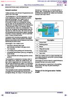
TIMING BELT Removal 1. Disconnect the battery negative cable. 2. Remove the parts in the numbered sequence
I. 2. 3. 4.
Engine side cover A/C and P/S drive belt and pulley Alternator and alternator drive belt Water pump pulley
shown
5. 6. 7. 8.
in the figure
Crankshaft pulley and baffle plate Upper and lower timing belt cover Timing belt tensioner and spring Timing belt
Note
Remove the No.3 engine mount installation P/S pulley and the crankshaft pulley.
nuts and lower the engine to remove
A/C and
IA-11
1
A
ON-VEHICLE
MAINTENANCE
mark
(TIMING
-
BELT)
Before removing the timing belt, do the following: 1. Turn the crankshaft to align the matching mark of the camshaft pulley with the cylinder head and the cylinder head cover timing mark.
2. Mark the direction
of rotation
on the timing
belt,
Note The direction arrow is so the belt can be reinstalled in the same direction. 3. Remove
the timing
belt.
Caution Do not allow any oil or grease on the timing belt.
Inspection Damage, wear
Refering to page IA-49, 1. Timing belt 2. Timing belt tensioner 3. Timing belt pulley 4. Camshaft pulley
inspect the following
parts:
and spring
Installation 1. Be sure that the timing mark on the timing ley is aligned with the matching mark.
belt pul-
ON-VEHICLE
Cylinder
head
Matching
mark
MAINTENANCE
(TIMING
BELT)
i
A
2. Be sure that the matching mark on the camshaft pulley is aligned with the cylinder head cover matching mark. If it is not aligned, turn the camshaft to align.
3. Install the timing belt tensioner and spring. Temporarily secure it so the spring is fully extended.
4. Install the timing
belt.
Caution a)The timing belt must be reinstalled in the same direction of previous rotation if it is reused. b)Be Sure that there is no oil, grease, or dirt on the timing bett.
Note Remove
all spark plugs for easler rotation.
5. Turn the crankshaft twice in the direction of rotation. (Clockwise) 6. Check that the timing marks are correctly aligned. If not repeat the above-mentioned procedure. 7. Loosen the tensioner lock bolt and apply tension to the belt.
lA-13
IA
ON-VEHICLE
MAINTENANCE
(TIMING
BELT)
8. Tighten Tightening 19-26
the timing
belt tensioner
torque: N.m (1.9-2.6
to specification.
m-kg,
14-19
ft-lb)
9. Turn the crankshaft twice in the direction of rotation and check the matching marks for alignment.
IO. Measure the tension between the crankshaft pulley and the camshaft pulley. If the timing belt tension is not correct, temporarily secure tensioner lock bolt so the spring is fully extended and repeat steps 5-9 above or replace the tensioner spring. 9&N (1 Okg,22lb)
Timing belt deflection: 12-13 mm (0.47-0.51 in) I98 N (10 kg, 22 lb) Caution Be sure not to apply tension of the tensioner spring. 11. Install the lower and upper Tightening torque: 8-11 N.m (0.8-1.1 12. Install the spark Tightening 15-23
other
timing
m-kg,
than
belt cover.
69-95
torque: N.m (1.5-2.3
m-kg,
torque: 12-17 .75 m-kg, 109-I
14. Install the No.3
in-lb)
plugs. II-17
13. Install the baffle plate and the crankshaft Tightening (1.25-l
that
engine
Tightening ,torque: 60-85 N.m (6.1-8.7
ft-lb)
pulley.
N-m 62 in-lb)
mount
bracket.
m-kg,
44-63
ft-lb)
1.5. Install the drive belt and adjust the belt tension (refer to page l A--6). 16. Install the engine side cover. 17. Connect the battery negative cable. lA-14
ON-VEHICLE CYLINDER Removal -.-
Warning Release
MAINTENANCE
(CYLINDER
HEAD)
1
A
HEAD
the fuel
pressure
(Refer
to FUEL
1. Disconnect the battery negative cable. 2. Drain the coolant. 3. Remove the parts in the numbered sequence
1. Air cleaner assembly 2. Oil level gauge 3. Accelerator cable and cruise control cable 4. Fuel hoses 5. Heater hoses 6. Brake vacuum hose 7. Canister hose 8. Engine harness connectors
9. IO. 11. 12.
PRESSURE
shown
RELEASE
of FUEL
SYSTEM
section).
in the figure
High-tension leads Distributor Spark plugs Engine hanger and ground wire 13. Upper radiator hose 14. Water bypass hose and bracket 15. Intake manifold assembly
16. 17. 18. 19. 20. 21. 22. 23. 24. 25.
Exhaust manifold insulator Exhaust manifold Water pump pulley Upper timing belt cover Timing belt Cylinder head cover Camshaft pulley Cylinder head bolts Cylinder head Thermostat assembly
lA-15
IA
ON-VEHICLE
MAINTENANCE
(CYLINDER -l
HEAD)
Fuel hose After disconnecting plug them.
Timing
the inlet and return
fuel hoses,
belt
1. Before removal of timing belt, turn the crankshaft to align the matching mark on the camshaft pulley with the matching mark on the cylinder head cover.
2. Loosen 3. Pull the row and 4. Remove
the timing belt tensioner lock bolt. tensioner in the direction indicated by artemporarily tighten the lock bolt. the timing belt.
Caution Do not allow any oil or grease on the timing belt.
5. Mark the forward direction
arrow on the timing
Note Direction arrow is for reassembling ing belt in the same direction.
belt.
the tim-
ON-VEHICLE
MAINTENANCE Camshaft
(CYLINDER
HEAD)
1
A
pulley
1. Remove the cylinder head cover. 2. Hold the camshaft using a suitable cast hexagon. 3. Remove the camshaft pulley.
Disassembly
of Cylinder
Refer to page
l A-32
wrench
on the
Head
Inspection Refer to page
IA-37
Assembly Refer to page
l A--59
Installation I. Thoroughly remove all dirt and grease from the top of the cylinder block with a rag. 2. Place the new cylinder head gasket in position.
1
3. Install the cylinder head, and tighten the cylinder head bolts gradually in the order shown in the figure.
Tightening torque: 75-81 N.m (7.7-8.3
m-kg, 56-60
ft-lb)
lA--17
IA
ON-VEHICLE
Dowel
MAINTENANCE
(CYLINDER
HEAD1
4. Install the camshaft pulley onto the dowell pin and keyway with the matching mark straight up, so that the timing marks on the camshaft pulley and cylinder head align.
pin and pin groove
Tightening 49-61
83”01A-Oi
torque: N.m (5.0-6.2
m-kg,
36-45
ft-lb)
!8
5. Apply a coat of sealant to the cylinder as shown in the figure.
head cover
PO-““;’
Sealr-+
6. Install the cylinder
head cover.
Tightening torque: 5-9 N,m (0.5-0.9
7. Install the timing
lA-18
m-kg,
43-78
belt (Refer to page
in-lb)
1 A-l
1)
ON-VEHICLE
MAINTENANCE
(CYLINDER
8. Install the upper
timing
Tightening torque: 8-l 1 Nm (0.8-l 9. install the water
.l m-kg, 69-96
pump
ground,
11. Install the exhaust
A
in-lb)
pulley.
m-kg, 69-95
front
Tightening torque: Front: 37-63 N.m (3.8-6.4 m-kg, 27-46 Rear: 19-30 N.m (1.9-3.1 m-kg, 14-22 4 a
1
belt cover.
Tightening torque: 8-11 N.m (0.6-1.1
IO. Install engine hanger.
HEAD)
and
rear
in-lb)
engine
ft-lb) ft-lb)
manifold.
Tightening torque: 16-23 N.m (1.6-2.3
m-kg, 12-17
ft-lb)
12. Install the exhaust manifold insulator. 13. Install the water bypass hose bracket. 14. install the intake manifold assembly.
Tightening torque: 19-26 N.m (1.9-2.6
15. Install the thermostat 16. Connect the upper
m-kg, 14-19
ft-lb)
assembly. (Refer to 1 A-66.) radiator hose.
Note Position the hose clamp in the original location on the hose and squeeze it lightly with large pliers to ensure a good fit.
IA-19
IA
ON-VEHICLE
MAINTENANCE “-*-hing
mark
(CYLINDER
HEAD)
17. Align the distributor blade with the small oil holes, then install the distributor by referring to Section 5. 18. Install the spark plugs.
--
Tightening torque: 15-23 Ndrn (1.5-2.3 19. Install the high-tension
m-kg, 11-17
ft-lb)
leads.
Y Y-83”01A~036 71
20. Install the engine harness 21, Install the canister hoses. 22. Install the ~vacuum hoses.
connectors.
23. 24. 25. 26.
Install the brake vacuum hose. Install the heater hoses. Install the fuel hose. Install the accelerator cable and cruise cable.
27. 28. 29. 30.
Install the oil level gauge. Install the air cleaner assembly. Fill the radiator with coolant. Perform the necessary engine adjustments ring to TUNEUP PROCEDURE section.
control
refer-
ON-VEHICLE VALVE
MAINTENANCE
(VALVE
SEAL)
1
A
SEAL
Removal
1. Disconnect the battery negative cable. 2. Remove each part in the numbered sequence
1, 2. 3. 4. 5.
Air intake pipe Upper timing belt cover bolt Cylinder head cover Rocker arm and rocker shaft assembly Thrust plate
Front
Rear
shown
6. 7. 8. 9. 10.
Rocker
in the figure.
Spring retainer Upper valve spring Valve spring Lower valve spring Valve seal
arm
and
rocker
seat seat
shaft
assembly
1. Remove the rocker arm and rocker shaft assembly.by gradually loosening the bolts in the order shown in the figure. 2. Plug the oil drain hole with a rag to prevent the spring retainer from falling into the oil pan.
lA--21
IA
ON-VEHICLE
MAINTENANCE
(VALVE
SEAL)
Valve seal 1. Remove the thrust plate. 2. Install the SST on the rocker arm shaft assembly installation hole.
3. Position the piston at top dead center 4. Remove the spring the SST. 5. Remove the valve and lower). 6. Remove the valve pliers or the SST
of the valve seal to be replaced by turning the crankshaft pulley. retainer by pressing down on spring and spring
seats (upper
seal from the valve guide
(49 320
with
170).
Installation 1. Apply a coat of engine oil to the inner surface the new valve seal. 2. Push it on gently, with the SST.
3. Install
the valve spring
Note Install the valve spring with its narrow end toward the cylinder head.
Cylinder
1A-22
head side
of
pitch
ON-VEHICLE
MAINTENANCE
(VALVE
SEAL)
1
A
4. Install the spring retainer with the SST (49 8012 OAO), and lightly tap the end to confirm correct assem bly.
5. Install the thrust
plate.
Tightening torque: 8-11 N.m (0.8-1.1
Front
Rear
m-kg, 69-96
in-lb)
6. Install the rocker arm and rocker shaft assembly on the cylinder head and tighten it gradually in the order shown in the figure.
Note Use the installation installing.
bolts for alignment
Tightening torque: 22-28 N.m (2.2-2.9
m-kg, 16-21
7. Apply a coat of sealant to the cylinder as shown in the figure. 8. Install the cylinder head cover.
Tightening torque: 5-9 N.m (OS-O.9
m-kg, 43-78
when
ft-lb)
head cover
in-lb)
l A-23
1
A
ON-VEHICLE
MAINTENANCE
(VALVE 9.
Install
SEAL) the upper
timing
Tightening torque: 8-11 N.m (0.8-1.1 10. Install
lA-24
the air intake
belt cover m-kg,
pipe.
bolt.
69-95
in-lb)
REMOVAL REMOVAL
AND
i
A
INSTALLATION
Warnig Release the fuel pressure
(Refer to FUEL PRESSURE RELEASE of FUEL SYSTEM section).
Disconnect the battery negative cable. Drain the engine oil, transaxle oil and coolant. Remove the parts in the numbered sequence Install in the reverse order of removal.
1. 2. 3. 4.
AND INSTALLATION
Battery and battery carrier Air cleaner assembly Oil level gauge Cooling fan and radiator assembly 5. Accelerator cable and cruise control cable (if equiped) 6. Speedometer cable
7. 8. 9. IO. 11. 12. 13. 14.
shown
below.
Fuel hoses Heater hoses Brake vacuum hose 3-way solenoid valve hoses Canister hose Engine harness connectors Engine ground Upper and lower radiator hose 15. Exhaust pipe
16. A/C compressor (if equipped) 17. P/S oil pump (if equipped) 18. Driveshafts 19. Clutch control cable (MTX) 20. Shift control rod (MTX) or shift control cable (ATX) 21. Under cover 22. Side cover 23. Engine mount 1A-25
IA
REMOVAL
AND INSTALLATION Fuel Hose After disconnecting the fuel hoses (inlet and return), plug them to avoid fuel leakage. -
A/C Compressor Remove the compressor, pressure and low-pressure it, secure the compressor
and then, with the highhoses still connected to as shown in the figure.
PIS Pump
Secure the P/S pump as shown in the figure. Be careful not to damage the pipe when the engine is removed and installed.
Hose Clamp
~.: :. ~ ..o ;; lA-26
1. Position the hose clamp in the original location on the hose. 2. Squeeze the clamp lightly with large pliers to ensure a good fit.
REMOVAL Engine Mount Torque
Specification
After installing
into the engine
the engine
room, tighten
the engine
AND INSTALLATION
mount
bolts to the specified
1
A
torque.
Steps After Installation 1, 2. 3. 4.
Adjust Fill the Fill the Fill the
the drive belt tension. (Refer to IA-6) radiator and sub tank with coolant. engine with engine oil. transaxle with transaxle oil.
Check Engine Condition 1. 2. 3. 4.
Check for leaks. Perform engine adjustment as necessary. Perform a road test. Recheck the oil and coolant levels.
lA-27
IA
DISASSEMBLY
DISASSEMBLY Disassembly Note 1. Care should be taken during the disassembly of any part or system to study its order of assembly. Any deformation, wear, or damage also should be noted. 2. Code all identical parts (such as pistons, piston rings, connecting rods, and valve springs) so that they can be reinstalled in the position from which they were removed. 3. After steam cleaning the parts, use compressed air to blow off any remaining water. 4. Remove the parts in the order shown in the figure. Disassemblv
IA-28
of Ermine
Auxiliarv
Parts
DISASSEMBLY 1. 2. 3. 4. 5. 6.
Engine mount and engine bracket A/C compressor bracket P/S pump bracket Alternator Coolant bypass pipe and hose Thermostat cover and thermostat
1
A
7. Exhaust manifold and gasket 8. High-tension leads, spark plugs and dis tributor 9. Intake manifold assembly and gasket 10. Oil filter 11. Oil pressure switch
Engine hanger After removing the exhaust gine on the SST.
manifold,
install the en-
lA-29
IA
DISASSEMBLY
Disassembly
of front of Engine
1 .Waterpump pulley 2 .Crankshaft pulley and baffle plate 3, Upper timing belt cover 4. Lower timing belt cover
IA-30
5. 6. 7. 8.
Timing belt tensioner and spring Timing belt Timing belt pulley Water pump and coolant inlet pipe
DISASSEMBLY
Aark the jirection of
rotation
Timing
A
i
belt
1. Remove tensioner 2. Mark the 3. Remove
the tensioner spring lock bolt. direction of rotation the timing belt.
after loosening
the
on the timing
belt.
Caution Do not allow any oil or grease on the timing belt.
Crankshaft
pulley and timing belt pulley
Set the SST to the flywheel. Remove pulley and the timing belt pulley.
the crankshaft
1 A-31
IA
DISASSEMBLY
Disassembly
Related
to Cylinder
Note During disassembly, ring to INSPECTION
1 .Cylinder head cover 2. Rocker arm and rocker 3 .Thrust plate 4 .Camshafl pulley 5 .Camshaft 6 .Cylinder head bolts 7 .Cylinder head 1 A-32
Head
inspect the camshaft AND REPAIR section
shaft assembly
end play,
8. 9. 10. 11. 12. 13. 14.
camshaft
bearing
Spring retainers Upper spring seats Valve springs Lower spring seats Valves Valve seals Cylinder head gasket
oil clearance
refer-
DISASSEMBLY
Front Q
Rear
1 A
Rocker arm and rocker shaft assembly 1. Loosen the bolts gradually in the sequence shown in the figure. 2. Remove the rocker arm and rocker shaft assembly with bolts.
Caution Do not mix up the various parts of the rocker arm and rocker shaft assembly.
Camshaft
pulley
1. Hold the camshaft using a suitable cast hexagon. 2. Remove the camshaft pulley.
Cylinder Front
Rear
wrench
on the
head bolt
Remove the cylinder head bolts in the numbered der shown in the figure. Loosen them gradually, order.
orin
Valve Remove SST.
the valves
from the cylinder
head with the
1 A-33
IA
DISASSEMBLY
Disassembly
.Clutch
Related to Lubrication
System and Flywheel
cover (MTX), Backing plate (ATX) disc IMTXI. Drive alate CATXl ’ 3. Flywheel (Mix), Adaptor ‘(ATX)‘ 4. End plate : .Clutch
5. 6. 7. 8.
Oil pan Oil strainer Rear cover Oil pump
Clutch cover and flywheel Remove the clutch cover and flywheel as shown in the figure.
1A-34
with the SST
DISASSEMBLY Disassembly
Related
to Crankshaft
and
1
A
Piston
Note During disassembly, inspect the crankshaft end play, main journal bearing oil clearance, connecting rod bearing oil clearance, connecting rod side clearance referring to ASSEMBLY section.
1. 2. 3. 4.
Connecting Connecting Connecting Piston rings
rod caps rod bearings rod and piston
pin
5. 6. 7. 8.
Main bearmg caps Crankshaft Main bearings Cylinder block
1 A-35
IA
DISASSEMBLY Piston
and
connecting
rod
1, Check the oscillation torque of the connecting rod as shown in the figue. If the large end does not drop by its own weight, replace the piston and/or piston pin.
r0 remove
2. Remove
Flywheel
the piston
pilot
pin with
the SST
as shown.
bearing
Use suitable pipe and punch out to the crankshaft side of the flywheel, as shown in the figure.
l A-36
INSPECTION INSPECTION
AND REPAIR
1
A
AND REPAIR
1. Clean all parts, taking care to remove any gasket residue, or other foreign material. 2. Inspect and repair in the order specified Caution Be careful not to damage as the cylinder head &
the ioints pistcns.
fragments,
or friction
surfaces
dirt, oil or grease,
of aluminum
alloy
carbon,
moisture
components
such
Cylinder Head 1, Inspect the cylinder head for damage, cracks, and leakage of water or oil, replace if necessary. 2. Measure the cylinder head distortion in the six directions shown in the figure. Distortion:
3. If the tion, If the tion,
0.15
mm
(0.006
in) max.
cylinder head distortion exceeds specificagrind the cylinder head surface. cylinder head height is not within specificareplace it.
Height: 107.4-107.6 Grinding:
0.20
Note Before grinding the following
mm mm
(4.226-4.236 (0.006
in)
in) max.
the cylinder head, first check Andy replace the head if
necessary. l
Sinking of valve seat Distortion of manifold
l
Camshaft oil clearance and end play
l
contact
surface
4. Measure the manifold contact surface distortion the six directions shown in the figure. IN
in
Distortion: 0.15 mm (0.006 in) max. 5. If distortion exceeds specification, grind face or replace the cylinder head.
the sur-
EX
lA-37
IA
INSPECTION
AND REPAIR Valve and Valve Guide 1. Inspect each valve for the following, replace or resurface as necessary. (1) Damaged or bent stem (2) Roughness or damage to the face (3) Damage or uneven wear of the stem tip 2. Check the valve head margin thickness, replace if necessary Margin thickness IN : 0.5 mm (0.020 EX: 1.0 mm (0.039
Valve face
Margin
thickness
3. Measure
the valve
Length IN : 103.77 EX: 102.67 4. Measure
mm mm
length. (4.0854 (4.0421
Valve g
l A--38
mm mm
(0.2744-0.2750 (0.2742-0.2748
in) in)
inner diameter. (0.2760-0.2768 (0.2760-0.2768
in) in)
6. Measure the valve stem to guide clearance (1) Method No. 1 Subtract the valve stem measurement from the corresponding valve guide inner diameter measurement. ~
Valve stem
mm mm
the valve guide
Inner diameter IN : 7.01-7.03 EX: 7.01-7.03
I-l-
in) in)
the valve stem diameter.
Diameter IN : 8.970-6.985 EX: 6.965-6.980
5. Measure
in) min. in) min.
I
INSPECTION
AND
REPAIR
i
A
(2) Method No. 2 Measure the valve stem play at a point close to the valve guide with the valve lifted off the valve seat.
Clearance IN : 0.025-0.060 mm (0.0010-0.0024 EX: 0.030-0.066 mm (0.0012-0.0026 Maximum: 0.20 mm (0.0079 in) 7. If the clearance exceeds the maximum, valve and/or valve guide.
Replacement
in) in)
replace
the
of valve guide
Removal 1. Gradually heat the cylinder prox. 90°C (IgOOF).
head
in water to ap-
2. Remove the valve guide from the side opposite combustion chamber with the SST. 3. Remove the valve guide clip
the
Installation 1. Fit the clip onto the valve guide. 2. Gradually heat the cylinder head in water to approx. 90°C (IgOOF). 3. Tap the valve guide in from the side opposite the combustion chamber until theclip contacts the cylinder head with the SST (49 0249 OlOA).
lA-39
IA
INSPECTION
AND REPAIR 4. Check that the protusion height the figure) is within specification.
Height: 13.2-13.8
mm (0.520-0.543
(dimension
A in
in)
Note Although the shapes of the intake and exhaust valve guides are different, use the exhaust valve guide on both sides as a replacement.
Valve Seat 1. Inspect the contact surface of the valve seat and valve face. (1) Rouahness (2) Damage 2. If necessary, resurface the valve seat using a 45O valve seat cutter and/or resurface the valve face.
3. Apply a thin coat of prussian blue to the valve face. 4. Check the valve seating by pressing the valve against the seat. (1) If blue does not appear 360° around the valve face, replace the valve. (2) If blue does not appear 360° around the valve seat, resurface the seat.
INSPECTION
AND
REPAIR
1
5. Check the seat contact width and valve seating sition on the valve face.
Width: 1 .1-l Seat contact
.7 mm (0.043-0.067
6. Check that the valve seating ter of the valve face.
A po-
in) position
is at the cen-
(1) If the seating position is too high, correct the valve seat using a 7.5O cutter, and a 45O cutter. (2) If the seating position is too low, correct the valve seat using a 35O (IN) or l5“ (EX), and a 45O cutter. 7. Seat the valve to the valve seat using a lapping compound.
EX
IN
8. Check the sinking Measure protruding valve stem.
of the valve seat. length (dimension
“L”) of the
Dimension “L”: 39.0 mm (1.535 in) (1) If “L” is as below, it can be used as it is 39.0-39.5 mm (1.535-l .555 in) (2) If “L” is as below, insert a spacer between the spring seat and cylinder head so that “L” will be as specified.
39.5-40.5 mm (1.555-l ,594 in) (3) If “L” is more than as below, replace the cylinder
head.
40.5
mm (1.594 in) or more
Valve Spring 1, Inspect each valve spring for cracks or damage. 2. Check the free length and angle, replace if necessary.
Free length Standard: Minimum:
43.7 mm (1.720 in) 42.3 mm (1.665 in)
1 A-41
IA
INSPECTION
AND REPAIR Angle:
1.5 mm (0.059 in) max.
Camshaft 1. Set the front and rear journals on V-blocks. Check the camshaft runout, replace if necessary.
Runout:
83WlA-07
0.03 mm (0.0012 in) max.
4
2. Check the cam for wear or damage, replace if necessary. 3. Check the cam lobe height at the two places as shown.
Height IN : 36.38-38.53 mm (1.432-1.438 in) EX: 36.38-36.53 mm (1.432-l .438 in) Minimum IN : 36.23 mm (1.426 in) EX: 36.23 mm (1.426 in)
4. Measure wear of the journals at the two places shown,
in X and Y directions
Diameter Front and rear: 43.440-43.465
Center: 43.410-43.435 Out-of-round:
mm (1.7102-l
.7112 in)
mm (1.7091-1.7100
0.05 mm (0.002 in) max.
in)
INSPECTION
AND
REPAIR
1
A
5. Measure the oil clearances between the camshaft and cylinder head. (1) Remove any oil or dirt from the journals and the camshaft bore. (2) Measure the camshaft bore diameter.
Diameter: 43.500-43.525
(3) Subtract ameter.
mm (1.7126-l
the journal
diameter
.7135 in)
from the bore di-
Oil clearance Front and Rear 0.035-0.085 mm (0.0013-0.0033 Center: 0.065-0.115 mm (0.0026-0.0045 Maximum: 0.15 mm (0.0059 in)
in) in)
(4) If the clearance exceeds the maximum, the camshaft or cylinder head.
replace 83U01A~078
6. Measure the camshaft end play. If it exceeds the maximum, replace the thrust plate or camshaft
End play: 0.0.5-0.18 mm (0.0020-0.0071 Maximum: 0.20 mm (0.0079 in)
in)
Rocker Arm and Rocker Arm Shaft 1. Check for wear or damage to the contact surface of the rocker arm shaft or the rocker arm. Replace if necessary. 2. Check the oil clearance between the rocker arm and shaft, replace if necessary. (1) Measure the rocker arm inner diameter.
Diameter: 18.000-18.027
mm (0.7087-0.7097
in)
1 A-43
IA
INSPECTION \
AND
REPAIR (2) Measure
the rocker
Diameter: 17.959-17.980
mm
arm shaft diameter (0.7070-0.7078
(3) Subtract the shaft diameter diameter. Oil clearance: 0.020-0.068 Maximum: 0.10
in)
from the rocker arm
mm (0.0008-0.0027 mm (0.0039 in)
Hydraulic Lash Adjuster (HLA) Check the HLA face for wear or damage, necessary.
in)
replace
Caution Do not remove the HLA unless necessary prevent damage to the “0” ring.
if
to
Cylinder l3lock 1. Check the cylinder block, repair or replace if necessary. (1) Leakage damage (2) Cracks (3) Scoring of wall 2. Measure the distortion of the top surface of the cylinder block in the six directions shown in figure. Distortion:
0.15
mm
(0.006
in) max.
3. if the distortion exceeds the maximum, repair grinding, or replace the cylinder block. Grinding:
IA-44
0.20
mm (0.008
in) max.
by
INSPECTION
AND
REPAIR
1
A
4. Measure the cylinder bore in directions X and Y at three levels in each cylinder as shown,
Cylinder
bore
I
Size
0.50 (0.020)
mm (in) I
oversize
Bore
I
78.500-78.519 (3.0905-3.0913)
(1) if the difference between the measurement A and C exceeds the maximum taper, rebore the cylinder to oversize.
Taper: 0.019 mm (0.0007
in) max.
(2) If the difference between the measurement and Y exceeds the maximum out-of-round, bore the cylinder to oversize.
Out-of-round: Caution The boring cylinders.
X re-
0.019 mm (0.0007 in) max. size should
be the same for ail
5. If the upper part of the cylinder wall shows uneven wear, remove the ridge using a ridge reamer.
1 A-45
PiStOIl
1. Inspect the outer circumferences of all pistons for seizure or scoring, replace if necessary. 2. Measure the outer diameter of each piston at a right angle (WY) to the piston pin, 16.5 mm (0.650 in) below the oil ring land lower edge. Piston
diameter
I
mm (in)
Sire
/ 0.50 (0.020) oversize
3. Check
Diameter
I
the piston
I
I c%E
to cylinder
clearance
Clearance: 0.026-0.065
Maximum:
0.15
mm mm
(0.0010-0.0026 (0.0059 in)
in)
4. If the clearance exceeds the maximum, replace the piston or rebore the cylinder to oversize. Note If the piston rings also.
is replaced,
replace
the
piston
Piston and Piston Ring 1. Measure the piston ring to ring land clearance around the entire circumference using a new piston ring. Clearance
(Top
0.030~-0.065
Maximum:
0.16
2. If the clearance piston.
and Second): mm (0.0012-0.0026 mm (0.006 in)
exceeds the maximum,
3. Inspect the piston wear, or breakage, 4. Insert the piston ring push it to the bttom piston.
IA-46
in) replace the
rings for damage, abnormal replace if necessary into the cylinder by hand and of the ring travel in using the
INSPECTION
AND
REPAIR
1
5. Measure each piston ring end gap using gauge, replace if necessary.
A
a feeler
End gap : 0.20-0.40 mm (0.008-0.016 TOP Second: 0.15-0.30 mm (0.006-0.012 Oil rail : 0.20-0.70 mm (0.006-0.028 Maximum: 1.0 mm (0.039 in)
Piston and Piston Pin 1. Measure the piston pin hole diameter directions at four places. Diameter: 19.988-20.000 2. Measure manner.
the
mm piston
3. Check
the piston
Clearance: 0.008-0.026
in X and Y
(0.7869-0.7874
pin diameter
Diameter: 19.974-19.980
mm
in the same
(0.0003-0.0010
Rod the connecting
Diameter: 19.948-19.961
2. Check the interference bore and piston pin. Interference: 0.013-0.032
rod small
mm
mm
in)
clearance. in)
4. If the clearance exceeds the maximum, piston and/or piston pin.
Connecting I. Measure
in)
(0.7884-0.7866
pin to piston mm
in) inj in)
replace the
end bore
(0.7854-0.7859 between
(0.0005-0.0013
in)
the small
end
in)
lA-47
IA
INSPECTION
AND REPAIR 3. Check each connecting rod for bending or twisting, if necessary replace or repair. Bend: 0.04 mm (0.0016 in) max. Twist: 0.04 mm (0.0016 in) max.
Crankshaft 1, Checkthe journals and pins for damage, scoring, or oil hole clogging. 2. Set the crankshaft on V-blocks. 3. Check the crankshaft runout at the center journal, replace if necessary. Runout:
0.04 mm (0.0016
in) max.
4. Measure each journal diameter in X and Y direc, tions at two places. Main journal Diameter: 49.936-49.966 mm (1.9661-l .9668 in) Minimum: 49.89 mm (1.964 in) Out-of-round: 0.05 mm (0.0020 in) max. Crankpin journal Diameter: 44.940-44.956 mm (1.7693-l .7699 in) Minimum: 44.89 mm (1.7673 in) Out-of-round: 0.05 mm (0.0020 in) max. 1 A-48
INSPECTION 5. If the diameter Crankpin
AND
is below
the minimum,
1 grind
A the
journals to match undersize bearings. Undersize bearing: 0.25 mm (0.010 Main
journal
Crankpin
journal
Bearing size 0.25 undersize 0.50 undersize
Caution Do not grind
in), 0.50
diameter
Main journal
Vet
REPAIR
) 1 1
the
mm
(0.020
undersize
in) mm (in)
49.688-49.706
(1.9562-l
49.438-49.456
(1.9464-1.9471)
diameter
undersize
Journal 44.690-44.706 44.440-44.456
fillet
.9569)
mm (in)
diameter (1.7594-1.7601) (1.7496-1.7502)
roll.
R
Main Bearing and Connecting Rod Bearing Check the main bearings and the connecting rod bearings for peeling, scoring, or other damage.
Damage, wear
Timing Belt 1. Replace the timing belt if there is any oil or grease on it. 2. Check the timing belt for damage, wear, peeling, cracks, or hardening, replace if necessary.
lA-49
IA
INSPECTION
AND REPAIR Caution a) Never forcefully twist the timing belt. Do not turn it inside out or bend it. b) Be careful not to allow oil or grease on the
Q&F 25mm
(1 .Oin)
x
liming Belt Tensioner and Idler Pulley Check the timing belt tensioner and idler pulley for smooth rotation or abnormal noise, replace if necessary. Caution Do not clean the tensioner with cleaning fluids. If necessary, use a soft rag to wipe it clean, and avoid scratching it.
Timing Belt Tensioner Spring Check the free length of the tensioner if necessary. Free length: 64.0 mm
(2.520
spring,
replace
in)
Timing Belt Pulley and Camshaft Pulley Inspect the pulley teeth for wear, deformation, or other damage, replace the pulley if necessary. Caution Do not clean If necessary, Timing Inspect cracks,
l A-50
the pulley with cleaning fluids. use a rag to wipe it clean.
Belt Cover (lower and upper) the timing belt covers for deformation replace if necessary.
of
1’
ASSEMBLY
1 A
ASSEMBLY Assembly Note 1. Be sure ail parts are clean before reinstallation. 2. Apply new engine oil to all sliding and rotating parts. 3. Do not reuse gaskets or oil seals 4. During assembly, inspect all critical clearances, end plays 5. Tighten bolts to the specified torques. 6. Replace bearings if they are peeling, burned, or otherwise
and oil clearances damaged.
Connecting Rod 1, Align the oil groove in the large end of the connecting rod opposite the “F” mark on the piston. 2. Apply a coat of engine oil to the circumference of each piston pin and to the small end of each connecting rod.
To press in Piston . pin R
m
:
8,’ n
3. Set the SST in position as shown in the figure. 4. Insert the piston pin from the direction of the “F” mark on the piston. 5. Press the upper part of the SST (49 8134 042) with a press to force in the piston pin. 6. The piston pin shouid go in until the lower end of the SST (49 8134 044) meets the bottom of the SST (49 8134 041A). Pressure (500-l
force: 4.9-14.7 kN ,500 kg, 1 ,lOO-3,300
Ib)
7. If the piston pin cannot be pressed in within specified pressures, replace the piston pin or connecting rod. 8. Check the oscillation torque of the connecting as shown in the figure. If the large end does drop by its own weight, replace the piston and ton pin.
the the rod not pis-
IA-51
IA
ASSEMBLY Piston Ring 1. Install the (1) Apply (2) Install (3) Install
three-piece oil rings on the pistons. engine oil to the oil ring spacer and rails. the oil ring spacer. the upper rail and lower rail.
Caution a)After installation of the upper and lower side rails, make certain they turn smoothly in both directions. b)Do not align the end gaps, stagger them.
Oil ring
/-----IE
qbii
Oil ring (lower rail)1
w
Oil ring (spacer:
Oil ring (upper rail) Oil rina fsoacer) 2. Install the second and top ring. (1) Apply a liberal coat of engine oil to the piston rings. (2) Install the second ring to the piston first, then the top one, using a piston ring insertion tool, (commercially available). Caution The rings must face upward.
Compression
ring
Compression
ring (No.2) Compression ring (No.1) ~ Compression ring (No.2) ~
lA--52
1
be installed
(3) Position the opening the figure.
so the “R”
marks
of each ring as shown in
ASSEMBLY Crankshaft 1. Inspect the oil clearances main bearings.
A
1
of the crankshaft
Caution The main bearing with the oil grooves be installed in the cylinder block.
and
must
(1) Remove any foreign material and oil from the journal and bearing. (2) Install the main bearings and the crankshaft. (3) Position the plasti-gauge on top of each journal (in the journal axial direction), away from the oil hole.
(4) Set the main bearing caps according number and m mark, and trghten Note Do not rotate the crankshaft the oil clearances. Tightening 54-59
63”OlX-09
torque: N.m (5.5-6.0
when
m-kg,
to the cap it. measuring
40-43
ft-lb)
(5) Remove the main bearing cap, and measure the plasti-gauge at each journal at the widest point for the smallest clearance, and at the narrowest point for the largest clearance. Oil clearance: 0.024-0.042 mm (0.0009-0.0017 Maximum: 0.10 mm (0.0039 in)
in)
(6) If the oil clearance exceeds the limit, grind the crankshaft and use undersize main bearings.
.33”01A-1C
Undersize main bearings: 0.25 mm (0.010 in), 0.50
mm
(0.020
in) 1 A-53
IA
ASSEMBLY 2. Apply engine oil to the main bearings and main journals, 3. Install the thrust bearings to the cylinder block side. 4. Install the crankshaft, and install the main bearing caps according to the cap number and mmark.
5. Inspect
crankshaft
end play
End play: 0.08-0.282 mm (0.0031-0.0111 Maximum: 0.30 mm (0.012 in)
If end play exceeds thrust bearings.
in)
the limit, adjust the end play with
Standard thickness: 2.50-2.55 mm (0.0984-0.1004 in) Undersize width: 0.25 mm (0.010 in): 2.625-2.675 mm (0.1033-0.1053 in) 0.50 mm (0.020 in): 2.750-2.600 mm (0.1083-0.1102 in) Note Oil groove of the thrust bearing must face the crankshaft. Piston and Connecting
Rod Assembly
1. Apply engine oil to the cylinder wails, piston circumference, and rings. 2. Insert each piston and connecting rod into the cylinder block by using a piston insertion tool, (commercially available).
Caution The pistons must be inserted so that the “F” marks face the front of the cylinder block.
IA-54
ASSEMBLY
i a
Connecting Rod Cap 1. Inspect and adjust the connecting rod bearing and crankshaft pin journal oil clearance by the same procedure used for the crankshaft and main bearing oil clearance. Connecting rod cap tightening torque: 47-52 N.m (4.8-5.3 m-kg, 35-38 ft-lb) Oil clearance: 0.028-0.088 mm (0.001 l-0.0027 in) Maximum: 0.10 mm (0.0038 in) Undersize connecting rod bearing: 8.25 mm (0.010 h), 0.50 mm (0.020 in) Caution Be sure to align the matching marks cap and on the connecting rod when ing the connecting rod cap.
2. Check
the side clearance
on the instail-
of the connecting
rod.
Clearance: 0.30 mm (0.012 in) max. Caution The connecting rod side clearancs measured before installation.
must
be
3. Apply engine oil to the crankpin journal and connecting rod bearing. 4. Install the connecting rod cap to align the matching mark and tighten it. Tightening 47-52
torque: N.m (4.8-5.3
m-kg,
35-38
ft-lb)
Rear Cover 1. Apply engine oil to the rear cover, oil seal and oil seal lip. 2. Press the oil seal into the rear cover.
1A-55
IA
ASSEMBLY
1
3. Install the rear cover
Tightening torque: S-11 N.m (0.8-1.1
along
with a new gasket.
m-kg, 69-95
4. Cut away the part of the gasket from the rear cover assembly.
in-lb)
that projects
out
Caution Do not scratch the rear cover assembly.
End Plate Install the end plate
Tightening torque: S-11 N.m (0.8-1.1
m-kg, 69-95
in-lb)
Oil Pump 1, Remove any dirt or grease from the contact surfaces of the cylinder block and oil pump with a rag. 2. Apply engine oil to the oil seal lip. 3. Install new gasket.
Caution Do not allow any sealant in the oil hole.
ASSEMBLY
1
A
4. Install the oil pump.
Tightening torque: 19-26 N-m (1.9-2.6 5. Remove
any sealant
m-kg, 14-19
which
is squeezed
ft-lb) out
83U01A.1‘
I
r-v
Oil Strainer Install the oil strainer
along
Tightening torque: 8-11 N.m (0.8-1.1
with a new gasket.
m-kg, 69-95
in-lb)
Oil Pan 1. Apply sealant to the shaded areas as in the figure. 2. Install the oil pan along with the gasket and stifener.
Tightening torque: 8-9 N.m (0;6-0.9
m-kg, 52-76
in-lb)
lA--57
SA
ASSEMBLY Flywheel (MTX) 1. Tap the pilot bearing in with a suitable pipe and ,hammer. 2. Apply sealant to the flywheel bolts. Caution If reinstalling flywheel bolts, clean threads to remove old sealant, apply new sealant and tighten to speclficatlon. If old sealant can not be removed, replace bolts. 3. install the flywheel, with the SST while tightening. Tightening 96-103
torque: N*m (9.6-10.6
m-kg, 71-76
ft-lb)
Drive Plate (ATX) Install the drive plate along with the adapter and backing plate with the SST. Tightening 96-103
torque: N.m (9.6-10.6
m-kg, 71-76
ft-lb)
Clutch Disc and Clutch Cover Install the clutch disc and clutch cover with the SST, and tighten the clutch cover. Tightening torque: 18-26 N*m (1.8-2.7
m-kg, 13-20
Note Follow the clutch disc Installation exactly (See Section 6).
ft-lb)
directions
Valve Seal 1. Apply engine oil to the inner surface of the new valve seal. 2. Install the valve seal onto the valve guide with the SST.
IA-58
323 Revised 10187
._~,Y
Valve and 1. install the 2. Install the 3. Install the
Valve spring
Note Install toward
Cylinder
Valve Spring lower spring seat. valve. valve spring and the upper
the spring with its narrow the cylinder head.
spring
seat.
pitch
end
head side 63UO1X-09 4. Install the spring retainer after compressing valve spring with the SST.
the
Cylinder Head 1. Thoroughly remove all dirt and grease from the top of the cylinder block with a rag. 2. Place the new cylinder head gasket in position.
3. Install the cylinder Tightening 76-81 Caution Tightening and in the
head
torque: N.m (7.7-6.3
m-kg,
56-60
ft-lb)
the bolts must be done gradually order shown in the flgure.
lA-59
1 A
ASSEMBLY Camshaft Oil Seal 1. Apply a thin coat of engine oil to the camshaft oil seal and cylinder head. 2. Tap the camshaft oil seal into the cylinder head.
3
Camshaft Apply engine oil to the journals and bearings, then insert the camshaft in position with the thrust plate. Tightening torque: 8-111 N-m (0.8-1.1
m-kg, 69-95
in-lb)
J 1
Dowel
Camshaft Pulley 1. Install the camshaft pulley onto the dowell pin with the pin groove facing straight upward.
pin and pin groove
Note Be certain that the dowel pin of the camshaft also faces straight upward.
63lmX-12
1
2. Tighten the camshaft pulley bolt. Hold the camshaft using a suitable wrench on the cast hexagon, as shown. Tightening torque: 49-61 N.m (6.0-8.2
!2
m-kg, 38-45
ft-lb)
.-,
ASSEMBLY
i A
Hydraulic Lash Adjuster (HLA) 1. Pour engine oil into the oil reservoir in the rocker arm. 2. Apply engine oil to the new HLA. 3. Install the HLA in the rocker arm. Caution a) Do not remove the HLA from the rocker arm unless necessary. b)Be careful not to damage the O-ring when installing.
Rocker Arm and Rocker Shaft Assembly 1. Assemble the rocker arm and rocker shaft assembly as shown in the figure. No.4 cylinder
No.1 cylinder
Intake
xhaust
No.1 cylinder Intake I 0 =‘, w
No.4 cylinder A 0
0 r
I-“1
Exh:ust
idb
Caution a) Be sure both rocker arm shaft oil holes face downward. b) The installation bolt holes are different for the exhaust and intake sides as shown in the figure.
r,
Note There are two types of rocker arms with different offsets. The rocker arms used for No. 1 and No. 2 cylinder are the same for exhaust and intake. No. 3 and No. 4 also use the same rockers.
No.1, 2 cylinder (IN & EX)
1A-61
IA
ASSEMBLY 2. install the rocker arm and rocker shaft assembly. Caution The bolts must be tightened order shown in the figure. Tightening 22-28
Cylinder
torque: N.m (2.2-2.9
Head
evenly
m-kg,
18-21
and in the
ft-lb)
Cover
1. Apply a coat of sealant in the groove as shown. 2. Place the gasket in position.
3. Install the cylinder head cover with new seal washers. Tightening torque: 5-9 N.m (0.5-0.9
m-kg,
43-78
in-lb)
4. Install the filler cap and the ventilation hose.
Water
Pump
1. Remove any dirt or old gasket from the water pump mounting surface. 2. Place a new water pump gasket in position.
ASSEMBLY 3. Install the water Tightening 19-26
1
A
pump.
torque: N.m (1.9-2.6
m-kg,
14--19
ft-lb)
Timing Belt Pulley 1, Reverse the direction of the (49 E301 060). 2. Install the timing belt pulley and key. 3. Apply sealant to the timing belt pulley bolt then tighten it. Tightening 106-126 ft-lb)
torque: N.m (11.0-13.0
m-kg,
80-94
4. Release the SST (49 E301 060). 5. Turn the crankshaft so that the timing mark on the oil pump body is aligned with the groove.
atching
mark
Tlming Belt Tensioner 1, Install the timing belt tensioner. 2. Install the tensioner spring. 3. Temporarily secure the tensioner fully extended.
so the spring
1 A-63
is
IA
ASSEMBLY Timing
Belt
1. Be sure that the timing mark on the cylinder head and the timing mark on the camshaft pulley are aligned.
2. Install
the timing
belt.
Caution a) The timing belt must be reinstalled in the direction of previous rotation if it is reused. b) Be sure that there is no oil, grease, or dirt on the timing belt.
side
3. Turn the crankshaft twice in the direction of rotation. (Clockwise) 4. Check that the timing marks are correctly aligned. If not repeat the above-mentioned procedure. 5. Loosen the tensioner lock bolt and apply tension to the belt.
6. Tighten
the timing
belt tensioner
Tightening torque: 19-26 N.m (1.9-2.6
to specification.
m-kg, 14-19
ft-lb)
7. Turn the crankshaft twice in the direction of rotation and check the matching marks for alignment.
1 A-64
ASSEMBLY
1
A
8. Measure the tension between the crankshaft pulley and the camshaft pulley. If the timing belt tension is not correct, temporarily secure tensioner lock bolt so the spring is fully extended and repeat steps 3-7 above or replace the tensioner spring.
liming belt deflection: 12-13 mm (0.47-0.51 in)/98 N (10 kg, 22 lb)
Timing Belt Cover install the lower and upper timing gaskets.
Tightening torque: 8-11 N.m (0.8-1.1
Crankshaft
belt covers and new
m-kg, 69-95
in-lb)
Pulley
Install the crankshatt
pulley
and baffle plate.
Tightening torque: 12-17 N.m (1.25-1.75 m-kg, 109-152 in-lb)
Water Pump Pulley Install the water
pump
pulley.
Tlghtening torque: 8-11 N,m (0.8-1.1
m-kg, 69-95
In-lb)
Engine Bracket Install the engine
bracket.
Tightening torque: 93-l 13 N.m (9.5-l
1.5 m-kg, 69-83
ft-lb)
1 A-65
IA
ASSEMBLY Coolant Inlet Pipe Install the coolant inlet pipe and a new gasket. Tightening 19-26
torque: N.m (1.9-2.6
Coolant Bypass Hose 1, Apply a coat of vegetable 2. Install the coolant bypass Tightening 16-23
torque: N.m (1.6-2.3
m-kg,
14-19
ft-lb)
oil to the “0” hose.
ring.
m-kg,
ft-lb)
12-17
Thermostat and Thermostat Cover 1. Install the thermostat with the jiggle pin facing upward. 2. Install the thermostat cover and gasket Tightening 19-26 Caution The printed thermostat.
torque: N.m (1.9-2.6 side
Oil Pressure Switch &tall the oil pressure Tightening 12-18 (1.2-l
torque: N.m .8 m-kg,
m-kg,
of the gasket
14-19
ft-lb)
must
face the
switch
8.7-13.0
ft-lb)
Oil Filter Apply engine oil to the oil filter “0” ring and install the filter, tightening thoroughly by hand.
I 1 A-66
ASSEMBLY Matching
mark
Distributor 1. Apply engine oil to on the distributor. 2. Apply engine oil to 3. Install the distributor shaft groove. 4. Temporarily, loosely ing bolt.
the “0”
ring, and position
the drive gear. with the blade into the camtighten
the distributor
Spark Plug and High Tension 1. Install the spark plugs. Tightening 15-23 2. Connect
m-kg,
the high tension
leads.
torque: N.m (1.9-2.6
Tightening torque: Front: 37-63 N.m (3.8-6.4 m-kg, 27-46 Rear: 19-30 Nm (1.9-3.1 m-kg, 14-22
11-17
assembly
m-kg,
Engine Hanger Install the front and rear engine
install-
Lead
torque: N.m (1.5-2.3
intake Manifold Assembly 1, Install the Intake manrfold gasket. Tightening 19-26
1 A
14-19
ft-lb)
and
new
ft-lb)
hangers
ft-lb) ft-lb)
lA-67
it
IA
ASSEMBLY Exhaust Manifold 1. Remove the engine from the engine hanger engine stand. 2. Install the exhaust manifold and gasket.
Tightening torque: 16-23 N.m (1.6-2.3 3. Install the exhaust
m-kg, 12-17
manifold
Tightening torque: 6-l 1 N.m (0.8-1.1
and
ft-lb)
insulator.
m-kg, 69-95
in-lb)
Alternator 1. Install the alternator
strap
Tightening torque: 37-52 N.m (3.8-5.3
m-kg, 27-38
ft-lb)
2. Install the alternator and alternator drive belt. Loosely tighten the alternator installation bolt. 3. Adjust the drive belt deflection by referring to page 1 A-6.
Tightening torque: Alternator installation 37-52 N.m (3.8-5.3 Belt adjusting bolt: 19-28 N,m (1.9-2.6
f&lb)
m-kg, 14-19
ft-lb)
Power Steering
Pump Bracket
Install the power
steering
pump
Tightening torque: 47-86 N,rn (4.8-6.7 Air Conditioner
Tightening torque: 37-52 N,m (3.8-5.3
bracket.
m-kg, 35-48
Compressor
Install the air conditioner
lA-68
bolt: m-kg, 27-38
f&lb)
Bracket
compressor
bracket
m-kg, 27-38
ft.lb)
IB
ENGINE (B6 DOHC) OUTLINE . . . . . ..a....................................... STRUCTURAL VIEW . . . . . . . . . . . . . . . . . . . ,, . . . . . . . . . SPECIFICATIONS . . . . . . . . . . . . . . . . . .. . . . . . . . . . . .. .. . TROUBLESHOOTING GUIDE . . . . . . . . . , . . . . . . . . . TUNE-UP PROCEDURE .. . . . . . . .. . . . . . .. , . . . . . . . . . ON-VEHICLE MAINTENANCE .. . . . . . .. . . . . . . . . . . TIMING BELT........ . . . . . , .,..,.I.,..,............, CYLINDER HEAD . . . . . . . . . . . . . . . . . . . . . . . . . . . . . . . . . REMOVAL AND INSTALLATION . . .. .. . . . . . . . . DISASSEMBLY . .. .. . . . .. . . . .. . . .. . .. . . . . . .. . . . . . . . . . . INSPECTION AND REPAIR . . . . . . . . . . . . . . . . . . . . . . ASSEMBLY . . . . . . . . . . . . . . . . . . .. . . . . . .. . . . . . . . . . . . . . . . . .
lB2 IB2 3 IB1 B3 5 lBIB--11 78-11 18-15 18-22 1 B-26 1 B-36 1 B-51 wJ018.00,
16
OUTLINE
OUTLINE STRUCTURAL
VIEW
-_
18-Z
1 63UOlX.002
TROUBLESHOOTING
GUIDE
16
SPECIFICATIONS 66 DOHC
Tvtx
Gasoline, 4-cycle
Cylinder arrangement
and number
In-line 4.cylinders
I
Combustion chamber
Pent-roof
Valve system
OHC. belt-driven
Displacement
cc (cu in)
Bore and stroke
1,597 (97.4)
mm (in)
76 x 63.6 (3.07 x 3.29)
Compression ratio
7.9
Compression
kPa (kg/cm’, psi)-rpm
1,079 (11.O, 156) - 300
Open
BTDC
50
Close
ABDC
510
open
BBDC
69O
Close
BTDC
10
IN Valve timing EX
Valve Clearance
IN
0. maintenance-free
EX
0. maintenance-free
mm (in)
Idle speed (MTX in neutral) Ignition timing
mm
650 * 50
BTDC
120 * 10
Firing order
l-3-4-2 83”01BOO2
TROUBLESHOOTING
GUIDE
Problem Difficult
Poor
starting
idling
Excessive oil consumption
Possible Malfunction
Cause
of engine-related
Remedy
Page
Replace or repair
1B-37 1B-45 18-15
components
Burned valve Worn piston, piston ring, or cylinder Failed cylinder head gasket
ReplaCe
Malfunction
of fuel
Refer to Section 4B
Malfunction
of electrlcal
Malfunction
of engjne-related
ReplEC3
system
Refer to Section 5
system components
Malfunction of HLA Poor valve to valve seat contact Failed cylinder head gasket
Rl?pl&2e
Malfunction
of fuel system
Refer to Section 48
011 working
up
Repair or replace Replace
Worn piston ring groove or sticking piston ring Worn piston or cylinder
Replace Replace or repair
Oil working down worn Valve seal
R@XZ
Worn valve stem or guide
Replace
Oil leakage
Refer to Section 28
1B-60 1B-39
1B-45 1B-45 1B-59 1B-37 S3”018-003
323 Revised
10187
IB
TROUBLESHOOTING
GUIDE
Problem Insufficient
DOYter
Possible Insufficient
Cause
Remedy
Page
compression
Malfunction of HLA Compression leakage from valve seat Seized valve stem Weak or broken valve spring Failed cyl,inder head gasket Cracked or distorted cylinder head Sticking, damaged, or worn piston ring Cracked or worn piston
Replace Replace Replace Replace Replace Replace
MaltunctIon of fuel svstem
Refer to Section
1 B-60 1 B-39 1 B-37 I B-40 18-15 1 B-36 1 B-46 1 B-46
ReplaCe
Repair
48
Others Slipping clutch Dragging brakes Wrong size tires
Abnormal combustion
Refer to Section 6 Refer to Section 11 Refer to Section 12
Malfunction of engine-related components Malfunction of HLA Sticking or burned valve Weak or broken valve spring Carbon accumulation in combustion
Replace Replace Replace Eliminate
chamber
Malfunction of fuel system Engine noise
1B-60 1 B-37 1 B-40 -
carbon
Refer to Section
48
Crankshaft or bearing related parts Excessive main bearing oil clearance Main bearing seized or heat-damaged Excessive crankshaft end play Excessive connecting rod bearing oil clearance Connectina rod bearina seized or heat-damaaed
Replace Replace Replace Replace Replace
or repair
Replace Replace Replace
or repair
1 B-54 1 B-53 1 B-54 1 B-55 78-55
or repair or repair
Piston ralated parts Worn cylinder Worn piston or piston pin Seized piston Damaged piston ring Bent connectina rod
1 B-44 3-45, 41 1 B-45 1 B-46 1 B-47
Rl?pl.We
Replace
___~
Valves or timlng related parts Malfunction of HLA* Broken valve spring Excessive valve guide clearance Malfunction of timing belt tensioner
Replace Replace Replace
Malfunctlon of coolino svstem
Refer to Section 3B
Malfunction of fuel system
Refer to Section
1 B-60 1 B-40 1 B-37 1 B-49
Ftf3piC3
46
Others Malfunction of water pump bearing Improper drive-belt tension Malfunction of alternator bearing Exhaust gas leakage * Tappet noise may occur if the engine is not operated for an extended the engine has reached normal operating temperature.
Replace 4djust Replace Repair period
of time. The noise should
1 B-6 1 B-36 disappear
after
83”01E%OO4
1 B-4
TUNE-UP TUNE-UP
PROCEDURE
16
PROCEDURE
Tune the engine scribed below.
according
to the procedures
de-
5B”Cl1XJ206
Battery 1. Check the indicator sign on the top of the battery. If the indicator sign is blue, the battery is normal. 2. If the blue indicator sign is not visible, then the electrolyte level of the battery is low and/or the capacity is insufficient. 3. Add distilled water and/or recharge according to the procedures described in Section 5. 4. Check the tightness of the terminals to ensure good electrical connections. Clean the terminals and coat the terminals with grease. 5. Inspect for corroded or frayed battery cables. 6. Check the rubber protector on the positive terminal for proper coverage.
Air Cleaner
Element
Visually check that the air cleaner element for excessive dirt, damage or oil. Replace if necessary
Caution Do not clean the air cleaner element with compressed air.
Engine Oil Check the engine oil level and condition level gauge. Add oil, or change it, if necessary.
with the oil
1 E-5
IB
TUNE-UP
PROCEDURE Coolant
Level
Check that the coolant level is near the radiator inlet port, and that the level in the reserve tank is between the FULL and LOW marks. Add coolant if the level is low.
Warning Never remove the radiator cap while the engine is hot. Wrap a thick cloth around the cap and carefully remove the cap.
Drive Belt V belt
1. Check that the drive belt is positioned ley groove. 2. Check the drive belt for wear, cracks, 3. Check the pulley for damage.
in the puior fraying.
V ribbed belt
Inspection Check gauge.
of belt tension
the drive
Standard
by using
the tension
tension
Belt Alternator A/C P/S
When measure
belt tension
A/C and P/S
inspection
N (kg, lb) N&V 491-589 (50-60. 11 o-1 491-589 (50-60, 110-I
1
491-589 (50-60. 110-l 491-589 ~50-60. 11 O-l
/ I
Used
.“*
,,%.
of belt deflection
Check the drive belt deflection by applying moderate pressure (98 N, 10 kg, 22 lb) midway between the pulleys.
Alternator New:
drive belt 8-9
Used: 9-10 Drive pulley
1 B-6
mm
(0.31-0.35
mm (0.35-0.39
in) In)
TUNE-UP
PROCEDURE
1
B
A/C drive belt New: 8-9 mm (0.31-0.35 Used: 9-10 mm (0.35-0.39
I Drive
pulley
in) in)
Air cbnditioner CGCXD~~~SSO~ pulley 83”OlA.OC
Power steering Oil pump pulley I
P/S oil pump
drive
belt
New: 8-9 mm (0.31-0.35 Used: 9-10 mm (0.35-0.39
in) in)
Drive ;ulley
Power steering Oil pump Pulley\
Drive
phley
Air cdnditioner compressor pulley 83U01A-01
A/C and P/S oil pump
drive
belt
New: 8-9 mm (0.31-0.35 Used: 9-10 mm (0.35-0.39
in) in)
Adjustment of belt deflection Alternator drive belt 1, Loosen the alternator mounting bait A and adjusting bolt B. 2. Lever the alternator outward and apply tension to the belt. 3. Tighten the adjusting bolt B. Tightening 19-26 4. Tighten Tightening 37-52 5. Recheck
torque: N.m (1.9-2.6 the mounting
m-kg,
14-19
ft-lb)
27-38
ft-lb)
bolt A.
torque: N.m (3.8-5.3 the belt tension
m-kg,
or deflection. 1 B-7
16
TUNE-UP
PROCEDURE A/C drive belt 1. Loosen the idler pulley lock bolt A. 2. Adjust the belt tension and deflection the adjusting bolt B. 3. Tighten the idler pulley lock bolt A.
Tightening torque: 31-46 N.m (3.2-4.7
by turning
m-kg, 24-34
ft-lb)
P/S oil pump drive belt, A/C and P/S oil pump drive belt 1. Loosen the mounting bolt A and adjusting bolt lock nut 0. 2. Adjust the belt tension and deflection by turning the adjusting bolt C. 3. Tighten the adjusting bolt lock nut B and mounting bolt A.
Tightening torque: Bolt A: 31-46 N.m (3.2-4.7 m-kg, 24-34 Nut 8: 36-54 N.m (3.7-5.5 m-kg, 27-40 Wear
and
adhysion
of carbon
Burnt condition
deterioration
ft-lb) ft-lb)
Spark Plug Check the following points, necessary. 1. Damaged insulation 2. Worn electrodes 3. Carbon deposits 4. Damaged gasket 5. Burnt spark insulator 6. Plug gap
Standard 1.00-I
Distributor
clean
plug gap: .I0 mm (0.039-0.043
if
in)
Cap
Check the following points. If necessary, distributor cap. 1. Cracks, carbon deposits 2. Burnt or corroded terminals 3. Worn distributor center contact
1 B-8
or replace
replace
the
TUNE-UP High-tension Lead Check the following replace. 1, Damaged lead 2. Carbon deposits
Hydraulic
Lash
PROCEDURE
points,
if necessary
1
B
clean
or
Adjuster
Note Tapet noise may occur if the engine is not operated for an extended period of time. The noise should disappear after the engine has reached normal operating temperature. 1. Check for tappet noise, if noise exsists, check the followings: (1) Engine oil condition and level (2) Cylinder head oil pressure (Refer to section 26)
2. If the noise does not disappear, check for movement of the HLA by pusning it during disassembly. 3. If the HLA moves, replace the HLA.
Compression 1, Warm up the engine to operating temperature. 2. Turn it off for about 10 minutes to reduce the exhaust pipe temperature. 3. Remove all spark plugs. 4. Disconnect the primary wire connector from the ignition coil.
1 B-9
1B
TUNE-UP
PROCEDURE 5. Connect a compression gauge to the No. 1 spark plug hole. 6. Fully depress the accelerator pedal and crank the engine. 7. Check whether the gauge reads within the limits Standard compression: 1,079 kPa (11.0 kg/cm*, 156 psi) Compression limit: 755 kPa (7.7 kg/cm*, 109 psi) 8. Check each cylinder. 9. Refit the primary wire connector securely nition coil. 10. Install the spark plugs and high-tension
to the ig, leads.
Ignition Timing 1. Warm up the engine and run it at idle. 2. Turn all electric loads OFF. 3. Connect a timing light tester. 4. Disconnect the vaccum hose from the vacuum control, and plug the hose. 5. Disconnect the black connector at distributor. 6. Check that the ignition timing mark (yellow) on the crankshaft pulley and the timing mark on the tjming belt cover are aligned. ignition
timing:
12”
f
lo
BTDC
7. If necessary, adjust the ignition timing by turning the distributor. 8. Reconnect the vacuum hose and the black connector at distributor.
Idle Speed 1, Connect a tachometer to the engine. 2. Turn off all lights and other unnecessary electrical loads. 3. Check the idle speed. If necessary, turn the air adjust screw and adjust to specifications. Idle
speed:
850
f
50 rpm
-~‘~
ON-VEHICLE ON-VEHICLE TIMING Removal
MAINTENANCE
(TIMING
BELT)
1
B
MAINTENANCE
BELT
1. Disconnect the battery negative cable. 2. Remove the parts in the numbered sequence shown in the figure.
1. Side cover 2. Water pump pulley 3. Drive belt
5. Timing belt cover (upper, middle, lower) 6. Baffle plate 7. Timing belt tensioner and spring
4. Crankshaft
8. Timing
pulley
Note Remove the No. 3 engine mount installation and P/S pulley and the crankshaft pulley.
belt
nuts and lower
the engine
to remove
the A/C
lB-11
IB
ON-VEHICLE
MAINTENANCE
(TIMING
BELT)
1, Mark the direction
of rotation
Note The direction arrow stalled in the same 2. Remove
the timing
Caution Do not allow belt.
Damage, wear
on the timing
is so the belt can be reindirection. belt,
any oil or grease
Inspection Refering to page 1 B-49, 1. Timing belt 2. Timing belt tensioner 3. Timing belt pulley 4. Camshaft pulley
belt.
on the timing
inspect the following
parts:
and spring
Installation 1, Be sure that the timing mark on the timing ley is aligned with the matching mark.
belt pul-
mark
2. Be sure that the matching mark on the camshaft pulley is aligned with seal plate matching mark. If it is not aligned, turn the camshaft to align.
18-12
ON-VEHICLE
MAINTENANkE
(TIMING
3. Install the timing belt tensioner porarily secure it so the spring
4. Install the timing belt. (keep as tight as possible)
BELT)
1
B
and spring. Temis fully extended.
the right side of belt
Caution a) The timing belt must be reinstalled in the same direction of previous rotation if it is reused. b) Be sure that there is no oil, grease, or dirt on the timing belt.
Note Remove
all spark plugs for easier rotation.
5. Turn the crankshaft twice in the direction of rotation (Clockwise) 6. Check that the timing marks are correctly aligned. If not repeat steps l-5.. 7. Loosen the tensioner lock bolt and apply tension to the belt.
8. Tighten
the timing
belt tensioner
Tightening torque: 37-52
N.m (3.8-5.3
lock
m-kg, 27-38
bolt
ft-lb)
9. Turn the crankshaft twice in the direction of rotation and check the matching marks for alignment.
16-13
IB
ON-VEHICLE
MAINTENANCE
(TIMING
BELT)
~ 10. Measure the tension between the intake side camshaft pulley and the exhaust side camshaft pulley. If the timing belt tension is not correct, loosen the tensioner lock bolt and repeat steps 3-9 above or replace the tensioner spring.
Timing 8.5-l
belt deflection: 1.5 mm (0.33-0.45 in) I98 N (10 kg, 22 lb)
Caution Be sure not to apply tension of the tensioner spring.
r
1. Install the lower and upper
Tightening torque: 8-11 N.m (0.8-1.1 12. Install the spark
belt cover
m-kg, 89-95
in-lb)
m-kg, II-17
ft-lb)
the baffle plate and the crankshaft
Tightening (1.25-l 14. Install
timing
plugs.
Tightening torque: 15-23 N.m (1.5-2.3
13. Install
other than that
torque: 12-17 .75 m-kg, 109-I
the No.3
engine
Tightening torque: 60-65 N-m (6.1-8.7
pulley.
N.m 52 in-lb)
mount
bracket.
m-kg, 44-63
ft-lb)
15. Install the drive belt and adjust the belt tension (refer to page 1 B-6). 16. Install the engine side cover. 17. Connect the battery negative cable.
..-
lb-14
ON-VEHICLE CYLINDER Removal ..~
MAINTENANCE
(CYLINDER
HEAD)
1
B
HEAD
Warning Release the fuel pressure
(Refer to FUEL PRESSURE RELEASE of FUEL SYSTEM section).
1. Disconnect the battery negative cable. 2. Drain the coolant. 3. Remove the parts in the numbered sequence
shown
tlgure. in the ~
16 1, 2. 3. 4. 5. 6. 7. 8. 9. IO. 1 I. 12.
ON-VEHICLE
MAINTENANCE
Air intake pipe Distributor and high-tension leads Spark plugs Air bypass valve and hoses assembly Air pipe Radiator (Refer to 38-10) Engine side cover and under cover Exhaust pipe Turbocharger bracket Exhaust manifold insulator Turbocharger insulator Exhaust manifold and turbocharger assembly
(CYLINDER 13. 14. 15. 16. 17. 18. 19. 20. 21. 22. 23. 24.
HEAD)
Coolant bypass pipe Accelerator cable Fuel hoses Vacuum hoses Engine harness connectors Surge tank bracket Cylinder head cover Timing belt (Refer to 1 B-l 1) Cylinder head bolts Cylinder head and intake manifold Intake manifold assembly Thermostat and thermostat cover
assembly
Turbocharger Cover the intake and exhaust ports and oil passage to prevent dirt or other contaminants from entering.
Fuel hose After disconnecting plug them.
the inlet and return fuel hoses,
Warning Cover the hose with a rag because be splashed out when disconnecting
Disassembly of Cylinder Refer to page 1 B-30 Inspection Refer to page
1 B-36
Assembly Refer to page
1 B-59
Head
fuel will the hose.
ON-VEHICLE
MAINTENANCE
(CYLINDER
HEAD)
1
B
Installation 1. Install the thermostat upward. 2. Install the thermostat
with the jiggle cover
Tightening torque: 19-26 N.m (1.9-2.6
pin facing
and gasket
m-kg, 14-19
ft-lb)
Caution The printed side of the gasket must face the thermostat.
3. Install the gasket.
intake
manifold
Tightening torque: 19-26 N.m (1.9-2.6
assembly
m-kg, 14-19
and
new
ft-lb)
4. Thoroughly remove all dirt and grease from the top of the cylinder block with a rag. 5. Place the new cylinder head gasket in position.
6. Install the cylinder head, and tighten the cylinder head bolts gradually in the order shown in the figure.
Tightening torque: 76-61 N-m (7.7-6.3
m-kg, 56-60
ft-lb)
18-17
IB
ON-VEHICLE
MAINTENANCE
(CYLINDER
HEAD)
7. Referring to the TIMING BELT section pages 1 B-l 1 to 1 B-14, install the timing belt. 8. Install the timing belt covers.
Tightening torque: 8-11 N.m (0.8-1.1 9. Install
the water pump
Tightening torque: 8-i 1 N.m (0.8-l
10. Install the crankshaft
m-kg, 69-95
in-lb)
pulley.
.l m-kg, 69-95
in-lb)
pulley pulley and baffle plate.
Tightening torque: 12-17 N.m (l-25-1.75 in-lb)
m-kg,
109-152
11. Install the cylinder head cover. (1) Apply a coat of sealant to the cylinder cover as shown in the figure. Cylinder
head cover
Sealant
(2) Install the cylinder
Tightening torque: 3-4 N,m (0.3-O-4
head cover.
m-kg, 26-35
in-lb)
head
ON-VEHICLE
MAINTENANCE
(CYLINDER
12. Install the surge tank
1
B
bracket.
Tightening torque: Bolt 0: 31-46 N,m (3.2-4.7 m-kg, 23-34 Bolt 0: 19-26 N,m (1.9-2.6 m-kg, 14-19 13. 14. 15. 16.
HEAD)
ft-lb) ft-lb)
Connect the engine harness Connect the vacuum hoses, Connect the Fuel hoses. Install the accelerator cable.
connectors.
17. Install the exhaust manifold and turbocharger sembly along with new gasket.
Tightening torque: 39-57 N.m (4.0-6.8
18. Install the coolant
bypass
Tightening torque: 39-57 N.m (4.0-5.8
19. Connect bracket.
Tightening 22-30
the
turbocharger
torque: N.m (2.2-3.1
m-kg, 29-42
as-
ft-lb)
pipe bracket.
m-kg, 29-42
and
ft-lb)
turbocharger
m-kg, 16-22
ft-lb)
18-19
1B
ON-VEHICLE
MAINTENANCE
(CYLINDER
HEAD)
20. Connect the oil pipe to the turbocharger inder block.
and cyl-
Tightening torque: Bolt 0: 12-18 N.m (1.2-1.8 m-kg, 104-156 in-lb) Nut 0: 16-24 N*m (1.6-2.4 m-kg, 12-17 ft-lb)
21, install
the exhaust
manifold
Tightening torque: 19-26 N.m (1.9-2.6
22. Install the turbocharger
the exhaust
ft-lb)
m-kg, 14-19
ft-lb)
pipe to the turbocharger.
Tightening torque: 31-46 N.m (3.2-4.7
18-20
m-kg, 14-19
insulator.
Tightening torque: 19-26 N-m (1.9-2.6
23. Connect
insulator.
m-kg, 23-34
ft-lb)
24. Install the engine side cover and under 25. Install the radiator. (Refer to 36-10)
cover.
ON-VEHICLE
MAINTENANCE
(CYLINDER
26. Install the air pipe. 27. Install the air bypass
HEAD)
1 B
valve and hoses assembly.
28. Align the distributor blade with the grooved matching mark on the body, then install the distributor by referring to Section 5. 29. install the spark plugs. Tightening 15-23
torque: N.m (1.5-2.3
30. Install the high-tension
m-kg,
11-17
ft-lb)
leads.
31. Install the air intake pipe. 32. Fill the radiator with coolant. 33. Perform the necessary engine adjustments, to TUNE-UP PROCEDURE section.
refer
1 B-21
16
REMOVAL
REMOVAL Warning: I_ 2. 3. 4.
AND INSTALLATION
AND INSTALLATION Release the fuel pressure TEM section).
(Refer to FUEL PRESSURE RELEASE of FUEL SYS-
Disconnect the battery negative cable. Drain the engine oil, transaxle oil and coolant. Remove the parts in the numbered sequence Install in the reverse order of removal.
1 B-22
shown
below.
1. Front wheels 2. 3. 4. 5. 6. 7. 8. 9. IO. 11.
Battery Air cleaner Battery carrier Clutch release cylinder Ground (body-transmission) Back up lamp connector Engine harness connectors Shift control cables Heater hoses Speedometer cable
REMOVAL
AND
12. Connectors (thermometer, electric fan switch) 13. Radiator 14. Canister hoses 15. Vacuum hoses 16. Accelerator cable 17. intercooler 18. Under cover and side cover 19. Connectors (starter motor, oil pressure switch, alternator)
20. 21. 22. 23. 24. 25. 26. 27.
INSTALLATION
1
B
Driveshafts Exhaust pipe Propeller shaft (for 4WD) Engine mount member Control unit No. 3 engine mount No. 2 engine mount No.. 4 engine mount (for 4WD)
lntercooler 1, Disconnect
the air hose from intercooler.
Caution Cover the end of air pipes and hoses with rag to prevent any foreign material from falling into the turbocharger or intake system. Note Do not insert screw driver or other between air hose and intercooler pipe, when disconnecting
2. Remove
the intercooler
Note Be careful not to damage to the fins.
Fuel Hose After disconnecting the fuel hoses (inlet and return), plug them to avoid fuel leakage.
Warning Keep sparks and open flame away from the fuel area. Caution When disconnect the hoses, cover the hoses with a rag since fuel will splash out.
16-23
16
REMOVAL
AND
INSTALLATION A/C Compressor Remove the compressor, pressure and low-pressure it, secure the compressor
and then, with the highhoses still connected to as shown in the figure.
PIS Pump Secure the P/S pump as shown in the figure. Be care ful not to damage the pipe when the engine is removed and installed.
Hose Clamp 1. Position the hose clamp in the original location on the hose. 2. Squeeze the clamp lightly with large pliers to ensure a good fit.
*3U01A-04
1 B-24
6
REMOVAL Engine Mount Torque
Specification
After installing
into the enaine
the engine
room, tiahten
the enaine
-99 N.rn I-9.7 m-kg, 44-93 ft.lb)
AND
INSTALLATION
mount
bolts to the soecified
19-26
/(1.9--2.6
16
toraue.
Nm
m-kg,14-19 %lb)
For 2WD
u--46
,+r,,
Steps After Installation 1. 2. 3. 4.
Adjust Fill the Fill the Fill the
the drive belt tension. (Refer to 1 B-6) radiator and sub tank with coolant. engine with engine oil. transaxle with transaxle oil.
Check Engine Condition 1. 2. 3. 4.
Check for leaks. Perform engine adjustments Perform a road test. Recheck the oil and coolant
as necessary. levels. 83UO18-‘x8
1 B-25
IB
DISASSEMBLY
DISASSEMBLY Disassembly Note 1, Care should be taken during the dtsassembly of any part or system to study its order of assembly. Any deformation, wear, or damage also should be noted. 2. Code all identical parts (such as pistons, piston rings, connecting rods, and valve springs) so that they can be reinstalled in the position from which they were removed. 3. After steam cleaning the parts, use compressed air to blow off any remaining water. 4. Remove the parts in the order shown in the figure. Disassembly
of Engine
Auxiliary
Parts
DISASSEMBLY
.. .
I. 2. 3. 4. 5. 6. 7. 8. 9. IO.
Oil level gauge Exhaust manifold insulator Air hose Turbocharger bracket Exhaust manifold and turbocharger Exhaust manifold gasket A/C compressor bracket P/S pump bracket Coolant bypass pipe and hose Air bypass valve and hoses
11. 12. 13. 14. 15. 16. 17. 18. 19. 20.
1
B
Hose Air intake pipe Surge tank bracket Intake manifold assembly Oil filter Oil cooler Oil pressure switch and knock sensor Distributor and high-tension leads Aiternator and drive belt Thermostat cover and thermostat
Turbocharger Cover the intake and exhaust ports and oil passage to prevent dirt or other contaminants from entering.
Engine hanger After removing the exhaust gine on the SST.
manifold,
install the en-
1 B-27
IB
DISASSEMBLY
Disassembly
1, 2. 3. 4. 5. 6.
Water Drive Baffle Upper Middle Lower
1 B-28
of Front
of Engine
pump pulley pulley plate timing belt cover timing belt cover timing belt cover
7. 8. 9. IO. 11, 12.
Timing belt tensioner Idler pulley Tensioner spring Timing belt Timing belt drive pulley Water pump
DISASSEMBLY
dark
the
ziirection of rotation
Timing
1
B
belt
1. Remove tensioner 2. Mark the 3. Remove
the tensioner spring lock bolt. direction of rotation the timing belt.
after loosening
the
on the timing
belt.
Caution Do not allow any oil or grease on the timing belt.
Crankshaft pulley and timing belt pulley Set the SST to the flywheel. Remove the crankshaft pulley
and the timing
belt pulley.
1 B-29
16
DISASSEMBLY
Disassembly
Related to Cylinder
Head
Note During disassembly, inspect the camshaft end play, camshaft bearing oil clearance ins to INSPECTION AND REPAIR section.
1. Spark plug 2. Cylinder head cover bolt 3. Cylinder head cover 4. Camshaft pulley 5. Seal plate 6. Camshaft cap 7. Camshaft (IN) 8. Camshaft (EX) 9. Hydraulic lash adjuster IO. Cylinder head bolts 1B-30
11. Cylinder head 12. Cylinder head gasket 13. Spring retainers 14. Valve spring seat (upper) 15. Valve spring 16. Valve spring seat (lower) 17. Valve seal 18. Valve guide 19. Valve
reffer-
DISASSEMBLY
r
Camshaft Remove turning.
B
pulley the pulley using a wrench
HLA (Hydraulic Remove
1
to prevent
it from
Lash Adjuster)
the HLA from the cylinder
head.
Note Mark all HLA so that they can be reinstalled in the position from which they were removed.
Cylinder
heed bolt
Remove the cylinder head bolts in the numbered der shown in the figure. Loosen them gradually, order.
orin
Valve Remove
the valves from the cylinder
head with the
SST.
18-31
1B
DISASSEMBLY
Disassembly
1, 2. 3, 4. 5.
Related
Clutch cover Clutch disc Flywheel End plate Rear cover
to Lubrication
System
and Flywheel
6. 7. 8. 9. 10.
Engine bracket Oil pan Oil strainer 011 pump Oil jet
and mount
arm
Clutch cover and flywheel Remove the clutch cover and flywheel as shown in the figure.
18-32
with the SST
DISASSEMBLY
1
B
Oil pan Remove the oil pan by prying only at the points shown in the figure. Caution a) Do not force a pry tool between the block and pan to prevent damaging the contact surfaces. b) Do not damage or scratch the contact surface when removing the oil sealant.
Flywheel pilot bearing Use suitable pipe and punch out to the crankshaft side of the flywheel, as shown in the figure.
18-33
IB
DISASSEMBLY
Disassembly
Related to Crankshaft
and Piston
Note During disassembly, inspect the crankshaft end play, main journal bearing oil clearance, connecting rod bearing oil clearance, connecting rod side clearance reffering to ASSEMBLY section.
1. 2. 3. 4. 5.
Connecting rod caps Connecting rod bearings Clips Connecting rod and piston Piston rings
1 B-34
pin
6. 7. 8. 9. 10.
Oil rings Main bearing caps Crankshaft Main bearings Cylinder block
DISASSEMBLY
1
B
Piston and connecting rod 1. Check the oscillation torque of the connecting rod as shown in the figure. If the large end does not drop by its own weight, replace the piston and/or piston pin.
2. Use the SST
to remove
the piston
pin.
18-35
IB
INSPECTION
INSPECTION
AND REPAIR
AND REPAIR
1. Clean all parts, taking care to remove any gasket fragments, residue, or other foreign material. 2. Inspect and repair in the order specified. Caution Be careful not to damaae the ioints as the cylinder head 0; pist&s.
or friction
surfaces
dirt, oil or grease,
of aluminum
alloy
carbon,
moisture
components
such
Cylinder Head 1. Inspect the cylinder head for damage, cracks, and leakage of water or oil, replace if necessary. 2. Measure the cylinder head distortion in the six directions shown in the figure. Distortion:
3. If the tion, If the tion,
0.15
mm
(0.006
in) max.
cylinder head distortion exceeds specifica. grind the cylinder head surface. cylinder head height is not within specificareplace it.
Height: 133.8-134.0 Grinding:
mm
0.20
mm
(5.268-5.276 (0.008
in)
in) max.
Note Before grinding the cylinder head, first check the following and replace the head if necessary. l Sinking of valve seat l Distortion of manifold contact surface 0 Camshaft oil clearance and end play 4. Measure the manifold contact surface distortion the six directions shown in the figure. Distortion:
0.15
mm
(0.006
in
in) max.
5. If distoriion exceeds specification, grind face or replace the cylinder head.
the sur-
INSPECTION
AND REPAIR
16
Valve and Valve Guide 1. Inspect each valve for the following, replace or resurface as necessary. (1) Damaged or bent stem (2) Roughness or damage to the face (3) Damage or uneven wear of the stem tip 2. Check the valve head margin thickness, replace if necessary
Stem tip
Margin thickness
Margin thickness IN : 0.5 mm (0.020 in) min. EX: 0.5 mm (0.020 in) min.
Valve face angle 450
i7
3. Measure
the valve length
Length IN : 105.29 mm (4.1452 in) EX: 105.39 mm (4.1492 in) 4. Measure
the valve stem diameter.
Diameter IN : 5.970-5.985 EX: 5.965-5.960
5. Measure
the valve guide
Inner diameter IN : 6.01-6.03 EX: 6.01-6.03
I
_CValve
stem
mm (0.2350-0.2356 mm (0.2348-0.2354
inner
in) in)
diameter.
mm (0.2366-0.2374 mm (0.2366-0.2374
in) in)
6. Measure the valve stem to guide clearance. (1) Method No. 1 Subtract the valve stem measurement from the corresponding valve guide inner diameter measurement.
Valve g Clearance
323 Revised
10187
1 B-37
1m
INSPECTION
AND REPAIR (2) Method No. 2 Measure the valve stem play at a point close to the valve guide with the valve lifted off the valve seat.
Clearance IN : 0.025-0.060 mm (0.0010-0.0024 EX: 0.030-0.065 mm (0.0012-0.0026 Maximum: 0.20 mm (0.0079 in) 7. If the clearance exceeds the maximum, valve and/or valve guide.
Replacement
in) in)
replace the
of valve guide
Removal 1. Gradually heat the cylinder prox. 90% (19O*F).
head
in water to ap
2. Remove the valve guide from the side opposite combustion chamber with the SST. 3. Remove the valve guide clip.
the
Installation 1. Fit the clip onto the valve guide. 2. Gradually heat the cylinder head in water to approx. 90% (19OV). 3. Tap the valve guide in from the side opposite the combustion chamber until the clip contacts the cylinder head with the SST.
1 B-38
INSPECTION
AND
4. Check that the protrusion height the figure) is within specification. Height: 16.6-17.4
mm
(0.661-0.685
REPAIR
B
1
(dimension
A in
in)
Note Although the shapes of the intake and exhaust valve guides are different, use the exhaust valve guide on both sides as a replacement.
Valve Seat 1, Inspect the contact surface of the valve seat and valve face. (1) Roughness (2) Damage 2. If necessary, resurface the valve seat using a 45O valve seat cutter and/or resurface the valve face.
3. Apply a thin coat of prussian blue to the valve face. 4. Check the valve seating by pressing the valve against the seat. (1) If blue does not appear 360’ around the valve face, replace the valve. (2) If blue does not appear 360’ around the valve seat. resurface the seat.
1 B-39
16
INSPECTION
AND REPAIR 5. Check the seat contact width and valve seating position on the valve face. Width: 0.8-1.4
mm
(0.031-0.055
6. Check that the valve seating ter of the valve face.
in) position
is at the cen-
(1) If the seating position is too high, correct the valve seat using a 75O cutter, and a 450 cutter. (2) If the seating position is too low, correct the valve seat using a 35O (IN) or 15O (EX), and a 45O cutter. 7. Seat the valve to the valve seat using a lapping compound.
EX
IN
8. Check the sinking Measure protruding valve stem. Dimension
‘IL”:
(1) If “L”
of the valve seat. length (dimension 43.5
is as below,
43.5-44.0
mm
mm
(1.713
“L”) of the in)
it can be used as it is.
(1.713-I
.732
in)
(2) If “L” is as below, insert a spacer between the spring seat and cylinder head so that “L” will be as specified. 44.0-45.0
mm
(1.732-l
.772
in)
(3) If “L” is more than as below, replace inder head. 45.0
mm
(1.772
the cyi-
in) or more
Valve Spring 1, Inspect eadh valve spring for cracks or damage. 2. Check the free length and angle, replace if necessary. Free length Standard: Minimum:
47.2 45.8
mm (1.858 mm (1.803
in) in)
INSPECTION Angle:
AND
REPAIR
16
1.6 mm (0.063 in) max.
Camshaft 1. Set the front and rear journals on V-blocks. Check the camshaft runout, replace if necessary.
Runout:
0.03 mm (0.0012
in) max.
2. Check the cam for wear or damage, replace if necessary. 3. Check the cam lobe height at the two places as shown.
Height
mm (1.6098 mm (1.6019
in) In)
Minimum IN : 40.889 mm (1.8098 EX: 40.689 mm (1.6019
in) in)
IN : 40.888 EX: 40.888
4. Measure wear of the journals at the two places shown.
Diameter No.l-No.8: 25.940-25.965
in X and Y directions
mm (1.0213-i
.0222 in)
mm (1.3370-l
.3386 in)
No.6:
33.981-34.000 Out-of-round:
323 Revised
lo/87
0.05 mm (0.002 in) max.
1 B-41
IB
INSPECTION
AND REPAIR 5. Measure the oil clearances of the camshaft and cylinder head. (1) Remove any oil, or dirt from the journals and bearing surface. (2) Set the camshaft on the cylinder head. Note Do not install oil clearance.
the HLA,
when
measuring
the
(3) Position the plastic-gauge on top of the journal in the journal axial direction.
(4) Install the camshaft caps according to the cap number and arrow, tighten them in the order shown in the figure. Tightening (1.15-1.45
torque: II-14 N.m m-kg, 100-126 in-lb)
(5) Loosen the camshaft shown in the figure.
cap bolts in the order
INSPECTION (6) Measure
REPAIR
1
B
the oil clearance.
Oil clearance No. I-No. 0.035-0.081 Maximum:
AND
5: mm (0.0014-0.0032 0.15
mm
(0.0059
in)
in)
(7) If the oil clearance exceeds th,e maximum, place the camshaft or the cylinder head.
re-
6. Measure the camshaft end play. If it exceeds the maximum, replace the camshaft or the cylinder head. End play: 0.07-0.19 Maximum:
mm (0.0028-0.0075 0.20 mm (0.008 in)
in)
HLA 1, Check the HLA for wear or damage. 2. Hold the HLA between your fingers and press it. If the HLA moves, replace it. Note Do not disassemble
the
HLA
Cylinder Block 1. Check the cylinder block, repair or replace if necessary. (1) Leakage damage (2) Cracks (3) Scoring of wall 2. Measure the distortion of the top surface of the cylinder block in the six directions shown in figure. Distortion:
0.15
mm (0.006
in) max.
1 B-43
IB
INSPECTION
AND
REPAIR 3. If the distortion exceeds the maximum, repair grinding, or replace the cylinder block. Grinding:
0.20
mm
(0.008
by
in) max.
4. Measure the cylinder bore in directions X and Y at three levels in each cylinder as shown.
A-
-l-
Cylinder
mm (in)
bore
(1) If the difference between the measurement A and C exceeds the maximum taper, rebore the cylinder to oversize. Taper:
0.019
mm
(0.0007
in) max.
(2) If the difference between the measurement and Y exceeds the maximum out-of-round, bore the cylinder to oversize. Out-of-round: Caution The boring cylinders.
‘r 18-44
*3lJm*-084
0.019 size
mm
should
(0.0007 be the
X re-
in) max. same
for all
INSPECTION
AND
REPAIR
16
5. If the upper part of the cylinder wail shows uneven wear, remove the ridge using a ridge reamer.
Oil Jet 1. Check
the oil jet for clogging.
Note Make sure that the oil passages clogged. 2. Check
the check
ball move
are not
smoothly.
Piston 1. Inspect the outer circumferences of all pistons for seizure or scoring, replace if necessary. 2. Measure the outer diameter of each piston at a right angle (90°) to the piston pin, 16.5 mm (0.650 in) below the oil ring land lower edge. 16.5 mm (0.65 in)
mm (in)
Piston diameter
L
Diameter
Size 1 77.954-77
1(3.0690-3.0698) ’ 78.454-78.474 / (3.0887-3.0895)
0 50 (0.020) O”eiSlze
3. Check
974
the piston
to cylinder
clearance.
Clearance: mm (O.OOtO-0.0026 0.15 mm (0.0059 in)
0.026-0.065
Maximum:
in)
4. If the clearance exceeds the maximum, replace the piston or rebore the cylinder to oversize.
Note If the piston is replaced, rings also.
replace
the piston 1 B-45
IB
INSPECTION
AND REPAIR Piston and Piston Ring 1. Measure the piston ring to ring land clearance around the entire circumference using a new piston ring. Clearance (Top 0.030-0.065 Maximum: 0.15 2. If the clearance piston.
and Second): mm (0.0012-0.0026 mm (0.006 in)
exceeds
3. Inspect the piston wear, or breakage, 4. Insert the piston ring push it to the bttom piston.
in)
the maximum,
replace the
rings for damage, abnormal replace if necessary. into the cylinder by hand and of the ring travel in using the
5. Measure each piston ring end gap using a feeler gauge, replace if necessary. End gap : 0.20-0.40 mm (0.008-0.016 Top Second: 0.15-0.30 mm (0.006-0.012 Oil rail : 0.20-0.70 mm (0.008-0.028 Maximum: 1.0 mm (0.039 in)
Piston and Piston Pin 1. Measure the piston pin hole diameter directions at four places. Diameter: 19.988-20.000 X
Y
lb-46
2. Measure manner.
the
Diameter: 19.987-19.993
mm piston
mm
in X and Y
(0.7869-0.7874
pin diameter
in) in) in)
in)
in the same
(0.7869-0.7871
in)
INSPECTION 3. Check
the piston
AND REPAIR
pin to piston
Clearance: -0.005-0.013
clearance.
mm (-0.0002-0.0005
4. If the clearance exceeds the maximum, piston and/or piston pin.
Connecting 1. Measure
1 B
in) replace
the
Rod the connecting
Diameter: 20.003-20.014
end bore.
mm (0.7875-0.7880
2. Check the clearance and piston pin.
Clearance: 0.010-0.027
rod small
between
in)
the small end bore
mm (0.0004-0.0012
3. Check each connecting rod for bending ing, if necessary replace or repair.
in)
or twist-
Bend : 0.04 mm (0.0016 in) max. Twist: 0.04 mm (0.0016 in) max.
1 B-47
IB
INSPECTION
AND REPAIR Crankshaft 1. Check the journals and pins for damage, scoring, or oil hole clogging. 2. Set the crankshaft on V-blocks. 3. Check the crankshaft runout at the center journal, replace if necessary.
Runout:
0.04 mm (0.0016
4. Measure each journal tions at two places.
in) max.
diameter
in X and Y direc
Main journal Diameter: 49.938-49.956 mm (1.9661-l .9668 in) Minimum: 49.89 mm (1.964 in) Out-of-round: 0.05 mm (0.0020 in) max. Crankpin journal Diameter: 44.940-44.956 mm (1.7693-l .7699 in) Minimum: 44.89 mm (i.7673 in) Out-of-round: 0.05 mm (0.0020 in) max. Rear
5. If the diameter is below the minimum, journals to match undersize bearings.
housing
grind
the
Undersize bearing: 0.25 mm (0.010 in), 0.50 mm (0.020 in) Main iournal
diameter
undersize
49.688-49.706
surface.
Bearing size 0.25 undersize 0.50 undersize
1 1 1
R
83U01A.096
1B-48
undersize
Journal 44.690-44.706 44.440-44.456
Caution Do not grind the fillet roll.
: 1.5 mm
(1 .X62-1.9569)
I
Crankpin journal diameter
Dirnensiokfl
mm (in)
mm (in)
diameter (1.7594-1.7601) (1.7496-l .7502)
.-”
INSPECTION
AND REPAIR
1
Main Bearing and Connecting Rod Bearing Check the main bearings and the connecting bearings for peeling, scoring, or other damage.
Damage, wear
25mm
(1 .Oin)
rod
Timing Belt 1, Replace the timing belt if there is any oil or grease on it. 2. Check the timing belt for damage, wear, peeling, cracks, or hardening, replace if necessary.
Caution a) Never forcefully twist the timing belt. turn it inside out or bend it. b) Be careful not to allow oil or grease belt.
Q&
B
Do not on the
x Timing Belt Tensioner and Idler Pulley Check the timing belt tensioner and idler pulley for smooth rotation or abnormal noise, replace if necessary. Caution Do not clean the tensioner with cleaning fluids. If necessary, use a soft rag to wipe it clean, and avoid scratching it.
1 B-49
IB
INSPECTION
AND REPAIR Timing Belt Tensioner Spring Check the free length of the tensioner if necessary. Free 58.8
length: mm (2.315
spring,
replace
in)
Timing Belt Pulley and Camshaft Pulley Inspect the pulley teeth for wear, deformation, or other damage, replace the pulley if necessary. Caution Do not clean If necessary, Timing inspect cracks,
lB-50
the pulley with cleaning fluids. use a rag to wipe it clean.
Belt Cover (lower, middle and upper) the timing belt covers for deformation of replace if necessary.
ASSEMBLY
1
B
ASSEMBLY Assembly Note 1. Be sure all parts are clean before reinstallation, 2. Apply new engine oil to all sliding and rotating parts. 3. Do not reuse gaskets or oil seals. 4. During assembly, inspect all critical clearances, end plays and oil clearances 5. Tighten bolts to the specified torques. 6. Replace bearings if they are peeling, burned, or otherwise damaged.
Connecting Rod 1. Align the identification mark to the cap of lage end of connecting rod and “F” mark on the piston as shown in the figure. 2. Apply a coat of engine oil to the circumference of each piston pin and to the small end of each connecting rod.
cap identification
mark
Mark
3. Set a clip into the clip groove in one side of the piston. 4. Assemble the piston and connecting rod.
5. Using the SST, insert the piston pin from the opposite side of the piston. 6. Tap the piston pin into touch the clip. Install the other clip into the groove in the piston.
IB-51
16
ASSEMBLY 7. If the piston pin cannot be tapped in easily, replace the piston pin or the connecting rod. 8. Check the oscillation torque of the connecting rod as shown in the figure. If the large end does not drop by its own weight, replace the piston and piston pin.
Piston Ring 1, Install the (1) Apply (2) Install (3) Install
Oil rino
Caution @After
three-piece oil rings on the pistons. engine oil to the oil ring spacer and rails the oil ring spacer. the upper rail and lower rail.
._, installation
of the
upper
and
lower
side rails, make certain they turn smoothly in both directions. b) Do not align the end
WI
Xl ring lower rail)
gaps,
stagger
them.
w
Oil ring (spacer)
Oil ring (upper rail) Oil ring (spacer) 2. Install the second and top ring. (1) Apply a liberal coat of engine oil to the piston rings. (2) Install the second ring to the piston first, then the top one, using a piston ring insertion tool, (commercially available). Caution The rings must face upward.
be installed
so the “R”
marks
ASSEMBLY
ComPreesjon ring Compression ring (No.21 (No. 1) ,.-a L- .?nComeression
(3) Position the opening the figure.
Oil Jet Install the oil jet as shown Tightening (1.2-l
torque: .8 m-kg,
18
of each ring as shown in
in the figure.
12-18 N.m 104-I 56 in-lb)
Note Before installation make sage is not clogged.
Crankshaft I. Inspect the oil clearances main bearings.
sure that
the oil pas-
of the crankshaft
and
(1) Remove any foreign material and oil from the journal and bearing. (2) Install the main bearings and the crankshaft Caution The main be install
bearing with the oil grooves in the cylinder block.
must
(3) Position the plastr-gauge on top of each journal (in the journal axial direction), away from the oil hole.
1 B-53
1B
ASSEMBLY (4) Set the main bearing caps according number and Ilr mark, and tighten
Note Do not rotate the crankshaft the oil clearances. Tightening torque: 54-59 N,m (5.5-6.0
to the cap them.
when measuring
m-kg, 40-43
ft-lb)
(5) Remove the main bearing cap, and measure the plasti-gauge at each journal at the widest point for the smallest clearance, andat the narrowest point for the largest clearance.
Oil clearance: 0.024-0.042 mm (0.0010-0.0017 Maximum: 0.08 mm (0.0031 in)
in)
(6) If the oil clearance exceeds the limit, grind the crankshaft and use undersize main bearings.
Undersize main bearings: 0.25 mm (0.010 in), 0.60 mm (0.020 in) 2. Apply
engine
oil to the main
bearings
and main
journals. 3. Install the thrust bearings to the cylinder block side. 4. Install the crankshaft and install the main bearing caps according to the cap number and W mark.
5. Inspect
crankshaft
end play
End play: 0.08-0.242 mm (0.0031-0.0111 Maximum: 0.30 mm (0.012 in)
in)
ASSEMBLY If end play exceeds thrust bearings.
the limit, adjust the end play with
Standard thickness: 2.50-2.55 mm (0.0984-0.1004 Undersize width: 0.25 mm (0.010 in): 2.625-2.675 mm (0.1033-0.1053 0.50 mm (0.020 in): 2.750-2.800 mm (0.1083-0.1102 Note Oil groove crankshaft.
16
of the thrust
bearing
must
in) in) in) face the
Piston and Connecting Rod Assembly 1. Apply engine oil to the cylinder walls, piston circumference, and rings. 2. Insert each piston and connecting rod into the cylinder block by using a piston insertion tool, (commercially available). Caution The pistons marks face
must be inserted the front of the
so that the “F” cylinder block.
Connecting Rod Cap 1. Inspect and adjust the connectrng rod bearrng and crankshaft pin journal oil clearance by the same procedure used for the crankshaft and main bearing oil clearance. Connecting rod cap tightening torque: 65-69 N.m (6.6-7.0 m-kg, 48-51 ft-lb) Oil clearance: 0.028-0.068 mm (0.001 l-0.0027 in) Maximum: 0.10 mm (0.0039 in) Undersize connecting rod bearing: 0.25 mm (0.010 in), 0.50 mm (0.020 in) Caution Be sure to align the connecting rod caps and on the connecting rod when installing the connecting rod cap.
1 B-55
IB
ASSEMBLY 2. Check
the side clearance
Clearance:
of the connecting
rods.
0.30 mm (0.0118 in) max.
Caution The connecting rod side clearance measured before installation.
must be
3. Apply engine oil to the crankpin journal and connecting rod bearing. 4. Install the connecting rod cap to align the matching mark and tighten it.
Tightening torque: 65-69 N.m (6.6-7.0
m-kg, 48-51
ft-lb)
Rear Cover 1. Apply engine oil to the rear cover, oil seal and oil seal lip. 2. Press the oil seal into the rear cover.
3. Install the rear cover along
Tightening torque: S-11 N.m (0.8-1.1
with a new gasket.
m-kg, 69-95
in-lb)
4. Cut away the expased part of the gasket projects out from the rear cover assembly.
Caution Do not scratch the rear cover assembly.
1 B-56
that
End Plate Install the end plate, Tightening torque: 8-11 N.m (0.8-1.1
m-kg,
69-95
in-lb)
Oil Pump 1, Remove any dirt or grease from the contact surfaces of the cylinder block and oil pump with a rag. 2. Apply engine oil to the oil seal lip. 3. Install new gasket. Caution Do not allow
any sealant
in the
oil hole.
4. Install the oil pump, Tightening 19-28 5. Remove
torque: N.m (1.9-2.8 any sealant
Oil Strainer Install the oil strainer
m-kg,
which
along
Tightening torque: 8-11 N~m (0.8-1.1
14-19
is squeezed
R-lb) out.
with a new gasket. m-kg,
69-95
in-lb)
1 B-57
16
ASSEMBLY Oil Pan I. Apply sealant to the places indicated by the arrows in the figure after cleaning the cylinder block surface.
Oil pump
2. Install the gaskets onto the oil pump body and rear cover with the projections in the notches as shown.
7ear cover
3. Clean
the oil pan contact
surface.
Caution Do not leave any dirt or oil on it. 4. Apply silicone sealant to the oil pan continuously with the bead of 2.5-3.5 mm (0.0984-0.1378 in), rimming the surface inside the bolt holes as shown.
Caution After the sealant is applied, the pan must be secured within 30 minutes. 5. Install the oil pan.
Caution Oil pan projection and recession from the end of the cylinder block must not be more than 1.5 mm (0.08 in) 6. Tighten
the bolts gradually
Tightening torque: 8-11 N.m (0.8-1.1
in three steps.
m-kg, 89-95
in-lb)
ASSEMBLY Flywheel (MIX) 1. Tap the pilot bearing in with a suitable hammer. 2. Apply sealant to the flywheel bolts.
B
1
pipe
and
Caution If reinstalling flywheel bolts, clean threads to remove old sealant, apply new sealant and tighten to specification. If old sealant can not be removed, replace bolts. 3. install the flywheel, Tightening 96-103
with the SST white tightening.
torque: Nqm (9.8-10.5
m-kg,
71-76
ft-lb)
Clutch Disc and Clutch Cover Install the clutch disc and clutch cover with the SST, and tighten the clutch cover. Tightening 18-26 Note Follow exactly
torque: N.m (1.8-2.7
m-kg,
13-20
the clutch disc installation (See Section 6).
ft-lb)
directions
Valve Seal 1. Apply engine oil to the inner surface of the new valve seal. 2. Install the valve seal onto the valve guide with the SST.
Valve and Valve Spring 1. Install the lower spring seat. 2. Install the valve. 3. Install the valve spring and the upper Note Install the spring ward the cylinder
with its narrow head.
spring pitch
seat.
end to-
1 B-59
16
ASSEMBLY 4. Install the spring retainer after compressing valve spring with the SST.
HLA 1. Apply
1
engine
oil to the sliding
the
surface.
2. install the HLA in the position from which they were removed. 3. Check for free movement.
Cylinder Head 1. Thoroughly remove all dirt and grease from the top of the cylinder block with a rag. 2. Use a new cylinder head gasket in position.
ASSEMBLY 3. Install the cylinder
16
head
Tightening torque: 76-81 N.m (7.7-6.3
m-kg, 56-60
f&lb)
Caution Tightening the bolts must be done gradually and in the order shown in the figure.
Engine Bracket and Mount Arm Install the engine
Tightening Bolt 0: (4.8-6.7 Bolt 0: (6.1-8.7 Bolt 0: (9.5-t Bolt @: (3.8-5.3
bracket
and mount
arm
torque: 47-66 N.m m-kg, 35-48 ft-lb) 60-85 N.m m-kg, 44-63 ft-lb) 93-l 17 N.m 1.9 m-kg, 69-86 ft-lb) 37-52 N.m m-kg, 27-38 ft-lb)
Water Pump 1. Remove any dirt or old gasket from the water pump mounting surface. 2. Use a new water pump gasket in position.
3. Install the water
pump.
Tightening torque: 19-26 N.m (1.9-2.6
m-kg, 14-19
ft-lb)
1 B-61
16
ASSEMBLY Camshaft Apply engine position.
set the camshaft
in
1. Apply a thin coat of engine oil to the camshaft seal and cylinder head. 2. Install the camshaft oil seal.
oil
Camshaft
oil to the journals,
Oil Seal
3. Apply a thin coat of sealant cap surface.
to the front camshaft
4. Install the camshaft caps, tighten the camshaft cap bolts gradually in the order shown in the figure.
Tightening torque: 1l-14 N,m (1.15-1.45 m-kg, loo-126 in-lb)
ASSEMBLY Note Install the camshaft cap according number and arrow mark.
16
to the cap
Seal Plate Install the seal plate. Tightening torque: S-11 N.m (0.8-1.1
m-kg, 69-95
in-lb)
Camshaft Pulley 1. Install the camshaft pulley. Caution For the exhaust side camshaft pulley, install the pulley with the “E” mark straight up. For the intake side camshaft pulley, install the pulley with the “I” mark straight up.
2. Tighten the camshaft pulley bolt. Hold the camshaft
using
a suitable
wrench
on the
journal, as shown. Tightening torque: 49-61 N.m (5.0-6.2
m-kg, 36-45
ft-lb)
1 B-63
16
ASSEMBLY Cylinder
Head Cover
1. Apply a coat of sealant in the groove 2. Place the gasket in position. Cylinder
as shown.
head cover
--’
Sealant
3. Install the washers.
cylinder
Tightening torque: 3-4 N.m (0.3-0.4
head
cover
with
new seal
m-kg, 26-35
in-lb)
4. Install the filler cap and the ventilation
hose.
Timing
Belt Pulley
1. Reverse the direction of the SST (49 E301 060). 2. Install the timing belt pulley and key. 3. Apply sealant to the timing belt pulley bolt then tighten it.
Tightening torque: 106-126 N.m (11 .O-13.0 m-kg, 60-94 ft-lb)
4. Release the SST (49 E301 060). 5. Turn the crankshaft so that the timing mark on the oil pump body is aligned with the groove.
ASSEMBLY idler
1
B
Puller
Install the idler puller. Tightening 37-52 Timing
Belt
torque: N.m (3.8-5.3
m-kg,
27-38
ft-lb)
Tensioner
1. Install the timing belt tensioner. 2. Install the tensioner spring. 3. Temporarily secure the tensioner so the spring is fully extended.
Timing
Belt
1. Align crankshaft and camshaft timing marks. (inlet “I” marks, exhaust “E” mark) 2. Install the timing belt. (Keep the right side of belt as Fight as possible) Caution a)The timing belt must be reinstalled in the direction of previous rotation if it is reused. b) Be sure that there is no oil, grease, or dirt on the timing belt.
3. Turn the crankshaft twice in the direction of rotation. (Clockwise) 4. Check that the timing marks are correctly aligned. If not, repeat steps 1-3. 5. Loosen the tensioner lock bolt and apply tension to the belt.
6. Tighten the timing belt tensioner to specification. Tightening 37-52
torque: N*m (3.8-5.3
m-kg,
27-38
ft-lb)
7. Turn the crankshaft twice in the direction of rotation and check the matching marks for alignment.
18-65
IB
ASSEMBLY 8. Measure the tension between the intake side camshaft pulley and the exhaust side camshaft pulley. If the timing belt tension is not correct, temporarily secure the tensioner lock bolt so the spring is fully extended and repeat steps 1-7 above or replace the tensioner spring.
Deflection: 8.5-l 1.5 mm (0.33-0.45 in) IS5 N (10 kg, 22 lb)
Timing
Belt Cover
Install the lower, middle and a new gasket.
and upper
Tightening torque: 8-11 N*m (0.8-1.1
Crankshaft
m-kg, 69-95
belt cover
in-lb)
Pulley
Install the crankshaft
Tightening (1.25-l
timing
pulley
and baffle plate.
torque: 12-17 N.m .75 m-kg, 109-152 in-lb)
Water Pump Pulley Install the Water
pump
Tightening torque: 8-111 N.m (0.8-1.1
pulley.
m-kg, 69-95
in-lb)
---
ASSEMBLY
1
B
Coolant Inlet Pipe Install the coolant inlet pipe and a new gasket Tightening 19-26
torques: N.m (1.9-2.6
m-kg,
14-19
ft.lb)
Thermostat and Thermostat Cover 1. Install the thermostat with the jiggle pin facing upward. 2. Install the thermostat cover and gasket. Tightening 19-26
torque: N.m (1.9-2.6
Caution The printed thermostat.
side
of the gasket
Alternator 1. Install the alternator stap
Tightening 37-62
m-kg,
14-19
ft-lb)
must
face the
27-38
ft-lb)
strap.
torque: N.m (3.8-5.3
m-kg,
2. install the alternator and alternator drive belt. Loosely tighten the alternator installation bolt. 3. Adjust the drive belt deflection by referrrng to page 1 B-6.
I”, B-l”
Tightening torque: Alternator installation 37-52 N.m (3.8-5.3 Belt adjusting bolt: 19-26 N*m (1.9-2.6 Oil Pressure Switch Install the oil pressure Tightening (l-2-1.8
torque: m-kg,
Knock Sensor Install the knock Tightening 20-34
bolt: m-kg,
27-38
ft-lb)
m-kg,
14-19
ft-lb)
switch 12-18 104-156
N,m in-lb)
sensor
torque: N.m (2.0-3.5
m-kg,
14-25
ft-lb) 1 B-67
IB
ASSEMBLY Oil Cooler Apply engine oil to the oil cooler the oil cooler to cylinder block.
Tightening torque: 29-39 N.m (3.0-4.0
“0”
ring and install
m-kg, 22-29
ft-lb)
Note The oil cooler must be installed so the A mark faces upward.
Oil Filter Apply engine oil to the oil filter “0” ring and install the filter, tighten throughiy by hand.
Distributor 1. Apply engine oil to on the distributor. 2. Apply engine oil to 3. Install the distributor shaft groove. 4. Temporarily, loosely ing bolt.
the “0”
ring, and position
the drive gear. with the blade into the camtighten
the distributor
Spark Plug and High Tension 1. Install the spark
Lead
plugs.
Tightening torque: 15-23 N.m (1.5-2.3 2. Connect
install-
the high tension
m-kg, 11-17 leads.
ft-lb)
it
ASSEMBLY Intake Manifold Assembly 1. Install the intake manifold gasket. Tightening 19-26
torque: N.m (1.9-2.6
2. Connect the following (1) Water hoses (2) Air hose (3) Ventilation hose (4) Vacuum hose
assembly
m-kg,
14-19
B
1
and
new
ft-lb)
hoses
Caution Hose clamp must be reinstalled position on the hose.
in the orignal
Surge Tank Bracket Install the surge tank brakcket Tightening 31-46
torque: N.m (3.2-4.7
m-kg, 22-34
Engine Hanger Install the front and rear engine Tightening torque: Front: 37-52 N,m (3.8-5.3 m-kg, 27-38 Rear: 37-52 N.m (3.8-5.3 m-kg, 27-38
ft-lb)
hangers.
ft-lb) ft-lb)
18-69
IB
ASSEMBLY Air Intake Pipe 1, Install the air intake
pipe.
Tightening torque: 8-11 N.m (0.8-1.1 2. Connect
m-kg,
69-95
in-lb)
the air hose.
Air Bypass Valve and Hoses Install the air bypass valve and hoses. Tightening 19-26
torque: N.m (1.9-2.6
m-kg,
14-19
A-lb)
Coolant Bypass Hose 1, Apply a coat of long life coolant to the “0” 2. Install the coolant bypass hose.
Power Steering Pump Bracket Install the power steering pump Tightening 47-66
torque: N.m (4.8-6.7
m-kg,
ring.
bracket 35-48
ft-lb)
Air Conditioner Compressor Bracket Install the air conditioner compressor bracket. Tightening 37-52
1B-70
torque: N.m (3.6-5.3
m-kg,
27-36
ft-lb)
ASSEMBLY
Exhaust Manifold
and Turbocharger
1. Remove the engine from the engine engine stand. 2. Install the exhaust manifold gasket.
Assembly hanger
Note Two piece type gasket must be installed cylinder head side.
3. Install the exhaust sembly.
manifold
Tightening torque: 39-57 N,m (4.0-5.8
and turbo
the oil return
6. Connect
the oil pipe.
Tightening (1.2-1.8 7. Connect
onto
ft-lb)
bracket.
Tightening torque: Bolt A: 25-32 N.m (2.5-3.3 m-kg, 18-24 Bolt B: 43-81 N.m (4.4-6.2 m-kg, 32-45 5. Connect
and
charger
m-kg, 29-42
4. Install the turbocharger
ft-lb) ft-lb)
hose.
torque: 12-18 m-kg, 104-158
B
1
N.m in-lb)
the water hose.
18-71
as-
16
ASSEMBLY Intake Air Hose Bracket Install the intake air hose bracket. Tightening 19-26
torque: N.m (1.9-2.6
Exhaust Manifold Install the exhaust Tightening 19-26
insulator manifold insulator
torque: N.m (1.9-2.6
Turbocharger Insulator Install the turbocharger Tightening 19-26
m-kg,
m-kg,
torque: N.m (1.9-2.6
Gauge
Install the oil level gauge
18-72
ft-lb)
and wire clip. 14-19
ft-lb)
insulator.
Air Hose Install the air hose. Oil Level
14-19
m-kg
14-19
ft-lb)
_
ZA
LUBRICATION SYSTEM (B6 EGI) OUTLINE ............................................... STRUCTURAL VIEW.. ............................ SPECIFICATIONS.. ................................ TROUBLESHOOTING GUIDE.. ................. OIL FILTER ........................................... REPLACEMENT ................................... OIL PAN ................................................ REMOVAL AND INSTALLATION .............. INSPECTION ........................................ OIL PUMP ............................................. REMOVAL AND INSTALLATION.. ............ DISASSEMBLY AND ASSEMBLY INSPECTION .... ....... .......................................... OIL PRESSURE.. .................................... INSPECTION.. ......................................
2A2A2A2A2A2A2A2A-
2 2 3 3 4 4 5 5 r;
2A;Z-
7 ;
2A9 2A9 83”02A-001
2A
OUTLINE
OUTLINE STRUCTURAL
VIEW .,j’
ZA-2
TROUBLESHOOTING
GUIDE
Zbi
SPECIFICATIONS Lubricating
system TYPO
Oil pump
Oil pressure
(kg/cm2,
kPa
psi)
TYPO
Oil filter
kPa (kg/cm’,
(3.5-4.5
Full-flow
type, paper
29 (0.3, 4.3)
Total
liters (US qt. Imp qt)
3.4 (3.6, 3.0)
Oil pan
liters (US qt, Imp qt)
3.0 (3.2, 2.6)
Oil filter
liters (US qt. Imp qt)
0.3 (0.32, 0.26) API service
SAE viscositv
-20
-10
I
0
0
< I
oil
Temperature
I
range
anticipated
TROUBLESHOOTING Problem Oil leakage
011 pressure drop
Warning lamp illuminates while engine is running
SD, SE, SF
numbers
Temperature
Engine
element
98 (1.0, 14)
oil
Recommended
50-64)
psi)
pressure
Oil capacity
type
gear type
343-441
Relief-valveopening pressure kPa (kg/cm’, psi)
Oil warning
Engine
Force-fed Trochoid
20
40
20 60
1ow-40
10 40
20 60
40 /
60
100
30
x
(
>
50
40
low-30
<
,_“” ~R?O .r...r”m .,#“,, Intake air t#emp. more than I 50% 1122on ~&;t&,~rn& than 50% (Y2.Y~ I
Below 7-9v
Starter switch
2.5V
If PRCV solenoid equipped.
is
-
In-gear condition. Jumm wire connect to the~lj&tral switch (MTX)
l
.
I II.V--I c 44I,“”CL, 1 EC’---. a =I’ I n-l-... 1 Cl,
Remark
,.
/ / 1 Ignition switch ON 1 While cranking Engine Signal Monitor: Green and red liaht flash ” or “P”
3D
3G ^. YH
31 3J
I
4A-62
range
MTX constant
I /
-
/ Ground /
-
I
1 Main relay 1 Battery
Engine control
I
-
1 Below I
1.5V
I I
I
1 Apprcx. 1 Apprcx.
unit connector
I
12V 12V
/ Ignition 1
-
switch ON -
OV
Engine Signal Monitor: 1 Green and red light flash I I II I
-
I
I
CONTROL NEUTRAL
4A
SYSTEM
SWITCH (MTX)
1. Disconnect the neutral switch connector. 2. Connect a circuit tester to the neutral switch and check the continuity between the terminals. Condition In neutral In other ranges
CLUTCH
Continuity NO YC?S
SWITCH (MTX)
1. Disconnect the clutch switch connector. 2. Connect the circuit tester to the clutch switch and check the continuity between the switch terminals. Condition When the pedal is depressed When the pedal is released
INHIBITOR Inspection
SWITCH
Continuity
No Yes
(ATX)
1. Disconnect the inhibitor switch connector 2. Connect an ohmmeter to the switch. 3. Check continuity of the terminal. Position P and N ranges Dther ranges
4. After checking,
connect
Continuity Yes No
the switch
connector.
Note Refer to Section 78 for replacement hlbltor switch.
I
I
of the ln-
BRAKE LIQHT SWITCH lnspectlon 1. Disconnect the brake light switch connector. 2. Connect an ohmmeter to the switch. 3. Check the continuity of the switch. Continuity Pedal Depressed Released
4. After checking,
Yes NO
connect
the switch
connector.
Note Refer to section 11 for replacement brake light switch.
of the 4A-63
4A
CONTROL
SYSTEM E/L CONTROL Inspection
I !nnlnal input output A YG)
-
-
Connection to
1, Connect a voltmeter between the E/L control unit and ground. 2. Start the enaine and check the terminal voltages as describe2 below.
voltage (after warm-up)
Main relay
Electrical
Approx.
12V
Approx.
12V
0
-
-
Condltlonl
1 sv
ov
Ground
-
-
-
T
fan relay Below
6) -
UNIT
I Below 0
(FL)
1.5v
Contrrgl unit (1 H)
O
Combination
0
Blower
Approx.
12V
Approx.
12V
E/L: OFF
switch B&w
1.5v
Below
1.5V
motor switch Approx. Below
Rear defroster switch
Approx.
12V 1.5v
Rear defroster
12V
Replacement
E/L
4A-64
1. Disconnect the connector from the E/L control unit, 2. Replace the E/L control unit. 3. Install in the reverse order of removal.
323 Revised
IO/87
CONTROL
SYSTEM
4A
AIR FLOW METER Inspection 1. Inspect the air flow meter body for cracks. 2. Check the resistance between terminals using an ohmmeter.
Terminal Ez +. Vs
Resistance (0) 20 to 400 100 to 300 200 to 400 -20% (-4?=) 10,000 to 20,000 0% (32OF) 4,000 to 7,000 20% (68OF) 2,000 to 3,000 40% (104vq 900 to 1,300 60% (14OOF) 400 to 700
Ez +. Vc Ez +B Vs Ez +v THA (Air thermo sensor)
I
F1
.?a Fr
OL)
I
I
3. Press open the measuring plate with a screwdriver, measure the resistance between EI and Fc (fuel pump switch) and between Ez and Vs.
Measuring Fully closed m
El ++ Fc Ez ++ Vs
4. If not correct
20 to 4003
replace
Plate Fully open 0 20 to 1,ooon
it.
4A-65
4A
CONTROL
SYSTEM THROTTLE SENSOR Inspection 1. Disconnect the connector from the throttle sensor. 2. Connect the SST in the throttle sensor or connect an ohmmeter.
3. insert a thickness gauge between the throtUe stop screw and stop letier. 4. Note the operation of the buzzer or continuity between terminals.
Thickness gauge \\ I Adjustment 1, Disconnect the connector from the throttle sensor and connect the SST. 2. Insert a 0.5 mm (0.020 in) thickness gauge between the throttle stop screw and stop lever.
4A-66
323
Revised 10187
.~.i’
CONTROL
SYSTEM
4A
3. Loosen the two attaching screws. 4. Rotate the throttle sensor clockwise about 30 degrees, then rotate it back counterclockwise until the-buzzer sounds. 5. Reolace the thickness gauge with a 0.7 mm (0.027 in)‘gauge. 6. Check that the buzzer does not sound. 7. If it sounds, repeat steps 3 to 6.
8. Tighten the two attaching screws. Note Be careful not to move the throttle sensor from the set position when tlghtening the screw. 9. Open the throttle valve fully a few times, then recheck the adjustment of the throttle sensor (refer to inspection procedures).
4A-67
4A
CONTROL
SYSTEM INTAKE AIR THERM0 SENSOR Inspection of Resistance 1, Remove the air cleaner upper cover assembly. 2. Heat the intake air therm0 sensor and observe the temperature. 3. Check resistance between the THA and Ez terminals using an ohmmeter.
4. If the resistance is not within specification, replace the air flow meter assembly. 5. If the resistance is within specification, check the wiring harnesses.
WATER THERM0 SENSOR Inspection of Resistance 1, Remove
the water therm0
sensor,
2. Place the sensor in water with a thermometer and heat the water gradually. 3. Check that resistance of the sensor is within specification: Water temperature -2OT (-4OF) 2OT (68v) SOT (176T)
4. If not correct,
4A-68
323
Revised
lo/87
replace
Resistance 14.6-17.8
kI2
2.21-2.69 0.290-0.354
k0 kCl
the water therm0
sensor.
,’
CONTROL
., .
SYSTEM
4/h
WATER THERM0 SWITCH Inspection 1. Remove the switch from the radiator. 2. Place the switch in water with a thermometer and heat the water gradually. 3. Check that the continuity between the terminals exists at more than specification. Specification:
15-19°C
(59-69*F)
4. If not correct, replace the water therm0 switch.
OXYGEN SENSOR 1. Warm up the engine and run it at idle speed. 2. Disconnect the oxygen sensor wiring harness connector.
3. Attach a voltmeter between the oxygen sensor connector (oxygen sensor side) and ground. 4. Run the engine at 4,000 rpm until the voltmeter indicates about 0.7V.
5. Increase and decrease the engine speed quickly several times. When the speed is increased the me ter should read between 0.5V-1 .OV. When the speed is decreased it should read between OV-0.3V. 6. If the voltmeter doesn’t indicate above mentioned values, replace the oxygen sensor.
323 Revised 10187
4A-69
4A
CONTROL
SYSTEM Inspection of Sensitivity 1. Warm up the engine to the normal operating temperature and run it at idle. 2. Connect the SST to the check connector.
,
1
I
3. Increase the engine speed to between 2,000 and 3,000 rpm, and check that the monitor lamp flashes for 10 seconds. Monitor
lamp: Flashes ON and OFF more than 8 timed10 set
SELF-DIAGNOSISCHECKfR
ATMOSPHERIC PRESSURE SENSOR Inspection of Terminal Voltage 1, Remove the rubber cap and connect a vacuum pump to the port of the sensor. 2. Turn the ignition switch ON. 3. Check voltage between each terminal and ground while applying and releasing vacuum to the sensor.
Terminal (Color)
Voltage
4. If the voltage at A, C or D terminal is not correct, check the wiring harness. 5. If the voltage of A, C and D terminal is OK but at B terminal is wrong, replace the atmospheric pressure switch. 4A-70
/
EXHAUST EXHAUST
SYSTEM
4A
SYSTEM
REMOVAL
Remove in the sequence shown in the figure.
1. Main silencer 2. Catalytic converter
3. Front exhaust pipe
INSPECTION
Visually check the exhaust system parts for cracks, or damage.
4A-71
4A
EXHAUST
SYSTEM
INSTALLATION Install in the reverse
Note When installing
order
of removal
the exhaust
Catalytic
4A--72
system parts, tighten
converter
to the specified
torque.
48
FUEL AND EMISSION CONTROL SYSTEMS (TURBO) OUTLINE.. ................................... 4BSYSTEM DIAGRAM.. ................... 4BEMISSION COMPONENTS LOCATIONS.. ........................... 4BCOMPONENT DESCRIPTIONS ...... 4BVACUUM ROUTING DIAGRAM ..... 4BSPECIFICATIONS ....................... 4BTROUBLESHOOTING GUIDE.. ....... 4BRELATIONSHIP CHART.. ............. 4BTROUBLESHOOTING CHART ....... 48-10 TROUBLESHOOTING WITH SST .... 48-12 INSPECTION PROCEDURE.. ........ 48-13 MONITOR SWITCH FUNCTION ...... 48-22 INSPECTION PROCEDURE. ......... 48-23 IDLE ADJUSTMENT.. .................... 48-26 INTAKE AIR SYSTEM ................... 48-27 REMOVAL AND INSTALLATION.. .4B-26 PARTS INSPECTION ................... 48-30 AIR BYPASS VALVE. ................... 48-31 INTERCOOLER .......................... 48-31 IDsLyEs-fEp:ED CONTROL (ISC) .... ................ ................ 48-32 TROUBLESHOOTING CHART ....... 48-33 FUEL SYSTEM ............................. 48-36 FUEL PRESSURE RELEASE AND SERVICING FUEL SYSTEM.. ....... 48-37 MULTI-PRESSURE TESTER (49 9200 75OA). ........................ 48-36 TROUBLESHOOTING CHART ....... 48-40 FUEL PRESSURE.. ..................... 48-41 INSPECTION.. ............................ 48-43 TRANSFER PUMP CONTROL SYSTEM .................................. 4B-44 REPLACEMENT AND INSTALLATION ......................... 48-49 FUEL TANK (2WD) ..................... 48-52 FUEL TANK (4WD) ..................... 48-53 PRESSURE REGULATORCONTROL (PRC) SYSTEM.. ......................... 4B-54
2 2 3 4 6 7 6 6
323 Revised
TURBOCHARGING SYSTEM .......... 4B-66 TROUBLESHOOTING CHART ....... 48-69 REMOVAL AND INSTALLATION.. .4B-60 INSPECTION.. ............................ 48-62 DECELERATlON CONTROL SYSTEM 48-64 TROUBLESHOOTING CHART ....... 48-65 EVAPORATIVE EMISSION CONTROL SYSTEM .................... 48-67 SYSTEM INSPECTION ................. 48-66 NO.1 PURGE CONTROL VALVE ... 48-69 NO.2 PURGE CONTROL VALVE.. .4B-69 SOLENOID VALVE.. .................... 48-69 VACUUM SWITCH VALVE ........... 48-70 THREE-WAY CHECK VALVE ........ 48-70 POSITIVE CRANKCASE VENTILATION (PCV) SYSTEM ...... 48-73 CONTROL SYSTEM ...................... 48-72 MAIN FUSE.. ............................. 48-73 MAIN RELAY.. ........................... 48-73 CIRCUIT OPENING RELAY.. ........ 48-73 ENGINE CONTROL UNIT ............ 48-75 NEUTRAL SWITCH.. ................... 48-76 CLUTCH SWITCH. ...................... 48-76 48-76 BRAKE LIGHT SWITCH ............... AIR FLOW METER.. .................... 48-79 INTAKE AIR THERM0 SENSOR .... 48-79 THROTTLE SENSOR.. ................. 48-60 WATER THERM0 SENSOR .......... 4B-a2 WATER THERM0 SWITCH.. ......... 48-63 OXYGEN SENSOR.. .................... 4B-a3 A;;;;;+ERIC PRESSURE 4B-a4 ......... ......................... ELECTRICAL LOAD (E/L) CONTROL UNIT.. ..................... 4B-a6 EXHAUST SYSTEM ...................... ii-;; ................................. REMOVAL .............................. 4B-a6 INSPECTION INSTALLATION .......................... 48-67 TROUBLESHOOTING WITH MIL (h$.F.FCTION INDICATOR ............. ..................... 4B--86 83Uo48-a), 10187
Knock control unit
w.w--“--’
I
+-To IG coil
I
I &
Distributor
I
II
I
II! I,
I
lvalve I
Pressure .
i
II
i
n
I!
I
d
,,
I
8
i ii P II I
__^^^I II
In”“,“1
I I II II II
Dash&
Wate;
7 E/L switch 1 Brake switch -~Stati switch 7Test switch 1 G signal
sensor
checkvalve
Fuel filter
RII I
switch (throttle sensor) switch ,, switch -. EMI J Neutral, ciutcn switcn
I, II
-1
I I
\
II Turbochar’
,n,rm\ r”..‘r
Fudl pump
II $1-~~-,1:*...
OUTLINE EMISSION
COMPONENT
LOCATION
Dashpot
Knock
control
Throttle sensor , ressure switch mospherio
unct
pressure cuit opening
sensor relay E/L control
\,\>CSolenoid
Intake ‘air thermo sensor
Main relay
valve
unit
4B
4B
OUTLINE
COMPONENT
1 2
DESCRIPTIONS
COMPONENT i 4ir cleaner ISir flow meter
3
IVmospheric sure sensor
4
i Vr valve
pres-
5
I3rake light switch
6
( Xalytic
7
( Charcoal canister
converter
a s
( :heck connector ( Zircuit opening relaly
lo
( X&h
11
Etngine control unit
switch
FUNCTION
REMARKS
IFilters
air into the combustion chamber IDetects intake air amount: sends sianal Ito the engine control unit.. (for determinaItion of fuel injection amount) IDetects atmospheric pressure to prevent ,over rich mixture; sends signal to engine ,:ontrol unit. ,tihen engine is cold, supplies bypass air I nto dynamic chamber for quick warm-up and smooth idle. IDetects brake ooeration (deceleration):.~ sends signal to control unit. IReduce HC and CO by oxidation. ReIduce NOx. Stores fuel tank fumes while engine is stopped for evaporative emission. IEar Self-diaQn&S checker I3upplies voltage for fuel pump while enIgine running. IDetects in-gear condition; sends signal to ,:ontrol unit. IDetects the following: 1. Engine speed 2. Intake air amount 3. Engine coolant temperature 4. Engine load condition 5. OXyQen concentration 6. In-gear condition 7. Intake air temperature
12
[lashpot
13 14
F%el filter F:uel pump
8. Atmospheric pressure 9. AK operation 10. P/S operation 11. E/L operation 12. Starting signal 13. Initial set signal ,Controls operation of the following; 1. Fuel injection amount 2. Idle speed control system 3. Pressure regulator control system 4. Fail-safe system 5. Monitor switch function IGradually allows throttle valve closing ,during deceleration. IFilters particles from fuel IProvides fuel to injectors
15
Injector
IInjects fuel to intake port
16
Intake Air Therm0 ! 3ensor
17
Intercoder
IDetects intake air temperature: compensates fuel injection amount through en,gine control unit. ,Dools intake air temperature after turIbocharger
48-4
323 Revised
10107
Intake air thermo sensor and fuel pump switch are integrated.
Thermo wax type Installed into BAC valve
l l
3 oin connector (Green)
3witch closed when clutch pedal is .eleased. 1. 2. 3. 4. 5. 6. 7. 8. 9. IO. Il. 12. 13.
Ignition coil (-) terminal Air flow meter Water thermo sensor Throttle sensor (Point type) Oxygen Sensor Clutch switch and neutral switch intake air thermo sensor (in air flow meter) Atmospheric pressure sensor A/C switch P/S switch E/L switch Starter switch (Ignition switch) Test terminal
1. Injector 2. BAC valve 3. Solenoid valve (for pressure regulator) 4. Self-diagnosis checker and MIL 5. Monitor lamp (Self-diagnosis checker) qdjustment speed vfTx....2.000*150 rpm 1 Operates while engine is running 1 Installed in fuel tank :ontrolled by signals from engine control nit.
jir cooled
OUTLINE
No.
COMPONENT
16 Is
lntank Filter SC valve
20
Neutral switch
r
Oxygen Sensor
22 23
Pressure Regulator Pressure Switch (For Overboost Detection) No.1 Purge Control Valve No.2 Purge Control Valve
24 25 26
Throttle Sensor (Variable reeiater type)
27
e
Solenoid Valve (for No.1 purge control valve) Solenoid Valve (for vacuum switch valve) Solenoid valve (for pressure regulator) Transfer Pump
29
Turbocharger
30
Vacuum Switch Valve Water Therm0 Sensor
31
4B
32
Water Thermo Switch
33
Waste Gate Valve
e from canister to
-
323 Revised
10187
48-5
4B
OUTLINE
VACUUM
ROUTING
DIAGRAM
Vacuum
switch
valve
Solenoid valve (for No.1 purge control
PCV valve
valve)
\
Solenoid ialve (for vacuum switch F(for
valve)
Solenoid valve pressure regulator)
\
Distributor
vacuum
control
diaphragm
--’
48-6
4B
OUTLINE SPECIFICATIONS Em3ina model
Item
Idle-speed rpm Throttle body Type Throat diameter Air flow
Turbo l
50 in Neutral
Horizontal draft (l-barrel) 50 (1.966)
mm (in) )
meter
Resistance
n
Ez-L’s Es-Vc Ez-Ve
Fully closed: 20-400 Fully open: 20-l 100-300 200-400 -20°C (-4OF) 10,000-20,000 20% ( 66Y) 2,000-3.000 60% (1 40°F) 400-700
Ez-THA PUC, *,,lnn 1 TYPO output pressure Feeding capacity nanatmr ..-..-._. qr umn _... Feeding capacity Pressure We
650
I
,000
impeller (in tatIK, kPa (kg/cm’, psi) ( 441-568 (4.5-6.0, 64-85) cc (cu in)/10 sec. 1 220-380 (13.4-23.2) when fuel pressure is at 250 kPa cc (cu in)/10 sac. /
276-366 (16.95-23.7)
regulator
Regulating pressure lard tine.
I
kPa (kg/cm’, psi) ( Low-pressure High-pressureside
I
Diaphragm 240-279 (2.45-2.85, 34.6-40.5)
Paper element
Fuel
Specification
Unleaded gasoline
323 Revised lo/87
40-7
4B
TROUBLESHOOTING
TROUBLESHOOTING RELATIONSHIP CHART Input Devices and Output OUTPUT DEVICE
INJECTOR I
GUIDE GUIDE
Devices PRCV SOLENOID
BAC VALVE I
PURGE SOLENOID 1
48-8
323 Revised
10187
No.1
/
No.2
1
(
i
(
MEDIUM LOAD CRANKING
HEAVY
(COLOENGINE] (DURING IDLE]
LOAD COLD
INJECTOR
INJECTION
INJEC TION TIMING PRCV SOLENOID
Rich
1 Group
ON (vacuum cut)
SAC VALVE
AIR VALVE ISC VALVE
PURGE SOLENVID
No.? No.2
IDLE
WARMING UP WARM
Rich and Lean
Rich
Large amount of bypass air
OFF (Vacuum cut) OFF (Vacuum cut)
DECELERATION (THROTTLE (ENGINE NOT VALVE FULLYCLOSED) RUNNING)
Fuel Cut
Rich
2 Group
2 Group
OFF (Vacuum to pressure regulator)
* After start ON (Vacuum cut)
* Open
IGN: ON
Does not inject
Above 6,600 rpm fuel cut Does not operate
* ON (Vacuum to No.1 purge control valve) * ON (Vacuum to vacuum switch valve)
* During hot starting
* Coolant temp: below 60°C (140°F
CbXe
Small amount of bypass air
REMARKS
* Large and small amount of bypass air
Does not operate
OFF (Vacuum cut) OFF (Vacuum cut)
* Test connector grounded: small amount * Positive pressarc OFF * Engine speed: above 1,500 rpm
4B
TROUBLESHOOTING
TROUBLESHOOTING POSSIBLE
SYMPTOM
GUIDE
CHART CAUSE
INPUT
48--1448-14
OUTPUT
DEVICES
PROCEDURE:
Step 1 under symptom is to qulekly be at fault using the self-Diagnosis
determlne what system Checker (49 HO18 9Al)
or parts
Ist
Check input sensors and switches and output sdenoid valves selfdiagnosed with Self-Dlagnosls checker (Refer to page 46-12).
3rd
Check the following Electrical system 1) Battery condition
items:
1) Fuel amount
4th
4B--10
4B-214B-2148-2148-2
48-1548-1648-1748-1948-1948-2046-20
TROUBLESHOOTING
DEVICES
Check the Fuel and Emission
lgnltlon system 1) Spark plugs 2) Ignition timing Intake air system 1) Air cleaner element 2) Vacuum or air leakage 3) Vacuum hose routing 4) Accelerator cable Control
Systems
may
TROUBLESHOOTING
PAGE
LB-27 2 3 4
s! k $
LB-37 1
5 0
7 8 9 10 11 12 13 14 15 16
1
W-32
18-54
LB-71
s-41
GUIDE
4B
18-67
2 1 2 1 2
3
*
5
2 6
3
The number of the list show the priorities of inspections from the most possible to that with the lowest possibility. These were determined on the following basis: l Most possible system l Most possible point in the system l Ease of inspection
323 Revised
lOi
40-l
1
46
TROUBLESHOOTING
TROUBLESHOOTING SELF-DIAGNOSIS
A
WITH SST
WITH
SST
CHECKER (49 HO18 9Al)
ignition
I
coil Engine
1 I-
I
control unit
Fail-safe function
I
I
T
-/
Test connector ti
When troubles occur in the main input devices or output devices, check for the cause using SST. Using the SST, failures of each input and output device are indicated and retrieved from the control unit as malfunction code numbers.
Note The control unit constantly checks for malfunction of the input devices. But, the control unit checks for malfunction of output devices only in a 3 second perlod after the ignition switch is turned ON and the test connector is grounded.
,,
48-12
TROUBLESHOOTING INSPECTION
WITH
SST
4B
PROCEDURE
1, Warm-up the engine to normal operating temperature and stop it. 2. Connect SST to the check connector (Green: Gpin) and the battery negative cable.
3. Connect a jumper wire between the test connector (Green: 1 pin) and a ground. 4. Turn the ignition switch ON, then check for any code number.
Note The SST buzzer should sound for 3 sec. after the ignition switch is turned ON.
/ 13
5. Start the engine, and check for further code numbers. 6. If a code number illuminates, check for the cause of the problem.
48-13
4B
TROUBLESHOOTING
WITH
SST
If a warning code number is illuminated on SST, check the following chart along with the wiring diagram, No. 01 code illumination
(Ignition
Pulse)
PC: Possible
Are there any poor tonne connectors?
Repair or replace
Cause
connector
NO Is resistance of ignition coil OK? Resistance: Primary 0.72-0.88 R Secondary 6-30 kn
Replace
ignition
coil
YES is there continuity between i wire and engine control unit (1M) terminal?
PC: Open circuit in wiring harness from ignition to engine control unit (1 M) terminal
coil
iYES Is engine control unit (1M) terminal (Refer to page 48-76)
voltage
OK?
PC: Short circuit in wiring YES
No. 03 Code Illumination
PC: Engine
control
harness
unit malfunction
(G Signal) Repair or replace
connector
NO Measure (1 N) terminal voltage of engine unit at idle. (Refer to page 48-76)
t-
1 Approx.
48-14
ov
control
3.OV
PC: - Open circut in the wiring harness from (IN) terminal of engine control unit to distributor. Malfunction of G signal generator
PC: Engine
control
unit defective
TROUBLESHOOTING No. 08 Code illumination
WITH
4B
SST
(Air Flow Meter)
Are there any poor connections connectors?
at air flow meter
Repair or replace
connector
NO Is resistance Resistance:
of air flow meter OK?
Terminal Ez ++ Vs Ez ++ Vc Ez ++ Ve
Fully closed 20-400
(0)
1 I 100-300 200-400
NO
Fully open (n) 20-1,000
Repair
air flow meter
I
IVES Is there continuity control unit? Air flow Ye (YG Vc (LgR Vs (LgB E2 (LY
between
air flow meter and engine
meter wire) wire) wire) wire)
Engine
control 31 28 2E 2c
unit
go
PC: Open circuit in wiring harness meter to engine control unit
from air flow
IYES I
Are engine control unit terminals Check terminal: 26, 2C. 2E, 31 (Refer to page 46-76, 77)
voltages
OK? PC: Short circuit in wiring
(31) terminal
voltage
harness
not within specification
PC: Engine
control
unit malfunction 83”04B-014
48-15
4B No.
TROUBLESHOOTING
09 Code
illumination
WITH
(Water
Therm0
SST Sensor) Repair or replace
connector
I NO Is resistance Resistance:
of the water thermo
sensor OK?
NO
i Is there continuity between engine control unit? Water thermo sensor A (LR wire) 6 (LY wire)
tags
Replace
water therm0
sensor
YES water therm0
1
Engine
I
sensor and
control 21 2c
unit
NO
PC: Open circuit in tiring harness tensor to engine control unit
PC: Short circuit in tiring
OK? (Refer to page 48-77)
harness
YES PC: Engine control
48-16
unit malfunction
from water therm0
TROUBLESHOOTING No. IO Code illumination
(Intake Air Therm0
WITH
SST
4B
Sensor) YES
Repair or replace
connector
I NO Is resistance of intake air thermo (in air flow meter) OK? Resistance: Terminal Ez ++ THA
sensor
Resistance -2OOC (-4OF) : 13.6-18.4 k!I 20°C (EW’F) : 2.21-2.69 kn 6OT (14Wfl: 0.493-0.667 kfI
NO
Replace
air Row meter
IYES Is there continuity between intake air thermo sensor (in air flow meter) and engine control
unit? NO
PC: Open circuit in wiring harness lrom intake air thermo sensor (in air flow meter) to engine control unit
I
YES
Are engine control unit (2J tages OK? (Refer to page 48-77)
PC: Short circuit in tiring
harness
YES PC: Engine
control
unit malfunctiori
46-17
4B
TROUBLESHOOTING
No. 12 Code Illumination
WITH
(Throttle
Are there any poor connections
SST
Sensor)
at throttle sensor
Repair cor replace
CO”“&O,S?
Is the resistance of the throttle (Refer to paws 48-80)
sensor
Is there 4.5--5.W at the (1C) terminal throttle ‘sensor connector? (Refer to page 48-76)
Replace
O.K?
of the
the throttle
connector
the terminal
sensor
No
PC: Open or short circuit in the wiring harness from the (IC) terminal to the throttle senser to engine control unit. Engine control unit defective
More
than
-
YES -14.5v of the engine Measure (ZG) terminal voltage trol unit (Refer to page 48-77)
l-----
Lass than
0.25-4.5V
48-18
p(-.:
con-
Own circuit in the wirino harness from i1A) terminal of throttle sensor to engk control unit in the wiring harness of gound
025V
PC: Short circuit in the wiring harness from (IA) terminal of throttle sensor to engine control unit.
PC: Engine
control
unit defective
I
TROUBLESHOOTING No. 14 Code illumination
(Atmospheric
WITH
4B
SST
Pressure Sensor) Repair or replace connector
pressure sensor connectors?
Is there Vref at (YG) wire of atmospheric sensor connector? Vref: 4.5~-5.w
pressure
K
PC: Open or short circuit in wiring harness from (YG) wire to control unit l Engine control unit malfunction (if 2A terminal voltage not 4.5-5.5VJ
YES 1 Is voltage ?t (LO) -.._ wire of atmospheric pressure so* cOnnectOr “Iv! Voltage: 3.5-4.5v at sea level 2.5-3.5V .,... at high elevation (2,000 m (6,500 ft) )
sen-
1 NO
Replace atmospheric
pressure
sensor
YES Is there continuity between atmospheric sensor to engine control unit?
pressure
Atmospheric pressure sensor 1 Engine control unit D (Lg W wire) 2H I
NO
PC: Open circuit in wiring harness from atmospheric pressure sensor to engine control unit
Are engine control unit (2 (Refer to page 4B-76,77) YES
323 Revised
PC: Engine control unit malfunction
10187
48-19
4B
TROUBLESHOOTING
WITH SST
No. 15 Code display illumination Is oxygen sensor output voltage (Refer to page 48-83) I Is sensitivity of oxygen (Refer to page 46-83)
sensor
(Oxygen Sensor)
OK?
OK?
Replace
oxygen
sensor.
Replace
oxygen
.sensor
Perform
after-repair
YES
No. 17 Code display
illumination
(Feedback
procedure
System)
Does monitor lamp of S luminate at idle?
PC: Air leak in vacuum hoses or emission nents. Contaminated oxygen sensor Clogged fuel jet(s)
t
compo-
YES Clean
Are spark plugs clean?
or replace
spark plugs
YES Is oxygen sensor output (Refer to page 48-83)
VOI
PC: oxygen
sensor faulty ._,.
YES Is 1A terminal voltage (Refer to page 48-77)
PC: Open or short circuit in wiring harness from oxygen sensor connector to engine control unit
of en
YES
48-20
Perform
after-repair
procedure
TROUBLESHOOTING No. 25, 26, 27 Code illumination Is there poor connection at connector of indicated solenoid valve? I
c
Is kignal or voltage
of connector
(Solenoid in wiring
for indicated
WITH
SST
4B
Valve)
circuit
sole-
NO
YES
PC: Open or short circuit in wiring harness of indicated solenoid valve. Emission control unit faulty
Perform after-repair
procedure 83”04B-021
No. 34 Code illumination
(BAC Valve)
Are there any poor c connectors?
Repair or replace
connector
NO Is the resistance of the BAC Resistance: 5-20 0
Replace
Is there battery voltage valve connector?
PC: Open or short circuit in wiring harness wire to main relay (for engine control unit)
at (YG) wire of the BAC
BAC valve
from (YG)
YES Is there continuity control unit? BAC valve B (G wire)
between
BAC valve and engine I
Control unit 2Q
NO
PC: open circuit in wiring to engine control unit
harness
from BAC valve
YES
PC: + Engine control unit malfunction l Short circuit in wiring harness
(Refer to page 48-77)
48-21
1
4B
MONITOR
SWITCH
FUNCTION
MONITOR
SWITCH
FUNCTION
The operation
of individual
switches
Note The test connector the switches.
Blower
can be determined
must be grounded
lamp
SST.
and the ignition switch ON (engine stopped) to check
switch
OXYGEN SENSOR MONITOR The oxygen
sensor
FUNCTION
and feedback
mode
are monitored
Condition Engine
Running
4B-22
by the monitor
Test connector
as follows. Item monitored
Function
oxygen sens0r output signal
Oxygen sens0r output
oxygen senscx output signal
oxygen sens0r Output less
Not grounded
323
Revised
10187
mote than 0.55V: Monitor lamp ON than 0.55v: Monitor lamp OFF mumx-582
MONITOR INSPECTION
SWITCH
FUNCTION
4B
PROCEDURE
1. Warm up the engine to ndrmal operating temperature and stop it. 2. Connect SST to the check connector (Green: 6 pin) and the battery negative terminal.
3. Connect a jumper wire between the test connector (Green: 1 pin) and a ground. 4. Turn the ignition switch ON, then check that the monitor lamp illuminates when each switch is made to function according to below procedure.
Caution a) When even one of the switches is activated, the monitor lamp will stay on. b)Do not start the engine.
Procedure Set the conditions to deactivate each switch. l All accessories are OFF. l Transmission is neutral. l All pedals are released. Check that the monitor lamp does not illuminate.
NO t
1YES Check each switch in accordance procedures
with following
Check each switch and related wiring harness. l Clutch and Neutral switch: Refer to page 4A-78. l Idle switch (Throttle sensor): Refer to page 4A-60. l Brake light switch: Refer to page 4A-76. l A/C switch l Headlighf switch: Section 1.5 l Rear defroster switch: Section 15 l Blower switch: Section 15 l Water thermo switch: Refer to page 38-6.
I
Neutral and clutch switch (for MTX) Shift transmission into gear. Check that monitor lamp illuminates with clutch pedal released.
-
NO
PC: . Neutral or clutch switch malfunction (Refer to 48-78) . Open or short circuit in related wiring harness l Engine control unit (1G) terminal malfunction (Refer to 48-76)
YES
NO
Depresses clutch pedal Check that monitor lamp does not illuminate
PC:
l
Clutch switch malfunction
t-
323
Revised
IO/87
48-23
48 Idle
MONITOR switch
SWITCH
(Throttle
Return transmission Depress accelerator tar lamp illuminates
FUNCTION
sensor)
to neutral position pedal, and check that the moni-
NO
PC:
Brake Depress
brake pedal, and check
that monitor
lamp iI-
NO
PC:
l
is OK
1 YES
-7 l
position,
and check that
-
NO
PC:
l
l
l
l
switch is OK
Brake light switch malfunction Open circuit in wiring harness from brake zi: ,Fz:: unit Engine control unit (1 J) terminal malfunction
E/L control unit malfunction (Refer to page 48-65) Blower switch malfunction (Refer to Section 15) Open circuit in wiring harness from blower switch to E/L control unit Engine control unit (1 I) terminal malfunction (Refer to page 48-76)
switch
Set blower switch to 1 st position Turn ON PJC switch and check that monitor luminates
lamp il.
YES
l
7 A/C switch is OK 1 Turn OFF A/C switch and -. .- -hlnwer ._.._. .swi+rh ___.._..
48-24
malfunction
switch
YES
A/C
unit (1 E) terminal
brake pedal
Turn blower switch to “3rd” monitor lamp illuminates
/ Blbwer
control
pedal
l
Blower
Engine
light switch
’ ~~~~itch
Release
l
l
YES Idle switch is OK Release accelerator
l
Misadjustment of idle switch Idle switch malfunction (Refer to page 48-76) Short circuit in wiring harness from idle switch
l
i
l
I
Open circuit in witing harness from AJC switch to engine control unit Engine control unit (1F) terminal malfunction (Refer to page 48-76)
MONITOR Headlight
switch,
and check that monitor
NO
PC:
l
tl
YES l
Headlight switch is OK Turn OFF headlight switch
Rear defroster
l
PC:
l
l
YES l
Rear defroster switch is OK Turn OFF rear defroster switch
Water therm0
E/L control unit malfunction (Refer to page 48-85) Headlight switch malfunction (Refer to Section 15) Open circuit in wiring harness from headlight switch to E/L control unit Engine control unit (1 I) terminal malfunction
switch
tar lamp illuminates
_
4B
FUNCTION
switch
Turn ON headlight lamp illuminates
Disconnect ter thermo luminates
SWITCH
switch circuit
l
(not include
switch inspection)
water then-no switch connector from waswitch and check that monitor lamp il-
PC:
YES Water thermo switch circuit is OK Connect the water thermo switch connector
E/L control unit malfunction (Refer to page 46-85) Rear defroster switch malfunction (Refer to Section 15) Open circuit in wiring harness from rear defroster switch to E/L control unit Engine control unit (1 I) terminal malfunction
E/L control unit malfunction (Refer to page 48-85) l Water therm0 switch or relay malfunction (Refer to Section 3A) . Open circuit in wiring harness from water thermo switch to E/L control unit l Engine control unit (1 I) terminal malfunction l
I
48-25
4B
IDLE ADJUSTMENT
IDLE ADJUSTMENT Preparation Before checking or adjusting the idle speed, perform the followings: l Switch off all accessaries. l Connect a tachometer to check connector (White). l Warm up the engine to normal operating temperature. l Check and adjust the ignition timing.
l
Connect a jump tor and ground.
wire between
the test connec-
Idle speed 1. Check
the idle speed,
Idle speed: 850~50
rpm
2. If the idle speed is not within specification, remove the blind cap from air adjust screw and adjust it by turning the air adjust screw. 3. After adjusting the idle speed, install the blind cap and disconnect a jumper wire from the test connector.
Note Check and adjust the dashpot operation adjusting the Idle speed.
48-26
after
INTAKE INTAKE
AIR SYSTEM
4B
AIR, SYSTEM
BAC valve (1% valve + Air valve) \
/
/Intake manifold assemblv
Air fynnel
Intercooler
\
This system is comprised air funnel, throttle body,
’
Turbocharger Intercooler
of the air cleaner, air flow meter, turbocharger, intake manifold assembly, and BAC valve. 323 Revised
10187
intercooler,
air bypass valve,
40-27
4B
INTAKE
AIR SYSTEM
REMOVAL AND INSPECTION 1. Disconnect the negative battery cable. 2. Remove the intake air system in accordance 3. Install in the reverse order of removal.
with the following
order.
.-.
1. 2. 3. 4. 5.
Accelerator cable Air hoses and vacuum Air funnel Air cleaner Water hoses
48-23
hoses
6. 7. 8. 9.
Throttle body BAC valve Water hose (for oil cooler) Intake manifold assembly
INTAKE
AIR SYSTEM
4B
Air Flow Meter Removal and Installation 1. Remove the high tension leads and connectors. 2. Loosen the hose band and remove the intake air hose. 3. Remove the attaching bolts of air cleaner cover.
4. Turn the air cleaner cover upside down and remove the attaching nuts of air flow meter. 5. Remove the air flow meter. Install in the reverse
order
of removal.
Throttle Body Removal and Installation 1. Drain the water from radiator 2. Disconnect the accelerator cable from the throttle linkage 3. Disconnect the air funnel 4. Disconnect the hoses and tubes 5. Disconnect the throttle sensor connector 6. Remove the attaching nuts and bolts of throttle body 7. Remove the throttle body 8. install in the reverse order of removal
48-29
4B
INTAKE
AIR SYSTEM PARTS INSPECTION Air Cleaner Element Caution Do not use the compressed air cleaner element.
air to clean the
1. Check the condition of the air cleaner 2. Replace, if necessary.
Accelerator
element,
Cable
1, Inspect the deflection of the cable. If the deflection is not within l-3 mm (0.04-0.12 in.), adjust by using nuts (A). 2. Depress the accelerator pedal to the floor and confirm that the throttle valve is fully opened. Adjust by using bolt (Et) if necessary.
Throttle
Body
1. Check that the throttle valve move smoothly when the throttle lever is moved from fully closed and fully open. 2. Replace, if necessary.
Note For inspection and adjustment of the throttle sensor, refer to Control System (Page 4B-80).
Intake manifold
assembly
1. Visually check the intake damage. 2. Replace, if necessary.
manifold
assembly
far
INTAKE
AIR SYSTEM
4B
AIR BYPASS VALVE inspection 1, Remove the air bypass valve. 2. Connect a vacuum pump tester to port @of the valve. 3. Apply vacuum and check that the air flow through the valve from port @to port @ at loo-370 mmHg (3.94-14.58 inHg) of the vacuum. 4. Replace the valve if necessary.
INTERCOOLER lnspectlon 1. Remove the intercooler. 2. Inspect the intercooler for cracks, damage, replace if necessary.
restriction,
L
48-31
or
46
IDLE SPEED
CONTROL
IDLE SPEED CONTROL
(ISC) SYSTEM
(ISC) SYSTEM
Dashpot
I
Throttle
sensor
Engine
control
unit
E/L control
Water
1
/
unit
therm.0 sensor
Nebtral
&itch
OUTLINE
To improve idle smoothness, the ISC system controls the intake air amount detected by the air flow meter by regulating the bypass air amount that passes through the throttle body, and thereby helps the engine to maintain a steady idle speed. This system consists of the BAG valve and the control system. The BAC valve consists ISC valve 48-32
which
works
of the air valve which functions throughout
the entire 323
only during
engine
speed
Revised
10187
range.
cold engine
conditions
and the
IDLE SPEED CONTROL
(ISC) SYSTEM
4B
TROUBLESHOOTING CHART Before performing the following troubleshooting, check the condition of the wiring harness and connector.
While warming
4Rerburn
In exhawt
:all emission
test
up
system 4
323 Revised IO/87
5
3
1
2
6
48-33
4B
IDLE SPEED
CONTROL
IISC)
SYSTEM System Inspection 1. Connect the jumper wire between the test connector (Green: 1 pin) and ground. 2. Disconnect the BAC valve connector. 3. Start the engine and run it at idle. Note When the BAC valve is disconnected, the engine speed will be reduced, which is normal.
4. Pinch the air hose and note the engine speed. Cold engine: Engine speed drops Warm engine: Engine speed unchanged
5. Connect the BAC valve connector. 6. Disconnect the jumper wire. 7. Warm up the engine to normal operating temperature and run it at idle. 8. Check that the idle speed is correct.
9. Connect the jumper wire between the test connector and ground. 10. Disconnect the BAC valve connector. 11, Check that the engine speed decreases. 12. Reconnect the BAC valve connector.
48-34
323 Revised 10187
IDLE SPEED
CONTROL
(ISC) SYSTEM
4B
BAC Valve Air valve 1. Disconnect the air hoses from the air funnel. 2. Blow through the BAC valve from port @ Check the air flow.
Cold engine: Air flows Warm englne: Air does not flow
ISC valve 1. Disconnect the BAC valve connector. 2. Connect an ohmmeter to the terminals valve. 3. Check the resistance.
Resistance:
323 Revised
10187
5-20
of the BAC
D
40-35
4B
FUEL SYSTEM
FUEL
SYSTEM
Transfer I
pump switch (4WD)
Fuel filter /(Low pressure)
Fuel filter
control valve
Fuel flow
Transfer pump t
f (4WD)
Fuel tank
Fuel filter (High pressure)
Fuel filter v-w
Pressure regulator /
t
This tion This fuel
4B-36
Distribution
Injector
pipe
1
system supplies fuel for engine and controls the fuel pressure to maintain the required fuel injecamount to each injector. system consists of the fuel pump, transfer pump (only 4WD), pressure regulator, delivery pipe, filters, and injectors.
323
Revised
10187
FUEL
SYSTEM
4B
FUEL PRESSURE RELEASE AND SERVICING FUEL SYSTEM Fuel in the fuel lines remains under high pressure even when the engine is not running.
Circuit
opening
relay
a) Before disconnecting any fuel line, release the fuel pressure from the fuel line to reduce the possibility of injury or fire. 1. Start the engine. 2. Disconnect the circuit opening relay connector. 3. After the engine stalls, turn OFF the ignition switch. 4. Connect the circuit opening relay connector. b) Use a rag as protection from fuel spray when disconnecting the hoses. Plug the hoses after removal. c) When inspecting the fuel system, use SST.
48-37
4B
FUEL
SYSTEM
MULTI-PRESSURE
The MULTI-PRESSURE and intake manifold
48-38
TESTER
(49 9200
750A)
TESTER (49 9200 750A) has been developed vacuum. These can easily be inspected by setting
to check the fuel pressure the buttons on the tester.
4B
FUEL SYSTEM
How to Connect Multi-Pressure Tester Warning Before connecting SST, release the fuel pressure from the fuel line to reduce the possibllity of injury or fire. (Refer to page 48-37) 1. Disconnect the battery negative cable. 2. Disconnect the fuel main hose from the pressure regulator 3. Connect SST between fuel main hose and pressure regulator using adapter.
Caution Do not reverse
the adapter
connection.
4. Disconnect the vacuum hose from the pressure regulator control solenoid valve, and connect SST vacuum hose using a three-way joint. 5. Connect the battery negative cable. 6. Connect SST to the battery.
7. Connect the terminals of the test connector (yellow connector) with a jumper wire. Turn the ignition switch ON to operate the fuel pump. 8. Check for fuel leaks.
Caution After checking fuel leakage, turn the ignition switch OFF and disconnect the jumper wire from the service connector.
323 Revised
10187
48-39
4B
FUEL SYSTEM
TROUBLESHOOTING
CHART
Before performing the following troubleshooting, check the condition of the wiring harness and connector.
POSSIBLE
Engine
stall
Rough
idle
48-40
CAUSE
323
Revised lo/87
FUEL r
4B
SYSTEM
FUEL PRESSURE Note a) When inspecting fuel pressure, (Refer to page 48-39) b) Warm up the engine to normal temperature. Injection
as shown in the figure.
2. Run the engine and measure sure at various speeds,
Injection :*;:*j.?
... :::::::::::::::::::::: c:.:.:.:.;.x.>:::: *::.i:.s::.:.:.: .:.w:.>w .::::.:.:.:.:.:.:.:.:
I I 2oll
I I 25n
operating
Pressure
1. Set the lever on the adapter
I :rs% I
use SST.
(2.45-2.85
the injection
pres-
pressure: Approx. 240-279 kPa kg/cm’, 34.8-40.5 psi)
I
3. If not within specification, check the fuel pump pressure, fuel line pressure, and injector (Refer to page 48-47)
Fuel Pump Pressure 1. Connect the terminals of the test connector (yellow connector) with a jumper wire. 2. Turn the ignition switch ON to operate the fuel pump.
3. Move the lever on the adapter figure. 4. Check the fuel pump pressure.
Fuel pump pressure: 441-588 (4.5-6.0 kg/cm’, 64.0-85.3 5. If the fuel pump pressure tion, check the followings.
as shown
in the
kPa psi)
is not within specifica-
No pressure Fuel pump operation (Refer to page 48-43) Low pressure Fuel pump feeding capacity (Refer to page 48-43) High pressure Replace the fuel pump 6. After checking the fuel pump pressure, disconnect the jumper wire from the service connector. 323 Revised
IO/87
48-41
4B
FUEL SYSTEM Fuel line Pressure 1. Start the engine and run it idle. 2. Move the lever on the adapter as shown figure. 3. Check the fuel line pressure.
Fuel line pressure: Approx. 167-216 (1.7-2.2 kg/cm’, 24.1-31.3 psi) 4. If not within specification,
kPa
check the vacuum
5. Disconnect a vaccum hose of pressure 6. Check the fuel line pressure.
in the
hose.
regulator.
Fuel line pressure: 240-279 kPa (2.46-2.65 kg/cm2, 34.6-40.5 psi) 7. If not within specifications, replace the pressure regulator. 8. Connect the vacuum hose to pressure regulator.
48-42
FUEL INSPECTION Fuel Pump (Operation
SYSTEM
4B
Test)
1. Connect a jumper wire to the test connector (Yellow). 2. Open the fuel tank lid, and fuel filler cap. 3. Turn the ignition switch ON. 4. Check that the fuel pump operation sound 5. Shut the fuel filler cap, and fuel tank lid.
6. If operation sound is not produced, age at the fuel pump connector.
Voltage: 12V (IG: ON, Voltmeter 7. If the voltage
83”048-C
is normal,
check the volt-
[OR and B] connected) replace
the fuel pump.
66
Fuel pump (Volume test) Warning Before performing following procedures, release the fuel pressure to reduce the possibility of injury or fire. (Refer to page 48-37) I. Connect a jumper wire to test connector (Yellow connector). 2. Disconnect the fuel return hose from fuel return pipe.
83UO48-06
7
3. Turn the ignition switch ON for 10 seconds, and check the feeding capacity with graduated cylinder.
Feeding capacity: 220-380 cc (13.4-23.2 c&in)/10 set when fuel pressure at 250 kPa (2.55 kg/cm*, 38.3 Psi) 4. If not within specification, fuel line.
323 Revised
10187
check the fuel filter, and
48-43
4B
FUEL SYSTEM
TRANSFER
PUMP CONTROL
SYSTEM sfer pump switch
Inspection 1, 2. 3. 4.
Remove the rear seat cushion. Remove attaching screws and cover. Turn the ignition switch ON. Disconnect the fuel tank gauge unit connector, then short or open the (BG) and (B) terminals of the fuel tank gauge unit connector using a jumper wire, and check the transfer pump operation. Terminals Short
Transfer
Open
pump
dperation
stop Run
Note The transfer pump will not operate until 10 seconds after opening the (80) and (B) terminals. 5. If the operation is not correct, parts. Transfer pump Fuel pump control unit Transfer pump switch
48-44
check the following
FUEL
4B
SYSTEM
Transfer Pump Inspection Measure the resistance nector disconnected.
Resistance:
2. 3. 4. 5. 6.
pump
con-
80
Fuel Pump Control inspection 1. Remove
with the transfer
the control
Unit unit under
the driver’s
seat,
Remove the rear seat cushion. Disconnect the fuel tank gauge unit connector. Remove attaching screws and cover. Turn the ignition switch ON. Short or open the (BG) and (B) terminals of the fuel tank gauge unit connector, and check the voltage (B) and (BY) terminals of the fuel pump control unit. Voltage
Terminals Short Open
s 0 0
7. If the voltage is not within specifications, the fuel pump control unit.
v BY 0 12
replace
Note 12V will not be indicated at the (BY) terminal until IO seconds after opening the terminals of the fuel tank gauge unit connector.
40-45
4B
FUEL SYSTEM Transfer Removal
Pump Switch
Warning Before performing following procedures, release the fuel pressure to reduce the possibility of injury or fire. (Refer to page 4B-37) 1. 2. 3. 4.
Remove the filler cap. Remdve the rear seat cushion. Remove attaching screws and cover. Disconnect the fuel hoses and plug them.
5. Remove
Transfer
the fuel tank gauge
unit.
pump switch
Inspection 1. Check the continuity between the(B) minals with the float up and down.
48-46
and (BG) ter-
Float
Continuity
UP Down
NO Yes
I
FUEL SYSTEM Injector
(On-vehicle
4B
inspection)
1. Warm up the engine and run at idle. 2. Check the operating sound of the injector, using a sound scope. Check that operating sounds are produced from each injector at idle and at acceleration. 3. If operating sound is not produced, check the followings. l Wiring harness l Injector resistance l Engine control unit terminal voltage of 3C, 3E. (Refer to page 48-77)
Injector
(Resistance)
Warning Before performing following procedures, release the fuel pressure to reduce the possibility of injury or fire. (Refer to page 48-37) 1. Remove the injector page 48-50) 2. Check the resistance
Resistance:
Injector
12-16
from
the engine.
(Refer
to
of the injector.
il
(Leak test)
Warning Before performing following procedures, release the fuel pressure to reduce the possibility of injury or fire. (Refer to page 48-37) 1. Remove the delivery pipe, injector, and pressure regulator. (Refer to page 48-50) 2. Affix the injectors to the distribution pipe with wire.
Caution Affix the injectors firmly to the distribution pipe so no movement of the injectors is possible. 3. Connect the distribution pipe assembly between the fuel filter and the return pipe. 4. Connect the return hose to the pressure regulator. 5. Connect the negative terminal of the battery.
Warning Be extremely careful when working with fuel; always work away from sparks or open flames.
48-47
46
FUELSYSTEM 6. Connect a jumper wire to the test connector (Yellow terminal). 7. Turn the ignition switch ON. 8. Check that fuel does not leak from injector. Note After 5 minutes a very slight amount of fuel leakage from the injector is acceptable. 9. If fuel leaks, replace the injector.
Injector (Volume test) 1. Connect a suitable vinyl hose to the injector and place the hose in the container, or graduated glass etc.
Note
The hose should be 2 m (78 in) or more Cover
(work
away
from spark:
2. Connect the terminals of the fuel pump service connector with a jumper wire. Warning Be extremely careful when worklng with fuel; always workaway from sparks or open flames. 3. Apply battery voltage to each injector, using the SST. 4. Turn the ignition switch ON. 5. Check the injection volume. Specification: 66-82 cc (4.0-5.0 ou in)/15 sec. 6. If not correct, replace the injector
40-46
323 Revised lo/87
FUEL REPLACEMENT Fuel Pump
SYSTEM
46
AND INSTALLATION
Warning Before performing the following procedures, release the fuel pressure to reduce the possibility of injury or fire. (Refer to page 4B-37) 1. Remove the filler cap. 2. Remove rear seat cushion. 3. Remove attaching screws and cover.
3. Disconnect the fuel main, and return hoses and plug them to prevent fuel leakage.
4. Remove the fuel pump and fuel tank gauge unit assembly. Warning Use of fire or smoking Is strictly prohibited while working on the fuel system.
5. Replace the fuel pump. 6. Install the fuel pump and fuel tank gauge unit assembly in the reverse order of removal. Caution Secure the fuel pump terminals
and fuel hose.
48-49
4B
FUEL SYSTEM Transfer
Pump
Warning Before performing the following procedures, release the fuel pressure to reduce the posslbillty of Injury or fire. (Refer to page 48-37) 1. Remove the filler cap. 2. Remove the transfer pump bracket under the vehicle. 3. Disconnect the fuel hoses. 4. Disconnect the connector. 5. Install in the reverse order of removal. Pressure Regulator 1. Remove the throttle body. (Refer to page 48-29)
Pressure regrator
2. Disconnect the fuel main hose and return hose. 3. Remove the pressure regulator. 4. Install the pressure regulator, and throttle body in reverse order of removal.
Injector 1, Remove the throttle body. (Refer to page 48-29)
48-50
323 Revised IO/87
---‘.
FUEL 2. 3. 4. 5.
SYSTEM
4B
Disconnect the fuel main hose and return hose. Remove the delivery pipe. Remove the injector. Install the injector, delivery pipe, throttle body in the reverse order of removal.
Tightening torque: Delivery pipe: 16.6-25.5 N.m (1.9-2.6 m-kg, 13.7-16.8 ft-lb) Note a) O-ring of injector is not reuseable. b) When install the injector, apply the gasoline on the O-ring. Fuel Filter (High Pressure) The fuel filter should be replaced at intervals, following the maintenance schedule. To replace the fuel filter, proceed as follows: 1. Disconnect the fuel hoses. 2. Remove the fuel filter with the bracket. 3. Install a new filter and connect the fuel hoses.
48-Y
4B
FUEL SYSTEM
Fu,$ r$~rn
hose
Warning Before performing following procedures, release the fuel pressure to reduce the possibility of injury or fire. (Refer to page 48-37) 1, Remove the rear seat cushion. 2. Remove the cover and disconnect the fuel tank gauge unit connector. 3. Disconnect the fuel main and return hoses,
Fuel main hose /
4. Raise the vehicle and support it with safety stands, 5. Remove the drain plug and drain the fuel.
Warning a) When repairing the fuel tank, clean the fuel tank thoroughly with steam to remove all explosive gas. b) Use of fire is strictly prohibited while working on the fuel tank.
6. Disconnect the other hoses. 7. Remove the fuel tank.
63”048-06
8
Installation Install in reverse order of removal and be careful of the following; 1. Make sure to connect the hoses in the correct positions 2. Fill tank with fuel and Check for leaks.
48-52
323 Revised
10167
.-
FUEL
SYSTEM
4B
FUEL TANK (4WD) Warning a) When repairing the fuel tank, clean the fuel tank thoroughly with steam to remove explosive gas. b) Use of fire is strictly prohibited while working on the fuel tank. Removal
and Installation
1. Remove in the sequence shown in the figure. 2. Install in the reverse order of removal and be careful of the following: a) Be sure to connect the hoses in the correct positions. b) Check for leaks.
1. Fuel tank gauge 2. Fuel tank gauge
unit unit
3. Exhaust 4. Propeller
pipe shaft
5. Transfer pump 6. Fuel tank
48-53
all
46
PRESSURE
PRESSURE
REGULATOR
REGULATOR
CONTROL
CONTROL
(PRC) SYSTEM
(PRC) SYSTEM
Thrott,le sensor
Intake
To prevent percolation um is cut to pressure
air therm0
Engine
control
unit
Wqer
;iiermp
sensor
sensor
of the fuel during idle for a specified period after the engine regulator and the fuel pressure is increased.
Specified time: Approx. 100 set Operating condition: Coolant temperature - above 9WC (1EWF) Intake air temperature - above 58OC (136’F)
48-54
323 Revised
IQ/07
is restarted,
vacu-
PRESSURE
REGULATOR
CONTROL
4B
(PRC) SYSTEM
Y POSSIPLE
\
CAUSE
I
\\
I
I
I
I
I
I
E s C
!
2K
\
40-52 Checking
I
order
5
48-79 /
6
48-55 1
1
48-56
4&56
48-57
48-77
2
3
4
7
/
83UO4S.W
System Inspection 1. Connect SST to the engine.
(Refer
to page
48-38) 2. Start the engine.
3. Warm up the engine to normal operating temperature and stop the engine. 4. Disconnect the water therm0 sensor connector, then connect a resistor (200 0) to the sensor connector. 5. Remove the air cleaner upper cover assembly, and heat up the intake air therm0 sensor above 60% (14OOF).
323 Revised
10187
48-55
4B
PRESSURE
Operating
REGULATOR
CONTROL
Fuel line pressure kPa (kg/cm’, psi) 245-279 (2.45-2.85, 35.6-40.5) 167-216 (1.7-2.2, 24.2-31.3) 83”048-IW
time
After starting for 180 set After 180 set
(PRC) SYSTEM
6. Restart the engine. 7. Check the fuel line pressure and operating times as shown in the chart. 8. If not correct, check the water therm0 sensor, intake air therm0 sensor, solenoid valve, and control unit.
Vacuum Signal 1. Disconnect the water therm0 sensor connector, then connect a resistor (200 0) to the sensor connector. 2. Remove the air cleaner upper cover assembly, and heat up the intake air therm0 sensor above 60% (1409). 3. Disconnect the vacuum hose from the pressure regulator, and place a finger over the port opening.
Operating time After starting for 180 set After 180 set
I I
48-56
//--?I
Vacuum condition No vacuum Vacuum 83UO48-102
‘“m=Th i;i
4. Check for vacuum when starting the engine. 5. If not correct, check the solenoid valve and electrical signal. 6. Connect the vacuum hose to the pressure regulator.
Electrical Signal 1. Disconnect the water therm0 sensor connector, then connect a resistor (200 g) to the sensor connector. 2. Remove the air cleaner upper cover assembly, and heat up the intake air therm0 sensor above 60% (140°F) 3. Connect a voltmeter to the PRC solenoid valve I. -.
323 Revised 10187
_
PRESSURE Operating time After starting
for: 180 set
AitW 180 see
Voltage below 2.5 V aoorox 12V
REGULATOR
CONTOROL
(PRC) SYSTEM
46
4. Check the voltage when starting the engine. 5. If not correct, check the engine control unit terminal voltage (Refer to page 4B-77)
PRC Solenoid Inspection
Valve
1, Disconnect the vacuum hose from the solenoid valve and vacuum pipe. 2. Blow through the solenoid valve from vacuum hose 0. 3. Check that air passes through the solenoid valve and flows from port @.
4. Disconnect the solenoid valve connector. 5. Connect 12V and a ground to the terminals of the solenoid valve. 6. Blow through the solenoid valve from the vacuum hose @. 7. Check that air passes through the solenoid valve and flows from the air filter. 8. If not correct, replace the solenoid valve. 9. Connect the vacuum hoses, and connector. Apply battery power
323 Revised
10187
48-57
4B
TURBOCHARGING
TURBOCHARGING
Pressure
\
SYSTEM
SYSTEM
switch
J
/
\
Compressor
Waste gate valve Turbine
wheel
wheel
0
Air
m
Pressurized
c
Exhaust
air
gas
The turbocharger is composed of the turbine wheel (driven by exhaust gases), compressor wheel (which pressurizes the intake air), full-floating bearings (which support the compressor and turbine wheels), seal rings (which prevent oil leakage), housing, actuator (which controls the waste-gate valve), and waste-gate valve (which opens and closes the exhaust gas bypass passage). By utilizing the flow of exhaust gases, the turbocharger, pressurizes the intake air to a maximum of 56 kPa (0.57 kg/cm2, 8.1 psi), thus increasing the amount of the intake air.
48-S
TURBOCHARGING TROUBLESHOOTING
46
CHART
POSSIBLE
CAUSE
48-63
‘oor acceleration, ack of power
SYSTEM
hesftatlon,
48-63
48-62
5-43
5-44
48-X
4B-7?
and
323 Revised
IO/87
48-59
4B
TURBOCHARGING
SYSTEM REMOVAL AND INSTALLATION Precaution 1. When replacing the turbocharger, always check the engine oil level and quality, as well as the oil pipe leading to the turbocharger, and the oil return pipe. If necessary, replace them.
2. Be careful of the following when removing, installing, and handling the turbocharger. a) Do not drop the turbocharger. b) Do not bend the actuator mounting or rod. c) Cover the intake, exhaust and oil passages to prevent dirt or other particles from entering.
3. When reinstalling the turbocharger, perform the following. a) Remove all the gaskets and sealant. b) Use new gaskets. c) Add 25 cc of oil in the oil passage of the turbocharger. 4. After replacing the turbocharger, perform the following. (1) Disconnect the connector from the negative terminal of the ignition coil. (2) Crank the engine for 20 seconds. (3) Reconnect the negative terminal connector. (4) Start the engine and run at idle for 30 seconds.
46-60
323 Revised
10187
TURBOCHARGING Removal
and Installation
Under cover Radiator Air pipe and air hose Insulator covers Water hoses
4B
of Turbocharger
1, Remove the turbocharger in the sequence 2. Install in the reverse order of removal.
1, 2. 3. 4. 5.
SYSTEM
shown
6. 7. 8. 9. IO.
in the figure.
Oil pipe Oil return pipe Attaching nuts Attaching bolts Turbocharger
Caution a) Before removing the radiator, drain the engine coolant. b) Replace the mounting gasket it bent or cracked. c) Use the specified nut to mounts the turbocharger.
48-61
4B
TURBOCHARCING
SYSTEM INSPECTION Turbocharger
Boost Pressure
1, 2. 3. 4.
Disconnect the air hose to the waste gate valve. Connect a pressure gauge as shown. Connect a tachometer to the engine. Warm up the engine to operating temperature. 5. Increase the engine speed to 4,000 rpm and check that the boost pressure is within the specification.
Specification Min. 2.0 kPa (0.02 kg/cm*, 0.28 psi) 6. If not within specification,
check the turbocharger.
Turbocharger Inspection of wheel assembly 1. 2. 3. 4.
Cool the engine. Remove the air hose. Check that the rotor assembly turns smoothly. If there is excessive load or noise, replace the turbocharger.
Inspection
of wheel deflection
1. Cool the engine. 2. Remove the air hose. 3. Check if the wheel touches the compressor housing. 4. If the wheel touches the housing, replace the turbocharger.
Inspection
of Oil Passage
1. Cool the engine. 2. Remove the oil return pipe. 3. Check that carbonized oil has not blocked the oil passage in the turbocharger or the oil return pipe. 4. If carbonized oil blocks the oil passage, replace the turbocharger, and return pipe if necessary.
48-62
TURBOCHARGING
SYSTEM
4B
Waste Gate Valve 1. Cool the engine. 2. EW&ve the waste gate actuator hose and attach 3. Adjust the compressed air pressure to 48.1-58.9 kPa (0.49-0.80 kg/cm2, 7.0-8.8 psi). 4. Check that the rod moves when disconnecting and reconnecting the hose applying the compressed air.
L
Caution Do not apply compressed kPa (1.0 kg/cm’, 14 psi). 83”04B-11
air higher than 98
2
Pressure switch (For overbocst detection )
Pressure Switch 1. Turn the ignition switch ON. 2. Disconnect the hose from the pressure switch and attach SST. 3. Adjust the compressed air pressure to 71.8-79.8 kPa (0.73-0.81 kg/cm*, 10.4-l 1.8 psi). 4. Make sure that the warning buzzer sounds while applying the compressed air. 5. If the warning buzzer does not sound, inspect as described below.
Inspection of voltage 1. Turn the ignition switch ON. 2. Apply air pressure of 71.8-79.8kPa (0.73-0.81 kg/cm*, 10.4-11.8 psi) to the pressure switch, then check the voltage at the (Lg),and (B) terminals with the connector connected. Condition Compressed Compressed
air applied air not applied
I ( /
L!2 12v ov
I / I
B ov ov
If the voltage is not correct, go to next step
lnspectlon of the pressure switch 1. Turn the ignition switch OFF. 2. Disconnect the pressure switch connector. 3. Apply air pressure of 71.8-79.8 kPa (0.73-0.81 kg/cm’, 10.4-l 1.8 psi) to the pressure switch, then check the continuity between the terminals. Condition Compressed Compressed
I air applied air not applied
I
Continuity Yes No
If the continuity is not good, replace the pressure switch. 323
Revised 10187
48-63
46
DECELERATION
DECELERATION
Throttle
CONTROL
CONTROL
SYSTEM
SYSTEM
sensor \
The fuel cut function is provided in the deceleration This function is to improve fuel consumption.
control
system.
.._,”
48-64
323 Revised
IO/87
DECELERATION TROUBLESHOOTING
CONTROL
SYSTEM
4B
CHART
POSSIBLE
CAUSE
SYMPTOM
System Inspection (Electrical Signal) 1. Connect SST between the wiring harness and engine control unit. 2. Warm up the engine and run at idle. 3. Set “3C” and “3E” position on SST. Note “3C” - For No. 2 and No. 4 injectors “3E” - For No. 1 and No. 3 injectors
4. Check that both indicator lamps flash at idle
323 Revised IO/87
48-65
4B
DECELERATION
0-6V
CONTROL
o-row
SYSTEM 5. Increase the engine speed to 4,000 rpm, then suddenly decrease the engine speed. 6. Check that only the red indicator lamp illuminates during deceleration.
Dashpot Inspection 1. Push the dashpot rod with a finger and make sure the rod goes into the dashpot slowly. 2. Release the finger and make sure the rod comes out quickly.
Adiustment 1. Garm up the engine to the normal operation temperature and run it at idle speed. 2. Connect tachometer. 3. Increase the engine speed above 3,500 rpm. 4. Grandually decrease the engine speed and check the dashpot rod contact speed. Contact speed: 2,000 f 150 rpm 5. To adjust, loosen the lock nut and adjust by turning the dashpot, tighten lock nut after adjusting.
48-66
323 Revised 1O/87
EVAPORATIVE
EVAPORATIVE
EMISSION
EMISSION
CONTROL
CONTROL
4B
SYSTEM
SYSTEM
Engine control unit
The evaporative emission control system is controlled by signal from the water therm0 sensor, the intake air therm0 sensor, the air flow meter, and the engine speed sensor (ignition coil). The control unit determines the engine operating conditions from the signals, and control the evaporative emission control system by operating the solenoid valves for No. 1 purge control valve and vacuum switch valve when specified conditions exist. TROUBLESHOOTING
SYMPTOM Checking
CHART
5-3s 4ð-7s 40-76 order
11
10
323 Revised
9
10187
3
4849 4
1
42-7#42-##/42-##b2-i
2
7
5
6
6
48-67
46
EVAPORATIVE
EMISSION
CONTROL
SYSTEM
SYSTEM INSPECTION 1. Warm up the engine and run it at idle. 2. Connect a voltmeter to the solenoid valve for No. 1 purge control valve (YG) terminal Voltage: approx.
12V
3. Disconnect the vacuum hose from the No. 1 purge control valve and place a finger over the hose opening. 4. Increase the engine speed to about 2,000 rpm and make sure air is not sucked in.
I
I
5. Disconnect the neutral switch connector, and connect a jumper wire to the neutral switch connector. 6. Disconnect the throttle sensor connector (vacuum hose disconnected) 7. Check the terminal voltage C/G) Voltage:
below 1.W
8. Place finger over the hose opening. 9. Increase the engine speed to about 2,000 rpm and check that air is sucked in. 10. If not correct, check the solenoid valve for No.1 purge control valve, engine control unit 2P terminal, and No.i purge control valve. Il. Disconnect the evaporation hose from the evaporation pipe. 12. Connect the vacuum pump to the evaporation pipe. 13. Operate the vacuum pump and check that no vacuum is held. 14. If vacuum is held, check the three-way check valve or evaporation pipe for clog.
48-68
EVAPORATIVE
EMISSION
CONTROL
SYSTEM
4B
NO.lPURGE CONTROLVALVE Inspection 1. Blow through the purge control valve from port (A) and check that air does not flow. 2. Connect a vacuum oumo to the ourae- control valve. 3. Apply 110 mmHg (4.33 inHg) vacuum, and blow through port (A) again; air should flow from port (A).
NO. 2 PURGE CONTROL VALVE Inspection 1. Disconnect vacuum hose (B) from the evaporation pipe. 2. Blow into the hose and check that air flows freely.
SOLENOID VALVE 1. Disconnect vacuum hose (A) from the servo diaphragm. 2. Disconnect vacuum hose (B) from the solenoid valve. 3. Disconnect the connector of the solenoid valve. 4. Blow air through the solenoid valve from hose (A) and make sure air comes out of port (C).
L
r
5. Apply battery power to the solenoid valve with a suitable jumper wire. 6. Blow air through the solenoid valve from hose (A) and check that air comes out of port (B). 7. If the solenoid valve does not operate properly, replace it with a new one.
48-69
4B
EVAPORATIVE
EMISSION
CONTROL
SYSTEM
VACUUM
SWITCH
VALVE
1. Remove the vacuum switch valve. 2. Connect a vacuum pump to the valve. 3. Blow through the valve from port @and confirm that air comes out of port @when applied vacuum is more than the specified vacuum amount. Specified 70-100
vacuum: mmHg
(2.76-3.94
THREE-WAY
CHECK
VALVE
inHg)
1. Remove the three-way check valve.
2. Blow through the valve from port (A), and check that air flows out through port(B). Next, block port (B), and check that air flows out through port (C). 3. Block port (B), and suck through port (A). Check that air is pulled in through port (C).
48-70
323 Revised IO/87
POSITIVE POSITIVE
CRANKCASE
CRANKCASE VENTILATION
VENTILATION (PCV)
(PCV) SYSTEM
SYSTEM
Cylinder
+
Clean air
-
Btowby gas
The PCV valve is operated by When the engine is running at gas is drawn into the dvnamic &t high engine speed, the PCV the dynamic chamber.
4B
head cover
intake manifold vacuum idle, the PCV valve is slightly opened and small amount of blow-by chamber. valve is further opened and large amount of blow-by gas; drawn into
PCV VALVE inspection
1. Warm up the engine to the normal operating temperature and run it at idle speed. 2. Disconnect the PCV valve together with the ventilation hose from the cylinder head cover. 3. Close the PCV valve opening with finger. Make sure air is sucked into the PCV valve, if not replace the valve.
48-71
48
CONTROL
CONTROL
Throttle
SYSTEM
sensor \
SYSTEM
Pressure
switch
\ Water
Ignition
48-72
323 Revised
IO/87
coil
therm0
sensor
CONTROL
4B
SYSTEM
MAIN FUSE Inspection Check
the continuity
of EGI main
fuse.
2 MAIN RELAY Inspection 1. Turn ignition switch ON and OFF, verify that the main relay “CLICKS” 2. If clicking is not heard at main relay, check the continuity at terminals using an ohmmeter, and wiring harness.
133 Continuity 1. Apply 12V to @I and a ground @ terminals of the main relay. 2. Check continuity at terminals using an ohmmeter. 12V Not applied NO NO
Fp: To fuel pump
4 ?
3. If not correct,
replace
IZV Applied Yes Yi?S
it.
CIRCUIT OPENING RELAY Inspection Terminal voltage 1, Check voltage between using a voltmeter.
each terminal
2. If not correct, ohmmeter.
the resistance
323 Revised
10187
check
and ground
using 48-73
the
4B
CONTROL
SYSTEM I
Resistance 1, Check the resistance an ohmmeter.
between
Between terminals STA ++ El m a._ C^ Y IL, 0 +, Fp
2. It not correct,
40-74
the terminals Resistance
I I
replace
the relay
80-150 00
fQ1
using I
CONTROL ENGINE CONTROL UNIT Engine Signal Monitor (49 9200 162) and Adapter
SYSTEM
4B
(49 9200 163)
Engine
wiring harries
The Engine Signal Monitor (49 9200 162) was developed to check the engine control unit terminal voltages. This monitor easily inspects the terminal voltage by setting the monitor switch. How to Use the Engine Signal Monitor 1. Connect the Engine Signal Monitor (49 9200 162) between the engine control unit and the engine harness using the adapter (49 9200 163). 2. Turn the selector switch and monitor switch to select the terminal number. 3. Check the terminal voltage. Do not apply voltage
to terminals.
323 Revised lo/87
48-75
4B
CONTROL
Terminal
SYSTEM
Connected
Below 2.w Approx. 12V
1A (Output)
MIL
1 B (Output)
Self-Diagnosis Checker (for Code No.)
1c IC3 (Output)
I
Voltage
to
Self-Diagnosis Checker (for Monitor lamp)
1E (Input)
Throttle sensor (IDL switch)
1 F (Output)
NC control
1G (Input)
Neutral/clutch
switch
1H (Input)
Water thermo (Radiator)
switch
1 L (Input)
AX
1 M (Input)
Ignition
relay
switch coil
m--..---
Checker -
I Approx.
5V
Approx. 12V Approx. 12V Below 1.w Approx. 12V Below 1.5v Approx. 12V Below 1.5v Approx. 12V Below 1.5v
Aoorox.
12V
48-76
G sensor (Distributor)
Below
1 sv
323
connected -
Ignition switch OFF + ON for 51, - -. -- 3 sec. .a.. nJ .xX2 ___ Checker connected ] ,wxx ACEll w&or oedal deoressed AC& ?rator pedal released I Ignition switch Oh I A/C switch ON (al In-gear condition (Neu. Clutch pedal depressed trai: constant 12V) c,“tcf- “m-h r ---. relaa+ad -.----BelOW
17%
R33w
I
Above ? 17% (639=) E/L switch ON E/L switch OFF pedal depressed pedal released switch OFF
Below 1.5v Approx. 12V Below 2.5V Approx. 12V
I
1N
1 lmtian swich OF
I
Power steering switch ON A/C s’witch OFF A/C switch ON Ignition switch ON -At idle
/ Ignition switch ON
Revised
10187
Blower
motor ON
(When engine running) Engine Signal Monitor: Green and red light flash
CONTROL
ntaka air thermo
4B
SYSTEM
sen-
ore than 90°C
Coolant
va va so en01
temp: More
mper VW?connect to a Neutral
Engine
control
unit
switch
connector
31 /3G13E/3C13A/ZQ/2012M/2KI 21 /2G~2E~2C/2A/lW/lU)lS/1Q/1OI1M/1KI ~J/~H~~F/~D~~B~ZR~~P~~N~~L/~J~~H/~F/~D~~E~~X~~V~~T~~R~~P~~N~~L~~J~~H~~F~~D~~B
323 Revised
IO/87
II IIG/IEIIC/IA
40-77
4B
CONTROLSYSTEM NEUTRAL SWITCH Inspection 1, Disconnect the neutral switch connector. 2. Connect a to the neutral switch and check the continuity through the switch. r Condition In neutral In other ranges
Continuity NO Yes
3. After checking, connect the switch connector.
CLUTCH SWITCH Inspection 1, Disconnect the clutch switch connector. 2; Connect the circuit tester to the clutch switch and check the continuity between the switch terminals. Condition When the pedal is depressed When the pedal is released
Continuity NO Yes
BRAKE LIGHT SWITCH Inspection 1, Disconnect the brake switch connector. 2. Connect an ohmmeter to the switch. 3. Check the continuity of the switch. Pedal Depressed Released
Continuity Ye5 NO
4. After checking, connect the switch connector. Note Refer to section 11 for replacement of the brake switch. AIR FLOW METER Inspection 1. Inspect the air flow meter body for cracks. 2. Check the resistance between terminals using an ohmmeter.
48-78
CONTROL
Terminal
SYSTEM
46
Resistance (0) 20 to 400
Ez +, Vs Ez +, Vc Ez ++ Ve
100 to 300 200 to 400
3. Press open the measuring plate with a screwdriver, measure the resistance between El and FC (fuel pump switch) and between E2 and VS.
Measuring EI +B Fc
co
Ez +. Vs
20 to 4coD
4. If not correct
replace
Plate 0 20 to 1 ,ooon
it.
INTAKE AIR THERHO SENSOR Inspection of Resistance 1. Remove the air cleaner upper cover assembly. 2. Heat the intake air therm0 sensor and observe the temperature.
48-79
4B
CONTROL
SYSTEM 3. Check resistance between nals using an ohmmeter. Intake Air Temnerature
/
I 20% (6PF) RrlT r14ooF!
I
the THA and Ez termiResistance iQI 10,000--20,000 2,000-~,LUJ 400-700
;
4. If the resistance is not within specification, replace the air flow meter assembly. 5. If the resistance is within specification, check the wiring harnesses.
THROTTLE SENSOR inspection of Terminal
Voltage
1, Remove the rubber boot from the connector. 2. Turn the ignition switch ON. 3. Check the voltage between each terminal and ground. 4. Open the throttle valve and check the voltage between each terminal and ground.
5. If not correct on (D) terminal only, check the throttle sensor setting. 6. If not correct at others, check resistances of the throttle sensor and voltage of the @A), (ZC), (2E) and (IG) terminals at the Engine control unit (refer to page 48-76). 7. Install the rubber boot to the connector.
Inspection
of Resistance
1. Disconnect the connector from the throttle sensor. 2. Check resistance between the terminals as shown in the table. 3. Open the throttle valve fully and check resistances between the terminals
Approx.
A-B B-C
4. If not correct,
48-80
replace
5003 1 Approx. 3-7 kll
the throttle
sensor.
4.5kO
CONTROL Inspection
of Throttle
4B
SYSTEM
Sensor Setting
1. Disconnect the connector from the throttle sensor. 2. Connect the SST or ohmmeter to the throttle sensor.
3. Insert a thickness gauge between the throttle screw and stop lever. 4. Note the operation of the buzzer or continuity tween terminals. Thickness
gauge
0.5mm (0.020 in) 0.7mm (0.027 in)
If necessary,
Adjustment
Buzzing of the tester YSS NO
adjust
be-
Continuity between terminals B-D YE3 NO
the throttle
of Throttle
stop
sensor
Sensor Setting
1. Disconnexct the connector from the throttle sensor. 2. Connect the SST to the throttle sensor. 3. Insert a OSmm (0.020 in) thickness gauge between the throttle stop screw and stop lever.
48-81
4B
CONTROL
SYSTEM 4. Loosen the two attaching screws. 5. Rotate the throttle sensor clockwise about 30 degrees, then rotate it back counterclockwise until the buzzer sounds. 6. Replace the thickness gauge with a 0.7mm (0.027
in) gauge. 7. Check that the buzzer dose not sound, or exsist continuity. 8. If it sounds or continuity, repeat step 4 to 8.
9. Tighten
the two attaching
screws.
Note: Be careful not to move the throttle sensor from the set position when fightening the screws. IO. Open the throttle valve fully a few times, then check the adjustment of the throttle sensor again (Refer to inspection procedures).
WATER THERM0 SENSOR Inspection of Resistance 1. Remove
the water therm0
sensor.
2. Place the sensor in water with a thermometer and heat the water gradually. 3. Check that resistance of the sensor is within specification:
(1 4. If not correct,
48-82
replace
the water therm0
sensor.
CONTROL WATER THERM0 Inspection
SYSTEM
46
SWITCH
1. Remove the switch from the radiator. 2. Place the switch in water with a thermometer and heat the water gradually. 3. Check that the continuity between the terminals exists at more than specification. Specification:
15-19°C
(59-66OF)
4. If not correct, replace the water therm0 switch.
OXYGEN
SENSOR
1. Warm up the engine and run it at idle. 2. Disconnect the oxygen sensor wiring harness connector.
3. Attach a voltmeter between the oxygen sensor con-
nector (oxygen sensor side) and ground. 4. Run the engine speed at 4,000 rpm until the voltmeter indicates about 0.7 V.
5. increase and decrease the engine speed quickly several
times. When
the speed
is increased
the me-
ter should read between 0.5V-1 .OV. When the speed is decreased it should read between OV-OS/. 6. If the voltmeter doesn’t indicate above mentioned values, replace the 02 sensor.
323 Revised IO/87
48-83
4B
CONTROL
SYSTEM Inspection
of Sensitivity
1. Warm up the engine to the normal operating perature and run it at idle. 2. Connect the SST to the check connector.
3. Increase the engine speed to between 3,000 rpm, and check that the monitor es for IO seconds.
Monitor
tern
2,000 and lamp flash-
lamp: Flashes ON and OFF more than 8 times/IO set
SELF-DIAGNOSIS CHECKER 1
Mm
Same
as the female
type
15-5
15
INTRODUCTION Replacement of Fuse 1. When replacing a fuse, be sure to replace it with one of the specified capacity. If, after a fuse has been replaced, it fails again, there is probably a short circuit in the circuit, and the wiring should be checked. 2. Be sure the battery (-) terminal is disconnected before replacing a main fuse (80A).
3. When replacing a fuse, use the supplied in the fuse box cover.
15-6
fuse puller
INTRODUCTION ELECTRICAL SYMBOLS Switches and Relays There is an NC (normally closed) and NO (normally open) indication cates when there has been no change of operation conditions.
l-
A NO type relay
Not in operation (No power supply)
for switches
l-
I
S
NC type relay
and relays; this indi-
1
:h
NO switch
NC switch
-C-CC
iif2
,
CIX stop
stop
Gil
4iiz# ax
In operation (Power supply)
Electrical
s FIOW
-it I
stop
dlx
3
dlx
FIOW
Other
15
FIOW
stop
Symbols
/ BODY GROUND
FUSIBLE
COIL, SOLENOID
RESISTOR
VARIABLE
LINK
RESISTOR
1
1
T
i
FUSIBLE
3.4 9
I
CONDENSER
DIODE
LIGHT
I
TRANSISTOR
SPEAKER
1
CIGARETi-E
LIGHTER
HEATER 47U15X-0 15-7
15 MAIN
MAIN
FUSE AND
JOINT
FUSE AND JOINT
STRUCTURAL
BOX
BOX (INCL.
FUSE
BOX)
VIEW
t box /
4WD
model
Except
4WD
model
Replacement of Main Fuse Disconnect the battery (-) terminal 30A fuse: pull out and push in a new one. 80A fuse: 1. Remove the main fuse box. 2. Open the cover. 3. Remove the terminal. 4. Pull out and push in a new fuse.
SWITCHES, SWITCHES, STRUCTURAL
RELAYS
AND CONTROL
RELAYS
AND CONTROL
UNITS
15
UNITS
VIEW
1. Panel light control switch 2. Intermittent wiper unit
3. Engine control unit 4. Control unit (Idle up)
5. Circuit open relay
15-9
15
SWITCHES,
STRUCTURAL
AND CONTROL
UNITS
VIEW
1. Door lock relay 2. Flasher unit 3. Entry timer unit 4. Stop light checker 5. Oscillator
15-10
RELAYS
6. Timer & buzzer unit 7. Electrical fan relay 6. EGI main relay 9. Horn relay IO. Cruise control unit
323 Revised IO/87
SWITCHES, STRUCTURAL
1. 2. 3. 4. 5.
RELAYS
AND CONTROL
UNITS
15
VIEW
Panel light controller Cruise control main switch Hazard switch Remote mirror switch Rear window defroster switch 6. Rear wiper and washer switch
7. 8. 9. 10. 11.
Combination switch Ignition key switch Horn switch Kickdown switch (ATX) Stoo switch (for cruise control) 12. Stop light switch
13. Clutch switch (MTX) 14. O/D off switch (ATX)
15-11
15
SWITCHES,
STRUCTURAL
RELAYS
Power window switch Door lock switch Door handle switch Power window main switch Brake fluid level switch Water temperature switch (engine side) 8. Oil pressure switch 9. Power steering switch
15-12
UNITS
VIEW
1. Door switch 2. 3. 4. 5. 6. 7.
AND CONTROL
10. Water temperature switch (radiator) 11. Neutral switch (MTX) 12. Back lamp switch 13. Neutral switch (ATX) 14. Inhibitor switch (ATX) 15. Power window switch 16. Door switch 17. Parking brake switch 18. Door switch 19. Power window switch
20; Fuel gauge unit 21, Door switch
IGNITION
KEY SWITCH,
IGNITION
CIRCUIT
BREAKER
1 5
KEY SWITCH
INSPECTION 1. Use an ohmmeter to check the continuity of the terminals of the switch. If the continuity is not as specified, replace the switch. Terminal
S
Position LOCK (OFF)
m
ACC ON START hdicates
o---o 0 0 / continuity
REPLACE See section
10,
CIRCUIT
BREAKER
ACC
IGl
/
c1 n
IGz
ST
0 i
(In the joint
/
0
box)
When the circuit breaker is open, check and repair the heater blower circuit, and then reset the breaker by pushing the reset button (red).
Reset
button
(red)
15-13
15
COMBINATION
COMBINATION STRUCTURAL
SWITCH
SWITCH VIEW
1. Light switch assembly 2. Wiper unit assembly 3. Combination switch body
4. Wiper and washer switch 5. Turn and hazard switch 6. Light switch
7. Intermittent wiper unit 8. Cruise control switch
INSPECTION Use an ohmmeter to check the continuity of the terminals of the switch. If continuity is not as specified, replace the switch.
COMBINATION
SWITCH
15
Turn Signal and Hazard Switch Flasher
O--O: ;;;her
Light Not used
Indicates conductive
Not. used
Light Passing Switch and Horn Switch Horn e
c
H/L 12v a
1 b b Tail Low
Tail/L 12\ b
Passing C-4 Indicates conductive l “e” terminal is conductive to the.plate when the horn switch is ON.
High
Windshield Washer
IG Ground c a
e
i
Wiper LOW
Wiper and Washer Switch
Auto Wiper stop Hi
II
Washer ON M:
Cruise control Resume C
/
I
101
switch
Set a
G3 d Ground
I 0
Indicates conductive
b Coast
O--O:
Indicates conductive
15-15
15
COMBINATION
SWITCH INTERMITTENT
WIPER UNIT
1. With the switch in the INT position, check for the clicking sound of the relay by connecting the 12V lead to the “c” terminal and the ground to the “a” terminal. 2. With the switch in the OFF position, connect 12V to the “c” terminal and ground the “a” terminal. Then check for the relay clicking sound when the switch is turned ON, and for another clicking sound about 3 seconds after the switch is returned to OFF. Intermittent
wiper unit 83U15X.010
Caution Do not reverse connect to the terminals.
the electrical
...-,,
source
,’
15-16
CLUSTER CLUSTER STRUCTURAL
SWITCH
15
SWITCH VIEW
2. Meter
hood
3. Cluster
switch
15-17
15
CLUSTER
SWITCH INSPECTION Check for continuity between a circuit tester or ohmmeter. Ground
the terminals
by using
Rear Wiper and Washer Switch
-1 M:
Indicates
continuity
Rear Defroster
Switch
WI M:
Indicates
continuity
Panel Light Control
Switch
Connect the 12V probe to the “b” terminal and the ground to the “a” terminal. Check that the “c” terminal voltage to the ground changes with the turning angle of the control knob.
Control
knob Minimum
- Maximum
Voltage OV c* 12V Caution a) Do not misconnect the electrical source to the terminals. b) Never supply 12V to the “c” terminal. (Controller will burn out Instantly.)
15-18
CLUSTER Cruise Control
i 5
Main Switch a
OFF ON
SWITCH
b
c
c------c
d
0
Indicator Conirol
&round O--O:
Indicates
DISASSEMBLY
conductive
& ASSEMBLY
1. Pry off the switch knob. 2. Release the lock pins, and remove the switch from the rear side. 3. Assemble in the reverse order of disassembly.
Caution Do not damage the switch
body.
15-19
15
METER
(INCL.
SENDER
UNITS)
METER STRUCTURAL
VIEW
Type
B
Type C
1. 2. 3. 4.
Speedometer Odometer Tripmeter Tripmeter reset knob
15-20
warning 5. Turn-signal/hazard flasher light 6. Water temp. gauge 7. Fuel gauge
8. Warning and indicator lights 9. Tachometer IO. Fuel gauge scale change knob
METER DISASSEMBLY AND ASSEMBLY 1. Disassemble in the numbered sequence shown 2. Assembly is in the reverse order of disassembly.
1. Screws 2. Front lens and window plate
TYPE
B
(INCL.
SENDER
UNITS)
15
in the figure.
3. Water temp. gauge fuel gauge 4. Speedometer 5. Warning plate TYPE
and
6. Illumination panel 7. Meter case 8. Printed circuit board
C
63U1.5X-02
1. Screws 2. Front lens and window plate 3. Warning
plate
4. Warning case 5. Tachometer 6. Speedometer
7. Water temp gauge 0. Meter case 9. Printed
circuit
gauge
and fuel
board
15-21
15
METER
(INCL.
TROUBLESHOOTING
SENDER
UNITS)
GUIDE --
Problem
Possible
Speedometer not work
does
Speedometer connection Speedometer Speedometer
Speedometer tluctuation
Tachometer not work
Fuel gauge not work
Water gauge work
does
does
temperature does not
Cause Replace Replace Replace
or repair speedometer speedometer
Speedometer cable Speedometer Loose cable connection
Replace Replace Repair
speedometer speedometer
METER fuse blown Short circuit Tachometer Wiring
Replace fuse and check for short Repair Check or replace tachometer Repair as necessary
15-21
METER fuse blown Short circuit Fuel gauge Fuel tank unit Ground or wiring
Replace fuse and check for short Repair Replace fuel gauge Replace fuel tank unit Repair as necessary
15-21
METER fuse blown Short circuit Water temperature gauge Water temperature gauge Wiring
Replace fuse and check for short Repair Replace water temperature gauge Replace water temperature gauge Repair as necessary
drive gear
unit
ON-VEHICLE
83”15X-018 Digital meter Standard
indication
1
Allowable
ranse
(mph) -
15-22
Page
cable and
Analog meter
/
Remedy
I
15-21 drive gear cable 15-21
INSPECTION
crease speedometer
error.
unit unit
IS-24
METER
(INCL.
SENDER
UNITS1
15
Tachometer Analog
meter
Digital
meter
Compare the tester and tachometer indications. there is significant error, replace the tachometer.
If
Caution When removing or installing the tachometer, be careful not to drop it or subject it to sharp impact. Checking
Analog 1
meter rpm display
Standard
/
indication
1
Allowable
(rpm)
--_3000 4000
._._ -__” 2910-3090 3680-4120
I
error
range
(wm)
-_“_ 6000
for indication
1. Connect an tester to the negative (-) terminal of the ignition coil and start the engine. 2. Compare the indication of the tester with that of the tachometer, replace the tachometer if the error is significant. (For a digital meter, replace the meter unit assembly.)
.___
Digital meter ram display
- __
5640-6360 83”15X-021
Fuel Gauge 1. Disconnect the connector from the fuel tank unit. 2. Connect the red lead wire of the SST to the connector, and the black lead wire to the body ground. 3. Set the checker to the resistance values shown in the figure. 4. Turn on the ignition switch and check to confirm that the needle indicator displays the correct values. If the needle displays the correct values, the trouble is in the gauge unit; if not, the trouble is in the meter.
I
Caution a) Continue the above inspections for at least two minutes each to correctly judge the condition. b)The allowable indication error is twice the width of the needle.
15-23
15
METER
(INCL.
SENDER
UNITS) Fuel Tank Unit I. Connect an ohmmeter to the tank unit. 2. Move the unit arm slowly from point (E) to point (F) and read the resistance value. If this value is outside the standard range, replace the unit.
Note To inspect the fuel tank unit, remove tank.
the fuel
Remove as follows. 1. Disconnect the main fuel hose, fuel return hose and evaporation hoses from the fuel tank. 2. Remove the fixing bolts and fuel tank. 3. Remove the fuel tank unit. Installation is in the reverse order of removal.
Warning When removing the fuel tank, keep sparks, cigarettes and open flames away from the fuel tank.
Water Temperature
Gauge
1, Remove the connector from the gauge unit. 2. Connect the red lead wire of the SST to the connector, and the black lead wire to body ground.
15-24
METER
(INCL.
SENDER
UNITS)
15
3. Set the checker to the resistance values shown in the figure. 4. Turn on the ignition switch and check to confirm that the needle indicator disolavs the correct values. If the needle displays the correct values, the trouble is in the gauge unit; if not, the trouble is in the meter. 5. When the meter indicates 18.8 * 3.0 ohms or less, the segments will start flashing.
Note a) Continue the above inspections for at least two minutes each to correctly judge the condition. b)The allowable indication error is twice the width of the needle. Water Temperature
Gauge Unit
1. Remove the gauge unit, 2. Place the gauge unit in a container of water, and heat the water to 80% (178°F). 3. Use an ohmmeter to measure the resistance.
Resistance:
57.7-49.3
0
15-25
15 METER
METER PRINTED
(INCL. CIRCUIT
SENDER BOARD
UNITS) INSPECTION -
-
-
-
15-26
METER
(INCL.
SENDER
UNITS)
i 5
TROUBLESHOOTING
Check whether other meters or gauges such as water temp. gauge normally operate. *They
normally
1) Wiring between fuse “Meter 10A” (Except 4WD), “Meter 15A” (4WD) and meter is interrupted. 2) Faulty grounding of meter.
NG
operate.
Repair.
1OK Check whether fuel gauge indicates FULL when line “Y” of connector is short-circuited to grounding with fuel tank gauge unit connector disconnected. 1
‘Fuel
gauge
I;;;tes
0 Defecti”ef”e, ga”ge, I I
FULL.
Replace gauge meter.
I
1) Defective fuel tank gauge unit. 2) Faulty grounding of fuel tank taj gauge JllJ _ unit. I, I,..
1) Replace fuel tank gauge unit. 2) Repair wiring. I
83”15X-028
15-27
15
METER
(INCL.
SENDER
UNITS) Note Check the fuse “Meter 1OA” (Except 4WD), “Meter 15A” (4WD) in fuse box before trouble shooting. If normal, refer to the following trouble shooting chart.
Turn ignition sition.
switch
to IGN po-
Check whether other meter or gauzes such as fuel gauge “ormally operate. Other
B
gauges
operate normally.
OK
Check whether water temp. gauge indicates the highest limit toward “130°C or H” when line “YW’ of connector is shortcircuited to ground. ‘Water
Defective
temp. gauge indicated toward “130% or H”.
j Replace
i OK 1) Defective water temp. Qauge sender. 2) Wiring “YW” between meter t3”d Water tWlf.2 QCWQe ““St is interrupted.
15-28
1) Replace sender 2) Repair harness.
unit. I
water temp. gauge.
temp.
Q.FUQe meter.
I
METER
Meter
and/or
Check
meter fuse lo
Turn
warning
lights
Short circuit (broke”
Remove meter unit. Confirm connector.
continuity
stopped)
12V on BY wire of
of B wire and BG wire to
does
UNITS)
15
wire)
I
NO
NO
OK 1
Tachometer
SENDER
do not operate.
ign switch to ON (Engine
Confirm ground.
(INCL.
Broken
wire (Fuse-Meter
unit)
Defective
meter grounding.
Defective
meter. check
meter.
not operate. I
Turn
Ign switch
to ON (Engine
stopped).
I
i Disconnect the cables from IG. coil (-) terminal. Confirm that tachometer pointer swings a little when the YL wire is applied with 12V intermittently and quickly. 0
NG Confirm that tachometer pointer swings a little when the YL wire of the meter connector is applied with 12V intermittently and quickly.
1 OK
Defective ignition
Broke”
system
wire
15-29
15
METER
(INCL.
SENDER
UNITS)
Turn ignition switch to IGN position (with engine running).
B
1.
Check voltage of line “WE” of warning readout connector with alternator co”“ectors. ‘12V
is Indicated.
NG
1. Wiring (WE) between warning readout and alternator is short-circuited to ground. 2) Defective alternator.
1) Replace 2) Replace
wiring. alternator.
OK Replace
15-30
warning
readout.
METER
(INCL.
SENDER
UNITS)
15
INSPECTION OF CIRCUIT AND PARTS Brake System Warning Light 1. Disconnect the connector from the brake fluid level sensor. 2. Connect a jumper wire between “BrW” and “B” terminal (body ground). 3. Start the engine and check that the BRAKE warning light illuminates.
Caution Be sure that the parking brake is fully released before checking.
4. If there is no illumination, wiring harness.
check the fuse, bulb and
Brake Fluid Level Sensor Connect an ohmmeter to each terminal of the brake fluid level sensor connector. Check for continuity when the float is moved up and down. The sensor is good if there is continuity when the float is below the “MIN” mark, and if there is no continuity when the float is above the “MAX” mark. If the sensor does not pass this test, replace it.
Fuel-Level
Warning
Light
1. Disconnect the connector from the fuel tank unit. 2. Connect the connector terminal “WR” to the body ground. 3. Start the engine and check that the FUEL warning light illuminates. 4. If there is no illumination, check the fuse, warning light and wiring harness,
(4WD model)
(Except
4WD model) 83” 15x-m
Generator
Warning
Light
1. Start the engine, connect the connector terminal “WB” to a body ground. 2. Check that the generator warning light illuminates. 3. If there is no illumination, check the warning lights wiring harness and alternator. Replace or repair as necessary.
15-31
15
METER
(INCL.
SENDER
UNITS) Engine Oil Pressure
Warning
Light
1. Disconnect the connector from the oil pressure switch. 2. Start the engine, connect the connector terminal “YR” to a body ground. 3. Check that the “OIL” warning light illuminates, If it does not illuminate replace sender switch or repair wiring harness, if bulb is not burnt out.
Stop Light Malfunction
Warning
Light
1, Disconnect the connector from the light checker relay. 2. Connect the connector terminal “C” to body ground. 3. Start the engine and check that the STOP LIGHT warning light illuminates If it does not illuminate and bulb is not burned out, replace switch, or stop light checker, or repair wiring harness. (Also refer to page 15-l 1, 15-43)
Stop Light Checker 1. Check the conductivity using an ohmmeter.
between
the terminals
by
Note a) Set the tester to Xl 0000 range. b) “Conductive” includes state with resistance and “Non conductive” means insulated. Washer Fluid Warning
Light
1. Disconnect the connector from the washer fluid level sensor. 2. Start the engine, with a jumper wire connect the connector terminal, a (G) to a body ground. 3. Check that the washer fluid warning light iiluminates. If it does not illuminate and bulb is not burnt out, replace fluid level sensor or repair wiring harness.
METER
(INCL.
SENDER
UNITS)
15
Washer Fluid Level Sensor 1. Connect the sensor connector to an ohmmeter. 2. Move the sensor float up and down. 3. Check that there is continuity when the float is at the lowest point.
Ohmmeter
Seat Belt Warning Light 1. Disconnect the connector from the seat belt buckle switch (driver’s side). 2. Connect the connector terminal “Br” to a body ground. 3. Start the engine and check that the BELT warning light illuminates for about 6 seconds. 4. If there is no illumination, check the fuse, warning readout and wiring harness, Check bulb, control unit and wiring harness and switch repair or replace as necessary. Buckle Switch (driver’s belt) insert the seat belt stock into the buckle, and use an ohmmeter to check for continuity of the switch. Belt inserted....no continuity Belt not inserted....continuity Seat
belt
buckle switch Timer and buzzer unit Check the conductive between the terminals by using an ohmmeter.
4BG15X-02
Note a)Set the tester to xl0000 range. b) “Conductive” includes state with resistance and “Non-conductive” means insulated. 15-33
15
METER (INCL.
SENDER
UNITS) Malfunction Indicator Light 1. Connect the “P” (4WD made& “LgR” (Except 4WD model) wire to a body ground. 2. Start the engine and check that the warning light illuminates. 3. If there is no illumination, check meter fuse, bulb and wiring harness between meter and EGI control unit.
P (4WD model)
/ Engine control unit 24.pin connector
P_ 83”lSX.O~
Overdrive Off Indicator Light 1. Turn the IGN switch to ON and check that O/D OFF indicator light illuminates when “BL” wire is connected to a body ground. 2. If there is no illumination, check the fuse, warning light, O/D switch and wiring harness. Replace or repair as necessary.
T
O/D Switch 1, Connect an ohmmeter to terminals of the O/D OFF switch. 2. Check for continuity of the switch. O/D switch
Continuity
Depressed Released
Yes
NO
Turbo Indicator Light (Turbo Model) 1. Turn the ignition switch to ON. 2. Ground WL wire terminal of meter connector and check that the turbo indicator light illuminates. 3. If it does not illuminates, bulb is burnt out, or faulty printed circuit board.
323 Revised lo/87
LIGHTS
LIGHTS
REMINDER
STRUCTURAL
REMINDER
WARNING
15
WARNING
VIEW
83”15X-04:
I. Combination
switch
2. Head
light
3. Front
combination
light
15-35
15 CIRCUIT
LIGHTS
REMINDER
WARNING
DIAGRAM
01 Oil Pressure
Switch [El
GO2 Stake Fluid Level Switch [Fj
co3
Parking
Brake Switch [RI
c.04 Oscillator RY
&p-YYR
OS Washer
15-36
m
BW B
Fluid Low Level Sensor C.06 Fuel Bank Unfi [RI IF1 3-C GL WR Y B 6% -EL B* (For Cab)
+
&W
c-07 Wafer Temp. sensor
GJ Yvd
[Fj
[Fl *
LIGHTS
REMINDER
WARNING
15
TROUBLESHOOTING Lights
reminder
warning
Turn lights switch
Confirm
does
ON. Open
not operate
driver side door.
NG
that tail lights come on.
I
OK
0
Defective tail fuse 15A, or defective switch.
Remove oscillator unit from relay box. Confirm 12V on “b” terminal of relay box side connector.
Broken
RB wire (Fuse-Oscillator)
Confirm that beep sound minal is grounded.
Broken buzzer.
Br wire (Meter-Oscillator).
Broken RY wire (Oscillator-Door tive door switch.
combination I
or defective
switch)
Broken RB wire (Oscillator-Alternator), tive alternator
or defec-
or defec-
OK Check the oscillator
(See P15--38) 73”15K-024
Warning
does
not stop I
i L
Check that warning stops when moved from relay box. I j OK
oscillator
NG
is reH I
I
Short circuit of Br wire (Oscillator-Meter), circuit in meter unit. Check the oscillator
or short
(See ~15-38)
15-37
15
LIGHTS
REMINDER
WARNING OSCILLATOR UNIT Operation check 1, Apply 12V to the “b” terminal, and connect “e”, “d” terminals to the ground. 2. Confirm that test light comes on when it is connected between the 12V and “f” terminals. Replace oscillator if light does not illuminate.
Caution Do not reverse the polarity (12V power) to the terminals.
15-38
STOP
STOP
LIGHT
15
LIGHT
STRUCTURAL
1. Stop light 2. Stop light
VIEW
checker
relay
3. High
mounted
stop light
15-39
15
STOP
CIRCUIT
LIGHT
DIAGRAM
05 Horn Relay [FJ GY
F~O6Horn L.H. IFI GR GB
‘-09 Stop Light Checker [PI
GR F-10 High Mounted Stop Light [IQ] ’
(3 and 5 Door) 1-20 R. Combi. Lighl(R.L.)[Rl W RW GB
F.07 Horn R.H. [F]
E-21 R. Cambi. Light (R.R.)JRl
GR XG
* BL (4 Door)
F-OSSlap Light Switch [F] 0 GY WG 0 501 CcmbinaNon Switch [Fl
WG RB RW
STOP
LIGHT
15
TROUBLESHOOTING Both stop lights do not operate pedal Is depressed.
Check
when
Note Carry out troubleshooting depressed.
brake
stop fuse 20A (E
Short circuit (Broken
with
brake
pedal
wire)
0 Confirm
12V on GY wire of stop light switch.
Broken
Confirm
12V on WG wire
Defective
GY wire (Fuse--Switch)
0 switch,
or poor installing
condition.
0 Remove stop light checker relay from relay box. Confirm 12V on “a” terminal of relay box side connector (4P). 0
NG
Broken
WG wire (Switch-Relay
box)
OK Confirm that stop lights come on when “a” and “d” terminals of 4p connector are shorted toaether.
Check
Confirm 12V on G wire while above terminals are shorted.
Broken G wire (Relay box--Rear
stop light checker
(See ~15-43)
combination
lights)
Burnt out bulbs or faulty grounding combination lights.
of rear
Burnt out bulb, or faulty grounding combination light.
of rear
15-41
15
STOP
LIGHT
Warning light in meter unit remains stop lights operate normally.
on while -.’
0 Short circuit (Broken wire) of BrB wire (Meter-Light checker), or defective meter unit.
With brake pedal depress unit and confirm that war 1 OK Check light checker
(See P15-43).
Warning light does light bulb Is burned
not come out.
on when
stop
I
0
I Remove light checker from relay box. Confirm that warning light comes on when “6 terminal of relay box side connector is grounded.
NG
Broken BrB wire (Meter unit-Light defective meter, or burnt out bulb.
checker),
0 Confirm ground.
continuity
of con
Faulty grounding
of light checker
OK Defective
light checker.
.-,
15-42
STOP
LIGHT
15
STOP LIGHT CHECKER 1. Check the conductivity using an ohmmeter.
between
the terminals
by
Note a) Set the tester to XIOOOQ range. b) “Conductive” includes state with resistance and “Non conductive” means insulated. 2. Connect 12V to the “a” terminal and the ground to the “b” terminal. Connect a test light between the 12V and the “c” terminal, and confirm that the test light comes on. 3. Next, confirm that the test light goes off when the 12V is removed from the “a” terminal.
1
Note Do not misconnect or reveres the polarity the power source to the terminals.
of
STOP LIGHT SWITCH 1. Disconnect the 2 Pin connector from the switch. 2. Confirm the conductivity between the two terminals of the stop light switch.
15-43
15
TURN
TURN
AND
STRUCTURAL
1. Flasher
15-44
AND HAZARD
HAZARD
SIGNAL
SIGNAL
LIGHT
LIGHT
VIEW
unit
2. Turn and hazard
signal
light
TURN CIRCUIT
SIGNAL
LIGHT
DIAGRAM
F-02 Fla*her
Unit (F)
w
Light Switch [q BY BY w RW BR
E-20 Rear Cambi. w
Light R.L. [RI
F.03 Front Turn F.L, IF] B e
E-21 Rear Combi.
Light RR. [R]
g-+$+8 RB G
00
B
RW GB
[$-=q$ 6
o GY GR
B
15 Reverse
AND HAZARD
B RB G
F.04 Front Turn F.R. [Fj
15
15
TURN
AND HAZARD
SIGNAL
LIGHT
TROUBLESHOOTING The system
does
not operate. I
Check meter fuse 10A a
Short circuit (Broken
wire)
I
i
Turn ign switch to ON. Turn the signal switch to RIGHT or LEFT. OK
0 Confirm bination
i2V on BY wire of 8P connector switch
Confirm
12V on GY wire
to com-
Broken
BY wire (Fuse -
Combination
switch)
0 Defective
combination
switch
OK
0
Remove the flasher unit from relay box. Confirm 12V on “c” terminal of 3P connector on relay box.
Confirm
continuity
of “b”
terminal
to ground.
NG
Broken unit)
GY wire (Combination
Faulty grounding
switch -
Flasher
of flasher unit
OK
0
Install flasher unit. Confirm connector to combination switch.
Defective flasher unit, or broken nation switch - Flasher unit)
GR wire (Combi-
OK
Q
Confirm 18 on GB wire (when turn with is in LEFT position) and on GW wire (when in RIGHT position) of above connector.
Defective
combination
switch.
OK
6
Confirm 12V on GB wire (when is LEFT) and on GW wire (when in RIGHT) of connectors to front turn light and rear combination lights.
15-46
Broken GB or GW wire (Combination Front turn lights or rear combination
switch lights)
Burnt out bulbs, or faulty grounding lights and rear combination lights
of front turn
1
TURN
AND HAZARD
SIGNAL
LIGHT
15
Only one side of signal operates. 1 Turn Ign switch to ON. Turn the turn signal switch to defective 0
side.
1 Confirm 12V on GB wire (when LEFT) or GW wire (when RIGHT) of SP connector to combination switch.
NG Defective
combination
switch.
1
OK
0
Confirm 12V on GB wire (wh (when RIGHT) of connectors and rear combination lights.
Broken GB or GW wire (Combination Front turn lights or rear combination -
switch lights).
-
I
OK
Burnt out bulb. or faulty grounding light and combination light.
of front turn
Only hazard function does not operate. 1 Check hazard
fuse 15A.
Short circuit (Broken
wire)
OK Turn hazard
switch to ON.
I
0 Confirm bination
12V on LY wire switch
Broken
Confirm
12V on GY wire
Defective
LY wire (Fuse -
Combination
switch)
@I combination
switch.
1OK
Burnt out bulb, or broken switch - Meter unit)
wire (Combination
15-47
15
TURN
AND HAZARD
SIGNAL
LIGHT FLASHER UNIT Operation check 1, Apply 12V to the “B” terminal of the unit and connect “E” terminal to the ground. 2. Confirm that the two paralleled lamps come on when connected between the “L” terminal and the ground.
Caution Do no reverse the polarity source to the terminals.
15-48
of the electrical
ILLUMINATED
ILLUMINATED STRUCTURAL
ENTRY
ENTRY
SYSTEM
15
SYSTEM
VIEW
1. Entry timer unit 2. Door key illumination 3. Door handle
4. Interior light 5. Courtesy light 6. Door switch
7. Courtesy light 8. IG. key illumination
15-49
15
ILLUMINATION
CIRCUIT
DIAGRAM
01 Door Lock Cylinder Light And Door Handle Switch [Drl] “;q
ENTRY
JkX
g!p
SYSTEM
IG Key Cylinder
Light [Fj
,w+-fiQ
Light R.H. [DrZ]
J-06 interior And Spoi Lights [In]
18 Luggage
LR RL Compartment
J-OSDoor Switch F.L. [R]
9
-LR
,1’2 Door Switch R.R. [R]
CT-Ry
15-50
Entry illumination
Timer Fl
;Ijc&Q=Q
15 Courtesy
Switch [RZ]
J.03
J.07 Luggage
Light L.H. [Dri]
QE Companmenf
Light [%?I
@%vGJ 9 3And5Dwr @ 4Dw LR LR
LR
Light
J-04 Coutesy
J-IO Door Switch F.R [R]
‘4000rnRY J-13
Timer And Buzzer [F] fly y BY AlI>(uA A YPT;rqq B LB
GO
Sr
X
Pa-RY J.14
Seat
Bell Switch [RI
J-l 1 Door Switch R,L. [RI %3RY
ILLUMINATED
ENTRY
SYSTEM
15
TROUBLESHOOTING None of the Ign key illumination, door key IIlumination, interior light and courtesy lights operate. 1 Check
room iuse 1OA.
Short circuit (Broken
wire)
OK
0
Remove entry timer unit from relay box. Confirm i2V on “e” terminal of relay box side 6P connector.
Broken
LR wire (Fuse -
Timer unit)
I OK Confirm continuity nectar to ground.
of “c”
terminal
of above con-
NO
Faulty grounding
of timer unit.
1
OK Broken
OK
wire (Xmer
unit -
Door switches)
Check timer unit (See P15-54)
15-51
15
ILLUMINATED
One of illuminated not operate.
ENTRY
entry system
0
SYSTEM
lights does
1 Open all doors. ;ggnfirm 12V on electrical
source
Broken
wire of defective
Confirm that light operates when GW or RL wire of the light to timer unit is directly grounded.
wire (Fuse -
Light)
A bulb.
OK
Broken
wire (Light -
I
Timer unit)
Only Ign key Illumination and door key illumination do not operate. I
0
I Remove timer unit from relay box. Confirm that light operates when “f” terminal of relay box side 6P connector is grounded.
Broken LR wir, e (Fuse - Light), burnt out bulb, or broken GW wi re (Light - Timer unit)
OK Confirm continuity of “b” nectar to ground with door handle
OK Defective
15-52
timer unit.
switch ON.
Broken G wire (Door handle switch - Timer unit), defective door handle switch, or faulty grounding of door handle switch.
ILLUMINATED
Only interior operate.
light
and courtesy
lights
ENTRY
SYSTEM
15
do not
Remove timer unit from relay box. Confirm that light operate when “d” terminal of relay box side 6P connector is grounded.
Broken broken
I D ,.,i.* LIt uvll+ (Fuse “’“L ...:-? w,rt (Light -
Light), burnt out bulb, Timer unit)
or
Defective timer unit
All the illuminated main on.
entry
system.
1 Close all doors. Remove timer unit from relay box. Confirm NO continuity of “a” terminal side 6P connector to ground.
Lights
re-
NG of relay box
Short circuit
(Broken
wire) of RY wire.
Defective timer unit
Ign key illumination remain on.
and door
Confirm that lights go off when moved from relay box.
key illumination
timer unit is re-
NO
Short circuit (Broken Timer unit)
wire) of GW wire (Light -
OK Confirm NO continuity of “b” side 6P connector to ground.
terminal
of relay box
Short circuit (Broken wire) of G wire (Timer unit Door handle switch), or defective door handle.
OK Defective timer
unit
15-53
15
ILLUMINATED
ENTRY
SYSTEM TIMER UNIT Checking the operation control
of key illumination
1. Connect the 12V to the “e” terminal and the ground to the “c” terminal. 2. Connect a 3.4W test light between the 12V and the ‘7’ terminal. 3. Confirm that the test light glows when the “b” terminal is grounded and goes off about 5 seconds after the “b” terminal is separated from the ground. f
db
Note Do not connect the electrical terminals. Checking
the operation
source to other
of interior
light control
1. Connect the 12V to the “e” terminal and ground to the “c” terminal. 2. Connect a 3.4W test light between the 12V and “d” terminal. 3. Confirm that the test light glows when the “a” minal is grounded and gradually goes off when “b” terminal is separated from the ground.
Note Do not connect the electrical terminals.
15-54
the the terthe
source to other
HORN
15
HORN STRUCTURAL
1. Horn switch
VIEW
2. Horn
3. Horn relay
15-55
15
HORN
CIRCUIT
DIAGRAM
F-06 Hoin L.H. [F]
-05 Horn Relay [F]
0
GR
GY v
F-08 Stop Light Switch [?
m
@
GR
9
F-10 High Mounted Stop Light [RZ]
SG
@z
0”
‘-09 Stop Light Checker [R BrB WG
@ZL G B
i-20 R. Combi. Light (R.L.)[R] W RW GB B RB G
15-56
F.07 Horn WI. [F]
8
(3 and 5 DwrI E-21 R. Combi. Light (R.R.)[R]
63 x BL (4 Door)
E01 Combination Switch [fl GE W % 0 WG RB RW
HORN
15
TROUBLESHOOTING Horn
does
not sound
Check stop fuse 20A.
Short circuit (Broken
Confirm
Broken
wire)
0 12V on GY wire
GY wire (Fuse -
Horn relay)
0 Confirm that horn connector is grounded.
Confirm that horn sounds when GB wire of combination switch connector (BP) is grounded. NO ’
4
0 Confirm
12V on GR wire of above connector.
Check horn relay (See P15--58)
OK Broken
sounds.
GR wire (Horn relay -
Horn)
NO Defective
horn, or faulty grounding.
15-57
15
HORN INSPECTION Horn Relay 1, Confirm the continuity between the B and S terminals. 2. Connect the 12V to the B terminal and the ground to the S terminal, and then confirm 1% on R terminal.
Horn Switch 1, Confirm the continuity between the horn conductor plate and the serration gear part when the horn switch is pushed ON.
2. Confirm the continuity and the shaft case.
between
the steering
shaft
3. If there is no continuity steering bushing.
in above check, replace the
HEADLIGHT
15
HEADLIGHT CIRCUIT
DIAGRAM
FRONT yRRKyic&and LIGHTS
HEADLIGHTS (Halogen,
E-i31 Combination Switch (F] GB X X
0 0
0
B #
E-10 F. Combi. Light F,R. [F]
B #
E-08 Headlight R.H, [F]
E.07 H
0 RW
E-l, License Light [R]
w WI *
E-22 F. Marker Light F.L. [F] 8
GE3 B RB G
TAIL (iY&
0
w [fw *
E-’13~Combi. Light R,R. [R] w [AB]RW GW
UCENSE L’GHTa
WR
WG RE RW
E-IB F. Combi. Lighf F.L. [F]
REAR WF
RE 63 (Not Used)
GE 623 F. Marker Light F.R. [F] 6 (Not Used)
E.12 R. Combi. Light R.c[R] W [RBI RW GE
w
B RB G
15
HEADLIGHT
TROUBLESHOOTING Headlights
Check
do not operate
(Low
and/
or Hlgh)
main fuse “HEAD
Short circuit (broken
wire)
OK Turn ON light switch (second I
position)
0 Confirm nectar
12V on R wire 0
Broken
wire (Main fuse -
Combination
0 /
* Confirm 12V on RB wire wire (when High) of combination
switch
connector.
Defective combination
OK
0
Disconnect headlight connector. Confirm 12’J on RB wire (when Low) and/or on RW wire (when High) of connector.
Broken
wire
OK
0 Confirm continuity the ground
of B wire
Faulty grounding
Burnt out bulbs
Headlight
is dim
Poor grounding
Low-High operate.
Defective
15-60
beam
or Passing
combination
switch.
flasher
does
not
switch.
switch)
REAR WINDOW REAR WINDOW STRUCTURAL
1. Rear wiper
WIPER
15
WIPER
VIEW
motor
2. Rear washer
15-61
15 CIRCUIT
15-62
REAR
WINDOW
DIAGRAM
WIPER
REAR
WINDOW
WIPER
15
TROUBLESHOOTING Rear wiper
Check
does
rear wiper
not operate. I fuse 10A.
NG
Short circuit (Broken
wire)
OK Turn Ign switch
to ON.
0 Confirm 12V on LG wire of rear wiper connector.
2P
Broken
LG wire (Fuse -
Check
motor (see P15-66)
Rear wiper
motor)
OK
0 Confirm
12V on BR wire of above connector
NG
OK
0
I
m&r
Confirm 12V on BR wire o nectar (3P)
Broken switch)
!3R wire (Rear wiper
motor -
Rear wiper
OK
0
Disconnect the connector Confirm continuity of B wire of harness n&or to ground.
side con-
1
Rear wiper (Automatic
OK
Faulty grounding
of rear wiper
Check
switch
rear wiper
switch
does not stop automatloally. stop function does not work) I
Confirm ground.
continuity
between
motor body and
Faulty grounding
of motor body.
Check motor (See P15-66)
15-63
15
REAR
WINDOW
Rear wiper does turned to OFF.
not stop
WIPER
when
Turn Ign switch to ON and operate
the switch
Is
motor.
stops when connector rear wioer switch.
I
(3P) is
Disconnect 2P connector from rear wiper motor. Confirm NO continuity of BR wire of harness side connector to ground.
Defective rear wiper switch Check rear wiper switch
Short circuit (Broken motor - Rear wiper
Check
15-64
wire) of BR wire (Rear wiper switch)
motor (See P15-66)
1
REAR
Rear washer
WINDOW
WIPER
15
motor does not operate.
0
i Turn Ign switch to ON. Confirm 12V on LG wire of rear washer connector
motor 2P
NG
Broken
LG wire (Fuse -
Rear washer
motor)
J
0 Confirm
12V on Lg wire
Check
Confirm 12V on Lg wire switch connector (3P).
Broken
rear washer
motor (See P15-66)
1
0
OKA
Lg wire (Rear washer
motor -
Switch)
Check switch
1.5-65
15
REAR WINDOW
WIPER OPERATION
CHECK OF REAR WIPER MOTOR
I. Confirm that the motor operates continuously when 12V is connected to the “a” terminal and ground is connected to the “b” terminal of the motor.
2. Start the motor again. Disconnect the ground from the “b” terminal, and then connect the ground to the motor body immediately. Confirm that the motor shaft reaches the auto-stop position, and that there is conductivity through the grounding of the motor body.
Caution Do not turn the worm gear adjusting
15-66
lock nut.
WINDSHIELD
WINDSHIELD STRUCTURAL
1, Wiper
motor
WIPER
15
WIPER VIEW
2. Washer
tank
3. Washer
switch
15-67
15
WINDSHIELD
CIRCUIT
DIAGRAM
I.05 Rear wiper And Washer Switches UI LQ
WIPER
D-06 Rear Washer
Motor
[RI
D.07 Headlight Cleaner Switch [II (EW s LR
Clewer
BR B RG LY
15-68
DOB Headlight *xx
LR *
B
Motor [q
WINDSHIELD
WIPER
15
TROUBLESHOOTING Wiper
does
not operate
in Lo or Hi position.
7 Check wiper
fuse 15A
Short circuit (Broken
wire)
i OK Turn lgn switch to ON.
I
0 Check for 12V on L wire connector.
Broken
wire (Fuse -
Wiper motor)
OK
0
Pull out LB wire pin from wiper motor connector, and check that motor operates in low speed when LW wire is grounded.
NG
Check wiper
motor (See P15-73)
OK
0
Pull out LB wire pin from wiper motor connector, and check that motor operates in high speed when LR wire is grounded.
NG
OK
0
Disconnect 6P connector from combination switch. Check that motor operates in low speed when harness side LW wire is grounded.
NO
Broken
wire (Combination
switch -
Wiper
motor)
Broken
wire (Combination
switch -
Wiper
motor)
OK
Q
Check that motor operates in high speed when harness side LR wire of above connector is grounded.
NG
OK
8 Check for conductivity tor to ground.
of
Faulty grounding
OK
Check combination
of combination
switch.
switch (See P15-15)
15-69
15
”
Wiper
WINDSHIELD
automatic
WIPER
function
for 12V on LB wire of wiper
does
not work
Check automatic (see Pi.%73)
motor connector.
stop mechanism
Broken LB wire (Combination switch -
Check intermittent (See P15-15)
Intermittent
Disconnect and check
wiper
function
unit in combination
does
1
Wiper motor)
switch
not operate.
6P connector from combination switch for 12V on L wire of harness side con-
Check combination
in motor
NG
Broke L wire (Fuse -
Combination
switch)
J
switch (See P15-15)
One touch function does not operate. Wiper does not operate when washer operation.
is in
Check combination
switch (See P15--15) 83”15X-076
15-70
WINDSHIELD
Wiper continues to operate while switch is OFF.
WIPER
15
of low speed
(D Check that wiper stops out from wiper motor connector.
Check automatic (See PI 5-73)
stop mechanism
in wiper
motor
NG Check that wiper stops connector is disconnected
Defective intermittent er unit in combination
1
NG
wiperCheck intermittent unit (See P15-15)
I
wip
Short circuit (Broken LW wire) (Combination switch - Wiper motor) 83”1SX-077
II
Wiper continues to operate while switch is OFF.
Check that wiper stops when connector is disconnected.
in high
speed
combination
switch
I
OK
NO
Check combination
1
switch (P15-15)
Short circuit (Broken LR wire) (Combination switch - Wiper motor)
15-71
15
WINDSHIELD
Washer
does
not operate
WIPER
(Wiper
Check for 12V on L wire of washer connector.
CD
OK)
motor
Broken
L wire (Fuse -
Washer
motor)
OK
Check for 12V on LO wire of washer nector
CD
operates
motor con-
OK
Check that motor operates when LO wire of combination switch connector is grounded.
I It
NO
NG
OK
Check
Broken
washer
motor (See P15-73)
LO wire (Combination
Check combination
switch -
Motor)
switch (See P15-15)
. .._A
15-72
WINDSHIELD
WIPER
15
WIPER MOTOR Conductivity Check 1. Check
for conductivity
between
the terminals
~
Except for normal resting position
Operation
check
1. Check the operation source to the motor.
12V h
Terminal 1 Ground a
by applying
an electrical
Operation speed LOW
!
2. Check for conductivity between the “b” and “d” terminals and between the “d” and “e” terminals while operating the motor in low speed. Terminals b-d d-e
Conductivity Non-conductive mo.sl of the time, and becanes conductive once per turn Conductive most of the time, and becomes non-conductive once oer turn
WASHER MOTOR Conductivity Check Check for conductivity minals.
Operation
between
the “a” and “b” ter-
check
Connect the 12V to the “a” terminal to the “b” terminal, and check ooerates.
and the ground that the motor
15-73
15
POWER DOOR LOCK
POWER STRUCiURAL
DOOR
LOCK
VIEW
a c e bd
1. Door
15-74
lock
relay
2. Door
lock
f
h
switch
3. Door
lock
actuator
POWER CIRCUIT
DIAGRAM
--_ --_
t
1
-I
01 Power Door Lock Switch [Drl 1 LR #-
GR GB
LX Power Door Lock Motor RR. D41
N-0
F
N-03 Power Door Lock Motor F.R.
DOOR
LOCK
15
15
POWER
DOOR
LOCKS
TROUBLESHOOTING Power door lock system (on all doors)
does
not operate
1 Check door lock fuse 30A
Short circuit (Broken
wire)
OK
0
Remove door lock relay from relay box. Check for 12V on “b” terminal of relay box side connector W)
Broken
Check for conductivity
of “a”
Faulty grounding
Check for conductivity
between
terminal
“d”
to ground
and “h”
between
“c”
and “h”
terminals
when
Connect 12V to “e” terminal and ground to “f” terminal, and check that doors lock. Reverse above connection, and check that doors unlock.
15-76
lock does
not operate
of door lock relay
Defective door lock switch, or broken lock relay - Door lock switch)
Broken wires (Door lock relay defective actualors (See P1.5-77
OK
One door
Door lock relay)
terNG
conductivity
wire (Fuse -
Defective
wire (Door
Actuators), for check)
door lock relay
Broken wire (Door lock relay defective actuator (See P15-77
Actuator), or for check)
or
POWER
DOOR
LOCK
15
INSPECTION Door Lock Switch Check
for conductivity
between
b
the terminals, a
Locked Unlocked W : Indicates
b
c
*---o 0
0
conductive
Actuator 1. Connect the 12V to the “b” terminal and the ground to the “a” terminal, and check that the actuator locks. 2. Reverse the above connections, and check that the actuator unlocks.
Door Lock Timer Unit 1. Check
1
the conductivity
between
the terminals.
Terminals
b onductivty
Terminals
Conductivily
Terminals
a-b
X
b--d
x
c-h
X
a--c
0
b-e
X
d--e
0
b--c
I
x
I
c--f
I
0
I
f-h
>onduniv&y
I
x
Note a) Set the tester to xlOOOhd range. b)Conductlve includes the state with resistance, and Non-conductive means insulated. 2. Connect the 12V to the “b” terminal and the ground to the “a” terminal. Then, short circuit the “h” and “d” terminals between the “h” and “c” terminals, and check that the relay clicks.
15-77
I
15
POWER
POWER STRUCTURAL
WINDOW
WINDOW VIEW
1, Power window main switch (Driver 2. Front power window motor
15-78
side)
3. Power window switch (Rear) 4. Rear power window motor
POWER CIRCUIT
DIAGRAM
323 Revised
IO/87
WINDOW
15
15
POWER WINDOW
TROUBLESHOOTING All power
windows
do not operate.
Short circuit (8roken wire)
Turn Ign switch to ON OK
0 Check for 12V on BR wire switch connector (11 P).
Broken BR wire (Fuse -
Disconnect main switch connector, and check for conductivity of “8” wire to ground.
Faulty grounding of main switch.
OK4
Only driver aide power operate.
wlndow
Main switch)
Check main switch (See P15--831
does not
I Turn ign switch to ON.
0
1 Check for 12V on R wiie and G wire of main switch connector. l “UP” + 12V on R wire l “down” * l2V on G wire
NO
Check main switch (See P15--83)
OK
0
Check for 12V on R wire and G wire of motor connector. l “UP” * 12V on R wire l “down” + l2V on G wire
NG
OK
15--80
323 Revised
Broken wire (Main switch -
Check motor (See P15--83)
10187
Motor)
POWER
Power windows not be operated
Turn
Ign switch
(except for driver by main switch.
side)
15
oan-
Note Use only the main switch
to ON
0
WINDOW
during
the checking
operation.
1 Check for 12V on wires of main switch connector while operating the main switch (driver side) Door switch
Operation
Passenger side
UP down
Rear left side
UP down
Rear right side
UP down
Wire to check 12v 12V 12v 12V / 12v 12V
on on on on on on
RB GB RW GW RL GL
Check for 12V on wires to each door switch connector (6P or 5P) while operating the main switch
NO
Check main switch (See P15-83)
1 NG
Broken
wire (Main
switch -
Switch
on each door)
1 OK
0
Check for 12V on A wire and G wire of each door switch connector (6P or 5P) while operating the main switch (driver side) l “up” - 12V on R wire l “down” + 12V on G wire
NO
Check the switch on each door. (See P15-83)
OK
0 Check for 12V on tor connector (2P) (driver side) l “UP” - 12v on l “down” -+ 12V
R wire and G wire of each mowhile operating the main switch
NG Broken
wire (Switch
on each door -
Motor)
R wire on G wire OKA
Check motor fSee P15--83)
15-81
15
POWER
WINDOW
Main switch operates, door does not operate
but the switch on each the power window. I
Turn Ign switch to ON. Turn power switch of the main switch to ON.
I
0 Check for 12V on EL wire connector
Check power (See Pi 5-83)
switch
of the main switch
OK
0
Check for 12V on BL wire of switch connector or 5P) on each door
(6P
Broken
OK
wire (Main
Check the switch
switch -
Switch
on each door)
on each door (See P15-83)
I 83U15X-092
15-82
POWER INSPECTION Main Switch (Driver Check for conductivity switch.
WINDOW
15
the terminals
of the
Side) between
Power switch
tE$-+& M
: Indicates
conductive
I
r k I
i
e I 111
II
c I
a
d
b
l-TT-!-TT I I
j
I h
I f
* c.d,e and f terminals for 3HB model M : Indicates conductive
are not in use
Switch on Each Door Check
the conductivity
between
( ) indicates wire color passenger O--C : indicates conductive
Power Window
the terminals
side.
Motor
1, Connect 12V to the “a” terminal and the ground to the “b” terminal of the motor connector, and check that motor operates. 2. Reverse the above connections and check the reverse direction of the motor.
15-83
15
REMOTE
CONTROL
REMOTE
CONTROL
STRUCTURAL
VIEW
1. Door mirror
15-84
MIRROR
MIRROR
2. Remote
control
mirror
switch
REMOTE CIRCUIT
DIAGRAM
CONTROL
MIRROR
15
15
REMOTE CONTROL
MIRROR
TROUBLESHOOTING Remote control mirror does not operate 1 Check audio fuse 15A
Short circuit (Broken wire)
wire of remote control mirror switch connector.
Broken LW wire (Fuse+lemcte control mirror switch)
Check conductivity of the terminals of remote ccntrcl mirror switch and remote control mirror motor. REMOTE CONTROL CLASS
MIRROR 6 PIN
1 DIRECTION 1% UP DOWN
EFT
LEFT IO
Defective remote control mirror switch or remote control mirror motor. --
REMOTE CONTROL Terminal
MOTOR I
a--c
b-d
d
Conductivity
b
Y%S
I
Yes
Check for wiring between remote control mirror switch and the motor 83”15X-097
15-86
323 Revised
11X37
ADJUSTABLE ADJUSTABLE STRUCTURAL
1. Adjustable switch
SHOCK
SHOCK ABSORBER
i 5
ABSORBER
VIEW
shock
absorber
2. Front
actuator
3. Rear
actuator
15-87
15
ADJUSTABLE
CIRCUIT
ABSORBER
DIAGRAM
01 Adjustable Damper Actuater R.L. [Fr]
O-02 Adjustable Damper Actuater RR. [Fr] R RW
RY
,05 Adjustable Damper Switch [Fr] RW BR RG RG
MO
15-88
SHOCK
003 Adjustable Damper Actuater F.L. [q RB
O-04 Adjustable Damper Actuater F.R. [fl RB
ADJUSTABLE
SHOCK
ABSORBER
15
TROUBLESHOOTING Abnormal conditions Mode switch does not operate. Indicator light does not operate.
Check power
window
fu
Short circuit (broken
wires)
OK Turn Ign switch
Confirm
to ON
12V on
wire of shock absorber
switch
Broken
wire (Fuse -
Switch)
I OK Check continuity absorber swtich
between and ground.
Defective
ground
circuit
Defective
shock absorber
I OK Check shock absorber
0
-1 switch (See P15-90)
NG
switch
1
OK Install the switch. Disconnect all actuator connectors and check as follows @ In SPORT mode, confirm 12V on RG wire (RW wire for rear). @ In SPORT mode, confirm continuity to RL wire (R wire for rear) to ground. @ In NORMAL mode, confirm 12V on RL wire (R wire for rear). @ In NORMAL mode, confirm continuity of RB wire (RY wire) to ground.
NG
OK
Broken
wire (Switch
Defective actuators. (See P15-90)
-
Actuator
corinector)
Check actuators
15-89
15
ADJUSTABLE
SHOCK
ABSORBER INSPECTION Adjustable Shock Absorber 1, Confirm modes.
C--C
continuity
: Indicates
between
Switch terminals
in the three
continuity
2. Check the indicator
by using an ohmmeter. Confirm that the tester pointer swings when Tester (-) lead to “g” terminal (“c” terminal for rear) and Tester (+) lead to “h” terminal (“d” terminal for rear) are applied. Confirm that the tester pointer does not swing when above connection is reversed.
Note Set the tester to xlOOOD range.
Note a) Do not disassemble the switch as it is difficult to assemble. b) illumination lamp bulb can be removed by pushing it by a small screwdriver (-) through the rear hole.
Actuator 1, Check that the continuity of “a”-%” terminals and “b”-“c” terminals while turning the actuator rod are as indicated in the following table: Rod slit position
a-c
b-c
Soft
Parallel with bracket line
Conductive
Not conductive
Hard
Perpendicular to bracket ,ine
Not conductive
Conductive
Mode
.,’
ADJUSTABLE
SHOCK
ABSORBER
15
2. Confirm that in the SOFT mode, the actuator operates when 12V is applied to the “a” terminal and the “c” terminal is grounded. 3. Confirm that in the HARD mode, the actuator operates when 12V is applied to the “6’ terminal and the “b” terminal is grounded.
Caution a) Observe the installation direction of the actuators. b) Do not disassemble the actuators.
323
Revised 10187
15-91
15
CRUISE CONTROL
CRUISE STRUCTURAL
CONTROL
SYSTEM
SYSTEM
VIEW ,’
I, Main switch 2. Stop light switch 3. Stop switch 4. Control unit
5. inhibitor switch (ATX) 6. Actuator 7. Clutch switch (MTX)
__,’
15-92
CRUISE TROUBLESHOOTING Problem cruise control system does not work
Speed setting can not be cancelled The set speed is not held
cruise control system does not function immediately
CONTROL
SYSTEM
15
GUIDE Possible Cause Meter circuit board open circuit Defective main switch Defective control unit Defective actuator Defective control switch Defective speed sensor Defective clutch switch Defective stop switch Faulty wiring or ground
Check Check Check Check Check Adjust Adjust Repair
fuse and check for short main switch control unit actuator control switch speed sensor or replace clutch switch or replace stop switch as necessary
Defective Defective Defective Defective Defective Defective Defective Defective Defective Defective Defective
Check Adjust Adjust Check Adjust Check Check Check Adjust Check Check
control unit or replace clutch switch or replace stop switch actuator or replace control cable control unit speed sensor actuator or replace control cable control switch control unit
control unit clutch switch stop switch actuator actuator control control unit speed sensor actuator actuator control control switch control unit
cable
cable
Remedy Replace
Page
15-97 15-96 15-96 15-96
15-96 15-96 15-97 15-97
15-97 15-95
83U5X-1Oi
15-93
15
CRUISE
ON-VEHICLE Act Checker
CONTROL
SYSTEM
INSPECTION (USING (49 9200 010)
ACC CHECKER)
I
I
I Check
Check switch Slide switch
Function
light
of the ACC CHECKER
A.Check Lights Each item is verified
Check
by a check
light,
as described
below
light
Check
items
MAIN SW.
Ignition switch, fuse, main switch and associated connectors.
ACTUATOR-VAC
VAC coil continuitv
ACTUATOR-
VENT
2
ACTUATOR-VENT
1
CLUTCH/BRAKE
SW.
COMBINATION
GENERATOR
15-94
SW.
in the actuator
wiring
and associated
harness
harness.
VENT 2 coil continuity
in the actuator
and associated
harness
VENT 1 coil continuity
in the actuator
and associated
harness
Clutch switch,
brake switch and associated
“SET”, “COAST” and “RESUME” associated harness. Speed
sensor
output and associated
position
terminals
harness, in the combination
harness.
switch, and
and
CRUISE
CONTROL
SYSTEM
~15
B.Check switch The check switch is provided in the ACC checker to check the actuator operation while the engine is running. When the check switch is held on after the engine is started, the engine speed increases to approximately 2,000 to 3,000 rpm and is maintained at that level. When the check switch is then released, the engine speed decreases to idle speed. Note Before checking the actuator operation, remove the orifice from the actuator as shown in the figure and reconnect the vacuum hose. Replace the orifice after tests are completed.
Slide switch /
C.Slide switch Set the slide switch in the L position before the check switch is used. Then engine rpm will increase to approximately 2,000 to 3,000 rpm, and will hold steady. Note If engine rpm does not reach, and remain in the 2,000 to 3,000 rpm range, adjust the freeplay of the actuator inner cable.
Preparation 1. ACC checker installation Depress the lock hook of the harness connector. Remove the connector from the ACC control unit after the ignition switch and main switch are turned off, and connect the harness connector to the ACC checker.
2. Checking the freeplay of the actuator inner cable Remove the clip and adjust the nut so that the actuator control cable play is as follows when the cable is pressed lightly. 1-3
mm
(0.04-0.12
in)
15-95
15
CRUISE
Checking
CONTROL
SYSTEM
the System 0: Light OFF X: Light ON
Check table CHECK
LIGHTS
(correct
ACTUATOR
response) E
$
$8
E 6
SSS~~ so$5?z;
CHECK ITEMS AND CONDITIONS
% 5
2 zm
B
TROUBLESHOOTING (INCORRECT RESPONSE)
1. MAIN SW. CONTINUITY: l Ignition switch ON l Main switch ON
0
0
0
0
x
x
0 or X
ALL LIGHTS OFF: Check ignition switch, main switch, fuse, and associated harness terminals and connectors.
2. BRAKE SW. CONTINUIP/: l Ignition switch ON l Main switch ON l Depress brake pedal
0
0
0
0
x
x
0 or X
CLUTCH/BRAKE SW. LIGHT OFF: Check brake switch and associated harness.
3. CLUTCH SW. CONTINUITY: l Ignition switch ON l Main switch ON l Depress clutch pedal
0
0
0
0
x
x
0 or X
x
0 or X
COMBINATION/SW. LIGHT OFF Check “SET” position of combination switch and associated harness.
x
0 or X
COMBINATION/SW. LIGHT OFF: Check “COAST” position in combin&on switch and associated harness.
x
0 or X
4. “SET” POSITION OF COMBINATION SWITCH: l Ignition switch ON l Main switch ON l Push to “SET” position of combin&on switch 5. “COAST” POSITION OF COMBINATION SWITCH: l Ignition switch ON l Main switch ON l Turn to “COAST” position of combination switch 6. “RESUME” POSITION NATION SWITCH: l Ignition switch ON l Main switch ON l Turn to “RESUME” combination switch
15-96
0
0
0
0
0
0
0
0
x
x
OF COMBI0 position
of
0
0
0
x
CLUTCH/BRAKE SW. LIGHT OFF: Check clutch switch and associated harness.
COMBINATION/SW. LIGHT OFF: Check “RESUME” position of combination switch and associated harness.
CRUISE
CONTROL
SYSTEM
15
iEC :K - LIG iHTS (c a- CT\ iT0 CHECK ITEMS AND CONDITIONS
!SP
R 2 2
$ cl
$?I c TROUBLESHOOTING (INCORRECT RESPONSE)
1
3.04 (0.0016) max. -49.956 (1.9661-l ,,
diameter
0.05 (0.020)
,
Ol^..A^_i
I
” n-4
111111 y, Crankpin
bearing
oil clearance
Available undersize Thrust bearing Crankshaft Bearing
mm (in)
end play
width
mm (in)
bearing
mm (in)
I
I
TIGHTENING
TORQUE
“A
0.028-0.068
Standard Maximum
0.080. -0.282 0.30 2,500-c,w”1 ==” 2,625- -2.675 0“irn, Irn -,--
-,--IL,
\ .,
I--
Oil filter TYPO Relief pressure differential Oil pressure switch Activation pressure Engine oil
/ Maximum
/
Classification
30-l
0
Trochoid Qear 343-441 (3.5-4.5, 50-64) 0.02-0.~16 (0.0008-0.0063) 0.2 (0.0078) 0.09-0.18 (0.0035-0.0071) 0.22 (0.0087) 03-0.11 (0.0012-0.0043) 0.14 (0.0055) Full flow paper element 98 (1 .o, 14)
kPa (kg/cm*,
psi) 1
29 (0.3, 4.3)
Liters (US qt, Imp qt)
-1 OOC-50°C
type
I psi) 1
-.
01
Force-fed
kPa (kg/cm”,
/m (myengme) ,
Capacity
66 DOHC TURBO
Oil pan
Owl
-lOOOF) OF-68°F) (15OF- --12 !OY=) or over 8°F-86”F) -1200 F) or OYer 32OF--22OF) or below or below
3.6 (3.8, 3.2) 3.2 (3.4, 2.8) 0.3 (0.32, 0.26) API Service SF SAE 40 SAE 30 S, - 4E 2OW-20 SAL 2ow-40 or 2ow-50 S, - 4E low-30 s*t low-40 or low-50 SAE SW-30 SAE 5W-20
TECHNICAL
TIGHTENING Oil Oil Oil Oil Oil Oil Oil
TORQUE
filter pan pump assembly pressure switch strainer drain plug cooler
3A. COOLING
SYSTEM
30
DATA
N.lll
m-kg
ft-lb
8-l 1 19-26 12-18 8-l 1 29-41 29-39
By hand 0.8-l .l 1.9-26 1.2-l .8 0.8-l .l 3.0-4.2 3.0-4.0
69-95 (in-lb) 14-19 104-156 (in-lb) 69-95 (in-lb) 22-30 22-29
1
(B6 EGI)
Outer diameter
Coolant liters (US qt, Imp qt)
capacity
MTX 5.0 (5.3, 4.4) Mixture
Protection Antifreeze
solution
Above -16% Above -26% Above -40%
TIGHTENING TORQUE Temperature gauge sensor (meter) Thermostat cover (CoOlant outlet pipe) water pump Water therm0 switch
(3’F) (-15OF) (-4O’F)
percentage
ATX 6.0 (6.3, 5.3) (volume)
water 65 55 45
Solution 35 45 55
N.m 6-9 19-26 19-26 6-9
m-kg 0.65-0.95 1.9-2.6 1.9-2.6 0.6-0.9
%
Specific gravity of mixture at 20%
@@w 1.054 1.066 1.078
ft-lb 56-82 (in-lb) 14-19 14-19 52-78 (in-lb)
30-l
1
30
TECHNICAL
38. COOLING
DATA
SYSTEM
(B6 DOHC
TURBO) B6 DDHC
Item Cooling method water pump TYPO Impeller diameter Number of impeller Speed ratio water Seal type
Water-cooled,
TURBO
forced
circulation
Centrifugal. V belt driven 75 (2.95) 6 1 : 1.05 Unified mechanical seal
mm (in)
Specific
TORQUE ensor (meter) Thermostat cover (Coolant outlet pipe) water pump thermo switch
4A. FUEL
AND
EMISSION
CONTROL
Resistor
I
6-9 19-26 19-26 6-9
type rpm
n
EZ-Vs Es-Vc Ez-VB
I
m-kg
I
0.65-0.95 1.9-2.6 1.9-2.6 0.6-0.9
I
ft-lb
I
/
56-62 (in-lb) 14-19 14-19 52-78 (in-lb)
j
(B6 EGI) Manual
Automatic
Transaxle
850 -+. 50 in Neutral
1
Horizontal
I mm (in) 1
Ez-THA
30-12
N.m
SYSTEM
Tranoaxle Item Idle speed Throttle body TYPO Throttle diameter Air flow meter
I
gravity of
Fully closed:
650 *
Transaxle 50 in P range
draft (l-barrel) 50 (1.9)
20-400
Fully open:
20-l
,000
100-300 200-400 -;p,““c 0 60%
‘( ,;I; 1140”R
10,000-20,000 2,000-3,000 400-700
.-
TECHNICAL
30
DATA
Fuel
Specification
TIGHTENING
TORQUE
Intake manifold Exhaust manifold
4B. FUEL
Unleaded gasoline
I
AND
EMISSION
CONTROL
SYSTEM
Engine
N.m
m-kg
ft-lb
19-26 16-23
1.9-2.6 1.6-2.3
14-19 12-17
(B6 DOHC
model
TURBO) 86 DOHC
TURBO
I
Fuel pump
TYPO Output pressure Feeding capacity Transfer
I kPa (kg/cm2, psi) cc (win)/10 set /
Impeller (intank) 441-688 (4.5-6.0. 64-85) 220-380 (13.42-22.18)
pump
Feeding capacity
cc (w-in)/1 0 set 1 278-388(16.95-23.7) whenfuelpumppressure isal 196kPa(kg/cm*)
323 Revised 10187
30-13
30
TECHNICAL
DATA
FUSI Specification
TIGHTENING Intake manifold Exhaust manifold Turbocharger
m-kg
19-B 39-57 27.5-33.4 24.5-32.4
1.9-2.6 4.0-5.8 2.8-3.4 2.5-3.3
model
86 EGI NS4OZAL,
Type Voltage Capacity
(68°F)
30-14
N.m
-, it-lb 14-19 29-42 20.3-24.6 18.1-23.9
B6 DOHC TURBO
system
Level of electrolyte Safety gravity at 20%
Alternator
gasoline
SYSTEM Engine
Battery 20 hour rate
Charging
TORQUE
Connect to exhaust manifold Connect to exhaust pipe
5. ENGINE ELECTRICAL I.^Charging
Unleaded
I
v Ah
Recharge at Full charge A
current We Voltage-Capacity
V-A
323
Revised
50D2OL, 55023L 12 35 (NS4OZAL), 50 (60DZOL), 60 (55D23L) between “Upper” to “Lower” 1.20 1.25-l .27 (NS40ZAL, 50D20L), 1.27-l .29 (55023i) 3.3 (NS40ZAL), 5.0 (50D20L), 6.0 (55D23L) A.C 12-60
IQ/87
TECHNICAL
DATA
30
Brush
Free running
test
Ignition timing (at idle)
BTDC Approx
(Vacuum 7O
hose
Gsconnected) On/1 ,200 rpm 12°/3,500 rpm 12%,000 rpm 18%,500 rpm
Ignition
advance
A chamber O”175 mmHg (2.95 inHg) ZW450 mmHg (17.72 inHg)
Vacuum spark advance (Crank angle/vacuum) Positive pressure spark advance (Crank angle/positive pressure)
B chamber O”/75 mmHg (2.95 inHg) 5%50 mmHg (5.91 inHg)
O”/60 mml-lg (2.36 inHg) 15Y450 mmHg (17.72 inHg) O”/l 0.64 kPa (0.11 kg/cm’, 1.54 psi) -50153.2 kPa (0.54 kg/cm*. 7.7 psi)
-
I
Timing mark location Firing order . .. Secondary coil resistance High tension lead resistance Dlstrlbutor TYPO
Timing I kfl / kn /
1-c
t cover -2
6-30 16 per 1 m (3.28 ft) Full transistor
323 Revised lo/87
(HEI)
30-15
30
TECHNICAL
DATA
6. CLUTCH 36 DOHC TURBO Clutch control Clutch
q edal
Suspended
TYPO Pedal ratio Full stroke Height Free play Distance to floor ‘when clutch is fully disengaged Flywheel Runout limit Grinding limit Clutch disc TYPE Runout limit Wear limit ..-.
-.-,..
5.96
Facing thickness
mm (in) mm (in) mm (in)
2292 (9.02*y) 0.6-3.0 (0.02-0.12)
mm (in)
82 (3.23) min.
0.2 (0.008) 0.5 (0.020)
I mm (in) 1 mm (in) /
Single dry plat :e 1 .oo (0.039) 0.3 from rive !t head (0.012)
\.
mm (in)
Flywheel Pressure
si PI-.,
85 (3.3) min.
mm (in) / mm (in) /
nlm ,I”\ I
I.I,
6.2 145 (5.71) 214.5’8 (8.44%$ 9-15 (0.35-0.59)
I
I,
,
-3,
,--
\.,...
‘,
_,-.
-. - .-. -- . -. N (kg. lb) 1 mm (in)
Set load Grinding limit
TIGHTENING Clutch cover Flywheel Release lever and fork
7A. MANUAL
TRANSAXLE
4316 (440, 968) 0.5 (0.020)
1 3277
(334. 735)
.-,’
TORQUE N-m (m-kg, Mb) N-m (m-kg, R-lb) N.m (m-kg. ft.lb)
18-26 98-103 7.8-10.8
(F-type)
323 Revised
lo/87
(1.8-2.7, (9.6-10.5, (0.8-1.1,
13-20) 71-76) 5.8-8.0)
TECHNICAL
Engine
Thrust clearance
Bearing
model
B6 EGI
adjustment
shim
TIGHTENING
7A. MANUAL
TRANSAXLE
TOR
IG-tvnel . -* , 86 DOHC TURBO
Item TIStlSSXlS Shift lever position
Fluid capacity
Floor shift 3.307 1.633 1.233 0.970 0.795 3.166 3.4 (3.6, 3.0) ATF: DEXRON-II API: GL-4 or GL-5 (Above SAE 6OW-90 or SAE 90
First Second Third Fourth Fifth Reverse Liters (US qt, Imp qt)
Fluid type
323 Revised
IO/87
30 I
mm (in)
preload
Gear ratio
DATA
-16”C10°F)
30
TECHNICAL
gear Clearance Sleeve Clearance and gear
Bearing
Backlash
DATA
mm of shift fork and of synchronizer
preload
mm ring mm I
adjust shim
). 0.6 (0.224), 0.8 (0.032), 0.15 (0.006). ‘(0.026). 0.35 (0.014), 0.75 (0.030, 0.85 (0.034) 0.45 (0.018). 0.55 (0.022).
of side gear and pinion
TIGHTENING
gear
TORQUE
12-16 16-26
8-11, 128-206 9-14 21-30
TRANSAXLE
323 Revised
IO/87
(0.004)
m-kg
N.lll
Gate lock bolt Transaxle case Rear cover Gear shaft lock nut Guide bolt Reverse idle shafi lock bolt
78. AUTOMATIC
o-o.1
mm (in)
I ,
1.3-l .6 ,.^.6--2.8^^ ^__.I “.8--l 13.0-21 .o “.Y^^ _. I .4 2.1- -3.” ^ ^
I I I I
ft-lb 8.7-l 1.6 ‘3.0-18.8 I 5.6-8.0 94-l 52 6.5-10.1 15.2-22.4
I
TECHNICAL
Transaxle
Idle Stall Idle Stall Idle Stall
D range 2 and 1 range R range Throttle P range
fxessure
kpa kpa kpa kpa kpa kpa
,~,,/Ikpa Iale / Stall
model
(kglcm2. (kgicrr? (kg/cm’, (kg/cm*, (kg/cm2, (kg/cm’.
kpa (kg/cm*,
psi) psi) psi) psi) psi) psi)
psi) 1
DATA
30
FU 56
980-1230 590-790 980-1230 600-830 1470-1960
540-610
(10.0-12.5, 142-176) (6.04 n a=-““’ 142-178) ( 10.0-12.5. (&l-EL, “,-SC,, (15.0-20.0, 213-264) ,Y,
(5.5-6.2,
Ye-
I
I-7,
5.5-6.2)
Governc D range
30 km/h (19 mph) 50 km/h (31 mph) 65 km/h (53 mph) Throtile
kpa (kgg/cm*, psi) j W (ki $m2, psi) / kw (kc$cm*, psi) 1
63-l 1.8 (0.85-1.20, 162-206 (1.65-2.10, 314-378 (3.2-3.65,
12-17) 23-30) 46-55)
condition
Half throttle (l/2)
Kick-down
30-l
9
30
Retaining
TECHNICAL
DATA
4.6 (0.181),
plate sizes
Return spring
4.6 (0.189).
5.0 (0.197),
free length
Reverse clutch Number
of driven
and drive plates
Dtive plate thickness
mm (in)
Reverse clutch clearance
Clearance beiween planetary carrier
pinion
washer
I Standard Minimum mm (in) /
and
2 1.6 (0.063) 1.4 (0.055) 2.1-2.4 (0.083-0.094)
0.2-0.7
mm (in)
(0.008-0.028)
SWVO Free length of return spring 2-3 accumulator valve 2-3 accumulator
30-20
valve spring
mm (in) 1 mm (in)
Outer dia. cm0 IO”“,h
/
43.25
(1.703)
8.9 (0.350) 7c I? clam
5.2 (0.205)
TECHNICAL
DATA
;I0
Preioad adjusting shims
.. .
323 Revised
IO/87
30-21
30
TECHNICAL
7C. MANUAL
Bearing
DATA
TRANSAXLE
(4WD)
preload Adjustment
Number
^ .~ , tiapaaty I
differential of ring gear teeth
Number of sun gear teeth Number of idle gear teeth Bearing preload preload
adjustment
N~m (cm-kg, shim
Ring gear end play adjustment
30-22
I
Planetary carrier 70 66 14 14 33 50 43 0.3-1.2 (3-12, 2.6-10.4) 0.1 (0.004), 0.2 (0.008). 0.3 (0.012). 0.4 (0.016). 0.5 (0.020), 0.6 (0.024), 0.7 (0.028), 0.8 (0.032), 0.9 (0.036), 1.0 (0.040), 1.1 (0.044), 1.2 (0.048) 0.15-0.30 (0.006-0.012) 1.20 (0.047), 1.35 (0.053), 1.50 (0.059), 1.65 (0.065), 1.80 (0.071) 0.10-0.30 (0.004-0.012) 3.5 (0.138). 3.7 (0.146), 3.9 (0.154), dl rn,R,, 41m,,n,
in-lb)
mm (in)
mm (in) mm (in)
End play of sun gear Sun gear adjustment
washer
washer
-18”C/O”F)
3.6 liters (3.8 US qt, 3.2 Imp qt)
mm (in)
End play of ring gear
0.50 (O.OZO), 0.55 (0.022),
I
outer Inner OUtW Inner Pinion gear side idle gear side
Number of pinion gear teeth
Bearing
ATF: DEXRON-II API: GL-4 or GL-5 (Above SAE 8OW-90 or SAE 90
TYPO
Fluid Center TYPO
0.20 (0.008). 0.30 (O.OlZ), 0.40 (0.0160, 0.25 (0.010). 0.35 (0.014), 0.45 (0.020), 0.60 (0.023), 0.65 (0.025), 0.70 (0.227)
mm (in)
shim
mm (in)
323 Revised
IQ/87
TECHNICAL
Engine
nen” Transfer Carrien Final gear reduction Number
model
66 DOHC
ratio
19 API: GL-5 Above -16% (0°F): SAE 90 Below -18°C (0°F): SAE 80W 0.5 liter (0.5 US qt. 0.4 Imp qt)
TYW
Fluid
Capacity
TIGHTENING
TORQUE
N.m
Transaxle case Gear shaft lock nut Rear CcNel rransfer carrier 3enter differential lock motor ;ate lock bolt Reverse idle shaft lock bolt Switches Inter lock sleeve guide bolt
8. PROPELLER
TURBO
4.105 78
Ring gear Secondary shafl final gear
of teeth
30
DATA
m-kg
37-52 127-206 7.8-l I 25-30 18.6-25.5 12-16 19-26 19.6-29.4 8.8-13.7 19-59
ft-lb
3.8-5.3 12.9-21 0.8 2.5 1.2-l .6 1.9-2.7 2.0-3.0 0.9-l .4
14.5-21.7 6.5-10.1 29-43
SHAFT Front
Item Length Shaft outer diameter Deflection limit Starting torque of the universal
TIGHTENING Companion flange (front) Companion flange (rear) Center bearing support
joint
TORQUE
mm (in) mm (in) mm (in) N-m (cm-kg, in-lb)
propeller
shaft
Rear
857.3 (33.75) 57 (2.24) 0.294-0.784
propeller
shaft
965 (37.99) 65 (2.56) 0.4 (0.016) (3-8, 2.6-6.9)
N.m
m-kg
27-30 27-30 37-52
2.8-3.1 2.8-3.1 3.8-5.3
ft-lb
20-22 20-22 27-38
30-23
30
TECHNICAL
9. FRONT
Preload
AND
adjustment
REAR
DATA AXLES
mm (in)
spacer
I Rear axk! Searing end play Rear differential Reduction gear Differential gear Reduction ratio Number
TIGHTENING
TORQUE
Knuckle to shock absorber Knuckle to lower arm ball joint Lower arm to lower ram ball joint Knuckle to brake assembly Knuckle to tie rod end Disc plate to wheel hub Hub spindle to shock absorber Lateral link through bolt Hub spindle to backing plate
(0.2490). (01253ij: (0.2585), (0.2631). (0.2679), (0.2726). (0.2774j;
6.385 G85 6.605 6.725 6.845 6.965 7.085
,0~7SfFA $G.i54j~ (0.2600), (0.2648), (0.2695), (0.2742). io.2789j’
Hypoid Qear Straight bevel gear 3.909 : 1 43 11 API Service GL-5 SAE 90 or 8OW-90 0.65 (0.69, 0.57)
N.m
m-kg
93-l 17 43-54 93-l 17 39-49 29-44 44-54 93-l 17 63-75 45-67
9.5-l 1.9 4.4-5.5 9.5-l 1.9 4.0-5.0 3.0-4.5 4.5-5.5 9.5-l 1.9 6.4-7.6 4.6-6.8
R-lb 69-86 32-40 69-86 29-36 22-35 33-40 69-86 465 33-49
SYSTEM Model
30-24
6.325 6.445 6.565 6.685 6.805 6.925 7.045
0
Ring gear Drive pinion gear Grade Viscosity Capacity: liter (US qt. Imp qt)
Fluid
Item Steering wheel Outer diameter Free play Operating force
10.24741. (0.2522j; (0.2569), (0.2616), (0.2663), f0.2711). (0.2758j.
mm (in) /
of teeth
10. STEERING
6.285 6.405 6.525 6.645 6.765 6.885 7.005
mm (in) ) mm (in) 1 N (kg, lb) /
4WO
M/S : 5-20
2WD 380 (14.96) O-30 (O-1.18) (0.5-2;0, l-5) P/S : 40 (4.1, 9)
TECHNICAL
Max. steering
Inner
angle
n. ,I^_ / ““LW
Front wheel alignment King-pin inclination angle Cal-her l”“lP ._ __... -_. -.. Caster angle Caster trail Toe-in I steartna aear ----....s --.
2WD
P/S : 2.9
M/S : 3.6 (C.G. R.) 4.2 (V.G.R.) P/S : 3.2 4O”OO’ l 2” 33000’ l 20
39”Oo’ 31000’
Total gear ratio rack and pinion I Preload
Lubricant type (power steering) Oil capacity (power steering) Drive belt
* 20 * 20
I
12005’ IWO’ * 30 104.5’ * 45’ 8.3 (0.33) 2 * 3 (0.08
I
1
12020 0050’ * 30’ 1035’ * 45’ 10.0 (0.39) * 0.12)
Rack and pinion M/S : 19.84 (C CR.), P/S : 17.6 P/S : 17.0 h”,C cu. ,n 1t-23 (V.G.R.) ,v,>u I / mm (in) 1 0 (0) N.m (cm-kg, in-lb) 1 M/S : 1.0-1.4 (10-14, 8.68-12.15) P/S : 0.61.5 (6--1.5, 5.2-13.02) measured by torque wrench M/S : 10-14 (l-1.4, 2.2-3.1) P/S : 6-15 (0.6-1.5, 1.3-3.3) N (kg, lb) 1
TYPO
Back lash between
I
I mm (in) / mm (ins1)
30
4WD
!m
Lock to lock
DATA
I Liter (US qt, Imp qt) 1
Deflection with force of 98 N (10 kg, 22 lb)
ATF DEXRON 0.6 (0.63 , 0.53) New belt 8-S Used belt S-10
mm (in)
(0.31-0.35) (0.35-0.39)
C.G.R.: Constant Gear Ratio V.G.R.: Variable Gear Ratio
I
Steering
wheel
TIGHTENING nut
4WD Steering Tie-rod
housing
I
TORQUE
to body
2WD
end
Upper Lower Upper Lower
-----A-
4WD 2WD Pinion shaft to intermediate shaft Steerina shaft to master / Steering wheel side 1 cvlinder bracket / Ir~+~mm~di~+~ shaft side Steering shaft to intermediate shaft Tie-rod
locknut
,
11. BRAKING Item Brake type Brake pedal Height Free play Reserve travel Clearance when
,,...,II,,-U,I&.
N.m 40-50 37-52 31-46 31-46 31-46 29-44
I
RA--n --
“, / I I 1
34-29 18-26 8.8-14 16-23 18-26
’ I
1
m-kg
I
R-lb
j
29-36 27-38 23-34 23-34 23-34 29-33 25-37 25-29 13-20 6.5-10 12-17 13-20
4.0-5.0 3.8-5.3 3.2-4.7 3.2-4.7 3.2-4.7 3.0-4.5
RS--51 _..
-.-
3.5-4.0 1..-R-37-.. 0.9-l .4 1.6-2.3 1.8-2.7
I
SYSTEM
Front
pedal
is depressed
214 ?d (8.43 SO.3 4-7 (0.16-0.26) 83 (3.27) or more
mm (in) mm (in) mm (in) at 569 N (60 kg, 132 lb)
323 Revised
4WD & 2WD disc, Rear disc or drum
10187
30-25
30
30-26
TECHNICAL
DATA
TECHNICAL
TIGHTENING
TORQUE
N.m
Master cylinder to power brake unit Power brake unit to body Brake pedal to master cylinder bracket Front caliper to knuckle Back plate to hub spindle Mounting support to adaptor (2WD) Mounting support to knuckle (4WD) Rear caliper to mounting support Wheel cylinder to back plate Flexible hose to caliper Flare nut
12. WHEEL
TIGHTENING
AND
m-kg 1.9-2.6 1.0-1.6 2.0-3.5 5.0-6.0 4.6-6.0 5.0-7.0 5.0-7.0 1.6-2.4 1.0-l .3 2.2-3.0 1.3-2.2
TIRE
N.m
Wheel lug nut
I
88-l
30
ft-lb
-1
19-25 9.8-16 20-34 49-59 45-59 49-69 49-69 16-24 9.8-13 22-29 13-22
TORQUE
DATA
m-kg 9-12
18
!
I
I
14-19 7.2-12 14-25 36-43 33-43 36-51 36-51 12-17 7.2-9.4 16-22 9-16
f&lb I
65-87
13. SUSPENSION 2WD (66 EGI) Model Item Front
suspension strut Coil
TYPO Spring Wire diameter Spring
dimensions
Free length Coil number
12.5 (0.49)
mm (in) mm (in)
4.96
(active)
Cylindrical double-acting Torsion bar 27.2 (1.07)
Shock absorber Stabilizer
TYPO Diameter
12.8 (0.50)
mm (in)
323 Revised
10187
30-27
I
30
TECHNICAL
DATA
Model Rear
Hatchback
suspension
strut Coil
TYPO Spring Spring
Wire Coil Free Coil
dimensions
diameter mm (in) diameter mm (in) length mm (in) number (active)
Shock absorber JQ%---Diameter
Stabilizer
2WD Item Front
Sedan
(B6 DOHC
mm (in)
10.2 (0.40) 10.5 (0.41) 112.5 (4.43) 113.2 (4.46) 351 (13.6) 376 (14.6) 4.62 5.62 Cylindrical double-acting Torsion bar 15.9 (0.63)
Turbo) TYPO
Hard
ASA
suspension
r
Spring
Wire Coil Free ( Coil
diameter 12.8 (0.50) 12.5 (0.49) mm (in) / I mm (in) 1 134.3-136.4 (5.29-5.37) ) 133.0-135.5 (5.24-5.33) diameter length mm (in) 372 (14.6) 393 (15.5) I 4.07 number (active) 5.60 I I Cylindrical double-acting Torsion bar TYPO I Diameter 29.2 (1.15) mm (in) (
dimensions
Shock absorber Stabilizer
Rear suspension TYPO Spring Spring
Wire Coil Free Coil
dimensions
diameter mm (in) diameter mm (in) length mm (in) number (active)
Shock absorber TYPO Diameter
Stabilizer
4WD
(B6 DOHC
mm (in)
TYPO
TYPO Spring dimensions
Wire Coil Free Coil
diameter mm (in) diameter mm (in) length mm (in) number (active)
Shock absorber Stabilizer
30-28
10.0 (0.39) 113.0 (4.45) 394.6 (15.54)
I 4.62 Cylinder double-acting Torsion bar 17.3 (0.66) Halchback:15.9(0.63)Sedan:17.3(0.68)/ ASA: Adjustable Shock Absorber
Turbo)
Item Front suspension
Spring
10.2 (0.40) 113.2 (4.46) 351 (13.8)
strut Coil I
TYPO Diameter
mm (in)
Hard strut Coil 11.25 (0.44) 135 (5.31) 436 (17.16) 5.2 Cylindrical double-acting Torsion bar 29.2 (1.15)
I
TECHNICAL
TYPO Spring
Strut Coil 10.5 (0.41) 126 (5.04) 356.8 (14.05) 3.65 Cylindrical double-acting Torsion bar 15.9 (0.63)
Wire diameter mm (in) Coil diameter mm (in) Free length mm (in) Coil number (active)
Spring dimensions Shock absorber
TYPO Diameter
Stabilizer
TIGHTENING
mm (in)
TORQUE
Trailing link to body Trailing Ii”,, ,,,In +.. Ly 1,^,,^1,1^ nllUCnlr,A\A,“\ ,‘fry v, Trailing link to hub spindle (ZWD) Crossmemberto body
N.m
I / 4WD , Cl>“,n LlYY
Stabilizer to lateral link Stabilizer bracket
15. BODY
I I I
ELECTRICAL
30
DATA
ft-lb
m-kg
59-74 nl CL-I 147 II 54-69 48-95 -Y-v, “C CT 12-18 43-54
I 1
II
6.0-7.5 9.5-l 1.9 5.5-6.9 6.9-9.7 4.7-5.8 1.2-l .6 4.4-5.5
I
43-54 69-66 40-50 50-70 34-42 8.7-13 32-40
SYSTEM item
Wattage
Halogen headlights Turn signal lights Stop and tail lights Parking/Front side marker lights
Front Rear
(Bulb
Trade
number)
65145 (9004) 27 (1156) 27 (1157 NA) 27/E (1157) 8 (67) 30-29
J
30
TECHNICAL
STANDARD
BOLT
DATA
AND
NUT
TIGHTENING
TORQUE
40
SPECIAL
TOOLS
GENERAL INFORMATION .. .. . . . . . . . . . . .. . . . .. . . . ENGINE GROUP . . . . ..*.............................. C;;W&i AND MANUAL TRANSAXLE ..*..,.......................................... AUTOMATIC TRANSAXLE GROUP . . . . . . . . . . . PROPELLER SHAFT AND DIFFERENTIAL GROUP . . . . . . . . . . . . . . . . . . . . . . . . . . . . . . . . . . . . . . . . . . . . . . . . BRAKE AND AXLE GROUP . . . . . . . . . . . . . . . . . . . . . . STEERING AND SUSPENSION GROUP . . . . . TESTER AND OTHER GROUP . . . . . . . . . . . . . . . . . .
4040-
2 3
4040-
4 6
406 407 408 409 73G40XQ01
40
SPECIAL
TOOL NUMBER & DESCRIPTION
TOOLS
PRIORITY
TOOL NUMBER & DESCRIPTION
ILLUSTRATION
49 s120 Adapter, radiator cm tester
,
A
170
Remover. valve seal
49 6012 011 (66 DOHC) HLA hole protector
CLUTCH
& MANUAL
TRANSAXLE
PRIORITY
GROUP
ILLUSTRATION
49 BOI 7 OAO liB,g! transaxle
49 8017 1AO (B6 EGI) Remover set, bearing
49 B027 003 Attachment
49 E301 0258
M
49 BOI 7 5AO (4WQ SUPPO~, engine
49 F401 3306
49 6027 001 (4WW Holder, differential side Qear
49 F401 38OC
40-4
PRIORITY
A
ILLUSTRATION
SPECIAL
49 F401 440
TOOLS
40
43 GO30 455 differential
side
49 GO17 1AO
49 GO30 795
49 GO1 9 OAO
49 SE01 310
49 8043
002
49 HO34 201
49 GO30 370
49 0727 415
49 GO30 3808
49 0839 42%
49 B025 OAO
40-5
40
SPECIAL
AUTOMATIC
TOOLS
TRANSAXLE
GROUP
49 GO19 012
49 FTOI 361
Leak checker
49 GO19 013
49 FTOI 439
remover
49 GO19 017
49 GO1 9 OA2 Turbine
shaft
49 GO1 9 OA5A
49 GO19 02’2
Shim selector
Attachment
49 GO1 9 OA7
49 GO32 355
49 GO19 011
49 0378 400A
PROPELLER TOOL NUMBER & DESCRIPTION 49 I3001 795 (66 EGI) Installer, oil seal
40-6
SHAFT
& DIFFERENTIAL
PRIORITY
ILLUSTRATION
GROUP
1I
TOOL NUMBER II DESCRIPTION 49 8025
A
K
PRIORITY
001 A
ILLUSTRATION
SPECIAL
TOOL NUMBER & DESCRIPTION
ILLUSTRATION
PRIORITY
TOOL NUMBER & DESCRIPTION
TOOLS
ILLUSTRATION
PRIORITY
49 5120 710
49 GO30 338 (B6 DOHC) Attachment E
Holder, coup ling flange
A
-i 49 HO25 002 (4WD) Installer, dust sea
Q 69
A
A
0
49 HO33 101 (4WD) Bearing remwel
A
@
49 MOO5 561 (4WD) iiangkr, differential carrier
I
49 0710 520 (4WD) Puller bearing
49 HO25 003 K%r, bearing
49 0259 720 (4WD) Wrench, differential side bearing adjust nut
49 0727 570 (4WD) Gauge body, pinion height adjust
I
49 8531 555 (4WD) Gauge block
A
49 8531 565
49 MOO5 795 (4WD) Installer set, oil seal
!%fd
A
(
model
BRAKE & AXLE GROUP TOOL NUMBER & DESCRIPTION I 49 8001
TOOL NUMBER & DESCRIPTION
PRIORITY
I 49 F026 102
727
spacer, selectar (Front wheel hub)
ILLUSTRATION
PRIORITY
A
installer, bearing
A
ILLUSTRATION
40
40
SPECIAL
TOOL NUMBER & DESCRIPTION
TOOLS
PRIORITY
/
ILLUSTRATION
43 0187 520 Puller. rear axle shaft bearing
lOOL NUMBER k DESCRIPTION 49 GO30 725 :2WD) Puller, wheel wb (Front)
A
Expand tool, disc brake
43 FA16 602
49 0259 7708
Wrench, disc brake piston
Wrench, nut
43 F043 001
49 1285 071
Adjust gauge
Puller, bearing
STEERING & SUSPENSION
43 8001 605 (Front) Adaptor, caster, camber ww
43 8026 101 (Rear) Adaptor, camber gauge
PRIORI1
40-B
oil
A
ry
6
flare
A
A
A
GROUP ILLUSTRATION
TOOL NUMBER & DESCRIPTION 43 8032
PRIORITY
302
Adaptor, pow er steering WWF
A
49 B092 625A A
Puller & installer set. lower arm bush
A
49 HO01 585
49 8032 3A0 Remover, SeaI
ILLUSTRATION
49 0221 6OOC
43 6026 IA0 (4WD) Puller, wheel hub
TOOL NUMBEF (I DESCRIPTIOI
PRIORITY
A
Adjust wrench
A
ILLUSTRATION
SPECIAL
TOOL NUMBER & DESCRIPTION 49,H002
ILLUSTRATION
PRIORITY
671
TOOL NUMBER & DESCRIPTION
PRIORI1 'Y
40
ILLUSTRATION
49 GO30 595
Adaptor, power steering 9awe
Protector
A
49 0118 85OC
49 8531 605 (Rear) Adaptor, caster, camber gauge
B
Puller, joint
TOOLS
ball
49 0180 51OB
49 GO30 625A
Attachment, steermg worm bearing preload measuring
Puller & installer set, lower arm bush
49 0208 71 OA
49 0223 6408
Air out tool, boot
Arm, coil spring corn pressor
491232
49 0370 641
B
A
‘b 670A
Gauge set, power steering
Screw, coil spring cornpressor
49 8038 7.85
49 8032
Boot installer, ball joint dust cover
Wrench
TESTER
& OTHER
TOOL NUMBER & DESCRIPTION 49 8092 953 Injector checker
A
303 A
GROUP
PRIORITY
1 A
t
ILLUSTRATION
TOOL NUMBER & DESCRIPTION
,.,,.,,,I
49 HO18 9Al Self-diagnosis checker
A
I
I
40-Q i
40
SPECIAL
49 HO60 740
TOOLS
49 9200
162
49 0167 280
49 0259 866A
49 0305 870A
49 0839 285
49 9200 010 Auto cruise
49 9200 0308
40-I
0
49 9200 750A
1988 Mazda 323 Wiring
SECTION
INDEX
j
%-----
- -__- -..-_ -.
.- -.____~ __...____.__._ -... ---
Diagram
i .---._ELECTRICAL SCHEMATIC I_ _~_, _.. ___._ _ . _ _ . -WlRlNG -. -i CHARGING SYSTEM I STARTING SYSTEM I STARTER tNTERbOCK SYSTEM = INl-iiBlTOR n n n
IGNfTION SYSTEM ENGtNE & FUEL CONTROL 4AT CONPROL ~ ~._.. -- SYSTEM . --. -_ ~
i- METER r FRON7 m REAR
__-. .__
ii WARNlNG____.~~ ‘LIGHTS I _.~ __- WIPER & WASHER WIPER & WASHER __.- _
ILLUKVATION
l
SYSTEM
SYSTEM 111 I33ONT
LIGHT
MARKER
-..._..^,_..
CONTROL
LlGHTS
= HEADL!GHTS
FOREw,.,, This wiring diagram incorporates the wiring schematic for the bsic vehicle and its available optional equipment. Actual vehicle wiring may vary slightly depending upon optional equipment and/or bcal specifications. Ail information contained in this booklet is based on the latest information available at the time of printing. Mazda Motor Corporation reserves the right to make changes without previous notice.
Mazda Motor Corporatim HCROSHIMA, JAPAN
E
= LICENSE LIGHTS II PARKING LIGHTS I TAIL LIGHTS .In REAR BACK-UP MARKER .LiGHTs LIGHTS TURN I HORN a ._ STOP
& HAZARD
n
= AIR
-.- ..
FLASHER
UGHTS
LIGHTS CONDtTIONER .
& HEATER -..~ .- ,,-~
CIGARETTE L1GHTER - __._ . ~~-~- ~~_ -- _
._..
l
.
-
.^_.
I DIGITAL CLOCK = REAR WINDOW DEFROSTER ,._.. - I _._._... _. .,_ fi COURTESY LIGHTS m DOOR LOCK CYLINDER LIGHT n IGNiTlON KEY CYLlNDER LIGHT
I UflTERIOR
& SPOT
LIGHTS
I
LUGGAGE COMPARTMENT n SEAT BELT ~-._. ._. _WARNING _ ~-. .- --.--.
m POWER I AUDIO _,__-_-----~ .111 ..-. REMOTE --
WINDOWSYSTEM ~-. .- _CONTR&
I MXJID _--..-.- CRYSTAL
‘‘-’
LiGHT SYSTEM .._. _ ~..
--- -~ ~MtRROR
CHSPCAY METER
@ j987 Mazda Motor PRHUTED IN JAPAN 5099~IO-87E
Corporation May ‘87
K‘:
50
Wiring SECTION
HOW TO USE THIS WIRING DtAGRAM , . . . . , . . , . . . e.. . . . . . . . . . 502 (0) SYMBOL 1N THIS WIRING DIAGRAM , . . . . . . _. . . . . . . _ . 5015 (0) PARTS INDEX . .. . . . . . . . 50:6 (PI) ELECTRICAL WIRtNG SCH EMATIC . . . . . . . . . _ :. . . 50:8 (W) Except 4WD CHARGING SYSTEM . . , . . , . 5O:lO (A-l) STARTING SYSTEM . .. . . 5O:lO (A-l) STARTER INTERLOCK SYSTEM (For M/T) . . . . I.. . . . . . . . . _ . 50110 (A-l INHiBITOR (For 4Af) . . . _. 5O:lO (A-l For 4WD CHARGING SYSTEM , . . . . . . . . . . 50:12 (A-2 STARTING SYSTEM .. . . . . 50:12 (A-2 STARTERINTERLOCKSYSTEM . . . 50:l Z(A-2 ‘1 For Turbo COOLING FAN SYSTEM . . . . . . 50:14 (B-l a) IGNITION SYSTEM . . . . . . . . . . . . 50:14 (B-l a) ENGINE & FUEL CONTROL SYSTEM . . . . . . . . . . . . . _. . . . . . _ 5014 [B-l a) EtNGINECONTROLSYSTEM . _. 50:16(6-I b) For Turbo with 4WD COOLlNG FAN SYSTEM .. . 50:lB (B-2a) IGNtTION SYSTEM . . . . . . . . . . . . . 50:18 (B-2a) ENGINE & FUEL CONTROL SYSTEM . . _ . _. . _. *. _ _ . 5098 (&?a) ENGINE CONTROL SYSTEM . 50:20 (B-2b) For Non-Turbo COOLlNG FAN SYSTEM . . _ . _ 50:22 (B-3a) IGNITtON SYSTEM . . . . . . . . . . . . . %I:22 (B-3a) ENGtNE & FUEL CONTROL SYSTEM . . . . . . . . . . . . . _ . . + . . . . 50:22 (B-3a) 4AT CONTROL SYSTEM I . _ . 50:22 (B-3aj ENGINE CONTROL SYSTEM . . 50:24 (B-3b) METERS & WARNING LtGHTS . 50:26 (C) FRONT WlPER & WASHER . . . . . . . 50:28 (D) REAR WtPER & WASHER (3&5 Door) . . . . . . . . . .. . . . . . . 50:28 (D) ILLUMINATION tlGHT CONTROL SYSTEM . . . . . . . . . . . . . . . . . . 50:30 (E-a)
Diagram 1NDEX
FRONT MARKER LIGHTS ........ 50:32 (E-b) H EADLIG HITS .................... 50:32 (E-b) ................ L!‘CENSE LIGHTS 50:32 (E-b) PARKING LIGHTS ............... 50:32 (E-.b) TAIL LIGHTS ..................... 50:32 (E-b) REAR MARKER LIGHTS ......... 50:32 (E--b) ................ BACK-UP LtGHTS 50134 (F-a) TURN & HAZARD FLASHER LlGHTS ......................... 5034 (F-a) HORN ........................... 50:36 (F-b) .................... STOP LIGHTS 50:36 (F-b) AIR CONDlTlONER & HEATER .... 50:38 (G) CIGARETTE LIGHTER ............. 50140 (H) .................... DIGITAL CLOCK 50:42 (t) REAR WtNDOW DEFROSTER ...... 50142 (I) COURTESY LtGHTS .... ......... . 50:44 (J) DOOR LOCK CYLINDER LIGHT .... 50:44 (J) IGNITION KEYCYLINDER LIGHT _ 50:44(J) tNTERIOR & SPOT LIGHTS ........ 50:44 (J) LUGGAGE COMPARTMENT ............................ LIGHT 50:44 (J> SEAT BELT WARNtNG SYSTEM . . , 50:44 (J) POWER WIN DOW ................. 50:46 (K) ................. AUDtO SYSTEM 50:48 (L) REMOTE CONTROL MIRROR ..... 50:50 (M) POWER DOOR LOCK .............. 50:52 (N) ADJUSTABLE SHOCK ...................... ABSORBER 50:54 (0) CRUiSE CONTROL SYSTEM ....... 50:56 (P) CENTER DIF. CONTROLSYSTEM ... 50:60(Q) COMMON CONNECTOR LIST ..... 50:61 {X) GROUND CIRCUJtT ............... 50:62 (JC) INTER CONNECTtNG D!AGRAM OF JOINT BOX ......... _ ........... 50162 (JB) JB CONNECTOR LOCATION ..... 50163 (JB) ...................... JOINT BOX 50:63 (JB) L_IQUID CRYSTAL DISPLAY {ELECTRONIC) METER .......... 50:64 (PA) PART LOCATION _ _ _. _. . . . 50:65 (PA)
50-O HOW The
Each When
HOW TO USE TH!S
TO USE
THIS
complete
electrical
system
is shown
reading
Section
the
mark
WIRING system on
wiring
WIRING
DIAGRAM
is divided
both
right
diagram,
System
DIAGRAM
and
following
into
charging
left
pages should
name
system, a’s described
be
System
ignition
system,
etc.
below.
noted:
ci r&t
diagram
COMMON
l
Connector diagram exclusive applicable for the circuit.
identifies the connectors
Male
50-2
+
Right page illustrates the actual location of each connector and the routing diagram of the harness.
l
CONNECTOR
The last illustrates
page, Cc#mmon
LlSf
x”, ConnEctors
“SECTION
related to each system.
HOW TO USE THE
W1RING Wiring first
COLOR color code
CODE is indicated Indicates the basic any) indicates that
letter
letter
{if
The same fusible indicated on each
Fusible
link page.
with
alphabetical of the wire,
color the
and
letter/s. and
WIRING
50-O
DiAGRAM
The
second
c
fuses
link !-EM
/
Circuit with switch
ABBREVIAfiONS Abbr.
Term
USED
IhI THIS
Term
A
Ampere
i IG
Icptlon
w
Watt
! ACC
Accessary
R
Reststance
h-u ErmrtfenI
tM
1 Motor
Lo
Low
I SW
: Switch
Mi
Midde
; INT
SS
HI R.H
Right
hand
L.H.
Left
F.R
F rant
rlghr
F.L.
Front
left
hand
A/T
I Rear
I
i
left
*
-1
Squareper mrllimeter Automatrc : j Cransmisslon
Legend t
transmission
ence I R.L.
off
1
Manual M*T
shown
ignition
BOOKLET
Abbr.
Start
St
is
the
I NC
I Norm
al closed
1I MH
II Middle
hiqh
/@Y---l
NO -
type
relay
1
NC
type
relay
1
NO
in
the
) indicates section.
parenthesis
the
refer-
switch
.-6+, 6 I- C
F tow ;
2
The relays and switches are identified as NC (normal closed), or NO {normal opened), to indicate their ncwma! position w!wn they are not in operation.
Flow
so--3
.-._. . _,
_.__- ----
-
“_..__
OR In
case
CCbf-IlES
A
of OUt
Input frOM
to
either
When A and 8 are off (OV), When either A or 3 is on This can Be si&bly shown the right-hand side.
C
0 cJ--
A or
B,
an
output
c.
C is off [OV). (12V), C is on { 12V). in the relay circuit on
AND In case of input to both A and 8. an output comes out from C. When A and B are on (IN), C is on (12V). When either A or 8 is off (OV), C IS off (OV). This can be simply shown m the relay circuit on the right-hancl side.
This can be simply shown on the right-hand side.
-Hah-wss
the
relay
A
circuit
solenoid
Speaker
11. ,_Cigar,_
4--
---
_---
I Signal
1
converter
---+
Coil signat to Ix : converted into -----+ on-off signat. L -----__-
,
; i I A
3ddy
Resistance
1
B
=
Holder
BOX
Ground
Batters
Coil
+
PROCESS makes a simplified representation of cornpllcated functions of the circuk functions mainly used: 1. Detection of signals 2. Conversion of signals The process of the full transistor ignition controt unit is as shown in the right-hand figure.
---L----l
1
in
c
Power
In case isf input to A, 8 is grounded. When A is off (OV), 3 is on I1 2VI. When A is on (12V), f3 is off IOVI.
I ighter
1
Variabet
resistance
Heater
I
Fusible
1
Therm
1hminated
I ink
ister
I
I
Motor
Diode
Diode
Zener
Diode
1
50
Wtt?tNG
DIAGRAM
IPI
PARTS INDEX
Parts
Parts
Section
@I Adjustable
Damper
Actuater
Solenoid Damper
Adjustable
Damper
A/C
No.
. Relay
A/C.
Switch
Meter
2 ........................................
Regulator
B-lb,
Light
0
Meter Parking
Iliumi. Light
G
Tail
G
Radio
A-l,
Sensor
...............
B-lb,
Light Marker
Rear
Turn
L
Condenser
Back-Up
__........
Light
......
Back-Up
Light
Switch
Battery
..........
Blower
Motor
Blower Brake
._. .............................. _............
,._. . . .._ .. .._ ..........................
........................
Motor
Control Switch ...... . ........... Level Switch __ ................................... .................................................... Switch
Buzzer
.......
_. .......................
Cassette
Deck
Check
Connector
Cooling
Fan
Motor
Cooling
Fan
Relay
@I Din
Check
Relay..
Cigarette Circuit
.............................
Opening
Relay
Switch
Cluster
............
Distributor Door Handle
Rear
Window Wiper
&Washer
Switch
RI-i.
Cruise Clutch
Oefroster
Control
Panel
Switch
Switch
Control
Switch
Damper Illumi.
Illumi.
Zb, 3b,
....................
..................... ...... .__.___ _.............
Illumi.
@
P
Main
Illumi.
Switch
Unit
....... _....................... ................. ._ ...............
.E-a
Front
Maker
Front
Turn
Front
Washer Wiper
Light Light Switch
........................ R.H.
R-H.
Switch
L.H., lllumi, Switch
L.H., L.H.,
.......... ..... _. ......
R-l-i ......
..E- a E-a E-a, P
_. .....................
_..... .._ ........................
.___ .. F-a
._ ......................... ..................
E-b .._ .........
_. .......................... _. ...........................
_.......... .._....._.._.._......_. _.... . ........ _. ................................ __..... ._. ._. ............... . ....................
F-a .
0 D E-b E-a
.-F-b
Lock
Dam
Switch
_.
_.._._.
.._.
.. ..
E-b
_. . . . . .
. . . . . __.._.._..
3a
2a,
3a
~. . . . . . . . . . . . _...
Unit
__....._.__.__.._._
J
. ..B-la.
,......
G
. . 2a,
___. . . . . . .
R.H.
E-b
_.___..._.._....._.... F-a . . . . . ..B-1 a, Za, 3a
._. . . ._ . . . . . . . . .
. . . . . . . .._._._..._.
E-b
E-a, L
._ _. __..__ _........
___._ _.
L.H.,
__....__.._._
0
k
_..........................
.._.._.._...._.._
_.__.._ . . . . _
. ............. ..................
..............
I_ .... . ......................................... .................................... ........
Cylinder
Electrical
P
Load
L B-3a
._. ._. ..........
B-l a, 2a, 3a
._. ................
J
............ .._. ....................... _. _. ._. ......................................
Control Unit
Entry
lllumi.
Timer
Front
Speaker
Front
Wiper
Unit
_.._.__
.,__._........ ._.__.._.__..__.
_. .._....
B-lb,
B-la, lb, 2a. 2b, _..__ _..,...............
Fuel
Meter
L.H., R.H. .. .._ ................................. & Washer Motor.. ......... ............... _.................................................
Fuel
Pump
............................................
Fuet Fuel
Pump Tank
Control Urtit Unit ...........
B-la,
..............
............
J J Zb, 3b 3a,
L C 2a, 3a
........
B-2a _ B-2a
_..................................
..........................................
Igniter Ignition
&ii..
ignition
Key
Iliumi. Reminder
Ignition
Key
Ignitivn
Relay
ignition
Switch
Indicator Brake Charge Fuel
. .........
_._ J G, JB
. ...
. ..... . ..................
A -
.._..................._._................_..~
_. .........
P C
....
High Beam Oil Pressure
.......... _....... _.. . ................ . ... . .......... .... _.._ .... __._ .. . ............. _.................. Rear Window Defroster ..... . ...... .._..........~....._.._. Seat Belt.. ...................... _................ _. ...... _. ..... Light
3a J
Lights
. ..~.....~..~.~....~....~~.~~...~...~._ .. _....... (Alternator) .. .__ ..................................... ..............
Za, 3a
...........................
_. ...............
....................
& Warning
..F- b
B-la, 2a, .* .........
................................ Switch
E-b .F-b
.._.._. B-la,
.......................................
...............
3b J
D
................................ Mounted Stop Light L.H., R.H. _._ ....... . ............. _. ..................... Relay .................................................
High Horn
I
- ..... .......
Light
.......
Control
Stop
,50-6
.__ .___.
. ..__. . . . ._. . . . . _. ._. . . . . . . . _.._............ . . . . . . . . ..B-la.
Switch
Door
Horn
E-a, 0 G-a, G-b .E-a
Illumi.
.._ ........
E-a, _................
lighter lttumi. Itlumi. L.H., R.H .............
Horn
P
..E- a
B-lb,
Cigarette Cluster
Headlight Heater
._. ..
...........................
Dif-Lock
Front
t 0
.. ._. ._. ...............
Center
Flasher
2a. 3a
................ ......................
... .._ .............................
Select
Cruise
..B-la,
@
Switch
Adjustable AX. Switch AIT
Switch Switch
Main
Light
Combination
C H
L.H.
Rear Cluster
L
...
........ Clock
Engine
B-b
*. .......... _. .............
--
E-b C. E-a
. ._ _.. ._. . . . . . . . . . . .
R.H.
R.H.
..................
Digital
C, J
._. ...........
Cord
C
.............................................
Lighter
Control
G
___ ..................
.....................
Light
Diode
J
_.. . ........................
........................
Motor
_. _._ . . . . _. . . . . . . . . .
._...._ __ ._ _.____ _..
L.H.. L.H.,
_. . . . .._ . . ._.
G
@ @
_. ._. __ __.
_............_
Light
Fan
Cruise
A - P
Fluid
Buckle
Section _-~-
---
._. _F-a F-a
.... ._. ... ._ .... __._ ......................
_.....................
_II_
_____.__._..._....._. Light
Condenser
Courtesy @
R.H.
R.H.
Illumi.
Rear
I
L.H.,
.._.. _.__._.... L.H., R.H.
L.H.,
2
Zb, 3a
_____
Switch
License
.....................................
Pressure
_. -___ ~_- -.-
Combination
2b,3b
..............................
EIectronicTuner.
Atmospheric
j
0
....................................
With
FM
................................ ....................................
......................................................
Alternator AM,
0 2
P-l,
..................................
Actuator 1, No.
Switch.. Flow
.................................
Valve
Adjustable
Air
Actuator
. --
...........
.._...._................*..........~
.......
C C C C C C C
8
WIRING
DIAGRAM
50
PI
PARTS INDEX Parts Turn
L.H.,
Inhibitor Injector
No.
Interior& @
Joint
R.H.
-.-__._ ---
................................................
1, No. Spot
2, No.
Light
Connector
3, No.
C .~ . . A-f
......
4 ...............
B-l a, 2a,
Motor
Rear
Window
Knock
Sensor
{for 4AT) ...................... ................................
Pressure
J
(With Remote
Air Con.) Control Mirror
Motor
Remote
Control
Switch
Luggage
.............................
Compartment
.
Luggage
Light
Compartment
.. ., ....
......
Light
Switch
....
Main Main
Fuse Relay
Magnet
....................................... ...................................
Clutch
IA/C.)
...............
...........
B-la,
2a
B-la,
2a
; i @I Seat
Switch
@ O/O Switch Oil Pressure Osciflator
......
.....
J
’ ; 1
Sunroof
............................. ............................................
Sliding
Sunroof
Relay
Sliding
Sunroof
Switch
Belt
.............
J
B-la,
A - P 2a, 3a,
Solem,id For
.....
C
For
Sensor
._
......
&lb.
Brake Switch Door Lock Motor
Power
Door
Lock
Relay
.......................................
Power
Door
Lock
Switch
.................................
Power
Steering
Pressure
Switch
............
Power
Steering
Solenoid
Valve.
.................
Power
Window
Motor
...................................
Power
Window
Switch
.......................
Amp.
Rear
Speaker
.....
L.H.,
I .
Rear
Speaker
Cord
2b,
............................. ..................................
...................
Rear
C ....
__
...................
1, No.
2
..................
1 1
H
.
H
................................................
Sensor
c. P
Valve No.1
Purge
Vacuum
Control
Swrtch
Valve Valve
............ .............
B-l
Starting
..........................................
Motor
...............
2b,
3a 3b
,. ........ ES% B-lb, Zb, 3b B-3a .....
..........................
1 1
Stop
Light
Checker
C N
)
Stop Stop
Light Switch
Switch ... ,._._ .................................... .............................................
........
b, 2b,
B-lb,
c 3b
Light
b, 2 b, 3a
... B-l
Down .__ ............................ P.R.C. .................................. O/D ............................................... Starter interlock SW ................................ Stop
...
................................
A-l. A-l,
...............................
2 2 F-b
..................................
F-b F-b,
F-b P
N N 3-3 b, 2b,
8-a,
3b B-b K
.................
......................
R.H. .............................. .............................................
No.
J I-i
.,.I ...
& Buzzer
Timer
Kick
3b
3-3a
.
...........................
SW
2b,
........ ....................
Parking Power
Pressure @
B-lb,
............................ Switch ............... ......................
Oxygen @
..............................
M M G
Sliding
t.S.C. @I Neutral
Mirror
G
............................ .........................
...................................................
Speed @
1
Switch ...............................................
.I B-3a
I @
D
..........................................
Refrigerant
B-l a. Za, 3a
D
................................................
Defroster
Resistor
@ Kick-down Switch Knock Controller
.............................................
Motor
3a
.............................................
...................................
Washer
Rear Wiper I
Section _____-
~--
Rear
C
Level .......... ..................................... Switch ......................... ..........
Washer
Parts
Section
___--
3
........
K
1
j @ Tachometer.. ................................................ ’ Test Connector ............................... Throttle Seflsor .................................. Transfer Pump .............................................
B-lb,
2b
....... ........
L
Water
Therm0
Switch
L
Water
Thermo
Sensor
L
@ Washer
Fluid
Low
Level
Switch
...................
B-la, ........................... .........
E-lb, B-lb,
lb,
C 2b, 3b Zb, 3b B-2a
.......
2a, 2b,
B-lb,
C
3a. 3b, C 2b.
3b
W-7
DIAGRAM
WIRING C..,
I..--
-
--
-
l
-
m ELECTRICAL rmlnal of lgnttlon
n
ILLUMI.
LIGHT CONT.
SYSTEM
B-/ I TAIL LIGHTS m LICENSE LIGHTS
CIGARE~E
LW-+
LIGHTER
- - l AIR CONDITIONER LB - I HEATER CONTROL SYSTEM
- -f . COOLING
LG -
FAN SYSTEM
l
IGNUION
SYSTEM
l
REAR WIPER & WASHER
- I BACK-UP LIGHTS
POWER WINDOW
Switch
1E-b
] H] G
m CHARGING SYSTEM m STARTER INTERLOCK
m STARTING SYSTEM SYSTEM (M/r) m INH,&h
Note. -No~~sed (4AV
IGNITION SW ITCH
AlJERNATOR WITH
REGULATOR
WMNG
A-05 InhIbitor SW
DIAGRAM
Starting
Motor
50-A-t
A2
’ Fw4WD
I
I CHARGING m STARTER
A-ill
SYSTEM
WJTERLOCK
n STARTING SYSTEM SYSTEM
Note.
n _. gotused
-
1
1
A-02
ALTERNATOR w In-4 REGULATOR
+
A-02 Alternator
From Meter (Section C)
With Regulator
[E]
A-03
Alternator
A-04 Starter lnterteck SW [F]
With Reguta!Of !El
BY ew-0
0 WR WB
j
BY BY I \
IEI RW BR
Shor-lConnector
5G *
WIRING
DIAGRAM
50-A-2
50-13