CNH Spec DWGB105 - Specifying General Tolerances [PDF]
DWGB105 86979025 Drawing Standards Specifying General Tolerances Rev F Page 1 of 10 PURPOSE This standard establishes
119 1 148KB
Papiere empfehlen


![CNH Spec DWGB105 - Specifying General Tolerances [PDF]](https://vdoc.tips/img/200x200/cnh-spec-dwgb105-specifying-general-tolerances.jpg)
- Author / Uploaded
- Joe Scopelite
Datei wird geladen, bitte warten...
Zitiervorschau
DWGB105 86979025
Drawing Standards Specifying General Tolerances
Rev F Page 1 of 10
PURPOSE This standard establishes requirements for assigning and displaying a system of General Tolerances, if required, on CNH Industrial Ag/CE Product Engineering drawings and Computer Aided Design (CAD) part or assembly models. This can result in considerable simplification of drawings and 3D CAD models and ensure adoption of uniform values companywide for tolerances that are process-driven and/or do not affect part function. SCOPE The General Tolerances covered by this standard and by the documents referenced by this standard apply only to those dimensions that are not explicitly toleranced on the drawing or the 3D CAD model. This standard is to be followed by CNH Industrial Ag/CE Product Segments, its subsidiaries, joint ventures and associated design services or agencies when creating or revising CNH Industrial Ag/CE Product Engineering drawings and part or assembly CAD models.
Significant additions and / or revisions to the text have been highlighted in grey. Figure captions and table titles for new or revised figures or tables will also be highlighted.
Added to Related Standards section: CNH DWGB107; Removed from Related Standards section: ASME Y14.5M-1994; Updated Conformance section adding reference to CNH DWGB107; Updated Indirect Application of Tolerance section 35289033 F adding a note group where the tolerance values can be modified as needed; Reviewed and updated Implementation and Legacy Drawings section; Legacy Drawings section was updated with text regarding legacy drawings removed from other sections ECO REV CHANGES
O VIEIRA
P TUPEK
11DEC18
AUTHOR
APPROVED BY
DATE
THE INFORMATION HEREON IS THE CONFIDENTIAL AND PROPRIETARY PROPERTY OF CNH INDUSTRIAL N.V. AND/OR ITS SUBSIDIARIES OR DIVISIONS. ANY USE, EXCEPT THAT FOR WHICH IT MAY BE LOANED, IS PROHIBITED.
UNCONTROLLED COPY When Printed
Drawing Standards Specifying General Tolerances
DWGB105 86979025 Rev F Page 2 of 10
Contents PURPOSE ............................................................................................................................................ 1 SCOPE ................................................................................................................................................. 1 ACRONYMS/DEFINITIONS ................................................................................................................. 3 ACRONYMS .................................................................................................................................. 3 DEFINITIONS................................................................................................................................ 3 RELATED DOCUMENTS ..................................................................................................................... 3 REFERENCE STANDARDS ......................................................................................................... 3 REPLACED STANDARDS ............................................................................................................ 3 ORDER OF PRECEDENCE .......................................................................................................... 3 CONFORMANCE ................................................................................................................................. 4 INDIRECT APPLICATION OF TOLERANCE ....................................................................................... 4 TOLERANCE NOTES ................................................................................................................... 4 APPLICABLE STANDARDS BLOCK ............................................................................................. 5 GENERAL ............................................................................................................................................ 6 SIGNIFICANT CHARACTERISTICS .................................................................................................... 7 COMMERCIAL TOLERANCES FOR RAW MATERIAL STOCK SIZES .............................................. 7 SUPPLIER DRAWINGS ....................................................................................................................... 7 COMMUNICATION TO SUPPLIERS ................................................................................................... 7 IMPLEMENTATION AND LEGACY DRAWINGS ................................................................................ 8 IMPLEMENTATION ................................................................................................................... 8 LEGACY DRAWINGS ................................................................................................................ 8 – GENERAL TOLERANCE VALUES FOR THOSE DRAWINGS THAT DISPLAY DWGB105 IN THE TITLE BLOCK BUT DO NOT DISPLAY ANY GENERAL TOLERANCE VALUES. ..... 9
THE INFORMATION HEREON IS THE CONFIDENTIAL AND PROPRIETARY PROPERTY OF CNH INDUSTRIAL N.V. AND/OR ITS SUBSIDIARIES OR DIVISIONS. ANY USE, EXCEPT THAT FOR WHICH IT MAY BE LOANED, IS PROHIBITED.
UNCONTROLLED COPY When Printed
Drawing Standards Specifying General Tolerances
DWGB105 86979025 Rev F Page 3 of 10
ACRONYMS/DEFINITIONS ACRONYMS Ag/CE—Agricultural Equipment and Construction Equipment CAD—Computer Aided Design CSCN—CNH Supplier Collaboration Network GT—General Tolerance DEFINITIONS General Tolerances—tolerances based on a standard or document and applied to those dimensions for which no tolerance is specified in the drawing. Tolerance—the total amount by which a specific dimension is permitted to vary.
RELATED DOCUMENTS REFERENCE STANDARDS CNH DWGA100—Drawing Sheet Sizes and Formats CNH DWGA101—Supplier Drawing Form CNH DWGA115—Notes on Drawings CNH DWGB100—Dimensioning and Tolerancing CNH DWGB107—Geometric Dimensioning and Tolerancing CNH ENS0301—Significant Characteristics EN 10243—Steel Die Forgings – Tolerances on Dimensions (European Standard) FIAT 01455—Tolerancing of Geometric and Dimensional Features Without Tolerance Indication (subset of 01444) ISO 2768—Tolerances for Dimensions and Features Without Individual Tolerance Indications ISO 8062—Castings – System of Dimensional Tolerances and Machining Allowances ISO 9013—Thermal Cutting – Geometrical Product Specification and Tolerances ISO 13920—Welding – General Tolerances for Welded Constructions REPLACED STANDARDS CNH DWGB101—General Tolerances, NORTH AMERICA ORDER OF PRECEDENCE In the event of a conflict between the text of this standard and the references cited, the text of this standard will take precedence.
THE INFORMATION HEREON IS THE CONFIDENTIAL AND PROPRIETARY PROPERTY OF CNH INDUSTRIAL N.V. AND/OR ITS SUBSIDIARIES OR DIVISIONS. ANY USE, EXCEPT THAT FOR WHICH IT MAY BE LOANED, IS PROHIBITED.
UNCONTROLLED COPY When Printed
Drawing Standards Specifying General Tolerances
DWGB105 86979025 Rev F Page 4 of 10
CONFORMANCE Per CNH Drawing Standard DWGB100 – Dimensioning and Tolerancing, each dimension, unless specifically exempted, will have a tolerance. Tolerances must be expressed in one of the following methods: 1) Tolerance value is applied directly to a dimension as a numerical value or a geometric tolerance. See CNH Drawing Standard DWGB100 – Dimensioning and Tolerancing and CNH Drawing Standard DWGB107 – Geometric Dimensioning and Tolerancing 2) Tolerance value is applied indirectly by referring to an approved document or tolerance note which provides tolerance values for specific features or processes.
INDIRECT APPLICATION OF TOLERANCE One of the methods listed in this section must be used for indicating general tolerances, otherwise the drawing will be considered incomplete. TOLERANCE NOTES As an option, general tolerance data may be displayed on a drawing by means of an approved tolerance note from the CAD Standard Notes Program. Unless otherwise specified or superseded by a directly applied tolerance the displayed tolerance note will apply to all individual dimensions on a drawing. See Table 1 for a list of approved tolerance note groups. Note: Some of the notes are repeated in order to display recommended note groupings for specific drawing types. The designer must select the appropriate note(s) from the CAD Standard Notes Program and display it on the drawing in accordance with CNH Drawing Standard DWGA115 – Notes on Drawings. Requests for additional tolerance notes must be made by contacting Engineering Standards. The Note groups listed in Table 1 are to be displayed as is and must not be modified, unless the note group is structured to be modified. TABLE 1: Approved General Tolerance Note Groups General Tolerances for part, assembly and weldment drawings, 6.3 micrometre (micron) finish ALL DIMENSIONAL TOLERANCES ARE +/- 1.5 mm UNLESS OTHERWISE SPECIFIED. ALL ANGLE DIMENSIONS ARE +/- 2 DEGREES UNLESS OTHERWISE SPECIFIED. ALL MACHINED SURFACE ROUGHNESS IS 6.3 MICROMETRES MAXIMUM UNLESS OTHERWISE SPECIFIED.
General Tolerances for cylinder drawings, 3.2 micrometre (micron) finish ALL DIMENSIONAL TOLERANCES ARE +/- 1.5 mm UNLESS OTHERWISE SPECIFIED. ALL ANGLE DIMENSIONS ARE +/- 2 DEGREES UNLESS OTHERWISE SPECIFIED. ALL MACHINED SURFACE ROUGHNESS IS 3.2 MICROMETRES MAXIMUM UNLESS OTHERWISE SPECIFIED.
General Tolerances for casting drawings (unspecified finish) ALL DIMENSIONAL TOLERANCES ARE +/- 3 mm UNLESS OTHERWISE SPECIFIED. ALL ANGLE DIMENSIONS ARE +/- 2 DEGREES UNLESS OTHERWISE SPECIFIED. MAXIMUM DRAFT ANGLE IS 2 DEGREES UNLESS OTHERWISE SPECIFIED.
General Tolerances for drawings of glass parts (with datums) DATUM SIDE OF COMPONENT IS +/- 1 mm UNLESS OTHERWISE SPECIFIED. NON-DATUM SIDE OF COMPONENT IS +/- 1.5 mm UNLESS OTHERWISE SPECIFIED. ALL HOLE DIAMETERS ARE +/- 1 mm UNLESS OTHERWISE SPECIFIED. THE INFORMATION HEREON IS THE CONFIDENTIAL AND PROPRIETARY PROPERTY OF CNH INDUSTRIAL N.V. AND/OR ITS SUBSIDIARIES OR DIVISIONS. ANY USE, EXCEPT THAT FOR WHICH IT MAY BE LOANED, IS PROHIBITED.
UNCONTROLLED COPY When Printed
Drawing Standards Specifying General Tolerances
DWGB105 86979025 Rev F Page 5 of 10
General Tolerances and Finish where the tolerance values can be modified as needed ALL DIMENSIONAL TOLERANCES ARE +/- xxx mm UNLESS OTHERWISE SPECIFIED. ALL ANGLE DIMENSIONS ARE +/- yyy DEGREES UNLESS OTHERWISE SPECIFIED. ALL MACHINED SURFACE ROUGHNESS IS zzz MICROMETRES MAXIMUM UNLESS OTHERWISE SPECIFIED
APPLICABLE STANDARDS BLOCK As an option, a general tolerance may be specified by means of an approved tolerance standard. Approved tolerance standards are listed in Table 2 and are to be selected based on part type and manufacturing process. The appropriate tolerance standard is selected and displayed in the Applicable Standards Block by means of a drop down menu that displays the STANDARD and DESCRIPTION as listed in Table 2. Unless otherwise specified or superseded by a directly applied tolerance or an approved tolerance note the tolerance standard will apply to all individual dimensions on a drawing. The tolerance standards listed in Table 2 are taken from a selection of International, FIAT and CNH Industrial Ag/CE Standards for the purpose of adopting the most appropriate tolerance achievable for each part type or manufacturing technology. The designer has to maintain close communication with manufacturing or the supplier on process capability, in order to assign the appropriate tolerance standard. All of the listed tolerance standards can be found in the drawing viewer system. When a tolerance class other than those listed in the Applicable Standards Block is to be used the unlisted tolerance class must be displayed as a note on the body of the drawing and not in the Applicable Standards Block. Engineering Standards must be contacted whenever a national or international tolerance document or standard needs to be added to the Applicable Standards Block or if a listed standard needs to be revised. TABLE 2: CNH Approved General Tolerance Documents Applicable Standards Block STANDARD
Applicable Standards Block DESCRIPTION
For General Tolerance Values:
DWGB050
GENERAL TOL PER ISO 2768-cL
See CNH DWGB050 – General Tolerances per ISO 2768 cL
DWGB055
GENERAL TOL PER ISO 2768-mK
See CNH DWGB055 – General Tolerances per ISO 2768 mK
DWGB060
CASTG TOL PER ISO 8062 GR CT9H
See CNH DWGB060 - General Tolerances per ISO 8062 GR CT9H
DWGB065
CUTTING TOL PER ISO 9013-342
See CNH DWGB065 – General Tolerances per ISO 9013 CLASS 342
DWGB070
WELDING TOL PER ISO 13920-BF
See CNH DWGB070 – General Tolerances per ISO 13920-BF.
DWGB075
FORGING TOL PER EN10243-1 -2
See CNH DWGB075 – General Tolerances per EN10243-1 & EN 10243-2
THE INFORMATION HEREON IS THE CONFIDENTIAL AND PROPRIETARY PROPERTY OF CNH INDUSTRIAL N.V. AND/OR ITS SUBSIDIARIES OR DIVISIONS. ANY USE, EXCEPT THAT FOR WHICH IT MAY BE LOANED, IS PROHIBITED.
UNCONTROLLED COPY When Printed
Drawing Standards Specifying General Tolerances Applicable Standards Block STANDARD
Applicable Standards Block DESCRIPTION
DWGB105 86979025 Rev F Page 6 of 10
For General Tolerance Values:
FIAT01455/05
GT UNALLOYED STEEL SAND CASTGS
See CNH Part Number 01455/05 - Unalloyed steel sand castings - Machining allowances and deviations in dimensions without tolerance indication.
FIAT01455/09
GT BRONZE AND BRASS CASTINGS
See CNH Part Number 01455/09 Bronze and brass castings - Deviations in dimensions without tolerance indication.
FIAT01455/10
GT ALUM ALLOY PRESS DIE CASTGS
See CNH Part Number 01455/10 Aluminum alloy pressure die castings - Deviations in dimensions without tolerance indication.
FIAT01455/11
GT ALUM ALLOY PERM MOLD CASTGS
See CNH Part Number 01455/11 Aluminum alloy permanent mold castings - Deviations in dimensions without tolerance indication.
FIAT01455/12
GT ALUM ALLOY SAND-SEMI CASTGS
See CNH Part Number 01455/12 Aluminum alloy sand or semi-permanent mold castings - Deviations in dimensions without tolerance indication.
FIAT01455/13
GEN TOL SYNTHETIC RESIN CMPNTS
See CNH Part Number 01455/13 Synthetic resin components - Deviations in dimensions without tolerance indication.
FIAT01455/14
GEN TOL MOLDED RUBBER CMPNTS
See CNH Part Number 01455/14 Molded rubber components - Deviations in dimensions without tolerance indication.
FIAT01455/15
GEN TOL POWDERED METAL CMPNTS
See CNH Part Number 01455/15 Powdered metal components - Deviations in dimensions without tolerance indication.
DWGB106-C
DWGB106 SHEET METAL TOL COARSE
See CNH DWGB106 General Tolerances for Sheetmetal Parts - Coarse
DWGB106-F
DWGB106 SHEET METAL TOL FINE
See CNH DWGB106 General Tolerances for Sheetmetal Parts - Fine
DWGB106-M
DWGB106 SHEET METAL TOL MEDIUM
See CNH DWGB106 General Tolerances for Sheetmetal Parts - Medium
GENERAL The tolerances covered by the tolerance standards in this document are for features or processes shown on engineering drawings without explicitly stated limits. For features that are functionally important, the tolerances should be shown explicitly on the drawing even if they are identical to the values in this standard. The tolerances covered by this standard do not apply to dimensions specifically identified on the drawing as reference, basic, maximum or minimum. THE INFORMATION HEREON IS THE CONFIDENTIAL AND PROPRIETARY PROPERTY OF CNH INDUSTRIAL N.V. AND/OR ITS SUBSIDIARIES OR DIVISIONS. ANY USE, EXCEPT THAT FOR WHICH IT MAY BE LOANED, IS PROHIBITED.
UNCONTROLLED COPY When Printed
Drawing Standards Specifying General Tolerances
DWGB105 86979025 Rev F Page 7 of 10
SIGNIFICANT CHARACTERISTICS Unless otherwise indicated on the drawing, all features and characteristics covered by CNH Drawing Standard DWGB105 will be classified as "Normal Characteristics" as defined in Section 6 of the CNH Engineering Specification ENS0301 – Significant Characteristics Specification.
COMMERCIAL TOLERANCES FOR RAW MATERIAL STOCK SIZES The tolerances covered by CNH Drawing Standard DWGB105 will not apply to raw material commercial stock such as Spring Wire, Bar, Sheet, Strip, Plate, Structural Shapes such as Angles, Channels, Beams, Tees as well as Round, Square and Rectangular Mechanical and Hydraulic Tubing. These items will follow manufacturers' specifications (commonly referred to as commercial tolerances) and contractual agreements between the supplier and CNH Industrial Ag/CE Product Segments.
SUPPLIER DRAWINGS Supplier drawings are displayed per forms and practices, as defined by CNH Drawing Standard DWGA101 – Supplier Drawing Form, where they are assigned CNH Industrial Ag/CE part numbers and saved. However, on legacy supplier drawings that used standard drawing forms, as defined by CNH Drawing Standard DWGA100 – Drawing Sheet Sizes and Formats, with a CNH Industrial Ag/CE part number, the original general tolerance standard followed by the supplier will remain.
COMMUNICATION TO SUPPLIERS CNH Drawing Standard DWGB105 will be made available through CNH Supplier Collaboration Network (CSCN) so that suppliers will have access to it. All tolerance standards listed in Table 2 will also be made available on CSCN. Due to copyright restrictions CNH Industrial Ag/CE will not provide any standards or documents that are not under their control even when specified on the drawing. The supplier will be responsible for obtaining such standards or documents. Engineering Standards will place CNH Industrial Ag/CE controlled tolerance standards in CSCN. Purchasing is tasked with informing suppliers of the availability of these documents through CSCN. For any supplier who does not have access to CSCN, Purchasing must provide copies of CNH Drawing Standard DWGB105 and any other relevant CNH controlled tolerance standards as needed.
THE INFORMATION HEREON IS THE CONFIDENTIAL AND PROPRIETARY PROPERTY OF CNH INDUSTRIAL N.V. AND/OR ITS SUBSIDIARIES OR DIVISIONS. ANY USE, EXCEPT THAT FOR WHICH IT MAY BE LOANED, IS PROHIBITED.
UNCONTROLLED COPY When Printed
Drawing Standards Specifying General Tolerances
DWGB105 86979025 Rev F Page 8 of 10
IMPLEMENTATION AND LEGACY DRAWINGS IMPLEMENTATION All CNH Industrial Ag/CE drawings first revision published on the corporate drawing viewer system after the Engineering Release date of this revision of CNH DWGB105 must be drawn in accordance with this document. All CNH Industrial Ag/CE drawings released prior to the publication and adoption of this standard need not be modified but can retain their original practices. All revised CNH Industrial Ag/CE drawings are to follow instructions as provided in CNH Drawing Standard DWGA120. It is in the best interest of CNH Industrial to implement recommended practices as these may become mandatory in future revisions of this standard, whereas, alternate practices may no longer be allowed.
LEGACY DRAWINGS All CNH Industrial Ag/CE drawings released or revised after the issue date of CNH DWGB105 Rev D will display general tolerance values in accordance with Sections 6.1 or 6.2. The practice of displaying a general tolerance by means of a General Tolerances (North American Practice) symbol, as described in DWGB105, Revision C, Section 5.6 has been eliminated. The aforementioned tolerance symbol is no longer allowed to be displayed on new or revised drawings. CNH Industrial has chosen to eliminate the display of trailing zeroes on metric dimensions. This legacy practice is based on inch decimal dimensioning practices is not supported by ASME or ISO standards for millimeter dimensioning. In keeping with this decision, the General Tolerance (North American Practice) symbol has been eliminated and must not be used. All CNH Industrial Ag/CE drawings released on a drawing form referencing DWGB105 but not displaying a general tolerance will be assigned the general tolerance values listed in Appendix A. These tolerances will be applied until they are explicitly replaced by means of a drawing revision. Table 3 is a list of General Tolerance Standards that were documented in DWGB105 Rev C but have been replaced by individual CNH tolerance standards.
TABLE 3: Superseded DWGB105 General Tolerance Documents DWGB105/01 is replaced by DWGB105/03 is replaced by DWGB105/04 is replaced by DWGB105/12 is replaced by DWGB105/13 is replaced by
DWGB055 DWGB060 DWGB075 DWGB065 DWGB070
GENERAL TOL PER ISO 2768-mK CASTG TOL PER ISO 8062 GR CT9H FORGING TOL PER EN10243-1 -2 CUTTING TOL PER ISO 9013-342 WELDING TOL PER ISO 13920-BF
THE INFORMATION HEREON IS THE CONFIDENTIAL AND PROPRIETARY PROPERTY OF CNH INDUSTRIAL N.V. AND/OR ITS SUBSIDIARIES OR DIVISIONS. ANY USE, EXCEPT THAT FOR WHICH IT MAY BE LOANED, IS PROHIBITED.
UNCONTROLLED COPY When Printed
Drawing Standards Specifying General Tolerances
DWGB105 86979025 Rev F Page 9 of 10
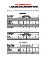
– General Tolerance Values for those drawings that display DWGB105 in the title block but do not display any general tolerance values. The values for tolerance class c, as listed in ISO 2768-1 General Tolerances – Part 1: for linear and angular dimensions without individual tolerance indications, must be applied on those drawings that display DWGB105 in the title block but do not display any general tolerance values. A broken edge is the intersection of two surfaces that are displayed as a chamfer or a radius. For nominal basic sizes below 0.5 mm, a deviation based on design intent must be indicated adjacent to the relevant nominal size(s). Permissible deviation for linear dimensions, except for broken edges, for class c Tolerance class Designation c Description Coarse 0.5 up to 3 mm +/- 0.2 mm Over 3 up to 6 mm +/- 0.3 mm Over 6 up to 30 mm +/- 0.5 mm Over 30 up to 120 mm +/- 0.8 mm Over 120 up to 400 mm +/- 1.2 mm Over 400 up to 1000 mm +/- 2 mm Over 1000 up to 2000 mm +/- 3 mm Over 2000 up to 4000 mm +/- 4 mm Note: For nominal sizes below 0.5 mm, the deviations shall be indicated adjacent to the relevant nominal size(s). Permissible deviations for basic size range
Note: For those basic size ranges above 4000 mm the following tolerance values based on FIAT 01444 degree C (rough) must be applied. Permissible deviations for basic size range Tolerance Value Over 4000 up to 8000 mm +/- 5 mm Over 8000 up to 12000 mm +/- 6 mm Over 12000 up to 16000 mm +/- 7 mm Over 16000 mm +/- 8 mm Permissible deviation for broken edges, for class c Tolerance class Designation c Description Coarse 0.5 up to 3 mm +/- 0.4 mm Over 3 up to 6 mm +/- 1 mm Over 6 mm +/- 2 mm Note: For nominal sizes below 0.5 mm, the deviations shall be indicated adjacent to the relevant nominal size(s). Permissible deviations for basic size range
THE INFORMATION HEREON IS THE CONFIDENTIAL AND PROPRIETARY PROPERTY OF CNH INDUSTRIAL N.V. AND/OR ITS SUBSIDIARIES OR DIVISIONS. ANY USE, EXCEPT THAT FOR WHICH IT MAY BE LOANED, IS PROHIBITED.
UNCONTROLLED COPY When Printed
DWGB105 86979025
Drawing Standards Specifying General Tolerances Permissible deviation of angular dimensions, for class c Permissible deviations for ranges of lengths, in mm, of the shorter side of the angle concerned up to 10 Over 10 up to 50 Over 50 up to 120 Over 120 up to 400 Over 400
Rev F Page 10 of 10
Tolerance class Designation c Description Coarse +/- 1 degree 30 minutes +/- 1 degree 0 minutes +/- 0 degrees 30 minutes +/- 0 degrees 15 minutes +/- 0 degrees 10 minutes
The values for tolerance class L, as listed in ISO 2768-2 General Tolerances – Part 2: Geometrical tolerances for features without individual tolerance indications will be applied on those drawings that display DWGB105 in the title block but do not display any general tolerance values. General tolerance on straightness and flatness, for class L Straightness and flatness tolerances for ranges of nominal lengths up to 10 mm Over 10 up to 30 mm Over 30 up to 100 mm Over 100 up to 300 mm Over 300 up to 1000 mm Over 1000 up to 3000 mm
Tolerance Class L 0.1 mm 0.2 mm 0.4 mm 0.8 mm 1.2 mm 1.6 mm
General tolerance for circularity is equal to the numerical value of the diameter tolerance, but in no case shall it be greater than the respective tolerance value for circular radial run-out. General tolerance on cylindricity is not specified. General tolerance on parallelism is equal to the numerical value of the size tolerance or the flatness/straightness tolerance, whichever is the greater. General tolerance on perpendicularity, for class L Perpendicularity tolerances for ranges of nominal lengths of the shorter side up to 100 mm Over 100 up to 300 mm Over 300 up to 1000 mm Over 1000 up to 3000 mm General tolerance on symmetry, for class L Symmetry tolerances for ranges of nominal lengths up to 100 mm Over 100 up to 300 mm Over 300 up to 1000 mm Over 1000 up to 3000 mm
Tolerance Class L 0.6 mm 1 mm 1.5 mm 2 mm
Tolerance Class L 0.6 mm 1 mm 1.5 mm 2 mm
General tolerance on coaxiality is not specified. General tolerance on circular run-out (radial, axial and any surface of revolution), for class L Tolerance Class Circular run-out tolerances L 0.5 mm THE INFORMATION HEREON IS THE CONFIDENTIAL AND PROPRIETARY PROPERTY OF CNH INDUSTRIAL N.V. AND/OR ITS SUBSIDIARIES OR DIVISIONS. ANY USE, EXCEPT THAT FOR WHICH IT MAY BE LOANED, IS PROHIBITED.
UNCONTROLLED COPY When Printed