Rail Installation Tolerances [PDF]
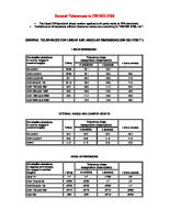
2.6.2 Manufacturers’ tolerances Tolerance Crane runways Diagram S min S Tolerance A of track gauge dimension s of cr
29 0 28KB
Papiere empfehlen


![Rail Installation Tolerances [PDF]](https://vdoc.tips/img/200x200/rail-installation-tolerances.jpg)
- Author / Uploaded
- jebrija
Datei wird geladen, bitte warten...
Zitiervorschau
2.6.2 Manufacturers’ tolerances Tolerance
Crane runways Diagram
S min
S
Tolerance A of track gauge dimension s of crane rails with reference to the rail centre and crane runway length
S max
2
Designation
41409444.eps
Smax = s + A
Tolerance class 3
for s ≤ 16 m: A = ± 3 mm for s > 16 m: A = ± [3 + 0,25 (s – 16)] A in mm us e s in m
for s ≤ 16 m: A = ± 5 mm for s > 16 m: A = ± [5 + 0,25 (s – 16)] A in mm us e s in m
for s ≤ 16 m: A = ± 8 mm for s > 16 m: A = ± [8 + 0,25 (s – 16)] A in mm us e s in m
2000
B = ± 5 mm b = 1 mm
B = ± 10 mm b = 1 mm
B = ± 20 mm b = 2 mm
C = ± 5 mm c = 1 mm
C = ± 10 mm c = 2 mm
C = ± 20 mm c = 4 mm
E = ± 0,5º/% x s in mm us e s in m m Emax = ± 5 mm
E = ±1º/% x s in mm us e s in m m Emax = ± 10 mm
E = ±2º/% x s in mm us e s in m m Emax = ± 20 mm
2000
b
b
-B +B
b
2000
41409544.eps
Position of a rail seen in plan
c
c
2000
2000
c
Tolerance C of the straightness with reference to the height of the crane rail centre and crane rail length Tolerance c of the straightness with reference to 2000 mm measured length (sample measurement) at any point of the crane runway
Tolerance class 2
S min = s – A
-C +C
Tolerance B of the lateral straightness of the rail head with reference to the crane runway length Tolerance b of the lateral straightness with reference to 2000 mm measured length (sample length) at any point of the rail head
Tolerance class 1
2000 41409644.eps
Position of a rail seen in elevation (longitudinal slope)
E
Tolerance E of the height with reference to perpendicular measuring points at every point of the crane runway
+E
s
41409744.eps
Position of rails in relation to one another in elevation (transverse slope) 20320004.tbl
Source: VDI 3576
36
2033522a.p65/0401
Recommended: Tolerance class 2