Caterpillar Digital Voltage Regulator - Service Manual [PDF]
CÑERPItlAR' RENR7941 December2003 )c(0ilffi@A tnons Sp€ SIcnns@toeretnon Sys TcES STrnEand Ad¡ustnnE tr Gaterpillar D
33 0 8MB
Papiere empfehlen


![Caterpillar Digital Voltage Regulator - Service Manual [PDF]](https://vdoc.tips/img/200x200/caterpillar-digital-voltage-regulator-service-manual.jpg)
- Author / Uploaded
- pevare
Datei wird geladen, bitte warten...
Zitiervorschau
CÑERPItlAR'
RENR7941 December2003
)c(0ilffi@A tnons Sp€ SIcnns@toeretnon Sys TcES STrnEand Ad¡ustnnE tr
Gaterpillar Digital Voltage Regulator
(cDvRr
;\
¡01658146
lmportantSafetyInformation Most accidentsthat involveproductoperation,maintenanceand repairare caused by failureto An accidentcan oftenbe avoidedby recognizingpotentially observebasic safetyrulesor precautions. hazardoussituationsbeforean accidentoccurs.A personmust be alertto potentialhazards.This personshouldalso havethe necessarytraining,skillsand toolsto performthesefunctionsproperly. lmproper operation, lubrication, maintenance or repair of this product can be dangerous and could result In injury or death. Do not operate or perform any lubrlcatlon, malntenanceor repalr on thls product, untll you have read and understood the operatlon, lubrlcatlon, malntenanceand repalr informatlon. Safetyprecautionsand warningsare providedin this manualand on the product.lf these hazard warningsare not heeded,bodilyinjuryor deathcould occur to you or to other persons. The hazardsare identifiedby the "SafetyAlert Symbol"and followedby a "SignalWord" such as 'DANGER",'WARNING"or "CAUTION".The SafetyAlert "WARNING" label is shownbelow.
The meaningof this safetyalert symbolis as follows: Attentlon! Become Alert! Your Safety Is Involved. The messagethat appearsunder the warningexplainsthe hazardand can be eitherwrittenor pictoriallypresented. Operationsthat may cause productdamageare identifiedby "NOTICE"labelson the productand in this publication. Caterpillar cannot ant¡cipateevery posslble circumstance that might involve a potential hazard.The warnings In thls publlcation and on the product are, therefore, not all Inclusive. lf a tool, procedure, work method or,operating technique that ls not speclfically recommended by Caterpillar ls used, you must satisff yourself that it is safe for you and for others. You should also ensure that the product wlll not be damaged or be made unsafe by the operation, lubrication, malntenance or ') repalr procedures that you choose. The information,specifications, and illustrations in this publicationare on the basis of informationthat was availableat the time that the publicationwas written.The specifications, torques,pressures, measurements, adjustments,illustrations, and otheritemscan changeat any time.Thesechangescan affectthe servicethat is given to the product.Obtainthe completeand mostcurrentinformationbefore you start any job. Caterpillardealershavethe most currentinformationavailable.
When replacementparts are required for this productCaterpillarrecommendsusing Caterpillar replacementparts or pans wfth equlvalent specificationsincluding,but not limitedto, physlcal dimenslons,type,strengthand materlal. Faitureto heedthis warningcan leadto premature failures,productdamage,personalinjury or death.
¡t ,
¡
- )
3 Tableof Contents
Tableof Contents SpecificationsSection Electrical Dimensions
4 ......................... Z .....................
SystemsOperation$ct¡on Generallnformation ........I StartupProfileFunction 10 .................... Loadingand StoppingProfite VoltageRegulation ........12 LineLossCompensation ...................................... 12 Fleactive VoltageDroop......... ...........13 CrossCurrentCompensation 13 ............................... KVARRegulation ........... 14 ................... PowerFactorRegulation 15 ................... Parameters 16 ................... RemoteCommunication .............. ..... 16
Testingand AdjustingSection Testing and Adjusting Generallnformation ......19 SeMceTools.......... ......19 StartupProcedure ........19 ParameterViewingdrd ConfiguringProcedure.... 20 Tioubleshooting .............. .................. lg No Voltage- Troubleshoot .....................................'{g LowVoltage- Troubleshoot ................................... 45 HighVoltage- Troub|eshoot ..........,,.... .................. 46 Unstable Voltage- Troubleshoot ................ ........... 4T PoorVoltageRegulation- Troubleshoot ................ 48 No LíneLossCompensation .........49 - Tioubleshoot No VoltageDroop- Troubleshoot WiringDiagrams ........... 51
IndexSection Index..........
....;............................ 57
I
^ SpecificationsSection
SpecificationsSection i 01915719
Electrical SMCS Code:4467 Table 1
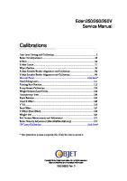
Regulatortemperaturedrift ConfigurableVoltVHzcharacteristic
Lessthan x|lIo Íor any 40 "C (72 "F) changeoverthe ambientoperating lemperaturerange. Twosfope.rang..es adjustablefrom 1 to ,tOyft1'z.See the Regulation Characteristiclllustration.
Regulatorresponset¡me
Maximumof 10 milliseconds.
Begulatorsensing
singrephasesensingis available. lrug ltvts 3-phasesensingis standard. Variable senserange:90 to 600volts.
Regulatorstability
Th.eregulatorrespondsto the fundamentalcomponentof the sensed voltageand remainsstablefor total harmonicdistortionof the generator outputvoltagewaveform,up to 20/".
Telephoneinfluencefac-tor(TlF)
Lessthan 50. complieswith MIL sTD 461c part 9 and vDE 0875 reverN.
Fine voltageadjustrange
t 10%of regulatorsensingvoltage. Regulatorvoltagegaid ltine loss compensat¡on) Adjustablefrom 0 to 10olo. Faultdetectionand identification Diagho-stics identifyoperationoutsideof programmedlimits.Specific fault informationis availableevenatterttré uñ¡thas been poweieooown. CANBUSonly Harmonictolerance The dlgitalvoltage-regulator maintainsprecisecontrolof the generator outputwith up lo 20% harmonicdistortionin the generatoroulputvoltage. Reactivedroopadjustment Adjustablefrom 0 to 10%. Overexcitationprotection
Shutsoff generatoroutputwhen excitationcurrentexceedsnormal operatingcurrentsfor 10 secondsor instantaneous shutoffif outputcurrent exceedsapproximatly28 Amperes.
Ambientoperatingtemperature
-40 "C (-40 "F) to +70'C (+ 1SS"F). -40'C (-40'F) to +85 "C (+ 1BS.F).
Storagetemperaturerange
\
Powerdissipat¡on
5 watts at ¡dle,55 watts at rated output.
Shock
Withstandsup to 20 g's in three mutuallyperpend¡cularplanes.
Vibration
Withstands4.5 g's at frequenciesbeiween1g and 2000 Hz in three mutuallyperpendicularplanes. ,
Salt fog
5% saltsprayfor 48 hoursat 39'C (100.4"F) at11}o/oof the nominal operatingvoltage
Weight
1.47kg (3.24tbl.
Electromagnetic compatibility
Meets89/336/EECElectromagnetic Compat¡bility Directive. 24 r 6 volt DC powersupplyrequired(0.5 amp),
Powersupply
(continued)
5 Specifications Section :
per Standard508, UL FileNo. E97035 UL Recognized No.14-95,CSADileNo.LR 23131 CertifiedperStandardCANICSA-C22.2 Conformsto the followingstandards:RadiatedEmissionsEN50081-2, (10 v/m), Radiated Radiatedlmmunity(electricfield)EN61000-4-3 (10 VRMS),ConductedEmissions EN61000-4-0 lmmunity(conducted) ClassA), ESDlmmunityEN50082-2(4 KV contact, EN50081-2(EN55011, 8 KV air),EFT lmmunityEN50082-2(2 KV couplingclamp),Magnetic lmmunityEN50082-2(30ARMS,50 Hz),SafetyEN61010-1
PoINT(20To 40 Hz) UNDERFREOUENCY GENERATOR OUTPUTVOLTAGE
U
ú7s
DECREASINGSLOPE 2 (0 To 10 V/Hz)
F J
J
z =50 z
.-------!r---l--------
MtNtMUMVOLTAGESETPO|NT(50 - 100 %)
L
5 HZ {FTXED)
be
I
KNEEFREOUENCY
% OF NOM INAL FREQUENC Y
901040043
Summaryof OperatingParameters Specifications
Parameter VoltageRegulation Rating
120 to 15000Volts
GeneratorTYPe
PM SE AREP
Powerlnput
Frequency
Voltage
50 to 400 Hz
80 to 264 Volts(36) 100to 280 Volts(1@)
OumutRating
Sensing Reative DrooP
MaximumContinuous
1150VA or 1900VA Marimumn Forcing (10 Seconds)
Current
Voltage
Gurrent
Voltage
63 0r 125 Volts
12or 10Amperes
125or 250Volts
|
25 or 20 Amperes
Voltage
Maximum VA Burden per g
90 to 600 Volts
1V A
Maximum Current
Maximum VA Burden
5 Amperes Exciter Field Resi€tance
Burden(Gontinuous)
1V A
Minimum Resistance
MaximumResistance
3 Ohms
39 Ohms
7 SpecificationsSection
i01915854
Dimensions SMCS Code:4467
D \LJg \L_Jg @ UFñ
_
ffi cYü:
Z,F1ñ on.l
\\lz jlL +YZ
\\/z lt+_o_é
=lll=
JL Z/\\ l/\ñ
hlñ
JlLz\ñ ,o\ñ ((AA rV
I
"''mffi H TU -.R
lllustrat¡on2 Dimensionsof the DigitalVohageRegulator (A) 276.4mm (10.88¡nch) 4{B) 190.5mm (7.50 inch) (C) 139.7mm (5.50inch)
ú-\
901040044
(D) 162.1mm (6.38¡nch) {El72.9 mm (2.87ínch) (n71,4 mm (2.81inch)
(G)15.0mm(0.59inch) (H)4.06mm(0.16inch)
SystemsOPerationSection i01917398
lnformation General SilCS Code: 4402
s010408 (3) 'Pl 2' Connector (4) "P9'Connector
r DigitalVoltageRegulatoris a based voltageregulator.The main of a digitalvoltageregulatoris to regulate voltageof a genEator that is used ¡tnegeneratorset. Controlpowerfor VoltageRegulatoris suppliedfrom an DCVsource.The power stageof the Regulatorcan be suppliedfrom e. highfrequency, permanentmagnet (PMG), fromthe generatoroutput(shunt ü,or from auxiliarywindingsthat are Qnsomegenerators,Connectionsto the Regulator are madethroughthree type connectors.The communication talVoltageRegulator and a service usinga CANBUSprotocol. Voltage Regulator_ hasthreemultiple-pin, onnectors. Thesebonnectors arelabeled .and"P12",See illustration 3. :l
1
(5) 14" Connector
Connector"P6"is a six-pinheaderthat mateswith a six-pinconnector. Connector"P9"is a nine-pin headerthat mateswith a nine-pinconnector. Connector"P12"is a Wvelve-pin headerthat mates with a twelve-oinconnector.
The regulatorhas a nine-pinD-subconnectorthat is labeled"J4".This connectoris used for interface personalcomputers. with IBM-compatible
Note:The CaterpillarDigitalVoltageRegulator shouldbe hard-wiredto earthgroundwith at leasta 16 AWGcopperwire that is attachedto the ground terminal"P6-6". Note:Whenthe unitis configuredin a systemwith otherdevices,a separatelead shouldbe used to groundthe bus fromeach device.
9
SystemsOperationSection the digital voltage regulatoris remotelyfrom the generator,special be given during installation to ensure proceduresare followedto noisefrom reducingthe electromagnetic of the regulatoror other system
Connector'P9"
mountingthe regulatorremotely,the wires,PMGwires,and exciterfield wires
r be routedin theirownseparatetray Theoptionalcustomer wiríngshould
from all othersignalsin a control luit. The voltagesensingwiresshould together.Exciterfield wiresshouldalso together. lllustration5 Pinoutfor the "pg'Connector
901013761
Table4
P9 Terminal Functions
Terminal
lllustraüon 4 ,Pinoutbr the "p6' Connector
9 0 1013614
Funct¡on
P9-1
GANbus- High
P9-2
CANbus- Low
P9-3
CANbus- Drain(Shietd)
P9-4
ContactSense - Lower
P9-5
ContactSense- Ra¡se
P9-6
ContactSense- Common
P9-7
ContractSense- ExcitationDisable
P9-8
ContactSense - FaultResel
P9-9
ContactSense- Var/pF Enablé
Connector"P12',
Table3
P6 Terminal Funct¡ons Termlnal
Function
P6-1 P6.2
PowerInput