Digital Concrete Rebound Hammer: Instruction Manual [PDF]
I NS TRUCTI O N MA NUA L DIGITAL CONCRETE REBOUND HAMMER MA NUA L CO DE C 3 8 6N Do not attempt to operate this equipm
49 1 704KB
Papiere empfehlen


![Digital Concrete Rebound Hammer: Instruction Manual [PDF]](https://vdoc.tips/img/200x200/digital-concrete-rebound-hammer-instruction-manual.jpg)
- Author / Uploaded
- nizar
Datei wird geladen, bitte warten...
Zitiervorschau
I NS TRUCTI O N MA NUA L
DIGITAL CONCRETE REBOUND HAMMER MA NUA L CO DE
C 3 8 6N Do not attempt to operate this equipment before reading and comprehending the manual in all its parts
USERS: MACHINE MANUFACTURERS | DRAUGHTSMEN |OPERATORS | MAINTENANCE WORKERS | ANY OTHERS
REV.
DESCRIZIONE
06
Manuale Istruzioni
REDATTO/GESTITO APPROVATO Ufficio Tecnico
Resp. Tecnico
COD. IDENT.
PAGINE
DATA EMIS.
C386N.M01.EN.06
18
05/2012
Rev. 06
Descrizione Manuale Istruzioni
Redatto/Gestito Ufficio Tecnico
Approvato Resp.Tecnico
Cod.Ident. C386N.M01.EN.06
GENERAL INDEX Chapter 1 1.01 1.02 1.03 1.04 1.05 1.06 1.07 1.08 1.09 1.10 1.11 1.12 1.13
Chapter 2 2.01 2.02 2.03 2.04
Chapter 3 3.01 3.02
Chapter 4 4.01 4.02
Chapter 5 5.01 5.02 5.03 5.04 5.05 5.06 5.07 5.08 5.09 5.10
Chapter 6 6.01 6.02
GENERAL INFORMATION Warnings WARNING and DANGER indications - SIGNS Aim of the Instructions Manual Modifications and enclosures of the Instructions Manual Constructor Identification Machine Identification Data EC Stamp Usage Functioning system of the instrument
Operators Storage Transportation and Movement Packaging removal
TECHNICAL CHARACTERISTICS General machine description Technical specifications Dimension and weight Electrical supply
GENERAL SAFETY NORMS General norms Machine Safety devices and protection
INSTALLATION INSTRUCTIONS Location Electrical connection
IN FUNCTION - USE Selection and preparation of the test surfaces Switching on the equipment Performing test TEST REPORT CONFIGURATION TEST DESCRIPTION CALIBRATION Switching off Batteries DATA TRANSFER SOFTWARE
MAINTENANCE Ordinary Maintenance Authorised maintenance centres
Chapter 7
SPARE PARTS
Chapter 8
INACTIVITY
Chapter 9
DECOMMISSIONING THE MACHINE
Pagine 2/18
Data Em. 05/2012
Rev. 06
Descrizione Manuale Istruzioni
Redatto/Gestito Ufficio Tecnico
Approvato Resp.Tecnico
Cod.Ident. C386N.M01.EN.06
Pagine 3/18
Data Em. 05/2012
ENCLOSURE DRAWING AND EXPLODED VIEW
Chapter 1
GENERAL INFORMATION
1.01 WARNINGS The manufacturer does not accept any responsibility for direct or indirect damage to people, things or animals and use of the appliance in different conditions from those foreseen. The manufacturer reserves the right to make changes to the documentary information or to the appliance without advance notice. Check the machine responds to the standards in force in the state in which it has been installed. All operations necessary for maintaining machine efficiency before and throughout use are the operator’s responsibility Carefully read the entire manual before operating the machine. It is vital to know the information and limitations contained in this manual for correct machine use by the operator. Interventions are only permitted if the operator is accordingly competent and trained. The operator must be knowledgeable about machine operations and mechanisms. The purchaser must ensure that operators are trained and aware of all the information and clarifications in the supplied documentation. Even with such certainty the operator or user must be informed and therefore aware of potential risks when operating the machine. Safety, reliability and optimum performance is guaranteed when using original parts. Any tampering or modifying of the appliance (electrical, mechanical or other) which has not been previously authorised in writing by the manufacturer is considered abusive and disclaims the constructor from any responsibility for any resulting damage. All necessary operations to maintain the efficiency of the machine before and throughout use are the responsibility of the user
1.02 WARNING AND DANGER INDICATIONS - SIGNS The machine has been designed and constructed according to the current norms and consequently with mechanical and electrical safety devices designed to protect the operator or user from possible physical damage. Residual risks during use or in some intervention procedures on the device are however present. Such risks can be reduced by carefully following manual procedures, using the suggested individual protection devices and respecting the legal and safety norms in force. This manual includes “Warning” and “Danger” indications in relevant chapters. These indications are shown with the words “Danger” or “Warning” in bold font and uppercase to make them highly visible.
“WARNING”
Indicates that machine damage could be caused should indications be ignored.
“DANGER”
Indicates that machine damage and/or injury to the worker could be caused should indications be ignored.
“DANGEROUS ZONE” indicates any zone inside or in the proximity of the appliance in which a person is exposed to the risk of injury or damage to health. 1.03 AIM OF THE INSTRUCTIONS MANUAL This manual has been edited with the aim of providing all machine operators with all the necessary information on installation, use and maintenance from production to scrapping in as comprehensive and clear manner as possible. All the procedures useful for any foreseeable emergency situations have been listed by the manufacturer and can be verified during use. Operators, for whom this manual has been written, due to their competence must give instructions or operate the machine themselves. The instructions manual must be carefully consulted by laboratory or site safety managers, equipment operators and any internal and external maintenance workers. The manual is integral to the product and refers to this appliance only.
Rev. 06
Descrizione Manuale Istruzioni
Redatto/Gestito Ufficio Tecnico
Approvato Resp.Tecnico
Cod.Ident. C386N.M01.EN.06
Pagine 4/18
Data Em. 05/2012
The manual must be safeguarded and always kept near the equipment so that it can be easily consulted whenever necessary. IMPORTANT: The manual does not substitute the experience and technical training of the worker but must be considered a guide for carrying out its functions. Furthermore all the norms and rules the operator should be aware of or consult for correct use of the machine and/or test performance can be found in the manual. This responsibility is entrusted to the installer and Laboratory or Site Manager where the machine is installed. The Constructor is available to provide further information. 1.04 MODIFICATIONS AND ENCLOSURES OF THE INSTRUCTIONS MANUAL This manual reflects the state at the time of the launch of the machine on its market. If any modifications, improvements or adjustments have been made since machine supply the Manufacturer does not have to intervene on the marketed machine and will not consider the machine or the manual deficient or inadequate.
1.05 CONSTRUCTOR IDENTIFICATION MATEST SPA Via Delle Industrie, 25 24048 Treviolo (Bergamo) Italy Tel +39 0352055011 Fax +39 0352055055 Email : [email protected] Internet : www.matest.com 1.06 MACHINE IDENTIFICATION DATA MODEL : C386N PRODUCTION DATA: see EC declaration INSTRUCTIONS MANUAL CODE: C386N.M01.EN.06 1.07 EC STAMP SEE EC DECLARATION
1.08 USAGE Tests on hardened concrete already in use which quality and mechanical characteristics can be divided into destructive and non destructive tests. One of the non destructive tests consists of the ‘mechanical’ method which determines surface hardness. This method involves using the hammer and is based on the existing correspondence between the unit load of compression breakage and surface hardness (obtained by measuring the remaining elastic energy – rebound theory). The hammer tests are used to evaluate, on site and with the due procedure limitations, concrete compression resistance (and uniformity); they therefore allow zones or areas of low (or deteriorated) quality present in already manufactured structures. The Digital Hammer performs tests with continuous and automatic registration of all parameters according to the standards UNI EN 12504-2, ASTM C805, BS 1881:202, NF P18-417, DIN 1048, UNI 9189, UNE 83307. The acquired data can also be transferred to a PC (via a USB interface). It is furnished with data transfer software, USB cable, battery charter, abrasive stone, transportation case. This appliance is for the exclusive use which it has been conceived for. Any other use is considered improper and therefore negligent.
Rev. 06
Descrizione Manuale Istruzioni
Redatto/Gestito Ufficio Tecnico
Approvato Resp.Tecnico
Cod.Ident. C386N.M01.EN.06
Pagine 5/18
Data Em. 05/2012
Machine use is allowed only in places free from danger of explosion or fire. During operation check for conditions of danger. Immediately stop the machine should it be working irregularly, and consult the authorised dealer’s Sales Service department. It is the Client’s responsibility to verify at the time of installation and use that no conditions of use arise which are different to those indicated. Refer to the Constructor when in doubt 1.09 FUNCTIONING SYSTEM OF THE INSTRUMENT The principle for the function of the instrument is that a mass launched from a spring strikes a piston in contact with the surface and the result of the test is expressed in terms of the bouncing distance of the mass. The equipment is constituted by a mobile mass with a certain initial energy, which strikes the surface of a concrete mass. There is a redistribution of the initial kinetic energy following the strike and namely a part is absorbed by the concrete in the form of plastic or permanent deformation energy and another part of the energy is returned to the mobile mass which bounces for a tract in proportion to the remaining energy. An essential condition for the distribution of such energy is that the concrete mass is practically in infinite relationship with the mass of the mobile equipment, otherwise a part of the initial energy, being independent from the relative masses of two bodies that will collide, would be transferred to the concrete in the form of kinetic energy. The condition for infinite mass for the concrete is realized by using very small impact masses. In order to obtain the necessary energy for the impact a spring system is used. The bounce run is determined by the energy of the bounce following the strike with the concrete and by the characteristics of the spring system. All the test devices that are based on the use of the results from the impact energy, must be equipped with a calibration control in that, after prolonged use, the springs modify their elastic constants.
1.10 OPERATORS
DANGER WARNING
The use, transportation, installation, maintenance, demolition and disposal of the appliance are only permitted to “QUALIFIED PERSONNEL”. This manual is exclusively aimed at “QUALIFIED PERSONNEL” and contains the necessary information for machine use.
”QUALIFIED PERSONNEL” means people who, due to their training, experience and education, as well as knowledge of the relevant standards, limitations and measures, have been authorised by the “PLANT SAFETY MANAGER” to carry out any necessary activity and are able to recognise and avoid any possible danger. The manufacturer recommends that the instructions, procedures and recommendations in this manual and the work safety legislation in force be scrupulously adhered to, even with the use of appropriate protection devices (whether individual or part of the machine). Knowledge and respect of the instructions, safety warnings and danger in this manual are all necessary for installation, operation, management and machine maintenance with a minimal risk. The “PLANT SAFETY MANAGER” has the following responsibilities and duties: - To know the machine functions, its commands, safety and protection devices, possible dangers of use and all the information in this manual in detail. This knowledge can only be gleaned from detailed reading of this manual. - To know the safety legislation in force in detail in order to operate the machine - To recognise the “QUALIFIED PERSONNEL” for transportation, handling, installation, use, maintenance, disposal, etc. - Correctly train and educate the “QUALIFIED PERSONNEL” before allowing them access to the machine. The personnel must also be exhaustively trained with regards to the machine’s protection devices.
Rev. 06
Descrizione Manuale Istruzioni
Redatto/Gestito Ufficio Tecnico
Approvato Resp.Tecnico
Cod.Ident. C386N.M01.EN.06
Pagine 6/18
Data Em. 05/2012
- Ensure the machine’s safety devices are not tampered with or removed and are checked on a daily basis. Provide the operator appropriate individual protection devices according to the laws in force. - The constructor is available for clarification, assistance and training and declines all responsibility for damage to things or people resulting from improper, incorrect and negligent use by untrained personnel. 1.11 STORAGE
WARNING
The appliance must be stored and conserved in the original packaging and in a closed environment, protected from atmospheric agents with a minimum temperature of -15C°, and a maximum of +60C° and a maximum humidity of 70%.
1.12 TRANSPORTATION AND MOVEMENT
WARNING
In order to avoid irreparable machine damage, move with care, do not overturn, protect from rain, do not stack, protect the packaging and its contents from bumps and sources of heat.
During transportation and movement it is important to avoid bumps, overloading with other packages, exposure to freezing or heating atmospheric agents, or any other potentially harmful condition to the device, things or people. Machine transportation and movement must be entrusted to Qualified Personnel who can ensure correct movement.
DANGER WARNING
Do not transport or move the product should it be impossible to respect the conditions on the packaging or there be any doubts. Request information from the constructor.
The machine is usually shipped in a semi-rigid box complete of abrasive stone 1.13 PACKAGING REMOVAL After removing the packaging check the machine is complete and that there are no visibly damaged parts. DO NOT USE THE MACHINE and refer to the constructor when in doubt.
DANGER
The components used for packaging (plastic bags, polystyrene, nails, screws, wood, etc) must be kept out of reach of children, as they are sources of danger. These components should be placed in the appropriate containers.
Rev. 06
Descrizione Manuale Istruzioni
Chapter 2
Redatto/Gestito Ufficio Tecnico
Approvato Resp.Tecnico
Cod.Ident. C386N.M01.EN.06
Pagine 7/18
Data Em. 05/2012
TECHNICAL CHARACTERISTICS
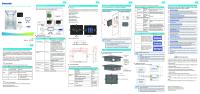
2.01 GENERAL MACHINE DESCRIPTION
A6
A1
CONTROL PERCUSSION STEM
A2 A3
MAIN BODY DISPLAY
A7
A8
DESCRIPTION Mass that give the “hit” to the concrete surface to test, just press to release the mass. Same at the analog version. New display for a rapid visualization of the value.
Rev. 06 A4 A5 A6 A7 A8 A9
Descrizione Manuale Istruzioni
Redatto/Gestito Ufficio Tecnico
FUNCTION BUTTONS BATTERY CONTAINER ABRASIVE STONE USB CABLE BATTERY CHARGER STOP BUTTON
Approvato Resp.Tecnico
Cod.Ident. C386N.M01.EN.06
Pagine 8/18
Data Em. 05/2012
4 buttons allow to scroll between measures and menu. 6 rechargeable battery type AA NiMh 2000mA/h To smooth the surface of concrete to test. Connect the instrument to the pc to download data To recharge the instrument It allows to block the percussion bracket inside the body of the instrument
2.02 TECHNICAL SPECIFICATIONS IMPACT ENERGY (CONCRETE VERSION) IMPACT ENERGY (ROCK VERSION)
2,207 Joule 0,735 Joule
2.03 DIMENSION AND WEIGHT
LENGTH WIDTH HEIGHT WEIGHT
320 mm 65 mm 75 mm 2 kg
2.04 ELECTRICAL SUPPLY POWER UNIT/ BATTERY CHARGER BATTERIES
INPUT 100 ÷ 240 VAC, 50 ÷ 60 Hz, 200 mA OUTPUT 12 VDC, 700 mA (100 VAC), 800 mA (240 VAC) Ni-Mh 9 V, 2400 mA/h
The instrument functions with rechargeable batteries. The power unit supplied with the tool must be inserted to recharge the batteries. The instrument does not have to be switched on for the battery to be recharged. The instrument can be switched on and used when being recharged.
Rev. 06
Descrizione Manuale Istruzioni
Redatto/Gestito Ufficio Tecnico
Approvato Resp.Tecnico
Cod.Ident. C386N.M01.EN.06
Pagine 9/18
Data Em. 05/2012
N.B.: The batteries are usually completely recharged in 8 hours. Recharging stops automatically when the battery has reached its maximum charge.
Chapter 3
GENERAL SAFETY STANDARDS
3.01 GENERAL STANDARDS To ensure the safety of machine operators: · Any tampering with the appliance not pre-emptively authorised by the manufacturer exempts the manufacturer from any responsibility for damage caused by or to it. · The removal or tampering with safety devices entails a violation of the safety standards. · Machine use is only allowed in areas where there is no risk of explosions or fires. · Only the original fittings can be used. The use of unoriginal fittings exonerates the manufacturer from all responsibility. • Check the appliance is in ideal working conditions and that its parts are not worn or faulty before Carry out all necessary maintenance • Be aware of the danger of electrical shocks from direct or indirect contact due to unforeseen electrical faults. • Do not subject the appliance to violent impact. • Do not expose the appliance to fire, welding sparks or extreme temperatures. • Do not bring the appliance into contact with corrosive substances. • Do not wash the appliance with jets of water. · Check the workspace around the machine is clear from potentially dangerous objects. · The machine operator must wear appropriate work clothing such as protective glasses, gloves and mask in order to avoid damage from, for example, harmful dust projection. Wear a lower back support when lifting heavy parts. There should be no hanging objects such as bracelets or otherwise, long hair should be protected with relevant precautions, shoes must be appropriate for the type of operation to be carried out. DURING USE When operating check there are no conditions of danger. Immediately stop the machine when it is functioning irregularly. Contact the authorised Sales Service department. • For the operator’s safety do not touch any part of the appliance when testing and use the appropriate individual protection devices in order to keep the operator safe.
RISK OR DANGER SQUEEZING OF THE HANDS OR OF THE ARMS ABRASION - CUT
PROTECTION DEVICE REINFORCED GLOVES REINFORCED GLOVES
WARNING
MAGNETIC FIELDS Magnetic fields or the presence of strong intensity radiations must be avoided as far as possible. The static electricity or magnetic fields produced by other equipment may interfere with the internal components, resulting in damages to the data stored on the memory card or to the internal circuits of the instrument
WARNING
CONTACT WITH LIQUID CRISTALS In case of fortuitous breakdown of the display, pay particular attention not to injure you with the glass fragments and avoid that the liquid crystal could get in contact with the skin, eyes or mouth. The display is anyhow protected with an anti-shock protective film.
Tampering with the protections or any appliance modification could cause risks to users or other exposed people. The manufacturer does not assume any responsibility for direct or in direct damage to people, things or animals following tampering with the protections. 3.02 MACHINE SAFETY DEVICES AND PROTECTION DEFINITION: Protections are all the safety measures that consist of the use of specific technical means (repairs, safety devices) to protect people from dangers which cannot be limited reasonably in design. The instrument does not have any safety devices as there are no particular risks for the operator during normal use.
Rev. 06
Descrizione Manuale Istruzioni
Chapter 4
Redatto/Gestito Ufficio Tecnico
Approvato Resp.Tecnico
Cod.Ident. C386N.M01.EN.06
Pagine 10/18
Data Em. 05/2012
INSTALLATION INSTRUCTIONS
4.01 LOCATION The equipment must be placed in an ideal position and environment for the use it has been conceived for (laboratory use and protected from atmospheric agents) and that the machine is placed by a qualified operator. ALLOWED TEMPERATURE: from +5°C to +40°C
4.02
ALLOWED RELATIVE HUMIDITY: from 30% to 70%
MAXIMUM HEIGHT OVER SEA LEVEL: 1000 m
ATTENZIONE
TEMPERATURE CHANGES Avoid exposing the instrument to sudden change of temperature; sudden variation of temperature could generate condensation inside the body of the instrument with possible failures of the electrical components. We suggest to wrap the instrument or to put it back in its case in order not to shock it due to thermic change.
ATTENZIONE
DO NOT WET THE INSTRUMENT. The digital concrete Matest test hammer is not waterproof and may become faulty if placed where there is a high degree of humidity or immersed into water. The subsequent formation of rust in the components and internal mechanisms may cause irreparable damages.
ELECTRICAL CONNECTION
DANGER
Wiring of the electrical system must be carried out by qualified personnel Before wiring consult the electric plan linked to the instructions manual and the registration plate on the machine for information regarding supply, frequency and nominal current. Connect the earthing system via the PE terminal (yellow-green) before any other connection. Apply a knife switch at the top of the connecting cable of the machine to the power system. The knife switch must be combined with a safety device against the overload with a differential switch (safety switch). The technical features of the safety device must be in accordance with the standards in force in the country where the machine has been installed.
ELECTRIC TOLERANCES:
Real voltage 10 % of the nominal one Frequency: 1 % of the nominal one in a continuous way 2 % of the nominal one for a short period The harmonic distortion of the sum from the second to the fifth harmonics not more than 10 % of the total voltage as a real value between the conductors. A further distortion of 2% is accepted for the sum from the sixth to the thirtieth harmonics of the real total value between the conductors. With reference to the voltage imbalance of the three-phase voltage, the inverted sequence component and the zero sequence component must not be more than 2% of the direct sequence component of the voltage. The voltage pulses must not last more than 1,5 ms with an up/down time between 500 ms and 500 ms and a peak value not higher than 200 % of the real value of the nominal tension. The electric supply must not be interrupted or zeroed for more than 3 ms at any time. Between two interruptions it must not take more than 1 s. The interruptions must not overcome 20 % of the tension peak for more than one cycle. Between two interruptions it must not take more than 1 s.
Rev. 06
Descrizione Manuale Istruzioni
Redatto/Gestito Ufficio Tecnico
Approvato Resp.Tecnico
Cod.Ident. C386N.M01.EN.06
Pagine 11/18
Data Em. 05/2012
The manufacturer assumes no liability for any damages to people, things and animals caused by the non-compliance of the above instructions
Chapter 5
IN FUNCTION – USE
DANGER WARNING
Before setting the machine in motion it is essential that the Operator and Safety Manager have read the Instructions Manual and understood all parts of the machine and activities linked to it (Risks, Dangers, Functionality, Operation, Protections, Commands, etc.)
5.01 SELECTION AND PREPARATION OF THE TEST SURFACES
The concrete elements to be subjected to the test must be at least 100 mm in thickness and fixed inside a structure. Smaller sample pieces may be subjected to testing as long as these pieces are rigidly supported. Areas that contain the presences of gravel nests, flaking, course textures or others porous elements and in the proximity of significant inertia must be avoided. It should also be avoided, by performing a preliminary rebar locator investigation, the carrying out of sclerometric strikes in areas of passing armatures and in the vicinity of pre-compression cables and wires. In the selection of an area to be subjected to the test the following factors should be considered:
Identification of the areas interested in the passage of armatures; Type of surface; Status of the surface humidity; Carbonatization; Movement of the concrete during the test; Evaluation of the damage level of the surface subject to the test; Test direction; Other appropriate factors as, for example, the type of concrete and the declare resistance class.
The area to be subjected to the test must be approximately 300 mm x 300 mm. Ensure that the distance between the two points of impact are not less that 25 mm and that neither is less that 25mm from the edge. The preparation of the test is carried out using an abrasive medium grain carborundum stone. The smooth or float surfaces may be subjected to testing without rectifications. Remove eventual water residue present on the cement surface. 5.02 SWITCHING ON THE EQUIPMENT Before using the appliance it is highly recommended to check that the appliance and all its accessories work properly and are in good conditions, without defects or damaged parts 1. 2. 3. 4.
5. 6. 7.
8.
Pull concrete test hammer from the case box Select a body with a high mass and a hard, smooth and flat surface Grasp the body of the hammer firmly with both the hands out the Lean the spherical edge of the percussion bracket A1 on the selected surface pushing the body of the instrument and keeping it perpendicular to the surface. Push the appliance until the inner device that holds the percussion bracket will be unhooked. Then gradually remove the instrument from the surface until the percussion bracket will be completely out. The obliquity of the impact plunger A1, towards the longitudinal axis of the instruments has to be considered normal and correct !
To start press the F1 button
The data on the main screen (seen when appliance is switched on) are as follows:
Current date and hour
Rev. 06
Descrizione Manuale Istruzioni
Redatto/Gestito Ufficio Tecnico
Approvato Resp.Tecnico
Cod.Ident. C386N.M01.EN.06
Pagine 12/18
Data Em. 05/2012
Batteries status ( )or the presence of a mains supply ( ). Indication of the progressive number of the current series (“TESTnnnn”). The value of rebound of the last reading (IRb). The middle value of the rebound index (IRbm) referring to the current series of 10 readings. The value of Cubic Compression Strength (CCS), with the possibility to select as a unit (N/mm², psi, kg/cm²), ; the value is available in the range of CCS between 20 and 60, otherwise the advise “Na” (not available) will appear. The angle of rebound (α) referring to the current series of 10 readings (calculated upon first value reading and used to test the coherence of the following readings). The number of readings related to the current series (max 10). The symbology N=nn/mm indicates the display of the “nn” measure out of the “mm” totals (for example N=01/04 indicates the first measure out of 4 totals).
5.03 PERFORMING TEST 1. 2. 3.
Lean the spherical edge of the percussion bracket A1 on the selected surface. pushing the body of the instrument with both the hands and keeping it in a perpendicular position. Apply a gradual pressure to the surface until the percussion is obtained.
ATTENTION
DO NOT TOUCH THE SIDE STOP BUTTON “A9” WHILE YOU’RE PRESSING THE PERCUSSION STEM AND/OR WHEN THE HAMMER MASS IS MOVING, OTHERWISE THE INSTRUMENT WIL BE DAMAGED. THE STOP BUTTON MUST BE PRESSED ONLY TO MOVE THE HAMMER MASS BACK TO ITS HOUSING. ANY OTHER USE IS CONSIDERED INAPPROPRIATE.
4. 5. 6.
Keep the instrument firmly pressed against the surface and wait for the audio signal Now is possible to remove the instrument from the surface The rebound index (lRb) shows the value of the latest test Repeat the test maintaining the same tilt of the instrument (all the measurements must have coherent angling with the first one, otherwise data acquisition will not take place) up to a maximum of 10 readings per sequence with a wait of at least 2 seconds between one reading and the next.
If over 20% of all the measures fluctuates from the average by more than 6 units, the entire set of measurements taken will have to be discarded.
The value measured during the test and the current “job” are transferred to the USB (see chapter “TEST DESCRIPTION”) so that they may be read and used by another instrument connected to it (i.e.: Ultrasonic tester). Check all the tracks left by the instrument on the surface after the impact; if the impact has crashed or perforated the surface, do not consider the test result. Humidity, carbonatization alterations, chemical aggressions, micro cracks, composition and history of the concrete, status of scabrous surface and underlying mass object of the percussions, are all elements that influence the bounce index value. A correctly proportioned concrete presents a highly alkaline (pH13) environment which inhibits the oxidization reactions of the armature. The concrete is however permeable therefore the carbon dioxide may distribute within reacting with the substances that it encounters giving way to the phenomenon of carbonatization (environment pH9) and to dimensional variations that determine the concrete cracks. The cracking sustains the penetration of both carbon dioxide and water vapor which in turn triggers another process: the oxidization of the armature bars/rods, with notable effects. How to save a sequence of measurements 1. Carry out at least one reading of the hammer value. 2.
Press F4 until
3.
Press
appears.
to save the sequence.
How to cancel selection of a sequence of measurements IMPORTANT! If the selected sequence has not been saved to file, the following procedure will cause the acquired data to be lost for the current sequence. 1.
Check that a sequence of measurements has been selected (new or saved to file).
Rev. 06
Descrizione Manuale Istruzioni 2.
Press F4 until
3.
Press
Redatto/Gestito Ufficio Tecnico
Approvato Resp.Tecnico
Cod.Ident. C386N.M01.EN.06
Pagine 13/18
Data Em. 05/2012
appears.
to cancel selection of a sequence of measurements.
How to cancel a reading of a sequence of measurements 1. Carry out at least one hammer value reading. 2.
Press
to scroll through the acquired measurements until the reading of interest is displayed.
3.
Press F4 until
4.
Press
appears.
to cancel the sequence reading.
How to scroll through the readings of a sequence of measurements 1. Check a sequence of measurements has been selected (new or saved). 2.
Press to scroll through the saved measurements for the selected sequence: in the lower part of the screen the current reading will be displayed in real time and the total number of readings (e.g. 03/08).
How to select a sequence of measurements from the file IMPORTANT! If the selected sequence has not been saved to file, the following procedure will result in data loss. 1.
Press
to access the selection menu.
2.
Scroll down the menu by pressing
3.
Press
to access the file screen.
4.
Press
to select the test sequence to be selected (highlighted with “*”).
5.
Press
to confirm (or
and
until
is selected.
to cancel) the selection and return to the main menu.
How to delete a sequence of measurements from the file IMPORTANT! If the selected sequence has not been saved to file, the following procedure will result in data loss. 1.
Press
to access the selection menu.
2.
Scroll down by pressing
3.
Press
to access the file screen.
4.
Press
to select the test sequence to be selected (highlighted with “*”).
5.
Press followed by to delete the selected sequence: the selected measurement will be “marked” as “Cancelled” and will no longer be accessible.
and
until
is selected.
How to delete the file IMPORTANT! If the selected sequence has not been saved to file, the following procedure will result in data loss. 1.
Press
to access the selection menu.
2.
Scroll the menu by pressing
3.
Press
4.
Press followed by main screen.
and
until
to delete the entire file (the operation will take approximately 20 seconds) and return to the
5.04 TEST REPORT The test report should include the following: a) b) c)
is selected.
to access the file screen.
Identification of the element / concrete structure; Position of the test area/s; Test hammer identification;
Rev. 06
Descrizione Manuale Istruzioni
Redatto/Gestito Ufficio Tecnico
Approvato Resp.Tecnico
Cod.Ident. C386N.M01.EN.06
Pagine 14/18
Data Em. 05/2012
d) e) f) g) h) i)
Description of the test area/s preparation; Concrete details and conditions; Date and hour of the test run; Test results (average value) and orientation of the test hammer for each test area; Eventual deviations from the standardized test method; Declaration of the person responsible for the test, whom can attest that the 12504-2:2001 test has been performed excepting that referred to in point (h). Where necessary, the report may also include the single test hammer readings
5.05 CONFIGURATION The instrument can be configured as follows: 1.
Press
2.
Scroll down the menu by pressing
3.
Press
4.
Press
to access the selection menu. and
until
is selected.
to access the configuration screen. to select the parameter to be modified (highlighted with “*”) from: Date and time. Measuring unit to express the CCS value (N/mm², psi, kg/cm²). Sample type undergoing test (“0” concrete cylinder, “1” concrete cube, “2” rock cylinder, “3” rock cube). Correction coefficient of rebound index (multiplier applied to data read by instrument).
5.
Press
and
6.
Press
to stop modification, save the parameters and return to the main screen.
to modify the value of the selected parameter.
5.06 TEST DESCRIPTION Some test descriptives can be defined using the appropriate screen. Proceed as follows: 1.
Press
2.
Scroll down the menu by pressing
3. 4.
Press to access the screen named “job”. Scroll through the descriptive parameters (in order: “JOB” - code “job”, “nPIL” – number of pillars to be tested, “PIL” – pillar the test is referring to, “nFACE” – number of faces of pillars, - “FACE” face number the test is referring to, “ALPHA” – test angulation) which will “accompany” the data from the first sequence which will be filed by pressing
5.
Press
to activate parameter modification.
6.
Press
and
7.
Press
to deactivate parameter modification.
8.
Press
to end modification and return to the main screen.
and
to access the selection menu. and
until
is selected.
. to modify the desired parameter.
5.07 CALIBRATION Proceed as follows for calibration: 1. 2.
Turn the instrument off. Turn the instrument on keeping F2, F3, and F4 pressed down. The calibration screen will appear with the following data: a. Theoretical rebound value for calibration anvil (“Calibration Value”). b. Value of rebound index of last performed reading (IRb).
Rev. 06
Descrizione Manuale Istruzioni c. 3. 4. 5.
Redatto/Gestito Ufficio Tecnico
Approvato Resp.Tecnico
Cod.Ident. C386N.M01.EN.06
Pagine 15/18
Data Em. 05/2012
Median value of rebound index (IRbm) referring to the series of calibration.
Press and to modify the theoretical value of the rebound index for the calibration anvil used for calibration. Perform series of 10 readings on the calibration anvil. At the end of the last reading the main screen will be displayed.
IMPORTANT: The calibration procedure can be cancelled at any time (and return to the main screen) by pressing
.
Calibrating anvil characteristics The verification of the calibration of an anvil does not guarantee that diverse test hammers will produce the same results in other points of the sclerometric scale. In order to verify the calibration of the test hammer, the stainless steel anvil must be placed on a rigid surface. Operate the instruments at least three times prior to initiating the readings from the calibration anvil, to ensure that the mechanics are operating correctly. Then, following this produce, insert the test hammer in the anvil guide ring and carry out a series of strikes (no. = 10).
ATTENTION
The actual standards EN 12504-2 command the checking of the calibration of the test hammer with an anvil for each tests session (EN 12504-2 paragraph 6.1.3). The standard give mandatory indications on how verify and how often, before and after each test sessions. Measures taken on the reference anvil must be saved and compared (EN 12504-2 paragraph 6.3)
For this reason arise from the standard that is unnecessary a certificate of calibration for the test hammer, also if it is provided from the producer or another authority that use a different anvil of calibration, because the value obtained result not comparable with the ones obtained from the user before and after the test on his own anvil of calibration.
5.08 SWITCHING OFF 1. 2. 3. 4.
While in the main window, keep pressed F1 to turn off the instrument. Lean the spherical edge of the percussion bracket A1 on the selected surface. pushing the body of the instrument with both the hands and keeping it in a perpendicular position. Apply a gradual pressure to the surface until the percussion is obtained.
ATTENTION
5. 6. 7.
DO NOT TOUCH THE SIDE STOP BUTTON “A9” WHILE YOU’RE PRESSING THE PERCUSSION STEM AND/OR WHEN THE HAMMER MASS IS MOVING, OTHERWISE THE INSTRUMENT WIL BE DAMAGED. THE STOP BUTTON MUST BE PRESSED ONLY TO MOVE THE HAMMER MASS BACK TO ITS HOUSING. ANY OTHER USE IS CONSIDERED INAPPROPRIATE.
Keep the instrument firmly pressed against the surface and wait for the audio signal Keeping the instrument firmly pressed against the surface, press the A9 stop button. Gradually reduce pressure on the instrument and ensure the rod is kept inside.
5.09 BATTERIES In order to grant a longer long-lasting of the batteries, the instrument switch off automatically the rear-lighting after 30 seconds when the machine is not in use. After 15 minutes, the instrument switch off completely loosing the measurement not previously stored.
Rev. 06
Descrizione Manuale Istruzioni
Redatto/Gestito Ufficio Tecnico
Approvato Resp.Tecnico
Cod.Ident. C386N.M01.EN.06
Pagine 16/18
Data Em. 05/2012
5.10 DATA TRANSFER SOFTWARE
ATTENTION
The download software is normally compatible with the majority of the existing operating systems. Anyway considering: continuous evolution of these systems, several versions available on the market, potential programs configurations on PCs and eventual disturbs generated by some protection softwares like antivirus and firewalls, incompatibility cases cannot be excluded. Should an incompatibility occur or difficulties during installation or use be encountered, please contact Matest technical service.
This procedure will allow you to install the software to transfer data from the instrument C386N to a standard personal computer. Be sure you have the enclosed CD Rom before starting. 1. 2.
Insert the CD Rom into the driver of the computer you want to download.
3. 4.
Follow the screen instructions and confirming the default settings, install the software. Double click on the file :\Driver USB\OneSetup.exe to start installation for the driver for USB connection. Follow the screen instructions and confirming the default settings, install the driver. Connect the USB cable between the instrument and the computer and wait for the periphery to be recognised. Confirm with OK and NEXT on every window which appears until installation has been completed.
5. 6. 7.
With the “autoplay function” ON, the installation procedure starts automatically; otherwise browse the CD and double click on the file .:\setup.exe.
To transfer data from the rebound hammer, switch on the software, selection the correct communications port from the options menu and carry out data transfer of the instrument.
NB: In some O.S. it is mandatory to access with the account of Administrator to install the software.
How to send file data to the PC IMPORTANT! If the selected sequence has not been saved to file, the following procedure could result in data loss. 1.
Press
2.
Scroll down the menu by pressing
3. 4.
Press to start sending data. Install the driver for the serial communication: a.
to access the selection menu. and
until
is selected.
Double click on :\Driver USB\OneSetup.exe file, follow the instructions shown on the video, confirm the default settings, and wait for the end of the setup process. OR
b.
Double click on :\Driver USB\CDM20814_Setup.exe file and wait for the end of the setup process.
ATTENTION
POWER CABLE AND DATA DOWNLOAD Avoid detaching the instrument from the power supply or from the PC with the instrument switched on or during data transfer. Forced interruption of the power could cause data to be deleted or lost or damage to be caused to the internal circuit memory.
Rev. 06
Descrizione Manuale Istruzioni
Chapter 6
Redatto/Gestito Ufficio Tecnico
Approvato Resp.Tecnico
Cod.Ident. C386N.M01.EN.06
Pagine 17/18
Data Em. 05/2012
MAINTENANCE
6.01 ORDINARY MAINTENANCE Carry out a calibration check (“USAGE” CHAPTER) every time new tests are carried out.
DANGER WARNING
Do not perform maintenance – interventions on the machine which have not been quoted and described in this instructions manual without first contacting the manufacturer. Periodically clean all machine parts and oil the unpainted parts in order to preserve the machine and its efficiency. Avoid the use of solvents which damage paint and parts in synthetic material.
6.02 AUTHORISED MAINTENANCE CENTRES For information on the nearest authorised help centre it is essential to contact the manufacturer.
Chapter 7
SPARE PARTS
WARNING DANGER
Chapter 8
Only original spare parts can be used. Use of unoriginal spare parts exempts the manufacturer from all responsibility. Procedures for substitution of spare parts will be provided by the manufacturer along with the part. For spare parts contact the manufacturer’s Sales Service department.
INACTIVITY
Ensure all machine parts are in safe working order before operating it again should the machine be inactive for a long period of time. When in doubt contact the Manufacturer. Chapter 9
DECOMMISSIONING THE MACHINE
Should it be decided that the machine is to be no longer used, proceed as follows: Disconnect the electrical supply network by removing the connecting cable therefore making it unusable. Make the potential sources of danger harmless, such as sharp or protruding parts. Dismantle the machine; divide it into similar parts and dispose of according to the standards in force. Recycling notice for the disposal of electrical and electronical devices This symbol, shown on the device or on the package and/or the documentation, suggests that the device should not be disposed together with other home garbage at the end of its life cycle. To avoid further environment, or health-care damage, caused by the unsuitable disposal of garbage, the user should separate this device from other different types of garbage and recycle it in responsibly to avoid the reuse of material resources. Users must take care at the disposal of the equipment by taking it to the nearest recycling site for appropriate recycling treatment for electrical and electronical devices. Gathering and Recycling deplete devices allow the preservation of natural resources and grant them the adequate treatment by respecting health and environment. For further information on your local recycling site please contact your local council or city waste treatment department. The developer, as producer of electrical and electronical devices, will provide to finance the recycling and treatment services for deplete devices that will come back through these recycling sites, according to the local statement.
Rev. 06
Descrizione Manuale Istruzioni
ENCLOSURE
Redatto/Gestito Ufficio Tecnico
Approvato Resp.Tecnico
DRAWING AND EXPLODED VIEW
Cod.Ident. C386N.M01.EN.06
Pagine 18/18
Data Em. 05/2012