Cat M318 Folleto [PDF]
® M318 Wheel Excavator Cat® 3116 T Engine Operating Weight Bucket Capacities Maximum Reach at Ground Level Digging Dep
36 1 1MB
Papiere empfehlen


![Cat M318 Folleto [PDF]](https://vdoc.tips/img/200x200/cat-m318-folleto.jpg)
- Author / Uploaded
- Santa Rosa Huarocondo
Datei wird geladen, bitte warten...
Zitiervorschau
®
M318 Wheel Excavator
Cat® 3116 T Engine Operating Weight Bucket Capacities Maximum Reach at Ground Level Digging Depth Travel Speed
98 kW/131 hp 17 300 to 18 100 kg 0.40 to 1.05 m3 10 550 mm 7440 mm 34 km/h
The Cat M318 wheel excavator Setting a high standard in mobility, versatility, operator comfort and ease of maintenance.
The 300 Family sleek styling on wheels Both the cab and body have smooth, rounded contours with blended-in roading lights for a modern look. The cab interior combines modern styling with a soft and pleasing color scheme. The M318 offers everything an operator could expect today in a wheel excavator.
A step forward in environmental considerations The Caterpillar 3116 T engine meets regulatory emissions requirements worldwide, including the European Union Non-Road Mobile Machinery Engine Emission Directive 97/68/EC.
The engine has low spectator and operator sound levels and the hydraulic system can be operated with biodegradable oil as an option. These features make the M318 a friendly machine, which helps protect the environment. pg. 8
State-of-the-art hydraulic system The load-sensing hydraulic system with load independent flow distribution offers exceptional operation control, modulation, and multi-function capability. Up to four additional hydraulic functions can be added for maximum application flexibility. pg. 10
Modern electronics A microprocessor together with modern electronics register the operator’s commands and manage the engine and pump interface to help maximize fuel efficiency. pg. 6-7
Ground level maintenance All daily maintenance points are accessible from ground level. A centralized greasing port is located on the right foot of the boom. This allows the operator to grease the front linkage pins from ground level. pg. 10
A choice of the best boom and stick match 2 booms and 5 different sticks allow you to choose the best match for each job. Computer aided design and stress analysis of all front-end structures give the best combination of durability and weight control. pg. 9
The cab: a new reference Pilot operated joysticks control frontend and swing functions. The tiltable steering column and the pedal controls offer optimal comfort. The control panel informs the operator of the machine status at all times. Large windows offer good visibility while roading and working in tight quarters. The fully adjustable seat offers lumbar support. Heater, defroster, and fan keep positive filtered air (warm, fresh, or cool if equipped with the air conditioner option) flowing through the cab at the flip of a switch. pg. 4-5
Cat ‘5 Star Customer Service’ Turns your investment into profit, from purchase to resale through: ■ Equipment Management Services for optimum profit ■ Maintenance Services for equipment protection ■ Predictive Services for optimum availability ■ Reconditioning Services for lower repair cost ■ Your Caterpillar dealer for satisfaction and peace of mind pg. 23
Outstanding operator comfort Plenty of room, all-around visibility, and ergonomic layout for convenient operation. Easy access Conveniently located grab irons and large steps mounted on the undercarriage allow easy access to the cab. A quiet cab The cab is resiliently mounted. Sound suppression panels considerably reduce outside noise levels. A comfortable seat The suspension seat adjusts to the operator’s weight and offers excellent lumbar support. There are height-adjustable armrests and numerous seat adjustments. Outstanding visibility Wide windows help ensure excellent visibility in all directions. This is especially critical when roading the machine or when working on public roadways. A parallelogram windshield wiper clears the front window efficiently in rainy weather. Rear visibility is excellent thanks to the small engine cover. The standard skylight provides upward visibility.
4
Excellent ventilation Strategically located vents circulate forced air, heat, or defrost air for maximum comfort. The two-piece front window has multiple positions. In rainy weather, the lower front window can be tilted inwards to provide fresh air and the skylight can be opened for additional ventilation. For work in hot weather conditions, an optional air conditioner is available. Practical controls ■ The control panel switches are conveniently located. ■ Warning lights are clearly visible on the upper portion of the control panel. ■ Joysticks require low effort and a short stroke for maximum control and efficiency. ■ Ample space is reserved for the additional switches and pedals used to activate optional equipment.
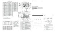
Maestro Mobile electronic system An electronic system matching the state-of-the-art hydraulic system designed specifically for wheel excavator applications.
1 Microprocessor
10 RH console
19 Main pump
2 Power mode III indicator
11 Power mode switch (I/II)
20 Swing pump
3 Hydraulic oil temperature – high
12 Diagnostic tool or laptop-PC running Cat Electronic Technician (ET) software
21 Brake light switch
4 Engine coolant temperature – high 5 Hydraulic oil temperature – low 6 Engine speed dial 7 Travel lock switch 8 Automatic engine control (AEC) switch 9 Back-up switch
13 Travel pedal switch 14 Travel pedal magnet 15 Brake light pressure switch 16 Main pump PRV 17 Swing pump PRV 18 Pilot manifold
6
22 Pressure switch – AEC Main pump 23 Pressure switch – AEC Swing pump 24 Engine speed pick-up 25 Governor actuator and feedback sensor 26 Pressure switch – AEC stick cylinder 27 Pressure switch – AEC boom cylinder
State-of-the-art hydraulic system Closed center, variable flow, load-sensing plus. A variable displacement piston pump powers the boom, stick, bucket, outriggers/dozer, and travel circuit. A gear pump powers the steering system, the brake system, and the pilot control system, and, if equipped, the medium pressure function. A dedicated swing pump A separate dedicated variable displacement piston pump and fixed displacement piston motor power the swing mechanism. This closed hydraulic circuit helps to provide maximum swing performance and control at all times. An efficient and expandable hydraulic system Up to four optional hydraulic valves can be added to the main valve stack for additional hydraulic functions. A medium pressure auxiliary hydraulic circuit is also available. These features offer almost unlimited auxiliary hydraulic capability. Maestro Mobile Control Panel The right side console, shown on page 6, contains switches for the power mode selector, automatic engine control, lights, windshield wiper and washer, and travel speed selector. Integrated electronic system A microprocessor monitors and controls all M318 parameters and functions. The microprocessor was designed specifically for a wheel excavator to maximize the efficiency of the engine and the hydraulic system.
This Electronic Control System monitors and controls the following functions: Engine Speed Control Via Potentiometer – The diesel final control element at the diesel engine is controlled via a potentiometer in the instrument panel. A button on the right joystick immediately sets the idle down manually. Three power mode settings – There are three power mode settings. The operator can choose the best power setting for both engine and hydraulics, without any loss of hydraulic force. Mode III – Works only during travel and is automatically engaged. It provides maximum speed and drawbar pull. Mode II – The standard mode, used for normal truck loading, trenching, and hydraulic hammer use. Mode I – The economy mode, used for lifting, pipe setting, bank forming, grading, slope finishing, and close quarter and precise work. This mode helps ensure minimum fuel consumption. Automatic Engine Speed Control – When activated, this device reduces engine speed to a minimum during periods of inactivity. This reduces noise and saves fuel. Electronic Underspeed Control – Constant electronic monitoring assures that the pump output is always matched to diesel engine power. As a result, a nearly constant diesel engine speed can be maintained. Protective Measures – Maximum power is reduced when engine temperature is too high or the hydraulic temperature is either too low or too high. Diagnostic System – System parameters and failure identification codes can be read by means of a diagnostic tool. Top Speed Adjustment (optional) – This holds the travel pedal in the maximum position to reduce strain on the operator. The pedal is released by activating the brake.
7
Cat 3116 T engine An emission controlled engine offering the latest environmental benefits. ■
■
■
■
Conservative 98 kW rating, high power to displacement ratio of 15.2 kW/liter and low rpm operation help ensure long life and exceptional reliability. The 3116 T engine meets the European Union 97/68/EC Non-Road Mobile Machinery Engine Emission Directive and the current US EPA Non-Road Regulation. Four-stroke-cycle design uses long power strokes for more complete fuel combustion and efficiency. Accurate fuel metering results in low fuel consumption. Long-life design includes large bearing surfaces, alloy steel valves, lightweight cam roller followers, and easily replaceable crankshaft seals.
■
■
■
The engine is designed for high torque rise at medium rpm. This is suited for excavator applications. The engine is longitudinally mounted on the right to make it easier to serve the oil filter, oil filler, oil drain valve, fuel filter, V-belt tightener, and dipstick which are all accessible from ground level. Low engine noise emissions make the M318 a real friendly machine which helps protect the environment: LpA – 72 dB(A); LWA – 101 dB(A) Dynamically measured according to ISO6396 or 95/27/EC.
Undercarriage, outriggers, dozer blade, axles Undercarriage and axles match: providing maximum flexibility and mobility. Undercarriage – A strong and long-life welded frame structure built with large sections and thinner plates for excellent rigidity. The frame has been Finite Element Method analyzed. Both the dozer blade and the outriggers feature a pin-on design. Axles – Heavy duty axles. The front axle offers one of the best axle oscillation and steering in the industry for optimized flexibility and mobility.
8
Outriggers – Recommended for maximum operation stability when digging and lifting. They can be controlled individually to level the machine on slopes. Pin-on design, including standard outriggers cylinder guards. Can be mounted on the front and/or on the rear. Dozer Blade – A useful addition for leveling and backfilling or clean-up work, also used to improve machine stability when digging or lifting. Pin-on design, including standard dozer blade cylinders guard. This can be mounted on the front and/or on the rear.
Booms and sticks Choose the boom/stick combination best matching your needs. Contact your Cat dealer for more information. 1 One-piece Boom 5.3 meters – For all standard applications. It is built with large sections and thinner plates for maximum weight reduction and durability and has been Finite Element Method analyzed. Recommended for hammer applications.
1
2 Hydraulically Adjustable Boom (VA) max. 5.25 meters – For improved visibility and machine roading balance. Indicated when working in tight quarters. It is built with large sections and thinner plates for maximum weight reduction and durability and has been Finite Element Method analyzed. Sticks – 5 stick lengths are available for maximum flexibility. They are built with large sections and thinner plates for maximum weight reduction and durability. They have been Finite Element Method analyzed. ■ Short stick: 1.8 m ■ Medium stick: 2.4 m ■ Long stick: 2.8 m ■ Extra long stick: 4.0 m ■ Material handling stick: 3.2 m.
2
Industrial arrangement – For industrial or agricultural applications choose the best matching boom and the 3.2 m industrial droop nose stick. With this stick, a free swinging work tool can be used. Bucket linkage – Two bucket linkages are offered. One with diverter valve, the other without. 3 Finite Element Analysis – With FEA, a most stable and reliable base frame and upper frame structure could be designed. For maximum strength and best range, also all linkage parts (boom, sticks) have been analyzed to help optimize the balance of weight reduction versus fatigue strength. This also includes the offset boom.
3
9
Hydraulics The M318 hydraulic system provides more performance and efficiency to your jobs. Efficient and expandable hydraulic system – The flow distances between hydraulic components are minimized. This helps provide maximum hydraulic efficiency. The load independent flow distribution together with the separate swing pump helps ensure maximum power at all times. ■ Load independent flow distribution and control system with pressure cutoff. The pump flow is independently and proportionally distributed to the flow users. This is a flow-on-demand hydraulic system offering multifunction capability. ■ Optional hydraulic valves can be flanged to the main valve stack for maximum hydraulic flexibility. Caterpillar XT hoses and couplings – meet the critical flexibility and strength demands of wheel excavator applications. O-ring face seal couplings provide positive sealing for reliable and leakfree connections.
Hammer Lines (optional) – Factory installed hammer hydraulic lines are available. These lines allow single acting function for dedicated proportional hammer foot control for maximum comfort and precision. Optimized hose routing provides excellent protection and durability. High Pressure Hydraulic Lines (optional) – Factory installed high pressure lines are available. They are designed to function with 2-way hydromechanical attachments such as shears and crushers at maximum working pressure and flow. Optimized hose routing provides excellent protection and durability. Medium Pressure Hydraulic Lines (optional) – Factory installed medium pressure lines are available. They are designed to function with double-acting rotating devices such as the ditch cleaning bucket tilt and the clamshell rotation. Optimized hose routing provides excellent protection and durability.
Serviceability Simplified service and maintenance features save you time and money. Fast, easy maintenance means improved uptime and better value. Ground level service points for fuelwater separator, engine oil filter, battery, radiator fluid level, window washer fluid level, fuel filter, engine oil gauge, hydraulic oil level, air cleaner and pilot system filter.
10
Filters and filter locations make maintenance easier. ■ Air cleaner has double layered filter core and built-in air precleaner for better filtration. No tools required to change. ■ Operator is alerted by warning light in cab to need for filter change. ■ Engine oil filter, fuel filter and fuel-water separator are positioned for easier access. ■ Pilot hydraulic system filter keeps contaminates away from the pilot system.
Water separator removes water from fuel even when under pressure and is located in the engine compartment. Remote greasing block on the upper frame with two grease points for the swing bearing and one for the front end attachment to deliver grease to hard to reach locations.
Buckets and work tools A wide variety of buckets and work tools help optimize machine performance. Purpose designed and built to Caterpillar’s high durability standards. Work Tools – A variety of work tools are available from your Cat dealer for the M318 wheel excavator. These include quick couplers, different kinds of grapples, and demolition and sorting tools such as shears, pulverizers, or hydraulic hammers. Tip selection The following tips are available for the buckets for the M318: ■ Long Tips ■ Short Tips ■ Abrasive Tips ■ Penetration Tips ■ Sharp Corner Tips ■ Wide Tips
H120 s
Bucket specifications General Purpose
A Bite width B Tip radius SAE rated capacity Weight with tips Number of teeth
mm mm m3 kg
600 1419 0.40 540 3
750 1419 0.55 560 3
Extreme Service
A Bite width B Tip radius SAE rated capacity Weight with tips Number of teeth
mm mm m3 kg
1100 1240 0.68 472 6
1000 1340 0.70 600 5
1000 1419 0.80 650 4
1100 1340 0.80 640 5
1200 1340 0.90 660 5
1250 1419 1.05 740 5
1800 1082 0.48 364
2000 732 0.54 416
2000 1008 0.40 365
Ditch Cleaning
1800 732 0.48 385 Rigid
Tiltable
Rigid
Tiltable
All buckets include weld-on tooth adapters. All buckets are available with or without adjuster group: All weights are with tips. * J300 tips required, buckets without * require J250 tips. ➤
A
➤
➤
B
➤
Buckets (optional) – A complete range of Cat specifically designed general purpose buckets are available for maximum flexibility. All are available either with or without adjuster groups. A range of tiltable and rigid ditch cleaning buckets are also available. Tips can be chosen from the J250 / J300 G.E.T offering.
11
Engine
Environmental features
Caterpillar four-stroke-cycle, six cylinder 3116 T turbocharged diesel engine.
The M318 offers a list of features to help protect the environment.
Ratings at 2300 rpm Gross power Net power
■
kW
hp
104.5 98
140 131
The following ratings apply at 2300 rpm when tested under the conditions for the specified standard: Net power kW hp ISO 9249 98 131 EEC 80/1269 98 131
■
■
■
Dimensions Bore Stroke Displacement Maximum torque Torque rise
102 mm 130 mm 6.6 liters 608 Nm 21% at 1500 rpm
■
■
An emission controlled engine. Meets the 97/68/EC Non-Road Mobile Machinery Engine Emission Directive and the current US EPA Non-Road Regulation. Longitudinal mounting on the right for easy ground access for service/ maintenance of: oil filter, oil filler, oil drain valve, fuel filter, V-belt tightener, dipstick. An electric 24-volt starting system with a 55 amp alternator and two, 12-volt, 100 amp hour Caterpillar Maintenance-Free batteries. An air cleaner, dry type with radial seal primary and secondary element. Easy and rapid to service and replace. Maximum altitude at full power: 2950 meters.
■
■
■
Low fuel consumption. Compared to power and performance, the M318 has a low level of fuel consumption. Biodegradable hydraulic oil. On the M318, you can use a biodegradable hydraulic oil to help protect the environment and meet governmental requirements in certain countries. The M318 features extremely low operator and spectator sound levels. The emission controlled engine complies with the 97/68/EC NonRoad-Machinery Engine Emission Directive.
Emission values Hydrocarbons (HC) Carbon Monoxide (CO) Nitrogen Oxide (NOx)
g/kWh
below 1.3 below 5.0 below 9.2
Noise levels LpA – 72 dB(A); LWA – 101 dB(A) Dynamically measured according to ISO6396 or 95/27/EC.
Brakes
Axles and final drives
Maintenance free wet-disc service brakes on the front and rear axles are standard.
Planetary axles with planetary gear reduction final drives located in the axle hubs.
■
■
■
■
12
A fully hydraulic service brake system. Braking system is supplied with hydraulic oil from a separate gear pump mounted on the engine. A dual-circuit braking system with independent front and rear axle service brake circuits, for increased safety. Two separate pre-charged hydraulic accumulators, one per circuit, for increased safety. A disc brake parking brake located in the transmission housing. Spring applied and hydraulically released.
M318 specifications
■ ■
■
■
All-wheel drive. High quality graphite iron axle housings for maximum strength and durability. Front steering axle oscillates 9° for improved stability and manoeuvrability in rough terrain. Front axle can be locked from operator station in any position of oscillation for improved working stability.
Ground clearance (with standard tires) Axle static load capacity
375 mm 30 000 kg
Hydraulic system Main Hydraulic System Maximum flow Maximum pressure Implements Travel Optional heavy lift circuit Pilot System Maximum flow Maximum pressure
260 l/min 330 bar 330 bar 370 bar 15 l/min 32 bar
Maestro Mobile electronic control system The microcontroller monitors and controls the interference between the engine and the hydraulics. ■
■
■
■
■
■
Automatically passes into power mode III to help maximize power when travel is activated. Balances pump output and engine power in power modes I and II to help maximize efficiency. Automatic engine control (AEC), provides automatic engine low idle for noise and fuel reduction and operator comfort. 3 power modes: travel mode, standard mode, economy mode. The electrical back-up system for the microprocessor is standard. The switch is in the cab. The central diagnostic function records system parameters or faults. It can be read by dealer technicians with portable diagnostic tools for fast analysis and troubleshooting.
Transmission 2-gear power-shift transmission. Permanent all wheel drive. ■
■
■
■
■
■ ■
Forward, reverse travel and speed are controlled by a single foot pedal on the right side of the steering column. The transmission is protected by a downshift governor to help prevent high-to-low shift until pre-set slower ground speed is reached. The overspeed valve limits downhill travel speed in forward and reverse gears. An optional two-piece drive shaft with an intermediate bearing to help maximize ground clearance is available. The transmission is flanged to the differential housing of the rear axle for maximum protection by axle and base frame, and for better ground clearance. Standard creeper speed. Optional travel speed lock for operator comfort. This locks the travel pedal for long distance travelling.
Steering
Tires
Fully hydraulic, powered by a separate gear pump mounted on the engine.
Dual pneumatic 10.00-20 tires are standard.
■ ■
■
■
Maintenance-free steering system. Synchronized steering cylinder integrated in the steering axle housing to help maximize protection. Steering angle of 35° for reduced turning circle and mobility. Optional battery-powered supplemental steering system.
Outer turning circle diameter 12.7 m Vehicle clearance turning circle with one-piece boom 17.0 m with VA boom 14.5 m
Optional tires: ■ 10.00-20 (dual solid rubber), ■ 18R 19.5 XF (super single).
Speeds 1st gear, forward/reverse 2nd gear, forward 2nd gear, reverse Creeper speed (first gear) Creeper speed (second gear) Drawbar pull Gradeability
9 km/h 20/25/30/34 km/h 20 km/h 3-4 km/h 11-16 km/h 86 kN 57%
Service refill capacities Liters
Fuel Tank Cooling Lubrication Engine Rear axle housing, differential Front steering axle, differential Final drives, front (each) Final drives, rear (each) Powershift transmission Hydraulic system (including tank) Hydraulic tank
M318 specifications
320 35 21 11 8.5 2 2 3 220 135
13
Controls
Swing mechanism
Two pilot-operated revolver type hand levers actuate boom, stick, bucket and swing (SAE pattern).
Dedicated variable displacement axial-piston pump and fixeddisplacement axial-piston motor powers the swing mechanism.
Right lever ■ Move forwards and backwards to lower and raise boom, ■ Move left and right to control bucket curl and dump, ■ Press button on top of control to activate the optional auxiliary circuit in one direction. Left lever ■ Move forwards and backwards to move stick out and in, ■ Move left and right to control the direction of swing, ■ Press button on top of control to activate the optional auxiliary circuit in one direction. ■ Press single button on top of control to activate the swing brake.
Pedals to the right of the steering column ■ Service brake pedal is immediately to the right of the steering column. Fully depressed brake pedal automatically locks oscillating axle ■ Forward and reverse rocker travel pedal is located to the right of the service brake pedal.
■
■
■
Pedals to the left of the steering column ■ Optional VA boom rocker control pedal is immediately to the left of the steering column, ■ Optional hammer or auxiliary hydraulic high pressure function control pedal is located to the left of the VA boom rocker control pedal. Left side console lifts for operator entry and exit. Raising the side console isolates all hydraulic functions except steering. This console must be raised to start the engine.
■ ■
■
■
■
Closed hydraulic circuit, flow and torque controlled with pressure cutoff for maximum swing performance and control. Swing output is power mode influenced. Double-reduction, planetary swing drive. Splash lubricated. Maintenance free gear mechanism. Adjustable constant brake torque while coasting when the swing control is released. Maximum holding torque at operating pressure in a standstill position. Automatic swing brake is activated after 3.5 seconds of no swing operation. Additional emergency swing brake button on joystick. Standard manual swing lock pin actuated from the cab for machine transportation.
Swing system Maximum flow Maximum pressure Swing torque Max. swing speed
112 l/min 315 bar 46.4 kNm 9.4 rpm
Weights Average operating weights include general purpose bucket, 100% fuel and operator. An optional additional counterweight of 400 kg is available.
One-piece boom 1 set of outriggers/dozer
VA boom dozer only
Stick 1800 mm 2400 mm 2800 mm 4000 mm
kg
kg
17 800 17 840 17 900 18 100
17 300 17 350 17 400 17 600
For the following equipment change the above weights: One-piece boom VA boom Dozer only 1 set of outriggers only 2 sets of outriggers 1 set of outriggers/dozer
– +570 –1070 –700 +370 –
-570 – – +370 +440 +1070
Undercarriage with dozer only
2600 4240
14
M318 specifications
Dimensions All dimensions are approximate – measured in mm
B D
A
F
E
C
A Shipping height 1800 mm stick 2400 mm stick 2800 mm stick 4000 mm stick B Shipping length 1800 mm stick 2400 mm stick 2800 mm stick 4000 mm stick C Support Point 1800 mm stick 2400 mm stick 2800 mm stick 4000 mm stick
One-piece boom
VA boom
3200 Cab height Cab height *3210
3220 3210 3230 *3370
9180 8970 **9350 **9370
9080 8900 8900 *8800
4430 3400 **2960 *2720
4500 3540 3150 *2970
D Tail swing radius E Counterweight clearance F Cab height
2450 1280 3100
2500
375 120
2500
3668
* Bucket removed ** Linkage over dozer
Undercarriage with 2 sets of outriggers
Undercarriage with 1 set of outriggers and dozer
Roading position with 2.4 m stick 3180
4000
495
340 1050
1100 2600 5000
800
1100 1050
1100
2600 5030
M318 specifications
15
Working ranges With one-piece boom
Stick Bucket A Maximum cutting height B Maximum loading height C Maximum digging depth D Maximum vertical wall digging depth E Maximum depth of cut, for 2500 mm level bottom F Maximum reach G Maximum reach at ground level Digging forces (SAE): Stick Bucket
16
M318 specifications
1800 mm 0.90 m3 8530 mm 6080 mm 5090 mm 2930 mm 4820 mm 8690 mm 8490 mm
2400 mm 0.80 m3 8890 mm 6330 mm 5690 mm 4360 mm 5470 mm 9230 mm 9040 mm
2800 mm 0.70 m3 8950 mm 6420 mm 6090 mm 4560 mm 5890 mm 9560 mm 9380 mm
4000 mm 0.55 m3 9450 mm 6730 mm 7370 mm 5470 mm 7220 mm 10 720 mm 10 550 mm
108 kN 122 kN
83 kN 114 kN
75 kN 114 kN
57 kN 107 kN
Working ranges With hydraulically adjustable (VA).
Stick Bucket A Maximum cutting height B Maximum loading height C Maximum digging depth D Maximum vertical wall digging depth E Maximum depth of cut, for 2500 mm level bottom F Maximum reach G Maximum reach at ground level Digging forces (SAE): Stick Bucket
1800 mm 0.90 m3 9380 mm 6780 mm 5200 mm 3170 mm 5080 mm 8630 mm 8430 mm
2400 mm 0.80 m3 9840 mm 7180 mm 5790 mm 4430 mm 5690 mm 9190 mm 9000 mm
2800 mm 0.70 m3 10 020 mm 7380 mm 6180 mm 4730 mm 6150 mm 9530 mm 9350 mm
4000 mm 0.55 m3 10 790 mm 7990 mm 7440 mm 5720 mm 7410 mm 10 710 mm 10 550 mm
108 kN 122 kN
83 kN 114 kN
75 kN 114 kN
57 kN 107 kN
M318 specifications
17
Lift capacities** with one-piece boom – 5.30 m 4.5 m
6.0 m
4.4
2.5 2.8 3.5 *4.6 4.3
4.5 m Rear dozer up Rear dozer down Rear stab down 2 sets stab down Dozer and stab down
4.0 4.4 2.4 4.6 *4.9 2.8 5.7 *4.9 3.5 *5.9 *4.9 *4.9 *5.9 *4.9 4.3
3.0 m Rear dozer up Rear dozer down Rear stab down 2 sets stab down Dozer and stab down
*4.6 *4.6 *4.6 *4.6
4.5 m Rear dozer up Rear dozer down Rear stab down 2 sets stab down Dozer and stab down
*5.9
3.0 m Rear dozer up Rear dozer down Rear stab down 2 sets stab down Dozer and stab down
6.8
*5.9 *5.9 *5.9 *5.9 *7.4 *7.4 *7.4 *7.4
3.7 4.2 4.2 *5.5 5.3 *5.5 *7.4 *5.5 6.6 *5.5
2.3 2.7 3.4 5.1 4.1
4.1
2.2 2.5 3.2 4.9 4.0
Ground
1.5 m Rear dozer up Rear dozer down Rear stab down 2 sets stab down Dozer and stab down
•6.1 5.4 *6.1 *6.1
Rear dozer up Rear dozer down Rear stab down 2 sets stab down Dozer and stab down
6.2 *8.9 8.7 *8.9 *8.9
-1.5 m Rear dozer up Rear dozer down Rear stab down 2 sets stab down Dozer and stab down
*7.4
-3.0 m Rear dozer up Rear dozer down Rear stab down 2 sets stab down Dozer and stab down
*9.9
6.1 6.2 *7.4 7.3 *8.5 *7.4 *7.4 *8.5 *7.4 *7.4 *8.5 *7.4 *7.4 *8.5
3.2 4.0 3.8 4.8 7.6 *6.4 6.0 *6.4 3.2 3.9 3.8 4.8 7.6 *6.1 6.0 *6.1
6.0 5.3
4.2 3.8 •4.7 •4.7 2.8 4.2 3.7 •4.9 •4.9
3.0 m
1.5 m Rear dozer up Rear dozer down Rear stab down 2 sets stab down Dozer and stab down
1.5 2.5 1.8 *3.3 2.2 *3.3 3.5 *3.3 2.8 *3.3
1.3 8.23 1.6 2.0 3.1 2.5
1.4 2.3 1.7 *3.4 2.2 3.1 3.4 *3.4 2.8 *3.4
1.2 1.4 1.8 2.9 2.3
8.48
Rear dozer up Rear dozer down Rear stab down 2 sets stab down Dozer and stab down
2.3
1.2 1.4 1.8 2.9 2.3
8.40
-1.5 m Rear dozer up Rear dozer down Rear stab down 2 sets stab down Dozer and stab down
1.3 7.99 1.5 2.0 3.1 2.5
-3.0 m Rear dozer up Rear dozer down Rear stab down 2 sets stab down Dozer and stab down
2.1 2.4 3.1 4.8 3.9
3.5 3.1 *3.6 *3.6
2.1 2.4 3.1 4.8 3.9
2.5 3.8 3.4 *4.0 *4.0
-4.5 m Rear dozer up Rear dozer down Rear stab down 2 sets stab down Dozer and stab down
4.5 m
6.0 m
7.5 m
Undercarriage configuration
m
6.0 m Rear dozer up Rear dozer down Rear stab down 2 sets stab down Dozer and stab down
*4.1
4.5 m Rear dozer up Rear dozer down Rear stab down 2 sets stab down Dozer and stab down
*4.5
*4.1 *4.1 *4.1 *4.1 *4.5 *4.5 *4.5 *4.5
3.0 m Rear dozer up Rear dozer down Rear stab down 2 sets stab down Dozer and stab down
*6.8
1.5 m Rear dozer up Rear dozer down Rear stab down 2 sets stab down Dozer and stab down
6.5
*6.8 *6.8 *6.8 *6.8 *8.3 *8.3 *8.3 *8.3
Rear dozer up Rear dozer down Rear stab down 2 sets stab down Dozer and stab down
6.3 *8.9 8.8 *8.9 *8.9
-1.5 m Rear dozer up Rear dozer down Rear stab down 2 sets stab down Dozer and stab down -3.0 m Rear dozer up Rear dozer down Rear stab down 2 sets stab down Dozer and stab down -4.5 m Rear dozer up Rear dozer down Rear stab down 2 sets stab down Dozer and stab down
6.1 5.3
2.8
6.4 6.4 3.3 *9.9 7.6 *7.2 3.9 *9.9 *9.9 *7.2 5.0 *9.9 *9.9 *7.2 *7.2 *9.9 *9.9 *7.2 6.2
Undercarriage configuration
Ground
Bucket 0.8 m3
Undercarriage configuration
m
6.0 m Rear dozer up Rear dozer down Rear stab down 2 sets stab down Dozer and stab down
Stick 2.4 m
7.5 m
Ground
Bucket 0.9 m3
3.0 m
Undercarriage configuration
6.2 *8.8 8.7 *8.8 *8.8 *11.3 *11.3 *11.3 *11.3 *11.3
2.6 3.0 2.9 *3.6 3.6 *3.6 *4.5 *3.6 4.4 *3.6
3.8 4.3 2.4 2.9 4.4 *5.2 2.8 5.5 *5.2 3.5 *6.8 *5.2 *5.2 *4.4 *6.8 *5.2 4.2 *4.4 3.5 4.1 4.0 *5.9 5.1 5.5 7.9 *5.9 6.3 *5.9
2.2 2.9 2.6 3.3 5.0 *4.7 4.0 *4.7
3.3 4.0 3.8 4.9 7.7 *6.3 6.1 *6.3
2.1 2.8 2.5 3.2 4.9 *4.9 3.9 *4.9
3.2 3.9 3.8 4.8 7.6 *6.3 6.0 *6.3
6.1 5.4
6.0 5.3
6.2 6.3 3.3 4.0 7.4 *7.9 3.8 *5.5 9.8 *7.9 4.9 5.4 *11.3 *7.9 7.7 *5.5 *11.3 *7.9 6.1 *5.5 *5.3 3.5 *5.3 4.1 *5.3 5.2 *5.3 *5.3 *5.3 *5.3
6.0 m Rear dozer up Rear dozer down Rear stab down 2 sets stab down Dozer and stab down
2.6 3.0 3.7 *4.1 *4.1
2.1 2.4 3.1 4.8 3.9 2.1 2.5 3.2 4.9 3.9
4.4 3.9
4.3 3.8
4.2 3.7
1.6 1.9 2.4 3.6 2.9
4.5 m Rear dozer up Rear dozer down Rear stab down 2 sets stab down Dozer and stab down
1.6 *1.9 1.2 8.79 1.8 *1.9 1.4 2.3 *1.9 2.8 3.6 *1.9 *1.9 2.9 *1.9 *1.9
3.0 m Rear dozer up Rear dozer down Rear stab down 2 sets stab down Dozer and stab down
1.5 *2.0 1.1 9.02 1.8 *2.0 1.3 2.3 *2.0 1.7 3.5 *2.0 *2.0 2.8 *2.0 *2.0
1.5 m Rear dozer up Rear dozer down Rear stab down 2 sets stab down Dozer and stab down
1.5 *2.1 1.1 8.95 1.7 *2.1 1.3 2.2 *2.1 1.7 3.4 *2.1 *2.1 2.8 *2.1 2.1
Rear dozer up Rear dozer down Rear stab down 2 sets stab down Dozer and stab down
2.3 *2.4 *2.4 *2.4 *2.4 2.7 *2.8 *2.8 *2.8 *2.8
Ground
Stick 1.8 m
1.2 8.57 1.4 1.8 *2.4 2.2
-1.5 m Rear dozer up Rear dozer down Rear stab down 2 sets stab down Dozer and stab down
1.4 7.82 1.6 2.1 *2.8 2.6
-3.0 m Rear dozer up Rear dozer down Rear stab down 2 sets stab down Dozer and stab down -4.5 m Rear dozer up Rear dozer down Rear stab down 2 sets stab down Dozer and stab down
All weights are in metric tons
3.0 m
4.5 m
6.0 m
Stick 2.8 m
7.5 m m
*4.2
2.6 3.0 *4.2 3.0 *3.8 *4.2 3.7 *3.8 *4.2 *4.2 *3.8 *4.2 *4.2 *3.8 *10.3
7.3 *6.3 3.9 4.4 2.5 3.0 *10.3 8.5 *6.3 4.5 *4.9 2.8 *4.2 *10.3 *10.3 *6.3 5.6 *4.9 3.5 3.9 *10.3 *10.3 *6.3 *6.3 *4.9 *4.9 *4.2 *10.3 *10.3 *6.3 *6.3 *4.9 4.3 *4.2 6.6 *7.9 *7.9 *7.9 *7.9 *4.3
3.5 4.2 4.1 *5.7 5.2 5.6 *7.9 *5.7 6.4 *5.7
*4.3 6.3 *4.3 *4.3 *8.8 *4.3 *4.3 *8.8 *4.3 *4.3 *8.8 *4.3 *4.3 *8.8
3.3 4.0 3.9 4.9 7.7 *6.3 6.1 *6.3
*7.6
3.2 3.9 3.8 4.8 7.6 *6.4 6.0 *6.4
6.0 6.2 *7.6 7.2 *8.9 *7.6 *7.6 8.7 *7.6 *7.6 *8.9 *7.6 *7.6 *8.9 *12.1 *12.1 *12.1 *12.1 *12.1
6.2 6.3 7.4 *8.2 9.7 *8.2 *12.1 *8.2 *12.1 *8.2
6.1 5.4
6.0 5.3
3.2 4.0 3.8 *5.9 4.9 5.3 7.7 *5.9 6.1 *5.9
2.3 2.9 2.6 3.3 5.0 *4.7 4.1 *4.7 2.1 2.8 2.5 3.2 4.9 *4.9 3.9 *4.9 2.1 2.8 2.4 3.1 4.8 *4.8 3.9 *4.8
4.3 3.8
4.2 3.7
4.2 3.7
1.7 1.9 2.4 3.7 3.0
** all lift capacities are with optional 400 kg additional counterweight and optional heavy lift hydraulic circuit.
Bucket 0.7 m3
1.6 *1.7 1.1 9.14 1.9 *1.7 1.3 2.4 *1.7 *1.7 3.6 *1.7 *1.7 2.9 *1.7 *1.7 1.5 *1.7 1.0 9.36 1.8 *1.7 1.2 2.3 *1.7 1.6 3.5 *1.7 *1.7 2.8 *1.7 *1.7 1.5 *1.9 1.0 1.7 *1.9 1.2 2.2 *1.9 1.6 3.4 *1.9 *1.9 2.8 *1.9 *1.9
9.29
1.4 *2.1 1.1 1.7 *2.1 1.3 2.2 *2.1 1.7 3.4 *2.1 *2.1 2.7 *2.1 *2.1
8.92
2.1 2.5 3.1 4.8 3.9
2.5 *2.5 *2.5 *2.5 *2.5
1.3 8.21 1.5 1.9 *2.5 2.4
*9.2
6.5 *6.3 3.4 *9.2 7.7 *6.3 4.0 *9.2 *9.2 *6.3 5.1 *9.2 *9.2 *6.3 *6.3 *9.2 *9.2 *6.3 6.3 3.0 m
4.5 m
6.0 m
7.5 m
9.0 m m
1.8 *2.5 2.1 *2.5 *2.5 *2.5 *2.5 *2.5 *2.5
Stick 4.0 m
*2.5
*3.0 *3.0 *3.0 *3.0 *3.0 *3.9 *3.9 *3.9 *3.9 *3.9
6.9 *6.5 3.7 4.3 2.3 2.9 *10.9 8.2 *6.5 4.3 *4.9 2.7 *4.0 *10.9 10.6 *6.5 5.4 *4.9 3.4 3.0 *10.9 *10.9 *6.5 *6.5 *4.9 *4.9 *4.0 *10.9 *10.9 *6.5 *6.5 *4.9 4.2 *4.0 *5.9 6.4 *5.9 *5.9 *8.0 *5.9 *5.9 *8.0 *5.9 *5.9 *8.0 *5.9 *5.9 *8.0
3.4 4.0 3.9 *5.7 5.0 5.4 7.9 *5.7 6.2 *5.7
2.1 2.8 2.5 3.2 4.9 *4.5 4.0 *4.5
*6.9
5.9 6.2 *6.9 *6.9 *8.7 *6.9 *6.9 8.7 *6.9 *6.9 *8.7 *6.9 *6.9 *8.7
3.2 3.9 3.8 4.8 7.6 *6.2 6.0 *6.2
2.0 2.7 2.4 3.1 4.7 *4.8 3.8 *4.8
*9.5
3.1 3.7 4.7 7.5 5.9 3.1 3.7 4.8 7.6 6.0
5.9 7.1 9.4 *9.5 *9.5 *9.5 *9.5 *11.9 6.1 *11.9 7.2 *11.9 9.6 *11.9 *11.9 *11.9 *11.9
6.1
*9.5 *9.5
*8.7 8.6 *8.7 *8.7 6.2 *7.9 *7.9 *7.9 *7.9
6.0 5.3
3.8 5.9 5.2 *6.2 *6.2 3.9 *5.6 5.3 *5.6 *5.6
1.8 *1.7 1.1 2.0 *1.7 1.3 2.5 *1.7 *1.7 *3.0 *1.7 *1.7 *3.0 *1.7 *1.7
2.6 3.0 1.7 2.1 1.1 *1.0 0.8 10.39 2.9 *3.5 1.9 *2.4 1.3 *1.0 *1.0 3.6 *3.5 2.4 *2.4 1.7 *1.0 *1.0 *3.9 *3.5 *3.5 *2.4 *2.4 *1.0 *1.0 *3.9 *3.5 3.0 *2.4 2.1 *1.0 *1.0
*10.9
*5.9
Bucket 0.55 m3
2.0 2.7 2.3 3.0 4.7 *4.7 3.8 *4.7 2.0 2.4 3.0 4.7 3.8
4.2 3.7
4.1 3.6
4.1 3.6
1.5 2.1 1.8 *2.8 2.3 *2.8 3.5 *2.8 2.9 *2.8
1.0 *1.0 0.8 10.57 1.2 *1.0 0.9 1.6 *1.0 *1.0 2.6 *1.0 *1.0 2.1 *1.0 *1.0
1.4 2.0 1.7 *2.8 2.2 2.7 3.4 *2.8 2.7 *2.8
1.0 *1.1 0.7 10.50 1.2 *1.1 0.9 1.6 *1.1 *1.1 2.5 *1.1 *1.1 2.0 *1.1 *1.1
1.4 1.6 2.1 3.3 2.7 1.3 1.6 2.1 3.3 2.6
*1.3 *1.3 *1.3 *1.3 *1.3 *1.6 *1.6 *1.6 *1.6 *1.6
0.8 10.16 0.9 1.3 *1.3 *1.3 0.9 9.53 1.1 1.4 *1.6 *1.6
Load Point Height
Load Radius Over Rear
Load Radius Over Front
Load Radius Over Side
Load at Maximum Reach * Limited by hydraulic rather than tipping load. The above loads are in compliance with hydraulic excavator lift capacity ratings standard ISO 10567, they do not exceed 87% of hydraulic lifting capacity or 75% of tipping capacity. Weight of all lifting accessories must be deducted from the above lifting capacities.
M318 specifications
19
Lift capacities** with hydraulically adjustable boom – 5.25 m Stick 1.8 m
6.0 m
7.5 m
Undercarriage configuration
m *4.4
4.3 *4.4 2.5 *4.4 *4.4 *4.4 2.9 *4.4 *4.4 *4.4 3.6 *4.4 *4.4 *4.4 *4.4 *4.4 *4.4 *4.4 4.4
6.0 m Rear dozer up Rear dozer down Rear stab down 2 sets stab down Dozer and stab down
4.5 m Rear dozer up Rear dozer down Rear stab down 2 sets stab down Dozer and stab down
*5.4
4.5 m Rear dozer up Rear dozer down Rear stab down 2 sets stab down Dozer and stab down
3.0 m Rear dozer up Rear dozer down Rear stab down 2 sets stab down Dozer and stab down
6.9
4.2 4.4 2.6 *5.4 *4.7 *4.6 2.9 *5.4 *5.4 *4.6 3.6 *5.4 *5.4 *4.6 *4.6 *5.4 *5.4 *4.6 4.3
*6.6
Rear dozer up Rear dozer down Rear stab down 2 sets stab down Dozer and stab down
*12.2
7.3 6.9 *12.2 8.6 *8.8 *12.2 10.8 *8.8 *12.2 *12.2 *8.8 *12.2 *12.2 *8.8
3.9 4.3 4.6 6.7 8.1 *6.3 6.7 *6.3
-1.5 m Rear dozer up Rear dozer down Rear stab down 2 sets stab down Dozer and stab down
*14.2
3.8 4.1 4.4 5.5 8.5 *6.4 6.8 *6.4
-3.0 m Rear dozer up Rear dozer down Rear stab down 2 sets stab down Dozer and stab down
14.7
*6.6 6.8 *4.0 4.4 *6.6 *6.6 *7.9 4.6 *5.9 *6.6 *6.6 *7.9 5.5 5.6 *6.6 *6.6 *7.9 *7.9 *5.9 *6.6 *6.6 *7.9 6.6 *5.9
7.1 7.0 *14.6 8.4 *9.0 *14.6 10.9 *9.0 *14.6 *14.6 *9.0 *14.6 13.6 *9.0 7.1 6.7 *15.2 8.4 *8.8 *15.2 10.9 *8.8 *15.2 *15.2 *8.8 *15.2 13.9 *8.8 3.0 m
Undercarriage configuration
3.0 m Rear dozer up Rear dozer down Rear stab down 2 sets stab down Dozer and stab down
4.3 3.8
2.3 2.7 3.4 5.2 4.2
1.2 1.4 1.9 2.9 2.3
8.42
1.5 m Rear dozer up Rear dozer down Rear stab down 2 sets stab down Dozer and stab down
2.4
1.2 1.4 1.9 2.9 2.3
8.34
Rear dozer up Rear dozer down Rear stab down 2 sets stab down Dozer and stab down
1.3 7.92 1.5 2.0 3.2 2.5
-1.5 m Rear dozer up Rear dozer down Rear stab down 2 sets stab down Dozer and stab down
1.6 7.08 1.9 2.5 *3.6 3.1
-3.0 m Rear dozer up Rear dozer down Rear stab down 2 sets stab down Dozer and stab down -4.5 m Rear dozer up Rear dozer down Rear stab down 2 sets stab down Dozer and stab down
*3.3 3.2 *3.3 *3.3
2.2 2.5 3.2 5.0 4.0
2.6 *3.7 3.5 *3.7 *3.7 *3.6 *3.6 *3.6 *3.6
6.0 m
*4.7 *4.7 *4.7 *4.7 *6.5 *6.5 *6.3 *6.5 *6.5 *6.3 *6.5 *6.5 *6.3 *6.5 *6.5 *6.3 *6.5 *6.5 *6.3 7.4 6.8 *9.1 8.4 *7.9 *9.1 *9.1 *7.9 *9.1 *9.1 *7.9 *9.1 *9.1 *7.9
*11.7 *11.7 *13.9
*14.2 *14.2 14.8
*14.9 *14.9 *12.3
7.5 *11.7 8.5 *11.7 *10.7 *11.7 *11.7 7.2 *14.2 8.4 *14.2 10.9 *14.2 *13.4 7.1 *14.9 8.4 *14.9 10.9 *14.9 13.9
6.9 *12.3 8.2 *12.3 10.6 *12.3 *12.3 *12.3 *12.3
6.8 *8.7 *8.7 *8.7 *8.7 7.1 *8.9 *8.9 *8.9 *8.9 6.8 *9.3 *9.3 *9.3 *9.3
4.3 *4.7 *4.7 *4.7 *4.7 4.2 4.7 *5.7 *6.3 *6.3
*4.2
7.5 m
2.7 3.1 3.7 *4.2 *4.2 *4.2 *4.2 4.4 2.7 *4.9 3.0 *4.9 3.7 *4.9 *4.9 *4.9 4.3 *4.2 *4.2
Undercarriage configuration 3.0
1.6 1.9 2.4 *3.3 *3.3 *3.3 3.0 3.0 1.6 *1.7 1.2 8.75 *4.3 1.9 *1.7 1.4 4.0 2.4 *1.7 *1.7 *4.3 3.6 *1.7 *1.7 *4.3 3.0 *1.7 *1.7
4.0 4.4 4.5 *5.6 5.6 5.6 *7.9 *5.6 6.6 *5.6
2.7 2.9 3.0 3.6 5.1 *4.6 4.3 *4.6
4.1 4.7 5.6 *8.0 *6.7 3.9 4.5 5.6 8.2 6.9 3.6 4.2 5.3 8.2 6.6
2.5 2.9 2.9 3.6 5.2 *4.8 4.4 *4.8 2.3 2.6 3.3 5.1 4.1 2.1 2.5 3.2 4.9 4.0
4.5 *6.2 5.6 *6.2 *6.2 4.2 *6.3 5.7 *6.4 *6.4 4.1 *5.9 5.5 *5.9 *5.9
3.0 m Rear dozer up Rear dozer down Rear stab down 2 sets stab down Dozer and stab down
1.4 2.4 1.7 *3.2 2.2 *3.2 3.4 *3.2 2.8 *3.2
3.1
4.5 m
*4.7
*11.7
Ground
2.5 2.8 2.9 3.6 5.1 *4.8 4.4 *4.8
m
Rear dozer up Rear dozer down Rear stab down 2 sets stab down Dozer and stab down
-4.5 m Rear dozer up Rear dozer down Rear stab down 2 sets stab down Dozer and stab down
*3.1 *3.1
1.3 8.17 1.6 2.0 *3.1 2.5
2.7 *3.8 3.1 *3.8 3.8 *3.8 *3.8 *3.8 *3.8
*9.1
-3.0 m Rear dozer up Rear dozer down Rear stab down 2 sets stab down Dozer and stab down
*3.1 *3.1
*3.8
1.5 m Rear dozer up Rear dozer down Rear stab down 2 sets stab down Dozer and stab down
-1.5 m Rear dozer up Rear dozer down Rear stab down 2 sets stab down Dozer and stab down
6.3 5.5
2.6
3.5 4.1 5.2 8.1 6.5
6.0 m Rear dozer up Rear dozer down Rear stab down 2 sets stab down Dozer and stab down 4.5 m Rear dozer up Rear dozer down Rear stab down 2 sets stab down Dozer and stab down
6.2 5.7
2.6 3.0 3.6 5.2 4.3
Ground
*7.0 *7.0
4.1 4.4 4.6 *5.2 5.6 *5.2 *7.0 *5.2 6.7 *5.2
*3.3 *3.3
4.4 3.9
4.3 3.8
4.5 m Rear dozer up Rear dozer down Rear stab down 2 sets stab down Dozer and stab down 3.0 m Rear dozer up Rear dozer down Rear stab down 2 sets stab down Dozer and stab down
1.6 *1.8 1.1 8.98 1.8 *1.8 1.3 2.3 *1.8 1.7 3.6 *1.8 *1.8 2.9 *1.8 *1.8
1.5 m Rear dozer up Rear dozer down Rear stab down 2 sets stab down Dozer and stab down
1.5 *1.9 1.1 8.90 1.7 *1.9 1.3 2.2 *1.9 1.7 3.5 *1.9 *1.9 2.8 *1.9 *1.9 *2.1 1.1 8.52 *2.1 1.4 *2.1 1.8 *2.1 *2.1 *2.1 *2.1 *2.5 1.4 7.76 *2.5 1.6 *2.5 2.1 *2.5 *2.5 *2.5 *2.5
Rear dozer up Rear dozer down Rear stab down 2 sets stab down Dozer and stab down
Ground
*7.0 *7.0
1.5 m Rear dozer up Rear dozer down Rear stab down 2 sets stab down Dozer and stab down
Stick 2.4 m Bucket 0.8 m3
4.5 m
6.0 m Rear dozer up Rear dozer down Rear stab down 2 sets stab down Dozer and stab down
Ground
Bucket 0.9 m3
3.0 m
Undercarriage configuration
-1.5 m Rear dozer up Rear dozer down Rear stab down 2 sets stab down Dozer and stab down -3.0 m Rear dozer up Rear dozer down Rear stab down 2 sets stab down Dozer and stab down -4.5 m Rear dozer up Rear dozer down Rear stab down 2 sets stab down Dozer and stab down
All weights are in metric tons
3.0 m
4.5 m
6.0 m
7.5 m m
2.8 *3.4 3.1 *3.4 *3.4 *3.4 *3.4 *3.4 *3.4
Stick 2.8 m
** all lift capacities are with optional 400 kg additional counterweight and optional heavy lift hydraulic circuit.
*3.4
Bucket 0.7 m3
*4.2
*4.2 *3.9 2.7 3.1 *4.2 *4.2 *3.9 3.1 *3.7 *4.2 *4.2 *3.9 3.8 *3.7 *4.2 *4.2 *3.9 *3.9 *3.7 *4.2 *4.2 *3.9 *3.9 *3.7
1.7 2.0 2.5 3.7 3.1
*7.9
7.7 *5.8 4.2 4.5 *2.7 3.1 1.7 *1.5 1.1 9.10 *7.9 *7.9 *5.8 4.7 *4.6 3.1 *4.1 2.0 *1.5 1.4 *7.9 *7.9 *5.8 5.7 *4.6 3.7 4.0 2.5 *1.5 *1.5 *7.9 *7.9 *5.8 *5.8 *4.6 *4.6 *4.1 *3.7 *1.5 *1.5 *7.9 *7.9 *5.8 *5.8 *4.6 4.4 *4.1 3.0 *1.5 *1.5 *9.1
4.7 6.8 4.0 4.4 *2.7 3.0 *9.1 8.5 *7.5 *4.6 *5.4 3.0 *4.1 *9.1 *9.1 *7.5 5.6 *5.4 3.6 4.0 *9.1 *9.1 *7.5 *7.5 *5.4 *5.1 *4.1 *9.1 *9.1 *7.5 6.6 *5.4 4.3 *4.1 *11.7
7.4 6.8 *4.1 4.5 *11.7 8.4 *8.5 4.6 *6.1 *11.7 10.7 *8.5 *5.5 5.6 *11.7 *11.7 *8.5 *8.0 *6.1 *11.7 *11.7 *8.5 6.7 *6.1
2.6 2.9 3.0 3.7 5.2 *4.8 4.4 *4.8
*13.8
2.4 2.8 2.8 3.5 5.2 *4.8 4.2 *4.8
7.2 7.0 *13.8 8.5 *8.9 *13.8 11.0 *8.9 *13.8 *13.8 *8.9 *13.8 13.3 *8.9 *14.5
*14.7 *14.7 *14.2
*14.2 *14.2
7.1 *14.7 8.4 *14.7 10.9 *14.7 13.9 7.0 *14.2 8.2 *14.2 10.7 *14.2 13.7
3.9 4.3 4.5 5.6 8.1 *6.3 6.8 *6.3
3.7 4.1 4.3 5.4 *9.1 8.4 *6.3 *9.1 6.7 *6.3 6.6 3.5 *7.6 4.1 *7.6 5.2 *7.6 *7.6 *7.6 6.4
6.2 5.7
6.9
*9.1 *9.1
3.0 m
4.5 m
6.2 5.6
4.4 3.9
4.2 3.8
1.6 *1.5 1.0 9.32 1.9 *1.5 1.2 2.4 *1.5 *1.5 3.6 *1.5 *1.5 3.0 *1.5 *1.5 1.5 *1.6 1.0 9.25 1.8 *1.6 1.2 2.3 *1.6 1.6 3.6 *1.6 *1.6 2.9 *1.6 *1.6 1.4 *1.8 1.1 8.89 1.7 *1.8 1.3 2.2 *1.8 1.7 3.4 *1.8 *1.8 2.8 *1.8 *1.8
2.2 2.6 3.3 5.0 4.0
6.0 m
*2.2 *2.2 *2.2 *2.2 *2.2
7.5 m
1.3 8.17 1.5 1.9 *2.2 *2.2
9.0 m m
*2.8 *2.9 1.8 *1.6 1.1 *2.8 *2.8 *2.9 2.1 *1.6 1.3 *2.8 *2.8 *2.9 *2.6 *1.6 *1.6 *2.8 *2.8 *2.9 *2.9 *1.6 *1.6 *2.8 *2.8 *2.9 *2.9 *1.6 *1.6
Stick 4.0 m
*2.8
Bucket 0.55 m3
*4.1
*4.1 *3.6 2.7 3.1 1.8 2.2 1.1 *0.9 0.8 10.37 *4.1 *4.1 *3.6 3.1 *3.3 2.1 *2.3 1.3 *0.9 *0.9 *4.1 *4.1 *3.6 *3.6 *3.3 2.5 *2.3 1.7 *0.9 *0.9 *4.1 *4.1 *3.6 *3.6 *3.3 *3.3 *2.3 *2.3 *0.9 *0.9 *4.1 *4.1 *3.6 *3.6 *3.3 3.0 *2.3 2.1 *0.9 *0.9 *10.0
*7.5 *6.0 4.0 4.3 2.6 3.1 1.8 2.1 *10.0 8.6 *6.0 4.6 *4.6 2.9 *3.8 2.1 *2.7 *10.0 *10.0 *6.0 5.5 *4.6 3.6 *3.8 2.5 *2.7 *10.0 *10.0 *6.0 *6.0 *4.6 *4.6 *3.8 *3.6 *2.7 *10.0 *10.0 *6.0 *6.0 *4.6 4.2 *3.8 3.0 *2.7
1.1 *0.9 0.7 10.55 1.3 *0.9 *0.9 1.7 *0.9 *0.9 2.6 *0.9 *0.9 2.1 *0.9 *0.9
*10.6
1.0 *1.0 0.7 10.48 1.2 *1.0 0.9 1.6 *1.0 *1.0 2.5 *1.0 *1.0 2.0 *1.0 *1.0
7.2 *6.7 4.0 4.3 *10.6 *8.4 *7.6 4.5 *5.4 *10.6 10.5 *7.6 5.5 *5.4 *10.6 *10.6 *7.6 *7.6 *5.4 *10.6 *10.6 *7.6 6.5 *5.4 *12.1
*7.4 6.7 *12.1 8.5 *8.5 *12.1 10.5 *8.5 *12.1 *12.1 *8.5 *12.1 *12.1 *8.5 13.8
2.5 3.1 2.9 3.5 5.0 *4.3 4.2 *4.3
4.0 4.3 2.5 2.9 4.5 *6.0 2.9 5.5 *5.5 3.6 7.9 *6.0 *5.1 *4.7 6.5 *6.0 4.2 *4.7
7.1 7.0 *14.1 8.3 *8.8 *14.1 10.8 *8.8 *14.1 *14.1 *8.8 *14.1 13.2 *8.8
3.8 4.2 4.4 *6.2 5.5 5.6 8.1 *6.2 6.8 *6.2
2.3 2.8 2.7 3.4 5.1 *4.6 4.1 *4.6
*14.5
3.6 4.0 4.2 *6.1 5.3 5.5 8.2 *6.1 6.5 *6.1
2.1 2.5 3.2 4.9 3.9
7.0 6.7 *14.7 8.3 *9.1 *14.7 10.8 *9.1 *14.7 *14.7 *9.1 *14.7 13.8 *9.1
4.3 3.9
4.3 3.9
4.2 3.7
1.7 *2.0 2.0 *2.7 2.5 *2.7 3.6 *2.7 3.0 *2.7 1.5 1.8 2.3 3.5 2.9
0.8 10.15 *1.1 0.9 *1.1 *1.1 *1.1 *1.1 *1.1 *1.1
1.4 1.7 2.2 3.4 2.7
*1.3
Load Point Height
Load Radius Over Rear
Load Radius Over Front
Load Radius Over Side
*1.1
0.9 9.52 *1.3 1.1 *1.3 *1.3 *1.3 *1.3 *1.3 *1.3
Load at Maximum Reach * Limited by hydraulic rather than tipping load. The above loads are in compliance with hydraulic excavator lift capacity ratings standard ISO 10567, they do not exceed 87% of hydraulic lifting capacity or 75% of tipping capacity. Weight of all lifting accessories must be deducted from the above lifting capacities.
M318 specifications
21
Standard equipment The M318 is a worldwide model from Caterpillar. To provide you with the optimum configuration for your jobs, standard and optional equipment may vary. Please ask your Cat dealer for the latest equipment list for your country. Adjustable pilot operated joystick type lever controls Alternator, 55-amp. Automatic engine speed control (AEC) Batteries, 2 Caterpillar Cab with: Ash tray and lighter Bottle holder Coat hook Cooler box behind operators seat Floor mat Glass, tempered and tinted, EC approved, pressurized and sound suppressed Heater and defroster Hydraulic lock, left side console activated Interior lighting Literature compartment
Roading lights including headlights, taillights and turning lights Suspension seat with: adjustable armrests, lumbar support and retractable seat belt Warning horn Cat 3116 T diesel engine, emission controlled, 98 kW at 2300 rpm 24 Volt electric starting 2950 m altitude capacity Downshift inhibitor Dual tires 10.00-20 Electronic Power Control Unit with backup system Fully hydraulic braking system Full hydraulic steering with emergency steering capability Hydraulic maximum speed limiter Hydrostatic drive 2 speed, 4 wheel drive with on-the-go shifting
Lockable oscillating front axle Power mode selector, economy and standard One-piece drive-shaft Openable two piece front windshield and openable skylight Parking brake Prepared for optional pin-on dozer blade and/or outriggers for front and/or rear installation Positive filtered ventilation, 3 speed Rearview mirror, left and right Steering column, tiltable Swing brake, automatic Variable displacement, load sensing hydraulic system Wide steps on both sides Wiper and washer
Check valves Boom cylinders Stick cylinder VA cylinder Clamshell restraint Dozer blade, front or rear mounted Guards Cab roof (FOPS) Front window Vandalism protection Headrest for driver’s seat Heavy lift arrangement Lights Warning, stick mounted Working for all booms Working, front, cab mounted (2x) Working, rear, cab mounted (1x) Outriggers, pin-on, individually controlled 1 set, front or rear mounted 2 sets, front and rear mounted Overload warning device Rain protective shade for front windscreen Radio Mounting Kit with loudspeakers and antenna (does not include radio)
Radio (includes Radio Mounting Kit) Refuelling pump, electric Rotating beacon Spacer rings, rubber, for use between dual tires Sticks 1800 mm 2400 mm 2800 mm 4000 mm 3200 mm material handling Sound suppression screen Sun blinds For polycarbonate skylight For rear windscreen For right side windscreen Supplemental steering Tilting device (for ditch cleaning buckets only) Tires Tip groups Tool box, left and/or right undercarriage-mounted Travel speed lock Two-piece drive-shaft Wiper and washer for lower front windscreen
Optional equipment Additional counterweight, 400 kg Air conditioner Air horn Air suspension seat Alarm, back-up Anti-drift valve For VA boom cylinder For stick cylinder For bucket cylinder Auxiliary hydraulic circuits (AHC): Medium pressure circuit for booms and sticks High pressure circuit for booms and sticks Hammer circuit for booms and sticks Biodegradable hydraulic oil Booms One piece boom Hydraulically adjustable (VA) Buckets Bucket linkage With diverter valve Without diverter valve Cab, deluxe (openable side window) Cab riser, 1.2 m, fixed
Machines bearing the EC mark, comply with EU Machinery Directive 89/392/EEC pertaining to essential health and safety requirements.
Cat ‘5-Star Customer Service’ Purchase a Cat M318. You know it’s ‘equipped’ with something unique and dependable – Cat ‘5-Star Customer Service’ as delivered by your Cat dealer. Cat ‘5-Star Customer Service’ means peace of mind from the minute you contact your Cat dealer. By building a partnership with your Cat dealer, you can focus on your business instead of your equipment. Cat ‘5-Star Customer Service’ brings together all the products, services and people from Caterpillar and the Cat dealer network and puts them firmly behind you. Count on them to help you maintain your competitive edge. Cat ‘5-Star Customer Service’ includes Equipment Management Services to help you make a better business decision. We’ll assist you in selecting the right Cat equipment to suit your need, to optimize productivity. And we’ll help you make smarter decisions, assist you with machine selection, purchasing or renting options, financing, and projected owning and operating costs. Maintenance Services that enable you to maximize machine availability and performance. Every Cat dealer has a wide choice of maintenance products and services to make sure your equipment achieves maximum performance for the lowest possible cost.
Reconditioning Services for a wider choice of repair alternatives. Caterpillar factory-reconditioned parts and components get your equipment back on the job in the minimum of time and with lower repair costs, contributing to reduced operating costs and a more efficient operation.
Predictive Services to anticipate problems. By anticipating potential problems and preventing unscheduled repairs, Cat Predictive Services make sure that your equipment is always up and ready to run – because maximizing uptime means maximum earning capacity.
Off-the shelf availability of genuine Cat parts. Genuine parts, together with highly experienced, Cat-trained specialists make sure every repair is right first time and your machine is back earning its keep in the shortest possible time.
“Cat 5-Star Customer Service is our commitment to provide you with the best equipment and services for the most cost effective solutions in your business.” Caterpillar and Cat dealers
23
M318 Wheel Excavator
HEHH1140-1 (04/2000) hr
Featured photos of machines may not always include standard equipment. See your Caterpillar Dealer for available options. Materials and specifications are subject to change without notice.
www.CAT.com © 2000 Caterpillar
®