2te15-18 Repair Manual Ce660 [PDF]
2TE15, 18 Pub. No. CE660 Pub. No. CE660 PRINTED IN JAPAN 2TE15, 18 Pub. No. CE660 FOREWORD This Manual contains m
37 0 21MB
Papiere empfehlen


![2te15-18 Repair Manual Ce660 [PDF]](https://vdoc.tips/img/200x200/2te15-18-repair-manual-ce660.jpg)
- Author / Uploaded
- Eriflona
Datei wird geladen, bitte warten...
Zitiervorschau
2TE15, 18
Pub. No. CE660
Pub. No. CE660
PRINTED IN JAPAN
2TE15, 18
Pub. No. CE660
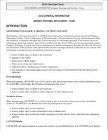
FOREWORD This Manual contains maintenance, specifications and repair procedures for the chassis and body of the TOYOTA ELECTRIC POWERED TOWING TRACTOR 2TE15 and 2TE18. Please use this manual for providing quick and correct servicing of the corresponding towing tractor. This manual deals with the above model as of October 2005. Please understand that disagreement can take place between the descriptions in the manual and actual vehicles due to change in design and specifications. Any change or modifications thereafter will be informed by Toyota Industrial Equipment Parts & Service News. The service standard values described in this manual are measured by using a standard vehicle for examination in the condition specified by TOYOTA Industries Corporation. In an actual operation, therefore, they may be changeable according to the meteorological, road, servicing, or operating condition.
SECTION INDEX NAME
SECTION
GENERAL BATTERY CHARGER CONTROLLER MULTI-DISPLAY FUNCTION ELECTRICAL SYSTEM TROUBLESHOOTING MOTOR DRIVE UNIT REAR AXLE FRONT AXLE SUSPENSION STEERING BRAKE BODY APPENDIX
0 1 2 3 4 5 6 7 8 9 10 11 12 13 14
0-1
GENERAL Page
Page
EXTERIOR VIEW ................... 0-2
BOLT & NUT TIGHTENING TORQUE ............................ 0-19
VEHICLE MODELS................ 0-8 FRAME NUMBER .................. 0-8 HOW TO USE THIS MANUAL .............................. 0-9 EXPLANATION METHOD .......... 0-9
STANDARD BOLT & NUT TIGHTENING TORQUE.......... 0-19 BOLT STRENGTH CLASS IDENTIFICATION METHOD AND TIGHTENING TORQUE.......... 0-19
TERMINOLOGY ........................ 0-10
HEXAGON FLANGE BOLT TIGHTENING TORQUE.......... 0-21
ABBREVIATIONS ..................... 0-10
PRECOATED BOLTS............... 0-21
SI UNITS.................................... 0-11
OPERATING TIPS ............... 0-12 GENERAL INSTRUCTIONS ..... 0-12 JACKING UP............................. 0-13 HOISTING THE VEHICLE......... 0-14 WIRE ROPE SUSPENSION ANGLE LIST ........................... 0-15 SAFE LOAD FOR EACH WIRE ROPE SUSPENSION ANGLE 0-15 COMPONENTS WEIGHTS ....... 0-16 CAUTION FOR TOWING .......... 0-16 ELECTRICAL PARTS INSPECTION........................... 0-17
HIGH PRESSURE HOSE FITTING TIGHTENING TORQUE ............................ 0-22 RECOMMENDED LUBRICANT QUANTITY AND TYPES .... 0-22 LUBRICATION CHART ....... 0-23 PERIODIC REPLACEMENT OF PARTS AND LUBRICANTS .................... 0-24 PERIODIC MAINTENANCE ................. 0-25 INSPECTION METHOD............ 0-25
0 0 0 0 0 0 0 0 0 0 0 0 0 0 0 0 0 0 0
0-2
EXTERIOR VIEW 2TE15
0-3 2TE18
0 0 0 0 0 0 0 0 0 0 0 0 0 0 0 0 0 0 0
0-4 2TE15 (W/ wind top)
0-5 2TE18 (W/ wind top)
0 0 0 0 0 0 0 0 0 0 0 0 0 0 0 0 0 0 0
0-6 2TE15 (W/ steel cabin)
0-7 2TE18 (W/ steel cabin)
0-8
VEHICLE MODELS Model
2TE15, 2TE18
Control method
Microcomputer Voltage
(V)
80
Battery Quantity
(AH/5HR)
445 (STD) / 470 (OPT)
FRAME NUMBER Vehicle model
2TE15
2TE18
Punching format
2TE15-10011
2TE18-10011
Punching position
Frame No. punching position
0-9
HOW TO USE THIS MANUAL EXPLANATION METHOD 1.
Operating procedure (1) Operating procedures are described using either pattern A or pattern B. Pattern A : Each step of the operation is explained with its own illustration. Pattern B : Each step of the operation is explained with reference to step numbers in a single illustration. Explanations in the form of point operations, cautions, and notes follow.
Example of pattern B
DISASSEMBLY • INSPECTION • REASSEMBLY Tightening torque unit→T=N·m (kgf-cm) [ft-lbf]
• Some step numbers may be omitted in some illustrations.
4 2
1
3
7 5
6 T=46.1 to 48.1 (470 to 490) [34.0 to 35.5]
8
5 9
1
Disassembly Procedure 1.
Remove the cover. [Point 1]
2.
Remove the bushing. [Point 2] Ã Operation to be explained in following pages. Remove the gear.
3.
Point Operations Explanation of operation point with illustration. É
[Point 1]
Disassembly: Make match marks before removing the pump cover. [Point 2] Inspection: Measure the bushing inside diameter. Limit: 19.12 mm
0-10 2.
How to read component figures (1) The component figures use the illustration in the parts catalog for the vehicle model. Please refer to the catalog to check the part name.
3.
(Example)
3201 Parts catalog FIG number
Matters omitted from this manual (1) This manual omits descriptions of the following jobs, but perform them in actual operation: (a) Cleaning and washing of removed parts as required (b) Visual inspection (partially described)
TERMINOLOGY Caution: Important matters, negligence of which may cause accidents. Be sure to observe them. Note: Important items, negligence of which may cause accidents, or matters in operating procedure which require special attention. Standard: Value showing the allowable range in inspection or adjustment. Limit: The maximum or minimum value allowed in inspection or adjustment.
ABBREVIATIONS Abbreviation
Meaning
Abbreviation
Meaning
ASSY
Assembly
SAE
Society Automotive Engineers (USA)
ATT
Attachment
SST
Special Service Tool
LH
Left Hand
STD
Standard
L/
Less
T=
Tightening Torque
OPT
Option
{{T
Number of teeth ({{T)
O/S
Oversize
U/S
Undersize
PS
Power Steering
W/
With (what follows is included)
RH
Right Hand
0-11
SI UNITS Meaning of SI This manual uses SI units. SI represents the International System of Units, which was established to unify the various systems of units used in the past for smoother international technical communication.
New Units Adopted in SI Conversion rate *1 (1 [conventional unit] = X [SI unit])
Item
New unit
Conventional unit
Force *2
N (newton)
kgf
Torque *2 (Moment)
N·m
kgf·cm
1 kgf·cm = 9.80665 N·m
Pressure
Pa (pascal)
kgf/cm2
1 kgf/cm2 = 98.0665 kPa = 0.0980665 MPa
↑
↑
mmHg
1 mmHg = 0.133322 kPa
Revolving speed
r/min
rpm
Spring constant *2
N/mm
kgf/mm
1 kgf = 9.80665 N
1 rpm = 1 r/min 1 kgf/mm = 9.80665 N/mm
Reference: *1 : X is the value obtained by converting 1 [in conventional unit] into the SI unit. It is also used as the conversion rate between conventional and SI units. *2 : In the past, kilogram (kg), representing mass, was often used in place of weight kilogram (kgf), which should be used as the unit of force.
Conversion between Conventional and SI Units Equation for conversion Value in SI unit = Conversion rate × Value in conventional unit Value in conventional unit = Value in SI unit ÷ Conversion rate
Conversion rate: Figure corresponding to X in the conversion rate column in the table above
0-12
OPERATING TIPS GENERAL INSTRUCTIONS 1.
Safe operation (1) After jacking up, always support with wooden blocks or rigid stands. (2) When hoisting the vehicle or its heavy component, use wire rope(s) with a sufficient reserve in load capacity. (3) Be sure to disconnect the battery plug before servicing of electrical parts.
2.
Skillful operation (1) Prepare the tools, necessary measuring instruments (circuit tester, megohmmeter, oil pressure gauge, etc.) and SSTs before starting operation. (2) Check the cable color and wiring state before disconnecting any wiring. (3) When overhauling functional parts, complicated sections or related mechanisms, arrange the parts neatly to prevent confusion. (4) When disassembling and inspecting a precision part such as the control valve, use clean tools and operate in a clean location. (5) Follow the specified procedures for disassembly, inspection and reassembly. (6) Always replace gaskets, packing, O-rings, self-locking nuts and cotterpins with new ones each time they are removed. (7) Use genuine Toyota parts for replacement. (8) Use specified bolts and nuts and observe the specified tightening torque when reassembling. (Tighten to the medium value of the specified tightening torque range.) If no tightening torque is specified, use the value given in the STANDARD BOLT TIGHTENING TORQUE table.
3.
Protection of functional parts (1) Before connecting the battery plug after vehicle inspection or maintenance, thoroughly check each connector for any connection failure or imperfect connection. Failure or imperfect connection of connectors related to controllers, especially, may damage elements inside the controllers.
4.
Defect status check Do not start disassembly and/or replacement of components immediately, but first check that disassembly and/ or replacement of them is necessary for the defect.
5.
Waste fluid disposal Always use a proper container when draining waste fluid from the vehicle. Careless discharge of oil, fuel, coolant, oil filter, battery or other harmful substance may adversely affect human health and the environment. Always collect and sort well, and ask specialized companies for appropriate disposal.
0-13
JACKING UP Always observe the following instructions when jacking up the vehicle: • Park the vehicle on a flat surface. Be sure to avoid an inclined or rough surface. • Use a jack with ample capacity and jack up the vehicle at the specified jack-up point. Jacking up at any other point is dangerous. • Always support the load of jacked-up vehicle with wooden blocks at specified points. Supporting the vehicle with the jack only is very dangerous. • Never, under any circumstances, put any part of the body (including hands and feet) under the jackedup vehicle.
Jack-up point Wooden stand point
0-14
HOISTING THE VEHICLE When hoisting the vehicle, always observe the specified hoist attachment section and method. Never hoist by any other attachment section as it is very dangerous. Caution: Be sure to attach the belt with a thick cloth under the belt.
Note: For vehicles with rear under mirror, remove it before attaching belt.
Caution: Hold tightly so as not to allow the belt to dislocate. For that, use shackles.
0-15
WIRE ROPE SUSPENSION ANGLE LIST Tension
Compression
0°
1.00 time
0 time
Suspension method
Suspension angle
Tension
Compression
90°
1.41 time
1.00 time
Suspension method
90°
1. 41
tf
1 tf
Suspension angle
2t
2t
30° 0.27 time
120°
tf
1.04 time
1.04
30°
2.00 time
1.73 time
120° 2
tf
2t
1.16 time
60°
0.58 time 1.1 6t f
60°
2t
2t
SAFE LOAD FOR EACH WIRE ROPE SUSPENSION ANGLE Unit: N (ton:tf) Rope diameter mm
Cutting load
6
Single-rope suspension
Two-rope suspension
Four-rope suspension
0°
0°
30°
60°
90°
0°
30°
60°
90°
21380 (2.18)
3040 (0.31)
6080 (0.62)
5880 (0.60)
5200 (0.53)
4310 (0.44)
12160 (1.24)
11770 (1.20)
10400 (1.06)
8630 (0.88)
8
31480 (3.21)
4410 (0.45)
8830 (0.90)
8530 (0.87)
7650 (0.78)
6280 (0.64)
17650 (1.80)
17060 (1.74)
15300 (1.56)
12550 (1.28)
10
49230 (5.02)
6960 (0.71)
14020 (1.43)
13440 (1.38)
11770 (1.20)
9810 (1.00)
27460 (2.80)
26480 (2.70)
23540 (2.40)
19610 (2.00)
12.5
76880 (7.84)
10980 (1.12)
21570 (2.20)
21280 (2.10)
18630 (1.90)
14710 (1.50)
43150 (4.40)
41190 (4.20)
37270 (3.80)
29420 (3.00)
14
96400 (9.83)
13730 (1.40)
27460 (2.80)
26480 (2.70)
23540 (2.40)
18630 (1.90)
54920 (5.60)
52960 (5.40)
47070 (4.80)
37270 (3.80)
0-16
COMPONENTS WEIGHTS Unit: kg (lb) Item
Weight
Battery ASSY
1150 (2535) 2TE15
102 (225)
2TE18
96 (212)
2TE15
400 (882)
2TE18
430 (948)
Drive motor ASSY
Rear axle and drive unit W/ drive motor
Front axle ASSY (W/ spring)
150 (331) 2TE15
3150 (6945)
2TE18
3510 (7738)
Vehicle weight (W/ battery)
CAUTION FOR TOWING 1.
When towing the vehicle always lift the front wheels away from the ground.
2.
The traveling speed in towing must not exceed the maximum traveling speed of the vehicle.
3.
Always set the key switch to OFF and the direction switch to the neutral position before starting towing.
In case of towing by connection with a wire rope with the operator on the vehicle, however, set the key switch to ON and always set the direction switch to the towing direction for PS operation.
0-17
ELECTRICAL PARTS INSPECTION 1.
Always disconnect the battery plug before inspecting or servicing electrical parts.
2.
Pay sufficient attention when handling electronic parts. (1) Never subject to electronic parts, such as computers and relays, to impact. (2) Never expose electronic parts to high temperature or moisture. (3) Do not touch connector terminals, as they may be deformed or damaged due to static electricity.
3.
Use a circuit tester that matches the object and purpose of measurement. Analog type : This type is convenient for observing movement during operation and the operating condition. The measured value should be used only for reference or rough judgement. Digital type : A fairly accurate reading is possible. However, it is difficult to observe operation or movement. (1) Difference between results of measurement with analog and digital types * The results of measurements using the analog type and the digital type may be different. Use the circuit tester according to its instruction manual. Differences between the polarities of the analog type and the digital type are described below. (a) Analog circuit tester Forward
Example of measurement result Tester range: kΩ range
Reverse
Forward direction: Continuity 11 kΩ Reverse direction: No continuity ∞ Black tester probe
Red tester probe
Red tester probe
Black tester probe
(b) Digital circuit tester Forward
Example of measurement result Tester range: MΩ range
Reverse
Forward direction: Continuity 2 MΩ Reverse direction: No continuity ∞ Red tester probe
Black tester probe
Black tester probe
Red tester probe
0-18 4.
Difference in result of measurement with circuit tester: The circuit tester power supply voltage depends on the tester type. 1.5 V, 3.0 V or 6.0 V is used. The resistance of a semiconductor such as a diode varies with the circuit tester power supply voltage. The diode characteristics are shown in the figure below. The resistance values of the same semiconductor measured with two types of circuit testers having different power supply voltages are different. This manual describes the results of measurement with a circuit tester whose power supply voltage is 3.0 V. (mA)
6
Forward current
5 4 3
Silicon diode
2 1 0
0.1 0.2 0.3 0.4 0.5 0.6 0.7 0.8 (V) Forward voltage
Difference in measurement result by measurement range (analog type): In the analog type circuit tester, changing the measurement range switches over the internal circuit to vary the circuit resistance. Even when the same diode is measured, the measurement result varies with the measurement range. Always use the range described in the repair manual for measurement.
Resistor
Meter
0Ω Variable resistor
Current flow
5.
Germanium diode
Resistor Range: × 10
(SW1)
Resistor Range: × 1
(SW2)
Power source: 1.5 V
Red
Black
0-19
BOLT & NUT TIGHTENING TORQUE STANDARD BOLT & NUT TIGHTENING TORQUE Tightening torques of standard bolts and nuts are not indicated throughout the manual. Use the charts and table below to judge the standard tightening torque. 1.
Judge the tightening torque for the hexagon head bolt, welded bolt or stud bolt having the standard bearing surface according to the tightening torque table by identifying the bolt strength class from the table below.
2.
Judge the tightening torque for the hexagon flange bolt based on the threading diameter.
3.
The nut tightening torque can be judged from its corresponding bolt type.
BOLT STRENGTH CLASS IDENTIFICATION METHOD AND TIGHTENING TORQUE Identification by Actual Part Type
Shape and class
Number in relief or hallmark on the head
Hexagon head bolt (standard)
Class 4 = 4T 5 = 5T 6 = 6T 7 = 7T 8 = 8T
No mark
4T
Bolt with two raised lines on head
5T
Bolt with three raised lines on head
7T
Bolt with four raised lines on head
8T
Welded bolt
4T
No mark
4T
2 mm groove(s) on one/both edge(s)
6T
Stud bolt
0-20
Identification by Part No. Type
Part No.
Shape
91611-40625 Nominal diameter
Nominal length Hexagon bolt
Nominal diameter Class Nominal length
92132-40614 Nominal diameter
Nominal length (mm) Stud bolt
Nominal diameter Class
Nominal length
Tightening Torque Table Standard tightening torque
Class
Nominal diameter mm
Pitch mm
N·m
kgf·cm
ft·lbf
4T
6 8 10 12 14 16
1.0 1.25 1.25 1.25 1.5 1.5
5.4 13 25 47 75 113
55 130 260 480 760 1150
48 in·lbf 9 19 35 55 83
5T
6 8 10 12 14 16
1.0 1.25 1.25 1.25 1.5 1.5
6.5 16 32 59 91 137
65 160 330 600 930 1400
56 in·lbf 12 24 43 67 101
6T
6 8 10 12 14 16
1.0 1.25 1.25 1.25 1.5 1.5
7.8 19 39 72 108 172
80 195 400 730 1100 1750
69 in·lbf 14 29 53 80 127
7T
6 8 10 12 14 16
1.0 1.25 1.25 1.25 1.5 1.5
11 25 52 95 147 226
110 260 530 970 1500 2300
8 19 38 70 108 166
8T
6 8 10 12 14 16
1.0 1.25 1.25 1.25 1.5 1.5
12 29 61 108 172 265
125 300 620 1100 1750 2700
9 22 45 80 127 195
0-21
HEXAGON FLANGE BOLT TIGHTENING TORQUE Nominal diameter mm
Pitch mm
5
0.8
6
1.0
8
1.25
10
1.25
12
1.25
14
1.5
16
1.5
Standard tightening torque N·m (kgf·cm) [ft·lbf]
Remarks
7.5 (76.5) [5.5] Built-in washer 12.5 (128) [9.2] 13 (133) [9.6]
Built-in washer
31 (316) [22.9] 30 (306) [22.1]
Built-in washer
64 (653) [47.2] 63 (643) [46.5]
Built-in washer
115 (1173) [84.9] 115 (1173) [84.9]
Built-in washer
180 (1837) [133] 180 (1837) [133]
Built-in washer
280 (2857) [207] 275 (2806) [203]
Built-in washer
PRECOATED BOLTS 1.
Do not reuse a precoated bolt without using appropriate procedures as it is in the following cases: (1) After it has been removed. (2) When it has been moved by tightness check, etc. (loosened or tightened) Note: For torque check, tighten the bolt at the lower limit of the allowable tightening torque range; if the bolt moves, retighten it according to the steps below.
Seal lock agent
2.
How to reuse precoated bolts (1) Wash the bolt and threaded hole. (The threaded hole must be washed even when replacing the bolt with a new one.) (2) Completely dry the washed parts by blowing with air. (3) Apply a specified seal lock agent to the threaded portion of the bolt.
0-22
HIGH PRESSURE HOSE FITTING TIGHTENING TORQUE 1.
When connecting a high pressure hose, wipe the hose fitting and corresponding nipple contact surfaces with a clean cloth to remove foreign matter and dirt. Also check that there are no dents or other damage on the contact surfaces before installation.
2.
When connecting the high pressure hose, hold the hose to align the fitting with the nipple and tighten the fitting.
3.
The maximum tightening torque must not exceed twice the standard tightening torque. Tightening torque standard N·m (kgf·cm) [ft·lbf]
Nominal diameter of screw
Inside diameter of hose mm (in.)
Standard
Tightening range
7/16-20 UNF
25 (50) [18.1]
24 to 26 (240 to 270) [17.4 to 19.5]
6 (0.24)
9/16-18 UNF
49 (500) [36.2]
47 to 52 (480 to 530) [34.7 to 38.3]
9 (0.35)
3/4-16 UNF
59 (600) [43.4]
56 to 62 (570 to 630) [41.2 to 45.6]
12 (0.47)
7/8-14 UNF
59 (600) [43.4]
56 to 62 (570 to 630) [41.2 to 45.6]
12 (0.47)
7/8-14 UNF
78 (800) [57.9]
74 to 82 (740 to 840) [53.5 to 60.8]
15 (0.59)
1·1/16-12 UNF
118 (1200) [86.8]
112 to 123 (1140 to 1250) [82.5 to 90.4]
19 (0.75)
1·5/16-12 UNF
137 (1400) [101.3]
130 to 144 (1330 to 1470) [96.2 to 106.4]
25 (0.98)
PF1/4
25 (250) [18.1]
24 to 26 (240 to 270) [17.4 to 19.5]
6 (0.24)
PF3/8
49 (500) [36.2]
47 to 52 (480 to 530) [34.7 to 38.3]
9 (0.35)
PF1/2
59 (600) [43.4]
56 to 62 (570 to 630) [41.2 to 45.6]
12 (0.47)
PF3/4
118 (1200) [86.8]
112 to 123 (1140 to 1250) [82.5 to 90.4]
19 (0.75)
PF1
137 (1400) [101.3]
130 to 144 (1330 to 1470) [96.2 to 106.4]
25 (0.98)
RECOMMENDED LUBRICANT QUANTITY AND TYPES Applicable portion
Type
Quantity
Drive unit
Hypoid gear oil API GL-4,5
Power steering
GM DexronII
Approx. 1.8 L
Brake line
SAE J-1703, DOT-3
Appropriate amount
Chassis parts
MP Grease
Appropriate amount
Battery
Distilled water
Appropriate amount
6.5 L (2TE15), 8.4 L (2TE18) (until overflow from oil filler port) The above value is for reference.
0-23
LUBRICATION CHART
8 hours (daily) inspection 40 hours (weekly) inspection 250 hours (6 weeks) inspection 1000 hours (6 months) inspection 2000 hours (annual) inspection
(2TE15 only)
0-24
PERIODIC REPLACEMENT OF PARTS AND LUBRICANTS z: Replacement Replacement timing Item
Every 6 weeks
Every 3 months
Every 6 months
Every 12 months
Every 250 hours
Every 500 hours
Every 1,000 hours
Every 2,000 hours
Drive unit oil
z
Wheel bearing grease (2TE15 only)
z
Brake fluid
z
←
Brake master cylinder rubber parts
z
Wheel cylinder cup seals (Rear brake)
z
Disk brake cylinder rubber parts (Front brake)
z
Power steering fluid
z
←
Power steering hose
z Every 2 years
Power steering rubber parts
z Every 2 years
0-25
PERIODIC MAINTENANCE INSPECTION METHOD I : M: T : * :
Inspection • Repair or replacement if required. Measurement • Repair or adjustment if required. Retightening C: Cleaning L: Lubrication For new vehicle Inspection Period
Every 6 weeks Every 250 hours
Item
Every 3 months
Every 6 months
Every 12 months
Every Every Every 500 hours 1000 hours 2000 hours
ELECTRICAL SYSTEM
Motor
Rotation sound
I
←
←
←
Looseness in the connecting parts
T
←
←
←
M
←
←
Brush wear and sliding condition (For PS motor only)
I
←
Commutator contamination, damage (For PS motor only)
I
←
Insulation resistance
Brush spring wear (For PS motor only)
Battery
M
Charge level
I
←
←
←
Electrolyte level
I
←
←
←
Electrolyte specific gravity
M
←
←
←
Terminal looseness
I
←
←
←
Abnormality in the upper portion of the battery and the case
I
←
←
←
M
←
←
Insulation resistance Voltage measurement of each battery cell after charging
Charger
M
Timer operation
I
←
←
←
Terminal looseness
I
←
←
←
Magnet contactor operation, contact contamination and abrasion
Magnet contactor
Microswitch Direction switch
I
Contact looseness, damage, abrasion
I
←
←
←
Operating condition of the auxiliary contact, contamination, abrasion
I
←
←
←
Mounting condition of the arc shooter
I
Operating condition and timings
I
Looseness of the coil mounting parts
I
Mounting condition of the main circuit lead wire, looseness
I
Operating condition and timings
I
←
←
←
Damage and looseness at installing portion
I
←
←
←
Operation condition, damage
I
←
←
←
I
←
←
Contact condition
0-26
Inspection Period
Every 250 hours
Item
Controller
Every 6 weeks
Every 3 months
Every 6 months
Every Every Every 500 hours 1000 hours 2000 hours
Operation condition
I
←
←
←
Interior contamination, damage
C
←
←
←
Drive motor OCL Fuse
Every 12 months
M I
←
←
←
I
←
←
←
I
←
←
←
I
←
←
←
Oil leakage
I
←
←
←
Oil level
I
←
←
←
Looseness
Harness deterioration, clamp damage and looseness Wiring (including Looseness in connecting parts, taping condition charging cord) Connecting condition and damage of the battery connector POWER TRANSFER SYSTEM
Drive unit
Bolt or nut looseness
T
DRIVING SYSTEM
Wheels
Tire inflation pressure
M
←
←
←
Tire cuts, damage and abnormal wear
I
←
←
←
Rim and hub nuts looseness
T
←
←
←
Tire groove depth
M
←
←
←
Metal chips, pebbles and other foreign matter trapped in tire grooves
I
←
←
←
Rim, side ring and disc wheel damage
I
←
←
←
Abnormal sound and looseness of front wheel bearing
I
←
←
←
Abnormal sound and looseness of rear wheel bearing
I
←
←
←
Cracks, damage and deformation of beam Front axle
Rear axle
Looseness of axle beam in vehicle latitudinal and longitudinal direction
I M*
M
Looseness of U-bolt set nut
T
Cracks, damage and deformation of housing
I
SUSPENSION SYSTEM Chassis spring
Installation and joints
Shock absorber
Damage
I
Uneven deflection between left and right
I
Looseness and damage of installation
I
Looseness of joints
I
Leaf displacement
I
Oil leakage and damage
I
Looseness of installation
I
0-27
Inspection Period
Every 6 weeks Every 250 hours
Item
Every 3 months
Every 6 months
Every 12 months
Every Every Every 500 hours 1000 hours 2000 hours
STEERING SYSTEM Steering wheel
Steering valve
Power steering
Play and looseness
I
←
←
←
Function
I
←
←
←
Oil leakage
I
←
←
←
Looseness of mounting
T
←
←
←
Oil leakage and level
I
←
←
←
Mounting and linkage looseness
I
←
←
←
Damage of power steering hose Knuckle
King pin looseness
I I
←
←
Cracks and deformation
← I
BRAKING SYSTEM
Brake pedal
Parking brake
Brake pipe
Play and depressed pedal clearance from the floor plate
M
←
←
←
Braking effect
I
←
←
←
Air entering of brake hose system
I
←
←
←
Operating force
I
←
←
←
Braking effect
I
←
←
←
Rod and cable looseness and damage
I
←
←
←
Leak, damage and mounting condition
I
←
←
←
I
←
←
←
Reservoir tank Leak and fluid level Master Function, wear, damage, fluid leak and mounting cylinder and looseness wheel cylinder Clearance between disc and pad Disc brake (Front brake)
Backing plate (Rear brake)
M
←
←
←
Disc wear and damage
I
Pad wear and damage
I
Disc mounting looseness
I
Clearance between drum and lining
Brake drum and brake shoe (Rear brake)
I
M
←
←
←
Wear of shoe sliding portion and lining
I
Drum wear and damage
I
Shoe operating condition
I
Anchor pin rusting
I
Return spring fatigue
M
Automatic adjuster function
I
Deformation, cracks and damage
I
Mounting looseness
T
0-28
Inspection Period
Every 6 weeks Every 250 hours
Item
Every 3 months
Every 6 months
Every 12 months
Every Every Every 500 hours 1000 hours 2000 hours
SAFETY DEVICE, ETC. Lighting system
Function and mounting condition
I
←
←
←
Horn
Function and mounting condition
I
←
←
←
Instruments
Function
I
←
←
←
Back-up buzzer
Function and mounting condition
I
←
←
←
Rear-view mirror
Dirt, damage
I
←
←
←
Rear reflection status
I
←
←
←
Seat
Looseness and damage of mounting
I
←
←
←
I
←
←
←
Towing device Looseness of draw bar mounting Body Others
Damage and cracks of frame, cross members, etc.
I
Bolt looseness
T
Grease up
L
←
←
←
1-1
BATTERY Page
BATTERY COMPARTMENT AND REQUIRED WEIGHT ....................................... 1-2 SERVICE STANDARD ....................................... 1-3 DISPLAY ..................................................................... 1-3
TROUBLESHOOTING ....................................... 1-4 BATTERY ASSY ................................................ 1-5 REMOVAL • INSTALLATION ..................................... 1-5 INSPECTION............................................................... 1-7
1 1 1 1 1 1 1 1 1 1 1 1 1 1 1 1 1 1 1
1-2
BATTERY COMPARTMENT AND REQUIRED WEIGHT When the battery is to be purchased locally, always adjust the weight to satisfy the minimum required weight as shown in the table below. Compartment dimensions mm (in.) Depth X Except for Europe models
Height Z
1,170 (46.1)
645 (25.4)
680 (26.8)
th
700 (27.6)
D ep
Europe models
Width Y
Minimum required battery weight (with case) Remarks Kg (lb)
Height
Width
1,045 (2,304)
1-3
SERVICE STANDARD STD
445
OPT
470
Battery capacity (AH/5HR)
Specified gravity upon full charge
1.280 [20°C (68°F)]
Specified gravity upon end of discharge
1.150 [20°C (68°F)]
Specified voltage upon full charge
(V)
80
Specified voltage upon end of discharge
(V)
68
Electrolyte
Refined dilute hydrochloric acid
Replenish fluid
Distilled water
Insulation resistance
(MΩ)
1 or more
DISPLAY Battery Charge Indicator The battery charge indicator indicates battery charge by 10 levels on the LCD.
Battery charge indicator
Low Remaining Battery Charge Warning
Display indication
Battery
discharged 1 state % E
2
3
4
5
6
7
8
9 10 F
When the remaining battery charge drops below the set level, the charge indicator blinks. When the key switch is turned to OFF and ON again in this state, the buzzer sounds for 5 seconds to warn the operator.
0 to 9
{ { { { { { { { { {
10 to 19
{ { { { { { { { { —
20 to 29
{ { { { { { { { — —
Battery Overdischarge Warning Function
30 to 39
{ { { { { { { — — —
40 to 49
{ { { { { { — — — —
50 to 59
{ { { { { — — — — —
When the battery charge decreases further below the set level after the remaining battery charge warning, any attempt at traveling operation will cause all charge indicator segments to blink and warn the operator by alarming sound.
60 to 69
{ { { { — — — — — —
70 to 79
{ { { — — — — — — —
80 to 89
{ { — — — — — — — —
90 to 99
{ — — — — — — — — —
100 or more — — — — — — — — — — {: ON, —: OFF
1 1 1 1 1 1 1 1 1 1 1 1 1 1 1 1 1 1 1
1-4
TROUBLESHOOTING
1-5
BATTERY ASSY REMOVAL • INSTALLATION Battery Hoisting Replacement Specification
Removal Procedure 1.
Disconnect the battery plug.
2.
Open the battery hood.
3.
Remove the battery case W/ battery. [Point 1]
Installation Procedure The installation procedure is the reverse of the removal procedure.
Point Operations SST
[Point 1] Removal • Installation: SST 25009-13201-71
1 1 1 1 1 1 1 1 1 1 1 1 1 1 1 1 1 1 1
1-6
Lateral Battery Sliding Replacement Specification 1
2
4
3
Removal Procedure 1.
Disconnect the battery plug.
2.
Open the battery hood.
3.
Remove the battery side cover.
4.
Operating a forklift, remove the battery.
Installation Procedure The installation procedure is the reverse of the removal procedure.
1-7
INSPECTION
Stopper
1.
White line
Electrolyte level check Open the cap. If the white line of the red float has fallen, add distilled water. Add water until the white line appears. Stop water addition when the white line appears, since addition is excessive when the tip end of the float comes into contact with the stopper. Reference: The consumption of electrolyte can be calculated by the following equation: Consumption (cc) = 5-hour capacity × 0.0336 × Number of cells ×
Float
Number of times charged Battery capacity
Number of cells
STD
445 AH/5HR
40
OPT
470 AH/5HR
40
2.
Electrolyte inspection Battery electrolyte is normal when it is transparent. Check turbidity when inspecting the specific gravity. If it cannot be checked clearly, put the electrolyte in a beaker for inspection.
3.
Specific gravity inspection Use a hydrometer and measure the specific gravity of the electrolyte. Specific gravity upon full charge: .......................................................... 1.280 [20°C (68°F)] Specific gravity upon end of discharge: .......................................................... 1.150 [20°C (68°F)] The specific gravity of the electrolyte at 20°C (68°F) is used as the standard.
Equation for conversion S20 = St + 0.0007 (t-20) S20 = Specific gravity at 20°C (68°F) St: Specific gravity measured at t°C t: Electrolyte temperature upon measurement (°C) Note: t°C = 0.56 × A°F
1-8 How to use the hydrometer (1) Insert the nozzle of the hydrometer into the electrolyte port and allow the electrolyte to be sucked into its outer tube.
Hydrometer float
(2) Let the hydrometer float correctly without contact with the outer tube, top or bottom, and read the scale at the highest point of the electrolyte surface as illustrated at the left when the bubbles in the electrolyte disappear.
Rubber bulb Outer tube
(3) After the measurement, wash the inside and outside of the hydrometer well with clear water and store it after wiping off water with clean cloth.
Nozzle
4.
How to inspect the insulation resistance Use an insulation resistance meter (megohmmeter) and measure the resistance between the battery and battery case. Insulation resistance: 1 MΩ or more
Notes: • When the insulation resistance is less than 1 MΩ, wash the battery with water after removing it from the vehicle. • Fully dry the washed battery and measure the insulation resistance again. Install the battery on the vehicle after confirming that the insulation resistance is 1 MΩ or more. Battery inspection record table Prepare inspection record table for each battery to record and maintain the inspection results. Inspection date and time
Inspected cell No.
Specific gravity
Electrolyte temperature
Added water quantity
Remarks
Inspector
2-1
CHARGER Page
GENERAL .......................................................... 2-2 SPECIFICATIONS.............................................. 2-3 COMPONENTS .................................................. 2-4 WIRING DIAGRAM ............................................ 2-5 BEFORE CHARGING ........................................ 2-6 DISASSEMBLY • INSPECTION • REASSEMBLY ................................................ 2-7 SERVICE STANDARD ..................................... 2-12 TIMER TEST .................................................... 2-12 TROUBLESHOOTING ..................................... 2-13
2 2 2 2 2 2 2 2 2 2 2 2 2 2 2 2 2 2 2
2-2
GENERAL
2-3
SPECIFICATIONS Charger type
Item Type
SG3-115-80JBY-2 CLK-50JT
Magnetic switch (MSch) Rating
AC220 V, 50 A
Type
T-35J
Thermal relay (THR) Set value
(A)
Capacity
(kVA)
42 12/10 (50/60 Hz)
Transformer (TF) Insulation class
Class H SKR71/04
Silicon diode (Dch)
Type SKN71/04 Operating voltage setting value
Timer (AMT)
(V)
Timer control method
58 (microcomputer controlled) Microcomputer controlled
Total timer set time
16 hours
R1
(Ω)
100
R2
(Ω)
200
Fuse capacity (Fch)
(A)
80
AC side power supply capacity
(A)
40/30 (50/60 Hz)
kg (lb)
Approx. 85 (187)
Resister (R1, R2)
Weight
2 2 2 2 2 2 2 2 2 2 2 2 2 2 2 2 2 2 2
2-4
COMPONENTS 2512
2-5
WIRING DIAGRAM
2 2 2 2 2 2 2 2 2 2 2 2 2 2 2 2 2 2 2
2-6
BEFORE CHARGING Charger Circuit Set-up If the ampere capacity at the charging location is insufficient because other electrical appliances are being used, a separate circuit exclusively for the charger should be installed. This circuit should be provided with circuit breakers or fuses having the capacities shown on page 2-3.
Tap Changer 1.
Measure with a circuit tester the power supply voltage to be used for charging. Circuit tester range: AC (250 V or 1000 V) Note: Measure the power supply voltage at night (or, if that is impossible, during a time when electrical appliances are not being operated).
2.
Set the tap changer (1) Remove the cover of each tap. (2) Select the appropriate tap corresponding to the power supply voltage measured in step 1 above. (3) Manually close the magnetic switch, and measure the voltage at each tap terminal. Measured voltage
Tap
199 V or less
200 V
200 to 209 V
210 V
210 to 219 V
220 V
220 to 229 V
230 V
Notes: • Taps are set to 220 V at the time of shipment. • Be sure to set the tap changer for phases U, V and W. • For about a week after tap changer setting, keep track of the battery charging state (specific gravity and electrolyte level) to make sure the tap setting is appropriate.
2-7
DISASSEMBLY • INSPECTION • REASSEMBLY
7
6
1
8
5 3
4
Disassembly Procedure Note: Place a tag indicating the connecting position at the time of disassembly to prevent incorrect connection at the time of reassembly. 1.
Remove the charger cover.
2.
Perform inspection before disassembly.
3.
Remove the magnetic switch ASSY (MSch). [Point 1]
4.
Remove the timer ASSY (AMT).
5.
Remove the resistor (R1•R2) [Point 2]
6.
Remove the fuse (Fch). [Point 3]
7.
Remove the diode (Dch). [Point 4]
8.
Remove the transformer (TF). [Point 5]
Reassembly Procedure The reassembly procedure is the reverse of the disassembly procedure.
2-8
Point Operations [Point 1] Inspection: Inspect the magnetic switch contact continuity. Ω×1
Tester range Measurement terminals Standard
T-W, S-V and R-U ON
0Ω
OFF
∞Ω
Inspection: Inspect by measuring the resistance of the magnetic switch coil.
A1 A2
Resistance between A1 and A2 CLK-50JT
Approx. 400 Ω
Tester range Ω×1
Inspection: Inspect the thermal relay (THR) contact continuity. Tester range
Ω×1
Measurement terminals
95-96
Standard 95
Not operating
0Ω
Operating
∞Ω
96
Not operated
Reset switch
Operated
Notes: • Do not adjust the thermal relay operating current. • If charging stops due to thermal relay activation while the charger is in use, always check the thermal relay activating cause and reset the relay after repairing it. • Press the reset switch lightly to reset the thermal relay.
2-9 R1
[Point 2] Inspection: Inspect by measuring the resistance of R1 and R2. Standard
R1
Approx. 100 Ω
R2
Approx. 200 Ω
R2
[Point 3] Inspection: Inspect the fuse (Fch) continuity. Standard: 0 Ω
[Point 4] Inspection: Inspect the diode (Dch). Ω × 1k
Tester range Measurement terminals Standard
Forward
Anode
— cathode
Reverse
Anode
— cathode
Forward
Continuity
Reverse
∞Ω
Notes: • As two diodes with different polarities are used, be sure to install in the correct direction. • Inspect the diodes in installed on the fin and remove only if an abnormality is found.
2-10 [Point 5] Inspection: Inspect the transformer (TF) insulation. Measurement terminals Standard
Between each coil and frame 1 MΩ or more
Inspection: Inspect the transformer coil continuity. Primary coil Tester range Measurement terminals Standard
Ω×1 U1 - V1 V1 - W1 W1 - U1 0Ω
Secondary coil Tester range Measurement terminals Standard
Ω×1 U2 - V2 V2 - W2 W2 - U2 0Ω
2-11
Inspection after Reassembly 1.
Inspect each wiring connection. Note: Check each wiring connection by referring to the charger wiring diagram.
2.
Measure the transformer (TF) insulation resistance. Measurement terminals Standard
3.
Between each winding and frame 1 MΩ or more
Measure the no-load secondary voltages. Connect the charger plug to the charger receptacle (with the battery plug disconnected) and start the timer. AC voltage Tester range Measurement terminals Standard
AC 250 V • AC 500 V U2 - V2 V2 - W2 W2 - U2 94 V
DC voltage Tester range
DC 250 V Both terminals of charger plug
Measurement terminals
terminal — probe terminal — probe
Standard
127 V
2-12
SERVICE STANDARD Item
Standard value
Power supply voltage
(V)
200
Non-load secondary voltage
AC (V)
SG3-115-80JBY-2
94
Non-load secondary voltage
DC (V)
SG3-115-80JBY-2
127
MSch coil resistance
(Ω)
Dch continuity
(Ω)
Dch tightening torque
N·m [kgf-cm (ft-lbf)]
Approx. 400 Forward direction
0Ω
Reverse direction
∞Ω
SKR71/04, SKN71/04
4 [41 (2.9)]
Insulation resistance (DC 500 V megohmmeter)
(MΩ)
1 or more
TIMER TEST 1.
Main timer inspection (1) Turn on the AC power switch. (2) Disconnect the battery plug (to unload the charger and operate the voltage relay). (3) Close the magnetic switch (MSch) forcibly by using an insulating bar and press the NORMAL button or EQUAL button for 5 seconds or more until the TEST LED and CHARGING PROGRESS INDICATOR LEDs (three LEDs excluding the uppermost one) light up. Release the button as soon as they light up, and measure with a stop watch the time until the uppermost LED comes on. (4) If the OK LED lights up within the period of time described below after the TEST LED lights up, and all LEDs then immediately go out, the main timer is functioning normally. When NORMAL button is pressed : OK LED lights up in about 6 seconds When EQUAL button is pressed : OK LED lights up in about 18 seconds
2.
Total timer inspection (1) Turn on the POWER switch. (2) Connect the battery in discharged state (as the main timer is operated first because of voltage relay operation in the fully charged state). (3) Press the NORMAL or EQUAL button for 5 seconds. The TEST LED lights up and charging starts. Release the button when the TEST LED lights up and measure with a stop watch the time until the CHECK LED lights up. (4) If the CHECK LED lights up within the period of time described below after the TEST LED lights up, the total timer is functioning normally. (The OK LED does not light up.) CHECK LED lights up in 90 to 100 seconds (5) The LEDs go off when the battery plug is disconnected.
Note: If the NORMAL, EQUAL or STOP button is pressed when a fully charged battery is connected, the main timer operates first to light the OK LED and not the CHECK LED. This does not indicate a total timer defect. Inspect again as described above after replacing the battery with a discharged one.
2-13
TROUBLESHOOTING Probable cause
Inspection method
Standard
Corrective action
The thermal relay on the AC side operates as soon as charging starts. 1. Short circuit of MSch
(1) MSch coil continuity inspection Measurement terminals: A1 and A2
OK : Several hundred Ω Replace MSch NG : Abnormally low resistance
2. TF insulation defect or short circuit between primary coil and secondary coil
(1) TF insulation inspection Measurement terminals: Between each winding and frame
OK : 0.2 MΩ or more NG : Less than 0.2 MΩ
(2) Inspection for short circuit between TF primary and secondary coils Measurement terminals: Between primary and secondary coil terminals
OK : 0.2 MΩ or more NG : Less than 0.2 MΩ
3. Dch defect
4. Other short circuit in main circuit
(1) Dch resistance inspection in forward OK : Forward and reverse directions Measurement terminals: Both Reverse terminals (anode and cathode) of Dch NG : Forward Reverse Anode Cathode Forward : Anode
Cathode
Reverse : Anode
Cathode
(1) Inspect the short circuit by separating each circuit
Replace TF
— Several 10 Ω Replace Dch or more — ∞Ω — 0Ω — 0Ω
—
Repair defective portion
Charging does not start although operating charger correctly. 1. Interruption or missing phase of input power supply
(1) Voltage measurement at main outlet for power supply Measurement terminals: Between outlet terminals
OK : 200 to 220 V NG : 0 V
In case of missing phase, repair after checking the cause
2. AC plug disconnection
(1) Voltage measurement between R, S and T terminals of MSch
OK : 200 to 220 V NG : 0 V
Repair the plug if any phase is missing or no voltage is detected
3. TF primary windings side voltage abnormality
(1) Voltage measurement at TF primary coil side between U and V, V and W, and W and U terminals
OK : 200 to 220 V NG : 0 V
If OK, inspect TF.
4. Dch defect
(1) Dch resistance inspection in forward OK : Forward and reverse directions Measurement terminals: Both Reverse terminals (anode and cathode) of Dch NG : Forward Reverse Anode Cathode Forward : Anode
Cathode
Reverse : Anode
Cathode
— Several 10 Ω Replace Dch or more — ∞Ω — 0Ω — 0Ω
5. Blown fuse on DC side (1) DC side fuse continuity inspection (Fch) Measurement terminals: Both terminals of fuse
OK : 0 Ω NG : ∞ Ω
Replace fuse
6. MSch coil disconnection
(1) MSch coil continuity inspection Measurement terminals: Between MSch terminals A1 and A2
OK : 0 Ω NG : ∞ Ω
Replace MSch
7. AMT defect
(1) AMT inspection Measurement terminals: Between AMT terminals 1 and 5
OK : 0 V NG : 200 V
Replace AMT
2-14 Probable cause 8. THR contact defect
Inspection method (1) THR contact inspection Measurement terminals: Between THR terminals 95 and 96
Standard OK : Not operating — 0 Ω Operating — ∞Ω NG : Not operating — ∞ Ω
Corrective action Reset THR by operating lever or replace MSch ASSY
Charging completion failure 1. TF tap changer defect
(1) AC input voltage measurement Measurement terminals: Between TF tap changer terminals
—
Change the connection of wiring to match the input voltage
2. Missing phase in input power supply
(1) Voltage measurement at main outlet for power supply Measurement terminals: Between main outlet terminals
OK : 200 to 220 V
In case of a missing phase, repair after checking the cause
3. THR operation
(1) THR continuity inspection Measurement terminals: Between THR terminals 95 to 96
OK : Not operating — 0 Ω Operating — ∞Ω NG : Not operating — ∞ Ω
Reset THR after checking the THR operating cause
4. Dch defect (open circuit)
(1) Inspection of Dch resistance in OK : Forward forward and reverse directions Measurement terminals: Both Reverse terminals (anode and cathode) or Dch NG : Forward Reverse Anode Cathode Forward : Anode
Cathode
Reverse : Anode
Cathode
— Several ten or more Ω — ∞Ω — ∞Ω — ∞Ω
Replace Dch
5. TF coil disconnection
(1) Measurement terminals: Between TF OK : Continuity winding terminal NG : ∞ Ω
Replace TF
6. MSch contact defect
(1) MSch secondary voltage measurement Measurement terminals: Between MSch terminals U, V and W
OK : 200 to 220 V NG : 189 V or less
Repair MSch contact or replace MSch ASSY
7. TF terminal tightness defect
(1) Inspection of each TF terminal tightness
No looseness of each terminal
Retighten each terminal
8. Timer setting at short time
(1) Setting time check in test mode
See Timer Test section.
Replace AMT
9. Other contact defect in (1) Inspection of tightness and connector No looseness at each portion charging circuit state at each portion 10. Lowered battery charge
(1) Inspection of battery electrolyte gravity, battery voltage and fluid level If the battery voltage is less than the standard, inspect the voltage per cell.
Repair or retighten defective portion
NG (Measurement after Replace battery charging): Specific gravity : 1.150 or less Voltage per cell : 1.75 V or less Total voltage of whole cells: 68 V or less
3-1
CONTROLLER 2TE15
Page
Page
GENERAL .............................. 3-2
REMOVAL • INSTALLATION... 3-36
SPECIFICATIONS.................. 3-3
PS CONTACTOR PANEL ASSY .................................. 3-39 REMOVAL • INSTALLATION.... 3-39 BOARD INSPECTION.......... 3-42
COMPONENTS ...................... 3-4 TRAVELING CONTROLLER ASSY .................................... 3-9 REMOVAL • INSTALLATION ...... 3-9 PS CONTACTOR PANEL ASSY .................................. 3-13 REMOVAL • INSTALLATION .... 3-13 BOARD INSPECTION.......... 3-16 BEFORE REPLACING EACH BOARD ................... 3-24 DISASSEMBLY.................... 3-24 REASSEMBLY..................... 3-25 CONTROL PANEL REASSEMBLY DRAWING ..... 3-25
BEFORE REPLACING EACH BOARD ................... 3-49 DISASSEMBLY.................... 3-49 REASSEMBLY..................... 3-50 CONTACTOR PANEL REASSEMBLY DRAWING..... 3-51 DRIVE MOTOR OCL (OVER CURRENT LIMIT) VALUE MEASUREMENT....... 3-52
2TE15 • 18 DISPLAY .............................. 3-55
CONTINUITY CHECKS AFTER REASSEMBLY OF CONTROL PANEL ASSY.......................... 3-26
DIRECTION SWITCH........... 3-56 REMOVAL • INSTALLATION... 3-56
DRIVE MOTOR OCL (OVER CURRENT LIMIT) VALUE MEASUREMENT ....... 3-27
DISASSEMBLY • INSPECTION • REASSEMBLY ....................... 3-57
2TE18 GENERAL ............................ 3-30 SPECIFICATIONS................ 3-31 COMPONENTS .................... 3-32 CONTROLLER ASSY .......... 3-36
ACCELERATOR POTENTIOMETER ADJUSTMENT ................... 3-59 BRAKE SWITCH ADJUSTMENT ................... 3-60 DC-DC CONVERTER ASSY .................................. 3-62 REMOVAL • INSTALLATION... 3-62
3 3 3 3 3 3 3 3 3 3 3 3 3 3 3 3 3 3 3
3-2
2TE15 GENERAL The 2TE15 is installed with a traveling controller that controls the traveling system and PS contactor. The traveling controller is a multifunctional controller utilizing a microcomputer. It provides high performance in a wide range by means of inverter control of the AC motor drive system. The traveling controller has a communication circuit with the display. It provides diagnosis (by self-diagnosis function) to automatically detect any abnormality in the main drive circuit, accelerator, PS circuit and other sensors, and displays the corresponding error code while short beeps sound. At the same time, an action such as disabling traveling or restriction of traveling speed is automatically taken. Faulty section detection and functional check of the main drive circuit, the control system and sensors are possible by setting the display into the ANALYZER (fault analysis) mode. See page 4-13 in the “MULTI-DISPLAY FUNCTION” section for the diagnosis. See page 4-18 in the “MULTI-DISPLAY FUNCTION” section for the analyzer.
PS contactor
Traveling controller
3-3
SPECIFICATIONS F1 (for drive circuit)
500 A
F3 (for PS circuit)
75 A
F6 (for PS)
10 A
F7 (for DC/MD)
10 A
Fuse
Transistor
TMD
150 V/600 A
CSBATT (for power supply)
L05Z 800S15/71A
CSDA CSDB (for AC motor)
L05Z 800S15/71A
Current sensor
Capacitor
CO
160 V, 1800 µF × 22 pcs.
MB (for power supply)
Type ME 251
MPS (for PS)
Type ME252
Contactor
3 3 3 3 3 3 3 3 3 3 3 3 3 3 3 3 3 3 3
3-4
COMPONENTS 2401
2401
3-5
Traveling Controller Components 2401
3 3 3 3 3 3 3 3 3 3 3 3 3 3 3 3 3 3 3
3-6 2401
2401
3-7
PS Contactor Panel 2402
PS Contactor 2402
3-8
DC-DC Converter Except for Europe models 2501
For Europe models 2501
3-9
TRAVELING CONTROLLER ASSY REMOVAL • INSTALLATION Caution: Before starting the job, disconnect the battery plug and measure the voltage between P4 and N1; if there is any voltage, insert a resistor at approx. 100 Ω between P4 and N1 to discharge the capacitor. T=N·m (kgf-cm) [ft-lbf]
2
3
6
4
Removal Procedure 1.
Disconnect the battery plug.
2.
Remove the rear cover.
3.
Remove the upper cover.
4.
Remove the controller cover.
5.
Disconnect the external wiring to the controller at the connectors and terminals.
6.
Remove the controller set bolt and nut, and remove the controller ASSY.
Installation Procedure The installation procedure is the reverse of the removal procedure.
3-10
Inspection Some components can be inspected after they are removed from the vehicle, while others can only be inspected as installed on the vehicle. Inspect the CPU board and DC/MD board as installed on the vehicle since the battery voltage must be applied. The explanation here is mainly for inspection of the traveling controller as removed from the vehicle. 1.
Insulation resistance measurement Notes: • Be sure to measure the insulation resistance before inspecting the controller. • Be sure to disconnect connectors and terminals from the controller etc. (1) Disconnect the battery plug and measure the insulation resistance between the battery plug and body. Measurement terminals
Standard
2.
Controller side of battery plug — Body The higher the resistance is, the better the plug insulation against the battery is, but it varies greatly with the vehicle operating condition, place and weather. Approx. 1 MΩ or more
MB (power supply contactor) (1) Inspection method Disconnect CN134, and measure the resistance of the MB coil. Portion to be inspected
Measurement terminals
Standard
Tester range
MB coil
Both terminals of CN134
Approx. 20 Ω (at 20°C (68 °F))
Ω×1
CN134
3-11 3.
CO (overall capacitor) (1) Inspection method Confirm complete discharge of CO before inspection. Portion of be inspected
Measurement terminals
Tester range
CO
Both terminals on the back side of CO
Ω × 1k
Standard: Bring tester probes into contact with both terminals of CO. The pointer once indicates 0 Ω, then it gradually returns to ∞ side and finally indicates ∞. ∞ Ω is indicated because the capacitor is charged by the tester current.
CO
4.
TMD (drive motor transistor) (1) Inspection method Remove CO (overall capacitor) and the insulation cover. Portion to be inspected
Measurement terminals D1 (D2) D1 (D2) S1 (S2)
TMD
S1 (S2)
Standard
- S1 (S2)
Approx. 2 kΩ
-G
Approx. 12 kΩ
- D1 (D2)
∞Ω
-G
Approx. 10 kΩ
G
- D1 (2)
∞Ω
G
- S1 (S2)
Approx. 1 kΩ
Tester range
Ω × 1k
TMD
S1 D1
D2
G
S2
3-12 5.
Cooling fan (1) Inspection method Disconnect CN132 or CN133 Portion to be inspected
6.
Measurement terminals
Cooling fan FAND
CN132-1 (7) - CN132-2 (8)
Cooling fan FANP
CN133-1 (9) - CN133-2 (10)
Standard
Tester range
∞Ω
Ω×1
Fuse (1) Inspection method Remove the fuses and measure the resistance of them. Portion to be inspected
Measurement terminals
Standard
Tester range
Fuse
Both terminals of fuse
0Ω
Ω×1
F1
F6
F7
3-13
PS CONTACTOR PANEL ASSY REMOVAL • INSTALLATION
2 5
3
Removal Procedure 1.
Disconnect the battery plug.
2.
Remove the toe board.
3.
Remove the contactor panel cover.
4.
Disconnect the electrical wiring.
5.
Remove the contactor panel ASSY.
Installation Procedure The installation procedure is the reverse of the removal procedure.
3-14
Inspection 1.
P22-N1 voltage measurement Battery plug ON • SWky ON Measurement terminals
P22 — N1
Circuit tester range
DC200 V
Standard
80 V
P22
2.
Mps contactor coil resistance measurement Battery plug OFF • SWky OFF Measurement terminals
Both terminals of connector (CN59) of Mps Contactor
Circuit tester range
Ω×1
Standard
Approx. 20 Ω (at 20°C (68°F))
CN59
3-15 3.
F3 (PS circuit fuse) inspection Battery plug OFF, F3 removal Measurement terminals
Both terminals of F3
Tester range
Ω×1
Standard
0Ω
F3
3-16
BOARD INSPECTION If the cause of the trouble is judged to exist in the CPU board or the DC/MD board, check the applied voltage and the resistance at each connector. Also check the following items, since they may damage the board in its normal state or cause a new problem. • Abnormality of related circuit harnesses • Looseness of related circuit connector • Broken or bent connector pin or defective connector pin contact on related circuits Applied voltage and resistance measurement 1.
Connecting SST (1) Disconnect battery plug and turn the key switch to OFF. (2) Connect the SST to the connector pin to be measured. Caution: • Before starting the job, measure the voltage between P4 and N1; if there is any voltage, connect a resistor at approx. 100 Ω between P4 and N1 to discharge the capacitor. • Always disconnect the battery plug before installing or removing the controller ASSY or each board. • Since incorrect SST connection may damage a normal portion, always perform correct connection. • Always disconnect the battery plug before resistance measurement. SST 09240-23401-71
SST 09230-13700-71
SST 09240-23401-71 Applicable connector Traveling controller CPU board : CN101 to CN104 DC/MD board : CN111 to CN113
SST 09230-13700-71 Applicable connector Traveling controller CPU board : CN105 to CN107 DC/MD board : CN108 to CN110
3-17 2.
Measuring method and standard list (1) How to read the list Tester
probe Tester
probe Connector pin No.
Connector No. ⇔ Connector No. CN101-1 (45, DSF)
CN101-26 (51, LS-)
Conditions Key switch OFF and DSF ON
Standard
Remarks
Approx. 0 V
Part name Level No.
Conditions for measurement
Traveling Controller CPU board CN101 basic conditions (battery plug connected, key switch ON) Connector No. ⇔ Connector No.
Conditions
Standard
Remarks
CN101-1 (45, DSF)
CN101-26 (51, LS-)
Key switch OFF, DSF ON
Approx. 0 V
Key switch OFF, DSF OFF
Approx. 5 V
CN101-2 (46, DSR)
CN101-26 (51, LS-)
Key switch OFF, DSR ON
Approx. 0 V
Key switch OFF, DSR OFF
Approx. 5 V
CN101-3 (65, LSB)
CN101-26 (51, LS-)
Key switch OFF, LSB ON
Approx. 5 V
Key switch OFF, LSB OFF
Approx. 0 V
CN101-4 (66, LSPB)
CN101-26 (51, LS-)
Key switch OFF, LSPB ON
Approx. 5 V
Key switch OFF, LSPB OFF
Approx. 0 V
CN101-5 (67, LSD)
CN101-26 (51, LS-)
Key switch OFF, LSD ON
Approx. 0 V
Seated
Key switch OFF, LSD OFF
Approx. 5 V
Unseated
CN101-6
Unused
—
CN101-7
Unused
—
CN101-8
Unused
—
CN101-9
Unused
—
CN101-10
Unused
—
CN101-11
Unused
—
CN101-12
Unused
—
CN101-13
Unused
—
CN101-14
Unused
—
CN101-15
Unused
—
CN101-16
Unused
—
CN101-17
Unused
—
CN101-18
Unused
—
3-18 Connector No. ⇔ Connector No.
Conditions
Standard
CN101-19
Unused
—
CN101-20
Unused
—
CN101-21
Unused
—
CN101-22
Unused
—
CN101-23
Unused
—
CN101-24
Unused
—
CN101-25
Unused
—
CN101-26 (51, LS-)
CN104-10 (N2, N2)
Measure resistance with battery plug disconnected.
Remarks
Approx. 0 Ω
CN101-27
Unused
—
CN101-28
Unused
—
CN101-29
Unused
—
CN101-30
Unused
—
CN101-31
Unused
—
CN101-32
Unused
—
CN101-33
Unused
—
CN101-34
Unused
—
CN102 basic conditions (battery plug connected, key switch ON) Connector No. ⇔ Connector No.
Conditions
Standard
CN102-1 (64, SWAC)
CN102-22 (51, POT-)
Key switch OFF, SWAC ON
Approx. 0 V
Key switch OFF, SWAC OFF
4 to 5 V
CN102-2 (52, POTA)
CN102-22 (51, POT-)
Key switch OFF, accelerator pedal full depressed
0.5 to 3 V
CN102-3
Unused
—
CN102-4
Unused
—
CN102-5
Unused
—
CN102-6 (81, SSD1)
CN104-10 (N2, N2)
Vehicle in stopped state
Approx. 15 V or 0 V
CN102-7 (82, SSD2)
CN104-10 (N2, N2)
Vehicle in stopped state
Approx. 15 V or 0 V
CN102-8
Unused
—
CN102-9
Unused
—
CN102-10 (86, TD+)
CN104-10 (N2, N2)
Approx. 4.6 V
CN102-11 (87, TD-)
CN104-10 (N2, N2)
1 to 4 V
CN102-12
Unused
—
CN102-13
Unused
—
Remarks
Changeable according to amount of pedal depression
3-19 Connector No. ⇔ Connector No. CN102-14 (53, POTA+)
Conditions
CN104-10 (N2, N2)
Standard Approx. 4.6 V
CN102-15
Unused
—
CN102-16
Unused
—
CN102-17
Unused
—
CN102-18 (80, SSD+)
CN104-10 (N2, N2)
Approx. 14 V
CN102-19 (83, SSD+)
CN104-10 (N2, N2)
Approx. 0 V
CN102-20
Unused
—
CN102-21
Unused
—
CN102-22 (51, POT-)
CN104-10 (N2, N2)
Remarks
Measure resistance with battery plug disconnected
Approx. 0 Ω
CN103 basic conditions (battery plug connected, key switch ON) Connector No. ⇔ Connector No.
Conditions
Standard
CN103-1
Unused
—
CN103-2
Unused
—
CN103-3
Unused
—
Key switch OFF
Approx. 0 V
Key switch ON
Approx. 48 V
CN103-6 (6, SOLT-)
Mps contactor ON
Approx. 11 V
CN103-6 (6, SOLT-)
CN103-5 (5, SOLT+)
Measure resistance with battery plug disconnected
CN103-7 (41, VBBT)
CN104-10 (N2, N2)
CN103-4 (43, VBKY)
CN104-10 (N2, N2)
CN103-5 (5, SOLT+)
Continuity Approx. 48 V
CN103-8
Unused
—
CN103-9
Unused
—
CN103-10 (16, D15V)
CN104-10 (N2, N2)
CN103-11 CN103-12 (14, GNDD)
14 to 15V Unused
CN104-10 (N2, N2)
Measure resistance with battery plug disconnected
— Approx. 0 Ω
CN103-13 (144, SMTDK)
Immeasurable
—
CN103-14 (143, SDTMK)
Immeasurable
—
CN103-15 (142, SDTMA)
Immeasurable
—
CN103-16 (141, SMTDA)
Immeasurable
—
Remarks
3-20 CN104 basic conditions (battery plug connected, key switch ON) Connector No. ⇔ Connector No.
Conditions
Standard
CN104-1 (N2, N2C)
CN104-10 (N2, N2)
Approx. 0 V
CN104-2 (54, CSBATT)
CN104-10 (N2, N2)
Approx. 7 V
CN104-3
Unused
—
CN104-4 (18, B80V)
CN104-10 (N2, N2)
Approx. 80 V
CN104-5 (75, CSD+)
CN104-10 (N2, N2)
14 to 15 V
CN104-6
Unused
—
CN104-7 (71, CSDA)
CN104-10 (N2, N2)
Approx. 7 V
CN104-8 (72, CSDB)
CN104-10 (N2, N2)
Approx. 7 V
CN104-9 (13, C20V)
CN104-10 (N2, N2)
Approx. 21 V
CN104-10 (N2, N2)
N1 terminal
Measure resistance with battery plug disconnected
Approx. 0 Ω
CN104-11 (2, MB-)
CN104-10 (N2, N2)
Measure resistance with battery plug disconnected
Approx. 20 Ω
CN104-12 (P4, VBP4)
CN104-10 (N2, N2)
Approx. 80 V
CN104-13 (1, MB+)
CN104-11 (2, MB-)
Approx. 11 V
CN104-14 (44, VBMB)
CN104-10 (N2, N2)
Approx. 80 V
CN104-15 (41,B48V)
CN104-10 (N2, N2)
Approx. 48 V
CN104-16 (16, D15V)
CN104-10 (N2, N2)
14 to 15 V
CN104-17 (15, C15V)
CN104-10 (N2, N2)
14 to 15 V
CN104-18
Unused
—
CN104-19
Unused
—
CN104-20 (78, THCD)
CN104-10 (N2, N2)
1 to 4 V
CN104-21 (77, THC+)
CN104-10 (N2, N2)
Approx. 5 V
CN104-22 (44, VBMB)
CN104-10 (N2, N2)
Approx. 80 V
CN104-23 (14, GNDD)
CN104-10 (N2, N2)
Measure resistance with battery plug disconnected
Approx. 0 Ω
CN104-24 (14, GNDC)
CN104-10 (N2, N2)
Measure resistance with battery plug disconnected
Approx. 0 Ω
Remarks
3-21 Connector No. ⇔ Connector No.
Conditions
Standard
CN104-25
Unused
—
CN104-26
Unused
—
CN104-27 (76, CSD-)
CN104-10 (N2, N2)
CN104-28
Measure resistance with battery plug disconnected Unused
Remarks
Approx. 0 Ω —
CN105 basic conditions (battery plug connected, key switch ON, direction switch at Neutral and motor cable disconnected) Connector No. ⇔ Connector No.
Conditions
Standard
CN105-1 (38, FAN+)
CN104-10 (N2, N2)
Approx. 5 V
CN105-2 (38, FAN+)
CN104-10 (N2, N2)
Approx. 5 V
CN105-3 (36, FANCD)
CN104-10 (N2, N2)
Cooling fan OFF
Approx. 5V
Cooling fan ON
Approx. 4.5 V
CN105-4 (37, FANCP)
CN104-10 (N2, N2)
Cooling fan OFF
Approx. 5 V
Cooling fan ON
Approx. 4.5 V
CN105-5 CN105-6 (39, DDC)
Unused
CN105-8 (94, CKFAND+)
—
CN104-10 (N2, N2)
CN105-7
Approx. 4 V Unused
CN104-10 (N2, N2)
CN105-9 (97, CKFAND-)
—
Cooling fan OFF
Approx. 0 V
Cooling fan ON
Approx. 0.5 V
Immeasurable
—
Cooling fan OFF
Approx. 0 V
Cooling fan ON
Approx. 0.5 V
Immeasurable
—
CN105-12
Unused
—
CN105-13
Unused
—
CN105-14
Unused
—
CN105-10 (98, CKFANP+)
CN105-11 (99, CKFANP-)
CN105-11 (99, CKFANP-)
Remarks
CN107 basic conditions (battery plug connected, key switch ON, direction switch at Neutral and motor cable disconnected) Connector No. ⇔ Connector No.
Conditions
Standard
CN107-1 (26, TMDU+)
CN104-10 (N2, N2)
Approx. 5 V
CN107-2 (20, TMDAU-)
CN104-10 (N2, N2)
Approx. 5 V
CN107-3 (21, TMDBU-)
CN104-10 (N2, N2)
Approx. 5 V
CN107-4 (22, TMDCU-)
CN104-10 (N2, N2)
Approx. 5 V
CN107-5 (23, TMDAD-)
CN104-10 (N2, N2)
Approx. 5 V
Remarks
3-22 Connector No. ⇔ Connector No.
Conditions
Standard
CN107-6 (24, TMDBD-)
CN104-10 (N2, N2)
Approx. 5 V
CN107-7 (25, TMDCD-)
CN104-10 (N2, N2)
Approx. 5 V
CN107-8 (26, TMDD+)
CN104-10 (N2, N2)
Approx. 5 V
CN107-9 (34, CKDV)
CN104-10 (N2, N2)
Approx. 10 V
CN107-10
Unused
Remarks
—
DC/MD board CN111 basic conditions (battery plug connected, key switch ON, direction switch at Neutral and motor cable disconnected) Connector No. ⇔ Connector No.
Conditions
Standard
CN111-1 CN111-14 (150, TMDAU1+) (P3, TMDAU-SD)
13 to 15 V
CN111-2 CN111-15 (152, TMDAD1+) (N2, TMDAD-SD)
13 to 15 V
CN111-3 CN111-16 (154, TMDBU1+) (P5, TMDBU-SD)
13 to 15 V
CN111-4 CN111-14 (153, TMDAU-G) (P3, TMDAU-SD)
13 to 15 V
CN111-15 CN111-5 (153, TMDAD-G) (N2, TMDAD-SD)
13 to 15 V
CN111-6 CN111-16 (155, TMDBU-G) (P5, TMDBU-SD)
13 to 15 V
CN111-7 CN111-24 (157, TMDBD-G) (N2, TMDBD-SD)
13 to 15 V
CN111-8 CN111-25 (159, TMDCU-G) (P7, TMDCU-SD)
13 to 15 V
CN111-9 CN111-26 (161, TMDCD-G) (N2, TMDCD-SD)
13 to 15 V
CN111-10
Unused
—
CN111-11 CN111-24 (156, TMDBD1+) (N2, TMDBD-SD)
13 to 15 V
CN111-12 CN111-25 (158, TMDCU1+) (P7, TMDCU-SD)
13 to 15 V
CN111-13 CN111-26 (160, TMDCD1+) (N2, TMDCD-SD)
13 to 15 V
CN111-14 (P3, TMDAU-SD)
Immeasurable
—
CN111-15 (N2, TMDAD-SD)
Immeasurable
—
CN111-16 (P5, TMDBU-SD)
Immeasurable
—
CN111-17 CN111-14 (150, TMDAU2+) (P3, TMDAU-SD)
13 to 15 V
Remarks
3-23 Connector No. ⇔ Connector No.
Conditions
Standard
CN111-18 CN111-15 (152, TMDAD2+) (N2, TMDAD-SD)
13 to 15 V
CN111-19 CN111-16 (154, TMDBU2+) (P5, TMDBU-SD)
13 to 15 V
CN111-20 CN111-24 (156, TMDBD2+) (N2, TMDBD-SD)
13 to 15 V
CN111-21 CN111-25 (158, TMDCU2+) (P7, TMDCU-SD)
13 to 15 V
CN111-22 CN111-26 (160, TMDCD2+) (N2, TMDCD-SD)
13 to 15 V
CN111-23
Unused
—
CN111-24 (N2, TMDBD-SD)
Immeasurable
—
CN111-25 (P7, TMDCU-SD)
Immeasurable
—
CN111-26 (N2, TMDCD-SD)
Immeasurable
—
Remarks
CN113 basic conditions (battery plug connected, key switch ON, direction switch at Neutral and motor cable disconnected) Connector No. ⇔ Connector No.
Conditions
Standard
CN113-1 (41, B48V)
CN113-18 (N2, N2)
Approx. 80 V
CN113-2 (44, VBMB)
CN113-18 (N2, N2)
Approx. 80 V
CN113-3 CN113-4 (7, FAND+)
Unused CN113-18 (N2, N2)
CN113-5 (8, FAND-)
—
Cooling fan OFF
Approx. 0 V
Cooling fan ON
Approx. 24 V
Immeasurable
—
Cooling fan OFF
Approx. 0 V
Cooling fan ON
Approx. 24 V
Immeasurable
—
CN113-8
Unused
—
CN113-9
Unused
—
CN113-10
Unused
—
CN113-11
Unused
—
CN113-6 (9, FANP+)
CN113-18 (N2, N2)
CN113-7 (10, FANP-)
CN113-12 (14, GNDD)
CN113-18 (N2, N2)
Measure resistance with battery plug disconnected
Approx. 0 Ω
CN113-13 (14, GNDC)
CN113-18 (N2, N2)
Measure resistance with battery plug disconnected
Approx. 0 Ω
CN113-14 (15, D15V)
CN113-18 (N2, N2)
14 to 15 V
Remarks
3-24 Connector No. ⇔ Connector No.
Conditions
Standard
CN113-15 (15, C15V)
CN113-18 (N2, N2)
14 to 15 V
CN113-16 (13, C20V)
CN113-18 (N2, N2)
Approx. 21 V
CN113-17 (N2, N2)
N1 terminal
Measure resistance with battery plug disconnected
Approx. 0 Ω
N113-18 (N2, N2)
N1 terminal
Measure resistance with battery plug disconnected
Approx. 0 Ω
Remarks
BEFORE REPLACING EACH BOARD When the necessity of the CPU or DC/MD or another board is judged as a cause of trouble, avoid replacing the board immediately, but check the following points: • Abnormality in related circuit harnesses • Play of any related circuit connector • Chipping, bend or defective contact of any related circuit connector pin If even one of the above is the true cause of a problem, board replacement may damage a normal board. Always replace the board after careful inspection.
DISASSEMBLY Control panel disassembly is rarely needed. In most cases, it is performed to replace defective parts after the source of the problem is detected by inspection. Therefore, perform correct operation by referring to the components and assembly drawings.
Notes for Parts Replacement • Tighten bar and harness set nuts and screws to the specified torque levels. Looseness or tightening failure will cause new problems. • Accurately record the installation location or attach a tag showing the location before disconnecting each bar or harness. At the time of reassembly, check the record or tag to avoid incorrect assembly or wiring. Incorrect assembly or wiring will cause new problems. • Always apply silicon grease to parts that have been applied with it. Failure to apply it may cause overheating. • After completing reassembly, check non-contact portions of bars and wiring for undesirable contact. Before installation on the vehicle, use a circuit tester to check continuity at specified points. (See P3-26 for the points requiring inspection with the tester.) • Always replace the TMD each arm unit. Always check the part number for identification.
3-25
REASSEMBLY CONTROL PANEL REASSEMBLY DRAWING T = N·m (kgf-cm) [ft-lbf] T=7.8 to 11.8 (80 to 120) [5.8 to 8.6] T=13 to 17 (130 to 170) [8.8 to 11.6] T=13 to 17 (130 to 170) [8.8 to 11.6]
T=13 to 17 (130 to 170) [8.8 to 11.6]
T=13 to 17 (130 to 170) [8.8 to 11.6]
T=13 to 17 (130 to 170) [8.8 to 11.6]
T=3.1 to 3.9 (31 to 39) [2.46 to 2.54] T=3.1 to 3.9 (31 to 39) [2.46 to 2.54] GR (Wiring A) T=7.8 to 11.8 T=2.9 to 3.9 T=2.9 to 3.9 T=2.9 to 3.9 B (Wiring B) (80 to 120) (31 to 39) (31 to 39) (31 to 39) [5.8 to 8.6] [2.46 to 2.54] [2.46 to 2.54] [2.46 to 2.54] P7 N1 P8
P1
B
P0
F D
E
T=7.8 to 11.8 (80 to 120) [5.8 to 8.6]
D
C
A
T=2.9 to 3.9 (31 to 39) [2.46 to 2.54]
W
T=13 to 17 (130 to 170) [8.8 to 11.6]
P9
R
T=7.8 to 11.8 (80 to 120) [5.8 to 8.6] T=13 to 17 (130 to 170) [8.8 to 11.6] T=13 to 17 (130 to 170) [8.8 to 11.6] E
T=7.8 to 11.8 (80 to 120) [5.8 to 8.6]
F
Note: Wiring A: Round terminal of green cable (For controlling voltage to the CPU board) Wiring B: Round terminal of black cable (For voltage detection applied to F1 fuse) If A and B are connected incorrectly, the vehicle does not respond to key switch ON at all (no indication on display either). Pay sufficient attention to correct wiring. Caution: Be sure to install insulating sheets. • Failure to install the insulating sheet for the TMD will damage the TMD. • Failure to install the insulating sheet under the MB contactor will cause a critical failure. • Check the insulation resistance between the bracket and each P terminal after controller reassembly. Standard: 1 MΩ or more MB contactor
Insulation sheet Insulation sheet
3-26
CONTINUITY CHECKS AFTER REASSEMBLY OF CONTROL PANEL ASSY 1.
Inspection method Always disconnect the drive motor cables. Tester range: Ω × 10
N1 P1
P7
P4
N1
P8 F1
P1
P9 P3 P0
F6
F7
(1) Motor cable terminal inspection N1
P4
Motor cable terminal
—
Capacitor characteristic
—
Approx. 50 Ω
Approx. 50 Ω
—
Capacitor characteristic
—
P7 • P8 • P9
(2) P4 - N1 inspection P4
— N1
Capacitor characteristic
P4
— N1
Approx. 50 Ω
Capacitor characteristic: The pointer indicates to the 0 Ω position once, then it gradually returns to ∞ Ω side. Finally it indicates ∞ Ω.
3-27
DRIVE MOTOR OCL (OVER CURRENT LIMIT) VALUE MEASUREMENT If traveling is abnormal, or after overhauling the traveling controller, measure the drive motor OCL value to accurately judge whether the controller functions normally.
Drive Motor OCL Value Measuring Procedure 1.
Disconnect the battery plug.
2.
Remove the rear axle upper cover.
3.
Remove the rear controller upper cover.
4.
Remove the controller cover.
5.
Reconnect the battery plug.
6.
Put the vehicle in standby state to measure drive motor OCL value. [Point 1]
7.
Prepare SST to measure drive motor OCL value. [Point 2]
8.
Disconnect the battery plug.
9.
Set the clamp sensor of the SST to one of the cables connected to the drive motor. [Point 3]
10. Reconnect the battery plug. 11. Turn the key switch to ON. 12. Move the direction switch to the forward position. 13. Depress the accelerator pedal fully and measure the drive motor OCL value. [Point 4] 14. For the other two cables, perform procedures 8 to 14. 15. Check that the measured values are within the specified range.
Point Operations [Point 1] Preparation 1.
Put an appropriate wood panel between a wall or steel pillar with enough strength.
2.
Move the vehicle for its front to contact with the wood panel. Caution: Be sure to put chocks under front wheels.
Chocks
3.
Turn the key switch to OFF.
[Point 2] 1.
POWER button
Press “POWER” button to turn ON the SST. SST 09140-13130-71
3-28 AC+DC A mode indicator
2.
Press “MODE” button twice to select “AC+DC A” mode.
3.
Press “SHIFT” button and then “SAMPLE” button to change the display renewal rate to “SLOW.”
MODE button SHIFT button available indicator
SHIFT button Display renewal rate indicator
SAMPLE button
[Point 3] 1.
Set the cramp sensor to the drive motor cable as shown in the illustration. Note: When setting the cramp sensor, the drive motor cable must be through the center of the cramp portion and its angle must be 90 degrees to the cramp.
3-29 CLEAR button
ADJ indicator
2.
Press “SHIFT” button and then “CLEAR” button to calibrate the SST. After pressing “CLEAR” button, “ADJ” blinks and the SST enters calibration mode. When the “ADJ” stops blinking, the calibration is finished.
SHIFT button
[Point 4]
SHIFT button available indicator
1.
Turn the key switch to ON and move the direction switch to the forward position.
2.
Depress the accelerator pedal gradually to the fully depressed position and hold it in its position. The SST automatically begins to measure drive motor OCL value.
Notes: • Read the OCL value 20 seconds after the SST begins to measure it, because “O.L.” (over flow warning) may be displayed about 10 seconds after the start of measuring, or even after the “O.L.” disappears, displayed value may fluctuate. • Even after 20 seconds elapses and displayed value continues fluctuating, press “SHIFT” button, and then “PEAK/ Hz” button to turn the filter setting ON, and then measure the drive motor OCL value again. • Although it is possible to measure the drive motor OCL value except in the previous mentioned mode and display rate (“AC+DC A” mode, display renewal rate “SLOW”), displayed value is not correct, because frequency of the drive motor current is below 10 Hz. Standard: 293 to 380 A
Filter setting indicator
SHIFT button
PEAK/Hz button
3-30
2TE18 GENERAL The 2TE18 is installed with a main controller and traveling controller that control the traveling system and PS contactor. The main controller and traveling controller are multifunctional controllers utilizing a microcomputer. They provide high performance in a wide range by means of inverter control of the AC motor drive system. The main controller has a communication circuit with each controller and the display. It provides diagnosis (by selfdiagnosis function) to automatically detect any abnormality in the main drive circuit, accelerator, PS circuit and other sensors, and displays the corresponding error code while short beeps sound. At the same time, an fail-safe action such as disabling traveling or restriction of traveling speed is automatically taken. Faulty section detection and functional check of the main drive circuit the control system and sensors are possible by setting the display into the ANALYZER (fault analysis) mode. See P4-48 in the “MULTI-DISPLAY FUNCTION” section for the diagnosis. See P4-53 in the “MULTI-DISPLAY FUNCTION” section for the analyzer.
Display
Traveling controller
Main controller
DC/DC converter
PS contactor
3-31
SPECIFICATIONS F1 (for drive circuit)
500 A
F3 (for PS circuit)
75 A
F5 (for relays)
20 A
F6 (for cooling fan, contactor)
10 A
F7 (for main controller circuit)
10 A
F8 (for front wiper circuit)
20 A
F9 (for turn signal lamps)
10 A
F10 (for back-up lamps, buzzer, OPS pilot lamp)
10 A
F11 (for horn, rear working lamp)
20 A
F12 (for head lamps, tail lamps)
20 A
F13 (for stop lamps)
10 A
F14 (for rear wiper)
20 A
F15 (for heater)
20 A
F16 (for relay)
10 A
Fuse
MB (for power supply)
Type ME251
MPS (for PS)
Type ME252
Contactor
3-32
COMPONENTS 2401
Main Controller and Traveling Controller Components 2401
3-33
Main Controller and Traveling Controller 2401
3-34
Main Contactor Panel 2402
3-35
PS Contactor Panel 2402
DC-DC Converter 2501
3-36
CONTROLLER ASSY REMOVAL • INSTALLATION Caution: Before starting the job, disconnect the battery plug and measure the voltage between P3 and N2; if there is any voltage, insert a resistor at approx. 100 Ω between P3 and N2 to discharge the capacitor. 3
2 4
8
9 6
7
Removal Procedure 1.
Disconnect the battery plug.
2.
Remove the rear axle upper cover.
3.
Remove the controller upper cover.
4.
Remove the controller cover.
5.
Disconnect the external wiring to the controller at the connectors and terminals.
6.
Remove the bracket next to the controller.
7.
Remove the controller set bolt and nut, and remove the controller ASSY.
8.
Remove the controller mount bracket.
9.
Remove the main contactor panel.
3-37
Installation Procedure The installation procedure is basically the reverse of the removal procedure, but when installing the removed parts, mount the traveling controller, first, and then install the bracket removed in the step 6. Note: When installing the main controller, tighten the nuts for the bolts under the traveling controller to fix it tentatively, and then install the controller mount bracket. Inspection 1.
Insulation resistance measurement Notes: • Be sure to measure the insulation resistance before inspecting the controllers. • Be sure to disconnect connectors and terminals from the controllers. (1) Disconnect the battery plug and measure the insulation resistance between the battery plug and body. Measurement terminals
Standard
2.
Controller side of battery plug — Body The higher the resistance is, the better the plug insulation against the battery is, but it varies greatly with the vehicle operating condition, place and weather. Approx. 1 MΩ or more
MB (power supply contactor) (1) Inspection method Disconnect CN134, and measure the resistance of the MB coil. Portion to be inspected
Measurement terminals
Standard
Tester range
MB coil
Both terminals of CN134
Approx. 20 Ω (at 20°C (68°F))
Ω×1
CN134
3-38 3.
Fuse (1) Inspection method Remove the fuse and measure the resistance of the fuse. Portion to be inspected
Measurement terminals
Standard
Tester range
Fuse
Both terminals of fuse
0Ω
Ω×1
F7
F5
F6
F1
4.
Cooling fan (1) Inspection method Disconnect CN185 or CN186 Portion to be inspected
Measurement terminals
Standard
Tester range
∞Ω
Ω×1
CN185-1 (6) - CN185-2 (39) Cooling fan for main controller CN186-1 (44) - CN186-2 (39)
3-39
PS CONTACTOR PANEL ASSY REMOVAL • INSTALLATION
2
5
3
Removal Procedure 1.
Disconnect the battery plug.
2.
Remove the toe board.
3.
Remove the contactor panel cover.
4.
Disconnect the electrical wiring.
5.
Remove the contactor panel ASSY.
Installation Procedure The installation procedure is the reverse of the removal procedure.
3-40 Inspection 1.
P22-N1 voltage measurement Battery plug ON • SWky ON Measurement terminals
P22 — N1
Circuit tester range
DC200 V
Standard
80 V
P22
2.
Mps contactor coil resistance measurement Battery plug OFF • SWky OFF Measurement terminals
Both terminals of connector (CN59) of Mps Contactor
Circuit tester range
Ω×1
Standard
Approx. 20 Ω (at 20°C (68°F))
CN59
3-41 3.
F3 (PS circuit fuse) inspection Battery plug OFF, F3 removal Measurement terminals
Both terminals of F3
Tester range
Ω×1
Standard
0Ω
F3
3-42
BOARD INSPECTION If the cause of the trouble is judged to exist in the CPU board at the main controller, check the applied voltage and the resistance at each connector. Also check the following items, since they may damage the board in its normal state or cause a new problem. • Abnormality of related circuit harnesses • Looseness of related circuit connector • Broken or bent connector pin or defective connector pin contact on related circuits
Applied Voltage and Resistance Measurement 1.
Connecting SST (1) Turn the key switch to OFF and disconnect battery plug. (2) Connect the SST to the connector pin to be measured. Caution: • Before starting the job, measure the voltage between P3 and N2; if there is any voltage, connect a resistor at approx. 100 Ω between P3 and N2 to discharge the capacitor. • Always disconnect the battery plug before installing or removing the controller ASSY or each board. • Since incorrect SST connection may damage a normal portion, always perform correct connection. • Always disconnect the battery plug before resistance measurement. SST 09240-23401-71
SST 09230-13700-71
SST 09240-23401-71 Applicable connector Main controller CPU board: CN101 to CN104
SST 09230-13700-71 Applicable connector Main controller CPU board : CN100 • CN105 • CN107 Traveling controller : CN110
3-43 2.
Measuring method and standard list (1) How to read the list Tester
probe Tester
probe Connector pin No.
Connector No. ⇔ Connector No. CN101-1 (45, DSF)
CN101-26 (51, LS-)
Conditions Key switch OFF and DSF ON
Standard
Remarks
Approx. 0 V
Part name Level No.
Conditions for measurement
Traveling Controller CPU board CN101 basic conditions (battery plug connected, key switch ON) Connector No. ⇔ Connector No.
Conditions
Standard
Remarks
CN101-1 (45, DSF)
CN101-16 (51, LS-)
Key switch OFF, DSF ON
Approx. 0 V
Key switch OFF, DSF OFF
Approx. 5 V
CN101-2 (46, DSR)
CN101-16 (51, LS-)
Key switch OFF, DSR ON
Approx. 0 V
Key switch OFF, DSR OFF
Approx. 5 V
CN101-3 (65, LSB)
CN101-16 (51, LS-)
Key switch OFF, LSB ON
Approx. 5 V
Key switch OFF, LSB OFF
Approx. 0 V
CN101-4 (66, LSPB)
CN101-16 (51, LS-)
Key switch OFF, LSPB ON
Approx. 5 V
Key switch OFF, LSPB OFF
Approx. 0 V
CN101-5 (67, LSD)
CN101-16 (51, LS-)
Key switch OFF, LSD ON
Approx. 0 V
Seated
Key switch OFF, LSD OFF
Approx. 5 V
Unseated
CN101-6
Unused
—
CN101-7
Unused
—
CN101-8
Unused
—
FAN OFF
Approx. 80 V
FAN ON
Approx. 32 V
CN101-10
Unused
—
CN101-11
Unused
—
CN101-12
Unused
—
CN101-13
Unused
—
CN101-14
Unused
—
CN101-15
Unused
—
CN101-16
Unused
—
CN101-17
Unused
—
CN101-9 (39, FAN-)
CN101-16 (51, LS-)
3-44 Connector No. ⇔ Connector No.
Conditions
Standard
CN101-18
Unused
—
CN101-19
Unused
—
CN101-20
Unused
—
CN101-21
Unused
—
CN101-22
Unused
—
CN101-23
Unused
—
CN101-24
Unused
—
CN101-25
Unused
—
CN101-26 (51, LS-)
CN104-10 (N2, N2)
Measure resistance with battery plug disconnected
Remarks
Approx. 0 Ω
CN101-27
Unused
—
CN101-28
Unused
—
CN101-29
Unused
—
CN101-30
Unused
—
CN101-31
Unused
—
CN101-32
Unused
—
CN101-33
Unused
—
CN101-34
Unused
—
CN102 basic conditions (battery plug connected, key switch ON) Connector No. ⇔ Connector No.
Conditions
Standard
CN102-1 (64, SWAC)
SN102-22 (51, POT-)
Key switch OFF, SWAC ON
Approx. 0 V
Key switch OFF, SWAC OFF
4 to 5 V
CN102-2 (52, POTA)
CN102-22 (51, POT-)
Key switch OFF, accelerator pedal fully depressed
0.4 to 3 V
CN102-3
Unused
—
CN102-4
Unused
—
CN102-5
Unused
—
CN102-6
Unused
—
CN102-7
Unused
—
CN102-8
Unused
—
CN102-9
Unused
—
CN102-10
Unused
—
CN102-11
Unused
—
CN102-12
Unused
—
CN102-13
Unused
—
CN102-14 (53, POTA+)
CN102-22 (51, POT-)
Approx. 4.6 V
CN102-15
Unused
—
CN102-16
Unused
—
CN102-17
Unused
—
CN102-18
Unused
—
Remarks
Changeable according to amount of pedal depression
3-45 Connector No. ⇔ Connector No.
Conditions
Standard
CN102-19
Unused
—
CN102-20
Unused
—
CN102-21
Unused
—
CN102-22 (51, POT-)
Remarks
—
CN103 basic conditions (battery plug connected, key switch ON) Connector No. ⇔ Connector No.
Conditions
Standard
CN103-1 (145, CANH)
Immeasurable
—
CN103-2 (146, CANL)
Immeasurable
—
CN103-3 (147, CANGND)
CN103-12 (14, GNDD)
CN103-4 (43, VBKY)
CN103-12 (14, GNDD)
Approx. 0 V Key switch OFF
Approx. 0 V
Key switch ON
Approx. 48 V
CN103-5
Unused
—
CN103-6
Unused
—
CN103-7 (41, VBBT)
CN103-12 (14, GNDD)
Approx. 48 V
CN103-8
Unused
—
CN103-9
Unused
—
CN103-10 (16, D15V)
CN103-12 (14, GNDD)
CN103-11 CN103-12 (14, GNDD)
Approx. 15 V Unused
CN104-22 (N2, N2)
Measure resistance with battery plug disconnected
— Approx. 0 Ω
CN103-13 (144, SMTDK)
Immeasurable
—
CN103-14 (143, SDTMK)
Immeasurable
—
CN103-15 (142, SDTMA)
Immeasurable
—
CN103-16 (141, SMTDA)
Immeasurable
—
Remarks
3-46 CN104 basic conditions (battery plug connected, key switch ON) Connector No. ⇔ Connector No.
Conditions
Standard
CN104-1 (18, B80V)
CN104-22 (N2, N2)
Key switch OFF
Approx. 80 V
CN104-2 (18, B80V)
CN104-22 (N2, N2)
Key switch ON
Approx. 80 V
CN104-3
Unused
—
CN104-4
Unused
—
CN104-5
Unused
—
CN104-6
Unused
—
CN104-7
Unused
—
CN104-8
Unused
—
CN104-9 (55, CPR)
CN104-22 (N2, N2)
Approx. 80 V
CN104-10
Unused
—
CN104-11
Unused
—
CN104-12
Unused
—
CN104-13
Unused
—
CN104-14 (44, VBMB)
CN104-22 (N2, N2)
Approx. 80 V
CN104-15 (44, VBMB)
CN104-22 (N2, N2)
Approx. 80 V
CN104-16
Unused
—
CN104-17
Unused
—
CN104-18
Unused
—
CN104-19 (1, MB+)
CN104-20 (2, MB-)
Measure by using CN104-20 as a probe
Approx. 11 V
CN104-20 (2, MB-)
CN104-19 (1, MB+)
Measure resistance with battery plug disconnected
Approx. 20 Ω
CN104-21 (37, MPS+)
CN104-28 (38, MPS-)
Measure by using CN104-28 as a probe
Approx. 11 V
CN104-22 (N2, N2)
—
CN104-23 (N2, N2)
—
CN104-24 (39, FAN-)
CN104-22 (N2, N2)
Cooling fan OFF
Approx. 80 V
Cooling fan ON
Approx. 32 V
CN104-25 (42, KEYSTART)
CN104-22 (N2, N2)
Key switch OFF
Approx. 0 V
Key switch ON
Approx. 80 V
CN104-26
Unused
—
CN104-27
Unused
—
CN104-28 (38, MPS-)
CN104-21 (37, MPS+)
Measure resistance with battery plug disconnected
Approx. 20 Ω
Remarks
3-47 SN105 basic conditions (battery plug connected, key switch ON, direction switch at Neutral and motor cable disconnected) Connector No. ⇔ Connector No.
Conditions
Standard
CN105-1 (39, FAN-)
CN104-22 (N2, N2)
Cooling fan OFF
Approx. 80 V
Cooling fan ON
Approx. 32 V
CN105-2 (39, FAN-)
CN104-22 (N2, N2)
Cooling fan OFF
Approx. 80 V
Cooling fan ON
Approx. 32 V
CN105-3 (39, FAN-)
CN104-22 (N2, N2)
Cooling fan OFF
Approx. 80 V
Cooling fan ON
Approx. 32 V
CN105-4 (130, FAN1)
CN104-22 (N2, N2)
Cooling fan OFF
Approx. 80 V
Cooling fan ON
Approx. 1 V (Approx. 32 V)
CN105-5 (131, FAN2)
CN104-22 (N2, N2)
Cooling fan OFF
Approx. 80 V
Cooling fan ON
Approx. 1 V (Approx. 32 V)
CN105-6 (132, FAN3)
CN104-22 (N2, N2)
Cooling fan OFF
Approx. 80 V
Cooling fan ON
Approx. 1 V (Approx. 32 V)
CN105-7 (133, FAN4)
CN104-22 (N2, N2)
Cooling fan OFF
Approx. 80 V
Cooling fan ON
Approx. 1 V (Approx. 32 V)
CN105-8 (134, FAN5)
CN104-22 (N2, N2)
Cooling fan OFF
Approx. 80 V
Cooling fan ON
Approx. 1 V (Approx. 32 V)
CN105-9 (135, FAN6)
CN104-22 (N2, N2)
Cooling fan OFF
Approx. 80 V
Cooling fan ON
Approx. 1 V (Approx. 32 V)
CN105-10
Unused
—
CN105-11
Unused
—
Remarks
(According to the vehicle state)
(According to the vehicle state)
(According to the vehicle state)
(According to the vehicle state)
(According to the vehicle state)
(According to the vehicle state)
CN107 basic conditions (battery plug connected, key switch ON, direction switch at Neutral and motor cable disconnected) Connector No. ⇔ Connector No. CN107-1 (127, FANR+)
CN107-2 (128, FANR-)
CN107-2 (128, FANR-)
—
Conditions Main controller fan ON —
Standard Approx. 24 V —
Remarks
3-48 CN100 basic conditions (battery plug connected, key switch ON) Connector No. ⇔ Connector No.
Conditions
Standard
CN100-1
Unused
—
CN100-2
Unused
—
CN100-3
Unused
—
CN100-4
Unused
—
CN100-5
Unused
—
CN100-6
Unused
—
CN100-7
Unused
—
CN100-8
Unused
—
Remarks
CN126 basic conditions (battery plug connected, key switch ON) Connector No. ⇔ Connector No. CN126-1 (55, CPR)
CN126-2 (P2, P2)
CN126-2 (P2, P2)
Conditions
Standard
Measure resistance with battery plug disconnected
Approx. 20 Ω
Unused
Remarks
—
CN166 basic conditions (battery plug connected, key switch ON) Connector No. ⇔ Connector No.
Conditions
Standard
CN166-1
Unused
—
CN166-2
Unused
—
CN166-3 (145, CANH)
Immeasurable
—
CN166-4 (146, CANL)
Immeasurable
—
Unused
—
CN166-5 CN166-6 (147, CANGND)
CN109-6 (147, GNDD)
Approx. 80 V
CN166-7 (42, KEYSTART)
N2 (N2, N2)
Approx. 80 V
CN166-8
Unused
—
CN166-9 (80, SSD+)
CN109-10 (78, SSD2-, TD2-)
12 V
CN166-10 (83, SSD-, TD-)
CN109-10 (78, SSD2-, TD2-)
Approx. 0 V
CN166-11 (81, SSD1)
CN109-10 (78, SSD2-, TD2-)
0 to 12 V
CN166-12 (82, SSD2)
CN109-10 (78, SSD2-, TD2-)
0 to 12 V
CN166-13 (88, TD+)
Immeasurable
—
Remarks
3-49
BEFORE REPLACING EACH BOARD When the necessity of the CPU board of the main controller is judged as a cause of trouble, avoid replacing it immediately, but check the following points: • Abnormality in related circuit harnesses • Play of any related circuit connector • Chipping, bend or defective contact of any related circuit connector pin If one of the above is the true cause of a problem, board replacement may damage a normal board. Always replace the board after careful inspection.
DISASSEMBLY • It is rare to overhaul the main controller. In most cases, it is performed to replace defective parts after the source of the problem is detected by inspection. Therefore, perform correct operation by referring to the components and assembly drawings. • Do not disassemble the traveling controller. If the cause of the trouble is judged to exist in the traveling controller, replace the controller assy.
Notes for Parts Replacement • Tighten bar and harness set nuts and screws to the specified torque levels. Looseness or tightening failure will cause new problems. • Accurately record the installation location or attach a tag showing the location before disconnecting each bar or harness. At the time of reassembly, check the record or tag to avoid incorrect assembly or wiring. Incorrect assembly or wiring will cause new problems. • Always apply silicon grease to parts that have been applied with it. Failure to apply it may cause overheating. • After completing reassembly, check non-contact portions of bars wiring for undesirable contact.
3-50
REASSEMBLY Traveling Controller
Main Controller
3-51
CONTACTOR PANEL REASSEMBLY DRAWING T=N·m (kgf-cm) [ft-lbf] T=2.9 to 3.9 (29 to 39) [2.1 to 2.8]
T=7.8 to 11.8 (80 to 120) [5.7 to 8.7] F5
T=2.9 to 3.9 (30 to 40) [2.1 to 2.8] P1
T=13 to 17 (130 to 170) [9.5 to 12.5]
F7
F6
T=11 to 15 (112 to 153) [8.1 to 11.0]
F1
T=7.8 to 11.8 (80 to 120) [5.7 to 8.7] T=7.8 to 11.8 (80 to 120) [5.7 to 8.7]
P2
T=2.0 to 3.0 (20 to 30) [1.4 to 2.2] T=7.8 to 11.8 (80 to 120) [5.7 to 8.7]
T=13 to 17 (130 to 170) [9.5 to 12.5]
P3
CN134
T=11 to 15 (112 to 153) [8.1 to 11.0]
CN135 CN136
Caution: Be sure to install insulating sheets • Failure to install the insulating sheet under the MB contactor will cause a critical failure. • Check the insulation resistance between the bracket and each P terminal after reassembling the contactor. Standard: 1 MΩ or more MB contactor
Insulation sheet
3-52
DRIVE MOTOR OCL (OVER CURRENT LIMIT) VALUE MEASUREMENT If traveling is abnormal, or after replacing or overhauling a controller, measure the drive motor OCL value to accurately judge whether the controller functions normally.
Drive Motor OCL Value Measuring Procedure 1.
Disconnect the battery plug.
2.
Remove the rear axle upper cover.
3.
Remove the rear controller upper cover.
4.
Remove the controller cover.
5.
Reconnect the battery plug.
6.
Put the vehicle in standby state to measure drive motor OCL value. [Point 1]
7.
Prepare SST to measure drive motor OCL value. [Point 2]
8.
Disconnect the battery plug.
9.
Set the clamp sensor of the SST to one of the cables connected to the drive motor. [Point 3]
10. Reconnect the battery plug. 11. Turn the key switch to ON. 12. Move the direction switch to the forward position. 13. Depress the accelerator pedal fully and measure the drive motor OCL value. [Point 4] 14. For the other two cables, perform procedures 8 to 14. 15. Check that the measured values are within the specified range.
Point Operations [Point 1] Preparation 1.
Put an appropriate wood panel between a wall or steel pillar with enough strength.
2.
Move the vehicle for its front to contact with the wood panel. Caution: Be sure to put chocks under front wheels.
Chocks
3.
Turn the key switch to OFF.
[Point 2] 1.
POWER button
Press “POWER” button to turn ON the SST. SST 09140-13130-71
3-53 AC+DC A mode indicator
2.
Press “MODE” button twice to select “AC+DC A” mode.
3.
Press “SHIFT” button and then “SAMPLE” button to change the display renewal rate to “SLOW.”
MODE button SHIFT button available indicator
SHIFT button Display renewal rate indicator
SAMPLE button
[Point 3] 1.
Set the cramp sensor to the drive motor cable as shown in the illustration. Note: When setting the cramp sensor, the drive motor cable must be through the center of the cramp portion and its angle must be 90 degrees to the cramp.
3-54 CLEAR button
ADJ indicator
2.
Press “SHIFT” button and then “CLEAR” button to calibrate the SST. After pressing “CLEAR” button, “ADJ” blinks and the SST enters calibration mode. When the “ADJ” stops blinking, the calibration is finished.
SHIFT button
[Point 4]
SHIFT button available indicator
1.
Turn the key switch to ON and move the direction switch to the forward position.
2.
Depress the accelerator pedal gradually to the fully depressed position and hold it in its position. The SST automatically begins to measure drive motor OCL value.
Notes: • Read the OCL value 20 seconds after the SST begins to measure it, because “O.L.” (over flow warning) may be displayed about 10 seconds after the start of measuring, or even after the “O.L.” disappears, displayed value may fluctuate. • Even after 20 seconds elapses and displayed value continues fluctuating, press “SHIFT” button, and then “PEAK/ Hz” button to turn the filter setting ON, and then measure the drive motor OCL value again. • Although it is possible to measure the drive motor OCL value except in the previous mentioned mode and display rate (“AC+DC A” mode, display renewal rate “SLOW”), displayed value is not correct, because frequency of the drive motor current is below 10 Hz. Standard: 380 to 485 A
Filter setting indicator
SHIFT button
PEAK/Hz button
3-55
2TE15 • 18 DISPLAY If the cause of trouble is judged to exist in the display, apply the battery voltage and measure the voltage at CN70-1.
CN70-1 basic condition (battery plug connected) Connector No. ⇔ Connector No. CN70-1-14 (16, D15V)
CN70-1-30 (14, GNDD)
Conditions
Standard Approx. 10 to 18 V
Remarks
3-56
DIRECTION SWITCH REMOVAL • INSTALLATION 4
3
5 2
3
Removal Procedure 1.
Disconnect the battery plug.
2.
Remove the steering cover.
3.
Disconnect wiring of the display and direction switch.
4.
Remove the meter cover with display.
5.
Remove the direction switch.
Installation Procedure The installation procedure is the reverse of the removal procedure.
3-57
DISASSEMBLY • INSPECTION • REASSEMBLY
4
3 2
1
Disassembly Procedure 1.
Remove the connector cover and connector.
2.
Remove the plate with base and micro-switch.
3.
Remove the base with micro-switch. [Point 1]
4.
Remove the cam.
Reassembly Procedure The reassembly procedure is the reverse of the disassembly procedure.
3-58
Point Operations DSFO
DSF
45 46
43
NO
NC
DSF C
51
W-O W-BR
DSR
DSBU NC C NO NC NO
Reassembly: DSR
NC NO
[Point 1]
DSBU
C
DSFO
1.
Install the micro-switch in the correct position.
2.
Carry out wiring according to the cable colors shown in the illustration when reassembling the micro-switch.
R
46 45 43 51 120103 103 O
120
B
G
Inspection DSF
After installing the direction switch, check continuity of each switch before installing on the vehicle. DSR
46
45
43
51
120
103
Standard: DSBU
Lever position
DSFO
Check point
Neutral
Forward
Backward
DSF
∞Ω
0Ω
∞Ω
DSR
∞Ω
∞Ω
0Ω
DSBU
∞Ω
∞Ω
0Ω
DSFO
∞Ω
0Ω
∞Ω
3-59
ACCELERATOR POTENTIOMETER ADJUSTMENT
53 52 64 51
1.
Check that switch turns ON and OFF as the accelerator pedal is depressed. Measurement terminals Standard
2. 53 52 64 51
51-64
Pedal not operated
∞Ω
Pedal operated
Continuity (Several 10 Ω)
Adjustment of Accelerator Potentiometer (1) Insert a 1.5 mm (0.0591 in.) thickness gauge between the acceleration link stopper and the accelerator bracket. (2) Tentatively install the potentiometer. (3) Check the ON/OFF switching point of the accelerator switch (SWAC). When 1.0-mm (0.0394 in.) thickness gauge is inserted: Standard: ∞ Ω (OFF) When 2.0-mm (0.0787 in.) thickness gauge is inserted: Standard: Continuity (ON)
Mounting screw
(4) After the end of switch ON/OFF adjustment, apply 0883376002-71 on the threaded portion of the mounting screw.
3-60
BRAKE SWITCH ADJUSTMENT FOOT BRAKE
5 to 9 mm (0.19 to 0.35 in.)
1.
172 mm (6.8 in.)
Check brake pedal free play and pad position from the toe board. Brake pedal free play Standard: 5 to 9 mm (0.19 to 0.35 in.) If the measured value is not as specified, adjust the master cylinder push rod length.
Approx. 24 mm (0.94 in.)
Brake pedal pad position
Stopper bolt
Standard: 170 to 174 mm (6.69 to 6.85 in.) If the measured value is not as specified, adjust the stopper bolt protrusion. For stop lamp
2.
Check limit switches. (1) Check continuity of the limit switch for stop lamp. Standard: ∞ Ω (Pedal not depressed) 0 Ω (Pedal depressed) (2) Check continuity of the limit switch for generative brake. Standard: 0 Ω (Pedal not depressed) ∞ Ω (Pedal depressed)
For regenerative brake 23.4 mm (0.92 in.)
3.
Check protrusion of the limit switches. (1) Limit switch for stop lamp Check the ON/OFF switching point when depressing the brake pedal within the free play stroke (between 5 mm to 9 mm (0.19 to 0.35 in.)). Standard: ∞ Ω (Pedal not depressed) 0 Ω (Pedal depressed) (2) Limit switch for the generative brake Check the ON/OFF switching point when depressing the brake pedal further beyond the free play stroke. Standard: 0 Ω (Pedal not depressed) ∞ Ω (Pedal depressed) If the measured value is not as specified, adjust the each brake limit switch protrusion. Standard (reference value): 23.4 mm (0.92 in.)
3-61
PARKING BRAKE 1.
LSPB
Check parking brake limit switch. Standard: ∞ Ω (Lever not operated) 0 Ω (Lever operated) If the measured value is not as specified, adjust the brake limit switch mounting position.
LSPB 19.5 to 21.9 mm (0.76 to 0.86 in.)
Switch mounting screw
3-62
DC-DC CONVERTER ASSY REMOVAL • INSTALLATION
2
4
3
Removal Procedure 1.
Disconnect the battery plug.
2.
Remove the right upper cover.
3.
Disconnect the DC-DC converter wiring. [Point 1]
4.
Remove the DC-DC converter assy.
Installation Procedure The installation procedure is reverse of the removal procedure.
3-63
Point Operation [Point 1]
12 V+
B
Reassembly: Carry out wiring according to the cable colors and connecting terminals shown in the illustration.
W
Note: When disconnecting DC-DC converter wirings, attach tags not to take the 12 V wirings for 80 V wirings.
80 V+ B
W
80 V– 12 V–
3-64 Memo
4-1
MULTI-DISPLAY FUNCTION 2TE15
Page
2TE18
Page
MULTI-SCREEN DISPLAY .... 4-2
MULTI-SCREEN DISPLAY .. 4-37
GENERAL ................................... 4-2
GENERAL................................. 4-37
SPECIFICATIONS....................... 4-4
SPECIFICATIONS .................... 4-40
DISPLAY INDICATION LIST ...... 4-5
DISPLAY INDICATION LIST .... 4-41
ABBREVIATIONS DISPLAYED ON THE SCREEN ..................... 4-6
ABBREVIATIONS DISPLAYED ON THE SCREEN................... 4-42
GENERAL FUNCTIONS ............. 4-7
GENERAL FUNCTIONS........... 4-42
GENERAL SCREEN ................... 4-8
GENERAL SCREEN................. 4-43
DIAGNOSIS.......................... 4-13
DIAGNOSIS.......................... 4-48
DIAGNOSIS CODE LIST .......... 4-13
DIAGNOSIS CODE LIST .......... 4-48
MASK FUNCTIONS ............. 4-15
MASK FUNCTIONS ............. 4-50
GENERAL ................................. 4-15
GENERAL................................. 4-50
PASSWORD.............................. 4-16
PASSWORD ............................. 4-51
OPERATION ON MASK MENU SCREEN.................................. 4-17
OPERATION ON MASK MENU SCREEN ................................. 4-52
ANALYZER ............................... 4-18
ANALYZER............................... 4-53
TUNING ..................................... 4-30
TUNING..................................... 4-66
OPTION SET ............................. 4-33
OPTION SET............................. 4-69
MATCHING ............................... 4-36
MATCHING ............................... 4-72
WHEEL DIA............................... 4-36
WHEEL DIA .............................. 4-72
4 4 4 4 4 4 4 4 4 4 4 4 4 4 4 4 4 4 4
4-2
2TE15 MULTI-SCREEN DISPLAY GENERAL The multi-screen display indicates various types of vehicle information by switching the screen. Note: Be sure to operate buttons for the display with your finger. If a sharp-edged tool is used, the button may be damaged.
When stopped
Upon error occurrence
During traveling
No.
Item
No.
Item
Parking brake ON indicator
Power select indicator
2-speed traveling speed control function set indicator
Multi-screen display area
Diagnosis ON indicator
2-speed traveling speed control function set button
Overheat warning indicator
Hour meter selector button
Battery charge indicator
Power select button
4-3 1.
Parking brake ON indicator This indicator blinks upon activation of the parking brake. If the operator fails to release the parking brake during forward or reverse traveling, alarm sounds (beeps) to warn the operator.
2.
2-speed traveling speed control function set indicator This indicator turns ON/OFF every time the set button is pressed. When the indicator turns on, the 2-speed traveling speed control function is activated and the vehicle maximum speed is restricted as specified on the 2speed traveling speed level setting screen.
3.
Diagnosis ON indicator Blinks when the diagnosis function is activated because of some defect on the vehicle. At the same time, the corresponding error code is displayed and a buzzer sounds to warn the operator. Up to three error codes can be displayed at a time. When more than three errors occur at a time, up to six error codes are displayed with alternation at intervals of 2 seconds. 4. Overheat warning indicator
Overheat warning indicator If the temperature of the controller or drive motor rises beyond the specified level, the overheat warning indicator blinks and a alarm sounds to warn the operator. When overheated, vehicle operation is restricted and the overheat section indication blinks. Displayed message C/R : Traveling controller DM : Drive motor
Overheat section indication (abbreviation)
Restriction of vehicle operation during drive system overheated C/R: Controller overheat Power selection mode
Contents of restriction
H mode P mode
1. “C/R” message is displayed and warning indicator blinks. Main drive circuit overheat 2. Beep sounds for 5 seconds.
S mode
3. Maximum speed is restricted up to the one of the half throttle.
D/M Drive motor overheat Contents of restriction Power selection mode
H mode
Preliminary restriction 1. “D/M” message is displayed and warning indicator blinks.
1. “D/M” message is displayed and warning indicator blinks.
2. Beep sounds for 5 seconds.
2. Beep sounds for 5 seconds.
3. Forces the power selection mode to switch to S mode.
3. Restricts the maximum speed up to the one of half throttle.
1. “D/M” message is displayed and warning indicator blinks. P mode S mode
Secondary restriction (When D/M temperature becomes higher than the one for preliminary restriction.)
2. Beep continues to sound. 3. Restricts the maximum speed up to the one of half throttle.
4 4 4 4 4 4 4 4 4 4 4 4 4 4 4 4 4 4 4
4-4 5.
Battery charge indicator The battery charge level is indicated in ten stages. (1) Low remaining battery charge warning The battery charge indicator blinks when the remaining battery charge drops below the set level. When the key switch is turned from OFF to ON in this state, a buzzer sounds for 5 seconds to warn the operator. (2) Battery overdischarge warning When the remaining battery charge drops further from the low remaining battery charge warning level to the set level*, all segments of the battery charge indicator start blinking and a buzzer sounds to warn the operator. *: The level can be set using TUNING function of the mask function. Low remaining battery charge warning
Number of segments corresponding to the remaining battery charge.
Battery overdischarge warning
All segments blink.
6.
Power select indicator A box enclosing S, P or H indicates the mode selected at present. The setting can be changed by pressing the power select button on the GENERAL screen.
7.
Multi-screen display area Displays the date and time normally, and displays the speed during traveling. It is also used to set various functions and for mask function data display.
8.
2-speed traveling speed control function set button It is possible to turn 2-speed traveling speed control function ON/OFF by pressing this button.
9.
Hour meter selector button The content displayed by the multi-hour meter function can be changed by this button.
10. Power select button This button selects S, P or H mode. The selected mode can be changed each time the power select button is pressed on the GENERAL screen. Press this button for 2 seconds or more to move to the user setting screen to set the level of each function.
SPECIFICATIONS LCD Buttons Back light
Dot matrix + fixed display Three buttons LED type that comes on when the key switch is turned to ON
4-5
DISPLAY INDICATION LIST To be selected by user General screen Enter password Press Power select button for 2 seconds or more
2-speed traveling speed ON/OFF
2-speed traveling speed control function ON/OFF setting
Switching to hour meter display
Checking traveling system operation time
Power select
Power mode selection
To be set by user 2-speed traveling speed level
2-speed traveling speed level setting
Speed alarm
Traveling speed setting for overspeed alarm
Power control selection
Fine adjustment of traveling control level (original mode setting)
Clock set
Adjustment of indicated time
To be set by dealer or service person
Mask function Screen
DIAG MEMORY I/O MONITOR1 I/O MONITOR2 ANALYZER I/O MONITOR3 I/O MONITOR4 ACTIVE TEST No.1 No.2 No.3 No.4 No.5 No.6 TUNING No.7 No.8 No.9 No.10 No.11 No.12 DEMO MODE H/M START P/C LOCK DESTI B LEVEL MPH C/CNT RES BATTERY OPTION SHOU-TOKU AUTO P-OFF SET PARKING ERR TILT CONT SWG W-LOCK TILT F-LIM AFS ACC STAGE WHEEL IND TRC CONT ACCUM CONT TIL TL TIL TF MATCHING LOAD TIRE SWG WHEEL DIA WHEEL DIA
Checking past diagnosis error codes stored in memory Checking the temperature and voltage of each functional part Checking drive-related sensors Unused Checking the battery current sensor Forced ON/OFF test of cooling fan Setting regenerative braking torque (switch back) Setting regenerative braking torque (accelerator off) Setting battery overdischarge warning level Battery charge indicator correction Setting traveling limit speed Unused Unused Unused Unused Unused Unused Unused Enabling/disabling parking brake OFF alarm before hour meter start. Starting hour meter count Enabling/disabling level setting of the traveling power control and speed alarm Changing display for each destination Unused Selecting the traveling speed unit Unused Setting the calculation constant for battery charge indicator Unused Activating/inactivating Auto-OFF function Enabling/disabling parking brake OFF alarm Unused Unused Unused Unused Unused Unused Unused Unused Unused Unused Unused Unused Unused Tire constant setting
4 4 4 4 4 4 4 4 4 4 4 4 4 4 4 4 4 4 4
4-6
ABBREVIATIONS DISPLAYED ON THE SCREEN Abbreviation AOPT
Meaning
Meaning
SPDS
(Displayed but unused)
Controller
SPL
(Displayed but unused)
Battery current sensor
SS1
(Displayed but unused)
DM
Drive motor
SSC
(Displayed but unused)
DSF
Forward traveling switch
SSD1
Drive motor rpm sensor (1)
DSR
Reverse traveling switch
SSD2
Drive motor rpm sensor (2)
FAND
Controller cooling fan 1
SSOL
(Displayed but unused)
FANP
Controller cooling fan 2
SSP
(Displayed but unused)
Hour meter
STS
(Displayed but unused)
K-DIFF
(Displayed but unused)
STS1
(Displayed but unused)
K-POS
(Displayed but unused)
STS2
(Displayed but unused)
KSOL
(Displayed but unused)
STSC
(Displayed but unused)
LOAD
(Displayed but unused)
SWAC
Accelerator switch
LSAT1
(Displayed but unused)
SWG
(Displayed but unused)
LSAT2
(Displayed but unused)
SWTK
(Displayed but unused) Drive motor temperature
C/R CSBATT
H/M
Analog input voltage
Abbreviation
LSB
Brake switch
TD
LSD
Seat switch
TEMP
Temperature on CPU board
LSL
(Displayed but unused)
THCD
Main traveling circuit temperature
LSOPT1
Option limit switch (1)
THCP
(Displayed but unused)
LSOPT2
Option limit switch (2)
TILTF
(Displayed but unused)
LSTF
(Displayed but unused)
TILTL
(Displayed but unused)
LSTR
(Displayed but unused)
TIRE
(Displayed but unused)
MH
(Displayed but unused)
TP
(Displayed but unused)
P/C
Power control
VBBT
Battery intermediate voltage
P/M
(Displayed but unused)
VBMB
Main battery intermediate terminal voltage
POTA
Accelerator potentiometer
VBKY
Voltage after key switch
POTT
(Displayed but unused)
YAW
(Displayed but unused)
SPDM
Main traveling speed
4-7
GENERAL FUNCTIONS General functions can generally be used or seen by the user. Battery charge indicator Speedometer Status display function
2-speed traveling speed set indicator Parking brake operation indicator Power select indicator Power select
Level setting function
Traveling power control level setting 2-speed traveling speed level setting Key ON hour meter Drive motor operation hour meter Odometer
Multi-hour meter function Lap time meter Trip meter Calendar • clock Battery overdischarge warning Low remaining battery charge warning Overheat warning Parking brake OFF failure warning Warning function Parking brake ON failure warning Return to neutral warning Overspeed alarm Diagnosis display
4-8
GENERAL SCREEN Operating Procedure
Button (1)
Button (2)
GENERAL screen
2-speed traveling speed control function ON/OFF setting Hour meter display selection
Press button (3) for 2 seconds or more.
Power control selection Button (3)
2-SPEED TRAVELING SPEED LEVEL SETTING screen
Press button (3) OVERSPEED ALARM SETTING screen
Press button (3) POWER CONTROL FUNCTION SELECTION screen
Press button (3) CLOCK SET FUNCTION SELECTION screen
Press button (3)
Upon returning to the general screen after moving through each screen, the power select mode is set to “S”. If necessary, select the desired mode.
4-9 1. 2-speed traveling speed set indicator
2.
Button (1)
2-speed traveling speed ON/OFF selection Press button (1) to turn 2-speed traveling speed function ON/ OFF.
Hour meter display selection (multi-hour meter function) Press button (2) to select the hour meter display. Function
Description
A
Key ON hour meter
Indicates the total key ON time.
B
Drive motor operation hour meter
Drive motor operation time
C
Odometer
Total travel distance
D
Lap time meter
Lap time upon key ON
E
Trip meter
Trip distance
Button (1)
Button (2)
C
Press button (2)
Press button (2)
Button (3)
D
A Press button (2)
Press button (2)
E
B Press button (2)
Press button (2) GENERAL screen
• The lap time meter and trip meter can be reset by pressing button (1) for 2 seconds or more. • Press button (3) on each screen to return to the GENERAL screen.
4-10 3.
Power select indicator
Button (3)
Blinks when setting 2-speed traveling speed level Button (1) Button (2)
Power select selection (S → P → H) Press button (3) on the GENERAL screen to change the travel power select mode. When all symbols are enclosed, control is performed in the original mode set on the POWER CONTROL LEVEL SETTING screen. H : This mode provides the fastest cycle time that optimizes vehicle’s mobility. P : This mode provides the best compatibility between the cycle time and mobility. S : This mode provides the longest operative time.
2-SPEED TRAVELING SPEED LEVEL SETTING SCREEN Press button (3) on the GENERAL screen to display 2-SPEED TRAVELING SPEED LEVEL SETTING screen. 1.
Press button (1) to decrease the traveling speed setting.
2.
Press button (2) to increase the traveling speed setting.
3.
Press button (3) to display the next screen (OVERSPEED ALARM SETTING screen).
Button (3) 2-Speed traveling speed control level
OVERSPEED ALARM SETTING SCREEN Button (1)
Button (2)
The traveling speed level for the overspeed alarm is set on this screen. Press button (3) on the 2-SPEED TRAVELING SPEED LEVEL SETTING screen to display the OVERSPEED ALARM SETTING screen.
Traveling speed setting for overspeed alarm
Button (3)
1.
Press button (1) to decrease the traveling speed setting.
2.
Press button (2) to increase the traveling speed setting.
3.
Press button (3) to display the next screen (POWER CONTROL FUNCTION SELECTION screen).
4-11
Button (1)
Button (2)
POWER CONTROL FUNCTION SELECTION SCREEN The travel power control levels can be set independently using this screen. Press button (3) on the OVERSPEED ALARM SETTING screen to display the POWER CONTROL FUNCTION SELECTION screen. 1.
Select “YES” and press button (3)
Button (3)
TRAVELING POWER CONTROL LEVEL SETTING screen
Press button (1) on the POWER CONTROL FUNCTION SELECTION screen, select “YES”, and then press button (3) to display the TRAVELING POWER CONTROL LEVEL SETTING screen. (1) TRAVELING POWER CONTROL LEVEL SETTING screen Press button (1) to select the lower level. Press button (2) to select the higher level. Press button (3) to display the next screen (CLOCK SET FUNCTION SELECTION screen).
Press button (3) CLOCK SET FUNCTION SELECTION screen
2.
Press button (2) on the POWER CONTROL FUNCTION SELECTION screen, select “NO”, and then press button (3) to display the next screen (CLOCK SET FUNCTION SELECTION screen).
4-12
CLOCK SET FUNCTION SELECTION SCREEN Year, month, day, day of week, 12/24-hour display, hour and minute can be set individually. Press button (2) on the POWER CONTROL FUNCTION SELECTION screen, select “NO”, and press button (3), or press button (3) on the POWER CONTROL LEVEL SETTING screen to display the CLOCK SET FUNCTION screen. POWER CONTROL FUNCTION SELECTION screen
Select “NO”
Button (1)
POWER CONTROL LEVEL SETTING screen
Button (2)
Button (3)
Button (1) Button (2)
Button (3) Press button (3)
Select “YES” and press button (3)
Select “NO” and press button (3)
Each press of button (3) will shift the selection item in this order: month, day, ... and minute
Press button (3) GENERAL screen (End of clock setting)
1.
Press button (1) on the CLOCK SET FUNCTION SELECTION screen, select “YES”, and press button (3) to display the CLOCK SET screen. (1) CLOCK SET screen Press button (1) to decrease the selected (blinking) value. Press button (2) to increase the selected (blinking) value. Press button (3) to enter the selected (blinking) value, and proceed to the next item. Press button (3) when “MINUTE” is selected on the CLOCK SET screen to display the next screen (GENERAL screen).
2.
Press button (3) when “NO” is selected on the CLOCK SET FUNCTION SELECTION screen to display the next screen (GENERAL screen).
4-13
DIAGNOSIS Diagnosis code
1.
When diagnosis is activated, the diagnosis ON indicator comes on and blinks on the screen and a beep sounds to warn the operator that some abnormality has occurred on the vehicle.
2.
Also, up to three diagnosis error codes are displayed on the screen. When the number of error codes is exceeds three, up to six are displayed on alternating screens.
Diagnosis ON indicator
Abnormality detection time (Key ON hour meter)
DIAGNOSIS CODE LIST Displayed code : Code indicated on the display when an abnormality occurs in the vehicle Memoried diagnosis code : Code indicated on the display when mask function (to be explained later) DIAG MEMORY is in use Displayed code
Memoried diagnosis code
A0-1
Code explanation
Traveling controller main circuit abnormal temperature rise
C/R A0-4
A0-4
A0-5
A0-5
A1
A1
Controller overvoltage
A2
CPU board abnormal temperature rise
Controller cooling fan abnormality
C/R A3-1
A3-1
Incorrect battery connection or inappropriate battery voltage
A4
A4
Accelerator switch abnormality
A8
A8
Traveling controller abnormality or fuse F1 discontinuity
AA
AA
CPU board temperature sensor abnormality
AF-1
AF-1
AF-2
AF-2
AF-3
AF-3
AF-4
AF-4
C0-1
C0-1
Traveling controller main circuit abnormality
C0-3
C0-3
Drive circuit power supply abnormality
C0-4
C0-4
Drive circuit abnormality
C1
C1
Traveling controller CPU board abnormality
Drive current sensor abnormality
4-14
Displayed code
Memoried diagnosis code
Code explanation
C2-1
Drive motor abnormal temperature rise
C2-2
C2-2
Drive motor temperature sensor abnormality
C3
C3
C4-1
C4-1
C4-2
C4-2
C4-3
C4-3
C4-4
C4-4
C7
C7
C8-1
C8-1
C8-2
C8-2
CB-1
CB-1
EE-1
EE-1
EE-2
EE-2
EE-3
EE-3
EF-1
EF-1
EF-2
EF-2
EF-3
EF-3
F1-1
F1-1
F1-2
F1-2
65-2
65-2
D/M
Traveling controller main circuit temperature sensor abnormality
Accelerator potentiometer abnormality
Direction switch abnormality Drive motor rpm sensor abnormality Battery contactor (MB) discontinuity
Multi-display to traveling controller communication abnormality
Traveling controller EEPROM abnormality Traveling controller CPU board abnormality Traveling controller to multi-display communication abnormality Power steering contactor (PS) abnormality
4-15
MASK FUNCTIONS GENERAL In addition to the functions described in the operator’s manual for use by general users, the multi-screen display provides the following mask functions for use by the service staff for vehicle maintenance and specification setting. The mask functions are protected by password to prevent unintentional operation by users.
Mask Function List When used Function
Description
Delivery
Board replacement
Others
Analyzer
Displays the vehicle’s electrical system operating status and reads the error information detected by controllers.
—
—
Upon vehicle abnormality detection
Tuning
Makes fine adjustment of traveling and charge indicator functions.
—
{ *2
As requested by customer
Sets each vehicle option and other specifications. *1
—
{ *2 *3
—
Each control function enable/ Enables or disables each control disable function.
—
{ *2 *3
—
Hour meter start
Starts the hour meter count.
{
{ *3
—
Demo mode (parking brake OFF warning)
Enables or disables the demo mode
—
—
Upon new vehicle demonstration
Matching
Unused
—
—
—
Tire constant set
Makes the speedometer reading appropriate.
—
{ *2
—
Specification setting
Option Set
*1 : This is for matching the controller and display control to the options or functions installed on the vehicle and not for enabling/disabling each option or control function itself. *2 : Board ..................... Traveling controller CPU board *3 : Board ..................... Multi-screen display control board
Preparation for the MASK MENU Screen Caution: Before moving from the GENERAL screen to a MASK MENU screen, be sure to jack up the vehicle until the drive wheel leaves the floor surface, and stabilize the vehicle by supporting the frame with wooden blocks.
4-16
PASSWORD Note on Password Input 1.
If a mistake is made part of the way through, turn the key switch to OFF and begin the procedures below again. If the MASK MENU screen does not appear after several attempts, the system may be faulty.
Password Input Procedure Procedure
Operation
Vehicle operation
1
Press buttons (1) and (2) at the same time.
A short beep sounds.
2
Press button (1).
A short beep sounds.
3
Press button (2).
A short beep sounds.
4
Short beeps sound. Press buttons (2) and (3) at the same time and hold for 2 After displaying the version screen for 2 seconds, the seconds or more. (End of password input) MASK MENU screen appears automatically.
Button (1)
Button (2)
Button (2)
GENERAL screen
Press buttons (1) and (2) at the same time.
Press button (1) within 10 seconds.
Within 10 seconds, press buttons (2) and (3) at the same time for 2 seconds or more. VERSION screen
Button (1)
Button (2)
Button (3)
MASK MENU screen
Press button (2) within 10 seconds.
Note: The GENERAL screen is displayed when the key switch is set to OFF once on each mask function screen.
4-17 Input the password on the GENERAL screen. Button (1) Button (2) ANALYZER MENU screen
Press button (1) or (2) to switch screen
TUNING screen
Button (3)
OPERATION ON MASK MENU SCREEN Operating Procedure 1.
Input the password (see the previous page) on the GENERAL screen to display the MASK MENU screen.
2.
Press button (1) or (2) to select the desired menu item, and press button (3) (enter) to display the menu or setting screen for each function. (1) ANALYZER MENU screen This screen displays the vehicle’s electrical system operating status and the error code detected by the controller. Note: Display of ANALYZER MENU screen does not prohibit the vehicle’s ordinary operation.
Press button (1) or (2) to switch screen
OPTION SET screen
(2) TUNING screen Performs fine adjustment of traveling control, etc.
(3) OPTION SET screen Matches the controller or display control according to the set option or control.
Press button (1) or (2) to switch screen
MATCHING screen
(4) MATCHING screen This screen is unused.
Press button (1) or (2) to switch screen
WHEEL DIA screen
(5) WHEEL DIA screen Rewrites the tire information in the controller for correcting the speed indication and trip meter.
Press button (1) or (2) to switch screen
END screen
Press button (3)
To GENERAL screen
(6) END screen Press button (3) on this screen to display the GENERAL screen. Press button (2) on this screen to display the ANALYZER MENU screen. Turn the key switch to OFF, and then ON again on each screen to display the GENERAL screen.
4-18
ANALYZER GENERAL 1.
The analyzer supports inspection and troubleshooting of the control system using the communication function between the traveling controller and the display. Quick, easy servicing is made possible by the use of the analyzer.
2.
Setting the display into the ANALYZER MENU screen makes it possible to inspect and detect abnormality in functions of the operating system and sensors, such as main traveling circuits and the accelerator.
3.
The analyzer has the following functions: (1) Diagnosis memory function (DIAG MEMORY) The controller stores up to 10 error codes detected in the electrical system in the past. The diagnosis memory function displays these error codes. Each error code is displayed with its detection time as the key ON hour meter reading. (2) In/out monitor function (I/O MONITOR) This function displays the analog input value from each sensor in the traveling system. Monitor this indication to judge the quality of the input/output signal from each circuit or sensor. (a) I/O MONITOR1 Displays the temperature of each electrical functional part and analog input voltage values detected by the controller at each terminal. (b) I/O MONITOR2 Displays the ON/OFF states of switches related to traveling control and the analog input voltage values from related sensors. (c) I/O MONITOR3 This is unused. (d) I/O MONITOR4 Displays the analog input voltage values from battery current sensor. (3) Active test function (ACTIVE TEST) The controller outputs an operation signal (ON or OFF signal) to the selected part in order to permit operation check. 4.
Diagnosis ON indicator
Error code
When an error in the electrical system is detected while the I/O monitor or ACTIVE TEST screen is being displayed, the alarm sounds and an error code is displayed with the diagnosis ON indicator in the upper right portion of the multi-screen display.
4-19
ANALYZER MENU Screen List ANALYZER MENU screen 1. DIAG MEMORY • Diagnosis error code display
2. I/O MONITOR1 • Voltage • Temperature
3. I/O MONITOR2 • Traveling system
4. I/O MONITOR3
5. I/O MONITOR4 • Others
6. ACTIVE TEST • Operation test 7. END
Description 1st row
Meaning
2nd row
DIAG-1 to Error codes are displayed together with DIAG-10 detection time.
Refer to the Diagnosis Error Code List. (See P4-13.)
I/O 1-1
THCD: +25
Main drive circuit temperature: °C
I/O 1-2
THCP: –55 (Unused)
—
I/O 1-3
TD: +25
Drive motor temperature: °C
I/O 1-4
TP: –55 (Unused)
—
I/O 1-5
TEMP: +25.0
CPU board surface temperature: °C
I/O 1-6
VBBT: 50.0
Voltage before key switch: V
I/O 1-7
VBKY: 50.0
Voltage after key switch: V
I/O 1-8
VBP4: 80
P4 terminal voltage: V Battery voltage (main input voltage): V
I/O 1-9
VBMB (M): 80
I/O 1-10
VBMB (S): --- (Unused)
I/O 2-1
POTA: 0.70 SWAC: 0
Accelerator potentiometer voltage: V Accelerator switch: 0 (OFF), 1 (ON)
I/O 2-2
DSF: 0 DSR: 0
Forward traveling switch: 0 (OFF), 1 (ON) Reverse traveling switch: 0 (OFF), 1 (ON)
I/O 2-3
LSB: 1 LSD: 1
Brake switch: 0 (OFF), 1 (ON) Seat switch: 0 (OFF), 1 (ON)
I/O 2-4
SSD: 1 → 00 2 → 00
Drive motor rpm sensor 1: Number of pulses Drive motor rpm sensor 2: Number of pulses
I/O 2-5
SPD: M10.0 S--.- (Unused)
Main traveling speed input: km/h or mph
I/O 2-6
YAW: --.- (Unused)
—
I/O 2-7
SWG: --.- (Unused)
—
I/O 3-1
LSL: - (Unused) SWTK: - (Unused)
I/O 3-2
LSTF: - (Unused) LSTR: - (Unused)
I/O 3-3
LSAT1: - (Unused) LSAT2: - (Unused)
I/O 3-4
SSP: -- (Unused)
I/O 3-5
MH: --- (Unused)
I/O 3-6
POTT: -.-- (Unused)
—
I/O 3-7
SPL: -.-- (Unused)
I/O 4-1
STS: --- (Unused)
—
I/O 4-2
K-POS: ---(---) (Unused)
—
I/O 4-3
K-DIFF: --- (Unused) SOL: - (Unused)
—
I/O 4-4
TIRE: -.--(Unused)
—
I/O 4-5
CSBATT: 2.50
Battery current sensor voltage: V
I/O 4-6
AOPT: 0.00 (Unused)
—
I/O 4-7
LSOPT: 1 → 0 (Unused) 2 → 0 (Unused)
—
ACT-1
FAND: ON/OFF
Controller cooling fan FAND
ACT-2
FANP: ON/OFF
Controller cooling fan FANP
ACT-3
SSOL: ON/OFF (Unused)
—
ACT-4
KSOL: ON/OFF (Unused)
—
Press power select button to display the MASK MENU screen.
Notes: • It is impossible to move directly from one function screen to another. Return to the ANALYZER MENU screen once to select other function screens. • Values shown on the table above are not standard ones, but only examples.
4-20
Operating Procedure 1.
Input the password (See P4-16) on the GENERAL screen to display the MASK MENU screen.
2.
Check that “1. ANALYZER” is displayed on the mask menu screen and press button (3) (enter) to display the ANALYZER MENU screen.
3.
Press button (1) or button (2) to select the desired menu item and press button (3) (enter) to display the selected screen. • Button (1) To the previous menu item screen • Button (2) To the next menu item screen • Button (3) Enter (to the selected menu item screen) Note: Press button (3) on the “7.END” screen to display the MASK MENU screen.
ANALYZER MENU screen
Button (3) Press button (3)
Press button (3)
Button (1) Button (2)
END screen
Press button (1) or (2) to switch screen.
DIAG MEMORY screen
ACTIVE TEST screen
Press button (1) or (2) to switch screen. Press button (1) or (2) to switch screen.
Press button (1) or (2) to switch screen. I/O MONITOR4 screen
I/O MONITOR1 screen
Press button (1) or (2) to switch screen.
Press button (1) or (2) to switch screen. I/O MONITOR3 screen
I/O MONITOR2 screen
Press button (1) or (2) to switch screen.
4-21
DIAG MEMORY The controller stores up to 10 of the most recent errors. The DIAG MEMORY screen displays these diagnosis error codes together with their detection time (as key ON hour meter reading). The most recent diagnosis error code is displayed as DIAG-1, followed by DIAG-2, DIAG-3 and so on to DIAG-10. Note: As for diagnosis codes and their explanations, see pages 4-13 to 4-14.
ANALYZER MENU screen
Button (1) Button (2)
Button (3)
Press button (3)
Operating Procedure 1.
Display the ANALYZER MENU screen.
2.
Check that “1. DIAG MEMORY” is displayed and press button (3) (enter). Past diagnosis codes are displayed sequentially starting with the newest one.
3.
The function of each button on the 1. DIAG MEMORY function screen is as follows. • Button (1) → Unused • Button (2) → Unused • Button (3) → Displays past diagnosis codes.
Press button (3)
Press button (3)
Note: When no error codes are displayed on the screen and the hour meter time is “0.0h”, it indicates that no error codes are stored in the memory.
......
Press button (3)
No error occurrence is indicated.
Notes: • Press button (3) on the DIAG-10 screen to display the ANALYZER MENU screen. • It is impossible to move directly from one function to another. Return to the ANALYZER MENU screen once to select other function screens. Press button (3) To ANALYZER MENU screen
4-22
Vehicle Abnormalities Not Stored in Diag Memory There are abnormalities that are not stored in the diagnosis memory even if the controller detects them. Alarm item
Alarm content
1. Parking lever ON alarm Alarm occurs upon attempt at traveling with the direction switch at either forward or reverse position while the parking lever is kept applied.
• Alarm indication: Blinking parking brake indicator • Alarm sound
2. Parking lever OFF alarm Alarm occurs when the operator leaves the operator’s seat without applying the parking brake (also without turning the key switch to OFF).
• Alarm sound
3. Overdischarge alarm Overdiscarged state of the battery is warned at the level set at the tuning (described on page 4-32).
• Alarm indication: Blinking battery charge indicator • Alarm sound
4. Return to neutral alarm Alarm occurs when an operator sits on the driver seat and turns key switch ON, with the accelerator pedal depressed or direction lever moved to the forward or reverse position.
• Alarm sound
I/O MONITOR No.
Current detected abnormality error code
Symbol displayed
No display
No display
Input/Output Monitor Function (I/O MONITOR) • I/O MONITOR is useful function to display input values from sensors of traveling related systems. This function helps to judge whether the circuits or sensors work properly. • If abnormality which is currently present is detected, the error cord, which is corresponding to the abnormality, is displayed.
Operating item
4-23
I/O MONITOR1 This function displays the temperature of each electrical functional part and the voltage at the respective terminal.
Operating Procedure 1.
Display the ANALYZER MENU screen.
2.
Press button (2) once.
3.
Check that “2. I/O MONITOR1” is displayed and press button (3) (enter). I/O1-1 to I/O1-10 are displayed.
4.
The function of each button on the I/O MONITOR1 function screen is as follows: • Button (1) → Unused • Button (2) → Unused • Button (3) → Displays I/O1-1 to I/O1-10 screens sequentially Notes: • Press button (3) on the I/O1-10 screen to display the ANALYZER MENU screen. • It is impossible to move directly from one function screen to another. Return to the ANALYZER MENU screen once to select other function screens.
ANALYZER MENU screen
Press button (3) I/O 1-1 screen
Button (1) Button (2)
Button (3)
(1) I/O1-1 screen THCD: Main drive circuit temperature (°C) Temperature of the main drive circuit element is displayed. Check that the temperature measurement function is functioning properly. The temperature at the time of measurement is displayed.
Press button (3) I/O 1-2 screen
(2) I/O1-2 screen Unused
Press button (3) I/O 1-3 screen
Press button (3) To I/O1-4 screen
(3) I/O1-3 screen TD: Drive motor temperature (°C) Temperature of the drive motor is displayed. Check that the temperature measurement function is functioning properly. The temperature at the time of measurement is displayed.
4-24 I/O 1-4 screen
Press button (3)
Button (1)
Button (2)
(4) I/O1-4 screen Unused
Button (3)
I/O 1-5 screen
Press button (3) I/O 1-6 screen
(5) I/O1-5 screen TEMP: CPU board surface temperature (°C) The surface temperature of the traveling controller CPU board is displayed. Check that the temperature measurement function is functioning properly. The temperature at the time of measurement is displayed. (6) I/O1-6 screen VBBT: Battery intermediate terminal voltage (V) Voltage before key switch Standard: Approx. 48 V (24 cells voltage)
Press button (3) I/O 1-7 screen
(7) I/O1-7 screen VBKY: Battery intermediate terminal voltage (V) Voltage after key switch Standard: Approx. 48 V (24 cells voltage)
Press button (3) I/O 1-8 screen
(8) I/O1-8 screen VBP4: P4 terminal voltage (V) Voltage measured at terminal P4 Standard: Battery voltage
Press button (3) I/O 1-9 screen
(9) I/O1-9 screen VBMB (M): Main battery voltage input (V) Main controller input voltage value after the MB contactor Standard: Battery voltage
Press button (3) I/O 1-10 screen
Press button (3) To ANALYZER MENU screen
(10) I/O1-10 screen Unused
4-25
I/O MONITOR2 This function displays the ON/OFF status of switches and analog input voltage values from sensors related to traveling control.
Operating Procedure 1.
Display the ANALYZER MENU screen.
2.
Press button (2) twice.
3.
Check that “3. I/O MONITOR2” is displayed and press button (3) (enter). I/O2-1 to I/O2-7 are displayed.
4.
The function of each button on the I/O MONITOR2 function screen is as follows: • Button (1) → Unused • Button (2) → Unused • Press button (3) → Displays I/O2-1 to I/O2-7 screens sequentially Notes: • Press button (3) on the I/O2-7 screen to display the ANALYZER MENU screen. • It is impossible to move directly from one function screen to another. Return to the ANALYZER MENU screen once to select other function screens.
ANALYZER MENU screen
Button (1) Button (2)
(1) I/O2-1 screen POTA: Accelerator potentiometer voltage (V) (a) When the accelerator pedal is not depressed (SWAC: OFF) Standard: 0.3 to 2.4 V (b) Upon full accelerator pedal depression
Press button (3) I/O 2-1 screen
Press button (3) I/O 2-2 screen
Button (3)
Standard: 1.7 to 4.7 V Accelerator voltage difference: (b) – (a) = 1.4 V or more SWAC: Accelerator switch inspection When the accelerator pedal is not depressed: 0 → OFF When the accelerator pedal is depressed: 1 → ON Depress the accelerator pedal to check the switch ON/ OFF switching operation. (2) I/O2-2 screen Direction switch inspection DSF: Forward traveling switch, DSR: Reverse traveling switch 1 → ON
To I/O2-3 screen
0 → OFF
DSF
DSR
Forward traveling
1
0
Neutral
0
0
Reverse traveling
0
1
Operation Press button (3)
Indication
Operate the direction lever to check the switch ON/OFF switching operation.
4-26
I/O 2-3 screen
Button (1)
Button (2)
(3) I/O2-3 screen LSB: Brake switch inspection When the brake pedal is not operated: 1 → ON When the brake pedal is depressed: 0 → OFF Depress the brake pedal to check the switch ON/OFF switching operation.
Button (3) Press button (3)
I/O 2-4 screen
LSD: Seat switch check When the operator is on the seat: 1 → ON When the operator leaves the seat: 0 → OFF Sit on and leave the operator’s seat to check the switch ON/OFF switching operation. (4) I/O2-4 screen SSD1: Drive motor rpm sensor 1 (number of pulses) SSD2: Drive motor rpm sensor 2 (number of pulses) Inspect the rpm sensor while the vehicle is traveling actually. The number of pulse increases with the traveling speed.
Press button (3) I/O 2-5 screen
(5) I/O2-5 screen SPDM: Main traveling speed (km/h or mph) Check traveling speed by depressing the accelerator pedal and traveling the vehicle actually. Check that the displayed traveling speed increases almost at the same rate of the actual speed increase.
Press button (3) I/O 2-6 screen
(6) I/O2-6 screen Unused
Press button (3) I/O 2-7 screen
Press button (3) To ANALYZER MENU screen
(7) I/O2-7 screen Unused
4-27
I/O MONITOR3 Unused
Operating Procedure 1.
Display the ANALYZER MENU screen.
2.
Press button (2) three times.
3.
Check that “4. I/O MONITOR3” is displayed and press button (3) (enter) I/O3-1 to I/O3-7 are displayed.
4.
Functions of each buttons on the I/O MONITOR3 screen is as follows: • Button (1) → Unused • Button (2) → Unused • Button (3) → Displays I/O3-1 to I/O3-7 screens sequentially. Notes: • Press button (3) on the I/O3-7 screen to display the ANALYZER MENU screen. • It is impassible to move directly from one function screen to another. Return to the ANALYZER MENU screen once to select other function screens.
4-28
I/O MONITOR4 The screen except I/O4-5 are not used. The analog input value from battery current sensor is indicated on I/O4-5 screen.
Operating Procedure 1.
Display the ANALYZER MENU screen.
2.
Press button (2) four times.
3.
Check that “5. I/O MONITOR4” is displayed and press button (3) (enter) I/O4-1 to I/O4-7 are displayed.
4.
The function of each button on the I/O MONITOR4 function screen is as follows: • Button (1) → Unused • Button (2) → Unused • Button (3) → Displays I/O4-1 to I/O4-7 screens sequentially Notes: • Press button (3) on the I/O4-7 screen to display the ANALYZER MENU screen. • It is impossible to move directly from one function screen to another. Return to the ANALYZER MENU screen once to select other function screens. ANALYZER MENU screen
Button (1) Button (2)
(1) I/O4-1 screen Unused (2) I/O4-2 screen Unused (3) I/O4-3 screen Unused
Button (3) Press button (3)
(4) I/O4-4 screen Unused
I/O 4-1 screen Press button (3) I/O 4-2 screen Press button (3) I/O 4-3 screen Press button (3) I/O 4-4 screen Press button (3) I/O 4-5 screen
(5) I/O4-5 screen CSBATT: Battery current sensor voltage (V) Standard upon stopping traveling and PS: 2.50 V
Press button (3) I/O 4-6 screen Press button (3) I/O 4-7 screen Press button (3) To ANALYZER MENU screen
(6) I/O4-6 screen Unused (7) I/O4-7 screen Unused
4-29
ACTIVE TEST This function outputs ON/OFF signals to controller cooling fan 1, 2 and compares controller input signals with those signals. The screens of ACT-3 and ACT-4 are not used.
Operating Procedure 1.
Display the ANALYZER MENU screen.
2.
Press button (2) five times.
3.
Check that “6. ACTIVE TEST” is displayed and press button (3) (enter). ACT-1 to ACT-4 are displayed.
4.
Functions of each button on ACTIVE TEST screen is as follows: • Button (1) → Forced ON • Button (2) → Forced OFF • Button (3) → Displays ACT-1 and ACT-4 sequentially Notes: • Press button (3) on ACT-4 screen to display the ANALYZER MENU screen. • It is impossible to move directly from one function screen to another. Return to the ANALYZER MENU screen once to select other function screens.
ANALYZER MENU screen
Button (1) Button (2)
(1) ACT-1 screen FAND: Controller cooling fan 1 (1) → Fan ON (2) → Fan OFF Forcibly output the ON/OFF signal to check the controller cooling fan operation. Check the fan operation by air blowing from the traveling controller or the operating sound.
Press button (3) ACT-1 screen
Button (3)
Press button (3) ACT-2 screen
Press button (1) to select ON. Fan rotates and (1) is displayed. Press button (2) to select OFF. Fan stops rotating and (0) is displayed. (2) ACT-2 screen FANP: Controller cooling fan 2 (1) → Fan ON (2) → Fan OFF Forcibly output the ON/OFF signal to check the controller cooling fan operation. Check the fan operation by air blowing from the traveling controller or the operating sound. Press button (1) to select ON. Fan rotates and (1) is displayed. Press button (2) to select OFF. Fan stops rotating and (0) is displayed.
Press button (3) ACT-3 screen Press button (3) ACT-4 screen Press button (3) To ANALYZER MENU screen
(3) ACT-3 screen Unused (4) ACT-4 screen Unused
4-30
TUNING GENERAL When the user requests to limit the maximum speed or weaken the regenerative braking force, each setting can be performed on the TUNING screen. 12 tuning items are prepared, including spares. Tuning item list Tuning No.
Item
Level (z: Default setting position) 1
1
Switchback regenerative braking torque: Changes the regenerative braking torque at switchback
Weak
2
Acceleration OFF regenerative braking torque: Changes regenerative braking torque when accelerator pedal is released
None
3
Battery overdischarge warning set level: Changes the activation timings of low remaining battery charge warning and battery overdischarge warning
Late
4
Battery charge indicator adjustment: Adjusts decreasing rate of battery charge indicator
5
Traveling speed limiter: Adjusting the maximum traveling speed
6
Spare
7
Spare
8
Spare
9
Spare
10
Spare
11
Spare
12
Spare
2
3
4
5
6
7
z
8 Strong
z
Slow decrease Low speed
Weak
Strong
Early z
Disabled
Fast decrease
z
High speed
None z
4-31
Operating Procedure TUNING screen
Button (1)
Button (2)
Button (3)
Press button (3)
1.
Input the password on the GENERAL screen (See P4-16) to display the MASK MENU screen.
2.
Press button (2) once to display “2. TUNING”. Then press button (3) (enter) to display the TUNING setting screen.
3.
Press button (3) to display the tuning item desired to be set.
4.
Function of each button on the tuning function setting screen is as follows: • Button (1) → Tuning level down • Button (2) → Tuning level up • Button (3) → Enter (to the next item screen) Note: Press button (3) on the tuning No.12 screen to display the TUNING MENU screen.
Press button (3) to change the display from No. 1 to No. 12 sequentially.
•••
Press button (3)
Press button (3) To TUNING MENU screen
4-32
Low Remaining Battery Charge Warning and Overdischarge Warning Set Levels (Tuning No.3) The default setting is level 7.
How to read the figure: Example: When selecting the level 5 When the battery discharge level is between 70% and 90%, the battery remaining charge indicator starts to blink, and beep sound occurs 5 times after key switch ON. When the battery discharge level exceeds 90%, all 10 segments blink and beep sound is continued while traveling operation. See page 4-4 about battery charge indicator. Caution: When selecting the level 8, the overdischarge alarm does not function. Be careful not to overdischarge the battery with frequent checking of the battery charge indicator.
4-33
OPTION SET OPTION SET Menu List No.
Indication
Description
Selection (symbol)
OPT-1
DEMO MODE
Enables/disables the parking brake OFF alarm.
Enable
(Y) Disable
(N)
OPT-2
H/M START
Starts hour meter count.
Count
(Y) Not count
(N)
OPT-3
P/C LOCK
Enables/disables level setting for traveling power control and overspeed alarm.
Lock
(Y) Unlock
(N)
OPT-4
DESTI*
Sets the data according to the destination. Changes the pattern of display.
Japan
(J) International
OPT-5
B LEVEL
Unused (select N)
—
(Y) —
(N)
OPT-6
MPH*
Changes the traveling speed unit.
Set to mph
(Y) Set to km/h
(N)
OPT-7
C/CNT RES
Unused (select N)
—
(Y) —
(N)
OPT-8
BATTERY*
Adjusts the charge indicator calculation constant.
Local battery mounted
(L)
—
(W)
OPT-9
SHOU-TOKU
Unused (select N)
—
(Y) —
(N)
OPT-10 AUTO P-OFF
Enables/disables the Auto Power-OFF function.
Enable
(Y) Disable
(N)
OPT-11
Enables/disables the Parking brake OFF alarm.
Enable
(Y) Disable
(N)
OPT-12 TILT CONT
Unused (select Y)
—
(Y) —
(N)
OPT-13 SWG W-LOCK
Unused (select Y)
—
(Y) —
(N)
OPT-14 TILT F-LIM
Unused (select Y)
—
(Y) —
(N)
OPT-15 B-TYPE
Battery type
Type 1
(1) Type 2
(2)
PARKING ERR
(I)
* : The specifications of the vehicle is selected at the time of vehicle shipment. Notes: • When the controller board is replaced, it is necessary to reset according to the vehicle specifications. • OPTION SET does not enable/disable each option or control function itself, but matches the controller and display with the options or functions on the vehicle.
4-34
Operating Procedure 1.
Input the password on the GENERAL screen (See P4-16) to display the MASK MENU screen.
2.
Press button (2) twice to display “3. OPTION SET”. Then press button (3) (enter) to change screen.
3.
Press button (3) to display the desired option items to be set on the screen.
4.
The function of each button on the option set screen is as follows: • Button (1) N → Y, W → L, 2 → 1 • Button (2) Y → N, L → W, 1 → 2 • Button (3) Enter (to the next item screen) Note: Press button (3) on OPT-15 OPTION SET screen to display the MASK MENU screen. OPTION SET screen
Press button (3)
Button (1) Button (2)
Button (3)
OPT-1 screen
Press button (3) OPT-5 screen
Press button (3) OPT-2 screen
OPT-4 screen
Press button (3) *1
OPT-6 screen
Press button (3)
Press button (3)
OPT-3 screen
OPT-7 screen
Press button (3) Press button (3) *1: OPT-2 (H/M START) Hour meter starting method: Press button (1) for 2 seconds or more. And press button (2) while keeping button (1) pressed.
4-35
OPT-7 screen
To MASK MENU screen Press button (3) OPT-15 screen
OPT-8 screen
Press button (3)
Press button (3)
OPT-14 screen
OPT-9 screen
Press button (3)
Press button (3)
OPT-13 screen
OPT-10 screen
Press button (3)
Press button (3)
OPT-12 screen
OPT-11 screen
Press button (3)
Button (1) Button (2)
Button (3)
4-36
MATCHING This screen is unused. (The setting does not affect the vehicle operation.)
WHEEL DIA It is necessary to input the tire constant to the controller according to the tire radius, for optimizing the speedometer reading. Although the tire constant is set on a new vehicle at shipment from the factory, adjust it whenever the tire size is changed or the tires are worn excessively to a degree affecting the speedometer indication.
Operating Procedure 1.
Input the password on the GENERAL screen (See P4-16) to display the MASK MENU screen.
2.
Press button (2) four times to display “5. WHEEL DIA”. Then press button (3) (enter), to display the CONSTANT setting screen.
3.
Press button (1) or (2) to select the desired tire constant. Then press button (3) to enter the value and return to the MASK MENU screen.
4.
The function of each button operation on the CONSTANT setting screen is as follows: • Button (1): Decreases the tire constant value. • Button (2): Increases the tire constant value. • Button (3): Enters the value and returns to the MASK MENU screen.
Tire constant
Button (1)
Button (2)
Button (3)
Tire constant Standard tire size and constant: Constant
65
Tire size
7.00 - 12 -12
4-37
2TE18 MULTI-SCREEN DISPLAY GENERAL The multi-screen display indicates various types of vehicle information by switching the screen according to need. Note: Be sure to operate buttons for the display with your finger. If a sharp-edged tool is used, the button may be damaged.
When stopped
When turning key switch to ON
Upon error occurrence
During traveling
Upon low controller temperature detection
No.
Item
No.
Item
Parking brake ON indicator
Multi-screen display area
2-speed traveling speed control function set indicator
2-speed traveling speed control function set button
Diagnosis ON indicator
Hour meter selector button
Overheat warning indicator
Power select button
Battery charge indicator
Low temperature warning indicator
Power select indicator
4-38 1.
Parking brake ON indicator This indicator blinks upon activation of the parking brake. If the operator fails to release the parking brake during forward or reverse traveling, alarm sounds (beeps) to warn the operator.
2.
2-speed traveling speed control function set indicator This indicator turns ON/OFF every time the set button is pressed. When the indicator turns on, the 2-speed traveling speed control function is activated and the vehicle maximum speed is restricted as specified on the 2speed traveling speed setting screen.
3.
Diagnosis ON indicator Blinks when the diagnosis function is activated because of some defect on the vehicle. At the same time, the corresponding error code is displayed and a buzzer sounds to warn the operator. Up to three error codes can be displayed at a time. When more than three errors occur at a time, up to six error codes are displayed with alternation at intervals of 2 seconds. 4. Overheat warning indicator
Overheat warning indicator If the temperature of the controller or drive motor rises beyond the specified level, the overheat warning indicator blinks and a alarm sounds to warn the operator. When overheated, vehicle operation is restricted and the overheat section indication blinks. Displayed message C/R : Main controller DCR : Traveling controller DM : Drive motor
Overheat section indication (abbreviation)
4-39 Restriction of vehicle operation during drive system overheated C/R: Main controller overheat Power selection mode
Contents of restriction
H mode
1. “C/R” message is displayed and warning indicator blinks.
P mode
2. Beep sounds for 5 seconds.
S mode
3. Maximum speed is restricted up to the one of the half throttle.
DCR: Traveling controller overheat Power selection mode
Contents of restriction
H mode
1. “C/R” message is displayed and warning indicator blinks.
P mode
2. Beep sounds for 5 seconds.
S mode
3. Maximum speed is restricted up to the one of the half throttle.
D/M Drive motor overheat Contents of restriction Power selection mode
H mode
Preliminary restriction
Secondary restriction (When D/M temperature becomes higher than the one for preliminary restriction.)
1. “D/M” message is displayed and warning indicator blinks.
1. “D/M” message is displayed and warning indicator blinks.
2. Beep sounds for 5 seconds.
2. Beep sounds for 5 seconds.
3. Forces the power selection mode to switch to S mode.
3. Restricts the maximum speed up to the one of half throttle.
1. “D/M” message is displayed and warning indicator blinks. P mode S mode
2. Beep sounds for 5 seconds. 3. Restricts the maximum speed up to the one of half throttle.
5.
Battery charge indicator The battery charge level is indicated in ten stages. (1) Low remaining battery charge warning The battery charge indicator blinks when the remaining battery charge drops below the set level. When the key switch is turned from OFF to ON in this state, a buzzer sounds for 5 seconds to warn the operator. (2) Battery overdischarge warning When the remaining battery charge drops further from the low remaining battery charge warning level to the set level*, all segments of the battery charge indicator start blinking and a buzzer sounds to warn the operator. *: The level can be set using TUNING function of the mask function. Low remaining battery charge warning
Number of segments corresponding to the remaining battery charge.
Battery overdischarge warning
All segments blink.
4-40 6.
Power select indicator A box enclosing S, P or H indicates the mode selected at present. The setting can be changed by pressing the power select button on the GENERAL screen.
7.
Multi-screen display area Displays the date and time normally, and displays the speed during traveling. It is also used to set various functions and for mask function data display.
8.
2-speed traveling speed control function set button It is possible to turn 2-speed traveling speed control function ON/OFF by pressing this button.
9.
Hour meter selector button The content displayed by the multi-hour meter function can be changed by this button.
10. Power select button This button selects S, P or H mode. The selected mode can be changed each time the power select button is pressed on the GENERAL screen. Press this button for 2 seconds or more to move to the user setting screen to set the level of each function. 11. Low temperature warning When the temperature of the traveling controller is abnormally low, the drive motor output is restricted and the part name of abnormal low temperature blinks on the display. Displayed Message: COLD DCR: Traveling controller
Low temperature part name
SPECIFICATIONS LCD Buttons Back light
Dot matrix + fixed display Three buttons LED type that comes on when the key switch is turned to ON
4-41
DISPLAY INDICATION LIST To be selected by user General screen Enter password Press Power select button for 2 seconds or more
2-speed traveling speed ON/OFF
2-speed traveling speed control function ON/OFF selection
Switching to hour meter display
Checking traveling system operation time
Power select
Power mode selection
To be set by user 2-speed traveling speed level
2-speed traveling speed level setting
Speed alarm
Traveling speed setting for overspeed alarm
Power control selection
Fine adjustment of traveling control level (original mode setting)
Clock set
Adjustment of indicated time
To be set by dealer or service person
Mask function screen
DIAG MEMORY I/O MONITOR1 I/O MONITOR2 ANALYZER I/O MONITOR3 I/O MONITOR4 ACTIVE TEST No.1 No.2
TUNING
No.3 No.4 No.5 No.6 No.7 No.8 No.9 No.10 No.11 No.12 DEMO MODE H/M START P/C LOCK
DESTI B LEVEL MPH OPTION C/CNT RES BATTERY SET SHOU-TOKU AUTO P-OFF PARKING ERR TILT CONT SWG W-LOCK TILT F-LIM B-TYPE M1 M2 M3 M4 MATCHING M5 M6 M7 M8 M9 WHEEL DIA WHEEL DIA
Checking past diagnosis codes stored in memory Checking temperature and voltage of each functional part Checking drive-related sensors Unused Unused Forced ON/OFF test of cooling fan Switchback regenerative brake torque adjustment Accelerator pedal OFF-switchback regenerative brake torque adjustment (high speed range) Low remaining battery charge warning level setting Battery charge indicator correction Vehicle speed limiter setting Unused Unused Unused Auto-OFF time function activation time setting Unused Regenerative brake torque adjustment Accelerator pedal OFF-switchback regenerative brake torque adjustment (low speed range) Enabling/disabling parking brake OFF alarm before hour meter start Starting hour meter counting Enabling/disabling level setting of the traveling power control and speed alarm Changing display for applicable destination Unused Selecting vehicle traveling speed unit Unused Selecting battery characteristic Unused Activating/inactivating Auto-OFF function Enabling/disabling parking brake OFF alarm Unused Unused Unused Battery type setting Unused Unused Unused Unused Unused Unused Unused Unused Unused Tire constant setting
4-42
ABBREVIATIONS DISPLAYED ON THE SCREEN Abbreviation AOPT
Meaning
Abbreviation
Analog input voltage
SSD
Drive motor rpm sensor
C/R
Controller
DM
Drive motor
DSF
Forward traveling switch
TD
DSR
Reverse traveling switch
TEMP
Temperature on CPU board
FAN
Controller cooling fan
THCD
Main traveling circuit temperature
H/M
Hour meter
VB80
Battery voltage
LSB
Brake switch
VBBD
Traveling controller main circuit power supply
LSD
Seat switch
VBKS
Key start voltage
P/C
Power control
POTA
Accelerator potentiometer
SPD
Main traveling speed
SWAC
Meaning
TBD
VBMB(M) VBSOL
Accelerator switch Traveling controller CPU board temperature Drive motor temperature
Voltage after MB contactor (main input) voltage Coil power supply voltage
GENERAL FUNCTIONS General functions can generally be used or seen by the user. Battery charge indicator Speedometer Status display function
2-speed traveling speed set indicator Parking brake operation indicator Power select indicator Power select
Level setting function
2-speed traveling speed level setting Traveling power control level setting Key ON hour meter Drive motor operation hour meter
Multi-hour meter function
Odometer Lap time meter Trip meter Calendar • clock Battery overdischarge warning Low remaining battery charge warning Overheat warning Parking brake OFF failure warning
Warning function
Parking brake ON failure warning Return to neutral warning Low controller temperature warning Overspeed alarm Diagnosis display
4-43
GENERAL SCREEN Operating Procedure
Button (1)
Button (2)
GENERAL screen
2-speed traveling speed control function ON/OFF setting Hour meter display selection
Press button (3) for 2 seconds or more.
Power control selection Button (3)
2-SPEED TRAVELING SPEED LEVEL SETTING screen
Press button (3) OVERSPEED ALARM SETTING screen
Press button (3) POWER CONTROL FUNCTION SELECTION screen
Press button (3) CLOCK SET FUNCTION SELECTION screen
Press button (3)
Upon returning to the general screen after moving through each screen, the power select mode is set to “S”. If necessary, select the desired mode.
4-44 1. 2-speed traveling speed control function set indicator
2.
Button (1)
2-speed traveling speed control function ON/OFF selection Press button (1) to turn 2-speed traveling speed control function ON/OFF. Indicator is displayed, but unused.
Hour meter display selection (multi-hour meter function) Press button (2) to select the hour meter display. Function
Description
A
Key ON hour meter
Indicates the total key ON time.
B
Drive motor operation hour meter
Drive motor operation time
C
Odometer
Total travel distance
D
Lap time meter
Lap time upon key ON
E
Trip meter
Trip distance
Button (1)
Button (2)
C
Press button (2)
Press button (2)
Button (3)
D
A Press button (2)
Press button (2)
E
B Press button (2)
Press button (2) To GENERAL screen
• The lap time meter and trip meter can be reset by pressing button (1) for 2 seconds or more. • Press button (3) on each screen to return to the GENERAL screen.
4-45 3.
Power select indicator
Button (3)
Blinks when setting 2-speed traveling speed level Button (1) Button (2)
Power select selection (S → P → H) Press button (3) on the GENERAL screen to change the travel power select mode. When all symbols are enclosed, control is performed in the original mode set on the POWER CONTROL LEVEL SETTING screen. H : This mode provides the fastest cycle time that optimizes vehicle’s mobility. P : This mode provides the best compatibility between the cycle time and mobility. S : This mode provides the longest operative time.
2-SPEED TRAVELING SPEED LEVEL SETTING SCREEN Press button (3) on the GENERAL screen to display 2-SPEED TRAVELING SPEED LEVEL SETTING screen. 1.
Press button (1) to decrease the traveling speed setting.
2.
Press button (2) to increase the traveling speed setting.
3.
Press button (3) to display the next screen (OVERSPEED ALARM SETTING screen).
Button (3) 2-speed traveling speed control level
OVERSPEED ALARM SETTING SCREEN Button (1)
Button (2)
The traveling speed level for the overspeed alarm is set on this screen. Press button (3) on the 2-SPEED TRAVELING SPEED LEVEL SETTING screen to display the OVERSPEED ALARM SETTING screen.
Traveling speed setting for overspeed alarm
Button (3)
1.
Press button (1) to decrease the traveling speed setting.
2.
Press button (2) to increase the traveling speed setting.
3.
Press button (3) to display the next screen (POWER CONTROL FUNCTION SELECTION screen).
4-46
Button (1)
Button (2)
POWER CONTROL FUNCTION SELECTION SCREEN The travel power control levels can be set independently using this screen. Press button (3) on the OVERSPEED ALARM SETTING screen to display the POWER CONTROL FUNCTION SELECTION screen. 1.
Select “YES” and press button (3)
Button (3)
TRAVELING POWER CONTROL LEVEL SETTING screen
Press button (1) on the POWER CONTROL FUNCTION SELECTION screen, select “YES”, and then press button (3) to display the TRAVELING POWER CONTROL LEVEL SETTING screen. (1) TRAVELING POWER CONTROL LEVEL SETTING screen Press button (1) to select the lower level. Press button (2) to select the higher level. Press button (3) to display the next screen (CLOCK SET FUNCTION SELECTION screen).
Press button (3) To CLOCK SET FUNCTION SELECTION screen
2.
Press button (2) on the POWER CONTROL FUNCTION SELECTION screen, select “NO”, and then press button (3) to display the next screen (CLOCK SET FUNCTION SELECTION screen).
4-47
CLOCK SET FUNCTION SELECTION SCREEN Year, month, day, day of week, 12/24-hour display, hour and minute can be set individually. Press button (2) on the POWER CONTROL FUNCTION SELECTION screen, select “NO”, and press button (3), or press button (3) on the POWER CONTROL LEVEL SETTING screen to display the CLOCK SET FUNCTION screen. POWER CONTROL FUNCTION SELECTION screen
Select “NO”
Button (1)
POWER CONTROL LEVEL SETTING screen
Button (2)
Button (3)
Button (1) Button (2)
Button (3) Press button (3)
Select “YES” and press button (3)
Select “NO” and press button (3)
Each press of button (3) will shift the selection item in this order: month, day, ... and minute
Press button (3) GENERAL screen (End of clock setting)
1.
Press button (1) on the CLOCK SET FUNCTION SELECTION screen, select “YES”, and press button (3) to display the CLOCK SET screen. (1) CLOCK SET screen Press button (1) to decrease the selected (blinking) value. Press button (2) to increase the selected (blinking) value. Press button (3) to enter the selected (blinking) value, and proceed to the next item. Press button (3) when “MINUTE” is selected on the CLOCK SET screen to display the next screen (GENERAL screen).
2.
Press button (3) when “NO” is selected on the CLOCK SET FUNCTION SELECTION screen to display the next screen (GENERAL screen).
4-48
DIAGNOSIS Diagnosis code
1.
When diagnosis is activated, the diagnosis ON indicator comes on and blinks on the screen and a beep sounds to warn the operator that some abnormality has occurred on the vehicle.
2.
Also, up to three diagnosis error codes are displayed on the screen. When the number of error codes is exceeds three, up to six are displayed on alternating screens.
Diagnosis ON indicator
Abnormality detection time (Key ON hour meter)
DIAGNOSIS CODE LIST Displayed code : Code indicated on the display when an abnormality occurs in the vehicle Memoried diagnosis code : Code indicated on the display when mask function (to be explained later) DIAG MEMORY is in use Displayed code
Memoried diagnosis code
30-1
30-1
Drive controller low voltage
31-1
31-1
Drive controller voltage drop
32-1
32-1
Drive controller EEPROM abnormality
33-1
33-1
Main controller to drive controller communication abnormality
A0-1
Drive controller main circuit abnormal temperature rise
A0-4
A0-4
Drive controller main cooling fan abnormality
A0-5
A0-5
Main controller cooling fan abnormality
A1-1
A1-1
Main controller high voltage
A1-2
A1-2
Drive controller high voltage
A2-1
CPU board abnormal temperature rise
A2-2
Drive controller board abnormal temperature rise
Code explanation
C/R
C/R
DCR A4
A4
Accelerator switch abnormality
AA-1
AA-1
CPU board temperature sensor abnormality
AA-2
AA-2
Drive controller board temperature sensor abnormality
AC
AC
AD-1
AD-1
Drive controller to main controller communication abnormality
AD-2
AD-2
Drive controller to main controller communication abnormality
Semiconductor switch abnormality
4-49
Displayed code
Memoried diagnosis code
AF-1
AF-1
AF-2
AF-2
AF-3
AF-3
AF-4
AF-4
C1-1
C1-1
Drive controller current sensor offset abnormality
C1-2
C1-2
Drive controller overcurrent abnormality
C2-1
Drive motor abnormal temperature rise
C2-2
C2-2
Drive motor temperature sensor abnormality
C3-1
C3-1
Drive controller main circuit temperature sensor abnormality
C4-1
C4-1
C4-2
C4-2
C4-3
C4-3
C4-4
C4-4
C7
C7
C8-1
C8-1
Drive motor rpm sensor abnormality
CB-1
CB-1
MB contactor abnormality
EE-1
EE-1
EE-2
EE-2
EE-3
EE-3
EF-1
EF-1
EF-2
EF-2
EF-3
EF-3
Main controller CPU abnormality
EF-4
EF-4
Main controller EEROM abnormality
F0-1, 2, 3
F0-1, 2, 3
F1-1, 2
F1-1, 2
FF
FF
Code explanation
CPU abnormality
D/M
Accelerator potentiometer abnormality
Direction switch abnormality
Multi-display to main controller communication abnormality
Main controller EEPROM abnormality
PS contactor abnormality Main controller to multi-display communication abnormality D15V overcurrent
4-50
MASK FUNCTIONS GENERAL In addition to the functions described in the operator’s manual for use by general users, the multi-screen display provides the following mask functions for use by the service staff for vehicle maintenance and specification setting. The mask functions are protected by password to prevent unintentional operation by users.
Mask Function List When used Function
Description
Delivery
Board replacement
Others
Analyzer
Displays the vehicle’s electrical system operating status and reads the error information detected by controllers.
—
—
Upon vehicle abnormality detection
Tuning
Makes fine adjustment of traveling and charge indicator functions.
—
{ *2
As requested by customer
Specification setting
Sets each vehicle option and other specifications. *1
—
{ *2 *3
—
Each control function enable/ disable
Enables or disables each control function.
—
{ *2 *3
—
Hour meter start
Starts the hour meter count.
{
{ *3
—
Demo mode (parking brake OFF warning)
Enables or disables the demo mode
—
—
Upon new vehicle demonstration
Matching
Unused
—
—
—
Tire constant set
Makes the speedometer reading appropriate.
—
{ *2
—
Option Set
*1 : This is for matching the controller and display control to the options or functions installed on the vehicle and not for enabling/disabling each option or control function itself. *2 : Board ..................... Main controller *3 : Board ..................... Multi-screen display control board
Preparation for the MASK MENU Screen Caution: Before moving from the GENERAL screen to a MASK MENU screen, be sure to jack up the vehicle until the drive wheel leaves the floor surface, and stabilize the vehicle by supporting the frame with wooden blocks.
4-51
PASSWORD Note on Password Input If a mistake is made part of the way through, turn the key switch to OFF and begin procedures below again. If the MASK MENU screen does not appear after several attempts, the system may be faulty.
Password Input Procedure Procedure
Operation
Vehicle operation
1
Press buttons (1) and (2) at the same time.
A short beep sounds.
2
Press button (1).
A short beep sounds.
3
Press button (2).
A short beep sound.
4
Short beeps sound. Press buttons (2) and (3) at the same time and hold for 2 After displaying the version screen for 3 seconds, the seconds or more. (End of password input) MASK MENU screen appears automatically.
Button (1)
Button (2)
Button (2)
GENERAL screen
Press buttons (1) and (2) at the same time.
Press button (1) within 10 seconds.
Within 10 seconds, press buttons (2) and (3) at the same time for 2 seconds or more. VERSION screen
Button (1)
Button (2)
Button (3)
MASK MENU screen
Press button (2) within 10 seconds.
Note: The GENERAL screen is displayed when the key switch is set to OFF once on each mask function screen.
4-52 Input the password on the GENERAL screen. Button (1) Button (2) ANALYZER MENU screen
Press button (1) or (2) to switch screen
TUNING screen
Button (3)
OPERATION ON MASK MENU SCREEN Operating Procedure 1.
Input the password (see the previous page) on the GENERAL screen to display the MASK MENU screen.
2.
Press button (1) or (2) to select the desired menu item, and press button (3) (enter) to display the menu or setting screen for each function. (1) ANALYZER MENU screen This screen displays the vehicle’s electrical system operating status and the error code detected by the controller. Note: Display of ANALYZER MENU screen does not prohibit the vehicle’s ordinary operation.
Press button (1) or (2) to switch screen
OPTION SET screen
(2) TUNING screen Performs fine adjustment of traveling control, etc.
(3) OPTION SET screen Matches the controller or display control according to the set option or control.
Press button (1) or (2) to switch screen
MATCHING screen
(4) MATCHING screen This screen is unused.
Press button (1) or (2) to switch screen
WHEEL DIA screen
(5) WHEEL DIA screen Rewrites the tire information in the controller for correcting the speed indication and trip meter.
Press button (1) or (2) to switch screen
END screen
Press button (3)
To GENERAL screen
(6) END screen Press button (3) on this screen to display the GENERAL screen. Press button (2) on this screen to display the ANALYZER MENU screen. Turn the key switch to OFF, and then ON again on this screen to display the GENERAL screen.
4-53
ANALYZER GENERAL 1.
The analyzer supports inspection and troubleshooting of the control system using the communication function between the traveling controller and the display. Quick, easy servicing is made possible by the use of the analyzer.
2.
Setting the display into the ANALYZER MENU screen makes it possible to inspect and detect abnormality in functions of the operating system and sensors, such as main traveling circuits and the accelerator.
3.
The analyzer has the following functions: (1) Diagnosis memory function (DIAG MEMORY) The controller stores up to 10 error codes detected in the electrical system in the past. The diagnosis memory function displays these error codes. Each error code is displayed with its detection time as the key ON hour meter reading. (2) In/out monitor function (I/O MONITOR) This function displays the analog input value from each sensor in the traveling system. Monitor this indication to judge the quality of the input/output signal from each circuit or sensor. (a) I/O MONITOR1 Displays the temperature of each electrical functional part and analog input voltage values detected by the controller at each terminal. (b) I/O MONITOR2 Displays the ON/OFF states of switches related to traveling control and the analog input voltage values from related sensors. (c) I/O MONITOR3 This is unused. (d) I/O MONITOR4 This is unused. (3) Active test function (ACTIVE TEST) The controller outputs an operation signal (ON or OFF signal) to the selected part in order to permit operation check. 4.
Diagnosis ON indicator
Error code
When an error in the electrical system is detected while the I/O monitor or ACTIVE TEST screen is being displayed, the alarm sounds and an error code is displayed with the diagnosis ON indicator in the upper right portion of the multi-screen display.
4-54
ANALYZER MENU Screen List ANALYZER MENU screen 1. DIAG MEMORY • Diagnosis error code display
2. I/O MONITOR1 • Voltage • Temperature
3. I/O MONITOR2 • Traveling system
4. I/O MONITOR3 • Spare
5. I/O MONITOR4 • Others
6. ACTIVE TEST • Operation test
7. END
Description 1st row
Meaning
2nd row
DIAG-1 to Error codes are displayed together with DIAG-10 detection time.
Refer to the Diagnosis Error Code List. (See P4-48)
I/O 1-1
THCD: +25
Main drive circuit temperature: °C
I/O 1-2
—
Unused
I/O 1-3
TD: +25
Drive motor temperature: °C
I/O 1-4
—
Unused
I/O 1-5
TBD: +25.0
Traveling controller CPU board surface temperature: °C
I/O 1-6
—
Unused
I/O 1-7
TEMP: +25.0
CPU board surface temperature: °C
I/O 1-8
VB80: 80
Battery voltage: V
I/O 1-9
VBKS: 84.0
Key start voltage: V
I/O 1-10
VBSOL: 84
Solenoid voltage: V
I/O 1-11
VBMB (M)
Main battery voltage input: V
I/O 1-12
—
Unused
I/O 1-13
VBBD: 84
Traveling controller DC_BUS voltage: V
I/O 1-14
—
Unused
I/O 2-1
POTA: 0.70 SWAC: 0
Accelerator potentiometer voltage: V Accelerator switch: 0 (OFF), 1 (ON)
I/O 2-2
DSF: 0 DSR: 0
Forward traveling switch: 0 (OFF), 1 (ON) Reverse traveling switch: 0 (OFF), 1 (ON)
I/O 2-3
LSB: 1 LSD: 1
Brake switch: 0 (OFF), 1 (ON) Seat switch: 0 (OFF), 1 (ON)
I/O 2-4
SSD: 1 → 00
Drive motor rpm sensor 1: Number of pulses
I/O 2-5
SPD: M10.0
Main traveling speed input: km/h or mph
I/O 2-6
—
Unused
I/O 2-7
—
Unused
I/O 3-1
LSI: 000
Unused
I/O 3-2
LSDO: 0
Unused
I/O 4-1
—
Unused
I/O 4-2
—
Unused
I/O 4-3
—
Unused
I/O 4-4
—
Unused
I/O 4-5
AOPT: 2.50
Unused
I/O 4-6
LSOPT1: 0
Unused
ACT-1
FAN: ON/OFF (100)
Cooling fan output Cooling fan voltage
ACT-2
-: ON/OFF (0)
Unused
ACT-3
-: ON/OFF (0)
Unused
ACT-4
-: ON/OFF (0)
Unused
ACT-5
-: ON/OFF (0)
Unused
Press power select button to display the MASK MENU screen.
Notes: • It is impossible to move directly from one function screen to another. Return to the ANALYZER MENU screen once to select other function screens. • Values shown on the table above are not standard ones, but only examples.
4-55
Operating Procedure 1.
Input the password (See P4-51) on the GENERAL screen to display the MASK MENU screen.
2.
Check that “1. ANALYZER” is displayed on the mask menu screen and press button (3) (enter) to display the ANALYZER MENU screen.
3.
Press button (1) or button (2) to select the desired menu item and press button (3) (enter) to display the selected screen. • Button (1) To the previous menu item screen • Button (2) To the next menu item screen • Button (3) Enter (to the selected menu item screen) Note: Press button (3) on the “7.END” screen to display the MASK MENU screen.
Press button (3) ANALYZER MENU screen
Button (1) Button (2)
Button (3) Press button (3)
END screen
Press button (1) or (2) to switch screen.
DIAG MEMORY screen
ACTIVE TEST screen
Press button (1) or (2) to switch screen. Press button (1) or (2) to switch screen.
Press button (1) or (2) to switch screen. I/O MONITOR4 screen
I/O MONITOR1 screen
Press button (1) or (2) to switch screen.
Press button (1) or (2) to switch screen. I/O MONITOR3 screen
I/O MONITOR2 screen
Press button (1) or (2) to switch screen.
4-56
DIAG MEMORY The controller stores up to 10 of the most recent errors. The DIAG MEMORY screen displays these diagnosis error codes together with their detection time (as key ON hour meter reading). The most recent diagnosis error code is displayed as DIAG-1, followed by DIAG-2, DIAG-3 and so on to DIAG-10. Note: As for diagnosis codes and their explanations, see pages 4-48 to 4-49.
ANALYZER MENU screen
Button (1) Button (2)
Button (3)
Press button (3)
Operating Procedure 1.
Display the ANALYZER MENU screen.
2.
Check that “1. DIAG MEMORY” is displayed and press button (3) (enter). Past diagnosis codes are displayed sequentially starting with the newest one.
3.
The function of each button on the 1. DIAG MEMORY function screen is as follows. • Button (1) → Unused • Button (2) → Unused • Button (3) → Displays past diagnosis codes.
Press button (3)
Press button (3)
Note: When no error codes are displayed on the screen and the hour meter time is “0.0h”, it indicates that no error codes are stored in the memory.
......
Press button (3)
No error occurrence is indicated.
Notes: • Press button (3) on the DIAG-10 screen to display the ANALYZER MENU screen. • It is impossible to move directly from one function to another. Return to the ANALYZER MENU screen once to select other function screens. Press button (3) To ANALYZER MENU screen
4-57
Vehicle Abnormalities Not Stored in Diag Memory There are abnormalities that are not stored in the diagnosis memory even if the controller detects them. Alarm item
Alarm content
1. Parking lever ON alarm Alarm occurs upon attempt at traveling with the direction switch at either forward or reverse position while the parking lever is kept applied.
• Alarm indication: Blinking parking brake indicator • Alarm sound
2. Parking lever OFF alarm Alarm occurs when the operator leaves the operator’s seat without applying the parking brake (also without turning the key switch to OFF).
• Alarm sound
3. Overdischarge alarm Overdiscarged state of the battery is warned at the level set at the tuning (described on page 4-68).
• Alarm indication: Blinking battery charge indicator • Alarm sound
4. Return to neutral alarm Alarm occurs when an operator sits on the driver seat and turns key switch ON, with the accelerator pedal depressed or direction lever moved to the forward or reverse position.
• Alarm sound
I/O MONITOR No.
Current detected abnormality error code
Symbol displayed
No display
No display
Input/Output Monitor Function (I/O MONITOR) • I/O MONITOR is useful function to display input values from sensors of traveling related systems. This function helps to judge whether the circuits or sensors work properly. • If abnormality which is currently present is detected, the error cord, which is corresponding to the abnormality, is displayed.
Operating item
4-58
I/O MONITOR1 This function displays the temperature of each electrical functional part and the voltage at the respective terminal.
Operating Procedure 1.
Display the ANALYZER MENU screen.
2.
Press button (2) once.
3.
Check that “2. I/O MONITOR1” is displayed and press button (3) (enter). I/O1-1 to I/O1-14 are displayed.
4.
The function of each button on the I/O MONITOR1 function screen is as follows: • Button (1) → Unused • Button (2) → Unused • Button (3) → Displays I/O1-1 to I/O1-14 screens sequentially Notes: • Press button (3) on the I/O1-14 screen to display the ANALYZER MENU screen. • It is impossible to move directly from one function screen to another. Return to the ANALYZER MENU screen once to select other function screens.
ANALYZER MENU screen
Press button (3) I/O 1-1 screen
Button (1) Button (2)
Button (3)
(1) I/O1-1 screen THCD: Main drive circuit temperature (°C) Temperature of the main drive circuit element is displayed. Check that the temperature measurement function is functioning properly. The temperature at the time of measurement is displayed.
Press button (3) I/O 1-2 screen
(2) I/O1-2 screen Unused
Press button (3) I/O 1-3 screen
Press button (3) To I/O1-4 screen
(3) I/O1-3 screen TD: Drive motor temperature (°C) Temperature of the drive motor is displayed. Check that the temperature measurement function is functioning properly. The temperature at the time of measurement is displayed.
4-59 I/O 1-4 screen
Button (1)
Press button (3) I/O 1-5 screen
Press button (3) I/O 1-6 screen
Button (2)
(4) I/O1-4 screen Unused
Button (3)
(5) I/O1-5 screen TBD: Traveling controller CPU board surface temperature (°C) The surface temperature of the traveling controller CPU board is displayed. Check that the temperature measurement function is functioning properly. The temperature at the time of measurement is displayed. (6) I/O1-6 screen Unused
Press button (3) I/O 1-7 screen
(7) I/O1-7 screen TEMP: CPU board surface temperature (°C) The surface temperature of the main controller CPU board is displayed. Check that the temperature measurement function is functioning properly. The temperature at the time of measurement is displayed.
Press button (3) I/O 1-8 screen
(8) I/O1-8 screen VB80: Battery voltage (V) Battery voltage Standard: Battery voltage
Press button (3) I/O 1-9 screen
(9) I/O1-9 screen VBKS: Key start voltage (V) Power source voltage to control the traveling controller Standard: Battery voltage
Press button (3) To I/O1-10 screen
4-60 I/O 1-10 screen
Button (1)
Button (2)
(10) I/O1-10 screen VBSOL: Power source voltage for the solenoid (V) Power source voltage for the solenoid Standard: Battery voltage
Press button (3)
Button (3)
I/O 1-11 screen
(11) I/O1-11 screen VBMB (M): Main battery voltage input (V) Main controller input voltage after the MB contactor Standard: Battery voltage
Press button (3) I/O 1-12 screen
(12) I/O1-12 screen Unused
Press button (3) I/O 1-13 screen
(13) I/O1-13 screen VBBD: Voltage of the traveling controller DC_BUS (V) Power source voltage for the main circuit of the traveling controller
Press button (3) I/O 1-14 screen
Press button (3) To ANALYZER MENU screen
(14) I/O1-14 screen Unused
4-61
I/O MONITOR2 This function displays the ON/OFF status of switches and analog input voltage values from sensors related to traveling control.
Operating Procedure 1.
Display the ANALYZER MENU screen.
2.
Press button (2) twice.
3.
Check that “3. I/O MONITOR2” is displayed and press button (3) (enter). I/O2-1 to I/O2-7 are displayed.
4.
The function of each button on the I/O MONITOR2 function screen is as follows: • Button (1) → Unused • Button (2) → Unused • Press button (3) → Displays I/O2-1 to I/O2-7 screens sequentially Notes: • Press button (3) on the I/O2-7 screen to display the ANALYZER MENU screen. • It is impossible to move directly from one function screen to another. Return to the ANALYZER MENU screen once to select other function screens. ANALYZER MENU screen
Button (1) Button (2)
(1) I/O2-1 screen POTA: Accelerator potentiometer voltage (V) (a) When the accelerator pedal is not depressed (SWAC: OFF) Standard: 0.3 to 2.4 V (b) Upon full accelerator pedal depression
Press button (3) I/O 2-1 screen
Press button (3) I/O 2-2 screen
Button (3)
Standard: 1.7 to 4.7 V Accelerator voltage difference: (b) – (a) = 1.4 V or more SWAC: Accelerator switch inspection When the accelerator pedal is not depressed: 0 → OFF When the accelerator pedal is depressed: 1 → ON Depress the accelerator pedal to check the switch ON/ OFF switching operation. (2) I/O2-2 screen Direction switch inspection DSF: Forward traveling switch, DSR: Reverse traveling switch 1 → ON
Press button (3) To I/O2-3 screen
Indication
0 → OFF
DSF
DSR
Forward traveling
1
0
Neutral
0
0
Reverse traveling
0
1
Operation
Operate the direction lever to check the switch ON/OFF switching operation.
4-62
I/O 2-3 screen
Button (1)
Button (2)
(3) I/O2-3 screen LSB: Brake switch inspection When the brake pedal is not operated: 1 → ON When the brake pedal is depressed: 0 → OFF Depress the brake pedal to check the switch ON/OFF switching operation.
Button (3) Press button (3)
I/O 2-4 screen
LSD: Seat switch check When the operator is on the seat: 1 → ON When the operator leaves the seat: 0 → OFF Sit on and leave the operator’s seat to check the switch ON/OFF switching operation. (4) I/O2-4 screen SSD: Drive motor rpm Inspect the rpm sensor while the vehicle is traveling actually. The number of the drive motor revolution increases with the traveling speed.
Press button (3) I/O 2-5 screen
(5) I/O2-5 screen SPDM: Main traveling speed (km/h or mph) Check traveling speed by depressing the accelerator pedal and traveling the vehicle actually. Check that the displayed traveling speed increases almost at the same rate of the actual speed increase.
Press button (3) I/O 2-6 screen
(6) I/O2-6 screen Unused
Press button (3) I/O 2-7 screen
Press button (3) To ANALYZER MENU screen
(7) I/O2-7 screen Unused
4-63
I/O MONITOR3 Unused
Operating Procedure 1.
Display the ANALYZER MENU screen.
2.
Press button (2) three times.
3.
Check that “4. I/O MONITOR3” is displayed and press button (3) (enter) I/O3-1 to I/O3-2 are displayed.
4.
Functions of each buttons on the I/O MONITOR3 screen is as follows: • Button (1) → Unused • Button (2) → Unused • Button (3) → Displays I/O3-1 to I/O3-2 screens sequentially. Notes: • Press button (3) on the I/O3-2 screen to display the ANALYZER MENU screen. • It is impassible to move directly from one function screen to another. Return to the ANALYZER MENU screen once to select other function screens. ANALYZER MENU screen
Button (1) Button (2)
(1) I/O3-1 screen Unused (2) I/O3-2 screen Unused
Button (3) Press button (3) I/O 3-1 screen Press button (3) I/O 3-2 screen Press button (3) To ANALYZER MENU screen
4-64
I/O MONITOR4 Unused
Operating Procedure 1.
Display the ANALYZER MENU screen.
2.
Press button (2) four times.
3.
Check that “5. I/O MONITOR4” is displayed and press button (3) (enter) I/O4-1 to I/O4-6 are displayed.
4.
The function of each button on the I/O MONITOR4 function screen is as follows: • Button (1) → Unused • Button (2) → Unused • Button (3) → Displays I/O4-1 to I/O4-6 screens sequentially Notes: • Press button (3) on the I/O4-6 screen to display the ANALYZER MENU screen • It is impossible to move directly from one function screen to another. Return to the ANALYZER MENU screen once to select other function screens. ANALYZER MENU screen
Button (1) Button (2)
(1) I/O4-1 screen Unused (2) I/O4-2 screen Unused (3) I/O4-3 screen Unused
Button (3) Press button (3) I/O 4-1 screen Press button (3) I/O 4-2 screen Press button (3) I/O 4-3 screen Press button (3) I/O 4-4 screen Press button (3) I/O 4-5 screen Press button (3) I/O 4-6 screen Press button (3) To ANALYZER MENU screen
(4) I/O4-4 screen Unused (5) I/O4-5 screen Unused (6) I/O4-6 screen Unused
4-65
ACTIVE TEST This function outputs ON/OFF signals to controller cooling fan and compares controller input signals with those signals. The screens from ACT-2 to ACT-5 are not used.
Operating Procedure 1.
Display the ANALYZER MENU screen.
2.
Press button (2) five times.
3.
Check that “6. ACTIVE TEST” is displayed and press button (3) (enter). ACT-1 to ACT-5 are displayed.
4.
Functions of each button on ACTIVE TEST screen is as follows: • Button (1) → Forced ON • Button (2) → Forced OFF • Button (3) → Displays ACT-1 and ACT-5 sequentially Notes: • Press button (3) on ACT-5 screen to display the ANALYZER MENU screen. • It is impossible to move directly from one function screen to another. Return to the ANALYZER MENU screen once to select other function screens. ANALYZER MENU screen
Button (1) Button (2)
(1) ACT-1 screen FAN: Controller cooling fan (1) → Fan ON (2) → Fan OFF Forcibly output the ON/OFF signal to check the controller cooling fan operation. Check the fan operation by the operating sound and the display item.
Press button (3)
Button (3)
ACT-2 screen Press button (3) ACT-3 screen Press button (3) ACT-4 screen Press button (3) ACT-5 screen Press button (3) To ANALYZER MENU screen
Press button (1) to select ON. Fan rotates and fan voltage is displayed. Press button (2) to select OFF. Fan stops rotating and fan voltage is displayed. (2) ACT-2 screen Unused (3) ACT-3 screen Unused (4) ACT-4 screen Unused (5) ACT-5 screen Unused
4-66
TUNING GENERAL When the user requests to limit the maximum speed or weaken the regenerative braking force, each setting can be performed on the TUNING screen. 12 tuning items are prepared, including spares. Tuning item list Level (z: Default setting position)
Tuning No.
Item
1
Switchback regenerative braking torque: Changes the regenerative braking torque only on switchback described at the colum of tuning No. 2 below.
Weak
2
Accelerator pedal released and switchback regenerative braking torque (high speed range): Changes maximum regenerative braking torque when accelerator pedal is released and switchback operation is performed
None
3
Battery overdischarge warning set level: Changes the activation timings of low remaining battery charge warning and battery overdischarge warning
Late
4
Battery charge indicator adjustment: Adjust decreasing rate of battery charge indicator
Slow decrease
5
Traveling speed limiter: Adjusting the maximum traveling speed
Low speed
6
Spare
7
Spare
8
Spare
9
Auto-OFF function activating time: Setting auto-off function activating time when available
10
Spare
11
Regenerative braking torque: Changes the regenerative braking torque
Weak
12
Accelerator pedal released and switchback regenerative braking torque (low speed range): Changes minimum regenerative braking torque when accelerator pedal is released and switchback operation is performed
Weak
1
2
3
4
5
6
7
z
8
Strong
z Weak
Strong
Early z
Fast decrease
z
High speed
Short
Disabled
None z
Long z
z
Strong
z
Strong
4-67
Operating Procedure TUNING screen
Button (1)
Button (2)
Button (3)
Press button (3)
1.
Input the password on the GENERAL screen (See P4-51) to display the MASK MENU screen.
2.
Press button (2) once to display “2. TUNING”. Then press button (3) (enter) to display the TUNING setting screen.
3.
Press button (3) to display the tuning item desired to be set.
4.
Function of each button on the tuning function setting screen is as follows: • Button (1) → Tuning level down • Button (2) → Tuning level up • Button (3) → Enter (to the next item screen) Note: Press button (3) on the tuning No.12 screen to display the TUNING MENU screen.
Press button (3) to change the display from No. 1 to No. 12 sequentially.
•••
Press button (3)
Press button (3) To TUNING MENU screen
4-68
Low Remaining Battery Charge Warning and Overdischarge Warning Set Levels (Tuning No.3) The default setting is level 7.
How to read the figure: Example: When selecting the level 5 When the battery discharge level is between 70% and 90%, the battery remaining charge indicator starts to blink, and beep sound occurs 5 times after key switch ON. When the battery discharge level exceeds 90%, all 10 segments blink and beep sound is continued while traveling operation. See page 4-39 about battery charge indicator. Caution: When selecting the level 8, the overdischarge alarm does not function. Be careful not to overdischarge the battery with frequent checking of the battery charge indicator.
4-69
OPTION SET OPTION SET Menu List No.
Indication
Description
Selection (symbol)
OPT-1
DEMO MODE
Enables/disables the parking brake OFF alarm.
Enable
(Y) Disable
(N)
OPT-2
H/M START
Starts hour meter count.
Count
(Y) Not count
(N)
OPT-3
P/C LOCK
Enables/disables level setting for traveling power control and overspeed alarm.
Lock
(Y) Unlock
(N)
OPT-4
DESTI*
Sets the data according to the destination. Changes the pattern of display.
Japan
(J) International
OPT-5
B LEVEL
Unused (select N)
—
(Y) —
(N)
OPT-6
MPH*
Changes the traveling speed unit.
Set to mph
(Y) Set to km/h
(N)
OPT-7
C/CNT RES
Unused (select N)
—
(Y) —
(N)
OPT-8
BATTERY*
Adjusts the charge indicator calculation constant.
Characteristic
(A) Characteristic
(B)
OPT-9
SHOU-TOKU
Unused (select N)
—
(Y) —
(N)
OPT-10 AUTO P-OFF
Enables/disables the Auto Power-OFF function.
Enable
(Y) Disable
(N)
OPT-11
Enables/disables the Parking brake OFF alarm.
Enable
(Y) Disable
(N)
OPT-12 TILT CONT
Unused (select Y)
—
(Y) —
(N)
OPT-13 SWG W-LOCK
Unused (select Y)
—
(Y) —
(N)
OPT-14 TILT F-LIM
Unused (select Y)
—
(Y) —
(N)
OPT-15 B-TYPE
Battery type
Type 1
(1) Type 2
(2)
PARKING ERR
(I)
* : The specifications of the vehicle is selected at the time of vehicle shipment. Notes: • When the main controller CPU board is replaced, it is necessary to reset according to the vehicle specifications. • OPTION SET does not enable/disable each option or control function itself, but matches the controller and display with the options or functions on the vehicle.
4-70
Operating Procedure 1.
Input the password on the GENERAL screen (See P4-51) to display the MASK MENU screen.
2.
Press button (2) twice to display “3. OPTION SET”. Then press button (3) (enter) to change screen.
3.
Press button (3) to display the desired option items to be set on the screen.
4.
The function of each button on the option set screen is as follows: • Button (1) N → Y, B → A, I → J, 2 → 1 • Button (2) Y → N, A → B, J → I, 1 → 2 • Button (3) Enter (to the next item screen) Note: Press button (3) on OPT-15 OPTION SET screen to display the MASK MENU screen. OPTION SET screen
Press button (3)
Button (1)
Button (2)
Button (3)
OPT-1 screen
Press button (3) OPT-5 screen
Press button (3) OPT-2 screen
OPT-4 screen
Press button (3) *1
OPT-6 screen
Press button (3)
Press button (3)
OPT-3 screen
OPT-7 screen
Press button (3) Press button (3) *1: OPT-2 (H/M START) Hour meter starting method: Press button (1) for 2 seconds or more. And press button (2) while keeping button (1) pressed.
4-71
To MASK MENU screen
OPT-7 screen
Press button (3) OPT-15 screen
OPT-8 screen
Press button (3)
Press button (3) OPT-14 screen
OPT-9 screen
Press button (3)
Press button (3) OPT-13 screen
OPT-10 screen
Press button (3)
Press button (3) OPT-12 screen
OPT-11 screen
Press button (3)
Button (1) Button (2)
Button (3)
4-72
MATCHING This screen is unused. (The setting does not affect the vehicle operation.)
WHEEL DIA It is necessary to input the tire constant to the controller according to the tire radius, for optimizing the speedometer reading. Although the tire constant is set on a new vehicle at shipment from the factory, adjust it whenever the tire size is changed or the tires are worn excessively to a degree affecting the speedometer indication.
Operating Procedure 1.
Input the password on the GENERAL screen (See P4-51) to display the MASK MENU screen.
2.
Press button (2) four times to display “5. WHEEL DIA”. Then press button (3) (enter), to display the CONSTANT setting screen.
3.
Press button (1) or (2) to select the desired tire constant. Then press button (3) to enter the value and return to the MASK MENU screen.
4.
The function of each button operation on the CONSTANT setting screen is as follows: • Button (1): Decreases the tire constant value. • Button (2): Increases the tire constant value. • Button (3): Enters the value and returns to the MASK MENU screen.
Tire constant
Button (1)
Button (2)
Button (3)
Tire constant Standard tire size and constant: Constant
89
Tire size
28 × 8 - 15 - 12PR
5-1
ELECTRICAL SYSTEM TROUBLESHOOTING Page
BEFORE TROUBLESHOOTING ......... 5-2 CONNECTOR HANDLING.......... 5-2 WIRE HARNESS AND CONNECTOR INSPECTION PROCEDURE............................ 5-2
HOW TO READ TROUBLESHOOTING FLOWCHART....................... 5-4
Page
2TE18 SST SETTING METHOD...... 5-49 CPU BOARD CONNECTOR DIAGRAM ............................... 5-51 MAIN CONTROLLER CONNECTORS AND MAIN COMPONENTS ...................... 5-52
EXPLANATION OF BOXES ....... 5-4
TRAVELING CONTROLLER CONNECTORS AND MAIN COMPONENTS ...................... 5-53
TROUBLESHOOTING ACCORDING TO ERROR CODE .......................... 5-5
CONTACTOR PANEL CONNECTORS AND MAIN COMPONENTS ...................... 5-54
2TE15
PS CONTACTOR CONNECTORS AND MAIN COMPONENTS ... 5-55
SST SETTING METHOD........ 5-5
ERROR CODE LIST............. 5-56
CPU BOARD CONNECTOR DIAGRAM ................................. 5-9
WHEN A DIAGNOSIS ERROR CODE IS DISPLAYED ....... 5-58
DC/MD BOARD CONNECTOR DIAGRAM ............................... 5-10
WHEN NO DIAGNOSIS ERROR CODE IS DISPLAYED ....... 5-99
TRAVELING CONTROLLER CONNECTORS, TERMINALS AND COMPONENTS .............. 5-11
ERROR CODE LIST............. 5-12 WHEN A DIAGNOSIS ERROR CODE IS DISPLAYED ....... 5-14 WHEN NO DIAGNOSIS ERROR CODE IS DISPLAYED ....... 5-41
5 5 5 5 5 5 5 5 5 5 5 5 5 5 5 5 5 5 5
5-2
BEFORE TROUBLESHOOTING CONNECTOR HANDLING 1.
Be sure to disconnect the battery plug before connecting or disconnecting each connector or terminal.
2.
Do not pull the harness but hold the unlocked connector portion to disconnect the connector. For connection, push the connector fully in until it is locked securely.
3.
When applying a tester probe to the connector, bring it into contact from the rear (harness) side of the connector.
4.
If insertion from the rear side is impossible as in the case of a waterproof connector, carefully bring each tester probe into contact with respective connector terminal so as not to damage it.
5.
Do not touch each connector terminal directly with a hand.
6.
When bringing a tester probe into contact with a live terminal, be very careful to avoid careless contact with each tester probe.
WIRE HARNESS AND CONNECTOR INSPECTION PROCEDURE When any trouble occurs, always first inspect the related electrical circuit connector and wire harness according to the following procedure.
Continuity Inspection 1.
Disconnect the connectors at both ends of the relevant harness.
2.
Measure the resistance between respective connector terminals at both ends. Standard: 10 Ω or less
Note: Measure the resistance while slightly shaking the wire harness vertically and horizontally. Reference: If there is an open circuit, its place may be at a connector portion. It is rare that an open circuit occurs on halfway of a wiring itself. Be especially careful when inspecting the sensor connector.
5-3
Short-circuit Inspection 1.
Disconnect the connectors at both ends of the relevant harness.
2.
Measure the resistance between the respective connector terminal and N1. Conduct inspection at the connectors at both ends. Standard: 1 MΩ or more Note: Measure the resistance while slightly shaking the wire harness vertically and horizontally.
3.
Measure the resistance between corresponding terminals in the same connector. Conduct inspection at the connectors at both ends. Standard: 1 MΩ or more
Note: Short circuit may be caused by cable pinched by the body or faulty clamping.
Visual Check and Contact Pressure Inspection • Disconnect the connectors at both ends of the respective harness. • Visually check the connector terminals for no rusting or foreign matter trapping. • Check the caulked portion for no loosening or damage, and pull the wire harness lightly to check for no disconnection.
• Prepare the same male terminal as the connector terminal. Insert it to the female terminal to check for the extracting force. The terminal where the extracting force is smaller than those of other terminals may involve defective contact. Note: If there is any rust generation or foreign matter trapping between the male and female terminals, disconnecting and reconnecting the connector may cause returning to the normal state because of the change in the contact status. In such a case, repeat disconnection and reconnection several times. If the defect is detected even once, the terminal contact may be defective.
5 5 5 5 5 5 5 5 5 5 5 5 5 5 5 5 5 5 5
5-4
HOW TO READ TROUBLESHOOTING FLOWCHART Turn the key switch OFF once and ON again.
Is error 31-1 displayed?
ANL : I/O MONITOR 1 I/O1-13 VBBD: Traveling controller DC_BUS voltage check
48 V or above
Less than 48 V
Tester probe
Inspection 1 Traveling controller input P3 voltage check P3 Voltage measurement N1
Tester probe
• Traveling controller defect
Go to the next step depending on the result.
48 V or above
• Traveling controller defect
Less than 48 V
Reference: Connector No. Pin No. Potential No.
CN101-2 (46) CN103-12 (GND)
EXPLANATION OF BOXES
A oblong box indicates the operation for inspection or check.
A single-line box indicates measurement with a circuit tester or other ordinary operation step.
A double-line box indicates possibility of inspection using the mask function.
5-5
TROUBLESHOOTING ACCORDING TO ERROR CODE 1.
Error code appearance and disappearance may occur depending on the connector contact state. Before starting troubleshooting, therefore, connect the battery plug and turn the key switch ON to see if the error code reappears. If no error code appears, check the connection status of the related connector.
2.
Once an error occurs, the error code is stored in the controller. If an error code appears temporarily but disappears later due to faulty connector contact, the error code is stored.
3.
Troubleshooting in this manual is described starting from the point where the error code is displayed.
2TE15 SST SETTING METHOD Use the SSTs for quick, accurate troubleshooting of the 2TE15 electrical system. Incorrect connection will result in incorrect check. Be very careful since board damage may also be caused by incorrect connection. SST No.
Part number
Part name
SST1
09231-13130-71
Cooling fan check harness (for CN105)
SST2
09232-13130-71
Shorting harness (for CN52 and CN57)
SST3
09233-13130-71
TMD drive signal check harness 1 (for CN111, CN112)
SST4
09234-13130-71
TMD drive signal check harness 2 (for CN107)
SST8
09238-13130-71
Accelerator potentiometer check harness (for CN25)
SST9
09239-13130-71
Sub harness for connection with SST1 (for CN106)
Caution: • Disconnect the battery plug before installing or removing each SST. If the battery plug is kept connected, board damage may occur. • Capacitor CO may fail to fully discharge if any SST is connected. Measure the voltage between P4 and N1 before connecting or disconnecting each board connector. If not discharging, fully make the CO discharge before starting the troubleshooting.
5 5 5 5 5 5 5 5 5 5 5 5 5 5 5 5 5 5 5
5-6 1.
SST1 and SST9 connection method SST1 is used for two kinds of inspections. (1) Remove CN105, 106 and 107 from the CPU board. (2) Connect the SST1 main connector to CN105. (3) Connect SST9 connector to CN106 of the CPU board. (4)
Connect SST1 3-pin connector to SST9 3-pin connector. (In case of error A0-4 or A0-5)
(5) Connect connector (A) and connector
, and inspect the fan ON/OFF signal by “ACTIVE TEST.”
(6) Select the controller-cooling fan FAND or FANP by the switch on the display. (In case of error C0-3) (7) Connect connectors
and
, and inspect power ON/OFF by “ACTIVE TEST.”
(8) Select the controller-cooling fan FAND or FANP by the switch on the CPU board.
SST1 connector (connect with CN105) Not connected
SST9
9
2
9
7
1
8 4
1
3
2
4
3
6
5
8
7
5 6
Connect with SST9 CN105
2.
CN106
SST2 and SST8 connection method SST2 and SST8 are shorting harnesses for short-circuiting between related connector pins. Carefully connect them since connection with wrong (number) pins may cause board damage.
5-7 3.
SST3 connection method (1) Jack up rear wheels. (2) Disconnect drive motor cables (P7, P8 and P9). (3) Disconnect CN111 (for drive circuit) and connect SST3. CN111
CN111 (for drive circuit)
SST3 For CN112
CN112 (reserved for drive circuit)
LED (red or green)
(4) Move the direction lever to either forward or reverse position. All LEDs are lit. (5) Depress the accelerator pedal. As the accelerator pedal is depressed, six LEDs repeat blinking. One LED pair of red and green corresponds to the transistor operation in one phase. Six LEDs in total correspond to transistor operations in three phases. The blinking speed varies with the degree of accelerator pedal depression. When any LED does not blink, no signal may be output from the CPU board or the DC/MD board. The blinking order of three phases are opposite when moving the direction lever to another position.
5-8 4.
SST4 and SST3 connection method The drive motor drive instruction signal is inspected using the spare circuit of the DC/MD board. If any abnormality is found in the inspection using SST3, use SST4 to check the instruction signal from the CPU board to the DC/MD board or the drive signal from the DC/MD board to the TMD. (1) Jack up the rear wheels. (2) Disconnect the drive motor cable (from P7, P8 and P9). (3) Connect SST3 to CN112 connector of the DC/MD board. (4) Disconnect the CN106 and CN107 connectors of the CPU board, and the CN110 and CN109 connectors of the DC/MD board. (5) Connect the 10-pin connector of SST4 to CN107 of the CPU board, and connect the 11-pin connector of SST4 to CN109 of the DC/MD board. (6) With the battery plug connected and key switch ON, operate the direction lever and depress the accelerator pedal to check the LED blinking status.
CPU board Not connected CN107 CN107 CN106
SST4
CN106 CN105
CN105
CN112
Not connected CN109
CN110 Not connected CN109
SST3
CN108 CN108 DC/MD board
CN110
Connect the vehicle side connectors to CN105 and CN108.
5-9
CN104
CN105
CN103
CN102
CN106
CN101
CN107
CPU BOARD CONNECTOR DIAGRAM
CN101 10 9
8
16 15
7
6
14 13
5
4
CN102 3
2
1
12 11
26 25 24 23 22 21 20 19 18 17 30 29 28 27
34 33 32 31
CN101 No. 1 2 3 4 5 6 7 8 9 10 11 12 13 14 15 16 17 18 19 20 21 22 23 24 25 26 27 28 29 30 31 32 33 34
P 45 46 65 66 67 — — — — — — — — — — — — — — — — — — — — 51 — — — — — — — —
6
5
4
11 10 9
3
CN103 2
1 8
4 7
2
7
17 16 15 14 13 12 22 21 20
3
1 6
11 10 9
19 18
CN104 8 5 8
16 15 14 13 12
CN102 J DSF DSR LSB LSPB LSD — — — — — — — — — — — — — — — — — — — — LS– — — — — — — — —
No. 1 2 3 4 5 6 7 8 9 10 11 12 13 14 15 16 17 18 19 20 21 22
P 64 52 — — — 81 82 — — 86 87 — — 53 — — — 80 83 — — 51
1413121110 9 8 7 6 5 4 3 2 1 P 38 38 36 37 — 39 40 94 97 98 99 — — —
6
5
4
3
2
11
1
10 9
21 20 19 18 17 16 15 14 28 27 26 25
24 23 22
CN103 J SWAC POTA — — — SSD1 SSD2 — — TD+ TD– — — POTA+ — — — SSD+ SSD– — — POT–
CN 105
No. 1 2 3 4 5 6 7 8 9 10 11 12 13 14
7
13 12
J FAN+ FAN+ FANCD FANCP — DDC CKFAND+ CKFAND– CKFANP+ CKFANP– — — —
No. 1 2 3 4 5 6 7 8 9 10 11 12 13 14 15 16
P — — — 43 5 6 41 — — 16 — 14 144 143 142 141
CN104 J — — — VBKY SOLT+ SOLT– VBBT — — D15V — GNDD SMTDK SDTMK SDTMA SMTDA
CN 106 1110 9 8 7 6 5 4 3 2 1 No. 1 2 3 4 5 6 7 8 9 10 11
P 33 27 28 29 30 31 32 33 35 — —
J — — — — — — — — — — —
CN 107 10 9 8 7 6 5 4 3 2 1 No. 1 2 3 4 5 6 7 8 9 10
P 26 20 21 22 23 24 25 26 34 —
J TMDU+ TMDAU– TMDBU– TMDCU– TMDAD– TMDBD– TMDCD– TMDD+ CKDV —
No. 1 2 3 4 5 6 7 8 9 10 11 12 13 14 15 16 17 18 19 20 21 22 23 24 25 26 27 28
P N2 54 — 18 75 — 71 72 13 N2 2 P4 1 44 41 16 15 — — 78 77 44 14 14 — — 76 —
J N2C CSBATT — B80V CSD+ — CSDA CSDB C20V N2 MB– VBP4 MB+ VBMB B48V D15V C15V — — THCD THC+ VBMB GNDD GNDC — — CSD– —
5-10
DC/MD BOARD CONNECTOR DIAGRAM
CN111
CN110
CN113
CN112
CN109
CN108
CN 108
CN 109
1413121110 9 8 7 6 5 4 3 2 1 No. 1 2 3 4 5 6 7 8 9 10 11 12 13 14
P 100 — — 99 98 97 94 40 39 — 37 36 38 38
J CHGFAN — — CKFANP– CKFANP+ CKFAND– CKFAND+ — DDC — FANCP FANCD FAN+ FAN+
CN 110
1110 9 8 7 6 5 4 3 2 1 No. 1 2 3 4 5 6 7 8 9 10 11
P 33 27 28 29 30 31 32 33 35 — —
CN 111
J — — — — — — — — — — —
10 9 8 7 6 5 4 3 2 1 No. 1 2 3 4 5 6 7 8 9 10
P 26 20 21 22 23 24 25 26 34 —
J TMDU+ TMDAU– TMDBU– TMDCU– TMDAD– TMDBD– TMDCD– TMDD+ CKDV —
CN 112 CN 113
13 12 11 10 9 8 7 6 5 4 3 2 1
13 12 11 10 9 8 7 6 5 4 3 2 1
26 25 24 23 22 21 20 19 18 17 16 15 14
No. 1 2 3 4 5 6 7 8 9 10 11 12 13 14 15 16 17 18 19 20 21 22 23 24 25 26
P 150 152 154 151 153 155 157 159 161 — 156 158 160 P3 N2 P5 150 152 154 156 158 160 — N2 P7 N2
J TMDAU1+ TMDAD1+ TMDBU1+ TMDAU-G TMDAD-G TMDBU-G TMDBD-G TMDCU-G TMDCD-G — TMDBD1+ TMDCU1+ TMDCD1+ TMDAU-SD TMDAD-SD TMDBU-SD TMDAU2+ TMDAD2+ TMDBU2+ TMDBD2+ TMDCU2+ TMDCD2+ — TMDBD-SD TMDCU-SD TMDCD-SD
8 7 6 5 4 3 2 1 18 17 16 15141312 11 10 9
26 25 24 23 22 21 20 19 18 17 16 15 14
No. 1 2 3 4 5 6 7 8 9 10 11 12 13 14 15 16 17 18 19 20 21 22 23 24 25 26
P — — — — — — — — — — — — — — — — — — — — — — — — — —
J — — — — — — — — — — — — — — — — — — — — — — — — — —
No. 1 2 3 4 5 6 7 8 9 10 11 12 13 14 15 16 17 18
P 41 44 — 7 8 9 10 — — — — 14 14 16 15 13 N2 N2
J B48V VBMB — FAND+ FAND– FANP+ FANP– — — — — GNDD GNDC D15V C15V C20V N2 N2
5-11
TRAVELING CONTROLLER CONNECTORS, TERMINALS AND COMPONENTS Thermo-sensor (Drive-circuit) CN132
CN119
CN118
CN130
CN126 (CSDA)
CN117
CN127 (CSDB) P7
N1
P8 P9
P1 CN135 (CSBATT) P0
CN134 CN133 CN27
CN114
CN115
CN116
5-12
ERROR CODE LIST Displayed code
C/R
Memoried diagnosis code A0-1
Code explanation
Page
Traveling controller main circuit abnormal temperature rise
5-14
Controller cooling fan abnormality
5-16
A0-4
A0-4
A0-5
A0-5
A1
A1
Controller overvoltage
5-17
A2
CPU board abnormal temperature rise
5-18
Incorrect battery connection or inappropriate battery voltage
5-19
C/R A3-1
A3-1
A4
A4
Accelerator switch abnormality
5-20
A8
A8
Traveling controller abnormality or fuse F1 open
5-21
AA
AA
CPU board temperature sensor abnormality
5-22
AF-1
AF-1
AF-2
AF-2
AF-3
AF-3
Traveling controller CPU board abnormality
5-22
AF-4
AF-4
C0-1
C0-1
Traveling controller main circuit abnormality
5-23
C0-3
C0-3
Drive circuit power supply abnormality
5-24
C0-4
C0-4
Drive circuit abnormality
5-25
C1
C1
Drive current sensor abnormality
5-26
C2-1
Drive motor abnormal temperature rise
5-27
C2-2
C2-2
Drive motor temperature sensor abnormality
5-28
C3
C3
Traveling controller main circuit temperature sensor abnormality
5-29
C4-1
C4-1
C4-2
C4-2
C4-3
C4-3
Accelerator potentiometer abnormality
5-30
C4-4
C4-4
C7
C7
Direction switch abnormality
5-32
C8-1
C8-1
C8-2
C8-2
Drive motor rpm sensor abnormality
5-33
CB-1
CB-1
Battery contactor (MB) open
5-34
EE-1
EE-1
EE-2
EE-2
Multi-display to traveling controller communication abnormality
5-36
EE-3
EE-3
D/M
5-13
Displayed code
Memoried diagnosis code
EF-1
EF-1
EF-2
EF-2
EF-3
EF-3
F1-1
F1-1
F1-2
F1-2
65-2
65-2
Code explanation
Page
Traveling controller EEPROM abnormality
5-38
Traveling controller to multi-display communication abnormality
5-39
Power steering contactor (PS) abnormality
5-40
When no diagnosis (self diagnostic function) error code is displayed
Page
The vehicle does not move (traveling and power steering failure)
5-41
Traveling fails or involves knocking
5-42
The vehicle only travels too slowly
5-43
Only power steering does not function
5-45
The multi-display does not function (traveling is normal)
5-46
The vehicle does not move when the direction switch is operated after sitting on the operator’s seat (The OPS indicator lamp comes on.)
5-47
The vehicle moves when the direction switch is operated without sitting on the operator’s seat
5-48
Vehicle Abnormalities Not Stored in Diag Memory Some vehicle abnormalities detected by controllers may not be stored in diag memory. Alarm item
Alarm content
1. Parking lever ON alarm Alarm occurs upon attempt at traveling with the direction switch at either forward or reverse position while the parking lever is kept applied.
• Alarm indication: Blinking parking brake indicator • Alarm sound
2. Parking lever OFF alarm Alarm occurs when the operator leaves the operator’s seat without applying the parking brake (also without turning the key switch to OFF).
• Alarm sound
3. Overdischarge alarm Overdiscarged state of the battery is warned at the level set at the tuning (described on page 4-32).
• Alarm indication: Blinking battery charge indicator • Alarm sound
4. Return to neutral alarm Alarm occurs when an operator sits on the driver seat and turns key switch ON, with the accelerator pedal depressed or direction lever moved to the forward or reverse position.
• Alarm sound
Symbol displayed
No display
No display
5-14
WHEN A DIAGNOSIS ERROR CODE IS DISPLAYED A0-1
Traveling controller main circuit abnormal temperature rise
Related Portion
CPU board
CN105-1, 2 (38, FAN+)
CN108-13, 14
CN105-3 (36, FANCD)
CN108-12
CN105-4 (37, FANCP)
CN108-11
CN113-4 (7, FAND+)
DC/MD board
CN132
Cooling fan FAND
CN113-5 (8, FAND–) CN113-6 (9, FANP+)
Cooling fan FANP
CN113-7 (10, FANP–) CN133 CN104-21 (77, THC+) Main drive circuit temperature sensor
CN104-20 (78, THCD)
Condition for Error Detection The temperature detected by the main drive circuit temperature sensor exceeds the specified level. Note: If A0-4 and A0-5 occur at the same time, conduct troubleshooting for A0-4 and A0-5 first.
Stand the vehicle for some time (approx. 15 minutes) and operate again.
No abnormality • Normal
Immediate output of error A0-1
ANL : ACTIVE TEST ACT-1 Turn FAND ON and check if the cooling fan operates.
The fan operates.
Inspection 1 CN113-4 (7)
20 V or above Voltage check
CN113-5 (8) Less than 20 V
The fan does not operate. Inspection 2 CN105-3 (36)
• Fan connector connection defect • Fan defect 4.5 V or above
Voltage check CN103-12 (GND) Less than 4.5 V
A
To next page
• CPU board defect
• DC/MD board defect • Defective harness between CN105 and CN108
5-15
A
The fan operates.
ANL : ACTIVE TEST ACT-2 Turn FANP ON and check if the cooling fan operates.
Inspection 3 CN113-6 (9) Voltage check CN113-7 (10)
The fan does not operate.
ANL : I/O MONITOR 1 I/O1-1 THCD: Read the main drive circuit temperature during traveling. The value does not change. • Sensor installation status check • Sensor defect • Sensor harness open circuit
20 V or above
Less than 20 V Inspection 4 CN105-4 (37)
• Fan connector connection defect • Fan defect 4.5 V or above
Voltage check CN103-12 (GND)
The value changes.
Less than 4.5 V
• CPU board defect
• DC/MD board defect • Defective harness between CN105 and CN108
• Fan air inlet clogging check • Fan check for foreign matter sticking • Sensor harness short circuit
5-16
A0-4, 5
Controller cooling fan abnormality
Related Portion CN132
CPU board
CN105-1, 2 (38, FAN+)
CN108-13, 14
CN105-3 (36, FANCD)
CN108-12
CN105-4 (37, FANCP)
CN108-11
CN113-4 (7, FAND+)
DC/MD board
Cooling fan FAND
CN113-5 (8, FAND–) CN113-6 (9, FANP+)
CN105-8 (94, CKFAND+)
CN108-7
CN105-9 (97, CKFAND–)
CN108-6
CN105-10 (98, CKFANP+)
CN108-5
CN105-11 (78, CKFANP–)
CN108-4
Cooling fan FANP
CN113-7 (10, FANP–) CN133
Condition for Error Detection Low voltage or overcurrent is detected in the cooling fan line. • A0-4
• A0-5
ANL : ACTIVE TEST ACT-1 Disconnect CN132 and turn FAND ON. Fan check signal 0 (OFF) displays
Fan check signal 1 (ON) displays
• Cooling fan defect
Disconnect the battery, and connect SST1 and SST9. (See P5-6)
• CPU board defect
Fan check signal 0 (OFF) displays
Fan check signal 1 (ON) displays
• Cooling fan defect
Disconnect the battery, and connect SST1 and SST9. (See P5-6)
ANL : ACTIVE TEST ACT-1 Disconnect CN132 and turn FAND ON. Fan check signal 0 (OFF) displays
ANL : ACTIVE TEST ACT-2 Disconnect CN133 and turn FANP ON.
Fan check signal 1 (ON) displays
• DC/MD board defect • Harness open circuit between CN105 and CN108
ANL : ACTIVE TEST ACT-2 Disconnect CN133 and turn FANP ON. Fan check signal 0 (OFF) displays
• CPU board defect
Fan check signal 1 (ON) displays
• DC/MD board defect • Harness open circuit between CN105 and CN108
5-17
A1
Controller overvoltage
Related Portion P4
CN104-12 (P4, VBP4)
CPU board
Condition for Error Detection Overvoltage in P4 line is detected.
Turn the key switch OFF and ON again.
Is error A1 displayed?
Displayed.
CPU board part number check
Not displayed.
Correct part number
Inspection 1 Battery voltage check OK (approx. 80 V)
• CPU board defect Was the battery plug disconnected by the emergency battery plug disconnector during traveling?
YES
NO
Do not disconnect the battery plug during traveling in other than an emergency state.
NG (∞ Ω)
Inspection 2 F1 fuse check OK (0 Ω)
• Battery plug inspection
• F1 fuse replacement
Wrong part number
• CPU board replacement
NG
• Battery replacement
5-18
A2
CPU board abnormal temperature rise
Related Portion CPU board Temperature sensor
TH101
Condition for Error Detection The temperature sensor on the CPU board detects a value above the specified level. Note: If A0 occurs at the same time, conduct troubleshooting for A0 first.
ANL : I/O MONITOR 1 I/O1-5 TEMP: CPU board temperature check
80°C or above
• Stand the vehicle for some time (approx. 30 minutes).
Less than 80°C
Isn’t the vehicle used continuously with an excessive load? NO
• CPU board defect
YES
• Stop the vehicle and conduct the test for confirmation with the standard load 30 minutes later.
5-19
A3-1
Incorrect battery connection or inappropriate battery voltage
Related Portion
CPU board
F5
CN103-7 (41,VBBT)
Condition for Error Detection The VBBT line voltage on the CPU board side at F5 fuse is above the specified value.
Isn’t the charger plug connected to the controller side connector?
YES • Disconnect the charger plug.
NO
Is the battery for 2TE15 in use?
NO
• Replace with the battery for 2TE15.
YES
Inspection 1 P0
Less than 65 V Voltage check
N1 65 V or above
• Check the battery voltage, and replace with the conforming battery.
• CPU board defect
P0
5-20
A4
Accelerator switch abnormality
Related Portion
CN25 CPU board
CN26
CN102-1 (64, SWAC)
CN25-1
CN26-2
CN102-22 (51, POT–)
CN25-2
CN26-1
Condition for Error Detection The accelerator switch is already turned ON before battery plug is connected.
Is the accelerator depressed before battery plug is connected?
YES
• Normal
NO
Disconnect the battery plug and the accelerator potentiometer connector CN25.
Connect the battery plug again.
Is error A4 displayed?
NO
• Accelerator potentiometer adjustment
YES
Inspection 1 Disconnect the battery plug and CN102. CN102-1 (64) Continuity check CN102-22 (51) No continuity (∞ Ω)
• CPU board defect
Continuity (20 Ω or less) • Harness defect
Accelerator potentiometer
5-21
A8
Traveling controller abnormality or fuse F1 open
Related Portion CN104-12 (P4, VBP4)
CPU board
CN104-22 (44, VBMB)
P4
F1
MB
P1
F6
Condition for Error Detection The voltage difference between the VBMB and VBP4 lines is outside the specified range. Note: If CB-1 occurs at the same time, conduct troubleshooting for CB-1 first.
F1 fuse installation status inspection
NG
• Install F1 fuse securely.
OK ANL : I/O MONITOR 1 I/O1-9, I/O1-8 VBMB and VBP4 voltage check
| I/O1-8 measured value – I/O1-9 measured value | ≤ 20 V
• CPU board defect
| I/O1-8 measured value – I/O1-9 measured value | > 20 V NG (∞ Ω)
Inspection 1 F1 fuse inspection
• F1 fuse replacement
OK (0 Ω) Disconnect the P4 terminal and connect the P4 terminal to the P1 terminal.
ANL : I/O MONITOR 1 I/O1-9, I/O1-8 VBMB and VBP4 voltage check
| I/O1-8 measured value – I/O1-9 measured value | > 20 V
| I/O1-8 measured value – I/O1-9 measured value | ≤ 20 V Inspection 2 CN104-12 (P4)
• Copper bar and terminal inspection from P1 to P4
| I/O1-8 measured value – inspection 2 measured value | ≤ 20 V Voltage check
N1 | I/O1-8 measured value – inspection 2 measured value | > 20 V • CN104-12 line harness defect
• CPU board defect
5-22
AA
CPU board temperature sensor abnormality
Related Portion CPU board Temperature sensor
TH101
Condition for Error Detection The temperature sensor on the CPU board is abnormal. • Replace the CPU board for correction.
AF-1, 2, 3, 4
Traveling controller CPU board abnormality
Related Portion CPU board
CPU
Condition for Error Detection The CPU device on the CPU board is abnormal. • Replace the CPU board for correction.
5-23
C0-1
Traveling controller main circuit abnormality
Related Portion CPU board CSBATT CN104-5 (75, CSD+) CN104-2 (54, CSBATT) CN104-27 (76, CSD–)
Condition for Error Detection The battery current sensor output voltage exceeds the specified value. Outside of 1 to 4 V
ANL : I/O MONITOR 4 I/O4-5 CSBATT: Voltage check after stopping the vehicle Within 1 to 4 V
NG
CN135 (CSBATT) inspection
Outside of 3 to 11 V
Inspection 3 CN104-2 (54) Voltage check
Disconnect the battery plug and the drive motor cable. Connect SST3 to CN111. (See P5-7)
• Repair
CN104-27 (76) Within 3 to 11 V
• Harness defect • Battery current sensor defect
• CPU board defect Inspection 1 Move the direction switch to DSF or DSR position, depress the accelerator pedal, and check if all LEDs on SST3 blink.
*1: Some LEDs do not blink.
*2: All LEDs blink.
Inspection 2 Disconnect the battery plug and SST3. Reconnect the motor cables and battery plug. Move the direction switch to DSF or DSR position, depress the accelerator pedal, and measure the drive motor OCL value. (See P3-27)
Outside of 293 to 380 A.
Disconnect the battery plug, connect SST4 to CN107 and CN 109, and connect SST3 to CN112. (See P5-8)
Inspection 4 Battery plug: ON, key switch: ON, direction switch: DSF or DSR. Depress the accelerator pedal and check if all LEDs on SST3 blink. *2: All LEDs blink.
• DC/MD board defect
*1: Some LEDs do not blink. • CPU board defect
Within 293 to 380 A. • TMD inspection
• Drive motor defect • Drive motor cable defect
*1 : One or six LEDs are kept OFF. *2 : All LEDs repeat ON/OFF.
5-24
C0-3
Drive circuit power supply abnormality
Related Portion CN108-9
CN105-6 (39, DDC)
CPU board
CN105-1, 2 (38, FAN+)
CN108-13, 14
CN107-9 (34, CKDV)
CN110-9
CN111
DC/MD board
TMD
Condition for Error Detection The cooling fan line output voltage or the MMP supply voltage is abnormally low.
Disconnect the battery plug and CN111. Reconnect the battery plug.
Changes to C0-4.
Is error C0-3 displayed? C0-3 is displayed.
Connect CN111, and check if the error code changes to C0-3.
Disconnect the battery plug, and connect SST1 and SST9. (See P5-6)
Fan check signal 0 (OFF) displays
ANL : ACTIVE TEST ACT-1 Turn FAND ON.
Disconnect the battery plug. Disconnect CN117, 118 or 119. *1: Battery plug: ON Key switch: ON Error C0-3 is displayed.
Fan check signal 1 (ON) displays Inspect the connectors and harness from CN107 to CN110. OK • DC/MD board defect • Inspect the harness and connectors from CN105 to CN108.
NG
• CPU board defect
Error C0-4 is displayed.
• If error C0-4 is displayed, TMD of the disconnected connector is defective.
• Harness defect between CN107 and CN110
*1: Disconnect CN117 through CN119 one by one to identify the connector where error C0-4 is displayed.
5-25
C0-4
Drive circuit abnormality
Related Portion CN114
CPU board
CN105-6 (39, DDC) CN105-1, 2 (38, FAN+)
CN108-9 CN108-13, 14
CN107-9 (34, CKDV)
DC/MD board
CN110-9
CN117 CN111
CN115 CN118 CN116 CN119
TMDAU TMDAD TMDBU TMDBD TMDCU TMDCD
Condition for Error Detection Discontinuity between DC/MD board and MMP, or abnormally low MMP power supply voltage is detected.
Disconnect the battery plug, connect SST3 to CN111, and reconnect the battery plug. (See P5-7)
Is error C0-4 displayed?
YES
NO Disconnect the battery plug, and check the connection of connectors CN114 through CN119.
Disconnect the battery plug. Connect SST4 and SST3, and reconnect the battery plug. (See P5-8)
Battery plug: ON Key switch: ON
Is error C0-4 displayed? YES
Does error C0-4 disappear? NO • Internal harness defect
YES
NO
• CPU board defect • Harness defect between DC/MD board and each TMD
Harness and connector inspection between CN107 and CN 110. OK • DC/MD board defect • Harness defect between CN105 and CN108
NG • Harness defect between CN107 and CN110
5-26
C1
Drive current sensor abnormality
Related Portion CS126
CN104-5 (75, CSD+)
CPU board
CSDA
CN104-7 (71, CSDA) CN104-27 (76, CSD–)
CSDB CN104-8 (72, CSDB) CS127
Condition for Error Detection The CSDA or CSDB output voltage becomes outside the specified range.
CN126 (CSDA) and CN127 (CSDB) connection status inspection
NG
• Repair or replacement
OK
Inspection 1 Key switch ON CN104-7 (71)
Outside of 6.5 to 7.5 V Voltage check
N1 Within 6.5 to 7.5 V
Inspection 3 Exchange connections of CN126 (CSDA) and CN127 (CSDB). CN104-7 (71) Voltage check N1
Outside of 6.5 to 7.5 V
• Harness defect
Within 6.5 to 7.5 V
• CSDA defect Inspection 2 Key switch ON CN104-8 (72)
Outside of 6.5 to 7.5 V Voltage check
N1 Within 6.5 to 7.5 V
Inspection 4 Exchange connections of CN127 (CSDB) and CN126 (CSDA). CN104-7 (71) Voltage check N1 Within 6.5 to 7.5 V
• CPU board defect
• CSDB defect
Outside of 6.5 to 7.5 V
• Harness defect
5-27
C2-1
Drive motor abnormal temperature rise
Related Portion
Drive motor Traveling controller
Temperature sensor
Condition for Error Detection The drive motor temperature sensor output voltage exceeds the specified value. • Stand the vehicle for some time (about 30 minutes).
5-28
C2-2
Drive motor temperature sensor abnormality
Related Portion CPU board CN102-10 (86, TD+)
2
CN102-11 (87, TD–)
1
Drive motor
CN52
Temperature sensor
Condition for Error Detection The drive motor temperature sensor output voltage is outside the specified range (open or short circuit).
ANL : I/O MONITOR 1 I/O1-3 TD: Drive motor temperature check
180°C or above
–40°C or less
Disconnect the battery plug and CN52. Use SST2 and connect CN52-1 and 2.
Disconnect the battery plug and CN52.
ANL : I/O MONITOR 1 I/O1-3 TD: Drive motor temperature check –40°C or less
ANL : I/O MONITOR 1 I/O1-3 TD: Drive motor temperature check –40°C or less
180°C or above
• Temperature sensor harness defect • Temperature sensor defect
180°C or above
Inspection 1 CN102-11 (87) Voltage check N1 Within 3.9 to 5.9 V
• Main harness defect
Outside of 3.9 to 5.9 V • CPU board defect
5-29
C3
Traveling controller main circuit temperature sensor abnormality
Related Portion CPU board CN104-20 (78, THCD)
2
CN104-21 (77, THC+)
1
CN130 Temperature sensor
Condition for Error Detection The controller temperature sensor output voltage is outside the specified range (open or short circuit).
Disconnect the battery plug. Disconnect CN130.
ANL : I/O MONITOR 1 I/O1-1 THCD: Main drive circuit temperature check
Less than –40°C
197°C or above
Inspection 2 Temperature sensor resistance check CN130-1 (77) Resistance check CN130-2 (78) About 11 kΩ to 12 kΩ
Inspection 1 CN104-20 (78)
• Temperature sensor harness defect
Voltage check N1 Within 3.9 to 5.9 V
• Harness defect
Outside of 3.9 to 5.9 V
• CPU board defect
200 kΩ or above
• Temperature sensor defect
5-30
C4-1, 2, 3, 4
Accelerator potentiometer abnormality
Related Portion
CN25
CPU board
CN26
CN102-1 (64, SWAC)
2
CN26-2
CN102-2 (52, POTA)
3
CN26-3
CN102-14 (53, POTA+) CN102-22 (51, POT–)
4 1
CN26-4 CN26-1
Accelerator potentiometer
Condition for Error Detection • • • •
C4-1 C4-2 C4-3 C4-4
: : : :
The accelerator line (POTA) voltage is less than the specified level upon accelerator switch ON. The accelerator line (POTA) voltage is at or above the specified level. The accelerator line (POTA) voltage is at or above the specified level upon accelerator switch OFF. The accelerator line (POTA) voltage is at or above the specified level upon switching in the accelerator switch.
• C4-1 ANL : I/O MONITOR 2 I/O2-1 Check the POTA value when acceleration switch SWAC value changes from “0” to “1”.
0.3 V or above
Less than 0.3 V
• CPU board defect
ANL : I/O MONITOR 2 I/O2-1 Depress the accelerator pedal further and check the POTA value.
The POTA value changes.
• Accelerator potentiometer adjustment defect
The POTA value remains unchanged. Disconnect CN25, and use SST8 to short-circuit between POTA and POTA+. Changes to error C4-2. • Accelerator potentiometer inspection (See P3-59) • Accelerator potentiometer harness defect
Does not change to error C4-2. Inspection 1 CN102-2 (52) Voltage check N1 0.2 V or above
• CPU board defect
Less than 0.2 V • Main harness defect
5-31 • C4-2 Does the error code disappear when CN25 is disconnected?
Disappears.
• Accelerator potentiometer inspection (See P3-59) • Accelerator potentiometer harness defect
Does not disappear. Inspection 1 CN102-2 (52) Voltage check N1 Less than 0.2 V • CPU board defect
0.2 V or above
• Main harness defect
• C4-3 ANL : I/O MONITOR 2 I/O2-1 SWAC value check Does the SWAC value change from 0 to 1 when the accelerator pedal is depressed further?
Remains unchanged at 0 or 1.
• Accelerator switch defect • Harness defect
Changes to 1. ANL : I/O MONITOR 2 I/O2-1 Check the maximum POTA value when SWAC value is 0.
Less than 2.5 V
Is error C4-3 being displayed? Not displayed.
Displayed. • CPU board defect
2.5 V or above Does the error code disappear when CN25 is disconnected?
Disappears.
Does not disappear.
• Accelerator potentiometer inspection (See P3-59) • Accelerator potentiometer harness and connector inspection
Inspection 1 CN102-2 (52) Voltage check N1 Less than 0.2 V • CPU board defect
0.2 V or above
• Main harness defect
• C4-4 Note: If C4-2 or C4-3 occurs at the same time, conduct troubleshooting for C4-2 or C4-3 first.
ANL : I/O MONITOR 2 I/O2-1 Check the POTA voltage when the SWAC value changes from “0” to “1” or from “1” to “0”. Less than1.4 V • CPU board defect
1.4 V or above • Accelerator potentiometer adjustment defect
5-32
C7
Direction switch abnormality
Related Portion CN9
CPU board
CN101-1 (45, DSF)
5
CN101-2 (46, DSR)
4
CN101-16 (51, LS–)
J1
Direction switch
1
Condition for Error Detection Displayed when the direction switch is set to both forward and reverse.
Disconnect the battery plug and CN9.
ANL : I/O MONITOR 2 I/O2-2 DSF or DSR ON/OFF value check
“0”
DSF or DSR value at “1”
Inspection 1 CN101-1 (45) CN101-2 (46) Voltage check N1 OK (approx. 5 V) • CPU board defect
NG (0 V)
• Harness short circuit
• Direction switch inspection
5-33
C8-1, 2
Drive motor rpm sensor abnormality
Related Portion CN57 CPU board
CN53
CN102-18 (80, SSD+)
4
CN102-6 (81, SSD1)
1
Drive motor rpm sensor SSD1
CN102-7 (82, SSD2)
3
Drive motor rpm sensor SSD2 CN54
Condition for Error Detection The drive motor rpm sensor circuit is open or its output voltage drops. Note: Jack up the vehicle until the rear wheels leave the ground and support the frame at specified positions with wooden blocks before starting troubleshooting.
ANL : I/O MONITOR 2 I/O2-4 SSD1, 2: Check the number of drive motor output pulses during traveling.
The value is not 0 for both SSD1 and SSD2.
The value is 0 for either SSD1 or SSD2.
• Each connector connection status check
Disconnect CN57. 0 is displayed for SSD 1.
Exchange connections CN53 and CN54.
The sensor for 0 indication does not change.
The sensor for 0 indication is changed over. • Drive motor rpm sensor harness defect • Drive motor rpm sensor defect
Inspection 1 CN102-6 (81) Voltage check N1 0V
15 V
• Main harness defect
• CPU board defect
Connect terminals 3 and 4 using SST2.
Inspection 2 CN102-7 (82) Voltage check N1 0V • Main harness defect
15 V • CPU board defect
0 is displayed for SSD2.
ANL : I/O MONITOR 2 I/O2-4 SSD1, 2: Check the number of drive motor output pulses during traveling.
Connect terminals 1 and 4 using SST2.
5-34
CB-1
Battery contactor (MB) open
Related Portion P1
MB P2
P3
F6
CN104-14 (44, VBMB)
CSBATT F7
CPU board
CN104-4 (18, B80V) CN104-13 (1, MB+)
MB coil
CN104-13 (2, MB–) CN134
CN104-10 (N2, N2)
Condition for Error Detection The P3 voltage drops, or the voltage difference between B80V and VBMB lines is outside the specified range.
Is the contactor closing sound heard after key switch ON?
NO
A
To next page
YES
NG
Inspection 1 F6 fuse inspection
• F6 fuse replacement
OK
Inspection 2 P3
0V
Inspection 4 P1
Voltage check
Voltage check
N1
N1 Approx. 80 V
Inspection 3 CN104-14 (44)
0V
0V Voltage check
• Battery cable defect • Copper bar terminal connection defect
CN104-10 (N2) Approx. 80 V • CPU board defect
• VBMB line harness inspection
Approx. 80 V • MB contactor connection defect
5-35
A
Inspection 5 Disconnect CN134. CN134-1 Voltage check CN134-2
Less than 9 V
Inspection 7 P3 Voltage check CN104-11 * 9 V or above
Less than 9 V
9 V or above
Inspection 6 MB contactor coil resistance inspection
• Harness defect between CN104 and CN134 Other than 20 Ω
Approx. 20 Ω • Battery contactor defect
• MB coil defect
*: CN104-11: SST connection method on CPU board SST 09240-23401-71
• CPU board defect
5-36
EE-1, 2, 3
Multi-display to traveling controller communication abnormality
Related Portion CPU board
CN103-13 (144, SMTDK) CN103-14 (143, SDTMK) CN103-15 (142, SDTMA) CN103-16 (141, SMTDA) CN103-10 (16, D15V) CN103-12 (14, GNDD)
7 4 8 3 2 1
CN1
CN70
Multi-display
CN113-14 (16, D15V) CN113-12 (14, GNDD)
CN104-16 (16, D15V) CN104-23 (14, GNDD)
DC/MD board
CN113
Condition for Error Detection The communication data from the display is abnormal. • EE-1 Is error F1 displayed?
Displayed.
• See the troubleshooting for error F1.
Not displayed. Does the display come ON upon key switch ON?
NO
YES
Inspection 1 Disconnect CN1. CN103-10 (16) Voltage check CN103-12 (14) 14 V or above • Sub harness discontinuity • Display defect
Disconnect the battery plug. Use two SST2s to connect CN1-3 with CN1-8 and CN1-4 with CN1-7.
The error code is displayed upon key switch ON.
Less than 14 V A
To next page
• Main harness open • CPU board defect
No error display upon key switch ON • Sub harness open • Display defect
• EE-2 EE-3 • Inspect CN103-13, 14, 15 and 16 harnesses. If they are normal, the multi-display may be defective.
5-37
A
Inspection 2 Disconnect CN104. CN104-16 (16) Voltage check CN103-12 (14)
14 V or above
• CPU board defect
Less than 14 V
Inspection 3 Disconnect CN113. Continuity check CN104-16 (16) to CN113-14 (16) CN104-23 (14) to CN113-12 (14) Continuity exists. • DC/MD board defect
No continuity
• Harness defect
5-38
EF-1, 2, 3
Traveling controller EEPROM abnormality
Related Portion CPU board
Condition for Error Detection The CPU board EEPROM is abnormal. • Replace the CPU board for correction.
5-39
F1-1, 2
Traveling controller to multi-display communication abnormality
Related Portion CN1 CN103-16 (141, SMTDA)
CPU board
CN103-13 (144, SMTDK)
3
7
CN70-1-22 (141, SMTDA)
CN70-1-23 (141, SMTDK)
Multidisplay
Condition for Error Detection The communication data from the CPU board is abnormal. Note: When error F1-1 occurs, no other error codes can be displayed because of failure in communication from the main controller. Error F1-1 is kept displayed on the multi-display screen irrelevant to key switch ON or OFF.
Check if connectors CN103, CN70-1 and CN1 are connected securely.
NG
• Connector insertion recheck
OK
Inspection 1 Disconnect the battery plug, CN103 and CN70-1 and check continuity at the positions below. CN103-16 (141) to CN70-1-22 (141) CN103-13 (144) to CN70-1-23 (144) Continuity • CPU board defect • Multi-display defect
No continuity
• Harness defect between CN103 and CN70-1
5-40
65-2
Power steering contactor (PS) abnormality
Related Portion CPU board
CN59 CN103-5 (5, SOLT+)
PS contactor coil
CN103-6 (6, SOLT–)
Condition for Error Detection PS solenoid overcurrent is detected.
Does error 65-2 disappear upon CN59 disconnection?
YES
NO
Inspection 1 Disconnect CN103. CN103-5 (5) Resistance check CN103-6 (6) Less than 7 Ω • Harness defect
7 Ω or above
• CPU board defect
Inspection 2 PS contactor coil resistance check Approx. 20 Ω
Other than approx. 20 Ω
• PS contactor defect
• CPU board defect • Harness defect between CN103 and CN59
5-41
WHEN NO DIAGNOSIS ERROR CODE IS DISPLAYED The vehicle does not move (traveling and power steering failure) Related Portion
CN103-7 (41, VBBT) P1
F5
CN103-4 (43, VBKY) SWk
MB
CPU board
P2
CN103-8 (44, VBMB)
CSBATT P3
F6
P0
Is the battery contactor closing sound heard upon key switch ON?
NO
ANL : I/O MONITOR 1 I/O1-9 VBMB: Voltage check
YES Inspection 1 P1
Less than 20 V 80 V
Voltage check
OK
Other than 80 V Inspection 5 CN103-8 (44)
• Battery charging or replacement • Battery plug defect
• F1, F3 fuse replacement NG
Inspection 4 F6 fuse inspection
N1
20 V or above
• F6 fuse replacement
20 V or above Voltage check
N1 Less than 20 V NG
Inspection 2 F5 fuse inspection OK Inspection 3 Key switch ON. CN103-4 (43) CN103-7 (41)
• CPU board defect
• Main harness defect
• F5 fuse replacement NG (other than OK) • Harness defect
Voltage check N1 OK CN103 connection status check OK • CPU board defect
Voltage between CN103-7 and N1: 20 V Difference in voltage between CN103-4 and N1 subtracted from that between CN103-7 and N1: Within 15 V NG
• Connect securely.
5-42
Traveling fails or involves knocking Related Portion CPU board
CN105
CN108
CN107
CN110
ANL : I/O MONITOR 2 I/O2-1,2 SWAC: Accelerator potentiometer switch 1 (ON)/0 (OFF) and DSF, DSR direction switch 1 (ON)/0 (OFF) value check
DC/MD board
CN111 TMD
Direction switch: ON/OFF switching failure Accelerator potentiometer switch: ON/OFF switching failure
• Direction switch inspection or replacement • Accelerator potentiometer inspection or replacement
Direction switch: Nomal ON/OFF switching Accelerator potentiometer: Nomal ON/OFF switching NO Is the direction switch or accelerator pedal operated before key switch ON?
ANL : I/O MONITOR 2 I/O2-3 LSD: Seat switch operation check with the operator sitting on the seat
YES • Move the direction switch to neutral position, release the accelerator pedal, and turn the key switch OFF once and ON again.
ON “1”
OFF “0”
• Seat switch inspection
Disconnect the battery plug, disconnect the motor cable, Connect SST3 to CN111, and reconnect the battery plug. (See P5-7) *1 Some LEDs do not Check if the LEDs on SST3 blink or lit Disconnect the battery plug. blink. when the accelerator pedal is Connect SST3 and SST4. depressed with the direction switch is (See P5-8) at DSF or DSR position. *2 All LEDs blink. Inspection 1 Disconnect the battery plug and disconnect SST3. Connect the motor cable. With the direction switch moved to DSF or DSR position, depress the accelerator pedal and measure the drive motor current OCL value. (See P3-27) Within 293 to 380 A • TMD inspection
Outside of 293 to 380 A
• Drive motor defect • Drive motor cable defect
Connect the battery plug, and turn the key switch ON. With the direction switch moved to DSF or DSR position, depress the accelerator pedal to check if LEDs on SST3 blink. *2 All LEDs blink. • DC/MD board defect
*1 Some LEDs do not blink. • CPU board defect
*1. : One or six LEDs kept OFF *2. : All LEDs repeat ON/OFF.
5-43
The vehicle only travels too slowly Related Portion 4
CN102-6 (81, SSD1)
1
CN102-7 (82, SSD2)
3
CN105
CN57 rpm sensor SSD1
REC TAB
CPU board
CN102-18 (80, SSD+)
rpm sensor SSD2
CN108
CN107
CN110
TMD
DC/MD boards CN11
Read value: Other than 0
ANL : I/O MONITOR 2 I/O2-4 SSD1, 2: Drive motor rpm check
A
Read value: 0
Disconnect CN57, and connect SST2 to the REC side. When SSD1 = 0: Short-circuit CN571 and CN57-4. When SSD2 = 0: Short-circuit CN573 and CN57-4.
Inspection 1 CN102-6 (81) CN102-7 (82) Voltage check N1 0V • CPU board defect • Main harness open
Approx. 15 V • Drive motor rpm sensor harness open • Drive motor rpm sensor defect
To next page
5-44
A
ANL : I/O MONITOR 2 I/O2-1 POTA: Depress the accelerator pedal fully, and check the accelerator potentiometer voltage value.
Less than 2 V
• Accelerator potentiometer defect
2.0 V or above
ANL : I/O MONITOR 2 I/O2-3 LSB: Without depressing the brake pedal, check the displayed value.
1 is displayed.
• Brake switch defect
0 is displayed.
Disconnect the battery plug, and disconnect the motor cable. Connect SST3 to CN111, and connect the battery plug. (See P5-7)
Move the direction switch to either DSF or DSR position, and depress the accelerator pedal. Check if all LEDs of SST3 blink.
*1: Some LEDs do not blink.
*2: All LEDs blink.
Inspection 2 Disconnect the battery plug and SST3. With the direction switch moved to either DSF or DSR position, depress the accelerator pedal to measure the drive motor current OCL value. (See P3-27) Within 293 to 380 A • TMD inspection
Outside of 293 to 380 A
• Drive motor defect • Drive motor cable defect
Disconnect the battery plug, and connect SST3 and SST4. (See P5-8)
Connect the battery plug, move the direction switch to either DSF or DSR position, and depress the accelerator pedal. *2: All LEDs blink. • DC/MD board defect
*1: Some LEDs do not blink.
• CPU board defect
*1. : One or six LEDs kept OFF. *2. : All LEDs repeat ON/OFF.
5-45
Only power steering does not function Related Portion P1
F3 CN59
CPU board
CN103-5 (5, SOLT+) Mps
Mps CN103-6 (6, SOLT–) P22
DMps
N1
Release the parking brake, and move the direction switch to DSF or DSR position to check if the PS contactor operating sound is heard.
NO
Inspection 2 PS contactor coil resistance inspection Approx. 20 Ω
YES
Other than approx. 20 Ω
• PS contactor defect
• CPU board defect • Harness defect between CN103 and CN59 Inspection 1 Turn the key switch ON, release the parking brake, and move the direction switch to either DSF or DSR position. P22 Voltage check N1 80 V • Power steering motor defect • Power steering motor cable defect
Other than 80 V
NG
Inspection 3 F3 fuse inspection OK • Main harness defect
• F3 fuse replacement
5-46
The multi-display does not function (traveling is normal) Related Portion CPU board
CN103-10 (16, D15V)
2
CN103-12 (14, GNDD)
1
CN1
2
CN70-1-14 (16, D15V)
1
CN70-1-30 (14, GNDD)
Multidisplay
Condition for Error Detection • No power supply to multi-display • Multi-display defect
Does the vehicle move?
NO
YES
Inspection 1 Disconnect the battery plug and CN70-1. Connect the battery plug. CN70-1-14 (16) Voltage check CN70-1-30 (14) Approx. 15 V • Multi-display defect
0V
• See “Vehicle does not move” section in “WHEN NO DIAGNOSIS ERROR CODE IS DISPLAYED” part. (See P5-41)
Inspection 2 Disconnect the battery plug and CN70-1. Connect the battery plug. CN103-10 (16) Voltage check CN103-12 (14) Approx. 15 V • Harness defect
0V
• CPU board defect
5-47
The vehicle does not move when the direction switch is operated after sitting on the operator’s seat (The OPS indicator lamp comes on.) Related Portion
RYD
LP
From direction switch SWK F5
P0
CN42
LSD
CN42
CN101-5 (67, LSD) CPU board
CN101-26 (51, LS–)
ANL : I/O MONITOR 2 I/O2-3 Seat switch inspection
“1” is displayed when the operator sits on the operator’s seat. (“0” is displayed upon leaving the seat.)
“0” display even when the operator is on the operator’s seat. Inspection 1 Disconnect the battery plug and CN42. Inspect the seat switch.
NG (no operation)
• Seat switch defect
OK Inspection 2 Relay RYD inspection
• CPU board defect
NG (no operation)
• Relay RYD defect
OK Reconnect the battery plug, turn the key switch ON, and sit on the seat.
Inspection 3 CN101-5 (67)
NG (5 V) Voltage check
CN101-26 (51) OK (0 V) • CPU board defect
• Harness defect
Note: If the OPS lamp keeps lighting even after defect elimination, check if RYD or the lamp wiring is defective.
5-48
The vehicle moves when the direction switch is operated without sitting on the operator’s seat Related Portion
RYD
LP
From direction switch SWK F5
P0
CN42
LSD
CN42
CN101-5 (67, LSD) CPU board
ANL : I/O MONITOR 2 I/O2-3 Seat switch inspection
CN101-26 (51, LS–)
“1” display even when the operator is not on the operator’s seat.
“1” display when the operator sits on the operator’s seat (“0” display when the operator leaves the seat) • Seat switch defect Inspection 1 Relay RYD inspection OK
NG (short circuit) • Relay RYD defect
• CPU board inspection • Harness inspection
Note: If the OPS lamp does not come ON even after defect elimination, check if RYD or the lamp wiring is defective.
5-49
2TE18 SST SETTING METHOD Use SSTs for quick, accurate troubleshooting of the 2TE18 electrical system. Incorrect connection will make correct check impossible. Be very careful since wrong connection may cause board damage. SST No.
Part number
Part name
SST2
09232-13130-71
Short harness (for CN1 and CN55)
SST8
09238-13130-71
Accelerator potentiometer check harness (for CN26)
SST19
09231-21320-71
Drive motor speed sensor check harness (for CN166)
Remarks
SST 09230-13130-71 Controller check harness
Caution: • Disconnect the battery plug before installing or removing each SST. If the battery plug is kept connected, board damage may be caused. • CO capacitor may fail to fully discharge if any SST is connected. When connecting or disconnecting each control board connector, measure the voltage between P3 and N2 beforehand. If not discharging, make CO discharge by connecting a resistor at about 100 Ω between P3 and N2 before starting troubleshooting.
5-50
SST19 Setting Method (In case of troubleshooting for error C8-1) 1.
Disconnect the battery plug.
2.
Disconnect CN166, install SST19, and connect SST19 connectors 2 and 3.
3.
Connect the battery plug.
4.
Turn the key switch to ON, and check if LEDs on the SST come on.
CN166
SST19 Two LEDs
Connector 1 Connector 2
Connector 3
5-51
CPU BOARD CONNECTOR DIAGRAM
CN101
No. 1 2 3 4 5 6 7 8 9 10 11 12 13 14 15 16 17 18 19 20 21 22 23 24 25 26 27 28 29 30 31 32 33 34
P 45 46 65 66 67 — — — 39 — — — — — — 51 — 70 90 91 92 — — — — — — — — — — — — —
J DSF DSR LSB LSPB LSD — OPTO– — FAN– — — — — — — LS– — LSDD (SWTK) LSIF(MH1) LSIB (MH2-1) LSICH (MH2-2) — — — — — — — — — — — — —
No. 1 2 3 4 5 6 7 8 9 10 11 12 13 14 15 16 17 18 19 20 21 22
P 64 52 — — — — — — — — — — — 53 — — — — — — — 51
CN102
J SWAC POTA — — — — — — — — — — — POTA+ — — — — — — — POT–
P — — — — — — — —
No. 1 2 3 4 5 6 7 8 9 10 11 12 13 14 15 16
P 145 146 147 43 — — 41 — — 16 — 14 144 143 142 141
CN104
J CANH CANL CANGND VBKY — — VBBT — — D15V — GNDD SMTDK SDTMK SDTMA SMTDA
No. 1 2 3 4 5 6 7 8 9 10 11 12 13 14 15 16 17 18 19 20 21 22 23 24 25 26 27 28
J C5V GNDC FTXD FWE MD1 FRES FRXD SELR
No. 1 2 3 4 5 6 7 8 9 10 11
P 39 39 39 130 131 132 133 134 135 — —
P 18 18 — — — — — — 55 — — — — 44 44 — — — 1 2 37 N2 N2 39 42 — — 38
J B80V B80V — — — — — — CPR — — — — VBMB VBMB — — — MB+ MB– MPS+ (SOLD+) N2 N2 FAN– KEYSTART — — MPS– (SOLD–)
CN107
CN105
CN100
No. 1 2 3 4 5 6 7 8
CN103
J FAN– FAN– FAN– FAN1 FAN2 FAN3 FAN4 FAN5 FAN6 FAN7 CHKG
No. 1 2
P 127 128
J FANR+ FANR–
5-52
MAIN CONTROLLER CONNECTORS AND MAIN COMPONENTS
CN104 CN103 CN102 CN101
CPR
CN126
5-53
TRAVELING CONTROLLER CONNECTORS AND MAIN COMPONENTS
CN166
P3 P7 P8 P9 N1
CN 166 6 5 4 3 2 1 13121110 9 8 7
1 2 3 4 5 6 7 8 9 10 11 12 13
TAB
REC
NO 1 2 3 4 5 6 7 8 9 10 11 12 13
P 150 151 145 146 148 147 55 152 80 83 81 82 88
C J CUDID0 — CUDID1 — CANH — — CANL — CANTRD — CANGND — KEYSTART — CUDON — SSD+ — SSD–,TD– — SSD1 — SSD2 — TD+
NO 1 2 3 4 5 6 7 8 9 10 11 12 13
P
C
145 146
B W
J
CN168-3 CN168-5
147 Y 55 GR
CN103-3 CN104-25
80 G-R 83 P 81 BR 82 B-W 88 W-G
CN57-1 CN57-5 CN57-2 CN57-3 CN57-6
5-54
CONTACTOR PANEL CONNECTORS AND MAIN COMPONENTS
P1
F1
P3
CN136
5-55
PS CONTACTOR CONNECTORS AND MAIN COMPONENTS
F3
P22
CN59
5-56
ERROR CODE LIST Displayed code
Diag memory
30-1
30-1
Traveling controller low voltage
5-58
31-1
31-1
Traveling controller starting voltage drop
5-60
32-1
32-1
Traveling controller EEPROM abnormality
5-61
33-1
33-1
Main controller to traveling controller communication abnormality
5-62
A0-1
Traveling controller main circuit abnormal temperature rise
5-63
A0-4
A0-4
Traveling controller cooling fan abnormality
5-65
A0-5
A0-5
Main controller cooling fan abnormality
5-68
A1-1
A1-1
Main controller high voltage
5-69
A1-2
A1-2
Traveling controller high voltage
5-70
C/R
A2-1
CPU board abnormal temperature rise
5-71
DCR
A2-2
Traveling controller board abnormal temperature rise
5-72
Accelerator switch abnormality
5-73
C/R
Failure mode
Page
A4
A4
AA-1
AA-1
CPU board temperature sensor abnormality
5-74
AA-2
AA-2
Traveling controller board temperature sensor abnormality
5-74
AC
AC
Semiconductor switch abnormality
5-75
AD-1
AD-1
Traveling controller to main controller communication abnormality
5-77
AD-2
AD-2
Traveling controller to main controller communication abnormality
5-79
AF-1
AF-1
AF-2
AF-2
AF-3
AF-3
CPU board abnormality
5-81
AF-4
AF-4
C1-1
C1-1
Traveling controller current sensor offset abnormality
5-81
C1-2
C1-2
Traveling controller overcurrent abnormality
5-82
C2-1
Drive motor abnormal temperature rise
5-83
C2-2
C2-2
Drive motor temperature sensor abnormality
5-84
C3-1
C3-1
Traveling controller main circuit temperature sensor abnormality
5-86
C4-1
C4-1
C4-2
C4-2
C4-3
C4-3
Accelerator potentiometer abnormality
5-87
C4-4
C4-4
D/M
5-57 Displayed code
Diag memory
C7
C7
C8-1
Failure mode
Page
Direction switch abnormality
5-89
C8-1
Drive motor rpm sensor abnormality
5-90
CB-1
CB-1
MB contactor abnormality
5-91
EE-1
EE-1
EE-2
EE-2
Multi-display to main controller communication abnormality
5-93
EE-3
EE-3
EF-1
EF-1
EF-2
EF-2
EF-3
EF-3
Main controller EEPROM abnormality or CPU device abnormality
5-94
EF-4
EF-4
F0-1, 2, 3
F0-1, 2, 3
PS contactor abnormality
5-95
F1-1, 2
F1-1, 2
Main controller to multi-display communication abnormality
5-97
FF
FF
D15V overcurrent
5-98
When no diagnosis (self-diagnostic function) error code is displayed
Page
The vehicle does not move (The display is also OFF)
5-99
The vehicle does not move normally
5-100
The vehicle does not move when the direction switch is operated after sitting on the operator’s seat (The OPS indicator lamp comes on)
5-102
The vehicle moves when the direction switch is operated without sitting on the operator’s seat
5-103
Vehicle Abnormalities Not Stored in Diag Memory Some vehicle abnormalities detected by controllers may not be stored in diag memory. Alarm item
Alarm content
1. Parking lever ON alarm Alarm occurs upon attempt at traveling with the direction switch at either forward or reverse position while the parking lever is kept applied.
• Alarm indication: Blinking parking brake indicator • Alarm sound
2. Parking lever OFF alarm Alarm occurs when the operator leaves the operator’s seat without applying the parking brake (also without turning the key switch to OFF).
• Alarm sound
3. Overdischarge alarm Overdiscarged state of the battery is warned at the level set at the tuning (described on page 4-32).
• Alarm indication: Blinking battery charge indicator • Alarm sound
4. Return to neutral alarm Alarm occurs when an operator sits on the driver seat and turns key switch ON, with the accelerator pedal depressed or direction lever moved to the forward or reverse position.
• Alarm sound
Symbol displayed
No display
No display
5-58
WHEN A DIAGNOSIS ERROR CODE IS DISPLAYED 30-1
Traveling controller low voltage
Related Portion MB
P1
P2
F1
P3
Traveling controller
Condition for Error Detection Low voltage in the battery voltage (P3) line to the traveling controller is detected. Note: If 31-1 or CB-1 occurs at the same time, conduct troubleshooting for 31-1 or CB-1 first. Turn the key switch to OFF once and ON again.
YES
Is error 31-1 displayed?
Conduct troubleshooting for error 31-1.
NO
Does the error code appear upon traveling? Error 30-1 appears.
Error CB-1 is displayed.
Conduct troubleshooting for error CB-1.
Error 30-1 does not appear. • P3 cable and terminal inspection • F1 fuse inspection
ANL : I/O MONITOR 1 I/O1-13 VBBD: Voltage check Turn the key switch OFF and ON again, and check the VBBD voltage when traveling fails. 32 V or above • Traveling controller defect
Drops to less than 32 V.
ANL : I/O MONITOR 1 I/O1-8 VB80: Voltage check Turn the key switch OFF and ON again, and check the VB80 voltage when traveling fails. 32 V or above
Drops to less than 32 V.
• Battery plug inspection • Battery charging A
To next page.
5-59
A
Drops to less than 32 V.
Inspection 2 Turn the key switch OFF and ON again, run the vehicle and check the battery voltage upon error occurrence. P2 Voltage check N1
32 V or above
Inspection 1 Turn the key switch OFF and ON again, run the vehicle and check the traveling controller input voltage when traveling fails. P3 Voltage check N1 32 V or above
• Traveling controller defect
Drops to less than 32 V. • MB contactor defect
• P3 cable and terminal inspection • F1 fuse inspection
5-60
31-1
Traveling controller starting voltage drop
Related Portion MB P1
P2
F1
P3
CPR F7
Traveling controller
CN104-9 (55, CPR) CN136
CN104-1 (18, B80V)
CPU board
CN104-2 (18, B80V)
Condition for Error Detection Traveling controller P3 voltage does not rise to the set level after key switch ON. Turn the key switch OFF once and ON then.
Does error 31-1 appear?
YES
ANL : I/O MONITOR 1 I/O1-13 VBBD: Traveling controller DC_BUS voltage check Less than 48 V
NO
Inspection 1 Traveling controller input P3 voltage check P3 Voltage check N1
• Battery plug inspection • Traveling controller cable and terminal inspection • CPR inspection • Harness inspection
48 V or above • Traveling controller defect
48 V or above • Traveling controller defect
Less than 48 V 48 V or above
ANL : I/O MONITOR 1 I/O1-9 VBKS: Key start voltage check Less than 48 V ANL : I/O MONITOR 1 I/O1-8 B80V: Battery voltage check Less than 48 V
Inspection 3 CPR resistance check
Other than approx. 20 Ω
Approx. 20 Ω • F1 fuse inspection • P2/P3 - N1 line check for no load connection
• CPR defect
Inspection 2 Battery voltage P1 check P1 Voltage check N1 Less than 48 V • Battery charging
48 V or above • CPU board defect
48 V or above • F7 fuse inspection
5-61
32-1
Traveling controller EEPROM abnormality
Related Portion
Traveling controller
Condition for Error Detection • Internal data abnormality is detected upon start of traveling controller. • EEPROM device on CPU board in traveling controller is damaged.
Repeat key switch ON/OFF. Does error 32-1 appear? YES • Traveling controller defect
NO
Was the traveling controller replaced immediately before? NO
YES • Normal
• Traveling controller connector inspection
5-62
33-1
Main controller to traveling controller communication abnormality
Related Portion CPU board
CN166-3 (145, CANH) CN166-4 (146, CANL) CN166-6 (147, CANGND)
CN103-1 (145, CANH) CN103-2 (146, CANL) CN103-3 (147, CANGND)
Traveling controller
CN166-7 (42, KEYSTART)
CN104-25 (42, KEYSTART) CN169 1 2 3
R
Condition for Error Detection The traveling controller fails to receive the communication data from the CPU board within the specified time.
Is error AD-1 displayed or stored in the diag memory?
YES
• Conduct troubleshooting for error AD-1.
NO
Was the traveling controller replaced immediately before? *1
YES
NO
Turn the key switch OFF and ON. Is the error code displayed? Error 33-1 is displayed (AD-1 and AD-2 do not appear.)
NO
• Check connectors CN103, CN104, CN166 and CN169 for secure connection, and turn the key switch ON/OFF to confirm no error display.
• CN103, CN104, CN166 and CN169 connector inspection • Harness inspection
Error AD-1 or AD-2 is displayed. • Conduct troubleshooting for error AD-1 or AD-2.
• Harness inspection • Traveling controller defect (or CPU board defect)
Note: *1: The traveling controller is the same as that for the 7FB35 series. Since the supply part for repairing is set for the material handling controller, error 33-1 is displayed upon key switch ON when the controller in trouble is replaced with the supply part. Clear the error code by key switch OFF and ON.
5-63
A0-1
Traveling controller main circuit abnormal temperature rise
Related Portion CN135
CN104-14, 15 (44, VBMB)
1 2 3
CN104-24 (39, FAN–)
CN185 1 2
FAN
CN186
CPU board
1 2
FAN
Traveling controller
Condition for Error Detection The traveling (A0-1) controller main circuit temperature rises to beyond the specified level. Note: If A0-4 occurs at the same time, conduct troubleshooting for A0-4 first. Stand the vehicle for some time (about 15 minutes) and restart operation then.
No abnormality
• Normal
Overheat mark is displayed soon.
ANL : ACTIVE TEST ACT-1 Turn the fan ON and check if all fans are operating.
Not operating
A
To next page.
Operating
ANL : I/O MONITOR 1 I/O1-1 THCD: Traveling controller temperature sensor value check during traveling
The temperature value remains unchanged.
The temperature value varies.
• Paper, etc. sticking on the air outlet port • Overloaded operation
• Traveling controller defect
5-64
A
ANL : ACTIVE TEST ACT-1 FAN: ON/OFF (fan voltage) Voltage check upon fan ON
Less than 20 V
Inspection 1 CN105-4 (130)
5 V or above Voltage check
N1 Less than 5 V
20 V or above
• Main board defect
• Main controller internal resistance check Inspection 2 CN185-1 (44) Voltage check 20 V or above
CN185-2 (39) CN186-1 (44)
• Fan inspection • Connector disconnection
Voltage check CN186-2 (39) Less than 20 V
Inspection 3 CN135-1 (44) CN135-2 (44)
20 V or above Voltage check
CN135-3 (39) Less than 20 V • Harness defect between CN104 and CN135
• Harness defect between CN135 and CN185(6)
5-65
A0-4
Traveling controller cooling fan abnormality
Related Portion
P2
P1
J4
F6
CN135
CN185
1
1
2
2
Traveling controller cooling fan
MB CN186 3
1
Traveling controller cooling fan
2
CPU board
CN104-14 (44, VBMB) CN104-24 (39, FAN–)
J6
CN101-9 (39, FAN–)
CN105-7 (133, FAN4) CN105-4 (130, FAN1)
R
V
Resistor
Resistor
B
B
G
BR
Resistor
Resistor
B
B
Y
GR
Resistor
Resistor
B
B
CN105-8 (134, FAN5) CN105-5 (131, FAN2)
CN105-9 (135, FAN6) CN105-6 (132, FAN3)
CN105-3 (39, FAN–) CN105-2 (39, FAN–)
Inside of main controller
5-66 Condition for Error Detection Open or short circuit between the CPU board and the traveling controller cooling fan is detected.
Inspection 1 Cooling fan check (short circuit check) Disconnect the battery plug, and disconnect CN185 and CN186. CN185-1 (44) to CN185-2 (39) CN186-1 (44) to CN186-2 (39) Note: Connect the with pin 2.
Shorted (0 Ω)
• Cooling fan defect probe of the tester with pin 1 and the
probe
Other than short circuit (0 Ω)
Inspection 2 Harness continuity check (open circuit check) Disconnect CN135, CN185 and CN186. CN135-1 (44) to CN185-1 (44) CN135-2 (44) to CN186-1 (44) CN135-3 (39) to CN185-2 (39) CN135-3 (39) to CN186-2 (39)
No continuity (∞ Ω)
• Fan harness defect
Continuity (0 Ω)
Inspection 3 Harness continuity check (open circuit check) Disconnect CN101, CN104 and CN 135. CN104-14 (44) to CN135-1 (44) CN104-14 (44) to CN135-2 (44) CN104-24 (39) to CN135-3 (39) CN104-24 (39) to CN101-9 (39)
No continuity (∞ Ω)
• Main harness defect
Continuity (0 Ω)
Inspection 4 Harness continuity check (short circuit check) Disconnect CN101 and CN104. CN104-14 (44) to CN104-24 (39) CN104-14 (44) to CN101-9 (39) No continuity (∞ Ω)
A
To next page
Continuity (0 Ω)
• Main harness defect
5-67
A
Inspection 5 Harness continuity check (open circuit/short circuit check) Open the main controller cover, and disconnect CN105. (Check the harness side of CN105 with a circuit tester.) CN105-2 (39) to CN105-3 (39) CN105-2 (39) to CN105-4 (130) CN105-2 (39) to CN105-5 (131) CN105-2 (39) to CN105-6 (132) CN105-2 (39) to CN105-7 (133) CN105-2 (39) to CN105-8 (134) CN105-2 (39) to CN105-9 (135)
300 to 360 Ω [at 25°C (68°F)]
• CPU board defect or cooling fan defect (open circuits for two or more)
Other than 300 to 360 Ω [at 25°C (68°F)]
Inspection 6 Fan voltage dividing resistance check Check the fan voltage dividing resistance in the NG circuit.
300 to 360 Ω [at 25°C (68°F)]
Other than 300 to 360 Ω [at 25°C (68°F)]
• Fan voltage dividing resistor defect
• Internal harness defect
5-68
A0-5
Main controller cooling fan abnormality
Related Portion
CN107-1 (127, FANR+) CPU board
CN107-2 (128, FANR–)
Main controller fan
Condition for Error Detection The cooling fan line from the CPU board to the main controller fan is open or short, or the main controller is overheated.
ANL : ACTIVE TEST ACT-1 FAN: Set the cooling fan to ON in the active test mode. (Battery plug: ON, key switch: ON) The fan does not operate.
The fan operates.
• Overheated, wait for some time without operation.
Battery plug OFF and CN107 disconnection. Battery plug: ON, key switch: ON
ANL : ACTIVE TEST ACT-1 FAN: Set the cooling fan to ON in the active test mode.
Inspection 1 CN107-1 (127)
Other than 15 to 25 V Voltage check
CN107-2 (128) 15 to 25 V
• Cooling fan defect
• CPU board defect
5-69
A1-1
Main controller high voltage
Related Portion P2
CN104-14, 15 (44, VBMB)
CPU board
Condition for Error Detection Overvoltage is detected in VBMB line.
Turn the key switch to OFF once and to ON again.
Does error A1-1 appear?
YES
NO
ANL : I/O MONITOR 1 I/O1-11 VBMB: Voltage check 110 V or above
Inspection 2 Battery voltage check Approx. 80 V
Less than 110 V
• CPU board defect
Less than 110 V
• Battery replacement
• CPU board defect
Was the battery plug disconnected during traveling? *
YES
• During traveling, never disconnect the battery plug except for an emergency.
NO • Battery plug inspection
*: The battery plug was disconnected by the emergency battery plug disconnector during traveling.
5-70
A1-2
Traveling controller high voltage
Related Portion
P1
MB
P2
F1
P3 Traveling controller
Condition for Error Detection Overvoltage in the battery voltage line to the traveling controller is detected. Note: If A1-1 occurs at the same time, conduct troubleshooting for A1-1 first. Turn the key switch to OFF once and to ON again.
Does error A1-2 appear?
YES
NO
ANL : I/O MONITOR 1 I/O1-13 VBBD: Traveling controller DC_BUS voltage check 110 V or above Inspection 2 Battery voltage check Approx. 80 V
Less than 110 V
• Traveling controller defect Less than 110 V
• Battery replacement
• Traveling controller defect
NG (∞ Ω)
Inspection 1 F1 fuse check
• F1 fuse replacement
OK (0 Ω) Was the battery plug disconnected during traveling? *
YES
• During traveling, never disconnect the battery plug except for an emergency.
NO • Battery plug inspection
*: The battery plug was disconnected by the emergency battery plug disconnector during traveling.
5-71
A2-1
CPU board abnormal temperature rise
Related Portion CPU board Temperature sensor
TH101
Condition for Error Detection The temperature sensor on the CPU board detects the abnormally high temperature. Notes: • If A0-4 or 5 occurs at the same time, conduct troubleshooting for A0-4 or 5 first. • Display is made only on the safety monitor.
ANL : I/O MONITOR 1 I/O1-7 TEMP: CPU board temperature check
80°C or above
• Stand the vehicle for a while (approx. 30 minutes).
Less than 80°C
Isn’t the vehicle used continuously in overloaded state? NO • CPU board defect
YES
• Stop the vehicle and test with the standard load for confirmation 30 minutes later.
5-72
A2-2
Traveling controller board abnormal temperature rise
Related Portion Traveling controller PCB temperature sensor
Condition for Error Detection The temperature sensor in the traveling controller detects the abnormally high temperature. Notes: • If A0-4 or 5 occurs at the same time, conduct troubleshooting for A0-4 or 5 first. • Display is made only on the safety monitor.
ANL : I/O MONITOR 1 I/O1-5 TBD: Traveling controller board temperature check
100°C or above
• Stand the vehicle for a while (approx. 30 minutes).
Less than 100°C
Isn’t the vehicle used continuously in overloaded state? NO • CPU board defect
YES
• Stop the vehicle and test with the standard load for confirmation 30 minutes later.
5-73
A4
Accelerator switch abnormality
Related Portion
CN25 CPU board
CN26
CN102-1 (64, SWAC)
CN25-1
CN26-2
CN102-22 (51, POT–)
CN25-2
CN26-1
Condition for Error Detection The accelerator switch is already ON before battery plug ON.
Was the accelerator switch ON before battery plug ON?
YES
• Normal
NO
Disconnect the battery plug, and disconnect accelerator potentiometer connector CN26.
Reconnect the battery plug.
Does error A4 appear?
NO
• Accelerator potentiometer adjustment
YES
Inspection 1 Disconnect the battery plug and CN102. CN102-1 (64) Continuity check CN102-22 (51) No continuity (∞ Ω) • CPU board defect
Continuity (20 Ω or less)
• Harness defect
Accelerator potentiometer
5-74
AA-1
CPU board temperature sensor abnormality
Related Portion CPU board Temperature sensor
TH101
Condition for Error Detection The temperature on the CPU board is abnormal. • Replace the CPU board for correction.
AA-2
Traveling controller board temperature sensor abnormality
Related Portion Traveling controller PCB temperature sensor
Condition for Error Detection The temperature sensor in the traveling controller is abnormal. Note: If AD-1 occurs at the same time, conduct troubleshooting for AD-1 first. • Replace the traveling controller for correction.
5-75
AC
Semiconductor switch abnormality
Related Portion CN126 P1
MB
CN104-9 (55, CPR)
CPR
P2 F1
P3 CN104-1, 2 (18, B80V) CN166-7
F7
CPU board
CN104-25 (42, KEYSTART)
Traveling controller
Condition for Error Detection Overcurrent is detected in the semiconductor switch in the CPU board. Note: If CB-1 occurs at the same time, conduct troubleshooting for CB-1 first.
Disconnect the battery plug and CN126, reconnect the battery plug, and turn the key switch ON.
Error AC does not appear.
A
To next page
Error AC is displayed.
Disconnect the battery plug and CN166. Reconnect the battery plug, and turn the key switch ON.
Error AC does not appear.
Error AC is displayed.
Inspection 1 Disconnect CN166, and check the resistance between pin 7 on the harness side and N1. Pin 7 (Tester probe) Resistance check N1 (tester probe) Less than approx. 20 Ω
• CPU board defect • Harness defect
• Harness inspection
Approx. 20 Ω or above
• Traveling controller defect
5-76
A
NG (other than OK)
Inspection 2 CPR resistance check
• CPR defect
OK (approx. 20 Ω) Inspection 3 Resistance check between P2 and N1 P2 (tester probe) Resistance check N1 (tester probe)
Momentarily shorted, but the resistance rises gradually. • CPU board defect
Short circuit
Inspection 4 Disconnect P3, N1 cable or copper bar from the traveling controller, and check the resistance between P3 and N1 on the traveling controller side. P3 (tester probe) Resistance check N1 (tester probe) Open circuit • P3 or N1 cable inspection
Short circuit
• Traveling controller defect
5-77
AD-1
Traveling controller to main controller communication abnormality
Related Portion
CN103-1 (145, CANH) CN103-2 (146, CANL) CN103-3 (147, CANGND) CPU board
CN104-25 (42, KEYSTART)
CN166-3 (145, CANH) CN166-4 (146, CANL) CN166-6 (147, CANGND) CN166-7 (42, KEYSTART) CN169 1 R 2 3
Traveling controller
Condition for Error Detection The CPU board failed to receive the communication data from the traveling controller within the specified time. YES
Is error AD-2 displayed?
• Refer to the troubleshooting for error AD-2.
NO
Was the traveling controller replaced immediately before?
YES
NO
ANL : I/O MONITOR 1 I/O1-1, 3, 5, 13 Check the data from the traveling controller.
Data is displayed.
Data is not displayed.
A
To next page
• Check connectors CN103, CN104, CN166 and CN169 for secure connection. • Turn the key switch OFF and ON to confirm no error code displayed.
• Traveling controller was reset midway (possibility of traveling controller defect) • Harness inspection (especially line 42) • Check connectors CN103, CN104, CN166 and CN169 for secure connection.
5-78
A
Inspection 1 CN166-7 (42)
Less than 20 V Voltage check
N1 20 V or above
Inspection 4 Disconnect CN166. CN166-7 (42) Voltage check N1 Less than 20 V
Inspection 2 Disconnect the battery plug and CN169. CN169-1 (145) Resistance check CN169-2 (146) 110 to 130 Ω
Other than 110 to 130 Ω
Inspection 5 CN104-25 (42)
Continuity (0 Ω) • Traveling controller defect (possibility of CPU board defect)
• Traveling controller defect
Less than 20 V Voltage check
N1 20 V or above
• Resistance defect
• Harness defect Inspection 3 Communication line harness check Disconnect CN103 and CN166. CN103-1 (145) to CN166-3 (145) CN103-1 (145) to CN169-1 (146) CN103-2 (146) to CN166-4 (146) CN103-2 (146) to CN169-2 (146) CN103-3 (147) to CN166-6 (147)
20 V or above
No continuity (∞Ω)
• Harness defect
• CPU board defect
5-79
AD-2
Traveling controller to main controller communication abnormality
Related Portion
CN103-1 (145, CANH) CN103-2 (146, CANL) CN103-3 (147, CANGND) CPU board
CN104-25 (42, KEYSTART)
CN166-3 (145, CANH) CN166-4 (146, CANL) CN166-6 (147, CANGND) CN166-7 (42, KEYSTART) CN169 1 R 2 3
Traveling controller
Condition for Error Detection The CPU board fails to receive the ID code from the traveling controller upon key switch ON.
Was the traveling controller replaced immediately before?
YES
NO
Does error AD-2 appear upon repetition of key switch OFF and ON? YES
A
To next page
NO
• Check connectors CN103, CN104, CN166 and CN169 for secure connection. • Harness inspection (especially line 42)
5-80
A
Inspection 1 CN166-7 (42)
Less than 20 V Voltage check
N1 20 V or above
Inspection 4 Disconnect CN166. CN166-7 (42) Voltage check N1 Less than 20 V
Inspection 2 Disconnect the battery plug and CN169. CN169-1 (145) Resistance check CN169-2 (146) 110 to 130 Ω
Other than 110 to 130 Ω
Inspection 5 CN104-25 (42)
Continuity (0 Ω) • Traveling controller defect (possibility of CPU board defect)
• Traveling controller defect
Less than 20 V Voltage check
N1 20 V or above
• Resistance defect
• Harness defect Inspection 3 Continuity of communication line harness check Disconnect CN103 and CN166. CN103-1 (145) to CN166-3 (145) CN103-1 (145) to CN169-1 (145) CN103-2 (146) to CN166-4 (146) CN103-2 (146) to CN169-2 (146) CN103-3 (147) to CN166-6 (147)
20 V or above
No continuity (∞Ω)
• Harness defect
• CPU board defect
5-81
AF-1, 2, 3, 4
CPU board abnormality
Related Portion CPU board
CPU
Condition for Error Detection The CPU device on the CPU board is abnormal. • Replace the CPU board for correction.
C1-1
Traveling controller current sensor offset abnormality
Related Portion Traveling controller
Current sensor
Condition for Error Detection The traveling controller detects an abnormality at the time of current sensor offset correction upon starting. • Replace the traveling controller for correction.
5-82
C1-2
Traveling controller overcurrent abnormality
Related Portion
P7 Traveling controller
P8
Drive motor
P9
Condition for Error Detection Overcurrent is detected by the traveling controller.
Does error C1-2 appear when repeating key switch OFF/ON? YES • Traveling controller defect
NO
• Drive motor cable inspection • Drive motor continuity inspection
5-83
C2-1
Drive motor abnormal temperature rise
Related Portion
Drive motor Traveling controller
Temperature sensor
Condition for Error Detection The drive motor temperature sensor value is above the specified one. Note: If AD-1 occurs at the same time, conduct troubleshooting for AD-1 first. • Stand the vehicle without operation for a while (about 30 minutes).
5-84
C2-2
Drive motor temperature sensor abnormality
Related Portion
CN57 Traveling controller
CN55
CN166-13 (88, TD+)
6
2
CN166-10 (83, TD–)
5
1
Drive motor temperature sensor
Condition for Error Detection The motor temperature sensor value is not as specified. (open or short circuit) Note: If AD-1 occurs at the same time, conduct troubleshooting for AD-1 first. Inspection 1 Disconnect the battery plug and CN166, and check the resistance (on the harness side). CN166-13 (88) Resistance check CN166-10 (83)
Other
300 to 2 kΩ Inspection 2 Connect CN166, disconnect CN55, connect the battery plug, turn the key switch ON, and check the voltage between CN55 pins. CN55-2 (88) Voltage check CN55-1 (83) 1 V or above
Less than 1 V
Inspection 4 Harness continuity check CN166-13 (88) to CN55-2 (88) CN166-10 (83) to CN55-1 (83) Continuity (0 Ω)
• Harness defect Inspection 5 Disconnect CN55, and check the continuity between CN55 pins (on harness side). CN55-2 (88) Continuity check CN55-1 (83)
A
Continuity (0 Ω)
No continuity (∞ Ω) Inspection 6 CN55 connector check for pin/ harness status, etc.
• Traveling controller defect Disconnect the battery plug, and use SST2 to short-circuit between CN55 pins 1 and 2.
No continuity (∞ Ω)
OK
B
NG
• Repair or harness replacement
5-85
A
B
Inspection 3 Connect the battery plug and turn the key switch ON CN166-13 (88) Voltage check CN166-10 (83) 0 to 0.1 V • Temperature sensor defect
Other • Traveling controller defect • Harness defect
Inspection 7 Temperature sensor resistance check (on sensor side) CN55-2 (88) Resistance check CN55-1 (83) 300 to 2 kΩ
Other • Temperature sensor defect
• Defective contact of the connector may be the reason. Connect CN166 and CN55 again and check secure connection. Reconnect the battery plug, turn the key switch ON, and check that no error code is displayed.
5-86
C3-1
Traveling controller main circuit temperature sensor abnormality
Related Portion Traveling controller Temperature sensor
Condition for Error Detection The heat sink temperature sensor in the traveling controller is abnormal. Note: If AD-1 occurs at the same time, conduct troubleshooting for AD-1 first. • Replace the traveling control for correction.
5-87
C4-1, 2, 3, 4
Accelerator potentiometer abnormality
Related Portion
CN25
CPU board
CN26
CN102-1 (64, SWAC)
2
CN26-2
CN102-2 (52, POTA)
3
CN26-3
CN102-14 (53, POTA+) CN102-22 (51, POT–)
4 1
CN26-4 CN26-1
Accelerator potentiometer
Condition for Error Detection • • • •
C4-1 C4-2 C4-3 C4-4
: : : :
The accelerator line voltage (POTA) upon accelerator switch ON is below the specified level. The accelerator line voltage (POTA) is above the specified level. The accelerator line voltage (POTA) upon accelerator switch OFF is above the specified level. The accelerator line voltage (POTA) upon accelerator ON/OFF switching is above the specified level.
• C4-1 ANL : I/O MONITOR 2 I/O2-1 Check the POTA value when the accelerator switch SWAC value changes from “0” to “1”.
0.3 V or above
Less than 0.3 V
• CPU board defect
ANL : I/O MONITOR 2 I/O2-1 Depress the accelerator pedal further and check the POTA value.
The POTA value changes.
• Accelerator potentiometer adjustment defect
The POTA value remains unchanged. Disconnect CN26, and short POTA and POTA+ by connecting SST8. The displayed error code changes to C4-2. • Accelerator potentiometer defect • Harness defect
Does not change to C4-2.
Inspection 1 CN102-2 (52) Voltage check N1 4.8 V or above • CPU board defect
Less than 4.8 V • Main harness defect
5-88 • C4-2 Does the error code display disappear upon disconnection of CN26?
Disappears.
• Accelerator potentiometer inspection
Does not disappear. Inspection 1 CN102-2 (52) Voltage check N1 Less than 4.5 V • CPU board defect
4.5 V or above
• Harness defect
• C4-3 ANL : I/O MONITOR 2 I/O2-1 SWAC value check Check the SWAC value changes from 0 to 1 as the accelerator pedal is depressed.
Remains at 0.
• Acceleration switch defect
Changes to 1. ANL : I/O MONITOR 2 I/O2-1 Check the maximum POTA value when SWAC display is 0.
Less than 2.5 V
Is error C4-3 being displayed? NO
2.5 V or above Does the error display disappear upon disconnection of CN26?
Disappears.
• Accelerator potentiometer inspection
Does not disappear. Inspection 1 CN102-2 (52) Voltage check N1 Less than 2.5 V • CPU board defect
2.5 V or above
• Main harness defect
• C4-4 Note: If C4-2 or C4-3 occurs at the same time, conduct troubleshooting for C4-2 or C4-3 first. ANL : I/O MONITOR 2 I/O2-1 Check the POTA value when the SWAC value changes from 0 to 1 or from 1 to 0. Less than1.4 V • CPU board defect
1.4 V or above • Accelerator potentiometer adjustment defect
YES • CPU board defect
5-89
C7
Direction switch abnormality
Related Portion CN9
CPU board
CN101-1 (45, DSF)
5
CN101-2 (46, DSR)
4
CN101-16 (51, LS–)
J1
Direction switch
1
Condition for Error Detection The direction switch is set to both forward and reverse.
Disconnect the battery plug and CN9.
“0” ANL : I/O MONITOR 2 I/O2-2 DSF and DSR ON/OFF value check DSF or DSR value at “1”
Inspection 1 CN101-1 (45) CN101-2 (46) Voltage check N1 Approx. 5 V • CPU board defect
Other than approx. 5 V • Harness short circuit
• Direction switch inspection
5-90
C8-1
Drive motor rpm sensor abnormality
Related Portion Traveling controller
CN166-9 (80, SSD+)
1
CN56-1 (80, SSD+)
CN166-11 (81, SSD1) CN166-12 (82, SSD2) CN166-10 (83, SSD–)
2 3 4
CN56-2 (81, SSD1) CN56-3 (82, SSD2) CN56-4 (83, SSD–)
CN57
CN56
Drive motor rpm sensor
Condition for Error Detection The traveling controller detects an abnormality of the drive motor rpm sensor.
Disconnect the battery plug, connect SST19 to CN166, and connect CN1 and CN3 of SST19.
Connect the battery plug, turn the key switch ON, and check the LEDs on SST19 during traveling. Both are on.
Either one is on.
• Check connection of CN1 and CN3 of SST19.
Both are off. • Traveling controller defect
Disconnect the battery plug, connect SST19 to CN166, and connect CN2 and CN3 of SST19.
Connect the battery, turn the key switch ON, and check the LEDs of SST19 during traveling.
NG (both are blinking)
• Traveling controller defect
Other than NG Disconnect CN56, and check the voltage at CN56 on the harness side. Pin 1 [tester probe] - pin 4 [tester probe] Pin 2 [tester probe] - pin 4 [tester probe] Pin 3 [tester probe] - pin 4 [tester probe] Other than NG • Harness defect
NG (all between 8 and 13 V)
• Drive motor rpm sensor abnormality
5-91
CB-1
MB contactor abnormality
Related Portion P1
MB
P2
F6
CN104-14, 15 (44, VBMB)
CPU board
CN104-1, 2 (18, B80V) F7
MB contactor coil
CN134
6
CN104-19 (1, MB+)
5
CN104-20 (2, MB–)
CN136
Condition for Error Detection The voltage difference between B80V and VBMB lines is at or above the specified value. Note: If 31-1, 3, A1-1, 2, 3, AD-2, 6, C1-2 or E1-2 occurs at the same time, conduct troubleshooting for error 31-1, 3, A1-1, 2, 3, AD-2, 6, C1-2 or E1-2 first.
Is the MB contactor closing sound heard upon key switch ON?
NO
A
YES
ANL : I/O MONITOR 1 I/O1-8, 11 Battery voltage check: VB80, VBMB (M) Check the voltage difference between VB80 and VBMB (M). 30 V or above
B
Less than 30 V
ANL : I/O MONITOR 1 I/O1-8 Battery voltage check: VB80 72 V or above
ANL : I/O MONITOR 1 I/O1-11 Battery voltage check: VBMB Check the VBMB voltage while traveling. Less than 40 V
Inspection 6 Check the P2 voltage while traveling. P2 Voltage check N1 Less than 40 V • MB contactor defect
Less than 72 V • Charge the battery.
40 V or above
• CPU board defect
40 V or above
• F6 fuse inspection • Harness inspection
5-92
A
Inspection 4 Disconnect CN134 and check the voltage between connector terminals on the CPU side. CN134-1 (1) Voltage check CN134-2 (2)
NG (less than 9 V)
Inspection 5 Check the voltage at the CPU board connector. CN104-19 (1) Voltage check CN104-20 (2) 9 V or above
OK (9 V or above) • MB contactor defect
• Harness inspection between CN104 and MB contactor
B
NG (∞ Ω)
Inspection 1 F6 fuse check
• F6 fuse replacement
OK (0 Ω)
Inspection 2 Check the voltage difference between P1 and P2. P1 P2 Voltage check N1
30 V or above
• MB contactor defect
Less than 30 V
Inspection 3 Voltage check between CN104-14 (44) and N1, and between CN104-1 (18) and N1. Check the voltage difference between CN104-1 and CN104-14. CN104-14 (44) CN104-1 (18) Voltage check N1 Less than 30 V
• CPU board defect
30 V or above
• Harness inspection
Less than 9 V
• CPU board defect
5-93
EE-1, 2, 3
Multi-display to main controller communication abnormality
Related Portion CN1
CPU board
CN70
CN103-13 (144, SMTDK) CN103-14 (143, SDTMK) CN103-15 (142, SDTMA) CN103-16 (141, SMTDA)
7 4 8 3
23 24 21 22
CN103-10 (16, D15V) CN103-12 (14, GNDD)
2 1
14 30
Display
Condition for Error Detection The communication data from the display is abnormal. • EE-1 Is error F1 displayed?
YES
• See the troubleshooting for F1 error.
NO Is the display turned ON upon key switch ON?
Inspection 1 Disconnect CN1. CN103-10 (16) Voltage check CN103-12 (14)
OFF
ON
14 V or above
• EE-2
• Sub harness discontinuity • Display defect Disconnect the battery plug, and use two SST2s to connect CN1-3 with CN18 and CN1-4 with CN1-7.
Error is displayed upon key switch ON.
Less than 14 V • CPU board defect
• Main harness open • CPU board defect
No error is displayed upon key switch ON. • Sub harness discontinuity • Display defect
• EE-3 Perform tuning settings again. If EE-3 error is displayed frequently, the CPU board or display may be defective.
5-94
EF-1, 2, 3, 4
Main controller EEPROM abnormality or CPU device abnormality
Related Portion CPU board
Condition for Error Detection The EEPROM or CPU device on the CPU board is abnormal. • Replace the CPU board for correction.
5-95
F0-1, 2, 3
PS contactor abnormality
Related Portion CN59 CN104-21 (37, MPS+) CPU board
CN104-28 (38, MPS–)
2
PS contactor
1
Condition for Error Detection • F0-1: PS contactor open circuit. • F0-2: PS contactor load short circuit. • F0-3: PS contactor drive circuit MOS short circuit. The PS contactor line from the CPU board to the PS contactor involves open or short circuit. • For F0-1 Connect battery plug, turn key switch ON, and release parking brake. Move the direction switch to either DSF or DSR position.
Error F0-1 not displayed
F0-1 error displayed
• Connector connection check
Disconnect the battery plug, and disconnect CN59.
Inspection 1 Connect battery plug, turn key switch ON, and release parking brake. Move the direction switch to either DSF or DSR position. CN59-2 (37) Voltage check CN59-1 (38)
9 V or above
• Contactor defect • Contactor harness defect
9 V or less Inspection 2 Disconnect the battery plug, disconnect CN104, and check continuity (on harness side). CN104-21 (37) to CN59-2 (37) CN104-28 (38) to CN59-1 (38) No continuity • Harness defect
Continuity
• CPU board defect
5-96 • For F0-2 Connect battery plug, turn key switch ON, and release parking brake. Move the direction switch to DSF or DSR position.
Error F0-2 is not displayed.
Error F0-2 is displayed.
• Connector connection check
Disconnect the battery plug, and disconnect CN59.
Connect battery plug, turn key switch ON, and release parking brake. Move the direction switch to DSF or DSR position.
Error F0-1 is displayed.
• PS contactor defect • PS contactor harness defect
Error F0-2 is displayed. Inspection 3 Disconnect the battery plug, disconnect CN104, and check continuity (on harness side). CN104-21 (37) Continuity check CN104-28 (38)
Continuity
• Harness defect
No continuity • CPU board defect
• For F0-3 Connect battery plug, turn key switch ON, and release parking brake. Move the direction switch to DSF or DSR position.
Error F0-3 is not displayed.
Error F0-3 is displayed.
Inspection 4 Disconnect the battery plug, disconnect CN104, and check the connector on the CPU board side. Reconnect the battery plug, turn the key switch ON, and move the direction switch neutral position. CN104-21 (37) Voltage check CN104-23 (N2) 10 V or above
• CPU board defect
• Connector connection check
Less than 10 V
• Harness defect
5-97
F1-1, 2
Main controller to multi-display communication abnormality
Related Portion CN1 CN103-16 (141, SMTDA)
CPU board
CN103-13 (144, SMTDK)
3
7
CN70-1-22 (141, SMTDA)
CN70-1-23 (144, SMTDK)
Multidisplay
Condition for Error Detection The communication data from the CPU board is abnormal. Note: When error F1-1 occurs, other error codes, if any, are not displayed because of communication failure from the CPU board. Error code F1-1 is kept displayed on the multi-display screen irrelevant to key switch ON or OFF position. Check if connectors CN103, CN70-1 and CN1 are securely connected.
NG
• Retest after connector reconnection
OK
Inspection 1 Disconnect the battery plug, disconnect CN103 and CN70-1, and check continuity. CN103-16 (141) to CN70-1-22 (141) CN103-13 (144) to CN70-1-23 (144) Continuity • CPU board defect • Multi-display defect
No continuity
• Harness defect (defect between CN103 and CN70-1)
5-98
FF
D15V overcurrent
Related Portion CN1 CN103-10 (16, D15V) CN103-12 (14, GNDD)
2 1
CN70-1 14 30
CPU board
Condition for Error Detection Overcurrent in the D15V power supply line is detected.
Disconnect CN70-1, connect the battery plug, and turn the key switch ON.
No error
• Display defect
Error FF display
Inspection 1 Disconnect the battery plug, disconnect CN103, and check the resistance. CN103-10 (16): Circuit tester probe Resistance check CN103-12 (14): Circuit tester probe Approx. 1 kΩ or above • CPU board defect
Less than approx. 1 kΩ
• Harness defect
DISP board
5-99
WHEN NO DIAGNOSIS ERROR CODE IS DISPLAYED The vehicle does not move (The display is also OFF) Related Portion MB P1
P2
F6
CN104-14, 15 (44, VBMB)
F7
P0
F5
CN104-1, 2 (18, B80V)
Key switch
CN103-4 (43, VBKY) CN103-7 (41, VBBT) CN104-22 (N2, N2)
N2
Inspection 1 P1
CPU board
Less than 25 V Voltage check
• Charge the battery.
N1 25 V or above NG (∞ Ω)
Inspection 2 F7 fuse check
• F7 fuse replacement
OK (0 Ω) Inspection 3 CN104-1 (18) CN104-2 (18)
Less than 25 V Voltage check
• Harness inspection
N2 25 V or above Inspection 4 Key switch ON. CN103-4 (43) Voltage check CN104-22 (N2) CN103-7 (41) Voltage check CN104-22 (N2)
Other than OK
OK (Voltage is 15 V or above and voltage difference is within 13 V.)
NG
Inspection 5 F5 fuse check OK
• F5 fuse replacement NG
Inspection 6 Key switch check OK
• Key switch replacement Other than approx. 48 V
Inspection 7 P0 Voltage check N1
• CPU board defect
Approx. 48 V • Harness inspection
• Battery plug or battery inspection
5-100
The vehicle does not move normally Related Portion CN9
CPU board
CN101-1 (45, DSF)
5
CN101-2 (46, DSR)
4
CN101-16 (51, LS–)
J1
Direction switch
1 CN25
CN102-1 (64, SWAC) CN102-2 (52, POTA) CN102-14 (53, POTA+) CN102-22 (51, POT–)
2 3 4 1
CN101-5 (67, LSD)
2 1
J1
Is the warning alarm sounding?
YES
NO ANL : I/O MONITOR 2 I/O2-1 Check acceleration switch SWAC and POTA values while depressing the accelerator pedal.
Both values remain unchanged.
CN26 CN26-2 CN26-3 CN26-4 CN26-1
Accelerator potentiometer
CN42 Seat switch
• Acceleration switch: OFF • Direction switch: OFF • Parking switch: OFF (Release)
• Acceleration switch inspection
Both values change. ANL : I/O MONITOR 2 I/O2-2 Check the DSF and DSR values upon direction switch operation.
Remain unchanged.
• Direction switch inspection
Changes ANL : I/O MONITOR 2 I/O2-3 ✽ LSD value check upon operator’s seat seated
“0” display
• Seat switch inspection
“1” display A
To next page
✽: If immeasurable, disconnect CN42 and connect SST 09238-13130-71 to enable measurement without seating.
5-101
A
Inspection 1 Move the direction switch to either DSF or DSR position, depress the accelerator pedal, and measure the drive motor OCL value. (See P3-52) ✽
Other than OK
• Traveling controller defect
OK (380 to 485 A)
Is creep-speed traveling possible?
YES
NO
Inspection 2 Motor cable inspection
NG
• Cable repair
OK • Conduct troubleshooting for error C8-1.
Is the motor operating sound heard?
NO
YES • Brake • Pipings and cables • Inspection of gears and other mechanical parts
• Motor cable inspection • Motor inspection
✽: If immeasurable, disconnect CN42 and connect SST 09238-13130-71 to enable measurement without seating.
5-102
The vehicle does not move when the direction switch is operated after sitting on the operator’s seat (The OPS indicator lamp comes on) Related Portion
RYD
LP
From direction switch SWK F5
P0
CN42
LSD
CN42
CN101-5 (67, LSD) CPU board
CN101-16 (51, LS–)
ANL : I/O MONITOR 2 I/O2-3 Seat switch inspection
“1” display upon seating on the operator’s seat (“0” display upon leaving the operator’s seat)
“0” display while sitting on the operator’s seat Inspection 1 Disconnect the battery plug, disconnect CN42, and inspect the seat switch.
NG (inactive)
• Seat switch defect • RYD defect
OK Inspection 2 Relay RYD inspection
• CPU board defect
NG (inactive)
• Relay RYD defect
OK Connect the battery plug, turn the key switch ON, and sit on the operator’s seat.
Inspection 3 CN101-5 (67)
NG (5 V) Voltage check
CN101-16 (51) OK (0 V) • CPU board defect
• Harness defect
Note: If the OPS lamp keeps lighting even after defect elimination, inspect the RYD and lamp wiring for any defect.
5-103
The vehicle moves when the direction switch is operated without sitting on the operator’s seat Related Portion
RYD
LP
From direction switch SWK F5
P0
CN42
LSD
CN42
CN101-5 (67, LSD) CPU board
ANL : I/O MONITOR 2 I/O2-3 Seat switch inspection
CN101-16 (51, LS–)
“1” is displayed even when the operator’s seat is vacant.
“1” is displayed upon sitting on the operator’s seat. (“0” is displayed upon leaving the seat.) • Seat switch abnormality Inspection 1 Relay RYD inspection OK
NG (shorted) • Relay RYD defect
• CPU board inspection • Harness inspection
Note: If the OPS lamp does not come ON even after defect elimination, inspect the OPS lamp, RYD, and lamp wiring for any defect.
5-104 Memo
6-1
MOTOR Page
DRIVE MOTOR .................................................. 6-2 2TE15 GENERAL ................................................................... 6-2 SPECIFICATIONS ...................................................... 6-2 COMPONENTS........................................................... 6-3 TROUBLESHOOTING ................................................ 6-4 REMOVAL • INSTALLATION ..................................... 6-5 DISASSEMBLY • INSPECTION • REASSEMBLY ..... 6-7 2TE18 GENERAL .................................................................. 6-9 SPECIFICATIONS ..................................................... 6-9 COMPONENTS ........................................................ 6-10 TROUBLESHOOTING ............................................. 6-11 REMOVAL • INSTALLATION .................................. 6-12 DISASSEMBLY • INSPECTION • REASSEMBLY ... 6-14
POWER STEERING MOTOR........................... 6-16 GENERAL ................................................................. 6-16 SPECIFICATIONS .................................................... 6-16 COMPONENTS......................................................... 6-17 TROUBLESHOOTING .............................................. 6-18 REMOVAL • INSTALLATION ................................... 6-19 DISASSEMBLY • INSPECTION • REASSEMBLY ... 6-21
6 6 6 6 6 6 6 6 6 6 6 6 6 6 6 6 6 6 6
6-2
DRIVE MOTOR 2TE15 GENERAL
SPECIFICATIONS Type Nominal voltage Rated output (60-min rating) Dimensions (outside diameter × length) Weight (including drive unit case) Insulation class
3-phase AC, open type V kW mm (in.) kg (lb)
80 11.8 ø270 × 368 (10.63 × 14.49) 102 (225) Class F
6-3
COMPONENTS 1401
6 6 6 6 6 6 6 6 6 6 6 6 6 6 6 6 6 6 6
6-4
TROUBLESHOOTING Only the defects related to the motor ASSY are described. (See Section 5 for the defects related to the controller.) Phenomenon
The vehicle does not travel or travels very slowly.
Estimated cause
Action
Defective motor insulation resistance
Inspection, repair or replacement
Loosened or disconnected motor cable terminal or discontinuity of cable
Connection or replacement
Defective installation or failure of rpm sensor
Correction or replacement
Disconnected connector or discontinuity in wiring of rpm sensor
Inspection correction or replacement
Bearing seizure
Replacement
Disconnected connector or discontinuity in temperature sensor wiring
Inspection correction or replacement
6-5
REMOVAL • INSTALLATION 7
6
2
3
4
Removal Procedure 1.
Remove the rear axle ASSY W/drive motor ASSY. (See the drive unit on page 7-7)
2.
Remove the rotary sensor cover. [Point 1]
3.
Remove the rotary sensor. [Point 2]
4.
Remove the pickup gear
5.
Put match marks between the end bracket and the stator yoke and between the drive unit case and yoke. [Point 3]
6.
Loosen the through bolt and remove the end bracket.
7.
Remove the stator ASSY and rotor ASSY. [Point 4]
Installation Procedure The installation procedure is the reverse of the removal procedure.
Point Operations [Point 1] Removal: Remove the sensor cover using the cutout in the end face of end bracket.
Notch
6 6 6 6 6 6 6 6 6 6 6 6 6 6 6 6 6 6 6
6-6 [Point 2] Gap 1.2 to 1.8 mm (0.047 to 0.071 in.) rpm sensor
Match marks
Inspection: Measure the clearance between the rotary sensor and pickup gear. Pick up gear
Standard 1.2 to 1.8 mm (0.047 to 0.071 in.) If the measured value is out of the standard, replace the rotary sensor and pickup gear.
[Point 3] Disassembly: Put match marks on the end bracket, drive unit case and stator yoke. Reassembly: Align match marks when reassembling these parts.
[Point 4] Removal • Installation: Carefully operate so as not to drop the rotor ASSY. Installation: (1) Never fail to install the wave washer on the bearing face of the rotor ASSY. It is recommended to apply a small amount of MP grease in order to prevent the washer from falling. Wave washer
(2) Apply the chassis special grease at the splined portion of the rotor shaft. Note: Carefully operate so as not to damage the oil seal lip surface.
6-7
DISASSEMBLY • INSPECTION • REASSEMBLY
1
1
Disassembly Procedure 1.
Remove the rotor ASSY from the stator ASSY. [Point 1]
Reassembly Procedure The reassembly procedure is the reverse of the disassembly procedure.
6-8
Point Operations [Point 1] Inspection: (1) Measure the insulation resistance of the stator ASSY. Measurement terminals: Between the motor cable and body Standard: 1 MΩ or more (2) Check continuity between motor cables. Measurement terminals: U - V, V - W and W - U Standard: 0 Ω
(3) Measure resistance of the temperature sensor. Measurement terminals: Both pins of temperature sensor connector Standard: Approx. 11 to 15 kΩ (at 20°C)
(4) Check the bearing of the rotor ASSY. If abnormal noise or damage is found, replace the bearing. • Rotary sensor side Removal : SST 09950-76014-71 (SST 09950-40011) Installation : SST 09700-30200-71 SST
•
SST
Drive unit side Removal : SST 09950-76014-71 (SST 09950-40011) Installation : SST 09700-30200-71
6-9
2TE18 GENERAL
SPECIFICATIONS Type Nominal voltage Rated output (60-min rating) Dimensions (outside diameter × length) Weight (including drive unit case) Insulation class
3-phase AC, open type V kW mm (in.) kg (lb)
80 16.6 ø270 × 330 (10.63 × 13.00) 96 (212) Class F
6-10
COMPONENTS 1401
1401-161
1401
1401-163
6-11
TROUBLESHOOTING Only the defects related to the motor ASSY are described. (See Section 5 for the defects related to the controller.) Phenomenon
The vehicle does not travel or travels very slowly.
Estimated cause
Action
Defective motor insulation resistance
Inspection, repair or replacement
Loosened or disconnected motor cable terminal or discontinuity of cable
Connection or replacement
Defective installation or failure of rpm sensor
Correction or replacement
Disconnected connector or discontinuity in wiring of rpm sensor
Inspection correction or replacement
Bearing seizure
Replacement
Disconnected connector or discontinuity in temperature sensor wiring
Inspection correction or replacement
6-12
REMOVAL • INSTALLATION T = N·m (kgf-cm) [ft-lbf]
3
8
7 2
3 6
T=45.0 to 55.0 3 (460 to 560) [33 to 41]
T=294 to 392 (3000 to 4000) [217 to 289]
Removal Procedure 1.
Remove the rear axle ASSY W/drive motor ASSY. (See P7-7)
2.
Remove the motor cover.
3.
Remove the drive motor sensor bracket, terminal bracket and sensor cover.
4.
Make match marks between the end bracket, stator ASSY and gear case.
5.
Remove the rear axle bracket RH.
6.
Remove the nuts and through bolts. [Point 1]
7.
Remove the end bracket. [Point 2]
8.
Remove the stator ASSY W/rotor ASSY.
Installation Procedure The installation procedure is the reverse of the removal procedure. Note: Apply MP grease to the spline portion of the rotor ASSY.
6-13
Point Operations [Point 1] Removal: After removing the through bolts, slightly hoist the stator ASSY.
Installation: After tightening the through bolts until contact with the bottom, tighten the nuts in the illustrated order.
4 2
1 3
Spacer
Installation: When the motor is replaced with a new one, always remove the stopper bolt and spacer installed on the center of the end bracket. (Do not install it later.)
Stopper bolt
[Point 2] Removal • Installation: Remove (install) the end bracket while slightly tapping it with a plastic hammer.
Wave washer
Installation: Match the speed sensor harness with the notch in the end bracket. Do not forget to place the wave washer as shown.
6-14
DISASSEMBLY • INSPECTION • REASSEMBLY Note: Do not apply any impact to the bearing (W/speed sensor).
2
1
Disassembly Procedure 1.
Remove the rotor ASSY W/bearing. [Point 1]
2.
Remove the bearing. [Point 2]
Reassembly Procedure The reassembly procedure is the reverse of the disassembly procedure.
6-15
Point Operations [Point 1] Inspection: Measure the insulation resistance of stator ASSY. Measurement terminals: Between each terminal (U•V•W) and stator Standard: 1 MΩ or more
Inspection: Measure the temperature sensor resistance. Measurement terminals: Between both terminals of temperature sensor connector Standard: 0.5 to 1.0 kΩ
[Point 2] Disassembly: SST 09950-76014-71 (SST 09950-40011) SST
Reassembly: Reassemble in the following order: (1) Install the bearing (L/speed sensor). SST 09370-20270-71 SST
(2) Install the bearing (W/speed sensor). Tapping the sensor for assembly may damage it. Use a press for assembly. SST
SST 09411-41800-71
6-16
POWER STEERING MOTOR GENERAL
SPECIFICATIONS Type Nominal voltage Rated output Dimensions (outside diameter × length) Weight
DC permanent magnet type V
80
kW
1.0
mm (in.) kg (lb)
Insulation class Brush size (T × D × L) Number of brushes
ø125 × 250 (4.92 × 9.84) 9 (19.8) Class F
mm (in.)
8 × 30 × 25 (0.315 × 1.18 × 0.98) 2
6-17
COMPONENTS 1403
6-18
TROUBLESHOOTING Phenomenon
Steering is inactive. (The PS motor does not run.)
Estimated cause
Action
PS motor insulation defect
Inspection, correction or replacement
PS motor connector disconnection or discontinuity
Correction or replacement
Motor and PS pump coupling defect (Oldham's joint coupling defect)
Correction
Worn brush
Inspection or replacement
Degraded brush spring force
Inspection or replacement
Roughened commutator
Inspection, correction, or replacement
Bearing seizure
Replacement
Worn brush
Inspection or replacement
Degraded brush spring force
Inspection or replacement
Roughened commutator
Inspection, correction, or replacement
Bearing sliding defect
Replacement
Steering operation is heavy.
6-19
REMOVAL • INSTALLATION
4
5
5 3
Removal Procedure 1.
Disconnect the battery plug.
2.
Remove the toe board.
3.
Disconnect the connector.
4.
Remove the PS pump set bolts. [Point 1]
5.
Remove the PS motor ASSY and Oldham’s joint. [Point 2]
Installation Procedure The installation procedure is the reverse of the removal procedure.
6-20
High pressure side fitting
PS motor PS pump
Point Operations Oil tank side fitting
[Point 1] Removal • Installation: Loosen (or tighten) two set bolts in the illustrated positions to remove (or install) the PS pump. Tightening torque: T = 20 to 30 N·m (200 to 300 kgf-cm) [15 to 22 ft-lbf]
PS pump set bolts
Oldham’s joint
PS motor
Apply Molybdenum disulfide grease to fill the groove.
[Point 2] Installation: When assembling the PS motor and pump, fill molybdenum disulfide grease in the groove on the oldham’s joint.
6-21
DISASSEMBLY • INSPECTION • REASSEMBLY T = N·m (kgf-cm) [ft-lbf]
3 3
4 2
T=4.7 to 7.0 (48 to 72) [3 to 5]
1
2 4
3
4
Disassembly Procedure 1.
Remove the brush cover. [Point 1]
2.
Float the brush to set it free.
3.
Remove bracket No.2 and the commutator frame. [Point 2]
4.
Remove the armature ASSY. [Point 3]
5.
Remove the brush holder. [Point 4]
Reassembly Procedure The reassembly procedure is the reverse of the disassembly procedure. Note: Check the insulation between the motor connector terminal and the motor body after reassembly. Standard: 1 MΩ or more (with a DC 500 V megger)
6-22
Point Operations [Point 1] Reassembly: Reassemble so that the brush hook is in the position illustrated at left.
[Point 2]
Match marks
Disassembly: Punch a match mark on bracket No.2 and the yoke. (Punch a match mark also on the commutator frame and yoke.) Reassembly: Install by aligning the match marks.
Inspection: Measure the insulation resistance between the connector terminal and motor body. Standard: 1 MΩ or more
[Point 3] SST
Disassembly: SST 09950-76014-71 (SST 09950-40011)
Reassembly: SST 09700-30200-71
SST
6-23 Inspection: If the commutator surface is roughened, polish with a sandpaper (about #600). If the surface is excessively rough, repair with a lathe. Standard : 50 mm (1.97 in.) Limit : 45 mm (1.77 in.)
Inspection: When the commutator is repaired, undercut the mica.
Undercut
Amount of undercutting: Standard : 0.8 mm (0.031 in.) Limit : 0.3 mm (0.012 in.)
Mica
Inspection: Measure the commutator runout. Standard: 0.05 mm (0.00197 in.) or less
Inspection: Measure the insulation resistance of the armature coil. Standard: 1 MΩ or more
[Point 4] Inspection: Reassemble the armature coil and brush. Hook a spring balance to the brush spring. Measure the reading on the instant when the spring comes off from the brush. Spring force: Standard : 5.59 N (0.57 kgf) [1.26 lbf] Limit : 2.74 N (0.28 kgf) [0.62 lbf]
6-24 Inspection: Measure the insulation resistance between the brush holder and bracket. Standard: 1 MΩ or more
Inspection: Check the brush for wear and contact state. Brush length: Standard : 25 mm (0.98 in.) Limit : 14 mm (0.55 in.)
7-1
DRIVE UNIT Page
2TE15 GENERAL .......................................................... 7-2 SPECIFICATIONS.............................................. 7-3 COMPONENTS .................................................. 7-3 TROUBLESHOOTING ....................................... 7-5 DRIVE UNIT ASSY............................................. 7-6 REMOVAL • INSTALLATION ..................................... 7-6 DISASSEMBLY • INSPECTION • REASSEMBLY ..... 7-9
DIFFERENTIAL CASE ASSY .......................... 7-11 DISASSEMBLY • INSPECTION • REASSEMBLY ... 7-11
2TE18 GENERAL ........................................................ 7-14 SPECIFICATIONS............................................ 7-15 COMPONENTS ................................................ 7-15 TROUBLESHOOTING ..................................... 7-16 DRIVE UNIT ASSY........................................... 7-17 REMOVAL • INSTALLATION ................................... 7-17 DISASSEMBLY • INSPECTION • REASSEMBLY ... 7-22
DIFFERENTIAL CASE ASSY .......................... 7-25 DISASSEMBLY • INSPECTION • REASSEMBLY ... 7-25
7 7 7 7 7 7 7 7 7 7 7 7 7 7 7 7 7 7 7
7-2
2TE15 GENERAL
7-3
SPECIFICATIONS Total reduction gear ratio
35.307
Number of teeth of drive unit gear No.1
16 Large: 61
Number of teeth of drive unit gear No.2
Small: 31 Large: 65
Number of teeth of drive unit gear No.3
Small: 12
Number of teeth of drive unit gear No.4 Differential oil amount (reference)
53 l (US gal)
6.5 (1.72)
COMPONENTS 4101
7 7 7 7 7 7 7 7 7 7 7 7 7 7 7 7 7 7 7
7-4 3305
7-5
TROUBLESHOOTING Phenomenon
Estimated cause
Action
Gear contact noise due to insufficient lubrication Oil supply Abnormal noise during traveling (rumbling noise)
Abnormal noise during traveling (rattling noise: gear tapping noise)
Pitting or wear of differential side bearing
Replacement
Foreign matter trapping in or wear of gears
Disassembly, cleaning or replacement
Worn differential gear thrust washer
Replacement
Foreign matter trapped in or seizure of gearing
Disassembly, cleaning or replacement
Seizure of differential side gear
Replacement
Traveling speed kept low
7 7 7 7 7 7 7 7 7 7 7 7 7 7 7 7 7 7 7
7-6
DRIVE UNIT ASSY REMOVAL • INSTALLATION T = N·m (kgf-cm) [ft-lbf]
1 2 9 9 9
13
6
T=235 to 294 (2400 to 3000) [173 to 217] 8 7 8 11 11 18
14
17
4
16 15
15 T=69 to 88 (704 to 898) [51 to 65]
T=69 to 88 (704 to 898) [51 to 65]
16 18 4 T=265 to 343 (2700 to 3500) [195 to 253]
T=127 to 167 (1300 to 1700) [93 to 123]
7-7
Removal Procedure 1.
Disconnect the battery plug.
2.
Remove the battery ASSY. (See P1-5)
3.
Drain drive unit oil. [Point 1]
4.
Jack up the vehicle, and remove the rear wheels. [Point 2]
5.
Drain brake fluid, and disconnect the brake piping. [Point 3]
6.
Remove the seat bracket W/seat ASSY.
7.
Remove the battery under cover.
8.
Disconnect the parking brake wire and intermediate cramp. [Point 4]
9.
Disconnect the drive motor wiring and rpm sensors connector.
10. Hoist the rear axle ASSY W/drive motor and prop the lower part with wooden block. [Point 5] 11. Remove the rear axle bracket set bolts. 12. Lower rear axle ASSY W/drive motor onto the wooden block. 13. Hoist the rear side of the vehicle and move the vehicle forward. [Point 6] 14. Remove the drive motor ASSY. [Point 7] 15. Remove the rear axle shaft. 16. Remove the rear axle hub W/drum. 17. Remove the brake ASSY. 18. Remove the rear axle bracket.
Installation Procedure The installation procedure is the reverse of the removal procedure. Note: After the end of installation, perform air bleeding from the brake system (See P12-28) and parking brake adjustment (See P12-31).
Point Operations [Point 1]
Breather plug
Installation: After installation, remove breather plug and apply specified amount of hypoid gear oil. Or remove level plug and apply hypoid gear oil until it overflows. Specified amount: 6.5 liters
Level plug
[Point 2] Removal • Installation: Jack up the vehicle and support both sides of the rear frame with wooden blocks.
7-8 [Point 3] Installation: Bleed air from the brake system.
[Point 4] Removal • Installation: Remove brake wire from intermediate clamp.
[Point 5] Removal • Installation: Wind a fiber rope on the rear axle ASSY W/drive motor. Put wooden blocks under the rear axle ASSY W/drive motor at the three designated locations.
[Point 6] Removal • Installation: Wind a fiber rope on the rear frame. Put waste cloth, etc. between rope and frame so that fiber rope is not cut by edge of frame.
[Point 7] Removal • Installation: Wind a fiber rope on the drive motor, and take it out (install it) carefully. Installation: Do not forget to insert a wave washer. It is recommended to apply a small amount of MP grease to prevent it from coming off.
7-9
DISASSEMBLY • INSPECTION • REASSEMBLY T=N·m (kgf-cm) [ft-lbf]
4
3
T=61 to 114 (620 to 1160) [44.86 to 83.93]
4
3
4 4
2
3
2 T=167 to 225 (1700 to 2300) [123.0 to 166.4]
5 T=61 to 114 (620 to 1160) [44.86 to 83.93]
1
6
Disassembly Procedure 1.
Remove the rear axle housing.
2.
Remove the drive unit cap and drive gear lock nut. [Point 1]
3.
Erect the housing with the drive unit cover LH on the upper side, and remove the idle gear key plate, idle gear pin and drive unit cover LH. [Point 2]
4.
Remove the drive unit gear No. 1, 2 and 3. [Point 3]
5.
Face the drive unit cover RH upward, and remove the cover RH. [Point 2]
6.
Remove differential ASSY W/drive unit gear No.4.
Reassembly Procedure The reassembly procedure is the reverse of the disassembly procedure.
7-10
Point Operations [Point 1] SST
Disassembly • Reassembly: Set the SST on the spline of the input shaft, and remove the lock nut. Take care not to give harm on the oil seal when setting SST. SST 09330-33130-71 Tightening torque: T = 167 to 225 N·m (1700 to 2340 kgf-cm) [123 to 166 ft-lbf] Reassembly: Use a punch and caulk the lock nut securely (at 2 places).
[Point 2] Disassembly: Use a service bolt and remove the drive unit cover LH. Service bolt: M14 × 1.5
Reassembly: Apply liquid gasket (08826-76002-71) on the surface to be in contact with the gear case.
[Point 3] Disassembly: As a bearing exists on the nut side end of drive unit gear No.3, remove the gear by pulling it up while tapping the nut side end with a hammer. Drive unit gear No.3
7-11
DIFFERENTIAL CASE ASSY DISASSEMBLY • INSPECTION • REASSEMBLY T=N·m (kgf-cm) [ft-lbf]
T=127 to 176 (1300 to 1800) [94 to 130]
3
1 2
1 4
3
T=43.1 to 53.9 (440 to 550) [32 to 40]
Disassembly Procedure 1.
Remove the differential case bearings. [Point 1]
2.
Remove the differential upper case. [Point 2]
3.
Remove the side gear and pinion gear. [Point 3]
4.
Remove the ring gear. [Point 4]
Reassembly Procedure The reassembly procedure is the reverse of the disassembly procedure.
7-12
Point Operations SST (1)
[Point 1]
SST (2)
Disassembly: SST 09950-76014-71 (SST 09950-40011)............ (1) SST 09950-76018-71 (SST 09950-60010) ........... (2)
Reassembly: Install the side bearing.
SST
(1) Use the SST and install the side bearing up to the end face of the case. SST 09370-10410-71 (2) Use an appropriate tool and hammer to drive the bearing fully in.
[Point 2] Match mark
Disassembly • Reassembly: Check the match mark. Reassembly: Apply locking agent 08833-7600-71 (08833-00070) on the threaded portion of the set bolt.
[Point 3] Inspection: Measure the differential pinion inside diameter. Standard : 22.12 mm (0.8709 in.) Limit : 22.22 mm (0.8748 in.)
Inspection: Measure the spider outside diameter. Standard : 22.00 mm (0.8661 in.) Limit : 21.75 mm (0.8563 in.)
7-13 Inspection: Measure the side gear thrust washer thickness. Standard : 1.6 mm (0.063 in.) Limit : 1.3 mm (0.051 in.) Inspection: Measure the pinion gear thrust washer thickness. Standard : 1.6 mm (0.063 in.) Limit : 1.0 mm (0.039 in.)
Reassembly: Install the side gear thrust washer with its oil groove facing the tooth flank. Uniformly apply chassis grease (molybdenum disulfide grease) on both-faces of the pinion gear thrust washer before installation.
[Point 4] Reassembly: Apply locking agent 08833-7600-71 (08833-00070) on the threaded portion of the set bolts. Tighten them gradually first in the diagonal order, and finally tighten them in the circular order to the specified torque. T = 127 to 176 N·m (1300 to 1800 kgf-cm) [94 to 130 ft-lbf]
7-14
2TE18 GENERAL
7-15
SPECIFICATIONS Number of teeth of drive unit gear No. 1 (motor shaft gear)
22 Large : 81 Small : 19
Number of teeth of drive unit gear No. 2 (idle gear) Number of teeth of drive unit gear No. 3 (differential gear)
51
Total reduction gear ratio Differential oil amount (reference)
29.648
l (US gal)
8.4 (2.2)
COMPONENTS 3305
7-16 4101
TROUBLESHOOTING Phenomenon
Estimated cause
Action
Gear contact noise due to insufficient lubrication Oil supply Abnormal noise during traveling (rumbling noise)
Abnormal noise during traveling (rattling noise: gear tapping noise)
Pitting or wear of differential side bearing
Replacement
Foreign matter trapping in or wear of gears
Disassembly, cleaning or replacement
Worn differential gear thrust washer
Replacement
Foreign matter trapped in or seizure of gearing
Disassembly, cleaning or replacement
Seizure of differential side gear
Replacement
Traveling speed kept low
7-17
DRIVE UNIT ASSY REMOVAL • INSTALLATION T=N·m (kgf-cm) [ft-lbf] 2 T=294 to 588 (3000 to 6000) [217 to 434]
4
T=235 to 294 (2400 to 3000) [173 to 217]
12
8 7
9
10
20
T=180 to 323 (1840 to 3300) [133 to 238]
T=11 to 15 (112 to 153) [8 to 11]
11
21
13 21 15
20
15
20
15
14
19 T=294 to 392 (3000 to 4000) [217 to 289]
18 17 T=45 to 55 (460 to 560) [33 to 41]
7-18
Removal Procedure 1.
Remove the battery ASSY. (See P1-5)
2.
Remove the rear axle upper cover and rear axle under cover.
3.
Drain drive unit oil. [Point1]
4.
Jack up the vehicle and remove the rear wheels. [Point 2]
5.
Drain brake fluid.
6.
Disconnect the rear brake piping (at center of three way valve).
7.
Disconnect the drawbar cable.
8.
Remove the parking brake wire bracket.
9.
Disconnect the parking brake wire.
10. Disconnect the drive motor cable. 11. Disconnect the speed sensor connector and temperature sensor connector. 12. Remove the rear axle ASSY W/drive motor ASSY. [Point 3] 13. Remove the rear axle bracket RH. 14. Remove the motor cover. 15. Remove the drive motor sensor bracket, terminal bracket and sensor cover. 16. Make match marks between the end bracket, stator ASSY and Gear case. 17. Remove the nuts and through bolts. [Point 4] 18. Remove the end bracket. [Point 5] 19. Remove the stator ASSY W/rotor ASSY. 20. Remove the rear axle ASSY and O-ring. [Point 6] 21. Remove the rear axle shaft (inner).
Installation Procedure The installation procedure is the reverse of the removal procedure. Notes: • Apply MP grease to the spline portion of the drive motor ASSY. • After installation, bleed air from the brake line. (See P12-28) • After installation, inspect and adjust the parking brake. (See P12-31) • Apply locking agent 08833-7600-71 (08833-00070) on the threaded portion of the rear axle ASSY set bolts (for gear case connection) before tightening.
Point Operations [Point 1] Removal: Remove the drain plug under the drive unit gear case and drain oil.
Drain plug
7-19 Installation: Pour designated oil to the specified level. A = 15 mm or less A
[Point 2] Removal: Jack up the vehicle and support both sides of the frame with wooden blocks.
[Point 3] Removal: Operate as follows: (1) Support the lower side of the rear axle ASSY W/drive motor ASSY with wooden blocks.
(2) Temporarily hoist the rear frame with a hoist and a fiber rope.
(3) Remove the rear axle bracket set bolts (for connection with the frame). Use the SST or hammer to remove the illustrated reamer bolts.
7-20 SST 09310-23320-71
SST
(4) Remove the chocks and operate the hoist to advance the vehicle.
[Point 4] Removal: After removing the through bolts, slightly hoist the motor ASSY.
Installation: After tightening the through bolts to the depth, tighten the nuts in the illustrated order.
4 2
1 3
Spacer
Stopper bolt
Installation: Always remove the stopper bolt and spacer from the center of the end bracket when the motor is replaced with a new one. (Do not install them later.)
7-21 [Point 5] Removal: Lightly tap the end bracket with a plastic hammer for removal. Installation: Lightly tap the end bracket with a plastic hammer for installation.
Wave washer
SST
Installation: Match the speed sensor harness with the notch in the end bracket. Do not forget to place the wave washer as shown.
[Point 6] Removal • Installation: SST 09090-76002-71 (SST 09090-04020)
7-22
DISASSEMBLY • INSPECTION • REASSEMBLY T=N·m (kgf-cm) [ft-lbf] T=51.0 to 64.7 (520 to 660) [38 to 48] 4
T=20 to 31 (204 to 316) [15 to 23]
T=94.5 to 175.5 (963.6 to 1790) [70 to 129]
2
4
3 1
T=20 to 31 (204 to 316) [15 to 23]
Disassembly Procedure 1.
Remove the oil seal. [Point 1]
2.
Raise to bring the gear case LH to the upper side, and remove the gear case LH. [Point 2]
3.
Remove drive unit gear No. 1. [Point 3]
4.
Remove the drive unit gear No. 2 and the differential ASSY W/drive unit gear No. 3. [Point 4]
Reassembly Procedure The reassembly procedure is the reverse of the disassembly procedure. Note: After reassembly, apply MP grease on the oil seal lip and apply chassis grease on the inner surface of the spline portion of drive unit gear No. 1.
7-23
Point Operations SST (2)
[Point 1] Reassembly: SST 09950-76018-71 (SST 09950-60010) ........... (1) SST 09950-76020-71 (SST 09950-70010) ........... (2)
SST (1)
[Point 2] Disassembly: Insert a straight edge screwdriver to the gear case joint portion, and tap the opposite side with a plastic hammer for removal.
Reassembly: Apply gasket sealant (Three Bond No. 1281 or equivalent) on the surface to be in contact with the gear case LH.
[Point 3] Disassembly: SST 09950-76014-71 (SST 09950-40011)............ (1) SST 09950-76018-71 (SST 09950-60010) ........... (2)
SST (2) SST (1)
7-24 Reassembly: SST 09950-76018-71 (SST 09950-60010) ........... (1) SST 09950-76020-71 (SST 09950-70010) ........... (2)
Drive motor side
Install the bearing on the drive motor side with the bearing sealing surface facing upward.
SST (2) Sealing surface SST (1)
[Point 4] Disassembly: SST 09950-76014-71 (SST 09950-40011)
SST
Reassembly: SST 09950-76018-71 (SST 09950-60010) ........... (1) SST 09950-76020-71 (SST 09950-70010) ........... (2) SST (2)
SST (1)
NO. 2
NO. 3
Reassembly: Install drive unit gears No. 2 and No. 3 in meshing state into the gear case.
7-25
DIFFERENTIAL CASE ASSY DISASSEMBLY • INSPECTION • REASSEMBLY T=N·m (kgf-cm) [ft-lbf]
T=127.5 to 176.5 (1300 to 1800) [94 to 130]
3
1 2 1 4
3
T=43.1 to 53.9 (440 to 550) [32 to 40]
Disassembly Procedure 1.
Remove the differential case bearing. [Point 1]
2.
Remove the differential upper case. [Point 2]
3.
Remove the side gear, pinion gear and spider. [Point 3]
4.
Remove the drive unit gear No. 3. [Point 4]
Reassembly Procedure The reassembly procedure is the reverse of the disassembly procedure.
7-26
Point Operations SST (1)
SST (2)
[Point 1] Disassembly: SST 09950-76014-71 (SST 09950-40011)............ (1) SST 09950-76018-71 (SST 09950-60010) ........... (2)
Reassembly: SST 09421-33020-71 SST
[Point 2] Match marks
Disassembly: Punch match marks on the case. Reassembly: Align match marks for reassembly. Reassembly: Apply locking agent 08833-7600-71 (08833-00070) on the threaded portion of the set bolt for reassembly.
[Point 3] Inspection: Measure the pinion gear inside diameter. Standard : 22.12 mm (0.8709 in.) Limit : 22.22 mm (0.8748 in.)
Inspection: Measure the spider outside diameter. Standard : 22.00 mm (0.8661 in.) Limit : 21.75 mm (0.8563 in.)
7-27 Inspection: Measure the side gear thrust washer thickness. Standard : 1.6 mm (0.063 in.) Limit : 1.3 mm (0.051 in.) Inspection: Measure the pinion gear thrust washer thickness. Standard : 1.6 mm (0.063 in.) Limit : 1.0 mm (0.039 in.)
Reassembly: Install the side gear thrust washer with its oil groove facing the tooth flank.
Oil groove
Grease application
Reassembly: Uniformly apply chassis grease special (molybdenum disulfide grease) on both sides of the pinion gear thrust washer before reassembly.
[Point 4] Reassembly: Apply locking agent 08833-76001-71 (08833-00070) on the set bolt threads before reassembly. Tighten the opposing pairs of bolts gradually in order and finally tighten them to the specified torque.
Identification groove
Notes: • Pay attention to the gear installing direction. Face the identification groove outward (opposite to the case) for reassembly. • The screw holes must be free from oil or grease.
7-28 Memo
8-1
REAR AXLE Page
2TE15 GENERAL .......................................................... 8-2 SPECIFICATIONS.............................................. 8-2 COMPONENTS .................................................. 8-3 TROUBLESHOOTING ....................................... 8-4 ADJUSTING THE REAR TIRE INFLATING PRESSURE ................................. 8-4 REAR AXLE SHAFT • AXLE HUB .................... 8-5 REMOVAL • INSTALLATION ..................................... 8-5
REAR AXLE BRACKET • AXLE HOUSING ...... 8-9 REMOVAL • INSTALLATION ..................................... 8-9
2TE18 GENERAL ........................................................ 8-11 SPECIFICATIONS............................................ 8-12 COMPONENTS ................................................ 8-12 TROUBLESHOOTING ..................................... 8-14 ADJUSTING THE REAR TIRE INFLATING PRESSURE ............................... 8-14 REAR AXLE ASSY .......................................... 8-15 REMOVAL • INSTALLATION ................................... 8-15 DISASSEMBLY • INSPECTION • REASSEMBLY ... 8-18
REAR AXLE BRACKET................................... 8-22 REMOVAL • INSTALLATION ................................... 8-22
8 8 8 8 8 8 8 8 8 8 8 8 8 8 8 8 8 8 8
8-2
2TE15 GENERAL
SPECIFICATIONS Rear axle type
Fully floating type
Rear axle suspension
Fixed type
Rear tire size Rear tire inflating pressure
7.00-12-12PR (I) kPa (kgf/cm2) [psi]
700 (7.14) [100]
8-3
COMPONENTS 4205
8 8 8 8 8 8 8 8 8 8 8 8 8 8 8 8 8 8 8
8-4
TROUBLESHOOTING phenomenon
Abnormal noise during traveling (rumbling noise)
Estimated cause
Action
Wheel bearing insufficient lubrication
Greasing
Bearing roller pitting
Replacement
Excessive play or wear of wheel bearing
Preload adjustment or replacement
Loosened rear wheel hub nuts
Retightening
Rear axle shaft oil seal defect
Replacement
Rear wheel run-out, shock or instability
Oil leak
ADJUSTING THE REAR TIRE INFLATING PRESSURE Caution: • Do not inflate tires beyond the specified pressure because it may cause dangerous tire bursting. Specified inflating pressure kPa (kgf/cm2) [psi]
700 (7.14) [100]
• When inflating a tire removed from the vehicle, place it in a safety fence.
Wheel Disassembly and Reassembly Caution: Always release air from each tire before removal from the wheel ASSY. Never try to remove or install the tire with any residual pressure.
8-5
REAR AXLE SHAFT • AXLE HUB REMOVAL • INSTALLATION T=N·m (kgf-cm) [ft-lbf]
1
2 T=147 to 186 (1500 to 1900) [109 to 137]
7 T=176 to 392 (1800 to 4000) [130 to 289] T=2.0 to 3.9 (20 to 40) [1.5 to 2.9] 10
9
8
8
9 5
4 T=69 to 88 (700 to 900) [51 to 65]
8 8 8 8 8 8 8 8 8 8 8 8 8 8 8 8 8 8 8
8-6
Removal Procedure 1.
Disconnect the battery plug.
2.
Jack up the vehicle and remove rear wheels. [Point 1]
3.
Drain drive unit oil. [Point 2]
4.
Remove the rear axle shaft.
5.
Remove the axle shaft oil seal. [Point 3]
6.
Remove the bearing lock nut and plate. [Point 4]
7.
Remove the rear axle hub W/brake drum. [Point 5]
8.
Remove the oil seal and inner bearing. [Point 6]
9.
Remove the bearing outer race. [Point 7]
10. Remove the brake drum.
Installation Procedure The installation procedure is the reverse of the removal procedure. Note: Apply locking agent 08833-76001-71 (08833-00070) on the brake drum set nut before tightening.
Point Operations [Point 1] Removal • Installation: Jack up the vehicle and support both sides of the rear frame with wooden blocks.
[Point 2] Installation: After installation, remove breather plug and apply specified amount of hypoid gear oil. Or remove level plug and apply hypoid gear oil until it overflows. Breather plug Level plug
Specified amount: 6.5 liters
8-7 [Point 3] Removal: SST 09320-23000-71
SST
Installation: SST 09950-76018-71 (SST 09950-60010) ........... (1) SST 09950-76020-71 (SST 09950-70010) ........... (2)
SST(1) SST(2)
[Point 4] Removal • Installation: SST 09509-76003-71 (SST 09509-55030)
SST
Removal: SST 09310-10160-71
SST
[Point 5] Installation: Fill MP grease in the hub before installing the rear axle hub W/ brake drum. Installation: SST 09421-33020-71
SST
8-8 Installation: Adjust the rear axle hub starting force. (1) Fully tighten the bearing lock nut. Then loosen it by about 1/12 to 1/6 turn, and tap lightly with a soft hammer. (2) Set a spring scale on a hub bolt, and measure the rear axle hub starting force. Standard: Starting force at the hub bolt position 24.5 to 78.4N (2.5 to 8.0 kgf) [5.5 to 17.6 lbf] (3) If the standard is not satisfied, adjust the degree of bearing lock nut tightening for adjustment. (4) Install the nut lock bolt. Coat locking agent 08833-7600171 (08833-00070) on the nut lock bolt before tightening.
[Point 6] SST(2)
Removal: Use a screwdriver or the like to remove the oil seal. Installation: SST 09950-76019-71 (SST 09950-60020) ........... (1) SST 09950-76020-71 (SST 09950-70010) ........... (2)
SST(1)
[Point 7] SST(2)
Removal: Use a brass bar to remove the bearing outer race. Installation: SST 09950-76019-71 (SST 09950-60020) ........... (1) SST 09950-76020-71 (SST 09950-70010) ........... (2)
SST(1)
8-9
REAR AXLE BRACKET • AXLE HOUSING REMOVAL • INSTALLATION T=N·m (kgf-cm) [ft-lbf]
T=265 to 343 (2700 to 3500) [195.3 to 253.2] 4
5 4 3
T=127 to 167 (1300 to 1700) [94.0 to 123.0] T=137 to 196 (1400 to 2000) [101.3 to 144.7]
Removal Procedure 1.
Remove the rear axle and drive unit ASSY. (See P7-7)
2.
Remove the rear axle shaft and axle hub. (See P7-7)
3.
Remove the brake ASSY. [Point 1]
4.
Remove the rear axle bracket.
5.
Remove the axle housing.
Installation Procedure The installation procedure is the reverse of the removal procedure.
5
8-10
Point Operation [Point 1]
Sealing agent
Installation: Apply sealing agent (08826-76001-71) on the mating surfaces of the brake backing plate and rear axle bracket before installation.
Installation: Be careful as the brake backing plate set bolts are different in length. Apply locking agent 08833-76001-71 (08833-00070) on the set bolts before tightening. Bolt length: A: l = 36 mm (1.42 in.) B: l = 45 mm (1.77 in.)
8-11
2TE18 GENERAL
8-12
SPECIFICATIONS Rear axle type
Half-floating
Rear axle suspension
Fixed to frame
Reduction gear type
Planetaty gear reduction
Reduction ratio
3:1
Rear tire size Rear tire inflating pressure
28 × 8 - 15 - 12PR kPa (kgf/cm2) [psi]
700 (7.14) [100]
COMPONENTS 4205
8-13 4205
8-14
TROUBLESHOOTING phenomenon
Abnormal noise during traveling (rumbling noise)
Estimated cause
Action
Wheel bearing insufficient lubrication
Greasing
Bearing roller pitting
Replacement
Excessive play or wear of wheel bearing
Preload adjustment or replacement
Loosened rear wheel hub nuts
Retightening
Rear axle shaft oil seal defect
Replacement
Rear wheel run-out, shock or instability
Oil leak
ADJUSTING THE REAR TIRE INFLATING PRESSURE Caution: • Do not inflate tires beyond the specified pressure because it may cause dangerous tire bursting. Specified inflating pressure kPa (kgf/cm2) [psi]
700 (7.14) [100]
• When inflating a tire removed from the vehicle, place it in a safety fence.
Wheel Disassembly and Reassembly Caution: Always release air from each tire before removal from the wheel ASSY. Never try to remove or install the tire with any residual pressure.
8-15
REAR AXLE ASSY REMOVAL • INSTALLATION T=N·m (kgf-cm) [ft-lbf] T=180 to 323 (1840 to 3300) [133 to 1238]
T=235 to 294 (2400 to 3000) [173 to 217]
6
T=294 to 588 (3000 to 6000) [217 to 434] 8
7
Removal Procedure 1.
Remove the rear axle upper cover and rear axle under cover.
2.
Drain drive unit oil. [Point 1]
3.
Jack up the vehicle, and remove the rear wheels. [Point 2]
4.
Drain brake fluid.
5.
Disconnect the rear brake piping.
6.
Disconnect the parking brake cable.
7.
Remove the rear axle ASSY W/rear axle bracket and O-ring. [Point 3]
8.
Remove the rear axle shaft (inner).
9.
Remove the rear axle ASSY.
Installation Procedure The installation procedure is the reverse of the removal procedure. Notes: • Replace the O-ring with a new one and apply MP grease at the time of installation. • After installation, bleed air from the brake line. (See P12-28) • Apply locking agent 08833-7600-71 (08833-00070) on the threaded portion of the rear axle ASSY set bolts (for gear case connection) before tightening.
8-16
Point Operations [Point 1] Removal: Remove the drain plug under the drive unit gear case and drain oil.
Drain plug
Installation: Fill designated oil to the specified level. A = 15 mm or less A
[Point 2] Removal: Jack up the vehicle and support both sides of the frame with wooden blocks.
[Point 3] Removal: Operate in the following order: (1) Support the lower sides of the gear case and rear axle ASSY with wooden blocks or jacks. (2) Remove the rear axle ASSY set nuts.
(3) Remove the rear axle bracket set bolts (for frame connection). Use the SST or a hammer to remove the illustrated reamer bolts.
8-17 SST 09310-23320-71
SST
(4) Remove the rear axle ASSY W/rear axle bracket.
8-18
DISASSEMBLY • INSPECTION • REASSEMBLY T=N·m (kgf-cm) [ft-lbf] 5
8
3, 4
3, 4 2
T=294 to 392 (3000 to 4000) [217 to 289] 9
1
7 T=285 to 294 (2910 to 3000) [210 to 217]
6
Disassembly Procedure 1.
Remove the brake drum.
2.
Remove the lock nut. [Point 1]
3.
Remove the planet carrier ASSY.
4.
Disassembly the planet carrier ASSY. [Point 2]
5.
Remove the internal gear. [Point 3]
6.
Remove the front axle shaft (outer). [Point 4]
7.
Remove the brake ASSY.
8.
Remove the rear axle bracket.
9.
Disassemble the front axle housing. [Point 5]
Reassemble Procedure The reassembly procedure is the reverse of the disassembly procedure.
8-19 Notes: • Apply locking agent 08833-76001-71 (08833-00070) on the threaded portion of the hub bolt set nuts before tightening. • Tighten the brake ASSY set nuts to the illustrated toque values.
Tightening torque values: : T = 88 to 118 N·m (900 to 1200 kgf-cm) [65 to 87] : T = 118 to 137 N·m (1200 to 1400 kgf-cm) [87 to 101]
Point Operations [Point 1] Reassembly: Adjust the front axle shaft starting force. (1) Tighten a new lock nut to the specifying torque. T = 294.2 to 343.2 N·m (3000 to 3500 kgf-cm) [217.1 to 253.2 ft-lbf] (2) Rotate the axle housing several turns to break in the bearing. (3) Set a spring scale on an axle housing set bolt and measure the starting force. Shims
Standard: 68.6 to 127.5 N (7 to 13 kgf) [15 to 29 lbf] If the standard is not satisfied, increase or decrease the shim thickness for adjustment. Increase the shim thickness if the starting force is excessive, and decrease it if insufficient. Shim thickness: 0.1 • 0.4 • 1.0 mm (0.004 • 0.016 • 0.039 in.)
8-20 (4) Lock the lock nut securely for contact at portions A. No crack shall arise in portions B at the time of locking.
B
A
B
[Point 2] Inspection: Measure the planet gear shaft outside diameter. Standard : 22.0 mm (0.866 in.) Limit : 21.85 mm (0.860 in.) Inspection: Measure the planet gear bush inside diameter. Standard : 22.0 mm (0.866 in.) Limit : 22.18 mm (0.873 in.) Disassembly • Reassembly: SST 09222-76001-71 (SST 09222-30010) Install to make the dimension from the bush end face to the gear end face equal. Reassembly: Apply a thin coat of molybdenum disulfide grease on the planet gear bush inside surface and shaft outside surface.
SST
Disassembly: Use SSTs to remove the bearing. SST(1)
SST(2)
SST(3)
SST 09950-76019-71 ............. (1) (SST 09950-60020) SST 09950-76020-71 ............. (2) (SST 09950-10010) SST 09420-23001-71 ............. (3)
Reassembly: Use a steel pipe matching the bearing diameter to install the bearing. Reference: Bearing inside diameter: 80 mm (3.15 in.)
8-21 [Point 3] Match marks
Disassembly: Punch match marks and remove the reamer bolts. Reassembly: Align the match marks before reassembly. Reassembly: Apply grease on the O-ring before reassembly.
[Point 4] Disassembly: SST 09420-23001-71
SST
Reassembly: After filling MP grease in the bearing, use a steel pipe matching the diameter and install the bearing. Reference: Bearing inside diameter: 70 mm (2.76 in.)
[Point 5] A
Reassembly: Install the oil seal (inner) to satisfy the following dimension. A = 12 mm (0.47 in.) Reassembly: Fill MP grease in the illustrated B portion. Grease amount: 68 to 170 g (0.15 to 0.37 lb) B
Reassembly: Apply MP grease on the oil seal (inner/outer) seal lips.
8-22
REAR AXLE BRACKET REMOVAL • INSTALLATION T=N·m (kgf-cm) [ft-lbf]
2
3
3
T = 294 to 392 (3000 to 4000) [217 to 289]
Removal Procedure 1.
Remove the rear axle ASSY W/drive motor ASSY. (See P7-7)
2.
Remove the parking brake bracket W/brake pipe.
3.
Remove the rear axle bracket.
Installation Procedure The installation procedure is the reverse of the removal procedure.
9-1
FRONT AXLE Page
GENERAL .......................................................... 9-2 SPECIFICATIONS.............................................. 9-3 COMPONENTS .................................................. 9-4 TROUBLESHOOTING ....................................... 9-6 ADJUSTING THE FRONT TIRE INFLATING PRESSURE ................................. 9-7 FRONT AXLE HUB • STEERING KNUCKLE .... 9-8 REMOVAL • INSTALLATION ..................................... 9-8
FRONT AXLE ASSY ........................................ 9-12 REMOVAL • INSTALLATION ................................... 9-12
FRONT AXLE CYLINDER................................ 9-14 REMOVAL • INSTALLATION ................................... 9-14 DISASSEMBLY • INSPECTION • REASSEMBLY ... 9-16
FRONT WHEEL ALIGNMENT ......................... 9-18
9 9 9 9 9 9 9 9 9 9 9 9 9 9 9 9 9 9 9
9-2
GENERAL
9-3
Front Axle Cylinder T=N·m (kgf-cm) [ft-lbf]
T=88 to118 (900 to 1200) [65.12 to 86.82]
SPECIFICATIONS Front axle type
Elliot type
Front axle suspension
Leaf spring suspension, doubling as shock absorbers Toe-in
mm (in.)
0 to 4 [0 to 0.16]
Camber
degree
0
Caster
degree
0
King pin angle
degree
0
mm (in.)
3295 [129.7]
degree
Inner side: 58.2°, Outer side: 40.1°
Front wheel alignment
Minimum turning radius Steering angle Cylinder type Front axle cylinder
Double acting type
Piston rod diameter
mm (in.)
40.0 (1.57)
Cylinder inside diameter
mm (in.)
70.0 (2.76)
9 9 9 9 9 9 9 9 9 9 9 9 9 9 9 9 9 9 9
9-4
COMPONENTS 4306
9-5 4302
9 9 9 9 9 9 9 9 9 9 9 9 9 9 9 9 9 9 9
9-6
TROUBLESHOOTING FRONT AXLE Phenomenon
Steering wheel wobbling, impact or instability
Estimated cause
Action
Improper tire pressure
Adjustment to appropriate tire pressure
Wear of king pin or needle bearing
Replacement
Wear of wheel bearing
Preload adjustment or replacement
King pin thrust bearing shim adjustment defect Shim adjustment or replacement or excessive wear Uneven tire wear
Tire replacement
Low tire pressure
Adjustment to appropriate tire pressure
Sticking king pin (lubrication defect)
Greasing or replacement
Sticking tie rod end
Replacement
Heavy steering wheel operation
Excessive looseness or wear of wheel bearing Preload adjustment or replacement Steering wheel uncontrollability in one Uneven tire pressure between LH and RH direction sides Unsteady vehicle traveling (straight line instability)
Steering wheel returning defect
Excessive looseness or wear of wheel bearing Preload adjustment or replacement Excessive wear at tie rod end ball joint
Tie rod end replacement
Defective tire pressure
Adjustment to appropriate pressure
Wheel alignment adjustment defect
Wheel alignment adjustment
Steering knuckle sliding defect
Greasing or adjustment
Tire steering in the direction opposite Opposite connection of steering cylinder to steering wheel turning direction piping Abnormal noise during traveling (rumbling noise)
Adjustment to appropriate tire pressure
Correction
Wheel bearing lubrication defect
Greasing
Bearing roller pitting
Replacement
9-7
FRONT AXLE CYLINDER Phenomenon
Estimated cause
Action
Damaged rod guide oil seal lip
Replacement
Damaged rod guide U-packing
Replacement
Damaged rod guide O-ring
Replacement
Loosened tie rod (through bolt) set nut
Retightening
Dispersion of tie rod (through bolt) set nut tightening torque
Uniform tightening to the appropriate torque
Piston rod bend
Replacement
Cylinder distortion or dent
Replacement
Oil leak from rod guide
Oil leak from cylinder
Piston rod malfunction
Foreign matter entrance at piston or rod guide Piston or rod guide replacement portion Uncontrolled piston rod extension/ retraction or poor following upon operation
Rust or damage on cylinder bore surface
Cylinder replacement
Seal ring damage
Seal ring replacement
Spongy operation
Air entrance into cylinder
Air bleeding
Heavy steering wheel operation
Bent rod or sticking piston of power steering cylinder
Inspection, correction or replacement
ADJUSTING THE FRONT TIRE INFLATING PRESSURE Caution: • Do not inflate tires beyond the specified pressure because it may cause dangerous tire bursting. Specified inflating pressure kPa (kgf/cm2) [psi]
450 (4.6) [65]
• When inflating a tire removed from the vehicle, place it in a safety fence.
Wheel Disassembly and Reassembly Caution: Always release air from each tire before removal from the wheel ASSY. Never try to remove or install the tire with any residual pressure.
9-8
FRONT AXLE HUB • STEERING KNUCKLE REMOVAL • INSTALLATION T=N·m (kgf-cm) [ft-lbf]
8
9
11
10
T=49 to 73.5 (500 to 750) [36.1 to 54.6]
T=44 to 54 (450 to 550) [32.6 to 39.8]
7
6 11 T=57 to 85 (580 to 870) [42.1 to 62.7]
4
5 3 2
Removal Procedure 1.
Jack up the vehicle and remove front wheels.
2.
Remove the hub caps. [Point 1]
3.
Remove the castle nut and claw washer. [Point 2]
4.
Remove the outer bearing and axle hub W/brake disc. [Point 3]
5.
Remove the bearing outer race from the axle hub. [Point 4]
6.
Remove the inner bearing and oil seal. [Point 5]
7.
Disconnect the tie rod (on the knuckle side).
8.
Remove the king pin cover.
9.
Remove the king pin lock bolt and king pin. [Point 6]
10. Remove the thrust bearing, spacer and steering knuckle. 11. Remove the king pin oil seal and needle bearing. [Point 7]
Installation Procedure The installation procedure is the reverse of the removal procedure. Note: After installation, add MP grease through grease fittings.
T=115 to 145 (1170 to 1480) [84.8 to 106.9]
9-9
Point Operations [Point 1] Installation: Fill MP grease in the hub cap, and install by tapping the flange portion.
[Point 2] Installation: Adjust the rear axle hub starting force. (1) Install the claw washer in the correct direction. (2) Install the castle nut and temporarily tighten it to a torque of 15 to 32 N·m (150 to 330 kgf-cm) [10.9 to 23.9 ft-lbf]. (3) Rotate the hub by 3 to 5 turns to run in the bearing. Claw washer
(4) Set a spring scale on a hub bolt, and measure the starting force. Standard: 30 to 80 N (3.1 to 8.2 kgf) [6.7 to 18.0 lbf] (5) If the standard is not satisfied, adjust the degree of castle nut tightening for adjustment. (6) Install a new cotter pin.
[Point 3] Removal: SST 09120-23600-71
SST
Installation: Install the axle hub and outer bearing. (1) Fill MP grease in the axle hub and knuckle spindle. (2) Install the axle hub. (3) Use the SST and install the outer bearing roller. SST 09110-30200-71 SST
Fill grease
9-10 SST(2) SST(1)
[Point 4] Removal: Use a brass bar and remove the bearing outer race. Installation: SST 09950-76019-71 (SST 09950-60020) ........... (1) SST 09950-76020-71 (SST 09950-70010) ........... (2)
[Point 5] Removal: SST 09950-76014-71 (SST 09950-40011)
SST
Installation: Install the oil seal and inner bearing. (1) Use the SST and install the oil seal. SST 09370-10410-71
SST
(2) Use the SST and install the inner bearing. SST 09370-20270-71
SST
[Point 6] Inspection: Measure the king pin outside diameter. Limit: 27.8 mm (1.094 in.)
9-11 Installation: Measure the steering knuckle starting force. (1) Temporarily install the king pin and king pin lock bolt. Combine 3 or 4 sheets of spacers so that any vertical rattling of steering knuckle is minimized: Install on top of thrust bearing. Spacer thickness: 0.5, 1.0 mm (0.039, 0.020 in.) (2) Set a measuring instrument at the tip end of the knuckle spindle, and measure the starting force. Standard: 13.7 N (1.4 kgf) [3.1 lbf] or less
Spacer installing position
(3) If the standard is exceeded, check the king pin for bend, the needle bearing for damage and axle beam for deformation. (4) Tighten the lock nut for the king pin lock bolt.
[Point 7] Removal: Remove the king pin oil seal and needle bearing. (1) Use a straight-edge screwdriver to remove the dust seal and oil seal.
SST(2)
(2) Use the SST and remove the needle bearing. SST 09950-76018-71 (SST 09950-60010).... (1) SST 09950-76020-71 (SST 09950-70010).... (2) SST(1)
Installation: Install the needle bearing and king pin oil seal. (1) Use the SST and install the needle bearing. Check the needle bearing press-fitting surface, pressing direction and installation depth.
0 mm (0 in.)
SST 09950-76018-71 (SST 09950-60010).... (1) SST 09950-76020-71 (SST 09950-70010).... (2) (2) Install the dust seal.
4 mm (0.16 in.)
(3) Use the SST and install the oil seal. SST 09950-76018-71 (SST 09950-60010).... (1) SST 09950-76020-71 (SST 09950-70010).... (2) Punched surface
Press-fitting direction
Needle bearing
9-12
FRONT AXLE ASSY REMOVAL • INSTALLATION T=N·m (kgf-cm) [ft-lbf] 8 8 8 8
6
6 A 4
A=4 to 6.5 mm (0.157 to 0.256 in.)
4
7
T=75 to 115 (765 to 1173) [55.3 to 84.8]
7
9-13
Removal Procedure 1.
Disconnect the battery plug.
2.
Remove the seat and the seat bracket.
3.
Jack up the vehicle and remove front wheels.
4.
Drain brake fluid, and disconnect the brake hose.
5.
Disconnect the front axle cylinder hose.
6.
Disconnect the shock absorber (on the axle side).
7.
Support the front axle ASSY with a garage jack, and place wooden block under the front axle ASSY.
8.
Remove the U-bolt. [Point 1]
9.
Lower the jack slowly and support the front axle ASSY with wooden block.
10. Jack up the front of the vehicle and support with wooden blocks. [Point 2] 11. Pull the front axle ASSY to the left or right.
Installation Procedure The installation procedure is the reverse of the removal procedure.
Point Operations A
[Point 1] Installation: (1) Tightening torque of U-bolt setting nuts in status where tires of the vehicle are grounded should be 75 to 115 N·m (765 to 1173 kgf-cm) [55.3 to 84.8 ft-lbf] (2) Evenly tighten nuts so that all four protrusion margins of bolts from nuts (A indicated in illustration) are equal. [Point 2] Removal • Installation: (1) Lock rear wheels with stopper, and jack up the vehicle and support both sides of the frame with wooden blocks. (2) Place wooden blocks under the front side of the frame.
9-14
FRONT AXLE CYLINDER REMOVAL • INSTALLATION T=N·m (kgf-cm) [ft-lbf]
7 7 7 7
5
T=167 to 216 (1700 to 2200) [123.2 to 159.3]
3 6
8
4
5
3
T=75 to 115 (770 to 1170) [55.3 to 84.8]
5
Removal Procedure 1.
Jack up the vehicle and remove front wheels.
2.
Remove the seat and the seat bracket.
3.
Place wooden blocks under the left and right side of the front axle ASSY.
4.
Support the center of the front axle ASSY with a garage jack.
5.
Disconnect the tie rod (on the piston rod side). [Point 1]
6.
Disconnect the front axle cylinder hose and remove the fitting. [Point 2]
7.
Remove the U-bolt. [Point 3]
8.
Remove the front axle cylinder.
Installation Procedure The installation procedure is the reverse of the removal procedure. Note: After installation, measure and adjust the toe-in. (See P9-18)
T=49.0 to 73.5 (500 to 750) [36.1 to 54.2]
9-15
Point Operations [Point 1] Match mark
Removal: Mark the punch mark position on each of cylinder end pins LH and RH. Installation: Install each cylinder end pin by aligning the punch mark with the mark. [Point 2]
90°
Installation: Install the fitting in the illustrated direction.
90°
[Point 3] A
Installation: (1) Tightening torque of U-bolt setting nuts in status where tires of the vehicle are grounded should be 75 to 115 N·m (765 to 1173 kgf-cm) [55.3 to 84.8 ft-lbf] (2) Evenly tighten nuts so that all four protrusion margins of bolts from nuts (A indicated in illustration) are equal.
9-16
DISASSEMBLY • INSPECTION • REASSEMBLY T=N·m (kgf-cm) [ft-lbf] T=88 to 118 (900 to 1200) [65.1 to 86.6]
2
4
1
2
1
T=88 to 118 (900 to 1200) [65.1 to 86.6]
3
Disassembly Procedure 1.
Remove the through bolt.
2.
Remove the piston rod guide.
3.
Remove the piston rod. [Point 1]
4.
Inspect the cylinder. [Point 2]
Reassembly Procedure The reassembly procedure is the reverse of the disassembly procedure. Note: Coat hydraulic oil before reassembly.
9-17
Point Operations [Point 1] Inspection: Measure the piston rod outside diameter. Limit: 39.92 mm (1.5717 in.) Inspection: Measure the bend of the piston rod. Limit: 0.5 mm (0.020 in.) Reassembly: Warm the seal ring to a little below 80°C (176°F) in hot oil or water before installation. Do not stretch it excessively. Caution: Operate carefully to avoid scalding.
[Point 2] Inspection: Measure the front axle cylinder bore. Limit: 70.35 mm (2.7697 in.)
9-18
FRONT WHEEL ALIGNMENT Toe-in Inspection 1.
Check to see that dimensions Ar and Al of the front axle cylinder are equal. Standard: 230.5 to 232.5 mm (9.07 to 9.15 in.)
2.
Measure the toe-in (Br-Bf), (Lr-Lf), (Rr-Rf). Standard: (Br-Bf) = 0 to 4 mm (0 to 0.16 in.) (Lr-Lf), (Rr-Rf) = 0 to 5 mm (0 to 0.20 in.)
Bf Lf OUT
Rf
IN
IN
Al
Ar
Lr
Rr Br
OUT
9-19
Toe-in Adjustment Front side Lock plate B
1. Eccentric pin B
Standard: 230.5 to 232.5 mm (9.07 to 9.15 in.)
Eccentric pin A
A
LH
RH
2.
Match punch marks of eccentric pins A and B with punch marks on the plate. Then turn eccentric pin A (piston rod side) by 60° (one step) to the IN side.
3.
Measure and adjust the toe-in (Br-Bf), (Lr-Lf), (Rr-Rf). Standard: (Br-Bf) = 0 to 4 mm (0 to 0.16 in.) (Lr-Lf), (Rr-Rf) = 0 to 5 mm (0 to 0.20 in.)
Punch mark
OUT OUT
If the standard is not satisfied, remove the lock plate and turn the eccentric pin A and B to satisfy the standard. Note: If the standard is not attained by adjustment on one side, make adjustment also on the other side.
IN
IN
60° Eccentric pin A
Check to see that Ar and Al of the front axle cylinder are equal.
Eccentric pin B
4.
Install the lock plate.
5.
After adjustment, fully steer the tires and check to see that they do not come into contact with the vehicle body.
9-20 Memo
10-1
SUSPENSION Page
GENERAL ........................................................ 10-2 SPECIFICATIONS............................................ 10-2 COMPONENTS ................................................ 10-3 TROUBLESHOOTING ..................................... 10-4 SUSPENSION .................................................. 10-5 REMOVAL • INSTALLATION ................................... 10-5
10 10 10 10 10 10 10 10 10 10 10 10 10 10 10 10 10 10 10
10-2
GENERAL
10-3
SPECIFICATIONS Leaf spring No. of leaf springs
4
Span × width × thickness
mm (in.)
527 × 68.5 × 7 (20.7 × 2.7 × 0.28)
Camber
mm (in.)
32 (1.26)
Spring constant
N/mm (kgf/mm) [lbf/in.]
Compressed
583 (59.5) [3332]
Extended
435 (44.4) [2486]
Shock absorbers Type
Cylindrical, double-acting type
Outer cylinder outer diameter
mm (in.)
45 (1.77)
Rod diameter
mm (in.)
12.5 (0.49)
Stroke
mm (in.)
130 (5.12)
Damping force (at 0.3 mm/sec)
N (kgf) [lbf]
Extended
3040 (310) [684]
Contracted
1000 (102) [225]
COMPONENTS 4801
10 10 10 10 10 10 10 10 10 10 10 10 10 10 10 10 10 10 10
10-4
TROUBLESHOOTING Phenomenon
Estimated cause
Action
Broken front spring shackle
Replacement
Shock absorber defect
Replacement
Loud rattling noise upon braking
Low rattling noise (like front axle slipping) Loosened or broken U-bolt set nut upon braking
Retightening or replacement
Abnormal (creaking) noise during traveling
Hardened or excessively worn rubber bush for front spring shackle
Rubber bush replacement
Vehicle rolling during traveling
Broken center bolt or clip of the leaf spring ASSY
Leaf spring ASSY replacement
10-5
SUSPENSION REMOVAL • INSTALLATION T=N·m (kgf-cm) [ft-lbf] 4
5
3 3 2
2
T=75 to 115 (770 to 1170) [55 to 85]
Removal Procedure 1.
Front axle ASSY removal procedure Steps 1 to 11. (See P9-13)
2.
Remove the shock absorber.
3.
Remove the front spring bracket pin. [Point 1]
4.
Remove the front spring shackle. [Point 1]
5.
Remove the leaf spring ASSY.
Installation Procedure The installation procedure is the reverse of the removal procedure.
T=75 to 115 (770 to 1170) [55 to 85]
10 10 10 10 10 10 10 10 10 10 10 10 10 10 10 10 10 10 10
10-6
[Point l] Removal: With the set nut flat against the pin, hit the set nut strongly with a bronze hammer. Or apply a steel screwdriver from the inner side. Installation: • Apply sufficient vegetable-based brake fluid on the rubber bushing. (Never apply mineral-based oil.) • Align the bracket and the spring with the pin hole. Caution: Never insert your finger to confirm alignment.
11-1
STEERING Page
GENERAL ........................................................ 11-2 SPECIFICATIONS............................................ 11-4 COMPONENTS ................................................ 11-4 TROUBLESHOOTING ..................................... 11-7 STEERING WHEEL • MAST JACKET............. 11-9 REMOVAL • INSTALLATION ................................... 11-9 DISASSEMBLY • INSPECTION • REASSEMBLY..................................................... 11-11
HYDROSTATIC STEERING VALVE ASSY... 11-12 REMOVAL • INSTALLATION ................................. 11-12 DISASSEMBLY • INSPECTION • REASSEMBLY..................................................... 11-13
RELIEF PRESSURE INSPECTION • ADJUSTMENT............................................. 11-16 POWER • STEERING PUMP ASSY .............. 11-17 GENERAL ............................................................... 11-17 SPECIFICATIONS .................................................. 11-17 COMPONENTS....................................................... 11-17 REMOVAL • INSTALLATION ................................. 11-18
11 11 11 11 11 11 11 11 11 11 11 11 11 11 11 11 11 11 11
11-2
GENERAL
11-3
Hydrostatic Steering Valve
11 11 11 11 11 11 11 11 11 11 11 11 11 11 11 11 11 11 11
11-4
SPECIFICATIONS Steering wheel diameter
mm (in.)
360 (14.17)
Steering wheel play (at idling)
mm (in.)
20 to 50 (0.79 to 1.97)
Power steering type
Hydrostatic steering Delivery
Hydrostatic steering valve
Rated flow rate Relief set pressure
cm3 (in.3)/rev.
69 (4.21)
l (US gal)/min.
16 (4.2)
kPa (kgf/cm2) [psi]
9300
+490 0
(95
+5 0
) [1350
+71 0 ]
COMPONENTS 4501
11-5 4502
4502-250
4503
4503-032
11 11 11 11 11 11 11 11 11 11 11 11 11 11 11 11 11 11 11
11-6 4507
11-7
TROUBLESHOOTING Troubles in steering operation may be caused by the front tire pressure. First check if the front tire pressure is appropriate.
STEERING WHEEL & MAST JACKET Phenomenon
Estimated cause
Action
Steering wheel returning defect
Steering shaft misalignment
Correction
Extreme steering wheel play
Worn steering shaft coupling spline
Steering shaft replacement
Excessive play to make the vehicle unstable
Steering shaft defect
Inspection, correction, or replacement
HYDROSTATIC STEERING VALVE Phenomenon
Estimated cause
Action
Steering wheel wobbling, impact or instability
Steering valve defect
Immovable steering wheel
Incorrect installation or damage of steering valve Disassembly, correction or drive shaft replacement
Steering wheel returning defect
Steering valve misalignment
Correction
Extreme play of steering wheel
Wear of steering valve coupling spline
Steering valve replacement
Relief pressure adjustment defect
Relief pressure inspection and adjustment
Steering valve internal seizure
Replacement
Excessive tightening torque of steering valve end cap set screw
Tightening to the appropriate torque
Insufficient power steering oil
Addition
Relief valve malfunction or foreign matter trapping
Correction or replacement
Steering valve defect
Disassembly, cleaning or replacement
Damaged power steering cylinder piston packing
Piston packing replacement
Relief pressure adjustment defect
Relief pressure inspection and adjustment
Steering valve spool motion defect
Disassembly, cleaning or replacement
Damaged centering spring
Replacement
Steering valve spool motion defect
Disassembly, cleaning or replacement
Steering valve drive shaft damage
Replacement
Damaged centering spring
Replacement
Oil migration in steering valve
Replacement
Steering valve spool motion defect
Disassembly, correction or replacement
Heavy steering wheel operation
Oil pressure rise failure
Steering wheel returning defect
Self-traveling upon releasing the steering wheel
Excessive play to make the vehicle unstable
Replacement
11-8 Phenomenon
Estimated cause
Action
Steering wheel vibration in lateral direction
Incorrect steering valve drive shaft installation
Inspection and correction
Abnormal noise generation
Relief valve defect
Adjustment or replacement
Wear or damage of spool oil seal
Oil seal replacement
O-ring damage at each part
O-ring replacement
Excessive tightening torque of steering end cap set screw
Tightening to the appropriate torque
Estimated cause
Action
Oil leak
POWER STEERING PUMP Phenomenon Steering failure
Heavy steering wheel operation
PS pump defect
Replacement
PS motor and PS pump connection defect (Oldham’s joint connection defect)
Correction
PS pump defect
Replacement
PS motor and PS pump connection defect (Oldham’s joint connection defect)
Correction
The hydraulic pressure does not rise. PS pump malfunction
Replacement
OTHERS (PIPING, ETC.) Phenomenon
Steering failure
Heavy steering operation
Excessive play to make vehicle unstable Abnormal noise generation
Estimated cause
Action
Piping damage
Replacement
Blocked piping (crushed or foreign matter entrance)
Cleaning (air blow) or replacement
Insufficient or defective oil
Addition or replacement
Reversed connection of high/low pressure piping
Correction
Oil leak from piping
Retightening or replacement
Blocked piping (crushed or foreign matter entrance)
Cleaning (air blow) or replacement
Insufficient or defective oil
Addition or replacement
Insufficient air bleeding
Air bleeding
Air suction from piping
Correction or replacement
Air suction from piping
Correction or replacement
Blocked piping (crushed or foreign matter entrance)
Cleaning (air blow) or replacement
11-9
STEERING WHEEL • MAST JACKET REMOVAL • INSTALLATION T=N·m (kgf-cm) [ft-lbf] T=25 to 45 (250 to 460) [18 to 33] 5 4
1 8
T=29.4 to 39.2 (300 to 400) [22 to 29]
2 9 T=34.3 to 53.9 (350 to 550) [25 to 40]
Removal Procedure 1.
Remove the steering wheel. [Point 1]
2.
Remove the column cover (rear).
3.
Disconnect the connectors of the display and direction switch.
4.
Disconnect the lamp switch and key switch connectors, and remove the column covers (upper and lower). [Point 2]
5.
Remove the direction switch.
6.
Remove the spring pin and collar.
7.
Remove the tilt lock mechanism.
8.
Remove the steering valve set bolt and keep the valve free.
9.
Remove the mast jacket ASSY.
Installation Procedure The installation procedure is the reverse of the removal procedure. Note:
11-10 Fill MP grease at the coupling between the steering shaft and steering valve.
Point Operations SST
[Point 1] Removal: SST 09950-76003-71 (SST 09950-50012)
[Point 2] Collar Thin
Thick
Rubber
Reassembly: Install the collar and rubber in the illustrated direction.
11-11
DISASSEMBLY • INSPECTION • REASSEMBLY
1 3
4
2
Disassembly Procedure 1.
Remove the snap ring.
2.
Remove the tilt steering shaft.
3.
Remove the bearing.
4.
Remove the turn signal switch bracket.
Installation Procedure The installation procedure is the reverse of the removal procedure.
11-12
HYDROSTATIC STEERING VALVE ASSY REMOVAL • INSTALLATION T=N·m (kgf-cm) [ft-lbf] T=29.4 to 39.2 (300 to 400) [21.7 to 28.9]
3 4
2
5
3
2
Removal Procedure 1.
Disconnect the battery plug.
2.
Remove the covers. (RH, LH)
3.
Remove the column covers (upper, lower and rear).
4.
Disconnect the piping.
5.
Remove the steering valve ASSY.
6.
Remove the fitting. [Point 1]
Installation Procedure The installation procedure is the reverse of the removal procedure.
Point Operations [Point 1] Vehicle front side
P port fitting
Installation: Since the P port fitting is with the check valve, do not install in an incorrect position.
11-13
DISASSEMBLY • INSPECTION • REASSEMBLY Note: Clean dirt off from ports and joints before disassembly and operate in a clean space. T=N·m (kgf-cm) [ft-lbf]
5 6
4
4 8
3 2 3 1
2
9
1 T=22.6 (230) [16.7]
Disassembly Procedure 1.
Remove the screw, ball and retainer screw. [Point 1]
2.
Remove the end cap and O-ring.
3.
Remove the spacer, star, O-ring and rotor.
4.
Remove the drive, spacer plate and O-ring. [Point 2]
5.
Remove the retaining ring. [Point 3]
6.
Remove the seal gland bushing and oil seal.
7.
Remove the dust seal from the seal gland bushing.
8.
Remove the bearing race and thrust needle.
9.
Remove the spool and sleeve ASSY.
10. Remove the pin from the spool and sleeve ASSY. [Point 4] 11. Remove the centering spring. [Point 5] 12. Remove the sleeve from the spool.
Reassembly Procedure The reassembly procedure is the reverse of the disassembly procedure.
11-14
Point Operations [Point 1] Disassembly: Fix the valve ASSY in a vise with the rotor facing upward. Operate carefully since strong holding may cause distortion. Disassembly: Put a match mark to prevent an error in each retainer screw tightening position. Disassembly: When removing each retainer screw, carefully operate so as not to lose the steel ball. Reassembly: Put a steel ball in the illustrated position before installing each retainer screw.
Reassembly: Tighten the screws and retainer screws in the illustrated order.
[Point 2] Reassembly: Reassemble the drive and star as follows: (1) Rotate the spool and sleeve ASSY to bring the pin parallel with the housing port surface. (2) Install the O-ring in the housing and place the spacer plate by aligning the bolt holes. (3) Insert the drive and fit the pin.
Roots in star
(4) Use a pen and put a line on the drive end in parallel with the pin. D
(5) Install the rotor and O-ring.
A Line
B
C
(6) Install the star by matching the roots of the gear teeth in the star with the line put in step (4). (7) Rotate the rotor without disengaging the drive and star until the bolt holes are aligned. (8) See that lines A, B, C and D are parallel as illustrated.
Pin
Port surface
11-15 [Point 3] Disassembly: Use a straight-edge screwdriver and remove the retaining ring.
[Point 4] Disassembly: Put match marks on the spool and sleeve.
Pin
Match marks
[Point 5] Reassembly: Install the centering springs with their notched portions in the illustrated directions.
11-16
RELIEF PRESSURE INSPECTION • ADJUSTMENT 1.
Install a pressure gauge on the P port of the steering valve. (1) Disconnect the hose from the P port and connect the adapter. STT 09450-23320-71
SST
(2) Install the pressure gauge. Plug size: PT1/8 2.
When the steering wheel is rotated beyond the end, relief state is obtained. Read the pressure on the pressure gauge at the time. Standard: 9300 +490 0 kPa (95
3.
+5 0
kg/cm2) [1350 +71 0 psi]
If the standard is not satisfied, make adjustment by turning the steering valve adjusting screw.
Air Bleeding from PS System 1.
Jack up the front end of the vehicle.
2.
Add fluid into the tank.
3.
Turn the steering wheel lock-to-lock clockwise and counterclockwise. Reference: Depending on the repair work, the steering wheel becomes very heavy at the start of air bleeding but it will gradually become lighter. Note: Fill fluid before the tank is emptied to prevent air suction.
4.
Check the fluid level. Standard : A = 5 mm Oil : Auto Fluid D-II Oil quantity : 1.8 l
A
11-17
POWER • STEERING PUMP ASSY GENERAL
SPECIFICATIONS Pump model
Standard
Discharge (at 1,800 rpm)
l (US gal)/min.
Approx. 4.8 (1.27)
cm3 (in.3)/rev.
3.5 (0.214)
Theoretical delivery
TCP-031-B
COMPONENTS 4510
4510-018C
11-18
REMOVAL • INSTALLATION
3
5 3
5
Removal Procedure 1.
Disconnect the battery plug.
2.
Remove the toe board.
3.
Disconnect hoses from both ends of the PS pump ASSY.
4.
Remove the PS pump ASSY W/fitting. [Point 1]
5.
Remove the fitting.
Installation Procedure The installation procedure is the reverse of the removal procedure.
11-19
High pressure side fitting
PS motor PS pump
Point Operations Oil tank side fitting
[Point 1] Removal • Installation: Loosen (or tighten) two set bolts in the illustrated positions to remove (or install) the PS pump. Tightening torque: T = 20 to 30 N·m (200 to 300 kgf-cm) [14.7 to 22.1 ft-lbf]
PS pump set bolts Oldham’s joint
PS motor
Apply Molybdenum disulfide grease to fill the groove.
Installation: When assembling the PS motor and pump, fill molybdenum disulfide grease in the groove on the oldham’s joint.
11-20 Memo
12-1
BRAKE Page
Page
BRAKE ................................. 12-2
MASTER CYLINDER ......... 12-23
GENERAL ................................. 12-2
GENERAL............................... 12-23
SPECIFICATIONS..................... 12-2
COMPONENTS....................... 12-23
TROUBLESHOOTING ......... 12-3
REMOVAL • INSTALLATION.................... 12-25
REAR BRAKE...................... 12-6 2TE15 GENERAL ................................. 12-6
DISASSEMBLY • REASSEMBLY ..................... 12-26 BRAKE AIR BLEEDING......... 12-28
COMPONENTS ......................... 12-6
BRAKE PEDAL.................. 12-29
DISASSEMBLY • INSPECTION • REASSEMBLY........................ 12-7
COMPONENTS....................... 12-29 BRAKE PEDAL INSPECTION • ADJUSTMENT...................... 12-29
2TE18 GENERAL ............................... 12-13
PARKING BRAKE ............. 12-30
COMPONENTS ....................... 12-13
COMPONENTS....................... 12-30
DISASSEMBLY • INSPECTION • REASSEMBLY...................... 12-14
PARKING BRAKE INSPECTION • ADJUSTMENT...................... 12-31
FRONT BRAKE.................. 12-18 COMPONENTS ....................... 12-18 ON-VEHICLE INSPECTION.... 12-19 REMOVAL • INSTALLATION .................... 12-20 DISASSEMBLY • INSPECTION • REASSEMBLY...................... 12-21
12 12 12 12 12 12 12 12 12 12 12 12 12 12 12 12 12 12 12
12-2
BRAKE GENERAL REAR
FRONT
SPECIFICATIONS Vehicle model
Item Brake type
mm (in.)
Material Brake lining
mm (in.)
Parking brake type
317.5 (12.5)
343 × 60 × 7 (13.5 × 2.36 × 0.28)
343 × 60 × 9.3 (13.5 × 2.36 × 0.36)
28.5 (1.12)
31.75 (1.25)
Internal expanding mechanical brake
Caliper type
PD54
Pad material
Resin mold (asbestos-free)
Pad tickness
mm (in.)
9.5 (0.37)
Cylinder bore
mm (in.)
54 (2.13)
Disc outer diameter and thickness
mm (in.)
238 × 18 (9.37 × 0.71)
Bore
mm (in.)
22.22 (0.87)
Stroke
mm (in.)
30.5 (1.2)
Brake master cylinder Applicable oil
310 (12.2)
Resin mold (asbestos-free)
Dimensions mm (in.) (Length × Width × Thickness)
Wheel cylinder bore
Front brake
2TE18
Hydraulic internal expanding duo servo brake
Brake drum inner diameter Rear brake
2TE15
SEA J-1703-DOT-3
12-3
TROUBLESHOOTING FOOT BRAKE Phenomenon
Estimated cause
Front
Insufficient braking force
Rear
Action
Caliper malfunction or fluid leak
Replacement of defective parts after disassembly
Brake pad wear, surface hardening or defective contact
Correction or replacement
Oil adhesion on brake pad
Correction by cleaning or replacement
Disc rotor wear, damage, deformation or surface hardening
Grinding or replacement
Excessive clearance between disc rotor and brake pad (piston or piston seal defect)
Piston or piston seal replacement
Wheel cylinder malfunction or fluid leak
Replacement of defective parts after disassembly
Lining wear, surface hardening or contact defect
Repair or brake shoe replacement
Oil adhesion on lining
Correction by cleaning or brake shoe replacement
Drum wear, damage or deformation
Replacement
Excessive clearance between drum and lining (brake shoe adjuster sticking or defect)
Grease application on brake shoe adjuster or replacement
Brake pad wear, surface hardening or contact defect Correction or replacement
Front
Brake applied to only one side
Rear
Oil adhesion on brake pad
Correction by cleaning or replacement
Disc rotor wear, damage, deformation or surface hardening
Grinding or replacement
Excessive clearance between disc rotor and brake pad (piston or piston seal defect)
Piston or piston seal replacement
Caliper malfunction or fluid leak
Replacement of defective parts after disassembly
Lining wear, surface hardening or contact defect
Shoe replacement
Oil adhesion on lining
Correction by cleaning or shoe replacement
Drum wear, damage or deformation
Replacement
Excessive clearance between drum and lining (brake shoe adjuster sticking or defect)
Grease application to brake shoe adjuster or replacement
Wheel cylinder malfunction or fluid leak
Replacement of defective parts after disassembly
Uneven tire pressure between the left and right sides Tire pressure adjustment
12 12 12 12 12 12 12 12 12 12 12 12 12 12 12 12 12 12 12
12-4 Phenomenon
Estimated cause
Action
Brake pad wear, surface hardening or contact defect Correction or replacement Front
Disc rotor wear, damage, deformation or surface hardening
Grinding or replacement
Foreign matter entrance between brake pad and disc Cleaning rotor Brake squealing
Rear
Front
Brake dragging
Rear
Front Abnormal noise during traveling Rear
Lining wear, damage or deformation
Shoe replacement
Loosened backing plate set bolt
Retightening
Foreign matter entrance between drum and shoe
Cleaning
Excessive drum fouling
After cleaning sliding contact surface correction with sandpaper
Drum wear, damage or deformation
Replacement
Deformed disc rotor
Replacement
Insufficient clearance between disc rotor and brake pad (piston or piston seal defect)
Piston or piston seal replacement
Caliper malfunction
Replacement of defective parts after disassembly
Sticking or defective brake shoe adjuster
Grease application or replacement
Deformed drum
Drum replacement
Insufficient clearance between drum and lining (sticking or defective brake shoe adjuster)
Grease application to brake shoe adjuster or replacement
Shoe return spring fatigue or breakdown
Replacement
Sticking or defective returning of wheel cylinder piston
Replacement of defective parts after disassembly
Brake pad returning defect
Correction or replacement
Disc rotor wear, damage, deformation or surface hardening
Correction or replacement
Brake shoe returning defect
Correction or replacement
Brake drum uneven wear or excessive distortion
Correction or replacement
Steering wheel control failure Brake adjustment defect in one direction
Increased pedal stroke
Brake adjustment
No functioning of automatic adjusting device regardless of lining wear
Inspection, adjustment or parts replacement of automatic adjusting device after brake drum removal
Air entrance into brake system
Air bleeding
Caliper fluid leak
Replacement of defective parts after disassembly
Fluid leak from wheel cylinder
Replacement of defective parts after disassembly
Brake pedal adjustment defect
Brake pedal adjustment
12-5
MASTER CYLINDER Phenomenon
Poor or slow braking effect (Insufficient braking)
Brake dragging
Increased pedal stroke
Estimated cause
Action
Insufficient fluid level in reservoir tank
Addition
Spring fatigue or damage
Replacement
Insufficient push rod length
Adjustment
Cylinder cup (oil seal) damage
Replacement
Piston wear and damage
Replacement
Insufficient push rod length
Adjustment
Foreign matter trapped in master cylinder (piston sticking or returning defect)
Disassembly and cleaning
Insufficient fluid level in reservoir tank
Addition
Insufficient push rod length
Adjustment
PARKING BRAKE Phenomenon Insufficient pull margin
Excessive pull margin Brake dragging
Braking failure
Estimated cause
Action
Parking brake cable adjustment defect
Adjustment
Insufficient brake clearance
Adjustment
Parking brake cable adjustment defect
Adjustment
Excessive brake clearance
Adjustment
Parking brake cable adjustment defect
Adjustment
Parking brake cable adjustment defect
Adjustment
Too long parking brake cable (incorrect part)
Replacement with a genuine part
Brake lining arriving at or less than the wear limit
Adjustment after replacement
Excessive brake clearance
Adjustment
OTHERS (PIPING, ETC.) Phenomenon
Estimated cause
Action
Brake pipe installation defect (fluid leak or damage)
Retightening or replacement
Air entrance
Air bleeding
Brake application only on one side
Foreign matter entrance into brake piping
Correction or replacement
Increased pedal stroke
Fluid leak from piping
Correction or replacement
Insufficient braking force
12 12 12 12 12 12 12 12 12 12 12 12 12 12 12 12 12 12 12
12-6
REAR BRAKE 2TE15 GENERAL
Wheel cylinder
COMPONENTS 4715
12-7
DISASSEMBLY • INSPECTION • REASSEMBLY 4
13
14
7 11
5
8
10
4 6 4
Disassembly Procedure 1.
Drain brake fluid.
2.
Remove rear wheels.
3.
Remove the rear axle hub W/brake drum. (See P8-6)
4.
Remove the hold down spring. [Point 1]
5.
Remove the pawl lever stopper. [Point 2]
6.
Remove the pawl lever.
7.
Remove the anchor to shoe spring. [Point 3]
8.
Remove the strut lever. [Point 4]
9.
Remove the adjuster spring and adjusting screw. [Point 5]
10. Disconnect the parking brake cable. [Point 6] 11. Remove the brake shoe. [Point 7] 12. Disconnect the brake piping. 13. Remove the wheel cylinder ASSY. [Point 8] 14. Remove the backing plate. [Point 9] 15. Separate the brake drum from the rear axle hub. [Point 10]
9
12-8
Reassembly Procedure The reassembly procedure is the reverse of the disassembly procedure. (With regard to steps 4 and 5, however, install the pawl lever stopper after installing the hold down spring.) Note: • See that the brake lining and brake drum interior surface are free from grease or oil before reassembly. • Before reassembly, decrease the brake shoe outside diameter for installation to approx. 1 mm (0.04 in.) less than the brake drum inside diameter by tightening the adjusting screw. • After reassembly, perform brake air bleeding (See P12-28).
Point Operations SST
[Point 1] Disassembly • Reassembly: SST 09510-31960-71
Inspection: Measure the free length of hold down spring. Standard : 32.3 mm (1.272 in.) Limit : 29.1 mm (1.146 in.)
Reassembly: Apply liquid packing (08826-76001-71) on the back side of the backing plate in contact with the shoe hold down spring to eliminate any clearance.
12-9 [Point 2] Inspection: Measure the free length of the actuator spring. Standard : 124.5 mm (4.902 in.) Limit : No clearance between coil turns
Reassembly: Use snap ring pliers and install the pawl lever stopper and actuator spring.
[Point 3] SST
Disassembly: SST 09717-76001-71 (SST 09717-20010)
Inspection: Measure the free length of the anchor to shoe spring. Standard : 106 mm (4.17 in.) Limit : No clearance between coil turns
Reassembly: SST 09718-76001-71 (SST 09718-20010) SST
12-10 [Point 4] Inspection: Measure the free length of the strut to shoe spring. Standard : 23 mm (0.91 in.) Limit : 20 mm (0.79 in.)
[Point 5] Inspection: Measure the free length of the adjuster spring. Standard : 86 mm (3.39 in.) Limit : No clearance between coil turns
Reassembly: Apply grease on the adjusting screw threaded portion and fill grease in the cap.
[Point 6] Reassembly: Apply liquid packing (08826-76001-71) on the parking brake outlet on the backing plate to eliminate any clearance.
[Point 7] Inspection: Measure the brake lining thickness. Standard : 7.0 mm (0.276 in.) Limit : 2.0 mm (0.079 in.)
12-11 Reassembly: Apply grease on the illustrated portions of the backing plate (6 places in contact with the shoe rim and the anchor pin) before brake shoe installation.
[Point 8] Inspection: Measure the clearance between the wheel cylinder and piston. Limit: 0.145 mm (0.00571 in.)
Reassembly: Apply liquid packing (08826-79001-71) on the wheel cylinder backing plate fitting portion and whole periphery of set bolts to eliminate any clearance.
[Point 9] Reassembly: Carefully install the backing plate set bolts in correct positions since they are different in length. Apply locking agent 08833-76001-71 (08833-00070) on the set bolts before reassembly. Bolt length: A : l = 36 mm (1.42 in.) B : l = 45 mm (1.77 in.) Reassembly: Apply liquid packing (08826-76001-71) on the backing plate surface in contact with the rear axle bracket to eliminate any clearance.
12-12 [Point 10] Inspection: Measure the brake drum inside diameter. Standard : 310 mm (12.20 in.) Limit : 312 mm (12.28 in.) Reassembly: Apply thread tightener (08833-76001-71) on the brake drum set nut before reassembly.
12-13
2TE18 GENERAL
COMPONENTS 4715
12-14
DISASSEMBLY • INSPECTION • REASSEMBLY T=N·m (kgf-cm) [ft-lbf]
9
7 5 4
13, 14 T=13.7 to 22.6 (140 to 230) [10 to 17] 12 6
8
Disassembly Procedure 1.
Drain brake fluid from the reservoir tank.
2.
Remove the rear wheel.
3.
Remove the brake drum. [Point 1]
4.
Remove the shoe return spring. [Point 2]
5.
Remove the shoe hold down spring. [Point 3]
6.
Remove the brake shoe adjuster. [Point 4]
7.
Remove the brake shoe. [Point 5]
8.
Disassemble the brake shoe (secondary). [Point 6]
9.
Remove the wheel cylinder. [Point 7]
10. Disassemble the wheel cylinder. 11. Disconnect the parking brake cable. 12. Remove the actuator lever. [Point 8] 13. Remove the parking brake lever ASSY. [Point 9] 14. Disassemble the parking brake lever ASSY.
10
12-15
Reassembly Procedure The reassembly procedure is the reverse of the disassembly procedure. Note: • See that the brake lining and brake drum interior surface are free from grease or oil before installation. • Before reassembly, decrease the brake drum outside diameter for installation to approx. 1 mm (0.04 in.) less than the drum inside diameter by tightening the adjusting screw. • After reassembly, perform brake air bleeding (See P12-28).
Point Operations [Point 1] Disassembly: Use two service bolts for removal. Service bolt size: M 14 × 1.5 Service bolt
Inspection: Measure the brake drum inside diameter. Standard : 317.5 mm (12.50 in.) Limit : 319.5 mm (12.58 in.)
[Point 2] Wire SST
Disassembly: Connect a wire at the spring hook portion and use a screwdriver for removal. Reference: Use the SST (for shoe return spring) if the brake ASSY has been removed. SST 09717-76001-71 (SST 09717-20010) Reassembly: SST 09718-76001-71 (SST 09718-20010)
SST
12-16 [Point 3] Disassembly • Reassembly: SST 09510-31960-71
SST
Inspection: Measure the free length of the shoe hold down springs. Standard: Upper spring 25.4 mm (1.00 in.) Center spring 43.7 mm (1.72 in.) Lower spring 27.8 mm (1.09 in.)
[Point 4] Reassembly: Apply grease on the illustrated portion of the brake shoe adjuster.
[Point 5] Inspection: Measure the brake lining thickness. Standard : 9.3 mm (0.36 in.) Limit : 4.3 mm (0.17 in.) (Each dimension does not include the rim thickness.)
Reassembly: Apply grease on the brake shoe rim and backing plate sliding contact portion before reassembly.
12-17 [Point 6] Reassembly: Apply grease on the illustrated portion of the adjuster lever link.
[Point 7] Reassembly: Apply locking agent 08833-76001-71 (08833-00070) on the threaded portion of the set bolts before reassembly.
[Point 8] Reassembly: Install the actuator lever. (1) Apply grease to the spline and lever sliding contact portion. (2) Align the match marks for installation. Match mark
[Point 9] Reassembly: Apply grease on two parking brake lever shaft portions.
12-18
FRONT BRAKE COMPONENTS 4716
Front Brake Cylinder
12-19
ON-VEHICLE INSPECTION 1.
Disc brake pad thickness inspection (1) Remove the front wheel. (2) Inspect the pad thickness through the inspection hole of the disc brake cylinder. Standard thickness : 9.5 mm (0.37 in.) Wear remainder limit : 1.0 mm (0.04 in.) (3) Install the front wheel T = 118 to 147 N·m (12 to 15 kgf-m) [87 to 109 ft-lbf]
2.
Disc thickness inspection Standard : 18.0 mm (0.71 in.) Limit : 17.0 mm (0.67 in.)
3.
Disc runout inspection (1) Check that there is no looseness in the front wheel bearing. (2) Using a dial gauge, check the runout of the disc outer edge face. Limit: 0.07 mm (0.0028 in.) (at 10 mm (0.39 in.) inside the outer periphery) (3) If the runout exceeds the limit, replace the front axle hub W/disc.
12-20
REMOVAL • INSTALLATION T=N·m (kgf-cm) [ft-lbf]
3
4
T=115 to 145 (1170 to 1480) [84.6 to 107.0]
Removal Procedure 1.
Drain brake fluid.
2.
Jack up the vehicle and remove front wheels.
3.
Disconnect the brake hose.
4.
Remove the disc brake ASSY.
Installation Procedure The installation procedure is the reverse of the removal procedure. Note: After installation, perform brake air bleeding (See P12-28).
T=57 to 85 (580 to 870) [42.0 to 62.9]
12-21
DISASSEMBLY • INSPECTION • REASSEMBLY T=N·m (kgf-cm) [ft-lbf]
3 1
T=19.6 to 29.4 (200 to 300) [14.5 to 21.7]
2
4
Disassembly Procedure 1.
Remove the mounting set bolt.
2.
Remove the disc brake cylinder mounting.
3.
Remove the disc brake pad shim pad support plate. [Point 1]
4.
Remove the piston cup dust cover ring. [Point 2]
12-22
Reassembly Procedure Perform the reverse of the disassembly procedure. Main Point: • Apply sufficient brake fluid before assembling the piston. • When reassembling, apply grease to the locations shown below. Anti-squeal shim No.1 Disc brake pad Pad wear indicator plate Pad support plate
Shim No.3
Pad support plate
Shim No.2 Disc brake pad Bush dust boot Cylinder slide bush No.2
Bush dust boot
Ser ring Piston seal
Apply disc brake gease Apply rubber grease
Disc brake piston
Point Operations [Point 1] Inspection: Inspect the thickness of the disc brake pads. Standard: 9.5 mm (0.37 in.) Wear remainder limit: 1 mm (0.04 in.)
[Point 2] Disassembly: If the piston does not come out easily, you can remove it easily by applying compressed air to the cylinder pipe set hole. However, cover the piston with a waste cloth to avoid scratching the piston.
12-23
MASTER CYLINDER GENERAL
COMPONENTS Brake Master Cylinder 4702
4702-110
12-24
Brake Piping 2TE15 4714
2TE18 4714
12-25
REMOVAL • INSTALLATION
3
6 5
4
2
Removal Procedure 1.
Drain the brake fluid.
2.
Remove the toe board and seat stand W/seat ASSY.
3.
Disconnect the wiring.
4.
Remove the push rod clevis pin.
5.
Disconnect the brake pipe.
6.
Remove the brake master cylinder ASSY.
Installation Procedure The installation procedure is the reverse of the removal procedure. Main Point: After installation, perform brake pedal adjustment (See P12-29) and air bleeding (See P12-28).
12-26
DISASSEMBLY • REASSEMBLY
3
3
4
7
1 5 6 5
Disassembly Procedure 1.
Remove the brake master cylinder boot.
2.
Set the brake master cylinder ASSY in a vice.
3.
Remove the reservoir tube.
4.
Remove the elbow. [Point 1]
5.
Remove the outlet valve.
6.
Remove the piston topper bolt. [Point 2]
7.
Remove the No.1 and No.2 piston. [Point 3]
Reassembly Procedure The reassembly procedure is the reverse of the disassembly procedure.
12-27
Point Operations [Point 1] Assembly: Apply rubber grease to the arrowed parts in the illustration. Note: Use new O rings.
[Point 2] Disassembly • Assembly: • For removal and installation of the stopper bolt, first use a screwdriver to fully push the piston in. • When you push the piston in, do not splash brake fluid about.
[Point 3] Disassembly: • When you remove the snap ring, do it with the piston pushed in.
•
Lightly tap the flange against a wood block and when the piston edge protrudes beyond the cylinder edge, pull the No.2 piston straight out.
Wood block
Assembly: When assembling the piston, apply rubber grease to the arrowed parts in the illustration.
12-28
BRAKE AIR BLEEDING
Note: Add brake fluid to the reservoir tank during air bleeding to prevent it from becoming insufficient. 1.
Perform the following items (1), (2) and (3), in order of distance from brake master cylinder, beginning with most distant. (1) Depress the brake pedal several times to compress the air in the piping, and hold that state. (2) Loosen the breather plug to discharge air in the piping with the brake fluid, and tighten the plug immediately before the fluid stops to run out. (3) Repeat steps (1) and (2) above until no air bubbles are seen in the discharged brake fluid.
2.
Add brake fluid to the specified level. (1) Add brake fluid through the filter provided at the reservoir tank. (2) Add brake fluid up to the staged portion in the reservoir tank.
12-29
BRAKE PEDAL COMPONENTS 4701
4701-225
BRAKE PEDAL INSPECTION • ADJUSTMENT B
Toe board C A
Stopper bolt protrusion
1.
Inspect brake pedal height A. (From toe board to center of pedal) Standard: A = 170 to 174 mm (6.69 to 6.85 in.) If the standard is not satisfied, make adjustment by changing the stopper bolt protrusion.
2.
Inspect brake pedal play B. Standard: B = 5 to 9 mm (0.2 to 0.35 in.) If the standard is not satisfied, make adjustment by changing the master cylinder push rod length.
3.
After the adjustment, fully depress the brake pedal C and inspect the pedal height in that state. Standard: C = 145 mm (5.71 in.) or more
12-30
PARKING BRAKE COMPONENTS 2TE15 4601
2TE18 4601
12-31
PARKING BRAKE INSPECTION • ADJUSTMENT 1.
Check the parking brake cable set position. Standard: A = 3 to 5 mm (0.12 to 0.2 in.)
2.
Apply chassis grease on the portions indicated by arrows.
3.
Inspect and adjust the parking brake lever operating force.
A
(1) Set a spring scale at the center of the lever knob, and measure the operating force by pulling it backward. Standard: 175 to 215 N (17.9 to 21.9 kgf) [39 to 48 lbf]
(2) If the operating force is out of the standard range, release the parking brake and make adjustment at the adjusting portion. Clockwise turn : Increases the operating force. Counterclockwise turn : Decreases the operating force.
12-32 Memo
13-1
BODY Page
COMPONENTS ................................................ 13-2 DRIVER SEAT.................................................. 13-5 REMOVAL • INSTALLATION ................................... 13-5
13 13 13 13 13 13 13 13 13 13 13 13 13 13 13 13 13 13 13
13-2
COMPONENTS
PY
EK
RJ
5101
GX
FS OC TI
TS
RJ RJ EZ
RJ EK RJ
MN
GF
IA
PY RJ EZ DM
FF
MM
MB CB
HG QK
18 MM
CB
HC
FQ
FQ
FL
MB
MB
29
MB
ND
CH MB
CG
5101-457
5101 62A
62
GE
LL
RH
FJ
BW
CZ HB
WT
ED
AX FI FZ AG MU EV GV
AL AW WT GA
FK
FK RI
AL
BB
AW GV
BC
FX BS JL
GP
BG EV
30
GA
GL
LI MA
FI AG
LZ
XT
GL AF
BG
GC
FK BC
FW
RH
BE FA AM AB
FJ 5101-459
13-3 5201
32 FH BO ED AB
BW AB
45
BQ BE FH BO
FL
BQ
FL
BE 30
EV DK DK
BW 32
EV FL
DK
40
FL 30 5201-293
5301 (DOCUMENT BOX) 58 CU CE FC
58[LH]
CE CU
CE
CE (HEATER) 58[RH]
58[LH]
CE
CU CE
BV
CE
AH
58[RH]
CU
CE
79 (DOCUMENT BOX..HEATER) 58 CU UH
CE
BV MG
CE
FE
EH
5301-380
13 13 13 13 13 13 13 13 13 13 13 13 13 13 13 13 13 13 13
13-4 5301 KH DA LI KH
FG KG AG LG JS AG
WS
JR
KX
KG
AW
CC
KH
JW
BP CY
LH
KY
AG CC JB
JS AA GQ
CW
KH
FG AG
WT KU FL
JS
AW
CW JS
5301-381
5308 01
02 BD
BD GX
EA
ES[RH]
BD BD
ES[LH]
EA
5308-322
13-5
DRIVER SEAT REMOVAL • INSTALLATION
Removal Procedure 1.
Open the battery hood, and disconnect the battery plug.
2.
Disconnect the seat switch connector.
3.
Remove the operator’s seat set nuts.
4.
Remove the operator’s seat. [Point 1]
Installation Procedure The installation procedure is the reverse of the removal procedure.
Point Operations [Point 1] Inspection: Push the seat cushion and inspect the seat switch for continuity. Measuring portion: Between CN42-1 and CN42-2 of LSD (seat switch) Standard: Not pushed : ∞ Ω Pushed : 0Ω
13 13 13 13 13 13 13 13 13 13 13 13 13 13 13 13 13 13 13
13-6 Memo
14-1
APPENDIX Page
SST LIST .......................................................... 14-2 SERVICE STANDARDS LIST.......................... 14-6 CONNECTOR PIN ASSIGNMENT................. 14-14 2TE15 CONNECTING DIAGRAM.............................. 14-37 WIRING DIAGRAM ........................................ 14-38 2TE18 CONNECTING DIAGRAM.............................. 14-39 WIRING DIAGRAM ........................................ 14-40
14 14 14 14 14 14 14 14 14 14 14 14 14 14 14 14 14 14 14
14-2
SST LIST Common to 2TE15 and 18 Illustration
Part No.
Part name
Section 3
5
6
7
8
9
09110-30200-71
Counter shaft remover & replacer
{
09120-23600-71
Three-pawl puller
{
09140-13130-71
Clamp-on AC/DC high tester
{
09230-13700-71
IC check pin
{
09232-13130-71
Sub-harness
{
09238-13130-71
Sub-harness
{
09240-23400-71
IC clip
09370-10410-71
Front axle bearing replacer
09370-20270-71
Drive pinion bearing replacer
{
{
{
{
{
11
12
14-3
Illustration
Part No.
Part name
Section 3
5
6
7
8
9
11
12
{
09450-23320-71
Adapter
09510-31960-71
Brake hold-down spring remover & replacer
09700-30200-71
Spring pin tool remover
09717-76001-71 (09717-20010)
Brake shoe return spring remover
{
09718-76001-71 (09718-20010)
Brake shoe return spring replacer
{
09950-76003-71 (09950-50012)
Puller C set
09950-76014-71 (09950-40011)
Puller B set
09950-76018-71 (09950-60010)
Replacer set
09950-76019-71 (09950-60020)
Replacer set No. 2
09950-76020-71 (09950-70010)
Handle set
{
{
{
{
{
{
{
{
{
{
{
{
{
14 14 14 14 14 14 14 14 14 14 14 14 14 14 14 14 14 14 14
14-4
For 2TE15 Illustration
Part No.
Part name
Section 3
5
6
7
8
9
09231-13130-71
Sub-harness
{
09233-13130-71
Signal check harness
{
09234-13130-71
Sub-harness
{
09239-13130-71
Sub-harness
{
09310-10160-71
Front axle hub remover
{
09320-23001-71
Bearing remover
{
09330-33130-71
Stopper pin
09421-33020-71
Front axle hub replacer
{
09509-76003-71 (09509-55030)
Rear wheel bearing nut wrench
{
25009-13201-71
Battery hanger
{
11
12
14-5
For 2TE18 Illustration
Part No.
Part name
09090-76002-71 (09090-04020)
Engine sling device
09222-76001-71 (09222-30010)
Connecting rod bush remover & replacer
09231-21320-71
Sub-harness
09310-23320-71
Reamer bolt remover
09411-41800-71
Second drive shaft dust seal replacer
09420-23001-71
Bearing remover
Section 3
5
6
7
8
{
{
{
{
{
{
{
9
11
12
14 14 14 14 14 14 14 14 14 14 14 14 14 14 14 14 14 14 14
14-6
SERVICE STANDARDS LIST BATTERY Specific gravity upon full charge
1,280 [at 20°C (68°F)]
Specific gravity at end of discharge
1,150 [at 20°C (68°F)]
Battery voltage
V
80
Discharge end voltage
V
68
Insulation resistance
MΩ
1 or more
CHARGER MAGNET SWITCH Magnet switch coil resistance
Ω
Thermal relay contact continuity
Ω
CLK-50JT
Approx. 400
When not operated
0
When operated
∞
TRANSFORMER Insulation resistance
MΩ
1
Primary coil continuity
Ω
0
Secondary coil continuity
Ω
0
Ω
Diode continuity Diode tightening torque
N·m (kgf-cm) [ft-lbf]
Forward direction
Continuity
Backward direction
∞
SKR71/04 SKN71/04
4 (41) [2.9]
No-load secondary voltage (AC)
V
94
No-load secondary voltage (DC)
V
127
14-7
CONTROLLER 2TE15 F1 (Drive circuit fuse)
A
500
F3 (PS circuit fuse)
A
75
F6 (PS fuse)
A
10
F7 (DC/MD fuse)
A
10
The insulation resistance should be as high as possible, but it greatly varies with the vehicle use MΩ condition, working place, environment and weather. Approx. 1 or more
Control panel insulation resistance
D1 (D2) D1 (D2) TMD (Drive main transistor) [Tester range: Ω × 1k]
S1 (S2) S1 (S2)
kΩ
- S1 (S2)
Approx. 2
- G1
Approx. 12
- D1 (D2)
∞
-G
Approx. 10
G
- D1 (D2)
∞
G
- S1 (S2)
Approx. 1
MB (power supply contactor) coil resistance
Ω
Approx. 20 [at 20°C (68°F)]
CO (overall capacitors) resistance
Ω
The pointer should first indicate the 0 Ω, and gradually return to the ∞ Ω side then to finally indicate ∞ Ω.
Input voltage difference (V) among three phases of the drive motor Drive motor OCL value
4 or less A
293 to 380
F1 (Drive motor fuse)
A
600
F3 (PS fuse)
A
75
2TE18
The insulation resistance should be as high as possible, but it greatly varies with the vehicle use condition, working place, environment and weather. Approx. 1 MΩ or more
Control panel insulation
Drive motor OCL value
A
380 to 485
ACCELERATOR POTENTIOMETER 2TE15 Acceleration switch (SWAC) Variable resistor resistance during acceleration
Ω
kΩ
With pedal depressed
Continuity
Pedal not depressed
∞
51 - 52
Gradual change from 0 to approx. 2 to 4
Pedal not depressed
∞
With pedal depressed
0
2TE18 Acceleration switch (SWAC)
Ω
14-8
DIRECTION SWITCH Lever position Forward
Neutral
Reverse
DSF
0Ω
∞Ω
∞Ω
DSR
∞Ω
∞Ω
0Ω
DSBU
∞Ω
∞Ω
0Ω
DSFO
0Ω
∞Ω
∞Ω
BRAKE LIMIT SWITCH Limit switch ON dimension
See P3-60 in this manual.
DRIVE MOTOR 2TE15 Clearance between rpm sensor and pick-up gear
mm (in.)
Standard
0.4 to 1.0 (0.016 to 0.039)
MΩ
Standard
1 or more
Ω
Standard
0
kΩ
Standard
Approx. 11 to 15
MΩ
Standard
1 or more
Speed sensor insulation resistance
Ω
Standard
∞
Temperature sensor insulation resistance
Ω
Standard
∞
kΩ
Standard
0.5 to 1.0
Standard
45.0 to 55.0 (460 to 560) [33 to 41]
Stator ASSY insulation resistance Motor cable continuity Temperature sensor resistance
2TE18 Stator ASSY insulation resistance
Temperature sensor resistance TIGHTENING TORQUE End bracket set nut
N·m (kgf-cm) [ft-lbf]
14-9
POWER STEERING MOTOR Insulation resistance between connector terminal and body
MΩ
Standard
1 or more
Standard
50 (1.97)
Limit
45 (1.77)
Standard
0.8 (0.031)
Limit
0.3 (0.012)
Limit
0.05 (0.00197)
Standard
1 or more
Standard
5.59 (0.57) [1.26]
Limit
2.74 (0.28) [0.62]
Standard
1 or more
Standard
25 (0.98)
Limit
14 (0.55)
Standard
22.00 (0.8661)
Limit
21.75 (0.8563)
Standard
22.12 (0.8709)
Limit
22.22 (0.8748)
Standard
1.6 (0.063)
Limit
1.3 (0.051)
Standard
1.6 (0.063)
Limit
1.0 (0.039)
Gear case set bolt
Standard
61 to 114 (620 to 1160) [44.86 to 83.93]
Differential upper case set bolt
Standard
43.1 to 53.9 (440 to 550) [31.7 to 39.7]
Drive unit gear No. 4 set bolt
Standard
127 to 176 (1300 to 1800) [94 to 130]
Drive unit gear No. 3 set nut
Standard
167 to 225 (1700 to 2300) [123 to 166]
Gear case set bolt
Standard
94.5 to 175.5 (960 to 1800) [70 to 129]
Differential upper case set bolt
Standard
43.1 to 53.9 (440 to 550) [32 to 40]
Drive unit gear No. 3 set bolt
Standard
127.5 to 176.5 (1300 to 1800) [94 to 130]
Commutator outside diameter
mm (in.)
Undercut
mm (in.)
Commutator run-out
mm (in.)
Armature coil insulation resistance
MΩ
Brush spring force
N (kgf) [lbf]
Insulation resistance between brush holder and bracket Brush length
MΩ mm (in.)
DRIVE UNIT Differential Spider outside diameter
mm (in.)
Pinion gear inside diameter
mm (in.)
Side gear thrust washer thickness
mm (in.)
Pinion gear thrust washer thickness
mm (in.)
TIGHTENING TORQUE (2TE15)
TIGHTENING TORQUE (2TE18)
N·m (kgf-cm) [ft-lbf]
N·m (kgf-cm) [ft-lbf]
14-10
REAR AXLE 2TE15 Hub starting force
Standard
24.5 to 78.4 (2.5 to 8.0) [5.5 to 17.6]
Brake drum × rear axle hub set nut
Standard
147 to 186 (1500 to 1900) [108 to 137]
Hub bearing nut stopper bolt
Standard
2.0 to 3.9 (20 to 40) [1.4 to 2.8]
Rear axle shaft set bolt
Standard
69 to 88 (700 to 900) [51 to 65]
Hub nut
Standard
176 to 392 (1800 to 4000) [130 to 289]
Standard
22.0 (0.866)
Limit
21.85 (0.860)
Standard
22.0 (0.866)
Limit
22.18 (0.873)
Standard
68.6 to 127.5 (7 to 13) [15 to 29]
Hub bolt lock nut
Standard
285 to 294 (2910 to 3000) [210 to 217]
Axle shaft lock nut
Standard
294.2 to 343.2 (3000 to 3500) [217.1 to 253.2]
Rear axle ASSY set bolt (for frame connection)
Standard
235 to 294 (2400 to 3000) [173 to 217]
Rear axle ASSY set nut (for gear case connection)
Standard
180 to 323 (1840 to 3300) [133 to 238]
Rear axle bracket set bolt
Standard
294 to 392 (3000 to 4000) [217 to 289]
Rear wheel hub nut
Standard
294 to 588 (3000 to 6000) [217 to 433]
TIGHTENING TORQUE
N (kgf) [lbf] N·m (kgf-cm) [ft-lbf]
2TE18 Planet gear shaft outside diameter
mm (in.)
Planet gear bush inside diameter
mm (in.)
Rear axle shaft starting force (at axle housing set bolt) N (kgf) [lbf] TIGHTENING TORQUE
N·m (kgf-cm) [ft-lbf]
14-11
FRONT AXLE FRONT AXLE HUB-STEERING KNUCLE Front axle hub starting force (at hub bolt) King pin outside diameter
N (kgf) [lbf] mm (in.)
Steering knuckle starting force (at front end of knuckle) N (kgf) [lbf]
Standard
30 to 80 (3.1 to 8.2) [6.7 to 18.0]
Limit
27.8 (1.094)
Standard
13.7 (1.4) [3.0]
FRONT AXLE CYLINDER Front axle cylinder piston rod outside diameter
mm (in.)
Limit
39.92 (1.5717)
Front axle cylinder piston rod bend
mm (in.)
Limit
0.5 (0.020)
Front axle cylinder bore
mm (in.)
Limit
70.35 (2.7697)
U bolt set nut
Standard
75 to 115 (770 to 1173) [553 to 84.8]
King pin lock bolt-lock nut
Standard
44 to 54 (450 to 550) [32.6 to 39.8]
Front axle cylinder rod guide set nut
Standard
88 to 118 (900 to 1200) [65.1 to 86.6]
Front axle cylinder set bolt
Standard
167 to 216 (1700 to 2200) [123 to 159]
Tie rod set nut
Standard
49.0 to 73.5 (500 to 800) [36.1 to 57.9]
Front wheel hub nut
Standard
115 to 145 (1170 to 1480) [85 to 107]
Front axle hub set bolt
Standard
57 to 85 (580 to 870) [42 to 63]
mm (in.)
Standard
20 to 50 (0.787 to 1.97)
kPa (kgf/cm2) [psi]
Standard
TIGHTENING TORQUE
N·m (kgf-cm) [ft-lbf]
STEERING HYDROSTATIC STEERING VALVE ASSY Steering wheel play Relief pressure TIGHTENING TORQUE
9300
+490 0
(95
+5 0
) [1350
+71 0 ]
N·m (kgf-cm) [ft-lbf]
Steering wheel set nut
Standard
25 to 45 (250 to 460) [18 to 33.3]
Steering valve ASSY set bolt
Standard
29.4 to 39.2 (300 to 400) [22 to 29]
Steering valve end cap set screw
Standard
22.6 (230) [16.6]
14-12
BRAKE FRONT BRAKE Disc brake pad thickness
mm (in.)
Brake disc thickness
mm (in.)
Brake disc run-out
mm (in.)
Standard
9.5 (0.37)
Limit
1.0 (0.04) (Wear limit)
Standard
18.0 (0.71)
Limit
17.0 (0.67) (Wear limit)
Limit
0.07 (0.0028)
Standard
32.3 (1.272)
Limit
29.1 (1.146)
Standard
124.5 (4.902)
Limit
No clearance between coil winding turns
Standard
106 (4.17)
Limit
No clearance between coil winding turns
Standard
23 (0.91)
Limit
20 (0.79)
Standard
86 (3.39)
Limit
No clearance between coil winding turns
Standard
7.0 (0.276)
Limit
2.0 (0.079)
Limit
0.145 (0.00571)
Standard
310 (12.20)
Limit
312 (12.28)
Standard
175 to 215 (17.9 to 21.9) [39.3 to 48.3]
2TE15 REAR BRAKE Hold-down spring free length
mm (in.)
Actuator spring free length
mm (in.)
Anchor-to-shoe spring free length
mm (in.)
Strut-to-shoe spring free length
mm (in.)
Adjuster spring free length
mm (in.)
Brake lining thickness
mm (in.)
Wheel cylinder to piston clearance
mm (in.)
Brake drum inside diameter
mm (in.)
PARKING BRAKE Parking brake operating force (measured at center of lever knob)
N (kgf) [lbf]
BRAKE PEDAL Brake pedal height (from toe board)
mm (in.)
Standard
170 to 174 (6.69 to 6.77)
Brake pedal play
mm (in.)
Standard
5 to 9 (0.197 to 0.354)
Brake pedal depressed height
mm (in.)
Standard
145 (5.71) or more
Brake master cylinder push rod play
mm (in.)
Standard
1 to 2 (0.039 to 0.079)
Brake plate set bolt
Standard
137 to 196 (1394 to 1999) [101.0 to 144.6]
Wheel cylinder set bolt
Standard
13.7 to 22.6 (140 to 230) [10.1 to 16.7]
TIGHTENING TORQUE
N·m (kgf-cm) [ft-lbf]
14-13 2TE18 REAR BRAKE Standard
317.5 (12.50)
Limit
319.5 (12.58)
Upper
Standard
25.4 (1.00)
Center
Standard
43.7 (1.72)
Lower
Standard
27.8 (1.09)
Standard
9.3 (0.36)
Limit
4.3 (0.17) (Wear limit)
N (kgf) [lbf]
Standard
175 to 215 (17.8 to 21.9) [39.2 to 48.3]
Brake pedal height (from toe board: with pad)
mm (in.)
Standard
170 to 174 (6.69 to 6.77)
Brake pedal play
mm (in.)
Standard
5 to 9 (0.2 to 0.354)
Brake pedal depressed height (with pad)
mm (in.)
Reference
145 (5.71) or more
Parking brake actuator lever set bolt
Standard
13.7 to 22.6 (140 to 230) [10 to 17]
Disc brake ASSY set bolt
Standard
57 to 85 (580 to 870) [42.0 to 62.9]
Mounting set bolt
Standard
19.6 to 30.4 (200 to 310) [14.5 to 21.7]
Brake drum inside diameter
Shoe hold-down spring free length mm (in.)
Brake shoe lining thickness
mm (in.)
mm (in.)
PARKING BRAKE Lever operating force BRAKE PEDAL
TIGHTENING TORQUE
N·m (kgf-cm) [ft-lbf]
14-14
CONNECTOR PIN ASSIGNMENT 2TE15
14-15
14-16
14-17
14-18
14-19
14-20
14-21
JOINT 1
14-22
JOINT 2
14-23
2TE18
14-24
14-25
14-26
14-27
14-28
14-29
14-30
JOINT 1
14-31
JOINT 2
14-32
Travelling Controller • Main Components 2TE15
CO (capacitor)
TMD (Drive motor transistor)
Travelling controller ASSY
CPU board CN107 CN106 CN105
CN101 CN102 F1
CN103 CN104
DC/MD board CN111 CN112 CN113
CN108
CN110 CN109
14-33
Main Controller Connector • Main Componens 2TE18
CN104 CN103 CN102 CN101
CPR
CN126
14-34
Travelling Controller Connector • Main Components 2TE18
CN166
P3 P7 P8 P9 N1
Main Contactor Connector • Main Components 2TE18
P1
F1
P3
CN136
14-35
PS Contactor Connector • Main Components Common to 2TE15 and 18
F3
P22
CN59
14-36 Memo
2TE15
CONNECTING DIAGRAM
14-37
2TE15
WIRING DIAGRAM
14-38
2TE18
CONNECTING DIAGRAM
14-39
2TE18
WIRING DIAGRAM
14-40
Published by
1st Printing: Nov. 2005 Pub. No. CE660 Printed in Japan
C
2TE15, 18
Pub. No. CE660
Pub. No. CE660
PRINTED IN JAPAN
2TE15, 18
Pub. No. CE660